WO2023084920A1 - 無線ノード及び無線通信方法 - Google Patents
無線ノード及び無線通信方法 Download PDFInfo
- Publication number
- WO2023084920A1 WO2023084920A1 PCT/JP2022/034984 JP2022034984W WO2023084920A1 WO 2023084920 A1 WO2023084920 A1 WO 2023084920A1 JP 2022034984 W JP2022034984 W JP 2022034984W WO 2023084920 A1 WO2023084920 A1 WO 2023084920A1
- Authority
- WO
- WIPO (PCT)
- Prior art keywords
- neighboring
- connection information
- wireless node
- information
- neighbor
- Prior art date
- Legal status (The legal status is an assumption and is not a legal conclusion. Google has not performed a legal analysis and makes no representation as to the accuracy of the status listed.)
- Ceased
Links
Images


Classifications
-
- H—ELECTRICITY
- H04—ELECTRIC COMMUNICATION TECHNIQUE
- H04W—WIRELESS COMMUNICATION NETWORKS
- H04W8/00—Network data management
- H04W8/22—Processing or transfer of terminal data, e.g. status or physical capabilities
- H04W8/24—Transfer of terminal data
-
- H—ELECTRICITY
- H04—ELECTRIC COMMUNICATION TECHNIQUE
- H04W—WIRELESS COMMUNICATION NETWORKS
- H04W48/00—Access restriction; Network selection; Access point selection
- H04W48/16—Discovering, processing access restriction or access information
-
- H—ELECTRICITY
- H04—ELECTRIC COMMUNICATION TECHNIQUE
- H04W—WIRELESS COMMUNICATION NETWORKS
- H04W84/00—Network topologies
- H04W84/02—Hierarchically pre-organised networks, e.g. paging networks, cellular networks, WLAN [Wireless Local Area Network] or WLL [Wireless Local Loop]
- H04W84/10—Small scale networks; Flat hierarchical networks
- H04W84/12—WLAN [Wireless Local Area Networks]
-
- H—ELECTRICITY
- H04—ELECTRIC COMMUNICATION TECHNIQUE
- H04W—WIRELESS COMMUNICATION NETWORKS
- H04W92/00—Interfaces specially adapted for wireless communication networks
- H04W92/16—Interfaces between hierarchically similar devices
- H04W92/20—Interfaces between hierarchically similar devices between access points
-
- Y—GENERAL TAGGING OF NEW TECHNOLOGICAL DEVELOPMENTS; GENERAL TAGGING OF CROSS-SECTIONAL TECHNOLOGIES SPANNING OVER SEVERAL SECTIONS OF THE IPC; TECHNICAL SUBJECTS COVERED BY FORMER USPC CROSS-REFERENCE ART COLLECTIONS [XRACs] AND DIGESTS
- Y02—TECHNOLOGIES OR APPLICATIONS FOR MITIGATION OR ADAPTATION AGAINST CLIMATE CHANGE
- Y02D—CLIMATE CHANGE MITIGATION TECHNOLOGIES IN INFORMATION AND COMMUNICATION TECHNOLOGIES [ICT], I.E. INFORMATION AND COMMUNICATION TECHNOLOGIES AIMING AT THE REDUCTION OF THEIR OWN ENERGY USE
- Y02D30/00—Reducing energy consumption in communication networks
- Y02D30/70—Reducing energy consumption in communication networks in wireless communication networks
Definitions
- the present disclosure relates to wireless nodes and wireless communication methods.
- the IEEE802.11k standard defines the STA (station) roaming method. For example, assume that the STA is connected to the first AP (access point). The first AP transmits the channel list of one or more second APs in the vicinity of the first AP upon request from the STA. The STA refers to the received channel list and roams from the first AP to the neighboring second AP.
- the STA for example, does not need to scan all channels that can be used for wireless communication with the AP. ) can be detected early.
- Patent Document 1 A terminal roaming steering method for improving the success rate of terminal roaming has conventionally been proposed (see Patent Document 1, for example).
- a wireless node is a wireless node that transmits neighbor connection information for a terminal to wirelessly connect to a neighboring wireless node to the terminal, comprising: a receiving unit that receives a signal from the neighboring wireless node; a control unit for generating the neighboring connection information based on the neighboring wireless node, wherein the receiving unit receives from the neighboring wireless node setting change information regarding a change in wireless communication settings performed in the neighboring wireless node; The control unit changes the neighboring connection information based on the setting change information.
- a wireless communication method is a wireless node wireless communication method in which a terminal transmits neighbor connection information for wirelessly connecting to a neighboring wireless node to the terminal, wherein a signal is received from the neighboring wireless node, and the generating the neighbor connection information based on the signal; receiving configuration change information from the neighboring wireless node regarding changes in wireless communication settings made at the neighboring wireless node; and based on the configuration change information, the neighbor Change connection information.
- wireless nodes can maintain pertinent neighbor attachment information.
- FIG. 1 is a diagram illustrating a configuration example of a radio communication system according to an embodiment of the present disclosure
- FIG. It is a figure explaining an example of scanning operation
- FIG. 10 is a diagram showing an example of neighbor connection information after channel setting change in AP; It is the figure which showed an example of the hardware constitutions of AP. It is a figure showing an example of functional composition of AP.
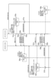
- FIG. 4 is a sequence diagram showing an example of scanning operation of the wireless communication system;
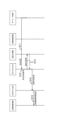
- FIG. 4 is a sequence diagram showing an example of setting change operation of a wireless communication system;
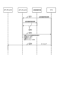
- FIG. 4 is a sequence diagram showing an example of neighbor connection information notification operation of a wireless communication system;
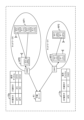
- FIG. 4 is a diagram illustrating an example of sharing neighboring connection information in different networks;
- FIG. 1 is a diagram showing a configuration example of a radio communication system according to an embodiment of the present disclosure.
- the wireless communication system has AP0 to AP3 and STAs.
- AP0 to AP3 may be referred to as AP when they are not distinguished.
- AP0 has a BH (backhaul) line communication unit 1a and an access line communication unit 1b.
- AP1 to AP3 also have a BH line communication section and an access line communication section like AP0.
- the BH line communication unit 1a communicates with AP1 to AP3.
- the BH line communication unit 1a may communicate with AP1 to AP3 using radio or may communicate with AP1 to AP3 using a wire.
- the access line communication unit 1b wirelessly communicates with the STA.
- the access line communication unit 1b communicates with the STA using a channel or frequency band different from that of the BH line communication unit 1a. That is, STAs and APs communicate using access lines, and APs communicate with each other using backhaul lines.
- STA is a mobile communication device. For example, when the STA deteriorates in the communication state with the connected AP due to movement, the STA executes roaming so as to perform wireless communication with an AP having a good communication state.
- STAs may perform roaming based on the IEEE802.11k standard. For example, it is assumed that the STA is connected to AP0 (communicates wirelessly with AP0). The STA requests neighbor connection information from the connected AP0. Upon receiving the neighbor connection information request, AP0 transmits the neighbor connection information to the STA.
- the neighbor connection information transmitted by AP0 includes information for STAs to connect to AP0's neighboring APs.
- the neighbor connection information transmitted by AP0 includes information for STAs to wirelessly communicate with AP0's neighboring APs.
- the neighbor connection information sent by AP0 includes information about the channels that AP0's neighboring APs are using.
- Neighbor connection information may also be referred to as a channel list, roaming information, connection information, or the like.
- the neighbor connection information may be of a small data size so that it may be sent and received using a simple protocol such as message queueing telemetry transport (MQTT).
- MQTT message queueing telemetry transport
- the STA refers to the neighbor connection information received from AP0 and roams from AP0 to AP0's neighbors.
- the neighbor connection information received by the STA from AP0 includes two pieces of channel information, that is, the channel information used by AP1 and the channel information used by AP3.
- the STA scans two channels included in the neighboring connection information and connects to the AP (AP1 or AP3) of the channel with good communication conditions, for example.
- the STA does not need to scan all the channels that can be used for wireless communication with the AP, but only needs to scan the channels included in the neighbor connection information received from AP0, and quickly finds the roaming target. can be found in
- An AP may also be called a base station, a wireless node, or a node.
- a STA may also be referred to as a terminal. Roaming may be referred to as handover.
- Access lines may also be referred to as access channels or access networks.
- a BH line may also be referred to as a BH channel or BH network. BH may be read as relay. Neighborhood may be read as neighborhood or periphery.
- the BH line communication unit 1a and the access line communication unit 1b may be regarded as communication units having a transmission unit and a reception unit. The number of APs and STAs in a wireless communication system is not limited to the example in FIG.
- the AP has a scan operation and a setting change notification operation.
- the AP scans channels on the network to which the AP belongs (eg, channels with the same ESSID as the AP's ESSID (extended service set identifier)) and collects neighbor connection information.
- a request (when) is made to the neighboring AP to notify the AP of the changed content of the setting change. command) is included.
- This request may hereinafter be referred to as a notification registration request.
- the AP In the setting change notification operation, when a setting change such as a channel change is made, the AP notifies neighboring APs of the content of the setting change.
- a change may be read as an update.
- the AP may perform a channel scanning operation at startup, such as after power up or after a reset operation.
- the AP may also periodically perform channel scanning operations. For example, the AP may perform a channel scanning operation in a time zone, such as midnight, when the number of STAs communicating wirelessly is low.
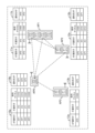
- FIG. 2 is a diagram explaining an example of the scan operation of the AP.
- FIG. 2 shows AP0 to AP3 shown in FIG.
- AP0 has IF0.
- AP1 has IF0-IF3.
- AP2 has IF0 and IF1.
- AP3 has IF0 and IF1.
- IF0 to IF3 may be referred to as IF when not distinguished.
- IF is a wireless interface for wireless communication.
- the IFs may communicate wirelessly in different frequency bands.
- IF0 may perform wireless communication in the 2.4 GHz band.
- IF1 may perform wireless communication in the 5 GHz band.
- the functions of the BH line communication unit and the access line communication unit for wireless communication described in FIG. 1 are realized by the IF.
- the IF performs wireless communication using one of multiple channels.
- IF0 of AP0 shown in FIG. 2 performs wireless communication using CH00 among a plurality of channels.
- IF0 of AP1 shown in FIG. 2 performs wireless communication using CH10 among a plurality of channels.
- a different channel is set for each of the multiple IFs of one AP.
- IF0 of AP1 is set to CH10
- IF1 of AP1 is set to CH11
- IF2 of AP1 is set to CH12
- IF3 of AP1 is set to CH13.
- AP0 stores neighboring connection information 10a and notification destination information 10b.
- AP1 stores neighboring connection information 11a and notification destination information 11b.
- AP2 stores neighboring connection information 12a and notification destination information 12b.
- the AP 3 stores neighboring connection information 13a and notification destination information 13b.
- neighboring connection information 10a to 13a are not distinguished, they may be referred to as neighboring connection information.
- notification destination information 10b to 13b when the notification destination information 10b to 13b are not distinguished, they may be referred to as notification destination information.
- Neighborhood connection information is information for STAs to connect (roam) to neighboring APs.
- Neighboring connection information includes an AP identifier, an IF identifier, and a used channel.
- the AP identifier is an identifier for identifying AP0 to AP3 assigned to AP0 to AP3.
- the IF identifier is an identifier that identifies an IF that the AP has.
- the used channel indicates the channel used by the IF.
- the AP identifier may be a MAC (Media Access Control address) address assigned to the AP.
- the IF identifier may be a MAC address assigned to the IF.
- the notification destination information is information that indicates the notification destination of the content of the setting changes made in the AP.
- the AP1 refers to the notification destination information 11b and notifies the neighboring APs (AP0 and AP2 in the example of the notification destination information 11b in FIG. 2) of the setting change. Notice.
- the AP's neighbor connection information and notification destination information are collected by the AP's scanning operation and stored in the AP's memory.
- AP0 scans channels using an access line and receives beacon signals.
- the beacon signal includes, for example, the AP identifier and IF identifier information of the AP that transmitted the beacon signal.
- AP0 associates the channel on which the beacon signal was received with the AP identifier and IF identifier information included in the beacon signal, and stores neighboring connection information 10a in the memory.
- AP0 receives a beacon signal on channel "CH10". It is assumed that the beacon signal of channel "CH10" includes an AP identifier "AP1" and an IF identifier "IF0".
- AP0 receives a beacon signal on channel "CH12". It is assumed that the beacon signal of channel "CH12" includes an AP identifier "AP1" and an IF identifier "IF2”.
- AP0 receives a beacon signal on channel "CH21". It is assumed that the beacon signal of channel "CH21” includes an AP identifier "AP2" and an IF identifier "IF1".
- AP0 receives a beacon signal on channel "CH30". It is assumed that the beacon signal of channel "CH30" includes an AP identifier "AP3" and an IF identifier "IF0".
- the memory of AP0 stores the neighboring connection information 10a shown in FIG.
- AP0 collects neighboring connection information of APs in the vicinity of AP0 (eg, APs that were able to receive the beacon signal) through channel scanning operation and stores it in memory.
- AP1 to AP3 also scan channels in the same way as AP0 and collect neighboring connection information 11a to 13a.
- AP1-AP3 store the collected neighbor connection information 11a-13a in memory.
- the AP collects neighbor connection information for STAs to connect to neighbor APs in the scanning operation and stores it in memory.
- the vicinity of the AP may be regarded as the vicinity with respect to the distance in radio waves. For example, even if AP0 and AP3 are close to each other in position (arrangement), if radio waves do not reach them (for example, if beacon signals cannot be received due to obstacles, etc.), AP0 and AP3 must not be close to each other. You can catch it.
- the AP requests the neighboring APs to register for notification. That is, when a setting change such as a channel change is performed, the AP requests the neighboring AP to notify the content of the setting change.
- a BH line is used for the notification registration request.
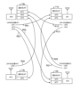
- FIG. 3 is a diagram explaining an example of the operation of a notification registration request.
- the same components as in FIG. 2 are given the same reference numerals.
- AP0 receives the beacon signals of AP1 to AP3, for example, as described in the specific example of FIG. 2 above. Therefore, AP0's neighboring APs are AP1-AP3. In this case, AP0 uses the BH line to transmit notification registration requests R01, R02 and R03 to neighboring AP1 to AP3.
- AP1 to AP3 Upon receiving AP0's notification registration request, AP1 to AP3 store in memory the AP identifier of AP0 that transmitted the notification registration request as notification destination information.
- AP1 that has received the notification registration request R01 of AP0 stores in its memory the AP identifier "AP0" of AP0 that has transmitted the notification registration request, as shown in the notification destination information 11b of FIG.
- AP2 stores in its memory the AP identifier "AP0" of AP0 that transmitted the notification registration request, as shown in the notification destination information 12b of FIG.
- AP3 stores in its memory the AP identifier "AP0" of AP0 that transmitted the notification registration request, as shown in the notification destination information 13b of FIG.
- AP1 to AP3 also transmit notification registration requests to neighboring APs.
- AP1 transmits notification registration requests R10 and R12 to neighboring AP0 and AP2.
- AP0 that has received the notification registration request R10 stores the AP identifier "AP1" of AP1 that has transmitted the notification registration request R10, as shown in the notification destination information 10b of FIG.
- AP2 that has received the notification registration request R12 stores the AP identifier "AP1" of AP1 that has transmitted the notification registration request R12, as shown in the notification destination information 12b of FIG.
- AP2 transmits notification registration requests R20 and R21 to neighboring AP0 and AP1.
- AP0 that has received the notification registration request R20 stores the AP identifier "AP2" of AP2 that has transmitted the notification registration request R20, as shown in the notification destination information 10b in FIG.
- the AP1 that received the notification registration request R21 stores the AP identifier "AP2" of the AP2 that transmitted the notification registration request R21, as shown in the notification destination information 11b of FIG.
- AP3 transmits a notification registration request R30 to neighboring AP0.
- AP0 that has received the notification registration request R30 stores the AP identifier "AP3" of AP3 that has transmitted the notification registration request R30, as shown in the notification destination information 10b of FIG.
- the AP sends notification registration requests to neighboring APs in scanning operations.
- the neighboring AP stores, in its memory, notification destination information indicating the notification destination of the changed content when the setting is changed.
- the AP may, for example, perform the setting change notification operation during normal operation of wirelessly communicating user data with the STA. For example, when a setting change such as a channel change is performed manually or remotely by an operator (for example, an operator terminal connected via a BH line), the AP changes the channel of the access line that wirelessly communicates with the STA. , a setting change notification operation may be performed.
- the AP When a setting change is made, the AP notifies neighboring APs of the changed content of the setting change according to the notification destination AP (AP identifier) of the notification destination information stored in the memory. Neighboring APs change their neighbor connection information based on the notified changes. A BH line is used for notification of the change.
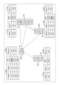
- FIG. 4 is a diagram showing an example of neighboring connection information after channel setting change in AP1.
- the same components as in FIG. 2 are given the same reference numerals.
- AP identifiers "AP0" and "AP2" are stored in the notification destination information 11b of AP1. Therefore, AP1, for example, transfers the AP identifier "AP1" of AP1 whose setting has been changed, information "IF0" of the channel-changed IF, and information "16" of the channel after the channel change to AP0 and AP2. to notify.
- the AP0 that has been notified of the changed content changes the neighboring connection information 10a based on the notified changed content (setting change information). For example, AP0 changes the used channel corresponding to IF0 of AP1 in the neighboring connection information 10a to "CH16", as shown in FIG.
- the AP 2 that has been notified of the changed content changes the neighboring connection information 12a based on the notified changed content. For example, AP2 changes the used channel corresponding to IF0 of AP1 in the neighboring connection information 12a to "CH16", as shown in FIG.
- FIG. 4 an example of changing neighboring connection information in neighboring APs when settings are changed in AP1 has been described, but similar operations are performed in other AP0, AP2, and AP3.
- AP3 it is assumed that the setting has been changed.
- the changed content of AP3 is notified to AP0 (see notification destination information 13b in FIG. 4).
- AP0 changes the connection information at AP3 in the neighbor connection information 10a.
- the neighboring AP transmits the changed contents of the setting change to the AP that made the notification registration request. Therefore, the AP does not have to frequently perform a channel scan using the access line, for example, in order to monitor setting changes such as channel changes at neighboring APs. Also, since the AP does not have to frequently scan channels using the access line, it is possible to reduce opportunities to communicate with STAs.
- the AP can immediately update the neighboring connection information based on the changed content transmitted from the neighboring AP. Therefore, when the AP receives a request for neighbor connection information from the STA, the AP can notify the STA of the latest neighbor connection information. Also, STAs can roam based on up-to-date neighbor attachment information, thus reducing roaming failures to neighbor APs.
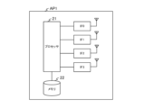
- FIG. 5 is a diagram showing an example of the hardware configuration of AP1. As shown in FIG. 5, AP1 has a processor 21, a memory 22, and IF0 to IF3. Note that the number of IFs is not limited to the example in FIG.
- the processor 21 controls the entire AP1.
- the processor 21 may be, for example, a CPU (central processing unit) or a DSP (digital signal processor).
- the memory 22 stores an OS (operating system) program and application programs to be executed by the processor 21 .
- the memory 22 also stores various data necessary for processing by the processor 21 .
- the memory 22 may be, for example, ROM (Read Only Memory), RAM (Random Access Memory), flash memory, SSD (solid state drive), and/or HDD (hard disk drive).
- IF0 to IF3 are wireless interfaces for wireless communication.
- wireless communication channels are set and changed under the control of the processor 21.
- FIG. IF0 to IF3 wirelessly communicate with STAs via access lines and wirelessly communicate with neighboring APs via BH lines.
- AP1 may communicate with a neighboring AP via a wired BH line.
- AP 1 may have a wired interface connected to processor 21 .
- Processor 21 may communicate with neighboring APs via a wired interface.
- IF0 to IF3 may be referred to as communication units.
- the IF may be referred to as an IF circuit.
- the IF may have circuitry to process access lines and circuitry to process BH lines.
- AP0, AP2, and AP3 also have the same hardware configuration as AP1, and their description is omitted.
- FIG. 6 is a diagram showing an example of the functional configuration of AP1.
- AP1 has a control section 31 .
- the functions of the control unit 31 may be realized by the processor 21 shown in FIG. 5, for example.
- the control unit 31 includes a scan unit 31a, an information generation unit 31b, a request transmission unit 31c, a request reception unit 31d, a change content transmission unit 31e, and a change content reception unit 31f.
- the scanning unit 31a receives beacon signals while changing the channels of IF0 to IF3.
- the scanning unit 31a performs a scanning operation, for example, when AP1 is activated or periodically.
- the information generating unit 31b generates neighboring connection information based on the beacon signal received by the scanning unit 31a.
- the information generator 31b stores the generated neighboring connection information in the memory 22.
- the request transmission unit 31c transmits a notification registration request to neighboring APs of AP1. For example, the request transmitting unit 31c determines that the source AP of the beacon signal received by the scanning unit 31a is a neighboring AP, and transmits the notification registration request to the determined neighboring AP.
- the request receiving unit 31d receives the notification registration request.
- the request receiving unit 31d stores the AP identifier of the neighboring AP that has transmitted the notification registration request in the memory 22 as notification destination information. That is, the request receiving unit 31d stores in the memory 22 notification destination information for transmitting the content of the setting change to the neighboring AP when the setting of the AP1 is changed.
- the change content transmission unit 31e refers to the notification destination information stored in the memory 22 and specifies the neighboring AP to which the change content of the setting change is to be sent.
- the change content transmitting unit 31e transmits the change content to the specified neighboring AP.
- the change content receiving unit 31f receives the change content transmitted from the neighboring AP whose settings have been changed.
- the change content transmission unit 31e changes the neighboring connection information corresponding to the neighboring AP that has transmitted the change content based on the received change content.
- AP0, AP2, and AP3 also have the same functional configuration as AP1, and their description is omitted.
- FIG. 7 is a sequence diagram showing an example of scanning operation of the wireless communication system.
- FIG. 7 illustrates an example of scanning operations in AP0 and AP1.
- AP0 and AP1 may periodically perform the scanning operation shown in FIG. 7, for example, at startup or late at night.
- AP1 performs a channel scan (wireless scan) (S1a).
- S1a channel scan
- AP1 scans channel "CH00" in IF0 of AP0.
- AP1 When AP1 scans the channel "CH00" in IF0 of AP0, it generates neighbor connection information about AP0 and stores it in memory (S2a). For example, AP1 generates and stores neighbor connection information including AP identifier "AP0", IF identifier "IF0", and channel used "CH00" in memory (see, eg, neighbor connection information 11a in FIG. 2).
- AP1 After storing AP0's neighbor connection information in its memory, AP1 confirms that communication is possible with AP0 (S3a). AP1 confirms that communication is possible with AP0 via the BH line. That is, AP1 confirms whether or not it is possible to communicate with AP0, which has been wirelessly scanned, via the BH line. Here, AP1 receives a communicable response from AP0 (S4a). That is, AP1 is connected to AP0 via the BH line.
- AP1 When AP1 receives a communicable response from AP0, it sends a notification registration request to AP0 (S5a). That is, when a setting change such as a channel change is performed in AP0, AP1 requests AP0 to notify AP1 of the content of the setting change.
- AP0 generates notification destination information in response to the notification registration request from AP1 and stores it in memory (S6a). For example, AP0 stores in its memory the contact information having the AP identifier "AP1" of AP1 that has transmitted the notification registration request (see contact information 10b in FIG. 2, for example). As a result, when the setting is changed, AP0 can notify AP1 of the changed content by referring to the notification destination information stored in the memory.
- AP1 when AP1 does not receive the communicable response of S4a, it deletes the neighboring connection information in AP0 (the neighboring connection information of AP0 stored in the memory in S2a) from the memory (S7a). That is, when AP1 is not connected to AP0 via the BH line, it deletes the neighbor connection information in AP0 from its memory. In other words, when AP1 is not connected to AP0 via the BH line, AP1 cannot send a notification registration request to AP0 and cannot receive information about setting changes of AP0. Delete from
- AP0 performs wireless scanning (S1b).
- S1b wireless scanning
- AP0 scans channel "CH10" in IF0 of AP1.
- AP0 When AP0 scans channel "CH10" in IF0 of AP1, it generates neighbor connection information about AP1 and stores it in memory (S2b). For example, AP0 generates and stores neighbor connection information including AP identifier "AP1", IF identifier "IF0", and channel used "CH10" in memory (see, eg, neighbor connection information 10a in FIG. 2).
- AP0 After AP0 stores the neighbor connection information of AP1 in its memory, AP0 confirms that communication is possible with AP1 (S3b). AP0 confirms that communication is possible with AP1 via the BH line. That is, AP0 confirms whether or not it is possible to communicate with AP1, which has been wirelessly scanned, via the BH line. Here, AP0 receives a communicable response from AP1 (S4b). That is, AP0 is connected to AP1 via the BH line.
- AP0 When AP0 receives a communicable response from AP1, it sends a notification registration request to AP1 (S5b). That is, AP0 requests AP1 to notify AP0 of the content of the setting change when setting change such as channel change is performed in AP1.
- AP1 In response to the notification registration request from AP0, AP1 generates notification destination information and stores it in memory (S6b). For example, AP1 stores in its memory the contact information having the AP identifier "AP0" of AP0 that has transmitted the notification registration request (see contact information 11b in FIG. 2, for example). As a result, when the setting is changed, AP1 can notify AP0 of the changed content by referring to the notification destination information stored in the memory.
- AP0 when AP0 does not receive the communicable response of S4b, it deletes the neighboring connection information in AP1 (the neighboring connection information of AP1 stored in the memory in S2b) from the memory (S7b). That is, when AP0 is not connected to AP1 via the BH line, AP0 deletes the neighbor connection information in AP1 from its memory. In other words, when AP0 is not connected to AP1 via the BH line, AP0 cannot send a notification registration request to AP1 and cannot receive information about changes in the settings of AP1. Delete from
- AP0 and AP1 can transmit the neighboring connection information to the STA when receiving the neighboring connection information transmission request from the STA. Also, when the settings are changed, AP0 and AP1 can notify the neighboring APs of the contents of the setting change by referring to the notification destination information stored in the memory.
- AP0 and AP1 autonomously generate neighbor connection information and store it in memory.
- AP0 and AP1 can prevent, for example, manual input errors in neighboring connection information.
- AP0 and AP1 can save the trouble of manually inputting neighboring connection information.
- AP0 and AP1 can reduce the network load due to scanning by adjusting the time period during which scanning is performed.
- FIG. 8 is a sequence diagram showing an example of setting change operation of the wireless communication system.
- FIG. 8 illustrates an example of a setting change operation in AP0 and AP1.
- FIG. 8 shows an operator terminal connected to the BH line.
- AP0 and AP1 may execute the setting change operation shown in FIG. 8, for example, when the setting is changed by the operator during normal operation of wirelessly communicating user data with the STA.
- the operator terminal changes the settings for AP1 (S11).
- AP1 changes the settings of AP1 according to the change of settings of the operator terminal (S12).
- AP1 After making the setting change, AP1 refers to the notification destination information stored in the memory and identifies the AP that will notify (transmit) the content of the setting change (S13). Here, AP1 identifies AP0.
- AP1 uses the BH line to transmit the changed content of the setting change to the specified AP0 (S14).
- AP0 changes AP1's neighbor connection information stored in its memory based on the change sent from AP1 (S15).
- AP0 does not have to frequently perform channel scanning using the access line, for example, in order to monitor setting changes such as channel changes being made in neighboring AP1.
- AP0 does not have to frequently scan channels using access lines, it is possible to reduce opportunities to communicate with STAs.
- AP1 uses the BH line to transmit the changed content of the setting change to AP0. As a result, it is possible to suppress a decrease in the communication speed of the access line.
- AP0 can immediately update the neighboring connection information based on the content of the change transmitted from neighboring AP1 when the settings are changed in neighboring AP1. Therefore, when AP0 receives a request for neighbor connection information from a STA, AP0 can notify the STA of the latest neighbor connection information.
- AP0 autonomously changes neighbor connection information. As a result, AP0 can prevent, for example, manual input errors in the content of changes. In addition, AP0 can save the trouble of manually inputting the contents of changes.
- FIG. 9 is a sequence diagram showing an example of neighbor connection information notification operation of the wireless communication system.
- FIG. 9 illustrates an example of neighbor connection information operation in AP1, AP0, and STAs.
- the STA requests neighbor connection information from AP1 (S21). For example, when the signal reception quality at AP1 falls below a threshold, the STA requests AP1 for neighbor connection information.
- the signal reception quality may be, for example, RSSI (received signal strength indicator), SINR (signal-to-interference plus noise power ratio), or SNR (signal-noise ratio).
- AP1 acquires the neighboring connection information stored in the memory in response to the request for neighboring connection information from the STA (S22). That is, AP1 acquires from memory information for the STA to connect to AP1's neighbor AP (AP0).
- AP1 transmits the obtained neighbor connection information to the STA (S23).
- the STA roams to AP1's neighboring AP (here, AP0) based on the received neighboring connection information (S24).
- the neighboring connection information may include neighboring connection information of a plurality of neighboring APs.
- a STA may roam to a given neighboring AP according to a given algorithm if the received neighboring attachment information includes the connection information of multiple neighboring APs.
- the STA can roam from the currently connected AP1 to the neighboring AP0.
- AP1 immediately stores the latest neighboring connection information after the setting change in memory even if the setting is changed in neighboring AP0. Therefore, the STA can roam based on the latest neighbor connection information, thereby reducing roaming failures to neighboring APs that have undergone configuration changes.
- APs transmit neighbor connection information for connecting STAs to neighboring APs in response to requests from STAs.
- An AP's IF receives (scans) signals such as beacon signals of neighboring APs.
- the controller 31 of the AP generates neighbor connection information based on the signal received by the IF.
- the IF of the AP receives the setting change information (contents of the change) regarding the change of the wireless communication setting performed in the neighboring AP from the neighboring AP, and the controller 31 of the AP receives the setting change information from the neighboring AP. change the neighbor connection information based on
- the AP generates neighboring connection information based on signals from neighboring APs, and changes the generated neighboring connection information based on configuration change information transmitted from neighboring APs. This allows the AP to maintain pertinent neighbor attachment information. For example, assume that a neighboring AP has changed channels. In this case, the AP receives channel information after the channel change from neighboring APs. This allows the AP to change the channel information of the generated neighbor connection information and retain the appropriate neighbor connection information.
- An AP may determine neighbor attachment information to send to STAs based on the reception quality of signals at neighboring APs.
- the AP stores the reception quality of beacon signals received from neighboring APs along with neighboring connection information stored in memory.
- the AP sends neighbor connection information corresponding to reception quality above the threshold to the STAs. That is, the neighbor connection information includes the signal reception quality of neighboring APs, and the APs send the neighbor connection information corresponding to the reception quality exceeding the threshold to the STAs. This allows the STA to roam to neighboring APs with good signal quality.
- the AP may store in its memory neighbor connection information with reception quality exceeding the threshold.
- the AP may send neighbor connection information with reception quality above a threshold stored in memory to the STAs. This also allows the STA to roam to neighboring APs with good signal quality.
- the AP may be configured with a maximum number of neighbor attachment information to send to the STAs. For example, the AP may send up to 6 neighbor attachment information to the STAs.
- the maximum number of neighbor attachment information to send to STAs may be different for each AP.
- the maximum number of neighbor connection information may differ based on the geographical distance to neighboring APs. For example, when the distance to the neighboring AP is long, the maximum number of neighboring connection information to be sent to the STA may be decreased or increased.
- the STA takes time to determine the roaming target.
- the STA's roaming target determination process is limited by determining the maximum number of neighbor attachment information that can be sent from the AP to the STA. This allows the STA to reduce the roaming target determination processing time.
- the AP may determine the neighboring connection information of neighboring APs to be collected based on the connection order of the neighboring APs on the BH line. For example, an AP may collect neighbor connection information for neighboring APs at connection orders below a threshold.
- the positional distance between an AP and neighboring APs is assumed to be smaller as the connection order in the BH line is smaller. It is assumed that the smaller the distance between the AP and the neighboring AP, the less the deterioration of the signal quality when the STA roams from the AP to the neighboring AP. In other words, it is assumed that the AP collects neighboring connection information of neighboring APs at connection degrees equal to or lower than the threshold, thereby suppressing deterioration in communication quality when STAs roam from APs to neighboring APs. This allows the STA to perform roaming while suppressing deterioration in communication quality.
- the AP scan operation and/or the configuration change notification operation may be performed by dedicated hardware. This allows the AP to speed up the scanning operation.
- APs may share neighbor attachment information for different networks.
- an AP may share neighbor connection information of neighboring APs belonging to networks with different network names.
- FIG. 10 is a diagram explaining an example of sharing neighboring connection information in different networks.
- the same components as in FIG. 2 are given the same reference numerals.
- FIG. 10 shows neighboring connection information 10a stored in the memory of AP0 and neighboring connection information 13a stored in the memory of AP3.
- AP0 and AP1 belong to the network with network name "0".
- AP3 and AP4 belong to a network with network name "0”.
- AP0 is connected to GW (gateway)0.
- AP3 is connected to GW1.
- GW0 and GW1 are connected via a relay server 41 .
- AP1 and AP3 are considered to be near each other in terms of radio waves. That is, AP3 is assumed to be a neighboring AP of AP1.
- AP0 which has the neighboring connection information 10a of AP1 may transmit the neighboring connection information 10a regarding AP1 to AP3 belonging to another network (AP3 is a neighboring AP of AP1) via the relay server 41. Then, when AP3 receives a notification request of neighboring connection information from an STA, AP3 may transmit to the STA the neighboring connection information 13a belonging to the same network and the neighboring connection information 10a of AP1 belonging to another network. This allows STAs to roam between different networks.
- AP0 and AP2 are considered to be radio-related neighbors. That is, AP2 is assumed to be a neighboring AP of AP0.
- AP3 which has the neighboring connection information 13a of AP2, may transmit the neighboring connection information 13a regarding AP2 to AP0 belonging to another network (AP0 is a neighboring AP of AP2) via the relay server 41. Then, when AP0 receives a notification request of neighboring connection information from an STA, AP0 may transmit to the STA the neighboring connection information 10a belonging to the same network and the neighboring connection information 13a of AP2 belonging to another network. This allows STAs to roam between different networks.
- the present disclosure is useful for wireless communication systems such as wireless LANs (local area networks).
- BH line communication unit 1b access line communication unit 10a to 13a neighboring connection information 10b to 13b notification destination information 21 processor 22 memory 31 control unit 31a scan unit 31b information generation unit 31c request transmission Part 31d Request reception part 31e Change content transmission part 31f Change content reception part 41 Relay server
Landscapes
- Engineering & Computer Science (AREA)
- Computer Networks & Wireless Communication (AREA)
- Signal Processing (AREA)
- Databases & Information Systems (AREA)
- Computer Security & Cryptography (AREA)
- Mobile Radio Communication Systems (AREA)
Priority Applications (3)
| Application Number | Priority Date | Filing Date | Title |
|---|---|---|---|
| CN202280074303.0A CN118216186A (zh) | 2021-11-10 | 2022-09-20 | 无线节点及无线通信方法 |
| US18/708,347 US20250344053A1 (en) | 2021-11-10 | 2022-09-20 | Wireless node and wireless communication method |
| JP2023559458A JPWO2023084920A1 (cg-RX-API-DMAC7.html) | 2021-11-10 | 2022-09-20 |
Applications Claiming Priority (2)
| Application Number | Priority Date | Filing Date | Title |
|---|---|---|---|
| JP2021-183346 | 2021-11-10 | ||
| JP2021183346 | 2021-11-10 |
Publications (1)
| Publication Number | Publication Date |
|---|---|
| WO2023084920A1 true WO2023084920A1 (ja) | 2023-05-19 |
Family
ID=86335555
Family Applications (1)
| Application Number | Title | Priority Date | Filing Date |
|---|---|---|---|
| PCT/JP2022/034984 Ceased WO2023084920A1 (ja) | 2021-11-10 | 2022-09-20 | 無線ノード及び無線通信方法 |
Country Status (4)
| Country | Link |
|---|---|
| US (1) | US20250344053A1 (cg-RX-API-DMAC7.html) |
| JP (1) | JPWO2023084920A1 (cg-RX-API-DMAC7.html) |
| CN (1) | CN118216186A (cg-RX-API-DMAC7.html) |
| WO (1) | WO2023084920A1 (cg-RX-API-DMAC7.html) |
Citations (2)
| Publication number | Priority date | Publication date | Assignee | Title |
|---|---|---|---|---|
| JP2008535311A (ja) * | 2005-03-29 | 2008-08-28 | エルジー エレクトロニクス インコーポレイティド | マルチメディアブロードキャスト/マルチキャストサービスセル再設定 |
| JP2011139500A (ja) * | 2011-02-14 | 2011-07-14 | Qualcomm Inc | 分散制御によるオーバーヘッドメッセージの更新 |
-
2022
- 2022-09-20 JP JP2023559458A patent/JPWO2023084920A1/ja active Pending
- 2022-09-20 CN CN202280074303.0A patent/CN118216186A/zh active Pending
- 2022-09-20 US US18/708,347 patent/US20250344053A1/en active Pending
- 2022-09-20 WO PCT/JP2022/034984 patent/WO2023084920A1/ja not_active Ceased
Patent Citations (2)
| Publication number | Priority date | Publication date | Assignee | Title |
|---|---|---|---|---|
| JP2008535311A (ja) * | 2005-03-29 | 2008-08-28 | エルジー エレクトロニクス インコーポレイティド | マルチメディアブロードキャスト/マルチキャストサービスセル再設定 |
| JP2011139500A (ja) * | 2011-02-14 | 2011-07-14 | Qualcomm Inc | 分散制御によるオーバーヘッドメッセージの更新 |
Also Published As
| Publication number | Publication date |
|---|---|
| CN118216186A (zh) | 2024-06-18 |
| JPWO2023084920A1 (cg-RX-API-DMAC7.html) | 2023-05-19 |
| US20250344053A1 (en) | 2025-11-06 |
Similar Documents
| Publication | Publication Date | Title |
|---|---|---|
| JP6710307B2 (ja) | モバイル通信ネットワークにおけるハンドオーバを制御する方法並びに当該方法を実装した装置及びシステム | |
| US7403506B2 (en) | Seamless handoff method in wireless local area network | |
| US8437753B2 (en) | Method for managing neighbor base station information in mobile communication system and system thereof | |
| JP5260251B2 (ja) | コグニティブ無線システムにおける利用周波数帯調整方法および無線通信装置 | |
| US9137727B2 (en) | Controlled client roaming | |
| US20080130597A1 (en) | Apparatus, system and method for managing wireless local area network service based on a location of a multi-mode portable communication device | |
| US20070021119A1 (en) | Apparatus and method for implementing handoff between heterogeneous networks in a wireless communication system | |
| US20100329206A1 (en) | Dual idle-traffic state of wireless communication device | |
| EP3679744B1 (en) | Method in a cellular telecommunications network, computer program, computer-readable data carrier and network node. | |
| JP6467543B2 (ja) | 通信システム、ユーザ端末、プロセッサ及び通信制御方法 | |
| JP7681968B2 (ja) | Iabノード、iabノードの制御方法、およびプログラム | |
| US20100234039A1 (en) | Communication system with femtocells and an interference control method therefor | |
| CN105075309A (zh) | 一种基于小区覆盖区指示调整小区覆盖区的方法 | |
| US9973951B1 (en) | Use of UE-capability reporting to control UE service | |
| WO2011129231A1 (ja) | 無線通信システム、無線基地局、及び通信パラメータ再設定方法 | |
| TW202437786A (zh) | 用於無線連接的動態路徑選擇技術 | |
| US20110222522A1 (en) | Radio Station System for a Wireless Network | |
| JP7634979B2 (ja) | 通信装置、通信装置の制御方法、およびプログラム | |
| CN117676737A (zh) | 一种网络切换方法及相关设备 | |
| US20250344053A1 (en) | Wireless node and wireless communication method | |
| JP6112837B2 (ja) | 移動通信システム、移動通信装置、固定中継装置及び集線装置 | |
| JP6112838B2 (ja) | 移動通信システム、移動通信装置、固定中継装置及び集線装置 | |
| JP6361013B2 (ja) | 無線基地局装置、無線通信システム、及び、無線基地局装置の制御方法 | |
| KR101658237B1 (ko) | 모바일 통신 네트워크에서 모바일 라우터의 이동성 관리 방법 및 그 장치 | |
| WO2009106791A1 (en) | Mobile communication access point |
Legal Events
| Date | Code | Title | Description |
|---|---|---|---|
| 121 | Ep: the epo has been informed by wipo that ep was designated in this application |
Ref document number: 22892421 Country of ref document: EP Kind code of ref document: A1 |
|
| ENP | Entry into the national phase |
Ref document number: 2023559458 Country of ref document: JP Kind code of ref document: A |
|
| WWE | Wipo information: entry into national phase |
Ref document number: 202280074303.0 Country of ref document: CN |
|
| 122 | Ep: pct application non-entry in european phase |
Ref document number: 22892421 Country of ref document: EP Kind code of ref document: A1 |
|
| WWP | Wipo information: published in national office |
Ref document number: 18708347 Country of ref document: US |