WO2023084763A1 - 光通信経路開通方法及び管理制御装置 - Google Patents
光通信経路開通方法及び管理制御装置 Download PDFInfo
- Publication number
- WO2023084763A1 WO2023084763A1 PCT/JP2021/041838 JP2021041838W WO2023084763A1 WO 2023084763 A1 WO2023084763 A1 WO 2023084763A1 JP 2021041838 W JP2021041838 W JP 2021041838W WO 2023084763 A1 WO2023084763 A1 WO 2023084763A1
- Authority
- WO
- WIPO (PCT)
- Prior art keywords
- optical
- port
- management control
- transmission
- subscriber
- Prior art date
- Legal status (The legal status is an assumption and is not a legal conclusion. Google has not performed a legal analysis and makes no representation as to the accuracy of the status listed.)
- Ceased
Links
Images





Classifications
-
- H—ELECTRICITY
- H04—ELECTRIC COMMUNICATION TECHNIQUE
- H04L—TRANSMISSION OF DIGITAL INFORMATION, e.g. TELEGRAPHIC COMMUNICATION
- H04L49/00—Packet switching elements
- H04L49/10—Packet switching elements characterised by the switching fabric construction
- H04L49/112—Switch control, e.g. arbitration
Definitions
- the present invention relates to an optical communication path opening method and a management control device.
- a subscriber device needs to open an optical path to connect with a subscriber device to communicate with.
- 12 and 13 are diagrams for explaining a method of opening an optical path in the conventional optical communication system 100.
- a conventional optical communication system 100 includes a plurality of subscriber units 200-1 to 200-3, a plurality of subscriber units 300-1 to 300-3, and a plurality of control units 400-1. 400-2 and a plurality of optical SWs 500-1 to 500-2.
- the subscriber unit 200-1 is not connected to the optical SW 500-1, and the subscriber units 200-2 to 200-3 are connected to the optical SW 500-1 via optical transmission lines. 300-1 to 300-3 are assumed to be connected to the optical SW 500-2 via optical transmission lines.
- the optical SW 500-1 and the optical SW 500-2 are connected via an optical communication NW 600 composed of an optical transmission line.
- Control unit 400-1 manages subscriber unit 200 and controls the operation of optical SW 500-1.
- Control unit 400-2 manages subscriber unit 300 and controls the operation of optical SW 500-2.
- optical SW control unit 410 sets the connection between the ports of optical SW 500-1 so that subscriber unit 200-1 communicates with subscriber unit management control unit 420. .
- information required for registration and authentication of the subscriber device 200-1 is exchanged between the subscriber device 200-1 and the subscriber device management control unit 420, and the subscriber device management control unit 420
- the user device 200-1 can be instructed on the emission wavelength to be used for transmission/reception.
- a control signal called AMCC can be used as a signal for management and control of subscriber units.
- the AMCC signal includes status information indicating, for example, the transmission/reception wavelength of the optical transmitter/receiver, transmission light intensity, temperature, and the like.
- the optical SW control unit 410 controls the subscriber device 300 (for example, subscriber The port-to-port connection setting of the optical SW 500-1 is changed so that the data is transferred to the remote device 300-1).
- control unit 400-2 controls optical SW 500 so that an optical signal transmitted from subscriber device 200-1 is transferred to subscriber device 300 (for example, subscriber device 300-1) serving as a communication partner. Change the port-to-port connection setting of -2. As a result, as shown in FIG. 13, the optical path connecting the subscriber device 200-1 and the subscriber device 300-1 can be opened.
- each subscriber unit 200 and optical SW 500-1 are connected by one optical transmission line, and upstream optical signals from each subscriber unit 200 to optical SW 500-1 are transmitted.
- This is a one-core bidirectional transmission configuration in which downstream optical signals from the optical SW 500-1 to the subscriber unit 200 are wavelength-multiplexed in one optical transmission line.
- the subscriber unit and the optical switch are connected by two optical transmission lines, and the upstream optical signal and the downstream optical signal are transmitted by different optical transmission lines.
- a two-core transmission network configuration may be adopted.
- a coherent transceiver obtains high reception sensitivity by interfering local light with high optical intensity with an input optical signal to extract a beat component as a signal component.
- the local light source becomes unnecessary and the cost of the optical transceiver can be improved.
- FIG. 14 is a diagram showing the configuration of an optical communication system 100a that performs two-core transmission.
- an optical communication system 100a includes a subscriber unit 200a, a subscriber unit 300, a plurality of control units 400-1 to 400-2, and a plurality of optical SWs 500-1 to 500-2.
- subscriber unit 200a is not connected to optical SW 500-1
- subscriber unit 300 is connected to optical SW 500-2 via an optical transmission line.
- control unit 400-1 causes optical SW 500-1 to transfer the optical signal transmitted from subscriber device 200a to subscriber device 300a, which is the communication partner, and transmit the optical signal from subscriber device 300a, which is the communication partner.
- Two optical SWs eg, optical SW 500-1) connected to the subscriber device (eg, subscriber device 200a) via an optical transmission line so as to transfer the received optical signal to the subscriber device 200a. Ports must be recognized as pairs.
- Control unit 400-2 causes optical SW 500-2 to transfer an optical signal transmitted from subscriber unit 200a to subscriber unit 300a as a communication partner, and to transfer the optical signal transmitted from subscriber unit 300a as a communication partner.
- Two ports of an optical SW eg, optical SW 500-2 connected to a subscriber device (eg, subscriber device 300a) via an optical transmission line are paired so as to transfer a signal to the subscriber device 200a.
- first port 510-1 and first port 510-2 of optical SW 500-1 are two ports connected to subscriber unit 200a via an optical transmission line.
- Second port 520-1 and second port 520-3 of SW 500-2 are two ports connected to subscriber unit 300a via an optical transmission line.
- an optical cable is used to bundle multiple optical transmission lines from a carrier building to the area. are installed, and an optical transmission line used for accommodating the subscriber equipment in the subscriber's premises is drawn from, for example, a telephone pole near the subscriber's premises.
- the present invention provides an optical communication system that performs two-core transmission, and is capable of opening an optical path for communicatively connecting a newly connected subscriber unit and a subscriber unit serving as a communication partner.
- the purpose is to provide the technology that can
- At least one subscriber unit to be newly connected and one or more optical switches are connected by a plurality of optical transmission lines, and an upstream optical signal and a downstream optical signal are connected.
- a method for opening an optical communication path in an optical communication system that performs two-core transmission in which different optical transmission paths are used for transmission, wherein the one or more optical switches have a plurality of first ports and a plurality of second ports , the management control device controls the other first port grouped with the transmission port connection first port of the one or more optical switches connected to the transmission port of the one subscriber unit when the response request signal is received.
- connection is switched so as to sequentially connect to one input second port, and the management control device transmits a response request signal via the one second port each time the connection is switched, and the management control device
- the device identifies a reception port connection first port connected to the reception port of the one subscriber device in response to receiving a response signal to the response request signal, and the management control device specifies the transmission port.
- the optical signal input to the connection first port reaches the optical transmission line to which the reception port of another subscriber unit as a communication partner is connected, and is transmitted from the transmission port of the other subscriber unit.
- An optical communication path opening method for setting a connection relationship between ports of the one or more optical switches so that an optical signal reaches the reception port connection first port.
- At least one subscriber unit to be newly connected and one or more optical switches are connected by a plurality of optical transmission lines, and an upstream optical signal and a downstream optical signal are connected.
- a management control device provided in an optical communication system that performs two-core transmission in which different optical transmission paths are used, wherein the one or more optical switches have a plurality of first ports and a plurality of second ports , the other first port grouped with the transmission port connection first port of the one or more optical switches connected to the transmission port of the one subscriber unit is set to one to which a response request signal is input.
- An optical switch control unit that switches connections so as to sequentially connect to the second port, and a subscriber unit management control unit that transmits a response request signal via the one second port each time the connection is switched.
- the subscriber unit management control unit in response to receiving a response signal to the response request signal, specifies a reception port connection first port connected to the reception port of the one subscriber unit;
- the switch control unit causes the optical signal input to the transmission port connection first port to reach the optical transmission line to which the reception port of another subscriber unit with which the communication partner is connected, and to the other subscriber.
- a management control device for setting a connection relationship between ports of the one or more optical switches so that an optical signal transmitted from a transmission port of the device reaches the reception port connection first port.
- an optical communication system that performs two-core transmission, it is possible to open an optical path that communicatively connects a newly connected subscriber device and a subscriber device that is a communication partner.
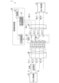
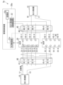
- FIG. 1 is a diagram illustrating a configuration example of an optical communication system according to a first embodiment
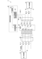
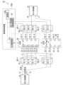
- FIG. FIG. 4 is a diagram for explaining a pairing process of optical SW ports in the first embodiment
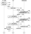
- 4 is a sequence diagram showing the flow of processing in the optical communication system according to the first embodiment
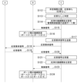
- FIG. 4 is a sequence diagram showing the flow of processing in the optical communication system according to the first embodiment
- FIG. FIG. 2 is a diagram showing a state in which subscriber devices are connected so as to be communicable in the first embodiment
- FIG. 10 is a diagram illustrating a configuration example of an optical communication system according to a second embodiment
- FIG. 10 is a diagram for explaining pairing processing of each port of each optical SW in the second embodiment
- FIG. 11 is a sequence diagram showing the flow of processing in an optical communication system according to the second embodiment;
- FIG. 11 is a sequence diagram showing the flow of processing in an optical communication system according to the second embodiment;
- FIG. 11 is a diagram illustrating a configuration example of an optical communication system according to a third embodiment;
- FIG. 12 is a diagram for explaining pairing processing of each port of each optical SW in the third embodiment;
- FIG. 2 is a diagram for explaining a method of opening an optical path in a conventional optical communication system;
- FIG. 2 is a diagram for explaining a method of opening an optical path in a conventional optical communication system;
- 1 is a diagram showing the configuration of an optical communication system that performs two-core transmission;
- FIG. 1 is a diagram showing a configuration example of an optical communication system 1 according to the first embodiment.
- the optical communication system 1 includes one or more subscriber units 10, one or more subscriber units 15, a management control unit 20, and one or more optical SW30.
- the optical communication system 1 in communication between the subscriber unit 10 and the subscriber unit 15, two-core transmission using different optical transmission lines for transmission and reception is performed.
- the optical transmission line is, for example, an optical fiber.
- FIG. 1 shows a configuration in which the optical communication system 1 includes one subscriber unit 10, one subscriber unit 15 and one optical SW 30, but a plurality of subscriber units 10, 15 and optical SW 30 are provided. may be provided. For example, a new optical SW may be provided between the subscriber unit 15 and the optical SW 30 as in FIG.
- An optical cable 40 is provided between the subscriber device 10 and the optical SW 30, and an optical cable 45 is provided between the subscriber device 15 and the optical SW 30.
- the optical cable 40 accommodates multiple optical transmission lines 41
- the optical cable 45 accommodates multiple optical transmission lines 46 .
- the subscriber unit 10 communicates using two optical transmission lines 41-1 and 41-2. 3 and 46-4 for communication using two optical transmission lines.
- FIG. 1 shows, as an example, a configuration in which the management control device 20 is connected to the optical SW 30 via two optical transmission lines 46-1 and 46-2.
- the subscriber device 10 is equipped with an optical transceiver.
- Optical transceivers are, for example, coherent transceivers.
- the subscriber unit 10 transmits an optical signal via the transmission port 11 and the optical transmission line 41-1 and receives an optical signal via the optical transmission line 41-2 and the reception port 12 by the optical transceiver.
- the subscriber unit 10 is a subscriber unit newly connected to the optical SW 30 .
- the subscriber device 15 is a device that communicates with the subscriber device 10 .
- Subscriber unit 15 comprises an optical transceiver.
- Subscriber unit 15 receives optical signals via receive port 16 and transmits optical signals via transmit port 17 by means of an optical transceiver.
- the optical SW 30 has M (M is an integer of 2 or more) ports 31 , N (N is an integer of 2 or more) ports 32 , and M photodetectors 33 .
- M is an integer of 2 or more
- N is an integer of 2 or more
- M photodetectors 33 M photodetectors
- the number of M and N is assumed to be four.
- An optical signal input to one port of the optical SW 30 is output from another port.
- an optical signal input to port 31 of optical SW 30 is output from port 32 .
- the port 31 is one aspect of the first port
- the port 32 is one aspect of the second port.
- An optical transmission line 41 is connected to each port 31 of the optical SW 30 .
- the port 31-1 of the optical SW 30 is connected to the optical transmission line 41-1
- the port 31-2 of the optical SW 30 is connected to the optical transmission line 41-2.
- An optical transmission line 46 is connected to each port 32 of the optical SW 30 .
- the port 32-1 of the optical SW 30 is connected to the optical transmission line 46-1, and the port 32-2 of the optical SW 30 is connected to the optical transmission line 42-2.
- the photodetector 33-m (1 ⁇ m ⁇ M) is provided in association with the port 31-m.
- the photodetector 33-m detects an optical signal input to the port 31-m.
- the light detection unit 33-m detects an optical signal
- the light detection unit 33-m notifies the management control device 20 of the detection of the optical signal.
- the notification from the light detection unit 33 - m to the management control device 20 may be performed via an electric line connecting the management control device 20 and the optical SW 30 .
- the photodetector 33 is applied only to the port 31-m to which the transmission port 11 of the subscriber device 10 is connected. -m are provided, but other subscriber devices (eg, subscriber device 15) are connected to ports 32-n (1 ⁇ n ⁇ N).
- the port 32-n which is the port to which the transmission port of the user equipment is connected, may also be provided with the photodetector 33-n.
- the management control device 20 controls at least the subscriber devices 10 and 15 and the optical SW 30 .
- the control of the subscriber units 10 and 15 includes, for example, allocation of light emission wavelengths to the subscriber units 10 and 15, instructions to stop light, instructions to change wavelengths, and the like.
- the control of the optical SW 30 is, for example, connection switching between ports of the optical SW 30 .
- the management control device 20 includes an optical SW control section 21 , a subscriber device management control section 22 and a storage section 23 .
- the optical SW control unit 21 sets and switches connections between ports of the optical SW 30 .
- the subscriber device management control unit 22 identifies to which port of the optical SW 30 the subscriber device newly connected to the optical SW 30 is connected. Then, optical path opening processing such as wavelength allocation is performed.
- the management control device 20 has a transmission port and a reception port for exchanging optical signals via the optical SW 30 .
- the reception port of the management control device 20 is connected to the optical SW 30 via the optical transmission line 46-1
- the transmission port of the management control device 20 is connected to the optical SW 30 via the optical transmission line 46-2.
- the functions of the optical SW control unit 21 and the subscriber unit management control unit 22 may be realized by one or more processors executing programs.
- the storage unit 23 stores subscriber information, grouping information, and light detection unit installation information.
- Subscriber information is information about subscriber devices 10 and 15 .
- the subscriber information includes, for example, information indicating to which port of the optical SW 30 each of the transmission ports and reception ports of the subscriber devices 10 and 15 is connected, and information on wavelengths assigned to the subscriber devices 10 and 15. include.
- Grouping information is information for identifying ports belonging to the same group.
- the grouping information includes, for example, identification information of ports belonging to the same group for each group.
- the grouping information includes the ports 31 (for example, ports 31-1 to 31-4) of the optical SW 30 to which the optical transmission lines 41 accommodated in the optical cables 40 are connected as one group.
- ports 32 for example, ports 32-1 to 32-4) of the optical SW 30 to which the optical transmission line 46 housed in the optical cable 45 is connected are defined as one group.
- the photodetector installation information represents information on the port 31 in which the photodetector 33-m is installed.
- a plurality of optical transmission lines are accommodated from the telecommunications carrier building to that area.
- a plurality of optical transmission lines accommodated in one optical cable correspond to grouped optical transmission lines.
- a plurality of optical transmission lines accommodated in one optical cable are each connected to the port 31 or port 32 of the optical SW 30 . Therefore, the administrator of the optical communication system groups the ports 31 or 32 of the optical SW 30 to which the grouped optical transmission lines are connected among the plurality of optical transmission lines accommodated in one optical cable into one group.
- the information may be stored in the storage unit 23 as grouping information.
- FIG. FIG. 2 is a diagram for explaining port pairing processing of the optical SW 30 in the first embodiment.
- the transmission port 11 of the subscriber unit 10 is connected to the port 31-1 of the optical SW 30 through the optical transmission line 41-1, and the reception port 12 of the subscriber unit 10 is connected through the optical transmission line 41-2. Assume that it is connected to the port 31-2 of the optical SW30.
- the subscriber unit 10 transmits an optical signal to the optical SW30.
- the optical detector 33-1 of the optical SW 30 can detect the input of a new optical signal to the optical SW 30 when the optical signal transmitted from the subscriber unit 10 is input to the optical SW 30.
- FIG. The optical signal may not contain data at this stage.
- the management control device 20 detects the input of the optical signal to the port 31 associated with the light detection unit 33-1.
- -1 is connected to the transmit port 11 of the newly connected subscriber unit 10 .
- the management control device 20 connects the optical switch 30 so that the port 31-1 associated with the light detection unit 33-1 that has detected the input of the optical signal is connected to the reception port of the subscriber device management control unit 22. Set the connection relationship between port 31 and port 32 .
- the management control device 20 manages the optical signal transmitted from the subscriber unit 10 by setting the ports 31-1 and 32-1 of the optical SW 30 to be connected. It can be transmitted to the control device 20 .
- the processing up to this point is related to the transmission port 11 of the subscriber unit 10 .
- the management control device 20 refers to the grouping information stored in the storage unit 23, and grouped with the port 31-1 associated with the light detection unit 33-1 that has detected the input of the optical signal. Identifies the other port 31 that is The optical SW control unit 21 of the management control device 20 switches the connection relationship between the ports 31 and 32 of the optical SW 30 so that the specified other ports are sequentially connected to the transmission ports of the management control device 20 .
- the other ports 31 grouped with port 31-1 are ports 31-2 to 31-4.
- the subscriber device management control section 22 sends out a response request signal via the transmission port and the optical transmission line 46-2. do.
- the response request signal is a signal for requesting transmission of a response from the subscriber unit 10 that has received the signal.
- the subscriber unit 10 transmits a response signal from the transmission port 11 when receiving the response request signal transmitted from the management control unit 20 .
- the management control device 20 When the management control device 20 receives a response signal within the receivable period of the response signal to the response request signal transmitted to the subscriber device 10 via another port 31-m, the subscriber who transmitted the response signal It can be recognized that the receiving port 12 of the device 10 is connected to another port 31-m. For example, when the management control device 20 receives a response signal within the receivable period of the response signal to the response request signal transmitted to the subscriber device 10 via the port 31-2, the subscriber who transmitted the response signal It can be recognized that the receiving port 12 of the device 10 is connected to the port 31-2.
- the management control device 20 can recognize the port 31 of the optical SW 30 to which the transmission port 11 and reception port 12 of the newly connected subscriber device 10 are connected.
- the management control device 20 retains information regarding the recognized combination of the ports 31 of the two optical SWs 30 .
- the method of pairing two ports of the optical SW 30 connected by two optical transmission lines between the management control device 20 and a newly connected subscriber device has been described above. End explanation.
- FIGS. 3 and 4 are sequence diagrams showing the flow of processing in the optical communication system 1 according to the first embodiment. It is assumed that the subscriber unit 10 is not connected to the optical SW 30 when the processing of FIGS. 3 and 4 is started. Assume that the user connects the transmission port 11 of the subscriber unit 10 to the optical transmission line 41-1, and connects the reception port 12 of the subscriber unit 10 to the optical transmission line 41-2. As a result, the subscriber unit 10 is connected to the optical SW 30 via the optical transmission line 41 (step S101). The subscriber unit 10 transmits an optical signal from the transmission port 11 to the optical transmission line 41-1 (step S102). An optical signal transmitted from the subscriber unit 10 is input to the port 31-1 of the optical SW 30 via the optical transmission line 41-1.
- the photodetector 33-1 of the optical SW 30 detects the optical signal input to the port 31-1 (step S103).
- the photodetector 33-1 transmits a detection result indicating that the optical signal has been detected to the management control device 20 (step S104).
- the optical SW control unit 21 of the management control device 20 acquires the detection result transmitted from the light detection unit 33-1.
- the optical SW control unit 21 refers to the light detection unit installation information stored in the storage unit 23, and the port 31 (for example, port 31-1) in which the light detection unit 33-1 that has notified the detection result is installed. identify. Thereby, the optical SW controller 21 recognizes that the transmission port 11 of the subscriber unit 10 is connected to the port 31-1 of the optical SW 30.
- the optical SW control unit 21 sets the connection relationship between the ports of the optical SW 30 (step S105). Specifically, the optical SW control unit 21 connects the port 31-1 to which the transmission port 11 of the subscriber unit 10 is connected and the port 32-1 to which the reception port of the management control unit 20 is connected. The connection relationship of the optical SW 30 is set so as to. The optical SW control unit 21 generates a control signal for connecting the port 31-1 and the port 32-1. The optical SW control unit 21 transmits the generated control signal to the optical SW 30 (step S106).
- the optical SW 30 sets the connection relationship between the ports based on the control signal transmitted from the management control device 20 (step S107). Thereby, the port 31-1 and the port 32-1 of the optical SW 30 are connected. As a result, the optical signal transmitted from the subscriber unit 10 is transmitted to the reception port of the management control unit 20.
- FIG. 1 A block diagram illustrating an exemplary computing environment in accordance with the present disclosure.
- the optical SW control unit 21 refers to the grouping information stored in the storage unit 23 to identify the other port 31 grouped with the port 31-1 to which the optical signal is input. For example, the optical SW controller 21 identifies ports 31-2 to 31-4 as the other ports 31. FIG. The optical SW control unit 21 selects one port 31 from the specified ports 31-2 to 31-4. For example, the optical SW controller 21 selects the port 31-3. The order in which the optical SW control unit 21 selects the ports 31 may be any order.
- the optical SW control unit 21 sets the connection relationship between the ports of the optical SW 30 based on the selected port 31-3 (step S108). Specifically, the optical SW control unit 21 sets the connection relationship of the optical SW 30 so as to connect the selected port 31-3 and the port 32-2 to which the transmission port of the management control device 20 is connected. do. The optical SW control unit 21 generates a control signal for connecting the port 31-3 and the port 32-2. The optical SW controller 21 transmits the generated control signal to the optical SW 30 (step S109).
- the optical SW 30 sets the connection relationship between the ports based on the control signal transmitted from the management control device 20 (step S110). Thereby, the port 31-3 and the port 32-2 of the optical SW 30 are connected.
- the subscriber unit management control unit 22 generates a response request signal when the connection between the port 32-2 to which the management control unit 20 is connected and one of the ports 31 is completed.
- the subscriber unit management control unit 22 transmits the generated response request signal via the transmission port and the optical transmission line 46-2 (step S111).
- the response request signal transmitted from the management control device 20 is input to the port 32-2 of the optical SW30.
- a response request signal input to the port 32-2 is output from the port 31-3 connected to the port 32-2 by the optical switch 30.
- FIG. since the subscriber unit 10 is not connected to the port 31-3, the response request signal output from the port 31-3 is not transferred to the subscriber unit 10.
- the subscriber unit management control unit 22 waits for a response for a predetermined period from the time the response request signal is transmitted (step S112). If a response to the response request signal is obtained within the predetermined period of time, the subscriber unit management control unit 22 executes the processing of step S121, and if a response to the response request signal is obtained within the predetermined period of time. If not, the process of step S113 is executed. Here, it is assumed that no response has been obtained. The subscriber unit management control unit 22 determines that there is no response to the response request signal (step S113).
- the subscriber unit management control section 22 notifies the optical SW control section 21 that a response was not obtained.
- the optical SW control unit 21 receives a notification that no response has been obtained from the subscriber unit management control unit 22, it sets the connection relationship between the ports of the optical SW 30 again (step S114). In this case, the optical SW control unit 21 selects one port 31 out of the ports 31-2 to 31-4 specified in the process of step S108, excluding the port 31 already selected. For example, the optical SW controller 21 selects the port 31-2.
- the optical SW control unit 21 sets the connection relationship of the optical SW 30 so as to connect the selected port 31-2 and the port 32-2 to which the transmission port of the management control device 20 is connected.
- the optical SW control unit 21 generates a control signal for connecting the port 31-2 and the port 32-2.
- the optical SW controller 21 transmits the generated control signal to the optical SW 30 (step S115).
- the optical SW 30 sets the connection relationship between the ports based on the control signal transmitted from the management control device 20 (step S116). Thereby, the port 31-2 and the port 32-2 of the optical SW 30 are connected.
- the subscriber unit management control unit 22 generates a response request signal when the connection between the port 32-2 to which the transmission port of the management control unit 20 is connected and one of the ports 31 is completed.
- the subscriber unit management control unit 22 transmits the generated response request signal via the transmission port and the optical transmission line 46-2 (step S117).
- the subscriber unit management control unit 22 waits for a response for a predetermined period from the time when the response request signal is transmitted, as in the processing of step S112.
- the response request signal transmitted from the management control device 20 is input to the port 32-2 of the optical SW30.
- a response request signal input to the port 32-2 is output from the port 31-2 connected to the port 32-2 by the optical switch 30.
- the subscriber device 10 receives the response request signal transmitted from the management control device 20 at the reception port 12 .
- the subscriber unit 10 generates a response signal in response to receiving the response request signal.
- the subscriber unit 10 transmits the generated response signal from the transmission port 11 to the optical transmission line 41-1 (step S119).
- a response signal transmitted from the subscriber unit 10 is input to the port 31-1 of the optical SW 30 via the optical transmission line 41-1.
- the response signal input to the port 31-1 is output from the port 32-1 (step S120).
- the response signal output from the port 32-1 is received at the reception port of the management control device 20 via the optical transmission line 46-1 (step S121).
- the subscriber device management control unit 22 By receiving the response signal during the predetermined period, the subscriber device management control unit 22 recognizes that the receiving port 12 of the subscriber device 10 is connected to the port 31-2 of the optical SW 30. do.
- the subscriber device management control unit 22 receives information on the port 31-1 of the optical SW 30 to which the transmission port 11 of the subscriber device 10 is connected and the port of the optical SW 30 to which the reception port 12 of the subscriber device 10 is connected. 31-2 are stored in the storage unit 23 in association with each other. This information is saved as subscriber information. After that, the subscriber device management control unit 22 allocates wavelengths to be used for transmission and reception to the subscriber device 10 .
- the optical SW control unit 21 refers to the subscriber information and sets the connection relationship between the ports of the optical SW 30 (step S122). Specifically, the optical SW control unit 21 converts an optical signal input to the port 31-1 connected to the transmission port 11 of the subscriber unit 10 into an optical signal connected to the reception port 16 of the subscriber unit 15 serving as a communication partner. An optical signal that reaches the port 32-3 of the SW 30 and is input to the port 32-4 of the optical SW 30 connected to the transmission port 17 of the subscriber unit 15 is connected to the reception port 12 of the subscriber unit 10. The connection relationship between the ports of the optical SW 30 is set so that the port 31-2 of the optical SW 30 is reached.
- the optical SW control unit 21 generates control signals for connecting the ports 31-1 and 32-3 and for connecting the ports 31-2 and 32-4.
- the optical SW controller 21 transmits the generated control signal to the optical SW 30 (step S123).
- the optical SW 30 sets the connection relationship between the ports as shown in FIG. 5 based on the control signal transmitted from the management control device 20 (step S124).
- FIG. 5 is a diagram showing a state in which the subscriber device 10 and the subscriber device 15 are communicably connected.
- step S124 As shown in FIG. 5, the ports 31-1 and 32-3 of the optical SW 30 are connected, and the ports 31-2 and 32-4 are connected. As a result, communication between the subscriber device 10 and the subscriber device 15 becomes possible.
- the management control device 20 is grouped with the port 31-1 of the optical SW 30 connected to the transmission port 11 of the subscriber device 10 to be newly connected. are sequentially connected to the port 32 to which the response request signal is input. Further, the management control device 20 transmits a response request signal to the second port every time the connection is switched, and connects to the receiving port 12 of the subscriber device 10 in response to receiving a response signal to the response request signal.
- the management control device 20 connects the optical signal input to the port 31-1 to the optical transmission line (for example, the optical transmission line 46-3) to which the reception port 16 of the subscriber unit 15 with which the communication partner is connected.
- a connection between the ports of the optical SW 30 such that an optical signal arriving and transmitted from the transmit port 17 of the subscriber unit 15 reaches the port 31-2 connected to the receive port 12 of the subscriber unit 10.
- the optical switch 30 having the port 31-1 of the optical SW 30 connected to the transmission port 11 of the newly connected subscriber unit 10 has an optical switch associated with the port 31 of the optical SW 30.
- a detector 33 is provided.
- the management control device 20 can identify to which port 31 of the optical SW 30 the transmission port 11 of the subscriber device 10 is connected based on the detection result of the photodetector 33 .
- a plurality of optical SWs are provided, the transmission port and the reception port of a newly connected subscriber unit are connected to different optical SWs, and the plurality of optical SWs are accommodated in the same optical cable.
- a configuration in which an optical transmission line is connected will be described.
- FIG. 6 is a diagram showing a configuration example of an optical communication system 1a according to the second embodiment.
- the optical communication system 1a includes one or more subscriber units 10, one or more subscriber units 15, a management control unit 20a, an optical SW30 and an optical SW60.
- the transmission port 11 and the reception port 12 of the subscriber unit 10 are connected to different optical SWs
- the reception port 16 and the transmission port 17 of the subscriber unit 15 are connected to different optical SWs.
- the pairing method is basically the method described above. is similar to
- An optical cable 40 is provided between the subscriber device 10 and the optical SW 30 and between the subscriber device 10 and the optical SW 60, and between the subscriber device 15 and the optical SW 30 and between the subscriber device 15 and the optical switch.
- An optical cable 45 is provided between the SW 60 .
- the optical cable 40 accommodates multiple optical transmission lines 41
- the optical cable 45 accommodates multiple optical transmission lines 46 .
- optical transmission lines housed in the same optical cable 40 or the same optical cable 45 are connected to the optical SW 30 and the optical SW 60 .
- the optical SW 60 has P (P is an integer of 2 or more) ports 61 and Q (Q is an integer of 2 or more) ports 62 .
- P is an integer of 2 or more
- Q Q is an integer of 2 or more ports 62 .
- the number of P and Q is assumed to be four.
- An optical signal input to one port of the optical SW 60 is output from another port.
- an optical signal input to port 61 of optical SW 60 is output from port 62 .
- the port 61 is one aspect of the first port
- the port 62 is one aspect of the second port.
- the transmission port 11 of the subscriber unit 10 is connected to the port 31-1 of the optical SW 30 via an optical transmission line 41-1, and the reception port 12 of the subscriber unit 10 is connected to the optical switch via an optical transmission line 41-6. It is connected to port 61-2 of SW60.
- the receiving port 16 of the subscriber unit 15 is connected to the port 32-3 of the optical SW 30 via the optical transmission line 46-3, and the transmitting port 17 of the subscriber unit 15 is connected via the optical transmission line 46-6. is connected to the port 62-2 of the optical SW60.
- the transmission port of the management control device 20 is connected to the port 32-1 of the optical SW 30 via the optical transmission line 46-1, and the reception port of the management control device 20 is connected to the optical switch via the optical transmission line 46-5. It is connected to port 62-1 of SW60.
- the port 31-m of the optical SW 30, which is the port to which the transmission port 11 of the subscriber unit 10 is connected is connected.
- the configuration in which the detection unit 33-m is provided is shown, the port to which the transmission port 11 of the subscriber unit 10 is connected is connected to the port 61-p (1 ⁇ p ⁇ P) of the optical SW 60.
- the port 61-p of the optical SW 60, which is the port to which the transmission port 11 of the subscriber unit 10 is connected may also be provided with the photodetector 33-p.
- the management control device 20a includes an optical SW control section 21a, a subscriber device management control section 22, and a storage section 23a.
- the optical SW control unit 21a performs setting and switching of connections between the ports of the optical SWs 30 and 60.
- the storage unit 23a stores subscriber information, grouping information, and light detection unit installation information.
- the grouping information includes the port 31 (for example, ports 31-1 to 31-4) of the optical SW 30 to which the optical transmission line 41 accommodated in the optical cable 40 is connected and the port of the optical SW 60.
- 61 for example, ports 61-1 to 61-2
- ports 32 for example, ports 32-1 to 32- 4
- the ports 62 for example, ports 62-1 to 62-2
- the same group can be connected according to the setting of the grouping information.
- the same group can be connected according to the setting of the grouping information.
- the ports 61 connected to the optical transmission line not accommodated in the optical cable 40 belong to different groups. .
- FIG. 7 is a diagram for explaining the pairing processing of each port of the optical SW 30 and the optical SW 60 in the second embodiment.
- the transmission port 11 of the subscriber unit 10 is connected to the port 31-1 of the optical SW 30 through the optical transmission line 41-1, and the reception port 12 of the subscriber unit 10 is connected through the optical transmission line 41-6. Assume that it is connected to the port 61-2 of the optical SW60.
- the processing related to the transmission port 11 of the subscriber device 10 is the same as in the first embodiment, so the description is omitted.
- the management control device 20a refers to the grouping information stored in the storage unit 23a, and refers to the port 31-1 associated with the light detection unit 33-1 that has detected the input of the optical signal. Identify the port.
- the optical SW control unit 21a of the management control device 20a switches the connection relationship between the port 61 of the optical SW 60 and the port 62 of the optical SW 60 so that the specified other port is sequentially connected to the transmission port of the management control device 20a. .
- the other ports grouped with the port 31-1 are the ports 31-2 to 31-4 of the optical SW 30 and the ports 61-1 to 61-2 of the optical SW 60.
- the management control device 20a switches the connection relationship between the port 61 of the optical SW 60 and the port 62 of the optical SW 60 so as to sequentially connect to the transmission port of the management control device 20a.
- the subscriber device management control section 22 sends out a response request signal via the transmission port and the optical transmission line 46-5. do.
- the management control device 20a receives a response signal within the receivable period for the response request signal transmitted to the subscriber device 10 via the port 61-p of the optical SW 60, the management control device 20a receives the response signal from the subscriber who sent the response signal. It can be recognized that the reception port 12 of the remote controller 10 is connected to the port 61-p of the optical SW 60.
- the management control device 20a when the management control device 20a receives a response signal within the receivable period for the response request signal transmitted to the subscriber device 10 via the port 61-2 of the optical SW 60, the response signal is transmitted. It can be recognized that the reception port 12 of the subscriber unit 10 is connected to the port 61-2 of the optical SW60.
- the management control device 20a connects the port 31 of the optical SW 30 to which the transmission port 11 of the newly connected subscriber device 10 is connected and the port 61 of the optical SW 60 to which the reception port 12 of the subscriber device 10 is connected. and can be recognized.
- the management control device 20a retains information on the recognized combination of the port 31 of the optical SW 30 and the port 61 of the optical SW 60 .
- FIGS. 8 and 9 are sequence diagrams showing the flow of processing in the optical communication system 1a according to the second embodiment. It is assumed that the subscriber unit 10 is not connected to the optical SW 30 and the optical SW 60 when the processing of FIGS. 8 and 9 is started.
- FIGS. 8 and 9 the same processes as those shown in FIGS. 3 and 4 are denoted by the same reference numerals as in FIGS. 3 and 4, and description thereof is omitted.
- step S101 to step S107 By executing the processes from step S101 to step S107, the port 31-1 and the port 32-1 of the optical SW 30 are connected. As a result, the optical signal transmitted from the subscriber unit 10 is transmitted to the reception port of the management control unit 20.
- FIG. 1 A block diagram illustrating an exemplary computing environment in accordance with the present disclosure.
- the optical SW control unit 21a refers to the grouping information stored in the storage unit 23a, and identifies the other port 31 grouped with the port 31-1 to which the optical signal is input. For example, the optical SW controller 21 identifies ports 31-2 to 31-4 and ports 61-1 to 61-2 of the optical SW 60 as the other ports 31. FIG. The optical SW control unit 21a selects one port 31 or 61 from the identified ports 31-2 to 31-4 and the ports 61-1 to 61-2 of the optical SW 60. FIG.
- the optical SW controller 21a selects one port 61 from the ports 61-1 to 61-2 of the optical SW 60. It will be. For example, the optical SW controller 21a selects the port 61-1.
- the optical SW control unit 21a sets the connection relationship between the ports of the optical SW 60 based on the selected port 61-1 (step S201). Specifically, the optical SW control unit 21a sets the connection relationship of the optical SW 60 so as to connect the selected port 61-1 and the port 62-1 to which the transmission port of the management control device 20a is connected. do.
- the optical SW controller 21a generates a control signal for connecting the port 61-1 and the port 62-1.
- the optical SW controller 21a transmits the generated control signal to the optical SW 60 (step S202).
- the optical SW 60 sets the connection relationship between the ports based on the control signal transmitted from the management control device 20a (step S203). Thereby, the port 61-1 and the port 62-1 of the optical SW 60 are connected.
- the subscriber unit management control unit 22 generates a response request signal when the connection between the port 62-1 to which the transmission port of the management control unit 20 is connected and one of the ports 61 is completed.
- the subscriber unit management control unit 22 transmits the generated response request signal via the transmission port and the optical transmission line 46-5 (step S204).
- the response request signal transmitted from the management control device 20a is input to the port 62-1 of the optical SW60.
- a response request signal input to the port 62-1 is output from the port 61-1 connected to the port 62-1 by the optical switch 60.
- FIG. since the subscriber unit 10 is not connected to the port 61-1, the response request signal output from the port 61-1 is not transferred to the subscriber unit 10.
- the subscriber unit management control unit 22 waits for a response for a predetermined period from the time the response request signal is transmitted (step S205). If a response to the response request signal is obtained within the predetermined period of time, the subscriber unit management control unit 22 executes the process of step S214, and if a response to the response request signal is obtained within the predetermined period of time. If not, the process of step S206 is executed. Here, it is assumed that no response has been obtained. The subscriber unit management control unit 22 determines that there is no response to the response request signal (step S206).
- the subscriber unit management control section 22 notifies the optical SW control section 21a that a response was not obtained.
- the optical SW control unit 21a receives a notification that no response has been obtained from the subscriber device management control unit 22, the optical SW control unit 21a again sets the connection relationship between the ports of the optical SW 60 (step S207).
- the optical SW control unit 21a selects one port 61 out of the ports 61-1 and 61-2 of the optical SW 60 specified in the process of step S201, excluding the port 61 already selected. For example, the optical SW controller 21a selects the port 61-2.
- the optical SW control unit 21a sets the connection relationship of the optical SW 60 so as to connect the selected port 61-2 and the port 62-1 to which the transmission port of the management control device 20a is connected.
- the optical SW control unit 21a generates a control signal for connecting the port 61-2 and the port 62-1.
- the optical SW controller 21a transmits the generated control signal to the optical SW 60 (step S208).
- the optical SW 60 sets the connection relationship between the ports based on the control signal transmitted from the management control device 20a (step S209). Thereby, the port 61-2 and the port 62-1 of the optical SW 60 are connected.
- the subscriber unit management control unit 22 generates a response request signal when the connection between the port 62-1 to which the management control unit 20a is connected and one of the ports 61 is completed.
- the subscriber unit management control unit 22 transmits the generated response request signal via the transmission port and the optical transmission line 46-5 (step S210).
- the subscriber unit management control unit 22 waits for a response for a predetermined period from the time when the response request signal is transmitted, as in the processing of step S205.
- the response request signal transmitted from the management control device 20a is input to the port 62-1 of the optical SW60.
- a response request signal input to the port 62-1 by the optical SW 60 is output from the port 61-2 connected to the port 62-1. Since the subscriber unit 10 is connected to the port 61-2 via the optical transmission line 41-6, the response request signal output from the port 61-2 is sent via the optical transmission line 41-6. is transferred to the person's device 10 (step S211).
- the subscriber device 10 receives at the reception port 12 the response request signal transmitted from the management control device 20a.
- the subscriber unit 10 generates a response signal in response to receiving the response request signal.
- the subscriber unit 10 transmits the generated response signal from the transmission port 11 to the optical transmission line 41-1 (step S212).
- a response signal transmitted from the subscriber unit 10 is input to the port 31-1 of the optical SW 30 via the optical transmission line 41-1.
- the response signal input to the port 31-1 is output from the port 32-1 (step S213).
- the response signal output from the port 32-1 is received by the reception port of the management control device 20a via the optical transmission line 46-1 (step S214).
- the subscriber unit management control unit 22 By receiving the response signal during the predetermined period, the subscriber unit management control unit 22 recognizes that the reception port 12 of the subscriber unit 10 is connected to the port 61-2 of the optical SW 60. do.
- the subscriber device management control unit 22 receives information on the port 31-1 of the optical SW 30 to which the transmission port 11 of the subscriber device 10 is connected and the port of the optical SW 60 to which the reception port 12 of the subscriber device 10 is connected. 61-2, and stored in the storage unit 23a. This information is saved as subscriber information. After that, the subscriber device management control unit 22 allocates wavelengths to be used for transmission and reception to the subscriber device 10 .
- the optical SW control unit 21a refers to the subscriber information and sets the connection relationship between the ports of the optical SW 30 and the optical SW 60 (step S215). Specifically, the optical SW control unit 21a converts an optical signal input to the port 31-1 connected to the transmission port 11 of the subscriber unit 10 into an optical signal connected to the reception port 16 of the subscriber unit 15 serving as a communication partner. An optical signal that reaches the port 32-3 of the SW 30 and is input to the port 62-2 of the optical SW 60 connected to the transmission port 17 of the subscriber unit 15 is connected to the reception port 12 of the subscriber unit 10. The connection relation between the ports of the optical SW 30 and the optical SW 60 is set so that the optical SW 30 and the optical SW 60 reach the port 61-2 of .
- the optical SW control unit 21a generates a control signal for connecting the port 31-1 of the optical SW 30 and the port 32-3 of the optical SW 30.
- the optical SW controller 21a transmits the generated control signal to the optical SW 30 (step S216).
- the optical SW 30 sets the connection relationship between the ports so as to connect the ports 31-1 and 32-3 (step S217).
- the optical SW control unit 21a generates a control signal for connecting the port 61-2 of the optical SW 60 and the port 62-2 of the optical SW 60.
- the optical SW controller 21a transmits the generated control signal to the optical SW 60 (step S218).
- the optical SW 60 sets the connection relationship between the ports so as to connect the ports 61-2 and 62-2 based on the control signal transmitted from the management control device 20a (step S219).
- the transmission port 11 and the reception port 12 of the newly connected subscriber unit are connected to different optical SWs, and a plurality of Even in an optical communication system that performs two-core transmission in which an optical SW is connected to an optical transmission line accommodated in the same optical cable, a newly connected subscriber unit and a subscriber unit to be a communication partner are connected. It becomes possible to open an optical path that communicatively connects the
- a plurality of optical SWs are provided, the transmission port and the reception port of a newly connected subscriber unit are connected to different optical SWs, and the optical switches are accommodated in different optical cables in the plurality of optical SWs.
- a configuration in which transmission lines are connected will be described.
- FIG. 10 is a diagram showing a configuration example of an optical communication system 1b according to the third embodiment.
- the optical communication system 1b includes one or more subscriber units 10, one or more subscriber units 15, a management control unit 20b, an optical SW30 and an optical SW60.
- the optical communication system 1b differs from the second embodiment in that a plurality of optical cables 40-1 and 40-2 are provided between the subscriber unit 10 and the optical SWs 30 and 60.
- the pairing method is basically the same as the method described above.
- an optical cable 40-1 is provided between the subscriber device 10 and the optical SW 30, an optical cable 40-2 is provided between the subscriber device 10 and the optical SW 60, and the subscriber device
- An optical cable 45-1 is provided between 15 and optical SW 30, and an optical cable 45-2 is provided between subscriber unit 15 and optical SW 60.
- FIG. The optical cable 40-1 accommodates a plurality of optical transmission lines 41
- the optical cable 40-2 accommodates a plurality of optical transmission lines 42
- the optical cable 45-1 accommodates a plurality of optical transmission lines 46.
- the optical cable 45 - 2 accommodates a plurality of optical transmission lines 47 .
- the transmission port and reception port of the subscriber unit are connected to optical transmission lines accommodated in different optical cables.
- the transmission port 11 of the subscriber unit 10 is connected to the port 31-1 of the optical SW 30 via the optical transmission line 41-1 accommodated in the optical cable 40-1, and the reception port 12 of the subscriber unit 10 is connected to the optical cable 40.
- -2 is connected to the port 61-2 of the optical SW 60 via the optical transmission line 42-2.
- the receiving port 16 of the subscriber unit 15 is connected to the port 32-3 of the optical SW 30 via the optical transmission line 46-3 accommodated in the optical cable 45-1, and the transmitting port 17 of the subscriber unit 15 is connected to the optical cable 40.
- -2 is connected to the port 62-2 of the optical SW 60 via the optical transmission line 47-2.
- the receiving port of the management control device 20 is connected to the port 32-1 of the optical SW 30 via the optical transmission line 46-1 accommodated in the optical cable 45-1, and the transmission port of the management control device 20 is connected to the optical cable 45-2. is connected to the port 62-1 of the optical SW 60 via the optical transmission line 47-1 accommodated in the .
- the management control device 20b includes an optical SW control section 21a, a subscriber device management control section 22, and a storage section 23b.
- the storage unit 23b stores subscriber information, grouping information, and light detection unit installation information.
- the grouping information includes the port 31 (for example, ports 31-1 to 31-4) of the optical SW 30 to which the optical transmission line 41 accommodated in the optical cable 40-1 is connected, and the optical cable 40 -2 are connected to the optical transmission line 42, and the ports 61 (for example, ports 61-1 and 61-2) of the optical SW 60 are grouped, and the light accommodated in the optical cable 45-1 is grouped.
- the port 32 eg, ports 32-1 to 32-4) of the optical SW 30 to which the transmission line 46 is connected and the port 62 (eg, ports 62-1 to 62-4) of the optical SW 60 accommodated in the optical cable 45-2. 2) as one group.
- optical transmission lines accommodated in different optical cables are connected to ports of different optical switches, they can be classified into the same group according to the setting of the grouping information. can be done.
- FIG. 11 is a diagram for explaining the pairing processing of each port of the optical SW 30 and the optical SW 60 in the third embodiment.
- the transmission port 11 of the subscriber unit 10 is connected to the port 31-1 of the optical SW 30 through the optical transmission line 41-1, and the reception port 12 of the subscriber unit 10 is connected through the optical transmission line 42-2. Assume that it is connected to the port 61-2 of the optical SW60.
- the processing related to the transmission port 11 of the subscriber device 10 is the same as in the first embodiment, so the description is omitted.
- the management control device 20b refers to the grouping information stored in the storage unit 23b, and refers to the port 31-1 associated with the light detection unit 33-1 that has detected the input of the optical signal. Identify the port.
- the optical SW control unit 21b of the management control device 20b connects the port 31 of the optical SW 30 and the port 32 of the optical SW 30, or the optical SW 60 so that the specified other port is sequentially connected to the transmission port of the management control device 20b. The connection relationship between the port 61 and the port 62 of the optical SW 60 is switched.
- the other ports grouped with the port 31-1 are the ports 31-2 to 31-4 of the optical SW 30 and the ports 61-1 to 61-2 of the optical SW 60.
- the management control device 20b switches the connection relationship between the port 61 of the optical SW 60 and the port 62 of the optical SW 60 so as to sequentially connect to the transmission port of the management control device 20b.
- the subscriber device management control section 22 sends out a response request signal via the transmission port and the optical transmission line 47-1. do.
- the management control device 20b receives a response signal within the receivable period for the response request signal transmitted to the subscriber device 10 via the port 61-p of the optical SW 60
- the management control device 20b receives the response signal from the subscriber who sent the response signal. It can be recognized that the reception port 12 of the remote controller 10 is connected to the port 61-p of the optical SW 60.
- the management control device 20b when the management control device 20b receives a response signal within the receivable period for the response request signal transmitted to the subscriber device 10 via the port 61-2 of the optical SW 60, the response signal is transmitted. It can be recognized that the reception port 12 of the subscriber unit 10 is connected to the port 61-2 of the optical SW60.
- the management control device 20b establishes the port 31 of the optical SW 30 to which the transmission port 11 of the newly connected subscriber device 10 is connected and the port 61 of the optical SW 60 to which the reception port 12 of the subscriber device 10 is connected. and can be recognized.
- the management control device 20b holds information about the recognized combination of the port 31 of the optical SW 30 and the port 61 of the optical SW 60 .
- the processing in the third embodiment is the same as the processing in the second embodiment except that the grouping information stored in the storage unit 23b is different, so the description is omitted.
- the transmission port 11 and the reception port 12 of the newly connected subscriber unit are connected to different optical switches, and each optical Even in an optical communication system that performs two-core transmission in which optical transmission lines accommodated in different optical cables are connected by SW, communication is performed between a newly connected subscriber unit and a subscriber unit that is a communication partner. It becomes possible to open an optical path connecting possible.
- Some functional units of the management control devices 20, 20a, and 20b in the above-described embodiments may be realized by computers.
- a program for realizing this function may be recorded in a computer-readable recording medium, and the program recorded in this recording medium may be read into a computer system and executed.
- the term "computer system” as used herein includes an OS (Operating System) and hardware such as peripheral devices.
- “computer-readable recording medium” refers to portable media such as flexible disks, magneto-optical disks, ROM (Read Only Memory), CD-ROMs, and storage devices such as hard disks built into computer systems. say.
- “computer-readable recording medium” means a medium that dynamically retains a program for a short period of time, like a communication line when transmitting a program via a network such as the Internet or a communication line such as a telephone line. It may also include something that holds the program for a certain period of time, such as a volatile memory inside a computer system that serves as a server or client in that case.
- the program may be for realizing a part of the functions described above, or may be capable of realizing the functions described above in combination with a program already recorded in the computer system. It may be implemented using a programmable logic device such as an FPGA (Field Programmable Gate Array).
- FPGA Field Programmable Gate Array
- the present invention can be applied to optical communication systems equipped with optical switches.
Landscapes
- Engineering & Computer Science (AREA)
- Computer Networks & Wireless Communication (AREA)
- Signal Processing (AREA)
- Optical Communication System (AREA)
Abstract
Description
(第1の実施形態)
図1は、第1の実施形態における光通信システム1の構成例を示す図である。光通信システム1は、1以上の加入者装置10と、1以上の加入者装置15と、管理制御装置20と、1以上の光SW30とを備える。光通信システム1では、加入者装置10と加入者装置15との間の通信において、送信と受信で異なる光伝送路を用いる2芯伝送を行うものとする。光伝送路は、例えば光ファイバである。
ユーザが、加入者装置10の送信ポート11と光伝送路41-1とを接続し、加入者装置10の受信ポート12と光伝送路41-2とを接続したとする。これにより、加入者装置10は、光伝送路41を介して光SW30に接続される(ステップS101)。加入者装置10は、送信ポート11から光信号を光伝送路41-1に送信する(ステップS102)。加入者装置10から送信された光信号は、光伝送路41-1を介して光SW30のポート31-1に入力される。
第2の実施形態では、光SWが複数備えられ、新たに接続される加入者装置の送信ポートと受信ポートとが異なる光SWに接続され、複数の光SWに同一の光ケーブルに収容されている光伝送路が接続されている構成について説明する。
第3の実施形態では、光SWが複数備えられ、新たに接続される加入者装置の送信ポートと受信ポートとが異なる光SWに接続され、複数の光SWに異なる光ケーブルに収容されている光伝送路が接続されている構成について説明する。
Claims (8)
- 新たに接続される少なくとも1台の加入者装置と、1台以上の光スイッチとの間を複数の光伝送路で接続し、上りの光信号と下りの光信号とをそれぞれ異なる光伝送路で伝送する2芯伝送を行う光通信システムにおける光通信経路開通方法であって、
前記1台以上の光スイッチは、複数の第1ポート及び複数の第2ポートを有し、
管理制御装置は、前記1台の加入者装置の送信ポートと接続される前記1台以上の光スイッチの送信ポート接続第1ポートとグルーピングされている他の第1ポートを、応答要求信号が入力される1つの第2ポートと順次接続するように接続を切り替え、
前記管理制御装置は、接続の切り替えを行う度に前記1つの第2ポートに対して応答要求信号を送信し、
前記管理制御装置は、前記応答要求信号に対する応答信号の受信に応じて、前記1台の加入者装置の受信ポートと接続している受信ポート接続第1ポートを特定し、
前記管理制御装置は、前記送信ポート接続第1ポートに入力される光信号が通信相手となる他の加入者装置の受信ポートが接続されている光伝送路に到達し、かつ、前記他の加入者装置の送信ポートから送信された光信号が前記受信ポート接続第1ポートに到達するように前記1台以上の光スイッチのポート間の接続関係を設定する、
光通信経路開通方法。 - 前記送信ポート接続第1ポートを有する光スイッチには、第1ポートに対応付けて、光スイッチに入力された光信号を検出する光検出部が設けられ、
前記管理制御装置は、前記光検出部の検出結果に基づいて前記送信ポート接続第1ポートを特定する、
請求項1に記載の光通信経路開通方法。 - 前記管理制御装置は、前記管理制御装置の受信ポートが接続している前記1台以上の光スイッチの第2ポートと、特定した前記送信ポート接続第1ポートとを接続するように前記1台以上の光スイッチのポート間の接続関係を切り替えることによって、前記応答信号を受信する、
請求項1又は2に記載の光通信経路開通方法。 - 前記管理制御装置は、前記管理制御装置の受信ポートが接続している前記1台以上の光スイッチの第2ポート以外の第2ポートと、前記他の第1ポートとを順次接続するように接続を切り替える、
請求項1から3のいずれか一項に記載の光通信経路開通方法。 - 前記1台以上の光スイッチが、1台の光スイッチである場合、
前記1台の光スイッチが有する複数の第1ポートそれぞれに接続される光伝送路は、1つの光ケーブルに収容され、
前記管理制御装置は、1つの光ケーブルに収容されている光伝送路のうち、前記送信ポート接続第1ポートに接続されている光伝送路を除く光伝送路が接続されている他の第1ポートを、応答要求信号が入力される1つの第2ポートと順次接続するように接続を切り替える、
請求項1から4のいずれか一項に記載の光通信経路開通方法。 - 前記1台以上の光スイッチが、第1の光スイッチと第2の光スイッチである場合、
前記第1の光スイッチが有する複数の第1ポートそれぞれに接続される光伝送路の少なくとも一部と、前記第2の光スイッチが有する複数の第1ポートそれぞれに接続される光伝送路の少なくとも一部とは、1つの光ケーブルに収容され、
前記管理制御装置は、1つの光ケーブルに収容されている光伝送路のうち、前記送信ポート接続第1ポートに接続されている光伝送路を除く光伝送路が接続されている他の第1ポートを、応答要求信号が入力される1つの第2ポートと順次接続するように接続を切り替える、
請求項1から4のいずれか一項に記載の光通信経路開通方法。 - 前記1台以上の光スイッチが、第1の光スイッチと第2の光スイッチである場合、
前記第1の光スイッチが有する複数の第1ポートそれぞれに接続される光伝送路の少なくとも一部は第1の光ケーブルに収容され、前記第2の光スイッチが有する複数の第1ポートそれぞれに接続される光伝送路の少なくとも一部は第2の光ケーブルに収容され、
前記管理制御装置は、前記第2の光ケーブルに収容されている光伝送路のうち、前記送信ポート接続第1ポートに接続されている光伝送路を除く光伝送路が接続されている他の第1ポートを、応答要求信号が入力される1つの第2ポートと順次接続するように接続を切り替える、
請求項1から4のいずれか一項に記載の光通信経路開通方法。 - 新たに接続される少なくとも1台の加入者装置と、1台以上の光スイッチとの間を複数の光伝送路で接続し、上りの光信号と下りの光信号とをそれぞれ異なる光伝送路で伝送する2芯伝送を行う光通信システムに備えられる管理制御装置であって、
前記1台以上の光スイッチは、複数の第1ポート及び複数の第2ポートを有し、
前記1台の加入者装置の送信ポートと接続される前記1台以上の光スイッチの送信ポート接続第1ポートとグルーピングされている他の第1ポートを、応答要求信号が入力される1つの第2ポートと順次接続するように接続を切り替える光スイッチ制御部と、
接続の切り替えを行う度に前記1つの第2ポートに対して応答要求信号を送信する加入者装置管理制御部と、
を備え、
前記加入者装置管理制御部は、前記応答要求信号に対する応答信号の受信に応じて、前記1台の加入者装置の受信ポートと接続している受信ポート接続第1ポートを特定し、
前記光スイッチ制御部は、前記送信ポート接続第1ポートに入力される光信号が通信相手となる他の加入者装置の受信ポートが接続されている光伝送路に到達し、かつ、前記他の加入者装置の送信ポートから送信された光信号が前記受信ポート接続第1ポートに到達するように前記1台以上の光スイッチのポート間の接続関係を設定する、
管理制御装置。
Priority Applications (2)
| Application Number | Priority Date | Filing Date | Title |
|---|---|---|---|
| JP2023559370A JP7594222B2 (ja) | 2021-11-15 | 2021-11-15 | 光通信経路開通方法及び管理制御装置 |
| PCT/JP2021/041838 WO2023084763A1 (ja) | 2021-11-15 | 2021-11-15 | 光通信経路開通方法及び管理制御装置 |
Applications Claiming Priority (1)
| Application Number | Priority Date | Filing Date | Title |
|---|---|---|---|
| PCT/JP2021/041838 WO2023084763A1 (ja) | 2021-11-15 | 2021-11-15 | 光通信経路開通方法及び管理制御装置 |
Publications (1)
| Publication Number | Publication Date |
|---|---|
| WO2023084763A1 true WO2023084763A1 (ja) | 2023-05-19 |
Family
ID=86335453
Family Applications (1)
| Application Number | Title | Priority Date | Filing Date |
|---|---|---|---|
| PCT/JP2021/041838 Ceased WO2023084763A1 (ja) | 2021-11-15 | 2021-11-15 | 光通信経路開通方法及び管理制御装置 |
Country Status (2)
| Country | Link |
|---|---|
| JP (1) | JP7594222B2 (ja) |
| WO (1) | WO2023084763A1 (ja) |
Cited By (1)
| Publication number | Priority date | Publication date | Assignee | Title |
|---|---|---|---|---|
| WO2025238708A1 (ja) * | 2024-05-14 | 2025-11-20 | Ntt株式会社 | 制御装置、光通信システム及び光パス開通方法 |
Citations (4)
| Publication number | Priority date | Publication date | Assignee | Title |
|---|---|---|---|---|
| JP2008288993A (ja) * | 2007-05-18 | 2008-11-27 | Mitsubishi Electric Corp | 接続状態検出方法および通信システム |
| JP2010016632A (ja) * | 2008-07-03 | 2010-01-21 | Mitsubishi Electric Corp | パス制御方法 |
| JP2013032988A (ja) * | 2011-08-02 | 2013-02-14 | Nippon Telegr & Teleph Corp <Ntt> | 光線路心線判定装置およびその判定方法 |
| JP2017521981A (ja) * | 2014-06-27 | 2017-08-03 | ソリッド システムズ インコーポレイテッド | 光通信線路監視装置及び方法 |
-
2021
- 2021-11-15 WO PCT/JP2021/041838 patent/WO2023084763A1/ja not_active Ceased
- 2021-11-15 JP JP2023559370A patent/JP7594222B2/ja active Active
Patent Citations (4)
| Publication number | Priority date | Publication date | Assignee | Title |
|---|---|---|---|---|
| JP2008288993A (ja) * | 2007-05-18 | 2008-11-27 | Mitsubishi Electric Corp | 接続状態検出方法および通信システム |
| JP2010016632A (ja) * | 2008-07-03 | 2010-01-21 | Mitsubishi Electric Corp | パス制御方法 |
| JP2013032988A (ja) * | 2011-08-02 | 2013-02-14 | Nippon Telegr & Teleph Corp <Ntt> | 光線路心線判定装置およびその判定方法 |
| JP2017521981A (ja) * | 2014-06-27 | 2017-08-03 | ソリッド システムズ インコーポレイテッド | 光通信線路監視装置及び方法 |
Cited By (1)
| Publication number | Priority date | Publication date | Assignee | Title |
|---|---|---|---|---|
| WO2025238708A1 (ja) * | 2024-05-14 | 2025-11-20 | Ntt株式会社 | 制御装置、光通信システム及び光パス開通方法 |
Also Published As
| Publication number | Publication date |
|---|---|
| JPWO2023084763A1 (ja) | 2023-05-19 |
| JP7594222B2 (ja) | 2024-12-04 |
Similar Documents
| Publication | Publication Date | Title |
|---|---|---|
| Aguado et al. | Secure NFV orchestration over an SDN-controlled optical network with time-shared quantum key distribution resources | |
| US8948589B2 (en) | Apparatus and method for testing fibers in a PON | |
| Chlamtac et al. | Channel allocation protocols in frequency-time controlled high speed networks | |
| US20090074403A1 (en) | Self-healing ring-based passive optical network | |
| US20130022352A1 (en) | Optical network and optical path setup method | |
| WO2014187263A1 (zh) | 一种光分支组件、无源光网络及光传输方法 | |
| KR20110113590A (ko) | 통신 관리방법 | |
| US20250085481A1 (en) | Secured fiber link system | |
| Papadimitriou et al. | Self-adaptive TDMA protocols for WDM star networks: A learning-automata-based approach | |
| Finley Jr | Optical fibers in local area networks | |
| CN101536537B (zh) | 管理光接入网中的连接的方法以及相关的平台、交换局、网络和计算机软件产品 | |
| JP7594222B2 (ja) | 光通信経路開通方法及び管理制御装置 | |
| JPH0259664B2 (ja) | ||
| US5223968A (en) | First come only served communications network | |
| US8041215B2 (en) | ONT discovery in a DWDM hybrid PON LT configuration | |
| US7409154B2 (en) | System and method for a protected optical access ring network | |
| US7218607B2 (en) | Signaling proxy device for automatically setting up standby paths in optical networks | |
| WO2015102168A1 (ko) | 네트워크 액세스 장치 및 방법 | |
| JP2009088785A (ja) | 光アクセス網システム | |
| JP2018519757A (ja) | 光分配ネットワーク保護 | |
| EP4597881A1 (en) | Optical communication device and optical communication pathway opening method | |
| US20220182466A1 (en) | Communication apparatus and communication method | |
| US20120110184A1 (en) | Physical layer photonic protocol switch | |
| US20250007610A1 (en) | Optical communication system and optical communication method | |
| KR102867801B1 (ko) | 수동형 광 네트워크에서 불법 광 가입자 단말을 감지하기 위한 장치 및 방법 |
Legal Events
| Date | Code | Title | Description |
|---|---|---|---|
| 121 | Ep: the epo has been informed by wipo that ep was designated in this application |
Ref document number: 21964117 Country of ref document: EP Kind code of ref document: A1 |
|
| ENP | Entry into the national phase |
Ref document number: 2023559370 Country of ref document: JP Kind code of ref document: A |
|
| WWE | Wipo information: entry into national phase |
Ref document number: 18705678 Country of ref document: US |
|
| 122 | Ep: pct application non-entry in european phase |
Ref document number: 21964117 Country of ref document: EP Kind code of ref document: A1 |