WO2023079928A1 - 情報処理装置、情報処理方法、及び非一時的なコンピュータ可読媒体 - Google Patents
情報処理装置、情報処理方法、及び非一時的なコンピュータ可読媒体 Download PDFInfo
- Publication number
- WO2023079928A1 WO2023079928A1 PCT/JP2022/038498 JP2022038498W WO2023079928A1 WO 2023079928 A1 WO2023079928 A1 WO 2023079928A1 JP 2022038498 W JP2022038498 W JP 2022038498W WO 2023079928 A1 WO2023079928 A1 WO 2023079928A1
- Authority
- WO
- WIPO (PCT)
- Prior art keywords
- person
- room
- face
- authenticated
- image data
- Prior art date
- Legal status (The legal status is an assumption and is not a legal conclusion. Google has not performed a legal analysis and makes no representation as to the accuracy of the status listed.)
- Ceased
Links
Images





Classifications
-
- A—HUMAN NECESSITIES
- A47—FURNITURE; DOMESTIC ARTICLES OR APPLIANCES; COFFEE MILLS; SPICE MILLS; SUCTION CLEANERS IN GENERAL
- A47K—SANITARY EQUIPMENT; ACCESSORIES THEREFOR, e.g. TOILET ACCESSORIES
- A47K17/00—Other sanitary equipment not covered by the other groups of this subclass ; Holders for toilet brushes
-
- G—PHYSICS
- G06—COMPUTING OR CALCULATING; COUNTING
- G06Q—INFORMATION AND COMMUNICATION TECHNOLOGY [ICT] SPECIALLY ADAPTED FOR ADMINISTRATIVE, COMMERCIAL, FINANCIAL, MANAGERIAL OR SUPERVISORY PURPOSES; SYSTEMS OR METHODS SPECIALLY ADAPTED FOR ADMINISTRATIVE, COMMERCIAL, FINANCIAL, MANAGERIAL OR SUPERVISORY PURPOSES, NOT OTHERWISE PROVIDED FOR
- G06Q50/00—Information and communication technology [ICT] specially adapted for implementation of business processes of specific business sectors, e.g. utilities or tourism
- G06Q50/10—Services
- G06Q50/22—Social work or social welfare, e.g. community support activities or counselling services
-
- G—PHYSICS
- G06—COMPUTING OR CALCULATING; COUNTING
- G06T—IMAGE DATA PROCESSING OR GENERATION, IN GENERAL
- G06T7/00—Image analysis
-
- G—PHYSICS
- G07—CHECKING-DEVICES
- G07C—TIME OR ATTENDANCE REGISTERS; REGISTERING OR INDICATING THE WORKING OF MACHINES; GENERATING RANDOM NUMBERS; VOTING OR LOTTERY APPARATUS; ARRANGEMENTS, SYSTEMS OR APPARATUS FOR CHECKING NOT PROVIDED FOR ELSEWHERE
- G07C9/00—Individual registration on entry or exit
- G07C9/30—Individual registration on entry or exit not involving the use of a pass
- G07C9/32—Individual registration on entry or exit not involving the use of a pass in combination with an identity check
- G07C9/37—Individual registration on entry or exit not involving the use of a pass in combination with an identity check using biometric data, e.g. fingerprints, iris scans or voice recognition
Definitions
- the present disclosure relates to an information processing device, an information processing method, and a program.
- a caregiver watches over the care recipient (the person requiring care) in order to understand the situation and provide assistance at a care site such as a nursing facility or home.
- a care site such as a nursing facility or home.
- Such watching work places a heavy burden on caregivers, and support for reducing the burden is required.
- As one of the support it is possible to automate watching over as much as possible, but for the automation, it is necessary to specify at least the care recipient.
- Patent Document 1 describes a case where excretion information indicating the contents of excrement excreted into a toilet bowl is collected without the need to hear from the user of the toilet, and foreign substances other than excrement are present in the toilet bowl.
- a technique for preventing the foreign matter from flowing is described.
- a server receives face image data obtained by a camera, performs face authentication processing by comparing the feature points with authentication data stored in advance, and detects matching authentication data.
- the toilet user is identified by obtaining the identification data associated with the toilet.
- the server executes face authentication processing based on the imaging data to identify the user of the toilet.
- face image data acquired by the camera will be saved on the server. Since the information about the use of the toilet is sensitive information, it is not appropriate for the face image data to remain on the server because it places a heavy mental burden on the user and the caregiver. Therefore, it is desirable to use a small device (toilet sensor) installed in the toilet with face authentication, notification, and excrement analysis functions to prevent the face image data from flowing on the network such as an external server. .
- the person who entered the toilet will be identified by a device with a face authentication function installed in the toilet, and only that information will be notified to the caregiver when the user enters the room. Therefore, in this case, since the face image data used for face recognition is not stored externally, it is possible to reduce the mental burden on users and caregivers. (1) and (2) arise.
- the toilet space is created by users who cannot enter or exit the toilet without the assistance of a caregiver.
- the restroom if one or more caregivers enter the room accompanying the user, when both the user and the caregiver enter the imaging range of the face recognition camera, multiple face recognitions can be performed at the same time. need to run. Therefore, in such a case, a decrease in accuracy and an increase in processing time for identifying the person of the user occur.
- the toilet sensor be implemented as an edge device that incorporates a space-saving and power-saving CPU (Central Processing Unit). . Therefore, it is desired to improve the processing power and accuracy of face authentication processing by a method other than improving the performance of the CPU.
- CPU Central Processing Unit
- An object of the present disclosure is to provide an information processing device, an information processing method, and a program that solve the above problems.
- the above problem is that when a person wearing a mask accompanies a user in the room, it is possible to perform real-time and highly accurate face authentication of the user without reducing processing capacity and output the authentication result. It is to be
- An information processing apparatus includes a sensor that detects entry of a person into a room; and an imaging device for obtaining The information processing device determines whether or not a person who enters the room wears a mask based on the image data obtained by the imaging device, thereby identifying the person who enters the room as a user of the room. a judgment unit for provisionally judging whether the person is not the person to be authenticated or the person to be authenticated; The information processing device includes a face recognition unit that executes face recognition processing based on face image data of the person to be authenticated in the image data when the person is the person to be authenticated as a result of the provisional determination by the determination unit.
- the face authentication unit compares the face image data with feature data indicating facial features stored in advance for each person to be authenticated and for each attendant who may enter the room with the person to be authenticated. , the face authentication process is executed.
- An information processing method detects the entry of a person into a room with a sensor, and captures an image of the person entering the room with an imaging device when the sensor detects the entry of the person. to obtain the image data.
- the information processing method determines whether or not a person entering the room wears a mask based on the image data obtained by the imaging device, thereby identifying the person entering the room as a user of the room to be authenticated. It is provisionally determined whether the person is not the person to be authenticated or the person to be authenticated.
- the information processing method executes face authentication processing based on face image data of the authentication target person in the image data when the person is the authentication target as a result of the provisional determination, and outputs the result of the face authentication processing. Output to notification destination.
- the face authentication process compares the face image data with feature data indicating facial features stored in advance for each person to be authenticated and for each attendant who may enter the room with the person to be authenticated. Run with
- a program according to the third aspect of the present disclosure is a program for causing a computer to execute information processing.
- the information processing is performed by inputting a result of detection of a person entering a room by a sensor, and obtaining image data by capturing an image of the person entering the room with an imaging device when the sensor detects the person entering the room. .
- the information processing includes determining whether or not a person who enters the room is wearing a mask based on the image data obtained by the imaging device, so that the person who enters the room is identified as a person to be authenticated as a user of the room. It is provisionally determined whether the person is not the person to be authenticated or the person to be authenticated.
- the information processing includes executing face authentication processing based on face image data of the authentication target person in the image data, and notifying the result of the face authentication processing, if the target person is the authentication target as a result of the provisional determination. output first.
- the face authentication process compares the face image data with feature data indicating facial features stored in advance for each person to be authenticated and for each attendant who may enter the room with the person to be authenticated. Run with
- FIG. 1 is a block diagram showing a configuration example of an information processing apparatus according to Embodiment 1;
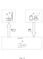
- FIG. FIG. 10 is a diagram illustrating a configuration example of an information processing system including an information processing apparatus according to a second embodiment;
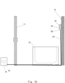
- 3 is a side view showing an installation example of an information processing device in the information processing system of FIG. 2;
- FIG. 3 is a block diagram showing a configuration example of an information processing device in the information processing system of FIG. 2;
- FIG. 3 is a schematic diagram for explaining an example of the flow of processing for generating and registering face model data in the information processing system of FIG. 2;
- FIG. 5 is a schematic diagram for explaining an example of face authentication processing in the information processing apparatus of FIG. 4 when the caregiver is not wearing a mask;
- FIG. 5 is a schematic diagram for explaining an example of face authentication processing in the information processing apparatus of FIG. 4 when a caregiver wears a mask
- FIG. 3 is a diagram for explaining an example of notification in a terminal device in the information processing system of FIG. 2
- FIG. 5 is a flowchart for explaining an example of face authentication processing in the information processing apparatus of FIG. 4
- FIG. 11 is a schematic diagram showing a configuration example of an information processing apparatus according to a third embodiment; It is a figure which shows an example of the hardware constitutions of an apparatus.
- FIG. 1 is a block diagram showing one configuration example of an information processing apparatus according to a first embodiment.
- the information processing device 1 can include a sensor 1a, an imaging device 1b, a determination unit 1c, a face authentication unit 1d, and an output unit 1e.
- the sensor 1a is a sensor that detects the entry of a person into a room to be monitored, and can be a human sensor provided at a position where entry can be detected.
- Various rooms such as a private toilet room and a bathroom can be applied as the room to be monitored.
- the person to be authenticated who is the person subject to room entry monitoring
- a care receiver that is, an example in which the room subject to room entry monitoring is the room used by the care receiver
- a person can also be subject to room entry monitoring.
- the person to be authenticated refers to a person whose face is authenticated by the face authentication unit 1d and the result of which is output.
- the care receiver can also be referred to as a care receiver, a care recipient, a care recipient, or the like.
- caregivers include caregivers, doctors, and the like, and can also be referred to as caregivers.
- the rooms to be monitored include the above-mentioned toilets and bathrooms.
- the information processing apparatus 1 can be used, for example, in facilities for the elderly, private homes, hospitals, etc. where it is necessary to watch over a person requiring care.
- the senor 1a examples include an infrared sensor and an optical sensor.
- the sensor 1a is not limited to infrared rays or the like, and may be a sensor using any method such as image identification, ultrasonic waves, or the like.
- the sensor 1a is preferably designed to be able to detect leaving after entering the room, and in a simple example, it can detect leaving the room when a person is detected after detecting entry.
- the imaging device 1b captures an image of the person who has entered the room to obtain image data.
- the imaging device 1b can be, for example, a camera that captures still images and/or moving images, and can be called a face authentication camera because the captured image data that is acquired is used in the face authentication unit 1d in the subsequent stage. Further, the imaging device 1b is not limited to a visible light camera, and may be an infrared light camera or the like.
- the judgment unit 1c judges whether or not the person who entered the room is wearing a mask based on the image data obtained by the image pickup device 1b, so that the person who entered the room is authenticated as the user of the room (user). It is tentatively determined whether the person is not the person (in this example, the person receiving care) or the person to be authenticated. Temporarily determining that the person is not a cared person by the determination unit 1c means tentatively determining that the person is a caregiver. Note that the determination unit 1c can also be configured to determine whether or not the person who has left the room is a care recipient.
- the face authentication unit 1d detects the person to be authenticated in the image data as a result of the provisional determination by the determination unit 1c (in this example, the person being cared for), that is, if the person is not wearing a mask. Face authentication processing is executed based on the face image data of. When the image data includes face image areas of a plurality of persons, the face authentication process may be executed based on the face image area data of all persons to be authenticated.
- the face authentication unit 1d preliminarily stores the face image data, each person to be authenticated (a care receiver in this example), and each attendant (a caregiver in this example) who may enter the room with the person to be authenticated.
- the above-described face authentication processing is executed by comparing with the stored feature data indicating facial features. Therefore, the face authentication unit 1d executes face authentication processing when the person is an attendant (a caregiver in this example) as a result of the temporary determination by the determination unit 1c, that is, when the person is wearing a mask. and terminate the subsequent processing.
- the above feature data can be, for example, data indicating feature points of the face.
- this comparison is performed by applying machine learning to a learning model (learned model) using learning data including feature data and original image data (face image data). It can also be run by typing
- the person who entered the target room is specified from the face image data of the person who has been provisionally identified as the person to be authenticated, that is, the individual who entered the target room is specified (identified )can do. Since the person identified here is the result of the above-described comparison, the person may be the attendant as a result of provisional determination.
- the face authentication unit 1d can also be called an identification unit because it identifies an individual in this way.
- the determination unit 1c and the face authentication unit 1d can partially include common components.
- the determination unit 1c can use intermediate data in recognition processing in the face authentication unit 1d. That is, the determination unit 1c can be included as part of the functions of the face authentication unit 1d.
- the user of the room can be assumed to be a person who is neither a care recipient nor a caregiver (for example, a family member who has come to visit), but for such a person, authentication fails as a result of face authentication processing. and can be judged as an unknown person.
- the output unit 1e outputs the result of the face authentication process to the notification destination.
- the output unit 1e can be, for example, a communication unit configured by a wired or wireless communication interface or the like.
- the output unit 1e can transmit information indicating the result of face authentication processing to a terminal device (not shown) of the notification destination via the communication unit.
- the output unit 1e can, for example, transmit this information to an external server (not shown) via the communication unit, so that the server can transfer the notification information to the terminal device of the notification destination.
- the notification destination can be set in advance, and it is preferable that the notification destination is changeable.
- the output unit 1e can output the result to the notification destination regardless of the result of the face authentication process.
- the output unit 1e excludes the face authentication process result for the attendant and outputs the face authentication process result to the notification destination. You can also That is, the output unit 1e can output the result to the notification destination when the person to be authenticated (in this example, the care recipient) is authenticated, and not output the result when the attendant is authenticated.
- the output unit 1e may or may not notify that an unknown person has entered the room. Just do it.
- the information processing apparatus 1 can also include a control unit (not shown), and this control unit can include the above-described determination unit 1c, face authentication unit 1d, and output unit 1e (or part thereof). can.
- This control unit can be implemented by, for example, a CPU (Central Processing Unit), a working memory, and a non-volatile storage device storing programs.
- This program executes the processing of inputting detection results from the sensor 1a, the processing of inputting image data captured by the imaging device 1b, and the processing of the determination unit 1c, the face authentication unit 1d, and the output unit 1e. It can be a program to be executed.
- the control unit provided in the information processing apparatus 1 can be realized by, for example, an integrated circuit.
- the storage device can also store a notification destination, and the output unit 1e can refer to the notification destination and output the result of the face authentication processing.
- the information processing device 1 is assumed to be configured as a single information processing device, but it can also be configured as a plurality of devices with distributed functions. In the latter case, each device is provided with a control unit, a communication unit, and if necessary a storage unit, etc., and these plural devices are connected as necessary by wireless or wired communication to cooperatively perform information processing. All that is necessary is to realize the function of the device 1 .
- This information processing method performs the following information processing.
- the sensor 1a detects the entry of a person into a room, and when the sensor 1a detects the entry of a person into the room, the imaging device 1b images the person entering the room to obtain image data. Furthermore, the above information processing is based on the image data obtained by the imaging device 1b, and determines whether or not the person who enters the room is wearing a mask. It is tentatively determined whether the person is not a person or a person to be authenticated.
- the result of the provisional determination is that the person is the person to be authenticated
- face authentication processing is executed based on the face image data of the person to be authenticated in the image data, and the result of the face authentication processing is obtained.
- Output to notification destination is performed by comparing the face image data with feature data indicating facial features stored in advance for each person to be authenticated and each attendant.
- the output to the notification destination can be executed by excluding the result of the face authentication process for the attendant.
- the program described above can be a program for causing a computer to execute the information processing described above.
- real-time and high-precision detection can be performed without reducing the processing capacity.
- real-time and high-precision detection can be performed without reducing the processing capacity.
- the feature data of the caregiver's face is pre-registered and the face authentication process is performed and the mask detection function is provided, space saving and power saving can be achieved by incorporating the information processing apparatus as an edge device.
- a highly accurate face recognition process can be realized even with a CPU.
- the caregiver when a caregiver wearing a mask enters the toilet to clean the toilet, etc., the caregiver is compared with the face authentication process and the processing is performed. It can be excluded from the target of face authentication simply by performing a light mask determination process. Therefore, in the present embodiment, even when a plurality of caregivers assist one user, face authentication processing can be performed without greatly impairing performance. Further, in this embodiment, it is also possible to employ a configuration in which notification is not performed even when a caregiver not wearing a mask enters the room.
- FIG. 2 is a diagram showing a configuration example of an information processing system including an information processing apparatus according to the second embodiment
- FIG. 3 is a side view showing an installation example of the information processing apparatus in the information processing system of FIG.
- the information processing system according to the present embodiment (hereinafter referred to as this system) can be a system in which a part thereof is installed in a toilet and notifies a notification destination (for example, a caregiver, etc.). explain.
- the system includes an information processing device 60 attached to the toilet bowl 10, a server 40 wirelessly connected to the information processing device 60, and a terminal device 50 wirelessly connected to the server 40. be able to. These connections can be made within one wireless LAN (Local Area Network), for example.
- the system can be configured so that the information processing device 60 can directly transmit information to the terminal device 50 .
- the information processing device 60 is installed in the toilet bowl 10 of the toilet and also acquires excretion information will be described. If the unit is installed in the toilet bowl 10, excretion information can be obtained.
- the toilet bowl 10 can have an edge portion 10c for forming a water-retaining portion with the side surface 10a, and can also have a flat portion 10b continuing from the edge portion 10c.
- the flat portion 10b can be provided with a toilet seat 11 having a toilet seat body 11a equipped with, for example, a warm water washing function for user washing, and a toilet seat cover 11b for covering the toilet seat body 11a.
- the information processing device 60 can be a toilet-installed type (toilet-installed type in this example) device, and notifies the terminal device 50 directly of a detection event such as a detection event that detects the entry of the care-receiver into the room. Or through the server 40 .
- a detection event such as a detection event that detects the entry of the care-receiver into the room. Or through the server 40 .
- the information processing device 60 is an excretion information collection device having a function of acquiring excretion information will be described. In this case, an event related to excretion such as the start or end of excretion can also be notified as a detection event.
- the information processing device 60 can also be configured to record excrement, present excrement information (notification, etc.), and predict excretion in cooperation with the server 40 and the terminal device 50 .
- the information processing device 60 and the toilet bowl 10 can constitute, for example, a toilet bowl with a function of outputting excretion information.
- the shape of the information processing device 60 is not limited to the shape shown in FIG. Also, part of the functions of the information processing device 60 can be provided on the toilet seat body 11a side.
- the information processing device 60 is an example of the information processing device 1 in FIG.
- main components including components corresponding to each part of the information processing device 1 in FIG. 1 will be briefly described.
- the information processing device 60 includes a human sensor 24, an imaging device 25, an information collection unit 26, a storage housing 61, a bridge unit 62, an inner housing 63, a control A portion 67, a separate housing 68, and an outer housing 69 may be provided.
- the human detection sensor 24 is an example of the sensor 1a, and is a sensor that detects a person who enters the private room of the toilet, such as a user (user) of the toilet bowl 10. Examples thereof include an infrared sensor and an optical sensor. be done.
- the imaging device 25 is an example of the imaging device 1b, and is a device that captures the face of a person who enters the private room of the toilet, such as a user of the toilet. authentication camera). Further, the imaging device 25 is not limited to a visible light camera, and may be an infrared light camera or the like.
- the information collection unit 26 is assumed to be arranged in the inner casing 63 . However, the information collection surface of the information collection unit 26 is exposed from the opening of the inner housing 63, so that information can be collected from the pooled portion of the toilet bowl 10 (the area where excrement is excreted).
- An information collection unit 26 is provided.
- the information collecting surface corresponds to a lens surface when the information collecting unit 26 is a camera, and a detection surface when the information collecting unit 26 is a sensor.
- the information collecting unit 26 is a part that collects excrement information in the toilet bowl 10.
- an imaging device that collects excrement content such as the shape and color of the excrement through an optical lens or an optical distance sensor. can be used as a distance sensor or the like for measuring .
- Excretion information can be information indicating the content of excretion, and in a simpler example, can be information indicating whether the excrement is stool (feces) or urine (urine).
- the excrement information can also include other information such as information indicating the color of the excrement and, if the excrement is solid, its shape.
- the information collecting unit 26 may simply be configured to detect and collect the presence or absence of excretion as excrement information.
- the information collecting unit 26 can set the collection range as an area (excretion range) that includes the water-stagnation part of the toilet bowl, and this excretion range can also be referred to as the scheduled excretion range.
- this excretion range can also be referred to as the scheduled excretion range.
- the information collecting unit 26, the motion sensor 24, and the imaging device 25 are connected to the control unit 67 by wire or wireless communication.
- FIG. 2 shows an example in which the information collecting unit 26 is connected to the control unit 67 via the cable K1, and the human sensor 24 and the imaging device 25 are connected to the control unit 67 via the cable K2.
- the control unit 67 controls the human sensor 24, the imaging device 25, and the information collection unit 26.
- the control unit 67 can receive the detection result of the human sensor 24, can instruct the imaging device 25 to take an image, can receive the imaged image, and can send the information of the excrement to the information collecting unit 26. may be instructed to collect or receive the information collected.
- the control unit 67 can be configured to execute the functions of the determination unit 1c, the face authentication unit 1d, and the output unit 1e.
- the control unit 67 can be implemented by, for example, a CPU, a working memory, and a nonvolatile storage device that stores programs. This program can be, for example, a program for causing the CPU to execute the processes described above.
- the controller 67 can be realized by an integrated circuit, for example.
- the storage housing 61 is a housing arranged outside the toilet bowl 10 that houses the control unit 67, and will be described as a control box 61 hereinafter.
- a bridging portion (crossing) 62 is a portion that bridges the inner housing 63 and the outer housing 69 . That is, the crossover 62 is a mechanism that connects the inner housing 63 and the outer housing 69 and is installed on the edge 10 c of the toilet bowl 10 .
- the outer housing 69 is a housing provided with a clamping mechanism for fixing the inner housing 63 and the toilet bowl 10 .
- the outer housing 69 is a housing arranged outside the toilet bowl 10, and its shape does not matter as long as it does not interfere with excretion.
- the above-described clamping mechanism clamps the inner housing 63 and the outer housing 69 by adjusting the distance between the inner side of the edge 10c via the crossover 62, for example. It can be a mechanism for fixing to the portion 10c. Accordingly, the inner housing 63 of the information processing device 60 can be securely fixed and installed regardless of the shape of the toilet bowl 10 such as the shape of the edge portion 10c. Moreover, as long as it is such a mechanism, the shape and components of the fixing clamp mechanism are not limited.
- a securing clamping mechanism may be provided with its main components on the outer housing 69 .
- the inner housing 63 is a housing in which the information collecting unit 26 is arranged, and will be described as a sensor box 63 hereinafter.
- the sensor box 63 has, for example, an optical sensor for collecting excrement information, and is arranged inside the toilet bowl 10 .
- the separate housing 68 is a housing in which the human sensor 24 and the imaging device 25 are arranged.
- the separate housing 68 has a human sensor 24 for human detection and an imaging device (camera) 25 for face authentication installed inside or partly outside.
- the human detection/identification box 68 can also be equipped with a camera adjustment mechanism that adjusts the orientation of the camera in the horizontal direction.
- the imaging device 25 can have the lens exposed from the human detection/identification box 68 so that the face of the toilet user can be imaged, but it is sufficient if the face can be imaged.
- the human sensor 24 may have its detection surface exposed from the human detection/identification box 68 so as to detect the user of the restroom, but it is sufficient if the human can be detected. Also, if the human sensor 24 and the imaging device 25 are connected to the control unit 67 by wired or wireless communication, information can be sent and received.
- the human detection/identification box 68 can be arranged at a position spaced apart from the control box 61 and the toilet bowl 10, as illustrated in FIGS. 2 and 3 show an example in which the human detection/identification box 68 is installed on the wall W of the toilet where the toilet bowl 10 is installed.
- the human detection/identification box 68 can be installed on the ceiling of the room, a shelf installed in the room, or the like, in addition to the wall W.
- the human detection/identification box 68 can adopt a wired connection with the control box 61 using a cable K2 or a wireless connection, and in either case, it can be used at a position separated from the control box 61. ing.
- the human detection/identification box 68 can be rotated horizontally and provided with a mechanism to fix the orientation of the rotating box.
- the human sensor 24 and the imaging device 25 are preferably arranged so that the detection surface and the imaging lens are positioned at least at a position higher than the crossing 62 in order to facilitate detection and imaging of a person. . Moreover, it is more preferable to provide the detection surface and the imaging lens at a position higher by a predetermined height considering the height of the toilet seat 11 .
- the control box 61 having the human detection/identification box 68 and the control unit 67 and the sensor box 63 having the function of collecting excretion information are connected by cables K1 and K2.
- the human detection/identification box 68 is arranged on the wall W of the toilet and the box having the controller 67 is arranged on the side of the toilet bowl 10, the installation work is easy.
- the control box 61 can be arranged on the back side of the toilet bowl 10, and the installation work in this case is easy.
- both cables K1 and K2 desirably include a power supply line for supplying power from the control box 61 . Power is supplied to the control box 61 from a power cable (not shown).
- FIG. 2 assumes that the cable K1 passes through the crossover 62, the cable K1 is connected to the information collecting unit 26, led out from the sensor box 62, and directly connected to the control box 61. It is also possible to be In that case, the cable K1 passes through the upper surface of the edge 10c of the toilet bowl 10 (passes between the upper surface of the edge 10c and the toilet seat body 11a).
- the server 40 can include a control unit 41 that controls its entirety, and a storage unit 42 that stores, for example, notification conditions and various acquired information (and information generated based thereon).
- the control unit 41 can be configured to transfer the notification to the terminal device 50 as part of the function of the output unit 1e in FIG.
- the storage unit 42 can store, as notification conditions, a notification destination for each detected event and for each person being assisted as a user.
- the server 40 having a part of the functions of the output unit 1e can output to the notification destination according to the occurrence of the detection event according to the notification conditions.
- the number of notification destinations to which a certain detection event is notified may be one, but may be plural.
- the server 40 preferably has a setting unit for setting the notification conditions from an external device such as the terminal device 50, so that the notification conditions can be set according to the operation mode.
- the control unit 41 can be implemented by, for example, a CPU, a working memory, and a non-volatile storage device that stores programs. Also, the controller 41 can be realized by an integrated circuit, for example. This storage device can also be used as the storage unit 42, and this program can be a program for causing the CPU to implement the functions of the server 40. FIG.
- the terminal device 50 is a terminal device possessed by a caregiver who takes care of (will be cared for) a care recipient as a user of the toilet, and can be a portable information processing device.
- the terminal device 50 can be a smart device such as a mobile phone (including what is called a smart phone), a tablet, or a mobile PC, but it can also be an electronic bulletin board.
- the terminal device 50 can also include a control unit that controls the entire device and a storage unit. etc. can be realized.
- the program stored in this storage device can be a program for causing the CPU to implement the functions of the terminal device 50 .
- FIG. 4 is a block diagram showing a configuration example of an information processing device in the information processing system of FIG.
- the information processing device 60 can be composed of two devices as shown in FIGS. 2 and 3, for example.
- the information processing device 60 can also be called a "toilet sensor” or a “toilet sensor device” because it has various sensors installed in the toilet.
- the toilet sensor corresponds to a so-called edge in this system that monitors the use of the toilet by the care recipient via a communication network.
- control box 61 can house a CPU 27a, a connector 27b, USB I/Fs 27c and 27d, and a WiFi module 27e.
- USB is an abbreviation for Universal Serial Bus, and both USB and WiFi are registered trademarks (same below).
- the control box 61 may be directly connected to the CPU 27a without having various I/Fs and connectors.
- control box 61 and the sensor box 63 are connected by an interface exemplified by the connector 27b and USB I/F 27c, and the connection line is housed in the cable K1.
- a portion of the cable K1 passes through the interior of the jumper 62 (and the outer housing 69).
- control box 61 and the human detection/identification box 68 are connected by an interface exemplified by the connector 27b and USB I/F 27d, and the connection line is housed in the cable K2.
- the information processing device 60 is equipped with substrates, cables connecting them, etc. in each box and crossover 62 .
- the information processing device 60 adopts the divided box configuration as described above and optimizes the orientation of the connector for connecting the cable, thereby reducing the space required for the excess length of the cable and reducing the size of the board and mounted components. can be planned.
- the width of each structure can be reduced by dividing the placement locations of the respective boxes.
- the sensor box 63 can store, for example, a distance sensor 26a that functions as a seating sensor that detects sitting on the toilet seat 11, and a first camera 26b that captures excrement.
- the CPU 27 a is an example of a main control unit of the information processing device 60 and controls the entire information processing device 60 .
- the connector 27b connects the human sensor 24 and the distance sensor 26a to the CPU 27a.
- the USB I/F 27c connects the first camera 26b and the CPU 27a, and the USB I/F 27d connects the second camera 25 and the CPU 27a.
- the distance sensor 26a is a sensor that measures the distance to an object (the buttocks of the user of the toilet bowl 10) and detects that the user has sat on the toilet seat 11. When the threshold value is exceeded and a certain period of time elapses, , it is detected that the object is seated on the toilet seat 11 . Further, the distance sensor 26a detects that the user has left the toilet seat 11 when the distance to the object changes after being seated.
- the distance sensor 26a for example, an infrared sensor, an ultrasonic sensor, an optical sensor, or the like can be adopted.
- a transmitting/receiving element may be arranged so that light (not limited to visible light) can be transmitted/received through a hole provided in the sensor box 63 .
- the transmitting/receiving element here may be composed of a transmitting element and a receiving element separately, or may be integrated.
- the distance sensor 26a is connected to the CPU 27a via a connector 27b so that the detection result can be transmitted to the CPU 27a side. Based on this detection result, the CPU 27a can obtain seat leaving/seating data indicating the seat leaving/seating information of a person, and can also transmit the data to the server 40 side via the WiFi module 27e.
- the first camera 26b is an example of a camera that captures image data from which excretion information is obtained, and can be an optical camera with a lens portion arranged in a hole provided in the sensor box 63.
- the first camera 26b is installed so as to include the excretion range of excrement in the toilet bowl 10 of the toilet in the imaging range.
- the first camera 26b is connected to the CPU 27a via the USB I/F 27c, and transmits imaging data to the CPU 27a side.
- the human sensor 24 is an example of the sensor 1a, and is a sensor that detects the presence of a person (entering/leaving the room) in a specific area (measurement area range of the human sensor 24) that is part of the toilet room. Yes, it can be called an entrance/exit sensor.
- the human sensor 24 can employ, for example, an infrared sensor, an ultrasonic sensor, an optical sensor, etc., regardless of its detection method.
- the human sensor 24 is connected to the CPU 27a via a connector 27b, and when detecting a person in the specific area, transmits the detection result to the CPU 27a. This detection result can also be transmitted to the server 40 via the WiFi module 27e by the CPU 27a.
- the second camera 25 is an example of the imaging device 1b, and can be an optical camera, and is a face authentication camera that obtains face image data by photographing a face image of a user, etc., in order to identify the user of the toilet.
- the second camera 25 can be installed in the toilet room (toilet room) in which the toilet bowl 10 is installed.
- face authentication processing is performed using face image data captured by the second camera 25.
- FIG. In this system, when the human detection sensor 24 detects a person, processing can be performed so that the second camera 25 photographs the target person who has entered the restroom. can be implemented.
- the WiFi module 27e is an example of a communication device that transmits various types of acquired data to the server 40, and can be replaced with modules that adopt other communication standards. Data to be transmitted can be transmitted to the server 40 by the CPU 27a via the WiFi module 27e. Note that face image data acquired by the second camera 25 is basically not transmitted in order to reduce the amount of data and in consideration of privacy.
- the CPU 27a determines whether or not the person entering the room is wearing a mask. It is tentatively determined whether the person is not or is the care recipient. Being provisionally determined as not being a cared person means being provisionally determined as being a caregiver.
- the CPU 27a executes face authentication processing based on the face image data of the cared person in the image data. do.
- the face authentication process may be performed based on the face image area data of the care receiver among all persons.
- the face authentication processing is performed by comparing face image data with feature data indicating facial features stored in advance for each care recipient and for each caregiver who may accompany the care recipient into the room. executed. Therefore, in the face authentication process, if the result of provisional determination is that the person is a caregiver, that is, if the person is wearing a mask, the face authentication process is not executed, and the subsequent processes are terminated.
- the above feature data can be, for example, data indicating feature points of the face.
- the feature data described above can be data generated from face image data acquired by a terminal device such as the terminal device 50 and stored in a storage device inside the information processing device 60 .
- this internal storage device may be connected to the CPU 27a, or may be provided inside the CPU 27a.
- this comparison is performed by applying machine learning to a learning model (learned model) using learning data including feature data and original image data (face image data). It can also be run by typing
- the face recognition processing it is possible to identify a person who has entered the target room from the face image data of the person temporarily determined to be the person receiving care. )can do. Since the person identified here is the result of the above-described comparison, there are cases where the person is provisionally determined to be a caregiver, but in that case, the face authentication result may not be output.
- the user of the room can be assumed to be a person who is neither a care recipient nor a caregiver (for example, a family member who has come to visit), but for such a person, authentication fails as a result of face authentication processing. , the person can be judged as an unknown person, and this fact may also be notified. In consideration of privacy, it is preferable not to store the face image data captured by the second camera 25 after face authentication processing.
- the CPU 27a and WiFi module 27e can be an example of the output unit 1e in FIG. Also, the CPU 27a outputs the result of the face authentication process to the notification destination via the WiFi module 27e. Further, when the caregiver is authenticated by the face authentication process, the CPU 27a can output the result of the face authentication process to the notification destination while excluding the result of the face authentication process for the caregiver. If the result of the face authentication process is that the person is an unknown person, the CPU 27a may or may not notify that the unknown person has entered the room. should be determined in advance.
- the CPU 27a can handle the main processing of detecting detection events indicated by the results of face authentication processing, excretion information, and seat leaving information.
- the notification destination can be the terminal device 50 held by one or more of the helpers, and the notification condition can include which helper is the notification destination.
- the caregiver can be notified by displaying and/or outputting audio on the terminal device 50 .
- the terminal device 50 has been described assuming that it is a smart device, but it may be a device that only emits a sound when a notification is received, or an electronic bulletin board that displays room entry, personal name, and the like.
- the notification destination is, in addition to or instead of the terminal device 50, for example, a notification device of a nurse call system, another terminal device owned by a caregiver other than the terminal device 50 (for example, PHS: Personal Handy-phone System), It may be an intercom or the like.
- a notification device of a nurse call system for example, a notification device of a nurse call system, another terminal device owned by a caregiver other than the terminal device 50 (for example, PHS: Personal Handy-phone System), It may be an intercom or the like.
- the CPU 27a, USB I/F 27c, WiFi module 27e, and server 40 obtain the excretion information based on the imaging data captured by the first camera 26b.
- the server 40 can carry out the main processing of obtaining the excretion information from the imaging data.
- the CPU 27a can also be configured to handle this processing.
- the server 40 or the CPU 27a has an analysis unit that analyzes the excretion information based on the imaging data obtained by the first camera 26b. This analysis unit analyzes the excretion information when the care recipient can be authenticated as a result of the face authentication process, that is, when the person entering the room is identified and the person is the care recipient. Imaging by the first camera 26b can also be performed only when the result of such face authentication processing is obtained.
- the server 40 mainly obtains, as a part of the excretion information, information indicating whether or not the captured image data includes a foreign body, which is an object other than excrement, as a subject other than the toilet bowl and its cleaning liquid.
- the foreign matter can also be called other objects, and may be liquid or solid as long as it is other than excrement, such as vomit, melena, blood vomiting (hematemesis), diapers, urine pads, toilet paper cores, etc.
- the server 40 can also be configured to obtain the shape, color, and amount of the excrement as the excretion information when the excrement is not a foreign object. Further, the CPU 27a and the WiFi module 27e or the server 40 can also notify the notification destination of the analysis result of the analysis unit.
- the notification destination in this case may be different from the notification destination of the result of the face authentication processing, and which notification destination should be stored in the storage device in the information processing device 60 or the storage unit 42 as a notification condition, for example. Just do it.
- information such as excretion information and seat leaving information can be stored by the server 40 in the storage unit 42 or the like, and can be output by the server 40 in response to access from the terminal device 50, for example.
- the server 40 has a function of generating an excretion diary. You will be able to view the excretion diary whenever you want.
- the excretion diary includes the date and time of the excretion action, and this date and time includes the date and time of capturing the image data of excrement, the date and time of subject identification, the date and time of entering and leaving the room, the date and time of sitting, the date and time of leaving, and from sitting to leaving. It can be obtained by any of the date and time in the middle of .
- FIG. 5 is a schematic diagram for explaining an example of the flow of face model data generation and registration processing in the information processing system of FIG.
- the face photograph used to generate the face model data can be imaging data obtained by photographing the caregiver or the care-receiver with a terminal such as the terminal device 50 .
- This terminal transmits the obtained imaging data to the server 40 on the cloud, and the server 40 generates face model data for face authentication from the imaging data.
- the face model data can be data containing information obtained by extracting features such as eyes, mouth, nose, and outline from a photograph of the face.
- the cared person himself/herself can take a photograph of his/her own face with a terminal equivalent to the terminal device 50 and transmit the photographed data to the server 40 so that the server 40 can generate face model data.
- the server 40 transmits the generated face model data to the information processing device 60, and the information processing device 60 registers, that is, installs the face model data so that it can be referred to during face authentication processing. Hold.
- data is transmitted from the server 40 to the information processing device 60, it is possible to transmit only the modeled data without transmitting the image data such as the face photograph itself.
- the generation of face model data can also be executed by a server other than the server 40.
- the generation of face model data if the face model data can be generated by a terminal such as the terminal device 50 that has photographed the face, the data generated by the terminal can be directly generated without using a server such as the server 40. It is also possible to transmit to the information processing device 60 .
- FIG. 6 is a schematic diagram for explaining an example of face authentication processing in the information processing device 60 when the caregiver is not wearing a mask.
- FIG. 7 is a schematic diagram for explaining an example of face authentication processing in the information processing device 60 when the caregiver wears a mask.
- FIG. 6 shows an outline of the face authentication function when the caregiver does not wear a mask.
- the CPU 27a receives the detection result from the human sensor 24 and detects that the user has entered the toilet
- the second camera 25 is activated for face authentication, and the image pickup range of the second camera 25 is detected.
- the detected face is surrounded by a rectangle.
- the face areas of the care receiver and caregiver are surrounded by rectangles fa1 and fa2, respectively, in the imaging data.
- the CPU 27a performs face authentication processing by matching the detected face areas fa1 and fa2 with the face model data, as shown in the image FR1 of FIG.
- the CPU 27a finds the caregiver as a result of the face authentication process (in this example, when the face region fa2 is found to be the face of the caregiver), the caregiver is within the imaging range of the second camera 25. Even if there is, the area fa2 of the face is excluded from face authentication as shown by the image FR2 in FIG.
- Determination of being a caregiver can be made, for example, by first detecting certain feature points in the caregiver's face model data. These feature points can be registered in advance as feature points such as hats, hairpins, and hairstyles.
- the CPU 27a can specify that this face is the care-receiver A by performing face authentication processing on the face area fa1 in the image FR2.
- the CPU 27a receives the detection result from the human detection sensor 24 and detects that the user has entered the toilet, face authentication is performed. Therefore, the second camera 25 is activated, the imaging range of the second camera 25 is scanned, and when a face is detected, the detected face is surrounded by a rectangle. As a result, as shown in the image FD of FIG. 7, the face areas of the care recipient and caregiver are surrounded by rectangles fa1 and fa2, respectively, in the imaging data.
- the CPU 27a determines that the mask is surrounded by a rectangle (rectangular area ma2 in this case) and that the mask is worn, as shown in the image MD of FIG. judge.
- the CPU 27a determines that the person is wearing a mask, that is, the caregiver as a result of the mask wearing determination, even if the caregiver is within the imaging range of the second camera 25, the face area fa2 is As shown by the image FR in FIG. 7, the face recognition is excluded, and the face is not matched.
- the CPU 27a performs face authentication processing for matching face model data with the mask-unwearing face region fa1 in the image FR of FIG. can be done.
- the rectangular area is actually enclosed in FIGS. 6 and 7, it is sufficient if the rectangular area can be detected and specified.
- shape of the face it is possible to adopt other shapes such as an ellipse instead of a rectangle.
- the mask may have other shapes such as a polygon with pentagons or more, an ellipse, etc., instead of a rectangle.
- FIG. 8 is a diagram for explaining an example of notification by a terminal device in the information processing system of FIG.
- the terminal device 50 can notify notification information 52 to 54 in that order on its display screen 51 .
- the notification information 52 is an example of notification information that notifies the care receiver of entering the toilet when the person is detected by the human sensor 24 and the person is tentatively determined to be the care receiver.
- the notification destination even when it is detected that the care-receiver has entered the room, that is, the entry of a person not wearing a mask may be notified to the notification destination.
- notification information 53 notified as a result of face authentication processing indicates that the person who entered the room is the user (in this example, the care recipient PA) as a result of identifying the user by face authentication processing.
- notification information for notifying that It should be noted that it is possible to know that the person is Mr. PA by associating the name with the face model data.
- Mr. PA when it is detected that Mr. PA has left the room, it can be configured to display the notification information 54 to that effect. Also, after the notification information 52 is notified, when it is detected by face authentication processing that the person entering the room is a caregiver, the individual name of the caregiver (for example, Mr. C) can be notified. does not have to be done. As an alternative process, in that case, it is also possible to issue a notification excluding the result of the face authentication process, that is, simply issue a notification that the person entering the room was a caregiver.
- FIG. 9 is a flowchart for explaining an example of face authentication processing in the information processing device 60. As shown in FIG. The processing in the information processing device 60 is mainly executed by the CPU 27a.
- the information processing device 60 monitors whether or not the human sensor 24, which functions as a room entry sensor, has reacted (step S1). is activated (step S2). If NO in step S1, that is, if the human sensor 24 does not respond, the process waits until it responds.
- step S1 when the person requiring care enters the toilet, YES is obtained in step S1, and the second camera 25 is activated.
- the activated second camera captures an image of a person who has entered the room, the CPU 27a or the main body of the second camera 25 performs processing for detecting a face within the imaging range, and determines whether or not a face has been detected (step S3).
- step S3 as illustrated in FIGS. 6 and 7, when the second camera 25 detects a face, the detected face is surrounded by a rectangle.
- the determination in step S3 is performed while changing the imaging range of the second camera 25 as necessary and performing imaging until the face is detected.
- step S3 is executed until a face is detected, the process can be ended after a predetermined time has passed, for example.
- the CPU 27a performs mask detection by determining whether or not a mask is worn on the face area detected in step S3 (step S4). If YES in step S4, that is, if mask wearing is detected, the CPU 27a determines that the person is a caregiver, ends the face authentication processing, and does not perform any further authentication processing on the face image of the target. . On the other hand, if NO in step S4, that is, if the mask is not worn, the CPU 27a collates the face area (image data of the face area) with the face model data (step S5). At the time of matching, it is also possible to generate face model data for the image data of the face region in the same manner as when generating the face model data, and compare the two.
- step S5 the CPU 27a determines whether the image data of the face area matches or corresponds to registered face model data (also simply referred to as face data) (step S6). In the case of YES in step S6, the CPU 27a determines whether the user is a care recipient or a caregiver (step S7). When the CPU 27a determines that the person is the caregiver in step S7, the process ends. On the other hand, when the CPU 27a determines that the user is the user in step S7, the CPU 27a executes notification of the person entering the room and analysis of the excrement in cooperation with the notification function and the excrement analysis function to process excretion information notification. is performed (step S8), and the process ends. Cooperation in step S8 can also include cooperation with the server 40 .
- step S6 If NO in step S6, that is, if the image data of the face region is unregistered or registered but cannot be verified, the CPU 27a treats the person entering the room as unknown (step S9), and the notification function and the It cooperates with the excreta analysis function (step S8) and ends the process. It should be noted that after the process of step S9, the process can be terminated without performing such cooperation. In this way, in the information processing device 60, when the specified occupant is a user, analysis and notification of excrement indicating the toilet use state of the user (analysis of the user's state and notification to the caregiver) are performed. Can be linked with processing.
- this system has been explained on the premise that there is only one toilet bowl 10 (only one toilet room). However, in this system, it is preferable to obtain the results of face authentication and the like for detection of detection events for a plurality of restrooms. This makes it possible to apply this system even when there is a possibility that a certain care recipient uses two or more toilets.
- server 40 can be installed in a facility such as a hospital, and can be installed in a private residence or an apartment complex for personal use. In either case, server 40 may also be a cloud server, as described above.
- the program of the terminal device 50 can be executablely incorporated into the terminal device 50 as care software including a notification function of notification information.
- the terminal device 50 can also directly (or directly and automatically) receive and store information obtained on the toilet side of the information processing device 60 or the like.
- Various information recorded by the server 40 can also be received and stored.
- the information processing device 60 can be configured to notify the terminal device 50. That is, it is also possible to adopt a configuration in which the information detected by the information processing device 60 is directly notified to the terminal device 50 of the caregiver.
- Bluetooth registered trademark
- ZigBee registered trademark
- notification can be made using a communication network using Wi-Fi, LTE, or the like.
- the information processing device 60 As described above, in this system, it is possible to perform face authentication processing based on information acquired by the information processing device 60, which corresponds to the so-called edge of the communication network, and watch over the person requiring care in nursing care facilities and residences. .
- the information processing device 60 is installed in a toilet where entry detection is desired.
- the information processing device 60 detects entry into the room by the human sensor 24, executes mask determination processing and face authentication processing, and if the person is a care recipient, enters the room and identifies the terminal device 50 as a result of face authentication. It is possible to notify the information indicating the cared person who received the care.
- the face model data used for face authentication is stored in a server on the cloud or the like, and the information processing device 60 acquires and holds the face model data in advance using a communication function.
- the information processing device 60 detects a person by the human sensor 24 serving as an entry/exit sensor to detect entry and exit from the restroom.
- the second camera 25 for face authentication takes an image of the person entering the toilet and compares the image with the face model data held in the device. By extracting the closest person, face recognition processing is performed to identify the person who has entered the room. Taking privacy into consideration, the photographed data is not saved.
- the information processing device 60 uses the distance sensor 26a, the first camera 26b, the human sensor 24, and the second camera 25 for face recognition to detect the location of the toilet where the user entered the room, the name of the user, the entry/exit time, and the seating position on the toilet seat. - It can also be configured to acquire information such as leaving. In that case, the information processing device 60 can transmit the acquired information to the server 40 via the WiFi module 27e and notify the terminal device 50 of the caregiver via the server 40 . At this time, the image data captured by the first camera 26b for excrement and the second camera 25 for face authentication may not be transmitted to the server 40.
- the above problem (1) can be solved as follows.
- the information processing device 60 is preloaded with face model data of the user and caregiver. Then, in the information processing device 60, the face model data and the face photographed by the face authentication camera are compared, and if the person who entered the room can be identified as a caregiver, the person is thereafter within the imaging range of the face authentication camera. If there is, it is not subject to face recognition. As a result, only the user can be targeted for face authentication processing, so that it is possible to improve the accuracy of person identification without lowering the processing performance of face authentication.
- the above problem (2) is solved as follows.
- the information processing apparatus 60 detects that a person has entered the toilet, the information processing apparatus 60 performs a person's face detection process, and performs a mask detection process on the detected face. By performing the mask detection process, it becomes possible to exclude caregivers wearing a mask from the target of the face authentication process, and face authentication can be performed only for the face not wearing the mask.
- the present embodiment even if the user and the caregiver are within the imaging range of the face recognition camera, face recognition can be performed only for the user by embedding the caregiver's face model data and mask detection processing as described above. Therefore, it is possible to improve the accuracy of person identification without reducing the processing performance of face recognition. That is, even if the CPU 27a is a powerless information processing apparatus 60 that is a space-saving and power-saving CPU, the user's face can be authenticated without lowering the processing performance and authentication accuracy. As a result, in this embodiment, it is possible to reduce the burden on the caregiver and provide generous support to the user. In addition, in this embodiment, caregivers can be excluded from face authentication, so cases such as toilet cleaning by caregivers can be excluded. In addition, regarding excretion management, which places a heavy burden on caregivers, it is possible to reduce the burden of assisting work by linking toilet entrance/exit management using face authentication processing and the excretion analysis function.
- this system enables real-time user identification with high accuracy and reduced performance degradation, reducing the burden on caregivers and providing generous support to users. That is, this system has the effects described in the first embodiment, and particularly has the following effects.
- the first effect is that by registering caregivers in advance, it is possible to reduce false detection of caregivers as users, and by inserting mask detection processing, when caregivers wear masks is the point where the effect of further improvement in accuracy can be obtained.
- the second effect is that the mask detection process is lighter than the face authentication process, so even when multiple caregivers assist one user, the user can be identified by face authentication without significantly impairing performance. is a point that can be realized.
- the third effect is that mask detection processing excludes caregivers wearing masks from facial recognition, so caregivers can be excluded from using the toilet when cleaning the toilet.
- FIG. 10 is a schematic diagram showing a configuration example of an information processing apparatus according to the third embodiment.
- the information processing apparatus does not require a portion related to excretion information in the information processing apparatus 60 according to the second embodiment.
- the information processing apparatus according to this embodiment includes a control box 61 and a human detection/identification box 68 connected to the control box 61 via a cable K2. Note that the server 40 and the terminal device 50 are omitted in FIG.
- the human detection/identification box 68 can be provided inside the bathroom, or placed outside the bathroom at a position where it can detect the entry of a person through the door 71 .
- FIG. 10 shows an example in which the human detection/identification box 68 is provided on the far side of the bathtub 70 of the bathroom as viewed from the door 71 .
- the control box 61 can also be provided inside the bathroom, but can also be provided outside the bathroom.
- the person detection/identification box 68 can be installed in rooms other than the toilet and bathroom, such as the entrance of the facility, the bedroom, the dining room, etc., to watch over the care recipient.
- the person detection/identification box 68 can also be used in hospitals, food handling companies, kindergartens, schools, etc. where there are many mask wearers and there is concern about information being leaked to networks. For example, by installing a face authentication camera in a cafeteria and identifying a visitor to the cafeteria by face authentication processing, it is possible to prepare a meal suitable for the user.
- a face recognition camera at the entrance of the facility, it is possible to prevent the person to be authenticated from going out alone by notifying other people or issuing an alarm on the terminal of the person to be authenticated. You can also In any installation example, it is possible to perform operation in which the identification of the facility user is linked to the recording of other work such as nursing care.
- FIG. 11 is a diagram showing an example of the hardware configuration of the device. The same applies to the other embodiment [a] above.
- a device 100 shown in FIG. 11 can have a processor 101 , a memory 102 and a communication interface (I/F) 103 .
- the processor 101 may be, for example, a microprocessor, an MPU (Micro Processor Unit), or a CPU.
- Processor 101 may include multiple processors.
- the memory 102 is configured by, for example, a combination of volatile memory and non-volatile memory.
- the functions of each device described in the first to third embodiments are realized by the processor 101 reading and executing a program stored in the memory 102 . At this time, information can be sent and received to and from other devices via the communication interface 103 or an input/output interface (not shown).
- a program includes a set of instructions (or software code) that, when read into a computer, cause the computer to perform one or more of the functions described in the embodiments.
- the program may be stored in a non-transitory computer-readable medium or tangible storage medium.
- computer readable media or tangible storage media may include random-access memory (RAM), read-only memory (ROM), flash memory, solid-state drives (SSD) or other memory technology, CDs - ROM, digital versatile disc (DVD), Blu-ray disc or other optical disc storage, magnetic cassette, magnetic tape, magnetic disc storage or other magnetic storage device.
- the program may be transmitted on a transitory computer-readable medium or communication medium.
- transitory computer readable media or communication media include electrical, optical, acoustic, or other forms of propagated signals.
- Appendix 1 a sensor that detects the entry of a person into a room; an imaging device for obtaining image data by imaging a person who has entered the room when the sensor detects that a person has entered the room; Based on the image data obtained by the imaging device, it is determined whether or not the person entering the room is wearing a mask, thereby determining whether the person entering the room is an authentication subject as a user of the room.
- a determination unit that temporarily determines whether the A face authentication unit that executes face authentication processing based on face image data of the authentication target person in the image data when the authentication target person is determined as a result of the provisional determination by the determination unit; an output unit that outputs the result of the face authentication process to a notification destination; with The face authentication unit compares the face image data with feature data indicating facial features stored in advance for each person to be authenticated and for each attendant who may enter the room with the person to be authenticated. to execute the face authentication process, Information processing equipment. (Appendix 2) When the attendant is authenticated as a result of the face authentication process, the output unit excludes the result of the face authentication process for the attendant and outputs the result.
- the information processing device according to appendix 1.
- the feature data is data generated from face image data acquired by a terminal device and stored in the information processing device.
- the information processing device according to appendix 1 or 2.
- the room is a toilet
- the imaging device is installed in the room of the toilet
- the information processing device analyzes the excretion information indicating the contents of excretion based on imaging data captured by another imaging device installed so as to include the excretion range of excrement in the toilet bowl in the imaging range. having a department
- the analysis unit analyzes the excretion information when the person to be authenticated can be authenticated as a result of the face authentication process
- the output unit outputs the analysis result of the analysis unit to a notification destination.
- the information processing apparatus according to any one of Appendices 1 to 3.
- a sensor detects the entry of a person into the room, when the sensor detects that a person has entered the room, an imaging device images the person who has entered the room to obtain image data; Based on the image data obtained by the imaging device, it is determined whether or not the person entering the room is wearing a mask, thereby determining whether the person entering the room is an authentication subject as a user of the room. provisionally determine whether the person is As a result of the provisional determination, if the person is the person to be authenticated, based on the face image data of the person to be authenticated in the image data, enter the room accompanied by the face image data and the person to be authenticated and the person to be authenticated.
- the room is a toilet
- the imaging device is installed in the room of the toilet
- image data captured by another imaging device installed so as to include the excretion range of excrement on the toilet bowl in the imaging range.
- an analysis process is performed to analyze the excretion information indicating the contents of excretion, outputting the analysis result of the analysis process to a notification destination;
- the information processing method according to any one of Appendices 5 to 7.
- the room is a toilet
- the imaging device is installed in the room of the toilet
- the information processing includes: When the person to be authenticated can be authenticated as a result of the face authentication processing, image data captured by another imaging device installed so as to include the excretion range of excrement on the toilet bowl in the imaging range. Based on this, an analysis process is performed to analyze the excretion information indicating the contents of excretion, outputting the analysis result of the analysis process to a notification destination;
- the program according to any one of Appendices 9-11.
Landscapes
- Health & Medical Sciences (AREA)
- Engineering & Computer Science (AREA)
- Physics & Mathematics (AREA)
- Business, Economics & Management (AREA)
- General Physics & Mathematics (AREA)
- Public Health (AREA)
- Tourism & Hospitality (AREA)
- Theoretical Computer Science (AREA)
- General Health & Medical Sciences (AREA)
- Human Resources & Organizations (AREA)
- Child & Adolescent Psychology (AREA)
- General Business, Economics & Management (AREA)
- Primary Health Care (AREA)
- Marketing (AREA)
- Economics (AREA)
- Epidemiology (AREA)
- Strategic Management (AREA)
- Computer Vision & Pattern Recognition (AREA)
- Human Computer Interaction (AREA)
- Time Recorders, Dirve Recorders, Access Control (AREA)
- Medical Treatment And Welfare Office Work (AREA)
- Alarm Systems (AREA)
- Toilet Supplies (AREA)
- Collating Specific Patterns (AREA)
- Image Analysis (AREA)
Applications Claiming Priority (2)
| Application Number | Priority Date | Filing Date | Title |
|---|---|---|---|
| JP2021179159A JP7659484B2 (ja) | 2021-11-02 | 2021-11-02 | 情報処理装置、情報処理方法、及びプログラム |
| JP2021-179159 | 2021-11-02 |
Publications (1)
| Publication Number | Publication Date |
|---|---|
| WO2023079928A1 true WO2023079928A1 (ja) | 2023-05-11 |
Family
ID=86241328
Family Applications (1)
| Application Number | Title | Priority Date | Filing Date |
|---|---|---|---|
| PCT/JP2022/038498 Ceased WO2023079928A1 (ja) | 2021-11-02 | 2022-10-17 | 情報処理装置、情報処理方法、及び非一時的なコンピュータ可読媒体 |
Country Status (2)
| Country | Link |
|---|---|
| JP (2) | JP7659484B2 (https=) |
| WO (1) | WO2023079928A1 (https=) |
Families Citing this family (1)
| Publication number | Priority date | Publication date | Assignee | Title |
|---|---|---|---|---|
| JP7416315B1 (ja) | 2023-05-31 | 2024-01-17 | 三菱電機ビルソリューションズ株式会社 | 入退室管理システム、情報処理装置、入退室管理方法、及びコンピュータ読み取り可能な記録媒体 |
Citations (3)
| Publication number | Priority date | Publication date | Assignee | Title |
|---|---|---|---|---|
| JP2016212624A (ja) * | 2015-05-08 | 2016-12-15 | 富士ゼロックス株式会社 | 認証装置および画像形成装置 |
| JP2020133116A (ja) * | 2019-02-13 | 2020-08-31 | Necエンベデッドプロダクツ株式会社 | 錠制御装置、錠制御方法およびプログラム |
| WO2021024584A1 (ja) * | 2019-08-08 | 2021-02-11 | Necプラットフォームズ株式会社 | 情報処理システム、情報処理装置、情報処理方法、及び非一時的なコンピュータ可読媒体 |
Family Cites Families (2)
| Publication number | Priority date | Publication date | Assignee | Title |
|---|---|---|---|---|
| JP4322537B2 (ja) | 2003-04-07 | 2009-09-02 | 株式会社豊田中央研究所 | マスク着用判定装置 |
| JP6431346B2 (ja) * | 2014-11-26 | 2018-11-28 | アルパイン株式会社 | 顔認識装置 |
-
2021
- 2021-11-02 JP JP2021179159A patent/JP7659484B2/ja active Active
-
2022
- 2022-10-17 WO PCT/JP2022/038498 patent/WO2023079928A1/ja not_active Ceased
-
2024
- 2024-04-19 JP JP2024067878A patent/JP7808634B2/ja active Active
Patent Citations (3)
| Publication number | Priority date | Publication date | Assignee | Title |
|---|---|---|---|---|
| JP2016212624A (ja) * | 2015-05-08 | 2016-12-15 | 富士ゼロックス株式会社 | 認証装置および画像形成装置 |
| JP2020133116A (ja) * | 2019-02-13 | 2020-08-31 | Necエンベデッドプロダクツ株式会社 | 錠制御装置、錠制御方法およびプログラム |
| WO2021024584A1 (ja) * | 2019-08-08 | 2021-02-11 | Necプラットフォームズ株式会社 | 情報処理システム、情報処理装置、情報処理方法、及び非一時的なコンピュータ可読媒体 |
Also Published As
| Publication number | Publication date |
|---|---|
| JP2023068253A (ja) | 2023-05-17 |
| JP2024096171A (ja) | 2024-07-12 |
| JP7808634B2 (ja) | 2026-01-29 |
| JP7659484B2 (ja) | 2025-04-09 |
Similar Documents
| Publication | Publication Date | Title |
|---|---|---|
| JP7661393B2 (ja) | サーバ装置、分析方法、及びプログラム | |
| JP7193183B2 (ja) | 情報処理システム、情報処理装置、情報処理方法、及びプログラム | |
| JP7754888B2 (ja) | 情報処理システム、情報処理装置、情報処理方法、及びプログラム | |
| JP7808634B2 (ja) | 情報処理装置、情報処理方法、及びプログラム | |
| JP7617581B2 (ja) | 情報処理システム、情報処理方法、及びプログラム | |
| JP2020190871A (ja) | 判定装置、判定装置の制御プログラム、および判定方法 | |
| JP7533954B2 (ja) | 情報処理システム、情報処理装置、情報処理方法、及びプログラム | |
| JP7563823B2 (ja) | 排泄情報収集装置、便座一体型便器、及び排泄情報管理方法 | |
| JP7363779B2 (ja) | 制御プログラム、報告書出力方法、および報告書出力装置 | |
| JP2023034133A (ja) | 情報処理装置、情報処理方法、及びプログラム |
Legal Events
| Date | Code | Title | Description |
|---|---|---|---|
| 121 | Ep: the epo has been informed by wipo that ep was designated in this application |
Ref document number: 22889751 Country of ref document: EP Kind code of ref document: A1 |
|
| 122 | Ep: pct application non-entry in european phase |
Ref document number: 22889751 Country of ref document: EP Kind code of ref document: A1 |