WO2023074897A1 - Information processing device, program, and information processing system - Google Patents
Information processing device, program, and information processing system Download PDFInfo
- Publication number
- WO2023074897A1 WO2023074897A1 PCT/JP2022/040717 JP2022040717W WO2023074897A1 WO 2023074897 A1 WO2023074897 A1 WO 2023074897A1 JP 2022040717 W JP2022040717 W JP 2022040717W WO 2023074897 A1 WO2023074897 A1 WO 2023074897A1
- Authority
- WO
- WIPO (PCT)
- Prior art keywords
- image
- information processing
- processing apparatus
- captured
- display device
- Prior art date
Links
- 230000010365 information processing Effects 0.000 title claims abstract description 276
- 238000012937 correction Methods 0.000 claims abstract description 187
- 238000003384 imaging method Methods 0.000 claims description 176
- 230000003595 spectral effect Effects 0.000 claims description 58
- 239000003086 colorant Substances 0.000 claims description 27
- 238000012545 processing Methods 0.000 description 54
- 238000000034 method Methods 0.000 description 45
- 238000010586 diagram Methods 0.000 description 44
- 230000008569 process Effects 0.000 description 20
- 238000004364 calculation method Methods 0.000 description 19
- 238000004891 communication Methods 0.000 description 18
- 230000006870 function Effects 0.000 description 17
- 238000006243 chemical reaction Methods 0.000 description 14
- 238000003860 storage Methods 0.000 description 9
- 238000009826 distribution Methods 0.000 description 8
- 238000012986 modification Methods 0.000 description 5
- 230000004048 modification Effects 0.000 description 5
- 238000004088 simulation Methods 0.000 description 5
- 238000005401 electroluminescence Methods 0.000 description 4
- 230000015654 memory Effects 0.000 description 4
- 230000009466 transformation Effects 0.000 description 4
- 230000000694 effects Effects 0.000 description 3
- 238000005516 engineering process Methods 0.000 description 3
- 230000010354 integration Effects 0.000 description 3
- 238000005259 measurement Methods 0.000 description 3
- 239000004065 semiconductor Substances 0.000 description 3
- 238000001228 spectrum Methods 0.000 description 3
- 230000008859 change Effects 0.000 description 2
- 239000004973 liquid crystal related substance Substances 0.000 description 2
- 239000003550 marker Substances 0.000 description 2
- 230000003287 optical effect Effects 0.000 description 2
- 239000000470 constituent Substances 0.000 description 1
- 230000001419 dependent effect Effects 0.000 description 1
- 238000004519 manufacturing process Methods 0.000 description 1
- 239000011159 matrix material Substances 0.000 description 1
- 230000007246 mechanism Effects 0.000 description 1
- 230000001151 other effect Effects 0.000 description 1
- 230000035945 sensitivity Effects 0.000 description 1
- 238000000844 transformation Methods 0.000 description 1
Images


Classifications
-
- G—PHYSICS
- G06—COMPUTING; CALCULATING OR COUNTING
- G06T—IMAGE DATA PROCESSING OR GENERATION, IN GENERAL
- G06T1/00—General purpose image data processing
-
- H—ELECTRICITY
- H04—ELECTRIC COMMUNICATION TECHNIQUE
- H04N—PICTORIAL COMMUNICATION, e.g. TELEVISION
- H04N5/00—Details of television systems
- H04N5/222—Studio circuitry; Studio devices; Studio equipment
- H04N5/262—Studio circuits, e.g. for mixing, switching-over, change of character of image, other special effects ; Cameras specially adapted for the electronic generation of special effects
-
- H—ELECTRICITY
- H04—ELECTRIC COMMUNICATION TECHNIQUE
- H04N—PICTORIAL COMMUNICATION, e.g. TELEVISION
- H04N9/00—Details of colour television systems
- H04N9/64—Circuits for processing colour signals
Definitions
- the present disclosure relates to an information processing device, a program, and an information processing system.
- the RGB values of an image that is re-shot (hereinafter also referred to as a re-shot image) and an image obtained by photographing an object (hereinafter, also referred to as a photographed image) may have different RGB values.
- an image of a performer is projected onto a wall, and the same performer acts in front of the wall (in real space) and is filmed.
- the colors (RGB values) of the re-captured image of the performer in the image may differ from the colors (RGB values) of the actual captured image of the performer in front of the wall.
- the present disclosure provides a mechanism capable of acquiring a more realistic image.
- the information processing device of the present disclosure includes a control unit.
- the control unit corrects a display image displayed on a display device based on a first image obtained when an image is captured by an imaging device, and a second image obtained when an image is captured by the imaging device in an imaging environment. Calculate the coefficient.
- the correction coefficient is used to display the re-captured image after correction on the display device when the imaging device captures the re-captured image to be displayed on the display device arranged in the imaging environment. be done.
- FIG. 1 is a diagram for explaining an overview of an information processing system according to an embodiment of the present disclosure
- FIG. It is a figure for demonstrating an example of a real object photography image. It is a figure for demonstrating an example of a display picked-up image.
- FIG. 4 is a diagram showing an example of an overview of calibration
- FIG. 3 is a diagram showing an example of information processing according to an embodiment of the present disclosure
- FIG. 7 is a diagram for explaining an example of correction coefficient calculation processing according to the embodiment of the present disclosure
- FIG. 7 is a diagram for explaining another example of correction coefficient calculation processing according to the embodiment of the present disclosure
- FIG. 4 is a diagram for explaining a first application example of correction coefficients according to an embodiment of the present disclosure
- FIG. 7 is a diagram for explaining a second application example of correction coefficients according to the embodiment of the present disclosure
- FIG. 11 is a diagram for explaining a third application example of correction coefficients according to the embodiment of the present disclosure
- FIG. 7 is a diagram for explaining an example of calculation processing of a first correction coefficient according to the embodiment of the present disclosure
- FIG. FIG. 7 is a diagram for explaining an example of calculation processing of a second correction coefficient according to the embodiment of the present disclosure
- FIG. FIG. 5 is a diagram for explaining application examples of the first and second correction coefficients according to the embodiment of the present disclosure
- FIG. FIG. 5 is a diagram showing an example of calibration information presented by the information processing device according to the embodiment of the present disclosure
- FIG. 7 is a diagram showing another example of calibration information presented by the information processing device according to the embodiment of the present disclosure.
- FIG. 7 is a diagram showing another example of calibration information presented by the information processing device according to the embodiment of the present disclosure;
- FIG. 4 is a diagram showing an example of a color chart according to the embodiment of the present disclosure;
- FIG. 1 is a block diagram showing a configuration example of an information processing device according to an embodiment of the present disclosure; FIG.
- 4 is a flowchart showing an example of the flow of calibration processing according to an embodiment of the present disclosure
- 4 is a flowchart showing an example of the flow of calibration processing according to an embodiment of the present disclosure
- 4 is a flowchart showing an example of the flow of imaging processing according to an embodiment of the present disclosure
- 1 is a hardware configuration diagram showing an example of a computer that implements functions of an information processing apparatus
- a plurality of components having substantially the same or similar functional configurations may be distinguished by attaching different numerals after the same reference numerals. However, when there is no particular need to distinguish between a plurality of components having substantially the same or similar functional configurations, only the same reference numerals are used. Further, similar components of different embodiments may be distinguished by attaching different alphabets or numerals after the same reference numerals. However, when there is no particular need to distinguish between similar components, only the same reference numerals are used.
- FIG. 1 is a diagram for explaining an overview of an information processing system 10 according to an embodiment of the present disclosure.
- the information processing system 10 includes an information processing device 100 , a display device 200 , an imaging device 300 and a light source 400 .
- the display device 200 is, for example, an LED (Light Emitting Diode) display (LEDwall) having the size of an entire wall, and can be arranged in a real space such as a studio.
- a performer 600 performs in front of a display device 200 that displays an image of a three-dimensional virtual space as a background, and an imaging device 300B captures the performance. take a picture.
- the information processing system 10 can acquire an image as if the performer 600 performed in the three-dimensional virtual space.
- the information processing device 100 generates the background image 510 (an example of the re-capture image) to be displayed on the display device 200 .
- the information processing apparatus 100 generates a background image 510 captured by the virtual imaging device 300A under the virtual light source 400A in the three-dimensional virtual space.
- the imaging device 300A is, for example, a device (eg, a virtual camera) that captures an image of a subject in a three-dimensional virtual space (eg, CG space).
- the imaging device 300A is, for example, an RGB camera that captures a background image 510 of RGB values.
- the imaging device 300A is a virtual RGB camera that captures an image of a subject in a three-dimensional virtual space, it is not limited to this.
- the imaging device 300A may be an RGB camera that images a subject in real space.
- the background image 510 may be an image created using a photogrammetry technique or the like, or may be an actual image of scenery, a person, or the like captured by the imaging device 300A.
- the real space in which the image capturing device 300A captures images may be a space different from the real space in which the display device 200 is arranged, that is, the real space in which the image capturing device 300B captures images.
- the information processing device 100 converts the generated background image 510 into an image for display on the display device 200 (display image), and displays the display image on the display device 200 .
- the imaging device 300B is placed in the same real space as the display device 200.
- the imaging device 300B acquires the captured image 540 by simultaneously capturing the display image displayed on the display device 200 and the performer 600 .
- the imaging device 300B is, for example, an RGB camera that captures an RGB value captured image 540 .
- the imaging device 300B captures the captured image 540 under the light source 400B such as an LED.
- the imaging device 300B outputs the captured image 540 to the information processing device 100 .
- FIG. 1 shows the case where the display device 200 is an LED wall covering the whole wall, it is not limited to this.
- the display device 200 may be configured with a plurality of LEDwalls.
- the display device 200 may be a device that displays the background image 510 on the wall and ceiling (or floor).
- the display device 200 may be a device of a predetermined size, such as the size of a person in the real space. That is, the background image 510 displayed by the display device 200 may include an image of an object such as a person in addition to a background image such as a landscape.
- the display device 200 is an LED display here, it is not limited to this.
- the display device 200 may be an LCD (Liquid Crystal Display) or an organic EL (Electroluminescence) display.
- the display image displayed on the display device 200 may have different colors (RGB values) from the captured image captured by the imaging device 300B and the captured image of the object in the real space. This point will be described with reference to FIGS. 2 and 3.
- FIG. the captured image obtained by capturing the display image displayed on the display device 200 by the imaging device 300B is also referred to as a display captured image.
- a photographed image obtained by photographing an object in real space is also referred to as a real object photographed image.
- FIG. 2 is a diagram for explaining an example of a photographed image of a real object.
- the imaging device 300B captures an image of an object 610 (a car in the example of FIG. 2) arranged in real space, and generates a real object captured image 541.
- FIG. 2 is a diagram for explaining an example of a photographed image of a real object.
- the imaging device 300B captures an image of an object 610 (a car in the example of FIG. 2) arranged in real space, and generates a real object captured image 541.
- FIG. 1 is a diagram for explaining an example of a photographed image of a real object.
- the spectral characteristics of the object 610 are determined by the spectral characteristics of the light source in real space and the spectral reflectance of the object 610 . As shown in the graph of FIG. 2, the distribution of spectral characteristics of an object 610 placed in real space is, for example, a gentle distribution.
- FIG. 3 is a diagram for explaining an example of a display captured image.
- the imaging device 300B captures an image of an object 610 displayed on the display device 200 arranged in real space, and generates a display captured image 542.
- FIG. It is assumed that the object 610 displayed on the display device 200 is the same object as the object 610 (see FIG. 2) placed in the real space.
- the RGB values of the real object captured image 541 and the display captured image 542 may be different values.
- the display image displayed on the display device 200 is, for example, an image captured by the imaging device 300A. Therefore, the spectral characteristics of object 610 displayed on display device 200 correspond to the spectral characteristics of display device 200 .
- the distribution of the spectral characteristics of the object 610 displayed on the display device 200 has peaks near the wavelengths of R (Red), G (Green), and B (Blue). Become.
- the spectral distribution of the object 610 placed in the real space and the spectral distribution of the object 610 displayed on the display device 200 are different. Therefore, when the same object 610 is imaged by the imaging device 300B, the RGB values of the real object captured image 541 and the RGB values of the display captured image 542 are different values.
- the display device 200 is adjusted so that the XYZ values of the object 610 and the display device 200 are the same. In this case, a metameric pair is obtained, but the RGB values of the captured image 541 of the real object and the captured image 542 of the display are not the same.
- a metameric color pair means that when the colors of two objects are measured with a colorimeter, the measurement result may show the same color even if the spectral characteristics of the two objects are different. .
- the spectral characteristics of the object 610 in real space and the spectral characteristics of the object 610 displayed on the display device 200 are different. Therefore, for example, by adjusting the xy color coordinates of the object 610 displayed on the display device 200, the object 610 in the real space and the object 610 displayed on the display device 200 can be seen from a person in the real space. , colors can be arranged.
- the spectral characteristics of the imaging device 300B are different from the spectral characteristics of the human eye. Therefore, even if the object 610 in the real space and the object 610 displayed on the display device 200 have the same color as seen from a person in the real space, the captured image of the real object captured by the imaging device 300B is 541 and the display captured image 542 have different colors.
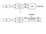
- FIG. 4 is a diagram showing an example of an overview of calibration.
- the same value is converted into different values A and B by being processed in different passes (pass A and pass B).
- the correction coefficient is calculated by comparing different values A and B.
- the value B is converted to the value A by performing correction processing using the correction coefficient on the value B in the latter stage of the pass B.
- the values that have passed through different paths A and B are aligned to the same value A.
- the correction process does not have to be performed after the pass B.
- the correction process may be performed after pass A.
- the correction process may be performed before pass A or before pass B.
- the correction process can be performed before or after at least one of pass A and pass B.
- the correction process may be performed during at least one of pass A and pass B, that is, as the process of at least one of pass A and pass B.
- the calculated correction coefficient may contain an error. Therefore, even if correction is performed using the correction coefficient, there is a possibility that an error is included in the value after correction.
- FIG. 5 is a diagram illustrating an example of information processing according to an embodiment of the present disclosure.
- a background image 510 is displayed on the display device 200 .
- the light source 400B and the subject 600 arranged in the imaging environment, and the background image 510 displayed on the display device 200 are each imaged by the imaging device 300B to generate a captured image.
- the background pass includes processing for displaying the background image 510 on the display device 200 and processing for capturing the background image 510 displayed on the display device 200 by the imaging device 300B.
- the foreground pass includes processing in which the subject 600 is imaged by the imaging device 300B under the light source 400B. Note that the background pass may include processing for generating the background image 510 .
- the captured image captured by the imaging device 300B includes values processed in each of the background pass and the foreground pass. Therefore, even if the values before being processed in the background pass and the foreground pass are the same value (here, for example, the same color or the same object), the value (for example, pixel value) will be a different value for each pass.
- the information processing system 10 performs calibration by comparing outputs of the background pass and the foreground pass.
- the following description assumes that the information processing apparatus 100 of the information processing system 10 performs calibration, more specifically, calculation of correction coefficients. , is not limited to the information processing apparatus 100 .
- the calibration may be performed using an information processing function installed in the display device 200 or an information processing function installed in the imaging device 300B.
- an external device (not shown) may perform the calibration.
- calibration may be performed on multiple devices. In this case, the display device 200, the imaging device 300B, and an external device that performs calibration function as an information processing device.
- the information processing apparatus 100 acquires a first image obtained when a display image displayed on the display device 200 is captured by the imaging device 300B. In addition, the information processing apparatus 100 acquires a second image obtained when the imaging device 300B captures an image in the imaging environment (imaging environment).
- the information processing device 100 Based on the first image and the second image, the information processing device 100 captures the background image 510 displayed on the display device 200 arranged in the imaging environment with the imaging device 300B. is calculated on the display device 200 .
- the information processing system 10 is calibrated.
- the information processing system 10 when the same color is input, the information processing system 10 according to the present embodiment can obtain a color (for example, pixel value) processed in the background pass and a color (for example, pixel value) processed in the foreground pass. For example, the difference in pixel values) can be further reduced. Therefore, the information processing system 10 can acquire a more realistic captured image.
- FIG. 6 is a diagram for explaining an example of correction coefficient calculation processing according to the embodiment of the present disclosure.
- the information processing system 10 generates a first image 561 and a second image 562 .
- the first image 561 and the second image 562 can be generated using a real machine.
- the information processing apparatus 100 acquires the generated first image 561 and second image 562 and calculates correction coefficients.
- a chart image 550 including at least one sample color is displayed on the display device 200.
- a chart image displayed on the display device 200 (hereinafter, also referred to as a chart display image 551) is captured by the imaging device 300B, whereby a first image 561 is generated.
- a first image 561 is input to the information processing apparatus 100 .
- a second image 562 is generated by imaging the color chart 620 with the imaging device 300B under the light source 400B arranged in the imaging environment.
- a second image 562 is input to the information processing apparatus 100 .
- the chart image 550 and the color chart 620 contain the same sample colors.
- the chart image 550 is an RGB image of the color chart 620 captured.
- the color chart 620 may be imaged in an environment different from the imaging environment, and the chart image 550 may be generated.
- the chart image 550 may be an RGB image generated based on the spectral reflectance data of the color chart 620.
- the imaging environment is an environment in which imaging is actually performed after calibration (hereinafter also referred to as an actual imaging environment). ) does not have to be the same as
- the spectral characteristics of the light source 400B, the characteristics of the imaging device 300B, and the settings of the display device 200 may be the same as those of the light source, imaging device, and display device arranged in the actual imaging environment. , location, etc. may be different.
- the information processing device 100 can acquire the first image 561 and the second image 562 directly from the imaging device 300B. Alternatively, the information processing device 100 can acquire the first image 561 and the second image 562 as image files from the imaging device 300B. In this case, the information processing device 100 may acquire the image file through direct communication with the imaging device 300B, or may acquire the image file via a removable storage medium such as a USB memory or SD card.
- a removable storage medium such as a USB memory or SD card.
- the information processing apparatus 100 calculates correction coefficients based on the acquired first image 561 and second image 562 . For example, the information processing apparatus 100 compares the pixel values of the same color included in each of the first image 561 and the second image 562, and calculates a correction coefficient so that the difference between the pixel values becomes smaller. For example, the information processing apparatus 100 calculates correction coefficients using existing techniques such as the least squares method.
- the information processing apparatus 100 calculates the correction coefficient using the second image 562 as a reference. That is, the information processing apparatus 100 calculates a correction coefficient for correcting the background path.
- the information processing apparatus 100 may calculate the correction coefficient using the first image 561 as a reference. That is, the information processing apparatus 100 may calculate a correction coefficient for correcting the foreground pass.
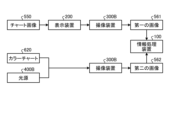
- FIG. 7 is a diagram for explaining another example of the correction coefficient calculation process according to the embodiment of the present disclosure.
- the information processing apparatus 100 generates a first image 561 and a second image 562 .
- the first image 561 and the second image 562 may be calculated on the desk.
- the information processing apparatus 100 generates a first image 561 and a second image 562 and calculates correction coefficients based on the generated first image 561 and second image 562 .
- the information processing apparatus 100 generates the chart image 550 by performing the first image conversion using the spectral reflectance data.
- the information processing apparatus 100 performs the first image conversion using the spectral reflectance data of the color chart 620 shown in FIG. 6 to generate the chart image 550 .
- the information processing device 100 generates a chart display image 551 by performing a second image transformation on the chart image 550 based on the display characteristics of the display device 200 .
- the display characteristics are, for example, characteristics when an RGB image is input to the display device 200 and output by the display device 200 as light. Display characteristics include, for example, white balance.
- This chart display image 551 is generated by simulation of an image obtained when the chart image 550 is displayed on the display device 200 .
- the information processing device 100 generates a first image 561 by performing third image conversion on the chart display image 551 based on the imaging characteristics of the imaging device 300B.
- the imaging characteristics are, for example, characteristics related to RGB images output by the imaging device 300B when light is input to the imaging device 300B.
- the imaging characteristics include, for example, spectral sensitivity characteristics of the imaging device 300B, white balance, and the like.
- This first image 561 is generated by simulation of an image obtained when the chart display image 551 is captured by the imaging device 300B.
- the information processing apparatus 100 performs the first to third image conversions to generate the first image 561, but the information processing apparatus 100 generates the first image 561 by one image conversion. may be generated.
- the first to third image transformations are combined into one image transformation, and the information processing apparatus 100 performs the image transformation on the spectral reflectance data to generate the first image 561.
- the information processing apparatus 100 performs the image transformation on the spectral reflectance data to generate the first image 561.
- the number of image conversions performed by the information processing apparatus 100 to generate the first image 561 is not limited to three, and may be two or less or four or more.
- the information processing apparatus 100 performs fourth image conversion using the spectral reflectance data, the light source spectral data, and the imaging characteristics of the imaging device 300B to generate a second image 562.
- the information processing apparatus 100 performs the fourth image conversion by generating an image obtained by multiplying the spectral reflectance data and the light source spectral data as the second image 562 when the imaging apparatus 300B captures the product.
- the spectral reflectance data used by the information processing apparatus 100 in the fourth image conversion is the same as the spectral reflectance data used to generate the first image 561 .
- the light source spectral data is the same as the spectral characteristic data of the light source 400B arranged in the actual imaging environment.
- the light source spectral data may be calculated in advance from the type of the light source 400B or the like, or the spectral data of the light source 400B may be measured using a spectrometer or the like.
- the information processing device 100 that has generated the first image 561 and the second image 562 compares these images and calculates correction coefficients.
- the calculation method is the same as in the case of FIG.
- the method of generating the first image 561 and the second image 562 using an actual device and a method of generating the first image 561 and the second image 562 on a desk have been described.
- the method of generating the first image 561 and the second image 562 is not limited to this.
- the first image 561 is generated on the desk (for example, by the information processing apparatus 100), and the second image 562 is generated on the actual machine. may be performed.
- the information processing system 10 performs calibration by applying the correction coefficient calculated by the information processing apparatus 100 to at least one of the background pass and the foreground pass. An example of a method of applying correction coefficients by the information processing system 10 will be described below. In the following description, the information processing apparatus 100 applies the correction coefficient unless otherwise specified.
- FIG. 8 is a diagram for explaining a first application example of correction coefficients according to the embodiment of the present disclosure.
- FIG. 8 shows a case where the information processing device 100 applies the correction coefficients to the background image 510 .
- the information processing device 100 applies the correction coefficients to the background image 510 to generate a corrected background image.
- the information processing device 100 inputs the generated corrected background image to the display device 200 .
- the display device 200 displays the corrected background image.
- the imaging device 300B captures the corrected background image and the subject 600 displayed on the display device 200, and generates a corrected captured image.
- the information processing apparatus 100 reduces the difference between the color when the corrected background image is re-captured and the color of the subject 600. It is assumed that the correction coefficient for
- the information processing device 100 calculates a correction coefficient that adds the influence of the light source 400B and cancels the influence of the display device 200.
- the information processing apparatus 100 can further reduce the color difference between the first image 561 and the second image 562 .
- the imaging device 300B can capture an image with higher reality.
- FIG. 9 is a diagram for explaining a second application example of the correction coefficients according to the embodiment of the present disclosure.
- FIG. 9 shows a case where the information processing device 100 applies the correction coefficients to the display device 200 .
- the information processing device 100 applies the correction coefficients to the display device 200 by inputting the correction coefficients to the display device 200 .
- the display device 200 performs processing (for example, correction processing) according to the correction coefficient on the background image 510 and displays it.
- processing for example, correction processing
- an image displayed by the display device 200 applying the correction coefficients is also referred to as a corrected display image.
- the imaging device 300B captures the corrected display background image and the subject 600, and generates a corrected captured image.
- the information processing apparatus 100 reduces the difference between the color when the corrected background image is re-captured and the color of the subject 600. It is assumed that the correction coefficient for
- the information processing device 100 calculates a correction coefficient that adds the influence of the light source 400B and cancels the influence of the display device 200.
- the information processing apparatus 100 can further reduce the color difference between the first image 561 and the second image 562 .
- the imaging device 300B can capture an image with higher reality.
- FIG. 10 is a diagram for explaining a third application example of correction coefficients according to the embodiment of the present disclosure.
- FIG. 10 shows a case where the information processing device 100 applies the correction coefficient to the light source 400B.
- the information processing device 100 applies the correction coefficient to the light source 400B by inputting the correction coefficient to the light source 400B.
- the light source 400B corrects the characteristics according to the correction coefficient. For example, the light source 400B corrects the characteristics by changing the color of the emitted light according to the correction coefficient, and emits corrected light source light.
- the information processing device 100 calculates a correction coefficient that cancels the influence of the light source 400B and adds the influence of the display device 200.
- the information processing device 100 can reduce the influence of the light source 400B and the influence of the display device 200 by applying this correction coefficient to the light source 400B.
- the imaging device 300B can capture an image with higher reality.
- the correction that the light source 400B can perform is limited in its contents. Therefore, the light source 400B performs correction that can reduce the influence of the light source 400B and the influence of the display device 200, for example, based on the correction coefficient.
- the correction coefficient includes the influence of the display device 200 and the influence of the light source 400B. Therefore, the information processing device 100 separates the correction coefficients into a first correction coefficient including the influence of the display device 200 and a second correction coefficient including the influence of the light source 400B, and assigns the first correction coefficient to each pass. A factor and a second correction factor may be applied.
- the information processing device 100 calculates a first correction coefficient that cancels the influence of the display device 200 and applies it to the background path. Also, for example, the information processing apparatus 100 calculates a second correction coefficient that cancels the influence of the light source 400B, and applies it to the foreground pass.
- the information processing device 100 calculates a first correction coefficient that adds the influence of the display device 200 and applies it to the foreground pass. Also, for example, the information processing apparatus 100 calculates a second correction coefficient that adds the influence of the light source 400B, and applies it to the background path.
- the information processing apparatus 100 separates the correction coefficient into the first correction coefficient and the second correction coefficient and applies them to the information processing system 10, thereby reducing the influence of the display device 200 and the influence of the light source 400B. Can be distributed and reduced.
- the information processing device 100 can change the balance between the influence of the display device 200 and the influence of the light source 400B included in the first correction coefficient and the second correction coefficient. Accordingly, the information processing apparatus 100 can adjust the calibration reference to the foreground pass reference, the background pass reference, or the intermediate reference between the foreground pass and the background pass.
- Second calibration example> Next, a second calibration example will be described.
- the information processing apparatus 100 calculates the first correction coefficient and the second correction coefficient for each of the first image 561 and the second image 562 described above.
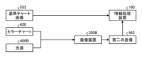
- FIG. 11 is a diagram for explaining an example of calculation processing of the first correction coefficient according to the embodiment of the present disclosure.
- the information processing system 10 generates a first image 561 . That is, here, it is assumed that the first image 561 is generated using the actual machine.
- the first image 561 may be generated on the desk (for example, inside the information processing apparatus 100). Since the method of generating the first image 561 on the actual device and the method of generating it on the desk are the same as the methods shown in FIGS. 6 and 7, description thereof is omitted.
- the information processing apparatus 100 compares the chart image 550 (an example of the display image) and the first image 561 to calculate a first correction coefficient (an example of the first coefficient).
- the first correction coefficient includes the influence of the display device 200 and the influence of the imaging device 300B (the influence of the spectral characteristics of the imaging device 300B on the spectral characteristics of the display device 200).
- the information processing apparatus 100 calculates the first correction coefficient based on the chart image 550 and the first image 561.
- FIG. 12 is a diagram for explaining an example of the second correction coefficient calculation process according to the embodiment of the present disclosure.
- the information processing system 10 generates a second image 562 . That is, here, it is assumed that the second image 562 is generated using the actual machine.
- the second image 562 may be generated on the desk (for example, inside the information processing apparatus 100). Since the method of generating the second image 562 on the actual device and the method of generating it on the desk are the same as the methods shown in FIGS. 6 and 7, description thereof will be omitted.
- the information processing apparatus 100 compares the reference chart image 553 (an example of the reference image) and the second image 562 to calculate a second correction coefficient (an example of the second coefficient).
- This second correction factor includes the effect of light source 400B.
- the information processing apparatus 100 calculates the second correction coefficient based on the reference chart image 552 and the second image 562.
- the reference chart image 553 is an image obtained when the color chart 620 is imaged under a reference light source, for example.
- the reference light source may be, for example, the light source 400A (see FIG. 1) of the environment in which the background image 510 is captured, or a standard light source such as the D65 light source.
- the information processing apparatus 100 calculates one correction coefficient from the calculated first correction coefficient and second correction coefficient.
- the information processing apparatus 100 can perform calibration by applying the calculated correction coefficient to at least one of the background pass and the foreground pass.
- An example in which the correction coefficient is applied to one of the background pass and the foreground pass is the same as the examples in FIGS. 8 to 10, so description thereof will be omitted.
- the information processing apparatus 100 may perform calibration by applying the calculated first correction coefficient and second correction coefficient to the background pass and the foreground pass, respectively.
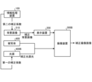
- FIG. 13 is a diagram for explaining application examples of the first and second correction coefficients according to the embodiment of the present disclosure.
- the first correction coefficient includes the influence of the display device 200. Also, the second correction coefficient includes the influence of the light source 400B.
- the information processing device 100 calculates, for example, a first correction coefficient that adds the influence of the display device 200, the first correction coefficient is applied to the light source 400B.
- the information processing device 100 can apply the first correction coefficient to the light source 400B in the same manner as the method of FIG.
- the information processing apparatus 100 calculates a second correction coefficient that adds the influence of the light source 400B
- the information processing apparatus 100 applies this second correction coefficient to the background image 510.
- the information processing apparatus 100 can apply the second correction coefficient to the background image 510 in the same manner as the method shown in FIG.
- the information processing device 100 may apply to the display device 200 a second correction coefficient that adds the influence of the light source 400B.
- the information processing device 100 can apply the second correction coefficient to the display device 200 in the same manner as the method shown in FIG. 9 .
- the information processing apparatus 100 applies the first correction coefficient to the background pass and the second correction coefficient to the foreground pass.
- a correction factor of two may be applied to the background pass.
- the information processing device 100 calculates a first correction coefficient that cancels the influence of the display device 200 and applies it to at least one of the background image 510 and the display device 200 .
- the information processing apparatus 100 also calculates a second correction coefficient that cancels the influence of the light source 400B and applies it to the light source 400B.
- the information processing apparatus 100 can calibrate the information processing system 10 by calculating the first correction coefficient and the second correction coefficient in the foreground pass and the background pass, respectively. Thereby, the imaging device 300B can capture an image with higher reality.
- the information processing apparatus 100 can present information about calibration (hereinafter also referred to as calibration information) to a user (for example, a person who takes an image using the imaging device 300B).
- the information processing apparatus 100 can present the information to the user by displaying the calibration information on its own display unit (not shown).
- the information processing device 100 may display the calibration information on the display device 200 of the information processing system 10, using a display function of the information processing system 10 such as a display unit (not shown) of the imaging device 300B. may display calibration information.
- the information processing apparatus 100 transfers the calibration information to an external terminal (not shown), which is an external device such as a smartphone or a tablet PC, using wired communication or wireless communication. Calibration information may be displayed.
- the information processing apparatus 100 can present images before and after calibration to the user as calibration information.
- the information processing apparatus 100 presents the captured image before applying the correction coefficients and the corrected captured image after applying the correction coefficients to the user.
- the information processing apparatus 100 may present the captured image and the corrected captured image side by side to the user, or may present them individually.
- the information processing apparatus 100 may present the user with, for example, the first image 561 and the second image 562 as the calibration information.
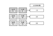
- FIG. 14 is a diagram showing an example of calibration information presented by the information processing device 100 according to the embodiment of the present disclosure.
- the information processing apparatus 100 displays the first image 561 and the second image 562 side by side for each sample color included in the images. For example, the information processing apparatus 100 may select the sample colors included in the second image 562 (foreground colors #1 to #3 in FIG. 14) and the sample colors included in the first image 561 (background color # in FIG. 14). 1 to #3) are displayed side by side for each sample color.
- the foreground color and background color with the same number are colors obtained by processing sample colors with the same spectral reflectance in the foreground pass and background pass, respectively.
- the information processing apparatus 100 presents the first image 561 and the second image 562 to the user for each sample color, so that the user can confirm the color difference for each sample color.
- the information processing apparatus 100 in addition to (or in place of) the first image 561 and the second image 562, provides information about the color difference between the first image 561 and the second image 562. (an example of color difference information) may be presented to the user.
- the information processing apparatus 100 presents to the user, for each sample color, color difference values calculated using a color difference calculation method such as ⁇ E2000 as color difference information.
- the information processing apparatus 100 presents the information about the color difference to the user, so that the user can confirm the color difference between the first image 561 and the second image 562 based on the information about the color difference.
- FIG. 15 is a diagram showing another example of calibration information presented by the information processing apparatus 100 according to the embodiment of the present disclosure.
- the information processing apparatus 100 indicates the color difference between the first image 561 and the second image 562 on the xy chromaticity diagram.
- the information processing apparatus 100 maps the sample colors included in the first image 561 and the second image 562 on an xy chromaticity diagram and presents them to the user.
- the information processing apparatus 100 maps the sample colors of the first image 561 to positions indicated by circles and the sample colors of the second image 562 to positions indicated by squares.
- the information processing apparatus 100 can present the color difference of the sample colors included in the first image 561 and the second image 562 as Euclidean distances on the xy chromaticity diagram.
- the information processing apparatus 100 presents the calibration information to the user using the xy chromaticity diagram, so that the user can more easily check the color difference between the first image 561 and the second image 562. can be done.
- FIG. 16 is a diagram showing another example of calibration information presented by the information processing device 100 according to the embodiment of the present disclosure.
- the number of sample colors included in the first image 561 and the second image 562 may be many, such as thousands. In this way, when the first image 561 and the second image 562 contain a large number of sample colors, the information processing apparatus 100 calculates the average value, median value, standard At least one of values such as deviation and worst case may be calculated.
- the information processing apparatus 100 shows the distribution information of the calculated standard deviation on the xy chromaticity diagram. In this way, the information processing apparatus 100 can present the color difference statistical information to the user as calibration information.
- the information processing apparatus 100 presents the color difference statistical information to the user, so that the user can statistically confirm the color difference between the first image 561 and the second image 562 .
- the color difference between the first image 561 and the second image 562 is shown on the xy chromaticity diagram as an example. can be expressed as
- the information processing apparatus 100 presents the comparison result of the first image 561 and the second image 562 to the user as calibration information, but the information presented by the information processing apparatus 100 is , but not limited to.
- the information processing apparatus 100 compares the first image 561 with a corrected second image obtained by applying a correction coefficient to the foreground path (hereinafter also referred to as a corrected second image).
- the results may be presented to the user as calibration information.
- the corrected second image is an image obtained when a correction coefficient is applied to the light source 400B and the color chart is captured by the imaging device 300B.
- the information processing apparatus 100 compares the corrected first image obtained by applying the correction coefficient to the background path (hereinafter also referred to as the corrected first image) and the second image 562.
- the results may be presented to the user as calibration information.
- the corrected first image is an image obtained when a correction coefficient is applied to the chart image 550 or the display device 200 and the corrected chart image displayed on the display device 200 is captured by the imaging device 300B.
- Information used by information processing apparatus 100 to generate simulation information may be information generated on a desk, or may be generated using an actual machine. It may be information obtained by
- the information processing device 100 may generate the first image 561 by itself or acquire it from the imaging device 300B.
- the information processing apparatus 100 may generate the correction first image by itself or acquire it from the imaging device 300B. The same is true for the second image 562 and the corrected second image.
- the information processing apparatus 100 can acquire the second image 562 of the color chart captured by the imaging device 300B. For example, the information processing apparatus 100 compares the sample colors included in the second image 562 with the sample colors included in the first image 561 to calculate correction coefficients. At this time, the information processing apparatus 100 may automatically recognize the color chart using the color chart information, for example.
- FIG. 17 is a diagram showing an example of a color chart according to the embodiment of the present disclosure.
- the color chart includes at least one (four in the example of FIG. 17) markers 710 as color chart information.
- the information processing apparatus 100 detects the shape of the color chart and the positions of the sample colors (color charts), for example, by detecting the markers 710 included in the second image 562 .
- the shape, color, and number of markers 710 shown in FIG. 17 are examples, and are not limited to the example in FIG.
- the marker 710 may have any shape as long as it can be detected by the information processing apparatus 100 . It is assumed that the information processing apparatus 100 has acquired information regarding the marker 710 in advance. Alternatively, the information processing apparatus 100 may acquire information about the shape of the color chart in advance as color chart information, and detect the shape of the color chart from the second image 562 .
- the information processing apparatus 100 that recognizes the color chart detects the color value of the sample color by calculating the average value of the central area of the sample color (for example, area 720 in FIG. 17).
- the information processing apparatus 100 can, for example, calculate the average value of the central region for all sample colors included in the color chart.
- the information processing apparatus 100 detects the average value of the predetermined area as the sample color, so that errors due to imaging can be reduced, and correction coefficients can be calculated more accurately.
- the color chart may include sample color information regarding sample colors in addition to the markers 710 .
- the color chart has a two-dimensional barcode 730 containing sample color information.
- the sample color information indicated by the two-dimensional barcode includes, for example, the spectral reflectance of the sample color.
- the information processing device 100 acquires sample color information by reading the two-dimensional barcode. For example, the information processing apparatus 100 uses the sample color information to calculate the correction coefficient.
- the information processing apparatus 100 acquires sample colors and sample color information from the second image 562 using the markers 710 and the like, the information processing apparatus 100 acquires the sample colors from the first image 561 in the same manner. or sample color information.
- the chart image 550 includes markers 710 and sample color information (eg, two-dimensional barcode).
- sample color information may be information other than the two-dimensional barcode.
- sample color information may be information displayed by character strings or numbers.
- FIG. 18 is a block diagram showing a configuration example of the information processing device 100 according to the embodiment of the present disclosure.
- the information processing device 100 includes a communication section 110 , a storage section 120 , a control section 130 and a display section 140 .
- the communication unit 110 is a communication interface that communicates with an external device via a network by wire or wirelessly.
- the communication unit 110 is realized by, for example, a NIC (Network Interface Card) or the like.
- the storage unit 120 is a data readable/writable storage device such as a DRAM, an SRAM, a flash memory, or a hard disk.
- the storage unit 120 functions as storage means of the information processing apparatus 100 .
- the display unit 140 is, for example, a panel-type display device such as a liquid crystal panel or an organic EL (Electro Luminescence) panel, and displays the calibration information described above, for example, under the control of the control unit 130 .
- the display unit 140 functions as display means of the information processing device 100 .
- the control unit 130 controls each unit of the information processing device 100 .
- the control unit 130 stores a program stored inside the information processing apparatus 100 by a CPU (Central Processing Unit), an MPU (Micro Processing Unit), a GPU (Graphics Processing Unit), or the like in a RAM (Random Access Memory) or the like as a work area. It is realized by executing as Also, the control unit 130 is implemented by an integrated circuit such as an ASIC (Application Specific Integrated Circuit) or an FPGA (Field Programmable Gate Array).
- ASIC Application Specific Integrated Circuit
- FPGA Field Programmable Gate Array
- the control unit 130 includes a first image acquisition unit 131 , a second image acquisition unit 132 , a coefficient calculation unit 133 , a correction processing unit 134 and a display control unit 135 .
- Each block (the first image acquisition unit 131 to the display control unit 135) constituting the control unit 130 is a functional block indicating the function of the control unit 130.
- FIG. These functional blocks may be software blocks or hardware blocks.
- each of the functional blocks described above may be one software module realized by software (including microprograms), or may be one circuit block on a semiconductor chip (die). Of course, each functional block may be one processor or one integrated circuit.
- the control unit 130 may be configured in functional units different from the functional blocks described above. The configuration method of the functional blocks is arbitrary.
- control unit 130 may be configured in functional units different from the functional blocks described above. Also, some or all of the blocks (the first image acquisition unit 131 to the display control unit 135) that make up the control unit 130 may be performed by another device. For example, some or all of the blocks that make up the control unit 130 may be operated by a control device realized by cloud computing.
- the first image acquisition unit 131 acquires a first image 561 obtained when the chart display image 551 (an example of the display image) displayed on the display device 200 is captured by the imaging device 300B.
- the first image acquisition unit 131 acquires the first image 561 captured by the imaging device 300B from the imaging device 300B.
- the first image acquisition unit 131 may acquire the first image 561 by generating the first image 561 from the spectral reflectance data through image conversion processing.
- the first image acquisition section 131 outputs the acquired first image 561 to the coefficient calculation section 133 .
- the second image acquisition unit 132 acquires a second image 562 obtained when the color chart is captured by the imaging device 300B in an imaging environment (for example, under the light source 400B).
- the second image acquisition unit 132 acquires the second image 562 captured by the imaging device 300B from the imaging device 300B.
- the second image acquisition unit 132 may acquire the second image 562 by generating the second image 562 from the spectral reflectance data and the spectral data of the light source 400B through image conversion processing. .
- the second image acquisition unit 132 outputs the acquired second image 562 to the coefficient calculation unit 133 .
- the coefficient calculator 133 calculates correction coefficients based on the first image 561 and the second image 562 .
- the correction coefficient is used to display a corrected display image when the background image 510 displayed on the display device 200 arranged in the imaging environment is captured by the imaging device 300B.
- the correction factor can be used to correct light source 400B.
- the coefficient calculator 133 outputs the calculated correction coefficient to the correction processor 134 .
- the correction processor 134 applies the correction coefficients to at least one of the foreground and background passes of the information processing system 10 .
- the correction processing unit 134 applies the correction coefficients to the background path by performing correction processing on the background image 510 using the correction coefficients and generating a corrected background image.
- the correction processing unit 134 performs correction processing using, for example, matrix calculation or a 1D/3D LUT (Lookup Table).
- the correction processing unit 134 can apply the correction coefficients to the background path by outputting the correction coefficients to the display device 200 .
- the display device 200 displays a corrected display image obtained by correcting the background image 510 with the correction coefficient.
- the correction processing unit 134 can apply the correction coefficients to the foreground pass by outputting the correction coefficients to the light source 400B.
- the light source 400B emits irradiation light corrected according to the correction coefficient.
- Display control unit 1335 The display control unit 135 causes the display unit 140 to display various information. For example, the display control unit 135 generates the calibration information described above and causes the display unit 140 to display it.
- the display control unit 135 causes the display unit 140 included in the information processing apparatus 100 to display the calibration information. good too.
- the display control unit 135 may cause the display device 200 to display the calibration information.
- the display control section 135 outputs calibration information to the display device 200 .
- processing example An example of processing performed by the information processing system 10 according to the embodiment of the present disclosure will be described below.
- calibration processing for performing the above-described calibration and imaging processing for performing imaging to which correction coefficients are applied in an actual imaging environment are performed.
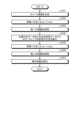
- FIG. 19 is a flowchart showing an example of the flow of calibration processing according to the embodiment of the present disclosure.
- the calibration process shown in FIG. 19 is executed by the information processing apparatus 100.
- the information processing apparatus 100 generates a chart image 550 (step S101).
- the information processing apparatus 100 generates a chart image 550 from spectral reflectance data, for example.
- the information processing apparatus 100 may determine the conversion coefficient from the spectral reflectance data to the chart image 550 according to the color gamut of the production environment of the chart image 550 .
- the information processing apparatus 100 simulates the background path (step S102) and acquires the first image 561 (step S103).
- the information processing apparatus 100 acquires the characteristics of the display device 200, more specifically, the conversion characteristics of the display device 200 that converts an input RGB image into output light by measurement or the like in advance. Further, for example, the information processing apparatus 100 may acquire the characteristics of the display device 200 from the display device 200 using wired communication or wireless communication, or acquire the characteristics of the display device 200 from the outside via the Internet. good too.
- the information processing apparatus 100 acquires in advance the characteristics of the imaging device 300B, more specifically, the conversion characteristics for converting the light input by the imaging device 300B into an RGB image by measurement or the like. Further, for example, the information processing apparatus 100 may acquire the characteristics of the imaging device 300B from the imaging device 300B using wired communication or wireless communication, or acquire the characteristics of the imaging device 300B from the outside via the Internet. good too.
- the information processing device 100 performs a background path simulation using the characteristics of the display device 200 and the characteristics of the imaging device 300B, and acquires the first image 561 .
- the information processing apparatus 100 calculates the spectrum of each color of the color chart from the spectrum data and the spectrum reflectance data of the light source 400B (step S104). It is assumed that the information processing apparatus 100 acquires in advance spectral data of the light source 400B measured by, for example, a spectrometer or the like. Further, for example, the information processing apparatus 100 may acquire the spectral data of the light source 400B from the light source 400B using wired communication or wireless communication, or may acquire the spectral data of the light source 400B from the outside via the Internet. good.
- the information processing apparatus 100 simulates the foreground path (step S105) and acquires the second image 562 (step S106).
- the information processing device 100 performs a foreground pass simulation using the characteristics of the imaging device 300B described above, and acquires a second image 562 .
- the information processing apparatus 100 calculates correction coefficients using the first image 561 and the second image 562 (step S107).
- the information processing apparatus 100 calculates the correction coefficient using, for example, the method of least squares.
- steps S101 to S103 and the processing of steps S104 to S106 may be performed interchangeably, or may be processed in parallel.
- the information processing device 100 generates the first image 561 and the second image 562 by an imaging device. 300B.
- FIG. 20 is a flowchart showing an example of the flow of calibration processing according to the embodiment of the present disclosure.
- the calibration process shown in FIG. 20 is executed by each device of the information processing system 10.
- FIG. That is, the calibration processing shown in FIG. 20 is processing using an actual machine.
- the same reference numerals are given to the same processes as in FIG. 19, and the description thereof is omitted.
- the information processing device 100 of the information processing system 10 generates a chart image 550 from the color chart (step S201).
- the information processing apparatus 100 acquires spectral reflectance data of a color chart, for example, and generates a chart image 550 based on this spectral reflectance data.
- the spectral reflectance data is, for example, data obtained by measuring the spectral reflectance of an actual color chart.
- the information processing apparatus 100 causes the display device 200 to display the chart image 550 by inputting the chart image 550 to the display device 200 (step S202).
- the imaging device 300B of the information processing system 10 images the display device 200 displaying the chart image 550 (step S203).
- the information processing device 100 acquires the first image 561 from the imaging device 300B (step S204).
- the imaging device 300B captures an image of the actual color chart placed in the imaging environment (for example, under the light source 400B) (step S205).
- the information processing device 100 acquires the second image 562 from the imaging device 300B (step S206).
- the information processing apparatus 100 calculates correction coefficients using the first image 561 and the second image 562 (step S207).
- the information processing apparatus 100 calculates the correction coefficient using, for example, the method of least squares.
- steps S201 to S204 and the processing of steps S205 to S206 may be performed interchangeably, or may be processed in parallel.
- the imaging device 300B simultaneously captures the display device 200 on which the chart image 550 is displayed and the actual color chart, thereby generating a third image including the first image 561 and the second image 562.
- the information processing apparatus 100 cuts out an area including the display device 200 from the third image as the first image 561 and cuts out an area including the color chart as the second image 562, thereby obtaining the first image.
- An image 561 and a second image 562 may be acquired.
- FIG. 21 is a flowchart illustrating an example of the flow of imaging processing according to the embodiment of the present disclosure.
- the imaging process illustrated in FIG. 21 is executed by each device of the information processing system 10, for example.
- the information processing device 100 may apply the correction coefficient to at least one of the display device 200 and the light source 400B.
- the information processing apparatus 100 corrects the background image 510 with the correction coefficients calculated by the calibration process (step S301).
- the information processing device 100 causes the display device 200 to display the corrected background image 510 (corrected background image) (step S302).
- the imaging device 300B images the subject 600 and the display device 200 (step S303).
- the information processing system 10 can acquire a corrected captured image, and can acquire an image with a higher degree of reality.
- FIG. 22 is a hardware configuration diagram showing an example of a computer 1000 that implements the functions of the information processing apparatus 100.
- the computer 1000 has a CPU 1100 , a RAM 1200 , a ROM (Read Only Memory) 1300 , a HDD (Hard Disk Drive) 1400 , a communication interface 1500 and an input/output interface 1600 .
- Each part of computer 1000 is connected by bus 1050 .
- the CPU 1100 operates based on programs stored in the ROM 1300 or HDD 1400 and controls each section. For example, the CPU 1100 loads programs stored in the ROM 1300 or HDD 1400 into the RAM 1200 and executes processes corresponding to various programs.
- the ROM 1300 stores a boot program such as BIOS (Basic Input Output System) executed by the CPU 1100 when the computer 1000 is started, and programs dependent on the hardware of the computer 1000.
- BIOS Basic Input Output System
- the HDD 1400 is a computer-readable recording medium that non-temporarily records programs executed by the CPU 1100 and data used by such programs.
- the HDD 1400 is a recording medium that records the audio reproduction program according to the present disclosure, which is an example of the program data 1450 .
- a communication interface 1500 is an interface for connecting the computer 1000 to an external network 1550 (for example, the Internet).
- CPU 1100 receives data from another device via communication interface 1500, and transmits data generated by CPU 1100 to another device.
- the input/output interface 1600 is an interface for connecting the input/output device 1650 and the computer 1000 .
- the CPU 1100 receives data from input devices such as a keyboard and mouse via the input/output interface 1600 .
- the CPU 1100 also transmits data to an output device such as a display, speaker, or printer via the input/output interface 1600 .
- the input/output interface 1600 may function as a media interface for reading a program or the like recorded on a predetermined recording medium.
- Media include, for example, optical recording media such as DVD (Digital Versatile Disc) and PD (Phase change rewritable disk), magneto-optical recording media such as MO (Magneto-Optical disk), tape media, magnetic recording media, semiconductor memories, etc. is.
- the CPU 1100 of the computer 1000 implements the functions of the control unit 130 and the like by executing the information processing program loaded on the RAM 1200.
- the HDD 1400 also stores an information processing program according to the present disclosure and data in the storage unit 120 .
- CPU 1100 reads and executes program data 1450 from HDD 1400 , as another example, these programs may be obtained from another device via external network 1550 .
- control device that controls the information processing device 100 of this embodiment may be implemented by a dedicated computer system or by a general-purpose computer system.
- a communication program for executing the above operations is distributed by storing it in a computer-readable recording medium such as an optical disk, semiconductor memory, magnetic tape, or flexible disk.
- the control device is configured by installing the program in a computer and executing the above-described processing.
- the control device may be a device (for example, a personal computer) external to the information processing device 100 .
- the control device may be a device inside the information processing device 100 (for example, the control unit 130).
- the above communication program may be stored in a disk device provided in a server device on a network such as the Internet, so that it can be downloaded to a computer.
- the functions described above may be realized through cooperation between an OS (Operating System) and application software.
- the parts other than the OS may be stored in a medium and distributed, or the parts other than the OS may be stored in a server device so that they can be downloaded to a computer.
- each component of each device illustrated is functionally conceptual and does not necessarily need to be physically configured as illustrated.
- the specific form of distribution and integration of each device is not limited to the illustrated one, and all or part of them can be functionally or physically distributed and integrated in arbitrary units according to various loads and usage conditions. Can be integrated and configured. Note that this distribution/integration configuration may be performed dynamically.
- the present embodiment can be applied to any configuration that constitutes a device or system, such as a processor as a system LSI (Large Scale Integration), a module using a plurality of processors, a unit using a plurality of modules, etc. Furthermore, it can also be implemented as a set or the like (that is, a configuration of a part of the device) to which other functions are added.
- a processor as a system LSI (Large Scale Integration)
- module using a plurality of processors a unit using a plurality of modules, etc.
- it can also be implemented as a set or the like (that is, a configuration of a part of the device) to which other functions are added.
- the system means a set of a plurality of components (devices, modules (parts), etc.), and it does not matter whether all the components are in the same housing. Therefore, a plurality of devices housed in separate housings and connected via a network, and a single device housing a plurality of modules in one housing, are both systems. .
- this embodiment can take a configuration of cloud computing in which one function is shared by a plurality of devices via a network and processed jointly.
- the present technology can also take the following configuration. (1) Based on a first image obtained when a display image displayed on a display device is captured by an imaging device, and a second image obtained when the imaging device captures an image in the imaging environment. calculating a correction coefficient used for displaying the corrected image to be re-captured on the display device when the image to be re-captured to be displayed on the arranged display device is captured by the imaging device; control unit, Information processing device. (2) The control unit controls a color obtained by correcting one of the first image and the second image with the correction coefficient, and the color of the other of the first image and the second image.
- the information processing apparatus according to (1), wherein the correction coefficient that reduces the difference between .
- the information processing apparatus wherein the first image is a captured image obtained by capturing, with the imaging device, the display image displayed on the display device arranged in the imaging environment.
- the control unit generates the first image according to spectral characteristics of the display device and characteristics of the imaging device.
- the information processing device (4), wherein the control unit acquires the spectral characteristics of the display device from the display device.
- the information processing device (4) or (5), wherein the control unit acquires the characteristics of the imaging device from the imaging device.
- the information processing device any one of (1) to (6), wherein the second image is a captured image captured by the imaging device in the imaging environment.
- the control unit generates the second image according to spectral characteristics of a light source in the imaging environment and characteristics of the imaging device. processing equipment.
- the correction coefficient includes a first coefficient and a second coefficient, The first coefficient is calculated based on the display image and the first image, The second coefficient according to any one of (1) to (10), wherein the second coefficient is calculated based on a reference image including an object included in the second image and the second image. Information processing equipment.
- the first coefficient is used to correct the recaptured image;
- the information processing device according to (11), wherein the second coefficient is used to correct a light source arranged in the imaging environment.
- the control unit displays at least one of the first image and the second image on a second display device. .
- the control unit converts at least one of a corrected captured image captured by the imaging device by applying the correction coefficient and a captured image captured by the imaging device without applying the correction coefficient to a second
- control unit detects sample colors based on color chart information included in at least one of the first image and the second image. information processing equipment.
- control unit detects sample color information included in at least one of the first image and the second image.
- a program that makes a computer do something. an information processing device; a display device arranged in an imaging environment; an imaging device that captures the imaging environment including the display device, The information processing device is Based on a first image obtained when a display image displayed on the display device is captured by the imaging device and a second image obtained when the imaging device captures the display image in the imaging environment When an image to be re-captured to be displayed on the display device arranged in an imaging environment is captured by the imaging device, a correction coefficient used to display the corrected image to be re-captured on the display device.
- calculating, control unit, An information processing system comprising
Abstract
An information processing device (100) according to the present disclosure comprises a control unit (130). The control unit (130) calculates a correction factor on the basis of a first image obtained when an image-capture device (300B) captures an image of a display image displayed on a display device (200), and a second image obtained when the image-capture device (300B) captures an image in an image-capture environment. When an image of an image for recapturing that is displayed on the display device (200), which is disposed in the image-capture environment, is captured using the image-capture device (300B), the correction factor is used in order to display, on the display device (200), the post-correction image for recapturing.
Description
本開示は、情報処理装置、プログラム及び情報処理システムに関する。
The present disclosure relates to an information processing device, a program, and an information processing system.
従来、映画の撮影等において、コンピュータグラフィックス(CG)等の画像を投影した壁面の前で演者が演技を行い、壁面と演者とを同時に撮影することで、CG画像と演者とをリアルタイムに合成して撮影する撮影システムが知られている。
Conventionally, when filming a movie, an actor performs in front of a wall on which images such as computer graphics (CG) are projected. 2. Description of the Related Art There is known a photographing system for photographing by
上述したように、画面(例えば壁面)に映した画像と、物体(例えば演者)と、を同じカメラで撮影する場合、画像を再度撮影した画像(以下、再撮画像とも記載する)のRGB値と物体を撮影した画像(以下、撮像画像とも記載する)のRGB値が異なる場合がある。
As described above, when an image projected on a screen (for example, a wall surface) and an object (for example, a performer) are shot with the same camera, the RGB values of an image that is re-shot (hereinafter also referred to as a re-shot image) and an image obtained by photographing an object (hereinafter, also referred to as a photographed image) may have different RGB values.
具体的には、例えば演者を撮影した画像を壁面に映し、同一人物の演者が壁面の前(実空間)で演技を行って撮影を行うとする。この場合、画像中の演者の再撮画像の色(RGB値)と、壁面の前の実際の演者の撮影画像の色(RGB値)が異なる場合がある。
Specifically, for example, an image of a performer is projected onto a wall, and the same performer acts in front of the wall (in real space) and is filmed. In this case, the colors (RGB values) of the re-captured image of the performer in the image may differ from the colors (RGB values) of the actual captured image of the performer in front of the wall.
これは、実空間の物体の分光特性と、画面に映す画像の分光特性と、が異なるためである。そのため、例えば、画面と実空間の物体とを同時に撮影してもリアリティ(現実感)が高い画像が得られるとは言えなかった。
This is because the spectral characteristics of objects in real space differ from the spectral characteristics of images projected on the screen. Therefore, for example, even if the screen and the object in the real space are photographed at the same time, it cannot be said that a highly realistic image can be obtained.
そのため、再撮画像のRGB値と、実空間の撮影画像のRGB値と、を揃え、よりリアリティの高い画像を撮影することが望まれる。
Therefore, it is desirable to align the RGB values of the re-captured image with the RGB values of the captured image in the real space to capture a more realistic image.
そこで、本開示では、よりリアリティの高い画像を取得することができる仕組みを提供する。
Therefore, the present disclosure provides a mechanism capable of acquiring a more realistic image.
なお、上記課題又は目的は、本明細書に開示される複数の実施形態が解決し得、又は達成し得る複数の課題又は目的の1つに過ぎない。
It should be noted that the above problem or object is only one of the multiple problems or objects that can be solved or achieved by the multiple embodiments disclosed herein.
本開示の情報処理装置は、制御部を備える。制御部は、表示装置に表示される表示画像を撮像装置で撮像した場合に得られる第一の画像、及び、撮像環境において前記撮像装置で撮像した場合に得られる第二の画像、に基づき補正係数を算出する。補正係数は、前記撮像環境に配置される前記表示装置に表示される再撮用画像を前記撮像装置で撮像する場合に、補正後の前記再撮用画像を前記表示装置に表示するために使用される。
The information processing device of the present disclosure includes a control unit. The control unit corrects a display image displayed on a display device based on a first image obtained when an image is captured by an imaging device, and a second image obtained when an image is captured by the imaging device in an imaging environment. Calculate the coefficient. The correction coefficient is used to display the re-captured image after correction on the display device when the imaging device captures the re-captured image to be displayed on the display device arranged in the imaging environment. be done.
以下に添付図面を参照しながら、本開示の実施形態について詳細に説明する。なお、本明細書及び図面において、実質的に同一の機能構成を有する構成要素については、同一の符号を付することにより重複説明を省略する。
Embodiments of the present disclosure will be described in detail below with reference to the accompanying drawings. In the present specification and drawings, constituent elements having substantially the same functional configuration are denoted by the same reference numerals, thereby omitting redundant description.
また、本明細書及び図面において、実質的に同一または類似の機能構成を有する複数の構成要素を、同一の符号の後に異なる数字を付して区別する場合がある。ただし、実質的に同一または類似の機能構成を有する複数の構成要素の各々を特に区別する必要が無い場合、同一符号のみを付する。また、異なる実施形態の類似する構成要素については、同一の符号の後に異なるアルファベット又は数字を付して区別する場合がある。ただし、類似する構成要素の各々を特に区別する必要が無い場合、同一符号のみを付する。
In addition, in this specification and drawings, a plurality of components having substantially the same or similar functional configurations may be distinguished by attaching different numerals after the same reference numerals. However, when there is no particular need to distinguish between a plurality of components having substantially the same or similar functional configurations, only the same reference numerals are used. Further, similar components of different embodiments may be distinguished by attaching different alphabets or numerals after the same reference numerals. However, when there is no particular need to distinguish between similar components, only the same reference numerals are used.
また、本明細書及び図面において、具体的な値を示して説明する場合があるが、値は一例であり、別の値が適用されてもよい。
Also, in this specification and drawings, there are cases where specific values are shown and explained, but the values are examples, and other values may be applied.
以下に説明される1又は複数の実施形態(実施例、変形例を含む)は、各々が独立に実施されることが可能である。一方で、以下に説明される複数の実施形態は少なくとも一部が他の実施形態の少なくとも一部と適宜組み合わせて実施されてもよい。これら複数の実施形態は、互いに異なる新規な特徴を含み得る。したがって、これら複数の実施形態は、互いに異なる目的又は課題を解決することに寄与し得、互いに異なる効果を奏し得る。
Each of one or more embodiments (including examples and modifications) described below can be implemented independently. On the other hand, at least some of the embodiments described below may be implemented in combination with at least some of the other embodiments as appropriate. These multiple embodiments may include novel features that differ from each other. Therefore, these multiple embodiments can contribute to solving different purposes or problems, and can produce different effects.
<<1.情報処理システムの概要構成例>>
図1は、本開示の実施形態に係る情報処理システム10の概要を説明するための図である。情報処理システム10は、情報処理装置100と、表示装置200と、撮像装置300と、光源400と、を備える。 <<1. Outline configuration example of information processing system>>
FIG. 1 is a diagram for explaining an overview of aninformation processing system 10 according to an embodiment of the present disclosure. The information processing system 10 includes an information processing device 100 , a display device 200 , an imaging device 300 and a light source 400 .
図1は、本開示の実施形態に係る情報処理システム10の概要を説明するための図である。情報処理システム10は、情報処理装置100と、表示装置200と、撮像装置300と、光源400と、を備える。 <<1. Outline configuration example of information processing system>>
FIG. 1 is a diagram for explaining an overview of an
表示装置200は、例えば壁一面の大きさを有するLED(Light Emitting Diode)ディスプレイ(LEDwall)であり、スタジオ等の実空間に配置され得る。図1に示すように、本開示の実施形態に係る情報処理システム10では、3次元仮想空間の映像を背景として表示した表示装置200の前で演者600が演技を行い、それを撮像装置300Bが撮影を行う。これにより、情報処理システム10は、あたかも演者600が3次元仮想空間の中で演技を行ったような映像を取得することができる。
The display device 200 is, for example, an LED (Light Emitting Diode) display (LEDwall) having the size of an entire wall, and can be arranged in a real space such as a studio. As shown in FIG. 1, in the information processing system 10 according to the embodiment of the present disclosure, a performer 600 performs in front of a display device 200 that displays an image of a three-dimensional virtual space as a background, and an imaging device 300B captures the performance. take a picture. As a result, the information processing system 10 can acquire an image as if the performer 600 performed in the three-dimensional virtual space.
ここで、本開示の実施形態では、情報処理装置100が表示装置200に表示する背景画像510(再撮用画像の一例)を生成する。図1の例では、情報処理装置100は、3次元仮想空間内において、仮想の光源400Aの元で仮想の撮像装置300Aで撮影した背景画像510を生成する。
Here, in the embodiment of the present disclosure, the information processing device 100 generates the background image 510 (an example of the re-capture image) to be displayed on the display device 200 . In the example of FIG. 1, the information processing apparatus 100 generates a background image 510 captured by the virtual imaging device 300A under the virtual light source 400A in the three-dimensional virtual space.
撮像装置300Aは、例えば3次元仮想空間(例えばCG空間)内の被写体を撮像する装置(例えば仮想カメラ)である。撮像装置300Aは、例えば、RGB値の背景画像510を撮影するRGBカメラである。なお、ここでは、撮像装置300Aが3次元仮想空間内の被写体を撮像する仮想のRGBカメラであるとしたが、これに限定されない。例えば撮像装置300Aは、実空間内の被写体を撮像するRGBカメラであってもよい。例えば、背景画像510は、Photogrammetry技術などを用いて作成された画像であってもよく、風景や人物などを撮像装置300Aで撮像した実画像であってもよい。また、撮像装置300Aが撮影を行う実空間は、表示装置200が配置される実空間、すなわち撮像装置300Bが撮影を行う実空間とは異なる空間であり得る。
The imaging device 300A is, for example, a device (eg, a virtual camera) that captures an image of a subject in a three-dimensional virtual space (eg, CG space). The imaging device 300A is, for example, an RGB camera that captures a background image 510 of RGB values. Although the imaging device 300A is a virtual RGB camera that captures an image of a subject in a three-dimensional virtual space, it is not limited to this. For example, the imaging device 300A may be an RGB camera that images a subject in real space. For example, the background image 510 may be an image created using a photogrammetry technique or the like, or may be an actual image of scenery, a person, or the like captured by the imaging device 300A. Also, the real space in which the image capturing device 300A captures images may be a space different from the real space in which the display device 200 is arranged, that is, the real space in which the image capturing device 300B captures images.
情報処理装置100は、生成した背景画像510を表示装置200の表示用の画像(表示画像)に変換し、表示画像を表示装置200に表示する。
The information processing device 100 converts the generated background image 510 into an image for display on the display device 200 (display image), and displays the display image on the display device 200 .
撮像装置300Bは、表示装置200と同じ実空間に配置される。撮像装置300Bは、表示装置200に表示される表示画像と、演者600と、を同時に撮影することで、撮像画像540を取得する。撮像装置300Bは、例えば、RGB値の撮像画像540を撮影するRGBカメラである。
The imaging device 300B is placed in the same real space as the display device 200. The imaging device 300B acquires the captured image 540 by simultaneously capturing the display image displayed on the display device 200 and the performer 600 . The imaging device 300B is, for example, an RGB camera that captures an RGB value captured image 540 .
なお、図1の例では、撮像装置300Bは、例えばLED等の光源400Bの元、撮像画像540の撮影を行う。撮像装置300Bは、撮像画像540を情報処理装置100に出力する。
Note that in the example of FIG. 1, the imaging device 300B captures the captured image 540 under the light source 400B such as an LED. The imaging device 300B outputs the captured image 540 to the information processing device 100 .
なお、図1では、表示装置200が、壁一面のLEDwallである場合について示しているが、これに限定されない。例えば、複数面のLEDwallで表示装置200を構成してもよい。あるいは、表示装置200が壁面及び天井(又は床面)に背景画像510を表示する装置であってもよい。あるいは、表示装置200が実空間内の人物と同程度の大きさであるなど、所定の大きさの装置であってもよい。すなわち、表示装置200が表示する背景画像510は、風景等の背景の画像に加え、人物等の物体の画像も含み得る。
Although FIG. 1 shows the case where the display device 200 is an LED wall covering the whole wall, it is not limited to this. For example, the display device 200 may be configured with a plurality of LEDwalls. Alternatively, the display device 200 may be a device that displays the background image 510 on the wall and ceiling (or floor). Alternatively, the display device 200 may be a device of a predetermined size, such as the size of a person in the real space. That is, the background image 510 displayed by the display device 200 may include an image of an object such as a person in addition to a background image such as a landscape.
また、ここでは、表示装置200がLEDディスプレイであるとしたが、これに限定されない。例えば表示装置200がLCD(Liquid Crystal Display)や有機EL(Electroluminescence)ディスプレイであってもよい。
Also, although the display device 200 is an LED display here, it is not limited to this. For example, the display device 200 may be an LCD (Liquid Crystal Display) or an organic EL (Electroluminescence) display.
<<2.従来技術の課題>>
ここで、情報処理システム10において、表示装置200に表示した表示画像を撮像装置300Bで撮影した撮影画像と、実空間の物体を撮影した撮影画像の色(RGB値)が異なる場合がある。かかる点について図2及び図3を用いて説明する。なお、以下、表示装置200に表示した表示画像を撮像装置300Bで撮影した撮影画像を、ディスプレイ撮影画像とも称する。また、実空間の物体を撮影した撮影画像を実物体撮影画像とも称する。 <<2. Problems of conventional technology>>
Here, in theinformation processing system 10, the display image displayed on the display device 200 may have different colors (RGB values) from the captured image captured by the imaging device 300B and the captured image of the object in the real space. This point will be described with reference to FIGS. 2 and 3. FIG. In addition, hereinafter, the captured image obtained by capturing the display image displayed on the display device 200 by the imaging device 300B is also referred to as a display captured image. A photographed image obtained by photographing an object in real space is also referred to as a real object photographed image.
ここで、情報処理システム10において、表示装置200に表示した表示画像を撮像装置300Bで撮影した撮影画像と、実空間の物体を撮影した撮影画像の色(RGB値)が異なる場合がある。かかる点について図2及び図3を用いて説明する。なお、以下、表示装置200に表示した表示画像を撮像装置300Bで撮影した撮影画像を、ディスプレイ撮影画像とも称する。また、実空間の物体を撮影した撮影画像を実物体撮影画像とも称する。 <<2. Problems of conventional technology>>
Here, in the
図2は、実物体撮影画像の一例を説明するための図である。図2に示すように、撮像装置300Bが実空間に配置された物体610(図2の例では自動車)を撮像し、実物体撮像画像541を生成する。
FIG. 2 is a diagram for explaining an example of a photographed image of a real object. As shown in FIG. 2, the imaging device 300B captures an image of an object 610 (a car in the example of FIG. 2) arranged in real space, and generates a real object captured image 541. FIG.
ここで、物体610の分光特性は、実空間の光源の分光特性及び物体610の分光反射率によって決まる。図2のグラフに示すように、実空間に配置された物体610の分光特性の分布は、例えば、なだらかな分布となる。
Here, the spectral characteristics of the object 610 are determined by the spectral characteristics of the light source in real space and the spectral reflectance of the object 610 . As shown in the graph of FIG. 2, the distribution of spectral characteristics of an object 610 placed in real space is, for example, a gentle distribution.
図3は、ディスプレイ撮影画像の一例を説明するための図である。図3に示すように、撮像装置300Bが実空間に配置された表示装置200に表示される物体610を撮像し、ディスプレイ撮像画像542を生成する。なお、表示装置200に表示される物体610は、実空間に配置される物体610(図2参照)と同じ物体であるとする。
FIG. 3 is a diagram for explaining an example of a display captured image. As shown in FIG. 3, the imaging device 300B captures an image of an object 610 displayed on the display device 200 arranged in real space, and generates a display captured image 542. FIG. It is assumed that the object 610 displayed on the display device 200 is the same object as the object 610 (see FIG. 2) placed in the real space.
このとき、撮像装置300Bが同じ物体610を撮影したにもかかわらず、実物体撮像画像541のRGB値と、ディスプレイ撮像画像542のRGB値と、が異なる値になる場合がある。
At this time, even though the imaging device 300B has captured the same object 610, the RGB values of the real object captured image 541 and the display captured image 542 may be different values.
これは、実空間に配置された物体610の分光特性と、表示装置200に表示された物体610の分光特性が異なるためである。
This is because the spectral characteristics of the object 610 placed in the real space and the spectral characteristics of the object 610 displayed on the display device 200 are different.
ここで、表示装置200に表示される表示画像は、例えば、撮像装置300Aで撮像された画像である。そのため、表示装置200に表示される物体610の分光特性は、表示装置200の分光特性に応じた特性となる。例えば、図3のグラフに示すように、表示装置200に表示される物体610の分光特性の分布は、R(Red)、G(Green)、B(Blue)の波長付近でピークを有する分布となる。
Here, the display image displayed on the display device 200 is, for example, an image captured by the imaging device 300A. Therefore, the spectral characteristics of object 610 displayed on display device 200 correspond to the spectral characteristics of display device 200 . For example, as shown in the graph of FIG. 3, the distribution of the spectral characteristics of the object 610 displayed on the display device 200 has peaks near the wavelengths of R (Red), G (Green), and B (Blue). Become.
このように、実空間に配置される物体610の分光分布と、表示装置200に表示される物体610の分光分布と、は異なる。そのため、同じ物体610を撮像装置300Bで撮像した場合に、実物体撮像画像541のRGB値と、ディスプレイ撮像画像542のRGB値と、が異なる値になってしまう。
Thus, the spectral distribution of the object 610 placed in the real space and the spectral distribution of the object 610 displayed on the display device 200 are different. Therefore, when the same object 610 is imaged by the imaging device 300B, the RGB values of the real object captured image 541 and the RGB values of the display captured image 542 are different values.
また、例えば、物体610及び表示装置200のXYZ値が同じになるよう表示装置200を調整したとする。この場合、条件等色対にはなるが、実物体撮像画像541及びディスプレイ撮像画像542のRGB値は同じ値にはならない。
Also, for example, assume that the display device 200 is adjusted so that the XYZ values of the object 610 and the display device 200 are the same. In this case, a metameric pair is obtained, but the RGB values of the captured image 541 of the real object and the captured image 542 of the display are not the same.
ここで、条件等色対とは、2つの物体の色を測色計で計測した場合、2つの物体の分光特性が異なっていても、計測結果が同じ色を示す場合があることを意味する。上述したように、実空間内の物体610の分光特性と、表示装置200に表示される物体610の分光特性は異なる。そこで、例えば、表示装置200に表示される物体610のxy色座標を調整することで、実空間にいる人間から見て、実空間内の物体610と、表示装置200に表示される物体610と、の色味を揃えることはできる。
Here, a metameric color pair means that when the colors of two objects are measured with a colorimeter, the measurement result may show the same color even if the spectral characteristics of the two objects are different. . As described above, the spectral characteristics of the object 610 in real space and the spectral characteristics of the object 610 displayed on the display device 200 are different. Therefore, for example, by adjusting the xy color coordinates of the object 610 displayed on the display device 200, the object 610 in the real space and the object 610 displayed on the display device 200 can be seen from a person in the real space. , colors can be arranged.
しかしながら、撮像装置300Bの分光特性は、人間の目の分光特性と異なる。そのため、実空間にいる人間から見て、実空間内の物体610と、表示装置200に表示される物体610と、の色味が同じであっても、撮像装置300Bが撮影した実物体撮像画像541及びディスプレイ撮像画像542の色味が異なってしまう。
However, the spectral characteristics of the imaging device 300B are different from the spectral characteristics of the human eye. Therefore, even if the object 610 in the real space and the object 610 displayed on the display device 200 have the same color as seen from a person in the real space, the captured image of the real object captured by the imaging device 300B is 541 and the display captured image 542 have different colors.
このように、表示装置200に表示した表示画像を撮像装置300Bで再撮影する場合、表示画像を撮影したディスプレイ撮像画像542の色味と、実空間の物体610を撮像した実物体撮像画像541の色味が異なってしまうという問題があった。
In this way, when the display image displayed on the display device 200 is re-captured by the imaging device 300B, the color of the display captured image 542 obtained by capturing the display image and the real object captured image 541 obtained by capturing the object 610 in the real space are different. There was a problem that the color was different.
そのため、表示画像と実空間の物体610とを同時に撮影しても、表示画像の色味と実空間の物体610の色味が異なり、リアリティのある撮影画像が得られない恐れがある。
Therefore, even if the display image and the object 610 in the real space are photographed at the same time, the color of the display image and the object 610 in the real space are different, and there is a risk that a realistic photographed image cannot be obtained.
<<3.キャリブレーションの概要>>
このように、同じ値であっても、異なるパスで処理することで、パスごとに異なる値となる場合がある。上述した例では、同じ物体610であっても撮影する方法(物体610を直接撮像する方法(パス)、及び、LEDwall200に表示して撮像する方法(パス))が異なると得られる画像の値が異なる場合がある。 <<3. Overview of calibration >>
In this way, even if the value is the same, it may become a different value for each pass by processing in different passes. In the above example, even if theobject 610 is the same, the value of the image obtained when the method of photographing (the method (path) of directly imaging the object 610 and the method (path) of displaying and imaging the object 610 on the LEDwall 200) is different. may differ.
このように、同じ値であっても、異なるパスで処理することで、パスごとに異なる値となる場合がある。上述した例では、同じ物体610であっても撮影する方法(物体610を直接撮像する方法(パス)、及び、LEDwall200に表示して撮像する方法(パス))が異なると得られる画像の値が異なる場合がある。 <<3. Overview of calibration >>
In this way, even if the value is the same, it may become a different value for each pass by processing in different passes. In the above example, even if the
このような場合であっても、パスごとの値を比較して補正係数を求めることで同じ値となるようにキャリブレーションを行う技術が知られている。
Even in such a case, there is a known technique for performing calibration so that the values are the same by comparing the values for each pass and calculating the correction coefficients.
図4は、キャリブレーションの概要の一例を示す図である。図4では同じ値が、異なるパス(パスA、パスB)で処理されることで、それぞれ異なる値A、値Bに変換されるものとする。
FIG. 4 is a diagram showing an example of an overview of calibration. In FIG. 4, the same value is converted into different values A and B by being processed in different passes (pass A and pass B).
この場合、図4の上図に示すように、異なる値A、値Bを比較することで、補正係数が算出される。
In this case, as shown in the upper diagram of FIG. 4, the correction coefficient is calculated by comparing different values A and B.
図4の下図の例では、パスBの後段において、値Bに対して補正係数を用いた補正処理を行うことで、値Bが値Aに変換される。これにより、異なるパスA、パスBを通過した値が、同じ値Aに揃えられる。
In the example in the lower diagram of FIG. 4, the value B is converted to the value A by performing correction processing using the correction coefficient on the value B in the latter stage of the pass B. As a result, the values that have passed through different paths A and B are aligned to the same value A.
なお、ここでは、パスBの後段において補正処理を行うキャリブレーションについて示したが、補正処理は、パスBの後段において行われなくてもよい。例えば、補正処理はパスAの後段で行われてもよい。あるいは、補正処理が、パスAの前段又はパスBの前段で行われてもよい。このように、補正処理は、パスA及びパスBの少なくとも一方の前段又は後段で行われ得る。あるいは、補正処理が、パスA及びパスBの少なくとも一方の中、すなわち、パスA及びパスBの少なくとも一方の処理として実行されてもよい。
Although the calibration in which the correction process is performed after the pass B is shown here, the correction process does not have to be performed after the pass B. For example, the correction process may be performed after pass A. Alternatively, the correction process may be performed before pass A or before pass B. Thus, the correction process can be performed before or after at least one of pass A and pass B. FIG. Alternatively, the correction process may be performed during at least one of pass A and pass B, that is, as the process of at least one of pass A and pass B. FIG.
また、図4の例では、キャリブレーション時(補正係数算出時)にパスA、パスBの両方に入力される値が同じ値でなければ、算出される補正係数に誤差が含まれる恐れがある。そのため、当該補正係数を用いて補正を行ったとしても、補正後の値にも誤差が含まれる恐れがある。
Also, in the example of FIG. 4, if the values input to both paths A and B during calibration (when calculating the correction coefficient) are not the same, the calculated correction coefficient may contain an error. . Therefore, even if correction is performed using the correction coefficient, there is a possibility that an error is included in the value after correction.
<<4.情報処理システムの情報処理例>>
上述した情報処理システム10における情報処理の一例について図5を用いて説明する。図5は、本開示の実施形態に係る情報処理の一例を示す図である。 <<4. Information processing example of information processing system>>
An example of information processing in theinformation processing system 10 described above will be described with reference to FIG. FIG. 5 is a diagram illustrating an example of information processing according to an embodiment of the present disclosure.
上述した情報処理システム10における情報処理の一例について図5を用いて説明する。図5は、本開示の実施形態に係る情報処理の一例を示す図である。 <<4. Information processing example of information processing system>>
An example of information processing in the
図5に示すように、情報処理システム10では、背景画像510が表示装置200に表示される。また、撮像環境下に配置される光源400B及び被写体600と、表示装置200に表示される背景画像510と、がそれぞれ撮像装置300Bに撮像され、撮像画像が生成される。
As shown in FIG. 5 , in the information processing system 10 , a background image 510 is displayed on the display device 200 . Also, the light source 400B and the subject 600 arranged in the imaging environment, and the background image 510 displayed on the display device 200 are each imaged by the imaging device 300B to generate a captured image.
本実施形態に係る情報処理システム10では、背景画像510が処理される背景パス、及び、被写体600及び光源400Bによる光が処理される前景パス、の2つのパスが存在する。背景パスは、背景画像510を表示装置200に表示させる処理と、表示装置200に表示された背景画像510を撮像装置300Bが撮像する処理が含まれる。前景パスは、光源400Bのもと、被写体600が撮像装置300Bに撮像される処理が含まれる。なお、背景パスに、背景画像510を生成する処理が含まれていてもよい。
In the information processing system 10 according to the present embodiment, there are two paths: a background path in which the background image 510 is processed, and a foreground path in which the light from the subject 600 and the light source 400B is processed. The background pass includes processing for displaying the background image 510 on the display device 200 and processing for capturing the background image 510 displayed on the display device 200 by the imaging device 300B. The foreground pass includes processing in which the subject 600 is imaged by the imaging device 300B under the light source 400B. Note that the background pass may include processing for generating the background image 510 .
このように、撮像装置300Bが撮像する撮像画像には、背景パス及び前景パスそれぞれで処理された値が含まれる。そのため、背景パス及び前景パスで処理される前の値が同じ値(ここでは例えば、同じ色、あるいは、同じ被写体)であったとしても、撮像装置300Bが撮像して取得する値(例えば、画素値)は、パスごとに異なる値となってしまう。
In this way, the captured image captured by the imaging device 300B includes values processed in each of the background pass and the foreground pass. Therefore, even if the values before being processed in the background pass and the foreground pass are the same value (here, for example, the same color or the same object), the value (for example, pixel value) will be a different value for each pass.
そこで、本実施形態に係る情報処理システム10は、背景パス及び前景パスの出力を比較することで、キャリブレーションを行う。なお、以下では、説明を簡略化するために、キャリブレーション、より具体的には補正係数の算出を、情報処理システム10の情報処理装置100が行うものとして説明するが、キャリブレーションを行う装置は、情報処理装置100に限定されない。
Therefore, the information processing system 10 according to the present embodiment performs calibration by comparing outputs of the background pass and the foreground pass. To simplify the description, the following description assumes that the information processing apparatus 100 of the information processing system 10 performs calibration, more specifically, calculation of correction coefficients. , is not limited to the information processing apparatus 100 .
例えば、表示装置200に搭載される情報処理機能や、撮像装置300Bに搭載される情報処理機能を用いて、当該キャリブレーションが行われてもよい。あるいは、図示しない外部装置がキャリブレーションを行ってもよい。あるいは、複数の装置でキャリブレーションが行われてもよい。この場合、表示装置200、撮像装置300B、及び、外部装置のうちキャリブレーションを行う装置が、情報処理装置として機能する。
For example, the calibration may be performed using an information processing function installed in the display device 200 or an information processing function installed in the imaging device 300B. Alternatively, an external device (not shown) may perform the calibration. Alternatively, calibration may be performed on multiple devices. In this case, the display device 200, the imaging device 300B, and an external device that performs calibration function as an information processing device.
<4.1.提案技術に係るキャリブレーションの概要>
本実施形態に係る情報処理装置100は、表示装置200に表示される表示画像を撮像装置300Bで撮像した場合に得られる第一の画像を取得する。また、情報処理装置100は、撮像環境(撮影環境)において撮像装置300Bで撮像した場合に得られる第二の画像を取得する。 <4.1. Outline of calibration related to proposed technology>
Theinformation processing apparatus 100 according to the present embodiment acquires a first image obtained when a display image displayed on the display device 200 is captured by the imaging device 300B. In addition, the information processing apparatus 100 acquires a second image obtained when the imaging device 300B captures an image in the imaging environment (imaging environment).
本実施形態に係る情報処理装置100は、表示装置200に表示される表示画像を撮像装置300Bで撮像した場合に得られる第一の画像を取得する。また、情報処理装置100は、撮像環境(撮影環境)において撮像装置300Bで撮像した場合に得られる第二の画像を取得する。 <4.1. Outline of calibration related to proposed technology>
The
情報処理装置100は、第一の画像及び第二の画像に基づき、撮像環境に配置される表示装置200に表示される背景画像510を撮像装置300Bで撮像する場合に、補正後の背景画像510を表示装置200に表示するために使用される補正係数を算出する。
Based on the first image and the second image, the information processing device 100 captures the background image 510 displayed on the display device 200 arranged in the imaging environment with the imaging device 300B. is calculated on the display device 200 .
情報処理装置100が算出した補正係数が背景パスに適用されることで、情報処理システム10のキャリブレーションが行われる。
By applying the correction coefficient calculated by the information processing apparatus 100 to the background path, the information processing system 10 is calibrated.
これにより、本実施形態に係る情報処理システム10は、同じ色が入力された場合に、背景パスで処理されて得られる色(例えば、画素値)と、前景パスで処理されて得られる色(例えば、画素値)の差をより低減することができる。そのため、情報処理システム10は、よりリアリティの高い撮像画像を取得することができる。
As a result, when the same color is input, the information processing system 10 according to the present embodiment can obtain a color (for example, pixel value) processed in the background pass and a color (for example, pixel value) processed in the foreground pass. For example, the difference in pixel values) can be further reduced. Therefore, the information processing system 10 can acquire a more realistic captured image.
<4.2.第一のキャリブレーション例>
まず、第一のキャリブレーション例について説明する。この例では、情報処理装置100は、上述した第一の画像及び第二の画像を比較して補正係数を算出する。 <4.2. First calibration example>
First, a first calibration example will be described. In this example, theinformation processing apparatus 100 compares the above-described first image and second image to calculate the correction coefficient.
まず、第一のキャリブレーション例について説明する。この例では、情報処理装置100は、上述した第一の画像及び第二の画像を比較して補正係数を算出する。 <4.2. First calibration example>
First, a first calibration example will be described. In this example, the
<4.2.1.補正係数の算出処理>
図6は、本開示の実施形態に係る補正係数の算出処理の一例を説明するための図である。図6では、情報処理システム10で第一の画像561及び第二の画像562が生成される。このように、第一の画像561及び第二の画像562は、実機を用いて生成され得る。情報処理装置100は、生成された第一の画像561及び第二の画像562を取得し、補正係数を算出する。 <4.2.1. Correction Coefficient Calculation Processing>
FIG. 6 is a diagram for explaining an example of correction coefficient calculation processing according to the embodiment of the present disclosure. In FIG. 6 , theinformation processing system 10 generates a first image 561 and a second image 562 . Thus, the first image 561 and the second image 562 can be generated using a real machine. The information processing apparatus 100 acquires the generated first image 561 and second image 562 and calculates correction coefficients.
図6は、本開示の実施形態に係る補正係数の算出処理の一例を説明するための図である。図6では、情報処理システム10で第一の画像561及び第二の画像562が生成される。このように、第一の画像561及び第二の画像562は、実機を用いて生成され得る。情報処理装置100は、生成された第一の画像561及び第二の画像562を取得し、補正係数を算出する。 <4.2.1. Correction Coefficient Calculation Processing>
FIG. 6 is a diagram for explaining an example of correction coefficient calculation processing according to the embodiment of the present disclosure. In FIG. 6 , the
図6に示すように、少なくとも1つのサンプル色を含むチャート画像550が表示装置200に表示される。表示装置200に表示されたチャート画像(以下、チャート表示画像551とも記載する)を撮像装置300Bが撮像することで、第一の画像561が生成される。第一の画像561は、情報処理装置100に入力される。
As shown in FIG. 6, a chart image 550 including at least one sample color is displayed on the display device 200. A chart image displayed on the display device 200 (hereinafter, also referred to as a chart display image 551) is captured by the imaging device 300B, whereby a first image 561 is generated. A first image 561 is input to the information processing apparatus 100 .
また、撮像環境に配置された光源400Bの下でカラーチャート620が撮像装置300Bに撮像されることで、第二の画像562が生成される。第二の画像562は、情報処理装置100に入力される。
Also, a second image 562 is generated by imaging the color chart 620 with the imaging device 300B under the light source 400B arranged in the imaging environment. A second image 562 is input to the information processing apparatus 100 .
なお、ここでは、チャート画像550及びカラーチャート620に同じサンプル色が含まれるものとする。例えば、チャート画像550が、当該カラーチャート620を撮像したRGB画像である。このとき、撮像環境とは異なる環境でカラーチャート620が撮像され、チャート画像550が生成されてもよい。
Here, it is assumed that the chart image 550 and the color chart 620 contain the same sample colors. For example, the chart image 550 is an RGB image of the color chart 620 captured. At this time, the color chart 620 may be imaged in an environment different from the imaging environment, and the chart image 550 may be generated.
あるいは、チャート画像550が、カラーチャート620の分光反射率データに基づいて生成されるRGB画像であってもよい。
Alternatively, the chart image 550 may be an RGB image generated based on the spectral reflectance data of the color chart 620.
また、補正係数を算出する場合、すなわち、第一の画像561及び第二の画像562を生成する場合の撮像環境は、キャリブレーション後実際に撮像が行われる環境(以下、実撮像環境とも記載する)と同じである必要はない。例えば、光源400Bの分光特性、撮像装置300Bの特性、及び、表示装置200の設定(例えば、ホワイトバランス等)が実撮像環境に配置される光源、撮像装置、及び表示装置と同じであればよく、場所などは異なっていてもよい。
Further, when calculating the correction coefficient, that is, when generating the first image 561 and the second image 562, the imaging environment is an environment in which imaging is actually performed after calibration (hereinafter also referred to as an actual imaging environment). ) does not have to be the same as For example, the spectral characteristics of the light source 400B, the characteristics of the imaging device 300B, and the settings of the display device 200 (for example, white balance, etc.) may be the same as those of the light source, imaging device, and display device arranged in the actual imaging environment. , location, etc. may be different.
情報処理装置100は、撮像装置300Bから直接第一の画像561及び第二の画像562を取得し得る。あるいは、情報処理装置100は、撮像装置300Bから画像ファイルとして第一の画像561及び第二の画像562を取得し得る。この場合、情報処理装置100は、撮像装置300Bと直接通信によって画像ファイルを取得してもよく、USBメモリやSDカードなどの着脱可能な記憶媒体を介して画像ファイルを取得してもよい。
The information processing device 100 can acquire the first image 561 and the second image 562 directly from the imaging device 300B. Alternatively, the information processing device 100 can acquire the first image 561 and the second image 562 as image files from the imaging device 300B. In this case, the information processing device 100 may acquire the image file through direct communication with the imaging device 300B, or may acquire the image file via a removable storage medium such as a USB memory or SD card.
情報処理装置100は、取得した第一の画像561及び第二の画像562に基づき、補正係数を算出する。情報処理装置100は、例えば、第一の画像561及び第二の画像562それぞれに含まれる同一色の画素値を比較し、画素値の差がより小さくなるよう補正係数を算出する。例えば、情報処理装置100は、最小二乗法など既存の技術を用いて補正係数を算出する。
The information processing apparatus 100 calculates correction coefficients based on the acquired first image 561 and second image 562 . For example, the information processing apparatus 100 compares the pixel values of the same color included in each of the first image 561 and the second image 562, and calculates a correction coefficient so that the difference between the pixel values becomes smaller. For example, the information processing apparatus 100 calculates correction coefficients using existing techniques such as the least squares method.
例えば、情報処理装置100は、第二の画像562を基準として補正係数を算出する。すなわち、情報処理装置100は、背景パスを補正する補正係数を算出する。あるいは、情報処理装置100が、第一の画像561を基準として補正係数を算出してもよい。すなわち、情報処理装置100が、前景パスを補正する補正係数を算出してもよい。
For example, the information processing apparatus 100 calculates the correction coefficient using the second image 562 as a reference. That is, the information processing apparatus 100 calculates a correction coefficient for correcting the background path. Alternatively, the information processing apparatus 100 may calculate the correction coefficient using the first image 561 as a reference. That is, the information processing apparatus 100 may calculate a correction coefficient for correcting the foreground pass.
図7は、本開示の実施形態に係る補正係数の算出処理の他の例を説明するための図である。図7では、情報処理装置100が第一の画像561及び第二の画像562を生成する。このように、第一の画像561及び第二の画像562が机上で算出されてもよい。情報処理装置100は、第一の画像561及び第二の画像562を生成し、生成した第一の画像561及び第二の画像562に基づいて補正係数を算出する。
FIG. 7 is a diagram for explaining another example of the correction coefficient calculation process according to the embodiment of the present disclosure. In FIG. 7 , the information processing apparatus 100 generates a first image 561 and a second image 562 . Thus, the first image 561 and the second image 562 may be calculated on the desk. The information processing apparatus 100 generates a first image 561 and a second image 562 and calculates correction coefficients based on the generated first image 561 and second image 562 .
図7に示すように、情報処理装置100は、分光反射率データを用いて第一の画像変換を行うことで、チャート画像550を生成する。ここでは、例えば、情報処理装置100が、図6に示すカラーチャート620の分光反射率データを用いて第一の画像変換を行って、チャート画像550を生成するものとする。
As shown in FIG. 7, the information processing apparatus 100 generates the chart image 550 by performing the first image conversion using the spectral reflectance data. Here, for example, the information processing apparatus 100 performs the first image conversion using the spectral reflectance data of the color chart 620 shown in FIG. 6 to generate the chart image 550 .
情報処理装置100は、チャート画像550に対して、表示装置200の表示特性に基づく第二の画像変換を行ってチャート表示画像551を生成する。表示特性は、例えば、表示装置200にRGB画像が入力された場合に、表示装置200が光として出力する場合の特性である。表示特性として、例えばホワイトバランス等が挙げられる。このチャート表示画像551は、チャート画像550を表示装置200に表示した際に得られる画像をシミュレーションによって生成したものである。
The information processing device 100 generates a chart display image 551 by performing a second image transformation on the chart image 550 based on the display characteristics of the display device 200 . The display characteristics are, for example, characteristics when an RGB image is input to the display device 200 and output by the display device 200 as light. Display characteristics include, for example, white balance. This chart display image 551 is generated by simulation of an image obtained when the chart image 550 is displayed on the display device 200 .
情報処理装置100は、チャート表示画像551に対して、撮像装置300Bの撮像特性に基づく第三の画像変換を行って、第一の画像561を生成する。撮像特性は、例えば、撮像装置300Bに光が入力された場合に、撮像装置300Bが出力するRGB画像に関する特性である。撮像特性として、例えば、撮像装置300Bの分光感度特性や、ホワイトバランス等が挙げられる。この第一の画像561は、チャート表示画像551を撮像装置300Bによって撮像したときに得られる画像をシミュレーションによって生成したものである。
The information processing device 100 generates a first image 561 by performing third image conversion on the chart display image 551 based on the imaging characteristics of the imaging device 300B. The imaging characteristics are, for example, characteristics related to RGB images output by the imaging device 300B when light is input to the imaging device 300B. The imaging characteristics include, for example, spectral sensitivity characteristics of the imaging device 300B, white balance, and the like. This first image 561 is generated by simulation of an image obtained when the chart display image 551 is captured by the imaging device 300B.
なお、ここでは、情報処理装置100が、第一~第三の画像変換を行って、第一の画像561を生成するとしたが、情報処理装置100が一度の画像変換で第一の画像561を生成してもよい。
Note that here, the information processing apparatus 100 performs the first to third image conversions to generate the first image 561, but the information processing apparatus 100 generates the first image 561 by one image conversion. may be generated.
例えば、第一~第三の画像変換をまとめて、1つの画像変換とし、情報処理装置100が、分光反射率データに対して当該画像変換を行うことで、第一の画像561を生成するようにしてもよい。
For example, the first to third image transformations are combined into one image transformation, and the information processing apparatus 100 performs the image transformation on the spectral reflectance data to generate the first image 561. can be
このように、情報処理装置100が第一の画像561を生成するために行う画像変換の回数は3回に限定されず、2回以下であっても、4回以上であってもよい。
Thus, the number of image conversions performed by the information processing apparatus 100 to generate the first image 561 is not limited to three, and may be two or less or four or more.
図7に示すように、情報処理装置100は、分光反射率データ及び光源分光データと、撮像装置300Bの撮像特性と、を用いて第四の画像変換を行い、第二の画像562を生成する。例えば、情報処理装置100は、分光反射率データと光源分光データとを乗算したものを撮像装置300Bで撮像した場合の画像を第二の画像562として生成することで第四の画像変換を行う。
As shown in FIG. 7, the information processing apparatus 100 performs fourth image conversion using the spectral reflectance data, the light source spectral data, and the imaging characteristics of the imaging device 300B to generate a second image 562. . For example, the information processing apparatus 100 performs the fourth image conversion by generating an image obtained by multiplying the spectral reflectance data and the light source spectral data as the second image 562 when the imaging apparatus 300B captures the product.
情報処理装置100が第四の画像変換で使用する分光反射率データは、第一の画像561の生成に使用する分光反射率データと同じものであるとする。また、光源分光データは、実撮像環境に配置される光源400Bの分光特性のデータと同じものである。光源分光データは、光源400Bの種別等から予め算出されているものを使用してもよく、あるいは、分光計等を用いて光源400Bの分光データを計測するようにしてもよい。
It is assumed that the spectral reflectance data used by the information processing apparatus 100 in the fourth image conversion is the same as the spectral reflectance data used to generate the first image 561 . The light source spectral data is the same as the spectral characteristic data of the light source 400B arranged in the actual imaging environment. The light source spectral data may be calculated in advance from the type of the light source 400B or the like, or the spectral data of the light source 400B may be measured using a spectrometer or the like.
第一の画像561及び第二の画像562を生成した情報処理装置100は、これらの画像を比較し、補正係数を算出する。算出する方法は、図6の場合と同様である。
The information processing device 100 that has generated the first image 561 and the second image 562 compares these images and calculates correction coefficients. The calculation method is the same as in the case of FIG.
なお、ここでは、実機を用いて第一の画像561及び第二の画像562を生成する方法と、机上にて第一の画像561及び第二の画像562を生成する方法について説明したが、第一の画像561及び第二の画像562を生成する方法は、これに限定されない。例えば、第一の画像561が机上で(例えば情報処理装置100によって)生成され、第二の画像562が実機で生成されるなど、上述した一部の処理が実機で、残りの処理が机上で行われるようにしてもよい。
Note that here, a method of generating the first image 561 and the second image 562 using an actual device and a method of generating the first image 561 and the second image 562 on a desk have been described. The method of generating the first image 561 and the second image 562 is not limited to this. For example, the first image 561 is generated on the desk (for example, by the information processing apparatus 100), and the second image 562 is generated on the actual machine. may be performed.
<4.2.2.補正係数の適用>
情報処理システム10は、情報処理装置100が算出した補正係数を背景パス及び前景パスの少なくとも一方に適用することで、キャリブレーションを実行する。以下、情報処理システム10による補正係数の適用方法の例について説明する。なお、以下、特に記載がない限り、情報処理装置100が補正係数を適用するものとして説明する。 <4.2.2. Application of Correction Coefficient>
Theinformation processing system 10 performs calibration by applying the correction coefficient calculated by the information processing apparatus 100 to at least one of the background pass and the foreground pass. An example of a method of applying correction coefficients by the information processing system 10 will be described below. In the following description, the information processing apparatus 100 applies the correction coefficient unless otherwise specified.
情報処理システム10は、情報処理装置100が算出した補正係数を背景パス及び前景パスの少なくとも一方に適用することで、キャリブレーションを実行する。以下、情報処理システム10による補正係数の適用方法の例について説明する。なお、以下、特に記載がない限り、情報処理装置100が補正係数を適用するものとして説明する。 <4.2.2. Application of Correction Coefficient>
The
(第一の適用例)
図8は、本開示の実施形態に係る補正係数の第一の適用例を説明するための図である。図8では、情報処理装置100が補正係数を背景画像510に適用する場合が示される。 (First application example)
FIG. 8 is a diagram for explaining a first application example of correction coefficients according to the embodiment of the present disclosure. FIG. 8 shows a case where theinformation processing device 100 applies the correction coefficients to the background image 510 .
図8は、本開示の実施形態に係る補正係数の第一の適用例を説明するための図である。図8では、情報処理装置100が補正係数を背景画像510に適用する場合が示される。 (First application example)
FIG. 8 is a diagram for explaining a first application example of correction coefficients according to the embodiment of the present disclosure. FIG. 8 shows a case where the
図8に示すように、情報処理装置100は、補正係数を背景画像510に適用し、補正背景画像を生成する。情報処理装置100は、生成した補正背景画像を表示装置200に入力する。表示装置200は、補正背景画像を表示する。撮像装置300Bは、表示装置200に表示された補正背景画像及び被写体600を撮像し、補正撮像画像を生成する。
As shown in FIG. 8, the information processing device 100 applies the correction coefficients to the background image 510 to generate a corrected background image. The information processing device 100 inputs the generated corrected background image to the display device 200 . The display device 200 displays the corrected background image. The imaging device 300B captures the corrected background image and the subject 600 displayed on the display device 200, and generates a corrected captured image.
ここで、情報処理装置100は、上述した補正係数の算出処理にて、背景画像510を補正したときに、補正背景画像を再撮した場合の色と、被写体600の色と、の差を小さくする補正係数を算出しているものとする。
Here, when the background image 510 is corrected in the correction coefficient calculation process described above, the information processing apparatus 100 reduces the difference between the color when the corrected background image is re-captured and the color of the subject 600. It is assumed that the correction coefficient for
例えば、情報処理装置100は、光源400Bの影響を付加し、表示装置200の影響をキャンセルする補正係数を算出する。情報処理装置100は、この補正係数を用いて背景画像510を補正することで、第一の画像561、及び、第二の画像562の色の差をより小さくすることができる。これにより、撮像装置300Bは、よりリアリティの高い画像を撮像することができる。
For example, the information processing device 100 calculates a correction coefficient that adds the influence of the light source 400B and cancels the influence of the display device 200. By correcting the background image 510 using this correction coefficient, the information processing apparatus 100 can further reduce the color difference between the first image 561 and the second image 562 . Thereby, the imaging device 300B can capture an image with higher reality.
(第二の適用例)
図9は、本開示の実施形態に係る補正係数の第二の適用例を説明するための図である。図9では、情報処理装置100が補正係数を表示装置200に適用する場合が示される。 (Second application example)
FIG. 9 is a diagram for explaining a second application example of the correction coefficients according to the embodiment of the present disclosure. FIG. 9 shows a case where theinformation processing device 100 applies the correction coefficients to the display device 200 .
図9は、本開示の実施形態に係る補正係数の第二の適用例を説明するための図である。図9では、情報処理装置100が補正係数を表示装置200に適用する場合が示される。 (Second application example)
FIG. 9 is a diagram for explaining a second application example of the correction coefficients according to the embodiment of the present disclosure. FIG. 9 shows a case where the
図9に示すように、情報処理装置100は、補正係数を表示装置200に入力することで、補正係数を表示装置200に適用する。表示装置200は、背景画像510に対して、補正係数に応じた処理(例えば補正処理)を行って表示する。以下、表示装置200が補正係数を適用して表示する画像を補正表示画像とも記載する。
As shown in FIG. 9 , the information processing device 100 applies the correction coefficients to the display device 200 by inputting the correction coefficients to the display device 200 . The display device 200 performs processing (for example, correction processing) according to the correction coefficient on the background image 510 and displays it. Hereinafter, an image displayed by the display device 200 applying the correction coefficients is also referred to as a corrected display image.
撮像装置300Bは、補正表示背景画像及び被写体600を撮像し、補正撮像画像を生成する。
The imaging device 300B captures the corrected display background image and the subject 600, and generates a corrected captured image.
ここで、情報処理装置100は、上述した補正係数の算出処理にて、背景画像510を補正したときに、補正背景画像を再撮した場合の色と、被写体600の色と、の差を小さくする補正係数を算出しているものとする。
Here, when the background image 510 is corrected in the correction coefficient calculation process described above, the information processing apparatus 100 reduces the difference between the color when the corrected background image is re-captured and the color of the subject 600. It is assumed that the correction coefficient for
例えば、情報処理装置100は、光源400Bの影響を付加し、表示装置200の影響をキャンセルする補正係数を算出する。情報処理装置100は、この補正係数を用いて背景画像510を補正することで、第一の画像561、及び、第二の画像562の色の差をより小さくすることができる。これにより、撮像装置300Bは、よりリアリティの高い画像を撮像することができる。
For example, the information processing device 100 calculates a correction coefficient that adds the influence of the light source 400B and cancels the influence of the display device 200. By correcting the background image 510 using this correction coefficient, the information processing apparatus 100 can further reduce the color difference between the first image 561 and the second image 562 . Thereby, the imaging device 300B can capture an image with higher reality.
(第三の適用例)
図10は、本開示の実施形態に係る補正係数の第三の適用例を説明ための図である。図10では、情報処理装置100が補正係数を光源400Bに適用する場合が示される。 (Third application example)
FIG. 10 is a diagram for explaining a third application example of correction coefficients according to the embodiment of the present disclosure. FIG. 10 shows a case where theinformation processing device 100 applies the correction coefficient to the light source 400B.
図10は、本開示の実施形態に係る補正係数の第三の適用例を説明ための図である。図10では、情報処理装置100が補正係数を光源400Bに適用する場合が示される。 (Third application example)
FIG. 10 is a diagram for explaining a third application example of correction coefficients according to the embodiment of the present disclosure. FIG. 10 shows a case where the
図10に示すように、情報処理装置100は、補正係数を光源400Bに入力することで、補正係数を光源400Bに適用する。光源400Bは、補正係数に応じて特性を補正する。例えば、光源400Bは、照射する光の色を補正係数に応じて変更することで特性を補正し、補正光源光を照射する。
As shown in FIG. 10, the information processing device 100 applies the correction coefficient to the light source 400B by inputting the correction coefficient to the light source 400B. The light source 400B corrects the characteristics according to the correction coefficient. For example, the light source 400B corrects the characteristics by changing the color of the emitted light according to the correction coefficient, and emits corrected light source light.
例えば、情報処理装置100は、光源400Bの影響をキャンセルし、表示装置200の影響を付加する補正係数を算出する。情報処理装置100は、この補正係数を光源400Bに適用することで、光源400Bの影響及び表示装置200の影響を小さくすることができる。これにより、撮像装置300Bは、よりリアリティの高い画像を撮像することができる。
For example, the information processing device 100 calculates a correction coefficient that cancels the influence of the light source 400B and adds the influence of the display device 200. The information processing device 100 can reduce the influence of the light source 400B and the influence of the display device 200 by applying this correction coefficient to the light source 400B. Thereby, the imaging device 300B can capture an image with higher reality.
なお、光源400Bが行える補正は、その内容などに限りがある。そのため、光源400Bは、補正係数に基づき、例えば、光源400Bの影響及び表示装置200の影響をより小さくし得る補正を行う。
It should be noted that the correction that the light source 400B can perform is limited in its contents. Therefore, the light source 400B performs correction that can reduce the influence of the light source 400B and the influence of the display device 200, for example, based on the correction coefficient.
上述したように、補正係数には、表示装置200の影響及び光源400Bの影響が含まれる。そこで、情報処理装置100が、補正係数を、表示装置200の影響を含む第一の補正係数、及び、光源400Bの影響を含む第二の補正係数に分離し、それぞれのパスに第一の補正係数、及び、第二の補正係数を適用するようにしてもよい。
As described above, the correction coefficient includes the influence of the display device 200 and the influence of the light source 400B. Therefore, the information processing device 100 separates the correction coefficients into a first correction coefficient including the influence of the display device 200 and a second correction coefficient including the influence of the light source 400B, and assigns the first correction coefficient to each pass. A factor and a second correction factor may be applied.
例えば、情報処理装置100は、表示装置200の影響をキャンセルする第一の補正係数を算出し、背景パスに適用する。また、例えば、情報処理装置100は、光源400Bの影響をキャンセルする第二の補正係数を算出し、前景パスに適用する。
For example, the information processing device 100 calculates a first correction coefficient that cancels the influence of the display device 200 and applies it to the background path. Also, for example, the information processing apparatus 100 calculates a second correction coefficient that cancels the influence of the light source 400B, and applies it to the foreground pass.
例えば、情報処理装置100は、表示装置200の影響を付加する第一の補正係数を算出し、前景パスに適用する。また、例えば、情報処理装置100は、光源400Bの影響を付加する第二の補正係数を算出し、背景パスに適用する。
For example, the information processing device 100 calculates a first correction coefficient that adds the influence of the display device 200 and applies it to the foreground pass. Also, for example, the information processing apparatus 100 calculates a second correction coefficient that adds the influence of the light source 400B, and applies it to the background path.
このように、情報処理装置100は、補正係数を第一の補正係数及び第二の補正係数に分離して、情報処理システム10に適用することで、表示装置200の影響及び光源400Bの影響を分散して低減することができる。
In this way, the information processing apparatus 100 separates the correction coefficient into the first correction coefficient and the second correction coefficient and applies them to the information processing system 10, thereby reducing the influence of the display device 200 and the influence of the light source 400B. Can be distributed and reduced.
また、情報処理装置100は、第一の補正係数及び第二の補正係数に含まれる表示装置200の影響及び光源400Bの影響のバランスを変更し得る。これにより、情報処理装置100は、キャリブレーションの基準を前景パス基準、背景パス基準、又は、前景パス及び背景パスの中間の基準等、調整することができる。
Further, the information processing device 100 can change the balance between the influence of the display device 200 and the influence of the light source 400B included in the first correction coefficient and the second correction coefficient. Accordingly, the information processing apparatus 100 can adjust the calibration reference to the foreground pass reference, the background pass reference, or the intermediate reference between the foreground pass and the background pass.
<4.3.第二のキャリブレーション例>
次に、第二のキャリブレーション例について説明する。この例では、情報処理装置100は、上述した第一の画像561、及び、第二の画像562ごとに第一の補正係数、及び、第二の補正係数を算出する。 <4.3. Second calibration example>
Next, a second calibration example will be described. In this example, theinformation processing apparatus 100 calculates the first correction coefficient and the second correction coefficient for each of the first image 561 and the second image 562 described above.
次に、第二のキャリブレーション例について説明する。この例では、情報処理装置100は、上述した第一の画像561、及び、第二の画像562ごとに第一の補正係数、及び、第二の補正係数を算出する。 <4.3. Second calibration example>
Next, a second calibration example will be described. In this example, the
<4.3.1.補正係数の算出処理>
図11は、本開示の実施形態に係る第一の補正係数の算出処理の一例を説明するための図である。図11では、情報処理システム10で第一の画像561が生成される。すなわち、ここでは、実機を用いて第一の画像561を生成するものとする。 <4.3.1. Correction Coefficient Calculation Processing>
FIG. 11 is a diagram for explaining an example of calculation processing of the first correction coefficient according to the embodiment of the present disclosure. In FIG. 11, theinformation processing system 10 generates a first image 561 . That is, here, it is assumed that the first image 561 is generated using the actual machine.
図11は、本開示の実施形態に係る第一の補正係数の算出処理の一例を説明するための図である。図11では、情報処理システム10で第一の画像561が生成される。すなわち、ここでは、実機を用いて第一の画像561を生成するものとする。 <4.3.1. Correction Coefficient Calculation Processing>
FIG. 11 is a diagram for explaining an example of calculation processing of the first correction coefficient according to the embodiment of the present disclosure. In FIG. 11, the
なお、第一の画像561は、机上(例えば、情報処理装置100内)内で生成されてもよい。第一の画像561を実機で生成する方法、及び、机上で生成する方法は、図6及び図7に示す方法と同じであるため、説明を省略する。
Note that the first image 561 may be generated on the desk (for example, inside the information processing apparatus 100). Since the method of generating the first image 561 on the actual device and the method of generating it on the desk are the same as the methods shown in FIGS. 6 and 7, description thereof is omitted.
情報処理装置100は、チャート画像550(表示画像の一例)と、第一の画像561と、を比較し、第一の補正係数(第一の係数の一例)を算出する。この第一の補正係数には、表示装置200の影響及び撮像装置300Bの影響(表示装置200の分光特性に対する撮像装置300Bの分光特性の影響)が含まれる。このように、情報処理装置100は、チャート画像550及び第一の画像561に基づき、第一の補正係数を算出する。
The information processing apparatus 100 compares the chart image 550 (an example of the display image) and the first image 561 to calculate a first correction coefficient (an example of the first coefficient). The first correction coefficient includes the influence of the display device 200 and the influence of the imaging device 300B (the influence of the spectral characteristics of the imaging device 300B on the spectral characteristics of the display device 200). Thus, the information processing apparatus 100 calculates the first correction coefficient based on the chart image 550 and the first image 561. FIG.
図12は、本開示の実施形態に係る第二の補正係数の算出処理の一例を説明するための図である。図12では、情報処理システム10で第二の画像562が生成される。すなわち、ここでは、実機を用いて第二の画像562を生成するものとする。
FIG. 12 is a diagram for explaining an example of the second correction coefficient calculation process according to the embodiment of the present disclosure. In FIG. 12, the information processing system 10 generates a second image 562 . That is, here, it is assumed that the second image 562 is generated using the actual machine.
なお、第二の画像562は、机上(例えば、情報処理装置100内)内で生成されてもよい。第二の画像562を実機で生成する方法、及び、机上で生成する方法は、図6及び図7に示す方法と同じであるため、説明を省略する。
Note that the second image 562 may be generated on the desk (for example, inside the information processing apparatus 100). Since the method of generating the second image 562 on the actual device and the method of generating it on the desk are the same as the methods shown in FIGS. 6 and 7, description thereof will be omitted.
情報処理装置100は、基準チャート画像553(基準画像の一例)と、第二の画像562と、を比較し、第二の補正係数(第二の係数の一例)を算出する。この第二の補正係数には、光源400Bの影響が含まれる。このように、情報処理装置100は、基準チャート画像552及び第二の画像562に基づき、第二の補正係数を算出する。
The information processing apparatus 100 compares the reference chart image 553 (an example of the reference image) and the second image 562 to calculate a second correction coefficient (an example of the second coefficient). This second correction factor includes the effect of light source 400B. Thus, the information processing apparatus 100 calculates the second correction coefficient based on the reference chart image 552 and the second image 562. FIG.
ここで、基準チャート画像553は、カラーチャート620を、例えば、基準となる光源下で撮像した場合に得られる画像である。基準となる光源は、例えば、背景画像510が撮像される環境の光源400A(図1参照)であってもよく、あるいは、D65光源のような標準光源であってもよい。
Here, the reference chart image 553 is an image obtained when the color chart 620 is imaged under a reference light source, for example. The reference light source may be, for example, the light source 400A (see FIG. 1) of the environment in which the background image 510 is captured, or a standard light source such as the D65 light source.
<4.3.2.補正係数の適用>
情報処理装置100は、例えば、算出した第一の補正係数及び第二の補正係数から1つの補正係数を算出する。情報処理装置100は、算出した補正係数を背景パス及び前景パスの少なくとも一方に適用することで、キャリブレーションを行い得る。補正係数を背景パス及び前景パスの一方に適用する例は、図8~図10の例と同じであるため、説明を省略する。 <4.3.2. Application of Correction Coefficient>
Theinformation processing apparatus 100, for example, calculates one correction coefficient from the calculated first correction coefficient and second correction coefficient. The information processing apparatus 100 can perform calibration by applying the calculated correction coefficient to at least one of the background pass and the foreground pass. An example in which the correction coefficient is applied to one of the background pass and the foreground pass is the same as the examples in FIGS. 8 to 10, so description thereof will be omitted.
情報処理装置100は、例えば、算出した第一の補正係数及び第二の補正係数から1つの補正係数を算出する。情報処理装置100は、算出した補正係数を背景パス及び前景パスの少なくとも一方に適用することで、キャリブレーションを行い得る。補正係数を背景パス及び前景パスの一方に適用する例は、図8~図10の例と同じであるため、説明を省略する。 <4.3.2. Application of Correction Coefficient>
The
あるいは、情報処理装置100は、算出した第一の補正係数及び第二の補正係数をそれぞれ背景パス及び前景パスに適用することでキャリブレーションを行ってもよい。
Alternatively, the information processing apparatus 100 may perform calibration by applying the calculated first correction coefficient and second correction coefficient to the background pass and the foreground pass, respectively.
図13は、本開示の実施形態に係る第一、第二の補正係数の適用例を説明するための図である。
FIG. 13 is a diagram for explaining application examples of the first and second correction coefficients according to the embodiment of the present disclosure.
上述したように、第一の補正係数には表示装置200の影響が含まれる。また、第二の補正係数には光源400Bの影響が含まれる。
As described above, the first correction coefficient includes the influence of the display device 200. Also, the second correction coefficient includes the influence of the light source 400B.
そこで、情報処理装置100は、例えば、表示装置200の影響を付加する第一の補正係数を算出すると、この第一の補正係数を光源400Bに適用する。情報処理装置100は、図10の方法と同様にして第一の補正係数を光源400Bに適用し得る。
Therefore, when the information processing device 100 calculates, for example, a first correction coefficient that adds the influence of the display device 200, the first correction coefficient is applied to the light source 400B. The information processing device 100 can apply the first correction coefficient to the light source 400B in the same manner as the method of FIG.
また、情報処理装置100は、例えば、光源400Bの影響を付加する第二の補正係数を算出すると、この第二の補正係数を背景画像510に適用する。情報処理装置100は、図8に示す方法と同様にして、第二の補正係数を背景画像510に適用し得る。
For example, when the information processing apparatus 100 calculates a second correction coefficient that adds the influence of the light source 400B, the information processing apparatus 100 applies this second correction coefficient to the background image 510. The information processing apparatus 100 can apply the second correction coefficient to the background image 510 in the same manner as the method shown in FIG.
あるいは、情報処理装置100が、光源400Bの影響を付加する第二の補正係数を表示装置200に適用してもよい。情報処理装置100は、図9に示す方法と同様にして、第二の補正係数を表示装置200に適用し得る。
Alternatively, the information processing device 100 may apply to the display device 200 a second correction coefficient that adds the influence of the light source 400B. The information processing device 100 can apply the second correction coefficient to the display device 200 in the same manner as the method shown in FIG. 9 .
なお、ここでは、情報処理装置100が、第一の補正係数を背景パスに適用し、第二の補正係数を前景パスに適用するとしたが、第一の補正係数を前景パスに適用し、第二の補正係数を背景パスに適用してもよい。
Note that here, the information processing apparatus 100 applies the first correction coefficient to the background pass and the second correction coefficient to the foreground pass. A correction factor of two may be applied to the background pass.
この場合、情報処理装置100は、表示装置200の影響をキャンセルする第一の補正係数を算出し、背景画像510及び表示装置200の少なくとも一方に適用する。また、情報処理装置100は、光源400Bの影響をキャンセルする第二の補正係数を算出し、光源400Bに適用する。
In this case, the information processing device 100 calculates a first correction coefficient that cancels the influence of the display device 200 and applies it to at least one of the background image 510 and the display device 200 . The information processing apparatus 100 also calculates a second correction coefficient that cancels the influence of the light source 400B and applies it to the light source 400B.
このように、情報処理装置100は、前景パス及び背景パスのそれぞれで第一の補正係数及び第二の補正係数を算出することで、情報処理システム10のキャリブレーションを行うことができる。これにより、撮像装置300Bは、よりリアリティの高い画像を撮像することができる。
Thus, the information processing apparatus 100 can calibrate the information processing system 10 by calculating the first correction coefficient and the second correction coefficient in the foreground pass and the background pass, respectively. Thereby, the imaging device 300B can capture an image with higher reality.
<4.4.キャリブレーション情報の提示>
情報処理装置100は、キャリブレーションに関する情報(以下、キャリブレーション情報とも記載する)をユーザ(例えば、撮像装置300Bを用いて撮像を行う人物)等に提示し得る。 <4.4. Presentation of calibration information>
Theinformation processing apparatus 100 can present information about calibration (hereinafter also referred to as calibration information) to a user (for example, a person who takes an image using the imaging device 300B).
情報処理装置100は、キャリブレーションに関する情報(以下、キャリブレーション情報とも記載する)をユーザ(例えば、撮像装置300Bを用いて撮像を行う人物)等に提示し得る。 <4.4. Presentation of calibration information>
The
情報処理装置100は、自身が備える表示部(図示省略)にキャリブレーション情報を表示することで、当該情報をユーザに提示し得る。あるいは、情報処理装置100は、情報処理システム10の表示装置200にキャリブレーション情報を表示してもよく、撮像装置300Bの表示部(図示省略)等、情報処理システム10が有する表示機能を使用してキャリブレーション情報を表示してもよい。このように、情報処理装置100が、他の装置の表示機能を使用してキャリブレーション情報を表示する場合、情報処理装置100は表示機能を有していなくてもよい。また、情報処理装置100は、スマートフォンやタブレットPCのような外部装置である外部端末(図示省略)に、有線通信や無線通信を用いてキャリブレーション情報を転送することで、外部装置の表示部にキャリブレーション情報を表示してもよい。
The information processing apparatus 100 can present the information to the user by displaying the calibration information on its own display unit (not shown). Alternatively, the information processing device 100 may display the calibration information on the display device 200 of the information processing system 10, using a display function of the information processing system 10 such as a display unit (not shown) of the imaging device 300B. may display calibration information. In this way, when the information processing device 100 uses the display function of another device to display the calibration information, the information processing device 100 does not have to have the display function. In addition, the information processing apparatus 100 transfers the calibration information to an external terminal (not shown), which is an external device such as a smartphone or a tablet PC, using wired communication or wireless communication. Calibration information may be displayed.
情報処理装置100は、例えば、キャリブレーション情報として、キャリブレーション前後の画像をユーザに提示し得る。例えば、情報処理装置100は、補正係数を適用する前の撮像画像と、補正係数を適用した後の補正撮像画像と、をユーザに提示する。この場合、情報処理装置100は、撮像画像と補正撮像画像とを並べてユーザに提示してもよく、個別に提示してもよい。
For example, the information processing apparatus 100 can present images before and after calibration to the user as calibration information. For example, the information processing apparatus 100 presents the captured image before applying the correction coefficients and the corrected captured image after applying the correction coefficients to the user. In this case, the information processing apparatus 100 may present the captured image and the corrected captured image side by side to the user, or may present them individually.
あるいは、情報処理装置100は、キャリブレーション情報として、例えば、第一の画像561及び第二の画像562をユーザに提示するようにしてもよい。
Alternatively, the information processing apparatus 100 may present the user with, for example, the first image 561 and the second image 562 as the calibration information.
図14は、本開示の実施形態に係る情報処理装置100が提示するキャリブレーション情報の一例を示す図である。
FIG. 14 is a diagram showing an example of calibration information presented by the information processing device 100 according to the embodiment of the present disclosure.
図14に示すように、情報処理装置100は、第一の画像561及び第二の画像562を画像に含まれるサンプル色ごとに並べて表示する。例えば、情報処理装置100は、第二の画像562に含まれるサンプル色(図14では、前景色#1~#3)と、第一の画像561に含まれるサンプル色(図14では背景色#1~#3)と、をサンプル色ごとに並べて表示する。
As shown in FIG. 14, the information processing apparatus 100 displays the first image 561 and the second image 562 side by side for each sample color included in the images. For example, the information processing apparatus 100 may select the sample colors included in the second image 562 (foreground colors # 1 to #3 in FIG. 14) and the sample colors included in the first image 561 (background color # in FIG. 14). 1 to #3) are displayed side by side for each sample color.
なお、番号が同じ前景色及び背景色は、分光反射率が同じサンプル色を、それぞれ前景パス及び背景パスで処理して得られる色である。
Note that the foreground color and background color with the same number are colors obtained by processing sample colors with the same spectral reflectance in the foreground pass and background pass, respectively.
このように、情報処理装置100が、第一の画像561及び第二の画像562をサンプル色ごとにユーザに提示することで、ユーザは、サンプル色ごとに色の違いを確認することができる。
In this way, the information processing apparatus 100 presents the first image 561 and the second image 562 to the user for each sample color, so that the user can confirm the color difference for each sample color.
また、図14に示すように、情報処理装置100が、第一の画像561及び第二の画像562に加え(又は、代えて)、第一の画像561及び第二の画像562の色差に関する情報(色差情報の一例)をユーザに提示するようにしてもよい。図14では、情報処理装置100が、例えばΔE2000などの色差算出方法を用いて算出した色差値を色差に関する情報としてサンプル色ごとにユーザに提示する。
Further, as illustrated in FIG. 14 , the information processing apparatus 100, in addition to (or in place of) the first image 561 and the second image 562, provides information about the color difference between the first image 561 and the second image 562. (an example of color difference information) may be presented to the user. In FIG. 14, the information processing apparatus 100 presents to the user, for each sample color, color difference values calculated using a color difference calculation method such as ΔE2000 as color difference information.
このように、情報処理装置100が、色差に関する情報をユーザに提示することで、ユーザは、色差に関する情報に基づき、第一の画像561及び第二の画像562の色差を確認することができる。
In this way, the information processing apparatus 100 presents the information about the color difference to the user, so that the user can confirm the color difference between the first image 561 and the second image 562 based on the information about the color difference.
図15は、本開示の実施形態に係る情報処理装置100が提示するキャリブレーション情報の他の例を示す図である。図15では、情報処理装置100が、第一の画像561及び第二の画像562の色差をxy色度図上に示している。
FIG. 15 is a diagram showing another example of calibration information presented by the information processing apparatus 100 according to the embodiment of the present disclosure. In FIG. 15, the information processing apparatus 100 indicates the color difference between the first image 561 and the second image 562 on the xy chromaticity diagram.
情報処理装置100は、例えば、第一の画像561及び第二の画像562に含まれるサンプル色をxy色度図上にマッピングしてユーザに提示する。図15の例では、情報処理装置100は、第一の画像561のサンプル色を丸で、第二の画像562のサンプル色を四角で示す位置にマッピングする。
The information processing apparatus 100, for example, maps the sample colors included in the first image 561 and the second image 562 on an xy chromaticity diagram and presents them to the user. In the example of FIG. 15, the information processing apparatus 100 maps the sample colors of the first image 561 to positions indicated by circles and the sample colors of the second image 562 to positions indicated by squares.
また、図15に示すように、情報処理装置100は、第一の画像561及び第二の画像562に含まれるサンプル色の色差をxy色度図上におけるユークリッド距離として提示し得る。
Also, as shown in FIG. 15, the information processing apparatus 100 can present the color difference of the sample colors included in the first image 561 and the second image 562 as Euclidean distances on the xy chromaticity diagram.
このように、情報処理装置100が、xy色度図を用いてキャリブレーション情報をユーザに提示することで、ユーザはより容易に第一の画像561及び第二の画像562の色差を確認することができる。
In this way, the information processing apparatus 100 presents the calibration information to the user using the xy chromaticity diagram, so that the user can more easily check the color difference between the first image 561 and the second image 562. can be done.
図16は、本開示の実施形態に係る情報処理装置100が提示するキャリブレーション情報の他の例を示す図である。
FIG. 16 is a diagram showing another example of calibration information presented by the information processing device 100 according to the embodiment of the present disclosure.
第一の画像561及び第二の画像562に含まれるサンプル色の数は、例えば数千など多数であってもよい。このように、第一の画像561及び第二の画像562に多数のサンプル色が含まれる場合、情報処理装置100は、多数のサンプル色ごとの色差に基づき、色差の平均値、中央値、標準偏差、及び、最悪値などの値を少なくとも1つを算出し得る。
The number of sample colors included in the first image 561 and the second image 562 may be many, such as thousands. In this way, when the first image 561 and the second image 562 contain a large number of sample colors, the information processing apparatus 100 calculates the average value, median value, standard At least one of values such as deviation and worst case may be calculated.
図16では、情報処理装置100は、算出した標準偏差の分布情報をxy色度図上に示している。このように、情報処理装置100は、色差の統計情報をキャリブレーション情報としてユーザに提示し得る。
In FIG. 16, the information processing apparatus 100 shows the distribution information of the calculated standard deviation on the xy chromaticity diagram. In this way, the information processing apparatus 100 can present the color difference statistical information to the user as calibration information.
このように、情報処理装置100が、色差の統計情報をユーザに提示することで、ユーザは、第一の画像561及び第二の画像562の色差を統計的に確認することができる。
In this way, the information processing apparatus 100 presents the color difference statistical information to the user, so that the user can statistically confirm the color difference between the first image 561 and the second image 562 .
なお、図15、図16では、一例として、第一の画像561及び第二の画像562の色差をxy色度図上に示しているが、当該色差をxy色度図上以外の色度表現で表してもよい。
15 and 16, the color difference between the first image 561 and the second image 562 is shown on the xy chromaticity diagram as an example. can be expressed as
なお、図14~図16では、情報処理装置100が、第一の画像561及び第二の画像562の比較結果をキャリブレーション情報としてユーザに提示するとしたが、情報処理装置100が提示する情報は、これに限定されない。
14 to 16, the information processing apparatus 100 presents the comparison result of the first image 561 and the second image 562 to the user as calibration information, but the information presented by the information processing apparatus 100 is , but not limited to.
例えば、情報処理装置100が、第一の画像561と、前景パスに補正係数を適用することで得られる補正後の第二の画像(以下、補正第二の画像とも記載する)と、の比較結果をキャリブレーション情報としてユーザに提示してもよい。補正第二の画像は、光源400Bに補正係数を適用し、カラーチャートを撮像装置300Bで撮像した場合に得られる画像である。
For example, the information processing apparatus 100 compares the first image 561 with a corrected second image obtained by applying a correction coefficient to the foreground path (hereinafter also referred to as a corrected second image). The results may be presented to the user as calibration information. The corrected second image is an image obtained when a correction coefficient is applied to the light source 400B and the color chart is captured by the imaging device 300B.
あるいは、情報処理装置100が、背景パスに補正係数を適用することで得られる補正後の第一の画像(以下、補正第一の画像とも記載する)と、第二の画像562と、の比較結果をキャリブレーション情報としてユーザに提示してもよい。補正第一の画像は、チャート画像550又は表示装置200に補正係数を適用し、表示装置200に表示される補正チャート画像を撮像装置300Bで撮像した場合に得られる画像である。
Alternatively, the information processing apparatus 100 compares the corrected first image obtained by applying the correction coefficient to the background path (hereinafter also referred to as the corrected first image) and the second image 562. The results may be presented to the user as calibration information. The corrected first image is an image obtained when a correction coefficient is applied to the chart image 550 or the display device 200 and the corrected chart image displayed on the display device 200 is captured by the imaging device 300B.
また、情報処理装置100が、シミュレーション情報を生成するために使用する情報(例えば、第一の画像561や第二の画像562等)は、机上で生成した情報であってもよく、実機を使用して取得した情報であってもよい。
Information (eg, first image 561, second image 562, etc.) used by information processing apparatus 100 to generate simulation information may be information generated on a desk, or may be generated using an actual machine. It may be information obtained by
例えば、情報処理装置100は、第一の画像561を自身で生成してもよく、撮像装置300Bから取得してもよい。同様に、情報処理装置100は、補正第一の画像を自身で生成してもよく、撮像装置300Bから取得してもよい。第二の画像562及び補正第二の画像も同様である。
For example, the information processing device 100 may generate the first image 561 by itself or acquire it from the imaging device 300B. Similarly, the information processing apparatus 100 may generate the correction first image by itself or acquire it from the imaging device 300B. The same is true for the second image 562 and the corrected second image.
<4.5.カラーチャートの自動認識>
上述したように、情報処理装置100は、カラーチャートを撮像装置300Bで撮像した第二の画像562を取得し得る。情報処理装置100は、例えば、第二の画像562に含まれるサンプル色を、第一の画像561に含まれるサンプル色と比較して補正係数を算出する。このとき、情報処理装置100が、例えば、カラーチャート情報を用いてカラーチャートを自動認識するようにしてもよい。 <4.5. Automatic recognition of color chart>
As described above, theinformation processing apparatus 100 can acquire the second image 562 of the color chart captured by the imaging device 300B. For example, the information processing apparatus 100 compares the sample colors included in the second image 562 with the sample colors included in the first image 561 to calculate correction coefficients. At this time, the information processing apparatus 100 may automatically recognize the color chart using the color chart information, for example.
上述したように、情報処理装置100は、カラーチャートを撮像装置300Bで撮像した第二の画像562を取得し得る。情報処理装置100は、例えば、第二の画像562に含まれるサンプル色を、第一の画像561に含まれるサンプル色と比較して補正係数を算出する。このとき、情報処理装置100が、例えば、カラーチャート情報を用いてカラーチャートを自動認識するようにしてもよい。 <4.5. Automatic recognition of color chart>
As described above, the
図17は、本開示の実施形態に係るカラーチャートの一例を示す図である。図17に示すように、カラーチャートは、カラーチャート情報として、少なくとも1つ(図17の例では4つ)のマーカー710を含む。情報処理装置100は、例えば、第二の画像562に含まれるマーカー710を検出することで、カラーチャートの形状や、サンプル色(色標)の位置を検出する。
FIG. 17 is a diagram showing an example of a color chart according to the embodiment of the present disclosure. As shown in FIG. 17, the color chart includes at least one (four in the example of FIG. 17) markers 710 as color chart information. The information processing apparatus 100 detects the shape of the color chart and the positions of the sample colors (color charts), for example, by detecting the markers 710 included in the second image 562 .
なお、図17に示すマーカー710の形状や色、個数は一例であり、図17の例に限定されない。マーカー710は、情報処理装置100が検出できればよく、形状等は任意である。情報処理装置100は、マーカー710に関する情報を予め取得しているものとする。あるいは、情報処理装置100が、カラーチャートの形状に関する情報をカラーチャート情報として予め取得しており、第二の画像562からカラーチャートの形状を検出するようにしてもよい。
Note that the shape, color, and number of markers 710 shown in FIG. 17 are examples, and are not limited to the example in FIG. The marker 710 may have any shape as long as it can be detected by the information processing apparatus 100 . It is assumed that the information processing apparatus 100 has acquired information regarding the marker 710 in advance. Alternatively, the information processing apparatus 100 may acquire information about the shape of the color chart in advance as color chart information, and detect the shape of the color chart from the second image 562 .
カラーチャートを認識した情報処理装置100は、サンプル色の中心領域(例えば、図17の領域720)の平均値を算出することで、サンプル色の色値を検出する。情報処理装置100は、例えば、カラーチャートに含まれる全てのサンプル色について中心領域の平均値を算出し得る。
The information processing apparatus 100 that recognizes the color chart detects the color value of the sample color by calculating the average value of the central area of the sample color (for example, area 720 in FIG. 17). The information processing apparatus 100 can, for example, calculate the average value of the central region for all sample colors included in the color chart.
このように、情報処理装置100が所定領域の平均値をサンプル色として検出することで、撮像による誤差を低減することができ、補正係数をより精度よく算出することができる。
In this way, the information processing apparatus 100 detects the average value of the predetermined area as the sample color, so that errors due to imaging can be reduced, and correction coefficients can be calculated more accurately.
また、カラーチャートは、マーカー710以外にサンプル色に関するサンプル色情報を含み得る。図17の例では、カラーチャートは、サンプル色情報を含む2次元バーコード730を有する。2次元バーコードで示されるサンプル色情報には、例えば、サンプル色の分光反射率が含まれる。
In addition, the color chart may include sample color information regarding sample colors in addition to the markers 710 . In the example of FIG. 17, the color chart has a two-dimensional barcode 730 containing sample color information. The sample color information indicated by the two-dimensional barcode includes, for example, the spectral reflectance of the sample color.
情報処理装置100は、2次元バーコードを読み取ることでサンプル色情報を取得する。例えば、情報処理装置100は、サンプル色情報を用いて、補正係数を算出する。
The information processing device 100 acquires sample color information by reading the two-dimensional barcode. For example, the information processing apparatus 100 uses the sample color information to calculate the correction coefficient.
なお、ここでは、情報処理装置100が第二の画像562からマーカー710等を用いてサンプル色やサンプル色情報を取得するとしたが、情報処理装置100が第一の画像561から同様にしてサンプル色やサンプル色情報を取得するようにしてもよい。この場合、チャート画像550にマーカー710やサンプル色情報(例えば、2次元バーコード)が含まれる。
Although the information processing apparatus 100 acquires sample colors and sample color information from the second image 562 using the markers 710 and the like, the information processing apparatus 100 acquires the sample colors from the first image 561 in the same manner. or sample color information. In this case, the chart image 550 includes markers 710 and sample color information (eg, two-dimensional barcode).
また、ここでは、サンプル色情報が2次元バーコードに含まれる場合について示したが、サンプル色情報は、2次元バーコード以外の情報であってもよい。例えば、サンプル色情報が、文字列や数字で表示される情報であってもよい。
Also, here, the case where the sample color information is included in the two-dimensional barcode is shown, but the sample color information may be information other than the two-dimensional barcode. For example, the sample color information may be information displayed by character strings or numbers.
<<5.情報処理装置の構成例>>
次に、情報処理装置100の構成例について説明する。 <<5. Configuration example of information processing apparatus>>
Next, a configuration example of theinformation processing apparatus 100 will be described.
次に、情報処理装置100の構成例について説明する。 <<5. Configuration example of information processing apparatus>>
Next, a configuration example of the
図18は、本開示の実施形態に係る情報処理装置100の構成例を示すブロック図である。図18に示すように、情報処理装置100は、通信部110と、記憶部120と、制御部130と、表示部140と、を備える。
FIG. 18 is a block diagram showing a configuration example of the information processing device 100 according to the embodiment of the present disclosure. As shown in FIG. 18 , the information processing device 100 includes a communication section 110 , a storage section 120 , a control section 130 and a display section 140 .
[通信部110]
通信部110は、有線または無線により、ネットワークを介して外部装置と通信する通信インターフェイスである。通信部110は、例えば、NIC(Network Interface Card)等によって実現される。 [Communication unit 110]
The communication unit 110 is a communication interface that communicates with an external device via a network by wire or wirelessly. The communication unit 110 is realized by, for example, a NIC (Network Interface Card) or the like.
[記憶部120]
記憶部120は、DRAM、SRAM、フラッシュメモリ、ハードディスク等のデータ読み書き可能な記憶装置である。記憶部120は、情報処理装置100の記憶手段として機能する。 [Storage unit 120]
The storage unit 120 is a data readable/writable storage device such as a DRAM, an SRAM, a flash memory, or a hard disk. The storage unit 120 functions as storage means of theinformation processing apparatus 100 .
記憶部120は、DRAM、SRAM、フラッシュメモリ、ハードディスク等のデータ読み書き可能な記憶装置である。記憶部120は、情報処理装置100の記憶手段として機能する。 [Storage unit 120]
The storage unit 120 is a data readable/writable storage device such as a DRAM, an SRAM, a flash memory, or a hard disk. The storage unit 120 functions as storage means of the
[表示部140]
表示部140は、例えば、液晶パネルや有機EL(Electro Luminescence)パネル等のパネル型表示装置であり、制御部130の制御に従って、例えば上述したキャリブレーション情報を表示する。表示部140は、情報処理装置100の表示手段として機能する。 [Display unit 140]
The display unit 140 is, for example, a panel-type display device such as a liquid crystal panel or an organic EL (Electro Luminescence) panel, and displays the calibration information described above, for example, under the control of the control unit 130 . The display unit 140 functions as display means of theinformation processing device 100 .
表示部140は、例えば、液晶パネルや有機EL(Electro Luminescence)パネル等のパネル型表示装置であり、制御部130の制御に従って、例えば上述したキャリブレーション情報を表示する。表示部140は、情報処理装置100の表示手段として機能する。 [Display unit 140]
The display unit 140 is, for example, a panel-type display device such as a liquid crystal panel or an organic EL (Electro Luminescence) panel, and displays the calibration information described above, for example, under the control of the control unit 130 . The display unit 140 functions as display means of the
[制御部130]
制御部130は、情報処理装置100の各部を制御する。制御部130は、例えば、CPU(Central Processing Unit)やMPU(Micro Processing Unit)、GPU(Graphics Processing Unit)等によって情報処理装置100内部に記憶されたプログラムがRAM(Random Access Memory)等を作業領域として実行されることにより実現される。また、制御部130は、例えば、ASIC(Application Specific Integrated Circuit)やFPGA(Field Programmable Gate Array)等の集積回路により実現される。 [Control unit 130]
The control unit 130 controls each unit of theinformation processing device 100 . The control unit 130 stores a program stored inside the information processing apparatus 100 by a CPU (Central Processing Unit), an MPU (Micro Processing Unit), a GPU (Graphics Processing Unit), or the like in a RAM (Random Access Memory) or the like as a work area. It is realized by executing as Also, the control unit 130 is implemented by an integrated circuit such as an ASIC (Application Specific Integrated Circuit) or an FPGA (Field Programmable Gate Array).
制御部130は、情報処理装置100の各部を制御する。制御部130は、例えば、CPU(Central Processing Unit)やMPU(Micro Processing Unit)、GPU(Graphics Processing Unit)等によって情報処理装置100内部に記憶されたプログラムがRAM(Random Access Memory)等を作業領域として実行されることにより実現される。また、制御部130は、例えば、ASIC(Application Specific Integrated Circuit)やFPGA(Field Programmable Gate Array)等の集積回路により実現される。 [Control unit 130]
The control unit 130 controls each unit of the
制御部130は、第一の画像取得部131と、第二の画像取得部132と、係数算出部133と、補正処理部134と、表示制御部135と、を備える。制御部130を構成する各ブロック(第一の画像取得部131~表示制御部135)はそれぞれ制御部130の機能を示す機能ブロックである。これら機能ブロックはソフトウェアブロックであってもよいし、ハードウェアブロックであってもよい。例えば、上述の機能ブロックが、それぞれ、ソフトウェア(マイクロプログラムを含む。)で実現される1つのソフトウェアモジュールであってもよいし、半導体チップ(ダイ)上の1つの回路ブロックであってもよい。勿論、各機能ブロックがそれぞれ1つのプロセッサ又は1つの集積回路であってもよい。制御部130は上述の機能ブロックとは異なる機能単位で構成されていてもよい。機能ブロックの構成方法は任意である。
The control unit 130 includes a first image acquisition unit 131 , a second image acquisition unit 132 , a coefficient calculation unit 133 , a correction processing unit 134 and a display control unit 135 . Each block (the first image acquisition unit 131 to the display control unit 135) constituting the control unit 130 is a functional block indicating the function of the control unit 130. FIG. These functional blocks may be software blocks or hardware blocks. For example, each of the functional blocks described above may be one software module realized by software (including microprograms), or may be one circuit block on a semiconductor chip (die). Of course, each functional block may be one processor or one integrated circuit. The control unit 130 may be configured in functional units different from the functional blocks described above. The configuration method of the functional blocks is arbitrary.
なお、制御部130は上述の機能ブロックとは異なる機能単位で構成されていてもよい。また、制御部130を構成する各ブロック(第一の画像取得部131~表示制御部135)の一部又は全部の動作を、他の装置が行ってもよい。例えば、制御部130を構成する各ブロックの一部又は全部の動作を、クラウドコンピューティングにより実現される制御装置が行ってもよい。
It should be noted that the control unit 130 may be configured in functional units different from the functional blocks described above. Also, some or all of the blocks (the first image acquisition unit 131 to the display control unit 135) that make up the control unit 130 may be performed by another device. For example, some or all of the blocks that make up the control unit 130 may be operated by a control device realized by cloud computing.
(第一の画像取得部131)
第一の画像取得部131は、表示装置200に表示されるチャート表示画像551(表示画像の一例)を撮像装置300Bで撮像した場合に得られる第一の画像561を取得する。第一の画像取得部131は、撮像装置300Bが撮像した第一の画像561を、撮像装置300Bから取得する。あるいは、第一の画像取得部131は、分光反射率データから画像変換処理によって第一の画像561を生成することで、第一の画像561を取得するようにしてもよい。 (First image acquisition unit 131)
The first image acquisition unit 131 acquires afirst image 561 obtained when the chart display image 551 (an example of the display image) displayed on the display device 200 is captured by the imaging device 300B. The first image acquisition unit 131 acquires the first image 561 captured by the imaging device 300B from the imaging device 300B. Alternatively, the first image acquisition unit 131 may acquire the first image 561 by generating the first image 561 from the spectral reflectance data through image conversion processing.
第一の画像取得部131は、表示装置200に表示されるチャート表示画像551(表示画像の一例)を撮像装置300Bで撮像した場合に得られる第一の画像561を取得する。第一の画像取得部131は、撮像装置300Bが撮像した第一の画像561を、撮像装置300Bから取得する。あるいは、第一の画像取得部131は、分光反射率データから画像変換処理によって第一の画像561を生成することで、第一の画像561を取得するようにしてもよい。 (First image acquisition unit 131)
The first image acquisition unit 131 acquires a
第一の画像取得部131は、取得した第一の画像561を係数算出部133に出力する。
The first image acquisition section 131 outputs the acquired first image 561 to the coefficient calculation section 133 .
(第二の画像取得部132)
第二の画像取得部132は、撮像環境(例えば光源400B下)においてカラーチャートを撮像装置300Bで撮像した場合に得られる第二の画像562を取得する。第二の画像取得部132は、撮像装置300Bが撮像した第二の画像562を、撮像装置300Bから取得する。あるいは、第二の画像取得部132は、分光反射率データ及び光源400Bの分光データから画像変換処理によって第二の画像562を生成することで、第二の画像562を取得するようにしてもよい。 (Second image acquisition unit 132)
The second image acquisition unit 132 acquires asecond image 562 obtained when the color chart is captured by the imaging device 300B in an imaging environment (for example, under the light source 400B). The second image acquisition unit 132 acquires the second image 562 captured by the imaging device 300B from the imaging device 300B. Alternatively, the second image acquisition unit 132 may acquire the second image 562 by generating the second image 562 from the spectral reflectance data and the spectral data of the light source 400B through image conversion processing. .
第二の画像取得部132は、撮像環境(例えば光源400B下)においてカラーチャートを撮像装置300Bで撮像した場合に得られる第二の画像562を取得する。第二の画像取得部132は、撮像装置300Bが撮像した第二の画像562を、撮像装置300Bから取得する。あるいは、第二の画像取得部132は、分光反射率データ及び光源400Bの分光データから画像変換処理によって第二の画像562を生成することで、第二の画像562を取得するようにしてもよい。 (Second image acquisition unit 132)
The second image acquisition unit 132 acquires a
第二の画像取得部132は、取得した第二の画像562を係数算出部133に出力する。
The second image acquisition unit 132 outputs the acquired second image 562 to the coefficient calculation unit 133 .
(係数算出部133)
係数算出部133は、第一の画像561及び第二の画像562に基づき、補正係数を算出する。補正係数は、撮像環境に配置される表示装置200に表示される背景画像510を撮像装置300Bで撮像する場合に、補正表示画像を表示するために使用される。あるいは、補正係数は、光源400Bの補正に使用され得る。 (Coefficient calculator 133)
Thecoefficient calculator 133 calculates correction coefficients based on the first image 561 and the second image 562 . The correction coefficient is used to display a corrected display image when the background image 510 displayed on the display device 200 arranged in the imaging environment is captured by the imaging device 300B. Alternatively, the correction factor can be used to correct light source 400B.
係数算出部133は、第一の画像561及び第二の画像562に基づき、補正係数を算出する。補正係数は、撮像環境に配置される表示装置200に表示される背景画像510を撮像装置300Bで撮像する場合に、補正表示画像を表示するために使用される。あるいは、補正係数は、光源400Bの補正に使用され得る。 (Coefficient calculator 133)
The
係数算出部133は、算出した補正係数を補正処理部134に出力する。
The coefficient calculator 133 outputs the calculated correction coefficient to the correction processor 134 .
(補正処理部134)
補正処理部134は、補正係数を情報処理システム10の前景パス及び背景パスの少なくとも一方に適用する。例えば、補正処理部134は、背景画像510に対して補正係数を用いて補正処理を行い、補正背景画像を生成することで、補正係数を背景パスに適用する。補正処理部134は、例えば、行列演算や、1D/3D LUT(Lookup Table)を用いて補正処理を行う。 (Correction processing unit 134)
The correction processor 134 applies the correction coefficients to at least one of the foreground and background passes of theinformation processing system 10 . For example, the correction processing unit 134 applies the correction coefficients to the background path by performing correction processing on the background image 510 using the correction coefficients and generating a corrected background image. The correction processing unit 134 performs correction processing using, for example, matrix calculation or a 1D/3D LUT (Lookup Table).
補正処理部134は、補正係数を情報処理システム10の前景パス及び背景パスの少なくとも一方に適用する。例えば、補正処理部134は、背景画像510に対して補正係数を用いて補正処理を行い、補正背景画像を生成することで、補正係数を背景パスに適用する。補正処理部134は、例えば、行列演算や、1D/3D LUT(Lookup Table)を用いて補正処理を行う。 (Correction processing unit 134)
The correction processor 134 applies the correction coefficients to at least one of the foreground and background passes of the
あるいは、補正処理部134は、補正係数を表示装置200に出力することで、補正係数を背景パスに適用し得る。この場合、例えば表示装置200は、背景画像510を補正係数で補正した補正表示画像を表示する。
Alternatively, the correction processing unit 134 can apply the correction coefficients to the background path by outputting the correction coefficients to the display device 200 . In this case, for example, the display device 200 displays a corrected display image obtained by correcting the background image 510 with the correction coefficient.
また、補正処理部134は、補正係数を光源400Bに出力することで、補正係数を前景パスに適用し得る。この場合、例えば光源400Bは、補正係数に応じて補正した照射光を照射する。
Further, the correction processing unit 134 can apply the correction coefficients to the foreground pass by outputting the correction coefficients to the light source 400B. In this case, for example, the light source 400B emits irradiation light corrected according to the correction coefficient.
(表示制御部135)
表示制御部135は、各種情報を表示部140に表示させる。例えば、表示制御部135は、上述したキャリブレーション情報を生成し、表示部140に表示させる。 (Display control unit 135)
The display control unit 135 causes the display unit 140 to display various information. For example, the display control unit 135 generates the calibration information described above and causes the display unit 140 to display it.
なお、ここでは、表示制御部135が、情報処理装置100が有する表示部140にキャリブレーション情報を表示させるとしたが、表示制御部135が表示部140以外の装置にキャリブレーション情報を表示させてもよい。例えば、表示制御部135が、表示装置200にキャリブレーション情報を表示させてもよい。この場合、表示制御部135は、表示装置200にキャリブレーション情報を出力する。
Here, the display control unit 135 causes the display unit 140 included in the information processing apparatus 100 to display the calibration information. good too. For example, the display control unit 135 may cause the display device 200 to display the calibration information. In this case, the display control section 135 outputs calibration information to the display device 200 .
<<6.処理例>>
以下では、本開示の実施形態に係る情報処理システム10で実施される処理例について説明する。情報処理システム10では、上述したキャリブレーションを実行するキャリブレーション処理と、実際の撮像環境で補正係数を適用した撮像を行う撮像処理とが行われる。 <<6. Processing example >>
An example of processing performed by theinformation processing system 10 according to the embodiment of the present disclosure will be described below. In the information processing system 10, calibration processing for performing the above-described calibration and imaging processing for performing imaging to which correction coefficients are applied in an actual imaging environment are performed.
以下では、本開示の実施形態に係る情報処理システム10で実施される処理例について説明する。情報処理システム10では、上述したキャリブレーションを実行するキャリブレーション処理と、実際の撮像環境で補正係数を適用した撮像を行う撮像処理とが行われる。 <<6. Processing example >>
An example of processing performed by the
<6.1.キャリブレーション処理例>
図19は、本開示の実施形態に係るキャリブレーション処理の流れの一例を示すフローチャートである。図19に示すキャリブレーション処理は、情報処理装置100によって実行される。すなわち、図19に示すキャリブレーション処理は、机上の処理である。 <6.1. Example of calibration processing>
FIG. 19 is a flowchart showing an example of the flow of calibration processing according to the embodiment of the present disclosure. The calibration process shown in FIG. 19 is executed by theinformation processing apparatus 100. FIG. That is, the calibration processing shown in FIG. 19 is desk processing.
図19は、本開示の実施形態に係るキャリブレーション処理の流れの一例を示すフローチャートである。図19に示すキャリブレーション処理は、情報処理装置100によって実行される。すなわち、図19に示すキャリブレーション処理は、机上の処理である。 <6.1. Example of calibration processing>
FIG. 19 is a flowchart showing an example of the flow of calibration processing according to the embodiment of the present disclosure. The calibration process shown in FIG. 19 is executed by the
図19に示すように、情報処理装置100は、チャート画像550を生成する(ステップS101)。情報処理装置100は、例えば、分光反射率データからチャート画像550を生成する。なお、情報処理装置100は、分光反射率データからチャート画像550への変換係数を、チャート画像550の制作環境の色域に応じて決定してもよい。
As shown in FIG. 19, the information processing apparatus 100 generates a chart image 550 (step S101). The information processing apparatus 100 generates a chart image 550 from spectral reflectance data, for example. The information processing apparatus 100 may determine the conversion coefficient from the spectral reflectance data to the chart image 550 according to the color gamut of the production environment of the chart image 550 .
次に、情報処理装置100は、背景パスをシミュレーションし(ステップS102)、第一の画像561を取得する(ステップS103)。
Next, the information processing apparatus 100 simulates the background path (step S102) and acquires the first image 561 (step S103).
情報処理装置100は、表示装置200の特性、より具体的には、表示装置200が、入力されたRGB画像を出力光に変換する変換特性を、予め計測等によって取得しているものとする。また、例えば、情報処理装置100は、有線通信や無線通信を用いて表示装置200から表示装置200の特性を取得してもよいし、インターネットを介して外部から表示装置200の特性を取得してもよい。
It is assumed that the information processing apparatus 100 acquires the characteristics of the display device 200, more specifically, the conversion characteristics of the display device 200 that converts an input RGB image into output light by measurement or the like in advance. Further, for example, the information processing apparatus 100 may acquire the characteristics of the display device 200 from the display device 200 using wired communication or wireless communication, or acquire the characteristics of the display device 200 from the outside via the Internet. good too.
また、情報処理装置100は、撮像装置300Bの特性、より具体的には、撮像装置300Bが入力された光をRGB画像に変換する変換特性を、予め計測等によって取得しているものとする。また、例えば、情報処理装置100は、有線通信や無線通信を用いて撮像装置300Bから撮像装置300Bの特性を取得してもよいし、インターネットを介して外部から撮像装置300Bの特性を取得してもよい。
It is also assumed that the information processing apparatus 100 acquires in advance the characteristics of the imaging device 300B, more specifically, the conversion characteristics for converting the light input by the imaging device 300B into an RGB image by measurement or the like. Further, for example, the information processing apparatus 100 may acquire the characteristics of the imaging device 300B from the imaging device 300B using wired communication or wireless communication, or acquire the characteristics of the imaging device 300B from the outside via the Internet. good too.
情報処理装置100は、これら表示装置200の特性及び撮像装置300Bの特性を用いて背景パスのシミュレーションを行い、第一の画像561を取得する。
The information processing device 100 performs a background path simulation using the characteristics of the display device 200 and the characteristics of the imaging device 300B, and acquires the first image 561 .
図19に示すように、情報処理装置100は、光源400Bの分光データ及び分光反射率データからカラーチャートの各色の分光を算出する(ステップS104)。なお、情報処理装置100は、例えば、分光計等によって計測された光源400Bの分光データを予め取得しているものとする。また、例えば、情報処理装置100は、有線通信や無線通信を用いて光源400Bから光源400Bの分光データを取得してもよいし、インターネットを介して外部から光源400Bの分光データを取得してもよい。
As shown in FIG. 19, the information processing apparatus 100 calculates the spectrum of each color of the color chart from the spectrum data and the spectrum reflectance data of the light source 400B (step S104). It is assumed that the information processing apparatus 100 acquires in advance spectral data of the light source 400B measured by, for example, a spectrometer or the like. Further, for example, the information processing apparatus 100 may acquire the spectral data of the light source 400B from the light source 400B using wired communication or wireless communication, or may acquire the spectral data of the light source 400B from the outside via the Internet. good.
次に、情報処理装置100は、前景パスをシミュレーションし(ステップS105)、第二の画像562を取得する(ステップS106)。
Next, the information processing apparatus 100 simulates the foreground path (step S105) and acquires the second image 562 (step S106).
情報処理装置100は、上述した撮像装置300Bの特性を用いて前景パスのシミュレーションを行い、第二の画像562を取得する。
The information processing device 100 performs a foreground pass simulation using the characteristics of the imaging device 300B described above, and acquires a second image 562 .
情報処理装置100は、第一の画像561及び第二の画像562を用いて補正係数を算出する(ステップS107)。情報処理装置100は、例えば、最小二乗法等を用いて補正係数を算出する。
The information processing apparatus 100 calculates correction coefficients using the first image 561 and the second image 562 (step S107). The information processing apparatus 100 calculates the correction coefficient using, for example, the method of least squares.
なお、ステップS101~ステップS103の処理、及び、ステップS104~ステップS106の処理は、入れ替えて実行されてもよく、並列処理されてもよい。
It should be noted that the processing of steps S101 to S103 and the processing of steps S104 to S106 may be performed interchangeably, or may be processed in parallel.
また、ここでは、情報処理装置100が、第一の画像561及び第二の画像562を生成する場合について示したが、情報処理装置100が第一の画像561及び第二の画像562を撮像装置300Bから取得するようにしてもよい。
Further, although the case where the information processing device 100 generates the first image 561 and the second image 562 is described here, the information processing device 100 generates the first image 561 and the second image 562 by an imaging device. 300B.
図20は、本開示の実施形態に係るキャリブレーション処理の流れの一例を示すフローチャートである。図20に示すキャリブレーション処理は、情報処理システム10の各装置によって実行される。すなわち、図20に示すキャリブレーション処理は、実機を用いた処理である。なお、図19と同じ処理については同一符号を付し説明を省略する。
FIG. 20 is a flowchart showing an example of the flow of calibration processing according to the embodiment of the present disclosure. The calibration process shown in FIG. 20 is executed by each device of the information processing system 10. FIG. That is, the calibration processing shown in FIG. 20 is processing using an actual machine. The same reference numerals are given to the same processes as in FIG. 19, and the description thereof is omitted.
図20に示すように、情報処理システム10の情報処理装置100は、カラーチャートからチャート画像550を生成する(ステップS201)。情報処理装置100は、例えば、カラーチャートの分光反射率データを取得し、この分光反射率データに基づいてチャート画像550を生成する。分光反射率データは、例えば、実際のカラーチャートの分光反射率を測定したデータである。
As shown in FIG. 20, the information processing device 100 of the information processing system 10 generates a chart image 550 from the color chart (step S201). The information processing apparatus 100 acquires spectral reflectance data of a color chart, for example, and generates a chart image 550 based on this spectral reflectance data. The spectral reflectance data is, for example, data obtained by measuring the spectral reflectance of an actual color chart.
次に、情報処理装置100は、チャート画像550を表示装置200に入力することで、チャート画像550を表示装置200に表示させる(ステップS202)。情報処理システム10の撮像装置300Bは、チャート画像550を表示した表示装置200を撮像する(ステップS203)。情報処理装置100は、撮像装置300Bから第一の画像561を取得する(ステップS204)。
Next, the information processing apparatus 100 causes the display device 200 to display the chart image 550 by inputting the chart image 550 to the display device 200 (step S202). The imaging device 300B of the information processing system 10 images the display device 200 displaying the chart image 550 (step S203). The information processing device 100 acquires the first image 561 from the imaging device 300B (step S204).
撮像装置300Bは、撮像環境(例えば、光源400B下)に置かれた実物のカラーチャートを撮像する(ステップS205)。情報処理装置100は、撮像装置300Bから第二の画像562を取得する(ステップS206)。情報処理装置100は、第一の画像561及び第2の画像562を用いて補正係数を算出する(ステップS207)。情報処理装置100は、例えば、最小二乗法等を用いて補正係数を算出する。
The imaging device 300B captures an image of the actual color chart placed in the imaging environment (for example, under the light source 400B) (step S205). The information processing device 100 acquires the second image 562 from the imaging device 300B (step S206). The information processing apparatus 100 calculates correction coefficients using the first image 561 and the second image 562 (step S207). The information processing apparatus 100 calculates the correction coefficient using, for example, the method of least squares.
なお、ステップS201~ステップS204の処理、及び、ステップS205~ステップS206の処理は、入れ替えて実行されてもよく、並列処理されてもよい。
It should be noted that the processing of steps S201 to S204 and the processing of steps S205 to S206 may be performed interchangeably, or may be processed in parallel.
また、撮像装置300Bは、チャート画像550が表示された表示装置200及び実物のカラーチャートを同時に撮像することで、第一の画像561及び第二の画像562を含む第三の画像を生成するようにしてもよい。
In addition, the imaging device 300B simultaneously captures the display device 200 on which the chart image 550 is displayed and the actual color chart, thereby generating a third image including the first image 561 and the second image 562. can be
この場合、情報処理装置100は、例えば、第三の画像から表示装置200を含む領域を第一の画像561として切り出し、カラーチャートを含む領域を第二の画像562として切り出すことで、第一の画像561及び第二の画像562を取得し得る。
In this case, for example, the information processing apparatus 100 cuts out an area including the display device 200 from the third image as the first image 561 and cuts out an area including the color chart as the second image 562, thereby obtaining the first image. An image 561 and a second image 562 may be acquired.
<6.2.撮像処理例>
図21は、本開示の実施形態に係る撮像処理の流れの一例を示すフローチャートである。図21に示す撮像処理は、例えば、情報処理システム10の各装置によって実行される。なお、ここでは、情報処理装置100が、背景画像510を補正係数によって補正する場合について説明するが、情報処理装置100が表示装置200及び光源400Bの少なくとも一方に補正係数を適用してもよい。 <6.2. Imaging processing example>
FIG. 21 is a flowchart illustrating an example of the flow of imaging processing according to the embodiment of the present disclosure. The imaging process illustrated in FIG. 21 is executed by each device of theinformation processing system 10, for example. Here, a case where the information processing device 100 corrects the background image 510 using the correction coefficient will be described, but the information processing device 100 may apply the correction coefficient to at least one of the display device 200 and the light source 400B.
図21は、本開示の実施形態に係る撮像処理の流れの一例を示すフローチャートである。図21に示す撮像処理は、例えば、情報処理システム10の各装置によって実行される。なお、ここでは、情報処理装置100が、背景画像510を補正係数によって補正する場合について説明するが、情報処理装置100が表示装置200及び光源400Bの少なくとも一方に補正係数を適用してもよい。 <6.2. Imaging processing example>
FIG. 21 is a flowchart illustrating an example of the flow of imaging processing according to the embodiment of the present disclosure. The imaging process illustrated in FIG. 21 is executed by each device of the
図21に示すように、情報処理装置100は、キャリブレーション処理によって算出した補正係数で背景画像510を補正する(ステップS301)。
As shown in FIG. 21, the information processing apparatus 100 corrects the background image 510 with the correction coefficients calculated by the calibration process (step S301).
情報処理装置100は、補正した背景画像510(補正背景画像)を表示装置200に表示させる(ステップS302)。撮像装置300Bは、被写体600及び表示装置200を撮像する(ステップS303)。
The information processing device 100 causes the display device 200 to display the corrected background image 510 (corrected background image) (step S302). The imaging device 300B images the subject 600 and the display device 200 (step S303).
これにより、情報処理システム10は、補正撮像画像を取得することができ、よりリアリティの高い画像を取得することができる。
As a result, the information processing system 10 can acquire a corrected captured image, and can acquire an image with a higher degree of reality.
<<7.ハードウェア構成>>
上述してきた実施形態に係る情報処理装置100等の情報機器は、例えば図22に示すような構成のコンピュータ1000によって実現される。以下、実施形態に係る情報処理装置100を例に挙げて説明する。図22は、情報処理装置100の機能を実現するコンピュータ1000の一例を示すハードウェア構成図である。コンピュータ1000は、CPU1100、RAM1200、ROM(Read Only Memory)1300、HDD(Hard Disk Drive)1400、通信インターフェイス1500、及び入出力インターフェイス1600を有する。コンピュータ1000の各部は、バス1050によって接続される。 <<7. Hardware configuration >>
Information equipment such as theinformation processing apparatus 100 according to the above-described embodiments is implemented by a computer 1000 configured as shown in FIG. 22, for example. An information processing apparatus 100 according to an embodiment will be described below as an example. FIG. 22 is a hardware configuration diagram showing an example of a computer 1000 that implements the functions of the information processing apparatus 100. As shown in FIG. The computer 1000 has a CPU 1100 , a RAM 1200 , a ROM (Read Only Memory) 1300 , a HDD (Hard Disk Drive) 1400 , a communication interface 1500 and an input/output interface 1600 . Each part of computer 1000 is connected by bus 1050 .
上述してきた実施形態に係る情報処理装置100等の情報機器は、例えば図22に示すような構成のコンピュータ1000によって実現される。以下、実施形態に係る情報処理装置100を例に挙げて説明する。図22は、情報処理装置100の機能を実現するコンピュータ1000の一例を示すハードウェア構成図である。コンピュータ1000は、CPU1100、RAM1200、ROM(Read Only Memory)1300、HDD(Hard Disk Drive)1400、通信インターフェイス1500、及び入出力インターフェイス1600を有する。コンピュータ1000の各部は、バス1050によって接続される。 <<7. Hardware configuration >>
Information equipment such as the
CPU1100は、ROM1300又はHDD1400に格納されたプログラムに基づいて動作し、各部の制御を行う。例えば、CPU1100は、ROM1300又はHDD1400に格納されたプログラムをRAM1200に展開し、各種プログラムに対応した処理を実行する。
The CPU 1100 operates based on programs stored in the ROM 1300 or HDD 1400 and controls each section. For example, the CPU 1100 loads programs stored in the ROM 1300 or HDD 1400 into the RAM 1200 and executes processes corresponding to various programs.
ROM1300は、コンピュータ1000の起動時にCPU1100によって実行されるBIOS(Basic Input Output System)等のブートプログラムや、コンピュータ1000のハードウェアに依存するプログラム等を格納する。
The ROM 1300 stores a boot program such as BIOS (Basic Input Output System) executed by the CPU 1100 when the computer 1000 is started, and programs dependent on the hardware of the computer 1000.
HDD1400は、CPU1100によって実行されるプログラム、及び、かかるプログラムによって使用されるデータ等を非一時的に記録する、コンピュータが読み取り可能な記録媒体である。具体的には、HDD1400は、プログラムデータ1450の一例である本開示に係る音声再生プログラムを記録する記録媒体である。
The HDD 1400 is a computer-readable recording medium that non-temporarily records programs executed by the CPU 1100 and data used by such programs. Specifically, the HDD 1400 is a recording medium that records the audio reproduction program according to the present disclosure, which is an example of the program data 1450 .
通信インターフェイス1500は、コンピュータ1000が外部ネットワーク1550(例えばインターネット)と接続するためのインターフェイスである。例えば、CPU1100は、通信インターフェイス1500を介して、他の機器からデータを受信したり、CPU1100が生成したデータを他の機器へ送信したりする。
A communication interface 1500 is an interface for connecting the computer 1000 to an external network 1550 (for example, the Internet). For example, CPU 1100 receives data from another device via communication interface 1500, and transmits data generated by CPU 1100 to another device.
入出力インターフェイス1600は、入出力デバイス1650とコンピュータ1000とを接続するためのインターフェイスである。例えば、CPU1100は、入出力インターフェイス1600を介して、キーボードやマウス等の入力デバイスからデータを受信する。また、CPU1100は、入出力インターフェイス1600を介して、ディスプレイやスピーカーやプリンタ等の出力デバイスにデータを送信する。また、入出力インターフェイス1600は、所定の記録媒体(メディア)に記録されたプログラム等を読み取るメディアインターフェイスとして機能してもよい。メディアとは、例えばDVD(Digital Versatile Disc)、PD(Phase change rewritable Disk)等の光学記録媒体、MO(Magneto-Optical disk)等の光磁気記録媒体、テープ媒体、磁気記録媒体、または半導体メモリ等である。
The input/output interface 1600 is an interface for connecting the input/output device 1650 and the computer 1000 . For example, the CPU 1100 receives data from input devices such as a keyboard and mouse via the input/output interface 1600 . The CPU 1100 also transmits data to an output device such as a display, speaker, or printer via the input/output interface 1600 . Also, the input/output interface 1600 may function as a media interface for reading a program or the like recorded on a predetermined recording medium. Media include, for example, optical recording media such as DVD (Digital Versatile Disc) and PD (Phase change rewritable disk), magneto-optical recording media such as MO (Magneto-Optical disk), tape media, magnetic recording media, semiconductor memories, etc. is.
例えば、コンピュータ1000が実施形態に係る情報処理装置100として機能する場合、コンピュータ1000のCPU1100は、RAM1200上にロードされた情報処理プログラムを実行することにより、制御部130等の機能を実現する。また、HDD1400には、本開示に係る情報処理プログラムや、記憶部120内のデータが格納される。なお、CPU1100は、プログラムデータ1450をHDD1400から読み取って実行するが、他の例として、外部ネットワーク1550を介して、他の装置からこれらのプログラムを取得してもよい。
For example, when the computer 1000 functions as the information processing apparatus 100 according to the embodiment, the CPU 1100 of the computer 1000 implements the functions of the control unit 130 and the like by executing the information processing program loaded on the RAM 1200. The HDD 1400 also stores an information processing program according to the present disclosure and data in the storage unit 120 . Although CPU 1100 reads and executes program data 1450 from HDD 1400 , as another example, these programs may be obtained from another device via external network 1550 .
<<8.その他の実施形態>>
上述の実施形態及び各変形例は一例を示したものであり、種々の変更及び応用が可能である。 <<8. Other embodiments>>
The above-described embodiment and modifications are examples, and various modifications and applications are possible.
上述の実施形態及び各変形例は一例を示したものであり、種々の変更及び応用が可能である。 <<8. Other embodiments>>
The above-described embodiment and modifications are examples, and various modifications and applications are possible.
例えば、本実施形態の情報処理装置100を制御する制御装置は、専用のコンピュータシステムにより実現してもよいし、汎用のコンピュータシステムによって実現してもよい。
For example, the control device that controls the information processing device 100 of this embodiment may be implemented by a dedicated computer system or by a general-purpose computer system.
例えば、上述の動作を実行するための通信プログラムを、光ディスク、半導体メモリ、磁気テープ、フレキシブルディスク等のコンピュータ読み取り可能な記録媒体に格納して配布する。そして、例えば、該プログラムをコンピュータにインストールし、上述の処理を実行することによって制御装置を構成する。このとき、制御装置は、情報処理装置100の外部の装置(例えば、パーソナルコンピュータ)であってもよい。また、制御装置は、情報処理装置100の内部の装置(例えば、制御部130)であってもよい。
For example, a communication program for executing the above operations is distributed by storing it in a computer-readable recording medium such as an optical disk, semiconductor memory, magnetic tape, or flexible disk. Then, for example, the control device is configured by installing the program in a computer and executing the above-described processing. At this time, the control device may be a device (for example, a personal computer) external to the information processing device 100 . Also, the control device may be a device inside the information processing device 100 (for example, the control unit 130).
また、上記通信プログラムをインターネット等のネットワーク上のサーバ装置が備えるディスク装置に格納しておき、コンピュータにダウンロード等できるようにしてもよい。また、上述の機能を、OS(Operating System)とアプリケーションソフトとの協働により実現してもよい。この場合には、OS以外の部分を媒体に格納して配布してもよいし、OS以外の部分をサーバ装置に格納しておき、コンピュータにダウンロード等できるようにしてもよい。
Also, the above communication program may be stored in a disk device provided in a server device on a network such as the Internet, so that it can be downloaded to a computer. Also, the functions described above may be realized through cooperation between an OS (Operating System) and application software. In this case, the parts other than the OS may be stored in a medium and distributed, or the parts other than the OS may be stored in a server device so that they can be downloaded to a computer.
また、上記実施形態において説明した各処理のうち、自動的に行われるものとして説明した処理の全部又は一部を手動的に行うこともでき、あるいは、手動的に行われるものとして説明した処理の全部又は一部を公知の方法で自動的に行うこともできる。この他、上記文書中や図面中で示した処理手順、具体的名称、各種のデータやパラメータを含む情報については、特記する場合を除いて任意に変更することができる。例えば、各図に示した各種情報は、図示した情報に限られない。
Further, among the processes described in the above embodiments, all or part of the processes described as being automatically performed can be manually performed, or the processes described as being performed manually can be performed manually. All or part of this can also be done automatically by known methods. In addition, information including processing procedures, specific names, various data and parameters shown in the above documents and drawings can be arbitrarily changed unless otherwise specified. For example, the various information shown in each drawing is not limited to the illustrated information.
また、図示した各装置の各構成要素は機能概念的なものであり、必ずしも物理的に図示の如く構成されていることを要しない。すなわち、各装置の分散・統合の具体的形態は図示のものに限られず、その全部又は一部を、各種の負荷や使用状況などに応じて、任意の単位で機能的又は物理的に分散・統合して構成することができる。なお、この分散・統合による構成は動的に行われてもよい。
Also, each component of each device illustrated is functionally conceptual and does not necessarily need to be physically configured as illustrated. In other words, the specific form of distribution and integration of each device is not limited to the illustrated one, and all or part of them can be functionally or physically distributed and integrated in arbitrary units according to various loads and usage conditions. Can be integrated and configured. Note that this distribution/integration configuration may be performed dynamically.
また、上述の実施形態は、処理内容を矛盾させない領域で適宜組み合わせることが可能である。また、上述の実施形態のフローチャート等に示された各ステップは、適宜順序を変更することが可能である。
In addition, the above-described embodiments can be appropriately combined in areas where the processing contents are not inconsistent. In addition, the order of the steps shown in the flowcharts and the like of the above-described embodiments can be changed as appropriate.
また、例えば、本実施形態は、装置又はシステムを構成するあらゆる構成、例えば、システムLSI(Large Scale Integration)等としてのプロセッサ、複数のプロセッサ等を用いるモジュール、複数のモジュール等を用いるユニット、ユニットにさらにその他の機能を付加したセット等(すなわち、装置の一部の構成)として実施することもできる。
Also, for example, the present embodiment can be applied to any configuration that constitutes a device or system, such as a processor as a system LSI (Large Scale Integration), a module using a plurality of processors, a unit using a plurality of modules, etc. Furthermore, it can also be implemented as a set or the like (that is, a configuration of a part of the device) to which other functions are added.
なお、本実施形態において、システムとは、複数の構成要素(装置、モジュール(部品)等)の集合を意味し、全ての構成要素が同一筐体中にあるか否かは問わない。したがって、別個の筐体に収納され、ネットワークを介して接続されている複数の装置、及び、1つの筐体の中に複数のモジュールが収納されている1つの装置は、いずれも、システムである。
In addition, in this embodiment, the system means a set of a plurality of components (devices, modules (parts), etc.), and it does not matter whether all the components are in the same housing. Therefore, a plurality of devices housed in separate housings and connected via a network, and a single device housing a plurality of modules in one housing, are both systems. .
また、例えば、本実施形態は、1つの機能を、ネットワークを介して複数の装置で分担、共同して処理するクラウドコンピューティングの構成をとることができる。
Also, for example, this embodiment can take a configuration of cloud computing in which one function is shared by a plurality of devices via a network and processed jointly.
<<9.むすび>>
以上、本開示の実施形態について説明したが、本開示の技術的範囲は、上述の各実施形態そのままに限定されるものではなく、本開示の要旨を逸脱しない範囲において種々の変更が可能である。また、異なる実施形態及び変形例にわたる構成要素を適宜組み合わせてもよい。 <<9. Conclusion>>
Although the embodiments of the present disclosure have been described above, the technical scope of the present disclosure is not limited to the above-described embodiments as they are, and various modifications are possible without departing from the gist of the present disclosure. . Moreover, you may combine the component over different embodiment and modifications suitably.
また、本明細書に記載された各実施形態における効果はあくまで例示であって限定されるものでは無く、他の効果があってもよい。
Also, the effects of each embodiment described in this specification are merely examples and are not limited, and other effects may be provided.
なお、本技術は以下のような構成も取ることができる。
(1)
表示装置に表示される表示画像を撮像装置で撮像した場合に得られる第一の画像、及び、撮像環境において前記撮像装置で撮像した場合に得られる第二の画像、に基づき、前記撮像環境に配置される前記表示装置に表示される再撮用画像を前記撮像装置で撮像する場合に、補正後の前記再撮用画像を前記表示装置に表示するために使用される補正係数を算出する、制御部、
を備える情報処理装置。
(2)
前記制御部は、前記第一の画像、及び、前記第二の画像の一方を前記補正係数で補正した場合の色と、前記第一の画像、及び、前記第二の画像の他方の前記色と、の差が小さくなる前記補正係数を算出する、(1)に記載の情報処理装置。
(3)
前記第一の画像は、前記撮像環境に配置された前記表示装置に表示される前記表示画像を前記撮像装置で撮像した撮像画像である、(1)又は(2)に記載の情報処理装置。
(4)
前記制御部は、前記表示装置の分光特性、及び、前記撮像装置の特性に応じて、前記第一の画像を生成する、(1)又は(2)に記載の情報処理装置。
(5)
前記制御部は、前記表示装置の前記分光特性を前記表示装置から取得する、(4)に記載の情報処理装置。
(6)
前記制御部は、前記撮像装置の前記特性を前記撮像装置から取得する、(4)又は(5)に記載の情報処理装置。
(7)
前記第二の画像は、前記撮像環境において前記撮像装置が撮像した撮像画像である、(1)~(6)のいずれか1つに記載の情報処理装置。
(8)
前記制御部は、前記撮像環境における光源の分光特性、及び、前記撮像装置の特性に応じて、前記第二の画像を生成する、(1)~(6)のいずれか1つに記載の情報処理装置。
(9)
前記制御部は、前記光源の前記分光特性を前記光源から取得する、(8)に記載の情報処理装置。
(10)
前記制御部は、前記撮像装置の前記特性を前記撮像装置から取得する、(8)又は(9)に記載の情報処理装置。
(11)
前記補正係数は、第一の係数及び第二の係数を含み、
前記第一の係数は、前記表示画像、及び、前記第一の画像に基づいて算出され、
前記第二の係数は、前記第二の画像に含まれる物体を含む基準画像、及び、前記第二の画像に基づいて算出される、(1)~(10)のいずれか1つに記載の情報処理装置。
(12)
前記第一の係数は、前記再撮用画像の補正に使用され、
前記第二の係数は、前記撮像環境に配置される光源の補正に使用される、(11)に記載の情報処理装置。
(13)
前記制御部は、前記第一の画像、及び、前記第二の画像の少なくとも一方を、第二の表示装置に表示させる、(1)~(12)のいずれか1つに記載の情報処理装置。
(14)
前記制御部は、前記第一の画像に含まれる色、及び、前記第二の画像に含まれる前記色の差に関する色差情報の少なくとも一方を第二の表示装置に表示させる、(1)~(13)のいずれか1つに記載の情報処理装置。
(15)
前記制御部は、前記補正係数を適用して前記撮像装置が撮像した場合の補正撮像画像、及び、前記補正係数を適用せずに前記撮像装置が撮像した場合の撮像画像の少なくとも一方を、第二の表示装置に表示させる、(1)~(14)のいずれか1つに記載の情報処理装置。
(16)
前記制御部は、前記第一の画像、及び、前記第二の画像の少なくとも一方に含まれるカラーチャート情報に基づいてサンプル色を検出する、(1)~(15)のいずれか1つに記載の情報処理装置。
(17)
前記制御部は、前記第一の画像、及び、前記第二の画像の少なくとも一方に含まれるサンプル色情報を検出する、(1)~(16)のいずれか1つに記載の情報処理装置。
(18)
表示装置に表示される表示画像を撮像装置で撮像した場合に得られる第一の画像、及び、撮像環境において前記撮像装置で撮像した場合に得られる第二の画像、に基づき、前記撮像環境に配置される前記表示装置に表示される再撮用画像を前記撮像装置で撮像する場合に、補正後の前記再撮用画像を前記表示装置に表示するために使用される補正係数を算出する、
ことをコンピュータに実行させるためのプログラム。
(19)
情報処理装置と、
撮像環境に配置される表示装置と、
前記表示装置を含む前記撮像環境を撮像する撮像装置と、を備え、
前記情報処理装置は、
前記表示装置に表示される表示画像を前記撮像装置で撮像した場合に得られる第一の画像、及び、前記撮像環境において前記撮像装置で撮像した場合に得られる第二の画像、に基づき、前記撮像環境に配置される前記表示装置に表示される再撮用画像を前記撮像装置で撮像する場合に、補正後の前記再撮用画像を前記表示装置に表示するために使用される補正係数を算出する、制御部、
を備える情報処理システム。 Note that the present technology can also take the following configuration.
(1)
Based on a first image obtained when a display image displayed on a display device is captured by an imaging device, and a second image obtained when the imaging device captures an image in the imaging environment. calculating a correction coefficient used for displaying the corrected image to be re-captured on the display device when the image to be re-captured to be displayed on the arranged display device is captured by the imaging device; control unit,
Information processing device.
(2)
The control unit controls a color obtained by correcting one of the first image and the second image with the correction coefficient, and the color of the other of the first image and the second image. The information processing apparatus according to (1), wherein the correction coefficient that reduces the difference between .
(3)
The information processing apparatus according to (1) or (2), wherein the first image is a captured image obtained by capturing, with the imaging device, the display image displayed on the display device arranged in the imaging environment.
(4)
The information processing apparatus according to (1) or (2), wherein the control unit generates the first image according to spectral characteristics of the display device and characteristics of the imaging device.
(5)
The information processing device according to (4), wherein the control unit acquires the spectral characteristics of the display device from the display device.
(6)
The information processing device according to (4) or (5), wherein the control unit acquires the characteristics of the imaging device from the imaging device.
(7)
The information processing device according to any one of (1) to (6), wherein the second image is a captured image captured by the imaging device in the imaging environment.
(8)
Information according to any one of (1) to (6), wherein the control unit generates the second image according to spectral characteristics of a light source in the imaging environment and characteristics of the imaging device. processing equipment.
(9)
The information processing device according to (8), wherein the control unit acquires the spectral characteristics of the light source from the light source.
(10)
The information processing device according to (8) or (9), wherein the control unit acquires the characteristics of the imaging device from the imaging device.
(11)
The correction coefficient includes a first coefficient and a second coefficient,
The first coefficient is calculated based on the display image and the first image,
The second coefficient according to any one of (1) to (10), wherein the second coefficient is calculated based on a reference image including an object included in the second image and the second image. Information processing equipment.
(12)
the first coefficient is used to correct the recaptured image;
The information processing device according to (11), wherein the second coefficient is used to correct a light source arranged in the imaging environment.
(13)
The information processing device according to any one of (1) to (12), wherein the control unit displays at least one of the first image and the second image on a second display device. .
(14)
(1) to ( The information processing apparatus according to any one of 13).
(15)
The control unit converts at least one of a corrected captured image captured by the imaging device by applying the correction coefficient and a captured image captured by the imaging device without applying the correction coefficient to a second The information processing device according to any one of (1) to (14), which is displayed on two display devices.
(16)
The control unit according to any one of (1) to (15), wherein the control unit detects sample colors based on color chart information included in at least one of the first image and the second image. information processing equipment.
(17)
The information processing device according to any one of (1) to (16), wherein the control unit detects sample color information included in at least one of the first image and the second image.
(18)
Based on a first image obtained when a display image displayed on a display device is captured by an imaging device, and a second image obtained when the imaging device captures an image in the imaging environment. calculating a correction coefficient used for displaying the corrected image to be re-captured on the display device when the image to be re-captured to be displayed on the arranged display device is captured by the imaging device;
A program that makes a computer do something.
(19)
an information processing device;
a display device arranged in an imaging environment;
an imaging device that captures the imaging environment including the display device,
The information processing device is
Based on a first image obtained when a display image displayed on the display device is captured by the imaging device and a second image obtained when the imaging device captures the display image in the imaging environment When an image to be re-captured to be displayed on the display device arranged in an imaging environment is captured by the imaging device, a correction coefficient used to display the corrected image to be re-captured on the display device. calculating, control unit,
An information processing system comprising
(1)
表示装置に表示される表示画像を撮像装置で撮像した場合に得られる第一の画像、及び、撮像環境において前記撮像装置で撮像した場合に得られる第二の画像、に基づき、前記撮像環境に配置される前記表示装置に表示される再撮用画像を前記撮像装置で撮像する場合に、補正後の前記再撮用画像を前記表示装置に表示するために使用される補正係数を算出する、制御部、
を備える情報処理装置。
(2)
前記制御部は、前記第一の画像、及び、前記第二の画像の一方を前記補正係数で補正した場合の色と、前記第一の画像、及び、前記第二の画像の他方の前記色と、の差が小さくなる前記補正係数を算出する、(1)に記載の情報処理装置。
(3)
前記第一の画像は、前記撮像環境に配置された前記表示装置に表示される前記表示画像を前記撮像装置で撮像した撮像画像である、(1)又は(2)に記載の情報処理装置。
(4)
前記制御部は、前記表示装置の分光特性、及び、前記撮像装置の特性に応じて、前記第一の画像を生成する、(1)又は(2)に記載の情報処理装置。
(5)
前記制御部は、前記表示装置の前記分光特性を前記表示装置から取得する、(4)に記載の情報処理装置。
(6)
前記制御部は、前記撮像装置の前記特性を前記撮像装置から取得する、(4)又は(5)に記載の情報処理装置。
(7)
前記第二の画像は、前記撮像環境において前記撮像装置が撮像した撮像画像である、(1)~(6)のいずれか1つに記載の情報処理装置。
(8)
前記制御部は、前記撮像環境における光源の分光特性、及び、前記撮像装置の特性に応じて、前記第二の画像を生成する、(1)~(6)のいずれか1つに記載の情報処理装置。
(9)
前記制御部は、前記光源の前記分光特性を前記光源から取得する、(8)に記載の情報処理装置。
(10)
前記制御部は、前記撮像装置の前記特性を前記撮像装置から取得する、(8)又は(9)に記載の情報処理装置。
(11)
前記補正係数は、第一の係数及び第二の係数を含み、
前記第一の係数は、前記表示画像、及び、前記第一の画像に基づいて算出され、
前記第二の係数は、前記第二の画像に含まれる物体を含む基準画像、及び、前記第二の画像に基づいて算出される、(1)~(10)のいずれか1つに記載の情報処理装置。
(12)
前記第一の係数は、前記再撮用画像の補正に使用され、
前記第二の係数は、前記撮像環境に配置される光源の補正に使用される、(11)に記載の情報処理装置。
(13)
前記制御部は、前記第一の画像、及び、前記第二の画像の少なくとも一方を、第二の表示装置に表示させる、(1)~(12)のいずれか1つに記載の情報処理装置。
(14)
前記制御部は、前記第一の画像に含まれる色、及び、前記第二の画像に含まれる前記色の差に関する色差情報の少なくとも一方を第二の表示装置に表示させる、(1)~(13)のいずれか1つに記載の情報処理装置。
(15)
前記制御部は、前記補正係数を適用して前記撮像装置が撮像した場合の補正撮像画像、及び、前記補正係数を適用せずに前記撮像装置が撮像した場合の撮像画像の少なくとも一方を、第二の表示装置に表示させる、(1)~(14)のいずれか1つに記載の情報処理装置。
(16)
前記制御部は、前記第一の画像、及び、前記第二の画像の少なくとも一方に含まれるカラーチャート情報に基づいてサンプル色を検出する、(1)~(15)のいずれか1つに記載の情報処理装置。
(17)
前記制御部は、前記第一の画像、及び、前記第二の画像の少なくとも一方に含まれるサンプル色情報を検出する、(1)~(16)のいずれか1つに記載の情報処理装置。
(18)
表示装置に表示される表示画像を撮像装置で撮像した場合に得られる第一の画像、及び、撮像環境において前記撮像装置で撮像した場合に得られる第二の画像、に基づき、前記撮像環境に配置される前記表示装置に表示される再撮用画像を前記撮像装置で撮像する場合に、補正後の前記再撮用画像を前記表示装置に表示するために使用される補正係数を算出する、
ことをコンピュータに実行させるためのプログラム。
(19)
情報処理装置と、
撮像環境に配置される表示装置と、
前記表示装置を含む前記撮像環境を撮像する撮像装置と、を備え、
前記情報処理装置は、
前記表示装置に表示される表示画像を前記撮像装置で撮像した場合に得られる第一の画像、及び、前記撮像環境において前記撮像装置で撮像した場合に得られる第二の画像、に基づき、前記撮像環境に配置される前記表示装置に表示される再撮用画像を前記撮像装置で撮像する場合に、補正後の前記再撮用画像を前記表示装置に表示するために使用される補正係数を算出する、制御部、
を備える情報処理システム。 Note that the present technology can also take the following configuration.
(1)
Based on a first image obtained when a display image displayed on a display device is captured by an imaging device, and a second image obtained when the imaging device captures an image in the imaging environment. calculating a correction coefficient used for displaying the corrected image to be re-captured on the display device when the image to be re-captured to be displayed on the arranged display device is captured by the imaging device; control unit,
Information processing device.
(2)
The control unit controls a color obtained by correcting one of the first image and the second image with the correction coefficient, and the color of the other of the first image and the second image. The information processing apparatus according to (1), wherein the correction coefficient that reduces the difference between .
(3)
The information processing apparatus according to (1) or (2), wherein the first image is a captured image obtained by capturing, with the imaging device, the display image displayed on the display device arranged in the imaging environment.
(4)
The information processing apparatus according to (1) or (2), wherein the control unit generates the first image according to spectral characteristics of the display device and characteristics of the imaging device.
(5)
The information processing device according to (4), wherein the control unit acquires the spectral characteristics of the display device from the display device.
(6)
The information processing device according to (4) or (5), wherein the control unit acquires the characteristics of the imaging device from the imaging device.
(7)
The information processing device according to any one of (1) to (6), wherein the second image is a captured image captured by the imaging device in the imaging environment.
(8)
Information according to any one of (1) to (6), wherein the control unit generates the second image according to spectral characteristics of a light source in the imaging environment and characteristics of the imaging device. processing equipment.
(9)
The information processing device according to (8), wherein the control unit acquires the spectral characteristics of the light source from the light source.
(10)
The information processing device according to (8) or (9), wherein the control unit acquires the characteristics of the imaging device from the imaging device.
(11)
The correction coefficient includes a first coefficient and a second coefficient,
The first coefficient is calculated based on the display image and the first image,
The second coefficient according to any one of (1) to (10), wherein the second coefficient is calculated based on a reference image including an object included in the second image and the second image. Information processing equipment.
(12)
the first coefficient is used to correct the recaptured image;
The information processing device according to (11), wherein the second coefficient is used to correct a light source arranged in the imaging environment.
(13)
The information processing device according to any one of (1) to (12), wherein the control unit displays at least one of the first image and the second image on a second display device. .
(14)
(1) to ( The information processing apparatus according to any one of 13).
(15)
The control unit converts at least one of a corrected captured image captured by the imaging device by applying the correction coefficient and a captured image captured by the imaging device without applying the correction coefficient to a second The information processing device according to any one of (1) to (14), which is displayed on two display devices.
(16)
The control unit according to any one of (1) to (15), wherein the control unit detects sample colors based on color chart information included in at least one of the first image and the second image. information processing equipment.
(17)
The information processing device according to any one of (1) to (16), wherein the control unit detects sample color information included in at least one of the first image and the second image.
(18)
Based on a first image obtained when a display image displayed on a display device is captured by an imaging device, and a second image obtained when the imaging device captures an image in the imaging environment. calculating a correction coefficient used for displaying the corrected image to be re-captured on the display device when the image to be re-captured to be displayed on the arranged display device is captured by the imaging device;
A program that makes a computer do something.
(19)
an information processing device;
a display device arranged in an imaging environment;
an imaging device that captures the imaging environment including the display device,
The information processing device is
Based on a first image obtained when a display image displayed on the display device is captured by the imaging device and a second image obtained when the imaging device captures the display image in the imaging environment When an image to be re-captured to be displayed on the display device arranged in an imaging environment is captured by the imaging device, a correction coefficient used to display the corrected image to be re-captured on the display device. calculating, control unit,
An information processing system comprising
10 情報処理システム
100 情報処理装置
110 通信部
120 記憶部
130 制御部
140 表示部
200 表示装置
300 撮像装置
400 光源 REFERENCE SIGNSLIST 10 information processing system 100 information processing device 110 communication unit 120 storage unit 130 control unit 140 display unit 200 display device 300 imaging device 400 light source
100 情報処理装置
110 通信部
120 記憶部
130 制御部
140 表示部
200 表示装置
300 撮像装置
400 光源 REFERENCE SIGNS
Claims (19)
- 表示装置に表示される表示画像を撮像装置で撮像した場合に得られる第一の画像、及び、撮像環境において前記撮像装置で撮像した場合に得られる第二の画像、に基づき、前記撮像環境に配置される前記表示装置に表示される再撮用画像を前記撮像装置で撮像する場合に、補正後の前記再撮用画像を前記表示装置に表示するために使用される補正係数を算出する、制御部、
を備える情報処理装置。 Based on a first image obtained when a display image displayed on a display device is captured by an imaging device, and a second image obtained when the imaging device captures an image in the imaging environment. calculating a correction coefficient used for displaying the corrected image to be re-captured on the display device when the image to be re-captured to be displayed on the arranged display device is captured by the imaging device; control unit,
Information processing device. - 前記制御部は、前記第一の画像、及び、前記第二の画像の一方を前記補正係数で補正した場合の色と、前記第一の画像、及び、前記第二の画像の他方の前記色と、の差が小さくなる前記補正係数を算出する、請求項1に記載の情報処理装置。 The control unit controls a color obtained by correcting one of the first image and the second image with the correction coefficient, and the color of the other of the first image and the second image. 2. The information processing apparatus according to claim 1, wherein the correction coefficient that reduces the difference between and is calculated.
- 前記第一の画像は、前記撮像環境に配置された前記表示装置に表示される前記表示画像を前記撮像装置で撮像した撮像画像である、請求項1に記載の情報処理装置。 The information processing apparatus according to claim 1, wherein the first image is a captured image obtained by capturing, with the imaging device, the display image displayed on the display device arranged in the imaging environment.
- 前記制御部は、前記表示装置の分光特性、及び、前記撮像装置の特性に応じて、前記第一の画像を生成する、請求項1に記載の情報処理装置。 The information processing apparatus according to claim 1, wherein the control unit generates the first image according to spectral characteristics of the display device and characteristics of the imaging device.
- 前記制御部は、前記表示装置の前記分光特性を前記表示装置から取得する、請求項4に記載の情報処理装置。 The information processing apparatus according to claim 4, wherein the control unit acquires the spectral characteristics of the display device from the display device.
- 前記制御部は、前記撮像装置の前記特性を前記撮像装置から取得する、請求項4に記載の情報処理装置。 The information processing apparatus according to claim 4, wherein the control unit acquires the characteristics of the imaging device from the imaging device.
- 前記第二の画像は、前記撮像環境において前記撮像装置が撮像した撮像画像である、請求項1に記載の情報処理装置。 The information processing apparatus according to claim 1, wherein the second image is a captured image captured by the imaging device in the imaging environment.
- 前記制御部は、前記撮像環境における光源の分光特性、及び、前記撮像装置の特性に応じて、前記第二の画像を生成する、請求項1に記載の情報処理装置。 The information processing apparatus according to claim 1, wherein the control unit generates the second image according to spectral characteristics of a light source in the imaging environment and characteristics of the imaging device.
- 前記制御部は、前記光源の前記分光特性を前記光源から取得する、請求項8に記載の情報処理装置。 The information processing apparatus according to claim 8, wherein said control unit acquires said spectral characteristics of said light source from said light source.
- 前記制御部は、前記撮像装置の前記特性を前記撮像装置から取得する、請求項8に記載の情報処理装置。 The information processing apparatus according to claim 8, wherein said control unit acquires said characteristics of said imaging device from said imaging device.
- 前記補正係数は、第一の係数及び第二の係数を含み、
前記第一の係数は、前記表示画像、及び、前記第一の画像に基づいて算出され、
前記第二の係数は、前記第二の画像に含まれる物体を含む基準画像、及び、前記第二の画像に基づいて算出される、請求項1に記載の情報処理装置。 The correction coefficient includes a first coefficient and a second coefficient,
The first coefficient is calculated based on the display image and the first image,
2. The information processing apparatus according to claim 1, wherein said second coefficient is calculated based on a reference image including an object included in said second image and said second image. - 前記第一の係数は、前記再撮用画像の補正に使用され、
前記第二の係数は、前記撮像環境に配置される光源の補正に使用される、請求項11に記載の情報処理装置。 the first coefficient is used to correct the recaptured image;
12. The information processing apparatus according to claim 11, wherein said second coefficient is used for correcting a light source arranged in said imaging environment. - 前記制御部は、前記第一の画像、及び、前記第二の画像の少なくとも一方を、第二の表示装置に表示させる、請求項1に記載の情報処理装置。 The information processing apparatus according to claim 1, wherein the control unit causes a second display device to display at least one of the first image and the second image.
- 前記制御部は、前記第一の画像に含まれる色、及び、前記第二の画像に含まれる前記色の差に関する色差情報の少なくとも一方を第二の表示装置に表示させる、請求項1に記載の情報処理装置。 2. The control unit according to claim 1, wherein the control unit causes a second display device to display at least one of the color included in the first image and the color difference information regarding the color difference included in the second image. information processing equipment.
- 前記制御部は、前記補正係数を適用して前記撮像装置が撮像した場合の補正撮像画像、及び、前記補正係数を適用せずに前記撮像装置が撮像した場合の撮像画像の少なくとも一方を、第二の表示装置に表示させる、請求項1に記載の情報処理装置。 The control unit converts at least one of a corrected captured image captured by the imaging device by applying the correction coefficient and a captured image captured by the imaging device without applying the correction coefficient to a second 2. The information processing apparatus according to claim 1, wherein the information is displayed on a second display device.
- 前記制御部は、前記第一の画像、及び、前記第二の画像の少なくとも一方に含まれるカラーチャート情報に基づいてサンプル色を検出する、請求項1に記載の情報処理装置。 The information processing apparatus according to claim 1, wherein the control unit detects sample colors based on color chart information included in at least one of the first image and the second image.
- 前記制御部は、前記第一の画像、及び、前記第二の画像の少なくとも一方に含まれるサンプル色情報を検出する、請求項1に記載の情報処理装置。 The information processing apparatus according to claim 1, wherein the control unit detects sample color information included in at least one of the first image and the second image.
- 表示装置に表示される表示画像を撮像装置で撮像した場合に得られる第一の画像、及び、撮像環境において前記撮像装置で撮像した場合に得られる第二の画像、に基づき、前記撮像環境に配置される前記表示装置に表示される再撮用画像を前記撮像装置で撮像する場合に、補正後の前記再撮用画像を前記表示装置に表示するために使用される補正係数を算出する、
ことをコンピュータに実行させるためのプログラム。 Based on a first image obtained when a display image displayed on a display device is captured by an imaging device, and a second image obtained when the imaging device captures an image in the imaging environment. calculating a correction coefficient used for displaying the corrected image to be re-captured on the display device when the image to be re-captured to be displayed on the arranged display device is captured by the imaging device;
A program that makes a computer do something. - 情報処理装置と、
撮像環境に配置される表示装置と、
前記表示装置を含む前記撮像環境を撮像する撮像装置と、を備え、
前記情報処理装置は、
前記表示装置に表示される表示画像を前記撮像装置で撮像した場合に得られる第一の画像、及び、前記撮像環境において前記撮像装置で撮像した場合に得られる第二の画像、に基づき、前記撮像環境に配置される前記表示装置に表示される再撮用画像を前記撮像装置で撮像する場合に、補正後の前記再撮用画像を前記表示装置に表示するために使用される補正係数を算出する、制御部、
を備える情報処理システム。 an information processing device;
a display device arranged in an imaging environment;
an imaging device that captures the imaging environment including the display device,
The information processing device is
Based on a first image obtained when a display image displayed on the display device is captured by the imaging device and a second image obtained when the imaging device captures the display image in the imaging environment When an image to be re-captured to be displayed on the display device arranged in an imaging environment is captured by the imaging device, a correction coefficient used to display the corrected image to be re-captured on the display device. calculating, control unit,
An information processing system comprising
Applications Claiming Priority (4)
| Application Number | Priority Date | Filing Date | Title |
|---|---|---|---|
| JP2021-178915 | 2021-11-01 | ||
| JP2021178915 | 2021-11-01 | ||
| JP2022122891 | 2022-08-01 | ||
| JP2022-122891 | 2022-08-01 |
Publications (1)
| Publication Number | Publication Date |
|---|---|
| WO2023074897A1 true WO2023074897A1 (en) | 2023-05-04 |
Family
ID=86159522
Family Applications (1)
| Application Number | Title | Priority Date | Filing Date |
|---|---|---|---|
| PCT/JP2022/040717 WO2023074897A1 (en) | 2021-11-01 | 2022-10-31 | Information processing device, program, and information processing system |
Country Status (1)
| Country | Link |
|---|---|
| WO (1) | WO2023074897A1 (en) |
Citations (11)
| Publication number | Priority date | Publication date | Assignee | Title |
|---|---|---|---|---|
| JPH1185952A (en) * | 1997-09-09 | 1999-03-30 | Olympus Optical Co Ltd | Color reproducing device |
| JP2000341715A (en) * | 1999-05-25 | 2000-12-08 | Olympus Optical Co Ltd | Color reproducing system |
| JP2001060082A (en) * | 1999-08-24 | 2001-03-06 | Matsushita Electric Ind Co Ltd | Color reproducing terminal device and network color reproducing system |
| JP2002152768A (en) * | 2000-11-10 | 2002-05-24 | Mitsubishi Electric Corp | Image correction device and image correction method |
| JP2003134526A (en) * | 2001-10-19 | 2003-05-09 | Univ Waseda | Apparatus and method for color reproduction |
| JP2008236672A (en) * | 2007-03-23 | 2008-10-02 | Nikon System:Kk | Camera, and image correction value calculation method |
| JP2010521098A (en) * | 2007-03-08 | 2010-06-17 | ヒューレット−パッカード デベロップメント カンパニー エル.ピー. | True color communication |
| JP2011259047A (en) * | 2010-06-07 | 2011-12-22 | For-A Co Ltd | Color correction device, color correction method, and video camera system |
| JP2013009048A (en) * | 2011-06-22 | 2013-01-10 | Canon Inc | Color estimation device and method |
| JP2017098691A (en) * | 2015-11-20 | 2017-06-01 | キヤノン株式会社 | Information processing device |
| JP2019179432A (en) * | 2018-03-30 | 2019-10-17 | 凸版印刷株式会社 | Image correcting system, image correcting method and program |
-
2022
- 2022-10-31 WO PCT/JP2022/040717 patent/WO2023074897A1/en active Application Filing
Patent Citations (11)
| Publication number | Priority date | Publication date | Assignee | Title |
|---|---|---|---|---|
| JPH1185952A (en) * | 1997-09-09 | 1999-03-30 | Olympus Optical Co Ltd | Color reproducing device |
| JP2000341715A (en) * | 1999-05-25 | 2000-12-08 | Olympus Optical Co Ltd | Color reproducing system |
| JP2001060082A (en) * | 1999-08-24 | 2001-03-06 | Matsushita Electric Ind Co Ltd | Color reproducing terminal device and network color reproducing system |
| JP2002152768A (en) * | 2000-11-10 | 2002-05-24 | Mitsubishi Electric Corp | Image correction device and image correction method |
| JP2003134526A (en) * | 2001-10-19 | 2003-05-09 | Univ Waseda | Apparatus and method for color reproduction |
| JP2010521098A (en) * | 2007-03-08 | 2010-06-17 | ヒューレット−パッカード デベロップメント カンパニー エル.ピー. | True color communication |
| JP2008236672A (en) * | 2007-03-23 | 2008-10-02 | Nikon System:Kk | Camera, and image correction value calculation method |
| JP2011259047A (en) * | 2010-06-07 | 2011-12-22 | For-A Co Ltd | Color correction device, color correction method, and video camera system |
| JP2013009048A (en) * | 2011-06-22 | 2013-01-10 | Canon Inc | Color estimation device and method |
| JP2017098691A (en) * | 2015-11-20 | 2017-06-01 | キヤノン株式会社 | Information processing device |
| JP2019179432A (en) * | 2018-03-30 | 2019-10-17 | 凸版印刷株式会社 | Image correcting system, image correcting method and program |
Similar Documents
| Publication | Publication Date | Title |
|---|---|---|
| CN110447051B (en) | Perceptually preserving contrast and chroma of a reference scene | |
| US9459820B2 (en) | Display processing apparatus, display processing method, and computer program product | |
| CN107852484A (en) | Information processor, information processing method and program | |
| JP5672848B2 (en) | How to adjust the displayed image | |
| TWI539812B (en) | Automatic white balance methods for electronic cameras | |
| JP5457652B2 (en) | Image processing apparatus and method | |
| JP2008502970A (en) | Method and device for color calibration of cameras and / or display devices to correct color glitches from digital images | |
| US20170302915A1 (en) | Color calibration | |
| WO2023074897A1 (en) | Information processing device, program, and information processing system | |
| US10205940B1 (en) | Determining calibration settings for displaying content on a monitor | |
| TWI512682B (en) | Image processing system and saturation compensation method | |
| TW201633254A (en) | Automatic white balance systems for electronic cameras | |
| JP2013083872A (en) | Projection luminance adjustment method, projection luminance adjustment device, computer program and recording medium | |
| JP2010217644A (en) | Method, device and program of making correction value of image display device | |
| US20210407046A1 (en) | Information processing device, information processing system, and information processing method | |
| JP2010139324A (en) | Color irregularity measuring method and color irregularity measuring device | |
| US10097736B2 (en) | Image processing device and image processing method | |
| JP5474113B2 (en) | Image processing apparatus and image processing method | |
| US11601625B2 (en) | Color stain analyzing method and electronic device using the method | |
| CN112866667B (en) | Image white balance processing method and device, electronic equipment and storage medium | |
| WO2023074477A1 (en) | Information processing device and information processing method | |
| JP6439531B2 (en) | Color processing apparatus, color processing system, and program | |
| JP2006323139A (en) | Projector, camera server, and image projection method | |
| JP4615430B2 (en) | Image generation apparatus, image generation method, and image generation program | |
| JP5592834B2 (en) | Optical projection control apparatus, optical projection control method, and program |
Legal Events
| Date | Code | Title | Description |
|---|---|---|---|
| 121 | Ep: the epo has been informed by wipo that ep was designated in this application |
Ref document number: 22887222 Country of ref document: EP Kind code of ref document: A1 |
|
| WWE | Wipo information: entry into national phase |
Ref document number: 2023556704 Country of ref document: JP |