WO2023074578A1 - 羽根車 - Google Patents
羽根車 Download PDFInfo
- Publication number
- WO2023074578A1 WO2023074578A1 PCT/JP2022/039333 JP2022039333W WO2023074578A1 WO 2023074578 A1 WO2023074578 A1 WO 2023074578A1 JP 2022039333 W JP2022039333 W JP 2022039333W WO 2023074578 A1 WO2023074578 A1 WO 2023074578A1
- Authority
- WO
- WIPO (PCT)
- Prior art keywords
- main plate
- impeller
- blade
- hub
- plate portion
- Prior art date
- Legal status (The legal status is an assumption and is not a legal conclusion. Google has not performed a legal analysis and makes no representation as to the accuracy of the status listed.)
- Ceased
Links
Images



Classifications
-
- F—MECHANICAL ENGINEERING; LIGHTING; HEATING; WEAPONS; BLASTING
- F04—POSITIVE - DISPLACEMENT MACHINES FOR LIQUIDS; PUMPS FOR LIQUIDS OR ELASTIC FLUIDS
- F04D—NON-POSITIVE-DISPLACEMENT PUMPS
- F04D29/00—Details, component parts, or accessories
- F04D29/26—Rotors specially for elastic fluids
- F04D29/28—Rotors specially for elastic fluids for centrifugal or helico-centrifugal pumps for radial-flow or helico-centrifugal pumps
-
- F—MECHANICAL ENGINEERING; LIGHTING; HEATING; WEAPONS; BLASTING
- F04—POSITIVE - DISPLACEMENT MACHINES FOR LIQUIDS; PUMPS FOR LIQUIDS OR ELASTIC FLUIDS
- F04D—NON-POSITIVE-DISPLACEMENT PUMPS
- F04D29/00—Details, component parts, or accessories
- F04D29/26—Rotors specially for elastic fluids
- F04D29/28—Rotors specially for elastic fluids for centrifugal or helico-centrifugal pumps for radial-flow or helico-centrifugal pumps
- F04D29/30—Vanes
Definitions
- An embodiment of the present invention relates to an impeller.
- An impeller which has a disk body having a guide surface for radially guiding fluid, for example air, flowing in from the direction of the rotation axis.
- the guide surface is provided with a plurality of blades arranged in the circumferential direction (rotational direction).
- a boss portion is provided to be mounted on the rotating shaft.
- the curvature of the leading edge base fillet of the wing is greater than the curvature of the side base fillet of the wing. Therefore, a sufficient flow path is ensured between the adjacent blades, and concentration of stress acting on the base of the blades is reduced.
- a typical impeller includes a hub fixed to a rotating shaft, a main plate connected to the hub and extending radially, and a plurality of blades protruding from the main plate.
- the hub portion is arranged inside the disk body corresponding to the main plate portion, and the plurality of blade portions are arranged outside the disk body. Therefore, in conventional impellers, fillets provided at the base of each blade increase the thickness of the base of the blades without being obstructed by the hub portion, thereby reducing stress concentration at the base of the blades.
- an object of the present invention is to provide an impeller capable of reducing stress concentration in a portion where the hub portion and the blade portion are closely spaced without providing a fillet at the base portion of the blade.
- An impeller includes: a hub portion arranged on a rotation center line of the impeller; a main plate portion projecting from the hub portion and radially spreading on a plane orthogonal to the rotation center line; and a plurality of wing portions arranged in an annular shape projecting in a normal direction of one of the main plates, the plurality of wing portions being of an open type, and the outermost diameter of the plurality of wing portions being drawn by the main plate.
- each said wing having an inner edge near said centerline of rotation and an outer edge farther from said centerline of rotation, said wing being contiguous only with said main plate, said main plate
- the root portion connected to the main plate portion has a blade-side curved portion that curves away from the hub portion as the inner edge approaches the main plate portion.
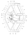
- FIG. 2 is a vertical cross-sectional view of an impeller and a bell mouth according to the present embodiment
- FIG. 4 is a perspective view of the vicinity of the root portion of the blade portion of the impeller according to the present embodiment.
- FIG. 1 An embodiment of an impeller according to the present invention will be described with reference to FIGS. 1 to 11.
- FIG. the same code
- FIG. 1 is a schematic perspective view of an indoor unit of a refrigeration cycle apparatus equipped with an impeller according to an embodiment of the present invention.
- FIG. 2 is a schematic vertical cross-sectional view of an indoor unit of a refrigeration cycle apparatus equipped with an impeller according to an embodiment of the present invention.
- the refrigeration cycle apparatus includes an indoor unit 1 installed indoors as a user side and an outdoor unit (not shown) installed outdoors as a heat source side, as shown in FIG. .
- the refrigeration cycle device includes a refrigeration cycle (not shown).
- the refrigeration cycle includes a heat source side heat exchanger (not shown), a compressor (not shown), a heat exchanger 2 on the user side, an expander (not shown), and a refrigerant that circulates the refrigerant through these devices. Piping (not shown) is provided.
- the refrigeration cycle may include a four-way valve (not shown) for switching between cooling operation and heating operation of the refrigeration cycle device.
- the indoor unit 1 accommodates a heat exchanger 2 on the user side of the refrigeration cycle.
- the outdoor unit accommodates a heat source side heat exchanger, a compressor, and a four-way valve of the refrigeration cycle.
- the expander may be housed in the indoor unit 1 or may be housed in the outdoor unit.
- the outdoor unit and the indoor unit are connected via a connecting pipe (not shown).
- the transition pipe is part of the refrigerant pipe.
- the refrigeration cycle device circulates a refrigerant between a heat exchanger on the outdoor unit side and a heat exchanger 2 on the indoor unit 1 side to harmonize indoor air.
- the installation location of the indoor unit 1 is inside the building.
- the indoor unit 1 is installed by being embedded in the indoor ceiling or suspended from the ceiling or beams.
- the indoor unit 1 includes a housing 5, a heat exchanger 2 provided inside the housing 5, and a blower 6.
- the blower device 6 includes an annular bell mouth 7 provided on the housing 5 and a turbo fan 8 that sucks air from the bell mouth 7 and blows the air onto the heat exchanger 2 .
- the indoor unit 1 includes an electric expansion valve (not shown) that is an expander of a refrigeration cycle.
- the housing 5 is a box having a rectangular top surface, four rectangular side surfaces, and a rectangular bottom surface.
- the top surface of the housing 5 is covered with a top plate 11.
- - ⁇ A turbo fan 8 is provided on the bottom surface of the top plate 11 .
- Four side surfaces of the housing 5 are covered with side plates 12 .
- the corners between the sides are beveled like a chamfer. This chamfered portion is closed with an inclined plate 13 .
- the bottom surface of the housing 5 is covered with a bottom plate 14.
- a circular suction port 16 for sucking air from below the indoor unit 1 is provided in the central portion of the bottom plate 14 .
- a plurality of rectangular outlets 17 for blowing air downward are provided on the outer edge of the bottom plate 14 .
- Each air outlet 17 extends along each side of the rectangular bottom surface of the housing 5 . Therefore, the indoor unit 1 sucks indoor air from the suction port 16 on the bottom surface of the housing 5, heat-exchanges the refrigerant and the air in the heat exchanger 2, and heats the air from the blowout port 17 on the bottom surface of the housing 5. blow out the air.
- the heat exchanger 2 is fixed to the top plate 11 of the housing 5.
- the heat exchanger 2 is, for example, of a fin-and-tube type, and includes a large number of aligned aluminum alloy fins and refrigerant pipes passing through the fins.
- the heat exchanger 2 is provided inside the housing 5 and surrounds the radially outer side of the turbo fan 8 .
- the inner peripheral surface of the heat exchanger 2 faces the turbo fan 8
- the outer peripheral surface of the heat exchanger 2 faces the inner surface of the side plate 12 .
- the heat exchanger 2 has a flat plate portion 2a facing each side plate 12 of the housing 5 and a curved plate 13 between two adjacent side plates 12 to connect the two adjacent flat plate portions 2a. and a curved plate portion 2b.
- An annular bell mouth 7 is provided at the suction port 16 of the bottom plate 14 .
- the opening edge of the bell mouth 7 on the suction side that is, the upstream end 7 a of the bell mouth 7 continues to the outer surface 14 a of the bottom plate 14 .
- the opening edge of the bell mouth 7 on the blowout side that is, the downstream end 7 b of the bell mouth 7 continues to the inner surface 14 b of the bottom plate 14 .
- An inner surface 14 b of the bottom plate 14 is flat and reaches the heat exchanger 2 from the downstream end 7 b of the bell mouth 7 .
- the outer surface 14a of the bottom plate 14 is a flat upstream side surface 18 connected to the upstream end 7a of the bellmouth 7, and the inner surface 14b of the bottom plate 14 is a flat downstream side surface 19 connected to the downstream end 7b of the bellmouth 7. be.
- a drain pan may be provided below the heat exchanger 2 to receive condensed water generated on the surface of the heat exchanger 2 .
- the moisture contained in the air passing through the heat exchanger 2 that is, the humidity in the room, condenses on the surface of the heat exchanger 2 and condenses on the heat exchanger 2 as condensed water. It adheres and drips from the heat exchanger 2.
- a drain pan receives condensed water falling from the heat exchanger 2 . Condensed water stored in the drain pan is pumped up by a drain pump (not shown) provided in the housing 5 and discharged to the outside of the indoor unit 1 through a drain pipe (not shown).
- the drain pan preferably has a concave portion for receiving condensed water in a portion where the planar portion extending from the downstream end 7b of the bell mouth 7 to the heat exchanger 2 is as close to the heat exchanger 2 as possible.
- the drain pan is preferably made of a heat insulating material integrated with the bottom plate 14 of the housing 5 .
- the turbo fan 8 includes a fan motor 22 having a rotating shaft 21 extending in the vertical direction, and an impeller 23 fixed to the rotating shaft 21 so as to rotate integrally.
- the fan motor 22 rotates the impeller 23 .
- the fan motor 22 is fixed to the inner surface of the top plate 11 of the housing 5 via fixtures 25 .
- the rotationally driven impeller 23 sucks the air around the housing 5 from the bell mouth 7 of the suction port 16, blows out the air radially in the direction along the inner surface 14b of the bottom plate 14, and directs the blown air to the heat exchanger 2. Spray.
- a maximum outer diameter A of the turbofan 8 is larger than an opening diameter B of the bell mouth 7 .
- the rotation centerline C of the impeller 23 coincides with the centerline of the rotation shaft 21 of the fan motor 22 and extends vertically with the indoor unit 1 installed.
- the compressor of the outdoor unit discharges high-temperature and high-pressure gas refrigerant and sends it to the heat exchanger (condenser) on the outdoor side.
- the outdoor-side heat exchanger exchanges heat between the refrigerant flowing therein and the outdoor air to condense the refrigerant.
- the condensed liquid refrigerant is sent to the indoor unit 1 through the refrigerant pipe.
- the indoor unit 1 expands the liquid refrigerant flowing from the refrigerant pipe with an electric expansion valve, and sends a low-temperature gas-liquid mixed refrigerant to the heat exchanger 2 (evaporator).
- the heat exchanger 2 exchanges heat between the low-temperature refrigerant flowing therein and the indoor air to gasify the refrigerant.
- the room is cooled by the low-temperature air blown out from the indoor unit 1 .
- the compressor of the outdoor unit discharges high-temperature and high-pressure gas refrigerant and sends it to the heat exchanger 2 (condenser) of the indoor unit 1 .
- the heat exchanger 2 exchanges heat between the refrigerant flowing inside and the air in the room to condense the refrigerant.
- the room is heated by the high-temperature air blown out from the indoor unit 1 .
- the impeller 23 will be described in detail.
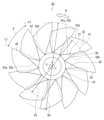
- FIG. 3 is a bottom view of the impeller according to this embodiment.
- FIG. 4 is a perspective view showing the impeller according to this embodiment from the bottom side.
- FIG. 5 is a longitudinal sectional view of the impeller and bell mouth according to this embodiment.
- the impeller 23 is substantially parallel to the downstream side 19 connected to the bell mouth 7 and extends radially. 31 , a plurality of wing portions 32 protruding from the main plate portion 31 toward the downstream side surface 19 and the bell mouth 7 and arranged in an annular shape, and a hub portion 33 provided at the center of the main plate portion 31 .
- the impeller 23 is an integrally molded product made of fiber reinforced plastic (FRP), aluminum alloy, or magnesium metal.
- the impeller 23 is made of fiber-reinforced plastic, for example, and integrally molded by hand lay-up.
- the main plate portion 31 has a flat plate shape with a substantially uniform thickness.
- the main plate portion 31 is an assembly of a plurality of petal portions 35 radially extending outward in the radial direction of the impeller 23 from the hub portion 33 .
- Each petal portion 35 has a first side portion 35a having a linear edge and a second side portion 35b having a linear edge. Or it extends in a tapered shape.
- the first side portion 35 a of each petal portion 35 is also called the first edge of the main plate portion 31
- the second side portion 35 b of each petal portion 35 is also called the second edge of the main plate portion 31 .
- the first side 35 a of one petal 35 faces the second side 35 b of the other petal 35 .
- the first side portion 35a of one petal portion 35 and the second side portion 35b of the other petal portion 35 are separated from each other in the circumferential direction of the main plate portion 31 with a gap therebetween and face each other in the circumferential direction. .
- All the petals 35 have substantially the same shape.
- the ends of the plurality of petals 35 located radially inward of the turbofan 8 that is, the root ends of the plurality of petals 35 tightly surround the outer periphery of the hub portion 33 .
- the root end of the first side portion 35 a of one petal portion 35 coincides with the root end of the second side portion 35 b of the other petal portion 35 .
- the ends of the plurality of petals 35 positioned radially outward of the turbofan 8 that is, the protruding ends of the plurality of petals 35 can be connected by a virtual circle. It corresponds to the outermost diameter D1.
- the protruding end of the petal portion 35 is a corner formed by the first side portion 35a and the second side portion 35b.
- a plurality of wing portions 32 and hub portions 33 protrude from the main plate portion 31 in the same direction.
- the hub portion 33 has a truncated cone shape that tapers away from the main plate portion 31 .
- the protrusion height of the plurality of blade portions 32 with respect to the main plate portion 31 is higher than the protrusion height of the hub portion 33 .
- the number of wings 32 that is, the number of wings is a prime number, and is 11 in this embodiment.
- the shape of all wings 32 is substantially the same.
- the plurality of wings 32 are open. That is, the impeller 23 does not have an element that connects the plurality of blades 32 in the circumferential direction, such as a shroud that connects the projecting ends 32a of the plurality of blades 32 .
- Each wing portion 32 is connected only to the main plate portion 31 and is not in contact with and is not connected to the hub portion 33 .
- a root end 32 b of each wing portion 32 is an edge of each wing portion 32 that continues to the main plate portion 31 .
- a root end 32b of each wing portion 32 continues to a first side portion 35a of each petal portion 35 .
- each wing portion 32 protrudes from the first side portion 35 a of each petal portion 35 . Therefore, the root end 32b of each wing portion 32 has the same linear shape as the first side portion 35a of each petal portion 35 and has a linear shape that matches the chord of the blade.
- Each blade portion 32 is inclined in the circumferential direction of the turbofan 8 and in the direction away from the second side portion 35b of each petal portion 35. Further, each blade portion 32 is inclined outward in the radial direction of the turbofan 8 from the root end 32b toward the projecting end 32a. Therefore, when the impeller 23 is viewed along the rotation centerline C as shown in FIG.
- the impeller 23 rotates in a direction R in which the first side portion 35a of each petal portion 35 precedes the second side portion 35b to flow air. That is, the front edge 41 of each blade 32 is positioned on the inner peripheral side of the impeller 23 , and the trailing edge 42 of each blade 32 is positioned on the outer peripheral side of the impeller 23 .
- the leading edge 41 of the blade 32 is the inner edge relatively close to the rotational centerline C of the impeller 23 and the trailing edge 42 of the blade 32 is relatively close to the rotational centerline C of the impeller 23. is the outer edge far from the
- An angle ⁇ between L1 and a second line segment L2 connecting the trailing edge 42 of the second wing portion 32, which is the other wing portion, and the rotation center line C is preferably 25 degrees or more. That is, the number of wings 32 is preferably a prime number of 13 or less, and is 11 in this embodiment.
- each wing portion 32 protrudes toward the upstream end 7a of the bell mouth 7 from the first portion 45 arranged close to the downstream side 19 and the downstream end 7b of the bell mouth 7. and a second portion 46 where the second portion 46 is located. That is, the protruding end 32 a of each wing 32 has a convex portion 47 that enters the inside of the bell mouth 7 .
- the convex portion 47 protrudes following the shape of the bell mouth 7 .
- the second portion 46 is the ridgeline of the convex portion 47 .
- the first portion 45 of the wing portion 32 and the downstream side surface 19 are arranged to face each other with an interval of about several millimeters therebetween.
- the distance between the impeller 23 and the bell mouth 7 is preferably as close as possible within the range in which the impeller 23 can rotate smoothly without interfering with the bell mouth 7 .
- each wing portion 32 is thinner than the thickness of the main plate portion 31 .
- Such a thickness relationship is compared to the case where the thickness of each wing portion 32 is the same as the thickness of the main plate portion 31 or the case where the thickness of each wing portion 32 is thicker than the thickness of the main plate portion 31.
- reduce the centrifugal force acting on the wings 32 reduces the deformation of the wing portions 32 and prevents the reduction in the air volume due to the deformation of the wing portions 32 .
- the main plate portion 31, which is thicker than each wing portion 32 reduces deformation of the wing portions 32 due to centrifugal force, and prevents reduction in air volume due to deformation of the wing portions 32.
- FIG. 6 is a perspective view of the vicinity of the root portion of the blade portion of the impeller according to this embodiment.
- FIG. 7 is a bottom view of the vicinity of the root portion of the blade portion of the impeller according to this embodiment.
- the impeller 23 is provided at the root portion of the blade portion 32 connected to the main plate portion 31 so that the front edge 41 is separated from the hub portion 33 as the main plate portion 31 is approached. It has a curved blade side curved portion 51 .
- the blade-side curved portion 51 eliminates the corner formed by the front edge 41 of the wing portion 32 and the root end 32b of the wing portion 32 .
- the blade-side curved portion 51 is formed as a notch that lacks a part of the root side of the blade portion 32 including the corner portion.
- the impeller 23 has a main plate side curved portion which is connected to the blade side curved portion 51 at the root portion connected to the hub portion 33 of the main plate portion 31 and which curves away from the nearest blade portion 32 as the hub portion 33 is approached. 52.
- the main plate side curved portion 52 eliminates the corner formed by the root end of the hub portion 33 and the root end 32 b of the wing portion 32 .
- the main plate-side curved portion 52 is formed as a notch in which a portion of the base side of the petal portion 35 including the corner portion is removed, similarly to the blade-side curved portion 51 .
- the root end 32b of the wing portion 32 and the first side portion 35a of the petal portion 35 substantially match each other. Therefore, in other words, the blade-side curved portion 51 and the main plate-side curved portion 52 are formed at the root portion of the blade portion 32 by the front edge 41 of the blade portion 32 and the first side portion 35a of the petal portion 35. Eliminate the corner formed by Further, the main plate side curved portion 52 eliminates the corner formed by the first side portion 35 a of the petal portion 35 and the root end of the hub portion 33 at the root portion of the petal portion 35 .
- main plate-side curved portion 52 is provided at the root portion of the main plate portion 31 connected to the hub portion 33, is connected to the blade-side curved portion 51, and is curved in a concave shape that is open toward the blade portion 32. good.
- a line segment extending from the root end 32b of the wing portion 32 and the first side portion 35a of the petal portion 35 and reaching the root end of the hub portion 33 is called a wing tip extension line EL1.
- a line segment extending from the leading edge 41 and reaching the root end of the hub portion 33 is called a blade leading edge extension line EL2.
- the blade tip extension line EL1 and the blade leading edge extension line EL2 substantially intersect at the root end of the hub portion 33 and converge at one point.
- a point at which the root end of the hub portion 33, the wing tip extension line EL1, and the wing leading edge extension line EL2 substantially converge is called a dense point 53. As shown in FIG.
- the dense points 53 may spread over a circular range with a diameter of about 5 mm. That is, at the dense point 53, the root end of the hub portion 33, the blade tip extension line EL1, and the blade leading edge extension line EL2 are in a circular range of 0.5% to 2.0% of the outermost diameter of the impeller 23. It would be nice if we could gather at
- an impeller without the blade side curved portion 51 and the main plate side curved portion 52 is assumed.
- the hub portion 33 , the petal portions 35 of the main plate portion 31 , and the wing portions 32 are adjacent to each other at the dense point 53 . That is, the root end of the hub portion 33, the first side portion 35a of the petal portion 35, the second side portion 35b of the other adjacent petal portion 35, the root end 32b of the wing portion 32, and the front edge 41 of the wing portion 32 They intersect substantially at the dense point 53 .
- a force applied to blade portion 32 due to rotation of impeller 23 is supported by main plate portion 31 and hub portion 33 . Therefore, the stress acting on the impeller 23 concentrates on the dense points 53 .
- the blade-side curved portion 51 and the main plate-side curved portion 52 prevent the hub portion 33 , the petal portions 35 of the main plate portion 31 , and the wing portions 32 from concentrating on the dense point 53 . That is, in the impeller 23 according to this embodiment, the hub portion 33 , the petal portions 35 of the main plate portion 31 , and the blade portions 32 do not adjoin each other at the dense point 53 .
- the blade-side curved portion 51 and the main plate-side curved portion 52 have concave shapes that are depressed in a direction away from the dense point 53 . Therefore, while the blade side curved portion 51 and the main plate side curved portion 52 slightly reduce the blade area, the dense point 53, that is, the corner where the hub portion 33, the petal portion 35 of the main plate portion 31, and the blade portion 32 contact each other Reliably reduce the stress concentrated on the part. Specifically, the blade-side curved portion 51 reliably reduces the stress that concentrates on the root portion of the blade portion 32 on the leading edge 41 side, and the main plate-side curved portion 52 is located at the root portion of the main plate portion 31 on the first side. The stress concentrated on the portion 35a side is reliably reduced.
- the blade-side curved portion 51 and the main plate-side curved portion 52 may be formed in the process of molding or molding the impeller 23, or after molding or molding the impeller 23, the main plate portion 31 and the blade portion 32 are formed by machining. may be formed by removing a part of
- the impeller 23 may include only the blade-side curved portion 51. Even in that case, it is possible to prevent the hub portion 33 , the petal portions 35 of the main plate portion 31 , and the wing portions 32 from adjoining each other at the dense point 53 .
- the angle ⁇ 1 formed by the blade side curved portion 51 and the main plate side curved portion 52 is larger than the angle ⁇ 2 formed by the blade side curved portion 51 and the first side portion 35a of the main plate portion 31, the blade side curved portion 51 and the main plate side curved portion 52 Having both of the main plate side curved portions 52 reliably reduces both the stress concentrated on the root portion of the wing portion 32 and the stress concentrated on the root portion of the main plate portion 31 .
- FIG. 8 is a perspective view of the wing portion of the impeller according to this embodiment.
- the planar shape of the blade portion 32 of the impeller 23 is close to a quadrangle, for example, a parallelogram.
- the root end 32b has a linear shape that continues to the first side portion 35a of the petal portion 35 .
- a straight line connecting points a and b in FIG. 8 is the root end 32b.
- point a is the proximal end of leading edge 41 and corresponds to dense point 53 .
- Point b is the proximal end of trailing edge 42 .
- the protruding end 32a has a non-linear shape and has a protrusion 47 that passes through the protruding end of the trailing edge 42 and protrudes in a direction away from the root end 32b with respect to an imaginary line VL parallel to the root end 32b.
- the projecting end 32a is a line connecting points c, d, and e in FIG.
- point c is the distal end of leading edge 41 and point e is the distal end of trailing edge 42 .
- a line connecting points a and c in FIG. 8 is the leading edge 41 of the wing portion 32 , and a line connecting points b and e in FIG.
- the convex portion 47 has a straight edge 48 that continues to the front edge 41 and is parallel to the root end 32 b and parallel to the main plate portion 31 , and a curved edge 49 that connects the straight edge 48 and the rear edge 42 .
- a straight edge 48 is a straight line connecting points c and d in FIG. 8
- a curved edge 49 is a curved line connecting points d and e in FIG.
- the straight edge 48 and part of the curved edge 49 that follows the bellmouth 7 are the second portion 46 of the protruding end 32a, and the remainder of the curved edge 49 is the first portion 45 located adjacent the downstream side 19. is. That is, the remainder of curvilinear edge 49 is substantially parallel to root end 32b.
- This gap is preferably 5 millimeters or less.
- FIG 9 and 10 are perspective views of the impeller according to this embodiment.
- the impeller 23 is an integrally molded product or an integrally molded composite material having fiber material 55 oriented so as to straddle the hub portion 33 and the main plate portion 31 .
- the impeller 23 is an integrally molded article or an integrally molded composite material having fiber materials 55 oriented so as to straddle the main plate portion 31 and the respective blade portions 32. It is a product.
- the impeller 23 is formed by laminating sheet-like prepregs such as UD material, which is a prepreg made of carbon fibers in one direction, and cloth material, which is a prepreg in which warp and weft threads are woven.
- the impeller 23 is autoclave molding that cures the resin in a high-temperature, high-pressure pressure vessel, or RTM (Resin Transfer Molding) molding that injects and cures the resin after setting the carbon fiber base material in the mold.
- the prepreg is placed in a preheated mold and molded by a method such as press molding in which the prepreg is cured while being pressed by a press.
- the impeller 23 may be formed by molding a resin composite material containing plant fibers by methods such as injection molding and extrusion molding. Plant fibers are oriented by resin flow during molding.
- the impeller 23 may include fiber materials 55 oriented in any direction other than the fiber materials 55 oriented as shown in FIGS. 9 and 10 .
- the impeller 23 may include fabrics 55 oriented orthogonally to the fabrics 55 shown in FIGS.
- FIG. 11 is a perspective view showing another example of the impeller according to this embodiment from the bottom side.
- the impeller 23A may include reinforcing members 58 that connect the blade portions 32 and the hub portion 33, respectively.
- the reinforcing member 58 does not have a width in the radial direction and has a substantial dimensional difference between the outer diameter and the inner diameter like the shroud of a conventional impeller, but is a linear member such as a steel wire. is.
- the reinforcing member 58 extends from the hub portion 33 to the protruding end 32a or front edge 41 of each wing portion 32 like an umbrella bone.
- the reinforcing member 58 prevents the blades 32 from collapsing radially outward of the impeller 23A due to the rotation of the impeller 23A, and reduces stress concentration at the dense point 53 .
- the impellers 23 and 23A according to the present embodiment do not have shrouds, they can be integrally molded. Therefore, the impellers 23 and 23A eliminate factors that cause defects such as poor welding and poor adhesion when the separate shroud is joined to the blade portion, and when joining the separate shroud to the blade portion 32, The amount of imbalance in rotational balance can be reduced compared to the
- the impellers 23 and 23A according to this embodiment are provided with a plurality of blade portions 32 that are connected only to the main plate portion 31 . Therefore, the impellers 23 and 23A can be easily made lighter than conventional impellers having shrouds and frames, and can eliminate obstacles to air flow.
- the impellers 23 and 23A according to the present embodiment are provided with the wing portions 32 having root ends 32b that are continuous with the first side portions 35a of the respective petal portions 35, which are part of the edge of the main plate portion 31. . Therefore, the impellers 23 and 23A can smoothly blow out the flow of air that has been given energy by the blades 32 .
- the impellers 23 and 23A have a first side portion 35a of the petal portion 35 and a second side portion 35b of the petal portion 35 facing each other across a gap in the circumferential direction of the main plate portion 31. there is Therefore, the impellers 23 and 23A can blow out the air energized by the blades 32 through the gaps between the adjacent petals 35 . Such air flow improves the air blowing function of the impeller 23 .
- the gaps between the adjacent petals 35 improve the workability of each process and facilitate mold release when integrally molding the impellers 23 and 23A.
- the impellers 23 and 23A according to this embodiment are provided with a plurality of blade portions 32 having a higher protrusion height than the hub portion 33. Therefore, the impeller 23 can reduce the airflow resistance of the hub portion 33 and easily push out the airflow with the wing portions 32 .
- each blade portion 32 of the impellers 23 and 23A is thinner than the thickness of the main plate portion 31 . Therefore, the impellers 23 and 23A reduce the deformation of the wing portions 32 and prevent the air volume from decreasing due to the deformation of the wing portions 32 .
- the impellers 23 and 23A according to the present embodiment have blade-side curved portions 51 at the root portions of the respective blade portions 32.
- the front edges 41 curve away from the hub portion 33 as they approach the main plate portion 31. there is Therefore, the impellers 23 and 23A do not have corners formed by the front edges 41 of the blades 32 and the first side portions 35a of the petals 35. reliably reduce stresses concentrated in
- the impellers 23 and 23A according to the present embodiment are connected to the blade-side curved portion 51 at the root portion of the main plate portion 31, and the main plate side curved away from the nearest blade portion 32 as it approaches the hub portion 33. It has a curved portion 52 . Therefore, the impellers 23 and 23A do not have a corner formed by the root end of the hub portion 33 and the first side portion 35a of the petal portion 35. Reliably reduces concentrated stress.
- the impeller 23A includes a reinforcing member 58 that connects the blade portion 32 and the hub portion 33 together. Therefore, even if the impeller 23A does not have a shroud, the weight of the entire impeller 23 is reduced, the influence of the centrifugal force on the wing portion 32 is reduced, the decrease in the air volume is suppressed, and the wing portion 32 is reduced. This prevents collision between the bell mouth 7 and the wings 32 due to deformation.
- the impeller 23A prevents the blades 32 from collapsing radially outwardly of the impeller 23A due to the rotation of the impeller 23A. It is possible to reliably reduce the stress concentrated on the root of the
- impellers 23 and 23A are an integrally molded article or an integrally molded article of composite material having the fiber material 55 oriented so as to straddle the hub portion 33 and the main plate portion 31 . Therefore, impellers 23 and 23A can prevent main plate portion 31 and blade portion 32 from easily scattering even if the boundary portion between hub portion 33 and main plate portion 31 should be damaged.
- the impellers 23 and 23A according to the present embodiment are integrally molded articles or integrally molded articles of composite material having fiber materials 55 oriented so as to straddle the main plate portion 31 and the respective blade portions 32 . Therefore, even if the boundary between the main plate portion 31 and the blade portion 32 should be damaged, the impellers 23 and 23A can prevent the blade portion 32 from scattering easily.
- impellers 23 and 23A it is possible to reduce the concentration of stress at the portion where the hub portion 33 and the blade portion 32 are densely packed without providing a fillet in the base portion of the blade portion 32. .
Landscapes
- Engineering & Computer Science (AREA)
- Mechanical Engineering (AREA)
- General Engineering & Computer Science (AREA)
- Structures Of Non-Positive Displacement Pumps (AREA)
Priority Applications (2)
| Application Number | Priority Date | Filing Date | Title |
|---|---|---|---|
| CN202280066635.4A CN118043560A (zh) | 2021-11-01 | 2022-10-21 | 叶轮 |
| JP2023556403A JP7752185B2 (ja) | 2021-11-01 | 2022-10-21 | 羽根車 |
Applications Claiming Priority (2)
| Application Number | Priority Date | Filing Date | Title |
|---|---|---|---|
| JP2021-178646 | 2021-11-01 | ||
| JP2021178646 | 2021-11-01 |
Publications (1)
| Publication Number | Publication Date |
|---|---|
| WO2023074578A1 true WO2023074578A1 (ja) | 2023-05-04 |
Family
ID=86159876
Family Applications (1)
| Application Number | Title | Priority Date | Filing Date |
|---|---|---|---|
| PCT/JP2022/039333 Ceased WO2023074578A1 (ja) | 2021-11-01 | 2022-10-21 | 羽根車 |
Country Status (3)
| Country | Link |
|---|---|
| JP (1) | JP7752185B2 (https=) |
| CN (1) | CN118043560A (https=) |
| WO (1) | WO2023074578A1 (https=) |
Citations (3)
| Publication number | Priority date | Publication date | Assignee | Title |
|---|---|---|---|---|
| JPS51147002A (en) * | 1975-06-12 | 1976-12-17 | Aisin Seiki Co Ltd | Pump impeller for water pump |
| JP2013527046A (ja) * | 2009-11-23 | 2013-06-27 | ヌオーヴォ ピニォーネ ソシエタ ペル アチオニ | 遠心羽根車用金型、金型挿入物、および遠心羽根車を構築するための方法 |
| WO2021059328A1 (ja) * | 2019-09-24 | 2021-04-01 | 東芝キヤリア株式会社 | 冷凍サイクル装置の室内機、および羽根車 |
Family Cites Families (2)
| Publication number | Priority date | Publication date | Assignee | Title |
|---|---|---|---|---|
| JPS51143108U (https=) * | 1975-05-13 | 1976-11-17 | ||
| JPS5252210A (en) * | 1975-10-24 | 1977-04-26 | Honda Motor Co Ltd | Manufacturing method of centrifugal ventilating fan |
-
2022
- 2022-10-21 JP JP2023556403A patent/JP7752185B2/ja active Active
- 2022-10-21 CN CN202280066635.4A patent/CN118043560A/zh active Pending
- 2022-10-21 WO PCT/JP2022/039333 patent/WO2023074578A1/ja not_active Ceased
Patent Citations (3)
| Publication number | Priority date | Publication date | Assignee | Title |
|---|---|---|---|---|
| JPS51147002A (en) * | 1975-06-12 | 1976-12-17 | Aisin Seiki Co Ltd | Pump impeller for water pump |
| JP2013527046A (ja) * | 2009-11-23 | 2013-06-27 | ヌオーヴォ ピニォーネ ソシエタ ペル アチオニ | 遠心羽根車用金型、金型挿入物、および遠心羽根車を構築するための方法 |
| WO2021059328A1 (ja) * | 2019-09-24 | 2021-04-01 | 東芝キヤリア株式会社 | 冷凍サイクル装置の室内機、および羽根車 |
Also Published As
| Publication number | Publication date |
|---|---|
| JPWO2023074578A1 (https=) | 2023-05-04 |
| JP7752185B2 (ja) | 2025-10-09 |
| CN118043560A (zh) | 2024-05-14 |
Similar Documents
| Publication | Publication Date | Title |
|---|---|---|
| US10900360B2 (en) | Fan, outdoor unit, and refrigeration cycle apparatus | |
| WO2010143341A1 (ja) | ターボファンおよび空気調和機 | |
| US11674520B2 (en) | Centrifugal fan and air-conditioning apparatus | |
| CN110945251B (zh) | 螺旋桨式风扇、送风装置以及制冷循环装置 | |
| US11976872B2 (en) | Axial flow fan, air-sending device, and refrigeration cycle apparatus | |
| JP6945739B2 (ja) | 多翼送風機及び空気調和装置 | |
| JP5425270B2 (ja) | ターボファンおよび空気調和機 | |
| WO2023074578A1 (ja) | 羽根車 | |
| JP7343601B2 (ja) | 冷凍サイクル装置の室内機、および羽根車 | |
| KR102655373B1 (ko) | 원심 압축기용 2 부품 분할 스크롤 | |
| JP7458552B2 (ja) | 送風装置 | |
| AU2017427465A1 (en) | Propeller fan, air-sending device, and refrigeration cycle apparatus | |
| EP3660405B1 (en) | Air conditioner | |
| JP6745902B2 (ja) | 送風機、室外機及び冷凍サイクル装置 | |
| KR102206818B1 (ko) | 프로펠러 팬, 실외기 및 냉동 사이클 장치 | |
| US20220325905A1 (en) | Air handling unit and fan therefor | |
| EP4098885A1 (en) | Centrifugal blower and air conditioner provided with same | |
| KR100459129B1 (ko) | 천장형 공기조화기의 실내기 | |
| CN117222815A (zh) | 送风机、空调装置和制冷循环装置 | |
| WO2016038690A1 (ja) | 空気調和装置用室内機および空気調和装置 |
Legal Events
| Date | Code | Title | Description |
|---|---|---|---|
| 121 | Ep: the epo has been informed by wipo that ep was designated in this application |
Ref document number: 22886905 Country of ref document: EP Kind code of ref document: A1 |
|
| WWE | Wipo information: entry into national phase |
Ref document number: 2023556403 Country of ref document: JP |
|
| WWE | Wipo information: entry into national phase |
Ref document number: 202280066635.4 Country of ref document: CN |
|
| NENP | Non-entry into the national phase |
Ref country code: DE |
|
| 122 | Ep: pct application non-entry in european phase |
Ref document number: 22886905 Country of ref document: EP Kind code of ref document: A1 |