WO2023068132A1 - 自律走行制御システム、自律走行制御装置、自律走行装置、自律走行制御方法、自律走行制御プログラム - Google Patents
自律走行制御システム、自律走行制御装置、自律走行装置、自律走行制御方法、自律走行制御プログラム Download PDFInfo
- Publication number
- WO2023068132A1 WO2023068132A1 PCT/JP2022/038021 JP2022038021W WO2023068132A1 WO 2023068132 A1 WO2023068132 A1 WO 2023068132A1 JP 2022038021 W JP2022038021 W JP 2022038021W WO 2023068132 A1 WO2023068132 A1 WO 2023068132A1
- Authority
- WO
- WIPO (PCT)
- Prior art keywords
- autonomous
- executing
- user
- mode
- movement
- Prior art date
- Legal status (The legal status is an assumption and is not a legal conclusion. Google has not performed a legal analysis and makes no representation as to the accuracy of the status listed.)
- Ceased
Links
Images


Classifications
-
- B—PERFORMING OPERATIONS; TRANSPORTING
- B60—VEHICLES IN GENERAL
- B60T—VEHICLE BRAKE CONTROL SYSTEMS OR PARTS THEREOF; BRAKE CONTROL SYSTEMS OR PARTS THEREOF, IN GENERAL; ARRANGEMENT OF BRAKING ELEMENTS ON VEHICLES IN GENERAL; PORTABLE DEVICES FOR PREVENTING UNWANTED MOVEMENT OF VEHICLES; VEHICLE MODIFICATIONS TO FACILITATE COOLING OF BRAKES
- B60T7/00—Brake-action initiating means
- B60T7/12—Brake-action initiating means for automatic initiation; for initiation not subject to will of driver or passenger
-
- B—PERFORMING OPERATIONS; TRANSPORTING
- B60—VEHICLES IN GENERAL
- B60W—CONJOINT CONTROL OF VEHICLE SUB-UNITS OF DIFFERENT TYPE OR DIFFERENT FUNCTION; CONTROL SYSTEMS SPECIALLY ADAPTED FOR HYBRID VEHICLES; ROAD VEHICLE DRIVE CONTROL SYSTEMS FOR PURPOSES NOT RELATED TO THE CONTROL OF A PARTICULAR SUB-UNIT
- B60W50/00—Details of control systems for road vehicle drive control not related to the control of a particular sub-unit, e.g. process diagnostic or vehicle driver interfaces
- B60W50/08—Interaction between the driver and the control system
-
- B—PERFORMING OPERATIONS; TRANSPORTING
- B60—VEHICLES IN GENERAL
- B60W—CONJOINT CONTROL OF VEHICLE SUB-UNITS OF DIFFERENT TYPE OR DIFFERENT FUNCTION; CONTROL SYSTEMS SPECIALLY ADAPTED FOR HYBRID VEHICLES; ROAD VEHICLE DRIVE CONTROL SYSTEMS FOR PURPOSES NOT RELATED TO THE CONTROL OF A PARTICULAR SUB-UNIT
- B60W60/00—Drive control systems specially adapted for autonomous road vehicles
-
- G—PHYSICS
- G05—CONTROLLING; REGULATING
- G05D—SYSTEMS FOR CONTROLLING OR REGULATING NON-ELECTRIC VARIABLES
- G05D1/00—Control of position, course, altitude or attitude of land, water, air or space vehicles, e.g. using automatic pilots
-
- G—PHYSICS
- G05—CONTROLLING; REGULATING
- G05D—SYSTEMS FOR CONTROLLING OR REGULATING NON-ELECTRIC VARIABLES
- G05D1/00—Control of position, course, altitude or attitude of land, water, air or space vehicles, e.g. using automatic pilots
- G05D1/02—Control of position or course in two dimensions
-
- G—PHYSICS
- G08—SIGNALLING
- G08G—TRAFFIC CONTROL SYSTEMS
- G08G1/00—Traffic control systems for road vehicles
- G08G1/09—Arrangements for giving variable traffic instructions
Definitions
- the present disclosure relates to technology for controlling an autonomous mobile device capable of autonomous travel.
- Patent Document 1 discloses a traveling carriage that can be self-propelled by a motor. This traveling truck performs a self-propelled operation in which the drive wheels are driven to rotate by a motor, and a manual operation in which the drive wheels are brought into a brake-released state so that they can be operated by an external force.
- Patent Literature 1 only permits the user's operation by simply releasing the brakes on the driving wheels. Therefore, Patent Document 1 has room for improvement in terms of facilitating the operation by the user.
- An object of the present disclosure is to provide an autonomous driving control system that can be easily operated by the user. Another object of the present disclosure is to provide an autonomous cruise control device that can be easily operated by a user. Yet another object of the present disclosure is to provide an autonomous mobile device that can be easily operated by a user. Yet another object of the present disclosure is to provide an autonomous travel control method that enables easy user operation. Still another object of the present disclosure is to provide an autonomous travel control program that can be easily operated by a user.
- a first aspect of the present disclosure is an autonomous traveling control system that has a processor and controls an autonomous traveling device capable of executing autonomous traveling,
- the processor executing an autonomous driving mode for executing autonomous driving; executing a stop mode that restricts movement of the autonomous mobile device; executing a user operation mode in which movement restrictions are released and a user's movement operation is accepted; is configured to run
- Executing the user operation mode includes causing the autonomous mobile device to output a driving force according to the movement operation by the user.
- a second aspect of the present disclosure is an autonomous traveling control device that has a processor and controls an autonomous traveling device capable of executing autonomous traveling,
- the processor executing an autonomous driving mode for executing autonomous driving; executing a stop mode that restricts movement of the autonomous mobile device; executing a user operation mode in which movement restrictions are released and a user's movement operation is accepted; is configured to run
- Executing the user operation mode includes causing the autonomous mobile device to output a driving force according to the movement operation by the user.
- a third aspect of the present disclosure is an autonomous mobile device having a processor and capable of autonomous travel,
- the processor executing an autonomous driving mode for executing autonomous driving; executing a stop mode that regulates movement; executing a user operation mode in which movement restrictions are released and a user's movement operation is accepted; is configured to run Executing the user operation mode includes outputting a driving force according to the movement operation by the user.
- a fourth aspect of the present disclosure is an autonomous travel control method executed by a processor to control an autonomous travel device capable of autonomous travel, comprising: executing an autonomous driving mode for executing autonomous driving; executing a stop mode that restricts movement of the autonomous mobile device; executing a user operation mode in which movement restrictions are released and a user's movement operation is accepted; including Executing the user operation mode includes causing the autonomous mobile device to output a driving force according to the movement operation by the user.
- a fifth aspect of the present disclosure is an autonomous traveling control program stored in a storage medium for controlling an autonomous traveling device capable of executing autonomous traveling, and including instructions to be executed by a processor, the instruction is executing an autonomous driving mode for executing autonomous driving; executing a stop mode that restricts movement of the autonomous mobile device; releasing movement restrictions and executing a user operation mode in which a user's movement operation is accepted; including Executing the user operation mode includes causing the autonomous mobile device to output a driving force according to the movement operation by the user.
- the autonomous mobile device outputs a driving force according to the movement operation by the user in the user operation mode. Therefore, this driving force can reduce the burden on the user in the user operation mode. Therefore, it may be possible to facilitate the operation by the user.
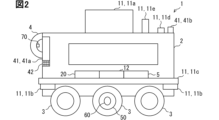
- FIG. 1 is a schematic diagram showing an autonomous mobile device to which a first embodiment is applied;
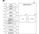
- FIG. 1 is a block diagram showing a functional configuration of an autonomous cruise control system according to a first embodiment;
- FIG. It is a flowchart which shows the process in autonomous driving mode among the autonomous driving control methods by 1st embodiment.
- It is a flowchart which shows the process in stop mode among the autonomous driving control methods by 1st embodiment.
- 4 is a flowchart showing processing in a user operation mode of the autonomous travel control method according to the first embodiment;
- It is a flowchart which shows the switching process from a stop mode to an autonomous driving mode among the autonomous driving control methods by 1st embodiment.
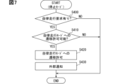
- FIG. 7 is a flowchart showing switching processing from a user operation mode to a stop mode in the autonomous travel control method according to the first embodiment;
- FIG. It is a flowchart which shows the switching process from autonomous driving mode to stop mode among the autonomous driving control methods by 1st embodiment.
- 4 is a flowchart showing a switching process from a stop mode to a user operation mode in the autonomous travel control method according to the first embodiment;
- It is a schematic diagram which shows the autonomous mobile device to which 2nd embodiment is applied.
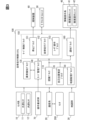
- It is a block diagram which shows the functional structure of the autonomous driving control system by 2nd embodiment.
- the autonomous traveling control system 100 of the first embodiment shown in FIG. 1 controls traveling of the autonomous traveling device 1 shown in FIG.
- the autonomous mobile device 1 is, for example, a delivery robot that travels on roads and delivers packages.
- the operation of the autonomous mobile device 1 is managed through communication with an external center 200 .
- the autonomous mobile device 1 may be a physical distribution robot that transports packages in a warehouse that stores the packages.
- the autonomous mobile device 1 includes a vehicle body 2 having a space for storing luggage therein, and a plurality of driving wheels 3 provided on the vehicle body 2 .
- the body 2 is provided with a grip portion 4 .
- the grip part 4 is installed, for example, at the rear part of the vehicle body 2 .
- the grip part 4 is a grip gripped by a user who operates the autonomous mobile device 1 to move it.
- the autonomous mobile device 1 is a mobile body that travels using a battery 5 built into a vehicle body 2 as a drive source.
- the autonomous mobile device 1 includes a sensor system 10, a communication system 20, a map database (hereinafter referred to as "DB") 30, an information presentation system 40, a motor control unit 50, a regulation device 60, and an operation request switch 70 shown in FIG. is installed.
- the sensor system 10 acquires sensor information that can be used by the autonomous traveling control system 100 by detecting the external and internal worlds of the autonomous traveling device 1 .
- the sensor system 10 includes an external sensor 11 and an internal sensor 12 .
- the external sensor 11 acquires external world information that can be used by the autonomous driving control system 100 from the external environment that is the surrounding environment of the autonomous driving device 1 .
- the external world sensor 11 may acquire external world information by detecting a target existing in the external world of the autonomous mobile device 1 .
- the target detection type external sensor 11 includes an optical sensor 11a such as a camera and LiDAR (Light Detection and Ranging/Laser Imaging Detection and Ranging), and a sonar 11b.
- the target detection type external sensor 11 may include a radar. Further, the external sensor 11 may include a contact sensor 11c that detects contact with surrounding objects.
- the external sensor 11 may acquire external world information by monitoring the state of the external environment.
- the environment monitoring type external sensor 11 is an environment sensor 11e including at least one of a temperature sensor, a thermo camera, a wind sensor, and a water intrusion sensor.
- the external sensor 11 may include a positioning type sensor that acquires external world information by receiving positioning signals from satellites of the GNSS (Global Navigation Satellite System) that exist outside the autonomous mobile device 1.
- the positioning type external sensor 11 is, for example, a GNSS receiver 11d.
- the inner world sensor 12 acquires inner world information that can be used by the autonomous mobile control system 100 from the inner world that is the internal environment of the autonomous mobile device 1 .
- the inner world sensor 12 may acquire inner world information by detecting a specific motion physical quantity in the inner world of the autonomous mobile device 1 .
- the physical quantity sensing type internal sensor 12 is at least one of, for example, a running speed sensor, an acceleration sensor, a gyro sensor, and the like.
- the communication system 20 acquires communication information that can be used by the autonomous driving control system 100 by wireless communication.
- the communication system 20 may transmit and receive communication signals with a V2X system existing outside the autonomous mobile device 1 .
- the V2X type communication system 20 is, for example, at least one of a DSRC (Dedicated Short Range Communications) communication device, a cellular V2X (C-V2X) communication device, and the like. It can also be said that the V2X type communication system 20 is a sensor that acquires external world information through communication.
- the communication system 20 may transmit and receive communication signals to and from terminals existing in the inner world of the autonomous mobile device 1 .
- the terminal communication type communication system 20 is, for example, at least one of Bluetooth (registered trademark) equipment, Wi-Fi (registered trademark) equipment, infrared communication equipment, and the like.
- the map DB 30 stores map information that can be used by the autonomous driving control system 100.
- the map DB 30 includes at least one type of non-transitory tangible storage medium, such as semiconductor memory, magnetic medium, and optical medium.
- the map DB 30 may be a database of a locator that estimates the self-state quantity including the self-position of the autonomous mobile device 1 .
- the map DB 30 may be a database of a navigation unit that navigates the travel route of the autonomous mobile device 1 .
- the map DB 30 may be configured by combining a plurality of types of these databases.
- the map DB 30 acquires and stores the latest map information through communication with the external center 200 via the V2X type communication system 20, for example.
- the map information is two-dimensional or three-dimensional data as information representing the traveling environment of the autonomous mobile device 1 .
- the three-dimensional map data digital data of a high-precision map should be adopted.
- the map information may include road information representing at least one of the position, shape, road surface condition, and the like of the road itself.
- the map information may include sign information representing at least one of the position and shape of signs attached to roads and lane markings, for example.
- the map information may include structure information representing at least one of the positions and shapes of buildings facing roads and traffic lights, for example.
- the information presentation system 40 presents notification information to people around the autonomous mobile device 1 .
- the information presentation system 40 may be a visual presentation unit 41 that presents notification information by stimulating the vision of surrounding people.
- the visual presentation unit 41 may include, for example, a monitor device 41a that stimulates vision by displaying video or images, and a light emitting unit 41b that stimulates vision by emitting light from a lamp.
- the monitor device 41 a is provided, for example, at the rear portion of the vehicle body 2 and presents notification information to surrounding persons positioned behind the autonomous mobile device 1 .
- the monitor device 41a may allow a peripheral person to input information using a touch panel, operation buttons, or the like.
- the monitor device 41a may be capable of inputting an inquiry (to be described later) to the center 200 regarding transition to the user operation mode.
- the information presentation system 40 may be an auditory presentation unit 42 that presents notification information by stimulating the auditory sense of the occupant.
- the auditory presentation unit 42 is, for example, at least one type of speaker, buzzer, vibration unit, and the like.
- the information presentation system 40 may include a tactile presentation unit that presents notification information by stimulating the occupant's skin sensation.
- the skin sensation stimulated by the tactile sense presentation unit includes at least one of tactile sense, temperature sense, wind sense, and the like.
- the tactile sense presentation unit is, for example, a vibration unit or the like built in the grip portion 4 .
- the motor control unit 50 is a control unit that controls the drive motor that drives the drive wheels 3 to rotate.
- the motor control unit 50 is provided for each of the left and right drive wheels 3 and controls energization of the drive motor based on a control command (current command value) from the autonomous driving control system 100 .
- the regulation device 60 is a device that regulates movement of the autonomous mobile device 1 by an external force.
- the restricting device 60 has a so-called mechanical lock mechanism that mechanically restricts the rotation of the drive wheels 3 .
- the regulation device 60 is provided by an electromagnetic brake.
- the operation request switch 70 is a switch for requesting the autonomous mobile device 1, which is in a stopped state due to a stop mode described later, to switch to a user operation mode described later.
- the operation request switch 70 is provided on the grip portion 4 .
- the operation request switch 70 is operated by an arbitrary operator (user) among surrounding persons, and outputs an operation request for the autonomous mobile device 1 in the user operation mode to the autonomous mobile control system 100 .
- the operation request switch 70 may be, for example, a push button switch. Alternatively, the operation request switch 70 may be a toggle switch or a rocker switch.
- Autonomous driving control system 100 includes sensor system 10, communication system 20, map DB 30, information presentation system via at least one of LAN (Local Area Network) line, wire harness, internal bus, wireless communication line, etc. 40 , the motor control unit 50 , the regulation device 60 and the operation request switch 70 .
- the autonomous cruise control system 100 includes at least one dedicated computer.
- the dedicated computer that configures the autonomous driving control system 100 may be an operation control ECU (Electronic Control Unit) that controls the operation of the autonomous driving device 1 .
- a dedicated computer that configures the autonomous travel control system 100 may be a navigation ECU that navigates the travel route of the autonomous travel device 1 .
- a dedicated computer that configures the autonomous traveling control system 100 may be a locator ECU that estimates the self-state quantity of the autonomous traveling device 1 .
- the dedicated computer configuring the autonomous travel control system 100 may be an actuator ECU that controls the travel actuators of the autonomous travel device 1 .
- the dedicated computer that configures the autonomous traveling control system 100 may be an HCU (HMI (Human Machine Interface) Control Unit) that controls information presentation in the autonomous traveling device 1 .
- the dedicated computer that configures the autonomous driving control system 100 may be a computer other than the autonomous mobile device 1 that configures the center 200 or a mobile terminal that can communicate via the V2X type communication system 20, for example.
- a dedicated computer that constitutes the autonomous driving control system 100 has at least one memory 101 and at least one processor 102 .
- the memory 101 stores computer-readable programs, data, etc., non-temporarily, and includes at least one type of non-transitory storage medium such as a semiconductor memory, a magnetic medium, and an optical medium. tangible storage medium).
- Processor 102 is, for example, CPU (Central Processing Unit), GPU (Graphics Processing Unit), RISC (Reduced Instruction Set Computer)-CPU, DFP (Data Flow Processor), GSP (Graph Streaming Processor), etc. At least one type as a core.
- the processor 102 executes a plurality of instructions contained in the autonomous running control program stored in the memory 101 to control the behavior of the autonomous running device 1.
- the autonomous traveling control system 100 constructs a plurality of functional blocks for controlling the behavior of the autonomous traveling device 1 .
- the plurality of functional blocks constructed in the autonomous driving control system 100 include a recognition block 110, a self-position estimation block 120, a map distribution block 130, an abnormality detection block 135, a mode management block 140, and a mode control block. 150, and a notification block 160 are included.
- the recognition block 110 acquires detection information from multiple external sensors 11 .
- a recognition block 110 integrates a plurality of pieces of detection information and recognizes information about surrounding objects (peripheral object information).
- the peripheral object information includes, for example, the position and size of the peripheral object.
- the self-position estimation block 120 estimates the self-position of the autonomous mobile device 1 .
- the self-location estimation block 120 may estimate the self-location based on the positioning information of the GNSS receiver 11d.
- the self-position estimation block 120 may estimate the self-position by dead reckoning (dead reckoning/autonomous navigation) based on the detection information of the internal sensor 12 .
- the self-position estimation block 120 may estimate the self-position by matching the detection information of the external sensor 11 and the map information.
- the self-location estimation block 120 may combine the multiple self-location estimation techniques described above to estimate the self-location.
- the self-position estimation block 120 outputs the estimated self-position together with the traveling direction of the autonomous mobile device 1 and the traveling speed of the autonomous mobile device 1 .
- the map distribution block 130 extracts map information about the surroundings of the autonomous mobile device 1 from the map DB based on the estimated self-location.
- the anomaly detection block 135 detects external anomalies that occur outside the autonomous mobile device 1 .
- external anomalies include at least one of natural disasters such as flooding, strong winds, and earthquakes, and man-made disasters such as accidents and fires that occur outside the autonomous mobile device 1 .
- the mode management block 140 manages the control mode of the autonomous mobile device 1. Specifically, the mode management block 140 determines whether or not to allow control mode switching among the autonomous driving mode, the stop mode, and the user operation mode, and switches the control mode.
- Autonomous driving mode is a mode in which autonomous driving control is executed.
- autonomous travel mode autonomous travel to a destination given from the center 200 is carried out by controlling the drive motor.
- the stop mode is a mode that regulates the movement of the autonomous mobile device 1 due to an external force. Specifically, in the stop mode, the stop state is maintained at the stop point and mechanical movement is restricted by the restriction device 60 .
- the user operation mode is a mode that accepts movement operations by the user.
- the user is a person who wishes to move the autonomous mobile device 1 among those around the autonomous mobile device 1 .
- the locked state of the driving wheels 3 by the restricting device 60 is released.
- the autonomous mobile device 1 is caused to output a driving force according to the movement operation by the user.
- the driving force corresponding to the external force applied to the autonomous mobile device 1 by the user is output. That is, in the user operation mode, a driving force in a desired direction is output in response to an operation such as direct pushing or pulling of the autonomous mobile device 1 in a desired direction by the user.
- This user operation mode is an example of an "external force operation mode.”
- the mode management block 140 manages the control mode to be executed by appropriately switching the mode allowed by the autonomous mobile device 1 from among the above modes (details will be described later). In the following, switching of control modes may be referred to as transition of control modes.
- the mode control block 150 includes, as sub-blocks, a stop block 151 for executing the stop mode, an autonomous driving block 152 for executing the autonomous driving mode, and a user operation block 153 for executing the user operation mode.
- the notification block 160 executes various notifications while the autonomous mobile device 1 is running.
- the notification block 160 executes notification to people around the autonomous mobile device 1 via the information presentation system 40 .
- the notification block 160 executes notification to the center 200 via the V2X type communication system 20 . The details of the notification performed by notification block 160 will be described later.
- Each "S" in each processing flow below means a plurality of steps executed by a plurality of instructions included in the autonomous driving control program.
- the self-position estimation block 120 estimates the self-position of the autonomous mobile device 1 .
- the recognition block 110 acquires and integrates (sensor fusion) detection information from the plurality of external sensors 11, thereby recognizing surrounding object information.
- the map distribution block 130 extracts map information about the surroundings of the autonomous mobile device 1 from the map DB 30 based on the estimated self-location.
- the autonomous travel block 152 determines the travel route based on the surrounding object information, self-position, map information, and destination point.
- the autonomous travel block 152 determines a current command value so that the vehicle travels along the determined travel route, and outputs the command value to the motor control unit 50.
- FIG. By repeating the flow described above, the autonomous driving control system 100 executes autonomous driving to the destination point while sequentially updating the driving route.
- the stop block 151 calculates and outputs a current command value for continuing the stop at the stop position.
- the current command value is calculated based on Equation (1) below.
- the stop block 151 determines whether or not the conditions for stopping the autonomous mobile device 1 are satisfied.
- the stop condition is a condition for determining that the autonomous mobile device 1 has stopped.
- the stop condition is that the running speed is equal to or less than a threshold value (for example, 3 km/h) or continues for a predetermined time. If it is determined that the stop condition is not met, the flow returns to S200.
- the flow proceeds to S220.
- the stop block 151 outputs a mechanical lock request to the regulation device 60 . After the autonomous mobile device 1 is reliably stopped at the stop position by the processing in the stop mode described above, movement due to external force is restricted by the mechanical lock.
- the user operation block 153 calculates the rotational speed of the drive motor for the drive wheels 3.
- the user operation block 153 may calculate the rotation speed from the motor rotation speed detected by the rotation speed sensor installed on the drive motor.
- the user operation block 153 calculates and outputs a current command value (assist command value) in the moving direction due to the external force according to the rotational speed.
- the correspondence relationship with the rotation speed is defined in advance by a function, table, or the like.
- the assist command value may be determined according to the gradient of the road surface in addition to the rotational speed.
- the assist command value may include a current command value for outputting a driving force in a direction against a component of gravity parallel to the road surface.
- the mode management block 140 determines whether or not there is an autonomous travel request. An autonomous travel request is transmitted from the center 200 and acquired via the communication system 20 . If it is determined that there is no autonomous travel request, this flow ends and the stop mode continues. On the other hand, if it is determined that there is an autonomous travel request, the flow proceeds to S410.
- the mode management block 140 determines whether the transition to the autonomous driving mode can be permitted, that is, whether the transition can be permitted. For example, the mode management block 140 may determine that transition can be permitted when a stop condition in the stop mode is satisfied. Alternatively, the mode management block 140 may determine that the transition can be permitted when there is no external abnormality or when the abnormality is resolved. Alternatively, the mode management block 140 may determine that the transition can be permitted when there are no obstacles that impede travel. Note that if it is determined that the transition to the autonomous driving mode cannot be permitted, this flow ends and the stop mode continues. If it is determined that the transition can be permitted, the flow proceeds to S430.
- the mode management block 140 provides the autonomous driving block 152 with permission to transition to the autonomous driving mode.
- the notification block 160 notifies the start of the autonomous driving mode to the outside.
- the notification block 160 presents a voice message on the audio presentation unit 42 that notifies the start of driving and the attention call, such as "The vehicle is moving, please be careful.”
- Notification block 160 may visually present similar content in visual presentation unit 41 .
- the notification block 160 may notify the center 200 of information regarding the transition to the autonomous driving mode.
- the mode management block 140 determines whether or not the user's movement operation is continuing in the user operation mode. For example, the mode management block 140 may determine that the movement operation continues when a predetermined time has passed without the autonomous mobile device 1 being moved by an external force. Alternatively, the mode management block 140 may determine that the movement operation continues when the operation request switch 70 is on. If it is determined that the movement operation continues, this flow ends and the user operation mode continues. On the other hand, if it is determined that the movement operation is suspended, the flow proceeds to S510.
- the mode management block 140 provides the user operation block 153 with permission to transition to the user operation mode.
- the notification block 160 notifies the start of the user operation mode to the outside.
- the notification block 160 may perform notification similar to the notification in S430.
- FIG. 9 Each flow of FIG.9 and FIG.10 is repeatedly performed in parallel during execution of autonomous driving mode.
- the abnormality detection block 135 determines whether there is a stop request from the center 200 due to an external abnormality. If there is no stop request, this flow ends and the autonomous driving mode continues.
- the flow moves to S610.
- the autonomous driving block 152 executes emergency evacuation processing by autonomous driving. Specifically, in the emergency evacuation process, the autonomous travel block 152 determines a stop point and executes autonomous travel control so that the traveling speed becomes zero at that point.
- the emergency evacuation process can also be said to be a preparatory process for transitioning to a stop state in which movement in the stop mode is restricted.
- the mode management block 140 provides the stop block 151 with permission to transition to the stop mode.
- the abnormality detection block 135 sets the external abnormality flag to ON.
- the notification block 160 notifies the information related to the transition to the stop mode to the outside.
- the notification block 160 presents a voice message, such as "Stop, please move away", through the auditory presentation unit 42, notifying that the autonomous mobile device 1 is to be moved away from the autonomous mobile device 1.
- Notification block 160 may visually present similar content in visual presentation unit 41 .
- the notification block 160 may also notify the center 200 of information regarding the transition to the stop mode.
- the abnormality detection block 135 determines whether or not an external abnormality is detected by the external sensor 11 or the communication system 20, which is a sensor mounted on the autonomous mobile device 1, that is, whether or not detection information is acquired.
- external abnormality detection information includes external abnormality imaging information by a camera, abnormal temperature detection information by a thermometer or thermo camera, strong wind detection information by an anemometer, flood detection information by a flood sensor, and V2X type communication. It includes at least one kind of detection information of communication interruption with the center 200 by the system 20 . If the external abnormality detection information is not acquired, this flow ends and the autonomous driving mode continues.
- the flow proceeds to S710.
- the notification block 160 notifies the center 200 of the occurrence of an external abnormality.
- the subsequent processes of S720, S730, S740 and S750 are similar to the processes of S610, S620, S630 and S640 of FIG. 9, respectively, and the description of FIG. 9 is used.
- the mode management block 140 determines whether the external abnormality flag is on or off. If it is determined that the external abnormality flag is set to ON, the process proceeds to S805.
- the notification block 160 executes a stop notification to notify the surroundings that the stop control is being performed in the stop mode. For example, the notification block 160 presents a voice message, such as “stop control is in progress, please leave”, through the auditory presentation unit 42 to notify that the stop control is being executed and that the autonomous mobile device 1 is to be distanced. Notification block 160 may visually present similar content in visual presentation unit 41 .
- the mode management block 140 determines whether or not the autonomous mobile device 1 has stopped in the stop mode. For example, the mode management block 140 may determine that the mechanical lock is stopped when the mechanical lock is activated. If it is determined that it is not in the stopped state, the flow returns to S805 to continue the stop notification.
- the notification block 160 executes an operation guidance notification that guides the user to perform an operation for transitioning to the user operation mode.
- the notification block 160 presents a voice message on the auditory presentation unit 42 that notifies how to transition to the user operation mode, such as "press the operation switch if you want to move the vehicle".
- Notification block 160 may visually present similar content in visual presentation unit 41 .
- the mode management block 140 determines whether or not an operation request from the user has been obtained. For example, the mode management block 140 determines that an operation request has been obtained when the operation request switch 70 is turned on. If it is determined that the operation request has not been acquired, the flow returns to S815 to continue the operation guidance notification.
- the notification block 160 executes user operation notification for notifying transition to the user operation mode.
- the notification block 160 presents a voice message on the auditory presentation unit 42 that notifies the start of movement and attention, such as "Be careful, the vehicle is moving."
- Notification block 160 may visually present similar content in visual presentation unit 41 .
- the notification block 160 may notify the attention by emitting light from the light emitting unit 41b.
- the notification block 160 notifies the center 200 of information regarding the transition to the user operation mode.
- the mode management block 140 allows transition to the user operation mode. When the process of S870 is completed, this flow ends and the process of FIG. 6 starts.
- the flow proceeds to S830.
- the notification block 160 executes a stop notification to notify the surroundings that the stop control is being performed in the stop mode.
- the mode management block 140 determines whether or not the autonomous mobile device 1 has stopped in the stop mode. If it is determined that the device is not in the stopped state, the flow returns to S830 to continue the stop notification.
- the notification block 160 executes an inquiry guidance notification that guides the user to perform an inquiry operation to the center 200 for transitioning to the user operation mode.
- the notification block 160 presents a voice message on the auditory presentation unit 42, such as "If you would like to move your vehicle, please contact the center.”
- Notification block 160 may visually present similar content in visual presentation unit 41 .
- the notification block 160 determines whether the query has been executed. If it is determined that the inquiry has not been executed, the flow returns to S840 to continue the inquiry guidance notification. On the other hand, if it is determined that the inquiry has been executed, the flow advances to S850.
- the mode management block 140 determines whether or not a transition permission, which is permission for switching from the stop mode to the user operation mode, has been obtained from the center 200. If it is not determined that the transition permission has been obtained, it waits until the transition permission is obtained. If it is determined that transition permission has been obtained, the flow advances to S855.
- a transition permission which is permission for switching from the stop mode to the user operation mode
- the notification block 160 executes an operation permission notification to guide the user that transition to the user operation mode is permitted.
- the notification block 160 presents a voice message, such as "Please press the permitted operation switch", through the auditory presentation unit 42 to notify that transition permission has been obtained and how to transition to the user operation mode.
- Notification block 160 may visually present similar content in visual presentation unit 41 .
- the mode management block 140 determines whether or not an operation request from the user has been obtained. If it is determined that the operation request has not been acquired, the flow returns to S855 to continue the operation permission notification.
- the flow proceeds to S865.
- the notification block 160 executes user operation notification for notifying transition to the user operation mode. After the process of S865 is executed, the flow shifts to S870.
- the autonomous mobile device 1 outputs a driving force according to the movement operation by the user in the user operation mode. Therefore, this driving force can reduce the burden on the user in the user operation mode. Therefore, it may be possible to facilitate the operation by the user.
- the user operation mode includes an external force operation mode for outputting a driving force according to the external force applied to the autonomous mobile device 1 by the user in the movement operation. This can reduce the burden on the user when the user directly moves the autonomous mobile device 1 .
- the second embodiment is a modification of the first embodiment.
- the user operation block 153 in the autonomous driving control system 100 of the second embodiment outputs driving force according to remote operation by the user in the user operation mode.
- remote operation the user inputs operation information to the remote control device 80 shown in FIGS.
- the remote control device 80 is a controller capable of inputting the traveling speed, traveling direction, etc. of the autonomous mobile device 1 .
- the remote control device 80 is housed in the vehicle body 2 of the autonomous mobile device 1 or detachably attached thereto, and can be taken out by the user at will.
- the user operation mode in the second embodiment is an example of "remote operation mode".
- the user operation block 153 may be capable of selectively executing either the external force operation mode or the remote operation mode as the user operation mode.
- the user operation block 153 When the remote operation mode is started as the user operation mode, the user operation block 153 first acquires the input command value input to the remote operation device 80 via the communication system 20 in S900. In subsequent S910, the user operation block 153 calculates and outputs a current command value according to the input command value. By repeating the flow described above, the autonomous traveling control system 100 executes traveling control of the autonomous traveling device 1 based on the user's remote control.
- the user operation mode includes a remote operation mode for outputting a driving force according to the user's remote operation in the movement operation.
- the autonomous mobile device 1 can be moved without the user directly applying an external force. Therefore, the user's burden can be further reduced.
- the third embodiment is a modification of the first embodiment.
- the user operation block 153 in the third embodiment includes at least one of the external force operation mode and the remote operation mode, as well as a free mode in which the driving wheels 3 are mechanically locked and the driving force is lost.
- the user operation block 153 can appropriately select a mode to be executed from a plurality of sub-modes included in the user operation mode.
- the processing flow in free mode will be explained according to FIG.
- the free mode is started as the user operation mode
- the user operation block 153 turns off the power supply current switch for the drive motor.
- the autonomous driving control system 100 allows the user to move while allowing the driving force to disappear. Also, according to this flow, the inflow of the regenerated current due to the back electromotive force of the drive motor to the power supply can be cut off.
- the user operation block 153 may cause the motor control unit 50 to output a resistance force that prevents approaching the point when the autonomous mobile device 1 approaches a point that is an accessible distance away from surrounding objects.
- the resistance force can also be said to be a repulsive force acting in the direction opposite to the approaching direction to the surrounding object.
- the dedicated computer that configures the autonomous cruise control system 100 may have at least one of digital circuits and analog circuits as a processor.
- digital circuits include, for example, ASIC (Application Specific Integrated Circuit), FPGA (Field Programmable Gate Array), SOC (System on a Chip), PGA (Programmable Gate Array), and CPLD (Complex Programmable Logic Device).
- ASIC Application Specific Integrated Circuit
- FPGA Field Programmable Gate Array
- SOC System on a Chip
- PGA Programmable Gate Array
- CPLD Complex Programmable Logic Device
- the autonomous cruise control system 100 may be implemented as an autonomous cruise control device that is a processing device (eg, a processing ECU, etc.) mounted on the autonomous mobile device 1. good.
- a processing device e.g, a processing ECU, etc.
- the above-described embodiments and variations may be implemented as a semiconductor device (for example, a semiconductor chip or the like) having at least one processor 102 and at least one memory 101 of the autonomous cruise control system 100 .
Landscapes
- Engineering & Computer Science (AREA)
- Automation & Control Theory (AREA)
- Mechanical Engineering (AREA)
- Transportation (AREA)
- Physics & Mathematics (AREA)
- General Physics & Mathematics (AREA)
- Remote Sensing (AREA)
- Radar, Positioning & Navigation (AREA)
- Aviation & Aerospace Engineering (AREA)
- Human Computer Interaction (AREA)
- Control Of Position, Course, Altitude, Or Attitude Of Moving Bodies (AREA)
- Control Of Driving Devices And Active Controlling Of Vehicle (AREA)
- Traffic Control Systems (AREA)
Applications Claiming Priority (2)
| Application Number | Priority Date | Filing Date | Title |
|---|---|---|---|
| JP2021-171205 | 2021-10-19 | ||
| JP2021171205A JP7647489B2 (ja) | 2021-10-19 | 2021-10-19 | 自律走行制御システム、自律走行制御装置、自律走行装置、自律走行制御方法、自律走行制御プログラム |
Publications (1)
| Publication Number | Publication Date |
|---|---|
| WO2023068132A1 true WO2023068132A1 (ja) | 2023-04-27 |
Family
ID=86058236
Family Applications (1)
| Application Number | Title | Priority Date | Filing Date |
|---|---|---|---|
| PCT/JP2022/038021 Ceased WO2023068132A1 (ja) | 2021-10-19 | 2022-10-12 | 自律走行制御システム、自律走行制御装置、自律走行装置、自律走行制御方法、自律走行制御プログラム |
Country Status (2)
| Country | Link |
|---|---|
| JP (1) | JP7647489B2 (https=) |
| WO (1) | WO2023068132A1 (https=) |
Cited By (1)
| Publication number | Priority date | Publication date | Assignee | Title |
|---|---|---|---|---|
| US12509121B2 (en) | 2021-10-19 | 2025-12-30 | Denso Corporation | Autonomous travel control system, autonomous travel control device, autonomous travel device, autonomous travel control method, and non-transitory computer readable medium |
Citations (1)
| Publication number | Priority date | Publication date | Assignee | Title |
|---|---|---|---|---|
| JP2020164056A (ja) * | 2019-03-29 | 2020-10-08 | 本田技研工業株式会社 | 制御装置、制御方法及びプログラム |
Family Cites Families (2)
| Publication number | Priority date | Publication date | Assignee | Title |
|---|---|---|---|---|
| JP6171541B2 (ja) | 2013-05-07 | 2017-08-02 | 村田機械株式会社 | 自律移動体の移動制御装置、自律移動体、及び自律移動体の制御方法 |
| KR102302239B1 (ko) | 2019-07-18 | 2021-09-14 | 엘지전자 주식회사 | 이동 제한 구역에서 카트로봇을 제어하는 방법 및 이를 구현하는 카트로봇 |
-
2021
- 2021-10-19 JP JP2021171205A patent/JP7647489B2/ja active Active
-
2022
- 2022-10-12 WO PCT/JP2022/038021 patent/WO2023068132A1/ja not_active Ceased
Patent Citations (1)
| Publication number | Priority date | Publication date | Assignee | Title |
|---|---|---|---|---|
| JP2020164056A (ja) * | 2019-03-29 | 2020-10-08 | 本田技研工業株式会社 | 制御装置、制御方法及びプログラム |
Cited By (1)
| Publication number | Priority date | Publication date | Assignee | Title |
|---|---|---|---|---|
| US12509121B2 (en) | 2021-10-19 | 2025-12-30 | Denso Corporation | Autonomous travel control system, autonomous travel control device, autonomous travel device, autonomous travel control method, and non-transitory computer readable medium |
Also Published As
| Publication number | Publication date |
|---|---|
| JP2023061292A (ja) | 2023-05-01 |
| JP7647489B2 (ja) | 2025-03-18 |
Similar Documents
| Publication | Publication Date | Title |
|---|---|---|
| US11537131B2 (en) | Control device, control method, and mobile body | |
| US11900815B2 (en) | Augmented reality wayfinding in rideshare applications | |
| JP6544320B2 (ja) | 自動運転車両の制御システム及び制御方法 | |
| US10275029B2 (en) | Directional and awareness guidance device | |
| US20190004524A1 (en) | System and method for planning a vehicle path | |
| US10048080B2 (en) | Autonomous vehicle virtual reality navigation system | |
| US20190113351A1 (en) | Turn Based Autonomous Vehicle Guidance | |
| US20180017968A1 (en) | Autonomous vehicle human driver takeover mechanism using electrodes | |
| JP2018077649A (ja) | 遠隔運転制御装置、車両制御システム、遠隔運転制御方法、および遠隔運転制御プログラム | |
| US20200348147A1 (en) | Control device and control method, program, and mobile object | |
| WO2019098002A1 (ja) | 情報処理装置、情報処理方法、プログラム、及び移動体 | |
| JP6328710B2 (ja) | ナビゲーションシステム | |
| CN112230645B (zh) | 用于控制无人驾驶车辆的操纵杆控制的安全机制 | |
| US20220043458A1 (en) | Information processing apparatus and method, program, and mobile body control system | |
| JP7798629B2 (ja) | 移動体の制御装置、移動体の制御方法、移動体、情報処理方法及びプログラム | |
| WO2023068132A1 (ja) | 自律走行制御システム、自律走行制御装置、自律走行装置、自律走行制御方法、自律走行制御プログラム | |
| WO2023068131A1 (ja) | 自律走行制御システム、自律走行制御装置、自律走行装置、自律走行制御方法、自律走行制御プログラム | |
| CN112447059A (zh) | 用于使用遥操作命令来管理运输装置车队的系统和方法 | |
| JP7647488B2 (ja) | 自律走行制御システム、自律走行制御装置、自律走行装置、自律走行制御方法、自律走行制御プログラム | |
| US10641614B2 (en) | Electronically provided guided tours | |
| US11318865B2 (en) | Autonomous vehicle having a configurable passenger seat | |
| JP7372144B2 (ja) | 車載処理装置、及び車載処理システム | |
| US20200234596A1 (en) | Method and apparatus for haptically guiding a user | |
| WO2020129689A1 (ja) | 移動体制御装置、移動体制御方法、移動体、情報処理装置、情報処理方法、及び、プログラム | |
| CN113911118A (zh) | 驾驶辅助方法和系统、车辆及计算机可读存储介质 |
Legal Events
| Date | Code | Title | Description |
|---|---|---|---|
| 121 | Ep: the epo has been informed by wipo that ep was designated in this application |
Ref document number: 22883436 Country of ref document: EP Kind code of ref document: A1 |
|
| NENP | Non-entry into the national phase |
Ref country code: DE |
|
| 122 | Ep: pct application non-entry in european phase |
Ref document number: 22883436 Country of ref document: EP Kind code of ref document: A1 |