WO2023067884A1 - 情報処理システム、情報処理方法、情報処理装置及びコンピュータプログラム - Google Patents
情報処理システム、情報処理方法、情報処理装置及びコンピュータプログラム Download PDFInfo
- Publication number
- WO2023067884A1 WO2023067884A1 PCT/JP2022/031589 JP2022031589W WO2023067884A1 WO 2023067884 A1 WO2023067884 A1 WO 2023067884A1 JP 2022031589 W JP2022031589 W JP 2022031589W WO 2023067884 A1 WO2023067884 A1 WO 2023067884A1
- Authority
- WO
- WIPO (PCT)
- Prior art keywords
- person
- information
- notification
- positional relationship
- information processing
- Prior art date
Links
- 230000010365 information processing Effects 0.000 title claims abstract description 88
- 238000004590 computer program Methods 0.000 title description 19
- 238000003672 processing method Methods 0.000 title description 4
- 230000008859 change Effects 0.000 claims description 12
- 230000015541 sensory perception of touch Effects 0.000 claims description 2
- 238000004891 communication Methods 0.000 description 40
- 230000009471 action Effects 0.000 description 24
- 238000010586 diagram Methods 0.000 description 15
- 238000000034 method Methods 0.000 description 9
- 230000004044 response Effects 0.000 description 9
- 230000003247 decreasing effect Effects 0.000 description 6
- 230000008569 process Effects 0.000 description 6
- 238000012545 processing Methods 0.000 description 5
- 230000007423 decrease Effects 0.000 description 4
- 238000013459 approach Methods 0.000 description 3
- 238000005516 engineering process Methods 0.000 description 3
- 230000006870 function Effects 0.000 description 3
- 238000005259 measurement Methods 0.000 description 3
- 230000000007 visual effect Effects 0.000 description 3
- 240000004050 Pentaglottis sempervirens Species 0.000 description 2
- 235000004522 Pentaglottis sempervirens Nutrition 0.000 description 2
- 230000001133 acceleration Effects 0.000 description 2
- 238000012986 modification Methods 0.000 description 2
- 230000004048 modification Effects 0.000 description 2
- 238000006467 substitution reaction Methods 0.000 description 2
- 241001136824 Pyrgotidae Species 0.000 description 1
- 230000009286 beneficial effect Effects 0.000 description 1
- 230000000694 effects Effects 0.000 description 1
- 238000005401 electroluminescence Methods 0.000 description 1
- 230000004927 fusion Effects 0.000 description 1
- 238000007689 inspection Methods 0.000 description 1
- 239000004973 liquid crystal related substance Substances 0.000 description 1
- 238000004519 manufacturing process Methods 0.000 description 1
- 210000003205 muscle Anatomy 0.000 description 1
- 230000003287 optical effect Effects 0.000 description 1
- 230000001151 other effect Effects 0.000 description 1
- 238000013515 script Methods 0.000 description 1
Images


Classifications
-
- G—PHYSICS
- G05—CONTROLLING; REGULATING
- G05D—SYSTEMS FOR CONTROLLING OR REGULATING NON-ELECTRIC VARIABLES
- G05D1/00—Control of position, course, altitude or attitude of land, water, air or space vehicles, e.g. using automatic pilots
- G05D1/02—Control of position or course in two dimensions
-
- G—PHYSICS
- G06—COMPUTING; CALCULATING OR COUNTING
- G06F—ELECTRIC DIGITAL DATA PROCESSING
- G06F3/00—Input arrangements for transferring data to be processed into a form capable of being handled by the computer; Output arrangements for transferring data from processing unit to output unit, e.g. interface arrangements
- G06F3/01—Input arrangements or combined input and output arrangements for interaction between user and computer
Definitions
- the present disclosure relates to an information processing system, an information processing method, an information processing device, and a computer program.
- Autonomous mobile unmanned vehicles and unmanned aerial vehicles are examples of moving objects that are particularly expected to be used in the future.
- These unmanned vehicles and unmanned aerial vehicles are already used for photography, measurement, disaster relief, transportation logistics, and the like.
- the present disclosure has been made in consideration of the above circumstances, and is intended to enable people to reliably recognize the presence of moving objects even in situations where people and moving objects are placed or when there are restrictions on human senses.
- An information processing system, an information processing method, an information processing apparatus, and a computer program are provided.
- An information processing system of the present disclosure includes an estimation unit that estimates the positional relationship between the person and the moving object based on the state of the person and the state of the moving object; a notification unit that contacts the body of the person and tactilely notifies the person of the positional relationship.
- An information processing method includes a step of estimating the positional relationship between the person and the moving object based on the state of the person and the state of the moving object; Tactilely notifying the person of the positional relationship via a device in contact with the body.
- the information processing apparatus of the present disclosure includes a notification unit that is attached to a person's body or that comes into contact with the person's body, and the notification unit includes the above-mentioned information estimated based on the state of the person and the state of the mobile object.
- the positional relationship between the person and the moving object is tactilely notified to the person.
- a computer program of the present disclosure includes steps of estimating a positional relationship between the person and the moving object based on the state of the person and the state of the moving object; and tactilely notifying said person of said positional relationship via a device in contact with said person.
- FIG. 1 is a diagram schematically showing the configuration of an information processing system according to a first embodiment
- FIG. FIG. 3 is a block diagram of each of an estimation device and a notification device that configure the information processing system according to the first embodiment
- FIG. 2 is a bird's-eye view of a contact action device that constitutes the notification device according to the first embodiment
- 4B is a plan view of the contact action device shown in FIG. 4A
- FIG. 4 is a flowchart showing an example of processing of an estimation device that configures the information processing system according to the first embodiment
- FIG. 3 is a diagram schematically showing the configuration of an information processing system according to a first embodiment
- FIG. 3 is a block diagram of each of an estimation device and a notification device that configure the information processing system according to the first embodiment
- FIG. 2 is a bird's-eye view of a contact action device that constitutes the notification device according to the first embodiment
- 4B is a plan view of the contact action device shown in FIG. 4A
- FIG. 4 is
- FIG. 2 is a conceptual diagram illustrating an example of a notification mode in which a notification device that configures the information processing system according to the first embodiment notifies a person of the positional relationship between the person and the moving object.
- FIG. 2 is a conceptual diagram illustrating an example of a notification mode in which a notification device that configures the information processing system according to the first embodiment notifies a person of the positional relationship between the person and the moving object.
- FIG. 2 is a conceptual diagram illustrating an example of a notification mode in which a notification device that configures the information processing system according to the first embodiment notifies a person of the positional relationship between the person and the moving object.
- FIG. 2 is a conceptual diagram illustrating an example of a notification mode in which a notification device that configures the information processing system according to the first embodiment notifies a person of the positional relationship between the person and the moving object.
- FIG. 2 is a conceptual diagram illustrating an example of a notification mode in which a notification device that configures the information processing system according to the first embodiment notifies a person of the positional relationship between the person and the moving body.
- FIG. 1 is a diagram showing an information processing system S1 according to the first embodiment and its application.
- FIG. 2 is a diagram schematically showing the configuration of the information processing system S1. First, a schematic configuration of the information processing system S1 will be described with reference to FIGS. 1 and 2.
- FIG. 1 is a diagram showing an information processing system S1 according to the first embodiment and its application.
- FIG. 2 is a diagram schematically showing the configuration of the information processing
- FIG. 1 shows a situation in which a person P1 who is performing on a stage is photographed from a moving body 40 by a photographing device 41.
- the moving body 40 is scheduled to photograph the person P1 from various angles as it moves.
- the information processing system S1 according to the present embodiment is applied in a situation in which a person P1 performing a performance is photographed from a mobile object 40, and performs processing for notifying the person P1 of the positional relationship between the person P1 and the mobile object 40.
- FIG. As a result, contact between the person P1 and the moving object 40 can be avoided and the person P1 can be effectively photographed.
- the information processing system S1 includes an estimation device 10, a notification device 20, and an external sensor 30.
- the estimating device 10 identifies the person P1 and the moving object 40 based on the information on the person P1 acquired by the notification device 20 attached to the body of the person P1 and the information on the person P1 and the moving object 40 acquired by the external sensor 30.
- Estimate the positional relationship with The notification device 20 is worn on the torso of the person P1 as an example.
- the notification device 20 tactilely notifies the person P1 of the positional relationship between the person P1 and the mobile object 40 in accordance with the command signal provided from the estimation device 10 .
- the external sensor 30 identifies at least the position of the person P1 on the stage and the position of the moving object 40.
- the information specified by the external sensor 30 is provided to the estimating device 10 and used when estimating the positional relationship between the person P1 and the mobile object 40 .
- the moving object 40 shown in FIG. 1 is an unmanned vehicle.
- the moving body 40 may autonomously move along a predetermined route with a predetermined speed pattern. In other words, the moving body 40 may move by programmed travel. Also, the moving body 40 may move according to remote control by the user.
- the moving body 40 may be a drone or the like, and is not particularly limited. Also, the moving body 40 may be a manned moving body.
- the estimation device 10, the notification device 20 and the external sensor 30 are connected via a communication network 50.
- the communication network 50 may be a wide area network such as the Internet, or a local area network such as a wireless LAN (Local Area Network) or Ethernet (registered trademark).
- the communication network 50 is preferably a 5G-compliant communication network.
- the estimation device 10, the notification device 20, and the external sensor 30 that configure the information processing system S1 will be described below. At least part of the configuration or function of the estimating device 10 corresponds to the estimating unit in the information processing system according to the present disclosure. At least part of the configuration or function of the notification device 20 corresponds to the notification unit in the information processing system according to the present disclosure.
- FIG. 3 shows block diagrams of the estimation device 10 and the notification device 20, respectively.
- the estimation device 10 includes a communication unit 11 , a subject state estimation unit 12 , a moving object state estimation unit 13 , a positional relationship estimation unit 14 , and a notification determination planning unit 15 .
- the communication unit 11 performs wireless communication with the notification device 20 and the external sensor 30.
- the communication unit 11 transmits and receives information or data to and from the notification device 20 and receives information or data from the external sensor 30 .
- the communication unit 11 receives information or data from the notification device 20 and the external sensor 30 at regular sample time intervals, for example.
- the communication unit 11 provides the information or data received from the notification device 20 and the external sensor 30 to the subject state estimation unit 12 . Also, the communication unit 11 provides the information or data received from the external sensor 30 to the moving object state estimation unit 13 .
- the communication unit 11 transmits a command signal to the notification device 20 .
- the command signal is generated when the notification device 20 notifies the person P1 of the positional relationship between the person P1 and the moving object 40 estimated based on the information or data from the notification device 20 and the external sensor 30 .
- the command signal is generated by the notification determination planning unit 15, details of which will be described later.
- the wireless communication method adopted by the communication unit 11 may be arbitrary.
- the IEEE802.11 standard, the IEEE802.15.1 standard, or other standards may be used.
- a frequency band used for wireless communication is, for example, a 2.4 GHz band, a 5 GHz band, or another frequency band.
- the subject state estimation unit 12 estimates the state of the person P1 based on the information or data received from the notification device 20 and the external sensor 30.
- the state of the person P1 includes position information, moving speed information, posture information, face orientation information, and the like of the person P1.
- the location information may be latitude and longitude.
- X-axis and the Y-axis referred to in this embodiment are directions parallel to the horizontal plane.
- the moving speed information includes information on at least the speed in the X-axis direction and the speed in the Y-axis direction among the speed in the X-axis direction, the speed in the Y-axis direction, and the speed in the Z-axis direction. Therefore, the moving speed information can specify the moving direction information of the person P1.
- the moving speed information may include at least one of the angular speed around the X-axis, the angular speed around the Y-axis, and the angular speed around the Z-axis. In this case, the moving direction of the person P1 can be specified based on the velocity and angular velocity of the XYZ coordinate system.
- the subject person state estimation unit 12 in this embodiment can estimate the position information and moving speed information of the person P1 based on the information or data received from the external sensor 30 .
- the subject state estimation unit 12 can estimate the posture information and face direction information of the person P1 based on the information or data received from the notification device 20 .
- the notification device 20 has an internal sensor 22 , and information detected by the internal sensor 22 is provided to the estimation device 10 .
- the subject state estimator 12 can estimate posture information and face direction information of the person P1 based on the information detected by the internal sensor 22 .
- the subject state estimation unit 12 may consider the information or data received from the notification device 20 when estimating the position information and moving speed information of the person P1. Further, the subject state estimation unit 12 may consider the information or data received from the external sensor 30 when estimating the posture information and face orientation information of the person P1.
- the moving body state estimation unit 13 estimates the state of the moving body 40 based on the information or data received from the external sensor 30 .
- the state of the moving body 40 includes position information and moving speed information of the moving body 40 .
- the position information may be latitude and longitude, or may be a three-axis coordinate system (XYZ coordinate system) with a predetermined reference position as the origin.
- the moving direction information of the moving body 40 is at least the speed in the X-axis direction and the speed in the Y-axis direction among the speed in the X-axis direction, the speed in the Y-axis direction, and the speed in the Z-axis direction. contains information about Therefore, the moving speed information can specify information about the moving direction of the moving body 40 .
- the movement direction information may include at least one of an angular velocity about the X-axis, an angular velocity about the Y-axis, and an angular velocity about the Z-axis.
- the moving direction of the moving body 40 can be specified based on the velocity and angular velocity of the XYZ coordinate system.
- the moving body 40 may move by program running as described above. In this case, the moving body 40 moves along a predetermined route with a predetermined speed pattern.
- the mobile body state estimation unit 13 uses the position information of the mobile body 40 based on the information or data received from the external sensor 30 and the pattern information of the program run to obtain the pattern information. can identify movement speed information defined in In this case, the moving body state estimating unit 13 may employ moving speed information specified in the pattern information as the state of the moving body 40 to be estimated.
- an IMU Inertial Measurement Unit
- a gyro sensor a wheel encoder, or the like
- the moving object state estimation unit 13 may estimate the moving direction and moving speed of the moving object 40 based on the information from the internal sensor.
- the positional relationship estimation unit 14 acquires information on the state of the person P1 estimated by the subject state estimation unit 12 and information on the state of the mobile object 40 estimated by the mobile object state estimation unit 13 . Then, the positional relationship estimation unit 14 estimates the positional relationship between the person P1 and the moving body 40 based on the information on the state of the person P1 and the information on the state of the moving body 40 . In this embodiment, the positional relationship estimation unit 14 registers the information on the state of the person P1 and the information on the state of the moving body 40 on the map data and integrates them on the map data. Then, the positional relationship estimation unit 14 estimates the positional relationship between the person P1 and the moving body 40 on the map data.
- the positional relationship information estimated by the positional relationship estimation unit 14 includes (i) information on the direction of the moving body 40 with respect to the current person P1, and (ii) information on the relationship between the current person P1 and the moving body 40. (iii) direction information (prediction information) of the moving body 40 with respect to the person P1 after a predetermined time; and (iv) information about the distance between the person P1 and the moving body 40 after a predetermined time ( predictive information), and
- the positional relationship estimating unit 14 combines information on the state of the mobile body 40 estimated by the mobile body state estimating unit 13 and information on the state of the person P1 estimated by the subject state estimating unit 12 into the above-mentioned "current".
- the reference point of time for starting estimation which is acquired and estimation is started.
- the reference point of time for the start of estimation which is meant by the present, is the reference for the elapse of the "predetermined time" in (iii) and (iv).
- the positional relationship information includes, in addition to the information on (i) to (iv) above, position information, moving speed information, posture information, and face direction information of the current person P1, and information on the current moving body 40. Location information and movement speed information are also included. (iii) information (prediction information) on the orientation of the moving body 40 with respect to the person P1 after a predetermined time and (iv) information on the distance between the person P1 and the moving body 40 after a predetermined time (prediction information) are , and the position information and moving speed information of the moving body 40.
- the information on the positional relationship includes information on the above (i) to (iv), but the information on the positional relationship includes, for example, (iii) the orientation of the moving body 40 with respect to the person P1 after a predetermined time. and (iv) the information (prediction information) about the distance between the person P1 and the moving body 40 after a predetermined period of time (prediction information).
- the notification determination planning unit 15 notifies the person P1 of the positional relationship via the notification device 20 based on the information on the positional relationship between the person P1 and the moving body 40 provided from the positional relationship estimation unit 14. generates a command signal for Specifically, the notification determination planning unit 15 first determines whether or not to notify the person P1 of this positional relationship based on the positional relationship information. Then, the notification determination planning unit 15 generates a command signal to be transmitted to the notification device 20 when it determines that notification is necessary. In this embodiment, the command signal is changed according to the positional relationship information, thereby changing the mode of notification performed by the notification device 20 according to the positional relationship information.
- the notification determination planning unit 15 determines whether notification is necessary or not based on whether the acquired positional relationship information satisfies predetermined notification conditions.
- the notification condition may be a condition that the estimated distance between the current person P1 and the mobile object 40 is equal to or less than a predetermined value.
- the notification condition may be a condition that the current estimated distance between the person P1 and the moving object 40 is equal to or less than a predetermined value and that the moving object 40 is not in the field of view of the person P1. Whether or not the moving object 40 is in the field of view of the person P1 can be determined, for example, from the posture information and/or face direction information of the person P1. Further, the notification condition may be a condition that the current estimated distance between the person P1 and the mobile object 40 is a predetermined value or less and the person P1 is moving at a predetermined speed or more.
- the notification condition may be that the moving object 40 is not in the field of view of the person P1 and the notification required flag is set.
- the notification required flag can be arbitrarily set, and when it is set, the notification condition is satisfied only by satisfying the condition that the moving object 40 is not in the field of view of the person P1.
- Such a notification condition may be set, for example, when it is desired to direct the face of the person P1 toward the photographing device 41 regardless of the distance between the person P1 and the mobile object 40 .
- the notification condition may be a condition that the person P1 is moving.
- the notification condition may be a condition that the distance between the person P1 and the moving object 40 after a predetermined time is equal to or less than a predetermined value.
- the notification determination planning unit 15 may determine that notification is unnecessary in any case when the moving object 40 is in the field of view of the person P1. In this case, the notification determination planning unit 15 may determine that notification is unnecessary even if any of the notification conditions are satisfied.
- the notification conditions as described above are examples, and are not limited to the above examples. Also, one or a plurality of notification conditions can be arbitrarily set by the user of the information processing system S1.
- the command signal generated by the notification determination planning unit 15 is changed according to the positional relationship information.
- the notification device 20 tactilely notifies the person P1 of the positional relationship between the person P1 and the moving object 40 in response to the command signal from the estimation device 10 .
- the notification device 20 changes the tactile notification mode and/or the notification position by changing the command signal according to the positional relationship information.
- the command signal includes information on a force command value (hereinafter referred to as a force command value) that is tactilely transmitted to the person P1, information on a set value of the frequency of the force that is tactilely transmitted to the person P1 periodically, can include location information, etc.
- a force command value a force command value that is tactilely transmitted to the person P1
- information on a set value of the frequency of the force that is tactilely transmitted to the person P1 periodically can include location information, etc.
- the notification determination planning unit 15 may generate a command signal by increasing or decreasing the force command value in the command signal according to the distance between the person P1 and the moving body 40.
- a command signal with a relatively large force command value is generated.
- the notification device 20 provided with such a command signal can notify the person P1 with a relatively large force in response to the command signal.
- a command signal is generated in which the force command value is set to a relatively small value.
- the notification device 20 provided with such a command signal can notify the person P1 with a relatively small force in response to the command signal.
- the notification determination planning unit 15 may generate a command signal by increasing or decreasing the setting value of the force frequency in the command signal according to the distance between the person P1 and the moving body 40.
- a command signal with a relatively small frequency setting value is generated.
- the notification device 20 provided with such a command signal can notify the person P1 according to the command signal with a force that is periodically generated in a relatively short period.
- a command signal with a frequency set to a relatively large value is generated.
- the notification device 20 provided with such a command signal can notify the person P1 according to the command signal with a force that is periodically generated in a relatively slow cycle.
- the notification determination planning unit 15 may generate a command signal by increasing or decreasing both the force command value and the set value of the force frequency in the command signal according to the distance between the person P1 and the moving body 40. .
- the notification determination planning unit 15 may generate a command signal by setting the position for tactile notification to the person P1 according to the orientation of the moving body 40 with respect to the person P1.
- the notification device 20 is worn on the torso of the person P1.
- the notification device 20 can perform tactile notification at multiple points on the torso of the person P1.
- the notification determination planning unit 15 may generate a command signal by designating the notification generation position in the notification device 20 according to the orientation of the moving body 40 with respect to the person P1. good.
- the notification determination planning unit 15 when the moving object 40 faces forward with respect to the person P1, the notification determination planning unit 15 generates a command signal designating the front side of the torso as the notification generating position. Further, the notification determination planning unit 15 generates a command signal designating the rear side of the torso as the notification generation position when the moving body 40 is oriented backward with respect to the person P1.
- the notification device 20 provided with such a command signal can generate a force on the front side of the torso or a force on the rear side of the torso according to the command signal.
- the command signal specifying the notification generation position may include command information for changing the notification mode according to the distance between the person P1 and the moving object 40 described above.
- the notification determination planning unit 15 may generate a command signal by increasing or decreasing the force command value in the command signal according to the state of the person P1.
- the notification determination planning unit 15 may generate a command signal by increasing or decreasing the set value of the force frequency in the command signal according to the state of the person P1.
- the notification determination planning unit 15 may generate a command signal by increasing or decreasing both the force command value and the set value of the force frequency in the command signal according to the state of the person P1.
- a command signal may be generated in which the command value of the force to be tactilely transmitted is set large.
- the notification device 20 provided with such a command signal can notify the person P1 with a relatively large force in response to the command signal.
- the command signal may be generated in consideration of such circumstances.
- the notification determination planning unit 15 uses (i) information about the orientation of the moving body 40 with respect to the current person P1, (iii) information on the orientation of the moving body 40 with respect to the person P1 after a predetermined time (prediction information); and (iv) information on the distance between the person P1 and the moving body 40 after a predetermined time (prediction information ), a command signal may be generated that implements a different form of notification.
- the notification determination planning unit 15 determines the orientation of the mobile body 40 with respect to the person P1 at the reference time of the estimation start (in other words, the current orientation of the mobile body 40 with respect to the person P1), A command signal including command information for changing the position of the tactile notification may be generated according to a change in the orientation of the moving body 40 with respect to the person P1. More specifically, with such a command signal, the direction of the moving body 40 with respect to the person P1 at the start of estimation is expected to be forward, and the direction of the moving body 40 with respect to the person P1 after a predetermined time is expected to be left front. In this case, for example, command information is specified to change the notification generation position from the front side to the left side of the torso over time.
- the command signal when changing the generation position of the notification as described above with the lapse of time, includes a specification to increase or decrease the set value of the force command value and/or the frequency of the force to be periodically transmitted with the lapse of time. may be included. Specifically, a command signal may be generated that gradually reduces the force to be transmitted to the person P1 as the position of the tactile notification is changed. Also, a command signal may be generated that increases the frequency of the force to be transmitted periodically as the position of the tactile notification is changed.
- the command signal when changing the generation position of the notification as described above with the lapse of time, includes A specification that changes the aspect of the haptic notification may also be included. For example, the distance (iv) between the person P1 and the moving object 40 after a predetermined time is smaller than the current distance (ii) between the person P1 and the moving object 40 estimated by the positional relationship estimation unit 14. , a command signal may be generated that gradually increases the force to be transmitted to the person P1 as the position of the tactile notification is changed.
- the notification device 20 has a communication section 21 , an internal sensor 22 , a drive control section 23 and a contact action device 24 .
- the communication unit 21 performs wireless communication with the estimation device 10 and transmits and receives information or data to and from the estimation device 10 .
- the communication unit 21 transmits/receives information or data to/from the estimating device 10 at regular sample time intervals, for example.
- the communication unit 21 receives the command signal generated by the notification determination planning unit 15 described above from the estimation device 10 .
- the communication unit 21 transmits information acquired by the internal sensor 22 to the estimation device 10 .
- the wireless communication method adopted by the communication unit 21 may be arbitrary, and the method adopted by the communication unit 11 of the estimation device 10 may be adopted.
- the inner world sensor 22 acquires information for estimating the posture information of the person P1 and information about the orientation of the face. Specifically, the internal sensor 22 acquires the moving speed information, the acceleration information, and the like of the person P1.
- the internal sensor 22 may be one or more of an IMU (Inertial Measurement Unit), a gyro sensor, and an eye tracker. If the internal world sensor 22 has an eye tracker, it can also acquire information on the line of sight of the person P1, and information on the person P1's awake state, dozing state, distracted state, and the like.
- IMU Inertial Measurement Unit
- gyro sensor gyro sensor
- eye tracker If the internal world sensor 22 has an eye tracker, it can also acquire information on the line of sight of the person P1, and information on the person P1's awake state, dozing state, distracted state, and the like.
- the drive control unit 23 is provided with the command signal generated by the notification determination planning unit 15 from the communication unit 21 . Then, the drive control section 23 generates a drive signal to be provided to the contact action device 24 based on the command signal.
- the drive signal may change in response to the command signal. That is, the command signal can be generated in various patterns as described above. The drive signal can also be generated in various patterns according to the pattern of the command signal.
- a drive signal is a signal for causing the contact action device 24 to provide a tactile notification to the person P1.
- the drive signal It is generated as a signal that drives the contact acting device 24 such that the force tactilely imparted to P1 is relatively large.
- the drive signal may be generated as a signal that drives the touch action device 24 such that the set value of the frequency of the force that is tactilely periodically imparted to the person P1 is relatively small.
- the drive signal may be generated as a signal that drives the touch action device 24 such that the force tactilely and periodically imparted to the person P1 is relatively high and the frequency is relatively low.
- the drive signal causes the touch action device 24 to generate a force that is tactilely communicated to person P1 at the predetermined location. is generated as a signal to drive the touch action device 24 as follows.
- the notification determination planning unit 15 determines the orientation of the mobile body 40 with respect to the person P1 at the reference time of the estimation start (in other words, the current orientation of the mobile body 40 with respect to the person P1).
- a command signal may be generated to change the location of the tactile notification.
- the drive signal causes the tactile action device 24 to generate a force that is tactilely imparted to the person P1 at different locations over time. generated as a signal.
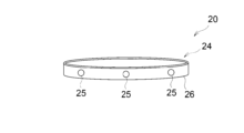
- the contact acting device 24 has a plurality of force-generating drivers 25 and a mounting 26 that holds the plurality of drivers 25 and is worn on the torso of a person.
- the driver 25 is a device that generates a force that is tactilely transmitted to the person P1.
- the driving body 25 may be a DC motor, a piezoelectric element, an artificial muscle, a pneumatic balloon, or the like, and is not particularly limited.
- the mounting tool 26 is a belt, and holds a plurality of driving bodies 25 spaced apart in the longitudinal direction thereof.
- FIG. 4A is a bird's-eye view of the contact action device 24, and FIG. 4B is a plan view of the contact action device 24.
- FIG. 4A and 4B when the belts that are the attachments 26 are connected in a circle, a plurality of driving bodies 25 are held at intervals of 60 degrees in the circumferential direction of the attachments 26 .
- the mounting device 26 also holds the communication unit 21, the internal sensor 22, and the drive control unit 23 as a package.
- the internal sensor 22 comprises an IMU and/or a gyro sensor.
- the eye tracker is separated from the wearer 26 and electrically connected to the communication unit 21 .
- the contact action device 24 When the contact action device 24 is worn on the torso of the person P1, a plurality of drivers 25 are arranged around the torso. As a result, the contact action device 24 determines the generation position of the force tactilely transmitted to the person P1 according to the drive signal, specifically according to the orientation of the moving body 40 with respect to the person P1 estimated by the estimation device 10. can be changed.
- the contact action device 24 is not limited to being worn on the torso of the person P1.
- the contact action device 24 may be configured to be wrapped around the arm or leg of the person P1, be attached to the body of the person P1 in the form of a stretchable sheet, or be held by the hand of the person P1. etc.
- the external sensor 30 In this embodiment, a plurality of external sensors 30 are arranged above the stage as shown in FIG.
- the external sensor 30 tracks the person P1 and the moving object 40 on the stage to identify the positions of the person P1 and the moving object 40 . Then, the external sensor 30 transmits the positional information of the specified person P1 and the positional information of the moving object 40 to the estimation device 10 .
- the external sensor 30 in this embodiment is UWB (Ultra Wide Band).
- the external sensor 30 may be an RGB camera, an RGBD camera, a motion capture system, or the like, and is not particularly limited.
- the estimating device 10 receives the moving speed information, acceleration information, etc. of the person P1 from the internal world sensor 22 of the notification device 20, and also receives information about the positions of the person P1 and the moving body 40 from the external world sensor 30. Then, the estimation device 10 estimates the state of the person P1 using the subject state estimation unit 12 .
- the state of the person P1 includes position information, moving speed information, posture information, face orientation information, and the like of the person P1.
- the information on the estimated state of the person P1 is provided to the positional relationship estimation unit 14, and the positional relationship estimation unit 14 registers the information on the state of the person P1 on the map data (step S51).
- the estimation device 10 receives information about the positions of the person P1 and the moving body 40 from the external sensor 30, and estimates the state of the moving body 40 by the moving body state estimation unit 13.
- the state of the moving body 40 includes position information and moving speed information of the moving body 40 .
- the information on the estimated state of the moving object 40 is provided to the positional relationship estimating unit 14, and the positional relationship estimating unit 14 registers the information on the state of the moving object 40 on the map data (step S52).
- the positional relationship estimation unit 14 estimates the positional relationship between the two based on the information on the state of the person P1 and the information on the state of the moving body 40.
- the positional relationship estimation unit 14 integrates the information on the state of the person P1 and the information on the state of the moving body 40 on the map data. Then, the positional relationship estimation unit 14 estimates the positional relationship between the person P1 and the moving body 40 on the map data. Then, the positional relationship estimation unit 14 provides the estimated positional relationship to the notification determination planning unit 15, and the notification determination planning unit 15 determines whether the provided positional relationship satisfies the notification conditions (step S53). .
- the notification determination planning unit 15 determines that it is necessary to notify the person P1 of the positional relationship.
- a command signal to be transmitted is generated (step S54).
- the command signal is changed according to the positional relationship information in this embodiment.
- the process returns to step S51 and the estimation process is performed.
- the notification determination planning unit 15 transmits the command signal to the notification device 20 (step S55). Then, the notification device 20 tactilely notifies the person P1 of the positional relationship between the person P1 and the moving body 40 in response to the command signal.
- the command signal is provided to the touch action device 24 after being converted into a drive signal. In this embodiment, by changing the command signal according to the positional relationship information, the contact action device 24 changes the form of tactile notification and/or the notification position according to the positional relationship. After that, the process returns to step S51, and the estimation process is performed.
- Specific mode of notification Specific modes 1 to 4 when notifying or not notifying the person P1 of the positional relationship between the person P1 and the mobile body 40 by the contact action device 24 will be described below.
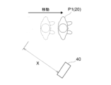
- FIG. 6 shows a state in which the moving body 40 moves autonomously along a predetermined route with a predetermined speed pattern by program running. Further, in this example, the estimated current distance between the person P1 and the moving object 40 is a predetermined value as the notification condition for the estimation device 10 to notify the person P1 of the positional relationship between the person P1 and the moving object 40.
- FIG. 6 shows a state in which the current distance X between the person P1 and the mobile object 40 has become equal to or less than a predetermined value.
- FIG. 6 shows the state of the estimation process started at time t, where time t indicates the reference time.
- Position (a, b) indicates the position information of the moving object 40 at present (reference time t).
- a position (c, d) indicates the position information of the person P1 at present (reference time t).
- the estimated distance X between the person P1 and the moving object 40 at the present (reference time t) is equal to or less than a predetermined value.
- the distance X is determined by the positional relationship estimating unit 14 based on the position information of the moving body 40 specifying the position (a, b) from the moving body state estimating unit 13 and the position (c, d) from the subject state estimating unit 12.
- a time t+dt indicates a time after a predetermined time dt from the reference time t.
- a position (a', b') indicates position information (future position of the mobile body) of the mobile body 40 after a predetermined time dt from the reference time t.
- the position (a', b') is estimated by the positional relationship estimation unit 14 based on the moving speed information of the person P1 and the moving body 40.
- FIG. As a result, information on the orientation of the moving body 40 with respect to the person P1 after the predetermined time dt and information on the distance between the person P1 and the moving body 40 after the predetermined time dt are also estimated.
- the notification determination planning unit 15 changes the orientation of the mobile body 40 with respect to the person P1 at the reference time t of the estimation start to the direction of the mobile body 40 with respect to the person P1 after a predetermined time dt.
- a command signal containing information for changing the position of the tactile notification is generated. Further, this command signal includes information designating that the force to be transmitted to the person P1 is gradually reduced as the position of the tactile notification is changed.
- the orientation of the moving body 40 with respect to the person P1 at the start of estimation is forward, and the orientation of the moving body 40 with respect to the person P1 after the predetermined time dt is left front.
- the moving body state estimating unit 13 uses the position information of the moving body 40 based on the information or data received from the external sensor 30 and the pattern information of the program running to obtain the moving speed information specified in the pattern information.
- the moving speed information of the moving object 40 is estimated, and the future position of left front is estimated using this estimated moving speed information.
- Rp in FIG. 6 indicates a program running route.
- the command signal information is specified to change the position at which the tactile notification is performed from the front side to the left side of the torso over time, and the tactile notification from the front side to the left side is specified.
- Information designating that the force to be transmitted to the person P1 is gradually reduced is designated along with the change of the position for performing the exercise.
- the notification device 20 that has received the command signal as described above generates a force that is tactilely transmitted to the person P1 from the front side to the left side of the torso over time, and generates a force from the front side to the left side of the torso.
- a drive signal is generated to drive the contact acting device 24 such that the force imparted to the person P1 becomes progressively smaller as the position changes.
- the contact action device 24 provided with such a driving signal sequentially drives a plurality of driving bodies 25 counterclockwise from the front driving body 25 among the plurality of driving bodies 25 around the torso.
- the driving body 25 is controlled so that the force generated by the driving body 25 gradually decreases counterclockwise.
- V1, V2, and V3 in FIG. 6 indicate the degree of force at the time of notification, and the larger the size, the stronger the force.
- V1 to V3 the person P1 receives a force flowing from the front side of the torso to the left side, and this force gradually decreases.
- the person P1 who has received such a notification becomes more likely to intuitively recognize the direction in which the moving object 40 is approaching him and the moving object 40 is going to the left with respect to him.
- FIG. 7 shows a mobile object 40 moving according to remote control by a user.
- the notification condition for estimating device 10 to notify person P1 of the positional relationship between person P1 and moving object 40 the estimated current distance between person P1 and moving object 40 is less than or equal to a predetermined value.
- the notification determination planning unit 15 generates a command signal and transmits it to the notification device 20 .
- the notification device 20 then generates a driving signal and supplies it to the contact acting device 24 to drive the contact acting device 24 .
- FIG. 8 shows a mobile object 40 moving according to remote control by a user.
- the notification condition for estimating device 10 to notify person P1 of the positional relationship between person P1 and moving object 40 the estimated current distance between person P1 and moving object 40 is less than or equal to a predetermined value.
- the notification determination planning unit 15 generates a command signal and transmits it to the notification device 20 .
- the notification device 20 then generates a driving signal and supplies it to the contact acting device 24 to drive the contact acting device 24 .
- notification is provided on the condition that it is estimated that the person P1 is moving at a speed equal to or higher than a predetermined speed.
- the person P1 is standing still while the mobile object 40 is approaching, there is a high possibility that the person P1 recognizes the existence of the mobile object 40 . In this case, if the notification is given, the person P1 may feel annoyed. Considering such a point, notification is not performed when it is estimated that the person P1 is not moving. This enables user-friendly notification.
- FIG. 10 shows a mobile object 40 moving according to remote control by a user. Further, in this example, the estimated current distance between the person P1 and the moving object 40 is a predetermined value as the notification condition for the estimation device 10 to notify the person P1 of the positional relationship between the person P1 and the moving object 40.
- FIG. 10 shows a state in which the current distance X between the person P1 and the mobile object 40 has become equal to or less than a predetermined value.
- FIG. 10 shows the state of the estimation process started at time t, where time t indicates the reference time.
- Position (a, b) indicates the position information of the moving object 40 at present (reference time t).
- a position (c, d) indicates the position information of the person P1 at present (reference time t).
- the estimated distance X between the person P1 and the mobile object 40 at the present (reference time t) is equal to or less than a predetermined value.
- the distance X is determined by the positional relationship estimating unit 14 based on the position information of the moving body 40 specifying the position (a, b) from the moving body state estimating unit 13 and the position (c, d) from the subject state estimating unit 12.
- a time t+dt indicates a time after a predetermined time dt from the reference time t.
- a position (a', b') indicates position information (future position of the mobile body) of the mobile body 40 after a predetermined time dt from the reference time t.
- the position (a', b') is specified by the positional relationship estimation unit 14 based on the moving speed information of the person P1 and the moving body 40.
- FIG. As a result, information on the orientation of the moving body 40 with respect to the person P1 after the predetermined time dt and information on the distance between the person P1 and the moving body 40 after the predetermined time are also estimated.
- the notification determination planning unit 15 changes the orientation of the mobile body 40 with respect to the person P1 at the reference time t of the estimation start to the direction of the mobile body 40 with respect to the person P1 after a predetermined time dt.
- a command signal containing information for changing the position of the tactile notification is generated. Further, this command signal includes information designating that the force to be transmitted to the person P1 is gradually reduced as the position of the tactile notification is changed.
- the orientation of the moving body 40 with respect to the person P1 at the start of estimation is expected to be forward, and the orientation of the moving body 40 with respect to the person P1 after a predetermined time dt is expected to be left front.
- a prediction is made by the moving body state estimation unit 13 analyzing the moving pattern of the moving body 40 based on the information or data received from the external sensor 30 and estimating the moving speed information.
- the angle ⁇ , the moving speed at the angle ⁇ of 1.2 mps, and the angular speed of 0.013° are estimated as the moving speed information.
- the angle ⁇ and the moving speed of 1.2 mps are estimated from the speed information of the XYZ axes.
- the position (a′, b′) after a predetermined time dt from the reference time t is calculated by the positional relationship estimating unit 14 as the moving speed information of the moving body 40, which is the angle ⁇ , and the moving speed 1 at the angle ⁇ . .2 mps and an angular velocity of 0.013°.
- the command signal information is specified to change the position at which the tactile notification is performed from the front side to the left side of the torso over time, and the tactile notification from the front side to the left side is specified.
- Information is designated to designate that the force to be transmitted to the person P1 is gradually reduced as the position for performing the exercise is changed.
- the notification device 20 that has received the command signal as described above generates a force that is tactilely transmitted to the person P1 from the front side to the left side of the torso over time, and generates a force from the front side to the left side of the torso.
- a drive signal is generated to drive the contact acting device 24 such that the force imparted to the person P1 becomes progressively smaller as the position changes.
- the contact action device 24 provided with such a driving signal sequentially drives a plurality of driving bodies 25 counterclockwise from the front driving body 25 among the plurality of driving bodies 25 around the torso.
- the driving body 25 is controlled so that the force generated by the driving body 25 gradually decreases counterclockwise.
- the information processing system S1 includes the estimating device 10, which is an estimating unit that estimates the positional relationship between the person P1 and the moving object 40, based on the state of the person P1 and the state of the moving object 40. and a notification device 20 which is a notification unit that is worn on the body of the person P1 and tactilely notifies the person P1 of the positional relationship estimated by the estimation device 10 .
- the positional relationship estimated by the estimation device 10 can be tactilely notified to the person P1.
- the information processing system S1 is applied in a situation where the performance of the person P1 is photographed from the mobile body 40.
- FIG. In such a situation, the lights fly in different directions, and the performance and the cheering of the audience can be very loud.
- the sense of the person P1 is restricted.
- the presence of the moving body 40 is tactilely notified to the person P1, so that the person P1 can reliably recognize the presence of the moving body 40.
- the tactile notification does not interfere with the playing or directing during the performance, so it is possible to suppress the influence on the performance, which is also beneficial in this respect.
- FIG. 11 is a diagram showing an information processing system S2 according to the second embodiment and its application status.
- FIG. 11 shows a situation in which a person P2, who is a security guard, is guiding a vehicle in a parking lot.
- the information processing system S2 notifies the person P2 of the positional relationship between the person P2 and the mobile object 40 . As a result, contact between the person P2 and the mobile object 40 is avoided and attention is drawn to the person P2.
- This embodiment differs from the first embodiment in that the external sensor 30 is an RGB camera.
- the information processing system S2 can estimate the positions of the person P2 and the moving object 40 with high accuracy.
- the notification conditions for notifying the person P2 of the positional relationship between the person P2 and the moving object 40 are that the estimated current distance between the person P2 and the moving object 40 is less than or equal to a predetermined value, and that the visual field of the person P2 is As an example, a condition is set that the moving object 40 is not inside. As a result, for example, it is possible to notify the person P2 of the existence of the moving object 40A located behind the person P2 without notifying the person P2 of the existence of the moving object 40B located in front of the person P2.
- the moving speed information of the moving body 40 may be estimated based on the position information of the moving body 40 acquired by the external sensor 30 . If the moving object 40 is a manned vehicle and has a predetermined travel route such as a parking lot, the moving speed information of the moving object 40 can be estimated relatively easily with high accuracy. Based on the moving speed information of the moving body 40 estimated in this way, information (prediction information) about the orientation of the moving body 40 with respect to the person P2 after a predetermined time from the reference time, and the direction of the moving body 40 with respect to the person P2 and the moving body 40 after a predetermined time. information (prediction information) on the distance between and may be estimated. And the notification mode may be changed by using these prediction information.
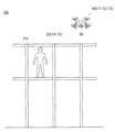
- FIG. 12 is a diagram showing an information processing system S3 according to the third embodiment and its application status.
- FIG. 12 shows a situation in which a worker P3 is working in front of the belt conveyor BC in the factory. Moreover, FIG. 12 shows a state in which a moving body 40 that moves autonomously conveys parts.
- the information processing system S3 notifies the person P3 of the positional relationship between the person P3 and the mobile object 40 . As a result, contact between the person P3 and the moving body 40 is avoided and attention is drawn to the person P3.
- the estimated current distance between the person P3 and the moving object 40 is a predetermined value or less, and It is desirable to set a condition that the moving object 40 is not in the field of view of P3 and that the person P3 is in a distracted state.
- the external sensor 30 is an RGB camera.
- an eye tracker is included in the internal sensor 22 of the notification device 20, and the person P3 is wearing the eye tracker. Thereby, it is detected whether or not the person P3 is in a distracted state.
- the moving speed information of the moving object 40 can be estimated from the moving speed information specified in the pattern information using the position information of the moving object 40 acquired by the external sensor 30 and the pattern information of the program running.
- the moving body 40 used in the factory generally performs programmed travel except for emergency avoidance and emergency stop. Therefore, it is desirable to efficiently estimate the moving speed information of the moving body 40 by using the program running pattern information.
- information (prediction information) about the orientation of the moving body 40 with respect to the person P3 after a predetermined time from the reference time information (prediction information) on the distance between and may be estimated. And the notification mode may be changed by using these prediction information.
- FIG. 13 is a diagram showing an information processing system S4 according to the fourth embodiment and its application status.
- a moving body 40 which is an unmanned flying object (drone)
- a worker P4 is also located at high places.
- the information processing system S4 notifies the person P4 of the positional relationship between the person P4 and the drone as the mobile object 40 .
- contact between the person P4 and the moving object 40 is avoided and attention is drawn to the person P4.
- the external sensor 30 is integrated with the moving body 40 .
- the external sensor 30 is configured by, for example, an RGBD camera provided on the moving body 40 .
- the functions of the estimation device 10 shown in FIG. Specifically, the communication unit 11 , the subject state estimation unit 12 and the moving body state estimation unit 13 are provided in the moving body 40 .
- the positional relationship estimation unit 14 and the notification determination planning unit 15 are provided in the notification device 20 .
- the notification device 20 is attached to the helmet worn by the person P4.
- the subject state estimation unit 12 provided in the moving body 40 estimates the position of the person P4 based on information from the external sensor 30, which is an RGBD camera. Then, the subject state estimation unit 12 transmits information on the position of the person P4 to the notification device 20 via the communication unit 11 .
- the mobile body state estimator 13 may be composed of any one of IMU, GPS, and 3DLidar, or a combination of two or more. The moving object state estimating unit 13 transmits the estimated position information, moving speed information, etc. of the moving object 40 to the notification device 20 via the communication unit 11 .
- the moving speed information of the moving object 40 which is a drone, can be estimated from the moving speed information specified in the pattern information using the position information of the moving object 40 acquired by the external sensor 30 and the pattern information of the program operation. Inspection drones generally fly in programmed operation, except during emergency avoidance and emergency shutdown. Therefore, it is desirable to efficiently estimate the moving speed information of the moving body 40 by using the pattern information of the program operation. Then, based on the moving speed information of the moving object 40 estimated in this way, information (prediction information) about the orientation of the moving object 40 with respect to the person P4 after a predetermined time from the reference time, and movement information with the person P4 after a predetermined time. information (prediction information) on the distance to the body 40 may be estimated. And the notification mode may be changed by using these prediction information.
- the condition that the person P4 is moving may be set as the notification condition for notifying the person P4 of the positional relationship between the person P4 and the moving body 40.
- FIG. 14 is a diagram showing an information processing system S5 according to the fifth embodiment and its application status.
- FIG. 14 shows that a person P5 is driving a vehicle V, and a moving object 40, which is another vehicle, approaches the vehicle that the person P5 is driving.
- the information processing system S5 notifies the person P5 of the positional relationship between the person P5 and the vehicle as the mobile object 40 .
- contact between the vehicle V of the person P5 and the moving body 40 is avoided and the attention of the person P5 is called.
- the vehicle V is provided with the estimation device 10, the notification device 20, and the external sensor 30 shown in FIG.
- the external sensor 30 may be a Lidar provided on the vehicle V, an RGBD camera, a GPS, or the like.
- the internal sensor 22 provided in the notification device 20 may be a biosensor or an eye tracker.
- the touch action device 24 in the notification device 20 is provided, for example, on a ring-shaped handle operated by the person P5.
- the contact action device 24 may comprise a plurality of drivers 25 spaced circumferentially around the annular handle.
- the moving speed information of the mobile body 40 can be estimated based on the position information of the mobile body 40 acquired by the external sensor 30 . Based on the estimated moving speed information of the moving body 40, the direction information (prediction information) of the moving body 40 with respect to the person P5 after a predetermined time from the reference time, and the distance between the person P5 and the moving body 40 after a predetermined time distance information (prediction information) and can be estimated. At this time, the estimation accuracy is improved by taking into consideration the position information and the moving speed information of the vehicle V driven by the person P5.
- the estimated current distance between the person P5 and the moving object 40 is a predetermined value or less
- the person A condition may be set that the moving object 40 is not in the field of view of P5.
- FIG. 15 is a diagram showing an information processing system S6 according to the sixth embodiment and its application status.
- FIG. 15 shows a situation in which a worker P6 is working in front of the belt conveyor BC in the factory. Moreover, FIG. 15 shows a state in which a plurality of moving bodies 40 that move autonomously are moving to transport parts and the like.
- the information processing system S6 notifies the person P6 of the positional relationship between the person P6 and the mobile object 40 . As a result, contact between the person P6 and the mobile object 40 is avoided and attention is drawn to the person P6.
- the notification condition for notifying the person P6 of the positional relationship between the person P6 and the moving object 40 the condition that the distance between the person P6 and the moving object 40 after a predetermined time is equal to or less than a predetermined value is set. be done.
- the position of the moving body 40 after a predetermined time is indicated by a dashed line.
- the notification device 20 notifies the person P6 of the presence of the mobile object 40-2.
- the notification may be performed by generating a force applied to the person by the notification device 20 at a position corresponding to the orientation of the moving body 40-2 with respect to the person P6. Furthermore, the position where the force is generated may be changed so that the moving direction of the moving body 40-2 can be grasped.
- the moving object 40 located in an area where there is no risk of contact with the person P6 is excluded from the targets of notification.
- the moving body 40-4 located on the opposite side of the belt conveyor BC to the side on which the person P6 is located has no risk of coming into contact with the person P6. Therefore, the mobile unit 40-4 is excluded from the notification targets.
- Whether or not to exclude is determined by identifying a hatched non-notification area R and determining whether or not a mobile object exists in the non-notification area R.
- the non-notification area R may be identified by the estimating device 10 based on information from the external sensor 30, map data held inside, or the like.
- the moving speed information of the moving body 40 can be estimated from the moving speed information specified in the pattern information using the position information of the moving body 40 acquired by the external sensor 30 and the pattern information of the program running.
- the moving body 40 used in the factory generally performs program travel except for emergency avoidance and emergency stop. Therefore, it is desirable to efficiently estimate the moving speed information of the moving body 40 by using the program running pattern information.
- information (prediction information) about the orientation of the moving body 40 with respect to the person P6 after a predetermined time from the reference time, and the direction of the person P6 and the moving body 40 after a predetermined time.
- FIG. 16 shows an example of the hardware configuration of the estimation device 10 or the notification device 20.
- the estimation device 10 or the notification device 20 is configured by a computer device 400 .
- the computer device 400 includes a CPU 401, an input interface 402, an external interface 403, a communication device 404, a main storage device 405, and an external storage device 406, which are interconnected by a bus. At least one of these elements may not be included in the estimation device 10 or the notification device 20 .
- a CPU (Central Processing Unit) 401 executes computer programs on a main memory device 405 .
- a computer program is a program that implements the above functional configurations of the estimation device 10 or the notification device 20 .
- a computer program may be realized by a combination of a plurality of programs and scripts instead of a single program. Each functional configuration is realized by the CPU 401 executing a computer program.
- the input interface 402 is a circuit for inputting operation signals from input devices such as a keyboard, mouse, and touch panel to the estimation device 10 or notification device 20 .
- the external interface 403 displays, for example, data stored in the estimation device 10 or the notification device 20 or data calculated by the estimation device 10 or the notification device 20 on the display device.
- the external interface 403 may be connected to, for example, an LCD (liquid crystal display), an organic electroluminescence display, a CRT (cathode-ray tube), or a PDP (plasma display).
- the communication device 404 is a circuit for the estimation device 10 or the notification device 20 to communicate with an external device wirelessly or by wire. Data used by the estimation device 10 or the notification device 20 can be input from an external device via the communication device 404 . Communication device 404 includes an antenna. Data input from an external device can be stored in the main storage device 405 or the external storage device 406 . The communication units 11 and 21 described above may be constructed by the communication device 404 .
- the main storage device 405 stores computer programs, data necessary for executing the computer programs, data generated by executing the computer programs, and the like.
- a computer program is developed and executed on the main memory device 405 .
- the main storage device 405 is, for example, RAM, DRAM, or SRAM, but is not limited thereto.
- a storage unit for information and data in the estimation device 10 or the notification device 20 may be constructed on the main storage device 405 .
- the external storage device 406 stores computer programs, data necessary for executing the computer programs, data generated by executing the computer programs, and the like. These computer programs and data are read into the main memory device 405 when the computer programs are executed.
- the external storage device 406 is, for example, a hard disk, an optical disk, a flash memory, and a magnetic tape, but is not limited to these.
- the computer program may be pre-installed in the computer device 400, or may be stored in a storage medium such as a CD-ROM.
- the computer program may also be uploaded on the Internet.
- the computer device 400 may be configured by a single device, or may be configured as a system composed of a plurality of interconnected computer devices.
- this disclosure can also take the following configurations.
- an estimating unit that estimates the positional relationship between the person and the moving object based on the state of the person and the state of the moving object; an information processing system comprising: a notification unit that is worn on the person's body or comes into contact with the person's body and that notifies the person of the positional relationship in a tactile sense.
- a notification unit that is worn on the person's body or comes into contact with the person's body and that notifies the person of the positional relationship in a tactile sense.
- the notification unit changes a position at which tactile notification is performed according to the positional relationship.
- the notification unit changes a form of tactile notification according to the positional relationship.
- the information processing system according to any one of items 1 to 3, wherein the notification unit changes a form of tactile notification according to the state of the person.
- the estimating unit uses, as the positional relationship, at least one of information on the orientation of the moving body with respect to the person after a predetermined time from a reference point of time to start estimation and information on the distance between the person and the moving body. 5.
- the information processing system according to any one of items 1 to 4, specified.
- Item 6 Item 6.
- the information processing system according to item 5, wherein the positional relationship also includes at least one of information on the orientation of the moving body with respect to the person at the reference time and information on the distance between the person and the moving body.
- the positional relationship includes information on the orientation of the mobile body with respect to the person at the reference time and information on the orientation of the mobile body with respect to the person after a predetermined time from the reference time,
- the notification unit changes a position for tactile notification in accordance with a change in the orientation of the moving body with respect to the person at the reference time to the orientation of the moving body with respect to the person after the predetermined time.
- Item 8 Item 8. The information processing system according to item 7, wherein the notification unit reduces a force conveyed to the person in the tactile notification as a position of the tactile notification is changed.
- the positional relationship includes information on the distance between the person and the moving object at the reference time and information on the distance between the person and the moving object after a predetermined time from the reference time, 8.
- [Item 10] 10 10.
- the information processing system determines that notification by the notification unit is necessary when determining that the moving object is not in the field of view of the person.
- a notification unit attached to or in contact with a person's body The information processing device, wherein the notification unit tactilely notifies the person of a positional relationship between the person and the moving object estimated based on the state of the person and the state of the moving object.
- the notification unit tactilely notifies the person of a positional relationship between the person and the moving object estimated based on the state of the person and the state of the moving object.
- S1, S2, S3, S4, S5, S6... Information processing system 10 ... Estimating device 11... Communication unit 12... Subject state estimating unit 13... Moving body state estimating unit 14... Positional relationship estimating unit 15... Notification judgment planning unit 20 Notification device 21 Communication unit 22 Internal sensor 23 Drive control unit 24 Contact action device 25 Driver 26 Mounting device 30 External sensor 40 Mobile object 41 Photographing device 50 Communication networks P1 to P6 Person 400...Computer device 401...CPU 402... Input interface 403... External interface 404... Communication device 405... Main storage device 406... External storage device 10... Estimating device 11... Communication unit 12... Subject state estimating unit 13... Moving body state estimating unit 14... Positional relationship estimating unit 15... Notification judgment planning unit 20 Notification device 21 Communication unit 22 Internal sensor 23 Drive control unit 24 Contact action device 25 Driver 26 Mounting device 30 External sensor 40 Mobile object 41 Photographing device 50 Communication networks P1 to P6 Person 400...Computer device 401...CPU 402... Input interface 403... External interface 404... Communication device 405... Main storage device 406
Landscapes
- Engineering & Computer Science (AREA)
- General Engineering & Computer Science (AREA)
- Physics & Mathematics (AREA)
- General Physics & Mathematics (AREA)
- Theoretical Computer Science (AREA)
- Human Computer Interaction (AREA)
- Aviation & Aerospace Engineering (AREA)
- Radar, Positioning & Navigation (AREA)
- Remote Sensing (AREA)
- Automation & Control Theory (AREA)
- Traffic Control Systems (AREA)
Abstract
[課題]人及び移動体が置かれている状況や、人の感覚に制約がある場合であっても、移動体の存在を人に確実に認識させることが可能な情報処理システムの提供。 [解決手段]一実施形態に係る情報処理システムS1は、人の状態と移動体の状態とに基づいて、人と移動体との位置関係を推定する推定装置10と、人の身体に装着されるか又は前記人の身体と接触し、推定装置10が推定する位置関係を触覚的に人に通知する通知装置20と、を備える。
Description
本開示は、情報処理システム、情報処理方法、情報処理装置及びコンピュータプログラムに関する。
近年、様々な移動体が種々の産業分野で利用されている。今後の活用が特に期待される移動体として、自律移動型の無人車両や、無人航空機(ドローン)などが挙げられる。これら無人車両や無人航空機は、撮影、計測、災害救助、輸送物流などの用途で既に用いられている。
移動体が移動している際には、周囲の人に移動体の存在を通知することが望まれる場合がある。この要望に関連する技術として、移動体と周囲の物体との位置関係に応じて、移動体上の発光装置を発光させる技術がある。この技術では、光に代えて、音が利用されてもよい。
しかしながら、光や音は、移動体の存在を確実に人に認識させることができない場合がある。具体的なケースとして、例えば、人の視野に移動体が入っていない状況、光が様々な方向に飛び交う状況、大音量で音楽が流れる状況などが挙げられる。
より具体的には、例えばアーティストのパフォーマンスを移動体で撮影している際に、移動体の存在をアーティストに光や音で通知する状況が挙げられる。この場合、アーティストは移動体を常に見ているわけではない。また、様々な方向に光が飛び交い、演奏や観客の歓声が大音量になり得る。
以上のような状況下であると、光や音は、アーティストに移動体の存在を確実に認識させることができない。また、パフォーマンス中の演奏や演出と無関係な光や音はパフォーマンスを阻害し得るため、必ずしも望ましくない。
本開示は上記事情を考慮してなされたものであり、人及び移動体が置かれている状況や、人の感覚に制約がある場合であっても、移動体の存在を人に確実に認識させることが可能な情報処理システム、情報処理方法、情報処理装置及びコンピュータプログラムを提供する。
本開示の情報処理システムは、人の状態と移動体の状態とに基づいて、前記人と前記移動体との位置関係を推定する推定部と、前記人の身体に装着されるか又は前記人の身体と接触し、前記位置関係を触覚的に前記人に通知する通知部と、を備える。
本開示の情報処理方法は、人の状態と移動体の状態とに基づいて、前記人と前記移動体との位置関係を推定するステップと、前記人の身体に装着されるか又は前記人の身体と接触するデバイスを介して、前記位置関係を触覚的に前記人に通知するステップと、を備える。
本開示の情報処理装置は、人の身体に装着されるか又は人の身体と接触する通知部を備え、前記通知部は、前記人の状態と移動体の状態とに基づいて推定される前記人と前記移動体との位置関係を触覚的に前記人に通知する。
本開示のコンピュータプログラムは、人の状態と移動体の状態とに基づいて、前記人と前記移動体との位置関係を推定するステップと、前記人の身体に装着されるか又は前記人の身体と接触するデバイスを介して、前記位置関係を触覚的に前記人に通知するステップと、をコンピュータに実行させる。
以下、図面を参照して本開示の実施形態について説明する。本開示において示される1以上の実施形態において、各実施形態が含む要素を互いに組み合わせることができ、かつ、当該組み合わせられた結果物も本開示が示す実施形態の一部をなす。
<第1実施形態>
図1は、第1実施形態に係る情報処理システムS1及びその適用状況を示す図である。図2は、情報処理システムS1の構成を概略的に示す図である。まず、情報処理システムS1の概略構成について図1及び図2を参照しつつ説明する。
図1は、第1実施形態に係る情報処理システムS1及びその適用状況を示す図である。図2は、情報処理システムS1の構成を概略的に示す図である。まず、情報処理システムS1の概略構成について図1及び図2を参照しつつ説明する。
(情報処理システム)
図1は、ステージ上でパフォーマンスを行う人P1を移動体40から撮影装置41で撮影している状況を示している。移動体40は、移動することにより種々の角度から人P1を撮影することを予定している。本実施形態に係る情報処理システムS1は、パフォーマンスを行う人P1を移動体40から撮影する状況において適用され、人P1と移動体40との位置関係を人P1に通知する処理を行う。これにより、人P1と移動体40との接触の回避及び人P1の効果的な撮影の実現を図る。
図1は、ステージ上でパフォーマンスを行う人P1を移動体40から撮影装置41で撮影している状況を示している。移動体40は、移動することにより種々の角度から人P1を撮影することを予定している。本実施形態に係る情報処理システムS1は、パフォーマンスを行う人P1を移動体40から撮影する状況において適用され、人P1と移動体40との位置関係を人P1に通知する処理を行う。これにより、人P1と移動体40との接触の回避及び人P1の効果的な撮影の実現を図る。
情報処理システムS1は、推定装置10と、通知装置20と、外界センサ30とを備える。推定装置10は、人P1の身体に装着された通知装置20が取得する人P1の情報と、外界センサ30が取得する人P1及び移動体40の情報とに基づいて、人P1と移動体40との位置関係を推定する。通知装置20は、一例として人P1の胴部に装着されている。通知装置20は、推定装置10から提供される指令信号に応じて、人P1と移動体40との位置関係を人P1に触覚的に通知する。
外界センサ30は、少なくともステージ上の人P1の位置及び移動体40の位置を特定する。外界センサ30が特定する情報は、推定装置10に提供され、人P1と移動体40との位置関係を推定する際に用いられる。
図1に示される移動体40は無人車両である。移動体40は、予め定められた経路を予め定められた速度パターンで自律的に移動してもよい。すなわち、移動体40は、プログラム走行にて移動してもよい。また、移動体40は、ユーザによる遠隔操作に応じて移動してもよい。移動体40はドローンなどでもよく、特に限定されない。また、移動体40は有人の移動体でもよい。
図2に示すように、推定装置10、通知装置20及び外界センサ30は、通信ネットワーク50を介して接続される。このうちの推定装置10と通知装置20とは双方向に通信可能である。通信ネットワーク50は、インターネットなどのワイドエリアネットワークでも、無線LAN(Local Area Network)又はイーサネット(登録商標)などのローカエルネットワークでもよい。通信ネットワーク50は、5Gに準拠した通信網であることが望ましい。
以下、情報処理システムS1を構成する推定装置10、通知装置20及び外界センサ30について説明する。なお、推定装置10の少なくとも一部の構成又は機能は、本開示に係る情報処理システムにおける推定部に対応する。通知装置20の少なくとも一部の構成又は機能は、本開示に係る情報処理システムにおける通知部に対応する。
(推定装置)
図3は、推定装置10及び通知装置20それぞれのブロック図を示す。図3に示すように、推定装置10は、通信部11と、対象者状態推定部12と、移動体状態推定部13と、位置関係推定部14と、通知判断計画部15とを有する。
図3は、推定装置10及び通知装置20それぞれのブロック図を示す。図3に示すように、推定装置10は、通信部11と、対象者状態推定部12と、移動体状態推定部13と、位置関係推定部14と、通知判断計画部15とを有する。
通信部11は、通知装置20及び外界センサ30と無線通信を行う。通信部11は、通知装置20とは情報又はデータの送受信を行い、外界センサ30からは情報又はデータを受信する。通信部11は、例えば一定のサンプル時間間隔で通知装置20及び外界センサ30から情報又はデータを受信する。通信部11は、通知装置20及び外界センサ30から受信した情報又はデータを対象者状態推定部12に提供する。また、通信部11は、外界センサ30から受信した情報又はデータを移動体状態推定部13に提供する。
また、通信部11は、指令信号を通知装置20に送信する。指令信号は、通知装置20及び外界センサ30からの情報又はデータに基づいて推定される人P1と移動体40との位置関係を通知装置20で人P1に通知する際に生成される。指令信号は、詳細は後述するが、通知判断計画部15によって生成される。
通信部11が採用する無線通信の方式は任意でよい。一例として、IEEE802.11規格、IEEE802.15.1規格、その他の規格によるものでもよい。無線通信に使用する周波数帯域は、例えば2.4GHz帯、5GHz帯、又はその他の周波数帯域である。
対象者状態推定部12は、通知装置20及び外界センサ30から受信した情報又はデータに基づき、人P1の状態を推定する。人P1の状態は、人P1の位置情報、移動速度情報、姿勢情報、顔の向きの情報などを含む。位置情報は、緯度と経度でもよい。或いは、位置情報は、例えば、(X,Y,Z)=(7.3m、4.1m、0m)のような、所定の基準の位置を原点とした3軸の座標系(XYZの座標系)でもよい。ここで、本実施形態でいうX軸及びY軸は水平面に平行な方向である。移動速度情報は、X軸方向の速度、Y軸方向の速度、及びZ軸方向の速度のうちの少なくともX軸方向の速度及びY軸方向の速度の情報を含む。したがって、移動速度情報は、人P1の移動方向の情報を特定し得る。また、移動速度情報は、X軸周りの角速度、Y軸周りの角速度、及びZ軸周りの角速度のうちの少なくともいずれかを含んでもよい。この場合、人P1の移動方向は、XYZの座標系の速度と角速度とに基づき特定され得る。
本実施形態における対象者状態推定部12は、外界センサ30から受信した情報又はデータに基づき、人P1の位置情報及び移動速度情報を推定し得る。一方で、対象者状態推定部12は、通知装置20から受信した情報又はデータに基づき、人P1の姿勢情報、及び顔の向きの情報を推定し得る。後述するが、通知装置20は内界センサ22を有し、内界センサ22が検出した情報は推定装置10に提供される。対象者状態推定部12は、内界センサ22が検出した情報に基づき、人P1の姿勢情報や顔の向きの情報を推定できる。
ただし、対象者状態推定部12は、人P1の位置情報及び移動速度情報を推定する際に、通知装置20から受信した情報又はデータを考慮してもよい。また、対象者状態推定部12は、人P1の姿勢情報、及び顔の向きの情報を推定する際に、外界センサ30から受信した情報又はデータを考慮してもよい。
移動体状態推定部13は、外界センサ30から受信した情報又はデータに基づき、移動体40の状態を推定する。移動体40の状態は、移動体40の位置情報、移動速度情報を含む。位置情報は、緯度と経度でもよいし、所定の基準の位置を原点とした3軸の座標系(XYZの座標系)でもよい。人P1の場合と同様に、移動体40の移動方向情報は、X軸方向の速度、Y軸方向の速度、及びZ軸方向の速度のうちの少なくともX軸方向の速度及びY軸方向の速度の情報を含む。したがって、移動速度情報は、移動体40の移動方向の情報を特定し得る。また、移動方向情報は、X軸周りの角速度、Y軸周りの角速度、及びZ軸周りの角速度のうちの少なくともいずれかを含んでもよい。この場合、移動体40の移動方向は、XYZの座標系の速度と角速度とに基づき特定され得る。
移動体40は上述したようにプログラム走行にて移動してもよい。この場合、移動体40は、予め定められた経路を予め定められた速度パターンで移動する。移動体40がプログラム走行中である場合、移動体状態推定部13は、外界センサ30から受信した情報又はデータに基づく移動体40の位置情報と、プログラム走行のパターン情報とを用いて、パターン情報に規定された移動速度情報を特定し得る。この場合、移動体状態推定部13は、推定する移動体40の状態として、パターン情報に規定された移動速度情報を採用してもよい。
また、移動体40に内界センサとしてのIMU(Inertial Measurement Unit)、ジャイロセンサ、車輪エンコーダなどを設け、内界センサが検出した情報が推定装置10に送信されてもよい。この場合、移動体状態推定部13は、内界センサの情報に基づき、移動体40の移動方向及び移動速度を推定してもよい。
位置関係推定部14は、対象者状態推定部12が推定した人P1の状態の情報と、移動体状態推定部13が推定した移動体40の状態の情報とを取得する。そして、位置関係推定部14は、人P1の状態の情報と移動体40の状態の情報とに基づき、両者の位置関係を推定する。本実施形態では、位置関係推定部14が人P1の状態の情報と移動体40の状態の情報とを地図データ上に登録し、地図データ上で統合させる。そして、位置関係推定部14は、地図データ上で人P1と移動体40との位置関係を推定する。
本実施形態では、位置関係推定部14が推定する位置関係の情報が、(i)現在の人P1に対する移動体40の向きの情報と、(ii)現在の人P1と移動体40との間の距離の情報と、(iii)所定時間後の人P1に対する移動体40の向きの情報(予測情報)と、(iv)所定時間後の人P1と移動体40との間の距離の情報(予測情報)と、を含む。上述の「現在」は、例えば位置関係推定部14が、移動体状態推定部13が推定した移動体40の状態の情報と、対象者状態推定部12が推定した人P1の状態の情報とを取得して推定を開始する推定開始の基準時点でもよい。この現在が意味する推定開始の基準時点は、(iii)及び(iv)でいう「所定時間」の経過の基準となる。
位置関係の情報には、上記(i)~(iv)に関する情報の他に、現在の人P1の位置情報、移動速度情報、姿勢情報、及び顔の向きの情報と、現在の移動体40の位置情報及び移動速度情報も含まれる。(iii)所定時間後の人P1に対する移動体40の向きの情報(予測情報)及び(iv)所定時間後の人P1と移動体40との間の距離の情報(予測情報)は、人P1の位置情報及び移動速度情報と、移動体40の位置情報及び移動速度情報とに基づいて推定され得る。
なお、本実施形態では、位置関係の情報に上記(i)~(iv)に関する情報が含まれるが、位置関係の情報には、例えば(iii)所定時間後の人P1に対する移動体40の向きの情報(予測情報)と、(iv)所定時間後の人P1と移動体40との間の距離の情報(予測情報)とを含ませなくてもよい。
通知判断計画部15は、位置関係推定部14から提供される人P1と移動体40との位置関係の情報に基づき、この位置関係を、通知装置20を介して人P1に対して通知するための指令信号を生成する。詳しくは、通知判断計画部15は、まず、位置関係の情報に基づき、この位置関係の人P1への通知の要否を判断する。そして、通知判断計画部15は、通知が必要と判断した場合に、通知装置20に送信する指令信号を生成する。本実施形態では、指令信号が位置関係の情報に応じて変更され、これにより、通知装置20で行う通知の態様が置関係の情報に応じて変更される。
通知判断計画部15は、通知の要否の判断を、取得した位置関係の情報が所定の通知条件を充足するか否かで判断する。
通知条件は、推定される現在の人P1と移動体40との間の距離が所定値以下であるという条件でもよい。
通知条件は、推定される現在の人P1と移動体40との間の距離が所定値以下であり、且つ人P1の視野に移動体40が入っていないという条件でもよい。人P1の視野に移動体40が入っているか否かは、例えば人P1の姿勢情報及び/又は顔の向きの情報によって判断できる。
また、通知条件は、推定される現在の人P1と移動体40との間の距離が所定値以下であり、且つ人P1が所定速度以上で移動しているという条件でもよい。
また、通知条件は、人P1の視野に移動体40が入っていない且つ通知必要フラグが設定されているという条件でもよい。通知必要フラグは、任意に設定され得るものであり、設定された場合には、人P1の視野に移動体40が入っていないという条件の成立のみでの通知条件が充足される。このような通知条件は、例えば、人P1と移動体40との距離にかかわらず撮影装置41側に人P1の顔を向かせたい場合に設定されてもよい。
また、通知条件は、人P1が移動しているという条件でもよい。
また、通知条件は、所定時間後の人P1と移動体40との間の距離が所定値以下であるという条件でもよい。
一方で、通知判断計画部15は、人P1の視野に移動体40が入っている場合に、いかなる場合でも通知が不要であると判断してもよい。この場合、通知判断計画部15は、いずれかの通知条件が充足されている場合であっても、通知が不要であると判断してもよい。以上に説明したような通知条件は、例示であり、上述の例に限られない。また、通知条件は、情報処理システムS1のユーザによって任意に一つ又は複数で設定され得る。
そして、通知判断計画部15が生成する指令信号は、本実施形態では、位置関係の情報に応じて変更される。上述したが、通知装置20は、推定装置10からの指令信号に応じて、人P1と移動体40との位置関係を人P1に触覚的に通知する。本実施形態では位置関係の情報に応じて指令信号が変更されることで、通知装置20が触覚的な通知の態様及び/又は通知を行う位置を変更する。
指令信号には、人P1に触覚的に伝える力の指令値(以下、力指令値)の情報、人P1に触覚的に周期的に伝える力の周波数の設定値の情報、人P1に触覚的な通知を行う位置情報などを含めることができる。
通知判断計画部15は、例えば、指令信号における力指令値を人P1と移動体40との間の距離に応じて増減させて指令信号を生成してもよい。この場合、例えば、人P1と移動体40との間の距離が比較的小さい場合に、力指令値が比較的大きい値に設定された指令信号が生成される。このような指令信号を提供された通知装置20は、指令信号に応じて、比較的大きい力で人P1に通知を行うことができる。一方で、移動体40との間の距離が比較的大きい場合には、力指令値が比較的小さい値に設定された指令信号が生成される。このような指令信号を提供された通知装置20は、指令信号に応じて、比較的小さい力で人P1に通知を行うことができる。
また、通知判断計画部15は、指令信号における力の周波数の設定値を人P1と移動体40との間の距離に応じて増減させて指令信号を生成してもよい。この場合、例えば、人P1と移動体40との間の距離が小さい場合に、周波数の設定値が比較的小さい値に設定された指令信号が生成される。このような指令信号を提供された通知装置20は、指令信号に応じて、比較的早い周期で周期的に生じる力で人P1に通知を行うことができる。一方で、移動体40との間の距離が比較的大きい場合には、周波数の設定値が比較的大きい値に設定された指令信号が生成される。このような指令信号を提供された通知装置20は、指令信号に応じて、比較的ゆるやかな周期で周期的に生じる力で人P1に通知を行うことができる。
また、通知判断計画部15は、指令信号における力指令値及び力の周波数の設定値の両方を人P1と移動体40との間の距離に応じて増減させて指令信号を生成してもよい。
また、通知判断計画部15は、人P1に触覚的な通知を行う位置を人P1に対する移動体40の向きに応じて設定して、指令信号を生成してもよい。上述したように本実施形態では、通知装置20が人P1の胴部に装着されている。詳細は後述するが、通知装置20は、人P1の胴部における複数の箇所で触覚的な通知を行うことができる。このような通知装置20が使用される場合、通知判断計画部15は、人P1に対する移動体40の向きに応じて、通知装置20における通知の発生位置を指定して指令信号を生成してもよい。
具体的には、通知判断計画部15は、人P1に対する移動体40の向きが前方である場合には、胴部の前側を通知の発生位置に指定する指令信号を生成する。また、通知判断計画部15は、人P1に対する移動体40の向きが後方である場合には、胴部の後側を通知の発生位置に指定する指令信号を生成する。このような指令信号を提供された通知装置20は、指令信号に応じて、胴部の前側で力を発生させたり、胴部の後側で力を発生させたりすることができる。なお、通知の発生位置を指定する指令信号には、上述した人P1と移動体40との間の距離に応じて通知の態様を変更させる指令情報が含まれてよい。
また、通知判断計画部15は、指令信号における力指令値を人P1の状態に応じて増減させて指令信号を生成してもよい。或いは、通知判断計画部15は、指令信号における力の周波数の設定値を人P1の状態に応じて増減させて指令信号を生成してもよい。或いは、通知判断計画部15は、指令信号における力指令値及び力の周波数の設定値の両方を人P1の状態に応じて増減させて指令信号を生成してもよい。
具体的には、人P1が所定速度以上で移動している状態の場合に、触覚的に伝える力の指令値が大きく設定される指令信号が生成されてもよい。このような指令信号を提供された通知装置20は、指令信号に応じて、比較的大きい力で人P1に通知を行うことができる。人P1が動いている場合には、触覚的な通知を知覚し難くなる。このような状況を考慮して、上記指令信号が生成されてもよい。
また、通知判断計画部15は、位置関係推定部14が推定する上述の(i)現在の人P1に対する移動体40の向きの情報、(ii)現在の人P1と移動体40との間の距離の情報、(iii)所定時間後の人P1に対する移動体40の向きの情報(予測情報)、及び(iv)所定時間後の人P1と移動体40との間の距離の情報(予測情報)に応じて、異なる通知の態様を実現する指令信号を生成してもよい。
具体的には例えば、通知判断計画部15は、推定開始の基準時点での人P1に対する移動体40の向き(言い換えると、現在の人P1に対する移動体40の向き)から、基準時点から所定時間後の人P1に対する移動体40の向きへの変化に応じて、触覚的な通知を行う位置を変更させる指令情報を含んだ指令信号を生成してもよい。より具体的に説明すると、このような指令信号では、推定開始時の人P1に対する移動体40の向きが前方であり、所定時間後の人P1に対する移動体40の向きが左前方と予想される場合に、例えば通知の発生位置を時間の経過とともに胴部の前側から左側へ変化させる指令情報が指定される。
また、上述のような通知の発生位置を時間の経過とともに変化させる場合、指令信号には、力指令値及び/又は周期的に伝える力の周波数の設定値を、時間の経過とともに増減させる指定が含まれてもよい。具体的には、触覚的な通知を行う位置の変更に伴い、人P1に伝える力を次第に小さくすることを実現する指令信号が生成されてもよい。また、触覚的な通知を行う位置の変更に伴い、周期的に伝える力の周波数を大きくすることを実現する指令信号が生成されてもよい。
また、上述のような通知の発生位置を時間の経過とともに変化させる場合、指令信号には、上記基準時点から所定時間の経過までの間の人P1と移動体40との間の距離に応じて触覚的な通知の態様を変更する指定が含まれてもよい。例えば、位置関係推定部14が推定する現在の人P1と移動体40との間の距離(ii)よりも、所定時間後の人P1と移動体40との間の距離(iv)のほうが小さいと予測される場合に、触覚的な通知を行う位置の変更に伴い、人P1に伝える力を次第に大きくすることを実現する指令信号が生成されてもよい。
(通知装置)
通知装置20は、通信部21と、内界センサ22と、駆動制御部23と、接触作用デバイス24とを有する。
通知装置20は、通信部21と、内界センサ22と、駆動制御部23と、接触作用デバイス24とを有する。
通信部21は、推定装置10と無線通信を行い、推定装置10と情報又はデータの送受信を行う。通信部21は、例えば一定のサンプル時間間隔で推定装置10と情報又はデータの送受信を行う。具体的には、通信部21は、上述した通知判断計画部15が生成する指令信号を推定装置10から受信する。また、通信部21は、内界センサ22で取得した情報を推定装置10に送信する。通信部21が採用する無線通信の方式は任意でよく、推定装置10の通信部11で採用する方式を採用すればよい。
内界センサ22は、人P1の姿勢情報や、顔の向きの情報を推定するための情報を取得する。具体的には、内界センサ22は、人P1の移動速度情報、加速度情報などを取得する。内界センサ22は、IMU(Inertial Measurement Unit)、ジャイロセンサ、及びアイトラッカーのうちのいずれか又は複数の組合せでもよい。内界センサ22がアイトラッカーを有する場合には、人P1の視線の情報や、人P1の覚醒状態、居眠り状態、注意散漫状態などの情報も取得できる。
駆動制御部23は、通知判断計画部15が生成する指令信号を通信部21から提供される。そして、駆動制御部23は、指令信号に基づいて、接触作用デバイス24に提供する駆動信号を生成する。駆動信号は、指令信号に応じて変化し得る。すなわち、指令信号は、上述したように種々パターンで生成され得る。駆動信号も、指令信号のパターンに応じて、種々のパターンで生成され得る。
駆動信号は、人P1に対する触覚的な通知を接触作用デバイス24に行わせるための信号である。例えば、推定装置10で推定された人P1と移動体40との間の距離が比較的小さく、力指令値が比較的小さい値に設定された指令信号が提供された場合、駆動信号は、人P1に触覚的に伝える力が比較的大きくなるように接触作用デバイス24を駆動させる信号として生成される。或いは、駆動信号は、人P1に触覚的に周期的に伝える力の周波数の設定値が比較的小さくなるように接触作用デバイス24を駆動させる信号として生成されてもよい。或いは、駆動信号は、人P1に触覚的に周期的に伝える力が比較的大きくなり且つ周波数が比較的小さくなるように接触作用デバイス24を駆動させる信号として生成されてもよい。
また、人P1に触覚的な通知を行う位置を指定する情報を含む指令信号が提供された場合、駆動信号は、接触作用デバイス24が所定の位置で人P1に触覚的に伝える力を発生させるように接触作用デバイス24を駆動させる信号として生成される。
また、上述したように、通知判断計画部15は、推定開始の基準時点での人P1に対する移動体40の向き(言い換えると、現在の人P1に対する移動体40の向き)から、基準時点から所定時間後の人P1に対する移動体40の向きへの変化に応じて、触覚的な通知を行う位置を変更させる指令信号を生成し得る。このような指令信号を提供された場合、駆動信号は、接触作用デバイス24が、人P1に触覚的に伝える力を時間の経過に伴い、異なる位置で発生させるように接触作用デバイス24を駆動させる信号として生成される。
接触作用デバイス24は、力を発生させる複数の駆動体25と、複数の駆動体25を保持し且つ人の胴部に装着される装着具26と、を有する。駆動体25は、人P1に触覚的に伝える力を発生させるデバイスである。駆動体25は、直流モータ、圧電素子、人工筋肉、空気圧バルーンなどでもよく、特に限定されない。装着具26はベルトであり、その長手方向に複数の駆動体25を間隔を空けて配置して保持する。
図4Aは接触作用デバイス24の俯瞰図であり、図4Bは接触作用デバイス24の平面図である。図4A及び図4Bに示す例では、装着具26であるベルトを円形につなげた場合に、装着具26の周方向に60度の間隔を空けて複数の駆動体25が保持される。また、装着具26には、通信部21、内界センサ22、及び駆動制御部23もパッケージとして保持される。この例では、内界センサ22はIMU及び/又はジャイロセンサを有する。内界センサ22にアイトラッカーを含ませる場合には、アイトラッカーは装着具26とは分離され、通信部21と電気的に接続する。
接触作用デバイス24が人P1の胴部に装着された際には、胴部の周りに複数の駆動体25が並ぶ。これにより、接触作用デバイス24は、駆動信号に応じて、具体的には推定装置10で推定された人P1に対する移動体40の向きに応じて、人P1に触覚的に伝える力の発生位置を変更できる。
なお、接触作用デバイス24は、人P1の胴部に装着される構成に限定されるものではない。例えば、接触作用デバイス24は、例えば人P1の腕や、足に巻かれて装着される構成、人P1の身体に貼り付けられる伸縮自在なシート状の構成、人P1の手によって把持される構成などでもよい。
(外界センサ)
外界センサ30は、本実施形態では、図1に示すようにステージの上方に複数配置される。外界センサ30は、ステージ上の人P1と移動体40とを追跡して、人P1の位置や、移動体40の位置を特定する。そして、外界センサ30は、特定した人P1の位置情報及び移動体40の位置情報を推定装置10に送信する。本実施形態における外界センサ30はUWB(Ultra Wide Band)である。ただし、外界センサ30は、RGBカメラ、RGBDカメラ、モーションキャプチャシステムなどでもよく、特に限定されない。
外界センサ30は、本実施形態では、図1に示すようにステージの上方に複数配置される。外界センサ30は、ステージ上の人P1と移動体40とを追跡して、人P1の位置や、移動体40の位置を特定する。そして、外界センサ30は、特定した人P1の位置情報及び移動体40の位置情報を推定装置10に送信する。本実施形態における外界センサ30はUWB(Ultra Wide Band)である。ただし、外界センサ30は、RGBカメラ、RGBDカメラ、モーションキャプチャシステムなどでもよく、特に限定されない。
(処理例)
以下、情報処理システムS1を構成する推定装置10で行われる処理の一例を図5に示すフローチャートを参照しつつ説明する。
以下、情報処理システムS1を構成する推定装置10で行われる処理の一例を図5に示すフローチャートを参照しつつ説明する。
まず、推定装置10は、通知装置20の内界センサ22から人P1の移動速度情報、加速度情報などを受信するとともに、外界センサ30から人P1及び移動体40の位置に関する情報を受信する。そして、推定装置10は、対象者状態推定部12によって人P1の状態を推定する。人P1の状態は、人P1の位置情報、移動速度情報、姿勢情報、顔の向きの情報などを含む。推定された人P1の状態の情報は、位置関係推定部14に提供され、位置関係推定部14は、人P1の状態の情報を地図データ上に登録する(ステップS51)。
次に、推定装置10は、外界センサ30から人P1及び移動体40の位置に関する情報を受信し、移動体状態推定部13によって移動体40の状態を推定する。移動体40の状態は、移動体40の位置情報、移動速度情報を含む。推定された移動体40の状態の情報は、位置関係推定部14に提供され、位置関係推定部14は、移動体40の状態の情報を地図データ上に登録する(ステップS52)。
その後、位置関係推定部14は、人P1の状態の情報と、移動体40の状態の情報とに基づき、両者の位置関係を推定する。本実施形態では、位置関係推定部14が人P1の状態の情報と移動体40の状態の情報とを地図データ上で統合させる。そして、位置関係推定部14は、地図データ上で人P1と移動体40との位置関係を推定する。そして、位置関係推定部14は推定した位置関係を通知判断計画部15に提供し、通知判断計画部15は、提供された位置関係が通知条件を充足するか否かを判断する(ステップS53)。
そして、位置関係推定部14が推定した位置関係が通知条件を充足する場合(S53でYES)、通知判断計画部15は、位置関係の人P1への通知が必要と判断し、通知装置20に送信する指令信号を生成する(ステップS54)。指令信号は、本実施形態では、位置関係の情報に応じて変更される。一方で、位置関係推定部14が推定した位置関係が通知条件を充足しない場合(S53でNO)には、ステップS51に処理が戻り、推定処理が行われる。
通知判断計画部15は、指令信号を生成した後、指令信号を通知装置20に送信する(ステップS55)。そして、通知装置20は、指令信号に応じて、人P1と移動体40との位置関係を人P1に触覚的に通知する。指令信号は駆動信号に変換された後、接触作用デバイス24に提供される。本実施形態では位置関係の情報に応じて指令信号が変更されることで、接触作用デバイス24は、位置関係に応じて触覚的な通知の態様及び/又は通知を行う位置を変更する。その後、ステップS51に処理が戻り、推定処理が行われる。
(具体的な通知態様)
以下では、接触作用デバイス24で人P1に人P1と移動体40との位置関係を通知する際又は通知しない際の具体的な態様1~4について説明する。
以下では、接触作用デバイス24で人P1に人P1と移動体40との位置関係を通知する際又は通知しない際の具体的な態様1~4について説明する。
「態様1」
図6は、移動体40が、予め定められた経路を予め定められた速度パターンで自律的に移動するプログラム走行にて移動している様子を示している。また、この例では、推定装置10が、人P1に人P1と移動体40との位置関係を通知する通知条件として、推定される現在の人P1と移動体40との間の距離が所定値以下であるという条件を設定している。図6では、現在の人P1と移動体40との間の距離Xが所定値以下になった状態が示されている。
図6は、移動体40が、予め定められた経路を予め定められた速度パターンで自律的に移動するプログラム走行にて移動している様子を示している。また、この例では、推定装置10が、人P1に人P1と移動体40との位置関係を通知する通知条件として、推定される現在の人P1と移動体40との間の距離が所定値以下であるという条件を設定している。図6では、現在の人P1と移動体40との間の距離Xが所定値以下になった状態が示されている。
図6は、時刻tで開始された推定処理の様子を示し、時刻tは基準時点を示す。位置(a,b)は、現在(基準時点t)の移動体40の位置情報を示す。位置(c,d)は、現在(基準時点t)の人P1の位置情報を示す。図6では、推定される現在(基準時点t)の人P1と移動体40の距離Xが所定値以下になっている。距離Xは、位置関係推定部14が、移動体状態推定部13からの位置(a,b)を特定する移動体40の位置情報と、対象者状態推定部12からの位置(c,d)を特定する人P1に位置情報とに基づき推定される。
また、時刻t+dtは、基準時点tから所定時間dt後の時刻を示す。位置(a’,b’)は、基準時点tから所定時間dt後の移動体40の位置情報(移動体の未来位置)を示す。位置(a’,b’)は、位置関係推定部14が、人P1及び移動体40の移動速度情報に基づき推定する。これにより、所定時間dt後の人P1に対する移動体40の向きの情報と、所定時間dt後の人P1と移動体40との間の距離の情報も推定される。
また、時刻t+dtは、基準時点tから所定時間dt後の時刻を示す。位置(a’,b’)は、基準時点tから所定時間dt後の移動体40の位置情報(移動体の未来位置)を示す。位置(a’,b’)は、位置関係推定部14が、人P1及び移動体40の移動速度情報に基づき推定する。これにより、所定時間dt後の人P1に対する移動体40の向きの情報と、所定時間dt後の人P1と移動体40との間の距離の情報も推定される。
そして、この例では、通知条件が充足された場合に、通知判断計画部15が、推定開始の基準時点tでの人P1に対する移動体40の向きから、所定時間dt後の人P1に対する移動体40の向きへの変化に応じて、触覚的な通知を行う位置を変更させる情報を含んだ指令信号を生成する。さらに、この指令信号に、触覚的な通知を行う位置の変更に伴い、人P1に伝える力を次第に小さくすることを指定する情報が含まれる。
より具体に説明すると、図6では、推定開始時の人P1に対する移動体40の向きが前方であり、所定時間dt後の人P1に対する移動体40の向きが左前方となる。この例では、移動体状態推定部13が、外界センサ30から受信した情報又はデータに基づく移動体40の位置情報と、プログラム走行のパターン情報とを用いてパターン情報に規定された移動速度情報を移動体40の移動速度情報として推定し、この推定した移動速度情報を用いて左前方という未来位置が推定される。なお、図6におけるRpは、プログラム走行の経路を示す。
そして、具体的にこの例では、指令信号において、触覚的な通知を行う位置を時間の経過とともに胴部の前側から左側へ変化させる情報が指定されるとともに、前側から左側への触覚的な通知を行う位置の変更に伴い、人P1に伝える力を次第に小さくすることを指定する情報が指定される。
以上のような指令信号を受信した通知装置20は、人P1に触覚的に伝える力を時間の経過に伴い胴部の前側から左側へ発生させ、且つ胴部の前側から左側への力の発生位置の変化に伴い人P1に伝える力が次第に小さくなるように接触作用デバイス24を駆動させる駆動信号を生成する。このような駆動信号を提供された接触作用デバイス24は、胴部周りの複数の駆動体25のうちの前側の駆動体25から左周りに駆動体25を複数個順番に駆動し、駆動される駆動体25が発生させる力が左周りに次第に小さくなるように駆動体25を制御する。
図6におけるV1,V2,V3は通知の際の力の程度を示し、そのサイズが大きい程、力が強いことを示す。V1~V3で表現されるように、人P1は、胴部の前側から左側へ流れるように力を受け、この力は次第に小さくなる。このような通知を受けた人P1は、移動体40が自身に近づき、且つ移動体40が自身に対して左側に進もうとしている方向を直感的に認識しやすくなる。
「態様2」
図7は、移動体40が、ユーザによる遠隔操作に応じて移動している様子を示している。この例では、推定装置10が、人P1に人P1と移動体40との位置関係を通知する通知条件として、推定される現在の人P1と移動体40との間の距離が所定値以下であり、且つ人P1の視野に移動体40が入っていないという条件を設定している。
図7は、移動体40が、ユーザによる遠隔操作に応じて移動している様子を示している。この例では、推定装置10が、人P1に人P1と移動体40との位置関係を通知する通知条件として、推定される現在の人P1と移動体40との間の距離が所定値以下であり、且つ人P1の視野に移動体40が入っていないという条件を設定している。
図7では、現在の人P1と移動体40との間の距離Xが所定値以下になっており、人P1の視野Vrに移動体40が入っていないため、通知条件が充足される。したがって、通知判断計画部15が指令信号を生成して通知装置20に送信する。そして、通知装置20は、駆動信号を生成して接触作用デバイス24に供給し、接触作用デバイス24を駆動させる。
人P1の視野に移動体40が入ってない場合には、人P1が移動体40の存在を認識していない可能性が高い。したがって、この例では、人P1の視野に移動体40が入ってないことが推定されることを条件として、注意喚起のための通知が行われる。一方で、人P1の視野に移動体40が入っていることが推定される場合には、人P1が移動体40の存在を認識している可能性が高い。この場合に、通知を行うと、人P1は煩わしさを感じる恐れがある。このような点を配慮して、人P1の視野に移動体40が入っていると推定される場合には、通知が行われない。これにより、ユーザフレンドリーな通知を行うことが可能となる。
「態様3」
図8は、移動体40が、ユーザによる遠隔操作に応じて移動している様子を示している。この例では、推定装置10が、人P1に人P1と移動体40との位置関係を通知する通知条件として、推定される現在の人P1と移動体40との間の距離が所定値以下であり、且つ人P1が所定速度以上で移動しているという条件を設定している。
図8は、移動体40が、ユーザによる遠隔操作に応じて移動している様子を示している。この例では、推定装置10が、人P1に人P1と移動体40との位置関係を通知する通知条件として、推定される現在の人P1と移動体40との間の距離が所定値以下であり、且つ人P1が所定速度以上で移動しているという条件を設定している。
図8では、現在の人P1と移動体40との間の距離Xが所定値以下になっているが、人P1が静止しているため、通知条件が充足されない。一方で、図9では、現在の人P1と移動体40との間の距離Xが所定値以下になっており、人P1が所定速度以上で移動しているため、通知条件が充足される。したがって、通知判断計画部15が指令信号を生成して通知装置20に送信する。そして、通知装置20は、駆動信号を生成して接触作用デバイス24に供給し、接触作用デバイス24を駆動させる。
移動体40が接近している状況下で人P1が移動している場合には、人P1が移動体40の存在を認識していない恐れがある。したがって、この例では、人P1が所定速度以上で移動していることが推定されることを条件として、通知が行われる。一方で、移動体40が接近している状況下で人P1が停止している場合には、人P1が移動体40の存在を認識している可能性が高い。この場合に、通知を行うと、人P1は煩わしさを感じる恐れがある。このような点を配慮して、人P1が移動していないことが推定される場合には、通知が行われない。これにより、ユーザフレンドリーな通知を行うことが可能となる。
「態様4」
図10は、移動体40が、ユーザによる遠隔操作に応じて移動している様子を示している。また、この例では、推定装置10が、人P1に人P1と移動体40との位置関係を通知する通知条件として、推定される現在の人P1と移動体40との間の距離が所定値以下であるという条件を設定している。図10では、現在の人P1と移動体40との間の距離Xが所定値以下になった状態が示されている。
図10は、移動体40が、ユーザによる遠隔操作に応じて移動している様子を示している。また、この例では、推定装置10が、人P1に人P1と移動体40との位置関係を通知する通知条件として、推定される現在の人P1と移動体40との間の距離が所定値以下であるという条件を設定している。図10では、現在の人P1と移動体40との間の距離Xが所定値以下になった状態が示されている。
図10は、時刻tで開始された推定処理の様子を示し、時刻tは基準時点を示す。位置(a,b)は、現在(基準時点t)の移動体40の位置情報を示す。位置(c,d)は、現在(基準時点t)の人P1の位置情報を示す。図10では、推定される現在(基準時点t)の人P1と移動体40の距離Xが所定値以下になっている。距離Xは、位置関係推定部14が、移動体状態推定部13からの位置(a,b)を特定する移動体40の位置情報と、対象者状態推定部12からの位置(c,d)を特定する人P1に位置情報とに基づき推定される。
また、時刻t+dtは、基準時点tから所定時間dt後の時刻を示す。位置(a’,b’)は、基準時点tから所定時間dt後の移動体40の位置情報(移動体の未来位置)を示す。位置(a’,b’)は、位置関係推定部14が、人P1及び移動体40の移動速度情報に基づき特定する。これにより、所定時間dt後の人P1に対する移動体40の向きの情報と、所定時間後の人P1と移動体40との間の距離の情報も推定される。
また、時刻t+dtは、基準時点tから所定時間dt後の時刻を示す。位置(a’,b’)は、基準時点tから所定時間dt後の移動体40の位置情報(移動体の未来位置)を示す。位置(a’,b’)は、位置関係推定部14が、人P1及び移動体40の移動速度情報に基づき特定する。これにより、所定時間dt後の人P1に対する移動体40の向きの情報と、所定時間後の人P1と移動体40との間の距離の情報も推定される。
そして、この例では、通知条件が充足された場合に、通知判断計画部15が、推定開始の基準時点tでの人P1に対する移動体40の向きから、所定時間dt後の人P1に対する移動体40の向きへの変化に応じて、触覚的な通知を行う位置を変更させる情報を含んだ指令信号を生成する。さらに、この指令信号に、触覚的な通知を行う位置の変更に伴い、人P1に伝える力を次第に小さくすることを指定する情報が含まれる。
より具体に説明すると、図10では、推定開始時の人P1に対する移動体40の向きが前方であり、所定時間dt後の人P1に対する移動体40の向きが左前方と予想されている。このような予想は、この例では、移動体状態推定部13が、外界センサ30から受信した情報又はデータに基づき移動体40の移動パターンを解析して移動速度情報を推定することで行われる。図10では、移動速度情報として、角度θと、角度θでの移動速度1.2mpsと、角速度0.013°が推定されている。角度θ及び移動速度1.2mpsは、XYZ軸の速度情報から推定される。この例では、基準時点tから所定時間dt後の位置(a’,b’)が、位置関係推定部14が、移動体40の移動速度情報としての角度θと、角度θでの移動速度1.2mpsと、角速度0.013°とを用いることで推定している。
そして、具体的にこの例では、指令信号において、触覚的な通知を行う位置を時間の経過とともに胴部の前側から左側へ変化させる情報が指定されるとともに、前側から左側への触覚的な通知を行う位置の変更に伴い人P1に伝える力を次第に小さくすることを指定する情報が指定される。
以上のような指令信号を受信した通知装置20は、人P1に触覚的に伝える力を時間の経過に伴い胴部の前側から左側へ発生させ、且つ胴部の前側から左側への力の発生位置の変化に伴い人P1に伝える力が次第に小さくなるように接触作用デバイス24を駆動させる駆動信号を生成する。このような駆動信号を提供された接触作用デバイス24は、胴部周りの複数の駆動体25のうちの前側の駆動体25から左周りに駆動体25を複数個順番に駆動し、駆動される駆動体25が発生させる力が左周りに次第に小さくなるように駆動体25を制御する。
以上に説明した実施形態では、情報処理システムS1が、人P1の状態と移動体40の状態とに基づいて、人P1と移動体40との位置関係を推定する推定部である推定装置10と、人P1の身体に装着され、推定装置10が推定した位置関係を触覚的に人P1に通知する通知部である通知装置20と、を備える。このような情報処理システムS1では、推定装置10が推定した位置関係を触覚的に人P1に通知できる。
これにより、人P1及び移動体40が置かれている状況や、人P1の感覚に制約がある場合であっても、移動体40の存在を人P1に確実に認識させることが可能となる。具体的には、本実施形態では、人P1のパフォーマンスを移動体40から撮影する状況下において情報処理システムS1が適用される。このような状況では、様々な方向に光が飛び交い、演奏や観客の歓声が大音量になり得る。また、人P1の感覚に制約が生じる。本実施形態では、このような状況であっても、移動体40の存在を人P1に触覚的に通知するため、人P1が移動体40の存在を確実に認識し得る。また、触覚的な通知は、パフォーマンス中の演奏や演出を阻害しないため、パフォーマンスへの影響も抑制でき、この点でも有益である。
<第2実施形態>
次に、第2実施形態に係る情報処理システムS2を説明する。図11は、第2実施形態に係る情報処理システムS2及びその適用状況を示す図である。
次に、第2実施形態に係る情報処理システムS2を説明する。図11は、第2実施形態に係る情報処理システムS2及びその適用状況を示す図である。
図11は、駐車場で警備員である人P2が車両の誘導を行っている状況を示している。情報処理システムS2は、人P2と移動体40との位置関係を人P2に通知する。これにより、人P2と移動体40との接触の回避及び人P2への注意喚起を図る。
本実施形態では、外界センサ30がRGBカメラである点で第1実施形態と異なる。RGBカメラである複数の外界センサ30からの画像はセンサフュージョンを施されることにより、情報処理システムS2では人P2及び移動体40の位置などを高精度に推定できる。
人P2に人P2と移動体40との位置関係を通知する通知条件としては、推定される現在の人P2と移動体40との間の距離が所定値以下であり、且つ人P2の視野に移動体40が入っていないという条件が一例として設定される。これにより、例えば人P2の前方に位置する移動体40Bの存在は人P2に通知せず、人P2の後方に位置する移動体40Aの存在だけを人P2に通知することが可能となる。
また、移動体40の移動速度情報は、外界センサ30が取得する移動体40の位置情報に基づいて推定されてもよい。移動体40が有人車両であり且つ駐車場のように走行ルートが決められている場合には、比較的容易に移動体40の移動速度情報を精度良く推定できる。このようにして推定される移動体40の移動速度情報に基づき、基準時点から所定時間後の人P2に対する移動体40の向きの情報(予測情報)と、所定時間後の人P2と移動体40との間の距離の情報(予測情報)と、が推定されてもよい。そして、これら予測情報を用いることにより、通知態様が変更されてもよい。
<第3実施形態>
次に、第3実施形態に係る情報処理システムS3を説明する。図12は、第3実施形態に係る情報処理システムS3及びその適用状況を示す図である。
次に、第3実施形態に係る情報処理システムS3を説明する。図12は、第3実施形態に係る情報処理システムS3及びその適用状況を示す図である。
図12は、工場内で作業員である人P3がベルトコンベアBCの前で作業を行っている状況を示している。また、図12は、自律的に移動する移動体40が部品を搬送している様子を示している。情報処理システムS3は、人P3と移動体40との位置関係を人P3に通知する。これにより、人P3と移動体40との接触の回避及び人P3への注意喚起を図る。
本実施形態では、人P3に人P3と移動体40との位置関係を通知する通知条件として、推定される現在の人P3と移動体40との間の距離が所定値以下であり、且つ人P3の視野に移動体40が入っておらず、人P3が注意散漫状態であるという条件を設定することが望ましい。
本実施形態では、外界センサ30がRGBカメラである。一方で、通知装置20の内界センサ22にアイトラッカーが含まれ、人P3がアイトラッカーを装着している。これにより、人P3が注意散漫状態であるか否かが検出される。
また、移動体40の移動速度情報は、外界センサ30が取得する移動体40の位置情報と、プログラム走行のパターン情報とを用いて、パターン情報に規定された移動速度情報から推定され得る。工場内で使用される移動体40は、緊急回避や緊急停止時を除き、一般にプログラム走行を行う。そのため、プログラム走行のパターン情報を利用して効率的に移動体40の移動速度情報を推定することが望ましい。このようにして推定される移動体40の移動速度情報に基づき、基準時点から所定時間後の人P3に対する移動体40の向きの情報(予測情報)と、所定時間後の人P3と移動体40との間の距離の情報(予測情報)と、が推定されてもよい。そして、これら予測情報を用いることにより、通知態様が変更されてもよい。
<第4実施形態>
次に、第4実施形態に係る情報処理システムS4を説明する。図13は、第4実施形態に係る情報処理システムS4及びその適用状況を示す図である。
次に、第4実施形態に係る情報処理システムS4を説明する。図13は、第4実施形態に係る情報処理システムS4及びその適用状況を示す図である。
図13は、夜間に高所の検査を無人飛行体(ドローン)である移動体40で行いつつ、作業員である人P4も高所に位置する。情報処理システムS4は、人P4と移動体40としてのドローンとの位置関係を人P4に通知する。これにより、人P4と移動体40との接触の回避及び人P4への注意喚起を図る。夜間においては移動体40の位置が把握し難い。この点を考慮し、情報処理システムS4は人P4への注意喚起を図る。
本実施形態では、移動体40に外界センサ30が一体化されている。そして、外界センサ30は、一例として移動体40に設けられたRGBDカメラで構成される。また、図3に示した推定装置10の機能が、移動体40と通知装置20とに振り分けられている。具体的には、通信部11、対象者状態推定部12及び移動体状態推定部13が、移動体40に設けられている。一方で、位置関係推定部14及び通知判断計画部15は、通知装置20に設けられている。そして、通知装置20は、人P4が装着するヘルメットに取り付けられている。
移動体40に設けられる対象者状態推定部12は、RGBDカメラである外界センサ30からの情報に基づき、人P4の位置を推定する。そして、対象者状態推定部12は、人P4の位置の情報を通信部11を介して通知装置20に送信する。一方で、移動体状態推定部13は、IMU、GPS、及び3DLidarのうちのいずれか又は2種以上の組合せにより構成されてもよい。移動体状態推定部13は、推定した移動体40の位置情報、移動速度情報などを通信部11を介して通知装置20に送信する。
ドローンである移動体40の移動速度情報は、外界センサ30が取得する移動体40の位置情報と、プログラム運転のパターン情報とを用いて、パターン情報に規定された移動速度情報から推定され得る。検査を行うドローンは、緊急回避や緊急停止時を除き、一般にプログラム運転で飛行する。そのため、プログラム運転のパターン情報を利用して効率的に移動体40の移動速度情報を推定することが望ましい。そして、このようにして推定される移動体40の移動速度情報に基づき、基準時点から所定時間後の人P4に対する移動体40の向きの情報(予測情報)と、所定時間後の人P4と移動体40との間の距離の情報(予測情報)と、が推定されてもよい。そして、これら予測情報を用いることにより、通知態様が変更されてもよい。
本実施形態では、人P4に人P4と移動体40との位置関係を通知する通知条件として、人P4が移動している条件が設定されてもよい。
<第5実施形態>
次に、第5実施形態に係る情報処理システムS5を説明する。図14は、第5実施形態に係る情報処理システムS5及びその適用状況を示す図である。
次に、第5実施形態に係る情報処理システムS5を説明する。図14は、第5実施形態に係る情報処理システムS5及びその適用状況を示す図である。
図14は、人P5が車両Vを運転中であり、他の車両である移動体40が、人P5が運転中の車両に近づく様子を示している。情報処理システムS5は、人P5と移動体40としての車両との位置関係を人P5に通知する。これにより、人P5の車両Vと移動体40との接触の回避及び人P5への注意喚起を図る。
本実施形態では、車両Vに、図3で示した推定装置10、通知装置20及び外界センサ30が設けられる。外界センサ30は、車両Vに設けられたLidar、RGBDカメラ、GPSなどでもよい。通知装置20に設けられる内界センサ22は、生体センサや、アイトラッカーでもよい。通知装置20における接触作用デバイス24は、人P5が操作する例えば環状のハンドルに設けられている。接触作用デバイス24は、複数の駆動体25を環状のハンドルの周方向に間隔を空けて設けてもよい。これにより、移動体40が右から近づく場合には、ハンドルにおける右側に設けられた駆動体25を駆動することにより通知を行うことが可能となる。
移動体40の移動速度情報は、外界センサ30が取得する移動体40の位置情報に基づき、推定され得る。推定される移動体40の移動速度情報に基づき、基準時点から所定時間後の人P5に対する移動体40の向きの情報(予測情報)と、所定時間後の人P5と移動体40との間の距離の情報(予測情報)と、が推定され得る。この際、人P5が運転する車両Vの位置情報及び移動速度情報を推定に勘案することで、推定精度が向上する。
本実施形態では、人P5に人P5と移動体40との位置関係を通知する通知条件として、推定される現在の人P5と移動体40との間の距離が所定値以下であり、且つ人P5の視野に移動体40が入っていないという条件が設定されてもよい。
<第6実施形態>
次に、第6実施形態に係る情報処理システムS6を説明する。図15は、第6実施形態に係る情報処理システムS6及びその適用状況を示す図である。
次に、第6実施形態に係る情報処理システムS6を説明する。図15は、第6実施形態に係る情報処理システムS6及びその適用状況を示す図である。
図15は、第3実施形態と同様に、工場内で作業員である人P6がベルトコンベアBCの前で作業を行っている状況を示している。また、図15は、自律的に移動する複数の移動体40が部品などの搬送のために移動している様子を示している。情報処理システムS6は、人P6と移動体40との位置関係を人P6に通知する。これにより、人P6と移動体40との接触の回避及び人P6への注意喚起を図る。
本実施形態では、人P6に人P6と移動体40との位置関係を通知する通知条件として、所定時間後の人P6と移動体40との間の距離が所定値以下であるという条件が設定される。図6では、所定時間後の移動体40の位置が破線で示されている。
そして、図6では、複数の移動体40のうちの移動体40-2が所定時間後に人P6に所定値以下の距離で近づくと推定されている。このような状況において、通知装置20は、移動体40-2の存在を人P6に通知する。通知は、人P6に対する移動体40-2の向きに対応する位置で通知装置20によって人に付与する力を発生させることで行われてもよい。さらに、移動体40-2の移動方向が把握できるように力が発生する箇所を変化させてもよい。
また、本実施形態では、人P6と接触するリスクの無い領域に位置する移動体40は、通知の対象から除外される。具体的には、図6では、ベルトコンベアBCに対して人P6が位置する側とは反対の側に位置する移動体40-4は、人P6と接触するリスクがない。したがって、移動体40-4は、通知の対象から除外される。除外するか否かの判断は、ハッチングを付けて示される非通知領域Rを特定し、非通知領域Rに移動体が存在するか否かで判断でされる。非通知領域Rの特定は、推定装置10が、外界センサ30からの情報や内部に保持する地図データなどに基づいて行ってもよい。
移動体40の移動速度情報は、外界センサ30が取得する移動体40の位置情報と、プログラム走行のパターン情報とを用いて、パターン情報に規定された移動速度情報から推定され得る。上述したが、工場内で使用される移動体40は、緊急回避や緊急停止時を除き、一般にプログラム走行を行う。そのため、プログラム走行のパターン情報を利用して効率的に移動体40の移動速度情報を推定することが望ましい。そして、推定される移動体40の移動速度情報に基づき、基準時点から所定時間後の人P6に対する移動体40の向きの情報(予測情報)と、所定時間後の人P6と移動体40との間の距離の情報(予測情報)と、が推定され得る。そして、これらの予測情報に基づいて、所定時間後の人P6と移動体40との間の距離が所定値以下であるか否かが判断される。
<ハードウェア構成>
図16は、推定装置10又は通知装置20のハードウェア構成の一例を示す。推定装置10又は通知装置20は、コンピュータ装置400により構成される。コンピュータ装置400は、CPU401と、入力インタフェース402と、外部インタフェース403と、通信装置404と、主記憶装置405と、外部記憶装置406とを備え、これらはバスにより相互に接続されている。これらの要素のうちの少なくとも1つを、推定装置10又は通知装置20が備えていなくてもよい。
図16は、推定装置10又は通知装置20のハードウェア構成の一例を示す。推定装置10又は通知装置20は、コンピュータ装置400により構成される。コンピュータ装置400は、CPU401と、入力インタフェース402と、外部インタフェース403と、通信装置404と、主記憶装置405と、外部記憶装置406とを備え、これらはバスにより相互に接続されている。これらの要素のうちの少なくとも1つを、推定装置10又は通知装置20が備えていなくてもよい。
CPU(中央演算装置)401は、主記憶装置405上で、コンピュータプログラムを実行する。コンピュータプログラムは、推定装置10又は通知装置20の上述の各機能構成を実現するプログラムのことである。コンピュータプログラムは、1つのプログラムではなく、複数のプログラムやスクリプトの組み合わせにより実現されていてもよい。CPU401が、コンピュータプログラムを実行することにより、各機能構成は実現される。
入力インタフェース402は、キーボード、マウス、及びタッチパネルなどの入力装置からの操作信号を、推定装置10又は通知装置20に入力するための回路である。
外部インタフェース403は、例えば推定装置10又は通知装置20に記憶されているデータ、又は推定装置10又は通知装置20で算出されたデータを表示装置に表示する。外部インタフェース403は、例えば、LCD(液晶ディスプレイ)、有機エレクトロルミネッセンスディスプレイ、CRT(ブラウン管)、またはPDP(プラズマディスプレイ)に接続されてもよい。
通信装置404は、推定装置10又は通知装置20が外部装置と無線または有線で通信するための回路である。推定装置10又は通知装置20で用いるデータを、通信装置404を介して外部装置から入力することができる。通信装置404はアンテナを含む。外部装置から入力したデータを、主記憶装置405や外部記憶装置406に格納することができる。上述の通信部11,21は、通信装置404により構築されてもよい。
主記憶装置405は、コンピュータプログラム、コンピュータプログラムの実行に必要なデータ、及びコンピュータプログラムの実行により生成されたデータなどを記憶する。コンピュータプログラムは、主記憶装置405上で展開され、実行される。主記憶装置405は、例えば、RAM、DRAM、SRAMであるが、これに限られない。推定装置10又は通知装置20における情報やデータの記憶部は、主記憶装置405上に構築されてもよい。
外部記憶装置406は、コンピュータプログラム、コンピュータプログラムの実行に必要なデータ、及びコンピュータプログラムの実行により生成されたデータなどを記憶する。これらのコンピュータプログラムやデータは、コンピュータプログラムの実行の際に、主記憶装置405に読み出される。外部記憶装置406は、例えば、ハードディスク、光ディスク、フラッシュメモリ、及び磁気テープであるが、これに限られない。
なお、コンピュータプログラムは、コンピュータ装置400に予めインストールされていてもよいし、CD-ROMなどの記憶媒体に記憶されていてもよい。また、コンピュータプログラムは、インターネット上にアップロードされていてもよい。
また、コンピュータ装置400は単一の装置により構成されてもよいし、相互に接続された複数のコンピュータ装置からなるシステムとして構成されてもよい。
なお、上述の実施形態は本開示を具現化するための一例を示したものであり、その他の様々な形態で本開示を実施することが可能である。例えば、本開示の要旨を逸脱しない範囲で、種々の変形、置換、省略又はこれらの組み合わせが可能である。そのような変形、置換、省略などを行った形態も、本開示の範囲に含まれると同様に、特許請求の範囲に記載された発明とその均等の範囲に含まれるものである。
また、本明細書に記載された本開示の効果は例示に過ぎず、その他の効果があってもよい。
なお、本開示は以下のような構成を取ることもできる。
[項目1]
人の状態と移動体の状態とに基づいて、前記人と前記移動体との位置関係を推定する推定部と、
前記人の身体に装着されるか又は前記人の身体と接触し、前記位置関係を触覚的に前記人に通知する通知部と、を備える情報処理システム。
[項目2]
前記通知部は、前記位置関係に応じて触覚的な通知を行う位置を変更する、項目1に記載の情報処理システム。
[項目3]
前記通知部は、前記位置関係に応じて触覚的な通知の態様を変更する、項目1又は2に記載の情報処理システム。
[項目4]
前記通知部は、前記人の状態に応じて触覚的な通知の態様を変更する、項目1乃至3のいずれかに記載の情報処理システム。
[項目5]
前記推定部は、推定開始の基準時点から所定時間後の前記人に対する前記移動体の向きの情報および前記人と前記移動体との間の距離の情報のうちの少なくともいずれかを前記位置関係として特定する、項目1乃至4のいずれかに記載の情報処理システム。
[項目6]
前記位置関係は、前記基準時点における前記人に対する前記移動体の向きの情報および前記人と前記移動体との間の距離の情報のうちの少なくともいずれかも含む、項目5に記載の情報処理システム。
[項目7]
前記位置関係は、前記基準時点における前記人に対する前記移動体の向きの情報および前記基準時点から所定時間後の前記人に対する前記移動体の向きの情報を含み、
前記通知部は、前記基準時点での前記人に対する前記移動体の向きから前記所定時間後の前記人に対する前記移動体の向きへの変化に応じて、触覚的な通知を行う位置を変更する、項目6に記載の情報処理システム。
[項目8]
前記通知部は、触覚的な通知を行う位置の変更に伴い、前記触覚的な通知において前記人に伝える力を小さくする、項目7に記載の情報処理システム。
[項目9]
前記位置関係は、前記基準時点における前記人と前記移動体との間の距離の情報および前記基準時点から所定時間後の前記人と前記移動体との間の距離の情報を含み、
前記通知部は、前記基準時点から前記所定時間の経過までの間の前記人と前記移動体との間の距離に応じて触覚的な通知の態様を変更する、項目7に記載の情報処理システム。[項目10]
前記人の状態および前記移動体の状態のうちの少なくともいずれかに基づいて、前記通知部による通知の要否を判断する判断部をさらに備える、項目1乃至9のいずれかに記載の情報処理システム。
[項目11]
前記判断部は、前記人の視野に前記移動体が入っていないと判断した場合に、前記通知部による通知が必要であると判断する、項目10に記載の情報処理システム。
[項目12]
前記判断部は、前記人の視野に前記移動体が入っていると判断した場合に、前記通知部による通知が不要であると判断する、項目10又は11に記載の情報処理システム。
[項目13]
人の状態と移動体の状態とに基づいて、前記人と前記移動体との位置関係を推定するステップと、
前記人の身体に装着されるか又は前記人の身体と接触するデバイスを介して、前記位置関係を触覚的に前記人に通知するステップと、を備える情報処理方法。
[項目14]
人の身体に装着されるか又は人の身体と接触する通知部を備え、
前記通知部は、前記人の状態と移動体の状態とに基づいて推定される前記人と前記移動体との位置関係を触覚的に前記人に通知する、情報処理装置。
[項目15]
人の状態と移動体の状態とに基づいて、前記人と前記移動体との位置関係を推定するステップと、
前記人の身体に装着されるか又は前記人の身体と接触するデバイスを介して、前記位置関係を触覚的に前記人に通知するステップと、をコンピュータに実行させるためのコンピュータプログラム。
S1,S2,S3,S4,S5,S6…情報処理システム
10…推定装置
11…通信部
12…対象者状態推定部
13…移動体状態推定部
14…位置関係推定部
15…通知判断計画部
20…通知装置
21…通信部
22…内界センサ
23…駆動制御部
24…接触作用デバイス
25…駆動体
26…装着具
30…外界センサ
40…移動体
41…撮影装置
50…通信ネットワーク
P1~P6…人
400…コンピュータ装置
401…CPU
402…入力インタフェース
403…外部インタフェース
404…通信装置
405…主記憶装置
406…外部記憶装置
10…推定装置
11…通信部
12…対象者状態推定部
13…移動体状態推定部
14…位置関係推定部
15…通知判断計画部
20…通知装置
21…通信部
22…内界センサ
23…駆動制御部
24…接触作用デバイス
25…駆動体
26…装着具
30…外界センサ
40…移動体
41…撮影装置
50…通信ネットワーク
P1~P6…人
400…コンピュータ装置
401…CPU
402…入力インタフェース
403…外部インタフェース
404…通信装置
405…主記憶装置
406…外部記憶装置
Claims (15)
- 人の状態と移動体の状態とに基づいて、前記人と前記移動体との位置関係を推定する推定部と、
前記人の身体に装着されるか又は前記人の身体と接触し、前記位置関係を触覚的に前記人に通知する通知部と、を備える情報処理システム。 - 前記通知部は、前記位置関係に応じて触覚的な通知を行う位置を変更する、請求項1に記載の情報処理システム。
- 前記通知部は、前記位置関係に応じて触覚的な通知の態様を変更する、請求項1に記載の情報処理システム。
- 前記通知部は、前記人の状態に応じて触覚的な通知の態様を変更する、請求項1に記載の情報処理システム。
- 前記推定部は、推定開始の基準時点から所定時間後の前記人に対する前記移動体の向きの情報および前記人と前記移動体との間の距離の情報のうちの少なくともいずれかを前記位置関係として特定する、請求項1に記載の情報処理システム。
- 前記位置関係は、前記基準時点における前記人に対する前記移動体の向きの情報および前記人と前記移動体との間の距離の情報のうちの少なくともいずれかも含む、請求項5に記載の情報処理システム。
- 前記位置関係は、前記基準時点における前記人に対する前記移動体の向きの情報および前記基準時点から所定時間後の前記人に対する前記移動体の向きの情報を含み、
前記通知部は、前記基準時点での前記人に対する前記移動体の向きから前記所定時間後の前記人に対する前記移動体の向きへの変化に応じて、触覚的な通知を行う位置を変更する、請求項6に記載の情報処理システム。 - 前記通知部は、触覚的な通知を行う位置の変更に伴い、前記触覚的な通知において前記人に伝える力を小さくする、請求項7に記載の情報処理システム。
- 前記位置関係は、前記基準時点における前記人と前記移動体との間の距離の情報および前記基準時点から所定時間後の前記人と前記移動体との間の距離の情報を含み、
前記通知部は、前記基準時点から前記所定時間の経過までの間の前記人と前記移動体との間の距離に応じて触覚的な通知の態様を変更する、請求項7に記載の情報処理システム。 - 前記人の状態および前記移動体の状態のうちの少なくともいずれかに基づいて、前記通知部による通知の要否を判断する判断部をさらに備える、請求項1に記載の情報処理システム。
- 前記判断部は、前記人の視野に前記移動体が入っていないと判断した場合に、前記通知部による通知が必要であると判断する、請求項10に記載の情報処理システム。
- 前記判断部は、前記人の視野に前記移動体が入っていると判断した場合に、前記通知部による通知が不要であると判断する、請求項10に記載の情報処理システム。
- 人の状態と移動体の状態とに基づいて、前記人と前記移動体との位置関係を推定するステップと、
前記人の身体に装着されるか又は前記人の身体と接触するデバイスを介して、前記位置関係を触覚的に前記人に通知するステップと、を備える情報処理方法。 - 人の身体に装着されるか又は人の身体と接触する通知部を備え、
前記通知部は、前記人の状態と移動体の状態とに基づいて推定される前記人と前記移動体との位置関係を触覚的に前記人に通知する、情報処理装置。 - 人の状態と移動体の状態とに基づいて、前記人と前記移動体との位置関係を推定するステップと、
前記人の身体に装着されるか又は前記人の身体と接触するデバイスを介して、前記位置関係を触覚的に前記人に通知するステップと、をコンピュータに実行させるためのコンピュータプログラム。
Applications Claiming Priority (2)
| Application Number | Priority Date | Filing Date | Title |
|---|---|---|---|
| JP2021171155 | 2021-10-19 | ||
| JP2021-171155 | 2021-10-19 |
Publications (1)
| Publication Number | Publication Date |
|---|---|
| WO2023067884A1 true WO2023067884A1 (ja) | 2023-04-27 |
Family
ID=86058993
Family Applications (1)
| Application Number | Title | Priority Date | Filing Date |
|---|---|---|---|
| PCT/JP2022/031589 WO2023067884A1 (ja) | 2021-10-19 | 2022-08-22 | 情報処理システム、情報処理方法、情報処理装置及びコンピュータプログラム |
Country Status (1)
| Country | Link |
|---|---|
| WO (1) | WO2023067884A1 (ja) |
Citations (4)
| Publication number | Priority date | Publication date | Assignee | Title |
|---|---|---|---|---|
| JP2013517575A (ja) * | 2010-01-14 | 2013-05-16 | トヨタ モーター エンジニアリング アンド マニュファクチャリング ノース アメリカ,インコーポレイティド | 輸送手段の安全な運転を補助する装置及び方法 |
| JP2016212675A (ja) * | 2015-05-11 | 2016-12-15 | 株式会社デンソー | 物体認識システム |
| JP2019032817A (ja) * | 2017-06-09 | 2019-02-28 | ホンダ リサーチ インスティテュート ヨーロッパ ゲーエムベーハーHonda Research Institute Europe GmbH | 動的環境において行動する人を支援するための方法、および対応するシステム |
| JP2020011689A (ja) * | 2018-07-20 | 2020-01-23 | トヨタ自動車株式会社 | 歩行者保護装置 |
-
2022
- 2022-08-22 WO PCT/JP2022/031589 patent/WO2023067884A1/ja active Application Filing
Patent Citations (4)
| Publication number | Priority date | Publication date | Assignee | Title |
|---|---|---|---|---|
| JP2013517575A (ja) * | 2010-01-14 | 2013-05-16 | トヨタ モーター エンジニアリング アンド マニュファクチャリング ノース アメリカ,インコーポレイティド | 輸送手段の安全な運転を補助する装置及び方法 |
| JP2016212675A (ja) * | 2015-05-11 | 2016-12-15 | 株式会社デンソー | 物体認識システム |
| JP2019032817A (ja) * | 2017-06-09 | 2019-02-28 | ホンダ リサーチ インスティテュート ヨーロッパ ゲーエムベーハーHonda Research Institute Europe GmbH | 動的環境において行動する人を支援するための方法、および対応するシステム |
| JP2020011689A (ja) * | 2018-07-20 | 2020-01-23 | トヨタ自動車株式会社 | 歩行者保護装置 |
Similar Documents
| Publication | Publication Date | Title |
|---|---|---|
| US9821463B2 (en) | Virtual safety cages for robotic devices | |
| KR20190083317A (ko) | 차량의 차선 변경에 관련된 알림을 제공하는 인공 지능 장치 및 그 방법 | |
| US11900815B2 (en) | Augmented reality wayfinding in rideshare applications | |
| JP4826785B2 (ja) | 飛行型情報処理装置 | |
| JP7156305B2 (ja) | 制御装置、および制御方法、プログラム、並びに移動体 | |
| US11383379B2 (en) | Artificial intelligence server for controlling plurality of robots and method for the same | |
| US20190360717A1 (en) | Artificial intelligence device capable of automatically checking ventilation situation and method of operating the same | |
| US11748614B2 (en) | Artificial intelligence device for controlling external device | |
| KR102331672B1 (ko) | 사용자의 위치를 결정하는 인공 지능 장치 및 그 방법 | |
| KR20200062193A (ko) | 정보 처리 장치, 이동 장치, 정보 처리 방법, 이동 장치 제어 방법, 및 프로그램 | |
| US11449074B2 (en) | Robot for providing guidance service using artificial intelligence and method of operating the same | |
| US11455529B2 (en) | Artificial intelligence server for controlling a plurality of robots based on guidance urgency | |
| JP7147142B2 (ja) | 制御装置、および制御方法、プログラム、並びに移動体 | |
| KR20190106866A (ko) | 로봇 및 로봇에 의해 안내 서비스를 제공하는 방법 | |
| WO2023067884A1 (ja) | 情報処理システム、情報処理方法、情報処理装置及びコンピュータプログラム | |
| WO2017085758A1 (ja) | 情報処理装置、位置推定プログラム及び位置推定方法 | |
| US11977384B2 (en) | Control system for controlling a plurality of robots using artificial intelligence | |
| US20230384114A1 (en) | Personal protective equipment for navigation and map generation within a visually obscured environment | |
| WO2022264413A1 (ja) | 移動体の移動経路生成方法及びプログラム、管理サーバ、管理システム | |
| KR102635535B1 (ko) | 인공 지능 장치 및 그의 동작 방법 | |
| US20220011856A1 (en) | Strapless autonomous extended reality viewer | |
| WO2021140916A1 (ja) | 移動体、情報処理装置、情報処理方法、及びプログラム | |
| US11288840B2 (en) | Artificial intelligence apparatus for estimating pose of head and method for the same | |
| KR102247911B1 (ko) | 인공 지능 로봇 및 인공 지능 서버 | |
| EP4207100A1 (en) | Method and system for providing user interface for map target creation |
Legal Events
| Date | Code | Title | Description |
|---|---|---|---|
| 121 | Ep: the epo has been informed by wipo that ep was designated in this application |
Ref document number: 22883196 Country of ref document: EP Kind code of ref document: A1 |
|
| WWE | Wipo information: entry into national phase |
Ref document number: 2023554952 Country of ref document: JP |