WO2023067730A1 - 香味スティック、非燃焼加熱式香味吸引製品、及び香味スティックの製造方法 - Google Patents
香味スティック、非燃焼加熱式香味吸引製品、及び香味スティックの製造方法 Download PDFInfo
- Publication number
- WO2023067730A1 WO2023067730A1 PCT/JP2021/038784 JP2021038784W WO2023067730A1 WO 2023067730 A1 WO2023067730 A1 WO 2023067730A1 JP 2021038784 W JP2021038784 W JP 2021038784W WO 2023067730 A1 WO2023067730 A1 WO 2023067730A1
- Authority
- WO
- WIPO (PCT)
- Prior art keywords
- flavor
- rod
- long
- thin
- rods
- Prior art date
- Legal status (The legal status is an assumption and is not a legal conclusion. Google has not performed a legal analysis and makes no representation as to the accuracy of the status listed.)
- Ceased
Links
Images


Classifications
-
- A—HUMAN NECESSITIES
- A24—TOBACCO; CIGARS; CIGARETTES; SIMULATED SMOKING DEVICES; SMOKERS' REQUISITES
- A24D—CIGARS; CIGARETTES; TOBACCO SMOKE FILTERS; MOUTHPIECES OF CIGARS OR CIGARETTES; MANUFACTURE OF TOBACCO SMOKE FILTERS OR MOUTHPIECES
- A24D1/00—Cigars; Cigarettes
- A24D1/20—Cigarettes specially adapted for simulated smoking devices
-
- A—HUMAN NECESSITIES
- A24—TOBACCO; CIGARS; CIGARETTES; SIMULATED SMOKING DEVICES; SMOKERS' REQUISITES
- A24C—MACHINES FOR MAKING CIGARS OR CIGARETTES
- A24C5/00—Making cigarettes; Making tipping materials for, or attaching filters or mouthpieces to, cigars or cigarettes
- A24C5/01—Making cigarettes for simulated smoking devices
-
- A—HUMAN NECESSITIES
- A24—TOBACCO; CIGARS; CIGARETTES; SIMULATED SMOKING DEVICES; SMOKERS' REQUISITES
- A24C—MACHINES FOR MAKING CIGARS OR CIGARETTES
- A24C5/00—Making cigarettes; Making tipping materials for, or attaching filters or mouthpieces to, cigars or cigarettes
- A24C5/14—Machines of the continuous-rod type
- A24C5/18—Forming the rod
-
- A—HUMAN NECESSITIES
- A24—TOBACCO; CIGARS; CIGARETTES; SIMULATED SMOKING DEVICES; SMOKERS' REQUISITES
- A24C—MACHINES FOR MAKING CIGARS OR CIGARETTES
- A24C5/00—Making cigarettes; Making tipping materials for, or attaching filters or mouthpieces to, cigars or cigarettes
- A24C5/14—Machines of the continuous-rod type
- A24C5/28—Cutting-off the tobacco rod
-
- A—HUMAN NECESSITIES
- A24—TOBACCO; CIGARS; CIGARETTES; SIMULATED SMOKING DEVICES; SMOKERS' REQUISITES
- A24C—MACHINES FOR MAKING CIGARS OR CIGARETTES
- A24C5/00—Making cigarettes; Making tipping materials for, or attaching filters or mouthpieces to, cigars or cigarettes
- A24C5/47—Attaching filters or mouthpieces to cigars or cigarettes, e.g. inserting filters into cigarettes or their mouthpieces
-
- A—HUMAN NECESSITIES
- A24—TOBACCO; CIGARS; CIGARETTES; SIMULATED SMOKING DEVICES; SMOKERS' REQUISITES
- A24C—MACHINES FOR MAKING CIGARS OR CIGARETTES
- A24C5/00—Making cigarettes; Making tipping materials for, or attaching filters or mouthpieces to, cigars or cigarettes
- A24C5/52—Incorporating filters or mouthpieces into a cigarette rod or a tobacco rod
-
- A—HUMAN NECESSITIES
- A24—TOBACCO; CIGARS; CIGARETTES; SIMULATED SMOKING DEVICES; SMOKERS' REQUISITES
- A24D—CIGARS; CIGARETTES; TOBACCO SMOKE FILTERS; MOUTHPIECES OF CIGARS OR CIGARETTES; MANUFACTURE OF TOBACCO SMOKE FILTERS OR MOUTHPIECES
- A24D1/00—Cigars; Cigarettes
- A24D1/02—Cigars; Cigarettes with special covers
-
- A—HUMAN NECESSITIES
- A24—TOBACCO; CIGARS; CIGARETTES; SIMULATED SMOKING DEVICES; SMOKERS' REQUISITES
- A24D—CIGARS; CIGARETTES; TOBACCO SMOKE FILTERS; MOUTHPIECES OF CIGARS OR CIGARETTES; MANUFACTURE OF TOBACCO SMOKE FILTERS OR MOUTHPIECES
- A24D1/00—Cigars; Cigarettes
- A24D1/04—Cigars; Cigarettes with mouthpieces or filter-tips
- A24D1/042—Cigars; Cigarettes with mouthpieces or filter-tips with mouthpieces
-
- A—HUMAN NECESSITIES
- A24—TOBACCO; CIGARS; CIGARETTES; SIMULATED SMOKING DEVICES; SMOKERS' REQUISITES
- A24D—CIGARS; CIGARETTES; TOBACCO SMOKE FILTERS; MOUTHPIECES OF CIGARS OR CIGARETTES; MANUFACTURE OF TOBACCO SMOKE FILTERS OR MOUTHPIECES
- A24D3/00—Tobacco smoke filters, e.g. filter tips or filtering inserts; Filters specially adapted for simulated smoking devices; Mouthpieces of cigars or cigarettes
- A24D3/02—Manufacture of tobacco smoke filters
- A24D3/0275—Manufacture of tobacco smoke filters for filters with special features
- A24D3/0279—Manufacture of tobacco smoke filters for filters with special features with tubes
-
- A—HUMAN NECESSITIES
- A24—TOBACCO; CIGARS; CIGARETTES; SIMULATED SMOKING DEVICES; SMOKERS' REQUISITES
- A24D—CIGARS; CIGARETTES; TOBACCO SMOKE FILTERS; MOUTHPIECES OF CIGARS OR CIGARETTES; MANUFACTURE OF TOBACCO SMOKE FILTERS OR MOUTHPIECES
- A24D3/00—Tobacco smoke filters, e.g. filter tips or filtering inserts; Filters specially adapted for simulated smoking devices; Mouthpieces of cigars or cigarettes
- A24D3/17—Filters specially adapted for simulated smoking devices
-
- A—HUMAN NECESSITIES
- A24—TOBACCO; CIGARS; CIGARETTES; SIMULATED SMOKING DEVICES; SMOKERS' REQUISITES
- A24F—SMOKERS' REQUISITES; MATCH BOXES; SIMULATED SMOKING DEVICES
- A24F40/00—Electrically operated smoking devices; Component parts thereof; Manufacture thereof; Maintenance or testing thereof; Charging means specially adapted therefor
- A24F40/40—Constructional details, e.g. connection of cartridges and battery parts
- A24F40/42—Cartridges or containers for inhalable precursors
-
- A—HUMAN NECESSITIES
- A24—TOBACCO; CIGARS; CIGARETTES; SIMULATED SMOKING DEVICES; SMOKERS' REQUISITES
- A24F—SMOKERS' REQUISITES; MATCH BOXES; SIMULATED SMOKING DEVICES
- A24F40/00—Electrically operated smoking devices; Component parts thereof; Manufacture thereof; Maintenance or testing thereof; Charging means specially adapted therefor
- A24F40/40—Constructional details, e.g. connection of cartridges and battery parts
- A24F40/46—Shape or structure of electric heating means
- A24F40/465—Shape or structure of electric heating means specially adapted for induction heating
-
- A—HUMAN NECESSITIES
- A24—TOBACCO; CIGARS; CIGARETTES; SIMULATED SMOKING DEVICES; SMOKERS' REQUISITES
- A24D—CIGARS; CIGARETTES; TOBACCO SMOKE FILTERS; MOUTHPIECES OF CIGARS OR CIGARETTES; MANUFACTURE OF TOBACCO SMOKE FILTERS OR MOUTHPIECES
- A24D3/00—Tobacco smoke filters, e.g. filter tips or filtering inserts; Filters specially adapted for simulated smoking devices; Mouthpieces of cigars or cigarettes
- A24D3/02—Manufacture of tobacco smoke filters
- A24D3/0275—Manufacture of tobacco smoke filters for filters with special features
- A24D3/0287—Manufacture of tobacco smoke filters for filters with special features for composite filters
-
- A—HUMAN NECESSITIES
- A24—TOBACCO; CIGARS; CIGARETTES; SIMULATED SMOKING DEVICES; SMOKERS' REQUISITES
- A24F—SMOKERS' REQUISITES; MATCH BOXES; SIMULATED SMOKING DEVICES
- A24F40/00—Electrically operated smoking devices; Component parts thereof; Manufacture thereof; Maintenance or testing thereof; Charging means specially adapted therefor
- A24F40/20—Devices using solid inhalable precursors
Definitions
- the present invention relates to a flavor stick, a non-combustion heating flavor inhalation product, and a method for producing a flavor stick.
- flavor sticks used in non-combustion type flavor inhalers for inhaling flavors derived from flavor sources without combustion are known.
- a flavor rod formed by filling the inside of the wrapping paper with a filler containing a flavor source (e.g., tobacco material) and an aerosol-generating base material (glycerin, propylene glycol, etc.), and a flavor rod disposed after the flavor rod A flavor stick having a mouthpiece portion is known (see, for example, Patent Document 1).
- This kind of flavor stick is used together with a flavor suction device when sucking.
- the flavor rod of the flavor stick is inserted into the heating chamber of the flavor suction device and the heater of the non-combustion flavor suction device heats the flavor source of the flavor rod without combustion. Due to such non-combustion heating, an aerosol containing flavor components is emitted from the flavor source, and the aerosol is inhaled by the user through the mouthpiece section in the latter stage.
- an internal heating method in which an internal heater is inserted from the front end side of the flavor rod when the flavor rod is inserted into the heating chamber, and the internal heater heats the flavor source from the inside.
- Various shapes such as a rod shape and a blade shape are put into practical use for the internal heater used in the internal heating method.
- the present invention has been made in view of the above circumstances, and its object is to provide a flavor stick to be sucked using a flavor sucking device that employs an internal heating method, and to add a flavor source of a flavor rod to an internal heater of the flavor sucking device.
- a flavor stick according to the present invention for solving the above problems includes a flavor rod inserted into a heating chamber of a flavor suction device and heated by an internal heater of the flavor suction device; and a mouthpiece portion, wherein the flavor rod has a plurality of thinly wound rods and an outer winding paper for bundling and winding the plurality of thinly wound rods, each of the plurality of thinly wound rods It has an inner roll paper, and a flavor source and an aerosol-generating base material arranged inside the inner roll paper, and the internal heater is inserted from the front end side of the flavor rod into the central portion of the cross section of the flavor rod.
- a heater insertion hole is axially extended for the thin winding rods, and the heater insertion hole is defined by the outer surfaces of the inner webs of the plurality of thin winding rods.
- the plurality of thinly wound rods may be arranged around the heater insertion hole in the cross section of the flavor rod.
- the inner roll of paper in the plurality of thin rods may be adhered to the outer roll of paper.
- the plurality of thinly wound rods may have an elliptical cross section, and the short axis direction thereof may be arranged along the radial direction of the flavor rods.
- an aerosol flow path for circulating the aerosol generated in the plurality of thin winding rods extends in the axial direction, and the adjacent thin A leak suppressing portion having a blocking portion that closes the rear end of the gap formed between the winding rods may be arranged at the front end portion of the mouthpiece portion.
- the closing portion is arranged to straddle the finely-wound rod and the gap portion, and a region facing the finely-wound rod is formed as a slip prevention portion for the finely-wound rod when the internal heater is inserted.
- the present invention can be specified as a non-combustible flavor inhalation product. That is, the non-combustion type flavor inhalation product according to the present invention includes the flavor stick described above and a flavor inhalation device used for inhaling the flavor stick, the heating chamber into which the flavor rod of the flavor stick can be inserted. and a flavor suction device comprising: an internal heater inserted into the heater insertion hole when the flavor rod is inserted into the heating chamber.
- the present invention can be specified as a method for producing flavor rods. That is, the present invention is a flavoring device comprising a flavoring rod having a heater insertion hole in the central portion of the cross section for inserting an internal heater of a flavoring suction device, and a mouthpiece portion connected to the rear end side of the flavoring rod.
- a method for producing a stick comprising: bundling a plurality of thinly wound rods having a flavor source comprising an aerosol-generating substrate wound by an inner paper wrapper and winding them together by an outer paper wrapper, thereby a step of forming the flavor rod in which a heater insertion hole defined by the outer surface of the inner web extends along the axial direction in the central portion of the cross section; and a connecting step of winding them together by tipping paper.
- the flavor source including the aerosol-generating base material is continuously wound in the longitudinal direction using a long sheet-like thin winding paper, thereby winding up a plurality of long thin rods.
- a long thin rod forming step in which the rods are formed in parallel in the conveying direction of the machine, and a long flavor rod is formed by joining the plurality of long thin rods and winding them together with a long outer winding paper while joining them. and a cutting step of forming the flavor rod by cutting the long flavor rod into a predetermined length.
- a length twice as long as the first part constituting a part of the mouthpiece portion is placed on the long outer roll paper.
- a plurality of double-length first parts each having a length twice as long as the narrow rod are provided in the rod mounting spaces formed between the double-length first parts at predetermined intervals.
- the present invention it is possible to provide a technology capable of suppressing adhesion of the flavor source of the flavor rod to the internal heater of the flavor suction device in the flavor stick sucked using the flavor suction device of the internal heating method.
- FIG. 1 is a schematic configuration diagram of a flavor suction device for non-combustion heating of flavor sticks according to Embodiment 1.
- FIG. FIG. 2 is a diagram schematically showing the internal structure of the flavor stick according to Embodiment 1.
- FIG. 3 is a view in the direction of arrow A in FIG. 2.
- FIG. 4 is a perspective view of a leak suppressing portion according to the first embodiment;
- FIG. 5 is a diagram showing the manufacturing procedure of the flavor rod according to Embodiment 1.
- FIG. FIG. 6 is a diagram illustrating a hoist for manufacturing flavor rods according to Embodiment 1.
- FIG. 7A and 7B are diagrams for explaining the state of the process of manufacturing the flavor rod according to Embodiment 1.
- FIG. 1 is a schematic configuration diagram of a flavor suction device for non-combustion heating of flavor sticks according to Embodiment 1.
- FIG. 2 is a diagram schematically showing the internal structure of the flavor stick according to Embodiment 1.
- FIG. 3
- FIG. 8A and 8B are diagrams for explaining the state of the process of manufacturing the flavor rod according to Embodiment 1.
- FIG. 9A and 9B are diagrams for explaining the state of the process of manufacturing the flavor rod according to Embodiment 1.
- FIG. 10 is a diagram for explaining the long flavor rod forming process according to the second manufacturing method.
- FIG. 11 is a diagram illustrating the shape of a cross-sectional direction perpendicular to the conveying direction of the conveyor.
- 12A and 12B are diagrams for explaining the state of supply of leakage suppression parts and supply of various parts by each thin winding rod supply drum at the first to fourth positions.
- FIG. 13 is a diagram for explaining the long flavor rod forming process according to the second manufacturing method.
- FIG. 14 is a diagram showing the intermediate assembly formed in the process of forming the flavor rod, and the separately prepared cooling section, filter section, and tipping paper.
- FIG. 15 shows a flavor stick produced by the second production method.
- FIG. 16 is a diagram for explaining a modification of the leak suppression unit.
- FIG. 17 is a diagram for explaining an overview of hardness measurement of a finely wound rod.
- 18 is a cross-sectional view of a flavor rod according to a modification of Embodiment 1.
- FIG. 19A and 19B are diagrams illustrating a manufacturing process of a flavor rod according to a modification of Embodiment 1.
- FIG. 20 is a cross-sectional view of a flavor rod according to Modification 2 of Embodiment 1.
- FIG. FIG. 21 is a diagram showing variations of flavor sources in thin rolled rods.
- FIG. 1 is a schematic configuration diagram of a flavor suction device 30 for non-combustion heating of flavor sticks according to Embodiment 1.
- FIG. 2 is a diagram schematically showing the internal structure of the flavor stick 1 according to Embodiment 1.
- FIG. The flavor inhaling device 30 is used when inhaling the flavor stick 1, and the flavor stick 1 and the flavor inhaling device 30 constitute a non-burning flavor inhaling product.
- the flavor sucking device 30 has a heating chamber 31 that can accommodate the flavor rod 2 of the flavor stick 1, and the flavor rod 2 can be freely inserted and removed from its insertion port 31A.
- the heating chamber of the flavor sucking device 30 is provided with an electric internal heater 32 for heating the flavor rod 2 .
- the flavor stick 1 includes a flavor rod 2 inserted into a heating chamber 31 in a flavor sucking device 30 and heated by the internal heater 32 , and a mouthpiece portion 3 connected to the rear end side of the flavor rod 2 .
- the flavor stick 1 has, for example, a cylindrical rod shape extending in one direction, and the symbol CL in FIG. Since the flavor rod 2 and the mouthpiece portion 3 are arranged coaxially, the central axis CL can also be said to be the central axis of the flavor rod 2 and the mouthpiece portion 3 .
- the cylindrical rod-shaped flavor rod 2 and the mouthpiece part 3 are arranged coaxially, and are coaxially wound by the chipping paper 8 to be integrally connected.
- Reference numeral 1a denotes a mouth end 1a formed on the rear end side of the flavor stick 1
- reference numeral 1b denotes the front end of the flavor stick 1.
- the flavor stick 1 is inserted into the heating chamber 31 in the flavor sucking device 30 from the front end 1b side.
- the flavor rod 2 has a plurality of thinly wound rods 21 and an outer winding paper 22 for bundling and winding the plurality of thinly wound rods 21 .
- FIG. 3 is a view in the direction of arrow A in FIG. 2, which is a front view of the flavor stick 1 (flavor rod 2) viewed from the front end 1b side.
- Each narrow rod 21 that makes up the flavor rod 2 includes an inner web 23 and a flavor source and aerosol-generating substrate positioned inside the inner web 23 .
- the configuration example shown in FIG. 3 exemplifies a mode in which the flavor rod 2 has three thinly wound rods 21, but the number of thinly wound rods 21 is not particularly limited as long as it is two or more.
- Each thinly wound rod 21 has a central axis extending parallel to the central axis CL of the flavor stick 1 and extends over the entire length of the flavor rod 2 .
- reference numeral 24 in FIG. 3 is a flavor source that includes an aerosol-generating substrate.
- a tobacco filler is applied to the flavor source will be described as an example.
- the flavor stick 1 When the flavor stick 1 is sucked using the flavor suction device 30, the flavor stick 1 activates the internal heater 32 with the flavor rod 2 inserted into the heating chamber.
- the flavor source 24 tobacco filler
- the aerosol-generating substrate is heated to release an aerosol containing flavor components (eg, tobacco components).
- an aerosol containing a flavor component for example, a tobacco component
- a tobacco component generated by the flavor rod 2 is transported through the mouthpiece portion 3 to the mouthpiece end 1a to be inhaled by the user.
- the tobacco filling applied to the flavor source 24 may include tobacco shreds.
- the cut tobacco material contained in the tobacco filling is not particularly limited, and known materials such as lamina and backbone can be used.
- dried tobacco leaves may be pulverized to form a pulverized tobacco material, which is homogenized and processed into a sheet (hereinafter also simply referred to as a "homogenized sheet"), and then chopped.
- homogenized sheet There are a number of conventional methods for producing homogenized sheets, that is, methods for pulverizing tobacco leaves and processing them into homogenized sheets. The first is a method of producing a papermaking sheet using a papermaking process (papermaking method).
- the second method is to prepare a cast sheet by thinly casting the homogenized mixture obtained by mixing pulverized tobacco leaves with an appropriate solvent such as water on a metal plate or a metal plate belt, followed by a drying process ( slurry method).
- a third method includes a method (rolling method) of preparing a rolled sheet by mixing pulverized tobacco leaves with an appropriate solvent such as water and then extruding the homogenized mixture into a sheet.
- the homogenizing sheet described above may be chopped into strands.
- Such a tobacco strand has a length approximately equal to the axial length of the thin winding rod 21 , and is oriented along the axial direction of the thin winding rod 21 .
- the tobacco filling may contain a flavoring agent.
- the type of flavoring agent contained in the tobacco filling is not particularly limited.
- fragrances include acetoanisole, acetophenone, acetylpyrazine, 2-acetylthiazole, alfalfa extract, amyl alcohol, amyl butyrate, trans-anethole, star anise oil, apple juice, Peruvian balsam oil, beeswax absolute, benzaldehyde, benzoin.
- Resinoids benzyl alcohol, benzyl benzoate, benzyl phenylacetate, benzyl propionate, 2,3-butanedione, 2-butanol, butyl butyrate, butyric acid, caramel, cardamom oil, carob absolute, beta-carotene, carrot juice, L-carvone , ⁇ -caryophyllene, cassia bark oil, cedarwood oil, celery seed oil, chamomile oil, cinnamaldehyde, cinnamic acid, cinnamyl alcohol, cinnamyl cinnamate, citronella oil, DL-citronellol, clary sage extract, cocoa, coffee, Cognac oil, coriander oil, cuminaldehyde, davana oil, ⁇ -decalactone, ⁇ -decalactone, decanoic acid, dill herb oil, 3,4-dimethyl-1,2-cyclopentaned
- each thinly wound rod 21 may not contain tobacco material.
- flavor sources 24 include plant materials that do not contain tobacco components. That is, each thin rolled rod 21 may contain one or more selected from mesophyll, leaf veins, stems, roots, flowers, seeds and pulp of plants that do not contain tobacco components.
- a plant material that does not contain tobacco components a herb material can be suitably used as a flavor source.
- Herbal ingredients include allspice, allspice, black pepper, Ezo white root, calamus root, catnip, catuaba, cayenne pepper, chaga, chervil, cinnamon, ginseng, St.
- the flavor source of the thin rolled rod 21 may include a mixture of tobacco material and herb material as described above.
- the aerosol-generating base material is a substance that generates an aerosol when the volatile substance released when volatilized by the heating of the flavor inhaling device 30 by the heater is cooled.
- Aerosol-generating substrates are, for example, liquids.
- the type of aerosol-generating substrate is not particularly limited, and substances extracted from various natural products and/or constituents thereof can be selected depending on the application. Aerosol-forming substrates can include glycerin, propylene glycol, triacetin, 1,3-butanediol, and mixtures thereof.
- the thinly wound rod 21 has an elliptical cross section, and the minor axis direction of the rod 21 is arranged along the radial direction of the flavor rod 2 . More specifically, the short axis of each thinly wound rod 21 is arranged to extend radially around the central axis CL of the flavor rod 2 .
- the three elliptical thinly rolled rods 21 are arranged in contact with the inner surface 22A of the outer roll paper 22 so that a hollow portion is formed in the central portion of the cross section of the flavor rod 2 .
- the hollow portion formed in the central portion of the cross section of the flavor rod 2 is referred to as "heater insertion hole 25".
- the heater insertion hole 25 is a hollow portion for inserting the internal heater 32 of the flavor suction device 30 from the front end side of the flavor rod 2 .
- the heater insertion hole 25 extends from the front end to the rear end of the flavor rod 2 along the central axis CL. It should be noted that the shape of each thinly wound rod 21 may adopt a shape other than an elliptical shape.
- the heater insertion hole 25 is defined (demarcated) by the outer surface 23A of the inner roll paper 23 of the plurality (three in this embodiment) of the thinly wound rods 21. That is, in this embodiment, the heater insertion hole of the flavor rod 2 25 is surrounded by a plurality of finely wound rods 21 , in other words, a plurality of finely wound rods 21 are arranged around the heater insertion hole 25 .
- the outer surface 23A of the inner roll paper 23 is the surface located on the opposite side to the surface (inner surface) on which the flavor source 24 is wound.
- FIG. 3 illustrates the cross section of the heater insertion hole 25 as having a shape similar to a triangle, the shape of the heater insertion hole 25 is not particularly limited as long as the internal heater 32 can be inserted therein.
- the mouthpiece portion 3 has a leak suppression portion 4, a cooling portion 5, and a filter portion 6 from the front end side.
- the leak suppression section 4 , the cooling section 5 , and the filter section 6 in the mouthpiece section 3 are coaxially arranged and wound together by a roll paper 7 .
- the flavor rod 2 , the leak suppressing section 4 , the cooling section 5 , and the filter section 6 may be integrally wound up by the tipping paper 8 without the winding paper 7 .
- FIG. 4 is a perspective view of the leak suppressing portion 4 according to Embodiment 1.
- the leak suppressing part 4 is located immediately on the rear end side of the flavor rod 2 and arranged in contact with the rear end of the flavor rod 2 .
- a symbol CL2 is the central axis of the leak suppression unit 4 .
- the leak suppressing part 4 is a perforated columnar body in which a through hole is formed as an aerosol flow path 41 in the central portion of the cross section orthogonal to the central axis CL2.
- the outer peripheral gap 26 is a gap formed between the thinly wound rods 21 adjacent to each other in the circumferential direction of the flavor rod 2, and extends from the front end 1b to the rear end of the flavor rod 2 along the central axis CL. extended.
- the outer peripheral gap 26 is formed at a location where the long axes of the thinly wound rods 21 adjacent in the circumferential direction of the flavor rod 2 intersect.
- the leak suppressing section 4 is arranged behind the flavor rod 2 in order to reduce or suppress air leakage through the outer peripheral gap 26 of the flavor rod 2 .
- a reference numeral 42 shown in FIG. 4 is a blocking surface formed at the front end of the leak suppressing portion 4 .
- the leak suppressing part 4 closes the rear end of the outer gap 26 of the flavor rod 2 by arranging the closing surface 42 (closing part) facing the outer gap 26 .
- the air taken into the flavor rod 2 from the front end 1b side can be prevented from leaking downstream through the outer peripheral gap 26 .
- the air taken in from the front end 1b side when sucking the flavor stick 1 can be efficiently distributed to the flavor source 24 of each thinly wound rod 21 and used to generate an aerosol.
- the leak suppressing portion 4 can be made of various materials.
- the leak suppressor 4 may be, for example, a hollow cellulose acetate tube.
- the leak suppressing portion 4 may be formed by penetrating a center hole in the center of the cross section of a cylindrical cellulose acetate fiber bundle.
- the material of the leak suppressing portion 4 is not particularly limited.
- the material forming the leak suppressing portion 4 does not need to be completely impermeable. It should be higher than the ventilation resistance of the flavor source 24 of each thinly wound rod 21 . Since air circulates through a portion with relatively low ventilation resistance, the leak suppressing portion 4 functions effectively by adopting the above-described mode.
- the blocking surface 42 (blocking portion) of the leak suppressing portion 4 is arranged across the thin winding rods 21 and the outer peripheral gap portion 26 . More specifically, a part of the rear end of each thin rod 21 is supported from behind by abutting against the blocking surface 42 (blocking portion) of the leak suppressing portion 4, and the rest of the rear end of each thin rod 21 is supported. are arranged so as to face the aerosol flow path 41 of the leak suppression unit 4 .
- the leak suppression part 4 also functions as a spacer for separating the cooling part 5 from the flavor rod 2 .
- the cooling section 5 is located immediately behind the leak suppressing section 4 and arranged in contact with the rear end of the leak suppressing section 4 .
- the volatile substances released from the flavor rod 2 (flavor source 24 ) flow downstream along the cooling section 5 .
- Volatile substances released from the flavor rod 2 (flavor source 24) are cooled in the cooling unit 5 to promote aerosol generation.
- the cooling part 5 is formed by a hollow paper tube having a ventilation hole 5A through which external air can be introduced.
- the cooling unit 5 does not have to have the ventilation holes 5A.
- a cooling promoting material such as a polylactic acid sheet may be disposed in the paper tube forming the cooling section 5 so that the cooling of the volatile substance released from the flavor source 24 is promoted by the cooling promoting material.
- the cooling unit 5 may have a heat-absorbing agent arranged so as not to block the flow of the volatile substance and the aerosol.
- the cooling part 5 may include a filter material in which a large number of flow paths (through holes) are formed along the longitudinal direction (axial direction) of the mouthpiece part 3 .
- the filter part 6 is a segment located on the rear end of the mouthpiece part 3, that is, on the side of the mouthpiece end 1a.
- the filter unit 6 may be positioned immediately after the cooling unit 5 and arranged in contact with the rear end of the cooling unit 5 .
- the filter part 6 may contain, for example, a filter material that collects predetermined components contained in the aerosol.
- the type of filter material forming the filter portion 6 is not particularly limited.
- the filter part 6 may comprise a filter material made of cylindrical cellulose acetate fibers.
- the filter part 6 may be a center hole filter in which a center hole is formed along the axial direction of the cellulose acetate fiber molded into a cylindrical shape.
- the filter part 6 may be a paper filter filled with cellulose fibers, or may be a paper tube containing no filter medium. Moreover, the filter part 6 may be formed by selectively combining a solid filter material having a filter medium, a center hole filter, a paper filter, or a paper tube containing no filter medium.
- the method for producing the flavor stick 1 includes bundling a plurality of thinly wound rods in which a flavor source including an aerosol-generating base material is wound by an inner winding paper, and winding them integrally by an outer winding paper.
- a plurality of long thin rods are formed by continuously winding the flavor source including the aerosol-generating base material in a long sheet-like thin winding paper in the longitudinal direction.
- FIG. 5 is a diagram showing the manufacturing procedure of the flavor stick 1 according to Embodiment 1.
- FIG. FIG. 6 is a diagram illustrating sections in a hoist that manufactures the flavor rod 2 according to Embodiment 1.
- FIG. 7 to 9 are diagrams for explaining the process of manufacturing the flavor rod 2 according to Embodiment 1.
- the flavor rod 2 can be manufactured, for example, using a known winding machine as disclosed in JP-A-7-184625.
- the flavor source 24 is continuously wound in the longitudinal direction into a circular cylindrical shape by a long sheet-like thin roll paper 23P, and a long long length having a cylindrical cross section is formed.
- the long thin wound rods 21P1 to 21P3 are formed (long thin wound rod forming step).
- Each of the long thinly wound rods 21P1 to 21P3 has an elongated shape, and finally becomes each thinly wound rod 21 by being cut into a predetermined length.
- FIG. 7 shows long finely wound rods 21P1 to 21P3 formed by the finely wound forming section 101.
- the thin winding forming section 101 includes three parallel winding lines L1 to L3 for winding the long thin rods 21P1 to 21P3 in parallel, and the long thin rods 21P1 to 21P3 run parallel to each other on the lines. It is designed to be wound up in a parallel state.
- the thin roll forming section 101 has a flavor source supply section 101A for each of the winding lines L1 to L3, and a forming section 101B positioned downstream thereof.
- the flavor source supply section 101A of each winding line L1 to L3 continuously supplies the flavor source 24 onto the long belt-like long inner roll paper 23P conveyed along the conveying path.
- the type of flavor source 24 supplied from the flavor source supply unit 101A onto the long inner paper roll 23P may be different for each of the winding lines L1 to L3, or may be the same.
- the inner long paper roll 23P after the flavor source 24 is supplied is gradually squeezed from the outer surface side to roll up the inner long paper roll 23P into a cylindrical shape.
- the molding unit 101B winds the flavor source 24 while molding the long inner roll paper 23P into a cylindrical shape, for example, by passing it through the inside of a guide member having a cylindrical guide inner wall surface.
- This type of guide member is known, and for example, the tongue disclosed in Japanese Patent Application Laid-Open No. 7-184625 can be used.
- the cylindrical guide inner wall surface of the guide member gradually decreases in diameter toward the downstream side of the transport path, and the long inner roll paper 23P is guided by the cylindrical guide inner wall surface when passing inside the guide member.
- the long inner paper roll 23P is formed into a cylindrical shape through a U-shaped cross section.
- the flavor source 24 arranged inside the long inner roll paper 23P is moderately compressed by the inner wall surface of the cylindrical guide.
- the long inner roll paper 23P is formed into a cylindrical shape, and the widthwise ends of the long inner roll paper 23P are overlapped and adhered to each other. As a result, as shown in FIG. 7, long cylindrical long narrow rods 21P1 to 21P3 are obtained.
- the plurality of long thin winding rods 21P1 to 21P3 conveyed on the conveying path are joined and wound together by the long outer winding paper 22P to form a cylindrical cross section. to form a long long flavor rod 2P (long flavor rod forming step).
- FIG. 8 shows a state in which a plurality of long thin roll rods 21P1 to 21P3 are placed in a bale shape on the long belt-like long outer roll paper 22P conveyed on the conveying path in the thick roll forming section 102. ing.
- the thick roll forming section 102 as shown in FIG. 8, a plurality of long thin roll rods 21P1 to 21P3 are aligned on the long outer roll paper 22P, and the outer long roll paper 22P is formed into a cylindrical shape. The ends of the long outer paper roll 22P in the width direction are overlapped and adhered.
- FIG. 9 shows a long flavor rod 2P having a long cylindrical cross section is obtained.
- the guide member as described in the forming section 101B (for example, disclosed in Japanese Patent Laid-Open No. 7-184625) tongs) can be used.
- each of the long thin roll rods 21P1 to 21P3 located inside the long outer roll paper 22P is moderately compressed by the inner wall surface of the cylindrical guide of the guide member. be.
- each of the long thin wound rods 21P1 to 21P3 which initially has a circular shape (substantially perfect circular shape), is deformed into an elliptical shape, the space surrounded by each of the long thin wound rods 21P1 to 21P3 is formed.
- a hollow portion 25P that becomes the heater insertion hole 25 can be formed.
- the diameters (before compression) of the respective long thin winding rods 21P1 to 21P3 may be the same or different. In the former case, for example, if the diameter of the flavor rod is 7 mm, the diameter (before compression) of each of the long thin rolled rods 21P1 to 21P3 may be set to about 3.5 mm to 4 mm.
- the long flavor rods 2P conveyed along the conveying direction are sequentially cut into predetermined lengths (for example, the length of one flavor rod) ( cutting process).
- predetermined lengths for example, the length of one flavor rod
- a flavor rod 2 of predetermined length is obtained.
- the cross-sectional shape of the flavor rod 2 is inspected, and feedback control is performed to adjust the position of the thinly wound rod 21 in the cross section, the filling amount of the flavor source 24, and the like. may be performed.
- the mouthpiece part 3 is prepared separately, and the flavor rod 2 and the mouthpiece part 3 are wound together via the tip paper 8 to be connected (connecting step). Thereby, the flavor stick 1 shown in FIG. 2 is obtained.
- FIGS. 5 to 9 are diagrams for explaining the second manufacturing method of the flavor stick 1.
- FIG. The second manufacturing method of the flavor stick 1 has a flavor rod forming step and a connecting step, and the flavor rod forming step further includes a long flavor rod forming step and a cutting step.
- the step of forming flavor rods according to the second manufacturing method can be realized, for example, by diverting an existing dual filter hoist.
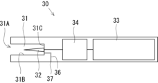
- FIG. 10 is a diagram illustrating the first half of the long flavor rod forming process according to the second manufacturing method. Reference numeral 110 shown in FIG.
- FIG. 10 denotes a conveyor that conveys various materials for manufacturing the flavor stick 1 along the direction of the white arrow (conveying direction) in the figure.
- the conveyor 110 conveys the long outer roll paper 22P.
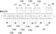
- FIG. 11 is a diagram illustrating the shape of the conveyor 110 in a cross-sectional direction orthogonal to the conveying direction.
- the conveyor 110 has a concave groove portion 110A along the conveying direction, and conveys the long outer roll paper 22P and other various materials while receiving them in the groove portion 110A.
- the groove bottom of the groove portion 110A of the conveyor 110 is formed with a suction hole that applies a suction pressure to the long outer roll paper 22P.
- the outer roll paper 22P is conveyed.
- the double-length leak suppressing member 4W is cut into two leak suppressing portions 4 by being bisected by a cutting knife at the central position in the longitudinal direction.
- the double-length leak suppressing member 4W is a member in which the leak suppressing portion 4 is double the length of the normal leak suppressing portion 4 (the length of the leak suppressing portion 4 as the final form incorporated in the flavor stick 1).
- the leak suppressing portion 4 corresponds to a “first component” that constitutes a part of the mouthpiece portion 3 .
- the first part may be a component arranged at the front end of the mouthpiece part 3 .
- a double-length leak suppressing member 4W having a double length of the leak suppressing portion 4 (first component) corresponds to a "double-length first component".
- Numerals 112 to 114 are first to third thin rod supply drums that supply double length thin rods 21W1 to 21W3 onto the long outer web 22P conveyed by the conveyor 110.
- the double-length thinly wound rods 21W1 to 21W3 are separated into two thinly wound rods 21 by being bisected at the center position in the longitudinal direction by a cutting knife. That is, the double-length thinly wound rods 21W1 to 21W3 are obtained by making the thinly wound rod 21 double the length of the normal thinly wound rod 21 (the length of the thinly wound rod 21 as the final form incorporated in the flavor stick 1).
- the double length thin wound rods 21W1-21W3 are substantially equivalent to thin wound rods in which the flavor source 24 is wound with the inner paper web 23 having twice the normal length.
- the leak suppression component supply drum 111 and the first to third thin winding rod supply drums 112 to 114 are arranged in this order from the upstream side of the conveying path by the conveyor 110 (first position P1 to fourth position P4).
- the leak suppression component supply drum 111 and the first to third thin rod supply drums 112 to 114 are positioned, for example, above the conveyor 110, and the rotation axis of each drum is perpendicular to the conveying direction of the conveyor 110.
- the leak suppression part supply drum 111 and the first to third thin rod supply drums 112 to 114 each sucked the parts to be supplied onto the long outer roll paper 22P conveyed by the conveyor 110 to the drum.
- the parts to be supplied are sequentially supplied onto the long outer roll paper 22P at a predetermined timing.
- Various materials are sequentially supplied to the supply drums 111 to 114 via hoppers, intermediate drums and the like (not shown).
- the leak suppression component supply drum 111 positioned at the first position P1 supplies the double length leak suppression member 4W onto the long outer paper roll 22P at regular intervals.
- the distance between the double-length leakage suppressing members 4W supplied onto the long outer paper roll 22P is substantially equal to the length of the double-length thin winding rods 21W1 to 21W3, and the double-length thin winding rods 21W1 to 21W3 are placed thereon. is formed as a rod mounting space S1.
- the first to third thin rod supply drums 112 to 114 positioned at the second position P2 to the fourth position P4 are placed in the rod mounting space S1 formed between the double length leak suppression members 4W.
- the length thin winding rods 21W1 to 21W3 are sequentially supplied.
- 12A and 12B are diagrams for explaining the state in which the leak suppression component supply drum 111 and the thin winding rod supply drums 112 to 114 supply various components at the first position P1 to the fourth position P4.
- the double-length leakage suppressing member 4W and the double-length thin winding rods 21W1 to 21W3 are sequentially supplied onto the long outer roll paper 22P conveyed by the conveyor 110.
- the double thin-wound rod 21W3 is supplied to the rod mounting space S1, so that the three double thin-wound rods 21W1 to 21W3 are bundled together, and these bundles form the double-length leakage suppressing member.
- the term “bundled” here means that the plurality of double-length thin winding rods 21W1 to 21W3 are arranged in parallel and close to each other.
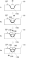
- FIG. 13 is a diagram explaining the second half of the long flavor rod forming process according to the second manufacturing method.
- the bundle of the double-length leak suppressing member 4W (double-length first part) and the double-length thin rods 21W1 to 21W3 (double-length thin rods) arranged in series therewith. (indicated by reference numeral 21W in the figure) is integrally wound up by the long outer winding paper 22P.
- a bundle of the double-length thin rods 21W1 to 21W3 and the double-length leakage suppressing member 4W are alternately arranged in the longitudinal direction, and these are integrally wound by the long outer winding paper 22P.
- a flavor rod 2P' is formed.
- a section of the long flavor rod 2P' where the bundle of the double-length thin rods 21W1 to 21W3 is arranged is called a "thin-wound rod section ST1", and a section where the double-length leak suppressing member 4W is arranged. This is called “leak component section ST2”.
- the winding of the bundle of the double-length thin rods 21W1 to 21W3 and the double-length leakage suppressing member 4W using the long outer winding paper 22P is the same as the long flavor rod forming process according to the first manufacturing method.
- a well-known tong (guide member) described in Japanese Patent No. 184625 may be used.
- the thin double-length rods 21W1 to 21W3 can be wound up by the long outer winding paper 22P while being compressed from the outside.
- the cross section of each of the double-length thin rods 21W1 to 21W3 in the thin rod section ST1 has an elliptical shape, and a hollow portion 25P extends in the longitudinal direction at the center of the cross section of the thin rod section ST1.
- a long flavor rod 2P' in which (heater insertion hole 25) is formed is obtained.
- FIG. 13 illustration of the conveyor 110 is omitted.
- Reference numeral 115 shown in FIG. 13 is the cutting knife of the hoist.
- the cutting knife 115 cuts the long flavor rod 2P' at the lengthwise center position of the double-length leakage suppressing member 4W and at the lengthwise center position of each of the double-length thin winding rods 21W1 to 21W3.
- the long flavor rod 2P' is cut at the central position of each of the thin winding rod section ST1 and the leak component section ST2.
- each of the double-length thinly wound rods 21W1 to 21W3 is separated into two thinly wound rods 21 by being cut at the central position in the longitudinal direction.
- the double-length leak suppressing member 4W is cut at the central position in the longitudinal direction, thereby separating the two leak suppressing portions 4.
- an intermediate assembly MA (see FIG. 14) can be formed in which the leak suppressing portion 4 is connected to the rear end of the flavor rod 2 that is a bundle of a plurality of thinly wound rods 21 .
- a single cutting knife 115 is used to cut the long flavor rod 2P' in the cutting step, but a plurality of cutting knives 115 are used to cut the long flavor rod 2P'.
- the first cutting knife and the second cutting knife are arranged at different positions along the conveying direction of the conveyor 110, the first cutting knife is used to cut the thin winding rod section ST1, and the second cutting is performed.
- a knife may be used to cut the leak component section ST2.
- Either the first cutting knife or the second cutting knife may be arranged upstream in the conveying direction of the conveyor 110 .
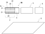
- FIG. 14 is a diagram showing the intermediate assembly MA formed in the process of forming the flavor rod, and separately prepared cooling section 5, filter section 6, and tipping paper 8.
- FIG. 14 the illustration of the leak suppression unit 4, the cooling unit 5, the filter unit 6, and the like is simplified.
- the cooling section 5 and the filter section 6 correspond to a “second component” that constitutes a part of the mouthpiece section 3 .
- the cooling part 5 and the filter part 6 corresponding to the second part can be said to be the rest of the parts constituting the mouthpiece part 3 excluding the leak suppressing part 4 corresponding to the first part.
- a second method of manufacturing the flavor stick 1 includes a connecting step.
- one or a plurality of second parts forming part of the mouthpiece part 3 are arranged in series with the leak suppressing part 4 corresponding to the first part in the intermediate assembly MA.
- intermediate assembly MA and one or more second parts are wound together by tipping paper 8 .
- the cooling section 5 and the filter section 6 each correspond to the second component. Therefore, as shown in FIG. 14, the cooling unit 5 and the filter unit 6 are arranged in series in this order at the rear end of the leak suppressing unit 4 in the intermediate assembly MA.
- the filter part 6 is wound up with the chip paper 8 and integrally connected.
- the flavor stick 1 is completed as shown in FIG. 15, illustration of the internal structures of the leak suppression unit 4, the cooling unit 5, and the filter unit 6 is omitted.
- the flavor inhaling device 30 includes a heating chamber 31, an internal heater 32, a power unit 33 that supplies operating power to the internal heater 32 to operate it, and a control unit 34 that controls the power supplied to the internal heater 32. etc.
- the heating chamber 31 is a substantially cylindrical hollow portion defined by a chamber-side peripheral wall 31B and a chamber bottom wall 31C that form part of the housing of the flavor inhaling device 30 .
- the internal heater 32 extends, for example, from the center of the chamber bottom wall 31C toward the insertion port 31A in parallel with the axial direction of the heating chamber 31 (insertion direction of the flavor stick 1). That is, the central axis of the internal heater 32 is coaxial with the central axis of the heating chamber 31 .
- it has a tapered conical shape whose diameter gradually decreases from the base end located on the side of the chamber bottom wall 31C toward the tip side located on the side of the insertion port 31A.
- the shape of the internal heater 32 is not particularly limited.
- the internal heater 32 may have a tapered truncated cone shape that gradually decreases in diameter from the proximal end located on the chamber bottom wall 31C side toward the distal end located on the insertion port 31A side. Further, the internal heater 32 may have a shape other than a conical shape or a truncated cone shape, for example, a columnar shape, or may have a blade shape or other shapes. Also, the type of the internal heater 32 is not particularly limited.
- the internal heater 32 may be, for example, a steel material with a heating wire (for example, nichrome, iron-chromium, iron-nickel, etc.) stretched therearound, or may be a ceramic heater or other heaters.
- the internal heater 32 is not limited to the resistance heating type heater as described above.
- the internal heater 32 is a heating element called a susceptor that generates heat by induction heating (IH).
- IH induction heating
- a susceptor that can be inserted into the heater insertion hole 25 of the flavor rod 2 is installed in the heating chamber 31, and an induction heating is provided in the heating chamber 31 for generating a high-frequency alternating magnetic field.
- Coils may be arranged around the heating chamber 31 . In this case, a high-frequency alternating magnetic field is generated in the heating chamber 31 by operating the induction coil, and the susceptor in the heating chamber 31 generates heat, thereby heating the flavor source 24 of each thin rod 21 .
- one end of the air flow path 36 communicates with the chamber bottom wall 31C.
- the other end of the air channel 35 communicates with an air intake 37 formed in the housing of the flavor inhaling device 30 .
- the flavor inhaling device 30 may start the heating operation triggered by a start-up operation of an operation switch or the like arranged on the housing. Further, the flavor suction device 30 may start the heating operation triggered by detecting that the flavor stick 1 (flavor rod 2) is inserted into the heating chamber 31 .
- the control unit 34 includes a sensor that detects insertion of the flavor stick 1 (flavor rod 2) into the heating chamber 31, and the detection of the insertion of the flavor stick 1 (flavor rod 2) by this sensor is triggered. You may start the operation of heating as .
- the power supply unit 33 is a power supply section that supplies electric power for heating to the internal heater 32 via the control section 34 .
- the control unit 34 accepts a request to start the heating operation triggered by, for example, the operation of the operation switch or the detection of the insertion of the flavor stick 1 into the heating chamber 31, and supplies the operating power to the internal heater 32. It is supplied to the power supply unit 33 .
- control unit 34 may include a temperature sensor that detects the temperature inside the heating chamber 31 or the temperature of the flavor rod unit 2. Based on the temperature detected by the temperature sensor, the temperature detected by the temperature sensor is transferred from the power supply unit 33 to the internal heater 32. The amount of current supplied may be adjusted.
- the heater insertion hole 25 is formed in the central portion of the cross section of the flavor rod 2, and the heater insertion hole 25 extends from the front end 1b along the central axis CL. are doing. Therefore, when inserting the flavor stick 1 (flavor rod 2 ) into the heating chamber 31 , the internal heater 32 can be smoothly inserted into the heater insertion hole 25 . In other words, mounting resistance when mounting the internal heater 32 on the flavor rod 2 can be reduced. This can improve the usability when attaching the flavor rod 2 to the heating chamber 31 . In addition, when the internal heater 32 is inserted into the flavor rod 2 , damage such as breakage or bending of the internal heater 32 and buckling deformation of the flavor rod 2 can be suppressed.
- a plurality of thinly wound rods 21 each having a flavor source 24 wound by an inner wound paper 23 are further bundled together by an outer wound paper 22, and the outer surface of the inner wound paper 23 in each thin rod 21 is A configuration is adopted in which the heater insertion hole 25 is defined (demarcated) by 23A.
- the heater can be inserted by defining the extension of the heater insertion hole 25 by the outer surface 23A of the inner web 23 of each thin roll 21 as described above.
- An inner web 23 can be interposed between the aperture 25 and the flavor source 24 .
- the internal heater 32 when inserting the internal heater 32 into the heater insertion hole 25 , the internal heater 32 directly contacts the outer surface 23 A of the inner paper roll 23 and does not directly contact the flavor source 24 . According to this, when attaching the internal heater 32 to the flavor rod 2, it is possible to prevent the internal heater 32 from being stained with the flavor source 24 attached thereto. That is, according to the flavor stick 1 of the present embodiment, it is possible to achieve both a reduction in mounting resistance when mounting the internal heater 32 on the flavor rod 2 and a suppression of adhesion of the flavor source 24 to the internal heater 32. Very good usability.
- the heater insertion hole 25 in the flavor rod 2 may be expanded in the cross-sectional direction by the inserted internal heater 32 .
- the heater insertion hole 25 is expanded by the internal heater 32, so that the width of each thinly wound rod 21 in the minor axis direction is reduced.
- the cross-sectional area of the outer peripheral gap 26 can be reduced by increasing the width of each thin rod 21 in the longitudinal direction.
- the flavor source 24 of each thinly-rolled rod 21 arranged around the heater insertion hole 25 is individually wound by the inner winding paper 23, so that each thinly-rolled rod 21
- the flavor source 24 can be prevented from spilling from the front end 1b side.
- a flavor rod in which a hollow portion for inserting a heater is not formed in the flavor source referred to as Comparative Example 1
- Comparative Example 1 when the internal heater is inserted into the flavor source, the flavor source is compressed by the volume of the internal heater.
- the ventilation resistance increases greatly.
- the filling amount of the flavor source with which the flavor rod is filled is adjusted so that the ventilation resistance after inserting the internal heater into the flavor source (that is, the ventilation resistance during suction) falls within an appropriate range. Need to adjust (reduce).
- the filling amount of the flavor source is adjusted as described above in Comparative Example 1, the flavor rod becomes too soft as a trade-off, and as a result, there is a risk that an appropriate hardness cannot be ensured for winding up the flavor rod using a winder.
- the flavor source 24 of each thinly wound rod 21 is individually wound by the inner winding paper 23 . Therefore, even if the filling amount of the flavor source 24 in each thinly wound rod 21 is small, the hardness of the flavor rod 2 as a whole can be properly ensured, and excellent suitability for manufacturing using a winding machine is provided.
- the flavor stick 1 configured as described above is made by inserting the flavor rod 2 into the heating chamber 31 of the flavor sucking device 30 and operating the internal heater 32 to generate the flavor source of each finely wound rod 21 . 24 are heated. As a result, the aerosol-generating base contained in the flavor source 24 is volatilized and the flavor component is released from the flavor source 24, resulting in the generation of an aerosol containing the flavor component.
- the aerosol containing the flavor component flows toward the mouthpiece portion 3 side (downstream side) in each finely wound rod 21 and flows into the mouthpiece portion 3 from the rear end of each finely wound rod 21 .
- the aerosol containing the flavor component sequentially passes through the aerosol flow path 41 of the leak suppressing section 4 located at the front end of the mouthpiece section 3, the cooling section 5, and the filter section 6, and finally flows from the mouthpiece end 1a to the user. is sucked into the mouth of the
- the flavor stick 1 has a leak suppressing portion 4 arranged at the front end portion of the mouthpiece portion 3 .
- the leak suppressing portion 4 has an aerosol flow path 41 extending in the axial direction, through which the aerosol generated in the plurality of thinly wound rods 21 flows, and is arranged to face the outer peripheral side gap 26 of the flavor rod 2. It has a blocking surface 42 (blocking portion). According to this, when the flavor stick 1 is sucked, the air taken into the flavor rod 2 from the front end 1b side can be prevented from leaking downstream through the outer peripheral side gap 26 .
- the position, size, and number of the aerosol flow paths 41 of the leak suppression unit 4 are not particularly limited as long as the aerosol flowing from each thin rod 21 can be circulated downstream.
- the leak suppressor 4 may have aerosol flow paths 41A to 41C in the axial direction for individually circulating the aerosols flowing from the thinly wound rods 21.
- the aerosol flow paths 41A to 41C are arranged to face each of the three thinly wound rods 21 in the flavor rod 2, and the aerosol from each thinly wound rod 21 can flow individually.
- the leak suppressing portion 4 in the present embodiment supports each thin rod 21 from behind as described above, and prevents each thin rod 21 from being pushed into the rear side of the stick. It also has a function as Therefore, even if frictional resistance is generated between the inner roll paper 23 and the inner heater 32 when the inner heater 32 is inserted into the heater insertion hole 25 of the flavor rod 2, each thinly rolled rod 21 is pushed to the rear side of the stick. can be suppressed.
- each thin winding rod 21 As a method for suppressing the positional deviation of each thin winding rod 21 as described above, it is possible to employ a mode in which the outer surface 23A of the inner winding paper 23 of the plurality of thin winding rods 21 is adhered to the inner surface 22A of the outer winding paper 22. .
- a long inner roll paper 23P corresponding to each of the long thin roll rods 21P1 to 21P3 and a length Glue (called “rail glue” in the technical field) for adhering the length outer roll paper 22P is applied linearly along the long direction of the long outer roll paper 22P, and then each of the long outer roll papers 22P is applied.
- the long thin rods 21P1 to 21P3 may be wound.
- the plurality of thinly wound rods 21 included in the flavor rod 2 may have the same type of flavor source 24, or may be different from each other.
- the first thin rolled rod 21 included in the flavor rod 2 may be filled with a flavor source 24 in the form of a homogenized sheet folded in a gathered shape inside the inner web 23 .
- the second thin rod 21 may be filled with a flavor source 24 in the form of shredded tobacco inside the inner paper roll 23 .
- the third thin roll 21 may be filled with a plant material (for example, herbal material) that does not contain tobacco components inside the inner paper roll 23 as the flavor source 24 .
- the thinly wound rods 21 may have different cross-sectional areas. According to this, the compounding amount of the flavor source 24 can be easily controlled according to the type of the flavor source 24 .
- each thin rod 21 in the flavor rod 2 is covered with the inner roll paper 23 on the outer peripheral side of the flavor source 24 . Therefore, the aerosols containing the flavor components emitted from the flavor sources 24 of the thin winding rods 21 are basically introduced into the mouthpiece portion 3 without being mixed with each other. According to this, when different types of flavor sources 24 are included in the plurality of thinly wound rods 21, the flavor of the flavor components contained in the aerosols emitted from the different types of flavor sources 24 can be made even more prominent.
- the mouthpiece portion 3 may have a channel structure for individually guiding the aerosols flowing from each of the plurality of thin winding rods 21 to the mouthpiece end 1a.
- the leak suppression unit 4 may have a structure having aerosol flow paths 41A to 41C in the axial direction for individually circulating the aerosols flowing from the thin winding rods 21, as in the configuration example shown in FIG. .
- the cooling part 5 for example, a sheet folded in a gathered shape is arranged, and a flow path is formed along the axial direction of the mouthpiece part 3 so that the aerosol flowing from each thin rod 21 is difficult to mix. structure can be exemplified.
- a plurality of thinly wound rods 21 are arranged around the heater insertion hole 25 .
- the heater insertion hole 25 can be arranged in the central region of the cross section of the flavor rod 2 , and the peripheral region can be effectively used as the arrangement region of the thinly wound rod 21 .
- each thin rod 21 in the flavor rod 2 has an elliptical cross section, and the short axis direction is arranged along the radial direction of the flavor rod 2 .
- the short axis direction of each thin rolled rod 21 having an elliptical cross section along the radial direction of the flavor rod 2 a region for forming the heater insertion hole 25 in the cross section center region of the flavor rod 2 is secured. becomes easier.
- the long axis of each thinly wound rod 21 can be easily arranged along the circumferential direction of the flavor rod 2, and the area of the outer peripheral side gap 26 can be reduced.
- the ratio of the cross-sectional area of the heater insertion hole 25 to the cross-sectional area of the flavor rod 2 is not particularly limited. By doing so, when the internal heater 32 is inserted into the heater insertion hole 25, excessive increase in frictional resistance between the inner paper roll 23 and the heater insertion hole 25 can be suppressed more effectively. As a result, it is possible to suitably prevent the inner paper roll 23 arranged around the heater insertion hole 25 from being wrinkled or torn. It is possible to suitably suppress the thin winding rod 21 from being pushed into the rear side of the stick.
- the number of thinly wound rods 21 included in the flavor rod 2 is not particularly limited as long as it is two or more. From the viewpoint of reducing the area, it is preferable to set the number of thinly wound rods 21 to three. Note that the number of thinly wound rods 21 may be changed along the axial direction of the flavor rod 2 . For example, three thin rods 21 may be arranged on the front end side of the flavor rod 2 and two thin rods 21 may be arranged on the rear end side of the flavor rod 2 .
- the inner paper roll 23 used for the thinly wound rod 21 preferably uses a material with high heat transfer performance in order to efficiently transfer heat from the inner heater 32 to the inner flavor source 24 . Therefore, it is preferable to use a material having a low basis weight and a high density for the inner paper roll 23 .
- a material having a low basis weight and a high density for the inner paper roll 23 For example, it is preferable to set the basis weight of the inner paper roll 23 to 10 gsm or more and 40 gsm or less and the density of the inner paper roll 23 to 1 g/cm 3 or more and 1.5 g/cm 3 or less.
- the inner winding paper 23 may be coated with a coating agent such as pectin or sodium alginate in order to improve its heat transfer performance.
- a material having excellent heat transfer performance such as aluminum laminated paper may be used.
- the air permeability of the inner paper roll 23 is set to 0 Coresta unit (CU) or more and 200 Coresta unit (CU) or less.
- CU Coresta unit
- CU Coresta unit
- the static friction coefficient between the inner heater 32 and the inner paper paper 23 is 0.45 or more and 0.75 or less, and the dynamic friction coefficient is It is preferable to adjust to be 0.4 or more and 0.7 or less.
- the tensile strength of the inner paper paper 23 is set to 10 to 20 N/15 mm, and the wet tensile strength of the inner paper roll 23 is set to 5 to 20 N/15 mm. preferable.
- the method for measuring the tensile strength of the inner paper roll 23 conforms to JIS P 8113, for example.
- the method for measuring the wet tensile strength of the inner paper roll 23 is based on, for example, the wet tensile strength test described in JP-A-2019-187451.
- the outer wrapping paper 22 of the flavor rod 2 is preferably made of wrapping paper with low heat transfer performance from the viewpoint of suppressing the escape of heat from the heating chamber 31 to the outside. Therefore, the outer web 22 is preferably made of a low basis weight and low density material. For example, it is preferable to set the basis weight of the outer roll paper 22 to 10 gsm or more and 40 gsm or less, and the density of the outer roll paper 22 to be 0.5 g/cm 3 or more and 1 g/cm 3 or less. Also, the outer paper roll 22 may be coated with a coating agent such as calcium carbonate or silicon dioxide to reduce heat transfer.
- a coating agent such as calcium carbonate or silicon dioxide
- the hardness of the thinly wound rod 21 is 60% or more and 85% or less when the inside of the inner paper roll 23 is filled with the flavor source 24 .
- the term "hardness” refers to the resistance of the thin wound rod 21 to deformation in the cross-sectional direction.
- the hardness of the finely wound rod 21 can be measured, for example, based on the test method described in Japanese Patent Publication No. 2019-506868 (paragraph 0029-0031, FIG. 1).
- a test for measuring the hardness of the thin wound rod 21 can also be performed using the standard operating procedure of a Borgwaldt Hardness Tester H10 (manufactured by Heinr Borgwaldt GmbH).
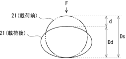
- the hardness of the finely wound rod 21 is obtained by the following formula.
- Hardness (%) (Dd/Ds) x 100
- Ds is the diametrical height of the finely wound rod 21 before being loaded by the Borgwaldt Hardness Tester H10
- Dd is the diametrical height of the finely wound rod 21 before being loaded by the Borgwaldt Hardness Tester H10 over a predetermined loading time (5 seconds). It is the height in the radial direction after a constant load (88 g) is applied to the thin winding rod 21 from the radial direction.
- 17A and 17B are diagrams for explaining an overview of hardness measurement of the finely wound rod 21.
- FIG. 18 is a cross-sectional view of a flavor rod 2A according to a modification of Embodiment 1.
- the flavor rod 2A according to Modification 1 has two thin rods 21 .
- the above-mentioned flavor rods with three thinly wound rods 21 are used.
- the basic structure are the same. That is, the flavor rod 2 has a heater insertion hole 25 formed in the central portion of its cross section, and two thinly wound rods 21 are arranged so as to surround the heater insertion hole 25 .
- the heater insertion hole 25 is different from the embodiment shown in FIG. 3 in that its cross-sectional shape is circular, but the shape of the heater insertion hole 25 is not particularly limited.
- the pair of thinly wound rods 21 has a cross section in which a substantially semicircular notch is provided in a part of an elliptical shape. As shown in FIG. 18, the pair of thinly wound rods 21 are arranged such that the semicircular notches are opposed to each other on the central axis CL side of the flavor rod 2A, and the longitudinal directions thereof are parallel.
- a circular heater insertion hole 25 is formed by combining the semicircular notches of the pair of thinly wound rods 21 .
- the short axis directions of the pair of thin rolled rods 21 are both arranged along the radial direction of the flavor rod 2A. ing.
- the flavor rod 2A shown in FIG. 18 is also integrally connected to the mouthpiece portion 3 via the tip paper 8 described above to form the flavor stick 1 (see FIG. 2).
- the flavor rod 2A according to this modified example can be basically manufactured by the same process as the flavor rod 2 of the 3 thin winding type.
- the thin two-roll type differs from the three thin-rolled rod type in that the number of thin-wound rods 21 is two.
- the long thin winding rods 21P1 and 21P2 are provided.
- the diameters (before compression) of the two long thin rods 21P1 and 21P2 may be set to about 4 mm to 4.5 mm.
- a mandrel is called between the two long thin winding rods 21P1 and 21P2.
- a core rod member is interposed.
- the mandrel has a cross section corresponding to the heater insertion hole 25, and is formed as a cylindrical rod body in this modification.
- the mandrel is sandwiched between the two long thin winding rods 21P1 and 21P2 and passed through the inside of the guide member.
- the two long thin roll rods 21P1 and 21P2 are compressed from the inside and outside by the inner wall surface of the cylindrical guide of the guide member and the mandrel, and the long outer roll paper 22P is formed into a cylindrical shape, which can be rolled up integrally.
- the cross section of the two long thin rods 21P1 and 21P2 becomes an elliptical shape partially having approximately semicircular concave portions 25P1 and 25P2 as shown in FIG. 19 due to the compression at the time of molding.
- the pair of recesses 25P1 and 25P2 form the heater insertion hole 25 of the flavor rod 2A by being combined.
- 19 indicates a cross section of the mandrel (core rod member).
- the area of the outer peripheral side gap 26 can be reduced.
- recesses 25P1 and 25P2 are formed in advance in the long thin winding rods 21P1 and 21P2 using the mandrel (core rod member), so that the central portion of the cross section of the flavor rod 2A
- the heater insertion hole 25 can be easily formed.
- the mandrel (core rod member) may be used when manufacturing the flavor rod 2 of the three thin winding type described above.
- the flavor source 24 is filled inside the inner side of the inner roll 23 of the thin rod 21.
- Various forms can be employed as long as they contain the flavor source and the aerosol-generating substrate.
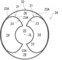
- FIG. 20 is a cross-sectional view of a flavor rod 2B according to Modification 2 of Embodiment 1.
- FIG. The flavor rod 2B according to Modification Example 2 differs from the above-described embodiments only in the form of the flavor source containing the aerosol disposed inside the inner paper roll 23 of the thinly wound rod 21, and the other configurations are the same. .
- a reference numeral 24A shown in FIG. 20 is a flavor source arranged inside the inner paper roll 23 .
- Flavor source 24A has a flavor source and an aerosol-generating substrate and a holding substrate 240 that holds them.
- the flavor source for example, any of the appropriate flavors listed above can be used.
- the holding substrate 240 of the flavor source 24A is a substrate sheet impregnated with and holding the liquid perfume and the liquid aerosol-generating substrate, and the material of the holding substrate includes non-woven fabric.
- the flavor with which the holding base material 240 (base material sheet) of the flavor source 24A is impregnated may not contain tobacco components.
- the holding base material 240 (base material sheet) of the flavor source 24A may be adhered along the inner surface of the inner roll paper 23 of the thin roll rod 21, for example.
- the thickness of the holding base material 240 (base material sheet) is not particularly limited.
- the flavor rod 2A according to the present modified example is produced by turning a long sheet-like base material sheet impregnated with a flavor source and an aerosol-generating base material into a long sheet-like thin roll rod in the above-described long thin roll rod forming step.
- a plurality of long thin rolled rods may be formed in parallel in the conveying direction of the winding machine by rolling up the roll paper continuously in the long direction into a circular cylinder shape. The cutting process is the same as in the embodiment described above.
- the type of flavor source (perfume) contained in the flavor source 24A of each thin rolled rod 21 may be the same or different.
- the holding base material 240 (base material sheet) of the flavor source 24A of each thin rod 21 has a cylindrical shape in cross section, but it is not limited to this.
- the cross section of the holding base material 240 (base material sheet) can adopt any shape, and may be, for example, a C-shape, an S-shape, a spiral shape, or the like.
- the inside of the inner web 23 may be filled with a base sheet impregnated with a liquid perfume and an aerosol-generating base material which is chopped into small pieces.
- some of the plurality of finely wound rods 21 included in the flavor rod 2A may be replaced with the finely wound rods 21 having the tobacco filling as the flavor source 24 as described in FIG.
- FIG. 21 is a diagram showing variations of the flavor source 24A in the thinly wound rod 21.
- the flavor source 24A (holding base material 240) has a C shape.
- the flavor source 24A (holding base material 240) has an S shape.
- the flavor source 24A (holding base material 240) has a meandering shape.
- the flavor source 24A (holding base material 240) has a spiral shape.
- the variation shown in FIG. 21 is also an example of the form of the flavor source 24A (holding base material 240).
- the flavor stick the non-combustion heating type flavor inhalation product, and the method for manufacturing the flavor stick according to the present invention are not limited to these. Also, each aspect disclosed in the embodiments and modifications described above can be combined with any other aspect disclosed in this specification.
- Flavor stick Flavor rod 3 Mouthpiece 21 Thin rod 22 Outer roll 23 Inner roll 24 Flavor source 25 Heater insertion hole
Landscapes
- Manufacture Of Tobacco Products (AREA)
- Cigarettes, Filters, And Manufacturing Of Filters (AREA)
Priority Applications (6)
| Application Number | Priority Date | Filing Date | Title |
|---|---|---|---|
| EP21961383.3A EP4420536A4 (en) | 2021-10-20 | 2021-10-20 | FLAVOR STICK, HEATING-NOT-COMBUSTION TYPE FLAVOR INHALATION PRODUCT, AND PROCESS FOR PRODUCING FLAVOR STICK |
| CN202180103453.5A CN118201506A (zh) | 2021-10-20 | 2021-10-20 | 香味棒、非燃烧加热式香味抽吸产品、以及香味棒的制造方法 |
| JP2023554155A JP7641401B2 (ja) | 2021-10-20 | 2021-10-20 | 香味スティック、非燃焼加熱式香味吸引製品、及び香味スティックの製造方法 |
| PCT/JP2021/038784 WO2023067730A1 (ja) | 2021-10-20 | 2021-10-20 | 香味スティック、非燃焼加熱式香味吸引製品、及び香味スティックの製造方法 |
| KR1020247013113A KR20240073068A (ko) | 2021-10-20 | 2021-10-20 | 향미 스틱, 비연소 가열식 향미 흡인 제품, 및 향미 스틱의 제조 방법 |
| US18/640,797 US20240260646A1 (en) | 2021-10-20 | 2024-04-19 | Flavor stick, heat-not-burn-type flavor inhalation product, and method for producing flavor stick |
Applications Claiming Priority (1)
| Application Number | Priority Date | Filing Date | Title |
|---|---|---|---|
| PCT/JP2021/038784 WO2023067730A1 (ja) | 2021-10-20 | 2021-10-20 | 香味スティック、非燃焼加熱式香味吸引製品、及び香味スティックの製造方法 |
Related Child Applications (1)
| Application Number | Title | Priority Date | Filing Date |
|---|---|---|---|
| US18/640,797 Continuation US20240260646A1 (en) | 2021-10-20 | 2024-04-19 | Flavor stick, heat-not-burn-type flavor inhalation product, and method for producing flavor stick |
Publications (1)
| Publication Number | Publication Date |
|---|---|
| WO2023067730A1 true WO2023067730A1 (ja) | 2023-04-27 |
Family
ID=86058035
Family Applications (1)
| Application Number | Title | Priority Date | Filing Date |
|---|---|---|---|
| PCT/JP2021/038784 Ceased WO2023067730A1 (ja) | 2021-10-20 | 2021-10-20 | 香味スティック、非燃焼加熱式香味吸引製品、及び香味スティックの製造方法 |
Country Status (6)
| Country | Link |
|---|---|
| US (1) | US20240260646A1 (https=) |
| EP (1) | EP4420536A4 (https=) |
| JP (1) | JP7641401B2 (https=) |
| KR (1) | KR20240073068A (https=) |
| CN (1) | CN118201506A (https=) |
| WO (1) | WO2023067730A1 (https=) |
Citations (5)
| Publication number | Priority date | Publication date | Assignee | Title |
|---|---|---|---|---|
| JPH07184625A (ja) | 1993-12-27 | 1995-07-25 | Japan Tobacco Inc | 紙巻たばこ製造機の刻たばこ給送装置 |
| JP5220762B2 (ja) | 2006-12-28 | 2013-06-26 | フィリップ・モーリス・プロダクツ・ソシエテ・アノニム | ロッドを通って延びる中空通路を有するタバコロッドを生産するための様々な実施形態 |
| JP2019187451A (ja) | 2015-03-27 | 2019-10-31 | フィリップ・モーリス・プロダクツ・ソシエテ・アノニム | 電気加熱式エアロゾル発生物品用の紙ラッパー |
| WO2020127107A1 (en) * | 2018-12-17 | 2020-06-25 | Philip Morris Products S.A. | Tubular element, comprising porous medium, for use with an aerosol generating article |
| WO2020194398A1 (ja) * | 2019-03-22 | 2020-10-01 | 日本たばこ産業株式会社 | 喫煙物品の製造方法 |
Family Cites Families (4)
| Publication number | Priority date | Publication date | Assignee | Title |
|---|---|---|---|---|
| JPS5220762B1 (https=) | 1970-12-28 | 1977-06-06 | ||
| MY170381A (en) * | 2011-12-30 | 2019-07-27 | Philip Morris Products Sa | Smoking article with front-plug and aerosol-forming substrate and method |
| WO2020213143A1 (ja) * | 2019-04-18 | 2020-10-22 | 日本たばこ産業株式会社 | 加熱式たばこ |
| CN112369667B (zh) * | 2020-08-19 | 2024-05-31 | 湖北中烟工业有限责任公司 | 一种加热不燃烧卷烟 |
-
2021
- 2021-10-20 JP JP2023554155A patent/JP7641401B2/ja active Active
- 2021-10-20 CN CN202180103453.5A patent/CN118201506A/zh active Pending
- 2021-10-20 EP EP21961383.3A patent/EP4420536A4/en active Pending
- 2021-10-20 WO PCT/JP2021/038784 patent/WO2023067730A1/ja not_active Ceased
- 2021-10-20 KR KR1020247013113A patent/KR20240073068A/ko active Pending
-
2024
- 2024-04-19 US US18/640,797 patent/US20240260646A1/en active Pending
Patent Citations (5)
| Publication number | Priority date | Publication date | Assignee | Title |
|---|---|---|---|---|
| JPH07184625A (ja) | 1993-12-27 | 1995-07-25 | Japan Tobacco Inc | 紙巻たばこ製造機の刻たばこ給送装置 |
| JP5220762B2 (ja) | 2006-12-28 | 2013-06-26 | フィリップ・モーリス・プロダクツ・ソシエテ・アノニム | ロッドを通って延びる中空通路を有するタバコロッドを生産するための様々な実施形態 |
| JP2019187451A (ja) | 2015-03-27 | 2019-10-31 | フィリップ・モーリス・プロダクツ・ソシエテ・アノニム | 電気加熱式エアロゾル発生物品用の紙ラッパー |
| WO2020127107A1 (en) * | 2018-12-17 | 2020-06-25 | Philip Morris Products S.A. | Tubular element, comprising porous medium, for use with an aerosol generating article |
| WO2020194398A1 (ja) * | 2019-03-22 | 2020-10-01 | 日本たばこ産業株式会社 | 喫煙物品の製造方法 |
Non-Patent Citations (1)
| Title |
|---|
| See also references of EP4420536A4 |
Also Published As
| Publication number | Publication date |
|---|---|
| EP4420536A1 (en) | 2024-08-28 |
| EP4420536A4 (en) | 2025-09-03 |
| JP7641401B2 (ja) | 2025-03-06 |
| KR20240073068A (ko) | 2024-05-24 |
| CN118201506A (zh) | 2024-06-14 |
| JPWO2023067730A1 (https=) | 2023-04-27 |
| US20240260646A1 (en) | 2024-08-08 |
Similar Documents
| Publication | Publication Date | Title |
|---|---|---|
| KR102800202B1 (ko) | 비연소 가열형 흡연 물품, 전기 가열형 흡연 시스템 및 비연소 가열형 흡연 물품의 제조 방법 | |
| CN115551371A (zh) | 吸烟系统 | |
| US20240260643A1 (en) | Flavor stick, non-combustion heating type flavor inhaler product, and production method for flavor stick | |
| EP3881687A1 (en) | Filter segment, non-combustion heating type smoking article and non-combustion heating type smoking system | |
| WO2022259505A1 (ja) | 先端部にキャップ部材を備える香味源含有ロッド | |
| WO2020100876A1 (ja) | 非燃焼加熱喫煙物品及び非燃焼加熱喫煙システム | |
| WO2023089769A1 (ja) | たばこ製品用のフィルターセグメント、その製造方法、及びその製造装置、並びにたばこ製品 | |
| US20240260644A1 (en) | Flavor stick, heat-not-burn-type flavor inhalation product, and method for producing flavor stick | |
| JP7641401B2 (ja) | 香味スティック、非燃焼加熱式香味吸引製品、及び香味スティックの製造方法 | |
| WO2021070328A1 (ja) | 非燃焼加熱型香味吸引器具 | |
| WO2023067732A1 (ja) | シガレット、及びその製造方法 | |
| WO2024157477A1 (ja) | 香味スティック、非燃焼加熱式香味吸引製品、及び香味ロッドの製造方法 | |
| WO2023067728A1 (ja) | シガレット、及びその製造方法 | |
| WO2024157480A1 (ja) | 香味スティック、非燃焼加熱式香味吸引製品、及び香味ロッドの製造方法 | |
| WO2024157479A1 (ja) | 香味スティック、非燃焼加熱式香味吸引製品、及び香味ロッドの製造方法 | |
| KR20250115454A (ko) | 향미 스틱, 비연소 가열식 향미 흡인 제품, 및 향미 로드를 제조하는 방법 | |
| RU2772361C1 (ru) | Сегмент фильтра, курительное изделие с нагревом без горения и курительная система с нагревом без горения | |
| HK40055631A (en) | Filter segment, non-combustion heating type smoking article and non-combustion heating type smoking system |
Legal Events
| Date | Code | Title | Description |
|---|---|---|---|
| 121 | Ep: the epo has been informed by wipo that ep was designated in this application |
Ref document number: 21961383 Country of ref document: EP Kind code of ref document: A1 |
|
| WWE | Wipo information: entry into national phase |
Ref document number: 2023554155 Country of ref document: JP |
|
| WWE | Wipo information: entry into national phase |
Ref document number: 202180103453.5 Country of ref document: CN |
|
| ENP | Entry into the national phase |
Ref document number: 20247013113 Country of ref document: KR Kind code of ref document: A |
|
| WWE | Wipo information: entry into national phase |
Ref document number: 2021961383 Country of ref document: EP |
|
| NENP | Non-entry into the national phase |
Ref country code: DE |
|
| ENP | Entry into the national phase |
Ref document number: 2021961383 Country of ref document: EP Effective date: 20240521 |