WO2023067496A1 - Safe low-voltage conductive ground-installed connecting device for statically and dynamically charging electric vehicles - Google Patents
Safe low-voltage conductive ground-installed connecting device for statically and dynamically charging electric vehicles Download PDFInfo
- Publication number
- WO2023067496A1 WO2023067496A1 PCT/IB2022/059996 IB2022059996W WO2023067496A1 WO 2023067496 A1 WO2023067496 A1 WO 2023067496A1 IB 2022059996 W IB2022059996 W IB 2022059996W WO 2023067496 A1 WO2023067496 A1 WO 2023067496A1
- Authority
- WO
- WIPO (PCT)
- Prior art keywords
- conduit
- slot
- cavity
- contact surface
- roadway
- Prior art date
Links
Images


Classifications
-
- B—PERFORMING OPERATIONS; TRANSPORTING
- B60—VEHICLES IN GENERAL
- B60L—PROPULSION OF ELECTRICALLY-PROPELLED VEHICLES; SUPPLYING ELECTRIC POWER FOR AUXILIARY EQUIPMENT OF ELECTRICALLY-PROPELLED VEHICLES; ELECTRODYNAMIC BRAKE SYSTEMS FOR VEHICLES IN GENERAL; MAGNETIC SUSPENSION OR LEVITATION FOR VEHICLES; MONITORING OPERATING VARIABLES OF ELECTRICALLY-PROPELLED VEHICLES; ELECTRIC SAFETY DEVICES FOR ELECTRICALLY-PROPELLED VEHICLES
- B60L5/00—Current collectors for power supply lines of electrically-propelled vehicles
- B60L5/40—Current collectors for power supply lines of electrically-propelled vehicles for collecting current from lines in slotted conduits
-
- B—PERFORMING OPERATIONS; TRANSPORTING
- B60—VEHICLES IN GENERAL
- B60L—PROPULSION OF ELECTRICALLY-PROPELLED VEHICLES; SUPPLYING ELECTRIC POWER FOR AUXILIARY EQUIPMENT OF ELECTRICALLY-PROPELLED VEHICLES; ELECTRODYNAMIC BRAKE SYSTEMS FOR VEHICLES IN GENERAL; MAGNETIC SUSPENSION OR LEVITATION FOR VEHICLES; MONITORING OPERATING VARIABLES OF ELECTRICALLY-PROPELLED VEHICLES; ELECTRIC SAFETY DEVICES FOR ELECTRICALLY-PROPELLED VEHICLES
- B60L53/00—Methods of charging batteries, specially adapted for electric vehicles; Charging stations or on-board charging equipment therefor; Exchange of energy storage elements in electric vehicles
- B60L53/10—Methods of charging batteries, specially adapted for electric vehicles; Charging stations or on-board charging equipment therefor; Exchange of energy storage elements in electric vehicles characterised by the energy transfer between the charging station and the vehicle
- B60L53/14—Conductive energy transfer
-
- B—PERFORMING OPERATIONS; TRANSPORTING
- B60—VEHICLES IN GENERAL
- B60M—POWER SUPPLY LINES, AND DEVICES ALONG RAILS, FOR ELECTRICALLY- PROPELLED VEHICLES
- B60M1/00—Power supply lines for contact with collector on vehicle
- B60M1/30—Power rails
- B60M1/34—Power rails in slotted conduits
-
- B—PERFORMING OPERATIONS; TRANSPORTING
- B60—VEHICLES IN GENERAL
- B60M—POWER SUPPLY LINES, AND DEVICES ALONG RAILS, FOR ELECTRICALLY- PROPELLED VEHICLES
- B60M7/00—Power lines or rails specially adapted for electrically-propelled vehicles of special types, e.g. suspension tramway, ropeway, underground railway
-
- B—PERFORMING OPERATIONS; TRANSPORTING
- B66—HOISTING; LIFTING; HAULING
- B66F—HOISTING, LIFTING, HAULING OR PUSHING, NOT OTHERWISE PROVIDED FOR, e.g. DEVICES WHICH APPLY A LIFTING OR PUSHING FORCE DIRECTLY TO THE SURFACE OF A LOAD
- B66F9/00—Devices for lifting or lowering bulky or heavy goods for loading or unloading purposes
- B66F9/06—Devices for lifting or lowering bulky or heavy goods for loading or unloading purposes movable, with their loads, on wheels or the like, e.g. fork-lift trucks
- B66F9/063—Automatically guided
-
- B—PERFORMING OPERATIONS; TRANSPORTING
- B66—HOISTING; LIFTING; HAULING
- B66F—HOISTING, LIFTING, HAULING OR PUSHING, NOT OTHERWISE PROVIDED FOR, e.g. DEVICES WHICH APPLY A LIFTING OR PUSHING FORCE DIRECTLY TO THE SURFACE OF A LOAD
- B66F9/00—Devices for lifting or lowering bulky or heavy goods for loading or unloading purposes
- B66F9/06—Devices for lifting or lowering bulky or heavy goods for loading or unloading purposes movable, with their loads, on wheels or the like, e.g. fork-lift trucks
- B66F9/075—Constructional features or details
- B66F9/07504—Accessories, e.g. for towing, charging, locking
-
- B—PERFORMING OPERATIONS; TRANSPORTING
- B66—HOISTING; LIFTING; HAULING
- B66F—HOISTING, LIFTING, HAULING OR PUSHING, NOT OTHERWISE PROVIDED FOR, e.g. DEVICES WHICH APPLY A LIFTING OR PUSHING FORCE DIRECTLY TO THE SURFACE OF A LOAD
- B66F9/00—Devices for lifting or lowering bulky or heavy goods for loading or unloading purposes
- B66F9/06—Devices for lifting or lowering bulky or heavy goods for loading or unloading purposes movable, with their loads, on wheels or the like, e.g. fork-lift trucks
- B66F9/075—Constructional features or details
- B66F9/20—Means for actuating or controlling masts, platforms, or forks
- B66F9/205—Arrangements for transmitting pneumatic, hydraulic or electric power to movable parts or devices
-
- E—FIXED CONSTRUCTIONS
- E01—CONSTRUCTION OF ROADS, RAILWAYS, OR BRIDGES
- E01B—PERMANENT WAY; PERMANENT-WAY TOOLS; MACHINES FOR MAKING RAILWAYS OF ALL KINDS
- E01B25/00—Tracks for special kinds of railways
- E01B25/28—Rail tracks for guiding vehicles when running on road or similar surface
-
- E—FIXED CONSTRUCTIONS
- E01—CONSTRUCTION OF ROADS, RAILWAYS, OR BRIDGES
- E01C—CONSTRUCTION OF, OR SURFACES FOR, ROADS, SPORTS GROUNDS, OR THE LIKE; MACHINES OR AUXILIARY TOOLS FOR CONSTRUCTION OR REPAIR
- E01C9/00—Special pavings; Pavings for special parts of roads or airfields
- E01C9/02—Wheel tracks
-
- B—PERFORMING OPERATIONS; TRANSPORTING
- B60—VEHICLES IN GENERAL
- B60L—PROPULSION OF ELECTRICALLY-PROPELLED VEHICLES; SUPPLYING ELECTRIC POWER FOR AUXILIARY EQUIPMENT OF ELECTRICALLY-PROPELLED VEHICLES; ELECTRODYNAMIC BRAKE SYSTEMS FOR VEHICLES IN GENERAL; MAGNETIC SUSPENSION OR LEVITATION FOR VEHICLES; MONITORING OPERATING VARIABLES OF ELECTRICALLY-PROPELLED VEHICLES; ELECTRIC SAFETY DEVICES FOR ELECTRICALLY-PROPELLED VEHICLES
- B60L2200/00—Type of vehicles
- B60L2200/36—Vehicles designed to transport cargo, e.g. trucks
-
- B—PERFORMING OPERATIONS; TRANSPORTING
- B62—LAND VEHICLES FOR TRAVELLING OTHERWISE THAN ON RAILS
- B62D—MOTOR VEHICLES; TRAILERS
- B62D1/00—Steering controls, i.e. means for initiating a change of direction of the vehicle
- B62D1/24—Steering controls, i.e. means for initiating a change of direction of the vehicle not vehicle-mounted
- B62D1/26—Steering controls, i.e. means for initiating a change of direction of the vehicle not vehicle-mounted mechanical, e.g. by a non-load-bearing guide
- B62D1/265—Steering controls, i.e. means for initiating a change of direction of the vehicle not vehicle-mounted mechanical, e.g. by a non-load-bearing guide especially adapted for guiding road vehicles carrying loads or passengers, e.g. in urban networks for public transportation
Definitions
- a small groove 15 is planed in the floor 16 by a rotary cutter 22 with a horizontal axis.
- the conduit 1 is unwound from the reel 21 and straightened by the bender 23 then by a roller guide assembly 24 realigned with the groove 15 in which the conduit 1 is deposited and possibly fixed by gluing.
- a shearing device (not shown) will be used to cover the width of the coil and an alternative solution by lateral displacement of the coil can be considered if the cutter 22 and the coil 21 are on the same construction vehicle (not shown) .
Abstract
The invention relates to a device for supplying electric power to electric vehicles (139) comprising: one or more traction batteries; at least one current collector (140) integrated into the vehicles (139); and, in the ground, at least one fixed power duct substantially parallel to the direction of movement of the vehicles (139), comprising a vertical slit, which opens into a cavity of the duct for receiving the current collector (140), the cavity containing at least one electrical contact surface connected to a fixed current source by a power cable, the contact surface being located set back from a route of direct access through said slit, characterized in that the electrical contact surface is positioned in the cavity of the duct as an inclined cornice. This device is further characterized in that the slit has a width smaller than the safety standard according to which it must be impossible for a finger to be able to penetrate into the slit, which width is currently set to 12 mm in Europe (IEC 60529).
Description
La présente invention concerne un dispositif de connexion électrique pour la charge statique et dynamique des véhicules électriques.The present invention relates to an electrical connection device for the static and dynamic charging of electric vehicles.
L’électrification du parc automobile, véhicules légers, véhicules utilitaires, autocars, poids lourds se heurte au problème de la charge des batteries de ces véhicules qui d’une part requiert : a) l’immobilisation du véhicule et b) la mise en place d’un câble manuellement reliant la source électrique au chargeur embarqué. The electrification of the car fleet, light vehicles, utility vehicles, coaches, heavy goods vehicles comes up against the problem of charging the batteries of these vehicles which on the one hand requires: a) the immobilization of the vehicle and b) the installation a cable manually connecting the electrical source to the on-board charger.
Dans la demande PCT/IB2021/051187, qui a fait l'objet d'une publication WO 2021/161247, le déposant proposait un mode de circulation hautement automatisé pour les véhicules électriques avec une alimentation en TBTS (Très Basse Tension de Sécurité) limitée à 120 volts en courant continu mais cette configuration engendre des intensités trop importantes pour alimenter des poids lourds en charge rapide notamment pour les autobus urbain aux arrêts.In application PCT/IB2021/051187, which was the subject of publication WO 2021/161247, the applicant proposed a highly automated mode of circulation for electric vehicles with a limited SELV (Very Low Safety Voltage) supply. at 120 volts direct current, but this configuration generates intensities that are too high to supply fast charging heavy goods vehicles, in particular for urban buses at stops.
La présente invention apporte une solution nouvelle pour connecter en BT (Basse Tension < 1 000 volts AC et 1 500 volts DC) les véhicules électriques à une source électrique fixe, par l’intermédiaire d’un conduit de chaussée, permettant une charge dynamique, possédant d’une part sur sa face supérieure une fente de largeur inférieure à la norme de sécurité prévenant la pénétration d’un doigt dans la fente, largeur fixée actuellement à 12 mm en Europe (IEC 60529) et d’autre part une géométrie particulière qui permet de placer les surfaces de contact sous tension en corniche inclinée dans une cavité rendant impossible l’accès accidentel des doigts aux surfaces sous tension. Ce conduit est destiné à être installé sur les voies de circulation des autoroutes et voies rapides ou la présence de personne est restreinte. The present invention provides a new solution for connecting LV (Low Voltage < 1,000 volts AC and 1,500 volts DC) electric vehicles to a fixed electrical source, via a roadway conduit, allowing dynamic charging, having on the one hand on its upper face a slot of width less than the safety standard preventing the penetration of a finger into the slot, width currently fixed at 12 mm in Europe (IEC 60529) and on the other hand a particular geometry which makes it possible to place the live contact surfaces in an inclined ledge in a cavity making it impossible for the fingers to accidentally access the live surfaces. This conduit is intended to be installed on the traffic lanes of motorways and expressways where the presence of people is restricted.
De ce fait, la présente invention décrit un dispositif d’alimentation électrique de véhicules automobiles comportant une batterie de traction, un collecteur de courant par un conduit d’alimentation fixé au sol sensiblement parallèle à la direction du déplacement du véhicule, comportant une fente pour le passage du collecteur de courant, contenant des surfaces de contact électrique reliées à une source fixe de courant par des câbles d’alimentation, les surfaces de contact se trouvant en retrait d’un accès direct par la fente, caractérisées en ce qu’elles sont positionnées dans le conduit en corniche inclinée pour une sécurité respectant la norme.Therefore, the present invention describes a power supply device for motor vehicles comprising a traction battery, a current collector via a supply conduit fixed to the ground substantially parallel to the direction of movement of the vehicle, comprising a slot for the passage of the current collector, containing electrical contact surfaces connected to a fixed current source by supply cables, the contact surfaces being set back from direct access by the slot, characterized in that they are positioned in the duct as an inclined cornice for standard-compliant safety.
Le conduit, de longueur excédant les limites du transport routier, comporte un corps en polymère permettant l’enroulement dudit conduit sur bobine de dimensions inférieures au gabarit routier ce qui lui confère un comportement similaire à celui d’un câble. The conduit, of length exceeding the limits of road transport, comprises a polymer body allowing the winding of said conduit on a reel of dimensions less than the road gauge, which gives it a behavior similar to that of a cable.
Le conduit selon l’invention est préférablement installé dans une rainure rabotée dans la chaussée, la surface supérieure du conduit affleurant la chaussée.The conduit according to the invention is preferably installed in a planed groove in the roadway, the upper surface of the conduit being flush with the roadway.
Dans un autre mode de réalisation de l’invention, le conduit est fixé sur la chaussée et le corps élastomère de part et d’autre du conduit présente une surface transversale, rattrapant le niveau de la chaussée, en pente douce.In another embodiment of the invention, the conduit is fixed to the roadway and the elastomeric body on either side of the conduit has a transverse surface, catching up with the level of the roadway, on a gentle slope.
La surface de contact présente, sur la face débouchant dans la cavité, un faible coefficient de friction et une bonne résistante à l’abrasion par des moyens connus et la connexion électrique se fait sur l’autre face opposée par contact latéral direct avec le câble d’alimentation. The contact surface has, on the face opening into the cavity, a low coefficient of friction and good resistance to abrasion by known means and the electrical connection is made on the other opposite face by direct lateral contact with the cable. power supply.
Le forage de trous successifs d’évacuation d’eau à travers la dalle béton dans la rainure est réalisé en cas de chaussée revêtue d’un enrobé non drainant. The drilling of successive water evacuation holes through the concrete slab in the groove is carried out in the case of a road surfaced with a non-draining asphalt.
Le corps en élastomère du conduit est renforcé par au moins un profilé métallique continu ouvert, ce profilé comportant des découpes transversales partielles réduisant ainsi l’inertie en flexion dans le plan de la fenteThe elastomer body of the duct is reinforced by at least one continuous open metal profile, this profile comprising partial transverse cutouts thus reducing the inertia in bending in the plane of the slot
Les câbles d’alimentation sont monobrins et le profilé métallique est ouvert de façon à ce que le conduit puisse être :
- fléchi plastiquement en sortie de chaîne de fabrication pour s’enrouler sur la bobine de transport et
- redressé lors de l’installation dans la rainure par un ensemble de cintrage à galets.
- plastically bent at the end of the production line to roll up on the transport reel and
- straightened when installed in the groove by a roller bending assembly.
Du fait des sections substantielles des câbles d’alimentation, le pliage et dépliage longitudinal de la face inférieure découpée transversalement du profilé métallique autour d’un axe permet d’introduire les câbles d’alimentation.Due to the substantial sections of the power cables, the longitudinal folding and unfolding of the transversely cut underside of the metal profile around an axis allows the introduction of the power cables.
Les bordures de fente sont métalliques et reliées électriquement à la « terre » et ont une hauteur égale ou supérieure à la largeur de la fente, le collecteur porté par le véhicule étant en contact avec au moins une des bordures métalliques.The slot edges are metallic and electrically grounded and have a height equal to or greater than the width of the slot, with the collector carried by the vehicle in contact with at least one of the metallic edges.
De préférence les câbles d’alimentation sont en aluminium avec des surfaces de contact en cuivre ou en acier, éventuellement inoxydable, et les surfaces de contact présentent des découpes transversales partielles réduisant l’inertie en flexion dans le plan de ladite fente.Preferably, the power cables are made of aluminum with contact surfaces of copper or steel, possibly stainless steel, and the contact surfaces have partial transverse cutouts reducing the bending inertia in the plane of said slot.
Le conduit est alimenté en courant continu et comporte deux surfaces de contact électrique positionnées en corniche inclinée de part et d’autre de la fente dans une cavité, avantageusement l’une est alimentée en basse tension d’une différence de potentiel inférieur à la "terre" et l’autre en basse tension d’une différence de potentiel supérieur à la "terre". De préférence, les tensions en courant continu pourront être de + 400 volts et – 400 volts.The conduit is supplied with direct current and comprises two electrical contact surfaces positioned in an inclined ledge on either side of the slot in a cavity, advantageously one is supplied with low voltage with a potential difference lower than the " ground" and the other low voltage with a potential difference greater than "ground". Preferably, the direct current voltages may be +400 volts and -400 volts.
Les véhicules comportent sous leur structure un collecteur déplaçable latéralement, comportant un moyen de rétraction verticale permettant la connexion électrique avec les surfaces de contact en position basse et permettant en position haute de préserver la garde au sol de ces véhicules.The vehicles comprise under their structure a laterally movable manifold, comprising a vertical retraction means allowing electrical connection with the contact surfaces in the low position and allowing the high position to preserve the ground clearance of these vehicles.
Le déplacement latéral du collecteur consiste en un bras pantographe pivotant latéralement sur son attache ou alternativement coulissant sur un rail transversal solidaire de la structure du véhicule.The lateral displacement of the collector consists of a pantograph arm pivoting laterally on its attachment or alternatively sliding on a transverse rail integral with the structure of the vehicle.
Le collecteur de courant dynamique comporte au moins un frotteur conducteur pouvant basculer dans la cavité du conduit par rapport à un axe longitudinal situé en dessous de la face supérieure dudit conduit.The dynamic current collector comprises at least one conductive shoe that can tilt in the cavity of the duct with respect to a longitudinal axis located below the upper face of said duct.
Le conduit comporte à la base de la cavité des orifices d’évacuation d’eau pluviales et débris de dimensions supérieures à la largeur de ladite fente.The conduit comprises at the base of the cavity rainwater and debris evacuation orifices of dimensions greater than the width of said slot.
Pour la charge statique le conduit est de courte longueur fixé sur la chaussée et ne nécessite pas d’être fléchissable. Le corps en polymère de part et d’autre du conduit présente une forme de dos d’âne longitudinal pour rattraper latéralement en pente douce le niveau de la chaussée. L’emplacement des surfaces de contact pourra être avantageusement identique à celui pour une charge dynamique, le même collecteur pouvant alors réaliser les charges statiques et dynamiques. Dans le cas de charge en parking couvert, la charge étant limté a20 kW, communément en courant alternatif, un système de commutation connu permettra la recharge de la batterie de traction, bien que prenant plus de temps.For the static load, the duct is of short length fixed to the roadway and does not need to be bendable. The polymer body on either side of the duct has the shape of a longitudinal humpback to gently slope laterally to catch up with the level of the roadway. The location of the contact surfaces may advantageously be identical to that for a dynamic load, the same collector then being able to carry out the static and dynamic loads. In the case of charging in covered parking, the charge being limited to 20 kW, commonly in alternating current, a known switching system will allow the recharging of the traction battery, although taking more time.
Des moyens connus permettent de placer le collecteur à la verticale de la fente lors de son déploiement et de basculer les frotteurs latéralement pour entrer en contact avec les surfaces de contact en corniche inclinée après pénétration dans la cavité par la fente.Known means make it possible to place the collector vertically to the slot during its deployment and to tilt the shoes laterally to come into contact with the inclined cornice contact surfaces after penetration into the cavity through the slot.
D'autres caractéristiques et avantages de l'invention ressortiront de la description donnée ci-après d'un exemple de sa réalisation. Il sera fait référence aux dessins annexés parmi lesquels :
Other characteristics and advantages of the invention will emerge from the description given below of an example of its embodiment. Reference will be made to the appended drawings, including:
Other characteristics and advantages of the invention will emerge from the description given below of an example of its embodiment. Reference will be made to the appended drawings, including:
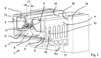
La illustre le conduit 1 comprenant une fente 12 de largeur « L » inférieure à la norme de sécurité prévenant la pénétration d’un doigt dans la fente fixée actuellement à 12 mm en Europe (IEC 60529). Le conduit 1 contient :
- les surfaces de
contact 2 et 3 en corniche inclinée qui comportent des découpes transversales inclinées 13, débouchant en partie basse pour réduire fortement leur résistance à la flexion dans le plan de symétrie du conduit, - les câbles d’alimentation 5 et 6, qui portent les surfaces de
contact 2 et 3 peuvent avantageusement dans le mode de réalisation pour charge dynamique, être reliés à des pôles de différences de potentiel supérieur et inférieur à la "terre", - les câbles d’alimentation 7a et 7b sont reliés au neutre, ils sont de sections substantielles car dans le cas d’une alimentation en bi-voltage 400volts/800volts le passage de l‘intensité se fera entre un pôle et le neutre en 400 volts et entre les deux pôles en 800 volts.
- le profilé métallique 4 qui avantageusement comporte des découpes transversales 10 pour réduire sa résistance à la flexion dans le plan de la
fente 12 et desdécoupes 14 dans les parties affleurant la surface de la chaussée pour laisser le corps enpolymère 9 traverser et augmenter le coefficient de non-glissance SRT. Cette obligation peut également être respectée par une peinture rugueuse. -
le corps 9 contient une cavité 8 à pente inclinée pour permettre à l’eau de pluie de s’écouler par les trous transversaux 11a débouchant dans les canaux latéraux 17 entre chaussée et conduit, délimités par la rainure 15 rabotée dans la chaussée 16.Le corps 9 pourra avantageusement comporter des trous 11 longitudinaux aux fins de transmission d’informations diverses (températures,…) ou de puissance en moyenne tension notamment.
- the contact surfaces 2 and 3 in inclined cornice which comprise inclined
transverse cutouts 13, emerging in the lower part to greatly reduce their resistance to bending in the plane of symmetry of the conduit, - the
supply cables - the
power cables - the
metal profile 4 which advantageously comprisestransverse cutouts 10 to reduce its resistance to bending in the plane of theslot 12 andcutouts 14 in the parts flush with the surface of the roadway to let thepolymer body 9 pass through and increase the coefficient of non-slip SRT. This obligation can also be fulfilled by a rough paint. - the
body 9 contains acavity 8 with an inclined slope to allow rainwater to flow through thetransverse holes 11a opening into theside channels 17 between roadway and duct, delimited by thegroove 15 planed in theroadway 16. Thebody 9 may advantageously includelongitudinal holes 11 for the purpose of transmitting various information (temperatures, etc.) or medium voltage power in particular.
La illustre le profilé métallique 4’ fléchi plastiquement pour permettre l’enroulement sur la bobine 21 de la .There illustrates the metal profile 4 'plastically bent to allow the winding on the coil 21 of the .
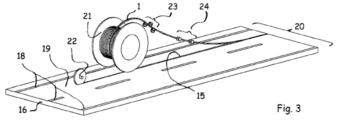
La illustre l’installation sur la voie de droite 19 d’une autoroute ou voie rapide 20 bordée par des lignes de rive ou bandes blanches 18. Une rainure de faible dimension 15 est rabotée dans la chaussée 16 par une fraise rotative 22 à axe horizontal. Le conduit 1 est déroulé de la bobine 21 et redressé par la cintreuse 23 puis par un ensemble de guidage à rouleaux 24 réaligné avec la rainure 15 dans laquelle le conduit 1 est déposé et fixé éventuellement par collage. Un dispositif de trancanage (non illustré) sera utilisé pour couvrir la largeur de la bobine et une solution alternative par déplacement latérale de la bobine pourra être considéré si la fraise 22 et la bobine 21 se trouvent sur le même véhicule de chantier (non illustré).There illustrates the installation on the right lane 19 of a highway or expressway 20 bordered by shore lines or white bands 18. A small groove 15 is planed in the floor 16 by a rotary cutter 22 with a horizontal axis. The conduit 1 is unwound from the reel 21 and straightened by the bender 23 then by a roller guide assembly 24 realigned with the groove 15 in which the conduit 1 is deposited and possibly fixed by gluing. A shearing device (not shown) will be used to cover the width of the coil and an alternative solution by lateral displacement of the coil can be considered if the cutter 22 and the coil 21 are on the same construction vehicle (not shown) .
Les figures 4 et 5 illustrent une méthode pour introduire, avant extrusion du corps élastomère 9 sur le profilé métallique 4, les câbles d’alimentation rigides 5, 6, 7 et 8 dans le profilé métallique 4a qui a été formé par profilage de tôle avec un pli 25. Dans la , on voit les câbles d’alimentation 5, 7a et 7b déjà à l’intérieur du profilé 4a et le câble d’alimentation 6 avec sa gaine d’isolation 26 est introduit verticalement puis poussé sur la gauche dans son emplacement définitif afin que les galets 27, 28 et 29 puissent redresser la partie inférieure du profilé métallique 4a.Figures 4 and 5 illustrate a method for introducing, before extrusion of the elastomeric body 9 on the metal profile 4, the rigid power cables 5, 6, 7 and 8 in the metal profile 4a which has been formed by profiling sheet metal with a fold 25. In the , we see the power cables 5, 7a and 7b already inside the section 4a and the power cable 6 with its insulating sheath 26 is introduced vertically then pushed to the left in its final location so that the rollers 27, 28 and 29 can straighten the lower part of the metal section 4a.
La illustre un autre mode de réalisation de l’invention pour la charge statique des véhicules électriques, comme les bus aux arrêts ou terminus, poids-lourds dans les hubs logistiques ou sur les parking d’autoroute, véhicules particuliers ou utilitaires dans les parkings ou garages privatifs. Dans ces cas, le conduit est de longueur réduite de moins d’un mètre à quelques mètres et est contenu dans une barrette aplatie ou coussin 30 ayant un profil en dos d’âne qui se termine en arrondie 31 à chaque extrémité. La barrette 30 en polymère comporte à sa partie supérieure des bordures en U inversé 32 et 33 reliées à la "terre". Les barres d’alimentation 34a et 34b peuvent être en cuivre et si elles sont en aluminium comme illustré, elles seront recouvertes de surfaces de contact 35 et 36 en métal conducteur en surface. Des perçages 37 et rainures 38 dans la barrette 30 permettent l’écoulement des eaux de pluie.There illustrates another embodiment of the invention for the static charge of electric vehicles, such as buses at stops or terminals, heavy goods vehicles in logistics hubs or on motorway parking lots, private or utility vehicles in parking lots or garages private. In these cases, the duct is of reduced length from less than one meter to a few meters and is contained in a flattened strip or cushion 30 having a humpback profile which ends in a rounded shape 31 at each end. The polymer strip 30 has at its upper part inverted U-shaped edges 32 and 33 connected to the "earth". The power bars 34a and 34b may be copper and if they are aluminum as shown, they will be covered with contact surfaces 35 and 36 of surface conductive metal. Holes 37 and grooves 38 in the bar 30 allow the flow of rainwater.
La illustre un conduit 1’ légèrement différent du conduit 1 de la dont la face supérieure affleure le dessus de la chaussée 16 dans laquelle se trouve une cunette 40 de collecte des eaux pluviales.There illustrates a pipe 1' slightly different from the pipe 1 of the whose upper face is flush with the top of the floor 16 in which there is a culvert 40 for collecting rainwater.
La illustre un autre mode de réalisation du conduit de chaussée selon l’invention comportant des orifices d’évacuation des eaux pluviales 11b élargis. Avantageusement les découpes transversales 10’ ne sont pas strictement transversales mais de largeur réduite 42 à leurs parties basses sur quelques découpes par rapport à leurs largeurs 41 à la partie haute de façon à permettre une largeur 43 de découpe élargie pour le passage de larges orifices d’évacuation d’eaux pluviales 11b.There illustrates another embodiment of the roadway conduit according to the invention comprising enlarged rainwater discharge orifices 11b. Advantageously, the transverse cutouts 10' are not strictly transverse but of reduced width 42 at their lower parts over a few cutouts with respect to their widths 41 at the upper part so as to allow a width 43 of widened cutout for the passage of large orifices of evacuation of rainwater 11b.
La illustre un autre mode de réalisation des câbles d’alimentation 5’ et 6’ à fils compactés torsadés portant directement la surface de contact 2’, 3’ ancrée dans la gaine isolante 26’. Les fentes transversales inclinées 13’ des surfaces de contact 2’ et 3’ qui débouchent en partie basse du câble sont prolongées avantageusement à la partie haute par un perçage d’ancrage de la gaine isolante 39.There illustrates another embodiment of power cables 5' and 6' with twisted compacted wires directly carrying the contact surface 2', 3' anchored in the insulating sheath 26'. The inclined transverse slots 13' of the contact surfaces 2' and 3' which open out in the lower part of the cable are advantageously extended at the upper part by an anchoring hole in the insulating sheath 39.
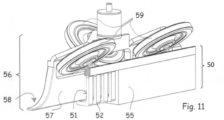
Les figures 10 et 11 illustrent un rail de guidage 50 de chaussée à fente de construction continu similaire au profilé métallique 4 mais qui ne comporte pas de surface de contact 2, 3, tout en maintenant la possibilité d’être enroulé sur bobine comme le conduit 1 grâce aux découpes transversales 52 en partie basse similaire aux découpes 10. La fente non débouchante 51 de largeur L, identique à la fente 12, possède deux chanfreins 53 sur sa partie haute. Le profilé métallique 54 comporte un corps polymère 55. Le doigt de guidage 56 embarqué sur un véhicule (non représenté), qui engage le rail de guidage 50, a la forme d’une plaque rectangulaire 57 avec des becs 58 aux deux extrémités pour éjecter tout débris tombé dans la fente 51. Trois roues inclinées 59 sont fixées sur la plaque 57. Les roues 59 en s’appuyant sur les chanfreins 53 évitent que le corps 57 entre en contact avec le profil métallique 54 et fournissent un moyen de guidage positif sans usure sur le rail de guidage qui peut éventuellement pallier à la perte de contact visuel avec les lignes de rive d’une chaussée en conduite automatisée.Figures 10 and 11 illustrate a slotted roadway guide rail 50 of continuous construction similar to the metal profile 4 but which does not have a contact surface 2, 3, while maintaining the possibility of being wound on a coil like the conduit 1 thanks to the transverse cutouts 52 in the lower part similar to the cutouts 10. The blind slot 51 of width L, identical to the slot 12, has two chamfers 53 on its upper part. The metal profile 54 comprises a polymer body 55. The guide pin 56 on board a vehicle (not shown), which engages the guide rail 50, has the shape of a rectangular plate 57 with spouts 58 at both ends to eject any debris that has fallen into the slot 51. Three inclined wheels 59 are fixed to the plate 57. The wheels 59 resting on the chamfers 53 prevent the body 57 from coming into contact with the metal profile 54 and provide a positive guiding means without wear on the guide rail which can possibly compensate for the loss of visual contact with the edge lines of a roadway in automated driving.
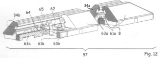
La illustre une barrette longitudinale 60 de recharge statique en courant continu selon l’invention destinée aux tramways. Le deux corps 61a et 61b de la barrette sont en polymère et comportent deux barres d’alimentation 34a et 34b, à section en T, qui de par leurs longueurs bien supérieures à celles des frotteurs du collecteur offrent une tolérance importante dans le positionnement longitudinale des frotteurs, et donc du véhicule les portant, par rapport à la barrette 60. L’alimentation de ces barres d’alimentation 34a et 34b par la source est réalisée en zone centrale par des câbles reliés aux barres par des cosses 62. En fond de cavité 8 une tôle pliée conductrice 63a court le long du fond des corps 61a et 61b et comporte des pattes latérales 63b qui servent de surface d’appui aux boulons verticaux 64 de fixation dans la chaussée, la tôle pliée conductrice 63 étant de ce fait reliée à la terre. Les cosses 61 sont protégées par un capot 65.There illustrates a longitudinal strip 60 of direct current static recharging according to the invention intended for trams. The two bodies 61a and 61b of the bar are made of polymer and comprise two supply bars 34a and 34b, with a T-section, which by their lengths much greater than those of the collector shoes offer a large tolerance in the longitudinal positioning of the shoes, and therefore of the vehicle carrying them, with respect to bar 60. The supply of these supply bars 34a and 34b by the source is carried out in the central zone by cables connected to the bars by lugs 62. At the bottom of cavity 8 a conductive bent plate 63a runs along the bottom of the bodies 61a and 61b and has lateral lugs 63b which serve as a bearing surface for the vertical bolts 64 for fixing in the roadway, the conductive bent plate 63 being thereby connected To the earth. Terminals 61 are protected by a cover 65.
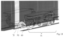
La illustre un tramway équipé du collecteur 70 fixé sur le châssis du boggie central 71 engagé dans une barrette 60 pour effectuer des charges rapides à chaque station permettant de limiter la taille des batteries de traction.There illustrates a tram equipped with the collector 70 fixed to the frame of the central bogie 71 engaged in a bar 60 to carry out rapid charges at each station making it possible to limit the size of the traction batteries.
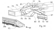
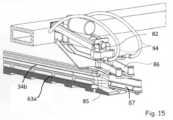
Les figures 14 et 15 illustrent un collecteur 70 pour tramway en position repliée pendant le trajet entre stations ( ) et qui s’abaisse ( ) à l’approche des stations. Le collecteur 70 comprend un mécanisme à parallélogramme déformable pour rétracter verticalement le porte frotteur 72 au-dessus de la garde au sol. Le bras supérieur 73 est articulé sur l’axe 74 sur le support 75 fixé au châssis du boggie 71. A l’autre extrémité du bras supérieur 73 un support auxiliaire 76 est articulé sur l’axe 77. Le bras inférieur 78 est articulé sur l’axe 79 avec le support 75 et sur l’axe 80 avec le support auxiliaire 76 pour fermer le parallélogramme déformable. Le corps 81 du vérin d’actuation est attaché au support 75. Un axe transversal 83 (masqué) fixé perpendiculairement sur la tige du vérin d’actuation 82 coulisse dans une lumière solidaire (masqué) et parallèle au bras supérieur 73, permettant ainsi au porte frotteur 72 de se relever en cas d’impact avec un obstacle sur la voie même si le vérin se trouve en position abaissée. Le support auxiliaire 76 comporte un bloc d’élastomère isolant 84 sur lequel sont articulés verticalement les bras conducteurs 85 et 86 qui forment un parallélogramme déformable horizontale permettant une tolérance d’alignement latéral entre la barrette 60 et le porte frotteur 72. Les frotteurs 87 (visible) et 88 (masqué) portent deux axes verticaux 89 et 90 pour s’attacher de façon mécanique et électrique aux barres 85 et 86. Le porte frotteur 72 en matériau isolant comporte deux roues métalliques 91 et 92 à axes horizontal montées sur ressort pour rouler sur la rampe 93 à l’entrée de la barrette 60 puis sur la tôle pliée conductrice 63a reliée à la terre. Les ressorts des roues métalliques 91 et 92 appliquent la pression adéquate entre les frotteurs 87, 88 et les barres d’alimentation 34a et 34b. Deux câbles 94 de forte section relient électriquement mais de façon flexible les barres d’alimentation 34a et 34b de la barrette 60 au bornier (non représenté) porté par le châssis du boggie central 71 par l’intermédiaire des frotteurs 87, 88 et des bras conducteurs 85 et 86. Figures 14 and 15 illustrate a tramway collector 70 in the folded position during the journey between stations ( ) and lowering ( ) when approaching stations. Collector 70 includes a deformable parallelogram mechanism for vertically retracting wiper holder 72 above ground clearance. The upper arm 73 is articulated on the axis 74 on the support 75 fixed to the frame of the bogie 71. At the other end of the upper arm 73 an auxiliary support 76 is articulated on the axis 77. The lower arm 78 is articulated on the axis 79 with the support 75 and on the axis 80 with the auxiliary support 76 to close the deformable parallelogram. The body 81 of the actuation cylinder is attached to the support 75. A transverse axis 83 (hidden) fixed perpendicularly to the rod of the actuation cylinder 82 slides in an integral slot (hidden) and parallel to the upper arm 73, thus allowing the wiper door 72 to rise in the event of impact with an obstacle on the track even if the cylinder is in the lowered position. The auxiliary support 76 comprises an insulating elastomer block 84 on which are vertically articulated the conductive arms 85 and 86 which form a horizontal deformable parallelogram allowing a lateral alignment tolerance between the bar 60 and the wiper holder 72. The wipers 87 ( visible) and 88 (hidden) carry two vertical axes 89 and 90 to attach mechanically and electrically to the bars 85 and 86. The wiper holder 72 made of insulating material comprises two metal wheels 91 and 92 with horizontal axes mounted on spring roll on the ramp 93 at the entrance of the bar 60 then on the conductive folded plate 63a connected to the ground. The springs of the metal wheels 91 and 92 apply the correct pressure between the wipers 87, 88 and the supply bars 34a and 34b. Two large-section cables 94 electrically but flexibly connect the supply bars 34a and 34b of the strip 60 to the terminal block (not shown) carried by the frame of the central bogie 71 via the contact shoes 87, 88 and the arms conductors 85 and 86.
La illustre un véhicule léger 99 équipé d’un collecteur compact 100, de charge statique, replié approchant une barrette 120 de recharge statique à capacité de capture latérale augmentée par rapport à la barrette 60 comprenant un corps polymère 121. Les connexions électriques avec la source sont masquées par un capot 132.There illustrates a light vehicle 99 equipped with a compact static charge collector 100, folded approaching a static recharging strip 120 with increased lateral capture capacity compared to the strip 60 comprising a polymer body 121. The electrical connections with the source are hidden by a cover 132.
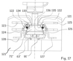
La illustre, en vue de face, la barrette de recharge statique 120, câblée en courant alternatif mono/triphasé, reprenant la configuration de la barrette 60 décrite à la câblée en courant continu. Comme pour la barrette 60, le corps 121 a deux encoches 122 en T pour recevoir les barres d’alimentation 34a, 34b en courant continu qui dans le cas d’une alimentation en courant alternatif, comprennent deux conducteurs accouplés deux par deux 123-124, 125-126 par un matériau isolant en noir, ces quatre conducteurs étant reliés aux 3 phases et au neutre de la source AC. Le porte frotteur 72’ similaire au porte frotteur 72 des figures 14 et 15 comporte quatre frotteurs 133 (masqué), 134(masqué), 135 et 136 ainsi que deux contacts latéraux « CP » 137 et « PP » 138 (masqué), connus pour permettre un échange d’information entre véhicule et source, reliés aux tôles de contact 127, 128 et maintenues dans le corps 121 dans des encoches en L. Comme pour la barrette 72 une tôle pliée conductrice 63’, reliée à la terre, sert de surface de roulement aux roues 91’ et 92’ (masquée) montée sur ressort qui exerce la pression adéquate entre les frotteurs 133, 134, 135 et 136 et les barres métalliques 123-124, 125-126. There illustrates, in front view, the static charging strip 120, wired with single/three-phase alternating current, taking up the configuration of the strip 60 described in DC wired. As for the bar 60, the body 121 has two T-shaped notches 122 to receive the direct current supply bars 34a, 34b which, in the case of an alternating current supply, comprise two conductors coupled two by two 123-124 , 125-126 by an insulating material in black, these four conductors being connected to the 3 phases and to the neutral of the AC source. The wiper holder 72 'similar to the wiper holder 72 of Figures 14 and 15 comprises four wipers 133 (masked), 134 (masked), 135 and 136 as well as two side contacts "CP" 137 and "PP" 138 (masked), known to allow an exchange of information between vehicle and source, connected to the contact plates 127, 128 and held in the body 121 in L-shaped notches. rolling surface to the wheels 91' and 92' (hidden) mounted on a spring which exerts the appropriate pressure between the wipers 133, 134, 135 and 136 and the metal bars 123-124, 125-126.
La illustre le collecteur compact 100 en position déployée, qui comprend un mécanisme à quatre barres inversé pour élever verticalement le porte frotteur 72’ au-dessus de la garde au sol tout en réduisant l’encombrement longitudinal « l » du collecteur par rapport au collecteur 70. Le collecteur 100 possède un châssis 101 fixé latéralement par les attaches 102 sur un longeron (non représenté) du véhicule 99. Le bras supérieur 103 de grande longueur est attaché sur le châssis 101 par l’articulation 104, son autre extrémité étant fixée à un genou 105 par l’articulation 106. La deuxième barre du mécanisme 107 est plus courte et attachée sur le châssis par l’articulation 108 et sur le genou 105 par l’articulation 109. Un corps de vérin 110 est articulé sur le châssis 101 (masqué) et la tige du vérin 111 possède une lumière 112 dans laquelle coulisse un axe 113 fixé sur le bras supérieur 103. Cette lumière 112 permet ainsi au porte-frotteur 72’ de se relever en cas d’impact d’un obstacle avec la face 114 du genou 105 même si le vérin 110-111 se trouve en position étendue.There illustrates the compact manifold 100 in the deployed position, which includes an inverted four-bar mechanism to vertically elevate the wiper carrier 72' above ground clearance while reducing the longitudinal bulk "l" of the manifold relative to the manifold 70 The collector 100 has a frame 101 fixed laterally by the attachments 102 on a side member (not shown) of the vehicle 99. The upper arm 103 of great length is attached to the frame 101 by the articulation 104, its other end being fixed to a knee 105 by the articulation 106. The second bar of the mechanism 107 is shorter and attached to the frame by the articulation 108 and to the knee 105 by the articulation 109. A cylinder body 110 is articulated on the frame 101 (hidden) and the cylinder rod 111 has a slot 112 in which a pin 113 fixed to the upper arm 103 slides. the face 114 of the knee 105 even if the actuator 110-111 is in the extended position.
Les figures 19, 20 et 21 illustrent un camion 139 équipé d’un collecteur dynamique 140, selon l’invention, engagé dans le conduit 1’. Le collecteur 140 est monté sur un rail transversal 141 disposé de façon avantageuse à l’avant du camion 139. Le collecteur 140 comprend un butoir 142 et des carénages 143a, 143b de part et d’autre pour en diminuer la trainée. Sur la , le collecteur 140 engage un conduit 1’ dont la surface supérieure affleure la surface de la chaussée tandis que la illustre le même collecteur 140 engagé dans un conduit 1’ qui est inséré dans un coussin 145 comportant des orifices latéraux 146 pour l’écoulement des eaux pluviales et débris de dimensions supérieures à la largeur de la fente 12 de largeur « L ». Ceci représente un avantage substantiel de l’invention qui permet de fonctionner avec des conduits 1, 1’ placés dans une rainure de chaussée ou sur la chaussée. De ce fait on pourra réaliser des portions de route ou alternativement le conduit 1, 1’ se trouve en saillie ou dans la chaussée, par exemple pour les zones de travaux sur l’autoroute où il est nécessaire temporairement de modifier l’emplacement latéral de la voie sans qu’il soit nécessaire de mettre en place une rainure apte à gérer les eaux pluviales.Figures 19, 20 and 21 illustrate a truck 139 equipped with a dynamic collector 140, according to the invention, engaged in the pipe 1'. Collector 140 is mounted on a transverse rail 141 advantageously disposed at the front of truck 139. Collector 140 comprises a stopper 142 and fairings 143a, 143b on either side to reduce drag. On the , the manifold 140 engages a duct 1' whose upper surface is flush with the surface of the roadway while the illustrates the same collector 140 engaged in a conduit 1' which is inserted in a cushion 145 comprising side orifices 146 for the flow of rainwater and debris of dimensions greater than the width of the slot 12 of width "L". This represents a substantial advantage of the invention which makes it possible to operate with conduits 1, 1' placed in a roadway groove or on the roadway. As a result, portions of the road can be made where, alternatively, the conduit 1, 1' is projecting or in the roadway, for example for work areas on the motorway where it is temporarily necessary to modify the lateral location of the track without the need to install a groove capable of managing rainwater.
La illustre les détails en coupe du conduit 1’ qui diffère quelque peu du conduit 1 à conducteur rigides 5, 6, 7 par une cavité élargie 8’, un profilé métallique 4b ayant une forme en V à la partie basse, des câbles d’alimentation à fils compactés 5’ et 6’ dont l’isolant 26’ sert d’ancrage aux surface de contact 2’, 3’.There illustrates the sectional details of conduit 1' which differs somewhat from conduit 1 with rigid conductors 5, 6, 7 by an enlarged cavity 8', a metal profile 4b having a V shape at the bottom, power cables with compacted wires 5' and 6', the insulation 26' of which serves as an anchor for the contact surface 2', 3'.
Les figures 22 et 23 illustrent le collecteur 140 en phase d’approche à l’engagement dans la fente 8’ où les roues 147a et 147b, en contact avec la chaussée, supportent le poids du collecteur 140 qui se déplace latéralement sur le charriot 148 coulissant sur le rail 141. Ce déplacement, tout en roulant est obtenu par l’action du moteur/encodeur 149 agissant sur la courroie 150 connectée au charriot 148. De même si le camion change de file de circulation, la partie avant 151 du bras supérieur 152 rentre en contact avec les butées inclinées 153a et 153b fixées sur le rail 141 provoquant mécaniquement le relèvement du collecteur 140.Figures 22 and 23 illustrate the collector 140 in the approach phase to engagement in the slot 8 'where the wheels 147a and 147b, in contact with the roadway, support the weight of the collector 140 which moves laterally on the trolley 148 sliding on the rail 141. This movement, while rolling is obtained by the action of the motor/encoder 149 acting on the belt 150 connected to the trolley 148. Similarly if the truck changes traffic lane, the front part 151 of the arm upper 152 comes into contact with the inclined stops 153a and 153b fixed on the rail 141 mechanically causing the raising of the collector 140.
Les figures 24 et 25 illustrent le collecteur 140 en détails avec le parallélogramme déformable vertical constitué par le bras supérieur 152 articulé sur le chariot 148 sur l’axe 157, et le bras inférieur 154 également articulé sur le chariot 148, ces deux bras étant connectés en parallélogramme au châssis 162 portant la roue 147b. La roue 147a est montée sur le butoir 142 qui coulisse dans le châssis 162 grâce aux lumières 164a et pions 164b. Le butoir est maintenu en position avancée par les ressorts 165. Une roue 155 comportant un boudin central est portée par un support 156 articulé sur l’axe de la roue 147b. Lorsque le collecteur roule sur les roues 147a et 147b avant d’engager la fente 8, la gravité maintient la roue 155 en position basse et par l’intermédiaire du palonnier 159 et des biellettes 172a et 172b les porte-frotteurs 171a et 171b, articulés sur le châssis 162 sur l’axe longitudinal 163, maintiennent les frotteurs 160a et 160b verticaux dans le volume extrudé longitudinalement des roues 147a et 147b comme on peut le voir sur la . Lorsque les roues 147a et 147b tombent dans la fente 8, la roue 155 entre en contact avec la face supérieure du conduit 1’ ce qui pousse la roue 155 en position haute et par action sur les biellettes 172a 172b, les porte-frotteurs 171a et 171b basculent les frotteurs 160a et 160 b sur l’axe de basculement 163 pour les mettre en contact avec les surfaces de contact 2 ‘ et 3’ du conduit 1’. De façon à appliquer une pression constante sur les frotteurs, les biellettes 172a et 172b ne sont pas connectées directement sur les porte-frotteurs 171a et 171b mais aux poussoirs 174a et 174b articulés sur l’axe de basculement 163 qui appliquent par l’intermédiaire des ressorts 176a et 176b une pression constante sur les porte-frotteurs 171a et 171b. Les câbles 166 connectent électriquement les frotteurs 160a et 160b au chariot 148.Figures 24 and 25 illustrate the collector 140 in detail with the vertical deformable parallelogram formed by the upper arm 152 articulated on the carriage 148 on the axis 157, and the lower arm 154 also articulated on the carriage 148, these two arms being connected in parallelogram to the frame 162 carrying the wheel 147b. The wheel 147a is mounted on the stopper 142 which slides in the frame 162 thanks to the slots 164a and pins 164b. The stopper is held in the forward position by the springs 165. A wheel 155 comprising a central flange is carried by a support 156 articulated on the axis of the wheel 147b. When the collector rolls on the wheels 147a and 147b before engaging the slot 8, gravity keeps the wheel 155 in the low position and via the lifter 159 and the rods 172a and 172b the wiper holders 171a and 171b, articulated on the frame 162 on the longitudinal axis 163, maintain the vertical shoes 160a and 160b in the longitudinally extruded volume of the wheels 147a and 147b as can be seen in the . When the wheels 147a and 147b fall into the slot 8, the wheel 155 comes into contact with the upper face of the duct 1' which pushes the wheel 155 into the high position and by action on the rods 172a 172b, the wiper holders 171a and 171b tilt the wipers 160a and 160b on the tilting axis 163 to bring them into contact with the contact surfaces 2' and 3' of the duct 1'. In order to apply a constant pressure on the wipers, the rods 172a and 172b are not connected directly to the wiper holders 171a and 171b but to the pushers 174a and 174b articulated on the tilting axis 163 which apply via the springs 176a and 176b a constant pressure on the wiper holders 171a and 171b. Cables 166 electrically connect wipers 160a and 160b to carriage 148.
Lorsqu’un obstacle heurte le butoir 142, les ressorts 165 se compriment et la partie AR du butoir 142 en forme de coin (non représentée) prend appui sur les surfaces inclinées 177a et 177b du support 156 et déplace la roue 155 en position basse ce qui conjointement relève le châssis 162 du collecteur 140 et fait basculer en position verticale les frotteurs 160a et 160b. When an obstacle hits the stopper 142, the springs 165 compress and the rear part of the wedge-shaped stopper 142 (not shown) bears on the inclined surfaces 177a and 177b of the support 156 and moves the wheel 155 into the low position. which jointly raises the frame 162 of the collector 140 and tilts the wipers 160a and 160b into the vertical position.
En fin de course du butoir 142 lorsque les pions 164b arrivent en bout de course des lumières 164a, le bras 178 du butoir 142 tire sur la bielle 179 ce qui libère la bague 180 de la tige de vérin 181 par un moyen connu de billes/gorges et les ressorts 183 relèvent instantanément le collecteur pour éviter l’obstacle. En effet le corps du vérin 182 est attaché sur le chariot 148 et c’est la bague 180 par l’intermédiaire des pions 184 qui relève le bras supérieur 152. De nouveau ces pions 184 coulissent dans des lumières 185 du bras supérieur 152 pour permettre au bras supérieur de se relever en cas d’impact d’un obstacle avec le butoir 142 même si le vérin 182-181 se trouve en position rentrée. At the end of the travel of the stopper 142 when the pins 164b arrive at the end of the travel of the slots 164a, the arm 178 of the stopper 142 pulls on the connecting rod 179 which releases the ring 180 from the cylinder rod 181 by a known means of balls / grooves and springs 183 instantly raise the collector to avoid the obstacle. Indeed the body of the cylinder 182 is attached to the carriage 148 and it is the ring 180 via the pins 184 which raises the upper arm 152. Again these pins 184 slide in slots 185 of the upper arm 152 to allow the upper arm to rise in the event of impact from an obstacle with the stopper 142 even if the jack 182-181 is in the retracted position.
La illustre la possibilité d’alimenter en basse tension le système du déposant décrit dans la demande PCT/IB2021/051187, qui a fait l'objet d'une publication WO 2021/161247, en plaçant dans la rampe 190 un conduit 1’’ selon l’invention. There illustrates the possibility of supplying low voltage to the applicant's system described in application PCT/IB2021/051187, which was the subject of publication WO 2021/161247, by placing in ramp 190 a 1" conduit according to the invention.
On remarquera que la position du collecteur 140 sur le rail transversal est fourni par le moteur/encodeur 149 et en disposant le collecteur 140 à l’avant du véhicule, les informations fournies par l’encodeur permettent, en conduite hautement automatisée, de contrôler la direction du véhicule même en cas de pertes de repère visuel des lignes de rive par temps de pluie, de nuit ou neige apportant un niveau de sécurité supplémentaire aux systèmes de conduite automatisée. Par ailleurs le doigt de guidage 56 qui peut fonctionner sur le conduit 1, 1’ ou le rail de guidage 50 peut être monté, de façon rétractable, en parallèle sur le rail 141 de part et d’autre du collecteur 140 pour permettre une automatisation plus poussée de la conduite notamment lors des changements de direction en permettant par l’engagement d’une courte section de rail de guidage 50 se trouvant à droite ou à gauche du conduit principale 1, 1’ de prendre une branche à gauche ou à droite de l’autoroute ou voie rapide, ou de prendre une sortie vers un hub logistique ou un parking de repos en cas d’assoupissement. Ce doigt de guidage 56 en coopérant avec le rail 50 peut également sécuriser le déplacement de navettes sans chauffeur en zone urbaine ou périurbaine, la barrette 60 de recharge statique aux arrêts étant placée parallèlement et à une distance fixe du rail 50.It will be noted that the position of the collector 140 on the transverse rail is provided by the motor/encoder 149 and by placing the collector 140 at the front of the vehicle, the information provided by the encoder makes it possible, in highly automated driving, to control the direction of the vehicle even in the event of loss of visual reference of the edge lines in rainy, night or snowy weather, providing an additional level of safety for automated driving systems. Furthermore the guide finger 56 which can operate on the conduit 1, 1 'or the guide rail 50 can be mounted, in a retractable manner, in parallel on the rail 141 on either side of the collector 140 to allow automation more thrust of the pipe, in particular during changes of direction, by allowing by the engagement of a short section of guide rail 50 located to the right or to the left of the main pipe 1, 1 'to take a branch to the left or to the right from the motorway or expressway, or to take an exit towards a logistics hub or a parking lot in the event of drowsiness. This guide finger 56 by cooperating with the rail 50 can also secure the movement of driverless shuttles in urban or peri-urban areas, the bar 60 for static charging at the stops being placed parallel to and at a fixed distance from the rail 50.
La présente invention permet la charge dynamique des véhicules électriques dans le but d’offrir une solution pour permettre la réduction de la taille des batteries, notamment celles des poids lourds par un facteur de 3 à 5 avec un impact sur le poids, le coût, la nécessité de renforcer le véhicule de conception thermique et l’impact environnemental qu’impose à ce jour la taille des batteries de dernière génération sur l’électro mobilité sans recharge dynamique.The present invention allows the dynamic charging of electric vehicles with the aim of offering a solution to allow the reduction of the size of the batteries, in particular those of heavy goods vehicles by a factor of 3 to 5 with an impact on the weight, the cost, the need to strengthen the thermal design vehicle and the environmental impact imposed to date by the size of the latest generation batteries on electromobility without dynamic charging.
Il va de soi que les dispositifs selon l'invention peuvent être adaptés à d’autres configurations de connexion et les exemples que l'on vient de donner ne sont que des illustrations particulières en aucun cas limitatives des domaines d'application de l'invention.It goes without saying that the devices according to the invention can be adapted to other connection configurations and the examples which have just been given are only particular illustrations in no way limiting the fields of application of the invention. .
Claims (15)
- Dispositif d’alimentation électrique de véhicules à propulsion électrique comportant, une ou plusieurs batteries de traction, au moins un collecteur de courant (70, 100, 140) embarqué sur lesdits véhicules et au moins un conduit fixe (1, 1’, 1’’) d’alimentation par le sol sensiblement parallèle à la direction du déplacement desdits véhicules, comportant une fente verticale (12), débouchant dans une cavité (8, 8’) dudit conduit pour recevoir ledit collecteur de courant (70, 100, 140), ladite cavité (8, 8’) contenant au moins une surface de contact électrique (2, 2’, 3, 3’, 123, 124, 125, 126) reliée à une source fixe de courant par un câble d’alimentation (5, 5’, 6, 6’), ladite surface de contact (2, 2’, 3, 3’, 123, 124, 125, 126) se trouvant en retrait d’un accès direct par ladite fente (12), caractérisé en ce que ladite surface de contact électrique est positionnée dans ladite cavité (8, 8’) dudit conduit (1, 1’, 1’’) en corniche inclinée.Device for supplying electrically powered vehicles comprising one or more traction batteries, at least one current collector (70, 100, 140) on board said vehicles and at least one fixed conduit (1, 1', 1' ') ground supply substantially parallel to the direction of movement of said vehicles, comprising a vertical slot (12), opening into a cavity (8, 8') of said conduit to receive said current collector (70, 100, 140 ), said cavity (8, 8') containing at least one electrical contact surface (2, 2', 3, 3', 123, 124, 125, 126) connected to a fixed current source by a power cable (5, 5', 6, 6'), said contact surface (2, 2', 3, 3', 123, 124, 125, 126) being set back from direct access by said slot (12) , characterized in that said electrical contact surface is positioned in said cavity (8, 8') of said conduit (1, 1', 1'') as an inclined cornice.
- Dispositif selon la revendication 1, caractérisé en ce que ledit conduit (1, 1’, 1’’) est de longueur excédant les limites du transport routier, ledit conduit comportant au moins un corps polymère (9) permettant l’enroulement dudit conduit sur bobine (21) de dimensions inférieures au gabarit routier.Device according to Claim 1, characterized in that the said conduit (1, 1', 1'') is of a length exceeding the limits of road transport, the said conduit comprising at least one polymer body (9) allowing the winding of the said conduit on coil (21) of dimensions smaller than the road gauge.
- Dispositif selon la revendication 1, caractérisé en ce que ledit conduit (1, 1’, 1’’) est installé dans une rainure (15) fraisée dans la chaussée (16), la surface supérieure dudit conduit (1, 1’) affleurant ladite chaussée (16).Device according to Claim 1, characterized in that the said conduit (1, 1', 1'') is installed in a groove (15) milled in the pavement (16), the upper surface of the said conduit (1, 1') being flush said roadway (16).
- Dispositif selon la revendication 1, caractérisé en ce que ledit conduit (1, 1’, 1’’) est positionné sur ladite chaussée (16) ou dans le coussin (145) de part et d’autre du conduit présentant une surface transversale, rattrapant le niveau de ladite chaussée (16), en pente douce.Device according to Claim 1, characterized in that the said conduit (1, 1', 1'') is positioned on the said roadway (16) or in the cushion (145) on either side of the conduit having a transverse surface, catching up with the level of said road (16), gently sloping.
- Dispositif selon la revendication 1, caractérisé en ce que le corps (9) en polymère est renforcé par au moins un profilé métallique (4, 4a, 4b) continu ouvert au niveau de ladite fente (12). Device according to Claim 1, characterized in that the body (9) made of polymer is reinforced by at least one continuous metal section (4, 4a, 4b) open at the level of the said slot (12).
- Dispositif selon la revendication 1, caractérisé en ce que ladite surface de contact (2, 2’, 3, 3’, 123, 124, 125, 126) présente sur sa face débouchant dans la cavité un faible coefficient de friction et une bonne résistance à l’abrasion par des moyens connus et en ce que la connexion électrique se fait sur la face opposée par contact latéral direct avec ledit câble d’alimentation (5, 5’, 6, 6’). Device according to Claim 1, characterized in that the said contact surface (2, 2', 3, 3', 123, 124, 125, 126) has on its face opening into the cavity a low coefficient of friction and good resistance. abrasion by known means and in that the electrical connection is made on the opposite face by direct lateral contact with said power cable (5, 5', 6, 6').
- Dispositif selon la revendication 5 caractérisé en ce que ledit conduit (1, 1’, 1’’) comprenant ledit profile métallique (4, 4a, 4b) et câbles d’alimentation (5, 5’, 6, 6’) est :
- fléchi plastiquement en sortie de chaine de fabrication pour s’enrouler sur ladite bobine de transport (21) et
- redressé lors de ladite installation dans ou sur ladite chaussée (16).
- plastically bent at the end of the production line to be wound on said transport reel (21) and
- straightened upon said installation in or on said roadway (16).
- Dispositif selon la revendication 7, caractérisé en ce que le redressage lors de la pose se fait par un dispositif de rouleuse à galets cintreuse (23).Device according to Claim 7, characterized in that the straightening during laying takes place by means of a bending roller device (23).
- Dispositif selon la revendication 5, caractérisé en ce que ledit profilé métallique (4, 4a, 4b) comporte des découpes transversales partielles (10, 10’) réduisant son inertie en flexion dans le plan de ladite fente (12).Device according to Claim 5, characterized in that the said metal profile (4, 4a, 4b) comprises partial transverse cutouts (10, 10') reducing its bending inertia in the plane of the said slot (12).
- Dispositif selon la revendication 1, caractérisé en ce que ladite fente (12) a une largeur inférieure à la norme de sécurité prévenant la pénétration d’un doigt dans la fente (12) fixée actuellement à 12 mm en Europe (IEC 60529).Device according to claim 1, characterized in that said slot (12) has a width less than the safety standard preventing the penetration of a finger into the slot (12) currently fixed at 12 mm in Europe (IEC 60529).
- Dispositif selon la revendication 10, caractérisé en ce que les bordures de ladite fente (12) sont métalliques et reliées électriquement à la « terre » et ont une hauteur égale ou supérieur à la largeur de la fente, la roue à boudin (55), ou les roues inclinées (59) ayant une bande de roulement en polymère conducteur.Device according to Claim 10, characterized in that the edges of the said slot (12) are metallic and electrically connected to the "earth" and have a height equal to or greater than the width of the slot, the flanged wheel (55), or the inclined wheels (59) having a conductive polymer tread.
- Dispositif selon la revendication 11, caractérisé en ce que ledit câble d’alimentation (5, 5’, 6, 6’) est en aluminium électriquement connecté à la surface de contact conductrice (2, 2’, 3, 3’) et que ladite surface de contact présente des découpes partielles (13, 13’) réduisant l’inertie en flexion dans le plan de ladite fente (12).Device according to claim 11, characterized in that said power cable (5, 5', 6, 6') is made of aluminum electrically connected to the conductive contact surface (2, 2', 3, 3') and that said contact surface has partial cutouts (13, 13') reducing the bending inertia in the plane of said slot (12).
- Dispositif selon la revendication 10, caractérisé en ce que le conduit (1, 1’) est alimenté en courant continu et comporte dans ladite cavité (8, 8’) au moins deux surfaces de contact électrique (2, 2’, 3, 3’) positionnées en corniche inclinée, de part et d’autre de ladite fente (12), l’une (2, 2’) étant alimentée en basse tension inférieure au neutre et l’autre (3, 3’) en basse tension supérieure au neutre.Device according to Claim 10, characterized in that the conduit (1, 1') is supplied with direct current and comprises in the said cavity (8, 8') at least two electrical contact surfaces (2, 2', 3, 3 ') positioned on an inclined ledge, on either side of said slot (12), one (2, 2') being supplied with low voltage below neutral and the other (3, 3') with low voltage higher than neutral.
- Dispositif selon la revendication 10, caractérisé en ce que ledit collecteur de courant (140) comporte au moins un frotteur conducteur (160a, 160b) pouvant basculer après introduction verticale dans ladite cavité (8, 8’), l’axe de basculement (163) étant situé en dessous de la face supérieure dudit conduit (1, 1’, 1’’).Device according to Claim 10, characterized in that the said current collector (140) comprises at least one conductive shoe (160a, 160b) capable of tilting after vertical introduction into the said cavity (8, 8'), the tilting axis (163 ) being located below the upper face of said duct (1, 1', 1'').
- Dispositif selon la revendication 10, caractérisé en ce que ledit conduit (1, 1’) comporte à la base de ladite cavité des orifices (11a, 11b, 146) d’évacuation d’eau pluviale et débris de dimensions supérieures à la largeur de ladite fente (12).Device according to Claim 10, characterized in that the said conduit (1, 1') comprises at the base of the said cavity orifices (11a, 11b, 146) for the evacuation of rainwater and debris of dimensions greater than the width of the said slot (12).
Applications Claiming Priority (2)
| Application Number | Priority Date | Filing Date | Title |
|---|---|---|---|
| FR2111004A FR3128415A1 (en) | 2021-10-18 | 2021-10-18 | Safe "low voltage" conductive connection device to the ground for static and dynamic load. |
| FRFR2111004 | 2021-10-18 |
Publications (1)
| Publication Number | Publication Date |
|---|---|
| WO2023067496A1 true WO2023067496A1 (en) | 2023-04-27 |
Family
ID=83995425
Family Applications (1)
| Application Number | Title | Priority Date | Filing Date |
|---|---|---|---|
| PCT/IB2022/059996 WO2023067496A1 (en) | 2021-10-18 | 2022-10-18 | Safe low-voltage conductive ground-installed connecting device for statically and dynamically charging electric vehicles |
Country Status (2)
| Country | Link |
|---|---|
| FR (1) | FR3128415A1 (en) |
| WO (1) | WO2023067496A1 (en) |
Citations (7)
| Publication number | Priority date | Publication date | Assignee | Title |
|---|---|---|---|---|
| US2068403A (en) * | 1936-06-12 | 1937-01-19 | Albin L Ekstrom | Vehicular apparatus |
| US20080105509A1 (en) * | 2004-09-30 | 2008-05-08 | Lohr Industrie | Ground Power Supply System For Electric Vehicle |
| CN102152746A (en) * | 2011-04-21 | 2011-08-17 | 郭仲秋 | Pavement charging and charged device series for electric vehicle |
| US20150041273A1 (en) * | 2013-08-06 | 2015-02-12 | Amres Network Coalition, LLC | Systems and methods for providing in-road electric conductivity boxes and on-vehicle descent and pivot contacts for vehicles |
| DE102014223940A1 (en) * | 2014-11-25 | 2016-05-25 | Robert Bosch Gmbh | Power supply system for an electric vehicle, electric vehicle and supply channel |
| US10981459B1 (en) * | 2020-10-29 | 2021-04-20 | Walter Thomas Davey, Jr. | Charging system for electric vehicles in motion |
| WO2021161247A1 (en) | 2020-02-14 | 2021-08-19 | Philippe Nobileau | Highly automated mode of road traffic |
-
2021
- 2021-10-18 FR FR2111004A patent/FR3128415A1/en active Pending
-
2022
- 2022-10-18 WO PCT/IB2022/059996 patent/WO2023067496A1/en active Search and Examination
Patent Citations (7)
| Publication number | Priority date | Publication date | Assignee | Title |
|---|---|---|---|---|
| US2068403A (en) * | 1936-06-12 | 1937-01-19 | Albin L Ekstrom | Vehicular apparatus |
| US20080105509A1 (en) * | 2004-09-30 | 2008-05-08 | Lohr Industrie | Ground Power Supply System For Electric Vehicle |
| CN102152746A (en) * | 2011-04-21 | 2011-08-17 | 郭仲秋 | Pavement charging and charged device series for electric vehicle |
| US20150041273A1 (en) * | 2013-08-06 | 2015-02-12 | Amres Network Coalition, LLC | Systems and methods for providing in-road electric conductivity boxes and on-vehicle descent and pivot contacts for vehicles |
| DE102014223940A1 (en) * | 2014-11-25 | 2016-05-25 | Robert Bosch Gmbh | Power supply system for an electric vehicle, electric vehicle and supply channel |
| WO2021161247A1 (en) | 2020-02-14 | 2021-08-19 | Philippe Nobileau | Highly automated mode of road traffic |
| US10981459B1 (en) * | 2020-10-29 | 2021-04-20 | Walter Thomas Davey, Jr. | Charging system for electric vehicles in motion |
Also Published As
| Publication number | Publication date |
|---|---|
| FR3128415A1 (en) | 2023-04-28 |
Similar Documents
| Publication | Publication Date | Title |
|---|---|---|
| EP2923882B1 (en) | System for supplying power via the ground for free-wheeled electric vehicles | |
| CA2886171C (en) | Power supply system for unguided electric vehicles through the ground and associated usage process | |
| EP0962353B1 (en) | Ground feeding system for electrical vehicle and associated vehicle | |
| EP0833759B1 (en) | Electrical power supply and guidance assembly along a ground rail for a wheeled vehicle | |
| WO2006035139A1 (en) | Ground power supply system for electric vehicle | |
| EP2552736B1 (en) | Upper lateral structure for the occasional or continuous collection of main-drive or auxiliary electrical power by a land vehicle | |
| WO2017092999A1 (en) | Recharging station for electric public transport vehicle, and facility comprising such a station | |
| FR2916696A1 (en) | TRANSIT SYSTEM, ELECTRIC VEHICLE AND REGENERATION STATION FOR THIS SYSTEM | |
| FR2920448A1 (en) | Traffic lane forming module for e.g. tramcar, has carrier structure with crosspieces that connect beams, and I-shaped rail guiding section mounted on carrier structure to guide urban transport vehicle | |
| FR2920709A1 (en) | DEVICE FOR GUIDING AND CAPTURING ELECTRICAL GROUND ENERGY FOR VEHICLE, AND URBAN TRANSPORT VEHICLE EQUIPPED WITH SUCH A DEVICE. | |
| WO2023067496A1 (en) | Safe low-voltage conductive ground-installed connecting device for statically and dynamically charging electric vehicles | |
| EP1694525B1 (en) | Device for guiding and supplying electrical power to a vehicle by a trough in the ground | |
| FR2861024A1 (en) | Electrical energy collecting device for e.g. industrial truck, has collecting blade electrically insulated from ground and path structure, and having conducting units in electrical contact sliding along polar parts carried by work holders | |
| EP4103780A1 (en) | Highly automated mode of road traffic | |
| WO2007029092A1 (en) | Automatic parking lot | |
| FR2651823A1 (en) | Car park for motor vehicles and transportation carriages provided for equipping it | |
| EP0354829A1 (en) | Automatic recording and parking mode system for vehicles, particularly in the urban area. | |
| RU2044858C1 (en) | Car parking method and device | |
| CA2084653A1 (en) | Transportation system for a motor vehicle capable of driving on conventional highway and street facilities, and on a guidance network | |
| WO2021185871A1 (en) | Heavy and/or bulky load handling kit for easy loading and unloading, intended to be integrated into a utility vehicle | |
| FR3102954A1 (en) | Automatic retraction of a current collection device in an electric vehicle | |
| FR2780685A1 (en) | Electric tramway installation without overhead wires | |
| FR2563545A1 (en) | Method for renewing railway track gear and handling equipment enabling this method to be implemented |
Legal Events
| Date | Code | Title | Description |
|---|---|---|---|
| 121 | Ep: the epo has been informed by wipo that ep was designated in this application |
Ref document number: 22793882 Country of ref document: EP Kind code of ref document: A1 |
|
| DPE1 | Request for preliminary examination filed after expiration of 19th month from priority date (pct application filed from 20040101) |