WO2023063428A1 - Multicore cable processing device - Google Patents
Multicore cable processing device Download PDFInfo
- Publication number
- WO2023063428A1 WO2023063428A1 PCT/JP2022/038481 JP2022038481W WO2023063428A1 WO 2023063428 A1 WO2023063428 A1 WO 2023063428A1 JP 2022038481 W JP2022038481 W JP 2022038481W WO 2023063428 A1 WO2023063428 A1 WO 2023063428A1
- Authority
- WO
- WIPO (PCT)
- Prior art keywords
- core
- multicore cable
- multicore
- cable
- sheath
- Prior art date
Links
- 238000012545 processing Methods 0.000 title claims abstract description 173
- 238000005520 cutting process Methods 0.000 claims abstract description 40
- 238000000034 method Methods 0.000 claims description 71
- 238000002788 crimping Methods 0.000 claims description 58
- 230000008569 process Effects 0.000 claims description 55
- 238000001514 detection method Methods 0.000 claims description 37
- 238000011144 upstream manufacturing Methods 0.000 claims description 35
- 238000009413 insulation Methods 0.000 claims description 18
- 238000005452 bending Methods 0.000 claims description 15
- 238000000926 separation method Methods 0.000 claims description 13
- 238000010438 heat treatment Methods 0.000 claims description 9
- 239000011248 coating agent Substances 0.000 claims description 8
- 238000000576 coating method Methods 0.000 claims description 8
- 238000000605 extraction Methods 0.000 claims description 6
- 239000000969 carrier Substances 0.000 claims description 5
- 238000003780 insertion Methods 0.000 claims description 4
- 230000037431 insertion Effects 0.000 claims description 4
- 125000004122 cyclic group Chemical group 0.000 claims 1
- 230000032258 transport Effects 0.000 description 49
- 238000012546 transfer Methods 0.000 description 40
- 230000002950 deficient Effects 0.000 description 14
- 230000008859 change Effects 0.000 description 4
- 239000004020 conductor Substances 0.000 description 4
- 238000003908 quality control method Methods 0.000 description 4
- 238000013459 approach Methods 0.000 description 3
- 238000010586 diagram Methods 0.000 description 2
- 239000012212 insulator Substances 0.000 description 2
- 238000004804 winding Methods 0.000 description 2
- 230000009471 action Effects 0.000 description 1
- 230000008901 benefit Effects 0.000 description 1
- 230000003028 elevating effect Effects 0.000 description 1
- 238000009434 installation Methods 0.000 description 1
- 239000002932 luster Substances 0.000 description 1
- 238000000465 moulding Methods 0.000 description 1
- 230000002093 peripheral effect Effects 0.000 description 1
- 238000003825 pressing Methods 0.000 description 1
- 239000000523 sample Substances 0.000 description 1
- 238000004904 shortening Methods 0.000 description 1
Images


Classifications
-
- B—PERFORMING OPERATIONS; TRANSPORTING
- B21—MECHANICAL METAL-WORKING WITHOUT ESSENTIALLY REMOVING MATERIAL; PUNCHING METAL
- B21F—WORKING OR PROCESSING OF METAL WIRE
- B21F1/00—Bending wire other than coiling; Straightening wire
- B21F1/02—Straightening
-
- H—ELECTRICITY
- H02—GENERATION; CONVERSION OR DISTRIBUTION OF ELECTRIC POWER
- H02G—INSTALLATION OF ELECTRIC CABLES OR LINES, OR OF COMBINED OPTICAL AND ELECTRIC CABLES OR LINES
- H02G1/00—Methods or apparatus specially adapted for installing, maintaining, repairing or dismantling electric cables or lines
- H02G1/12—Methods or apparatus specially adapted for installing, maintaining, repairing or dismantling electric cables or lines for removing insulation or armouring from cables, e.g. from the end thereof
-
- H—ELECTRICITY
- H02—GENERATION; CONVERSION OR DISTRIBUTION OF ELECTRIC POWER
- H02G—INSTALLATION OF ELECTRIC CABLES OR LINES, OR OF COMBINED OPTICAL AND ELECTRIC CABLES OR LINES
- H02G1/00—Methods or apparatus specially adapted for installing, maintaining, repairing or dismantling electric cables or lines
- H02G1/14—Methods or apparatus specially adapted for installing, maintaining, repairing or dismantling electric cables or lines for joining or terminating cables
-
- Y—GENERAL TAGGING OF NEW TECHNOLOGICAL DEVELOPMENTS; GENERAL TAGGING OF CROSS-SECTIONAL TECHNOLOGIES SPANNING OVER SEVERAL SECTIONS OF THE IPC; TECHNICAL SUBJECTS COVERED BY FORMER USPC CROSS-REFERENCE ART COLLECTIONS [XRACs] AND DIGESTS
- Y02—TECHNOLOGIES OR APPLICATIONS FOR MITIGATION OR ADAPTATION AGAINST CLIMATE CHANGE
- Y02W—CLIMATE CHANGE MITIGATION TECHNOLOGIES RELATED TO WASTEWATER TREATMENT OR WASTE MANAGEMENT
- Y02W30/00—Technologies for solid waste management
- Y02W30/50—Reuse, recycling or recovery technologies
- Y02W30/82—Recycling of waste of electrical or electronic equipment [WEEE]
Definitions
- the present invention relates to a processing device for multicore cables.
- Patent Document 1 After the sheath is removed to expose the covered wire (core wire) and the drain wire, the drain wire is bent 90 degrees to be separated from the core wire, and the drain wire is inserted into a heat-shrinkable tube. A method of insulating a drain line is disclosed. In the method disclosed in Patent Literature 1, the drain wire is then insulated by heat-shrinking the heat-shrinkable tube.
- a multi-core cable processing apparatus is an apparatus for processing a multi-core cable having a sheath and a plurality of core wires inserted through the sheath, wherein a slit is formed in the sheath along the circumferential direction. and a pulling device for exposing the plurality of core wires by moving at least one of the sheath on the tip side of the multicore cable and the sheath on the base side of the cut in the longitudinal direction of the multicore cable. a detecting device for detecting the position of a specific core wire among the plurality of core wires in the circumferential direction of the multicore cable; and rotating the multicore cable based on the detected position of the specific core wire in the circumferential direction. and a rotating device for moving the specific core wire to a predetermined position in the circumferential direction.
- the multicore cable is rotated based on the circumferential position of the specific core wire detected by the detection device, and the position of the specific core wire is changed from the predetermined circumferential position. can do. This makes it possible to identify the positions of the core wires of the multicore cable.
- the plurality of core wires are composed of a drain wire and a plurality of core wires, and the specific core wire is the drain wire.
- the multicore cable processing device urges at least one of the drain wire and the plurality of core wires based on the detected circumferential position of the drain wire, thereby separating the drain wire and the plurality of core wires.
- the processing of the multicore shielded cable up to the insulation treatment of the drain wire can be automatically performed.
- the apparatus for processing a multicore cable further includes a straightening device for straightening the separated drain wires by twisting them in the circumferential direction and applying a tensile tension before the insulation treatment. ing.
- the drain wire can be easily insulated by correcting the drain wire.
- the insulation processing apparatus includes an insertion apparatus for inserting the separated drain wire into a heat-shrinkable tube, and a and a heating device for heating the heat-shrinkable tube.
- insulation processing is performed by inserting the drain wire into the heat-shrinkable tube and heat-shrinking the heat-shrinkable tube. Therefore, compared with other methods, for example, the method of winding an insulating tape around the drain wire, it is easier to perform the insulating treatment by an automatic machine.
- the pulling device rotates the sheath on the distal end side and While rotating at least one of the sheaths on the root side, the sheath on the tip side is pulled out to untwist the plurality of core wires.
- the detection device can easily detect the position of a specific core wire.
- the pull-out device exposes a part of the plurality of core wires, and attaches the other part of the plurality of core wires to the distal end side.
- the semi-stripping of pulling out the sheath on the distal end side so that the sheath remains is performed prior to the detection of the specific core wire by the detection device.
- the extracting device is configured to perform all stripping, in which the sheath on the distal end side is detached from the plurality of core wires, after detection of the specific core wire by the detection device.
- the detection device when detecting the position of a specific core wire by the detection device, it is possible to prevent the core wires from becoming loose and making detection difficult.
- the multi-core cable processing device further includes an alignment device for aligning the plurality of core wires at predetermined intervals.
- the alignment device comprises an alignment member and a moving device.
- the alignment member has a plurality of comb teeth, and a plurality of gaps corresponding to the plurality of core wires are provided between the comb teeth.
- the moving device moves at least one of the alignment member and the multicore cable, and inserts the plurality of core wires into the plurality of gaps of the alignment member.
- the plurality of gaps are formed so as to separate from each other toward the front in the moving direction when the plurality of core wires are inserted, and are arranged at the predetermined intervals at the front end in the moving direction.
- a plurality of core wires are aligned at predetermined intervals, and their respective positions are specified. As a result, it becomes easier to process the plurality of core wires in the post-process.
- the apparatus for processing a multicore cable is configured and loaded with a plurality of gripping members each capable of gripping one of the core wires and a tip portion of the core wire. and a loading device for individually moving the plurality of gripping members and individually loading the core wires gripped by the gripping members into the stripping device.
- the core wires of multi-core cables one by one.
- the plurality of core wires are loaded into the stripping device one by one by the loading device. Therefore, the quality of the core wire strip can be ensured.
- the apparatus for processing a multicore cable further includes a crimping device configured to be loaded with the tip of the core wire and crimping a terminal to the tip of the loaded core wire. ing.
- the loading device is configured to individually move the plurality of gripping members, and individually load the core wires, which are gripped by the gripping members and whose distal ends have been stripped, into the crimping device.
- the plurality of core wires includes a plurality of core wires.
- the multi-core cable processing apparatus further includes a rubber plug mounting device configured to load the tip of the core wire and mounting a waterproof rubber plug to the loaded core wire.
- the loading device individually moves the plurality of gripping members to individually move the core wires gripped by the gripping members to the rubber plug mounting device before the coating of the tip portion of the core wire is stripped. configured to load.
- a multicore cable processing apparatus includes a processing station provided with at least one of the cutting device, the pulling device, the detecting device, and the rotating device; another processing station arranged side by side with the station in a predetermined direction and provided with at least one other of the cutting device, the pulling device, the detecting device, and the rotating device; It further comprises a first conveying device that conveys the multicore cable to the pulling device, the detecting device, and the rotating device.
- the first conveying device includes a gripping device that grips the multicore cable bent so that one end and the other end are aligned in the predetermined direction, a gripping device moving device that moves the gripping device in the predetermined direction, It has The device provided at the other processing station processes the other end of the multicore cable while the device provided at the processing station is processing the one end.
- one end and the other end of the multicore cable can be processed at the same time. Therefore, the cycle time for processing the multicore cable can be shortened.
- a multicore cable processing apparatus includes a first conveying device that conveys the multicore cable to the cutting device, the pulling device, the detecting device, and the rotating device; a stripping device configured to be loaded with a tip portion of a core wire and stripping the coating from the tip portion of the loaded core wire; It further comprises a crimping device that crimps a terminal onto the tip of the stripped core wire, and a second conveying device that conveys the multicore cable to the stripping device and the crimping device.
- the second conveying device includes a carrier having a plurality of gripping members each capable of gripping one core wire, and a carrier moving device that moves the carrier.
- the carrier moving device has a take-up position where the multi-core cable is taken, a first facing position facing the stripping device, a second facing position facing the crimping device, and the multi-core cable after the terminals are crimped. Moving the carrier to and from a release position releasing the core cable.
- the multi-core cable can be conveyed without re-grasping the core wire while stripping the core wire and crimping the terminal. Therefore, there is no fear that the position of the core wire will change due to re-grasping, and it will be stable. Thereby, stripping of the core wire and crimping of the terminal can be performed with high quality.
- the second conveying device includes a plurality of carriers.
- the carrier moving device cyclically moves the plurality of carriers.
- the carrier can be returned from the release position to the take-up position, so the multicore cable can be continuously transported. Moreover, since a plurality of carriers circulate, productivity can be improved.
- the circulatory movement of the carrier includes lateral movement between the take-up position, the first opposing position, and the second opposing position, and the take-up position.
- a cyclical movement including vertical movement between a position, the first opposed position, and a position below the second opposed position.
- the plurality of gripping members of the carrier grip the plurality of core wires when the carrier moves from a position below the take-up position to the take-up position.
- the core wires can be gripped by utilizing the vertical movement during the circulating movement of the carrier, so the process time can be shortened.
- the multicore cable processing apparatus includes a plurality of processing stations provided with one or more of the cutting device, the pulling device, the detecting device, and the rotating device. ing.
- the first conveying device includes a plurality of stationary gripping devices provided to face the plurality of processing stations and gripping the multicore cable, and a plurality of fixed gripping devices configured to grip the multicore cable, respectively. and one or more moving grippers that reciprocate between two adjacent fixed grippers among the fixed grippers.
- the cutting device, the pulling device, the detecting device, and the rotating device which do not require advanced positioning for transporting the multicore shielded cable, use the first conveying device as the multicore cable.
- carry cables Since the first conveying device re-grips the multi-core cable between the moving gripping device and the fixed gripping device, it is difficult to achieve high positional accuracy for each core wire, but the structure is simple.
- a second transport device that does not change grips of the multicore cable transports the multicore cable. Therefore, according to the multicore cable processing apparatus, the processing quality of the multicore cable can be improved while simplifying the processing apparatus as a whole.
- the multicore cable processing apparatus further includes a delivery device that receives the multicore cable from the first transport device and delivers the multicore cable to the second transport device. .
- the multicore cable processing apparatus since the multicore cable is not directly transferred from the first transporting device to the second transporting device, the waiting time of the first transporting device and the second transporting device can be reduced. can. Therefore, it is possible to smoothly transfer the multicore cable from the first conveying device to the second conveying device.
- the plurality of processing stations are arranged side by side in the conveying direction of the multicore cable by the moving gripping device.
- the multicore cable processing apparatus further includes a bending device arranged upstream in the conveying direction from the plurality of processing stations and bending the multicore cable into a substantially U shape so that both ends are aligned in the conveying direction.
- Each of the plurality of fixed gripping devices is configured to grip one end of the multicore cable bent by the bending device.
- the device provided in each of the processing stations is capable of processing the downstream end of the bent multicore cable while the device provided in the processing station adjacent to the upstream side is processing the upstream end of the bent multicore cable. to process.
- one end and the other end of the multicore cable can be processed at the same time. Therefore, the cycle time for processing the multicore cable can be shortened.
- the plurality of gripping members of the carrier are arranged such that the plurality of core wires exposed at the end of the bent multicore cable on the upstream side. and an upstream group that is arranged downstream of the upstream group in the conveying direction and that holds the plurality of core wires exposed at the downstream end of the bent multicore cable. contains groups and
- both ends of the multicore cable bent into a substantially U shape can be gripped even by the second conveying device.
- the plurality of gripping members are configured such that the distance between both ends of the multicore cable is narrower than the distance between the ends of the multicore cable gripped by the plurality of fixed gripping devices.
- the multi-core cable is gripped.
- the processing station where the first conveying device conveys the multicore cable has a degree of freedom in arranging the devices, and the second conveying device narrows the distance between both ends of the multicore cable.
- the length of the processing apparatus in the conveying direction can be shortened.
- the multicore cable processing apparatus further includes a delivery device that receives the multicore cable from the first transport device and delivers the multicore cable to the second transport device.
- the transfer device includes a pair of gripping members that grip both ends of the multicore cable, and a driving device.
- the driving device moves the pair of gripping members toward or away from each other so that the distance between the pair of gripping members corresponds to the distance between both ends of the multicore cable when gripped by the first conveying device. or correspond to the distance between both ends of the multicore cable when it is gripped by the second transport device.
- the distance between both ends of the multicore cable is narrowed by the delivery device that delivers the multicore cable from the first transport device to the second transport device. Therefore, the device for narrowing the space between both ends of the multicore cable and the transfer device can be shared.
- the multicore cable processing apparatus of the present invention it is possible to specify the positions of the multiple core wires of the multicore cable.
- FIG. 1 is a schematic cross-sectional view of a multicore shielded cable;
- FIG. 1 is a schematic plan view of a processing apparatus for a multicore shielded cable according to one embodiment;
- FIG. 1 is a block diagram of a processing device for a multicore shielded cable;
- FIG. 4 is a schematic side view of a second station;
- FIG. 11 is a schematic plan view of a third station;
- FIG. 10 is a schematic front view of the third station, showing a state in which the core wire is separated;
- FIG. 11 is a schematic side view of a fourth station;
- FIG. 11 is a schematic side view of a fifth station;
- FIG. 11 is a schematic plan view of a sixth station;
- FIG. 11 is a schematic front view of the sixth station, showing the state in which the drain wire and the core wire are aligned;
- FIG. 11 is a schematic plan view of a seventh station;
- FIG. 11 is a schematic plan view of an eighth station;
- FIG. 11 is a schematic plan view of a ninth station;
- FIG. 3 is a rear view of a conveying device for a multicore shielded cable;
- FIG. 11 is a rear view of a conveying device for multicore shielded cables according to another embodiment;
- FIG. 1 is a schematic cross-sectional view of a multicore shielded cable 1 according to one example.
- the multicore shielded cable 1 has a sheath 2 , a drain wire 3 and a plurality of core wires 4 inserted through the sheath 2 , and a shield 5 .
- a multicore shielded cable 1 is an electric wire in which a drain wire 3 , a plurality of core wires 4 and a shield 5 are covered with a sheath 2 .
- a plurality of core lines 4 are used, for example, as signal lines for transmitting electrical signals.
- Each of the plurality of core wires 4 has a core wire 4a and an insulator covering 4b covering the core wire 4a.
- the shield 5 is a conductor that shields the core wire 4 from external noise.
- a shield 5 covers the outside of the plurality of core wires 4 .
- Drain wire 3 is electrically connected to shield 5 .
- the drain line 3 is grounded, thereby grounding the shield 5 .
- the drain wire 3 is composed of a plurality of thin conductor strands and is not covered with an insulator.
- the drain wire 3 and a plurality of core wires 4 are twisted together inside the shield 5 .
- the shield 5 is covered by an insulating sheath 2 .
- the number of core wires 4 is not particularly limited.
- the drain wire 3 and the plurality of core wires 4 are not particularly distinguished, they may be collectively referred to as core wires.
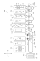
- FIG. 2 is a schematic plan view of a processing device (hereinafter simply referred to as a processing device) 200 for the multicore shielded cable 1 according to one embodiment.
- the processing device 200 is a device that insulates the drain wire 3 , crimps the terminals 8 to the ends thereof, and crimps the terminals 8 to the ends of a plurality of core wires 4 .
- the insulating treatment for the drain wire 3 is a treatment for covering the drain wire 3 with a heat-shrinkable tube 6 and heat-shrinking the heat-shrinkable tube 6 .
- the drain wire 3 and the plurality of core wires 4 are also fitted with waterproof rubber plugs 7 , but depending on the specifications of the multicore shielded cable 1 , the fitting of the rubber plugs 7 may be omitted.
- the processing apparatus 200 includes ten stations, a first station St1 to a tenth station St10.
- the multicore shielded cable 1 is conveyed between stations from the first station St1 toward the tenth station St10.
- the first station St1 to the ninth station St9 are arranged side by side in the conveying direction of the multi-core shielded cable 1 (here, the horizontal direction in FIG. 2).
- a process of measuring the length of the multicore shielded cable 1 and cutting it to a predetermined length is performed.
- the sheath 2 is cut and the sheath 2 on the distal end side is pulled out.
- the sheath 2 is not pulled out until the sheath 2 is separated from the multicore shielded cable 1, and is kept inserted into the multicore shielded cable 1. - ⁇ Further, when the sheath 2 is pulled out, the sheath 2 is rotated in the circumferential direction, and the twisted core wires of the multicore shielded cable 1 are untwisted.
- the process performed at the second station St2 is also referred to as "sheath 2 semi-stripping".
- the drain wire 3 exposed by semi-stripping the sheath 2 is detected by a camera 31a (see FIG. 5), and the drain wire 3 is positioned at a predetermined position in the circumferential direction of the multicore shielded cable 1. Rotate the multi-core shielded cable 1 as shown. Further, the sheath 2 is completely pulled out from the multicore shielded cable 1. Hereinafter, the process of completely pulling out the sheath 2 from the multicore shielded cable 1 is also referred to as "all stripping of the sheath 2".
- the drain wire 3 and the plurality of core wires 4 are separated by bending only the plurality of core wires 4 while avoiding the drain wire 3 .
- the straightening process of the drain wire 3 is performed by twisting the drain wire 3 and stretching it straight.
- the drain wire 3 is covered with the heat-shrinkable tube 6, and insulation processing is performed by heat-shrinking the heat-shrinkable tube 6.
- FIG. at the sixth station St6, the plurality of core wires 4 are bent back and aligned with the insulated drain wires 3 .
- each process does not have to be performed according to the division of the stations described above. Which process is performed at which station may be appropriately set, and is not particularly limited. Also, the order of the steps may be changed as appropriate. Furthermore, the processing apparatus 200 does not have to be installed at one place, and may be installed separately at a plurality of places. As will be described later, devices for conveying the multicore shielded cable 1 are different between the second station St2 to the sixth station St6 and the seventh station St7 and subsequent stations. Therefore, for example, the processing apparatus 200 may be divided into an apparatus including the first station St1 to the sixth station St6 and an apparatus including the seventh station St7 to the tenth station St10.
- the first station St1 to the tenth station St10 are equipped with devices for performing processing at each station.
- the first station St1 includes a feeding device 11 for conveying the multi-core shielded cable 1, a length measuring device 12 for measuring the length of the multi-core shielded cable 1, and a cutting device for cutting the multi-core shielded cable 1 to a predetermined length.
- a cutting device 13 is provided.
- a conveying device 110 is provided downstream of the first station St1 for conveying the cut multicore shielded cable 1 to each device of the second station St2 to the sixth station St6.
- the conveying device 110 includes a cutting device 21, a sheath semi-stripping device 22, a drain wire detecting device 31, a sheath stripping device 32, a core wire separating device 33, a drain wire correcting device 41, and an insulation processing device 51, all of which will be described later. , a bend-back device 61 and an alignment device 62 .
- the conveying device 110 bends the multicore shielded cable 1 into a U shape before conveying the multicore shielded cable 1 to the second station St2.
- the function of the conveying device 110 that bends the multicore shielded cable 1 into a U shape is also called a bending device 110A.
- the multicore shielded cable 1 is bent so that both ends are aligned in the direction in which the first station St1 to the ninth station St9 are arranged (horizontal direction in FIG. 2).
- both ends of the multicore shielded cable 1 face toward the stations St1 to St9 (in FIG. 2, the upward direction on the paper surface).
- the conveying device 110 includes a pair of conveying clamps 111 for gripping both ends of the multicore shielded cable 1 bent in a U shape, and the conveying clamps 111 arranged in the direction in which the first station St1 to the ninth station St9 are arranged (left and right in FIG. 2). direction).
- the second station St2 to the sixth station St6 are arranged along the moving path of the transfer clamp 111 by the clamp moving device 112 .
- the processing device 200 is a device that processes both ends of the multicore shielded cable 1 .
- a device provided at one station for example, the second station St2
- a device provided at another processing station for example, the third station St3
- Process the other end As a result, the cycle time for processing the multicore shielded cable 1 is shortened.
- a plurality of pairs of transfer clamps 111 are provided so that the multicore shielded cable 1 can be processed continuously.
- fixing clamps 130 that grip the multicore shielded cable 1 and rotate it in the circumferential direction.
- Each fixing clamp 130 also consists of a pair and grips both ends of the multi-core shielded cable 1 bent in a U shape.
- the fixed clamp 130 of each station receives and grips the multicore shielded cable 1 from the transfer clamp 111 of the transfer device 110 at the entrance of the station. After finishing the processing at each station, the fixed clamp 130 of each station delivers the multicore shielded cable 1 to the transfer clamp 111 .
- the function of the fixed clamp 130 of each station may be performed by the transfer clamp 111 to which a configuration for rotating the multicore shielded cable 1 is added.
- the second station St2 is provided with a cutting device 21 that cuts the sheath 2 and a sheath semi-stripping device 22 that semi-strips the sheath 2 .
- the third station St3 includes a drain wire detection device 31 for detecting the circumferential position of the drain wire 3, a sheath stripping device 32 for stripping the entire sheath 2, a core wire separating device 33 for separating the core wire 4, is provided. Circumferential alignment of the drain wire 3 is performed by the sheath strip device 32 and the fixing clamp 130 based on detection by the drain wire detection device 31 .
- the sheath semi-stripping device 22 and the sheath stripping device 32 may be one device provided at the same station.
- the withdrawal device for withdrawing the sheath 2 may be divided into a plurality as in the present embodiment, or may be integrated into one.
- the semi-stripping of the sheath 2 accompanies the rotation of the multicore shielded cable 1 in the circumferential direction.
- the retraction device is divided into a sheath semi-stripping device 22 , a sheath stripping device 32 and two fixed clamps 130 .
- the apparatus for performing one process may be divided into a plurality of apparatuses, or the apparatus for performing a plurality of processes may be integrated into one.
- a drain wire straightening device 41 for straightening the drain wire 3 is provided at the fourth station St4.
- the drain wire straightening device 41, the sheath semi-stripping device 22, and the sheath stripping device 32 may be one device provided at the same station.
- the above device may be divided into a plurality of devices as in this embodiment, or may be integrated into one device.
- An insulation processing device 51 is provided at the fifth station St5.
- the insulation processing device 51 includes a tube reel 52 around which a reel of the heat-shrinkable tube 6 is wound, a tube mounting device 53 that cuts the heat-shrinkable tube 6 to a predetermined length and inserts the drain wire 3 into the heat-shrinkable tube 6, and a heating device 54 for heat-shrinking the heat-shrinkable tube 6 .
- the sixth station St6 includes a bend-back device 61 for realigning the drain wire 3 and the plurality of core wires 4 separated by the core wire separating device 33, and an alignment device 62 for aligning the drain wire 3 and the plurality of core wires 4. and is provided.
- the bending-back device 61 and the alignment device 62 share a part of the configuration and are integrated.
- the bendback device 61 and the alignment device 62 may be configured separately.
- the multicore shielded cable 1 is rotated in the circumferential direction so that the drain wire 3 and the plurality of core wires 4 are aligned along the horizontal plane. This rotation process is performed by the fixed clamp 130 .
- a device 121 is provided.
- the multicore shielded cable 1 is transferred from the transfer device 110 to the shuttle 120 between the sixth station St6 and the seventh station St7.
- the seventh station St7 to tenth station St10 are arranged along the transport path of the shuttle 120 by the shuttle transport device 121 .
- there are a plurality of shuttles 120 (not shown), which circulate along a looped movement path.
- the shuttle 120 includes a plurality of individual clamps 120a that individually grip the drain wires 3 and a plurality of core wires 4, and a loading device 120b that individually approaches the plurality of individual clamps 120a to the crimping devices 91, 92, etc. there is
- a rubber plug mounting device 71 is provided at the seventh station St7.
- a core wire stripping device 81 is provided at the eighth station St8.
- a right crimping device 91 and a left crimping device 92 are provided at the ninth station St9.
- a right crimping device 91 and a left crimping device 92 are provided at the ninth station St9 because different terminals 8 may be crimped on both ends of the multicore shielded cable 1 bent into a U shape.
- the tenth station St10 is provided with a discharge tray 101 for non-defective products and a discharge tray 102 for defective products.
- the shuttle 120 separates the non-defective multi-core shielded cable 1 on the non-defective product discharge tray 101 and drops the non-defective multi-core shielded cable 1 onto the non-defective product discharge tray 101 .
- the shuttle 120 releases the defective multicore shielded cable 1 on the defective discharge tray 102 and drops the defective multicore shielded cable 1 onto the defective discharge tray 102 . Determination as to whether the product is non-defective or defective is made here at the seventh station St7 to the ninth station St9, respectively.
- the multicore shielded cable 1 determined to be defective is discharged to the discharge tray 102 for defective products without proceeding to the next process.
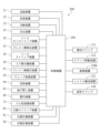
- FIG. 3 is a block diagram of the processing device 200.
- the processing device 200 includes a control device 150. As shown in FIG. The operation of each part of the processing device 200 is controlled by the control device 150 .
- the control device 150 controls the feeding device 11, the length measuring device 12, the cutting device 13, the cutting device 21, the sheath semi-stripping device 22, the drain wire detecting device 31, the sheath stripping device 32, the core wire A separation device 33, a drain wire straightening device 41, a tube mounting device 53, a heating device 54, a bend-back device 61, an alignment device 62, a rubber plug mounting device 71, a core wire stripping device 81, and a right crimping device.
- control device 150 may include, for example, a central processing unit (hereinafter referred to as a CPU), a ROM in which programs executed by the CPU are stored, and a RAM. Each part of the control device 150 may be configured by software or may be configured by hardware. Also, each unit may be a processor or a circuit. Control device 150 may be, for example, a programmable controller, a computer, or the like.
- a CPU central processing unit
- ROM read-only memory
- RAM random access memory
- Each part of the control device 150 may be configured by software or may be configured by hardware. Also, each unit may be a processor or a circuit.
- Control device 150 may be, for example, a programmable controller, a computer, or the like.
- FIG. Left and right refer to left and right as viewed forward.
- F, Rr, L, R, U, and D represent front, back, left, right, up and down, respectively.
- these directions are for convenience of explanation, and do not limit the installation mode of the processing apparatus 200 in any way.
- the path of travel of transport apparatus 110 or shuttle 120 need not be straight, and may vary forward from station to station.
- a detailed description of the steps performed at the first station St1 and the tenth station St10 will be omitted.
- FIG. 4 is a schematic side view of the second station St2.
- the second station St2 includes a cutting device 21 provided forward of the fixing clamp 130 and a sheath semi-stripping device 22 provided further forward of the cutting device 21. ing.
- the fixing clamp 130 holds the multicore shielded cable 1 substantially horizontally.
- the cutting device 21 forms cuts in the sheath 2 along the circumferential direction.
- the cutting device 21 has two or more cutting blades 21 a arranged around the multicore shielded cable 1 .
- the cutting device 21 is configured to rotate a cutting blade 21 a around the multicore shielded cable 1 .
- the cutting device 21 forms a cut in the sheath 2 by bringing the cutting blade 21a closer and rotating the multicore shielded cable 1 between the cutting blades 21a.
- the sheath semi-stripping device 22 moves the sheath 2 on the tip side of the multicore shielded cable 1 from the cut to the tip side with respect to the sheath 2 on the root side to expose the drain wire 3 and the plurality of core wires 4 .
- the semi-strip of the sheath 2 exposes a part of the drain wire 3 and the plurality of core wires 4, and the other part (here, the tip portion) of the drain wire 3 and the plurality of core wires 4 is covered with a sheath on the tip side. It is a step of pulling out the sheath 2 on the distal end side so that the sheath 2 remains.
- Semi-stripping is performed before detection of the drain wire 3 by the drain wire detection device 31 . All stripping is performed after the detection of the drain wire 3 by the drain wire detection device 31 .
- the fixing clamp 130 and the sheath semi-stripping device 22 move the sheath 2 on the tip side to the tip side of the multicore shielded cable 1 while rotating it in the circumferential direction with respect to the sheath 2 on the root side in the semi-stripping process.
- the multicore shielded cable 1 including the sheath 2 on the root side is gripped and rotated by the fixing clamp 130 , and the sheath 2 on the tip side is moved to the tip side by the sheath semi-strip device 22 .
- the fixing clamp 130 and the sheath semi-stripping device 22 are thereby configured to untwist the drain wire 3 and the plurality of core wires 4 .
- the sheath semi-strip device 22 includes a clamp 22 a that grips the sheath 2 on the distal end side, and a clamp moving device 22 b that moves the clamp 22 a in the longitudinal direction of the multicore shielded cable 1 .
- the clamp 22a grips the sheath 2 on the tip side of the cut.
- the fixing clamp 130 rotates in the direction of untwisting the core wires, and the clamp 22 a moves to the tip side of the multicore shielded cable 1 .
- the sheath 2 on the distal end side is removed, and the twist of the core wire is untwisted.
- the sheath 2 is pulled out and the core wires are untwisted at the same time, thereby shortening the cycle time for processing the multicore shielded cable 1 .
- Movement of the clamp 22a is stopped before the sheath 2 on the distal end side is completely detached from the drain wire 3 and the plurality of core wires 4. As shown in FIG. This completes the semi-strip including untwisting of the drain wire 3 and the plurality of core wires 4 .
- the members that move in the longitudinal direction of the multicore shielded cable 1 and the members that rotate in the circumferential direction of the multicore shielded cable 1 are not limited to the above.
- at least one of the sheath 2 on the tip side and the sheath 2 on the root side is moved to move the sheath 2 on the tip side and the sheath 2 on the root side away from each other in the longitudinal direction of the multicore shielded cable 1.
- the sheath 2 on the root side may be moved, or both the sheath 2 on the distal side and the sheath 2 on the root side may be moved.
- “Withdrawing the sheath 2 on the distal side” means such relative movement between the sheath 2 on the distal side and the sheath 2 on the proximal side.
- untwisting at least one of the sheath 2 on the tip side and the sheath 2 on the root side is rotated so that the sheath 2 on the tip side rotates in the circumferential direction with respect to the sheath 2 on the root side, while the sheath 2 on the tip side is rotated.
- the sheath 2 should be pulled out. Thereby, the drain wire 3 and the plurality of core wires 4 are untwisted.
- the moving or rotating member may be the counterpart of the member described, or both.
- the cutting and semi-stripping of the sheath 2 are first performed on the forward end (here, the left end) of the U-bent multicore shielded cable 1 in the conveying direction. After that, the multicore shielded cable 1 is moved to the left, and the sheath 2 is cut and semi-stripped to the right end of the multicore shielded cable 1 .
- the left end of the multicore shielded cable 1 may be processed in the third station St3. Unless otherwise specified, the same applies to other processes performed at the third station St3 to the sixth station St6.
- FIG. 5 is a schematic plan view of the third station St3.
- the third station St3 is provided with a drain wire detection device 31 having a camera 31a.
- the drain wire detection device 31 detects the exposed drain wire 3 and detects the position of the drain wire 3 in the circumferential direction of the multicore shielded cable 1 .
- the drain wire detection device 31 here images the exposed drain wire 3 and the plurality of core wires 4 with the camera 31a.
- the drain wire 3 is made of a conductor element wire and has metallic luster. A plurality of core wires 4 are covered with a covering 4b. Therefore, the drain wire detection device 31 can distinguish between the drain wire 3 and the core wire 4 .
- the sheath strip device 32 of the third station St3 has a rotating clamp 32a and a clamp moving device 32b that moves the rotating clamp 32a in the longitudinal direction of the multicore shielded cable 1.
- the rotary clamp 32a grips the sheath 2 on the distal end side (the sheath 2 that has not been completely removed from the multicore shielded cable 1).
- the drain wire detection device 31 detects that the drain wire 3 is positioned at the 0 o'clock position, the fixed clamp 130 and the rotation clamp 32a of the sheath strip device 32 stop rotating. After that, the sheath stripping device 32 moves the sheath 2 on the distal end side further to the distal end side of the multicore shielded cable 1 and separates it from the drain wire 3 and the plurality of core wires 4 to perform a full stripping. All stripping is performed after detection of the drain line 3 by the drain line detection device 31 . This is to prevent the drain wire 3 and the plurality of core wires 4 from being scattered and difficult to detect when the drain wire detection device 31 detects the drain wire 3 . Since the sheath 2 remains at the distal end portions of the drain wire 3 and the plurality of core wires 4, the drain wire 3 and the plurality of core wires 4 are prevented from coming apart.
- the method of detecting the drain line 3 is not limited to the method of capturing an image of the drain line 3 with the camera 31a.
- the position of the drain line 3 may be detected, for example, by a probe that causes a current to flow through the drain line 3 .
- the core wire separation device 33 of the third station St3 separates the drain wire 3 and the plurality of core wires 4 based on the circumferential position of the drain wire 3 detected by the drain wire detection device 31 .
- the core wire separation device 33 separates the drain wire 3 and the plurality of core wires 4 by urging the plurality of core wires 4 downward.
- the plurality of core wires 4 bend downward and are separated from the drain wires 3 .
- the reason why the plurality of core wires 4 are biased is that the core wires 4 are covered with the coating 4b, so that the conductor wires can be bent without coming loose.
- the separation device for the core wire 4 and the drain wire 3 separates the drain wire 3 and the plurality of core wires 4 by urging at least one of the drain wire 3 and the plurality of core wires 4.
- the separating device may, for example, separate the drain line 3 and the plurality of core lines 4 by energizing the drain line 3 or both the core line 4 and the drain lines 3 .
- the separating device may also bend the plurality of core wires 4 (or drain wires 3) plastically as in this embodiment, and elastically bend the plurality of core wires 4 (or the drain wires 3) so as to return when the biasing is stopped.
- the drain wire 3) may be bent.
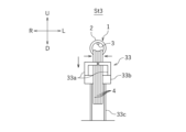
- FIG. 6 is a schematic front view of the third station St3, showing a state in which the core wire 4 is separated.
- the core wire separating device 33 includes a pair of left and right hooks 33a, a hook opening/closing device 33b, and a hook moving device 33c.
- the pair of hooks 33a opens and closes by moving in the left-right direction so as to separate from or approach each other.
- the hook opening/closing device 33b is a drive unit that opens and closes the pair of hooks 33a.
- the hook moving device 33c is a drive unit that vertically moves the pair of hooks 33a.
- the pair of hooks 33a When the pair of hooks 33a are closed, the pair of hooks 33a surround the multicore shielded cable 1 except for the 0 o'clock direction when viewed in the front-rear direction. In this state, when the pair of hooks 33a is moved downward by the hook moving device 33c, the plurality of core wires 4 are hooked on the pair of hooks 33a and bent downward. The drain wire 3 is left unhooked by the pair of hooks 33a. Thereby, the drain line 3 and the plurality of core lines 4 are separated. The position in the circumferential direction where the drain wire 3 is positioned is not limited to the 0 o'clock direction, and the bending direction of the core wire 4 is not limited to downward.
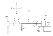
- FIG. 7 is a schematic side view of the fourth station St4.
- the fourth station St4 is provided with a drain wire straightening device 41 for straightening the separated drain wire 3 before the insulation process.
- the drain wire straightening device 41 straightens the separated drain wires 3 by twisting the separated drain wires 3 in the circumferential direction and applying a tensile tension.
- the drain wire straightening device 41 has a rotating clamp 41 a and a clamp moving device 41 b that moves the rotating clamp 41 a in the longitudinal direction of the multicore shielded cable 1 .
- the rotary clamp 41a In the straightening of the drain wire 3, the vicinity of the base of the exposed portion of the drain wire 3 is gripped by the rotary clamp 41a.
- the rotating clamp 41a grips the exposed portion of the drain wire 3 with such a weak gripping force that the gripped portion slips when the rotating clamp 41a is moved forward.
- the drain wire straightening device 41 rotates the rotating clamp 41a and moves it forward while gripping the drain wire 3 with the weak gripping force.
- the drain wire straightening device 41 strengthens the gripping force of the rotating clamp 41a to twist the drain wire 3 firmly.
- the drain wire 3 is strongly twisted and straightened into a straight shape.
- the insulating treatment of the drain wire 3 is facilitated.
- the drain wire straightening device 41 may be configured to apply tensile tension while twisting the drain wire 3 in the circumferential direction, and its operation is not limited to the above.
- the drain wire straightening device 41 may be configured to strongly grip the vicinity of the tip of the drain wire 3 from the beginning and twist the drain wire 3 while applying a pulling tension.
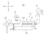
- FIG. 8 is a schematic side view of the fifth station St5.
- the fifth station St5 is provided with an insulating device 51 for insulating the separated drain line 3 .
- the insulation processing device 51 includes a tube reel 52 around which the uncut heat-shrinkable tube 6 is wound, a tube mounting device 53 for inserting the separated drain wire 3 into the heat-shrinkable tube 6, and a drain wire 3 inserted into the heat-shrinkable tube 6. and a heating device 54 for heating the heat-shrinkable tube 6 in the folded state.
- the heat-shrinkable tube 6 is pulled out from the reel by the tube mounting device 53 and cut to a predetermined length by the tube cutter 53a of the tube mounting device 53 .
- the tube mounting device 53 moves the holding portion 53b holding the cut heat-shrinkable tube 6 rearward (toward the fixing clamp 130 side).
- the tube mounting device 53 includes a holding portion moving device 53c that moves the holding portion 53b in the front-rear direction.
- the heating device 54 blows hot air into the holding portion 53b.
- the heat-shrinkable tube 6 is heat-shrunk and the drain wire 3 is insulated.
- the method of insulating the drain wire 3 is not limited to the method of covering the drain wire 3 with the heat-shrinkable tube 6 .
- the insulating treatment of the drain wire 3 may be performed by winding an insulating tape around the drain wire 3, for example.
- the method of covering the drain wire 3 with the heat-shrinkable tube 6 has the advantage of being easily carried out by an automatic machine.
- FIG. 9 is a schematic plan view of the sixth station St6.
- the sixth station St6 includes a bend-back device 61 that bends back the plurality of core wires 4 bent in the separating step, and an alignment device 62 that aligns the drain wire 3 and the plurality of core wires 4. , is provided.
- the bend-returning device 61 is an example of a reverting device for realigning the drain wire 3 and the plurality of core wires 4 separated in the separation step.
- the plurality of core wires 4 that were bent in the separation step are bent back to align the drain wires 3 and the plurality of core wires 4.
- the plurality of core wires 4 (or the drain wires 3) are elastic.
- the return device may be a device that releases the bias of the plurality of core wires 4 (or drain wires 3).
- the unbending device 61 and the aligning device 62 share a part of the configuration and are integrated.
- the multicore shielded cable 1 is stretched in the circumferential direction so that the drain wire 3 and the plurality of core wires 4 are aligned in a predetermined alignment direction, here, in the left-right direction, before the bending-back process and the alignment process.
- a rotation step of rotating is performed.
- the fixing clamp 130 rotates the multicore shielded cable 1 in the circumferential direction to position the drain wire 3 at a predetermined rotational position, here at the 3 o'clock direction in front view. Thereby, as shown in FIG. 9, the drain wire 3 moves to the leftmost among the plurality of core wires.
- the fixing clamp 130 here rotates the multicore shielded cable 1 by 90 degrees.
- the plurality of core wires 4 are positioned to the right of the drain wire 3 .
- the drain wire 3 may be positioned at the right end in the rotating process. Although the details will be described later, by setting the position of the drain line 3 at the left end or the right end, the subsequent steps can be easily performed.
- the bend-back device 61 bends back the drain wire 3 and the plurality of core wires 4 that have been bent by the core wire separation device 33 (here, the core wire 4).
- the unbending device 61 includes a pair of upper and lower rollers 61a (only the lower roller 61a is shown), an opening/closing device (not shown) for the rollers 61a, and a roller moving device 61b.
- the unbending device 61 first drives the opening/closing device to sandwich the exposed root portions of the drain wire 3 and the plurality of core wires 4 (near the remaining sheath 2) between the pair of rollers 61a.
- the roller 61a is configured to rotate in the front-rear direction.
- the roller 61a has a plurality of grooves corresponding to the drain wires 3 and the plurality of core wires 4, respectively. A plurality of grooves are formed along the outer peripheral surface of the roller 61a.
- the bending-back device 61 drives the roller moving device 61b in a state in which the drain wire 3 and the plurality of core wires 4 are sandwiched between the pair of rollers 61a to move the pair of rollers 61a forward.
- the drain wire 3 and the plurality of core wires 4 (particularly the plurality of core wires 4 bent in the separating step) are stretched straight in the front-rear direction along the grooves of the roller 61a.
- the method of bending back the core wire 4 is not limited to the method using the roller as described above.
- the aligning device 62 is configured to align the drain wires 3 and the plurality of core wires 4 in the left-right direction at predetermined intervals. Alignment of the drain wire 3 and the plurality of core wires 4 is performed after the unbending process.
- FIG. 10 is a schematic front view of the sixth station St6, showing a state in which the drain wire 3 and the core wire 4 are aligned.
- the alignment device 62 includes an alignment member 62a for aligning the drain wire 3 and the plurality of core wires 4, and a moving device 62b for bringing the alignment member 62a closer to the drain wire 3 and the plurality of core wires 4. and have.
- the alignment member 62a is a flat member extending in the horizontal direction and the vertical direction, and has a plurality of comb teeth 62a1 arranged in the horizontal direction. A plurality of gaps 62a2 corresponding to the drain wires 3 and the plurality of core wires 4 are provided between the comb teeth 62a1.
- the moving device 62b moves the aligning member 62a in a direction perpendicular to the alignment direction of the core wires, here in the vertical direction, and inserts the drain wires 3 and the plurality of core wires 4 into the plurality of gaps 62a2 of the aligning member 62a.
- the moving device 62b may move the multicore shielded cable 1, or may move both the alignment member 62a and the multicore shielded cable 1.
- the moving device 62b may be configured to move at least one of the aligning member 62a and the multicore shielded cable 1 .
- the plurality of gaps 62a2 are located forward in the direction of movement when the drain wire 3 and the plurality of core wires 4 are inserted (upward in this case, rearward in the direction of movement of the aligning member 62a). It is formed so that it may separate from each other as it goes.
- the plurality of gaps 62a2 are arranged in the left-right direction at predetermined intervals at the front ends of the drain wires 3 and the plurality of core wires 4 in the moving direction (that is, at the ends of the gaps 62a2). As shown in FIG.
- the drain wire 3 and the plurality of core wires 4 are arranged in the horizontal direction at predetermined intervals. This alignment allows the lateral positions of the drain wire 3 and the plurality of core wires 4 to be specified, so that the subsequent process, for example, the transfer process of the multi-core shielded cable 1 to the shuttle 120, can be performed smoothly. .
- the multicore shielded cable 1 is transferred from the transfer device 110 to the shuttle 120.
- the shuttle 120 includes a plurality of individual clamps 120a spaced approximately the same as the aligned drain wires 3 and core wires 4.
- a plurality of individual clamps 120a grip the insulated drain wire 3 and the plurality of core wires 4, respectively.
- each individual clamp 120a is configured to clamp the drain wire 3 or the core wire 4 with elastic force.
- the drain wire 3 and the plurality of core wires 4 are pushed into the plurality of individual clamps 120a by another comb (not shown), for example.
- FIG. 11 the shuttle 120 includes a plurality of individual clamps 120a spaced approximately the same as the aligned drain wires 3 and core wires 4.
- a plurality of individual clamps 120a grip the insulated drain wire 3 and the plurality of core wires 4, respectively.
- each individual clamp 120a is configured to clamp the drain wire 3 or the core wire 4 with elastic force.
- the drain wire 3 and the plurality of core wires 4 are
- the plurality of individual clamps 120a includes an upstream group 120R for gripping the plurality of core wires 3 and 4 exposed at the upstream end of the bent multicore shielded cable 1, and an upstream group 120R. and a downstream group 120L that is arranged downstream of the group 120R in the conveying direction and holds the plurality of core wires 3 and 4 exposed at the downstream end of the bent multicore shielded cable 1. .
- FIG. 11 is a schematic plan view of the seventh station St7.
- the seventh station St7 is provided with a rubber plug mounting device 71 configured to load the tip portion of the core wire 4 and for mounting the rubber plug 7 on the loaded core wire 4.
- the rubber plug mounting device 71 includes a rubber plug supply device 71a and a rubber plug clamp 71b.
- the rubber plug supply device 71a supplies the rubber plug 7 into the rubber plug clamp 71b by, for example, compressed air.
- the rubber plug clamp 71b grips the rubber plug 7 from the outside in the radial direction.
- the shuttle 120 includes a loading device 120b that individually moves a plurality of individual clamps 120a back and forth.
- the loading device 120b individually moves the plurality of individual clamps 120a to individually attach the core wires 4 held by the individual clamps 120a to the rubber stopper mounting device 71 before the coating of the tip of the core wire 4 is stripped off. to load.
- the core wire 4 is inserted into the rubber plug 7 by moving forward together with the individual clamp 120a.
- the shuttle 120 intermittently moves to the left, and the rubber plugs 7 are sequentially attached to the eight ends of the four core wires 4 .
- Such intermittent movement of the shuttle 120 also applies to the stripping process of the core wire, except that the drain wire 3 is also treated.
- the intermittent movement of the shuttle 120 is performed except that the drain wire 3 is also processed and the left end and right end of the multicore shielded cable 1 are processed by different crimping devices 91 and 92. , the same applies to the crimping process.
- FIG. 12 is a schematic plan view of the eighth station St8.
- the eighth station St8 is configured to be loaded with the tip of the drain wire 3 or the core wire 4, and the tip of the loaded drain wire 3 or core wire 4 is stripped.
- a core wire stripping device 81 is provided.
- the loading device 120b of the shuttle 120 individually moves the plurality of individual clamps 120a to individually load the core wire stripping device 81 with the drain wires 3 or the core wires 4 gripped by the individual clamps 120a.
- the core wire stripping device 81 has a pair of stripping blades 81a.
- the drain wire 3 and the plurality of core wires 4 stripped at the ends are cut by a cutter (not shown) of the core wire stripping device 81 so that the positions of the ends are aligned.
- the end positions of the drain wire 3 and the plurality of core wires 4 are specified by the aligning cutting process. As a result, the crimping process can be performed smoothly.
- FIG. 13 is a schematic plan view of the ninth station St9.
- the ninth station St9 is configured to be loaded with the tip of the drain wire 3 or the core wire 4, and the terminal 8 is attached to the tip of the loaded drain wire 3 or core wire 4.
- a right crimping device 91 is provided for crimping.
- a left crimping device 92 is also provided at the ninth station St9.
- the loading device 120b of the shuttle 120 individually moves the plurality of individual clamps 120a to individually press the drain wire 3 or the core wire 4, which is gripped by the individual clamps 120a and whose tip is stripped, to the crimping device 91. Or load 92. Since the configuration of the right crimping device 91 and the configuration of the left crimping device 92 are the same, only the configuration of the right crimping device 91 will be described below.
- the right crimping device 91 includes an applicator 91a, a press (not shown) that presses the applicator 91a, and a terminal reel 91b.
- the applicator 91a includes a crimper (not shown), which is a mold for molding the terminal 8, and an anvil 91a1.
- the crimper and the anvil 91a1 face each other vertically.
- the terminal 8 is supplied from the terminal reel 91b between the crimper and the anvil 91a1, and when the press is driven with the tip of the core wire of the multi-core shielded cable 1 inserted between the crimper and the anvil 91a1, the crimper and the anvil 91a1 are driven.
- the mounting of the rubber plug 7, the stripping of the core wire, and the crimping of the terminal 8 are performed for each core wire in terms of quality control. Therefore, in this embodiment, the drain wire 3 or the core wire 4 is loaded one by one into the rubber plug mounting device 71, the core wire stripping device 81, the right crimping device 91, or the left crimping device 92 by the loading device 120b. In this embodiment, since the right and left positions of the core wire are specified by the alignment process, the mounting of the rubber plug 7, the stripping of the core wire, and the crimping of the terminal 8 can be reliably carried out.
- the position of the drain wire 3 is also specified in the post-process (that is, it is known that the core wire at the left end is the drain wire 3). Therefore, it can be easily determined whether it is the turn to process the drain wire 3 or the turn to process the core wire 4 in the subsequent process. For example, when using a terminal 8 for the drain wire 3 different from that for the core wire 4 in the crimping process, it is necessary to specify the position of the drain wire 3 .
- the attachment of the rubber plug 7, the stripping of the core wires 3 and 4, and the crimping of the terminal 8 must be performed for all the core wires 3 and 4 (all the core wires 4 when the rubber plug 7 is attached). good too. These steps may not be performed on the drain lines 3 and some core lines 4 may not be performed. Exposed portions of the drain wire 3 or core wire 4 not subjected to these steps may be cut off prior to these steps.
- the conveying device for the multicore shielded cable 1 in the processing device 200 may be configured as follows.
- the configuration of the conveying device is not limited to the following.
- FIG. 14 is a rear view of the conveying device for the multicore shielded cable 1.
- the conveying device for the multicore shielded cable 1 includes a cutting device 21, a sheath semi-stripping device 22, a drain wire detecting device 31, a sheath stripping device 32 (drain A rotating device that rotates the multi-core shielded cable 1 based on the circumferential position of the drain wire 3 detected by the wire detection device 31 and positions the drain wire 3 at a predetermined rotational position (here, the 0 o'clock position).
- the second conveying device 119 includes a shuttle 120 having a plurality of individual clamps 120a for respectively holding a plurality of core wires 3 and 4 of the multicore shielded cable 1, and a shuttle conveying device 121 for moving the shuttle 120. .
- the second transport device 119 comprises a plurality of shuttles 120 .
- the first conveying device 110 is provided so as to face the plurality of processing stations St2 to St6, respectively, and is configured to hold a plurality of fixing clamps 130 that hold the multicore shielded cable 1 and each hold the multicore shielded cable 1. and a plurality of transfer clamps 111 that reciprocate between two adjacent fixed clamps 130 out of the plurality of fixed clamps 130 .
- the fixed clamp 130 is an example of a fixed gripping device that grips the multicore shielded cable 1 .
- the plurality of transport clamps 111 of the first transport device 110 are arranged at the same pitch in the transport direction of the multicore shielded cable 1 and reciprocate in the transport direction.
- the clamp moving device 112 of the first conveying device 110 includes a slide rail 112a extending in the conveying direction and engaged with the plurality of conveying clamps 111, a driving unit 112b for moving the plurality of conveying clamps 111 along the slide rail 112a, It has A plurality of fixed clamps 130 as fixed gripping devices are arranged so as to be aligned in the front-rear direction with the respective transfer clamps 111 at the stop position.
- the pitch of the plurality of fixed clamps 130 is the same as the pitch of the plurality of transfer clamps 111 and is constant.
- the two most upstream transport clamps 111 in the transport direction grip the U-shaped multicore shielded cable 1 at two points and move it to a position directly facing the second station St2.
- Two fixing clamps 130 arranged behind the second station St2 grip the transported multi-core shielded cable 1 at two points. After that, the transport clamp 111 returns to the rear of the first station St1 and grips the next multicore shielded cable 1 .
- Other transport clamps 111 and other fixed clamps 130 operate similarly. As a result, a plurality of multicore shielded cables 1 are sequentially transported downstream in the transport direction.
- the shuttle transport device 121 of the second transport device 119 includes a take-up position P0 at which the multicore shielded cable 1 is taken in, a first facing position P1 facing the core wire stripping device 81, and crimping devices (right crimping device 91 and left crimping device 92). ), and in the case of the processing apparatus 200 provided with the rubber plug mounting device 71, the third facing position P3 facing the rubber plug mounting device 71 and the position after the terminal 8 is crimped.
- the shuttle 120 is moved between a release position P4 where the multicore shielded cable 1 is released.
- the shuttle transport device 121 circulates a plurality of shuttles 120 .
- the shuttle transport device 121 may reciprocate or circulate one shuttle 120 .
- the first facing position P1 is the upstream first position where the downstream end of the multicore shielded cable 1 faces the core wire stripping device 81 . and a first downstream facing position where the upstream end of the multicore shielded cable 1 faces the core wire stripping device 81 .
- the second facing position P2 is the upstream second facing position where the downstream end of the multicore shielded cable 1 faces the right crimping device 91 and the left side crimping device 92 where the upstream end of the multicore shielded cable 1 faces. and a second downstream facing position facing the .
- the devices provided in the respective processing stations St7 to St9 operate downstream while the devices provided in the processing stations adjacent to the upstream side are processing the upstream end of the multicore shielded cable 1. configured to machine side edges.
- the right crimping device 91 crimps the terminal 8 to the downstream end of the multicore shielded cable 1 while the core wire stripping device 81 is stripping the upstream end of the multicore shielded cable 1 . Therefore, in the present embodiment, for example, the first downstream facing position and the second upstream facing position are the same position. In this way, the take-up position P0, the third facing position P3, the first facing position P1, the second facing position P2, and the release position P4 may partially overlap.
- the shuttle transport device 121 includes a circulation member 121a to which a plurality of shuttles 120 are fixed and which travels in a loop, and a drive section 121b which circulates the circulation member 121a.
- the circulation member 121a is, for example, an endless belt or chain.
- the circulation member 121a is configured to draw a loop when viewed in the front-rear direction.
- the circulatory movement of the shuttle 120 includes lateral movement between the pick-up position P0, the third facing position P3, the first facing position P1, and the second facing position P2, and the pick-up position P0, the third facing position P3. , a first facing position P1, and a vertical movement to a position lower than the second facing position P2.
- the release position P4 is set in the upper stage of the loop along with the take-up position P0, the third facing position P3, the first facing position P1, and the second facing position P2. It may be set between the lower stage.
- the circulation member 121a may, for example, be arranged along a horizontal plane and configured to draw a loop in plan view.
- the plurality of individual clamps 120a of the shuttle 120 grip the plurality of core wires 3, 4 when the shuttle 120 moves from a position below the take-up position P0 to the take-up position P0.
- the individual clamp 120a has a U-shape with an open top, and holds the drain wire 3 or the core wire 4 inside the U-shape.
- the individual clamp 120a has elasticity so that the core wires 3 and 4 can be inserted inside the U shape and held after insertion.
- the core wires 3 and 4 are pushed into the individual clamps 120a by the upward movement of the shuttle 120 toward the take-up position P0 and the action of the pressing member of the aligning device 62 covering the core wires 3 and 4 from above.
- the processing apparatus 200 includes the cutting device 21, the sheath semi-stripping device 22, the drain wire detecting device 31, the sheath stripping device 32 (including the rotary clamp 32a), the core wire separating device 33, the drain A first conveying device 110 for conveying the multicore shielded cable 1 to the wire straightening device 41, the insulation processing device 51, the bendback device 61, and the alignment device 62, the rubber plug mounting device 71, the core wire stripping device 81, and the crimping device 91. , 92 and a second conveying device 119 for conveying the multicore shielded cable 1 to 92 .
- the second conveying device 119 includes a shuttle 120 having a plurality of individual clamps 120a for respectively holding a plurality of core wires 3 and 4, and a shuttle conveying device 121 for moving the shuttle 120.
- the shuttle conveying device 121 has a take-up position P0 at which the multicore shielded cable 1 is taken in, a third facing position P3 facing the rubber plug mounting device 71, a first facing position P1 facing the core wire stripping device 81, and a crimping device 91. , 92 and a release position P4 where the multicore shielded cable 1 is released after the terminal 8 is crimped.
- the multicore shielded cable 1 can be transported without re-grasping the core wires 3 and 4 during the attachment of the rubber plug 7, the stripping of the core wires 3 and 4, and the crimping of the terminal 8. . Therefore, the positions of the core wires 3 and 4 are stabilized without changing the gripping position. As a result, the mounting of the rubber plug 7, the stripping of the core wires 3 and 4, and the crimping of the terminal 8 can be performed with high quality.
- the shuttle transport device 121 circulates a plurality of shuttles 120 .
- the shuttle 120 can be returned from the release position P4 to the take-up position P0, and the multicore shielded cable 1 is continuously transported.
- productivity can be improved.
- the circulatory movement of the shuttle 120 includes lateral movement between the pick-up position P0, the third facing position P3, the first facing position P1, and the second facing position P2, and the pick-up position P0, the third facing position P3. , a first facing position P1, and a vertical movement to a position lower than the second facing position P2.
- the multiple individual clamps 120a of the shuttle 120 grip the multiple core wires 3, 4 when the shuttle 120 moves from a position below the take-up position P0 to the take-up position P0.
- the core wires 3 and 4 can be gripped by utilizing the vertical movement of the shuttle 120 during its circulating movement, so the process time can be shortened.
- the first transfer device 110 is provided to face the plurality of processing stations St2 to St6, respectively, and includes a plurality of fixing clamps 130 for holding the multicore shielded cable 1, and the multicore shielded cable 1. a plurality of transfer clamps 111 that are configured to grip and reciprocate between two adjacent fixed clamps 130 of the plurality of fixed clamps 130 . Depending on the number of fixed clamps 130, only one transport clamp 111 may be used. According to the processing apparatus 200, in a process that does not require a high degree of positioning for transporting the multicore shielded cable 1 (here, the process of cutting the sheath 2 to the alignment of the core wires 3 and 4), the transport clamp 111 reciprocates. While moving, the multi-core shielded cable 1 is re-gripped. This simplifies the configuration of the transfer device (first transfer device 110) for the multicore shielded cable 1 in this process.
- the multicore shielded cable 1 in a process that does not require a high degree of positioning regarding the transport of the multicore shielded cable 1, the multicore shielded cable 1 is re-clamped to simplify the first transport device 110, and the positional accuracy of the core wires 3 and 4 is improved. (here, from mounting the rubber plug 7 to crimping the terminal 8), the multi-core shielded cable 1 is not re-clamped, and the shuttle 120 is moved while gripping the core wires 3 and 4. As a result, the processing apparatus 200 as a whole is simplified, and the processing quality of the multicore shielded cable 1 is enhanced.
- the plurality of processing stations St2 to St6 are arranged side by side in the conveying direction of the multicore shielded cable 1 by the conveying clamp 111.
- FIG. The processing device 200 is arranged upstream in the transport direction from the plurality of processing stations St2 to St6, and bends the multicore shielded cable 1 into a substantially U shape so that both ends are aligned in the transport direction. (although it may be a dedicated bending device).
- the plurality of fixing clamps 130 are each configured to grip one end of the multicore shielded cable 1 bent by the bending device 110A.
- the devices provided in each of the processing stations St2 to St6 operate on the downstream side while the devices provided in the processing stations adjacent to the upstream side are processing the upstream end portion of the bent multicore shielded cable 1. Process the ends. According to such a configuration, both ends of the multicore shielded cable 1 can be processed simultaneously, so productivity can be improved.
- the plurality of individual clamps 120a of the shuttle 120 includes an upstream group 120R for gripping the plurality of core wires 3, 4 exposed at the upstream end of the bent multicore shielded cable 1, and an upstream group 120R.
- a downstream group 120L arranged downstream in the conveying direction from the side group 120R and holding a plurality of core wires 3 and 4 exposed at the downstream end of the bent multicore shielded cable 1; there is According to such a configuration, both ends of the U-bent multicore shielded cable 1 can be gripped even in the process of conveying the multicore shielded cable 1 by the shuttle 120 .
- the devices provided at the respective processing stations St7 to St9 are arranged upstream of the multicore shielded cable 1 and the device provided at the processing station adjacent to the upstream side. Process the downstream end while processing the side end.
- FIG. 15 is a rear view of a conveying device for a multicore shielded cable 1 according to another embodiment.
- the transfer device for the multicore shielded cable 1 includes a transfer device 140 that receives the multicore shielded cable 1 from the first transfer device 110 and transfers the multicore shielded cable 1 to the second transfer device 119 . may By providing the transfer device 140, direct transfer of the multicore shielded cable 1 from the first transfer device 110 to the second transfer device 119 is eliminated.
- the transfer device 140 is arranged between the fifth station St5 and the sixth station St6.
- the first conveying device 110 conveys the multicore shielded cable 1 from the second station St2 to the transfer device 140 via the fifth station St5.
- the second conveying device 119 receives the multicore shielded cable 1 from the transfer device 140 at the receiving position P0, and conveys it to the tenth station St10.
- the plurality of individual clamps 120a of the second transport device 119 are arranged in multiple positions so that the distance between both ends of the multicore shielded cable 1 is narrower than that of the plurality of fixed clamps 130 of the first transport device 110.
- the core shield cable 1 is gripped.
- the length of the processing apparatus 200 in the conveying direction can be shortened.
- the width of the shuttle 120 in the transport direction can be narrowed.
- the stations St2 to St5 where the first conveying device 110 conveys the multicore shielded cable 1 the distance between both ends of the multicore shielded cable 1 is wide, so there is a degree of freedom and margin in the arrangement of the devices.
- the delivery device 140 shortens the distance between both ends of the shielded multicore cable 1.
- the delivery device 140 is provided with a function of narrowing the space between both ends of the multicore shielded cable 1, so that the device for narrowing the space between both ends of the multicore shielded cable 1 and the delivery device 140 are shared. .
- the transfer device 140 includes a pair of clamps 141 that hold both ends of the multicore shielded cable 1, a drive device 142 that moves the pair of clamps 141 closer to or away from each other, and the clamps 141 and the drive device 142. It includes a moving body 143 to be supported, an elevating device 144 for moving the moving body 143 in the vertical direction, and a slide device 145 for moving the moving body 143 in the transport direction.
- the delivery device 140 moves the moving body 143 above the most downstream transport clamp 111 (moved downstream) by the slide device 145. .
- the transfer device 140 lowers the moving body 143 by the lifting device 144 to a position where the vertical position of the clamp 141 is the same as that of the multicore shielded cable 1 .
- the pair of clamps 141 grip both ends of the multicore shielded cable 1 .
- the distance between the pair of clamps 141 corresponds to the distance between both ends of the multicore shielded cable 1 when it is held by the first conveying device 110 .
- the transfer device 140 raises the moving body 143 when the pair of clamps 141 grip the multicore shielded cable 1 . Further, the transfer device 140 moves the moving body 143 downstream in the transport direction to above the shuttle 120 at the pick-up position P0. During this time, the driving device 142 brings the pair of clamps 141 closer together so that the distance between the pair of clamps 141 corresponds to the distance between both ends of the multicore shielded cable 1 when it is held by the second conveying device 119 . The driving device 142 moves the pair of clamps 141 toward or away from each other so that the distance between the pair of clamps 141 corresponds to the distance between both ends of the multicore shielded cable 1 held by the first conveying device 110.
- the delivery device 140 then descends and delivers the multicore shielded cable 1 to the shuttle 120 at the take-up position P0.
- the driving device 142 rotates the pair of clamps 141 around a rotation axis arranged at a position different from the axis of the multicore shielded cable 1 that is gripped, so that the distance between both ends of the multicore shielded cable 1 is reduced. change the distance.
- the driving device 142 rotates the upstream clamp 141R downstream by 90 degrees around the rotation axis Ar. Further, the driving device 142 rotates the downstream side clamp 141L about the rotation axis Al by 90 degrees to the upstream side. As a result, the distance between both ends of the multicore shielded cable 1 is reduced.
- both ends of the multicore shielded cable 1 are rotated not by the fixing clamp 130 but by the driving device 142, so that the multiple core wires 3 and 4 are arranged in the conveying direction.
- the core wire 4 can be bent back by the bend-back device 61 and the alignment device 62 to align the drain wire 3 and the plurality of core wires 4 .
- the configuration of the delivery device 140 is not limited to the one described above.
- the configuration in which the transfer device 140 changes the distance between both ends of the multicore shielded cable 1 is not limited to the configuration in which the clamp 141 is rotated.
- the transfer device 140 may be configured to change the distance between both ends of the multicore shielded cable 1 by, for example, sliding one or both of the pair of clamps 141 in the conveying direction. The delivery device 140 does not need to move the multicore shielded cable 1 up and down.
- the plurality of individual clamps 120a of the second conveying device 119 are arranged so that the distance between both ends of the multicore shielded cable 1 is narrower than that of the plurality of fixed clamps 130 of the first conveying device 110.
- the multicore shielded cable 1 is gripped in 1, both ends of the multicore shielded cable 1 may be gripped at the same interval as the fixing clamp 130 grips.
- the position of the drain wire 3 is detected after the sheath 2 is semi-stripped, and then the sheath 2 is completely stripped.
- the position of the drain wire 3 may be detected after the sheath 2 is completely stripped.
- the strip length of the sheath 2 is short and the twisting of the core wire does not matter, the untwisting of the core wire in the strip of the sheath 2 may not be performed.
- the straightening process of the drain wire 3 may not be performed.
- the multicore shielded cable 1 including the drain wire 3 and a plurality of core wires 4 is processed.
- the cable to be processed may be a multicore cable that does not include drain wires.
- the multicore cable processing device may be a device for processing a multicore cable having a sheath and a plurality of core wires inserted through the sheath.
- the multicore cable processing device includes a cutting device that forms a cut in the sheath along the circumferential direction, and at least one of the sheath on the tip side and the sheath on the root side of the multicore cable from the cut. a pulling device for moving in the longitudinal direction of the wire to expose the plurality of core wires.
- the multi-core cable processing device further comprises a detection device for detecting the position of a specific core wire among the plurality of core wires in the circumferential direction of the multi-core cable, and a multi-core cable based on the detected position of the specific core wire in the circumferential direction. and a rotating device that rotates the cable and moves the specific core wire to a predetermined circumferential position.
- the specific core wire may be the drain wire, but may be another core wire.
- the multicore cable is rotated based on the circumferential position of the specific core wire detected by the detection device, and the position of the specific core wire is changed from the predetermined circumferential position. can do. Along with this, the positions of the plurality of core wires are determined. This makes it possible to specify the position of each core wire of the multicore cable.
- Multi-core shielded cable (multi-core cable) 2 Sheath 3 Drain wire (core wire) 4 core wire (core wire) 6 Heat-shrinkable tube 7 Rubber stopper (waterproof rubber stopper) 8 terminal 21 cutting device 22 sheath semi-strip device (extraction device) 31 drain wire detection device (detection device) 32 sheath strip device (withdrawal device) 32a rotating clamp (rotating device) 33 core wire separation device (separation device) 41 Drain wire straightening device (straightening device) 51 insulation processing device 53 tube mounting device (insertion device) 54 Heating device 61 Unbending device 62 Aligning device 62a Aligning member 62b Moving device 71 Rubber stopper mounting device 81 Core wire stripping device (stripping device) 91 right crimping device (crimping device) 92 left side crimping device (crimping device) 110 transport device (first transport device) 110A bending device 111 transport clamp (grasping device, moving gripping device) 112 clamp moving device (grasping device moving
Abstract
A processing device 200 for a multicore cable 1 is a device for processing the multicore cable 1, which includes a sheath 2 and a plurality of core wires 3, 4 that are inserted through the sheath 2, the processing device 200 comprising: a cutting device 21 for forming a circumferential-direction slit in the sheath 2; a withdrawing device 22 for exposing the plurality of core wires 3, 4 by moving, in a longitudinal direction of the multicore cable 1, at least one of the sheath 2 closer to a tip end side of the multicore cable 1 than the slit, and the sheath 2 closer to a base side of the multicore cable 1 than the slit; a detecting device 31 for detecting a position, in relation to the circumferential direction of the multicore cable 1, of a specific core wire 3 among the plurality of core wires 3, 4; and a rotating device 32a for rotating the multicore cable 1 on the basis of the detected position, in the circumferential direction, of the specific core wire 3, to move the specific core wire 3 to a predetermined circumferential-direction position.
Description
本発明は、多芯ケーブルの加工装置に関する。
The present invention relates to a processing device for multicore cables.
ドレイン線を有する多芯シールドケーブルのドレイン線を絶縁処理する方法が従来から提案されている。例えば特許文献1には、シースを除去して被覆電線(コア線)とドレイン線とを露出させた後に、ドレイン線を90度曲げてコア線から分離し、熱収縮チューブにドレイン線を挿入するドレイン線の絶縁処理方法が開示されている。特許文献1に開示された方法では、その後、熱収縮チューブが加熱収縮されることにより、ドレイン線が絶縁処理される。
Conventionally, there have been proposed methods for insulating the drain wires of multi-core shielded cables that have drain wires. For example, in Patent Document 1, after the sheath is removed to expose the covered wire (core wire) and the drain wire, the drain wire is bent 90 degrees to be separated from the core wire, and the drain wire is inserted into a heat-shrinkable tube. A method of insulating a drain line is disclosed. In the method disclosed in Patent Literature 1, the drain wire is then insulated by heat-shrinking the heat-shrinkable tube.
特許文献1に開示されている方法では、ドレイン線を曲げてコア線から分離し、熱収縮チューブにドレイン線を挿入する作業は、手作業により行われている。このように、多芯ケーブルの各芯線の処理は自動化されていない場合があるが、その理由の1つとして、多芯ケーブルの各芯線の位置が特定されていないことが挙げられる。ここでは、多芯ケーブルの複数の芯線に対して処理を行いやすくするために、多芯ケーブルの複数の芯線の位置を特定できる多芯ケーブルの加工装置を提案する。
In the method disclosed in Patent Document 1, the operation of bending the drain wire to separate it from the core wire and inserting the drain wire into the heat-shrinkable tube is performed manually. In this way, processing of each core wire of a multicore cable may not be automated, and one of the reasons is that the position of each core wire of the multicore cable is not specified. Here, a multi-core cable processing apparatus capable of specifying the positions of the plurality of core wires of the multi-core cable is proposed in order to facilitate the processing of the multiple core wires of the multi-core cable.
本発明に係る多芯ケーブルの加工装置は、シースと前記シースに挿通された複数の芯線とを有する多芯ケーブルを加工する装置であって、周方向に沿った切れ目を前記シースに形成する切込装置と、前記切れ目よりも前記多芯ケーブルの先端側のシースと根元側のシースとのうちの少なくとも一方を前記多芯ケーブルの長手方向に移動させて、前記複数の芯線を露出させる引き抜き装置と、前記複数の芯線のうち特定の芯線の前記多芯ケーブルの周方向に関する位置を検出する検出装置と、前記検出された前記特定の芯線の周方向の位置に基づいて前記多芯ケーブルを回転させ、前記特定の芯線を予め定められた周方向の位置に移動させる回転装置と、を備えている。
A multi-core cable processing apparatus according to the present invention is an apparatus for processing a multi-core cable having a sheath and a plurality of core wires inserted through the sheath, wherein a slit is formed in the sheath along the circumferential direction. and a pulling device for exposing the plurality of core wires by moving at least one of the sheath on the tip side of the multicore cable and the sheath on the base side of the cut in the longitudinal direction of the multicore cable. a detecting device for detecting the position of a specific core wire among the plurality of core wires in the circumferential direction of the multicore cable; and rotating the multicore cable based on the detected position of the specific core wire in the circumferential direction. and a rotating device for moving the specific core wire to a predetermined position in the circumferential direction.
上記多芯ケーブルの加工装置によれば、検出装置によって検出された特定の芯線の周方向の位置に基づいて多芯ケーブルを回転させ、特定の芯線の位置を予め定められた周方向の位置とすることができる。これにより、多芯ケーブルの複数の芯線の位置を特定することができる。
According to the multicore cable processing apparatus, the multicore cable is rotated based on the circumferential position of the specific core wire detected by the detection device, and the position of the specific core wire is changed from the predetermined circumferential position. can do. This makes it possible to identify the positions of the core wires of the multicore cable.
本発明に係る多芯ケーブルの加工装置の好ましい一態様によれば、前記複数の芯線は、ドレイン線と複数のコア線からなっており、前記特定の芯線は、前記ドレイン線である。多芯ケーブルの加工装置は、前記検出されたドレイン線の周方向の位置に基づき、前記ドレイン線および前記複数のコア線のうちの少なくとも一方を付勢することによって、前記ドレイン線と前記複数のコア線とを分離する分離装置と、前記分離されたドレイン線を絶縁処理する絶縁処理装置と、前記切込装置、前記引き抜き装置、前記検出装置、前記回転装置、前記分離装置、および前記絶縁処理装置に前記多芯ケーブルを搬送する第1搬送装置と、をさらに備えている。
According to a preferred aspect of the multicore cable processing apparatus of the present invention, the plurality of core wires are composed of a drain wire and a plurality of core wires, and the specific core wire is the drain wire. The multicore cable processing device urges at least one of the drain wire and the plurality of core wires based on the detected circumferential position of the drain wire, thereby separating the drain wire and the plurality of core wires. A separation device for separating the core wire, an insulation treatment device for insulating the separated drain wire, the cutting device, the extraction device, the detection device, the rotation device, the separation device, and the insulation treatment and a first conveying device for conveying the multicore cable to the apparatus.
上記多芯ケーブルの加工装置によれば、多芯ケーブルがドレイン線を備えた多芯シールドケーブルである場合に、ドレイン線の絶縁処理までの多芯シールドケーブルの加工を自動で行うことができる。
According to the above multicore cable processing apparatus, when the multicore cable is a multicore shielded cable having a drain wire, the processing of the multicore shielded cable up to the insulation treatment of the drain wire can be automatically performed.
本発明の好ましい一態様によれば、多芯ケーブルの加工装置は、前記絶縁処理の前に、前記分離されたドレイン線を周方向に撚りながら引っ張りテンションを加えることにより矯正する矯正装置をさらに備えている。
According to a preferred aspect of the present invention, the apparatus for processing a multicore cable further includes a straightening device for straightening the separated drain wires by twisting them in the circumferential direction and applying a tensile tension before the insulation treatment. ing.
上記多芯ケーブルの加工装置によれば、ドレイン線が矯正されることにより、ドレイン線の絶縁処理を容易に行うことができる。
According to the multicore cable processing apparatus, the drain wire can be easily insulated by correcting the drain wire.
本発明に係る多芯ケーブルの加工装置の好ましい一態様によれば、前記絶縁処理装置は、前記分離されたドレイン線を熱収縮チューブに挿入する挿入装置と、前記ドレイン線が挿入された状態の前記熱収縮チューブを加熱する加熱装置と、を備えている。
According to a preferred aspect of the multicore cable processing apparatus according to the present invention, the insulation processing apparatus includes an insertion apparatus for inserting the separated drain wire into a heat-shrinkable tube, and a and a heating device for heating the heat-shrinkable tube.
上記多芯ケーブルの加工装置によれば、熱収縮チューブにドレイン線を挿入し、熱収縮チューブを熱収縮させることにより絶縁処理が行われる。そのため、他の方法、例えば、ドレイン線に絶縁テープを巻き付ける方法に比べて、自動機による絶縁処理を行いやすい。
According to the multi-core cable processing apparatus, insulation processing is performed by inserting the drain wire into the heat-shrinkable tube and heat-shrinking the heat-shrinkable tube. Therefore, compared with other methods, for example, the method of winding an insulating tape around the drain wire, it is easier to perform the insulating treatment by an automatic machine.
本発明に係る多芯ケーブルの加工装置の好ましい一態様によれば、前記引き抜き装置は、前記先端側のシースが前記根元側のシースに対して周方向に回転するように前記先端側のシースおよび前記根元側のシースのうちの少なくとも一方を回転させながら、前記先端側のシースを引き抜き、前記複数の芯線の撚りをほどくように構成されている。
According to a preferred aspect of the apparatus for processing a multicore cable according to the present invention, the pulling device rotates the sheath on the distal end side and While rotating at least one of the sheaths on the root side, the sheath on the tip side is pulled out to untwist the plurality of core wires.
上記多芯ケーブルの加工装置によれば、複数の芯線の撚りをほどくことにより、検出装置による特定の芯線の位置の検出を容易に行うことができる。
According to the multi-core cable processing device, by untwisting a plurality of core wires, the detection device can easily detect the position of a specific core wire.
本発明に係る多芯ケーブルの加工装置の好ましい一態様によれば、前記引き抜き装置は、前記複数の芯線の一部が露出し、かつ、前記複数の芯線の他の一部に前記先端側のシースが残るように前記先端側のシースを引き抜くセミストリップを、前記検出装置による前記特定の芯線の検出よりも前に行うように構成されている。また、前記引き抜き装置は、前記先端側のシースを前記複数の芯線から離脱させる全ストリップを、前記検出装置による前記特定の芯線の検出よりも後に行うように構成されている。
According to a preferred aspect of the multi-core cable processing apparatus according to the present invention, the pull-out device exposes a part of the plurality of core wires, and attaches the other part of the plurality of core wires to the distal end side. The semi-stripping of pulling out the sheath on the distal end side so that the sheath remains is performed prior to the detection of the specific core wire by the detection device. Further, the extracting device is configured to perform all stripping, in which the sheath on the distal end side is detached from the plurality of core wires, after detection of the specific core wire by the detection device.
上記多芯ケーブルの加工装置によれば、検出装置による特定の芯線の位置の検出時に、芯線がばらけて検出がしにくくなるのを防ぐことができる。
According to the above multi-core cable processing device, when detecting the position of a specific core wire by the detection device, it is possible to prevent the core wires from becoming loose and making detection difficult.
本発明の好ましい一態様によれば、多芯ケーブルの加工装置は、前記複数の芯線を所定の間隔で並ばせる整列装置をさらに備えている。前記整列装置は、整列部材と、移動装置と、を備えている。前記整列部材は、複数の櫛歯を有し、前記複数の芯線に対応した複数の隙間が前記櫛歯同士の間に設けられている。前記移動装置は、前記整列部材および前記多芯ケーブルのうちの少なくとも一方を移動させ、前記複数の芯線を前記整列部材の前記複数の隙間にそれぞれ挿入する。前記複数の隙間は、前記複数の芯線が挿入される際の移動方向前方に向かうほど互いに離れるように形成され、前記移動方向の前端において前記所定の間隔で並んでいる。
According to a preferred aspect of the present invention, the multi-core cable processing device further includes an alignment device for aligning the plurality of core wires at predetermined intervals. The alignment device comprises an alignment member and a moving device. The alignment member has a plurality of comb teeth, and a plurality of gaps corresponding to the plurality of core wires are provided between the comb teeth. The moving device moves at least one of the alignment member and the multicore cable, and inserts the plurality of core wires into the plurality of gaps of the alignment member. The plurality of gaps are formed so as to separate from each other toward the front in the moving direction when the plurality of core wires are inserted, and are arranged at the predetermined intervals at the front end in the moving direction.
上記多芯ケーブルの加工装置によれば、複数の芯線が所定の間隔で整列され、それぞれの位置が特定される。その結果、後工程での複数の芯線の処理が容易となる。
According to the multi-core cable processing device, a plurality of core wires are aligned at predetermined intervals, and their respective positions are specified. As a result, it becomes easier to process the plurality of core wires in the post-process.
本発明の好ましい一態様によれば、多芯ケーブルの加工装置は、それぞれ1本の前記芯線を把持可能な複数の把持部材と、前記芯線の先端部が装填されるように構成され、装填された前記芯線の先端部の被覆を剥くストリップ装置と、前記複数の把持部材を個別に移動させて、前記把持部材に把持された前記芯線を個別に前記ストリップ装置に装填する装填装置と、をさらに備えている。
According to a preferred aspect of the present invention, the apparatus for processing a multicore cable is configured and loaded with a plurality of gripping members each capable of gripping one of the core wires and a tip portion of the core wire. and a loading device for individually moving the plurality of gripping members and individually loading the core wires gripped by the gripping members into the stripping device. I have.
多芯ケーブルの芯線のストリップは、品質管理上、芯線の1本ずつに対して行うことが好ましい。上記多芯ケーブルの加工装置によれば、複数の芯線は、装填装置により1本ずつストリップ装置に装填される。そのため、芯線のストリップの品質を確保することができる。
For quality control, it is preferable to strip the core wires of multi-core cables one by one. According to the multicore cable processing apparatus, the plurality of core wires are loaded into the stripping device one by one by the loading device. Therefore, the quality of the core wire strip can be ensured.
本発明の好ましい一態様によれば、多芯ケーブルの加工装置は、前記芯線の先端部が装填されるように構成され、装填された前記芯線の先端部に端子を圧着する圧着装置をさらに備えている。前記装填装置は、前記複数の把持部材を個別に移動させて、前記把持部材に把持されるとともに先端部の被覆が剥かれた前記芯線を、個別に前記圧着装置に装填するように構成されている。
According to a preferred aspect of the present invention, the apparatus for processing a multicore cable further includes a crimping device configured to be loaded with the tip of the core wire and crimping a terminal to the tip of the loaded core wire. ing. The loading device is configured to individually move the plurality of gripping members, and individually load the core wires, which are gripped by the gripping members and whose distal ends have been stripped, into the crimping device. there is
芯線への端子の圧着も、品質管理上、芯線の1本ずつに対して行うことが好ましい。よって、上記多芯ケーブルの加工装置によれば、芯線への端子圧着の品質を確保することができる。
For quality control, it is preferable to crimp the terminal to the core wire one by one. Therefore, according to the multicore cable processing apparatus, it is possible to ensure the quality of terminal crimping to core wires.
本発明に係る多芯ケーブルの加工装置の好ましい一態様によれば、前記複数の芯線は、複数のコア線を含んでいる。多芯ケーブルの加工装置は、前記コア線の先端部が装填されるように構成され、装填された前記コア線に防水ゴム栓を装着するゴム栓装着装置をさらに備えている。前記装填装置は、前記コア線の先端部の被覆が剥かれる前に、前記複数の把持部材を個別に移動させて、前記把持部材に把持された前記コア線を個別に前記ゴム栓装着装置に装填するように構成されている。
According to a preferred aspect of the multicore cable processing apparatus of the present invention, the plurality of core wires includes a plurality of core wires. The multi-core cable processing apparatus further includes a rubber plug mounting device configured to load the tip of the core wire and mounting a waterproof rubber plug to the loaded core wire. The loading device individually moves the plurality of gripping members to individually move the core wires gripped by the gripping members to the rubber plug mounting device before the coating of the tip portion of the core wire is stripped. configured to load.
コア線への防水ゴム栓の装着も、品質管理上、コア線の1本ずつに対して行うことが好ましい。よって、上記多芯ケーブルの加工装置によれば、コア線への防水ゴムの装着の品質を確保することができる。
For quality control, it is preferable to attach waterproof rubber plugs to core wires one by one. Therefore, according to the multicore cable processing apparatus, it is possible to ensure the quality of attaching the waterproof rubber to the core wires.
本発明の好ましい一態様によれば、多芯ケーブルの加工装置は、前記切込装置、前記引き抜き装置、前記検出装置、および前記回転装置のうちの少なくとも1つが設けられた加工ステーションと、前記加工ステーションと所定方向に並んで配置され、前記切込装置、前記引き抜き装置、前記検出装置、および前記回転装置のうちの他の少なくとも1つが設けられた他の加工ステーションと、前記切込装置、前記引き抜き装置、前記検出装置、および前記回転装置に前記多芯ケーブルを搬送する第1搬送装置と、をさらに備えている。前記第1搬送装置は、一端と他端とが前記所定方向に並ぶように曲げられた前記多芯ケーブルを把持する把持装置と、前記把持装置を前記所定方向に移動させる把持装置移動装置と、を備えている。前記他の加工ステーションに設けられた装置は、前記加工ステーションに設けられた装置が前記多芯ケーブルの前記一端を加工しているときに前記他端を加工する。
According to a preferred aspect of the present invention, a multicore cable processing apparatus includes a processing station provided with at least one of the cutting device, the pulling device, the detecting device, and the rotating device; another processing station arranged side by side with the station in a predetermined direction and provided with at least one other of the cutting device, the pulling device, the detecting device, and the rotating device; It further comprises a first conveying device that conveys the multicore cable to the pulling device, the detecting device, and the rotating device. The first conveying device includes a gripping device that grips the multicore cable bent so that one end and the other end are aligned in the predetermined direction, a gripping device moving device that moves the gripping device in the predetermined direction, It has The device provided at the other processing station processes the other end of the multicore cable while the device provided at the processing station is processing the one end.
上記多芯ケーブルの加工装置によれば、多芯ケーブルの一端と他端とを同時に加工できる。そのため、多芯ケーブルの加工のサイクルタイムを短縮できる。
According to the multicore cable processing device, one end and the other end of the multicore cable can be processed at the same time. Therefore, the cycle time for processing the multicore cable can be shortened.
本発明の好ましい一態様によれば、多芯ケーブルの加工装置は、前記切込装置、前記引き抜き装置、前記検出装置、および前記回転装置に前記多芯ケーブルを搬送する第1搬送装置と、前記芯線の先端部が装填されるように構成され、装填された前記芯線の先端部の被覆を剥くストリップ装置と、前記芯線の先端部が装填されるように構成され、前記ストリップ装置によって前記被覆が剥かれた芯線の先端部に端子を圧着する圧着装置と、前記ストリップ装置および前記圧着装置に前記多芯ケーブルを搬送する第2搬送装置と、をさらに備えている。前記第2搬送装置は、それぞれ1本の前記芯線を把持可能な複数の把持部材を備えたキャリアと、前記キャリアを移動させるキャリア移動装置と、を備えている。前記キャリア移動装置は、前記多芯ケーブルを引き取る引き取り位置と、前記ストリップ装置に対向した第1対向位置と、前記圧着装置に対向した第2対向位置と、前記端子が圧着された後の前記多芯ケーブルを離すリリース位置との間で前記キャリアを移動させる。
According to a preferred aspect of the present invention, a multicore cable processing apparatus includes a first conveying device that conveys the multicore cable to the cutting device, the pulling device, the detecting device, and the rotating device; a stripping device configured to be loaded with a tip portion of a core wire and stripping the coating from the tip portion of the loaded core wire; It further comprises a crimping device that crimps a terminal onto the tip of the stripped core wire, and a second conveying device that conveys the multicore cable to the stripping device and the crimping device. The second conveying device includes a carrier having a plurality of gripping members each capable of gripping one core wire, and a carrier moving device that moves the carrier. The carrier moving device has a take-up position where the multi-core cable is taken, a first facing position facing the stripping device, a second facing position facing the crimping device, and the multi-core cable after the terminals are crimped. Moving the carrier to and from a release position releasing the core cable.
上記多芯ケーブルの加工装置によれば、芯線のストリップおよび端子の圧着の間、芯線を掴み替えることなく、多芯ケーブルを搬送することができる。そのため、芯線の位置が掴み替えによって変わるおそれがなく、安定する。これにより、芯線のストリップおよび端子の圧着を高品質に行うことができる。
According to the multi-core cable processing apparatus, the multi-core cable can be conveyed without re-grasping the core wire while stripping the core wire and crimping the terminal. Therefore, there is no fear that the position of the core wire will change due to re-grasping, and it will be stable. Thereby, stripping of the core wire and crimping of the terminal can be performed with high quality.
本発明に係る多芯ケーブルの加工装置の好ましい一態様によれば、前記第2搬送装置は、複数の前記キャリアを備えている。前記キャリア移動装置は、前記複数のキャリアを循環移動させる。
According to a preferred aspect of the multicore cable processing apparatus according to the present invention, the second conveying device includes a plurality of carriers. The carrier moving device cyclically moves the plurality of carriers.
上記多芯ケーブルの加工装置によれば、キャリアをリリース位置から引き取り位置に戻すことができるため、多芯ケーブルの搬送を継続的に行うことができる。かつ、複数のキャリアが循環するため、生産性を向上させることができる。
According to the multicore cable processing device, the carrier can be returned from the release position to the take-up position, so the multicore cable can be continuously transported. Moreover, since a plurality of carriers circulate, productivity can be improved.
本発明に係る多芯ケーブルの加工装置の好ましい一態様によれば、前記キャリアの循環移動は、前記引き取り位置、前記第1対向位置、および前記第2対向位置の間の横移動と、前記引き取り位置、前記第1対向位置、および前記第2対向位置よりも下方位置との間の上下移動とを含む循環移動である。前記キャリアの前記複数の把持部材は、前記キャリアが前記引き取り位置よりも下方位置から前記引き取り位置に移動するときに前記複数の芯線を把持する。
According to a preferred aspect of the multicore cable processing apparatus according to the present invention, the circulatory movement of the carrier includes lateral movement between the take-up position, the first opposing position, and the second opposing position, and the take-up position. A cyclical movement including vertical movement between a position, the first opposed position, and a position below the second opposed position. The plurality of gripping members of the carrier grip the plurality of core wires when the carrier moves from a position below the take-up position to the take-up position.
上記多芯ケーブルの加工装置によれば、キャリアの循環移動中の上下移動を利用して芯線を把持できるため、工程時間を短縮できる。
According to the multi-core cable processing apparatus, the core wires can be gripped by utilizing the vertical movement during the circulating movement of the carrier, so the process time can be shortened.
本発明の好ましい一態様によれば、多芯ケーブルの加工装置は、前記切込装置、前記引き抜き装置、前記検出装置、および前記回転装置のうちの1つ以上が設けられた加工ステーションを複数備えている。前記第1搬送装置は、前記複数の加工ステーションにそれぞれ対向するように設けられ、前記多芯ケーブルを把持する複数の固定把持装置と、それぞれ前記多芯ケーブルを把持するように構成され、前記複数の固定把持装置のうち隣り合った2つの固定把持装置の間を往復移動する1つまたは複数の移動把持装置と、を備えている。
According to a preferred aspect of the present invention, the multicore cable processing apparatus includes a plurality of processing stations provided with one or more of the cutting device, the pulling device, the detecting device, and the rotating device. ing. The first conveying device includes a plurality of stationary gripping devices provided to face the plurality of processing stations and gripping the multicore cable, and a plurality of fixed gripping devices configured to grip the multicore cable, respectively. and one or more moving grippers that reciprocate between two adjacent fixed grippers among the fixed grippers.
上記多芯ケーブルの加工装置によれば、多芯シールドケーブルの搬送に関して高度な位置決めが求められない切込装置、引き抜き装置、検出装置、および回転装置に対しては、第1搬送装置が多芯ケーブルを搬送する。第1搬送装置は、移動把持装置と固定把持装置との間で多芯ケーブルを掴み替えるため、各芯線の位置精度が高精度になりにくいが、構成が簡易である。一方で、各芯線の位置精度が必要なストリップ装置および圧着装置に対しては、多芯ケーブルの掴み替えを行わない第2搬送装置が多芯ケーブルを搬送する。よって、上記多芯ケーブルの加工装置によれば、加工装置全体として簡略化を図りつつ、多芯ケーブルの加工品質を高めることができる。
According to the multicore cable processing apparatus, the cutting device, the pulling device, the detecting device, and the rotating device, which do not require advanced positioning for transporting the multicore shielded cable, use the first conveying device as the multicore cable. carry cables. Since the first conveying device re-grips the multi-core cable between the moving gripping device and the fixed gripping device, it is difficult to achieve high positional accuracy for each core wire, but the structure is simple. On the other hand, for a stripping device and a crimping device that require positional accuracy of each core wire, a second transport device that does not change grips of the multicore cable transports the multicore cable. Therefore, according to the multicore cable processing apparatus, the processing quality of the multicore cable can be improved while simplifying the processing apparatus as a whole.
本発明の好ましい一態様によれば、多芯ケーブルの加工装置は、前記第1搬送装置から前記多芯ケーブルを受け取り、前記第2搬送装置に前記多芯ケーブルを引き渡す受け渡し装置をさらに備えている。
According to a preferred aspect of the present invention, the multicore cable processing apparatus further includes a delivery device that receives the multicore cable from the first transport device and delivers the multicore cable to the second transport device. .
上記多芯ケーブルの加工装置によれば、第1搬送装置から第2搬送装置への多芯ケーブルの直接の受け渡しがなくなるため、第1搬送装置および第2搬送装置の待ち時間を削減することができる。よって、第1搬送装置から第2搬送装置への多芯ケーブルの受け渡しをスムーズに行うことができる。
According to the multicore cable processing apparatus described above, since the multicore cable is not directly transferred from the first transporting device to the second transporting device, the waiting time of the first transporting device and the second transporting device can be reduced. can. Therefore, it is possible to smoothly transfer the multicore cable from the first conveying device to the second conveying device.
本発明に係る多芯ケーブルの加工装置の好ましい一態様によれば、前記複数の加工ステーションは、前記移動把持装置による前記多芯ケーブルの搬送方向に並んで配置されている。多芯ケーブルの加工装置は、前記複数の加工ステーションよりも前記搬送方向の上流に配置され、両端が前記搬送方向に並ぶように前記多芯ケーブルを略U字に曲げる屈曲装置をさらに備えている。前記複数の固定把持装置は、それぞれ、前記屈曲装置によって曲げられた前記多芯ケーブルの一端を把持するように構成されている。前記各加工ステーションに設けられた装置は、上流側に隣接する加工ステーションに設けられた装置が前記曲げられた前記多芯ケーブルの上流側の端部を加工しているときに下流側の端部を加工する。
According to a preferred aspect of the multicore cable processing apparatus of the present invention, the plurality of processing stations are arranged side by side in the conveying direction of the multicore cable by the moving gripping device. The multicore cable processing apparatus further includes a bending device arranged upstream in the conveying direction from the plurality of processing stations and bending the multicore cable into a substantially U shape so that both ends are aligned in the conveying direction. . Each of the plurality of fixed gripping devices is configured to grip one end of the multicore cable bent by the bending device. The device provided in each of the processing stations is capable of processing the downstream end of the bent multicore cable while the device provided in the processing station adjacent to the upstream side is processing the upstream end of the bent multicore cable. to process.
上記多芯ケーブルの加工装置によれば、多芯ケーブルの一端と他端とを同時に加工できる。そのため、多芯ケーブルの加工のサイクルタイムを短縮できる。
According to the multicore cable processing device, one end and the other end of the multicore cable can be processed at the same time. Therefore, the cycle time for processing the multicore cable can be shortened.
本発明に係る多芯ケーブルの加工装置の好ましい一態様によれば、前記キャリアの前記複数の把持部材は、前記曲げられた多芯ケーブルの上流側の端部に露出している前記複数の芯線を把持する上流側グループと、前記上流側グループよりも前記搬送方向の下流に配置され、前記曲げられた多芯ケーブルの下流側の端部に露出している前記複数の芯線を把持する下流側グループと、を含んでいる。
According to a preferred aspect of the multicore cable processing apparatus according to the present invention, the plurality of gripping members of the carrier are arranged such that the plurality of core wires exposed at the end of the bent multicore cable on the upstream side. and an upstream group that is arranged downstream of the upstream group in the conveying direction and that holds the plurality of core wires exposed at the downstream end of the bent multicore cable. contains groups and
上記多芯ケーブルの加工装置によれば、第2搬送装置によっても、略U字に曲げられた多芯ケーブルの両端を把持することができる。
According to the multicore cable processing device, both ends of the multicore cable bent into a substantially U shape can be gripped even by the second conveying device.
本発明に係る多芯ケーブルの加工装置の好ましい一態様によれば、前記複数の把持部材は、前記複数の固定把持装置によって把持されるよりも前記多芯ケーブルの両端の間隔が狭くなるように前記多芯ケーブルを把持する。
According to a preferred aspect of the multicore cable processing apparatus according to the present invention, the plurality of gripping members are configured such that the distance between both ends of the multicore cable is narrower than the distance between the ends of the multicore cable gripped by the plurality of fixed gripping devices. The multi-core cable is gripped.
上記多芯ケーブルの加工装置によれば、第1搬送装置が多芯ケーブルを搬送する加工ステーションでは装置の配置に自由度が生まれるとともに、第2搬送装置においては多芯ケーブルの両端の間隔が狭くなることにより、加工装置の搬送方向の長さを短くすることができる。
According to the above multicore cable processing apparatus, the processing station where the first conveying device conveys the multicore cable has a degree of freedom in arranging the devices, and the second conveying device narrows the distance between both ends of the multicore cable. As a result, the length of the processing apparatus in the conveying direction can be shortened.
本発明の好ましい一態様によれば、多芯ケーブルの加工装置は、前記第1搬送装置から前記多芯ケーブルを受け取り、前記第2搬送装置に前記多芯ケーブルを引き渡す受け渡し装置をさらに備えている。前記受け渡し装置は、前記多芯ケーブルの両端をそれぞれ把持する一対の把持部材と、駆動装置と、を備えている。前記駆動装置は、前記一対の把持部材を接近または離反させ、前記一対の把持部材の間の距離を、前記第1搬送装置に把持されているときの前記多芯ケーブルの両端間の距離に対応させ、または、前記第2搬送装置に把持されるときの前記多芯ケーブルの両端間の距離に対応させる。
According to a preferred aspect of the present invention, the multicore cable processing apparatus further includes a delivery device that receives the multicore cable from the first transport device and delivers the multicore cable to the second transport device. . The transfer device includes a pair of gripping members that grip both ends of the multicore cable, and a driving device. The driving device moves the pair of gripping members toward or away from each other so that the distance between the pair of gripping members corresponds to the distance between both ends of the multicore cable when gripped by the first conveying device. or correspond to the distance between both ends of the multicore cable when it is gripped by the second transport device.
上記多芯ケーブルの加工装置によれば、第1搬送装置から第2搬送装置に多芯ケーブルを受け渡す受け渡し装置により、多芯ケーブルの両端の間隔が狭くされる。そのため、多芯ケーブルの両端の間隔を狭くする装置と受け渡し装置とを共通化できる。
According to the multicore cable processing apparatus, the distance between both ends of the multicore cable is narrowed by the delivery device that delivers the multicore cable from the first transport device to the second transport device. Therefore, the device for narrowing the space between both ends of the multicore cable and the transfer device can be shared.
本発明に係る多芯ケーブルの加工装置によれば、多芯ケーブルの複数の芯線の位置を特定することができる。
According to the multicore cable processing apparatus of the present invention, it is possible to specify the positions of the multiple core wires of the multicore cable.
[加工装置の概要]
以下、図面を参照しながら、本発明の実施の形態について説明する。まず、ここでの線処理の対象である多芯ケーブル、ここでは、シールドを有する多芯シールドケーブル1について図1を参照しながら説明する。図1は、一例に係る多芯シールドケーブル1の模式的な断面図である。図1に示すように、多芯シールドケーブル1は、シース2と、シース2に挿通されたドレイン線3および複数のコア線4と、シールド5と、を有している。多芯シールドケーブル1は、ドレイン線3と複数のコア線4とシールド5とがシース2によって覆われた電線である。複数のコア線4は、例えば、電気信号を伝達する信号線として使用される。複数のコア線4は、それぞれ、芯線4aと芯線4aを覆う絶縁体の被覆4bとを有している。シールド5は、コア線4を外部のノイズから遮蔽する導体である。シールド5は、複数のコア線4の外側を覆っている。ドレイン線3は、シールド5に電気的に接続されている。ドレイン線3は接地され、これによりシールド5が接地される。ドレイン線3は、複数の細い導体素線からなり、絶縁体による被覆はされていない。図示は省略するが、ドレイン線3と複数のコア線4とはシールド5の内部において撚り合わされている。シールド5は、絶縁体のシース2によって覆われている。コア線4の本数は特に限定されない。以下では、ドレイン線3と複数のコア線4とを特に区別しない場合には、総称して芯線と呼ぶことがある。 [Overview of processing equipment]
BEST MODE FOR CARRYING OUT THE INVENTION Hereinafter, embodiments of the present invention will be described with reference to the drawings. First, a multicore cable to be subjected to wire processing here, here, a multicore shieldedcable 1 having a shield, will be described with reference to FIG. FIG. 1 is a schematic cross-sectional view of a multicore shielded cable 1 according to one example. As shown in FIG. 1 , the multicore shielded cable 1 has a sheath 2 , a drain wire 3 and a plurality of core wires 4 inserted through the sheath 2 , and a shield 5 . A multicore shielded cable 1 is an electric wire in which a drain wire 3 , a plurality of core wires 4 and a shield 5 are covered with a sheath 2 . A plurality of core lines 4 are used, for example, as signal lines for transmitting electrical signals. Each of the plurality of core wires 4 has a core wire 4a and an insulator covering 4b covering the core wire 4a. The shield 5 is a conductor that shields the core wire 4 from external noise. A shield 5 covers the outside of the plurality of core wires 4 . Drain wire 3 is electrically connected to shield 5 . The drain line 3 is grounded, thereby grounding the shield 5 . The drain wire 3 is composed of a plurality of thin conductor strands and is not covered with an insulator. Although not shown, the drain wire 3 and a plurality of core wires 4 are twisted together inside the shield 5 . The shield 5 is covered by an insulating sheath 2 . The number of core wires 4 is not particularly limited. Hereinafter, when the drain wire 3 and the plurality of core wires 4 are not particularly distinguished, they may be collectively referred to as core wires.
以下、図面を参照しながら、本発明の実施の形態について説明する。まず、ここでの線処理の対象である多芯ケーブル、ここでは、シールドを有する多芯シールドケーブル1について図1を参照しながら説明する。図1は、一例に係る多芯シールドケーブル1の模式的な断面図である。図1に示すように、多芯シールドケーブル1は、シース2と、シース2に挿通されたドレイン線3および複数のコア線4と、シールド5と、を有している。多芯シールドケーブル1は、ドレイン線3と複数のコア線4とシールド5とがシース2によって覆われた電線である。複数のコア線4は、例えば、電気信号を伝達する信号線として使用される。複数のコア線4は、それぞれ、芯線4aと芯線4aを覆う絶縁体の被覆4bとを有している。シールド5は、コア線4を外部のノイズから遮蔽する導体である。シールド5は、複数のコア線4の外側を覆っている。ドレイン線3は、シールド5に電気的に接続されている。ドレイン線3は接地され、これによりシールド5が接地される。ドレイン線3は、複数の細い導体素線からなり、絶縁体による被覆はされていない。図示は省略するが、ドレイン線3と複数のコア線4とはシールド5の内部において撚り合わされている。シールド5は、絶縁体のシース2によって覆われている。コア線4の本数は特に限定されない。以下では、ドレイン線3と複数のコア線4とを特に区別しない場合には、総称して芯線と呼ぶことがある。 [Overview of processing equipment]
BEST MODE FOR CARRYING OUT THE INVENTION Hereinafter, embodiments of the present invention will be described with reference to the drawings. First, a multicore cable to be subjected to wire processing here, here, a multicore shielded
図2は、一実施形態に係る多芯シールドケーブル1の加工装置(以下、単に加工装置と呼ぶ)200の模式的な平面図である。加工装置200は、ドレイン線3を絶縁処理するとともにその先端に端子8を圧着し、さらに、複数のコア線4の先端にも端子8を圧着する装置である。ドレイン線3に対する絶縁処理は、ここでは、ドレイン線3に熱収縮チューブ6を被せ、熱収縮チューブ6を熱収縮させる処理である。本実施形態では、ドレイン線3および複数のコア線4に防水用のゴム栓7も装着されるが、多芯シールドケーブル1の仕様により、ゴム栓7の装着は省略されてもよい。
FIG. 2 is a schematic plan view of a processing device (hereinafter simply referred to as a processing device) 200 for the multicore shielded cable 1 according to one embodiment. The processing device 200 is a device that insulates the drain wire 3 , crimps the terminals 8 to the ends thereof, and crimps the terminals 8 to the ends of a plurality of core wires 4 . Here, the insulating treatment for the drain wire 3 is a treatment for covering the drain wire 3 with a heat-shrinkable tube 6 and heat-shrinking the heat-shrinkable tube 6 . In the present embodiment, the drain wire 3 and the plurality of core wires 4 are also fitted with waterproof rubber plugs 7 , but depending on the specifications of the multicore shielded cable 1 , the fitting of the rubber plugs 7 may be omitted.
図2に示すように、本実施形態に係る加工装置200は、第1ステーションSt1~第10ステーションSt10の10のステーションを備えている。多芯シールドケーブル1は、第1ステーションSt1から第10ステーションSt10に向かってステーション間を搬送される。第1ステーションSt1~第9ステーションSt9は、多芯シールドケーブル1の搬送方向(ここでは、図2の左右方向)に並んで設けられている。第1ステーションSt1では、多芯シールドケーブル1を測長し、所定の長さに切断する処理が行われる。第2ステーションSt2では、シース2に切れ目を入れ、先端側のシース2を引き抜く処理が行われる。この処理では、シース2は多芯シールドケーブル1から離脱するまで引き抜かれず、多芯シールドケーブル1に差し込まれたままにされる。また、シース2を引き抜く際にシース2を周方向に回転させ、多芯シールドケーブル1の撚り合わされた芯線を撚り戻す処理が行われる。以下、第2ステーションSt2で行われる処理を「シース2のセミストリップ」とも呼ぶ。
As shown in FIG. 2, the processing apparatus 200 according to this embodiment includes ten stations, a first station St1 to a tenth station St10. The multicore shielded cable 1 is conveyed between stations from the first station St1 toward the tenth station St10. The first station St1 to the ninth station St9 are arranged side by side in the conveying direction of the multi-core shielded cable 1 (here, the horizontal direction in FIG. 2). At the first station St1, a process of measuring the length of the multicore shielded cable 1 and cutting it to a predetermined length is performed. At the second station St2, the sheath 2 is cut and the sheath 2 on the distal end side is pulled out. In this process, the sheath 2 is not pulled out until the sheath 2 is separated from the multicore shielded cable 1, and is kept inserted into the multicore shielded cable 1. - 特許庁Further, when the sheath 2 is pulled out, the sheath 2 is rotated in the circumferential direction, and the twisted core wires of the multicore shielded cable 1 are untwisted. Hereinafter, the process performed at the second station St2 is also referred to as "sheath 2 semi-stripping".
第3ステーションSt3では、シース2がセミストリップされることによって露出したドレイン線3をカメラ31a(図5参照)で検出し、多芯シールドケーブル1の周方向の所定位置にドレイン線3が位置するように多芯シールドケーブル1を回転させる。さらに、多芯シールドケーブル1からシース2が完全に引き抜かれる。以下、この多芯シールドケーブル1からシース2を完全に引き抜く処理を「シース2の全ストリップ」とも呼ぶ。第3ステーションSt3では、この後、ドレイン線3を避けて複数のコア線4だけを曲げることにより、ドレイン線3と複数のコア線4とを分離する。
In the third station St3, the drain wire 3 exposed by semi-stripping the sheath 2 is detected by a camera 31a (see FIG. 5), and the drain wire 3 is positioned at a predetermined position in the circumferential direction of the multicore shielded cable 1. Rotate the multi-core shielded cable 1 as shown. Further, the sheath 2 is completely pulled out from the multicore shielded cable 1. Hereinafter, the process of completely pulling out the sheath 2 from the multicore shielded cable 1 is also referred to as "all stripping of the sheath 2". At the third station St3, thereafter, the drain wire 3 and the plurality of core wires 4 are separated by bending only the plurality of core wires 4 while avoiding the drain wire 3 .
第4ステーションSt4では、ドレイン線3を撚るとともに真っ直ぐに伸ばすドレイン線3の矯正処理が行われる。第5ステーションSt5では、ドレイン線3に熱収縮チューブ6を被せ、熱収縮チューブ6を熱収縮させる絶縁処理が行われる。第6ステーションSt6では、複数のコア線4を曲げ戻し、絶縁処理済みのドレイン線3とともに整列させる。
At the fourth station St4, the straightening process of the drain wire 3 is performed by twisting the drain wire 3 and stretching it straight. At the fifth station St5, the drain wire 3 is covered with the heat-shrinkable tube 6, and insulation processing is performed by heat-shrinking the heat-shrinkable tube 6. FIG. At the sixth station St6, the plurality of core wires 4 are bent back and aligned with the insulated drain wires 3 .
第7ステーションSt7では、複数のコア線4にゴム栓7が装着される。第8ステーションSt8では、ドレイン線3の熱収縮チューブ6の先端部およびコア線4の被覆4bの先端部がストリップされる。第9ステーションSt9では、ドレイン線3および複数のコア線4に端子8が圧着される。第10ステーションSt10には、加工済みの多芯シールドケーブル1が排出される。
At the seventh station St7, rubber plugs 7 are attached to a plurality of core wires 4. At the eighth station St8, the tip of the heat-shrinkable tube 6 of the drain wire 3 and the tip of the covering 4b of the core wire 4 are stripped. Terminals 8 are crimped onto the drain wires 3 and the plurality of core wires 4 at the ninth station St9. The processed multicore shielded cable 1 is discharged to the tenth station St10.
なお、各処理は、上記したステーションの区割りに従って行われなくてもよい。どの工程をどのステーションで行うかは適宜に設定されてよく、特に限定されない。また、工程の順序は、可能な限りにおいて適宜に変更されてよい。さらには、加工装置200は、1つの場所に設置されている必要はなく、複数の場所に分割設置されてもよい。後述するが、第2ステーションSt2~第6ステーションSt6と第7ステーションSt7以降とでは多芯シールドケーブル1を搬送する装置が異なる。そのため、例えば、加工装置200は、第1ステーションSt1~第6ステーションSt6を備える装置と、第7ステーションSt7~第10ステーションSt10を備える装置と、に分割されてもよい。
It should be noted that each process does not have to be performed according to the division of the stations described above. Which process is performed at which station may be appropriately set, and is not particularly limited. Also, the order of the steps may be changed as appropriate. Furthermore, the processing apparatus 200 does not have to be installed at one place, and may be installed separately at a plurality of places. As will be described later, devices for conveying the multicore shielded cable 1 are different between the second station St2 to the sixth station St6 and the seventh station St7 and subsequent stations. Therefore, for example, the processing apparatus 200 may be divided into an apparatus including the first station St1 to the sixth station St6 and an apparatus including the seventh station St7 to the tenth station St10.
第1ステーションSt1~第10ステーションSt10には、それぞれのステーションにおける処理を行うための装置が設置されている。第1ステーションSt1には、多芯シールドケーブル1を搬送する送給装置11と、多芯シールドケーブル1の長さを測定する測長装置12と、多芯シールドケーブル1を所定の長さに切断する切断装置13と、が設けられている。
The first station St1 to the tenth station St10 are equipped with devices for performing processing at each station. The first station St1 includes a feeding device 11 for conveying the multi-core shielded cable 1, a length measuring device 12 for measuring the length of the multi-core shielded cable 1, and a cutting device for cutting the multi-core shielded cable 1 to a predetermined length. A cutting device 13 is provided.
第1ステーションSt1の下流には、切断後の多芯シールドケーブル1を第2ステーションSt2~第6ステーションSt6の各装置に搬送する搬送装置110が設けられている。詳しくは、搬送装置110は、いずれも後述する切込装置21、シースセミストリップ装置22、ドレイン線検出装置31、シースストリップ装置32、コア線分離装置33、ドレイン線矯正装置41、絶縁処理装置51、曲げ戻し装置61、および整列装置62に多芯シールドケーブル1を搬送する。図2に示すように、搬送装置110は、多芯シールドケーブル1を第2ステーションSt2に搬送する前に、多芯シールドケーブル1をU字に曲げる処理を行う。以下では、多芯シールドケーブル1をU字状に曲げる搬送装置110の機能を屈曲装置110Aとも呼ぶ。図2に示すように、多芯シールドケーブル1は、両端が第1ステーションSt1~第9ステーションSt9の並び方向(図2の紙面左右方向)に並ぶように曲げられる。これにより、多芯シールドケーブル1の両端がステーションSt1~St9の方向(図2では、紙面上方向)を向く。搬送装置110は、U字に曲げられた多芯シールドケーブル1の両端を把持する一対の搬送クランプ111と、搬送クランプ111を第1ステーションSt1~第9ステーションSt9の並び方向(図2の紙面左右方向)に移動させるクランプ移動装置112と、を備えている。第2ステーションSt2~第6ステーションSt6は、クランプ移動装置112による搬送クランプ111の移動経路に沿って並んでいる。加工装置200は、多芯シールドケーブル1の両端に対して加工を行う装置である。1つのステーション(例えば、第2ステーションSt2)に設けられた装置は、別の加工ステーション(例えば、第3ステーションSt3)に設けられた装置が多芯シールドケーブル1の一端を加工しているときに他端を加工する。これにより、多芯シールドケーブル1の加工のサイクルタイムを短縮している。さらにここでは、多芯シールドケーブル1を連続的に加工できるよう、搬送クランプ111の対は複数設けられている。
A conveying device 110 is provided downstream of the first station St1 for conveying the cut multicore shielded cable 1 to each device of the second station St2 to the sixth station St6. Specifically, the conveying device 110 includes a cutting device 21, a sheath semi-stripping device 22, a drain wire detecting device 31, a sheath stripping device 32, a core wire separating device 33, a drain wire correcting device 41, and an insulation processing device 51, all of which will be described later. , a bend-back device 61 and an alignment device 62 . As shown in FIG. 2, the conveying device 110 bends the multicore shielded cable 1 into a U shape before conveying the multicore shielded cable 1 to the second station St2. Hereinafter, the function of the conveying device 110 that bends the multicore shielded cable 1 into a U shape is also called a bending device 110A. As shown in FIG. 2, the multicore shielded cable 1 is bent so that both ends are aligned in the direction in which the first station St1 to the ninth station St9 are arranged (horizontal direction in FIG. 2). As a result, both ends of the multicore shielded cable 1 face toward the stations St1 to St9 (in FIG. 2, the upward direction on the paper surface). The conveying device 110 includes a pair of conveying clamps 111 for gripping both ends of the multicore shielded cable 1 bent in a U shape, and the conveying clamps 111 arranged in the direction in which the first station St1 to the ninth station St9 are arranged (left and right in FIG. 2). direction). The second station St2 to the sixth station St6 are arranged along the moving path of the transfer clamp 111 by the clamp moving device 112 . The processing device 200 is a device that processes both ends of the multicore shielded cable 1 . A device provided at one station (for example, the second station St2) is processed while a device provided at another processing station (for example, the third station St3) is processing one end of the multicore shielded cable 1. Process the other end. As a result, the cycle time for processing the multicore shielded cable 1 is shortened. Further, here, a plurality of pairs of transfer clamps 111 are provided so that the multicore shielded cable 1 can be processed continuously.
第2ステーションSt2~第6ステーションSt6の入口には、それぞれ、多芯シールドケーブル1を把持するとともに、周方向に回転させる固定クランプ130が設けられている。各固定クランプ130も一対で構成されており、U字に曲げられた多芯シールドケーブル1の両端を把持する。各ステーションの固定クランプ130は、ステーションの入口で搬送装置110の搬送クランプ111から多芯シールドケーブル1を受け取り、把持する。各ステーションにおける加工が終わると、各ステーションの固定クランプ130は、搬送クランプ111に多芯シールドケーブル1を受け渡す。なお、各ステーションの固定クランプ130の機能は、多芯シールドケーブル1を回転させる構成を付加した搬送クランプ111によって担われてもよい。
At the entrances of the second station St2 to the sixth station St6, there are provided fixing clamps 130 that grip the multicore shielded cable 1 and rotate it in the circumferential direction. Each fixing clamp 130 also consists of a pair and grips both ends of the multi-core shielded cable 1 bent in a U shape. The fixed clamp 130 of each station receives and grips the multicore shielded cable 1 from the transfer clamp 111 of the transfer device 110 at the entrance of the station. After finishing the processing at each station, the fixed clamp 130 of each station delivers the multicore shielded cable 1 to the transfer clamp 111 . The function of the fixed clamp 130 of each station may be performed by the transfer clamp 111 to which a configuration for rotating the multicore shielded cable 1 is added.
第2ステーションSt2には、シース2に切れ目を入れる切込装置21と、シース2をセミストリップするシースセミストリップ装置22と、が設けられている。第3ステーションSt3には、ドレイン線3の周方向の位置を検出するドレイン線検出装置31と、シース2を全ストリップするシースストリップ装置32と、コア線4を分離するコア線分離装置33と、が設けられている。ドレイン線3の周方向の位置合わせは、ドレイン線検出装置31の検知に基づいて、シースストリップ装置32と固定クランプ130とによって行われる。なお、シースセミストリップ装置22とシースストリップ装置32とは、同じステーションに設けられた1つの装置であってもよい。シース2を引き抜く引き抜き装置は、本実施形態のように複数に分かれていてもよく、1つにまとめられていてもよい。例えば、本実施形態では、シース2のセミストリップは、多芯シールドケーブル1の周方向の回転を伴うが、多芯シールドケーブル1の回転は、固定クランプ130によって行われる。引き抜き装置は、シースセミストリップ装置22と、シースストリップ装置32と、2つの固定クランプ130とに分かれている。他の装置についても同様であり、1つの工程を行う装置は複数に分かれていてもよく、複数の工程を行う装置が1つにまとめられていてもよい。
The second station St2 is provided with a cutting device 21 that cuts the sheath 2 and a sheath semi-stripping device 22 that semi-strips the sheath 2 . The third station St3 includes a drain wire detection device 31 for detecting the circumferential position of the drain wire 3, a sheath stripping device 32 for stripping the entire sheath 2, a core wire separating device 33 for separating the core wire 4, is provided. Circumferential alignment of the drain wire 3 is performed by the sheath strip device 32 and the fixing clamp 130 based on detection by the drain wire detection device 31 . The sheath semi-stripping device 22 and the sheath stripping device 32 may be one device provided at the same station. The withdrawal device for withdrawing the sheath 2 may be divided into a plurality as in the present embodiment, or may be integrated into one. For example, in this embodiment, the semi-stripping of the sheath 2 accompanies the rotation of the multicore shielded cable 1 in the circumferential direction. The retraction device is divided into a sheath semi-stripping device 22 , a sheath stripping device 32 and two fixed clamps 130 . The same applies to other apparatuses, and the apparatus for performing one process may be divided into a plurality of apparatuses, or the apparatus for performing a plurality of processes may be integrated into one.
第4ステーションSt4には、ドレイン線3を矯正するドレイン線矯正装置41が設けられている。ドレイン線矯正装置41、シースセミストリップ装置22、およびシースストリップ装置32は、同じステーションに設けられた1つの装置であってもよい。上記の装置は、本実施形態のように複数に分かれていてもよく、1つにまとめられていてもよい。第5ステーションSt5には、絶縁処理装置51が設けられている。絶縁処理装置51は、熱収縮チューブ6のリールを巻き付けたチューブリール52と、熱収縮チューブ6を所定の長さに切断するとともに熱収縮チューブ6にドレイン線3を挿入するチューブ装着装置53と、熱収縮チューブ6を加熱収縮させる加熱装置54と、を備えている。
A drain wire straightening device 41 for straightening the drain wire 3 is provided at the fourth station St4. The drain wire straightening device 41, the sheath semi-stripping device 22, and the sheath stripping device 32 may be one device provided at the same station. The above device may be divided into a plurality of devices as in this embodiment, or may be integrated into one device. An insulation processing device 51 is provided at the fifth station St5. The insulation processing device 51 includes a tube reel 52 around which a reel of the heat-shrinkable tube 6 is wound, a tube mounting device 53 that cuts the heat-shrinkable tube 6 to a predetermined length and inserts the drain wire 3 into the heat-shrinkable tube 6, and a heating device 54 for heat-shrinking the heat-shrinkable tube 6 .
第6ステーションSt6には、コア線分離装置33によって分離されたドレイン線3と複数のコア線4とを揃え直す曲げ戻し装置61と、ドレイン線3および複数のコア線4を整列させる整列装置62と、が設けられている。詳しくは後述するが、本実施形態では、曲げ戻し装置61と整列装置62とは一部の構成を共有して一体化されている。ただし、曲げ戻し装置61と整列装置62とは、別体に構成されていてもよい。曲げ戻し工程の前には、ドレイン線3および複数のコア線4が水平面に沿って並ぶように、多芯シールドケーブル1が周方向に回転される。この回転工程は、固定クランプ130によって行われる。
The sixth station St6 includes a bend-back device 61 for realigning the drain wire 3 and the plurality of core wires 4 separated by the core wire separating device 33, and an alignment device 62 for aligning the drain wire 3 and the plurality of core wires 4. and is provided. Although the details will be described later, in the present embodiment, the bending-back device 61 and the alignment device 62 share a part of the configuration and are integrated. However, the bendback device 61 and the alignment device 62 may be configured separately. Before the bending-back process, the multicore shielded cable 1 is rotated in the circumferential direction so that the drain wire 3 and the plurality of core wires 4 are aligned along the horizontal plane. This rotation process is performed by the fixed clamp 130 .
第6ステーションSt6の下流には、多芯シールドケーブル1のドレイン線3および複数のコア線4を個別に把持するシャトル120と、シャトル120を第7ステーションSt7~第10ステーションSt10に搬送するシャトル搬送装置121と、が設けられている。第6ステーションSt6と第7ステーションSt7との間で、多芯シールドケーブル1は、搬送装置110からシャトル120に受け渡される。第7ステーションSt7~第10ステーションSt10は、シャトル搬送装置121によるシャトル120の搬送経路に沿って並んでいる。本実施形態では、シャトル120は複数あり(図示は省略)、ループ状の移動経路に沿って循環移動している。シャトル120は、ドレイン線3および複数のコア線4を個別に把持する複数の個別クランプ120aと、複数の個別クランプ120aを個別に圧着装置91、92等に接近させる装填装置120bと、を備えている。
Downstream of the sixth station St6, a shuttle 120 for individually gripping the drain wire 3 and the plurality of core wires 4 of the multicore shielded cable 1, and a shuttle transport for transporting the shuttle 120 to the seventh station St7 to the tenth station St10. A device 121 is provided. The multicore shielded cable 1 is transferred from the transfer device 110 to the shuttle 120 between the sixth station St6 and the seventh station St7. The seventh station St7 to tenth station St10 are arranged along the transport path of the shuttle 120 by the shuttle transport device 121 . In this embodiment, there are a plurality of shuttles 120 (not shown), which circulate along a looped movement path. The shuttle 120 includes a plurality of individual clamps 120a that individually grip the drain wires 3 and a plurality of core wires 4, and a loading device 120b that individually approaches the plurality of individual clamps 120a to the crimping devices 91, 92, etc. there is
第7ステーションSt7には、ゴム栓装着装置71が設けられている。第8ステーションSt8には、芯線ストリップ装置81が設けられている。第9ステーションSt9には、右側圧着装置91と左側圧着装置92とが設けられている。U字に曲げられた多芯シールドケーブル1の両端に異なる端子8が圧着されることがあり得るため、第9ステーションSt9には、右側圧着装置91と左側圧着装置92とが設けられている。第10ステーションSt10には、良品用の排出トレイ101と、不良品用の排出トレイ102と、が設けられている。シャトル120は、良品用の排出トレイ101上で良品の多芯シールドケーブル1を離して、良品用の排出トレイ101に良品の多芯シールドケーブル1を落下させる。シャトル120は、不良品用の排出トレイ102上で不良品の多芯シールドケーブル1を離して、不良品用の排出トレイ102に不良品の多芯シールドケーブル1を落下させる。良品か不良品かの判定は、ここでは、第7ステーションSt7~第9ステーションSt9でそれぞれ行われる。不良品と判定された多芯シールドケーブル1は、次工程に進むことなく、不良品用の排出トレイ102に排出される。
A rubber plug mounting device 71 is provided at the seventh station St7. A core wire stripping device 81 is provided at the eighth station St8. A right crimping device 91 and a left crimping device 92 are provided at the ninth station St9. A right crimping device 91 and a left crimping device 92 are provided at the ninth station St9 because different terminals 8 may be crimped on both ends of the multicore shielded cable 1 bent into a U shape. The tenth station St10 is provided with a discharge tray 101 for non-defective products and a discharge tray 102 for defective products. The shuttle 120 separates the non-defective multi-core shielded cable 1 on the non-defective product discharge tray 101 and drops the non-defective multi-core shielded cable 1 onto the non-defective product discharge tray 101 . The shuttle 120 releases the defective multicore shielded cable 1 on the defective discharge tray 102 and drops the defective multicore shielded cable 1 onto the defective discharge tray 102 . Determination as to whether the product is non-defective or defective is made here at the seventh station St7 to the ninth station St9, respectively. The multicore shielded cable 1 determined to be defective is discharged to the discharge tray 102 for defective products without proceeding to the next process.
図3は、加工装置200のブロック図である。図3に示すように、加工装置200は制御装置150を備えている。加工装置200の各部の動作は、制御装置150によって制御されている。制御装置150は、送給装置11と、測長装置12と、切断装置13と、切込装置21と、シースセミストリップ装置22と、ドレイン線検出装置31と、シースストリップ装置32と、コア線分離装置33と、ドレイン線矯正装置41と、チューブ装着装置53と、加熱装置54と、曲げ戻し装置61と、整列装置62と、ゴム栓装着装置71と、芯線ストリップ装置81と、右側圧着装置91と、左側圧着装置92と、搬送装置110の搬送クランプ111およびクランプ移動装置112と、シャトル120の装填装置120bと、シャトル搬送装置121と、複数の固定クランプ130(1つのみ図示)と、に接続され、それらの動作を制御している。制御装置150の構成は特に限定されない。制御装置150は、例えば、中央演算処理装置(以下、CPUという)と、CPUが実行するプログラムなどが格納されたROMと、RAMなどを備えていてもよい。制御装置150の各部は、ソフトウェアによって構成されていてもよいし、ハードウェアによって構成されていてもよい。また、各部は、プロセッサであってもよいし、回路であってもよい。制御装置150は、例えば、プログラマブルコントローラやコンピュータなどであってもよい。
FIG. 3 is a block diagram of the processing device 200. FIG. As shown in FIG. 3, the processing device 200 includes a control device 150. As shown in FIG. The operation of each part of the processing device 200 is controlled by the control device 150 . The control device 150 controls the feeding device 11, the length measuring device 12, the cutting device 13, the cutting device 21, the sheath semi-stripping device 22, the drain wire detecting device 31, the sheath stripping device 32, the core wire A separation device 33, a drain wire straightening device 41, a tube mounting device 53, a heating device 54, a bend-back device 61, an alignment device 62, a rubber plug mounting device 71, a core wire stripping device 81, and a right crimping device. 91, the left crimping device 92, the transfer clamp 111 and the clamp moving device 112 of the transfer device 110, the loading device 120b of the shuttle 120, the shuttle transfer device 121, a plurality of fixed clamps 130 (only one shown), are connected to and control their operation. The configuration of the control device 150 is not particularly limited. The control device 150 may include, for example, a central processing unit (hereinafter referred to as a CPU), a ROM in which programs executed by the CPU are stored, and a RAM. Each part of the control device 150 may be configured by software or may be configured by hardware. Also, each unit may be a processor or a circuit. Control device 150 may be, for example, a programmable controller, a computer, or the like.
[工程の詳細]
以下、ステーション毎に行われる工程の詳細を説明する。以下の説明では、搬送装置110またはシャトル120から見たステーションSt1~St9の方向を前方と呼び、符号Fで表す。左方および右方は、前方に向かって見た左方および右方とする。図面において、F、Rr、L、R、U、Dはそれぞれ、前後左右上下を表している。ただし、これらの方向は説明の都合上のものであり、加工装置200の設置態様等を何ら限定するものではない。例えば、搬送装置110またはシャトル120の移動経路は直線でなくてもよいため、ステーションによって前方が変わることもあり得る。なお、第1ステーションSt1および第10ステーションSt10において行われる工程については、詳細な説明を省略する。 [Details of process]
The details of the steps performed for each station will be described below. In the following description, the direction of the stations St1-St9 as seen from thetransport device 110 or shuttle 120 is referred to as forward and denoted by the symbol F. FIG. Left and right refer to left and right as viewed forward. In the drawings, F, Rr, L, R, U, and D represent front, back, left, right, up and down, respectively. However, these directions are for convenience of explanation, and do not limit the installation mode of the processing apparatus 200 in any way. For example, the path of travel of transport apparatus 110 or shuttle 120 need not be straight, and may vary forward from station to station. A detailed description of the steps performed at the first station St1 and the tenth station St10 will be omitted.
以下、ステーション毎に行われる工程の詳細を説明する。以下の説明では、搬送装置110またはシャトル120から見たステーションSt1~St9の方向を前方と呼び、符号Fで表す。左方および右方は、前方に向かって見た左方および右方とする。図面において、F、Rr、L、R、U、Dはそれぞれ、前後左右上下を表している。ただし、これらの方向は説明の都合上のものであり、加工装置200の設置態様等を何ら限定するものではない。例えば、搬送装置110またはシャトル120の移動経路は直線でなくてもよいため、ステーションによって前方が変わることもあり得る。なお、第1ステーションSt1および第10ステーションSt10において行われる工程については、詳細な説明を省略する。 [Details of process]
The details of the steps performed for each station will be described below. In the following description, the direction of the stations St1-St9 as seen from the
図4は、第2ステーションSt2の模式的な側面図である。図4に示すように、第2ステーションSt2は、固定クランプ130よりも前方に設けられた切込装置21と、切込装置21よりもさらに前方に設けられたシースセミストリップ装置22と、を備えている。固定クランプ130は、多芯シールドケーブル1を略水平に保持している。切込装置21は、周方向に沿った切れ目をシース2に形成する。切込装置21は、多芯シールドケーブル1の周囲に配置された2枚以上の切込刃21aを備えている。切込装置21は、切込刃21aを多芯シールドケーブル1周りに回転させるように構成されている。切込装置21は、切込刃21aを接近させ、切込刃21aで多芯シールドケーブル1を挟んで回転することによって、シース2に切れ目を形成する。
FIG. 4 is a schematic side view of the second station St2. As shown in FIG. 4, the second station St2 includes a cutting device 21 provided forward of the fixing clamp 130 and a sheath semi-stripping device 22 provided further forward of the cutting device 21. ing. The fixing clamp 130 holds the multicore shielded cable 1 substantially horizontally. The cutting device 21 forms cuts in the sheath 2 along the circumferential direction. The cutting device 21 has two or more cutting blades 21 a arranged around the multicore shielded cable 1 . The cutting device 21 is configured to rotate a cutting blade 21 a around the multicore shielded cable 1 . The cutting device 21 forms a cut in the sheath 2 by bringing the cutting blade 21a closer and rotating the multicore shielded cable 1 between the cutting blades 21a.
シースセミストリップ装置22は、切れ目よりも多芯シールドケーブル1の先端側のシース2を根元側のシース2に対して先端側に移動させ、ドレイン線3と複数のコア線4とを露出させる。シース2のセミストリップは、ドレイン線3および複数のコア線4の一部が露出し、かつ、ドレイン線3および複数のコア線4の他の一部(ここでは先端部)に先端側のシース2が残るように、先端側のシース2を引き抜く工程である。セミストリップは、ドレイン線検出装置31によるドレイン線3の検出よりも前に行われる。なお、全ストリップは、ドレイン線検出装置31によるドレイン線3の検出よりも後に行われる。
The sheath semi-stripping device 22 moves the sheath 2 on the tip side of the multicore shielded cable 1 from the cut to the tip side with respect to the sheath 2 on the root side to expose the drain wire 3 and the plurality of core wires 4 . The semi-strip of the sheath 2 exposes a part of the drain wire 3 and the plurality of core wires 4, and the other part (here, the tip portion) of the drain wire 3 and the plurality of core wires 4 is covered with a sheath on the tip side. It is a step of pulling out the sheath 2 on the distal end side so that the sheath 2 remains. Semi-stripping is performed before detection of the drain wire 3 by the drain wire detection device 31 . All stripping is performed after the detection of the drain wire 3 by the drain wire detection device 31 .
固定クランプ130およびシースセミストリップ装置22は、セミストリップ工程において、先端側のシース2を根元側のシース2に対して周方向に回転させながら多芯シールドケーブル1の先端側に移動させる。ここでは、根元側のシース2を含む多芯シールドケーブル1が固定クランプ130によって把持されるとともに回転され、先端側のシース2がシースセミストリップ装置22によって先端側に移動される。固定クランプ130およびシースセミストリップ装置22は、これにより、ドレイン線3および複数のコア線4の撚りをほどくように構成されている。シースセミストリップ装置22は、先端側のシース2を把持するクランプ22aと、クランプ22aを多芯シールドケーブル1の長手方向に移動させるクランプ移動装置22bと、を備えている。
The fixing clamp 130 and the sheath semi-stripping device 22 move the sheath 2 on the tip side to the tip side of the multicore shielded cable 1 while rotating it in the circumferential direction with respect to the sheath 2 on the root side in the semi-stripping process. Here, the multicore shielded cable 1 including the sheath 2 on the root side is gripped and rotated by the fixing clamp 130 , and the sheath 2 on the tip side is moved to the tip side by the sheath semi-strip device 22 . The fixing clamp 130 and the sheath semi-stripping device 22 are thereby configured to untwist the drain wire 3 and the plurality of core wires 4 . The sheath semi-strip device 22 includes a clamp 22 a that grips the sheath 2 on the distal end side, and a clamp moving device 22 b that moves the clamp 22 a in the longitudinal direction of the multicore shielded cable 1 .
セミストリップ工程では、クランプ22aが、切れ目よりも先端側のシース2を把持する。次に、固定クランプ130が芯線の撚りをほどく方向に回転し、クランプ22aが多芯シールドケーブル1の先端側に移動する。これにより、先端側のシース2が抜けるとともに、芯線の撚りが撚り戻される。芯線の撚り戻しを行うことにより、後工程のドレイン線3の位置の検出を容易に実施することができる。また、本実施形態では、シース2の引き抜きと芯線の撚り戻しを同時に行うことにより、多芯シールドケーブル1の処理のサイクルタイムを短縮している。クランプ22aの移動は、先端側のシース2がドレイン線3および複数のコア線4から完全に離脱する前に停止される。これにより、ドレイン線3および複数のコア線4の撚り戻しを含むセミストリップが終了する。
In the semi-stripping process, the clamp 22a grips the sheath 2 on the tip side of the cut. Next, the fixing clamp 130 rotates in the direction of untwisting the core wires, and the clamp 22 a moves to the tip side of the multicore shielded cable 1 . As a result, the sheath 2 on the distal end side is removed, and the twist of the core wire is untwisted. By untwisting the core wire, it is possible to easily detect the position of the drain wire 3 in a post-process. In this embodiment, the sheath 2 is pulled out and the core wires are untwisted at the same time, thereby shortening the cycle time for processing the multicore shielded cable 1 . Movement of the clamp 22a is stopped before the sheath 2 on the distal end side is completely detached from the drain wire 3 and the plurality of core wires 4. As shown in FIG. This completes the semi-strip including untwisting of the drain wire 3 and the plurality of core wires 4 .
ただし、セミストリップおよび撚り戻しにおいて、多芯シールドケーブル1の長手方向に移動する部材、および多芯シールドケーブル1の周方向に回転する部材は、上記に限定されない。セミストリップにおいては、先端側のシース2と根元側のシース2とのうちの少なくとも一方を移動させて先端側のシース2と根元側のシース2とを多芯シールドケーブル1の長手方向に遠ざければよく、このとき、根元側のシース2が移動されてもよいし、先端側のシース2および根元側のシース2の両方が移動されてもよい。「先端側のシース2を引き抜く」とは、このような先端側のシース2と根元側のシース2との相対移動のことを意味する。撚り戻しにおいては、先端側のシース2が根元側のシース2に対して周方向に回転するように先端側のシース2および根元側のシース2のうちの少なくとも一方を回転させながら、先端側のシース2を引き抜けばよい。これにより、ドレイン線3および複数のコア線4の撚りがほどかれる。他の装置における移動および回転についても同様であり、移動または回転する部材は、記載されている部材の相手方の部材、または両者であり得る。
However, in semi-stripping and untwisting, the members that move in the longitudinal direction of the multicore shielded cable 1 and the members that rotate in the circumferential direction of the multicore shielded cable 1 are not limited to the above. In the semi-strip, at least one of the sheath 2 on the tip side and the sheath 2 on the root side is moved to move the sheath 2 on the tip side and the sheath 2 on the root side away from each other in the longitudinal direction of the multicore shielded cable 1. At this time, the sheath 2 on the root side may be moved, or both the sheath 2 on the distal side and the sheath 2 on the root side may be moved. "Withdrawing the sheath 2 on the distal side" means such relative movement between the sheath 2 on the distal side and the sheath 2 on the proximal side. In untwisting, at least one of the sheath 2 on the tip side and the sheath 2 on the root side is rotated so that the sheath 2 on the tip side rotates in the circumferential direction with respect to the sheath 2 on the root side, while the sheath 2 on the tip side is rotated. The sheath 2 should be pulled out. Thereby, the drain wire 3 and the plurality of core wires 4 are untwisted. The same is true for movement and rotation in other devices, and the moving or rotating member may be the counterpart of the member described, or both.
シース2の切込みおよびセミストリップは、U字に曲げられた多芯シールドケーブル1の搬送方向前方側の端部(ここでは左端)に対して、まず行われる。その後、多芯シールドケーブル1を左方に移動させ、多芯シールドケーブル1の右端に対してシース2の切込みおよびセミストリップが行われる。多芯シールドケーブル1の右端に対してシース2の切込みおよびセミストリップが行われているとき、多芯シールドケーブル1の左端に対しては、第3ステーションSt3における処理が行われていてもよい。このことは、特に断らない限り、第3ステーションSt3~第6ステーションSt6で行われる他の工程でも同様である。
The cutting and semi-stripping of the sheath 2 are first performed on the forward end (here, the left end) of the U-bent multicore shielded cable 1 in the conveying direction. After that, the multicore shielded cable 1 is moved to the left, and the sheath 2 is cut and semi-stripped to the right end of the multicore shielded cable 1 . When the cutting and semi-stripping of the sheath 2 are performed on the right end of the multicore shielded cable 1, the left end of the multicore shielded cable 1 may be processed in the third station St3. Unless otherwise specified, the same applies to other processes performed at the third station St3 to the sixth station St6.
図5は、第3ステーションSt3の模式的な平面図である。図5に示すように、第3ステーションSt3には、カメラ31aを備えたドレイン線検出装置31が設けられている。ドレイン線検出装置31は、露出したドレイン線3を検知して、多芯シールドケーブル1の周方向に関するドレイン線3の位置を検出する。ドレイン線検出装置31は、ここでは、露出したドレイン線3および複数のコア線4をカメラ31aで撮像する。ドレイン線3は、導体素線からなっており、金属光沢を有する。複数のコア線4は、被覆4bに覆われている。そのため、ドレイン線検出装置31は、ドレイン線3とコア線4とを区別することが可能である。
FIG. 5 is a schematic plan view of the third station St3. As shown in FIG. 5, the third station St3 is provided with a drain wire detection device 31 having a camera 31a. The drain wire detection device 31 detects the exposed drain wire 3 and detects the position of the drain wire 3 in the circumferential direction of the multicore shielded cable 1 . The drain wire detection device 31 here images the exposed drain wire 3 and the plurality of core wires 4 with the camera 31a. The drain wire 3 is made of a conductor element wire and has metallic luster. A plurality of core wires 4 are covered with a covering 4b. Therefore, the drain wire detection device 31 can distinguish between the drain wire 3 and the core wire 4 .
図5に示すように、第3ステーションSt3のシースストリップ装置32は、回転クランプ32aと、回転クランプ32aを多芯シールドケーブル1の長手方向に移動させるクランプ移動装置32bと、を有している。回転クランプ32aは、先端側のシース2(多芯シールドケーブル1から完全に抜かれていないシース2)を把持する。ドレイン線検出装置31によってドレイン線3の周方向の位置が検出されると、固定クランプ130とシースストリップ装置32の回転クランプ32aとは同期して回転し、ドレイン線3を前後方向視で0時の方向に向ける。ドレイン線3が0時の位置に位置していることがドレイン線検出装置31によって検出されると、固定クランプ130およびシースストリップ装置32の回転クランプ32aの回転は停止される。その後、シースストリップ装置32は、先端側のシース2を多芯シールドケーブル1の先端側にさらに移動させてドレイン線3および複数のコア線4から離脱させる全ストリップを行う。全ストリップは、ドレイン線検出装置31によるドレイン線3の検出よりも後に行われる。これは、ドレイン線検出装置31によるドレイン線3の検出時に、ドレイン線3および複数のコア線4がばらけて検出がしにくくなるのを防ぐためである。ドレイン線3および複数のコア線4の先端部にシース2が残っていることにより、ドレイン線3および複数のコア線4がばらけることが抑制される。
As shown in FIG. 5, the sheath strip device 32 of the third station St3 has a rotating clamp 32a and a clamp moving device 32b that moves the rotating clamp 32a in the longitudinal direction of the multicore shielded cable 1. The rotary clamp 32a grips the sheath 2 on the distal end side (the sheath 2 that has not been completely removed from the multicore shielded cable 1). When the circumferential position of the drain wire 3 is detected by the drain wire detector 31, the fixed clamp 130 and the rotating clamp 32a of the sheath strip device 32 are rotated synchronously, and the drain wire 3 is positioned at 0 o'clock when viewed in the front-rear direction. in the direction of When the drain wire detection device 31 detects that the drain wire 3 is positioned at the 0 o'clock position, the fixed clamp 130 and the rotation clamp 32a of the sheath strip device 32 stop rotating. After that, the sheath stripping device 32 moves the sheath 2 on the distal end side further to the distal end side of the multicore shielded cable 1 and separates it from the drain wire 3 and the plurality of core wires 4 to perform a full stripping. All stripping is performed after detection of the drain line 3 by the drain line detection device 31 . This is to prevent the drain wire 3 and the plurality of core wires 4 from being scattered and difficult to detect when the drain wire detection device 31 detects the drain wire 3 . Since the sheath 2 remains at the distal end portions of the drain wire 3 and the plurality of core wires 4, the drain wire 3 and the plurality of core wires 4 are prevented from coming apart.
なお、ドレイン線3の検出方法は、カメラ31aによってドレイン線3を撮像する方法には限定されない。ドレイン線3の位置は、例えば、ドレイン線3に電流を流すプローブによって検出されてもよい。
Note that the method of detecting the drain line 3 is not limited to the method of capturing an image of the drain line 3 with the camera 31a. The position of the drain line 3 may be detected, for example, by a probe that causes a current to flow through the drain line 3 .
第3ステーションSt3のコア線分離装置33は、ドレイン線検出装置31によって検出されたドレイン線3の周方向の位置に基づき、ドレイン線3と複数のコア線4とを分離する。ドレイン線3と複数のコア線4とを分離することにより、後工程のドレイン線3の処理が容易となる。ここでは、コア線分離装置33は、複数のコア線4を下方に向かって付勢することによって、ドレイン線3と複数のコア線4とを分離する。これにより、複数のコア線4が下方に曲がり、ドレイン線3から分離される。複数のコア線4の方を付勢するのは、コア線4が被覆4bに覆われているために、導体素線がばらけることなく曲げることができるためである。ただし、コア線4とドレイン線3との分離装置は、ドレイン線3および複数のコア線4のうちの少なくとも一方を付勢することによってドレイン線3と複数のコア線4とを分離するように構成されていればよく、本実施形態のような態様には限定されない。分離装置は、例えば、ドレイン線3、または、コア線4およびドレイン線3の両方を付勢することによってドレイン線3と複数のコア線4とを分離してもよい。また、分離装置は、本実施形態のように塑性的に複数のコア線4(またはドレイン線3)を曲げてもよく、付勢を中止すると戻るように、弾性的に複数のコア線4(またはドレイン線3)を曲げてもよい。
The core wire separation device 33 of the third station St3 separates the drain wire 3 and the plurality of core wires 4 based on the circumferential position of the drain wire 3 detected by the drain wire detection device 31 . By separating the drain wire 3 and the plurality of core wires 4, the treatment of the drain wire 3 in the subsequent process is facilitated. Here, the core wire separation device 33 separates the drain wire 3 and the plurality of core wires 4 by urging the plurality of core wires 4 downward. As a result, the plurality of core wires 4 bend downward and are separated from the drain wires 3 . The reason why the plurality of core wires 4 are biased is that the core wires 4 are covered with the coating 4b, so that the conductor wires can be bent without coming loose. However, the separation device for the core wire 4 and the drain wire 3 separates the drain wire 3 and the plurality of core wires 4 by urging at least one of the drain wire 3 and the plurality of core wires 4. As long as it is configured, it is not limited to a mode like this embodiment. The separating device may, for example, separate the drain line 3 and the plurality of core lines 4 by energizing the drain line 3 or both the core line 4 and the drain lines 3 . The separating device may also bend the plurality of core wires 4 (or drain wires 3) plastically as in this embodiment, and elastically bend the plurality of core wires 4 (or the drain wires 3) so as to return when the biasing is stopped. Alternatively, the drain wire 3) may be bent.
図6は、第3ステーションSt3の模式的な正面図であって、コア線4が分離された状態を示す図である。図6に示すように、コア線分離装置33は、左右一対のフック33aと、フック開閉装置33bと、フック移動装置33cと、を備えている。一対のフック33aは、互いに離反または接近するように左右方向に移動することにより開閉する。フック開閉装置33bは、一対のフック33aを開閉する駆動部である。フック移動装置33cは、一対のフック33aを上下方向に移動させる駆動部である。一対のフック33aが閉じると、一対のフック33aは、前後方向視において、0時の方向を除いて多芯シールドケーブル1を囲い込む。この状態でフック移動装置33cにより一対のフック33aが下方に移動されると、複数のコア線4は一対のフック33aに引っ掛けられて下方に曲げられる。ドレイン線3は、一対のフック33aに引っ掛けられず、取り残される。これにより、ドレイン線3と複数のコア線4とが分離される。なお、ドレイン線3が位置付けられる周方向の位置は0時の方向には限定されず、コア線4の曲げ方向は下方に限定されない。
FIG. 6 is a schematic front view of the third station St3, showing a state in which the core wire 4 is separated. As shown in FIG. 6, the core wire separating device 33 includes a pair of left and right hooks 33a, a hook opening/closing device 33b, and a hook moving device 33c. The pair of hooks 33a opens and closes by moving in the left-right direction so as to separate from or approach each other. The hook opening/closing device 33b is a drive unit that opens and closes the pair of hooks 33a. The hook moving device 33c is a drive unit that vertically moves the pair of hooks 33a. When the pair of hooks 33a are closed, the pair of hooks 33a surround the multicore shielded cable 1 except for the 0 o'clock direction when viewed in the front-rear direction. In this state, when the pair of hooks 33a is moved downward by the hook moving device 33c, the plurality of core wires 4 are hooked on the pair of hooks 33a and bent downward. The drain wire 3 is left unhooked by the pair of hooks 33a. Thereby, the drain line 3 and the plurality of core lines 4 are separated. The position in the circumferential direction where the drain wire 3 is positioned is not limited to the 0 o'clock direction, and the bending direction of the core wire 4 is not limited to downward.
図7は、第4ステーションSt4の模式的な側面図である。第4ステーションSt4には、絶縁処理の前に、分離されたドレイン線3を矯正するドレイン線矯正装置41が設けられている。ドレイン線矯正装置41は、分離されたドレイン線3を周方向に撚りながら引っ張りテンションを加えることにより、分離されたドレイン線3を矯正する。図7に示すように、ドレイン線矯正装置41は、回転クランプ41aと、回転クランプ41aを多芯シールドケーブル1の長手方向に移動させるクランプ移動装置41bと、を有している。ドレイン線3の矯正では、回転クランプ41aにより、ドレイン線3の露出部分のうち根元付近が把持される。このとき、回転クランプ41aは、回転クランプ41aが前方に移動されると把持部分が滑る程度の弱い把持力で、ドレイン線3の露出部分を把持する。ドレイン線矯正装置41は、上記弱い把持力で回転クランプ41aにドレイン線3を把持させた状態で、回転クランプ41aを回転させるとともに、前方に移動させる。回転クランプ41aがドレイン線3の先端付近まで移動すると、ドレイン線矯正装置41は、回転クランプ41aの把持力を強めて、ドレイン線3をしっかりと撚る。これにより、ドレイン線3は、強固に撚られるとともに、直線状の形状に矯正される。ドレイン線3が矯正されることにより、ドレイン線3の絶縁処理が容易となる。
FIG. 7 is a schematic side view of the fourth station St4. The fourth station St4 is provided with a drain wire straightening device 41 for straightening the separated drain wire 3 before the insulation process. The drain wire straightening device 41 straightens the separated drain wires 3 by twisting the separated drain wires 3 in the circumferential direction and applying a tensile tension. As shown in FIG. 7 , the drain wire straightening device 41 has a rotating clamp 41 a and a clamp moving device 41 b that moves the rotating clamp 41 a in the longitudinal direction of the multicore shielded cable 1 . In the straightening of the drain wire 3, the vicinity of the base of the exposed portion of the drain wire 3 is gripped by the rotary clamp 41a. At this time, the rotating clamp 41a grips the exposed portion of the drain wire 3 with such a weak gripping force that the gripped portion slips when the rotating clamp 41a is moved forward. The drain wire straightening device 41 rotates the rotating clamp 41a and moves it forward while gripping the drain wire 3 with the weak gripping force. When the rotating clamp 41a moves to near the tip of the drain wire 3, the drain wire straightening device 41 strengthens the gripping force of the rotating clamp 41a to twist the drain wire 3 firmly. As a result, the drain wire 3 is strongly twisted and straightened into a straight shape. By correcting the drain wire 3, the insulating treatment of the drain wire 3 is facilitated.
ただし、ドレイン線矯正装置41は、ドレイン線3を周方向に撚りながら引っ張りテンションを加えるように構成されていればよく、その動作は上記したものには限定されない。例えば、ドレイン線矯正装置41は、当初からドレイン線3の先端付近を強く把持し、引っ張りテンションを加えながらドレイン線3を撚るように構成されていてもよい。
However, the drain wire straightening device 41 may be configured to apply tensile tension while twisting the drain wire 3 in the circumferential direction, and its operation is not limited to the above. For example, the drain wire straightening device 41 may be configured to strongly grip the vicinity of the tip of the drain wire 3 from the beginning and twist the drain wire 3 while applying a pulling tension.
図8は、第5ステーションSt5の模式的な側面図である。図8に示すように、第5ステーションSt5には、分離されたドレイン線3を絶縁処理する絶縁処理装置51が設けられている。絶縁処理装置51は、ここでは、切断前の熱収縮チューブ6が巻き付けられたチューブリール52と、分離されたドレイン線3を熱収縮チューブ6に挿入するチューブ装着装置53と、ドレイン線3が挿入された状態の熱収縮チューブ6を加熱する加熱装置54と、を備えている。絶縁処理工程では、チューブ装着装置53によってリールから熱収縮チューブ6が引き出され、チューブ装着装置53のチューブカッター53aにより所定の長さに切断される。ここでは、チューブ装着装置53は、切断後の熱収縮チューブ6を保持した保持部53bを後方(固定クランプ130の側)に移動させる。チューブ装着装置53は、保持部53bを前後方向に移動させる保持部移動装置53cを備えている。これにより、ドレイン線3が熱収縮チューブ6に挿入される。その状態で、加熱装置54は、保持部53b内に熱風を吹きこむ。これにより、熱収縮チューブ6が熱収縮し、ドレイン線3が絶縁処理される。
FIG. 8 is a schematic side view of the fifth station St5. As shown in FIG. 8, the fifth station St5 is provided with an insulating device 51 for insulating the separated drain line 3 . The insulation processing device 51 includes a tube reel 52 around which the uncut heat-shrinkable tube 6 is wound, a tube mounting device 53 for inserting the separated drain wire 3 into the heat-shrinkable tube 6, and a drain wire 3 inserted into the heat-shrinkable tube 6. and a heating device 54 for heating the heat-shrinkable tube 6 in the folded state. In the insulation treatment process, the heat-shrinkable tube 6 is pulled out from the reel by the tube mounting device 53 and cut to a predetermined length by the tube cutter 53a of the tube mounting device 53 . Here, the tube mounting device 53 moves the holding portion 53b holding the cut heat-shrinkable tube 6 rearward (toward the fixing clamp 130 side). The tube mounting device 53 includes a holding portion moving device 53c that moves the holding portion 53b in the front-rear direction. Thereby, the drain wire 3 is inserted into the heat-shrinkable tube 6 . In this state, the heating device 54 blows hot air into the holding portion 53b. As a result, the heat-shrinkable tube 6 is heat-shrunk and the drain wire 3 is insulated.
ドレイン線3の絶縁処理の方法は、熱収縮チューブ6をドレイン線3に被せる方法には限定されない。ドレイン線3の絶縁処理は、例えば、ドレイン線3に絶縁テープを巻くことによって行われてもよい。ただし、熱収縮チューブ6をドレイン線3に被せる方法には、自動機によって実施しやすいという利点がある。
The method of insulating the drain wire 3 is not limited to the method of covering the drain wire 3 with the heat-shrinkable tube 6 . The insulating treatment of the drain wire 3 may be performed by winding an insulating tape around the drain wire 3, for example. However, the method of covering the drain wire 3 with the heat-shrinkable tube 6 has the advantage of being easily carried out by an automatic machine.
図9は、第6ステーションSt6の模式的な平面図である。図9に示すように、第6ステーションSt6には、分離工程で曲げられた複数のコア線4を曲げ戻す曲げ戻し装置61と、ドレイン線3および複数のコア線4を整列させる整列装置62と、が設けられている。曲げ戻し装置61は、分離工程で分離されたドレイン線3と複数のコア線4とを揃え直す復帰装置の一例である。ここでは、分離工程で曲げられた複数のコア線4を曲げ戻すことによりドレイン線3と複数のコア線4とを揃え直すが、分離工程において複数のコア線4(またはドレイン線3)が弾性変形されているだけの場合には、復帰装置は、複数のコア線4(またはドレイン線3)の付勢を解除する装置であってもよい。前述したように、本実施形態では、曲げ戻し装置61と整列装置62とは一部の構成を共有して一体化されている。
FIG. 9 is a schematic plan view of the sixth station St6. As shown in FIG. 9, the sixth station St6 includes a bend-back device 61 that bends back the plurality of core wires 4 bent in the separating step, and an alignment device 62 that aligns the drain wire 3 and the plurality of core wires 4. , is provided. The bend-returning device 61 is an example of a reverting device for realigning the drain wire 3 and the plurality of core wires 4 separated in the separation step. Here, the plurality of core wires 4 that were bent in the separation step are bent back to align the drain wires 3 and the plurality of core wires 4. In the separation step, the plurality of core wires 4 (or the drain wires 3) are elastic. If only deformed, the return device may be a device that releases the bias of the plurality of core wires 4 (or drain wires 3). As described above, in this embodiment, the unbending device 61 and the aligning device 62 share a part of the configuration and are integrated.
第6ステーションSt6では、曲げ戻し工程および整列工程の前に、ドレイン線3と複数のコア線4とが所定の並び方向、ここでは左右方向に並ぶように、多芯シールドケーブル1を周方向に回転させる回転工程が行われる。回転工程において、固定クランプ130は、多芯シールドケーブル1を周方向に回転させ、ドレイン線3を予め定められた回転位置、ここでは正面視において3時の方向に位置付ける。これにより、図9に示すように、複数の芯線のうちでドレイン線3が最も左に移動する。固定クランプ130は、ここでは、多芯シールドケーブル1を90度回転させる。回転工程の後、複数のコア線4は、ドレイン線3よりも右方に位置している。なお、ドレイン線3は、回転工程において、右端に位置付けられてもよい。詳しくは後述するが、ドレイン線3の位置が左端または右端に定まることにより、以降の工程を容易に実施できるようになる。
At the sixth station St6, the multicore shielded cable 1 is stretched in the circumferential direction so that the drain wire 3 and the plurality of core wires 4 are aligned in a predetermined alignment direction, here, in the left-right direction, before the bending-back process and the alignment process. A rotation step of rotating is performed. In the rotating process, the fixing clamp 130 rotates the multicore shielded cable 1 in the circumferential direction to position the drain wire 3 at a predetermined rotational position, here at the 3 o'clock direction in front view. Thereby, as shown in FIG. 9, the drain wire 3 moves to the leftmost among the plurality of core wires. The fixing clamp 130 here rotates the multicore shielded cable 1 by 90 degrees. After the rotation process, the plurality of core wires 4 are positioned to the right of the drain wire 3 . Note that the drain wire 3 may be positioned at the right end in the rotating process. Although the details will be described later, by setting the position of the drain line 3 at the left end or the right end, the subsequent steps can be easily performed.
曲げ戻し装置61は、ドレイン線3および複数のコア線4のうちコア線分離装置33によって曲げられた方(ここではコア線4)を曲げ戻す曲げ戻しを行う。図9に示すように、曲げ戻し装置61は、上下一対のローラ61a(下方のローラ61aのみ図示)と、図示しないローラ61aの開閉装置と、ローラ移動装置61bと、を備えている。曲げ戻しにおいて、曲げ戻し装置61は、まず、開閉装置を駆動して、露出したドレイン線3および複数のコア線4の根元部分(残っているシース2の近く)を一対のローラ61aで挟み込む。ローラ61aは、前後方向に回転するように構成されている。ローラ61aは、ドレイン線3および複数のコア線4にそれぞれ対応する複数の溝を備えている。複数の溝は、ローラ61aの外周面に沿って形成されている。曲げ戻し装置61は、一対のローラ61aによってドレイン線3および複数のコア線4が挟まれた状態でローラ移動装置61bを駆動して、一対のローラ61aを前方に移動させる。これにより、ドレイン線3および複数のコア線4(特に分離工程で曲げられた複数のコア線4)は、ローラ61aの溝に沿って前後方向に真っ直ぐに伸ばされる。ただし、コア線4の曲げ戻しの方式は、上記したようなローラを使用した方式には限定されない。
The bend-back device 61 bends back the drain wire 3 and the plurality of core wires 4 that have been bent by the core wire separation device 33 (here, the core wire 4). As shown in FIG. 9, the unbending device 61 includes a pair of upper and lower rollers 61a (only the lower roller 61a is shown), an opening/closing device (not shown) for the rollers 61a, and a roller moving device 61b. In unbending, the unbending device 61 first drives the opening/closing device to sandwich the exposed root portions of the drain wire 3 and the plurality of core wires 4 (near the remaining sheath 2) between the pair of rollers 61a. The roller 61a is configured to rotate in the front-rear direction. The roller 61a has a plurality of grooves corresponding to the drain wires 3 and the plurality of core wires 4, respectively. A plurality of grooves are formed along the outer peripheral surface of the roller 61a. The bending-back device 61 drives the roller moving device 61b in a state in which the drain wire 3 and the plurality of core wires 4 are sandwiched between the pair of rollers 61a to move the pair of rollers 61a forward. As a result, the drain wire 3 and the plurality of core wires 4 (particularly the plurality of core wires 4 bent in the separating step) are stretched straight in the front-rear direction along the grooves of the roller 61a. However, the method of bending back the core wire 4 is not limited to the method using the roller as described above.
整列装置62は、ドレイン線3と複数のコア線4とを左右方向に所定の間隔で並ばせるように構成されている。ドレイン線3および複数のコア線4の整列は、曲げ戻し工程の後に行われる。図10は、第6ステーションSt6の模式的な正面図であって、ドレイン線3およびコア線4が整列した状態を示す図である。図10に示すように、整列装置62は、ドレイン線3および複数のコア線4を整列させるための整列部材62aと、整列部材62aをドレイン線3および複数のコア線4に接近させる移動装置62bと、を備えている。整列部材62aは、左右方向および上下方向に延びる平板状の部材であって、左右方向に並んだ複数の櫛歯62a1を有している。櫛歯62a1同士の間には、ドレイン線3および複数のコア線4に対応した複数の隙間62a2が設けられている。移動装置62bは、整列部材62aを芯線の並び方向に直交する方向、ここでは上下方向に移動させ、ドレイン線3および複数のコア線4を整列部材62aの複数の隙間62a2にそれぞれ挿入する。なお、移動装置62bは、多芯シールドケーブル1を移動させてもよく、整列部材62aおよび多芯シールドケーブル1の両方を移動させてもよい。移動装置62bは、整列部材62aおよび多芯シールドケーブル1のうちの少なくとも一方を移動させるように構成されていればよい。整列部材62aにおいて、複数の隙間62a2は、ドレイン線3および複数のコア線4が挿入される際の移動方向前方(ここでは上方、整列部材62aの移動方向で言うと移動方向後方である)に向かうほど互いに離れるように形成されている。複数の隙間62a2は、ドレイン線3および複数のコア線4の移動方向の前端(すなわち、隙間62a2の突き当たり)において、左右方向に所定の間隔で並んでいる。図10に示すように、隙間62a2の突き当たりまでドレイン線3および複数のコア線4が挿入されることにより、ドレイン線3および複数のコア線4は、左右方向に所定の間隔で並ぶ。この整列によりドレイン線3および複数のコア線4の左右方向の位置が特定されるようになり、後の工程、例えば、多芯シールドケーブル1のシャトル120への受け渡し工程がスムーズに行えるようになる。
The aligning device 62 is configured to align the drain wires 3 and the plurality of core wires 4 in the left-right direction at predetermined intervals. Alignment of the drain wire 3 and the plurality of core wires 4 is performed after the unbending process. FIG. 10 is a schematic front view of the sixth station St6, showing a state in which the drain wire 3 and the core wire 4 are aligned. As shown in FIG. 10, the alignment device 62 includes an alignment member 62a for aligning the drain wire 3 and the plurality of core wires 4, and a moving device 62b for bringing the alignment member 62a closer to the drain wire 3 and the plurality of core wires 4. and have. The alignment member 62a is a flat member extending in the horizontal direction and the vertical direction, and has a plurality of comb teeth 62a1 arranged in the horizontal direction. A plurality of gaps 62a2 corresponding to the drain wires 3 and the plurality of core wires 4 are provided between the comb teeth 62a1. The moving device 62b moves the aligning member 62a in a direction perpendicular to the alignment direction of the core wires, here in the vertical direction, and inserts the drain wires 3 and the plurality of core wires 4 into the plurality of gaps 62a2 of the aligning member 62a. The moving device 62b may move the multicore shielded cable 1, or may move both the alignment member 62a and the multicore shielded cable 1. FIG. The moving device 62b may be configured to move at least one of the aligning member 62a and the multicore shielded cable 1 . In the aligning member 62a, the plurality of gaps 62a2 are located forward in the direction of movement when the drain wire 3 and the plurality of core wires 4 are inserted (upward in this case, rearward in the direction of movement of the aligning member 62a). It is formed so that it may separate from each other as it goes. The plurality of gaps 62a2 are arranged in the left-right direction at predetermined intervals at the front ends of the drain wires 3 and the plurality of core wires 4 in the moving direction (that is, at the ends of the gaps 62a2). As shown in FIG. 10, by inserting the drain wire 3 and the plurality of core wires 4 to the end of the gap 62a2, the drain wire 3 and the plurality of core wires 4 are arranged in the horizontal direction at predetermined intervals. This alignment allows the lateral positions of the drain wire 3 and the plurality of core wires 4 to be specified, so that the subsequent process, for example, the transfer process of the multi-core shielded cable 1 to the shuttle 120, can be performed smoothly. .
整列工程の後、多芯シールドケーブル1は、搬送装置110からシャトル120に受け渡される。例えば図11に示すように、シャトル120は、整列されたドレイン線3および複数のコア線4と略同じ間隔で並んだ複数の個別クランプ120aを備えている。複数の個別クランプ120aは、絶縁処理されたドレイン線3および複数のコア線4をそれぞれ把持する。ここでは、各個別クランプ120aは、ドレイン線3またはコア線4を弾性力で挟持するように構成されている。ドレイン線3および複数のコア線4は、例えば、図示しない別の櫛歯によって複数の個別クランプ120aに押し込まれる。図2に示すように、複数の個別クランプ120aは、曲げられた多芯シールドケーブル1の上流側の端部に露出している複数の芯線3、4を把持する上流側グループ120Rと、上流側グループ120Rよりも搬送方向の下流に配置され、曲げられた多芯シールドケーブル1の下流側の端部に露出している複数の芯線3、4を把持する下流側グループ120Lと、を含んでいる。
After the alignment process, the multicore shielded cable 1 is transferred from the transfer device 110 to the shuttle 120. For example, as shown in FIG. 11, the shuttle 120 includes a plurality of individual clamps 120a spaced approximately the same as the aligned drain wires 3 and core wires 4. As shown in FIG. A plurality of individual clamps 120a grip the insulated drain wire 3 and the plurality of core wires 4, respectively. Here, each individual clamp 120a is configured to clamp the drain wire 3 or the core wire 4 with elastic force. The drain wire 3 and the plurality of core wires 4 are pushed into the plurality of individual clamps 120a by another comb (not shown), for example. As shown in FIG. 2, the plurality of individual clamps 120a includes an upstream group 120R for gripping the plurality of core wires 3 and 4 exposed at the upstream end of the bent multicore shielded cable 1, and an upstream group 120R. and a downstream group 120L that is arranged downstream of the group 120R in the conveying direction and holds the plurality of core wires 3 and 4 exposed at the downstream end of the bent multicore shielded cable 1. .
図11は、第7ステーションSt7の模式的な平面図である。図11に示すように、第7ステーションSt7には、コア線4の先端部が装填されるように構成され、装填されたコア線4にゴム栓7を装着するゴム栓装着装置71が設けられている。本実施形態では、ゴム栓装着装置71は、ゴム栓供給装置71aと、ゴム栓クランプ71bと、を備えている。ゴム栓供給装置71aは、例えば、圧縮エア等によりゴム栓クランプ71b内にゴム栓7を供給する。ゴム栓クランプ71bは、径方向の外方からゴム栓7を把持する。図11に示すように、シャトル120は、複数の個別クランプ120aを個別に前後方向に移動させる装填装置120bを備えている。装填装置120bは、コア線4の先端部の被覆が剥かれる前に、複数の個別クランプ120aを個別に移動させて、個別クランプ120aに把持されたコア線4を個別にゴム栓装着装置71に装填する。コア線4は、個別クランプ120aとともに前方に移動することにより、ゴム栓7内に挿入される。本実施形態では、シャトル120が左方に間欠的に移動しながら、4本のコア線4の8つの端部に順次ゴム栓7が装着される。かかるシャトル120の間欠移動は、ドレイン線3も処理の対象であることを除いて、芯線のストリップ工程でも同様である。また、かかるシャトル120の間欠移動は、ドレイン線3も処理の対象であること、および、多芯シールドケーブル1の左端と右端とが別の圧着装置91、92で処理されること、を除いて、圧着工程でも同様である。
FIG. 11 is a schematic plan view of the seventh station St7. As shown in FIG. 11, the seventh station St7 is provided with a rubber plug mounting device 71 configured to load the tip portion of the core wire 4 and for mounting the rubber plug 7 on the loaded core wire 4. ing. In this embodiment, the rubber plug mounting device 71 includes a rubber plug supply device 71a and a rubber plug clamp 71b. The rubber plug supply device 71a supplies the rubber plug 7 into the rubber plug clamp 71b by, for example, compressed air. The rubber plug clamp 71b grips the rubber plug 7 from the outside in the radial direction. As shown in FIG. 11, the shuttle 120 includes a loading device 120b that individually moves a plurality of individual clamps 120a back and forth. The loading device 120b individually moves the plurality of individual clamps 120a to individually attach the core wires 4 held by the individual clamps 120a to the rubber stopper mounting device 71 before the coating of the tip of the core wire 4 is stripped off. to load. The core wire 4 is inserted into the rubber plug 7 by moving forward together with the individual clamp 120a. In this embodiment, the shuttle 120 intermittently moves to the left, and the rubber plugs 7 are sequentially attached to the eight ends of the four core wires 4 . Such intermittent movement of the shuttle 120 also applies to the stripping process of the core wire, except that the drain wire 3 is also treated. Further, the intermittent movement of the shuttle 120 is performed except that the drain wire 3 is also processed and the left end and right end of the multicore shielded cable 1 are processed by different crimping devices 91 and 92. , the same applies to the crimping process.
図12は、第8ステーションSt8の模式的な平面図である。図12に示すように、第8ステーションSt8には、ドレイン線3またはコア線4の先端部が装填されるように構成され、装填されたドレイン線3またはコア線4の先端部の被覆を剥く芯線ストリップ装置81が設けられている。シャトル120の装填装置120bは、複数の個別クランプ120aを個別に移動させて、個別クランプ120aに把持されたドレイン線3またはコア線4を個別に芯線ストリップ装置81に装填する。芯線ストリップ装置81は、一対のストリップ刃81aを備えている。
FIG. 12 is a schematic plan view of the eighth station St8. As shown in FIG. 12, the eighth station St8 is configured to be loaded with the tip of the drain wire 3 or the core wire 4, and the tip of the loaded drain wire 3 or core wire 4 is stripped. A core wire stripping device 81 is provided. The loading device 120b of the shuttle 120 individually moves the plurality of individual clamps 120a to individually load the core wire stripping device 81 with the drain wires 3 or the core wires 4 gripped by the individual clamps 120a. The core wire stripping device 81 has a pair of stripping blades 81a.
先端がストリップされたドレイン線3および複数のコア線4は、先端の位置が揃うように、芯線ストリップ装置81の図示しないカッターにより揃え切りされる。揃え切り工程により、ドレイン線3および複数のコア線4の先端位置が特定される。これにより、圧着工程がスムーズに行えるようになる。
The drain wire 3 and the plurality of core wires 4 stripped at the ends are cut by a cutter (not shown) of the core wire stripping device 81 so that the positions of the ends are aligned. The end positions of the drain wire 3 and the plurality of core wires 4 are specified by the aligning cutting process. As a result, the crimping process can be performed smoothly.
図13は、第9ステーションSt9の模式的な平面図である。図13に示すように、第9ステーションSt9には、ドレイン線3またはコア線4の先端部が装填されるように構成され、装填されたドレイン線3またはコア線4の先端部に端子8を圧着する右側圧着装置91が設けられている。図2に示すように、第9ステーションSt9には、左側圧着装置92も設けられている。シャトル120の装填装置120bは、複数の個別クランプ120aを個別に移動させて、個別クランプ120aに把持されるとともに先端部の被覆が剥かれたドレイン線3またはコア線4を、個別に圧着装置91または92に装填する。右側圧着装置91の構成と左側圧着装置92の構成とは同様であるため、以下では、右側圧着装置91の構成についてだけ説明する。
FIG. 13 is a schematic plan view of the ninth station St9. As shown in FIG. 13, the ninth station St9 is configured to be loaded with the tip of the drain wire 3 or the core wire 4, and the terminal 8 is attached to the tip of the loaded drain wire 3 or core wire 4. A right crimping device 91 is provided for crimping. As shown in FIG. 2, a left crimping device 92 is also provided at the ninth station St9. The loading device 120b of the shuttle 120 individually moves the plurality of individual clamps 120a to individually press the drain wire 3 or the core wire 4, which is gripped by the individual clamps 120a and whose tip is stripped, to the crimping device 91. Or load 92. Since the configuration of the right crimping device 91 and the configuration of the left crimping device 92 are the same, only the configuration of the right crimping device 91 will be described below.
右側圧着装置91は、アプリケータ91aと、アプリケータ91aを押圧する図示しないプレスと、端子リール91bと、を備えている。アプリケータ91aは、端子8を成形する金型であるクリンパ(図示省略)およびアンビル91a1を備えている。クリンパとアンビル91a1とは、上下方向に向かい合っている。クリンパとアンビル91a1との間に端子リール91bから端子8が供給され、多芯シールドケーブル1の芯線の先端部がクリンパとアンビル91a1との間に挿入された状態でプレスが駆動すると、クリンパとアンビル91a1とが接近し、多芯シールドケーブル1の芯線の先端部に端子8が圧着される。
The right crimping device 91 includes an applicator 91a, a press (not shown) that presses the applicator 91a, and a terminal reel 91b. The applicator 91a includes a crimper (not shown), which is a mold for molding the terminal 8, and an anvil 91a1. The crimper and the anvil 91a1 face each other vertically. The terminal 8 is supplied from the terminal reel 91b between the crimper and the anvil 91a1, and when the press is driven with the tip of the core wire of the multi-core shielded cable 1 inserted between the crimper and the anvil 91a1, the crimper and the anvil 91a1 are driven. 91 a 1 approach, and the terminal 8 is crimped to the tip of the core wire of the multi-core shielded cable 1 .
ゴム栓7の装着、芯線のストリップ、および端子8の圧着は、品質管理上、芯線1本ずつに対して行うことが好ましい。そのため、本実施形態では、ドレイン線3またはコア線4は、装填装置120bにより1本ずつゴム栓装着装置71、芯線ストリップ装置81、右側圧着装置91、または左側圧着装置92に装填される。本実施形態では、整列工程によって芯線の左右位置が特定されているため、かかるゴム栓7の装着、芯線のストリップ、および端子8の圧着が確実に実施できる。また、回転工程でドレイン線3を左端に配置したため、後工程では、ドレイン線3の位置も特定されている(つまり、左端の芯線がドレイン線3であることが分かっている)。そのため、後工程で、ドレイン線3を処理する番なのか、コア線4を処理する番なのかを容易に判別することができる。例えば、圧着工程でコア線4用とは異なるドレイン線3用の端子8を使用するような場合、ドレイン線3の位置の特定が必要である。
It is preferable that the mounting of the rubber plug 7, the stripping of the core wire, and the crimping of the terminal 8 are performed for each core wire in terms of quality control. Therefore, in this embodiment, the drain wire 3 or the core wire 4 is loaded one by one into the rubber plug mounting device 71, the core wire stripping device 81, the right crimping device 91, or the left crimping device 92 by the loading device 120b. In this embodiment, since the right and left positions of the core wire are specified by the alignment process, the mounting of the rubber plug 7, the stripping of the core wire, and the crimping of the terminal 8 can be reliably carried out. In addition, since the drain wire 3 is arranged at the left end in the rotation process, the position of the drain wire 3 is also specified in the post-process (that is, it is known that the core wire at the left end is the drain wire 3). Therefore, it can be easily determined whether it is the turn to process the drain wire 3 or the turn to process the core wire 4 in the subsequent process. For example, when using a terminal 8 for the drain wire 3 different from that for the core wire 4 in the crimping process, it is necessary to specify the position of the drain wire 3 .
なお、ゴム栓7の装着、芯線3、4のストリップ、および端子8の圧着は、全ての芯線3、4(ゴム栓7の装着の場合は全てのコア線4)に対して行われなくてもよい。これらの工程は、ドレイン線3に対して行われなくてもよく、一部のコア線4に対して行われなくてもよい。これらの工程が行われないドレイン線3またはコア線4の露出部分は、これらの工程の前に切り落とされてもよい。
The attachment of the rubber plug 7, the stripping of the core wires 3 and 4, and the crimping of the terminal 8 must be performed for all the core wires 3 and 4 (all the core wires 4 when the rubber plug 7 is attached). good too. These steps may not be performed on the drain lines 3 and some core lines 4 may not be performed. Exposed portions of the drain wire 3 or core wire 4 not subjected to these steps may be cut off prior to these steps.
[搬送装置]
加工装置200における多芯シールドケーブル1の搬送装置は、詳しくは、以下のような構成であってもよい。ただし、搬送装置の構成は、以下のようなものに限定されるわけではない。 [Conveyor]
More specifically, the conveying device for the multicore shieldedcable 1 in the processing device 200 may be configured as follows. However, the configuration of the conveying device is not limited to the following.
加工装置200における多芯シールドケーブル1の搬送装置は、詳しくは、以下のような構成であってもよい。ただし、搬送装置の構成は、以下のようなものに限定されるわけではない。 [Conveyor]
More specifically, the conveying device for the multicore shielded
図14は、多芯シールドケーブル1の搬送装置の背面図である。図14に示すように、1つの好適な実施形態によれば、多芯シールドケーブル1の搬送装置は、切込装置21、シースセミストリップ装置22、ドレイン線検出装置31、シースストリップ装置32(ドレイン線検出装置31によって検出されたドレイン線3の周方向の位置に基づいて多芯シールドケーブル1を回転させ、ドレイン線3を予め定められた回転位置(ここでは0時の位置)に位置付ける回転装置としての回転クランプ32aを含む)、コア線分離装置33、ドレイン線矯正装置41、絶縁処理装置51、曲げ戻し装置61、および整列装置62に多芯シールドケーブル1を搬送する搬送装置110(上流側の搬送装置、以下、第1搬送装置110とも呼ぶ)と、ゴム栓装着装置71、芯線ストリップ装置81、右側圧着装置91、および左側圧着装置92に多芯シールドケーブル1を搬送する第2搬送装置119(下流側の搬送装置)と、を含んでいる。第2搬送装置119は、多芯シールドケーブル1の複数の芯線3、4をそれぞれ把持する複数の個別クランプ120aを備えたシャトル120と、シャトル120を移動させるシャトル搬送装置121と、を備えている。ここでは、第2搬送装置119は、複数のシャトル120を備えている。
FIG. 14 is a rear view of the conveying device for the multicore shielded cable 1. FIG. As shown in FIG. 14, according to one preferred embodiment, the conveying device for the multicore shielded cable 1 includes a cutting device 21, a sheath semi-stripping device 22, a drain wire detecting device 31, a sheath stripping device 32 (drain A rotating device that rotates the multi-core shielded cable 1 based on the circumferential position of the drain wire 3 detected by the wire detection device 31 and positions the drain wire 3 at a predetermined rotational position (here, the 0 o'clock position). ), a core wire separating device 33, a drain wire straightening device 41, an insulation processing device 51, a bending and returning device 61, and a conveying device 110 (upstream side (hereinafter also referred to as a first conveying device 110), and a second conveying device that conveys the multicore shielded cable 1 to the rubber plug mounting device 71, the core wire stripping device 81, the right crimping device 91, and the left crimping device 92. 119 (downstream transport device). The second conveying device 119 includes a shuttle 120 having a plurality of individual clamps 120a for respectively holding a plurality of core wires 3 and 4 of the multicore shielded cable 1, and a shuttle conveying device 121 for moving the shuttle 120. . Here the second transport device 119 comprises a plurality of shuttles 120 .
第1搬送装置110は、複数の加工ステーションSt2~St6にそれぞれ対向するように設けられ、多芯シールドケーブル1を把持する複数の固定クランプ130と、それぞれ多芯シールドケーブル1を把持するように構成され、複数の固定クランプ130のうち隣り合った2つの固定クランプ130の間を往復移動する複数の搬送クランプ111と、を備えている。固定クランプ130は、多芯シールドケーブル1を把持する固定把持装置の一例である。
The first conveying device 110 is provided so as to face the plurality of processing stations St2 to St6, respectively, and is configured to hold a plurality of fixing clamps 130 that hold the multicore shielded cable 1 and each hold the multicore shielded cable 1. and a plurality of transfer clamps 111 that reciprocate between two adjacent fixed clamps 130 out of the plurality of fixed clamps 130 . The fixed clamp 130 is an example of a fixed gripping device that grips the multicore shielded cable 1 .
第1搬送装置110の複数の搬送クランプ111は、多芯シールドケーブル1の搬送方向に同じピッチで並び、搬送方向に往復移動する。第1搬送装置110のクランプ移動装置112は、搬送方向に延びるとともに複数の搬送クランプ111が係合したスライドレール112aと、スライドレール112aに沿って複数の搬送クランプ111を移動させる駆動部112bと、を備えている。固定把持装置としての複数の固定クランプ130は、停止位置にあるときの各搬送クランプ111と前後方向に並ぶように配置されている。複数の固定クランプ130のピッチは、複数の搬送クランプ111のピッチと同じであり、一定である。
The plurality of transport clamps 111 of the first transport device 110 are arranged at the same pitch in the transport direction of the multicore shielded cable 1 and reciprocate in the transport direction. The clamp moving device 112 of the first conveying device 110 includes a slide rail 112a extending in the conveying direction and engaged with the plurality of conveying clamps 111, a driving unit 112b for moving the plurality of conveying clamps 111 along the slide rail 112a, It has A plurality of fixed clamps 130 as fixed gripping devices are arranged so as to be aligned in the front-rear direction with the respective transfer clamps 111 at the stop position. The pitch of the plurality of fixed clamps 130 is the same as the pitch of the plurality of transfer clamps 111 and is constant.
搬送方向の最も上流側の2つの搬送クランプ111は、U字状に曲げられた多芯シールドケーブル1を2か所で把持し、第2ステーションSt2に正対する位置まで移動させる。第2ステーションSt2の後方に配置された2つの固定クランプ130は、搬送されてきた多芯シールドケーブル1を2か所で把持する。その後、搬送クランプ111は第1ステーションSt1の後方に戻り、次の多芯シールドケーブル1を把持する。他の搬送クランプ111および他の固定クランプ130も、これらと同様に動作する。これにより、複数の多芯シールドケーブル1が搬送方向の下流に順次搬送される。
The two most upstream transport clamps 111 in the transport direction grip the U-shaped multicore shielded cable 1 at two points and move it to a position directly facing the second station St2. Two fixing clamps 130 arranged behind the second station St2 grip the transported multi-core shielded cable 1 at two points. After that, the transport clamp 111 returns to the rear of the first station St1 and grips the next multicore shielded cable 1 . Other transport clamps 111 and other fixed clamps 130 operate similarly. As a result, a plurality of multicore shielded cables 1 are sequentially transported downstream in the transport direction.
第2搬送装置119のシャトル搬送装置121は、多芯シールドケーブル1を引き取る引き取り位置P0と、芯線ストリップ装置81に対向した第1対向位置P1と、圧着装置(右側圧着装置91および左側圧着装置92)に対向した第2対向位置P2と、ゴム栓装着装置71を備えた加工装置200の場合には、ゴム栓装着装置71に対向した第3対向位置P3と、端子8が圧着された後の多芯シールドケーブル1を離すリリース位置P4との間でシャトル120を移動させる。ここでは、シャトル搬送装置121は、複数のシャトル120を循環移動させる。ただし、シャトル搬送装置121は、1つのシャトル120を往復移動または循環移動させてもよい。
The shuttle transport device 121 of the second transport device 119 includes a take-up position P0 at which the multicore shielded cable 1 is taken in, a first facing position P1 facing the core wire stripping device 81, and crimping devices (right crimping device 91 and left crimping device 92). ), and in the case of the processing apparatus 200 provided with the rubber plug mounting device 71, the third facing position P3 facing the rubber plug mounting device 71 and the position after the terminal 8 is crimped. The shuttle 120 is moved between a release position P4 where the multicore shielded cable 1 is released. Here, the shuttle transport device 121 circulates a plurality of shuttles 120 . However, the shuttle transport device 121 may reciprocate or circulate one shuttle 120 .
本実施形態では、多芯シールドケーブル1がU字に曲げられているため、第1対向位置P1は、多芯シールドケーブル1の下流側の端部が芯線ストリップ装置81に対向する上流側第1対向位置と、多芯シールドケーブル1の上流側の端部が芯線ストリップ装置81に対向する下流側第1対向位置と、を含んでいる。第3対向位置P3についても同様である。第2対向位置P2は、多芯シールドケーブル1の下流側の端部が右側圧着装置91に対向する上流側第2対向位置と、多芯シールドケーブル1の上流側の端部が左側圧着装置92に対向する下流側第2対向位置と、を含んでいる。本実施形態では、各加工ステーションSt7~St9に設けられた装置は、上流側に隣接する加工ステーションに設けられた装置が多芯シールドケーブル1の上流側の端部を加工しているときに下流側の端部を加工するように構成されている。例えば、右側圧着装置91は、芯線ストリップ装置81が多芯シールドケーブル1の上流側の端部にストリップを行っているときに、下流側の端部に端子8を圧着する。このため、本実施形態では、例えば、下流側第1対向位置と上流側第2対向位置とは同じ位置である。このように、引き取り位置P0、第3対向位置P3、第1対向位置P1、第2対向位置P2、およびリリース位置P4は、一部が重なっていてもよい。
In the present embodiment, since the multicore shielded cable 1 is bent in a U shape, the first facing position P1 is the upstream first position where the downstream end of the multicore shielded cable 1 faces the core wire stripping device 81 . and a first downstream facing position where the upstream end of the multicore shielded cable 1 faces the core wire stripping device 81 . The same applies to the third facing position P3. The second facing position P2 is the upstream second facing position where the downstream end of the multicore shielded cable 1 faces the right crimping device 91 and the left side crimping device 92 where the upstream end of the multicore shielded cable 1 faces. and a second downstream facing position facing the . In this embodiment, the devices provided in the respective processing stations St7 to St9 operate downstream while the devices provided in the processing stations adjacent to the upstream side are processing the upstream end of the multicore shielded cable 1. configured to machine side edges. For example, the right crimping device 91 crimps the terminal 8 to the downstream end of the multicore shielded cable 1 while the core wire stripping device 81 is stripping the upstream end of the multicore shielded cable 1 . Therefore, in the present embodiment, for example, the first downstream facing position and the second upstream facing position are the same position. In this way, the take-up position P0, the third facing position P3, the first facing position P1, the second facing position P2, and the release position P4 may partially overlap.
図14に示すように、シャトル搬送装置121は、複数のシャトル120が固定され、ループ状に走行する循環部材121aと、循環部材121aを循環走行させる駆動部121bと、を備えている。循環部材121aは、例えば、無端状のベルトやチェーンである。本実施形態では、循環部材121aは、前後方向視においてループを描くように構成されている。本実施形態では、シャトル120の循環移動は、引き取り位置P0、第3対向位置P3、第1対向位置P1、および第2対向位置P2の間の横移動と、引き取り位置P0、第3対向位置P3、第1対向位置P1、および第2対向位置P2よりも下方位置との間の上下移動とを含む循環移動である。リリース位置P4は、ここでは、引き取り位置P0、第3対向位置P3、第1対向位置P1、および第2対向位置P2と並んでループの上段に設定されているが、ループの下段、または上段と下段との間に設定されていてもよい。ただし、循環部材121aは、例えば、水平面に沿って配置され、平面視においてループを描くように構成されていてもよい。
As shown in FIG. 14, the shuttle transport device 121 includes a circulation member 121a to which a plurality of shuttles 120 are fixed and which travels in a loop, and a drive section 121b which circulates the circulation member 121a. The circulation member 121a is, for example, an endless belt or chain. In this embodiment, the circulation member 121a is configured to draw a loop when viewed in the front-rear direction. In this embodiment, the circulatory movement of the shuttle 120 includes lateral movement between the pick-up position P0, the third facing position P3, the first facing position P1, and the second facing position P2, and the pick-up position P0, the third facing position P3. , a first facing position P1, and a vertical movement to a position lower than the second facing position P2. Here, the release position P4 is set in the upper stage of the loop along with the take-up position P0, the third facing position P3, the first facing position P1, and the second facing position P2. It may be set between the lower stage. However, the circulation member 121a may, for example, be arranged along a horizontal plane and configured to draw a loop in plan view.
シャトル120の複数の個別クランプ120aは、シャトル120が引き取り位置P0よりも下方位置から引き取り位置P0に移動するときに複数の芯線3、4を把持する。個別クランプ120aは、上方が開いたU字形状を有し、U字の内方でドレイン線3またはコア線4を保持する。個別クランプ120aは、芯線3、4をU字の内方に挿入可能であって挿入後にはこれを保持するように、弾性を備えている。シャトル120が引き取り位置P0に向かって上昇する動きと、上方から芯線3、4を押さえるように被さる整列装置62の押さえ部材の作用によって、芯線3、4は、個別クランプ120aに押し込まれる。
The plurality of individual clamps 120a of the shuttle 120 grip the plurality of core wires 3, 4 when the shuttle 120 moves from a position below the take-up position P0 to the take-up position P0. The individual clamp 120a has a U-shape with an open top, and holds the drain wire 3 or the core wire 4 inside the U-shape. The individual clamp 120a has elasticity so that the core wires 3 and 4 can be inserted inside the U shape and held after insertion. The core wires 3 and 4 are pushed into the individual clamps 120a by the upward movement of the shuttle 120 toward the take-up position P0 and the action of the pressing member of the aligning device 62 covering the core wires 3 and 4 from above.
このように、本実施形態に係る加工装置200は、切込装置21、シースセミストリップ装置22、ドレイン線検出装置31、シースストリップ装置32(回転クランプ32aを含む)、コア線分離装置33、ドレイン線矯正装置41、絶縁処理装置51、曲げ戻し装置61、および整列装置62に多芯シールドケーブル1を搬送する第1搬送装置110と、ゴム栓装着装置71、芯線ストリップ装置81、および圧着装置91、92に多芯シールドケーブル1を搬送する第2搬送装置119と、備えている。第2搬送装置119は、複数の芯線3、4をそれぞれ把持する複数の個別クランプ120aを備えたシャトル120と、シャトル120を移動させるシャトル搬送装置121と、を備えている。シャトル搬送装置121は、多芯シールドケーブル1を引き取る引き取り位置P0と、ゴム栓装着装置71に対向した第3対向位置P3と、芯線ストリップ装置81に対向した第1対向位置P1と、圧着装置91、92に対向した第2対向位置P2と、端子8が圧着された後の多芯シールドケーブル1を離すリリース位置P4との間でシャトル120を移動させる。かかる加工装置200によれば、ゴム栓7の装着、芯線3、4のストリップ、および端子8の圧着の間、芯線3、4を掴み替えることなく、多芯シールドケーブル1を搬送することができる。そのため、芯線3、4の位置が掴み替えによって変わるおそれがなく、安定する。これにより、ゴム栓7の装着、芯線3、4のストリップ、および端子8の圧着を高品質に行うことができる。
Thus, the processing apparatus 200 according to the present embodiment includes the cutting device 21, the sheath semi-stripping device 22, the drain wire detecting device 31, the sheath stripping device 32 (including the rotary clamp 32a), the core wire separating device 33, the drain A first conveying device 110 for conveying the multicore shielded cable 1 to the wire straightening device 41, the insulation processing device 51, the bendback device 61, and the alignment device 62, the rubber plug mounting device 71, the core wire stripping device 81, and the crimping device 91. , 92 and a second conveying device 119 for conveying the multicore shielded cable 1 to 92 . The second conveying device 119 includes a shuttle 120 having a plurality of individual clamps 120a for respectively holding a plurality of core wires 3 and 4, and a shuttle conveying device 121 for moving the shuttle 120. As shown in FIG. The shuttle conveying device 121 has a take-up position P0 at which the multicore shielded cable 1 is taken in, a third facing position P3 facing the rubber plug mounting device 71, a first facing position P1 facing the core wire stripping device 81, and a crimping device 91. , 92 and a release position P4 where the multicore shielded cable 1 is released after the terminal 8 is crimped. According to the processing apparatus 200, the multicore shielded cable 1 can be transported without re-grasping the core wires 3 and 4 during the attachment of the rubber plug 7, the stripping of the core wires 3 and 4, and the crimping of the terminal 8. . Therefore, the positions of the core wires 3 and 4 are stabilized without changing the gripping position. As a result, the mounting of the rubber plug 7, the stripping of the core wires 3 and 4, and the crimping of the terminal 8 can be performed with high quality.
本実施形態では、シャトル搬送装置121は、複数のシャトル120を循環移動させる。これにより、シャトル120をリリース位置P4から引き取り位置P0に戻すことができ、多芯シールドケーブル1の搬送が継続的に行われる。かつ、複数のシャトル120が循環するため、生産性を向上させることができる。
In this embodiment, the shuttle transport device 121 circulates a plurality of shuttles 120 . As a result, the shuttle 120 can be returned from the release position P4 to the take-up position P0, and the multicore shielded cable 1 is continuously transported. Moreover, since a plurality of shuttles 120 circulate, productivity can be improved.
本実施形態では、シャトル120の循環移動は、引き取り位置P0、第3対向位置P3、第1対向位置P1、および第2対向位置P2の間の横移動と、引き取り位置P0、第3対向位置P3、第1対向位置P1、および第2対向位置P2よりも下方位置との間の上下移動とを含む循環移動である。シャトル120の複数の個別クランプ120aは、シャトル120が引き取り位置P0よりも下方位置から引き取り位置P0に移動するときに複数の芯線3、4を把持する。かかる構成によれば、シャトル120の循環移動中の上下移動を利用して芯線3、4を把持できるため、工程時間を短縮できる。
In this embodiment, the circulatory movement of the shuttle 120 includes lateral movement between the pick-up position P0, the third facing position P3, the first facing position P1, and the second facing position P2, and the pick-up position P0, the third facing position P3. , a first facing position P1, and a vertical movement to a position lower than the second facing position P2. The multiple individual clamps 120a of the shuttle 120 grip the multiple core wires 3, 4 when the shuttle 120 moves from a position below the take-up position P0 to the take-up position P0. According to such a configuration, the core wires 3 and 4 can be gripped by utilizing the vertical movement of the shuttle 120 during its circulating movement, so the process time can be shortened.
本実施形態では、第1搬送装置110は、複数の加工ステーションSt2~St6にそれぞれ対向するように設けられ、多芯シールドケーブル1を把持する複数の固定クランプ130と、それぞれ多芯シールドケーブル1を把持するように構成され、複数の固定クランプ130のうち隣り合った2つの固定クランプ130の間を往復移動する複数の搬送クランプ111と、を備えている。なお、固定クランプ130の数によっては、搬送クランプ111は1つでもよい。かかる加工装置200によれば、多芯シールドケーブル1の搬送に関して高度な位置決めが求められない工程(ここでは、シース2に切れ目を入れる工程~芯線3、4の整列)では、搬送クランプ111が往復移動するとともに、多芯シールドケーブル1の掴み替えが行われる。これにより、かかる工程における多芯シールドケーブル1の搬送装置(第1搬送装置110)の構成が簡易化されている。
In this embodiment, the first transfer device 110 is provided to face the plurality of processing stations St2 to St6, respectively, and includes a plurality of fixing clamps 130 for holding the multicore shielded cable 1, and the multicore shielded cable 1. a plurality of transfer clamps 111 that are configured to grip and reciprocate between two adjacent fixed clamps 130 of the plurality of fixed clamps 130 . Depending on the number of fixed clamps 130, only one transport clamp 111 may be used. According to the processing apparatus 200, in a process that does not require a high degree of positioning for transporting the multicore shielded cable 1 (here, the process of cutting the sheath 2 to the alignment of the core wires 3 and 4), the transport clamp 111 reciprocates. While moving, the multi-core shielded cable 1 is re-gripped. This simplifies the configuration of the transfer device (first transfer device 110) for the multicore shielded cable 1 in this process.
本実施形態では、多芯シールドケーブル1の搬送に関して高度な位置決めが求められない工程では多芯シールドケーブル1の掴み替えを行って第1搬送装置110を簡易化し、各芯線3、4の位置精度が必要な工程(ここでは、ゴム栓7の装着~端子8の圧着)では多芯シールドケーブル1の掴み替えを行わず、芯線3、4を把持した状態のシャトル120を移動させる。これにより、加工装置200全体として簡略化が図られるとともに、多芯シールドケーブル1の加工品質が高められている。
In this embodiment, in a process that does not require a high degree of positioning regarding the transport of the multicore shielded cable 1, the multicore shielded cable 1 is re-clamped to simplify the first transport device 110, and the positional accuracy of the core wires 3 and 4 is improved. (here, from mounting the rubber plug 7 to crimping the terminal 8), the multi-core shielded cable 1 is not re-clamped, and the shuttle 120 is moved while gripping the core wires 3 and 4. As a result, the processing apparatus 200 as a whole is simplified, and the processing quality of the multicore shielded cable 1 is enhanced.
本実施形態では、複数の加工ステーションSt2~St6は、搬送クランプ111による多芯シールドケーブル1の搬送方向に並んで配置されている。加工装置200は、複数の加工ステーションSt2~St6よりも搬送方向の上流に配置され、両端が搬送方向に並ぶように多芯シールドケーブル1を略U字に曲げる屈曲装置110A(ここでは搬送装置110の曲げ機能、ただし、専用の屈曲装置であってもよい)を備えている。複数の固定クランプ130は、それぞれ、屈曲装置110Aによって曲げられた多芯シールドケーブル1の一端を把持するように構成されている。各加工ステーションSt2~St6に設けられた装置は、上流側に隣接する加工ステーションに設けられた装置が曲げられた多芯シールドケーブル1の上流側の端部を加工しているときに下流側の端部を加工する。かかる構成によれば、多芯シールドケーブル1の両端の処理を同時進行的に行うことができるため、生産性を向上させることができる。
In this embodiment, the plurality of processing stations St2 to St6 are arranged side by side in the conveying direction of the multicore shielded cable 1 by the conveying clamp 111. FIG. The processing device 200 is arranged upstream in the transport direction from the plurality of processing stations St2 to St6, and bends the multicore shielded cable 1 into a substantially U shape so that both ends are aligned in the transport direction. (although it may be a dedicated bending device). The plurality of fixing clamps 130 are each configured to grip one end of the multicore shielded cable 1 bent by the bending device 110A. The devices provided in each of the processing stations St2 to St6 operate on the downstream side while the devices provided in the processing stations adjacent to the upstream side are processing the upstream end portion of the bent multicore shielded cable 1. Process the ends. According to such a configuration, both ends of the multicore shielded cable 1 can be processed simultaneously, so productivity can be improved.
本実施形態では、シャトル120の複数の個別クランプ120aは、曲げられた多芯シールドケーブル1の上流側の端部に露出している複数の芯線3、4を把持する上流側グループ120Rと、上流側グループ120Rよりも搬送方向の下流に配置され、曲げられた多芯シールドケーブル1の下流側の端部に露出している複数の芯線3、4を把持する下流側グループ120Lと、を含んでいる。かかる構成によれば、シャトル120で多芯シールドケーブル1を搬送する工程においても、U字に曲げられた多芯シールドケーブル1の両端を把持することができる。なお、シャトル120で多芯シールドケーブル1を搬送する工程においても、各加工ステーションSt7~St9に設けられた装置は、上流側に隣接する加工ステーションに設けられた装置が多芯シールドケーブル1の上流側の端部を加工しているときに下流側の端部を加工する。
In this embodiment, the plurality of individual clamps 120a of the shuttle 120 includes an upstream group 120R for gripping the plurality of core wires 3, 4 exposed at the upstream end of the bent multicore shielded cable 1, and an upstream group 120R. a downstream group 120L arranged downstream in the conveying direction from the side group 120R and holding a plurality of core wires 3 and 4 exposed at the downstream end of the bent multicore shielded cable 1; there is According to such a configuration, both ends of the U-bent multicore shielded cable 1 can be gripped even in the process of conveying the multicore shielded cable 1 by the shuttle 120 . Also in the process of conveying the multicore shielded cable 1 by the shuttle 120, the devices provided at the respective processing stations St7 to St9 are arranged upstream of the multicore shielded cable 1 and the device provided at the processing station adjacent to the upstream side. Process the downstream end while processing the side end.
[搬送装置の他の実施形態]
図15は、他の実施形態に係る多芯シールドケーブル1の搬送装置の背面図である。なお、以下の他の実施形態の説明でも、上記した実施形態と同じ機能を奏する部材には、同じ符号を使用する。図15に示すように、多芯シールドケーブル1の搬送装置は、第1搬送装置110から多芯シールドケーブル1を受け取り、第2搬送装置119に多芯シールドケーブル1を引き渡す受け渡し装置140を備えていてもよい。受け渡し装置140を設けることにより、第1搬送装置110から第2搬送装置119への多芯シールドケーブル1の直接の受け渡しがなくなる。そのため、第1搬送装置110および第2搬送装置119の待ち時間を削減することができる。この実施形態では、受け渡し装置140は、第5ステーションSt5と第6ステーションSt6との間に配置されている。第1搬送装置110は、第2ステーションSt2から第5ステーションSt5を経て、受け渡し装置140まで多芯シールドケーブル1を搬送する。第2搬送装置119は、引き取り位置P0において受け渡し装置140から多芯シールドケーブル1を引き取り、第10ステーションSt10まで搬送する。 [Another embodiment of the conveying device]
FIG. 15 is a rear view of a conveying device for a multicore shieldedcable 1 according to another embodiment. In the description of other embodiments below, the same reference numerals are used for members having the same functions as those of the above-described embodiments. As shown in FIG. 15 , the transfer device for the multicore shielded cable 1 includes a transfer device 140 that receives the multicore shielded cable 1 from the first transfer device 110 and transfers the multicore shielded cable 1 to the second transfer device 119 . may By providing the transfer device 140, direct transfer of the multicore shielded cable 1 from the first transfer device 110 to the second transfer device 119 is eliminated. Therefore, the waiting time of the 1st conveying apparatus 110 and the 2nd conveying apparatus 119 can be reduced. In this embodiment, the transfer device 140 is arranged between the fifth station St5 and the sixth station St6. The first conveying device 110 conveys the multicore shielded cable 1 from the second station St2 to the transfer device 140 via the fifth station St5. The second conveying device 119 receives the multicore shielded cable 1 from the transfer device 140 at the receiving position P0, and conveys it to the tenth station St10.
図15は、他の実施形態に係る多芯シールドケーブル1の搬送装置の背面図である。なお、以下の他の実施形態の説明でも、上記した実施形態と同じ機能を奏する部材には、同じ符号を使用する。図15に示すように、多芯シールドケーブル1の搬送装置は、第1搬送装置110から多芯シールドケーブル1を受け取り、第2搬送装置119に多芯シールドケーブル1を引き渡す受け渡し装置140を備えていてもよい。受け渡し装置140を設けることにより、第1搬送装置110から第2搬送装置119への多芯シールドケーブル1の直接の受け渡しがなくなる。そのため、第1搬送装置110および第2搬送装置119の待ち時間を削減することができる。この実施形態では、受け渡し装置140は、第5ステーションSt5と第6ステーションSt6との間に配置されている。第1搬送装置110は、第2ステーションSt2から第5ステーションSt5を経て、受け渡し装置140まで多芯シールドケーブル1を搬送する。第2搬送装置119は、引き取り位置P0において受け渡し装置140から多芯シールドケーブル1を引き取り、第10ステーションSt10まで搬送する。 [Another embodiment of the conveying device]
FIG. 15 is a rear view of a conveying device for a multicore shielded
本実施形態では、第2搬送装置119の複数の個別クランプ120aは、第1搬送装置110の複数の固定クランプ130によって把持されるよりも多芯シールドケーブル1の両端の間隔が狭くなるように多芯シールドケーブル1を把持する。これにより、加工装置200の搬送方向の長さを短くすることができる。また、シャトル120の搬送方向の幅も狭くすることができる。一方、第1搬送装置110が多芯シールドケーブル1を搬送するステーションSt2~St5では、多芯シールドケーブル1の両端の間隔が広いため、装置の配置に自由度や余裕が生まれる。これに対応して、受け渡し装置140は、第1搬送装置110から多芯シールドケーブル1を受け取った後、第2搬送装置119に引き渡す前に、多芯シールドケーブル1の両端間の距離を縮めるように構成されている。本実施形態では、受け渡し装置140に多芯シールドケーブル1の両端の間隔を狭くする機能を設けることにより、多芯シールドケーブル1の両端の間隔を狭くする装置と受け渡し装置140とを共通化している。
In this embodiment, the plurality of individual clamps 120a of the second transport device 119 are arranged in multiple positions so that the distance between both ends of the multicore shielded cable 1 is narrower than that of the plurality of fixed clamps 130 of the first transport device 110. The core shield cable 1 is gripped. Thereby, the length of the processing apparatus 200 in the conveying direction can be shortened. Also, the width of the shuttle 120 in the transport direction can be narrowed. On the other hand, in the stations St2 to St5 where the first conveying device 110 conveys the multicore shielded cable 1, the distance between both ends of the multicore shielded cable 1 is wide, so there is a degree of freedom and margin in the arrangement of the devices. Correspondingly, after receiving the shielded multicore cable 1 from the first transporter 110 and before delivering it to the second transporter 119, the delivery device 140 shortens the distance between both ends of the shielded multicore cable 1. is configured to In this embodiment, the delivery device 140 is provided with a function of narrowing the space between both ends of the multicore shielded cable 1, so that the device for narrowing the space between both ends of the multicore shielded cable 1 and the delivery device 140 are shared. .
図15に示すように、受け渡し装置140は、多芯シールドケーブル1の両端をそれぞれ把持する一対のクランプ141と、一対のクランプ141を接近または離反させる駆動装置142と、クランプ141および駆動装置142を支持する移動体143と、移動体143を上下方向に移動させる昇降装置144と、移動体143を搬送方向に移動させるスライド装置145と、を備えている。多芯シールドケーブル1を第1搬送装置110から引き取るとき、受け渡し装置140は、スライド装置145によって、移動体143を、最下流の搬送クランプ111(下流側に移動された状態)の上方に移動させる。さらに、受け渡し装置140は、昇降装置144により、クランプ141の上下位置が多芯シールドケーブル1と同じになる位置まで移動体143を下降させる。その状態で、一対のクランプ141は、多芯シールドケーブル1の両端を把持する。このとき、一対のクランプ141の間の距離は、第1搬送装置110に把持されるときの多芯シールドケーブル1の両端間の距離に対応している。
As shown in FIG. 15, the transfer device 140 includes a pair of clamps 141 that hold both ends of the multicore shielded cable 1, a drive device 142 that moves the pair of clamps 141 closer to or away from each other, and the clamps 141 and the drive device 142. It includes a moving body 143 to be supported, an elevating device 144 for moving the moving body 143 in the vertical direction, and a slide device 145 for moving the moving body 143 in the transport direction. When receiving the multicore shielded cable 1 from the first transport device 110, the delivery device 140 moves the moving body 143 above the most downstream transport clamp 111 (moved downstream) by the slide device 145. . Further, the transfer device 140 lowers the moving body 143 by the lifting device 144 to a position where the vertical position of the clamp 141 is the same as that of the multicore shielded cable 1 . In that state, the pair of clamps 141 grip both ends of the multicore shielded cable 1 . At this time, the distance between the pair of clamps 141 corresponds to the distance between both ends of the multicore shielded cable 1 when it is held by the first conveying device 110 .
受け渡し装置140は、一対のクランプ141が多芯シールドケーブル1を把持すると、移動体143を上昇させる。さらに、受け渡し装置140は、移動体143を搬送方向の下流側に移動させ、引き取り位置P0にあるシャトル120の上方まで移動させる。この間、駆動装置142は、一対のクランプ141を接近させ、一対のクランプ141の間の距離を、第2搬送装置119に把持されるときの多芯シールドケーブル1の両端間の距離に対応させる。駆動装置142は、一対のクランプ141を接近または離反させ、一対のクランプ141の間の距離を、第1搬送装置110に把持されているときの多芯シールドケーブル1の両端間の距離に対応させ、または、第2搬送装置119に把持されるときの多芯シールドケーブル1の両端間の距離に対応させるように構成されている。受け渡し装置140は、その後、下降し、引き取り位置P0にあるシャトル120に多芯シールドケーブル1を引き渡す。
The transfer device 140 raises the moving body 143 when the pair of clamps 141 grip the multicore shielded cable 1 . Further, the transfer device 140 moves the moving body 143 downstream in the transport direction to above the shuttle 120 at the pick-up position P0. During this time, the driving device 142 brings the pair of clamps 141 closer together so that the distance between the pair of clamps 141 corresponds to the distance between both ends of the multicore shielded cable 1 when it is held by the second conveying device 119 . The driving device 142 moves the pair of clamps 141 toward or away from each other so that the distance between the pair of clamps 141 corresponds to the distance between both ends of the multicore shielded cable 1 held by the first conveying device 110. Alternatively, it is configured to correspond to the distance between both ends of the multicore shielded cable 1 when it is gripped by the second conveying device 119 . The delivery device 140 then descends and delivers the multicore shielded cable 1 to the shuttle 120 at the take-up position P0.
本実施形態では、駆動装置142は、把持した多芯シールドケーブル1の軸線とは異なる位置に配置された回転軸周りに一対のクランプ141を回転させることにより、多芯シールドケーブル1の両端間の距離を変更する。図15に示すように、駆動装置142は、多芯シールドケーブル1の両端間の距離を縮めるとき、上流側のクランプ141Rを回転軸Ar周りに下流側に90度回転させる。また、駆動装置142は、下流側のクランプ141Lを回転軸Al周りに上流側に90度回転させる。これにより、多芯シールドケーブル1の両端間の距離が小さくなる。なお、本実施形態では、固定クランプ130ではなく、駆動装置142によって多芯シールドケーブル1の両端部が回転され、複数の芯線3、4が搬送方向に並ぶ。これにより、曲げ戻し装置61および整列装置62でコア線4を曲げ戻し、ドレイン線3および複数のコア線4を整列させることが可能となる。
In the present embodiment, the driving device 142 rotates the pair of clamps 141 around a rotation axis arranged at a position different from the axis of the multicore shielded cable 1 that is gripped, so that the distance between both ends of the multicore shielded cable 1 is reduced. change the distance. As shown in FIG. 15, when the distance between both ends of the multicore shielded cable 1 is shortened, the driving device 142 rotates the upstream clamp 141R downstream by 90 degrees around the rotation axis Ar. Further, the driving device 142 rotates the downstream side clamp 141L about the rotation axis Al by 90 degrees to the upstream side. As a result, the distance between both ends of the multicore shielded cable 1 is reduced. In the present embodiment, both ends of the multicore shielded cable 1 are rotated not by the fixing clamp 130 but by the driving device 142, so that the multiple core wires 3 and 4 are arranged in the conveying direction. As a result, the core wire 4 can be bent back by the bend-back device 61 and the alignment device 62 to align the drain wire 3 and the plurality of core wires 4 .
ただし、受け渡し装置140の構成は、上記したものには限定されない。例えば、受け渡し装置140が多芯シールドケーブル1の両端間の距離を変更する構成は、クランプ141を回転させる構成には限定されない。受け渡し装置140は、例えば、一対のクランプ141の一方または両方を搬送方向にスライドさせることにより、多芯シールドケーブル1の両端間の距離を変更するように構成されていてもよい。受け渡し装置140は、多芯シールドケーブル1を上昇下降させなくてもよい。
However, the configuration of the delivery device 140 is not limited to the one described above. For example, the configuration in which the transfer device 140 changes the distance between both ends of the multicore shielded cable 1 is not limited to the configuration in which the clamp 141 is rotated. The transfer device 140 may be configured to change the distance between both ends of the multicore shielded cable 1 by, for example, sliding one or both of the pair of clamps 141 in the conveying direction. The delivery device 140 does not need to move the multicore shielded cable 1 up and down.
なお、本実施形態では、第2搬送装置119の複数の個別クランプ120aは、第1搬送装置110の複数の固定クランプ130によって把持されるよりも多芯シールドケーブル1の両端の間隔が狭くなるように多芯シールドケーブル1を把持したが、固定クランプ130によって把持されるのと同じ間隔で多芯シールドケーブル1の両端を把持してもよい。
In this embodiment, the plurality of individual clamps 120a of the second conveying device 119 are arranged so that the distance between both ends of the multicore shielded cable 1 is narrower than that of the plurality of fixed clamps 130 of the first conveying device 110. Although the multicore shielded cable 1 is gripped in 1, both ends of the multicore shielded cable 1 may be gripped at the same interval as the fixing clamp 130 grips.
[他の実施形態]
以上、本発明の好適ないくつかの実施形態について説明した。ただし、上記実施形態は例示に過ぎず、他にも種々の実施形態が可能である。例えば、上記した実施形態では、シース2のセミストリップ工程を行った後にドレイン線3の位置を検出し、さらにその後にシース2の全ストリップ工程を行っていた。しかし、例えば、シース2のストリップ長が短く、芯線がばらけるおそれが少ない場合などには、シース2の全ストリップ工程を行った後にドレイン線3の位置を検出してもよい。また、シース2のストリップ長が短く、芯線の撚りが問題にならない場合などには、シース2のストリップにおける芯線の撚り戻しは行われなくてもよい。さらには、シース2のストリップ長が短く、露出したドレイン線3が短い場合などには、ドレイン線3の矯正工程は行われなくてもよい。 [Other embodiments]
Some preferred embodiments of the present invention have been described above. However, the above embodiment is merely an example, and various other embodiments are possible. For example, in the embodiment described above, the position of thedrain wire 3 is detected after the sheath 2 is semi-stripped, and then the sheath 2 is completely stripped. However, for example, when the strip length of the sheath 2 is short and there is little risk of the core wire coming loose, the position of the drain wire 3 may be detected after the sheath 2 is completely stripped. Further, when the strip length of the sheath 2 is short and the twisting of the core wire does not matter, the untwisting of the core wire in the strip of the sheath 2 may not be performed. Furthermore, when the strip length of the sheath 2 is short and the exposed drain wire 3 is short, the straightening process of the drain wire 3 may not be performed.
以上、本発明の好適ないくつかの実施形態について説明した。ただし、上記実施形態は例示に過ぎず、他にも種々の実施形態が可能である。例えば、上記した実施形態では、シース2のセミストリップ工程を行った後にドレイン線3の位置を検出し、さらにその後にシース2の全ストリップ工程を行っていた。しかし、例えば、シース2のストリップ長が短く、芯線がばらけるおそれが少ない場合などには、シース2の全ストリップ工程を行った後にドレイン線3の位置を検出してもよい。また、シース2のストリップ長が短く、芯線の撚りが問題にならない場合などには、シース2のストリップにおける芯線の撚り戻しは行われなくてもよい。さらには、シース2のストリップ長が短く、露出したドレイン線3が短い場合などには、ドレイン線3の矯正工程は行われなくてもよい。 [Other embodiments]
Some preferred embodiments of the present invention have been described above. However, the above embodiment is merely an example, and various other embodiments are possible. For example, in the embodiment described above, the position of the
上記した実施形態では、ドレイン線3と複数のコア線4とを含む多芯シールドケーブル1を加工していた。しかし、加工されるケーブルは、ドレイン線を含まない多芯ケーブルであってもよい。多芯ケーブルの加工装置は、シースとシースに挿通された複数の芯線とを有する多芯ケーブルを加工する装置であってもよい。多芯ケーブルの加工装置は、周方向に沿った切れ目をシースに形成する切込装置と、切れ目よりも多芯ケーブルの先端側のシースと根元側のシースとのうちの少なくとも一方を多芯ケーブルの長手方向に移動させて複数の芯線を露出させる引き抜き装置と、を備えていてもよい。多芯ケーブルの加工装置は、さらに、複数の芯線のうち特定の芯線の多芯ケーブルの周方向に関する位置を検出する検出装置と、検出された特定の芯線の周方向の位置に基づいて多芯ケーブルを回転させ、特定の芯線を予め定められた周方向の位置に移動させる回転装置と、を備えていてもよい。特定の芯線はドレイン線であってもよいが、他の芯線であってもよい。
In the embodiment described above, the multicore shielded cable 1 including the drain wire 3 and a plurality of core wires 4 is processed. However, the cable to be processed may be a multicore cable that does not include drain wires. The multicore cable processing device may be a device for processing a multicore cable having a sheath and a plurality of core wires inserted through the sheath. The multicore cable processing device includes a cutting device that forms a cut in the sheath along the circumferential direction, and at least one of the sheath on the tip side and the sheath on the root side of the multicore cable from the cut. a pulling device for moving in the longitudinal direction of the wire to expose the plurality of core wires. The multi-core cable processing device further comprises a detection device for detecting the position of a specific core wire among the plurality of core wires in the circumferential direction of the multi-core cable, and a multi-core cable based on the detected position of the specific core wire in the circumferential direction. and a rotating device that rotates the cable and moves the specific core wire to a predetermined circumferential position. The specific core wire may be the drain wire, but may be another core wire.
かかる多芯ケーブルの加工装置によれば、検出装置によって検出された特定の芯線の周方向の位置に基づいて多芯ケーブルを回転させ、特定の芯線の位置を予め定められた周方向の位置とすることができる。それに伴って、複数の芯線の位置が定まる。これにより、多芯ケーブルの各芯線の位置を特定できるようになる。
According to such a multicore cable processing apparatus, the multicore cable is rotated based on the circumferential position of the specific core wire detected by the detection device, and the position of the specific core wire is changed from the predetermined circumferential position. can do. Along with this, the positions of the plurality of core wires are determined. This makes it possible to specify the position of each core wire of the multicore cable.
各工程の詳細や各装置の構成は、本発明の技術思想に反しない限りにおいて、特に限定されない。その他、特に言及されない限り、上記した実施形態は本発明を限定しない。
The details of each step and the configuration of each device are not particularly limited as long as they do not violate the technical concept of the present invention. In addition, the above-described embodiments do not limit the present invention unless otherwise specified.
1 多芯シールドケーブル(多芯ケーブル)
2 シース
3 ドレイン線(芯線)
4 コア線(芯線)
6 熱収縮チューブ
7 ゴム栓(防水ゴム栓)
8 端子
21 切込装置
22 シースセミストリップ装置(引き抜き装置)
31 ドレイン線検出装置(検出装置)
32 シースストリップ装置(引き抜き装置)
32a 回転クランプ(回転装置)
33 コア線分離装置(分離装置)
41 ドレイン線矯正装置(矯正装置)
51 絶縁処理装置
53 チューブ装着装置(挿入装置)
54 加熱装置
61 曲げ戻し装置
62 整列装置
62a 整列部材
62b 移動装置
71 ゴム栓装着装置
81 芯線ストリップ装置(ストリップ装置)
91 右側圧着装置(圧着装置)
92 左側圧着装置(圧着装置)
110 搬送装置(第1搬送装置)
110A 屈曲装置
111 搬送クランプ(把持装置、移動把持装置)
112 クランプ移動装置(把持装置移動装置)
119 第2搬送装置
120 シャトル(キャリア)
120a 個別クランプ(把持部材)
121 シャトル搬送装置(キャリア移動装置)
120b 装填装置
130 固定クランプ(固定把持装置)
140 受け渡し装置
141 クランプ(把持部材)
142 駆動装置
150 制御装置
200 加工装置
St2~St9 ステーション(加工ステーション、他の加工ステーション) 1 Multi-core shielded cable (multi-core cable)
2Sheath 3 Drain wire (core wire)
4 core wire (core wire)
6 Heat-shrinkable tube 7 Rubber stopper (waterproof rubber stopper)
8 terminal 21cutting device 22 sheath semi-strip device (extraction device)
31 drain wire detection device (detection device)
32 sheath strip device (withdrawal device)
32a rotating clamp (rotating device)
33 core wire separation device (separation device)
41 Drain wire straightening device (straightening device)
51insulation processing device 53 tube mounting device (insertion device)
54Heating device 61 Unbending device 62 Aligning device 62a Aligning member 62b Moving device 71 Rubber stopper mounting device 81 Core wire stripping device (stripping device)
91 right crimping device (crimping device)
92 left side crimping device (crimping device)
110 transport device (first transport device)
110A bending device 111 transport clamp (grasping device, moving gripping device)
112 clamp moving device (grasping device moving device)
119second transport device 120 shuttle (carrier)
120a individual clamp (gripping member)
121 shuttle transport device (carrier moving device)
120bloading device 130 fixed clamp (fixed gripping device)
140delivery device 141 clamp (grasping member)
142drive device 150 control device 200 processing devices St2 to St9 stations (processing stations, other processing stations)
2 シース
3 ドレイン線(芯線)
4 コア線(芯線)
6 熱収縮チューブ
7 ゴム栓(防水ゴム栓)
8 端子
21 切込装置
22 シースセミストリップ装置(引き抜き装置)
31 ドレイン線検出装置(検出装置)
32 シースストリップ装置(引き抜き装置)
32a 回転クランプ(回転装置)
33 コア線分離装置(分離装置)
41 ドレイン線矯正装置(矯正装置)
51 絶縁処理装置
53 チューブ装着装置(挿入装置)
54 加熱装置
61 曲げ戻し装置
62 整列装置
62a 整列部材
62b 移動装置
71 ゴム栓装着装置
81 芯線ストリップ装置(ストリップ装置)
91 右側圧着装置(圧着装置)
92 左側圧着装置(圧着装置)
110 搬送装置(第1搬送装置)
110A 屈曲装置
111 搬送クランプ(把持装置、移動把持装置)
112 クランプ移動装置(把持装置移動装置)
119 第2搬送装置
120 シャトル(キャリア)
120a 個別クランプ(把持部材)
121 シャトル搬送装置(キャリア移動装置)
120b 装填装置
130 固定クランプ(固定把持装置)
140 受け渡し装置
141 クランプ(把持部材)
142 駆動装置
150 制御装置
200 加工装置
St2~St9 ステーション(加工ステーション、他の加工ステーション) 1 Multi-core shielded cable (multi-core cable)
2
4 core wire (core wire)
6 Heat-
8 terminal 21
31 drain wire detection device (detection device)
32 sheath strip device (withdrawal device)
32a rotating clamp (rotating device)
33 core wire separation device (separation device)
41 Drain wire straightening device (straightening device)
51
54
91 right crimping device (crimping device)
92 left side crimping device (crimping device)
110 transport device (first transport device)
112 clamp moving device (grasping device moving device)
119
120a individual clamp (gripping member)
121 shuttle transport device (carrier moving device)
120b
140
142
Claims (20)
- シースと前記シースに挿通された複数の芯線とを有する多芯ケーブルを加工する装置であって、
周方向に沿った切れ目を前記シースに形成する切込装置と、
前記切れ目よりも前記多芯ケーブルの先端側のシースと根元側のシースとのうちの少なくとも一方を前記多芯ケーブルの長手方向に移動させて、前記複数の芯線を露出させる引き抜き装置と、
前記複数の芯線のうち特定の芯線の前記多芯ケーブルの周方向に関する位置を検出する検出装置と、
前記検出された前記特定の芯線の周方向の位置に基づいて前記多芯ケーブルを回転させ、前記特定の芯線を予め定められた周方向の位置に移動させる回転装置と、を備えた、
多芯ケーブルの加工装置。 A device for processing a multicore cable having a sheath and a plurality of core wires inserted through the sheath,
a cutting device for forming a cut in the sheath along the circumferential direction;
a pulling device for exposing the plurality of core wires by moving at least one of the sheath on the tip side and the sheath on the base side of the multicore cable from the break in the longitudinal direction of the multicore cable;
a detection device for detecting a position of a specific core wire among the plurality of core wires in a circumferential direction of the multicore cable;
A rotating device that rotates the multicore cable based on the detected circumferential position of the specific core wire and moves the specific core wire to a predetermined circumferential position,
Processing equipment for multi-core cables. - 前記複数の芯線は、ドレイン線と複数のコア線からなり、
前記特定の芯線は、前記ドレイン線であり、
前記検出されたドレイン線の周方向の位置に基づき、前記ドレイン線および前記複数のコア線のうちの少なくとも一方を付勢することによって、前記ドレイン線と前記複数のコア線とを分離する分離装置と、
前記分離されたドレイン線を絶縁処理する絶縁処理装置と、
前記切込装置、前記引き抜き装置、前記検出装置、前記回転装置、前記分離装置、および前記絶縁処理装置に前記多芯ケーブルを搬送する第1搬送装置と、をさらに備えた、
請求項1に記載の多芯ケーブルの加工装置。 The plurality of core wires are composed of a drain wire and a plurality of core wires,
The specific core wire is the drain wire,
A separation device that separates the drain line and the plurality of core lines by energizing at least one of the drain line and the plurality of core lines based on the detected circumferential position of the drain line. and,
an insulating device for insulating the separated drain line;
A first conveying device that conveys the multicore cable to the cutting device, the pulling device, the detecting device, the rotating device, the separating device, and the insulation processing device,
The multi-core cable processing apparatus according to claim 1. - 前記絶縁処理の前に、前記分離されたドレイン線を周方向に撚りながら引っ張りテンションを加えることにより矯正する矯正装置をさらに備えている、
請求項2に記載の多芯ケーブルの加工装置。 It further comprises a straightening device that straightens the separated drain wire by twisting the separated drain wire in the circumferential direction and applying a tensile tension before the insulating treatment.
The multi-core cable processing apparatus according to claim 2. - 前記絶縁処理装置は、
前記分離されたドレイン線を熱収縮チューブに挿入する挿入装置と、
前記ドレイン線が挿入された状態の前記熱収縮チューブを加熱する加熱装置と、を備えている、
請求項2または3に記載の多芯ケーブルの加工装置。 The insulation processing device is
an insertion device for inserting the separated drain wire into a heat-shrinkable tube;
a heating device that heats the heat-shrinkable tube with the drain wire inserted therein,
4. The multi-core cable processing apparatus according to claim 2 or 3. - 前記引き抜き装置は、前記先端側のシースが前記根元側のシースに対して周方向に回転するように前記先端側のシースおよび前記根元側のシースのうちの少なくとも一方を回転させながら、前記先端側のシースを引き抜き、前記複数の芯線の撚りをほどくように構成されている、
請求項1~4のいずれか一つに記載の多芯ケーブルの加工装置。 The withdrawal device rotates at least one of the distal-side sheath and the proximal-side sheath such that the distal-side sheath rotates in a circumferential direction with respect to the proximal-side sheath, while rotating the distal-side sheath. is configured to pull out the sheath of and untwist the plurality of core wires,
The multicore cable processing apparatus according to any one of claims 1 to 4. - 前記引き抜き装置は、
前記複数の芯線の一部が露出し、かつ、前記複数の芯線の他の一部に前記先端側のシースが残るように前記先端側のシースを引き抜くセミストリップを、前記検出装置による前記特定の芯線の検出よりも前に行い、
前記先端側のシースを前記複数の芯線から離脱させる全ストリップを、前記検出装置による前記特定の芯線の検出よりも後に行うように構成されている、
請求項1~5のいずれか一つに記載の多芯ケーブルの加工装置。 The extraction device is
A semi-strip that pulls out the sheath on the distal end side so that a part of the plurality of core wires is exposed and the sheath on the distal end side remains on another part of the plurality of core wires is selected by the detection device. Before detecting the core wire,
All the strips for removing the sheath on the distal end side from the plurality of core wires are configured to be performed after the detection of the specific core wire by the detection device,
The multicore cable processing apparatus according to any one of claims 1 to 5. - 前記複数の芯線を所定の間隔で並ばせる整列装置をさらに備え、
前記整列装置は、
複数の櫛歯を有し、前記複数の芯線に対応した複数の隙間が前記櫛歯同士の間に設けられた整列部材と、
前記整列部材および前記多芯ケーブルのうちの少なくとも一方を移動させ、前記複数の芯線を前記整列部材の前記複数の隙間にそれぞれ挿入する移動装置と、を備え、
前記複数の隙間は、前記複数の芯線が挿入される際の移動方向前方に向かうほど互いに離れるように形成され、前記移動方向の前端において前記所定の間隔で並んでいる、
請求項1~6のいずれか一つに記載の多芯ケーブルの加工装置。 Further comprising an alignment device for arranging the plurality of core wires at predetermined intervals,
The alignment device
an aligning member having a plurality of comb teeth, wherein a plurality of gaps corresponding to the plurality of core wires are provided between the comb teeth;
a moving device that moves at least one of the aligning member and the multicore cable and inserts the plurality of core wires into the plurality of gaps of the aligning member;
The plurality of gaps are formed so as to separate from each other toward the front in the movement direction when the plurality of core wires are inserted, and are arranged at the predetermined intervals at the front end in the movement direction.
The multicore cable processing apparatus according to any one of claims 1 to 6. - それぞれ1本の前記芯線を把持可能な複数の把持部材と、
前記芯線の先端部が装填されるように構成され、装填された前記芯線の先端部の被覆を剥くストリップ装置と、
前記複数の把持部材を個別に移動させて、前記把持部材に把持された前記芯線を個別に前記ストリップ装置に装填する装填装置と、をさらに備えている、
請求項1~7のいずれか一つに記載の多芯ケーブルの加工装置。 a plurality of gripping members each capable of gripping one core wire;
a stripping device configured to be loaded with the tip portion of the core wire and stripping the coating of the tip portion of the loaded core wire;
a loading device that individually moves the plurality of gripping members and individually loads the core wires gripped by the gripping members into the strip device;
The multicore cable processing apparatus according to any one of claims 1 to 7. - 前記芯線の先端部が装填されるように構成され、装填された前記芯線の先端部に端子を圧着する圧着装置をさらに備え、
前記装填装置は、前記複数の把持部材を個別に移動させて、前記把持部材に把持されるとともに先端部の被覆が剥かれた前記芯線を、個別に前記圧着装置に装填するように構成されている、
請求項8に記載の多芯ケーブルの加工装置。 Further comprising a crimping device configured to be loaded with the tip of the core wire and crimping a terminal to the tip of the loaded core wire,
The loading device is configured to individually move the plurality of gripping members, and individually load the core wires, which are gripped by the gripping members and whose distal ends have been stripped, into the crimping device. there is
The multi-core cable processing apparatus according to claim 8. - 前記複数の芯線は、複数のコア線を含み、
前記コア線の先端部が装填されるように構成され、装填された前記コア線に防水ゴム栓を装着するゴム栓装着装置をさらに備え、
前記装填装置は、前記コア線の先端部の被覆が剥かれる前に、前記複数の把持部材を個別に移動させて、前記把持部材に把持された前記コア線を個別に前記ゴム栓装着装置に装填するように構成されている、
請求項8または9に記載の多芯ケーブルの加工装置。 The plurality of core wires includes a plurality of core wires,
Further comprising a rubber plug mounting device configured to be loaded with the tip portion of the core wire and mounting a waterproof rubber plug on the loaded core wire,
The loading device individually moves the plurality of gripping members to individually move the core wires gripped by the gripping members to the rubber plug mounting device before the coating of the tip portion of the core wire is stripped. configured to load
10. The multicore cable processing apparatus according to claim 8 or 9. - 前記切込装置、前記引き抜き装置、前記検出装置、および前記回転装置のうちの少なくとも1つが設けられた加工ステーションと、
前記加工ステーションと所定方向に並んで配置され、前記切込装置、前記引き抜き装置、前記検出装置、および前記回転装置のうちの他の少なくとも1つが設けられた他の加工ステーションと、
前記切込装置、前記引き抜き装置、前記検出装置、および前記回転装置に前記多芯ケーブルを搬送する第1搬送装置と、をさらに備え、
前記第1搬送装置は、
一端と他端とが前記所定方向に並ぶように曲げられた前記多芯ケーブルを把持する把持装置と、
前記把持装置を前記所定方向に移動させる把持装置移動装置と、を備え、
前記他の加工ステーションに設けられた装置は、前記加工ステーションに設けられた装置が前記多芯ケーブルの前記一端を加工しているときに前記他端を加工する、
請求項1~10のいずれか一つに記載の多芯ケーブルの加工装置。 a processing station provided with at least one of said cutting device, said extraction device, said detection device and said rotation device;
another processing station arranged side by side with the processing station in a predetermined direction and provided with at least one other of the cutting device, the extraction device, the detection device, and the rotation device;
A first conveying device that conveys the multicore cable to the cutting device, the pulling device, the detecting device, and the rotating device,
The first conveying device is
a gripping device that grips the multicore cable bent so that one end and the other end are aligned in the predetermined direction;
a gripping device moving device that moves the gripping device in the predetermined direction;
The device provided at the other processing station processes the other end of the multicore cable while the device provided at the processing station is processing the one end of the multicore cable.
The multicore cable processing apparatus according to any one of claims 1 to 10. - 前記切込装置、前記引き抜き装置、前記検出装置、および前記回転装置に前記多芯ケーブルを搬送する第1搬送装置と、
前記芯線の先端部が装填されるように構成され、装填された前記芯線の先端部の被覆を剥くストリップ装置と、
前記芯線の先端部が装填されるように構成され、前記ストリップ装置によって前記被覆が剥かれた芯線の先端部に端子を圧着する圧着装置と、
前記ストリップ装置および前記圧着装置に前記多芯ケーブルを搬送する第2搬送装置と、をさらに備え、
前記第2搬送装置は、
それぞれ1本の前記芯線を把持可能な複数の把持部材を備えたキャリアと、
前記多芯ケーブルを引き取る引き取り位置と、前記ストリップ装置に対向した第1対向位置と、前記圧着装置に対向した第2対向位置と、前記端子が圧着された後の前記多芯ケーブルを離すリリース位置との間で前記キャリアを移動させるキャリア移動装置と、を備えている、
請求項1~11のいずれか一つに記載の多芯ケーブルの加工装置。 a first conveying device that conveys the multicore cable to the cutting device, the pulling device, the detecting device, and the rotating device;
a stripping device configured to be loaded with the tip portion of the core wire and stripping the coating of the tip portion of the loaded core wire;
a crimping device configured to be loaded with the tip of the core wire and crimping a terminal to the tip of the core wire stripped of the coating by the stripping device;
a second conveying device that conveys the multicore cable to the stripping device and the crimping device;
The second conveying device is
a carrier having a plurality of gripping members each capable of gripping one core wire;
A take-up position for taking out the multicore cable, a first facing position facing the stripping device, a second facing position facing the crimping device, and a release position for releasing the multicore cable after the terminals are crimped. a carrier moving device for moving the carrier between
The multicore cable processing apparatus according to any one of claims 1 to 11. - 前記第2搬送装置は、複数の前記キャリアを備え、
前記キャリア移動装置は、前記複数のキャリアを循環移動させる、
請求項12に記載の多芯ケーブルの加工装置。 The second transport device comprises a plurality of carriers,
The carrier moving device cyclically moves the plurality of carriers,
The multi-core cable processing apparatus according to claim 12. - 前記キャリアの循環移動は、前記引き取り位置、前記第1対向位置、および前記第2対向位置の間の横移動と、前記引き取り位置、前記第1対向位置、および前記第2対向位置よりも下方位置との間の上下移動とを含む循環移動であり、
前記キャリアの前記複数の把持部材は、前記キャリアが前記引き取り位置よりも下方位置から前記引き取り位置に移動するときに前記複数の芯線を把持する、
請求項13に記載の多芯ケーブルの加工装置。 The circulatory movement of the carrier includes lateral movement between the pick-up position, the first facing position and the second facing position, and a position below the pick-up position, the first facing position and the second facing position. is a cyclic movement including up and down movement between
The plurality of gripping members of the carrier grip the plurality of core wires when the carrier moves from a position below the take-up position to the take-up position.
The multi-core cable processing apparatus according to claim 13. - 前記切込装置、前記引き抜き装置、前記検出装置、および前記回転装置のうちの1つ以上が設けられた加工ステーションを複数備え、
前記第1搬送装置は、
前記複数の加工ステーションにそれぞれ対向するように設けられ、前記多芯ケーブルを把持する複数の固定把持装置と、
それぞれ前記多芯ケーブルを把持するように構成され、前記複数の固定把持装置のうち隣り合った2つの固定把持装置の間を往復移動する1つまたは複数の移動把持装置と、を備えている、
請求項12~14のいずれか一つに記載の多芯ケーブルの加工装置。 a plurality of processing stations provided with one or more of the cutting device, the extraction device, the detection device, and the rotation device;
The first conveying device is
a plurality of fixed gripping devices provided to face each of the plurality of processing stations and gripping the multicore cable;
one or more moving gripping devices each configured to grip the multicore cable and reciprocally moving between two adjacent fixed gripping devices among the plurality of fixed gripping devices;
The multicore cable processing apparatus according to any one of claims 12 to 14. - 前記第1搬送装置から前記多芯ケーブルを受け取り、前記第2搬送装置に前記多芯ケーブルを引き渡す受け渡し装置をさらに備えている、
請求項15に記載の多芯ケーブルの加工装置。 further comprising a delivery device that receives the multicore cable from the first transport device and delivers the multicore cable to the second transport device,
The multi-core cable processing apparatus according to claim 15. - 前記複数の加工ステーションは、前記移動把持装置による前記多芯ケーブルの搬送方向に並んで配置され、
前記複数の加工ステーションよりも前記搬送方向の上流に配置され、両端が前記搬送方向に並ぶように前記多芯ケーブルを略U字に曲げる屈曲装置をさらに備え、
前記複数の固定把持装置は、それぞれ、前記屈曲装置によって曲げられた前記多芯ケーブルの一端を把持するように構成され、
前記各加工ステーションに設けられた装置は、上流側に隣接する加工ステーションに設けられた装置が前記曲げられた前記多芯ケーブルの上流側の端部を加工しているときに下流側の端部を加工する、
請求項15または16に記載の多芯ケーブルの加工装置。 The plurality of processing stations are arranged side by side in a conveying direction of the multicore cable by the moving gripping device,
further comprising a bending device arranged upstream in the conveying direction from the plurality of processing stations and bending the multicore cable into a substantially U shape so that both ends are aligned in the conveying direction;
each of the plurality of fixed gripping devices is configured to grip one end of the multicore cable bent by the bending device;
The device provided in each of the processing stations is capable of processing the downstream end of the bent multicore cable while the device provided in the processing station adjacent to the upstream side is processing the upstream end of the bent multicore cable. to process the
17. The multicore cable processing apparatus according to claim 15 or 16. - 前記キャリアの前記複数の把持部材は、
前記曲げられた多芯ケーブルの上流側の端部に露出している前記複数の芯線を把持する上流側グループと、
前記上流側グループよりも前記搬送方向の下流に配置され、前記曲げられた多芯ケーブルの下流側の端部に露出している前記複数の芯線を把持する下流側グループと、を含んでいる、
請求項17に記載の多芯ケーブルの加工装置。 The plurality of gripping members of the carrier are configured to:
an upstream group for gripping the plurality of core wires exposed at the upstream end of the bent multicore cable;
a downstream group that is arranged downstream in the conveying direction from the upstream group and holds the plurality of core wires exposed at the downstream end of the bent multicore cable,
The multi-core cable processing apparatus according to claim 17. - 前記複数の把持部材は、前記複数の固定把持装置によって把持されるよりも前記多芯ケーブルの両端の間隔が狭くなるように前記多芯ケーブルを把持する、
請求項18に記載の多芯ケーブルの加工装置。 The plurality of gripping members grip the multicore cable such that the distance between both ends of the multicore cable is narrower than the distance between the ends of the multicore cable gripped by the plurality of fixed gripping devices.
The multi-core cable processing apparatus according to claim 18. - 前記第1搬送装置から前記多芯ケーブルを受け取り、前記第2搬送装置に前記多芯ケーブルを引き渡す受け渡し装置をさらに備え、
前記受け渡し装置は、
前記多芯ケーブルの両端をそれぞれ把持する一対の把持部材と、
前記一対の把持部材を接近または離反させ、前記一対の把持部材の間の距離を、前記第1搬送装置に把持されているときの前記多芯ケーブルの両端間の距離に対応させ、または、前記第2搬送装置に把持されるときの前記多芯ケーブルの両端間の距離に対応させる駆動装置と、を備えている、
請求項19に記載の多芯ケーブルの加工装置。 further comprising a delivery device that receives the multicore cable from the first transport device and delivers the multicore cable to the second transport device;
The delivery device is
a pair of gripping members respectively gripping both ends of the multicore cable;
The pair of gripping members are moved toward or away from each other so that the distance between the pair of gripping members corresponds to the distance between both ends of the multicore cable when gripped by the first conveying device, or a driving device that corresponds to the distance between both ends of the multicore cable when it is held by a second conveying device,
The multi-core cable processing apparatus according to claim 19.
Applications Claiming Priority (2)
| Application Number | Priority Date | Filing Date | Title |
|---|---|---|---|
| JP2021-169027 | 2021-10-14 | ||
| JP2021169027 | 2021-10-14 |
Publications (1)
| Publication Number | Publication Date |
|---|---|
| WO2023063428A1 true WO2023063428A1 (en) | 2023-04-20 |
Family
ID=85987803
Family Applications (1)
| Application Number | Title | Priority Date | Filing Date |
|---|---|---|---|
| PCT/JP2022/038481 WO2023063428A1 (en) | 2021-10-14 | 2022-10-14 | Multicore cable processing device |
Country Status (1)
| Country | Link |
|---|---|
| WO (1) | WO2023063428A1 (en) |
Citations (3)
| Publication number | Priority date | Publication date | Assignee | Title |
|---|---|---|---|---|
| JP2009245703A (en) * | 2008-03-31 | 2009-10-22 | Shinmaywa Industries Ltd | Electric wire processing device |
| JP2016123215A (en) | 2014-12-25 | 2016-07-07 | 矢崎総業株式会社 | Heat-shrinkable tube mounting device and heat-shrinkable tube mounting method |
| JP2021009053A (en) * | 2019-06-28 | 2021-01-28 | 矢崎総業株式会社 | Terminal exterior appearance inspection device |
-
2022
- 2022-10-14 WO PCT/JP2022/038481 patent/WO2023063428A1/en unknown
Patent Citations (3)
| Publication number | Priority date | Publication date | Assignee | Title |
|---|---|---|---|---|
| JP2009245703A (en) * | 2008-03-31 | 2009-10-22 | Shinmaywa Industries Ltd | Electric wire processing device |
| JP2016123215A (en) | 2014-12-25 | 2016-07-07 | 矢崎総業株式会社 | Heat-shrinkable tube mounting device and heat-shrinkable tube mounting method |
| JP2021009053A (en) * | 2019-06-28 | 2021-01-28 | 矢崎総業株式会社 | Terminal exterior appearance inspection device |
Similar Documents
| Publication | Publication Date | Title |
|---|---|---|
| US4194281A (en) | Apparatus and method for stripping wire leads | |
| CN106253027B (en) | Cable processing equipment for processing cable core of multi-core cable | |
| CN104638497B (en) | Equipment for processing multi-core cable | |
| US4196510A (en) | Apparatus and method for production of wire leads | |
| US20060179908A1 (en) | Method and device for processing a wire | |
| US6289944B1 (en) | Method and equipment for the treatment and twisting together of a conductor pair | |
| US20030196320A1 (en) | Wire terminal apparatus for electrical connectors | |
| WO2023063428A1 (en) | Multicore cable processing device | |
| US5943751A (en) | Wire end alignment assembly for wire crimping apparatus | |
| EP0600416A1 (en) | Terminal crimping apparatus | |
| US4183383A (en) | Wire shaping mechanism for production of wire leads | |
| KR100284380B1 (en) | Wire processing device | |
| US8052079B2 (en) | Coiler and method for manufacturing a coil | |
| JP2916048B2 (en) | Wire termination equipment | |
| EP3979265B1 (en) | Electric cable processing device | |
| IT201900002377A1 (en) | AUTOMATED HYBRID SYSTEM FOR CONNECTOR WIRING | |
| EP0765535B1 (en) | A machine and method for producing electrical harnesses | |
| EP0365137A1 (en) | Method of making an electrical harness | |
| EP0708506A2 (en) | Feed assembly for connector termination apparatus | |
| CN114365239A (en) | Assembly head and method for automatically winding a cable strand | |
| EP0601474A2 (en) | Wire-length measuring apparatus | |
| JPH0487112A (en) | Processing machine for electric wire | |
| CN110546837A (en) | Twisting and untwisting device and electric wire end processing device | |
| WO2024080307A1 (en) | Multi-core shielded cable machining device | |
| US20220223321A1 (en) | Machine and Method for Producing Hybrid Electrical Wiring |
Legal Events
| Date | Code | Title | Description |
|---|---|---|---|
| 121 | Ep: the epo has been informed by wipo that ep was designated in this application |
Ref document number: 22881123 Country of ref document: EP Kind code of ref document: A1 |