EP0601474A2 - Wire-length measuring apparatus - Google Patents
Wire-length measuring apparatus Download PDFInfo
- Publication number
- EP0601474A2 EP0601474A2 EP93119408A EP93119408A EP0601474A2 EP 0601474 A2 EP0601474 A2 EP 0601474A2 EP 93119408 A EP93119408 A EP 93119408A EP 93119408 A EP93119408 A EP 93119408A EP 0601474 A2 EP0601474 A2 EP 0601474A2
- Authority
- EP
- European Patent Office
- Prior art keywords
- wires
- roller
- wire engaging
- pinch member
- wire
- Prior art date
- Legal status (The legal status is an assumption and is not a legal conclusion. Google has not performed a legal analysis and makes no representation as to the accuracy of the status listed.)
- Granted
Links
- 238000004519 manufacturing process Methods 0.000 claims description 2
- 238000000034 method Methods 0.000 claims 2
- 238000005259 measurement Methods 0.000 abstract description 41
- 230000000630 rising effect Effects 0.000 description 11
- 230000000694 effects Effects 0.000 description 2
- 239000000969 carrier Substances 0.000 description 1
- 230000007812 deficiency Effects 0.000 description 1
- 230000005484 gravity Effects 0.000 description 1
- 230000004048 modification Effects 0.000 description 1
- 238000012986 modification Methods 0.000 description 1
Images


Classifications
-
- H—ELECTRICITY
- H01—ELECTRIC ELEMENTS
- H01B—CABLES; CONDUCTORS; INSULATORS; SELECTION OF MATERIALS FOR THEIR CONDUCTIVE, INSULATING OR DIELECTRIC PROPERTIES
- H01B13/00—Apparatus or processes specially adapted for manufacturing conductors or cables
- H01B13/0036—Details
-
- H—ELECTRICITY
- H01—ELECTRIC ELEMENTS
- H01R—ELECTRICALLY-CONDUCTIVE CONNECTIONS; STRUCTURAL ASSOCIATIONS OF A PLURALITY OF MUTUALLY-INSULATED ELECTRICAL CONNECTING ELEMENTS; COUPLING DEVICES; CURRENT COLLECTORS
- H01R43/00—Apparatus or processes specially adapted for manufacturing, assembling, maintaining, or repairing of line connectors or current collectors or for joining electric conductors
- H01R43/28—Apparatus or processes specially adapted for manufacturing, assembling, maintaining, or repairing of line connectors or current collectors or for joining electric conductors for wire processing before connecting to contact members, not provided for in groups H01R43/02 - H01R43/26
-
- H—ELECTRICITY
- H01—ELECTRIC ELEMENTS
- H01B—CABLES; CONDUCTORS; INSULATORS; SELECTION OF MATERIALS FOR THEIR CONDUCTIVE, INSULATING OR DIELECTRIC PROPERTIES
- H01B13/00—Apparatus or processes specially adapted for manufacturing conductors or cables
- H01B13/0003—Apparatus or processes specially adapted for manufacturing conductors or cables for feeding conductors or cables
-
- H—ELECTRICITY
- H01—ELECTRIC ELEMENTS
- H01R—ELECTRICALLY-CONDUCTIVE CONNECTIONS; STRUCTURAL ASSOCIATIONS OF A PLURALITY OF MUTUALLY-INSULATED ELECTRICAL CONNECTING ELEMENTS; COUPLING DEVICES; CURRENT COLLECTORS
- H01R43/00—Apparatus or processes specially adapted for manufacturing, assembling, maintaining, or repairing of line connectors or current collectors or for joining electric conductors
- H01R43/04—Apparatus or processes specially adapted for manufacturing, assembling, maintaining, or repairing of line connectors or current collectors or for joining electric conductors for forming connections by deformation, e.g. crimping tool
- H01R43/048—Crimping apparatus or processes
- H01R43/052—Crimping apparatus or processes with wire-feeding mechanism
-
- Y—GENERAL TAGGING OF NEW TECHNOLOGICAL DEVELOPMENTS; GENERAL TAGGING OF CROSS-SECTIONAL TECHNOLOGIES SPANNING OVER SEVERAL SECTIONS OF THE IPC; TECHNICAL SUBJECTS COVERED BY FORMER USPC CROSS-REFERENCE ART COLLECTIONS [XRACs] AND DIGESTS
- Y10—TECHNICAL SUBJECTS COVERED BY FORMER USPC
- Y10T—TECHNICAL SUBJECTS COVERED BY FORMER US CLASSIFICATION
- Y10T29/00—Metal working
- Y10T29/49—Method of mechanical manufacture
- Y10T29/49002—Electrical device making
- Y10T29/49117—Conductor or circuit manufacturing
- Y10T29/49174—Assembling terminal to elongated conductor
-
- Y—GENERAL TAGGING OF NEW TECHNOLOGICAL DEVELOPMENTS; GENERAL TAGGING OF CROSS-SECTIONAL TECHNOLOGIES SPANNING OVER SEVERAL SECTIONS OF THE IPC; TECHNICAL SUBJECTS COVERED BY FORMER USPC CROSS-REFERENCE ART COLLECTIONS [XRACs] AND DIGESTS
- Y10—TECHNICAL SUBJECTS COVERED BY FORMER USPC
- Y10T—TECHNICAL SUBJECTS COVERED BY FORMER US CLASSIFICATION
- Y10T29/00—Metal working
- Y10T29/53—Means to assemble or disassemble
- Y10T29/5313—Means to assemble electrical device
- Y10T29/532—Conductor
- Y10T29/53243—Multiple, independent conductors
Definitions
- the present invention relates to a wire-length measuring apparatus, and more particularly to an improved wire-length measuring apparatus using rising-and-descending rolls.
- electric harnesses whose insulated wires have electric connectors press-connected at one or both ends are used to connect one and another electric apparatuses.
- the insulated wires of such electric harnesses are of different lengths, and are selected to meet occasional length requirements.
- apparatuses for making electric harnesses are designed to measure and cut desired lengths of insulated wires and press-connect electric connectors to one or both ends each of the so measured-and-cut insulated wires.
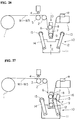
- Figures 30 and 31 schematically show a conventional apparatus for making electric harnesses. It includes a rising-and-descending roll unit 45, the roll 46 of which is lowered to pull down a length of wire stretched under tension and fed out of an associated wires supply reel 40 to measure the wire w in terms of the level at which the wire w is pulled down.
- a guide roll is indicated at 41
- a connector-carrier for supplying connectors R is indicated at 42
- a wire-clamping cylinder is indicated at 43
- a counter roll is indicated at 44.
- the apparatus is useful in measuring wires.
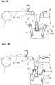
- it has the following deficiency.
- the roll 46 of the rising-and-descending roll unit 45 is allowed to rise to its original position, and then the pull-out wire w is released from tension.
- the part of the pull-out wire w extending from the roll 46 of the rising-and-descending roll unit 45 to the electric connector press-connected end is liable to curl.
- the curling prevents the rising of the rising-and-descending roll unit 45, and causes the tangling of wires. Accordingly the wire measuring and connector press-connecting cannot be performed at an increased efficiency.
- One object of the present invention is to provide a wire-length measuring apparatus which allows wires to descend naturally under gravity without curling after being released from tension subsequent to completion of wire measurement, thus assuring smooth rising of the roll unit and avoiding the tangling of the wires, and accordingly improving the efficiency with which electric harnesses are manufactured.
- a wire-length measuring apparatus including a rising-and-descending roll unit, the roll of which is lowered to pull down wires stretched under tension and each fed out of an associated wire supply reel to measure wires in terms of a different level at which the wires are pulled down, is improved according to the present invention in that: said roll unit has a lower roll to pull down wires and an upper roll spaced from said lower roll; and said apparatus further comprises a pinch roll unit which comprises at least one pinch roll to invade somewhat the area between said upper and lower rolls of said roll unit on the side opposite to the wire-supplying side before said lower roll start for wire measurement, thereby keeping the wire pushed against the surfaces of said upper and lower rolls just before the wire measurement is completed.
- the pinch roll invades somewhat the area between said upper and lower rolls of said roll unit on the side opposite to the wire-supplying side before said lower roll starts for wire measurement, that is, before the lower roll descends to a selected level, thereby keeping the wire pushed against the surfaces of the upper and lower rolls, and releasing the pinch roll just before the wire measurement is completed.
- the part of the wire length between the lower roll and the press-connected wire end is prevented from curling.
- Figures 1 to 17 show a wire-length measuring apparatus according to a first embodiment of the present invention.
- a description is given as to how the measuring of a plurality of wires, particularly five wires W1 to W5 may be effected.
- wire supply reels 1, wire-clamping cylinders 4, guide roller 2, and electric connector carrier 3 are allotted for different wires W1 to W5 to be measured respectively, and these components are arranged laterally at the same intervals as these wires.
- These parallel wire supply reels 1, the parallel wire-clamping cylinders 4 and a counter roller 5, the parallel guide roller 2 and the parallel electric connector carriers 3 are arranged in the order named longitudinally in the direction "A" in which the parallel wire supply reels 1 feed the wires W1 to W5.
- Figure 1 shows the wire-length measuring apparatus in condition that all wires W1 to W5 having electric connector R press-connected at their ends are stretched by moving the electric connector carrier 3 rightward and by stopping it at a predetermined position, thus extending all wires over a predetermined length. After the wire-feeding stops, a backward rotating force is applied to the wire supply reels 1 by appropriate spring means to stretch the wires W1 to W5 in tension.
- devices from press-connecting electric connector R to the ends of wires W1 to W5 are omitted for the sake of simplicity of drawing.
- a rising-and descending roller unit 6 is placed between the guide rolls 2 and a right fixed position to which the electric connector R is brought by the electric connector carrier 3.
- This roller unit 6 comprises a roller support 7, a lower roller 9 rotatably fixed to the roller support 7, and an upper roller 8 spaced a given distance from the lower roller 9 and fixed to the roller support 7.
- the lower roller 9 has grooves 17 made its circumference to receive the wires W1 to W5.
- a pinch roller unit 10 is positioned between the guide roller 2 and the right fixed position, opposite to the rising-and-descending roller unit 6. It comprises a rising-and-descending support 11 and two swingable arms 12 and 14. These arms 12 and 14 are swingably fixed to the support 11, and they have pinch rollers 13 and 15 at their ends. Some details of such pinch roll unit 10 are shown in Figures 14 and 15, and will be later described.
- the roller unit 6 is lowered to cause all wires W1 to W5 to yieldingly descend as indicated at B in Figures 3 and 4, thus starting the wire measurement.
- all wires W1 to W5 are fitted in the circumferential grooves 17 of the lower roller 9, and are pulled down.
- these descending wire form an angle of for instance, 60 degrees
- the pinch rollers 13 and 15 are moved longitudinally to come close to the two sides of the "V"-shaped descending wires as indicated at arrows C.
- the roller unit 6 continues descending as indicated by arrow D in Figures 5 and 6.
- the descending amount depends on a wire length to be determined.
- the pinch rollers 13 and 15 advance full distance forward, and the pinch roller unit 10 starts rising as indicated by arrow E.
- the pinch rollers 13 and 15 are released just before completion of the wire measurement.
- the swinging of the swingable arms may be controlled with the aid of cam plates 16.
- the pinch rollers 13 and 15 are retracted as indicated by arrows G just before completion of the longest wire measurement, and at the same time, the support 11 starts returning to the lower, original position as indicated by arrow H. After that, the roller unit 6 starts rising.
- All wires W1 to W5 are extended to the longest length L1, even though three W1, W2 and W3 of these wires. Then, the roller unit 6 rises as indicated by arrow J in Figure 11 until its lower roller 9 reaches the second lower level corresponding to the second longest length L2.
- the wires W1 to W3 to be measured for the second longest length L2 are withdrawn toward the associated wire supply reels 1 as indicated by arrow K, thereby performing the second longest wire measurement.
- the pinch roller 13 returns to its original position.
- the other pinch roller 15 remains in the same invading-and pushing position as before, as indicate by arrow M.
- the pinch roll 15 leaves the area between the upper and lower rolls 8 and 9 just before completion of wire measurement.
- Electric connectors L may be press-connected to the other or left ends of the longest and second longest wires, or the other or left ends of these wires may be left free of electric connectors.
- the operations of the pinch rollers 13 and 15 in determining different lengths L1 and L2 are described above. In determining a single wire from a given length or in determining a plurality of wires to be equal in length the pinch rollers 13 and 5 are apart from each other upon completion of a single required wire measurement, descending and returning backward to their original positions.
- Figures 14 shows one example of the roller unit as using a reversing motor 18 to raise or lover the roller unit body 6. Specifically, rotation of the motor 18 is transmitted to sprocket wheels 19 and 20 to cause rotation of an associated screw shaft 21 to raise or lower an associated rising-and-descending piece 22, thereby causing an associated support arm 23 to rise or descend, and accordingly permitting the upper and lower rolls 8 and 9 to rise or descend.
- This rising and descending may be effected smoothly thanks to a guide means 25 on a guide rail 24.
- the controlling of the descending distance to perform a required length measurement, and the controlling of rising and descending timing may be made by a control for the motor.
- a rising-and-descending cylinder 26 may be used in raising and lowering the pinch rollers 13 and 15. Specifically, the rising-and-descending of the cylinder 26 causes associated rising-and-descending plates 29 to rise and descend under the guidance of guide means 27 and 28, accordingly raising and lower the pinch rollers 13 and 15.
- a reciprocating cylinder 30 may be used in reciprocating the pinch rollers 13 and 15. Specifically, the pinch rolls 13 and 15 may be connected to the reciprocating cylinder 30 via a connecting rod 31. Other appropriate drive means may be used.
- a wire-length measuring apparatus according to a second embodiment is described.
- This apparatus is different from the first embodiment only in that: the second embodiment uses only one pinch roller 13 whereas the first embodiment uses two pinch rollers 13 and 15.
- the use of one pinch roller still has the effect of preventing the curling of the portions of the wires extending from the electric connector press-connected ends to the lower roller 9 of the roller unit 6.
- electric connector R is press-connected to the right ends of all wires W1 to W5, and then, the so press-connected electric connector R is carried in the right direction A by the electric connector carrier 3.
- the wire supply rolls 1 are rotated counterward to pull all wires W1 to W5 backward, thereby stretching these wires under tension.
- the roller unit 6 remains at the raised, original position whereas the pinch roller unit 10 remains at the lowered, original position, keeping its swingable arm 12 open, and hence keeping the pinch roller 13 withdrawn.
- the roller unit 6 is lowered to cause all wires W1 to W5 to yieldingly descend as indicated at B in Figure 19, thus starting the wire measurement.
- all wires W1 to W5 are fitted in the circumferential grooves 17 of the lower roller 9, and are pulled down.
- the roller unit 6 continues descending as indicated by arrow D in Figure 20.
- the descending amount depends on a wire length to be determined.
- the pinch roller 13 advances the full distance forward parallel to the axis of roller 13, and the pinch roller unit 10 starts rising as indicated by arrow E.
- all wires W1 to W5 are lowered to a lowest level corresponding to the longest length L1 by the roll 9.
- the swingable arm 12 rotates inward as indicated by arrow F in Figure 21 to permit the pinch roller 13 to invade somewhat the area between the upper and lower rollers 8 and 9 on one side of the roller unit 6.
- the pinch roller 13 is made to stop, exceeding one millimeter beyond the line extending tangentially along the upper and lower rollers 8 and 9 of the roller unit 6.
- electric connector R is press-connected to the right ends of all wires W1 to W5, and then, the so press-connected electric connector R is carried in the right direction A by the electric connector carrier 3.
- the wire supply rolls 1 are rotated counterward to pull all wires W1 to W5 backward, thereby stretching these wires under tension.
- the roll unit 6 remains as the upper, original position whereas the pinch roll unit 10 remains at the lower, original position, keeping its swingable arms 12 and 14 open, and hence keeping the pinch rollers 13 and 15 withdrawn.
- the roller unit 6 descends further as indicated by arrow D in Figure 26.
- the descending amount depends on the wire length to be determined.
- the pinch roller 13 advances full distance forward, and the pinch roller unit 10 starts rising as indicated by arrow E.
Landscapes
- Engineering & Computer Science (AREA)
- Manufacturing & Machinery (AREA)
- Manufacturing Of Electrical Connectors (AREA)
- A Measuring Device Byusing Mechanical Method (AREA)
Abstract
Description
- The present invention relates to a wire-length measuring apparatus, and more particularly to an improved wire-length measuring apparatus using rising-and-descending rolls.
- As is well know, electric harnesses whose insulated wires have electric connectors press-connected at one or both ends are used to connect one and another electric apparatuses. The insulated wires of such electric harnesses are of different lengths, and are selected to meet occasional length requirements. Accordingly apparatuses for making electric harnesses are designed to measure and cut desired lengths of insulated wires and press-connect electric connectors to one or both ends each of the so measured-and-cut insulated wires.
- Figures 30 and 31 schematically show a conventional apparatus for making electric harnesses. It includes a rising-and-descending
roll unit 45, theroll 46 of which is lowered to pull down a length of wire stretched under tension and fed out of an associatedwires supply reel 40 to measure the wire w in terms of the level at which the wire w is pulled down. In the drawings, a guide roll is indicated at 41, a connector-carrier for supplying connectors R is indicated at 42, a wire-clamping cylinder is indicated at 43, and a counter roll is indicated at 44. - The apparatus is useful in measuring wires. However, it has the following deficiency. As seen from Figure 31, after measuring the wire w, the
roll 46 of the rising-and-descendingroll unit 45 is allowed to rise to its original position, and then the pull-out wire w is released from tension. Then the part of the pull-out wire w extending from theroll 46 of the rising-and-descendingroll unit 45 to the electric connector press-connected end is liable to curl. Disadvantageously the curling prevents the rising of the rising-and-descendingroll unit 45, and causes the tangling of wires. Accordingly the wire measuring and connector press-connecting cannot be performed at an increased efficiency. - One object of the present invention is to provide a wire-length measuring apparatus which allows wires to descend naturally under gravity without curling after being released from tension subsequent to completion of wire measurement, thus assuring smooth rising of the roll unit and avoiding the tangling of the wires, and accordingly improving the efficiency with which electric harnesses are manufactured.
- To attain this and other objects a wire-length measuring apparatus including a rising-and-descending roll unit, the roll of which is lowered to pull down wires stretched under tension and each fed out of an associated wire supply reel to measure wires in terms of a different level at which the wires are pulled down, is improved according to the present invention in that: said roll unit has a lower roll to pull down wires and an upper roll spaced from said lower roll; and said apparatus further comprises a pinch roll unit which comprises at least one pinch roll to invade somewhat the area between said upper and lower rolls of said roll unit on the side opposite to the wire-supplying side before said lower roll start for wire measurement, thereby keeping the wire pushed against the surfaces of said upper and lower rolls just before the wire measurement is completed.
- With this improved arrangement the pinch roll invades somewhat the area between said upper and lower rolls of said roll unit on the side opposite to the wire-supplying side before said lower roll starts for wire measurement, that is, before the lower roll descends to a selected level, thereby keeping the wire pushed against the surfaces of the upper and lower rolls, and releasing the pinch roll just before the wire measurement is completed. The part of the wire length between the lower roll and the press-connected wire end is prevented from curling.
- Other objects and advantages of the present invention will be understood from the following description of harness manufacturing apparatuses according to preferred embodiments of the present invention, which are shown in accompanying drawings:
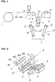
- Figure 1 schematically shows a wire-length measuring apparatus of the present invention, feeding a plurality of insulated wires each having an electric connector press-connected at its one end;
- Figure 2 is a perspective view of the measuring part of the wire-length measuring apparatus of Figure 1;
- Figure 3 schematically shows the wire-length measuring apparatus starting the measuring of the wires;
- Figure 4 is a perspective view of the measuring part of the wire-length measuring apparatus starting the measuring of the wires;
- Figure 5 schematically shows the wire-length measuring apparatus in the condition that its pinch rollers start rising;
- Figure 6 is a perspective view of the measuring part of the wire-length measuring apparatus in the condition of Figure 5;
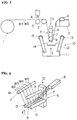
- Figure 7 schematically shows the wire-length measuring apparatus in the condition that its pinch rollers are in operating position, performing wire measurement for a longest length;
- Figure 8 is a perspective view of the measuring part of the wire-length measuring apparatus in the condition of Figure 7;
- Figure 9 schematically shows the wire-length measuring apparatus in the condition that its pinch rollers have returned to their original positions after completion of wire measurement for a longest length;
- Figure 10 is a perspective view of the measuring part of the wire-length measuring apparatus in the condition of Figure 9;
- Figure 11 schematically shows the wire-length measuring apparatus in the condition that its roller unit starts rising to the level at which a second longest length measurement is effected;
- Figure 12 is a perspective view of the measuring part of the wire-length measuring apparatus in the condition that selected wires have been withdrawn to the wire supply reels for a second longest measurement;
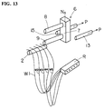
- Figure 13 is a perspective view of the measuring part of the wire-length measuring apparatus in the condition that measurements of all wires have been completed;
- Figure 14 is a front view of the roller unit and the pinch rollers in combination;
- Figure 15 is a left side view of the combination of Figure 14;
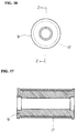
- Figure 16 is a front view of the lower roller of the rollers unit;
- Figure 17 is a longitudinal section of the lower roller taken along the line Z-Z in Figure 16;
- Figure 18 schematically shows a wire-length measuring apparatus according to a second embodiment prior to the starting of wire measurement;
- Figure 19 schematically shows the wire-length measuring apparatus of Figure 18 starting the measuring of the wires;
- Figure 20 schematically shows the wire-length measuring apparatus of Figure 18 in the condition that its roller unit starts to lower;
- Figure 21 schematically shows the wire-length measuring apparatus of Figure 18 in the condition that wire measurement is effected;
- Figure 22 schematically shows the wire-length measuring apparatus of Figure 18 in the condition that its pinch rollers return to their original positions;
- Figure 23 schematically shows the wire-length measuring apparatus of Figure 18 in the condition that its roller unit starts to rise to the level at which a second longest length measurement is effected;
- Figure 24 schematically shows a wire-length measuring apparatus according to a third embodiment prior to the start of wire measurement;
- Figure 25 schematically shows the wire-length measuring apparatus of Figure 24 starting to measure the wires;
- Figure 26 schematically shows the wire-length measuring apparatus of Figure 24 in the condition that its roller unit starts to lower;
- Figure 27 schematically shows the wire-length measuring apparatus of Figure 24 in the condition that wire measurement is effected;
- Figure 28 schematically shows the wire-length measuring apparatus of Figure 24 in the condition that its pinch rollers have returned to their original positions;
- Figure 29 schematically shows the wire-length measuring apparatus of Figure 24 in the condition that its roller unit starts to rise to the level at which a second longest length measurement is effected;
- Figure 30 schematically shows a conventional wire-length measuring apparatus of the prior art; and
- Figure 31 schematically shows how the prior art wire-length measuring apparatus causes the curling of the measured wires.
- Figures 1 to 17 show a wire-length measuring apparatus according to a first embodiment of the present invention. First, referring to Figure 1 to 13, a description is given as to how the measuring of a plurality of wires, particularly five wires W1 to W5 may be effected.
- Referring to Figure 1, wire supply reels 1, wire-
clamping cylinders 4,guide roller 2, andelectric connector carrier 3 are allotted for different wires W1 to W5 to be measured respectively, and these components are arranged laterally at the same intervals as these wires. These parallel wire supply reels 1, the parallel wire-clamping cylinders 4 and acounter roller 5, theparallel guide roller 2 and the parallelelectric connector carriers 3 are arranged in the order named longitudinally in the direction "A" in which the parallel wire supply reels 1 feed the wires W1 to W5. - Figure 1 shows the wire-length measuring apparatus in condition that all wires W1 to W5 having electric connector R press-connected at their ends are stretched by moving the
electric connector carrier 3 rightward and by stopping it at a predetermined position, thus extending all wires over a predetermined length. After the wire-feeding stops, a backward rotating force is applied to the wire supply reels 1 by appropriate spring means to stretch the wires W1 to W5 in tension. In these drawings, devices from press-connecting electric connector R to the ends of wires W1 to W5 are omitted for the sake of simplicity of drawing. - As seen from Figure 1, a rising-and descending
roller unit 6 is placed between theguide rolls 2 and a right fixed position to which the electric connector R is brought by theelectric connector carrier 3. Thisroller unit 6 comprises aroller support 7, alower roller 9 rotatably fixed to theroller support 7, and anupper roller 8 spaced a given distance from thelower roller 9 and fixed to theroller support 7. As seen from Figures 16 and 17, thelower roller 9 hasgrooves 17 made its circumference to receive the wires W1 to W5. - A
pinch roller unit 10 is positioned between theguide roller 2 and the right fixed position, opposite to the rising-and-descendingroller unit 6. It comprises a rising-and-descendingsupport 11 and twoswingable arms arms support 11, and they havepinch rollers pinch roll unit 10 are shown in Figures 14 and 15, and will be later described. - With reference to Figures 1 to 13 a series of measuring operations are described below. First, as shown in Figures 1 and 2, electric connector R is press-connected to the ends of all wires W1 to W5 by a press-connecting unit (not shown), and then, the so press-connected electric connector R is carried in the right direction A by the
electric connector carrier 3. After the feeding of all wires W1 to W5 stops, the wire supply rolls 1 are rotated counterward to pull all wires W1 to W5 backward, thereby stretching these wires under tension. In this condition theroller unit 6 remains at the raised, original position whereas thepinch roller unit 10 remains at the lowered, original position, keeping itsswingable arms - Then, the
roller unit 6 is lowered to cause all wires W1 to W5 to yieldingly descend as indicated at B in Figures 3 and 4, thus starting the wire measurement. Specifically, all wires W1 to W5 are fitted in thecircumferential grooves 17 of thelower roller 9, and are pulled down. When these descending wire form an angle of for instance, 60 degrees, thepinch rollers - The
roller unit 6 continues descending as indicated by arrow D in Figures 5 and 6. The descending amount depends on a wire length to be determined. Thepinch rollers pinch roller unit 10 starts rising as indicated by arrow E. - Now, assume that two wires W4 and W5 are determined for a longest length L1 and that three remaining wires W1, W2 and W3 are determined for a second longest length L2. First, all wires W1 to W5 are lowered to the lowest level corresponding to the longest length L1 by the
roller 9. Before starting the longest length wire measurement subsequent to the pulling-down of all wires to the lowest level, theswingable arms pinch rollers lower rolls 8 and 9 (for instance, 1 millimeter inside) on either side of theroller unit 6. - Thus, upon wire measurement all wires W1 to W5 are kept pushed against the upper and
lower rolls - The inventor found that the wire measurement effected in this condition has the effect of preventing the curling of wires between the
lower roller 9 and the electrical connector press-connected wire ends. Thepinch rollers cam plates 16. - As shown in Figures 9 and 10, the
pinch rollers support 11 starts returning to the lower, original position as indicated by arrow H. After that, theroller unit 6 starts rising. - All wires W1 to W5 are extended to the longest length L1, even though three W1, W2 and W3 of these wires. Then, the
roller unit 6 rises as indicated by arrow J in Figure 11 until itslower roller 9 reaches the second lower level corresponding to the second longest length L2. - As shown in Figure 12, the wires W1 to W3 to be measured for the second longest length L2 are withdrawn toward the associated wire supply reels 1 as indicated by arrow K, thereby performing the second longest wire measurement. The
pinch roller 13 returns to its original position. Theother pinch roller 15, however, remains in the same invading-and pushing position as before, as indicate by arrow M. Thus keeping the wires W1 to W3 pushed against the upper andlower rollers pinch roll 15 leaves the area between the upper andlower rolls - The longest and second longest measurements of all wires W1 to W5 are completed, and then, the
roller unit 6 rises as indicated by arrow N and the pinch rolls 13 and 15 return to their original positions P, as shown in Figure 13. - Electric connectors L (Figure 12) may be press-connected to the other or left ends of the longest and second longest wires, or the other or left ends of these wires may be left free of electric connectors.
- The operations of the
pinch rollers pinch rollers - Figures 14 shows one example of the roller unit as using a reversing
motor 18 to raise or lover theroller unit body 6. Specifically, rotation of themotor 18 is transmitted tosprocket wheels screw shaft 21 to raise or lower an associated rising-and-descendingpiece 22, thereby causing an associatedsupport arm 23 to rise or descend, and accordingly permitting the upper andlower rolls guide rail 24. - The controlling of the descending distance to perform a required length measurement, and the controlling of rising and descending timing may be made by a control for the motor.
- As shown in Figures 14 and 15, a rising-and-descending
cylinder 26 may be used in raising and lowering thepinch rollers cylinder 26 causes associated rising-and-descendingplates 29 to rise and descend under the guidance of guide means 27 and 28, accordingly raising and lower thepinch rollers reciprocating cylinder 30 may be used in reciprocating thepinch rollers reciprocating cylinder 30 via a connectingrod 31. Other appropriate drive means may be used. - Referring to Figures 18 to 23, a wire-length measuring apparatus according to a second embodiment is described. This apparatus is different from the first embodiment only in that: the second embodiment uses only one
pinch roller 13 whereas the first embodiment uses twopinch rollers lower roller 9 of theroller unit 6. - First, as shown in Figure 18, electric connector R is press-connected to the right ends of all wires W1 to W5, and then, the so press-connected electric connector R is carried in the right direction A by the
electric connector carrier 3. After the feeding of all wires W1 to W5 stops, the wire supply rolls 1 are rotated counterward to pull all wires W1 to W5 backward, thereby stretching these wires under tension. In this condition theroller unit 6 remains at the raised, original position whereas thepinch roller unit 10 remains at the lowered, original position, keeping itsswingable arm 12 open, and hence keeping thepinch roller 13 withdrawn. - Then, the
roller unit 6 is lowered to cause all wires W1 to W5 to yieldingly descend as indicated at B in Figure 19, thus starting the wire measurement. Specifically, all wires W1 to W5 are fitted in thecircumferential grooves 17 of thelower roller 9, and are pulled down. - The
roller unit 6 continues descending as indicated by arrow D in Figure 20. The descending amount depends on a wire length to be determined. Thepinch roller 13 advances the full distance forward parallel to the axis ofroller 13, and thepinch roller unit 10 starts rising as indicated by arrow E. - First, all wires W1 to W5 are lowered to a lowest level corresponding to the longest length L1 by the
roll 9. Before starting the longest length wire measurement subsequent to the pulling-down of all wires to the lowest level, theswingable arm 12 rotates inward as indicated by arrow F in Figure 21 to permit thepinch roller 13 to invade somewhat the area between the upper andlower rollers roller unit 6. For instance, thepinch roller 13 is made to stop, exceeding one millimeter beyond the line extending tangentially along the upper andlower rollers roller unit 6. - Thus, upon wire measurement, all wires W1 to W5 are kept pushed against the upper and
lower rollers pinch roller 13 on one side of theroller unit 6. - The inventor found that the wire measurement effected in this condition prevents the curling of wires between the
lower roller 9 and the electrical connector press-connected wires ends. Thepinch roller 13 is released just before completion of the wire measurement as seen from Figure 22. Then in the same way as the first embodiment, the wire-length measuring apparatus proceeds to the subsequent step as shown in Figure 23. - Referring to Figures 24 to 29, a wire-measuring apparatus according to a third embodiment of the present invention is described below. It is a modification of the first embodiment, and is appropriate for the purpose of measuring different wire lengths. Specifically, when the
lower roller 9 starts rising for measuring a subsequent shorter wire length sequential to completion of a preceding wire measurement, and when some wires selected to be measured subsequently are withdrawn toward the wire supply reels 1, thepinch roller 15 is put in contact with theupper roll 8 to push the selected wire which are being pulled back. - As is the case with the first or second embodiment, electric connector R is press-connected to the right ends of all wires W1 to W5, and then, the so press-connected electric connector R is carried in the right direction A by the
electric connector carrier 3. After the feeding of all wires W1 to W5 stops, the wire supply rolls 1 are rotated counterward to pull all wires W1 to W5 backward, thereby stretching these wires under tension. In this condition theroll unit 6 remains as the upper, original position whereas thepinch roll unit 10 remains at the lower, original position, keeping itsswingable arms pinch rollers - Then, the
roller unit 6 is lowered to cause all wires W1 to W5 to yieldingly descend as indicated at B in Figure 25, thus starting the wire measurement. Specifically, all wires W1 to W5 are fitted in thecircumferential grooves 17 of thelower roller 9, and are pulled down. - The
roller unit 6 descends further as indicated by arrow D in Figure 26. The descending amount depends on the wire length to be determined. Thepinch roller 13 advances full distance forward, and thepinch roller unit 10 starts rising as indicated by arrow E. - Assume that two wires W4 and W5 are to be the longest length L1 and that three wires W1, W2 and W3 are to be a second shorter length L2. First, all wires W1 to W5 are lowered to a lowest level corresponding to the longest length L1 by the
roller 9. Before completing the longest length wire measurement, only theswingable arm 12 rotates inward as indicated by arrow F in Figure 27 to permit thepinch roller 13 to invade somewhat the area between the upper andlower rollers roller unit 6. Thus, all wires are pushed against the upper andlower rollers pinch roller 13. At this time, theother pinch roller 15 remains spaced apart from theroller unit 6. Just before completion of the longest wire measurement thepinch roller 13 is withdrawn as indicated by arrow G in Figure 28. - When the second longest wire measurement is performed on the wires W1 to W3, the
lower rollers 9 of theroller unit 6 rises to a level corresponding to the second longest length L2 as indicated by arrow J in Figure 29. Then, the wires W1 to W3 are withdrawn toward the wire supply reels 1 as indicated by arrow K to determine the second longest length L2. During this withdrawal thepinch roller 15 is moved into contact with theupper roller 8, pushing the withdrawn wires W1 to W3 against theupper roller 8. Thus, the curling of these wires are prevented. The apparatus otherwise works sequentially in the same way as the first embodiment. - As may be understood from the above, the wires to be measured can be advantageously prevented from curling in the course of measurement.
Claims (15)
- In an apparatus for making electrical harness having a plurality of wires (W1-W5) and at least one electrical connector (R) at a first end of said plurality of wires, said apparatus including:
an apparatus (1) for supplying a plurality of wires along a first path;
means (3) for supporting an electrical connector;
means for guiding said wires between said wire supply apparatus and said electrical connector;
looper means (6) movable along a second path in a direction generally perpendicular to said first path and including a lower wire engaging surface adjacent the bottom of said looper means to engage said wires in order to push a portion of said wires downward to establish the longest length wire of said plurality of wires; and
means (18-25) for moving said looper means along said second path in a direction generally perpendicular to said first path;
characterized in that:
said looper means further includes an upper arcuate surface (8) spaced from and positioned above said
lower wire engaging surface;
a first pinch member (13) reciprocally movable between a remote first position spaced from said wires and a wire engaging second position, said wire engaging second position being located adjacent one of said lower wire engaging surface and said upper arcuate surface of said looper means to force at least some of said wires into engagement with said first pinch member and one of said lower wire engaging surface and said upper arcuate surface; and
means (26-30) for moving said first pinch member between said remote first position and said wire engaging second position. - The apparatus of claim 1 wherein said lower wire engaging surface is arcuate.
- The apparatus of claim 2 wherein said lower wire engaging surface is located on a first roller (9) rotatably mounted on a portion of said looper means.
- The apparatus of claim 3 wherein said upper arcuate surface is a second roller (8) rotatably mounted on a portion of said looper means above said first roller.
- The apparatus of claim 4 wherein said first pinch member is a first pinch roller (13) rotatably mounted on said apparatus.
- The apparatus of claim 4 further including a second pinch member (15) reciprocally movable between a remote third position spaced from said wires and a wire engaging fourth position, said first pinch member being located adjacent said first roller when positioned at said wire engaging second position to force at least some of said wires into engagement with said first pinch member and said first roller, and said second pinch member being located adjacent said second roller when positioned at said wire engaging fourth position to force at least some of said wires into engagement with said second pinch member and said second roller.
- The apparatus of claim 6 wherein said second pinch member is a second pinch roller (15) rotatably mounted on said apparatus.
- The apparatus of claim 1 further including a second pinch member (15) reciprocally movable between a remote third position spaced from said wires and a wire engaging fourth position adjacent said second path, said first pinch member being located adjacent said lower wire engaging surface when positioned at said wire engaging second position to force at least some of said wires into engagement with said first pinch member and said lower wire engaging surface, and said second pinch member being located adjacent said second roller when positioned at said wire engaging fourth position to force at least some of said wires into engagement with said second pinch member and said upper arcuate surface.
- The apparatus of claim 1 wherein said upper arcuate surface is a roller rotatably mounted on a portion of said looper means above said lower wire engaging surface.
- The apparatus of claim 1 wherein said first pinch member is a first pinch roller rotatably mounted on said apparatus.
- The apparatus of claim 1 wherein said upper arcuate surface is offset to one side of said second path relative to said lower wire engaging surface.
- The apparatus of claim 1 wherein said lower wire engaging surface is located on a first arcuate roller rotatably mounted on a portion of said looper means, said upper arcuate surface is a second roller rotatably mounted on a portion of said looper means above said first roller, said first pinch member is a first pinch roller rotatably mounted on said apparatus and further includes a second pinch member reciprocally movable between a remote third position spaced from said wires and a wire engaging fourth position, said first pinch member being located adjacent said first roller when positioned at said wire engaging second position to force at least some of said wires into engagement with said first pinch member and said first roller and said second pinch member being located adjacent said second roller when positioned at said wire engaging fourth position to force at least some of said wires into engagement with said second pinch member and said second roller.
- The apparatus of claim 1 wherein said lower wire engaging surface is arcuate and said apparatus further includes a second pinch member reciprocally movable between a remote third position spaced from said wires and a wire engaging fourth position adjacent said second path, said first pinch member being located adjacent said first roller when positioned at said wire engaging second position to force at least some of said wires into engagement with said first pinch member and said lower wire engaging surface, and said second pinch member being located adjacent said upper arcuate surface when positioned at said wire engaging fourth position to force at least some of said wires into engagement with said second pinch member and said upper arcuate surface.
- A method of manufacturing an electrical harness having a plurality of wires (W1-W5) and at least one electrical connector (R) at a first end of said plurality of wires, said method including the steps of:
providing an electrical connector (R);
providing a plurality of wires (W1-W5) along a first path from a wire supply source (1);
terminating said plurality of wires to said electrical connector;
means (3) for supporting an electrical connector;
moving a looper means (6) along a second path in a direction generally perpendicular to said first path between and upper position and a lower position to engage said wires with a lower wire engaging surface (9) adjacent the bottom of said looper means to lengthen the amount of wire between said connector and said wire supply source;
moving a first pinch member (13) into engagement with said wires to force at least some of said wires into engagement with one of said lower wire engaging surface and an upper arcuate surface (8) spaced from and positioned above said lower wire engaging surface while said looper means is moved along its second path; and
moving said looper means upward along said second path to its upper position. - The method of claim 14 further comprising moving a second pinch member (15) laterally into engagement with said wires to force at least some of said wires into engagement with said upper arcuate surface while said looper means is moved upward along its second path to its upper position and at least some of said plurality of wires are retracted along said first path.
Applications Claiming Priority (3)
| Application Number | Priority Date | Filing Date | Title |
|---|---|---|---|
| JP90238/92 | 1992-03-16 | ||
| JP9023892U | 1992-12-08 | ||
| JP1992090238U JP2531112Y2 (en) | 1992-12-08 | 1992-12-08 | Wire length measuring device |
Publications (3)
| Publication Number | Publication Date |
|---|---|
| EP0601474A2 true EP0601474A2 (en) | 1994-06-15 |
| EP0601474A3 EP0601474A3 (en) | 1995-11-22 |
| EP0601474B1 EP0601474B1 (en) | 2000-05-31 |
Family
ID=13992919
Family Applications (1)
| Application Number | Title | Priority Date | Filing Date |
|---|---|---|---|
| EP93119408A Expired - Lifetime EP0601474B1 (en) | 1992-12-08 | 1993-12-02 | Wire-length measuring apparatus |
Country Status (6)
| Country | Link |
|---|---|
| US (1) | US5673475A (en) |
| EP (1) | EP0601474B1 (en) |
| JP (1) | JP2531112Y2 (en) |
| KR (1) | KR970005772B1 (en) |
| DE (1) | DE69328763T2 (en) |
| TW (1) | TW253938B (en) |
Cited By (1)
| Publication number | Priority date | Publication date | Assignee | Title |
|---|---|---|---|---|
| US5483738A (en) * | 1993-04-12 | 1996-01-16 | Molex Incorporated | Apparatus for making electrical harness having wire measuring apparatus equipped with anti-curling means |
Families Citing this family (4)
| Publication number | Priority date | Publication date | Assignee | Title |
|---|---|---|---|---|
| US6230404B1 (en) * | 1996-05-09 | 2001-05-15 | Sumitomo Wiring Systems, Ltd. | Method and apparatus for producing a wiring harness |
| WO2008143615A1 (en) * | 2007-05-21 | 2008-11-27 | Oxford Superconducting Technology | Improved device and method for internal flaw magnification or removal during wire drawing |
| JP6404719B2 (en) * | 2015-01-14 | 2018-10-17 | 矢崎総業株式会社 | Electric wire feeder |
| CN110364905B (en) * | 2019-08-06 | 2020-12-08 | 安徽九工电子设备有限公司 | Terminal machine with peeling and branching functions and working method thereof |
Citations (2)
| Publication number | Priority date | Publication date | Assignee | Title |
|---|---|---|---|---|
| US4370806A (en) * | 1979-02-16 | 1983-02-01 | Molex Incorporated | Electrical harness fabrication apparatus |
| US4551893A (en) * | 1983-07-05 | 1985-11-12 | Amp Incorporated | Wire processing apparatus |
Family Cites Families (7)
| Publication number | Priority date | Publication date | Assignee | Title |
|---|---|---|---|---|
| US4235015A (en) * | 1979-02-16 | 1980-11-25 | Molex Incorporated | Electrical harness fabrication method and apparatus |
| US4253222A (en) * | 1979-08-06 | 1981-03-03 | Methode Electronics, Inc. | Apparatus for applying assembled connector terminals to a plurality of leads |
| US4404743A (en) * | 1981-05-26 | 1983-09-20 | Amp Incorporated | Electrical harness fabrication using improved wire measuring method |
| JPS60117583A (en) * | 1983-11-29 | 1985-06-25 | 日本圧着端子製造株式会社 | Wire length evaluating device in automatic pressure welding machine |
| US4979292A (en) * | 1987-11-25 | 1990-12-25 | Sumitomo Wiring Systems, Ltd. | Method of forming filament harness |
| GB9001978D0 (en) * | 1990-01-29 | 1990-03-28 | Amp Gmbh | Wire spreading device |
| JP2808976B2 (en) * | 1992-03-02 | 1998-10-08 | 住友電装株式会社 | Harness manufacturing apparatus and harness manufacturing method |
-
1992
- 1992-12-08 JP JP1992090238U patent/JP2531112Y2/en not_active Expired - Lifetime
-
1993
- 1993-11-24 TW TW082109906A patent/TW253938B/zh active
- 1993-12-02 EP EP93119408A patent/EP0601474B1/en not_active Expired - Lifetime
- 1993-12-02 DE DE69328763T patent/DE69328763T2/en not_active Expired - Fee Related
- 1993-12-02 US US08/161,846 patent/US5673475A/en not_active Expired - Lifetime
- 1993-12-07 KR KR1019930026673A patent/KR970005772B1/en not_active IP Right Cessation
Patent Citations (2)
| Publication number | Priority date | Publication date | Assignee | Title |
|---|---|---|---|---|
| US4370806A (en) * | 1979-02-16 | 1983-02-01 | Molex Incorporated | Electrical harness fabrication apparatus |
| US4551893A (en) * | 1983-07-05 | 1985-11-12 | Amp Incorporated | Wire processing apparatus |
Cited By (1)
| Publication number | Priority date | Publication date | Assignee | Title |
|---|---|---|---|---|
| US5483738A (en) * | 1993-04-12 | 1996-01-16 | Molex Incorporated | Apparatus for making electrical harness having wire measuring apparatus equipped with anti-curling means |
Also Published As
| Publication number | Publication date |
|---|---|
| JP2531112Y2 (en) | 1997-04-02 |
| US5673475A (en) | 1997-10-07 |
| EP0601474A3 (en) | 1995-11-22 |
| KR940016296A (en) | 1994-07-22 |
| EP0601474B1 (en) | 2000-05-31 |
| DE69328763T2 (en) | 2001-01-25 |
| KR970005772B1 (en) | 1997-04-19 |
| DE69328763D1 (en) | 2000-07-06 |
| TW253938B (en) | 1995-08-11 |
| JPH0650287U (en) | 1994-07-08 |
Similar Documents
| Publication | Publication Date | Title |
|---|---|---|
| US4235015A (en) | Electrical harness fabrication method and apparatus | |
| US5230147A (en) | Electrical hardness termination apparatus and method | |
| US4126935A (en) | Method and apparatus for manufacturing wiring harnesses | |
| US4646404A (en) | Apparatus for manufacturing electrical harnesses | |
| KR910000620B1 (en) | Wire processing apparatus | |
| JPS60117583A (en) | Wire length evaluating device in automatic pressure welding machine | |
| US4107838A (en) | Arranging randomly positioned articles into preselected positions | |
| US4370806A (en) | Electrical harness fabrication apparatus | |
| US4976294A (en) | Method and apparatus for making specified-length wires for wire harness | |
| US5943751A (en) | Wire end alignment assembly for wire crimping apparatus | |
| JPS6213770B2 (en) | ||
| EP0601474B1 (en) | Wire-length measuring apparatus | |
| US5205329A (en) | Wire harness and method of and apparatus for manufacturing the same | |
| US4253222A (en) | Apparatus for applying assembled connector terminals to a plurality of leads | |
| US5933932A (en) | Apparatus for making electrical harness | |
| US5483738A (en) | Apparatus for making electrical harness having wire measuring apparatus equipped with anti-curling means | |
| JPH10507300A (en) | Apparatus and method for manufacturing electric harness | |
| US4534098A (en) | Apparatus for applying assembled connector terminals and the like to a plurality of leads | |
| EP0467593A1 (en) | Method and apparatus for processing a plurality of wire leads | |
| JPH06102228B2 (en) | Wire feeder | |
| JPS6236331B2 (en) | ||
| JPH04171614A (en) | Manufacturing device for cross inductive wire and manufacture thereof | |
| JPH10212067A (en) | Electric wire feed mechanism in electric wire machining equipment | |
| JPH09115344A (en) | Flat wire for wire harness and manufacture thereof | |
| JPS647468B2 (en) |
Legal Events
| Date | Code | Title | Description |
|---|---|---|---|
| PUAI | Public reference made under article 153(3) epc to a published international application that has entered the european phase |
Free format text: ORIGINAL CODE: 0009012 |
|
| AK | Designated contracting states |
Kind code of ref document: A2 Designated state(s): DE FR GB IT |
|
| PUAL | Search report despatched |
Free format text: ORIGINAL CODE: 0009013 |
|
| AK | Designated contracting states |
Kind code of ref document: A3 Designated state(s): DE FR GB IT |
|
| 17P | Request for examination filed |
Effective date: 19960424 |
|
| 17Q | First examination report despatched |
Effective date: 19980626 |
|
| GRAG | Despatch of communication of intention to grant |
Free format text: ORIGINAL CODE: EPIDOS AGRA |
|
| GRAG | Despatch of communication of intention to grant |
Free format text: ORIGINAL CODE: EPIDOS AGRA |
|
| GRAH | Despatch of communication of intention to grant a patent |
Free format text: ORIGINAL CODE: EPIDOS IGRA |
|
| GRAH | Despatch of communication of intention to grant a patent |
Free format text: ORIGINAL CODE: EPIDOS IGRA |
|
| GRAA | (expected) grant |
Free format text: ORIGINAL CODE: 0009210 |
|
| AK | Designated contracting states |
Kind code of ref document: B1 Designated state(s): DE FR GB IT |
|
| ITF | It: translation for a ep patent filed | ||
| REF | Corresponds to: |
Ref document number: 69328763 Country of ref document: DE Date of ref document: 20000706 |
|
| ET | Fr: translation filed | ||
| PLBE | No opposition filed within time limit |
Free format text: ORIGINAL CODE: 0009261 |
|
| STAA | Information on the status of an ep patent application or granted ep patent |
Free format text: STATUS: NO OPPOSITION FILED WITHIN TIME LIMIT |
|
| 26N | No opposition filed | ||
| PGFP | Annual fee paid to national office [announced via postgrant information from national office to epo] |
Ref country code: FR Payment date: 20011203 Year of fee payment: 9 |
|
| REG | Reference to a national code |
Ref country code: GB Ref legal event code: IF02 |
|
| PG25 | Lapsed in a contracting state [announced via postgrant information from national office to epo] |
Ref country code: FR Free format text: LAPSE BECAUSE OF NON-PAYMENT OF DUE FEES Effective date: 20030901 |
|
| REG | Reference to a national code |
Ref country code: FR Ref legal event code: ST |
|
| PGFP | Annual fee paid to national office [announced via postgrant information from national office to epo] |
Ref country code: GB Payment date: 20031105 Year of fee payment: 11 |
|
| PGFP | Annual fee paid to national office [announced via postgrant information from national office to epo] |
Ref country code: DE Payment date: 20031230 Year of fee payment: 11 |
|
| PG25 | Lapsed in a contracting state [announced via postgrant information from national office to epo] |
Ref country code: GB Free format text: LAPSE BECAUSE OF NON-PAYMENT OF DUE FEES Effective date: 20041202 |
|
| PG25 | Lapsed in a contracting state [announced via postgrant information from national office to epo] |
Ref country code: DE Free format text: LAPSE BECAUSE OF NON-PAYMENT OF DUE FEES Effective date: 20050701 |
|
| GBPC | Gb: european patent ceased through non-payment of renewal fee |
Effective date: 20041202 |
|
| PG25 | Lapsed in a contracting state [announced via postgrant information from national office to epo] |
Ref country code: IT Free format text: LAPSE BECAUSE OF NON-PAYMENT OF DUE FEES;WARNING: LAPSES OF ITALIAN PATENTS WITH EFFECTIVE DATE BEFORE 2007 MAY HAVE OCCURRED AT ANY TIME BEFORE 2007. THE CORRECT EFFECTIVE DATE MAY BE DIFFERENT FROM THE ONE RECORDED. Effective date: 20051202 |