WO2023063208A1 - イメージセンサデータ制御システム - Google Patents
イメージセンサデータ制御システム Download PDFInfo
- Publication number
- WO2023063208A1 WO2023063208A1 PCT/JP2022/037427 JP2022037427W WO2023063208A1 WO 2023063208 A1 WO2023063208 A1 WO 2023063208A1 JP 2022037427 W JP2022037427 W JP 2022037427W WO 2023063208 A1 WO2023063208 A1 WO 2023063208A1
- Authority
- WO
- WIPO (PCT)
- Prior art keywords
- image sensor
- sensor data
- spatial region
- real space
- unit
- Prior art date
Links
- 230000003068 static effect Effects 0.000 claims abstract description 41
- 230000005540 biological transmission Effects 0.000 claims description 24
- 230000004931 aggregating effect Effects 0.000 claims description 20
- 230000008859 change Effects 0.000 claims description 19
- 230000002123 temporal effect Effects 0.000 claims description 17
- 230000002194 synthesizing effect Effects 0.000 claims description 8
- 238000010586 diagram Methods 0.000 description 5
- 238000010801 machine learning Methods 0.000 description 3
- 238000000034 method Methods 0.000 description 3
- 238000001514 detection method Methods 0.000 description 2
- 238000005516 engineering process Methods 0.000 description 2
- 230000004907 flux Effects 0.000 description 2
- 238000012545 processing Methods 0.000 description 2
- 230000001737 promoting effect Effects 0.000 description 2
- 230000002776 aggregation Effects 0.000 description 1
- 238000004220 aggregation Methods 0.000 description 1
- 238000004891 communication Methods 0.000 description 1
- 238000011161 development Methods 0.000 description 1
- 230000000694 effects Effects 0.000 description 1
- 238000009499 grossing Methods 0.000 description 1
- 238000012986 modification Methods 0.000 description 1
- 230000004048 modification Effects 0.000 description 1
- 238000007637 random forest analysis Methods 0.000 description 1
- 230000009466 transformation Effects 0.000 description 1
Images


Classifications
-
- G—PHYSICS
- G06—COMPUTING; CALCULATING OR COUNTING
- G06T—IMAGE DATA PROCESSING OR GENERATION, IN GENERAL
- G06T7/00—Image analysis
-
- G—PHYSICS
- G01—MEASURING; TESTING
- G01S—RADIO DIRECTION-FINDING; RADIO NAVIGATION; DETERMINING DISTANCE OR VELOCITY BY USE OF RADIO WAVES; LOCATING OR PRESENCE-DETECTING BY USE OF THE REFLECTION OR RERADIATION OF RADIO WAVES; ANALOGOUS ARRANGEMENTS USING OTHER WAVES
- G01S13/00—Systems using the reflection or reradiation of radio waves, e.g. radar systems; Analogous systems using reflection or reradiation of waves whose nature or wavelength is irrelevant or unspecified
- G01S13/88—Radar or analogous systems specially adapted for specific applications
- G01S13/93—Radar or analogous systems specially adapted for specific applications for anti-collision purposes
- G01S13/931—Radar or analogous systems specially adapted for specific applications for anti-collision purposes of land vehicles
-
- G—PHYSICS
- G01—MEASURING; TESTING
- G01S—RADIO DIRECTION-FINDING; RADIO NAVIGATION; DETERMINING DISTANCE OR VELOCITY BY USE OF RADIO WAVES; LOCATING OR PRESENCE-DETECTING BY USE OF THE REFLECTION OR RERADIATION OF RADIO WAVES; ANALOGOUS ARRANGEMENTS USING OTHER WAVES
- G01S17/00—Systems using the reflection or reradiation of electromagnetic waves other than radio waves, e.g. lidar systems
- G01S17/88—Lidar systems specially adapted for specific applications
- G01S17/89—Lidar systems specially adapted for specific applications for mapping or imaging
-
- G—PHYSICS
- G05—CONTROLLING; REGULATING
- G05D—SYSTEMS FOR CONTROLLING OR REGULATING NON-ELECTRIC VARIABLES
- G05D1/00—Control of position, course, altitude or attitude of land, water, air or space vehicles, e.g. using automatic pilots
- G05D1/02—Control of position or course in two dimensions
-
- G—PHYSICS
- G06—COMPUTING; CALCULATING OR COUNTING
- G06T—IMAGE DATA PROCESSING OR GENERATION, IN GENERAL
- G06T7/00—Image analysis
- G06T7/20—Analysis of motion
- G06T7/215—Motion-based segmentation
-
- G—PHYSICS
- G08—SIGNALLING
- G08G—TRAFFIC CONTROL SYSTEMS
- G08G1/00—Traffic control systems for road vehicles
- G08G1/16—Anti-collision systems
-
- G—PHYSICS
- G16—INFORMATION AND COMMUNICATION TECHNOLOGY [ICT] SPECIALLY ADAPTED FOR SPECIFIC APPLICATION FIELDS
- G16Y—INFORMATION AND COMMUNICATION TECHNOLOGY SPECIALLY ADAPTED FOR THE INTERNET OF THINGS [IoT]
- G16Y10/00—Economic sectors
- G16Y10/40—Transportation
-
- G—PHYSICS
- G16—INFORMATION AND COMMUNICATION TECHNOLOGY [ICT] SPECIALLY ADAPTED FOR SPECIFIC APPLICATION FIELDS
- G16Y—INFORMATION AND COMMUNICATION TECHNOLOGY SPECIALLY ADAPTED FOR THE INTERNET OF THINGS [IoT]
- G16Y20/00—Information sensed or collected by the things
- G16Y20/20—Information sensed or collected by the things relating to the thing itself
-
- G—PHYSICS
- G16—INFORMATION AND COMMUNICATION TECHNOLOGY [ICT] SPECIALLY ADAPTED FOR SPECIFIC APPLICATION FIELDS
- G16Y—INFORMATION AND COMMUNICATION TECHNOLOGY SPECIALLY ADAPTED FOR THE INTERNET OF THINGS [IoT]
- G16Y40/00—IoT characterised by the purpose of the information processing
- G16Y40/10—Detection; Monitoring
Definitions
- the present invention relates to an image sensor data control system that controls image sensor data acquired in real space.
- Shibaura Institute of Technology the applicant of this application, is also promoting the concept of a "next-use future city" as part of its smart city.
- various stakeholders such as residents, workers, and visitors, and in the growing Toyosu area of Tokyo, we will provide service solutions in various fields by utilizing advanced technology and city OS.
- millimeter wave radar is a device that emits radio waves with a frequency of 30 GHz to 300 GHz called millimeter waves and measures their reflection. It is difficult to detect objects that are not very high and have low radio wave reflectance, such as trees.
- LiDAR light detection and ranging
- This LiDAR is a type of sensor that uses laser light. Compared to radio waves, the density of the radiant flux is higher than that of radio waves. , to accurately detect the position and shape of an object. Therefore, if LiDAR is used in a real space where static objects such as walls and dynamic objects such as automobiles exist, 3D information of the real space can be obtained as image sensor data consisting of point clouds of laser light. .
- Non-Patent Document 1 in addition to the LiDAR installed in the autonomous vehicle, the use of LiDAR placed in the surrounding environment such as traffic lights on the road side and on the street allows these to transmit image sensor data to the autonomous vehicle, thereby eliminating blind spots on the road. The situation and danger can be notified (for example, see Non-Patent Document 1).
- LiDAR acquires 3D information in real space in real time
- the amount of data will be enormous.
- Prioritizing image sensor data of dynamic objects such as humans that change over time is effective in data control.
- Such problems are not limited to LiDAR, but also occur in other sensors that acquire image sensor data consisting of point clouds.
- the applicant of the present invention has been made in view of the above-mentioned technical background, and has proposed an image sensor data system capable of controlling the priority of image sensor data in each spatial region related to static objects and dynamic objects in real space.
- the object is to provide a control system.
- the present invention provides image sensor data control in which one or more terminal devices and a server device are connected in a communicable state, and image sensor data acquired by each terminal device is controlled by the server device.
- the terminal device includes a sensor unit that acquires image sensor data composed of point clouds in real space, and transmits the image sensor data composed of point clouds in real space acquired by the sensor unit to the server device.
- the server device includes a reception unit that receives image sensor data consisting of a point cloud in real space transmitted from each terminal device, and a real space received by the reception unit an aggregating unit for aggregating image sensor data consisting of point clouds; and based on the image sensor data consisting of point clouds in real space aggregated by the aggregating unit, a static object or a dynamic object in each space area in real space.
- a learning unit that learns a movement feature index of image sensor data in each spatial region in real space, and a movement feature index of image sensor data in each spatial region in real space that is learned by the learning unit, which indicates features related to movement. and each space in real space based on the information about the movement feature index of the image sensor data of each spatial region in real space stored in the movement feature index information storage unit. and a control unit for setting the priority of the image sensor data of the area.
- a plurality of the terminal devices are provided so as to acquire image sensor data composed of point groups from different directions with respect to the same real space, and the aggregating unit comprises an image composed of point clouds acquired by each terminal device. You may aggregate by synthesizing sensor data chronologically.
- the learning unit may use the number of point groups of image sensor data in each spatial region in the real space as the movement feature index.
- the learning unit may determine a spatial region related to a static object or a dynamic object by learning temporal changes in movement feature indices of image sensor data of each spatial region in real space.
- the learning unit determines that the spatial region relates to a static object. If the deviation of the movement feature index of the image sensor data in the spatial region is outside a predetermined range, it may be determined that the spatial region is associated with a dynamic object.
- the learning unit determines that there are many dynamic objects moving in the spatial region when the average of the moving feature indices of the image sensor data of the predetermined spatial region in the real space exceeds a predetermined threshold value. If the average of the movement feature indices of the data is equal to or less than a predetermined threshold, it may be determined that there are few dynamic objects moving in the spatial region.
- control unit sets a high priority for the image sensor data of the spatial region determined by the learning unit to be a dynamic object, while the spatial region determined by the learning unit to be a static object.
- priority of the image sensor data may be set low.
- control unit sets a high priority for image sensor data in a spatial region determined by the learning unit to have many moving dynamic objects, while the learning unit determines that there are few moving dynamic objects.
- a lower priority may be set for the image sensor data in the spatial region that has been identified.
- the terminal device if the rate of change within a predetermined time of the movement feature index of the image sensor data in a predetermined spatial region in the real space exceeds a predetermined threshold, It is determined that the moving speed of the dynamic object in the spatial region is fast, and the priority of the image sensor data in the spatial region is set high. If the speed of change in time is equal to or less than a predetermined threshold, it may be determined that the moving speed of the dynamic object in the spatial region is slow, and the priority of the image sensor data in the spatial region may be set low.
- a server-side transmission unit is provided on the output side of the aggregating unit, and the control unit transmits image sensor data of a spatial region set with a high priority to the image sensor data acquired in real time by the terminal device.
- the server-side transmission unit may be controlled so as to preferentially transmit to a predetermined mobile unit.
- control unit preferentially transmits image sensor data of a spatial region, for which a high priority is set, to the predetermined server device with respect to the image sensor data acquired in real time by the terminal device within a predetermined period of time. You may control the said terminal side transmission part so that.
- the terminal-side transmission unit receives in advance the priority of the image sensor data of each spatial region from the server device, and preferentially transmits the image sensor data of the spatial region set with a high priority to the server device. You may
- the real space may be composed of a plurality of cells arranged in a grid as a spatial area, and the control unit may set the priority of the image sensor data for each cell.
- the priority of image sensor data of each spatial region related to a static object or a dynamic object in real space is obtained by learning the movement feature index of image sensor data composed of point clouds acquired in real space. can be set. For this reason, for spatial areas where the priority of image sensor data is set high (mainly spatial areas related to dynamic objects), real-time image sensor data is preferentially transmitted to moving objects, etc., while image sensor data Spatial regions with low priority (primarily static objects) may not be sent to the moving object of real-time image sensor data, or may be sent with a delay. Therefore, according to the priority of the image sensor data of each spatial area in the real space, the image sensor data acquired in real time by the terminal device can be transmitted to the mobile object for each spatial area. It is possible to quickly inform the driver of the blind spot situation and danger.
- FIG. 1 is a block diagram showing the configuration of an image sensor data control system according to an embodiment of this system
- FIG. 2 is a block diagram showing the configuration of the server device in FIG. 1
- FIG. It is a figure which shows the virtual three-dimensional real space.
- FIG. 4 is a diagram showing an example of image sensor data by LiDAR(a);
- FIG. 4 is a diagram showing an example of image sensor data by LiDAR(b);
- FIG. 4 is a diagram showing an example of synthesizing image sensor data from LiDAR(a) and image sensor data from LiDAR(b);
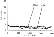
- 4 is a graph showing temporal changes in the number of point clouds of image sensor data obtained by LiDAR(a).
- 4 is a graph showing temporal changes in the number of point groups obtained by synthesizing image sensor data from LiDAR(a) and image sensor data from LiDAR(b).
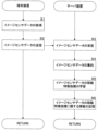
- 4 is a flow chart showing the flow of image sensor data learning by this system.
- 4 is a flow chart showing the flow of image sensor data priority setting by this system.
- 4 shows a virtual real space according to Example 1 of the present invention
- FIG. 11 shows a virtual real space according to Example 2 of the present invention
- FIG. FIG. 11 shows a virtual real space according to Example 3 of the present invention
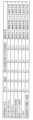
- FIG. 10 is a table showing trends of movement feature indices of image sensor data in each space area in a virtual real space according to Example 3 of the present invention;
- FIG. 1 An image sensor data control system (hereinafter referred to as the present system) according to an embodiment of the present invention will be described with reference to FIGS. 1 to 10.
- FIG. 1 An image sensor data control system (hereinafter referred to as the present system) according to an embodiment of the present invention will be described with reference to FIGS. 1 to 10.
- FIG. 1 An image sensor data control system (hereinafter referred to as the present system) according to an embodiment of the present invention will be described with reference to FIGS. 1 to 10.
- the server device 2 controls the image sensor data in the real space, and the real-time image sensor data in each spatial region of the real space is transmitted to the moving body 3 (for example, an automatic driving car, etc.) via a network or the like.
- the moving body 3 for example, an automatic driving car, etc.
- Real space refers to mainly three-dimensional spaces that actually exist related to social life or the environment, such as roads, streets, buildings, indoors, rivers, and mountains.
- a spatial region in the real space refers to a region obtained by dividing the real space into a plurality of arbitrary shapes such as cubes.
- the terminal device 1 is installed in a traffic light, a street, a security camera device, a traffic camera device, etc., and as shown in FIG.
- a terminal-side transmission unit 12 that transmits image sensor data composed of point clouds in the real space acquired by the unit 11 to the server device 2 .
- the sensor unit 11 is a so-called LiDAR (light detection and ranging) sensor.
- This LiDAR is a type of sensor that uses laser light. Compared to radio waves, the density of radiant flux is higher, and short wavelength laser light is irradiated while scanning the target. Acquire image sensor data and accurately detect not only the distance to the object, but also the position and shape of the object.
- this LiDAR there is a method that acquires image sensor data in all directions of 360 degrees by rotating a light emitter that emits multiple laser beams, and a method that irradiates laser light as it is within the range of a predetermined light irradiation angle. Examples include a method of acquiring image sensor data.
- the more the number of light emitters that emit laser light the higher the accuracy of the image sensor data, but the higher the cost, the less expensive LiDAR with a small number of light emitters may be used.
- LiDAR(a) is installed on the left center wall of FIG. 3, and LiDAR(a) is installed on the lower right wall of FIG. b) is installed. Then, when the LiDAR (a) scans and irradiates the interior of the room with a laser beam at a predetermined irradiation angle, the LiDAR (a) acquires image sensor data consisting of a point cloud as shown in FIG. In addition to recognizing a person in the center, it can also recognize the surrounding walls, desks, chairs, and bookshelves, as well as the shadow of a person on the right side.
- the LiDAR (b) irradiates the interior of the room with laser light while scanning at a predetermined irradiation angle
- the LiDAR (b) acquires image sensor data consisting of a point cloud as shown in FIG.
- the surrounding walls, desks, chairs, and bookshelves, as well as the shadow of a person in the center In addition to recognizing a person in the center of the right side, it can also recognize the surrounding walls, desks, chairs, and bookshelves, as well as the shadow of a person in the center. The shadow of a person is formed in this manner because the directivity of the irradiated laser light is high, and the laser light irradiated to the person does not reach the wall behind the person.
- the spatial region in which objects such as walls, desks, chairs, and bookshelves that do not move or hardly move is a spatial region related to static objects, while a person waving his hand is a spatial region.
- LiDAR is used as the sensor unit 11, but other sensors may be used as long as they can acquire image sensor data consisting of point groups.
- the server device 2 is arranged near the terminal device 1 side, and as shown in FIG. , an aggregating unit 22 for aggregating image sensor data consisting of point groups in real space; a learning unit 23 for learning moving feature indices of image sensor data in each spatial region in real space; and an image sensor in each spatial region in real space.
- a movement feature index information storage unit 24 that stores information about movement feature indexes of data
- a control unit 25 that controls the priority of image sensor data in each spatial region in real space, and a spatial region with high priority in real space.
- a server-side transmission unit 26 for transmitting image sensor data to the mobile body 3 .
- the number of point groups of image sensor data in each spatial region in real space will be described as a moving feature index.
- the aggregating unit 22 aggregates the image sensor data consisting of point groups in the real space received by the receiving unit 21. In the present embodiment, from the point groups in the real space transmitted from each terminal device 1, It aggregates by synthesizing the image sensor data in chronological order.
- FIG. 7 shows the number of image sensor data point clouds (moving features 4 is a graph showing a temporal change in the number of point groups (moving feature index) of image sensor data, with the vertical axis representing the index) and the horizontal axis representing time (the number of captured frames).
- the upper graph can be determined to be a spatial region related to a static object because the number of image sensor data hardly changes over time.
- the lower graph can be determined as a spatial region related to a dynamic object because the number of image sensor data changes slightly over time.
- the frame numbers range from 500 to 500. There is a difference in the number of point clouds in the range around 1800, but since the difference in the number of point clouds is relatively small, it is difficult to distinguish between the spatial region for static objects and the spatial region for dynamic objects. Sometimes.
- the aggregating unit 22 preferably aggregates the image sensor data composed of the point cloud in the real space acquired by each terminal device 1 by synthesizing them in time series.
- the aggregating unit 22 may perform smoothing processing of the point group of the image sensor data.
- the learning unit 23 based on the image sensor data of the point cloud in the real space aggregated by the aggregating unit 22, indicates the features related to the movement of static or dynamic objects in each space area in the real space, It learns temporal changes in the number of point groups (moving feature indices) of image sensor data in each spatial region in real space.
- the learning unit 23 uses machine learning (for example, Random Forest, XGBoost) to calculate the temporal change in the number of point clouds of image sensor data for each spatial region in the real space. Through learning, it is determined whether each spatial region is a spatial region related to a static object or a spatial region related to a dynamic object.
- machine learning for example, Random Forest, XGBoost
- the learning unit 23 calculates the deviation of the number of points of the image sensor data of a predetermined spatial region in the real space (for example, the maximum value P1 of the image sensor data of the spatial region of the static object (wall) in FIG. 8). and the minimum value P2) is within a predetermined range, the spatial region is determined to be a static object, while the deviation of the movement feature index of the image sensor data in the predetermined spatial region (for example, FIG. 8 If the difference between the maximum value P3 and the minimum value P4 of the image sensor data of the spatial region of the dynamic object object (person) is outside the predetermined range, it may be determined that the spatial region is related to the dynamic object. .
- the learning unit 23 calculates the temporal average of the number of point groups of image sensor data in a predetermined space area in the real space, and calculates the temporal average of the number of point groups of image sensor data. If the threshold is exceeded, it is determined that there are many dynamic objects moving in the spatial region. You may judge that there are few objects.
- the learning unit 23 may determine the spatial region related to the static or dynamic object by combining the deviation and average of the movement feature index of the image sensor data of each spatial region in the real space.
- the moving feature index information storage unit 24 stores information about the number of point groups (moving feature indices) of image sensor data in each spatial region in the real space learned by the learning unit 23 . At this time, as information on the number of point groups of image sensor data in each spatial region (moving feature index), in addition to the number of point groups of image sensor data itself, as described above, space related to dynamic or static objects It also includes information about region judgment and information about how many dynamic objects move in the spatial region.
- the control unit 25 controls each space in the real space based on the information on the number of points (moving feature index) of the image sensor data of each spatial region in the real space stored in the moving feature index information storage unit 24. Sets the priority of image sensor data for a region.
- control unit 25 controls the image sensor of the spatial region determined by the learning unit 23 to be the spatial region related to the static object based on the fact that the temporal change in the number of point clouds of the image sensor data is small. While the priority of data is set low, the priority of the image sensor data of the spatial region determined as the spatial region related to the dynamic object by the learning unit 23 due to the large temporal change in the number of point clouds of the image sensor data. set higher.
- control unit 25 determines the priority of the image sensor data of the spatial region learned by the learning unit 23 that there are more moving dynamic objects among the spatial regions related to the dynamic objects and the spatial regions learned by the learning unit 23. It may be set higher, while the priority of image sensor data in spatial regions that have been learned to have fewer moving dynamic objects may be set slightly lower.
- control unit 25 controls the point cloud of the image sensor data of a predetermined space area in the real space (especially the space area related to the dynamic object) for the image sensor data acquired in real time in the terminal device 1 within a predetermined period of time. If the rate of change in the number of the number of the number of the number exceeds a predetermined threshold within a predetermined time, it is determined that the moving speed of the dynamic object in the spatial region is fast, and the priority of the image sensor data in the spatial region is set high, If the rate of change in the number of point clouds of the image sensor data within a predetermined time period is less than or equal to a predetermined threshold, it is determined that the moving speed of the dynamic object in the spatial region is slow, and the priority of the image sensor data in the spatial region can be set lower.
- the control unit 25 selects a spatial region (mainly a space related to dynamic objects) in which the priority of the image sensor data is set high. area), while controlling the server-side transmission unit 26 to preferentially transmit real-time image sensor data to the moving object 3, spatial areas (mainly static object space area), the server-side transmission unit 26 is controlled so that the real-time image sensor data is not transmitted to the moving body 3 or is transmitted with a delay. If the priority of the image sensor data is set for each spatial area in the real space in this way, the real-time image sensor data of the spatial area set with high priority (especially the spatial area related to the moving object) can be transferred to the moving object. 3 can be sent preferentially.
- step is abbreviated as "S”.
- the sensor unit 11 irradiates laser light while scanning the real space, thereby acquiring image sensor data consisting of point groups in the real space (S1).
- the terminal-side transmission unit 12 transmits image sensor data composed of point groups in the real space acquired by the sensor unit 11 to the server device 2 (S2).
- the receiving unit 21 receives image sensor data consisting of point groups in real space transmitted from each terminal device 1 (S3).
- the aggregating unit 22 aggregates the image sensor data consisting of point groups in the real space received by the receiving unit 21 (S4).
- the image sensor data composed of point groups in the real space transmitted from each terminal device 1 are aggregated by synthesizing them in time series.
- the learning unit 23 calculates image sensor data of a plurality of spatial regions related to static or dynamic objects in the real space based on the image sensor data of the point cloud in the real space aggregated by the aggregation unit 22.
- a temporal change in the number of point groups (moving feature index) is learned (S5).
- the movement feature index storage unit 24 stores information about the number of point groups (movement feature index) of image sensor data in each spatial region in the real space learned by the learning unit 23 (S6).
- the sensor unit 11 scans and irradiates the real space with laser light, thereby acquiring image sensor data consisting of real-time point groups in the real space (S11).
- the terminal-side transmission unit 12 transmits image sensor data composed of real-time point clouds in the real space acquired by the sensor unit 11 to the server device 2 (S12).
- the receiving unit 21 receives image sensor data consisting of real-time point clouds in real space transmitted from each terminal device 1 (S13).
- the aggregating unit 22 aggregates the image sensor data composed of the real-time point cloud in the real space received by the receiving unit 21 (S14).
- control unit 25 based on the information about the number of point groups (moving feature index) of the image sensor data of each spatial region in the real space stored in the moving feature index information storage unit 24, The priority of image sensor data in each spatial region is set (S15). Note that the control unit may set in advance the priority of the image sensor data of each spatial region in the real space at the time of learning or the like.
- control unit 25 preferentially transmits real-time image sensor data to the moving object 3 in a spatial region (mainly a spatial region related to a dynamic object) in which the priority of the image sensor data is set high.
- a spatial region mainly a spatial region related to a dynamic object
- the server-side transmission unit 26 is controlled to transmit with a delay (S16).
- the image sensor data acquired in real time by the terminal device 1 can be transmitted to the moving object 3 or the like for each spatial area. It is possible to quickly inform the body 3 and the like of the situation and danger of blind spots on the road.
- the number of point groups is used as the moving feature index of the image sensor data in the spatial region in the real space, but other indices related to the point groups, such as the density and distribution of the point groups, may be used.
- control unit 25 preferentially transmits real-time image sensor data to the moving object 3 for spatial regions (mainly spatial regions related to dynamic objects) in which the priority of image sensor data is set high. While controlling the server-side transmission unit 26 of the server device 2, for the spatial region (mainly the spatial region related to static objects) in which the priority of the image sensor data is set low, the moving body 3 of the real-time image sensor data Although the server-side transmission unit 26 of the server device 2 is controlled so as not to transmit or to transmit with a delay, the present invention is not limited to this.
- control unit 25 instructs the terminal device 1 to transmit real-time image sensor data to the server device 2 for a spatial region (mainly a spatial region related to a dynamic object) for which the priority of image sensor data is set high.
- a spatial region mainly a spatial region related to a dynamic object
- the terminal-side transmission unit 12 of the terminal device 1 may be controlled to transmit with a delay.
- the terminal-side transmission unit 12 receives in advance the priority of the image sensor data of each spatial region from the server device 2, and the spatial region (mainly the space related to the dynamic object) in which the priority of the image sensor data is set high. area), the image sensor data is transmitted to the server device 2, while the image sensor data is transmitted to the server device 2 for the spatial regions (mainly related to static objects) in which the priority of the image sensor data is set low. may not be sent to or may be sent with a delay.
- the sensor 11 and the terminal-side transmission unit 12 are integrally configured, but they may be configured separately.
- a plurality of terminal devices 1 are installed at predetermined locations in a virtual real space so as to acquire image sensor data composed of point groups in the same virtual real space from a plurality of directions. It has become.
- each spatial region in this embodiment, two-dimensionally arranged in a grid
- learning the temporal change in the number of point clouds (moving feature indices) in each spatial region and storing it in a database, to set the priority of the image sensor data of each spatial region in the real space.
- a two-dimensional cell will be described, but a three-dimensional cell or the like may be used.
- Example 1 In a first embodiment, a case will be described in which this system avoids an accident when a moving body 3 (self-driving car) encounters a collision.
- the two cells surrounded by the thick frame on the left side correspond to the moving body 3 running toward the right side.
- the two cells surrounded by the thick frame on the right side are the spatial regions B related to the dynamic object in which the moving body 3 runs toward the left, and the colored cells at the lower left and lower right
- the four cells are spatial regions C related to static objects such as walls, and that real-time image sensor data in a virtual real space is transmitted to a moving object 3 traveling between the spatial regions C.
- the spatial region C is static in the server device 2. It is judged that it is a spatial region related to the target object.
- the spatial regions A and B are the spaces related to the dynamic object in the server device 2. area. For this reason, the server device 2 sets the priority of the image sensor data of the spatial regions A and B related to the dynamic object high, while setting the priority of the image sensor data of the spatial region C related to the static object low. Therefore, the real-time image sensor data of the spatial regions A and B set with high priority can be preferentially transmitted to the moving object 3 .
- the spatial region A is more spatial. Since the temporal average of the number of point clouds of the image sensor data is larger than that of the area B (A: 500>B: 100), it is assumed that the traffic volume of the moving body 3 is larger in the spatial area A than in the spatial area B. to decide. For this reason, the server device 2 normally sets a high priority to the image sensor data of the spatial region A, among the spatial regions A and B related to the dynamic object, and sets the spatial region A to a space with a particularly high priority. Real-time image sensor data of area A can be preferentially transmitted to the mobile object 3 .
- the spatial region B is more spatial. Since the rate of change in the number of point clouds of image sensor data is greater than that of area A (B: 500>A: 50), the moving speed of the currently running moving body 3 is higher in space area B than in space area A. can be determined to be fast. For this reason, in an emergency, the server apparatus 2 sets a high priority to the image sensor data of the spatial area B, among the spatial areas A and B related to the dynamic object, and sets the image sensor data of the spatial area B to a particularly high priority. Real-time image sensor data of region B can be preferentially transmitted to the mobile object 3 .
- the real-time image sensor data of the spatial areas A and B which are mainly set with high priority, are sent to the moving object 3. , it is possible to avoid a head-on collision between the moving body 3 running between the space areas C and the moving body 3 running in the space areas A and B.
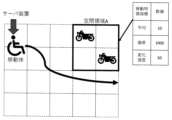
- Example 2 In a second embodiment, a case will be described in which this system avoids a contact accident between a moving body 3 (automatic senior car) and a parked motorcycle.
- the 4 cells surrounded by the thick frame on the upper right are dynamic objects where motorcycles are parked.
- the space area A it is assumed that real-time image sensor data in the virtual real space is transmitted to the moving body 3 moving in the virtual real space.
- the temporal average of the number of point groups (moving feature index) of the image sensor data in the spatial region A is small, "10". Normally, it is determined that this is a spatial region related to a static object and not a parking lot. A determines that the mobile object 3 (motorcycle) is parked infrequently. Therefore, the server device 2 can set a high priority for the image sensor data of the spatial area A, and can preferentially transmit the real-time image sensor data of the spatial area A to the mobile object 3. It is possible to avoid contact accidents between 3 and the parked motorcycle.
- Example 3 In the third embodiment, a case will be described in which the mobile body 3 (a mobile robot that cleans and patrols the facility) moves while avoiding people and obstacles using this system.
- a spatial region where pedestrians jump out, a spatial region where cars jump out, a spatial region where parked vehicles suddenly start, a parked motorcycle overturns, a spatial region where many people are crowded, and a high-speed vehicle is frequent.
- the average, deviation, and tendency of change speed of the number of point groups (moving feature index) of the image sensor data in each spatial region are displayed.
- the priority of the image sensor data is set based on the tendency of the number of (moving feature index). For this reason, the server device 2 preferentially transmits real-time image sensor data of the spatial region with a high priority to the moving body 3 (robot) according to the priority of the image sensor data of each spatial region. This allows the moving body 3 (robot) to clean and patrol while avoiding people and obstacles.
- the server device 2 when the server device 2 learns the movement feature of the image sensor data in the spatial area, the size of the occupancy rate of the spatial area and the presence or absence of periodicity of the movement feature index of the image sensor data in the spatial area are determined. elements may be considered. Further, when the server device 2 learns movement features of image sensor data in the spatial domain, it may perform anomaly prediction by unsupervised machine learning or anomaly prediction by supervised machine learning.
Landscapes
- Engineering & Computer Science (AREA)
- Physics & Mathematics (AREA)
- General Physics & Mathematics (AREA)
- Radar, Positioning & Navigation (AREA)
- Remote Sensing (AREA)
- Computing Systems (AREA)
- Theoretical Computer Science (AREA)
- Electromagnetism (AREA)
- Computer Networks & Wireless Communication (AREA)
- Computer Vision & Pattern Recognition (AREA)
- Accounting & Taxation (AREA)
- Operations Research (AREA)
- Business, Economics & Management (AREA)
- Multimedia (AREA)
- Development Economics (AREA)
- Economics (AREA)
- General Business, Economics & Management (AREA)
- Aviation & Aerospace Engineering (AREA)
- Automation & Control Theory (AREA)
- Image Analysis (AREA)
Abstract
Description
本システムは、図1に示すように、複数の端末装置1と、各端末装置1と所定の通信路を介して接続されたサーバ装置2とを備え、各端末装置1で取得された実空間におけるイメージセンサデータをサーバ装置2で制御し、実空間の各空間領域におけるリアルタイムのイメージセンサデータを移動体3(例えば、自動運転車等)にネットワーク等を介して送信するものとなされている。
前記端末装置1は、道路の信号機、街頭、防犯カメラ装置や交通カメラ装置などに設置され、図1に示すように、実空間における点群からなるイメージセンサデータを取得するセンサ部11と、センサ部11により取得された実空間における点群からなるイメージセンサデータをサーバ装置2に送信する端末側送信部12とを備える。
前記サーバ装置2は、端末装置1側の近い場所に配置され、図2に示すように、各端末装置1から送信されてきた実空間における点群からなるイメージセンサデータを受信する受信部21と、実空間における点群からなるイメージセンサデータを集約する集約部22と、実空間における各空間領域のイメージセンサデータの移動特徴指標を学習する学習部23と、実空間における各空間領域のイメージセンサデータの移動特徴指標に関する情報を記憶する移動特徴指標情報記憶部24と、実空間における各空間領域のイメージセンサデータの優先度を制御する制御部25と、実空間における優先度の高い空間領域のイメージセンサデータを移動体3に送信するサーバ側送信部26とを備える。なお、本実施形態では、実空間における各空間領域のイメージセンサデータの点群の個数を移動特徴指標として説明する。
まず、本システムにより実空間における各空間領域のイメージセンサデータの移動特徴指標に関して学習する時の流れについて、図9を参照しつつ説明する。なお、以下の説明において、「ステップ」を「S」と略記することとする。
次に、本システムより実空間における各空間領域のイメージセンサデータの所定の移動体に送信するときの流れについて、図10を参照しつつ説明する。
実施例1では、本システムによって移動体3(自動運転車)の出会い頭の事故を回避する場合について説明する。
実施例2では、本システムによって移動体3(自動運転シニアカー)と駐車バイクの接触事故を回避する場合について説明する。
実施例3では、本システムによって移動体3(施設内を掃除やパトロールを行う移動ロボット)が人や障害物を回避しながら移動する場合について説明する。
11…センサ部
12…端末側送信部
2…サーバ装置
21…受信部
22…集約部
23…学習部
24…移動特徴指標情報記憶部
25…制御部
26…サーバ側送信部
3…移動体
Claims (13)
- 一ないし複数の端末装置とサーバ装置が通信可能な状態で接続され、各端末装置で取得されたイメージセンサデータをサーバ装置で制御するイメージセンサデータ制御システムであって、
前記端末装置は、
実空間における点群からなるイメージセンサデータを取得するセンサ部と、
前記センサ部により取得された実空間における点群からなるイメージセンサデータを前記サーバ装置に送信する端末側送信部とを備え、
前記サーバ装置は、
前記各端末装置から送信されてきた実空間における点群からなるイメージセンサデータを受信する受信部と、
前記受信部により受信された実空間における点群からなるイメージセンサデータを集約する集約部と、
前記集約部により集約された実空間における点群からなるイメージセンサデータに基づいて、実空間における各空間領域の静的物体または動的物体の移動に関する特徴を示すものとして、実空間における各空間領域のイメージセンサデータの移動特徴指標を学習する学習部と、
前記学習部により学習された実空間における各空間領域のイメージセンサデータの移動特徴指標に関する情報を記憶する移動特徴指標情報記憶部と、
前記移動特徴指標情報記憶部に記憶されている実空間における各空間領域のイメージセンサデータの移動特徴指標に関する情報に基づいて、実空間における各空間領域のイメージセンサデータの優先度を設定する制御部とを備えることを特徴とするイメージセンサデータ制御システム。 - 前記端末装置は、同一の実空間に対して異なる方向から点群からなるイメージセンサデータを取得するように複数設けられ、
前記集約部は、各端末装置で取得された点群からなるイメージセンサデータを時系列的に合成することにより集約する請求項1に記載のイメージセンサデータ制御システム。 - 前記学習部は、実空間における各空間領域のイメージセンサデータの点群の個数を移動特徴指標とする請求項1に記載のイメージセンサデータ制御システム。
- 前記学習部は、実空間における各空間領域のイメージセンサデータの移動特徴指標の時間的変化を学習することにより、静的物体または動的物体に係る空間領域を判断する請求項1に記載のイメージセンサデータ制御システム。
- 前記学習部は、実空間における所定の空間領域のイメージセンサデータの移動特徴指標の偏差が所定の範囲内である場合、静的物体に係る空間領域であると判断する一方、該所定の空間領域のイメージセンサデータの移動特徴指標の偏差が所定の範囲外にある場合、動的物体に係る空間領域であると判断する請求項4に記載のイメージセンサデータ制御システム。
- 前記学習部は、実空間における所定の空間領域のイメージセンサデータの移動特徴指標の平均が所定の閾値を超える場合、当該空間領域において移動する動的物体が多いと判断する一方、イメージセンサデータの移動特徴指標の平均が所定の閾値以下の場合、当該空間領域において移動する動的物体が少ないと判断する請求項4に記載のイメージセンサデータ制御システム。
- 前記制御部は、前記学習部により動的物体であると判断された空間領域のイメージセンサデータの優先度を高く設定する一方、前記学習部により静的物体であると判断された空間領域のイメージセンサデータの優先度を低く設定する請求項4または請求項5に記載のイメージセンサデータ制御システム。
- 前記制御部は、前記学習部により移動する動的物体が多いと判断された空間領域のイメージセンサデータの優先度を高く設定する一方、前記学習部により移動する動的物体が少ないと判断された空間領域のイメージセンサデータの優先度を低く設定する請求項6に記載のイメージセンサデータ制御システム。
- 前記制御部は、端末装置においてリアルタイムに取得されたイメージセンサデータについて、実空間における所定の空間領域のイメージセンサデータの移動特徴指標の所定時間内の変化速度が所定の閾値を超える場合、当該空間領域における動的物体の移動速度が速いと判断して、当該空間領域のイメージセンサデータの優先度を高く設定する一方、実空間における所定の空間領域のメージセンサデータの移動特徴指標の所定時間内の変化速度が所定の閾値以下の場合、当該空間領域における動的物体の移動速度が遅いと判断して、当該空間領域のイメージセンサデータの優先度を低く設定する請求項1に記載のイメージセンサデータ制御システム。
- 前記集約部の出力側にサーバ側送信部が設けられ、
前記制御部は、前記端末装置においてリアルタイムに取得されたイメージセンサデータについて、優先度が高く設定された空間領域のイメージセンサデータを所定の移動体に優先的に送信するように前記サーバ側送信部を制御する請求項1に記載のイメージセンサデータ制御システム。 - 前記制御部は、前記端末装置においてリアルタイムに取得されたイメージセンサデータについて、優先度が高く設定された空間領域のイメージセンサデータを前記サーバ装置に優先的に送信するように前記端末側送信部を制御する請求項1に記載のイメージセンサデータ制御システム。
- 前記端末側送信部は、前記サーバ装置から各空間領域のイメージセンサデータの優先度をあらかじめ受信し、優先度が高く設定された空間領域のイメージセンサデータを前記サーバ装置に優先的に送信する請求項1に記載のイメージセンサデータ制御システム。
- [規則26に基づく補充 24.10.2022]
前記実空間は、空間領域として格子状に並んだ複数のセルから構成され、
前記制御部は、各セルごとにイメージセンサデータの優先度を設定する請求項1に記載のイメージセンサデータ制御システム。
Priority Applications (2)
| Application Number | Priority Date | Filing Date | Title |
|---|---|---|---|
| EP22880903.4A EP4418015A1 (en) | 2021-10-15 | 2022-10-06 | Image sensor data control system |
| JP2023554465A JPWO2023063208A1 (ja) | 2021-10-15 | 2022-10-06 |
Applications Claiming Priority (2)
| Application Number | Priority Date | Filing Date | Title |
|---|---|---|---|
| JP2021-169461 | 2021-10-15 | ||
| JP2021169461 | 2021-10-15 |
Publications (1)
| Publication Number | Publication Date |
|---|---|
| WO2023063208A1 true WO2023063208A1 (ja) | 2023-04-20 |
Family
ID=85987460
Family Applications (1)
| Application Number | Title | Priority Date | Filing Date |
|---|---|---|---|
| PCT/JP2022/037427 WO2023063208A1 (ja) | 2021-10-15 | 2022-10-06 | イメージセンサデータ制御システム |
Country Status (3)
| Country | Link |
|---|---|
| EP (1) | EP4418015A1 (ja) |
| JP (1) | JPWO2023063208A1 (ja) |
| WO (1) | WO2023063208A1 (ja) |
Cited By (1)
| Publication number | Priority date | Publication date | Assignee | Title |
|---|---|---|---|---|
| US12065495B2 (en) | 2018-04-06 | 2024-08-20 | Atyr Pharma, Inc. | Compositions and methods comprising anti-NRP2 antibodies |
Citations (6)
| Publication number | Priority date | Publication date | Assignee | Title |
|---|---|---|---|---|
| JP2011118591A (ja) * | 2009-12-02 | 2011-06-16 | Murata Machinery Ltd | 自律移動装置 |
| US20190311546A1 (en) * | 2018-04-09 | 2019-10-10 | drive.ai Inc. | Method for rendering 2d and 3d data within a 3d virtual environment |
| WO2020195965A1 (ja) * | 2019-03-28 | 2020-10-01 | ソニー株式会社 | 情報処理装置、情報処理方法及びプログラム |
| CN111965627A (zh) * | 2020-08-18 | 2020-11-20 | 湖北亿咖通科技有限公司 | 一种车辆的多激光雷达标定方法 |
| JP2021043475A (ja) * | 2017-12-25 | 2021-03-18 | 住友電気工業株式会社 | 送信装置、点群データ収集システムおよびコンピュータプログラム |
| CN112986982A (zh) * | 2021-05-12 | 2021-06-18 | 长沙万为机器人有限公司 | 环境地图参照定位方法、装置和移动机器人 |
-
2022
- 2022-10-06 JP JP2023554465A patent/JPWO2023063208A1/ja active Pending
- 2022-10-06 WO PCT/JP2022/037427 patent/WO2023063208A1/ja active Application Filing
- 2022-10-06 EP EP22880903.4A patent/EP4418015A1/en active Pending
Patent Citations (6)
| Publication number | Priority date | Publication date | Assignee | Title |
|---|---|---|---|---|
| JP2011118591A (ja) * | 2009-12-02 | 2011-06-16 | Murata Machinery Ltd | 自律移動装置 |
| JP2021043475A (ja) * | 2017-12-25 | 2021-03-18 | 住友電気工業株式会社 | 送信装置、点群データ収集システムおよびコンピュータプログラム |
| US20190311546A1 (en) * | 2018-04-09 | 2019-10-10 | drive.ai Inc. | Method for rendering 2d and 3d data within a 3d virtual environment |
| WO2020195965A1 (ja) * | 2019-03-28 | 2020-10-01 | ソニー株式会社 | 情報処理装置、情報処理方法及びプログラム |
| CN111965627A (zh) * | 2020-08-18 | 2020-11-20 | 湖北亿咖通科技有限公司 | 一种车辆的多激光雷达标定方法 |
| CN112986982A (zh) * | 2021-05-12 | 2021-06-18 | 长沙万为机器人有限公司 | 环境地图参照定位方法、装置和移动机器人 |
Non-Patent Citations (1)
| Title |
|---|
| SHACKLETON, J.VANVOORST, B.HESCH, J.: "Tracking people with a 360-degree lidar", IEEE INTERNATIONAL CONFERENCE ON ADVANCED VIDEO AND SIGNAL BASED SURVEILLANCE, August 2010 (2010-08-01), pages 420 - 426, XP031772055 |
Cited By (1)
| Publication number | Priority date | Publication date | Assignee | Title |
|---|---|---|---|---|
| US12065495B2 (en) | 2018-04-06 | 2024-08-20 | Atyr Pharma, Inc. | Compositions and methods comprising anti-NRP2 antibodies |
Also Published As
| Publication number | Publication date |
|---|---|
| EP4418015A1 (en) | 2024-08-21 |
| JPWO2023063208A1 (ja) | 2023-04-20 |
Similar Documents
| Publication | Publication Date | Title |
|---|---|---|
| US10229590B2 (en) | System and method for improved obstable awareness in using a V2X communications system | |
| US10349011B2 (en) | System and method for improved obstacle awareness in using a V2X communications system | |
| US10613547B2 (en) | System and method for improved obstacle awareness in using a V2X communications system | |
| US10460180B2 (en) | Systems and methods for visual classification with region proposals | |
| US11915593B2 (en) | Systems and methods for machine learning based collision avoidance | |
| US20200133288A1 (en) | Sensor fusion by operations-control vehicle for commanding and controlling autonomous vehicles | |
| CN109884656B (zh) | 用于实现扫描视场分区的激光雷达及测距方法 | |
| CN109307869B (zh) | 用于增加激光雷达探测器的视场的设备和照明装置 | |
| JP2020534518A (ja) | 低レイテンシ動作計画更新を有するインテリジェントladarシステム | |
| US11635763B2 (en) | 3D occlusion reasoning for accident avoidance | |
| US10605924B2 (en) | Method and apparatus cross segment detection in a lidar system | |
| CN107745383B (zh) | 一种机器人控制方法和机器人 | |
| US10591923B2 (en) | Method and apparatus for parallel illumination by a VCSEL array | |
| US20190086513A1 (en) | Method and apparatus for frame rate boosting in lidar array | |
| WO2023063208A1 (ja) | イメージセンサデータ制御システム | |
| US20190041865A1 (en) | Method and Apparatus for Parallel Acquisition in Lidar Array | |
| CN110789515B (zh) | 机动车辆中用于硬件验证的系统和方法 | |
| WO2021011665A1 (en) | Intelligent beam forming for a range detection device of a vehicle | |
| EP4197714A1 (en) | Utilizing light detection and ranging sensors for vehicle-to-everything communications | |
| US20230192142A1 (en) | Autonomous vehicle data offload to download pole by free space optical link | |
| CN115825982A (zh) | 一种下雨环境下无人机点云数据扫描实现方法和系统 | |
| CN111103596A (zh) | 激光雷达系统及其控制方法 | |
| CN115240470A (zh) | 基于nr-v2x的弱势交通参与者碰撞预警系统与方法 | |
| CN114489136A (zh) | 一种无人智能体集群编队控制方法 | |
| Hexmoor et al. | Economized sensor data processing with vehicle platooning |
Legal Events
| Date | Code | Title | Description |
|---|---|---|---|
| 121 | Ep: the epo has been informed by wipo that ep was designated in this application |
Ref document number: 22880903 Country of ref document: EP Kind code of ref document: A1 |
|
| ENP | Entry into the national phase |
Ref document number: 2023554465 Country of ref document: JP Kind code of ref document: A |
|
| WWE | Wipo information: entry into national phase |
Ref document number: 18700906 Country of ref document: US |
|
| WWE | Wipo information: entry into national phase |
Ref document number: 202427035841 Country of ref document: IN |
|
| WWE | Wipo information: entry into national phase |
Ref document number: 2022880903 Country of ref document: EP |
|
| NENP | Non-entry into the national phase |
Ref country code: DE |
|
| ENP | Entry into the national phase |
Ref document number: 2022880903 Country of ref document: EP Effective date: 20240515 |