WO2023063191A1 - Method and device for controlling the fuel injection of an internal combustion engine - Google Patents
Method and device for controlling the fuel injection of an internal combustion engine Download PDFInfo
- Publication number
- WO2023063191A1 WO2023063191A1 PCT/JP2022/037304 JP2022037304W WO2023063191A1 WO 2023063191 A1 WO2023063191 A1 WO 2023063191A1 JP 2022037304 W JP2022037304 W JP 2022037304W WO 2023063191 A1 WO2023063191 A1 WO 2023063191A1
- Authority
- WO
- WIPO (PCT)
- Prior art keywords
- injection
- fuel
- penetration length
- spray penetration
- calculated
- Prior art date
- Legal status (The legal status is an assumption and is not a legal conclusion. Google has not performed a legal analysis and makes no representation as to the accuracy of the status listed.)
- Ceased
Links
Images


Classifications
-
- F—MECHANICAL ENGINEERING; LIGHTING; HEATING; WEAPONS; BLASTING
- F02—COMBUSTION ENGINES; HOT-GAS OR COMBUSTION-PRODUCT ENGINE PLANTS
- F02D—CONTROLLING COMBUSTION ENGINES
- F02D41/00—Electrical control of supply of combustible mixture or its constituents
- F02D41/30—Controlling fuel injection
- F02D41/38—Controlling fuel injection of the high pressure type
- F02D41/40—Controlling fuel injection of the high pressure type with means for controlling injection timing or duration
- F02D41/402—Multiple injections
-
- F—MECHANICAL ENGINEERING; LIGHTING; HEATING; WEAPONS; BLASTING
- F02—COMBUSTION ENGINES; HOT-GAS OR COMBUSTION-PRODUCT ENGINE PLANTS
- F02D—CONTROLLING COMBUSTION ENGINES
- F02D37/00—Non-electrical conjoint control of two or more functions of engines, not otherwise provided for
- F02D37/02—Non-electrical conjoint control of two or more functions of engines, not otherwise provided for one of the functions being ignition
-
- F—MECHANICAL ENGINEERING; LIGHTING; HEATING; WEAPONS; BLASTING
- F02—COMBUSTION ENGINES; HOT-GAS OR COMBUSTION-PRODUCT ENGINE PLANTS
- F02D—CONTROLLING COMBUSTION ENGINES
- F02D41/00—Electrical control of supply of combustible mixture or its constituents
- F02D41/02—Circuit arrangements for generating control signals
- F02D41/04—Introducing corrections for particular operating conditions
- F02D41/047—Taking into account fuel evaporation or wall wetting
-
- F—MECHANICAL ENGINEERING; LIGHTING; HEATING; WEAPONS; BLASTING
- F02—COMBUSTION ENGINES; HOT-GAS OR COMBUSTION-PRODUCT ENGINE PLANTS
- F02D—CONTROLLING COMBUSTION ENGINES
- F02D41/00—Electrical control of supply of combustible mixture or its constituents
- F02D41/02—Circuit arrangements for generating control signals
- F02D41/04—Introducing corrections for particular operating conditions
- F02D41/06—Introducing corrections for particular operating conditions for engine starting or warming up
- F02D41/062—Introducing corrections for particular operating conditions for engine starting or warming up for starting
- F02D41/064—Introducing corrections for particular operating conditions for engine starting or warming up for starting at cold start
-
- F—MECHANICAL ENGINEERING; LIGHTING; HEATING; WEAPONS; BLASTING
- F02—COMBUSTION ENGINES; HOT-GAS OR COMBUSTION-PRODUCT ENGINE PLANTS
- F02D—CONTROLLING COMBUSTION ENGINES
- F02D2200/00—Input parameters for engine control
- F02D2200/02—Input parameters for engine control the parameters being related to the engine
- F02D2200/06—Fuel or fuel supply system parameters
- F02D2200/0602—Fuel pressure
-
- F—MECHANICAL ENGINEERING; LIGHTING; HEATING; WEAPONS; BLASTING
- F02—COMBUSTION ENGINES; HOT-GAS OR COMBUSTION-PRODUCT ENGINE PLANTS
- F02D—CONTROLLING COMBUSTION ENGINES
- F02D2200/00—Input parameters for engine control
- F02D2200/02—Input parameters for engine control the parameters being related to the engine
- F02D2200/06—Fuel or fuel supply system parameters
- F02D2200/0606—Fuel temperature
-
- F—MECHANICAL ENGINEERING; LIGHTING; HEATING; WEAPONS; BLASTING
- F02—COMBUSTION ENGINES; HOT-GAS OR COMBUSTION-PRODUCT ENGINE PLANTS
- F02D—CONTROLLING COMBUSTION ENGINES
- F02D2200/00—Input parameters for engine control
- F02D2200/02—Input parameters for engine control the parameters being related to the engine
- F02D2200/06—Fuel or fuel supply system parameters
- F02D2200/0614—Actual fuel mass or fuel injection amount
-
- F—MECHANICAL ENGINEERING; LIGHTING; HEATING; WEAPONS; BLASTING
- F02—COMBUSTION ENGINES; HOT-GAS OR COMBUSTION-PRODUCT ENGINE PLANTS
- F02D—CONTROLLING COMBUSTION ENGINES
- F02D2700/00—Mechanical control of speed or power of a single cylinder piston engine
- F02D2700/10—Control of the timing of the fuel supply period with relation to the piston movement
-
- F—MECHANICAL ENGINEERING; LIGHTING; HEATING; WEAPONS; BLASTING
- F02—COMBUSTION ENGINES; HOT-GAS OR COMBUSTION-PRODUCT ENGINE PLANTS
- F02D—CONTROLLING COMBUSTION ENGINES
- F02D35/00—Controlling engines, dependent on conditions exterior or interior to engines, not otherwise provided for
- F02D35/02—Controlling engines, dependent on conditions exterior or interior to engines, not otherwise provided for on interior conditions
-
- F—MECHANICAL ENGINEERING; LIGHTING; HEATING; WEAPONS; BLASTING
- F02—COMBUSTION ENGINES; HOT-GAS OR COMBUSTION-PRODUCT ENGINE PLANTS
- F02M—SUPPLYING COMBUSTION ENGINES IN GENERAL WITH COMBUSTIBLE MIXTURES OR CONSTITUENTS THEREOF
- F02M51/00—Fuel-injection apparatus characterised by being operated electrically
- F02M51/06—Injectors peculiar thereto with means directly operating the valve needle
- F02M51/061—Injectors peculiar thereto with means directly operating the valve needle using electromagnetic operating means
- F02M51/0625—Injectors peculiar thereto with means directly operating the valve needle using electromagnetic operating means characterised by arrangement of mobile armatures
- F02M51/0635—Injectors peculiar thereto with means directly operating the valve needle using electromagnetic operating means characterised by arrangement of mobile armatures having a plate-shaped or undulated armature not entering the winding
- F02M51/0642—Injectors peculiar thereto with means directly operating the valve needle using electromagnetic operating means characterised by arrangement of mobile armatures having a plate-shaped or undulated armature not entering the winding the armature having a valve attached thereto
- F02M51/0653—Injectors peculiar thereto with means directly operating the valve needle using electromagnetic operating means characterised by arrangement of mobile armatures having a plate-shaped or undulated armature not entering the winding the armature having a valve attached thereto the valve being an elongated body, e.g. a needle valve
-
- Y—GENERAL TAGGING OF NEW TECHNOLOGICAL DEVELOPMENTS; GENERAL TAGGING OF CROSS-SECTIONAL TECHNOLOGIES SPANNING OVER SEVERAL SECTIONS OF THE IPC; TECHNICAL SUBJECTS COVERED BY FORMER USPC CROSS-REFERENCE ART COLLECTIONS [XRACs] AND DIGESTS
- Y02—TECHNOLOGIES OR APPLICATIONS FOR MITIGATION OR ADAPTATION AGAINST CLIMATE CHANGE
- Y02T—CLIMATE CHANGE MITIGATION TECHNOLOGIES RELATED TO TRANSPORTATION
- Y02T10/00—Road transport of goods or passengers
- Y02T10/10—Internal combustion engine [ICE] based vehicles
- Y02T10/40—Engine management systems
Definitions
- the present subject-matter relates to a method and a control device for controlling a fuel injection of an internal combustion engine, preferably a spark ignited combustion engine, by means of an injection profile comprising multiple fuel injections, which is generated depending on a calculated spray penetration length of the fuel to be injected.
- Patent Literature 1 US 7770813 B2
- Patent Literature 1 describes a method for reducing the spray penetration using multiple injections and providing a dwell time between the successive injection events that allows each successive injection event to be independent of other successive events so that the overall spray penetration of the total injection event is reduced relative to that of a single fluid injection event.
- Patent Literature 1 does neither provide automatic generation of the injection profile nor does it take into account different combustion modes that require the injection timing to be aligned with the ignition timing.
- An object of the described subject matter is to provide a model-based generation of an injection profile that considers the requirements of different combustion modes in various operation points of an internal combustion engine.
- the claimed subject matter comprises a method for controlling a fuel injection of an internal combustion engine (hereinafter also shortly “engine”).
- the engine may be a spark ignited engine.
- the engine may be a spark ignited engine having a direct fuel injection.
- the internal combustion engine comprises at least one cylinder, in which a combustion chamber is formed by a cylinder wall, a cylinder head and a top of a piston.
- the piston moves reciprocally in the cylinder driven by a crankshaft.
- the piston may be connected to the crankshaft via a connecting rod.
- the piston may move by the piston stroke s from a bottom dead center (BTC) to a top dead center (TDC).
- BTC bottom dead center
- TDC top dead center
- the crank angle-dependent piston stroke s can be determined with the following formula, wherein j denotes the crank angle, rdenotes the stroke length of the crank shaft and l s denotes the rod ratio:
- the engine further comprises at least one fuel injector which is configured to inject fuel into the combustion chamber.
- the at least one fuel injector may be a high-pressure injector configured to inject fuel directly in the combustion chamber.
- the high-pressure injector may be driven by a solenoid valve or a piezo element.
- the engine comprises at least one control device which is configured to control the fuel injection.
- the control device may be the engine control unit (ECU).
- the control device may be integrated into the internal combustion engine or, alternatively, it may be disposed at a position within the vehicle remote to the combustion engine, and the control device and the engine may be connected via one or more signal lines.
- the control device may be the engine control device (ECU) or one or more separate control devices.
- the fuel injection is controlled by comparing a calculated spray penetration length of fuel to be injected into the combustion chamber with a spray penetration length threshold at predetermined time points of an injection cycle.
- the spray penetration length of the fuel to be injected has to be shorter than the distance between the spray hole and the cylinder wall und the distance between the spray hole and the piston.
- the distance of the spray jets from the cylinder wall is taken into account when selecting an injector for a particular engine by performing a so-called spray targeting, which illustrates the location of the spray jets in the combustion chamber.
- spray targeting which illustrates the location of the spray jets in the combustion chamber.
- the spray penetration length of the fuel to be injected may depend on several parameters. The most important parameters may be the fuel pressure and the pressure and temperature in the combustion chamber. These parameters may be considered in the physical model for calculating the spray penetration length described below.
- the first predetermined time point for performing the comparison is an end of the injection cycle.
- injection cycle shall be understood as the area(s) of the engine working cycle in which injection should take place to generate torque and to fulfill the requirements of the predetermined combustion mode.
- a complete injection cycle which may be independent of the combustion mode, may start shortly after closing of the exhaust valves and end just before ignition timing.
- the injection cycle may vary, e.g., in homogenous combustion mode, the injection cycle may end before the end of the intake stroke, to achieve a homogenous cylinder charge. This means that in homogenous combustion mode the end of the injection cycle may be, e.g., before Bottom Dead Center.
- the last injection event may end, e.g., close before ignition timing. Starting the calculation at the end of the injection cycle considers the conditions of the different combustion modes, which require an alignment of the latest injection with the ignition.
- a fuel injection profile comprising multiple fuel injections is generated. This is done by setting an injection signal to a positive value at the predetermined time points of the injection cycle in which the calculated spray penetration length is smaller than or equal to the spray penetration length threshold, and resetting the injection signal to zero at the predetermined time points of the injection cycle in which the calculated spray penetration length exceeds the spray penetration length threshold.
- the injection timing and duration of multiple injections may be generated by allowing an injection only if the spray penetration length is below or equal to the spray penetration length threshold which represents the maximum allowable spray penetration length.
- an injection signal By setting an injection signal to an arbitrary positive value, e.g., to one, if a spray penetration length is allowable and resetting the injection signal to zero, if a spray penetration length is not allowable, a signal to be output by the control device to the injector representing the fuel injection profile can be generated. In case the time between setting and resetting the injection signal is smaller than the minimum actuation time of the injector, the injection signal is set to zero in this range.
- the generation of the fuel injection profile is carried out until a fuel amount calculated on the basis of the previously generated fuel injection profile exceeds a predetermined fuel amount.
- the predetermined fuel amount may be the total amount of fuel needed to meet the torque and/or lambda control requirements. After finishing the generation of the fuel injection profile, it is sent to the injector for performing the injection.
- the claimed method automatically calculates the complete injection profile, i.e., the number of injections and the start and end time of each injection for the subsequent injection cycle.
- the calculation is executed in a backward manner starting from the end of an injection cycle and finalizing the calculation at the beginning of an injection event. This allows for adapting the multiple injections to different combustion modes so that emissions and fuel consumption can be optimized at the same time.
- the spray penetration length threshold may be determined depending on a position of the piston and a predetermined combustion mode.
- the claimed method assumes an injector adapted to the combustion chamber, so that only the distance between the spray hole and the top of the piston has to be considered when determine the spray penetration length threshold.
- a geometric threshold value for the penetration length of the spray jet can be determined using the following formula:
- Predetermined combustion modes may be, e.g., a lean-burn combustion with a stratified cylinder charge, a lean-burn combustion with a mixture of homogenous and stratified cylinder charge and a homogenous combustion with a stoichiometric cylinder charge.
- stratified charge operation is to deliver a mixture that is sufficiently rich for combustion in the vicinity of the spark plug, while the rest of the cylinder receives a very lean mixture.
- Stratified charge operation enables reduced fuel consumption when running at lower loads due to reduced pumping losses and overall lean combustion.
- several injections are carried out during the compression stroke, with the last injection taking place just before ignition. This means that the spray penetration length threshold may be set to zero, e.g., during the intake stroke and during the first half of the compression stroke, to include the requirements of the combustion mode into the generation of the fuel injection profile.
- the spray penetration length threshold may be set to zero, e.g., during the first half of the compression stroke.
- the spray penetration length threshold may be set to zero, e.g., during the compression stroke.
- the spray penetration length of fuel to be injected may be calculated using a physical model, which considers all relevant influences, such as the fuel pressure and the pressure and temperature in the combustion chamber.
- the model is represented by the following formula, in which k denotes a calibration parameter depending on pressure p cyl , temperature T cyl and gas concentration x cyl in the combustion chamber, Dpdenotes the difference between the fuel pressure and the cylinder pressure, tdenotes the time after start of injection and a, b denote weighting coefficients of the pressure difference Dp and the time t:
- a start of an injection may be determined by a backward calculation at a time when the calculated spray penetration length exceeds the spray penetration length threshold.
- the period/distance between the start of the injection and the time, where the spray has achieved the spray penetration length threshold may be identified by using a map, which may be previously calibrated via test data from injector spray experiments.
- a time period of the fuel injection profile between a falling edge by resetting the injection signal to zero and a subsequent rising edge by setting the injection signal to the positive value may be longer than a predetermined time threshold.
- the distance between the end of one injection and the start of a subsequent injection may be longer than a predetermined time threshold.
- the predetermined time threshold may be the dwell time of the injector or, if necessary, an additional offset may be added to the dwell time to further increase or decrease the distance between two injection events.
- the end of the injection cycle may be determined depending on the predetermined combustion mode in relation to an ignition timing of the internal combustion engine.
- the duration of an injection cycle within the meaning of the claimed subject matter may depend on the combustion mode.
- the end of the injection cycle may be further determined in relation to an ignition timing. This means that if the ignition timing shifts, the complete injection profile will automatically be shifted as well, to maintain a constant distance between the end of the last injection and the ignition.
- the fuel injection profile is generated by a backward calculation beginning at the end of the injection cycle.
- a rising edge determined as the first may characterize an end of a last injection
- a falling edge determined as the last may characterize a start of a first injection.
- a first setting of the injection signal (a first rising edge) may represent the end of a last injection
- a last falling edge of the injection signal may represent the start of the first injection.
- the last falling edge of the injection signal may be determined depending on the predetermined fuel amount as explained below.
- the fuel amount/total quantity of fuel calculated on the basis of the previously generated fuel injection profile is determined each time the injection signal is reset.
- a fuel amount/quantity of fuel of an injection corresponding to a time period between a last falling edge and a previous rising edge of the fuel injection profile may be calculated using a physical hydraulic model.
- the fuel amount of the last injection whose injection duration is defined by the time between the last falling edge and the previous rising edge may be calculated.
- the calculated fuel amount may be added to a sum of previously calculated fuel amounts until the sum of previously calculated fuel amounts exceeds the predetermined fuel amount.
- a physics-based model is used to calculate the mass flow rate (MFR) of each injection event.
- MFR mass flow rate
- C d denotes the flow coefficient of the injector
- A denotes the opening section of the injector
- r f denotes the fuel density
- Dpde denotes the difference between the fuel pressure and the cylinder pressure.
- the start of the first injection may be determined based on a difference between the fuel amount calculated on the basis of the previously generated fuel injection profile and the predetermined fuel amount.
- the claimed method ensures that the total quantity of fuel (sum of all single injection events) satisfies a predetermined fuel amount required, e.g., from lambda or torque control. Therefore, the method checks the total quantity of fuel after each calculation step and stops the calculation in case the the predetermined fuel amount is achieved. In this way, only the earliest injection event is used for the adjustment/control of the predetermined fuel amount. This is beneficial because the earliest injection event has the largest distance from spark event and therefore does not cause a disturbance on the ignition behaviour.
- the predetermined time points of the injection cycle at which the fuel injection profile is determined are arranged at equidistant intervals with respect to a crankshaft angle of the internal combustion engine.
- the equidistant intervals may be, e.g., 1°CA, 0.5°CA, 0.1°CA depending on computational resources and required calculation accuracy.
- the method is executed on a crank angle resolved calculation basis, which means that it is independent of the engine speed.
- the claimed subject matter further includes a control device for an internal combustion engine, which is configured to perform the above-described method or aspects thereof, and an internal combustion engine, which comprises the control device.
- a control device for an internal combustion engine which is configured to perform the above-described method or aspects thereof
- an internal combustion engine which comprises the control device.
- to comprise the control device means that the control device may be integrated into the internal combustion engine or, alternatively, it may be disposed at a position within the vehicle remote to the combustion engine, and the control device and the engine may be connected via one or more signal lines.
- the claimed subject matter includes a computer program product storable in a memory comprising instructions which, when carried out by a computer or a computing unit, cause the computer to perform the above- described method or aspects thereof, as well as a computer-readable [storage] medium comprising instructions which, when executed by a computer, cause the computer to carry out said method or aspects thereof.
- the claimed subject-matter allows to reduce the emissions of an internal combustion engine and, at the same time, its calibration effort by performing multiple injection on the basis of a model-based automatically generated fuel injection profile. Furthermore, the requirements of different combustion modes for multiple injection are taken into account when generating the fuel injection profile.
- FIG. 1 depicts schematically an example of a single cylinder spark ignited combustion engine
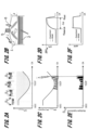
- FIG. 2A Figure 2A depict schematically a generation of an injection profile according to the claimed method
- Figure 2B depict schematically a generation of an injection profile according to the claimed method
- Figure 2C Figure 2C depict schematically a generation of an injection profile according to the claimed method
- Figure 2D depict schematically a generation of an injection profile according to the claimed method
- Figure 2E Figure 2E depict schematically a generation of an injection profile according to the claimed method
- FIG. 1 depicts schematically an example of a single cylinder spark ignited combustion engine
- FIG. 2B Figure 2B depict schematically a generation of an injection profile according to the claimed method
- Figure 2C depict schematically a generation of an injection profile according to the claimed method
- Figure 2D depict schematically a generation of an injection profile according to the claimed method
- Figure 2E depict schematically a generation of an injection profile according to the claimed method
- Figure 2F depict schematically a generation of an injection profile according to the claimed method;
- Figures 3 depicts a flowchart describing exemplary the method steps of the claimed method;
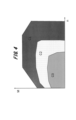
- Figures 4 depicts an example of an engine map;
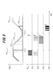
- Figures 5 depicts exemplary different spray length penetration thresholds depending on the respective combustion mode according to the claimed method;
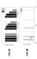
- Figure 6A Figure 6A depict an example of achieved emission reduction using different injection profiles according to the claimed method.
- Figure 6B Figure 6B depict an example of achieved emission reduction using different injection profiles according to the claimed method.
- FIG. 1 an example of a spark ignited single cylinder combustion engine is schematically illustrated, to explain the background of the claimed subject matter. It is clear to those skilled in the art that the claimed subject matter is not limited to a single cylinder engine, but can be applied to engines with any number of cylinders.
- the depicted single cylinder engine comprises a combustion chamber 1 which is formed by the cylinder wall 1a, the top of the piston 2 and a cylinder head (not depicted) in which the intake valve 3, the outlet valve 4, the fuel injector 5 and the spark plug 6 are arranged.
- the piston 2 may move in the cylinder by the piston stroke s from a bottom dead center BTC to a top dead center TDC.
- the fuel injector 5 and the spark plug 6 are electrically connected to the control device 7.
- the control device 7 may determine the fuel injection profile according to the claimed method and send it to the injector 5. Furthermore, the control device 7 may control the ignition timing of the spark plug 6.
- the control device 7 may be integrated into the internal combustion engine or, alternatively, it may be disposed at a position within a vehicle remote to the combustion engine, and the control device 7 and the engine may be connected via one or more signal lines.
- the control device 7 may be the engine control device (ECU) or one or more separate control devices.
- Fig. 1 the piston is positioned at BDC. However, it can be derived from Fig, 1 that if the piston is positioned close to TDC, which is the case when the injection takes place near the ignition timing, only a small fuel penetration length is allowable in order to avoid piston wetting.
- Fig. 2A The phenomenon of wall and piston wetting is schematically depicted in Fig. 2A in connection with the resulting spray penetration length threshold SPL thres,0 .
- the spray may initially impinge on the outside of the piston, and as the piston continues to approach top dead center, the impingement point may move toward the piston center.
- the described impingement of the fuel on the piston surface defines the geometric spray penetration length threshold SPL thres,0 expressed by Formula (2).
- the parameters of Formula (2) are depicted in Fig.
- the maximum allowable spray penetration length SPL thres,0 depends on the angle a between a center axis of a spray jet 7 and the center axis of the cylinder and the distance d between the spray hole of the injector and the top of the piston, which is dependent on the piston stroke s.
- Fig. 2C shows an example of the comparison between the stepwise calculated spray penetration length SPL with the geometric spray calculation length threshold SPL thres,0 which leads to the spray penetration lengths of the multiple injections.
- the depicted example refers to a combustion mode with catalyst heating, in which the ignition timing takes places after the firing top dead center TDC F .
- the calculation of the spray penetration length SPL starts at ignition timing to determine the fuel injection profile of the late multiple injections needed to accelerate the catalyst heating.
- Fig. 2D shows that the spray penetration length SPLcalculated by the model according to Formula (3) matches very well with experimental results, wherein the unbroken line indicates the model data and the broken line indicates the experimental data. Further, based on Figure 2D, it can be shown as to how to determine the start of an injection via a backward calculation. First, the distance ⁇ between the start of the hydraulic injection ⁇ start,k and the current position ⁇ act , where the spray has achieved a certain spray length SPL k , is identified.
- the position ⁇ act is indicated by a vertikal broken line in Figure 2D which intersects the x-axis at the position where the SPL curve has reached the value SPL k .
- the start of the hydraulic injection ⁇ start,k is also indicated by a broken vertical line which crosses the x-axis at the position where the SPL curve starts to rise.
- the difference between the two positions is the distance ⁇ .
- Fig. 2E schematically shows the timing and quantity of the late multiple injections resulting from the calculation of the allowable spray penetration length shown in Fig. 2C.
- a fuel injection profile is depicted that comprises six injections in the region around TDC in order to improve the catalyst heating.
- the fuel injection profile may be generated by setting the injection signal S inj to a positive value at the predetermined time points of the injection cycle in which the calculated spray penetration length is smaller than or equal to the spray penetration length threshold, and resetting the injection signal to zero at the predetermined time points of the injection cycle in which the calculated spray penetration length exceeds the spray penetration length threshold.
- the mass fuel rate MFRcalculated according to Formula (4) also agrees very well with experimental results.
- Fig. 3 shows a flow chart that describes the process steps of the claimed method by way of example.
- the spray penetration threshold SPL thres may be determined according to Formula (2). Additionally, the combustion mode may be taken into account, as described below in combination with Fig. 5.
- the injection counter k is set to zero so that the crank angle j at which the calculation may start is set to the latest possible crank angle j latest , namely to the crank angle being the end of the injection cycle (S102).
- the crank angle for determining the next injection may be set to a crank angle j whose distance from the current crank angle j act corresponds to the dwell time of the injector.
- the injection signal S inj is set to 1 (S106) and the method precedes via step S106 to the next crank for calculating the spray penetration length there.
- the spray penetration length calculation is terminated for the current injection and the injection signal S inj is set to 0 (S108). Subsequently the start of the current injection event is determined based on the calculated spray penetration length SPL k .
- a model is used to return the distance ⁇ between the start of the hydraulic injection ⁇ start,k and the current position ⁇ act where the spray has achieved a certain spray length SPL k , which is preferably a predefined value or the like.
- the model that is used can be a map-based structure which is calibrated via test data from injector spray experiments.
- the calculated fuel amount Q model,k is higher than the minimum fuel amount Q min of the injector, the calculated fuel amount Q model,k is added to the previously calculated fuel amounts, and it is checked whether the sum of the calculated fuel amounts is equal to or higher than the predetermined fuel amount Q total .
- step S111 the method precedes to step S111 for calculating the next injection. Otherwise, the generation of the fuel injection profile is terminated.
- the claimed method exemplarily described in Fig. 3 enables the automatic generation of a complete fuel injection profile that can be injected in the subsequent injection cycle.
- the method performs a backward calculation and takes into account the requirements of the various combustion modes as well as the constraints imposed by the injector.
- Fig. 4 the distribution of different combustion modes over the entire engine map is shown.
- the stratified combustion mode C3 with an overall air-fuel ratio of l > 1 may be performed to reduce fuel consumption.
- the so-called homogeneous-stratified combustion mode C2 can be carried out to extend the advantages of a lean mixture to higher loads and speeds.
- the homogenous combustion mode C1 may be needed to achieve the required engine power.
- Fig. 5 depicts an example of the required fuel injection profiles corresponding to the respective combustion modes C1 to C3 and the resulting spray penetration length threshold SPL.
- Each fuel injection profile may be generated by setting the injection signal S inj to a positive value, e.g., to one, at time points of the injection cycle in which the calculated spray penetration length is smaller than or equal to the spray penetration length threshold, and resetting the injection signal to zero time points of the injection cycle in which the calculated spray penetration length exceeds the spray penetration length threshold.
- catalyst heating mode C4 may be carried out after cold start of the engine, which must then be additionally taken into account when generating the fuel injection profile.
- the depicted example three injections during the intake stroke are performed when operating the engine in homogenous mode.
- the latest injection ends at BDC so that the spray penetration length threshold SPL thres, C1 can be set to zero after BDC.
- the depicted example shows two injections during the intake stroke and three injections during the compression stroke for the homogenous-stratified mode C2.
- the latest injection ends just before ignition timing, e.g., close before ignition timing, which means that the spray penetration length threshold SPL thres, C2 can only be set to zero in the first half of the compression stroke.
- the stratified combustion mode C3 four injections are performed during the compression stroke, resulting in a spray penetration length threshold SPL thres, C3 which can be set to zero during the intake stroke and at the beginning of the compression stroke.
- the catalyst heating mode one or more injections are carried out after TDC just before the late ignition timing, e.g., close before ignition timing. This means that a separate fuel injection profile may be generated for catalyst heating which may be combined with one of the other fuel injection modes depending on the combustion mode selected.
- Figs. 6A, 6B depict an example of achieved emission reduction using different injection profiles according to the claimed method.
- the specific effective fuel consumption be, the nitrogen oxides NOx, the hydrocarbons HC and the particle number for multiple injections comprising three and five injections are depicted compared to the values measured when using a single injection.
- Fig. 6B shows the timing and duration of the various injections, represented by the injection current.
- the single injection is carried out during the intake stroke and the three multiple injections are also performed during the intake stroke.
- the five very short multiple injections are distributed between the intake and compression strokes, with three injections performed during the intake stroke and two injections performed during the compression stroke. The last of the five injections is carried out shortly before the ignition timing.
- generating a fuel injection profile according to the claimed method helps to reduce the emissions without effecting the fuel consumption.
- the hydrocarbons HC and the particle number can be significantly reduced when performing multiple injection according to the claimed subject matter. While the nitrogen oxides NOx are almost the same for three and five injections, respectively, the hydrocarbons HC and the particle number PN can be further reduced for five injections according to the injection profile shown in Fig. 6B.
- the claimed subject-matter allows to reduce the emissions of an internal combustion engine and, at the same time, its calibration effort by performing multiple injection on the basis of a model-based automatically generated fuel injection profile. Furthermore, the requirements of current combustion processes for multiple injection are taken into account when generating the fuel injection profile, which helps to significantly reduce the calculation effort.
- the present disclosure may be embodied as a method, an apparatus (including a device, machine, system, computer program product, and/or any other apparatus), or a combination of the foregoing.
- embodiments of the present disclosure may take the form of an entirely hardware embodiment, an entirely software embodiment (including firmware, resident software, micro-code, etc.), or an embodiment combining software and hardware aspects that may generally be referred to herein as a "system".
- embodiments of the present disclosure may take the form of a computer program product on a computer-readable medium having computer-executable program code embodied in the medium.
- arrows may be used in drawings to represent communication, transfer, or other activity involving two or more entities. Double-ended arrows generally indicate that activity may occur in both directions (e.g., a command/request in one direction with a corresponding reply back in the other direction, or peer-to-peer communications initiated by either entity), although in some situations, activity may not necessarily occur in both directions.
- Single-ended arrows generally may indicate activity exclusively or predominantly in one direction, although it should be noted that, in certain situations, such directional activity actually may involve activities in both directions (e.g., a message from a sender to a receiver and an acknowledgement back from the receiver to the sender, or establishment of a connection prior to a transfer and termination of the connection following the transfer).
- directional activity actually may involve activities in both directions (e.g., a message from a sender to a receiver and an acknowledgement back from the receiver to the sender, or establishment of a connection prior to a transfer and termination of the connection following the transfer).
- the type of arrow used in a particular drawing to represent a particular activity is exemplary and should not be seen as limiting.
- the computer-executable program code may be provided to a processor of a general purpose computer, special purpose computer, or other programmable data processing apparatus to produce a particular machine, such that the program code, which executes via the processor of the computer or other programmable data processing apparatus, create means for implementing the functions/acts/outputs specified in the flowchart, block diagram block or blocks, figures, and/or written description.
- These computer-executable program code may also be stored in a computer-readable memory that can direct a computer or other programmable data processing apparatus to function in a particular manner, such that the program code stored in the computer readable memory produce an article of manufacture including instruction means which implement the function/act/output specified in the flowchart, block diagram block(s), figures, and/or written description.
- the computer-executable program code may also be loaded onto a computer or other programmable data processing apparatus to cause a series of operational steps to be performed on the computer or other programmable apparatus to produce a computer-implemented process such that the program code which executes on the computer or other programmable apparatus provides steps for implementing the functions/acts/outputs specified in the flowchart, block diagram block(s), figures, and/or written description.
- computer program implemented steps or acts may be combined with operator or human implemented steps or acts in order to carry out an embodiment.
- a device may include, without limitation, a bridge, router, bridge-router (brouter), switch, node, server, computer, appliance, or other type of device.
- Such devices typically include one or more network interfaces for communicating over a communication network and a processor (e.g., a microprocessor with memory and other peripherals and/or application-specific hardware) configured accordingly to perform device functions.
- Communication networks generally may include public and/or private networks; may include local-area, wide-area, metropolitan-area, storage, and/or other types of networks; and may employ communication technologies including, but in no way limited to, analog technologies, digital technologies, optical technologies, wireless technologies (e.g., Bluetooth), networking technologies, and internetworking technologies.
- communication technologies including, but in no way limited to, analog technologies, digital technologies, optical technologies, wireless technologies (e.g., Bluetooth), networking technologies, and internetworking technologies.
- devices may use communication protocols and messages (e.g., messages created, transmitted, received, stored, and/or processed by the device), and such messages may be conveyed by a communication network or medium.
- communication protocols and messages e.g., messages created, transmitted, received, stored, and/or processed by the device
- a communication message generally may include, without limitation, a frame, packet, datagram, user datagram, cell, or other type of communication message.
- references to specific communication protocols are exemplary, and it should be understood that alternative embodiments may, as appropriate, employ variations of such communication protocols (e.g., modifications or extensions of the protocol that may be made from time-to-time) or other protocols either known or developed in the future.
- logic flows may be described herein to demonstrate various aspects and should not be construed to limit the disclosure to any particular logic flow or logic implementation.
- the described logic may be partitioned into different logic blocks (e.g., programs, modules, functions, or subroutines) without changing the overall results.
- logic elements may be added, modified, omitted, performed in a different order, or implemented using different logic constructs (e.g., logic gates, looping primitives, conditional logic, and other logic constructs) without changing the overall results.
- logic constructs e.g., logic gates, looping primitives, conditional logic, and other logic constructs
- the present disclosure may be embodied in many different forms, including, but in no way limited to, computer program logic for use with a processor (e.g., a microprocessor, microcontroller, digital signal processor, or general purpose computer), programmable logic for use with a programmable logic device (e.g., a Field Programmable Gate Array (FPGA) or other PLD), discrete components, integrated circuitry (e.g., an Application Specific Integrated Circuit (ASIC)), or any other means including any combination thereof
- Computer program logic implementing some or all of the described functionality is typically implemented as a set of computer program instructions that is converted into a computer executable form, stored as such in a computer readable medium, and executed by a microprocessor under the control of an operating system.
- Hardware-based logic implementing some or all of the described functionality may be implemented using one or more appropriately configured FPGAs.
- Computer program logic implementing all or part of the functionality previously described herein may be embodied in various forms, including, but in no way limited to, a source code form, a computer executable form, and various intermediate forms (e.g., forms generated by an assembler, compiler, linker, or locator).
- Source code may include a series of computer program instructions implemented in any of various programming languages (e.g., an object code, an assembly language, or a high-level language such as Fortran, C, C++, JAVA, or HTML) for use with various operating systems or operating environments.
- the source code may define and use various data structures and communication messages.
- the source code may be in a computer executable form (e.g., via an interpreter), or the source code maybe converted (e.g., via a translator, assembler, or compiler) into a computer executable form.
- Computer-executable program code for carrying out operations of embodiments of the present disclosure may be written in an object oriented, scripted or unscripted programming language such as Java, Perl, Smalltalk, C++, or the like.
- the computer program code for carrying out operations of embodiments may also be written in conventional procedural programming languages, such as the "C" programming language or similar programming languages.
- Computer program logic implementing all or part of the functionality previously described herein may be executed at different times on a single processor (e.g., concurrently) or may be executed at the same or different times on multiple processors and may run under a single operating system process/thread or under different operating system processes/threads.
- computer process may refer generally to the execution of a set of computer program instructions regardless of whether different computer processes are executed on the same or different processors and regardless of whether different computer processes run under the same operating system process/thread or different operating system processes/threads.
- the computer program may be fixed in any form (e.g., source code form, computer executable form, or an intermediate form) either permanently or transitorily in a tangible storage medium, such as a semiconductor memory device (e.g., a RAM, ROM, PROM, EEPROM, or Flash-Programmable RAM), a magnetic memory device (e.g., a diskette or fixed disk), an optical memory device (e.g., a CD-ROM), a PC card (e.g., PCMCIA card), or other memory device.
- a semiconductor memory device e.g., a RAM, ROM, PROM, EEPROM, or Flash-Programmable RAM
- a magnetic memory device e.g., a diskette or fixed disk
- an optical memory device e.g., a CD-ROM
- PC card e.g., PCMCIA card
- the computer program may be fixed in any form in a signal that is transmittable to a computer using any of various communication technologies, including, but in no way limited to, analog technologies, digital technologies, optical technologies, wireless technologies (e.g., Bluetooth), networking technologies, and internetworking technologies.
- various communication technologies including, but in no way limited to, analog technologies, digital technologies, optical technologies, wireless technologies (e.g., Bluetooth), networking technologies, and internetworking technologies.
- the computer program may be distributed in any form as a removable storage medium with accompanying printed or electronic documentation (e.g., shrink wrapped software), preloaded with a computer system (e.g., on system ROM or fixed disk), or distributed from a server or electronic bulletin board over the communication system (e.g., the Internet or World Wide Web).
- a computer system e.g., on system ROM or fixed disk
- a server or electronic bulletin board over the communication system (e.g., the Internet or World Wide Web).
- Hardware logic including programmable logic for use with a programmable logic device
- implementing all or part of the functionality previously described herein may be designed using traditional manual methods, or may be designed, captured, simulated, or documented electronically using various tools, such as Computer Aided Design (CAD), a hardware description language (e.g., VHDL or AHDL), or a PLD programming language (e.g., PALASM, ABEL, or CUPL).
- CAD Computer Aided Design
- a hardware description language e.g., VHDL or AHDL
- PLD programming language e.g., PALASM, ABEL, or CUPL
- the computer readable medium may be, for example but not limited to, an electronic, magnetic, optical, electromagnetic, infrared, or semiconductor system, apparatus, device, or medium.
- the computer readable medium include, but are not limited to, an electrical connection having one or more wires or other tangible storage medium such as a portable computer diskette, a hard disk, a random access memory (RAM), a read-only memory (ROM), an erasable programmable read-only memory (EPROM or Flash memory), a compact disc read-only memory (CD-ROM), or other optical or magnetic storage device.
- a portable computer diskette a hard disk
- RAM random access memory
- ROM read-only memory
- EPROM or Flash memory erasable programmable read-only memory
- CD-ROM compact disc read-only memory
- Programmable logic may be fixed either permanently or transitorily in a tangible storage medium, such as a semiconductor memory device (e.g., a RAM, ROM, PROM, EEPROM, or Flash-Programmable RAM), a magnetic memory device (e.g., a diskette or fixed disk), an optical memory device (e.g., a CD-ROM), or other memory device.
- a semiconductor memory device e.g., a RAM, ROM, PROM, EEPROM, or Flash-Programmable RAM
- a magnetic memory device e.g., a diskette or fixed disk
- an optical memory device e.g., a CD-ROM
- the programmable logic may be fixed in a signal that is transmittable to a computer using any of various communication technologies, including, but in no way limited to, analog technologies, digital technologies, optical technologies, wireless technologies (e.g., Bluetooth), networking technologies, and internetworking technologies.
- various communication technologies including, but in no way limited to, analog technologies, digital technologies, optical technologies, wireless technologies (e.g., Bluetooth), networking technologies, and internetworking technologies.
- the programmable logic may be distributed as a removable storage medium with accompanying printed or electronic documentation (e.g., shrink wrapped software), preloaded with a computer system (e.g., on system ROM or fixed disk), or distributed from a server or electronic bulletin board over the communication system (e.g., the Internet or World Wide Web).
- a computer system e.g., on system ROM or fixed disk
- a server or electronic bulletin board over the communication system
- some aspects may be implemented as a combination of both software (e.g., a computer program product) and hardware. Still other embodiments of the may be implemented as entirely hardware, or entirely software.
Landscapes
- Engineering & Computer Science (AREA)
- Chemical & Material Sciences (AREA)
- Combustion & Propulsion (AREA)
- Mechanical Engineering (AREA)
- General Engineering & Computer Science (AREA)
- Electrical Control Of Air Or Fuel Supplied To Internal-Combustion Engine (AREA)
- Fuel-Injection Apparatus (AREA)
Abstract
Description
An object of the described subject matter is to provide a model-based generation of an injection profile that considers the requirements of different combustion modes in various operation points of an internal combustion engine.

According to the claimed subject matter, the fuel injection is controlled by
comparing a calculated spray penetration length of fuel to be injected into the combustion chamber with a spray penetration length threshold at predetermined time points of an injection cycle.
As explained above, the claimed method assumes an injector adapted to the combustion chamber, so that only the distance between the spray hole and the top of the piston has to be considered when determine the spray penetration length threshold. A geometric threshold value for the penetration length of the spray jet can be determined using the following formula:

Predetermined combustion modes may be, e.g., a lean-burn combustion with a stratified cylinder charge, a lean-burn combustion with a mixture of homogenous and stratified cylinder charge and a homogenous combustion with a stoichiometric cylinder charge.
For homogenous combustion, no injection during the compression stroke is needed, so that the spray penetration length threshold may be set to zero, e.g., during the compression stroke.


The equidistant intervals may be, e.g., 1°CA, 0.5°CA, 0.1°CA depending on computational resources and required calculation accuracy. In other words, the method is executed on a crank angle resolved calculation basis, which means that it is independent of the engine speed.
[Fig. 1] Figure 1 depicts schematically an example of a single cylinder spark ignited combustion engine;
[Fig. 2A] Figure 2A depict schematically a generation of an injection profile according to the claimed method;
[Fig. 2B] Figure 2B depict schematically a generation of an injection profile according to the claimed method;
[Fig. 2C] Figure 2C depict schematically a generation of an injection profile according to the claimed method;
[Fig. 2D] Figure 2D depict schematically a generation of an injection profile according to the claimed method;
[Fig. 2E] Figure 2E depict schematically a generation of an injection profile according to the claimed method;
[Fig. 2F] Figure 2F depict schematically a generation of an injection profile according to the claimed method;
[Fig. 3] Figures 3 depicts a flowchart describing exemplary the method steps of the claimed method;
[Fig. 4] Figures 4 depicts an example of an engine map;
[Fig. 5] Figures 5 depicts exemplary different spray length penetration thresholds depending on the respective combustion mode according to the claimed method;
[Fig. 6A] Figure 6A depict an example of achieved emission reduction using different injection profiles according to the claimed method.
[Fig. 6B] Figure 6B depict an example of achieved emission reduction using different injection profiles according to the claimed method.
2 Piston
3 Intake valve
4 Exhaust valve
5 Injector
6 Spark plug
7 Spray jet
Claims (13)
- Method for controlling a fuel injection of an internal combustion engine, the internal combustion engine comprising
at least one cylinder, in which a combustion chamber is formed by a cylinder wall, a cylinder heat and a top of a piston, the piston moving reciprocally in the cylinder driven by a crankshaft, at least one fuel injector configured to inject fuel into the combustion chamber, and at least one control device configured to control the fuel injection, wherein
the fuel injection is controlled by
comparing a calculated spray penetration length of fuel to be injected into the combustion chamber with a spray penetration length threshold at predetermined time points of an injection cycle, the first predetermined time point being an end of the injection cycle,
generating a fuel injection profile comprising multiple fuel injections by setting an injection signal to a positive value at the predetermined time points of the injection cycle in which the calculated spray penetration length is smaller than or equal to the spray penetration length threshold, and resetting the injection signal to zero at the predetermined time points of the injection cycle in which the calculated spray penetration length exceeds the spray penetration length threshold until a fuel amount calculated on the basis of the previously generated fuel injection profile exceeds a predetermined fuel amount, and
sending the generated fuel injection profile to the injector for performing the injection. - The method according to claim 1, wherein the spray penetration length threshold is determined depending on a position of the piston and a predetermined combustion mode.
- The method according to claim 1, wherein the spray penetration length of fuel to be injected is calculated using a physical model, which considers the fuel pressure, the fuel temperature and the conditions in the combustion chamber.
- The method according to claim 1, wherein a start of an injection is determined by a backward calculation at a time when the calculated spray penetration length exceeds the spray penetration length threshold.
- The method according to claim 1, wherein a time period of the fuel injection profile between a falling edge by resetting the injection signal to zero and a subsequent rising edge by setting the injection signal to the positive value is longer than a predetermined time threshold.
- The method according to claim 1, wherein the end of the injection cycle is determined depending on the predetermined combustion mode in relation to an ignition timing of the internal combustion engine.
- The method according to claim 1, wherein
the fuel injection profile is generated by a backward calculation beginning at the end of the injection cycle, wherein a rising edge determined as the first characterizes an end of a last injection, and a falling edge determined as the last characterizes a start of a first injection. - The method according to claim 1, wherein
the fuel amount calculated on the basis of the previously generated fuel injection profile is determined each time the injection signal is reset by calculating a fuel amount of an injection corresponding to a time period between a last falling edge and a previous rising edge of the fuel injection profile using a physical hydraulic model, and adding the calculated fuel amount to a sum of previously calculated fuel amounts until the sum of previously calculated fuel amounts exceeds the predetermined fuel amount. - The method according to claim 7, wherein
the start of the first injection is determined based on a difference between the fuel amount calculated on the basis of the previously generated fuel injection profile and the predetermined fuel amount. - The method according to claim 1, wherein the predetermined time points of the injection cycle at which the fuel injection profile is determined are arranged at equidistant intervals with respect to a crankshaft angle of the internal combustion engine.
- Control device for an internal combustion engine, the internal combustion engine comprising
at least one cylinder, in which a combustion chamber is formed by a cylinder wall and a top of a piston, the piston moving reciprocally in the cylinder driven by a crankshaft, at least one fuel injector configured to inject fuel into the combustion chamber, wherein
the control device is configured to perform the method according to claim 1. - Internal combustion engine comprising
at least one cylinder, in which a combustion chamber is formed by a cylinder wall and a top of a piston, the piston moving reciprocally in the cylinder driven by a crankshaft,
at least one fuel injector configured to inject fuel into the combustion chamber, and the control device of claim 11. - A computer program product storable in a memory comprising instructions which, when carried out by a computer, cause the computer to perform the method according to claim 1.
Priority Applications (3)
| Application Number | Priority Date | Filing Date | Title |
|---|---|---|---|
| CN202280065281.1A CN118019904A (en) | 2021-10-15 | 2022-10-05 | Method and device for controlling fuel injection of an internal combustion engine |
| JP2024518508A JP7719960B2 (en) | 2021-10-15 | 2022-10-05 | Method for controlling fuel injection in an internal combustion engine, control device, internal combustion engine and computer program product |
| DE112022003501.3T DE112022003501T5 (en) | 2021-10-15 | 2022-10-05 | METHOD AND DEVICE FOR CONTROLLING THE FUEL INJECTION OF AN INTERNAL COMBUSTION ENGINE |
Applications Claiming Priority (2)
| Application Number | Priority Date | Filing Date | Title |
|---|---|---|---|
| DE102021211658.2A DE102021211658A1 (en) | 2021-10-15 | 2021-10-15 | METHOD AND DEVICE FOR CONTROLLING THE FUEL INJECTION OF AN INTERNAL ENGINE |
| DE102021211658.2 | 2021-10-15 |
Publications (1)
| Publication Number | Publication Date |
|---|---|
| WO2023063191A1 true WO2023063191A1 (en) | 2023-04-20 |
Family
ID=85773121
Family Applications (1)
| Application Number | Title | Priority Date | Filing Date |
|---|---|---|---|
| PCT/JP2022/037304 Ceased WO2023063191A1 (en) | 2021-10-15 | 2022-10-05 | Method and device for controlling the fuel injection of an internal combustion engine |
Country Status (4)
| Country | Link |
|---|---|
| JP (1) | JP7719960B2 (en) |
| CN (1) | CN118019904A (en) |
| DE (2) | DE102021211658A1 (en) |
| WO (1) | WO2023063191A1 (en) |
Citations (2)
| Publication number | Priority date | Publication date | Assignee | Title |
|---|---|---|---|---|
| JP2009133278A (en) * | 2007-11-30 | 2009-06-18 | Toyota Motor Corp | Internal combustion engine |
| US20110155097A1 (en) * | 2009-12-25 | 2011-06-30 | Hitachi Automotive Systems, Ltd. | Control Apparatus for Direct Injection Type Internal Combustion Engine |
Family Cites Families (8)
| Publication number | Priority date | Publication date | Assignee | Title |
|---|---|---|---|---|
| JP3692930B2 (en) * | 2000-11-27 | 2005-09-07 | 日産自動車株式会社 | Combustion control device for direct-injection spark-ignition internal combustion engine |
| DE10105755A1 (en) * | 2001-02-08 | 2002-08-29 | Bosch Gmbh Robert | Method, computer program and control and / or regulating device for operating an internal combustion engine and internal combustion engine |
| FR2827913B1 (en) | 2001-07-27 | 2003-09-19 | Inst Francais Du Petrole | METHOD FOR CONTROLLING THE INJECTION OF A FUEL FOR A DIRECT INJECTION INTERNAL COMBUSTION ENGINE |
| US7210448B2 (en) * | 2002-06-11 | 2007-05-01 | Cummins, Inc. | Internal combustion engine producing low emissions |
| DE10329506A1 (en) | 2003-06-30 | 2005-01-20 | Daimlerchrysler Ag | Auto-ignition internal combustion engine |
| US7770813B2 (en) | 2006-10-11 | 2010-08-10 | Gm Global Technology Operations, Inc. | Spray penetration control method |
| DE102010033005A1 (en) * | 2010-07-31 | 2012-02-02 | Daimler Ag | Internal combustion engine and associated operating method |
| DE102014110635B4 (en) | 2014-07-28 | 2020-12-10 | Denso Corporation | Process for the detection and prevention of lubrication deficiencies on the piston running surface |
-
2021
- 2021-10-15 DE DE102021211658.2A patent/DE102021211658A1/en not_active Withdrawn
-
2022
- 2022-10-05 DE DE112022003501.3T patent/DE112022003501T5/en active Pending
- 2022-10-05 WO PCT/JP2022/037304 patent/WO2023063191A1/en not_active Ceased
- 2022-10-05 CN CN202280065281.1A patent/CN118019904A/en active Pending
- 2022-10-05 JP JP2024518508A patent/JP7719960B2/en active Active
Patent Citations (2)
| Publication number | Priority date | Publication date | Assignee | Title |
|---|---|---|---|---|
| JP2009133278A (en) * | 2007-11-30 | 2009-06-18 | Toyota Motor Corp | Internal combustion engine |
| US20110155097A1 (en) * | 2009-12-25 | 2011-06-30 | Hitachi Automotive Systems, Ltd. | Control Apparatus for Direct Injection Type Internal Combustion Engine |
Also Published As
| Publication number | Publication date |
|---|---|
| JP7719960B2 (en) | 2025-08-06 |
| JP2024536831A (en) | 2024-10-08 |
| DE102021211658A1 (en) | 2023-04-20 |
| CN118019904A (en) | 2024-05-10 |
| DE112022003501T5 (en) | 2024-05-02 |
Similar Documents
| Publication | Publication Date | Title |
|---|---|---|
| KR100394847B1 (en) | Fuel injection timing control system for direct injection type internal combustion engine and method for the same | |
| US8050846B2 (en) | Apparatus and method for controlling engine | |
| CN102235257A (en) | Method of multiple injection timing control | |
| RU2656867C1 (en) | Internal combustion engine control device and method of controlling internal combustion engine | |
| US9803568B2 (en) | Control system of internal combustion engine (as amended) | |
| US7628013B2 (en) | Control device of charge compression ignition-type internal combustion engine | |
| JP2018091267A (en) | Control device for internal combustion engine | |
| JP4881927B2 (en) | Fuel injection control device for internal combustion engine | |
| CN106414972A (en) | Control apparatus for internal combustion engine | |
| JP2002276404A (en) | Compression ignition type internal combustion engine | |
| US8718903B2 (en) | Direct injection spark ignition internal combustion engine, and fuel injection control method therefor | |
| US20160273475A1 (en) | Control system for spark-ignition internal combustion engine | |
| CN113006960B (en) | Control method and device of engine | |
| JP7719960B2 (en) | Method for controlling fuel injection in an internal combustion engine, control device, internal combustion engine and computer program product | |
| JP2002256924A (en) | Combustion control device for compression ignition type engine | |
| JP2009174450A (en) | Fuel injection control device for internal combustion engine | |
| JP2021050641A (en) | Fuel injection control device | |
| US7043349B2 (en) | Method and system for inferring exhaust temperature of a variable compression ratio engine | |
| JP2002322928A (en) | Combustion control device for compression ignition type engine | |
| JP2007040219A (en) | Control device for internal combustion engine | |
| JP4583626B2 (en) | Engine combustion control device | |
| JPH10331682A (en) | Combustion stabilizer for direct injection spark ignition engine | |
| JP2006057562A (en) | Internal combustion engine and operation control device for internal combustion engine | |
| US20170089290A1 (en) | Control apparatus for internal combustion engine | |
| JP3948465B2 (en) | Combustion control device for internal combustion engine |
Legal Events
| Date | Code | Title | Description |
|---|---|---|---|
| 121 | Ep: the epo has been informed by wipo that ep was designated in this application |
Ref document number: 22880887 Country of ref document: EP Kind code of ref document: A1 |
|
| WWE | Wipo information: entry into national phase |
Ref document number: 112022003501 Country of ref document: DE |
|
| ENP | Entry into the national phase |
Ref document number: 2024518508 Country of ref document: JP Kind code of ref document: A |
|
| WWE | Wipo information: entry into national phase |
Ref document number: 202280065281.1 Country of ref document: CN |
|
| 122 | Ep: pct application non-entry in european phase |
Ref document number: 22880887 Country of ref document: EP Kind code of ref document: A1 |