WO2023063071A1 - 容器 - Google Patents
容器 Download PDFInfo
- Publication number
- WO2023063071A1 WO2023063071A1 PCT/JP2022/035868 JP2022035868W WO2023063071A1 WO 2023063071 A1 WO2023063071 A1 WO 2023063071A1 JP 2022035868 W JP2022035868 W JP 2022035868W WO 2023063071 A1 WO2023063071 A1 WO 2023063071A1
- Authority
- WO
- WIPO (PCT)
- Prior art keywords
- container
- inner container
- slide
- outer container
- semi
- Prior art date
- Legal status (The legal status is an assumption and is not a legal conclusion. Google has not performed a legal analysis and makes no representation as to the accuracy of the status listed.)
- Ceased
Links
Images


Classifications
-
- B—PERFORMING OPERATIONS; TRANSPORTING
- B65—CONVEYING; PACKING; STORING; HANDLING THIN OR FILAMENTARY MATERIAL
- B65D—CONTAINERS FOR STORAGE OR TRANSPORT OF ARTICLES OR MATERIALS, e.g. BAGS, BARRELS, BOTTLES, BOXES, CANS, CARTONS, CRATES, DRUMS, JARS, TANKS, HOPPERS, FORWARDING CONTAINERS; ACCESSORIES, CLOSURES, OR FITTINGS THEREFOR; PACKAGING ELEMENTS; PACKAGES
- B65D77/00—Packages formed by enclosing articles or materials in preformed containers, e.g. boxes, cartons, sacks or bags
- B65D77/04—Articles or materials enclosed in two or more containers disposed one within another
-
- B—PERFORMING OPERATIONS; TRANSPORTING
- B65—CONVEYING; PACKING; STORING; HANDLING THIN OR FILAMENTARY MATERIAL
- B65D—CONTAINERS FOR STORAGE OR TRANSPORT OF ARTICLES OR MATERIALS, e.g. BAGS, BARRELS, BOTTLES, BOXES, CANS, CARTONS, CRATES, DRUMS, JARS, TANKS, HOPPERS, FORWARDING CONTAINERS; ACCESSORIES, CLOSURES, OR FITTINGS THEREFOR; PACKAGING ELEMENTS; PACKAGES
- B65D83/00—Containers or packages with special means for dispensing contents
- B65D83/76—Containers or packages with special means for dispensing contents for dispensing fluent contents by means of a piston
-
- Y—GENERAL TAGGING OF NEW TECHNOLOGICAL DEVELOPMENTS; GENERAL TAGGING OF CROSS-SECTIONAL TECHNOLOGIES SPANNING OVER SEVERAL SECTIONS OF THE IPC; TECHNICAL SUBJECTS COVERED BY FORMER USPC CROSS-REFERENCE ART COLLECTIONS [XRACs] AND DIGESTS
- Y02—TECHNOLOGIES OR APPLICATIONS FOR MITIGATION OR ADAPTATION AGAINST CLIMATE CHANGE
- Y02W—CLIMATE CHANGE MITIGATION TECHNOLOGIES RELATED TO WASTEWATER TREATMENT OR WASTE MANAGEMENT
- Y02W30/00—Technologies for solid waste management
- Y02W30/50—Reuse, recycling or recovery technologies
- Y02W30/80—Packaging reuse or recycling, e.g. of multilayer packaging
Definitions
- the present invention relates to containers.
- Patent Document 1 describes a bottomed cylindrical container body in which contents are stored, a top wall portion that closes the upper end opening of the container body, and a container body that is rotatably mounted around the container axis.
- a discharge container including a rotary operating body and a middle plate that is vertically slidably fitted in a container body and moves upward as the rotary operating body rotates. According to this container, since the inner plate can be moved upward by rotating the rotary operation body about the container axis with respect to the container body, the contents accommodated inside the container body are pushed up and the top wall is pushed up. It can be discharged from the discharge port formed in the part.
- Patent Document 1 The discharge container described in Patent Document 1 is disposable after the contents are used, and is not preferable from the viewpoint of reducing the environmental burden and reducing the amount of plastic. Therefore, there is known a container in which only the refill container housed in the outer container is discarded and replaced with a new refill container so that the outer container can be used repeatedly.
- Patent Document 2 describes a substantially cylindrical refill container (inner container) with a bottom for containing contents and a wide-mouthed container (outer container) for detachably containing the refill container.
- a double container is disclosed comprising: In the double container described in Patent Document 2, when the refill container is accommodated in the wide-mouthed container and the engaging means and the engaged means are engaged with each other, each side of the wide-mouthed container is opened. By simply placing a finger on the portion facing the notch and pressing it inward, the two other regions of the peripheral wall of the refill container bend and bulge outward, and the two regions facing each other approach each other. Since the engagement between the wide mouth container and the refill container is easily released, the refill container can be smoothly attached and detached.
- Cited Document 2 requires sufficient force to bend the peripheral wall of the refill container, which is inconvenient.
- a container comprises an inner container capable of accommodating contents therein and having an opening, an outer container having an opening accommodating the inner container in a relatively rotatable manner, and discharging the contents.
- a top surface covering the opening of the inner container, a stage having a female screw and capable of being raised by rotation of the inner container or the outer container, and an outer peripheral surface capable of being screwed with the female screw.
- a cylindrical slide having a male screw and capable of changing its diameter in one direction perpendicular to the central axis of rotation, a bottom surface, a pressing portion erected from the bottom surface, and engaging portions erected from both ends of the bottom surface.
- the inner container has projections on the outer peripheral surface of the lower portion thereof, and the outer container has an elastic portion that engages with the projections, and the push-in member is fitted to the bottom surface of the outer container.
- the slide has an abutting surface that abuts against the pressing portion, and when the pushing member is pushed, the diameter of the slide in the one direction is reduced so that the male screw and the male screw are in contact with each other. The engagement of the female screw is released.
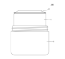
- FIG. 1 is a front view of a container according to a first embodiment;
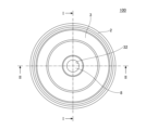
- FIG. 1 is a plan view of a container according to a first embodiment;
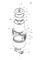
- FIG. 1 is an exploded perspective view of a container according to a first embodiment;
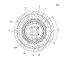
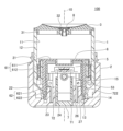
- FIG. FIG. 3 is a sectional view taken along the line II of FIG. 2; 5 is a cross-sectional view taken along line III-III in FIG. 4;
- FIG. 3 is a cross-sectional view taken along the line II-II of FIG. 2;
- FIG. 3 is a cross-sectional view taken along line II of FIG. 2 for explaining the operation of the container when removing the inner container from the outer container;
- FIG. 3 is a cross-sectional view taken along line II of FIG.
- FIG. 3 is a cross-sectional view taken along line II of FIG. 2 for explaining the operation of the container when removing the inner container from the outer container;
- Fig. 3 is a front view of a container according to a second embodiment;
- Fig. 3 is a plan view of a container according to a second embodiment;
- FIG. 10 is a sectional view along IV-IV in FIG. 9;
- Fig. 10 is a front view of a slide according to a second embodiment;
- Fig. 2 is a plan view of a slide according to a second embodiment;
- FIG. 10 is a perspective view of a pushing member according to a second embodiment;
- the same reference numerals may be given to the same constituent elements in each drawing, and redundant description may be omitted.
- the scale of each member in the drawings may differ from the actual scale.
- the direction orthogonal to the central axis of rotation 10 is defined as the radial direction, and in the direction of the axial line along the central axis of rotation 10, the side of the top surface 3 is defined as the upper side, and the side of the bottom surface 23 of the outer container 2 is defined as the lower side.
- FIG. 1 is a front view of the container according to the first embodiment
- FIG. 2 is a plan view of the container according to the first embodiment
- FIG. 3 is an exploded perspective view of the container according to the first embodiment.
- 4 is a sectional view taken along line II in FIG. 2
- FIG. 5 is a sectional view taken along line III-III in FIG. 4
- FIG. 6 is a sectional view taken along line II-II in FIG.
- a container 100 As shown in FIGS. 1 to 6, a container 100 according to the first embodiment of the present invention includes an inner container 1 as a refill (replacement) container, an outer container 2 that accommodates the inner container 1, and an inner container 1.
- a top surface 3 covering an opening 11, a slide 5, a stage 6, and a pushing member 7 are provided.
- the inner container 1 is a cylindrical container with an open top and is capable of containing contents.
- a container that discharges a fluid as the content will be described, but the container that discharges a solid as the content may also be used.
- a fluid may be a liquid, such as a liquid or liquid mixture of pure substances.
- the fluid may be, for example, a solution, a dispersion liquid such as an emulsion, or a suspension, or may be in a state called gel, slurry, paste, cream, or the like.
- the fluid may contain powder or may mainly contain powder.
- the fluid may be a mixture of the above-mentioned fluid and a gas such as nitrogen, rare gas, or air, and contained in the inner container 1 in the form of foam.
- the fluid may be pasty or creamy with a viscosity similar to or higher than that of water.
- Fluids include skin care products such as lotions, milky lotions, face creams, serums, facial cleansers, and cleansing agents, or makeup cosmetics such as basic cosmetics, foundations, makeup bases, concealers, liquid eye shadows, liquid cheeks, and liquid lip products.
- personal care products such as sunscreens, hand soaps, body soaps, hair shampoos, hair dyes, styling agents, hand creams, body creams and body lotions, fragrance products and the like.
- the solids are solid cosmetics or semi-solid cosmetics such as particularly hard hair sticks, hair waxes, lipsticks, and solid beauty essences (for example, those with similar hardness to stick beauty essences). It may be a powder, solid soap, or the like. Foods such as cheese and butter may also be used.
- the material constituting the container 100 is not particularly limited, but resin materials, metal materials, wooden products, and the like can be mentioned.
- resin material for example, polyethylene (PE), polypropylene (PP), polystyrene (PS), polyethylene terephthalate (PET), polyvinyl chloride (PVC), melamine resin, epoxy resin, silicon resin, or the like can be used. . These resins may be used singly or in combination of two or more.
- the inner container 1 has an opening 11 at the top and a side wall 12, and a fitting hole 13 is formed at the bottom.
- a support tube portion 15 is erected in the opposite direction.
- a protrusion 14 that engages with the outer container 2 is provided on the outer peripheral surface of the lower portion (lower end portion) of the inner container 1 .
- the inner peripheral surface of the support cylinder portion 15 is formed with a knurl 151 (protrusion 151) in which a plurality of uneven portions extending in the direction of the rotation center axis 10 are arranged in parallel in the circumferential direction.
- the length of knurling 151 can be any length.
- the stage 6 is inserted inside the support tube portion 15, and the knurls 151 are engaged with the stage 6, so that the support tube portion 15 supports the stage 6 in the circumferential direction so as not to rotate.
- the means for engaging with the stage 6 is not limited to the knurling 151 and may have any configuration.
- the outer container 2 is a cylindrical container with a bottom having an opening 21 at the top, and has a side wall 22 and a bottom surface 23 .
- a fitting hole 24 is formed in the center of the bottom surface 23 , and a first annular wall 26 is erected upward from the fitting hole 24 .
- a second annular wall 27 is erected on the direction outside.
- the pushing member 7 is inserted into the fitting hole 24, and the first annular wall 26 holds the pushing member 7 slidably.
- the shape of the fitting hole 24 in plan view is substantially rectangular, but the shape is not limited to this, and may be any shape in accordance with the shape of the pushing member 7 . As shown in FIG.
- the inner peripheral surface of the second annular wall 27 is formed with a pair of protrusions 28 that engage with the slide 5.
- the protrusions 28 have radially horizontal contact surfaces. .
- the slide 5 is inserted between the first annular wall 26 and the second annular wall 27, and the slide 5 is engaged with the convex portion 28 and the slide 5 (a stepped portion 56, which will be described later), so that the outer container 2 can move the slide 5. It is held so as to be immovable in the vertical direction and movable in the radial direction (horizontal direction on the paper surface of FIG. 4).
- the outer container 2 has a pair of elastic portions 25 on the radially outer side of the second annular wall 27 with the rotation center shaft 10 interposed therebetween.
- the elastic portion 25 has a convex portion 251 at its upper end and is elastically deformable so as to bend radially outward.
- the engagement between the convex portion 251 and the protrusion 14 of the inner container 1 prevents the inner container 1 from accidentally coming off from the outer container 2 unless an upward force is applied to the inner container 1 .
- the inner diameter of the outer container 2 substantially matches the outer diameter of the inner container 1, and the outer container 2 accommodates the inner container 1 in a relatively rotatable manner.
- the upper end of the outer container 2 is positioned below the upper end of the inner container 1 when the inner container 1 is accommodated in the outer container 2, and the upper portion of the peripheral wall 12 of the inner container 1 is exposed from the outer container 2. .
- the user can hold the outer container 2 with one hand and the peripheral wall 12 or the top surface 3 of the inner container 1 with the other hand and relatively rotate the inner container 1 or the outer container 2. .
- the stage 6 can be raised by the rotation of the inner container 1 or the outer container 2, and the upper surface of the stage 6 and the inner surface of the inner container 1 form a container for containing the contents.
- the stage 6 has a circular gate valve 61 having the same outer diameter as the inner diameter of the inner container 1 and a rotor 62 supporting the gate valve 61 and rotating together with the inner container 1 .
- the gate valve 61 and the rotating body 62 may be formed separately or may be integrally formed.
- the gate valve 61 may have a flat portion 611 and a peripheral wall 612 connected from the flat portion 611 and in close contact with the inner peripheral surface of the peripheral wall 12 of the inner container 1 .
- the sluice valve 61 and the inner peripheral surface of the peripheral wall 12 of the inner container 1 are in a state where the sluice valve 61 is stationary with respect to the inner peripheral surface of the peripheral wall 12 and when it moves upward with respect to the inner peripheral surface of the peripheral wall 12 . In this state, the contents contained in the inner container 1 are in liquid-tight contact so as not to leak below the gate valve 61 .
- the rotating body 62 of the stage 6 has a truncated cylindrical shape, and a female screw 622 is formed on the inner peripheral surface of the peripheral wall 621 which is the side surface to engage with the male screw 54 formed on the slide 5 .
- a gap is formed between the peripheral wall 621 of the rotating body 62 and the peripheral wall 612 of the gate valve 61 , and the support cylinder portion 15 of the inner container 1 is inserted into the gap, and the stage 6 is attached to the inner container 1 .
- a plurality of ridges 624 extending in the direction of the rotation center axis 10 are arranged in parallel on the outer peripheral surface of the peripheral wall 621 of the rotating body 62 .
- the stage 6 By engaging the projection 624 with the knurls 151 of the support cylinder portion 15 of the inner container 1 , the stage 6 is attached to the inner container 1 so as to be movable in the direction of the rotation center axis 10 but not rotatable. Thereby, the stage 6 is non-rotatably fixed to the inner container 1 and rotatably fixed to the outer container 2 . In other words, the stage 6 rotates integrally with the inner container 1 . That is, the stage 6 rotates together with the relative rotation of the inner container 1 with respect to the outer container 2, so that the female screw 622 and the male screw 54 of the slide 5 are engaged and interlocked, and the stage 6 rises inside the inner container 1. arranged as possible.
- the means for engaging with the inner container 1 is not limited to the engagement between the plurality of ridges 624 and the knurls 151, but may have any configuration according to the means for engaging with the inner container 1, such as a key and a key groove. . Moreover, when the inner container 1 is removed from the outer container 2 , the stage 6 is removed from the outer container 2 together with the inner container 1 .
- the slide 5 has a cylindrical shape as a whole, has a male screw 54 on its outer peripheral surface that can be screwed with the female screw 622 of the stage 6, and has a diameter in one direction orthogonal to the rotation center axis 10 (Fig. 4 ) can be changed. Specifically, as will be described later, the slide 5 is such that a pair of members divided into two can move away from each other or approach each other in one direction perpendicular to the rotation center axis 10 . As shown in FIG. 3, the male screw 54 is formed not on the entire circumference of the outer peripheral surfaces of the pair of members divided into two parts, but on a symmetrical part of the region with a plane including the rotation center axis 10 as a plane of symmetry. .
- the male screw 54 is formed in an area of an angle A around the rotation center axis 10 in plan view in each of the pair of members.
- Angle A can be, for example, any angle in the range of 5° to 100°, and can be, for example, 70°.
- the slide 5 has a pair of semi-cylindrical members 51 and 52 divided into two along a plane including the rotation center axis 10, and a slide biasing member 53 that is radially expandable.
- the slide biasing member 53 can be, for example, a spring, and can have any configuration as long as it is configured to bias outward in the radial direction.
- a male screw 54 is formed on a part of the outer peripheral surface of each of the semi-cylindrical members 51 and 52 .
- the semi-cylindrical members 51 and 52 are not formed with the male screw 54 at least in the diametrical direction perpendicular to the diameter in one direction.
- the semi-cylindrical members 51 and 52 are arranged on the bottom surface of the outer container 2 so as to be movable in the radial direction and are separated from each other with the slide biasing member 53 held between the semi-cylindrical member 51 and the semi-cylindrical member 52 . It is always biased by a directional biasing force. Thereby, the semi-cylindrical members 51 and 52 can move away from each other or approach each other in one direction orthogonal to the rotation center axis 10 .
- the approximate diameter of the slide 5 in the one direction when it is separated is usually approximately the same as the inner diameter of the stage 6, but when it is close, it is smaller than the inner diameter of the stage 6.
- the male screw 54 of each of the semi-cylindrical members 51 and 52 can be screwed with the female screw 622 of the stage 6 while the semi-cylindrical members 51 and 52 are urged in the direction of separating from each other.
- the male screw 54 of each of the semi-cylindrical members 51 and 52 is separated from the female screw 622 of the stage 6, and the male screw 54 and the female screw 622 are separated from each other. combination is canceled.
- the male screw 54 is separated from the female screw 622, and the male screw 54 and the female screw 622 are disengaged.
- the semi-cylindrical member 51 has a small guide piece 511 protruding in the radial direction, and the end of the small guide piece 511 may be provided with a convex portion 512 .
- the semi-cylindrical member 52 also has a small guide piece 521 projecting in the radial direction, and the end of the small guide piece 521 may be provided with a protrusion 522 .
- the small guide piece 511 of the semi-cylindrical member 51 is inserted into the insertion hole 523 of the semi-cylindrical member 52 , and the small guide piece 521 of the semi-cylindrical member 52 is inserted into the insertion hole 513 of the semi-cylindrical member 51 . Then, the convex portion 512 of the semi-cylindrical member 51 and the convex portion 522 of the semi-cylindrical member 52 are engaged. Thereby, the moving direction and moving distance of the semi-cylindrical members 51 and 52 can be regulated.
- the slide 5 has at least one pair of stepped portions 56 that engage with the convex portions 28 of the outer container 2 at its lower end.
- the stepped portion 56 has a radially horizontal contact surface. Since the stepped portion 56 and the convex portion 28 of the outer container 2 contact and engage with each other on their contact surfaces that are horizontal in the radial direction, the contact surface of the stepped portion 56 is positioned on the contact surface of the convex portion 28 . It is slidable in the radial direction. Thereby, the slide 5 is fixed to the outer container 2 so as to be immovable in the vertical direction and movable in the radial direction.
- the slide 5 has at least a pair of contact surfaces 55 that contact contact surfaces 721 of the pushing member 7, which will be described later.
- the contact surface 55 is an inclined surface whose upper portion is inclined radially outward, in other words, an inclined surface which is inclined in a direction toward the rotation center axis 10 toward the bottom surface 23 side of the outer container 2 .
- a contact surface 55 is formed on each of the semi-cylindrical members 51 and 52 .
- the pushing member 7 is a member that is pushed by the user when removing the inner container 1 from the outer container 2 when replacing the inner container 1 with another inner container 1 .
- the pushing member 7 has a bottom surface 71 , a pressing portion 72 erected from the center of the bottom surface 71 , and locking portions 73 erected from both ends of the bottom surface 71 .
- a contact surface 721 that contacts the contact surface 55 of the slide 5 is formed on the inner peripheral surface of the pressing portion 72.
- the contact surface 721 is an inclined surface whose upper portion is inclined radially outward. 2 is an inclined surface that is inclined in a direction approaching the rotation center axis 10 toward the bottom surface 23 side. As shown in FIG.
- the pressing portion 72 is inserted inside the first annular wall 26 of the outer container 2 and held by the outer container 2 so as to be vertically movable.
- the bottom surface 71 of the pushing member 7 is substantially flush with the bottom surface 23 of the outer container 2 before being pushed (the state in which the container is normally used; hereinafter referred to as the "normal state").
- the slide 5 is attached to the pushing member 7 so that the contact surface 721 of the pressing portion 72 and the contact surface 55 of the slide 5 are in contact with each other.
- the pushing member 7 receives a downward force as a component force of the radially outward force from the slide 5 on the contact surface 721 which is an inclined surface.
- the pushing member 7 Since the pushing member 7 always receives the downward force from the slide 5 , the state where the bottom surface 71 is substantially flush with the bottom surface 23 of the outer container 2 (the lowest operating position of the pushing member 7 ) can be maintained.
- an urging member may be provided at the bottom inside the pressing portion 72 of the pushing member 7 to urge it in the vertical direction.
- the contact surface 721 slides upward along the contact surface 55 of the slide 5 , so that the contact surface 55 of the slide 5 is subjected to a radially inward force (the contact surface 55 of the slide 5 ).
- the pair of semi-cylindrical members 51 and 52 of the slide 5 approach each other in one direction orthogonal to the rotation center axis 10 .
- the locking portion 73 is a member that restricts the elastic portion 25 of the outer container 2 from elastically deforming radially outward.
- the locking portion 73 has an upper member 731 extending from two longitudinal members erected from the bottom surface 71 of the pushing member 7 .
- the upper member 731 has the same thickness as the distance between the elastic portion 25 of the outer container 2 and the inner peripheral surface of the outer container 2, and in a normal state, the elastic portion 25 of the outer container 2 and the outer container 2 is in contact with the inner peripheral surface of As a result, the upper member 731 prevents the elastic portion 25 from elastically deforming radially outward.
- the locking portion 73 has a frame-like configuration having two vertical members and an upper member 731, but is not limited to this, and may have a configuration having a convex portion at the top, for example. . Further, the upward movement of the pushing member 7 is restricted by contacting the lower end of the elastic portion 25 of the outer container 2 . In other words, the position of the lower end of the elastic portion 25 is the operating upper limit of the pushing member 7 .
- At least a pair of projections 722 are provided on the outer peripheral surface of the pressing portion 72, as shown in FIG.
- the protrusion 722 climbs over the first annular wall 26 of the outer container 2 and engages with the upper end of the first annular wall 26 , thereby preventing the pushing member 7 from dropping out of the outer container 2 .
- the top surface 3 is a member that covers the opening 11 of the inner container 1 and has an opening 32 for discharging the contents to the outside.
- the top surface 3 may have an inner peripheral wall 31 for fitting into the inner container 1 , or may be configured to fit into the inner container 1 from the outside.
- the valve body 8 may be arranged in the opening 32 . In this embodiment, the valve body 8 rises as the internal pressure of the contents housed in the inner container 1 increases as the stage 6 rises, and from between the lifted valve body 8 and the top surface 3, Contents are discharged onto the upper surface of the top surface 3 .
- the user can touch only the discharged amount of the contents to be used, so that the user can use the unused amount of the contents without touching it, and the contents can be hygienically stored.
- the valve body 8 may not be provided, and the configuration of the top surface 3 can be made to correspond to the solid substance.
- the container 100 may have a lid (not shown).
- the lid body may be, for example, a screw lid, which is screwed with a male screw formed on the outer peripheral surface of the peripheral wall 22 of the outer container 2 to cover the inner container 1, the top surface 3, and the opening 21 of the outer container 2. It may be fixed so as to cover it.
- the lid body is not limited to a screw lid, and may be, for example, a snap type lid.
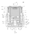
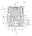
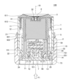
- FIGS. 7A to 7C are cross-sectional views taken along line II in FIG. 2 for explaining the operation of the container when removing the inner container 1 from the outer container 2.
- FIG. 7A to 7C are cross-sectional views taken along line II in FIG. 2 for explaining the operation of the container when removing the inner container 1 from the outer container 2.
- FIG. 7A shows a state in which the contents housed in the container 100 have been used up.
- the states shown in FIGS. 4 and 6 are assumed to be initial states.
- FIG. 7A shows a state in which the content inside the inner container 1 is empty as a result of the content being discharged onto the upper surface of the top surface 3 through the opening 32 and the discharged content being used.
- the stage 6 has reached the rising end position in the inner container 1 (the position where the gate valve 61 of the stage 6 and the top surface 3 are in contact).
- the upper member 731 of the pushing member 7 is in contact with the elastic portion 25 of the outer container 2 and the inner peripheral surface of the outer container 2, and the elastic portion 25 of the outer container 2 is in contact with the diameter. Since the elastic portion 25 cannot be elastically deformed outward, the engagement between the elastic portion 25 and the projection 14 of the inner container 1 is maintained. Therefore, from the initial state to this state, the inner container 1 does not come off from the outer container 2 even if it is pulled by an upward force, so that it is possible to prevent the inner container 1 from accidentally coming off from the outer container 2. . Also, the male screw 54 on the upper part of the slide 5 is screwed with the female screw 622 on the lower part of the stage 6 .
- FIG. 7B shows a state where the pushing member 7 has been pushed to a position where it abuts against the lower end of the inner container 1 .
- the contact surface 721 of the pushing member 7 slides upward along the contact surface 55 of the slide 5
- the contact surface 55 of the slide 5 receives a radially inward force (an additional force applied to the slide 5 ).
- the semi-cylindrical members 51, 52 of the slide 5 are close to each other.
- the diameter of the slide 5 in one direction (the length in the horizontal direction of the paper surface in FIG.
- the elastic portion 25 of the outer container 2 becomes operable (elastically deformable) radially outward.
- the projection 251 of the elastic portion 25 of the outer container 2 and the projection 14 of the inner container 1 are kept engaged with each other. 25 and the projection 14 of the inner container 1 can be released.
- FIG. 7C shows a state in which the pushing member 7 is pushed further to the upper limit position from the state shown in FIG. 7B.
- an upward external force F1 is applied to the inner container 1 . Since the elastic portion 25 of the outer container 2 can move radially outward, the projection 14 of the inner container 1 can climb over the convex portion 251 of the elastic portion 25 from below, The engagement with the protrusion 14 of the inner container 1 is released.
- the contact surface 721 of the pressing member 7 further slides upward along the contact surface 55 of the slide 5.
- a radially inward force is applied to the contact surface 55 of the slide 5, and the pair of semi-cylindrical members 51 and 52 of the slide 5 come closer together.
- the diameter of the slide 5 in one direction is smaller than the inner diameter of the stage 6, and the distance between the male thread 54 of the slide 5 and the female thread 622 of the stage 6 is increased.
- the inner container 1 can be removed from the outer container 2 by lifting the inner container 1 upward.
- the stage 6 , the top surface 3 , and the valve body 8 are integrated with the inner container 1 .
- the inner container 1 When attaching another inner container 1 to the outer container 2 , the inner container 1 is inserted into the opening 21 of the outer container 2 and pushed in, so that the protrusions 14 of the inner container 1 are aligned with the convex portions 251 of the elastic portion 25 of the outer container 2 . get over and engage.
- the pushing member 7 pushes the inner container 1 down to the lower operating limit position, the upper member 731 of the engaging portion 73 of the pushing member 7 is pushed into the gap between the elastic portion 25 of the outer container 2 and the inner peripheral surface of the outer container 2 . and contacts the elastic portion 25 of the outer container 2 and the inner peripheral surface of the outer container 2 .
- the semi-cylindrical members 51, 52 of the slide 5 are separated from each other.
- the diameter of the slide 5 in one direction becomes substantially the same as the inner diameter of the stage 6, and the male screw 54 of the slide 5 and the female screw 622 of the stage 6 are screwed together. , the initial state is reached, and the replacement of the inner container 1 is completed.
- the inner container 1 can be easily removed from the outer container 2 with a one-touch operation of pushing the push-in member 7 . Therefore, even if the contents are used up, the outer container 2, the slide 5, and the pushing member 7 can be used continuously, and the environmental load can be reduced. Moreover, when each member of the container 100 is made of plastic, the amount of plastic can be reduced. Further, the other inner container 1 can be easily attached to the outer container 2 by a one-touch operation of simply pushing the other inner container 1 into the outer container 2 . Furthermore, when attaching the inner container 1 to the outer container 2, it is not necessary to confirm and align the positions in the circumferential direction of each other, so that the other inner container 1 can be attached more easily.
- the inner container 1 can be removed by pushing the pushing member 7, so that the inner container 1 containing new contents can be replaced during use. Moreover, when it is desired to use different contents, the inner container 1 can be exchanged for another containing different contents.
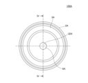
- FIG. 8 is a front view of the container according to the second embodiment
- FIG. 9 is a plan view of the container according to the second embodiment
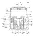
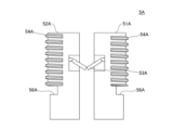
- FIG. 10 is a sectional view taken along line IV-IV of FIG. 11 is a front view of the slide according to the second embodiment
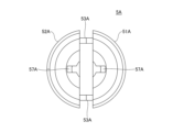
- FIG. 12 is a plan view of the slide according to the second embodiment
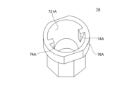
- FIG. 13 is a perspective view of the pushing member according to the second embodiment.
- the inner container 1A has an opening 11A at the top and a peripheral wall 12A as a side surface, and a fitting hole 13A is formed in the center of the bottom surface 16A.
- a slide 5A, a stage 6A, and a pushing member 7A are provided inside the inner container 1A.
- the outer container 2A is a cylindrical container with a bottom having an opening 21A at the top, and has a side wall 22A and a bottom surface 23A. As shown in FIG. 10, a fitting hole 24A is formed in the center of the bottom surface 23A, and a first annular wall 26A is erected upward from the fitting hole 24A. A second annular wall 27A is erected outward in the direction.
- the pushing member 7A is inserted into the fitting hole 24A, and the first annular wall 26A holds the pushing member 7A non-rotatably.
- the shape of the fitting hole 24A in plan view is octagonal, but the shape is not limited to this, and may be any shape according to the shape of the pushing member 7 .
- a pair of protrusions 28A that engage with the slide 5A are formed on the inner peripheral surface of the second annular wall 27A, and the protrusions 28A have contact surfaces that are horizontal in the radial direction.
- the slide 5A is inserted between the first annular wall 26A and the second annular wall 27A, and the engagement between the convex portion 28A and the slide 5A prevents the outer container 2A from moving vertically along the slide 5A, and It is held movably in the radial direction (horizontal direction on the paper surface of FIG. 10).
- the stage 6A has a circular gate valve 61A having the same outer diameter as the inner diameter of the inner container 1 and a rotor 62A that supports the gate valve 61A and rotates together with the inner container 1A.
- the gate valve 61A and the rotating body 62A may be formed separately or integrally.
- the gate valve 61A may have a flat portion 611A and a peripheral wall 612A connected from the flat portion 611A and in close contact with the inner peripheral surface of the peripheral wall 12A of the inner container 1A.
- the gate valve 61A and the inner peripheral surface of the peripheral wall 12A of the inner container 1 are in a state where the gate valve 61A is stationary with respect to the inner peripheral surface of the peripheral wall 12A and when it moves upward with respect to the inner peripheral surface of the peripheral wall 12A. In this state, the contents contained in the inner container 1A are in liquid-tight contact so as not to leak below the gate valve 61A.
- the rotating body 62A of the stage 6A has a cylindrical shape with a top, and a female screw 622A is formed on the inner peripheral surface of the peripheral wall 621A, which is the side surface, to be screwed with the male screw 54A formed on the slide 5A.
- the stage 6A is non-rotatably fixed to the inner container 1A by the same engaging means as in the first embodiment (not shown) or any engaging means, and is rotatably fixed to the outer container 2A. be. In other words, the stage 6A rotates integrally with the inner container 1A.
- the stage 6A rotates together with the relative rotation of the inner container 1A with respect to the outer container 2A, so that the female screw 622A and the male screw 54A of the slide 5A are engaged and interlocked, and the stage 6A rises inside the inner container 1A. arranged as possible. Moreover, when the inner container 1 is removed from the outer container 2 , the stage 6 is removed from the outer container 2 together with the inner container 1 .
- the slide 5A has a cylindrical shape as a whole, and has a male screw 54A that can be screwed with the female screw 622A of the stage 6A on its outer peripheral surface.
- the male screw 54A is formed not on the entire circumference of the outer peripheral surface, but on a symmetrical partial region with a plane including the rotation center axis 10 as a plane of symmetry.
- the male screw 54A is formed in an area of an angle A around the rotation center axis 10 in plan view, like the slide 5 according to the first embodiment shown in FIG.
- Angle A can be any angle in the range of 5° to 100°, for example 70°.
- the slide 5A is composed of a pair of semi-cylindrical members 51A and 52A divided into two in the direction of the rotation center axis 10, and is connected to the outer peripheral surface of the semi-cylindrical member 51A and the outer peripheral surface of the semi-cylindrical member 52A and is extendable in the radial direction. and a slide biasing member 53A.
- the slide urging member 53A may be made of metal or resin.
- a pair of links whose both ends are rotatably fixed and whose central portion is connected by a link, and a direction to open the link between the pair of links. It may be a configuration in which a spring that biases (in the direction of 180°) is interposed.
- the slide biasing member 53A may have a leaf spring structure or the like in which the central portion is bent and an elastic force acts in the direction in which the bending is opened.
- the slide biasing member 53A may have any configuration as long as it biases the pair of semi-cylindrical members 51A and 52A radially outward. As a result, the semi-cylindrical members 51A and 52A can move away from each other or approach each other in one direction perpendicular to the rotation center axis 10 (horizontal direction on the paper surface of FIG. 10).
- the slide 5A has at least a pair of stepped portions 56A that engage with the convex portions 28A of the outer container 2A at its lower end.
- the step portion 56A has a radially horizontal contact surface. Since the stepped portion 56A and the convex portion 28A of the outer container 2A contact and engage with each other on their contact surfaces that are horizontal in the radial direction, the contact surface of the stepped portion 56A is positioned on the contact surface of the convex portion 28A. It is slidable in the radial direction. Thereby, the slide 5A is fixed to the outer container 2A so as to be immovable in the vertical direction and movable in the radial direction.
- the slide 5A has an engagement hole 57A with which a protrusion 74A of the pushing member 7A, which will be described later, engages.
- Other configurations are the same as those of the slide 5 of the first embodiment.
- the pushing member 7A has a cylindrical shape with a bottom, and has a positioning shape with a polygonal cross-sectional shape in the radial direction of the outer shape. As a result, the pushing member 7A is non-rotatably fixed to the outer container 2A.
- the positioning shape may have a cross-sectional shape other than a polygonal shape in the radial direction, for example, a key and a key groove, and any shape as long as the pushing member 7A is non-rotatably fixed to the outer container 2A. good.
- the pushing member 7A has a flange portion 76A protruding radially outward from its upper portion.
- a contact surface 721A that contacts the contact surface of the slide 5A is formed on the inner peripheral surface of the pushing member 7A. It is an inclined surface that is inclined in a direction approaching the rotation center axis 10 toward the bottom surface 23A side of.
- a pair of protrusions 74A are provided on the inner peripheral surface of the pushing member 7A.
- a biasing member 75A that biases the pressing member 7A in the vertical direction may be provided at the bottom inside the pushing member 7A. Since the biasing member 75A always applies a downward force to the pushing member 7A by its elastic force, the bottom surface 71A of the pushing member 7A is kept substantially flush with the bottom surface 23A of the outer container 2A.
- the pushing member 7A is inserted inside the first annular wall 26A of the outer container 2A.
- the cross-sectional shape of the first annular wall 26A of the outer container 2A has the same positioning shape as the cross-sectional shape in the radial direction of the outer shape of the pushing member 7A, and the pushing member 7A is non-rotatably fixed to the first annular wall 26A.
- the slide 5A is attached to the pushing member 7A so that the contact surface 721A and the contact surface of the slide 5A are in contact with each other.
- the pushing member 7A By engaging the projection 74A with the engagement hole 57A of the slide 5A, the pushing member 7A can fix the slide 5A so that it cannot rotate. As a result, the pushing member 7A and the slide 5A rotate together with the rotation of the outer container 2A.
- the pressing member 7A always receives a downward force as a component force of the radially outward force from the slide 5A on the contact surface 721A, which is an inclined surface. It is possible to maintain a substantially flush state with respect to the bottom surface 23A of 2A. Furthermore, since the biasing member 75A assists the downward force exerted by the slide 5A, the bottom surface 71A can be reliably maintained substantially flush with the bottom surface 23A of the outer container 2A. Due to this downward force of the biasing member 75A, the bottom surface 71A of the pushing member 7A pushes against the bottom surface 23A of the outer container 2 particularly when the inner container 1A is newly inserted into the outer container 2A and held in the outer container 2A. On the other hand, it is possible to reliably maintain the substantially flush state.
- the top surface 3A has an opening 32A for discharging the contents to the outside.
- the top surface 3A may have an outer peripheral wall 33A for external fitting with the inner container 1A, and may also have an inner peripheral wall 31A inside the peripheral wall 12A of the inner container 1A.
- the outer peripheral wall 33A may not be provided, and only the inner peripheral wall 31A may be provided.
- the container 100A according to the second embodiment also has the same effects as the container 100 according to the first embodiment.
- the present invention includes the following aspects.
- the inner container has a protrusion on the outer peripheral surface of the lower part,
- the outer container has an elastic portion that engages with the projection, and a fitting hole that the pushing member fits in the bottom surface,
- the slide has a contact surface that contacts the pressing portion
- the pressing portion and the contact surface have inclined surfaces contacting each other,
- the slide has a pair of semi-cylindrical members divided into two by a plane including the rotation center axis,
- the pair of semi-cylindrical members are disposed on the bottom surface of the outer container so as to be radially movable, and are always biased by biasing forces in directions away from each other,
- the pair of semi-cylindrical members is formed with the male screw that can be screwed with the female screw, Aspect 1 or 2, wherein the pair of semi-cylindrical members are brought closer to each other against the biasing force and the male screw is disengaged from the female screw by pushing the pressing portion.
Landscapes
- Engineering & Computer Science (AREA)
- Mechanical Engineering (AREA)
- Containers And Packaging Bodies Having A Special Means To Remove Contents (AREA)
- Packages (AREA)
Abstract
本発明の一態様による容器は、内部に内容物を収容可能で、開口を有する内容器と、前記内容器を相対的に回転可能に収容する、開口を有する外容器と、前記内容物を吐出する開口を有し、前記内容器の開口を覆う天面と、雌螺子を有し、前記内容器又は前記外容器の回転により上昇可能なステージと、外周面に前記雌螺子と螺合可能な雄螺子を有し、回転中心軸に直交する一方向の直径が変化可能な円筒状のスライドと、底面と、前記底面から立設される押圧部と、前記底面の両端から立設された係止部とを有する押込部材とを備え、前記内容器は、下部の外周面に突起を有し、前記外容器は、前記突起と係止する弾性部と、底面に前記押込部材が嵌合する嵌合孔とを有し、前記スライドは、前記押圧部と当接する当接面を有し、前記押込部材が押し込まれることにより、前記スライドの前記一方向の直径が小さくなり前記雄螺子と前記雌螺子の螺合が解除される。
Description
本発明は、容器に関する。
従来、中皿の上昇によって内容物を吐出させる回転式の容器が知られている。
例えば、特許文献1に、内部に内容物が収容される有底筒状の容器本体と、容器本体の上端開口部を塞ぐ頂壁部と、容器本体に容器軸回りに回転可能に装着された回転操作体と、容器本体内に上下摺動可能に嵌合され、回転操作体の回転に伴って上昇移動する中皿と、を備えた吐出容器が開示されている。この容器によれば、容器本体に対して回転操作体を容器軸回りに回転させることで中皿を上昇移動させることができるので、容器本体の内部に収容されている内容物を押し上げて頂壁部に形成された吐出口から吐出することができる。
特許文献1に記載の吐出容器は、内容物を使用した後、使い捨てされるものであり、環境負荷低減やプラスチック量削減の観点からは好ましくない。そこで、外容器に収容されたレフィル容器のみを廃棄し、新しいレフィル容器に交換することで、外容器を繰り返し使用可能とした容器が知られている。
繰り返し使用可能な容器として、例えば、特許文献2に、内容物を収容するための有底略筒状のレフィル容器(内容器)と、このレフィル容器を着脱自在に収容する広口容器(外容器)とを備えた二重容器が開示されている。特許文献2に記載の二重容器は、上記レフィル容器の、上記広口容器内にレフィル容器を収容して両者の係合手段と被係合手段とを係合した状態において、広口容器側の各切欠き部に相対する部分に指をかけて内側に押圧するだけで、上記レフィル容器の周壁の、二つの他の領域がそれぞれ撓んで外側に膨出し、互いに向かい合う二つの領域が互いに接近して、広口容器とレフィル容器との係合が簡単に外れるため、スムーズにレフィル容器を着脱することができるものである。
しかしながら、引用文献2の二重容器では、レフィル容器の周壁を撓ませるのに十分な力が必要となり、利便性に欠ける点がある。
上記の点に鑑みて、本発明の一態様は、回転式の容器において、外容器から内容器を簡便に取り外し交換可能な容器を提供することを目的とする。
本発明の一態様による容器は、内部に内容物を収容可能で、開口を有する内容器と、前記内容器を相対的に回転可能に収容する、開口を有する外容器と、前記内容物を吐出する開口を有し、前記内容器の開口を覆う天面と、雌螺子を有し、前記内容器又は前記外容器の回転により上昇可能なステージと、外周面に前記雌螺子と螺合可能な雄螺子を有し、回転中心軸に直交する一方向の直径が変化可能な円筒状のスライドと、底面と、前記底面から立設される押圧部と、前記底面の両端から立設された係止部とを有する押込部材とを備え、前記内容器は、下部の外周面に突起を有し、前記外容器は、前記突起と係止する弾性部と、底面に前記押込部材が嵌合する嵌合孔とを有し、前記スライドは、前記押圧部と当接する当接面を有し、前記押込部材が押し込まれることにより、前記スライドの前記一方向の直径が小さくなり前記雄螺子と前記雌螺子の螺合が解除される。
本発明の一態様によれば、回転式の容器において、外容器から内容器を簡便に取り外し交換可能な容器を提供することができる。
以下、本発明を実施するための形態について図面を参照しながら説明する。なお、説明の理解を容易にするため、各図面において同一の構成要素に対しては同一の符号を付して、重複する説明は省略する場合がある。また、図面における各部材の縮尺は実際とは異なる場合がある。なお、本明細書では、回転中心軸10に直交する方向を径方向、回転中心軸10に沿う軸線方向において、天面3側を上、外容器2の底面23側を下とする。
<第一実施形態>
本発明の第一実施形態による容器について説明する。図1は、第一実施形態による容器の正面図であり、図2は、第一実施形態による容器の平面図であり、図3は、第一実施形態による容器の分解斜視図である。また、図4は、図2のI-I断面図であり、図5は、図4のIII-III断面図であり、図6は、図2のII-II断面図である。
本発明の第一実施形態による容器について説明する。図1は、第一実施形態による容器の正面図であり、図2は、第一実施形態による容器の平面図であり、図3は、第一実施形態による容器の分解斜視図である。また、図4は、図2のI-I断面図であり、図5は、図4のIII-III断面図であり、図6は、図2のII-II断面図である。
図1~図6に示すように、本発明の第一実施形態による容器100は、レフィル(付替え)容器としての内容器1と、内容器1を収容する外容器2と、内容器1の開口11を覆う天面3と、スライド5と、ステージ6と、押込部材7とを備える。
内容器1は、上部が開口した筒状の容器であって、内容物を収容可能である。本実施形態では、内容物として流動物を吐出させる容器である場合について説明するが、内容物として固形物を吐出させる容器であってもよい。
本実施形態による容器100によって吐出される流動物は、少なくとも吐出時に流動性を示し、容器100の開口32から容器100の外部へと押し出すことができれば限定されない。流動物は、液状物、例えば純物質の液体又は液体混合物であってもよい。さらに、流動物は、例えば、溶液、及びエマルジョン、サスペンション等の分散液等であってもよく、ゲル、スラリー、ペースト、クリーム等と呼ばれる状態のものであってよい。流動物は、粉体を含んでいてよいし、粉体を主として含んでいてもよい。流動物は、上記流動物と、窒素、希ガス、空気等の気体とが混合されて泡状(フォーム状)で内容器1に収容されているものであってもよい。また、流動物は、水と同様の粘度、水より高い粘度を有するペースト状又はクリーム状のものであってよい。
流動物は、化粧水、乳液、フェイスクリーム、美容液、洗顔料、クレンジング剤等のスキンケア製品若しくは基礎化粧品、ファンデーション、化粧下地、コンシーラー、リキッドアイシャドー、リキッドチーク、液状リップ製品等のメーキャップ化粧品、日焼け止め剤、ハンドソープ、ボディソープ、ヘアシャンプー、染毛剤、スタイリング剤、ハンドクリーム、ボディクリーム、ボディローション等のパーソナルケア製品(衛生日用品)、フレグランス製品等であってよい。
内容物が固形物である場合、固形物は、特に硬度の高いヘアスティック、ヘアワックス、口紅、固形美容液(例えば、スティック美容液と類似した硬度のもの)などの固形化粧料又は半固形化粧料、固形石鹸等であってよい。また、チーズ、バターなどの食品等であってもよい。
容器100を構成する材料は、特に限定されないが、樹脂材料、金属材料、木製品等が挙げられる。樹脂材料としては、例えば、ポリエチレン(PE)、ポリプロピレン(PP)、ポリスチレン(PS)、ポリエチレンテレフタレート(PET)、ポリ塩化ビニル(PVC)、メラミン樹脂、エポキシ樹脂、又はシリコン樹脂等を用いることができる。これらの樹脂は、1種類単独で使用してもよいし、2種類以上を組み合わせて使用してもよい。
内容器1は、図4及び図6に示すように、上部に開口11と、側面である周壁12とを有し、底には、嵌合孔13が形成され、嵌合孔13から上方に向かって、支持筒部15が立設されている。内容器1の下部(下端部)の外周面には、外容器2と係合する突起14が設けられている。支持筒部15の内周面には、図5に示すように、回転中心軸10方向に延びる複数の凹凸部が周方向に並設されたローレット151(突条151)が形成されている。ローレット151の長さは任意の長さとすることができる。支持筒部15の内側にステージ6が挿入され、ローレット151がステージ6と係合することにより、支持筒部15は、ステージ6を周方向に回転不能に支持する。なお、ステージ6との係合手段は、ローレット151に限らず任意の構成であってよい。
外容器2は、図4及び図6に示すように、上部に開口21を有する有底筒状の容器であって、側面である周壁22と、底面23とを有する。図6に示すように、底面23の中央には、嵌合孔24が形成され、嵌合孔24から上方向に向かって、第1環状壁26が立設され、第1環状壁26の径方向外側に第2環状壁27が立設されている。嵌合孔24には押込部材7が挿入され、第1環状壁26は押込部材7を摺動可能に保持する。本実施形態では、嵌合孔24の平面視形状は、略長方形であるが、これに限らず、押込部材7の形状に合わせて任意の形状とすることができる。第2環状壁27の内周面には、図4に示すように、スライド5と係合する、一対の凸部28が形成され、凸部28は、径方向に水平な当接面を有する。第1環状壁26と第2環状壁27の間には、スライド5が挿入され、凸部28とスライド5(後述する段部56)が係合することにより、外容器2は、スライド5を上下方向に移動不能、且つ径方向(図4の紙面左右方向)に移動可能に保持する。
また、外容器2は、図4に示すように、第2環状壁27の径方向外側に、回転中心軸10を挟んで一対の弾性部25を有している。弾性部25は、上端部に凸部251を有し、径方向外側に撓むように弾性変形可能となっている。凸部251と内容器1の突起14が係合することにより、内容器1に上向きの力を加えない限り不用意に内容器1が外容器2から外れることを防止することができる。外容器2の内径は、内容器1の外径とほぼ一致しており、外容器2は、内容器1を相対的に回転可能に収容する。外容器2の上端は、外容器2に内容器1が収容された状態で、内容器1の上端よりも下に位置し、外容器2から内容器1の周壁12の上部が露出している。これにより、使用者は、一方の手で外容器2を持ち、他方の手で内容器1の周壁12又は天面3を持ち、内容器1又は外容器2を相対的に回転させることができる。
ステージ6は、内容器1又は外容器2の回転により上昇可能であり、ステージ6の上面と内容器1の内面とで内容物を収容する収容部を構成している。ステージ6は、内容器1の内径と同じ外径を有する平面視形状が円形の仕切弁61と、仕切弁61を支持し内容器1と共に回転する回転体62とを有する。仕切弁61と、回転体62は、別体で形成されていてよく、一体成形されていてもよい。仕切弁61は、平坦部611と、平坦部611から連接され、内容器1の周壁12の内周面と密着する周壁612とを有していてよい。仕切弁61と内容器1の周壁12の内周面は、仕切弁61が周壁12の内周面に対して静止している状態及び周壁12の内周面に対して上方向に移動している状態において、内容器1の中に収容される内容物が仕切弁61の下方に漏洩しないように液密状に接触している。
ステージ6の回転体62は、有頂筒状の形状を有し、側面である周壁621の内周面には、スライド5に形成された雄螺子54と螺合する雌螺子622が形成されている。回転体62の周壁621と仕切弁61の周壁612の間には間隙が形成され、間隙に内容器1の支持筒部15が挿入されて、ステージ6は、内容器1に装着される。また、回転体62の周壁621の外周面には、図3に示すように、回転中心軸10方向に延びる複数の突条624が並設されている。突条624が内容器1の支持筒部15のローレット151に係合することにより、ステージ6は、内容器1に対して回転中心軸10方向に移動可能、且つ回転不能に装着される。これにより、ステージ6は、内容器1に対して回転不能に固定されると共に、外容器2に対して回転可能に固定される。換言すると、ステージ6は、内容器1と一体的に回転する。即ち、ステージ6は、外容器2に対する内容器1の相対的な回転と共に回転することで、雌螺子622とスライド5の雄螺子54とが螺合して連動し、内容器1の内部において上昇可能に配設されている。内容器1との係合手段は、複数の突条624とローレット151との係合に限らず、キーとキー溝等、内容器1の係合手段に応じて任意の構成とすることができる。また、内容器1が外容器2から取り外される時、ステージ6は、内容器1と一体となって、外容器2から取り外される。
スライド5は、全体として円筒状の形状を有し、外周面に、ステージ6の雌螺子622と螺合可能な雄螺子54を有し、回転中心軸10に直交する一方向の直径(図4における紙面左右方向)が変化可能となっている。具体的には、スライド5は、後述するように、回転中心軸10に直交する一方向で、2分割された一対の部材が互いに離反又は近接可能となっている。雄螺子54は、図3に示すように2分割された一対の部材の外周面の全周ではなく、回転中心軸10を含む面を対称面として、対称な一部の領域に形成されている。換言すると、雄螺子54は、図5に示すように、一対の部材それぞれにおいて、平面視において回転中心軸10を中心とする角度Aの領域に形成されている。角度Aは、例えば、5°~100°の範囲の任意の角度とすることができ、例えば、70°とすることができる。
スライド5は、図3に示すように、回転中心軸10を含む面で2分割された一対の半円筒部材51、52と、径方向に伸縮可能なスライド付勢部材53とを有する。スライド付勢部材53は、例えば、バネとすることができ、径方向外側に付勢する構成であれば任意の構成とすることができる。この場合、半円筒部材51、52それぞれの外周面の一部に雄螺子54が形成されている。換言すると、半円筒部材51、52は、少なくとも、一方向の直径と直交する直径方向には、雄螺子54が形成されていない。半円筒部材51、52は、半円筒部材51と半円筒部材52の間にスライド付勢部材53が保持された状態で、径方向に移動可能に外容器2の底面に配置され、互いに離反する方向の付勢力によって常時付勢されている。これにより、半円筒部材51、52は、回転中心軸10に直交する一方向に、離反可能又は近接可能となっている。離反したときのスライド5の当該一方向の大凡の直径は、通常は、ステージ6の内径と略同一であるが、近接すると、ステージ6の内径よりも小さくなる。半円筒部材51、52それぞれの雄螺子54は、半円筒部材51、52が互いに離反する方向に付勢された状態で、ステージ6の雌螺子622と螺合可能となっている。半円筒部材51、52が付勢力に抗して互いに近づくと、半円筒部材51、52それぞれの雄螺子54が、ステージ6の雌螺子622から離隔して、雄螺子54と雌螺子622の螺合が解除される。換言すると、スライド5の一対の半円筒部材51、52が互いに近接すると、雄螺子54が雌螺子622から離隔して、雄螺子54と雌螺子622の螺合が解除される。
半円筒部材51は、図4に示すように、径方向に突設されたガイド小片511を有し、ガイド小片511の端部には、凸部512が設けられていてよい。半円筒部材52も、半円筒部材51と同様に、径方向に突設されたガイド小片521を有し、ガイド小片521の端部には、凸部522が設けられていてよい。半円筒部材51のガイド小片511は、半円筒部材52の挿入孔523に挿入され、半円筒部材52のガイド小片521は、半円筒部材51の挿入孔513に挿入される。そして、半円筒部材51の凸部512と半円筒部材52の凸部522が係合する。これにより、半円筒部材51、52の移動方向及び移動距離を規制することができる。
スライド5は、図4に示すように、下端部に少なくとも一対、外容器2の凸部28と係合する段部56を有する。段部56は、径方向に水平な当接面を有する。段部56と外容器2の凸部28とは、径方向に水平な互いの当接面で当接し係合するため、段部56の当接面は、凸部28の当接面上で径方向に摺動可能となっている。これにより、スライド5は、外容器2に対して上下方向に移動不能、且つ径方向に移動可能に固定されている。
また、スライド5は、後述する押込部材7の当接面721と当接する、少なくとも一対の当接面55を有する。当接面55は、上方が径方向外側に傾いた傾斜面、換言すると、外容器2の底面23側に向かうに従い回転中心軸10に近づく方向に傾斜している傾斜面となっている。具体的には、半円筒部材51、52のそれぞれに、当接面55が形成されている。これにより、スライド5の2分割された一対の半円筒部材51、52は、押込部材7の当接面721に沿って、径方向に移動することができる。
押込部材7は、内容器1を他の内容器1に交換するに当たり、外容器2から取り外す時に、使用者によって押込まれる部材である。押込部材7は、底面71と、底面71の中央から立設された押圧部72と、底面71の両端から立設された係止部73とを有する。押圧部72の内周面には、スライド5の当接面55と当接する当接面721が形成され、当接面721は、上方が径方向外側に傾いた傾斜面、換言すると、外容器2の底面23側に向かうに従い回転中心軸10に近づく方向に傾斜している傾斜面となっている。押圧部72は、図6に示すように、外容器2の第1環状壁26の内側に挿入され、外容器2に上下動可能に保持される。押込部材7の底面71は、押込まれる前の状態(容器が通常、使用されている状態。以下、「通常状態」という。)では、外容器2の底面23に対して略面一となっている。押込部材7には、押圧部72の当接面721とスライド5の当接面55が当接するように、スライド5が組付けられる。押込部材7は、通常状態において、傾斜面である当接面721で、スライド5から径方向外向きの力の分力としての下向きの力を受ける。押込部材7は、スライド5から当該下向きの力を常に受けるため、底面71が外容器2の底面23に対して略面一の状態(押込部材7の作動下限位置)を維持することができる。スライド5から受ける下向きの力を補助するために、押込部材7の押圧部72内部の底に、上下方向に付勢する付勢部材を設けてもよい。押込部材7が押込まれると、当接面721がスライド5の当接面55に沿って上方に摺動するため、スライド5の当接面55に径方向内向きの力(スライド5の付勢力に抗する力)がかかり、スライド5の一対の半円筒部材51、52は、回転中心軸10に直交する一方向に互いに近接する。
係止部73は、外容器2の弾性部25が径方向外側に弾性変形することを規制する部材である。係止部73は、押込部材7の底面71から立設された2つの縦部材から延設された上部材731を有する。上部材731は、外容器2の弾性部25と外容器2の内周面との間の距離と同じ大きさの厚みを有し、通常状態では、外容器2の弾性部25及び外容器2の内周面と当接している。これにより、上部材731は、弾性部25が、径方向外側に弾性変形することを抑止している。本実施形態では、係止部73は、2つの縦部材と、上部材731とを有する枠型の構成であるが、これに限らず、例えば、上部に凸部を有する構成であってもよい。また、押込部材7は、外容器2の弾性部25の下端に当接することにより、上方への移動が規制される。換言すると、弾性部25の下端の位置が、押込部材7の作動上限となっている。
押圧部72の外周面には、図6に示すように、少なくとも一対の突起722が設けられている。突起722が、外容器2の第1環状壁26を乗り越え、第1環状壁26の上端に係止することにより、押込部材7が外容器2から脱落することを防止することができる。
天面3は、内容器1の開口11を覆う部材であり、内容物を外部に吐出させるための開口32を有している。天面3は、内容器1に内嵌合させるための内周壁31を有していてもよく、内容器1に外嵌合させる構成としてもよい。また、開口32に弁体8が配置されていてもよい。本実施形態においては、弁体8は、ステージ6の上昇に伴って内容器1に収容された内容物の内圧が高まることで上昇し、上昇した弁体8と天面3との間から、内容物が天面3の上面に吐出される。これにより、使用者は、吐出された使用分の内容物にのみ触れることができるので、未使用分の内容物に触れずに使用することができ、内容物を衛生的に保管することができる。内容物が、固形物である場合、弁体8は設けなくてもよく、天面3の構成を固形物に対応した構成とすることができる。
容器100は、図示されていない蓋体を有していてもよい。蓋体は、例えば、ネジ蓋であってよく、外容器2の周壁22の外周面に形成されている雄螺子と螺合し、内容器1、天面3、及び外容器2の開口21を覆うように固定されていてもよい。蓋体は、ネジ蓋に限らず、例えば、スナップ式でもよい。
次に、内容器1を他の内容器1に交換するに当たり、外容器2から内容器1を取り外す時の容器100の作動について、図7A~図7Cを用いて説明する。図7A~図7Cは、外容器2から内容器1を取り外す時の容器の作動を説明する図2のI-I断面図である。
図7Aは、容器100に収容された内容物を使い切った状態を示す。なお、図4及び図6に示す状態を初期状態とする。まず、図4及び図6に示す初期状態から、内容器1又は外容器2を相対的に回転させると、ステージ6が上昇し、ステージ6の上昇に伴って内容器1に収容された内容物が圧力を受けて上方に押し上げられる。内容物は、弁体8を押し上げ、上昇したステージ6と天面3の間から、天面3の開口32を通じて天面3の上面に吐出される。図7Aは、内容物が開口32を通じて天面3の上面に吐出され、吐出された内容物が使用された結果、内容器1の内部の内容物がなくなった状態を示している。ステージ6は、内容器1内の上昇端位置(ステージ6の仕切弁61と天面3が接する位置)に至っている。
この状態においては、初期状態と同様に、押込部材7の上部材731が、外容器2の弾性部25及び外容器2の内周面と当接しており、外容器2の弾性部25が径方向外側に弾性変形することができないため、弾性部25と内容器1の突起14の係合が維持されている。よって、初期状態からこの状態において、内容器1は、上方向の力で引っ張られても外容器2から外れないため、内容器1が外容器2から不用意に外れることを防止することができる。また、スライド5の上部の雄螺子54は、ステージ6の下部の雌螺子622と螺合している。この状態から、誤って、更に内容器1又は外容器2が回転されても、スライド5の2分割された一対の半円筒部材51、52は近接するため、ステージ6及びスライド5に負荷がかかりにくく、ステージ6及びスライド5が破損することを防止することができる。
次に、図7Aに示す状態で、押込部材7の底面71が押圧される(上向きの外力F1がかかる)。
図7Bは、押込部材7が内容器1の下端と当接する位置まで押込まれた状態を示す。押込部材7の当接面721がスライド5の当接面55に沿って上方に摺動することにより、スライド5の当接面55に径方向内向きの力(スライド5に付加されている付勢力に抗する力)がかかり、スライド5の半円筒部材51、52は互いに近接している。スライド5の一方向の直径(図7Bにおける紙面左右方向の長さ)は、半円筒部材51、52が近接することにより、ステージ6の内径よりも小さくなり、スライド5の雄螺子54とステージ6の雌螺子622との螺合が解除されている。また、押込部材7の係止部73の上部材731は、上方に移動するため、外容器2の弾性部25及び外容器2の内周面から離隔し、係止部73の上部材731と外容器2の弾性部25との係止が解除されている。外容器2の弾性部25と外容器2の内周面の間の上部材731が位置していた場所には、間隙が形成されている。これにより、外容器2の弾性部25は、径方向外側に作動可能(弾性変形可能)な状態となる。この状態においては、外容器2の弾性部25の凸部251と内容器1の突起14が係合した状態が維持されているが、内容器1に上向きの外力F1がかかることにより、弾性部25の凸部251と内容器1の突起14との係合が解除可能となる。
図7Bに示す状態で、押込部材7の底面71が更に押圧される(上向きの外力F1がかかる)。
図7Cは、図7Bに示す状態から、押込部材7が作動上限位置まで更に押込まれた状態を示す。押込部材7が、図7Bに示す状態から、更に押圧されると、内容器1に上向きの外力F1がかかる。外容器2の弾性部25は径方向外側に作動可能な状態であるので、内容器1の突起14は下から弾性部25の凸部251を乗り越えることができ、弾性部25の凸部251と内容器1の突起14との係合が解除されている。
また、押込部材7が、図7Bに示す状態から、更に押圧されることにより、押込部材7の当接面721が、更にスライド5の当接面55に沿って上方に摺動する。これにより、スライド5の当接面55に径方向内向きの力がかかり、スライド5の一対の半円筒部材51、52は更に近接する。スライド5の一方向の直径は、ステージ6の内径より更に小さくなり、スライド5の雄螺子54とステージ6の雌螺子622との距離が大きくなっている。この状態において、内容器1を上方に持ち上げると、内容器1を外容器2から取り外すことができる。なお、ステージ6、天面3、弁体8は内容器1と一体となっている。
他の内容器1を外容器2に取り付ける際は、内容器1を、外容器2の開口21に挿入し押し込むことにより、内容器1の突起14が外容器2の弾性部25の凸部251を乗り越え係合する。押込部材7が作動下限位置に至るまで内容器1を押し込むと、押込部材7の係止部73の上部材731が、外容器2の弾性部25と外容器2の内周面の間の間隙に挿入され、外容器2の弾性部25及び外容器2の内周面と当接する。また、押込部材7の当接面721がスライド5の当接面55に沿って下方に摺動することにより、スライド5の当接面55に付加されていた径方向内向きの力が徐々に解除され、スライド5の半円筒部材51、52は互いに離反する。半円筒部材51、52が互いに離反することにより、スライド5の一方向の直径は、ステージ6の内径とほぼ同一になり、スライド5の雄螺子54とステージ6の雌螺子622とが螺合し、初期状態となり、内容器1の交換が完了する。
以上の構成により、押込部材7を押し込むだけのワンタッチの操作で外容器2から内容器1を簡便に取り外すことができる。よって、内容物を使い切っても、外容器2、スライド5、及び押込部材7を継続して使用することができ、環境負荷を低減することができる。また、容器100の各部材がプラスチック製である場合、プラスチック量を削減することができる。また、他の内容器1を外容器2に押し込むだけのワンタッチの操作で外容器2に他の内容器1を簡便に取り付けることができる。更に、内容器1を外容器2に取り付ける際に、相互の周方向の位置を確認して位置合わせする必要がなく、他の内容器1をより簡便に取り付けることができる。
内容物を使い切った状態でなくても、押込部材7を押し込むことにより、内容器1を取り外すことができるため、使用途中で新しい内容物が収容された内容器1に交換することができる。また、異なる内容物を使用したい場合に、異なる内容物が収容された内容器1に交換することができる。
<第二実施形態>
本発明の第二実施形態による容器について説明する。図8は、第二実施形態による容器の正面図であり、図9は、第二実施形態による容器の平面図であり、図10は、図9のIV-IV断面図である。図11は、第二実施形態によるスライドの正面図であり、図12は、第二実施形態によるスライドの平面図であり、図13は、第二実施形態による押込部材の斜視図である。
本発明の第二実施形態による容器について説明する。図8は、第二実施形態による容器の正面図であり、図9は、第二実施形態による容器の平面図であり、図10は、図9のIV-IV断面図である。図11は、第二実施形態によるスライドの正面図であり、図12は、第二実施形態によるスライドの平面図であり、図13は、第二実施形態による押込部材の斜視図である。
内容器1Aは、図8及び図10に示すように、上部に開口11Aと、側面である周壁12Aとを有し、底面16Aには、中央に嵌合孔13Aが形成されている。嵌合孔13Aには、後述する外容器2Aの第1環状壁26A及び第2環状壁27Aが挿入される。さらに、内容器1Aの内部には、スライド5Aと、ステージ6Aと、押込部材7Aとが設けられている。
外容器2Aは、上部に開口21Aを有する有底筒状の容器であって、側面である周壁22Aと、底面23Aとを有する。図10に示すように、底面23Aの中央には、嵌合孔24Aが形成され、嵌合孔24Aから上方向に向かって、第1環状壁26Aが立設され、第1環状壁26Aの径方向外側に第2環状壁27Aが立設されている。嵌合孔24Aには押込部材7Aが挿入され、第1環状壁26Aは押込部材7Aを回転不能に保持する。本実施形態では、嵌合孔24Aの平面視形状は、八角形であるが、これに限らず、押込部材7の形状に合わせて任意の形状とすることができる。第2環状壁27Aの内周面には、スライド5Aと係合する、一対の凸部28Aが形成され、凸部28Aは、径方向に水平な当接面を有する。第1環状壁26Aと第2環状壁27Aの間には、スライド5Aが挿入され、凸部28Aとスライド5Aが係合することにより、外容器2Aは、スライド5Aを上下方向に移動不能、且つ径方向(図10の紙面左右方向)に移動可能に保持する。
ステージ6Aは、内容器1の内径と同じ外径を有する平面視形状が円形の仕切弁61Aと、仕切弁61Aを支持し内容器1Aと共に回転する回転体62Aとを有する。仕切弁61Aと、回転体62Aは、別体で形成されていてよく、一体成形されていてもよい。仕切弁61Aは、平坦部611Aと、平坦部611Aから連接され、内容器1Aの周壁12Aの内周面と密着する周壁612Aとを有していてよい。仕切弁61Aと内容器1の周壁12Aの内周面は、仕切弁61Aが周壁12Aの内周面に対して静止している状態及び周壁12Aの内周面に対して上方向に移動している状態において、内容器1Aの中に収容される内容物が仕切弁61Aの下方に漏洩しないように液密状に接触している。
ステージ6Aの回転体62Aは、有頂筒状の形状を有し、側面である周壁621Aの内周面には、スライド5Aに形成された雄螺子54Aと螺合する雌螺子622Aが形成されている。ステージ6Aは、内容器1Aに対して、図示しない第一実施形態と同様の係合手段、又は任意の係合手段によって回転不能に固定されると共に、外容器2Aに対して回転可能に固定される。換言すると、ステージ6Aは、内容器1Aと一体的に回転する。即ち、ステージ6Aは、外容器2Aに対する内容器1Aの相対的な回転と共に回転することで、雌螺子622Aとスライド5Aの雄螺子54Aとが螺合して連動し、内容器1Aの内部において上昇可能に配設されている。また、内容器1が外容器2から取り外される時、ステージ6は、内容器1と一体となって、外容器2から取り外される。
スライド5Aは、図11及び図12に示すように、全体として円筒状の形状を有し、外周面に、ステージ6Aの雌螺子622Aと螺合可能な雄螺子54Aを有する。雄螺子54Aは、外周面の全周ではなく、回転中心軸10を含む面を対称面として、対称な一部の領域に形成されている。換言すると、雄螺子54Aは、図5に示す第一実施形態によるスライド5と同様に、平面視において回転中心軸10を中心とする角度Aの領域に形成されている。角度Aは、5°~100°の範囲の任意の角度とすることができ、例えば、70°とすることができる。
スライド5Aは、回転中心軸10方向に2分割された一対の半円筒部材51A、52Aと、半円筒部材51Aの外周面と半円筒部材52Aの外周面に接続された、径方向に伸縮可能なスライド付勢部材53Aとを有する。スライド付勢部材53Aは、金属製あるいは、樹脂製であってよく、例えば、両端が回動自在に固定され、中央部がリンク結合された一対のリンクと、一対のリンク間にリンクを開く方向(180°になる方向)に付勢するバネを介在させた構成等であってよい。又は、スライド付勢部材53Aは、中央部が屈曲して屈曲が開く方向に弾性力が作用する板バネ構造等であってよい。スライド付勢部材53Aは、一対の半円筒部材51A、52Aを径方向外側に付勢する構成であれば任意の構成とすることができる。これにより、半円筒部材51A、52Aは、回転中心軸10に直交する一方向(図10における紙面左右方向)で、互いに離反可能又は近接可能となっている。
スライド5Aは、下端部に少なくとも一対、外容器2Aの凸部28Aと係合する段部56Aを有する。段部56Aは、径方向に水平な当接面を有する。段部56Aと外容器2Aの凸部28Aとは、径方向に水平な互いの当接面で当接し係合するため、段部56Aの当接面は、凸部28Aの当接面上で径方向に摺動可能となっている。これにより、スライド5Aは、外容器2Aに対して上下方向に移動不能、且つ径方向に移動可能に固定されている。
スライド5Aは、図12に示すように、後述する押込部材7Aの凸部74Aが係合する、係合孔57Aを有する。その他の構成については、第一実施形態のスライド5と同様である。
押込部材7Aは、図13に示すように、有底筒状の形状を有し、外形の径方向における断面形状が多角形となる位置決め形状が形成されている。これにより、押込部材7Aが、外容器2Aに対して回転不能に固定される。なお、位置決め形状は、径方向における断面形状が多角形以外でもよく、例えば、キーとキー溝とでもよく、押込部材7Aが外容器2Aに回転不能に固定される形状であれば、いかなる形状でもよい。
押込部材7Aは、上部に径方向外側に突出した鍔部76Aを有する。押込部材7Aの内周面には、スライド5Aの当接面と当接する当接面721Aが形成され、当接面721Aは、上方が径方向外側に傾いた傾斜面、換言すると、外容器2Aの底面23A側に向かうに従い回転中心軸10に近づく方向に傾斜している傾斜面となっている。また、押込部材7Aの内周面には、一対の凸部74Aが設けられている。また、押込部材7Aの内部の底には、図10に示すように、上下方向に付勢する付勢部材75Aが設けられていてよい。付勢部材75Aは、弾性力により、押込部材7Aに常に下向きの力を付与するため、押込部材7Aの底面71Aを外容器2Aの底面23Aに対して略面一の状態に維持する。
押込部材7Aは、外容器2Aの第1環状壁26Aの内側に挿入される。外容器2Aの第1環状壁26Aの断面形状は、押込部材7Aの外形の径方向における断面形状と同じ位置決め形状を有し、押込部材7Aは、第1環状壁26Aに回転不能に固定されている。また、押込部材7Aの鍔部76Aが、第1環状壁26Aの上端に係止することにより、押込部材7Aが外容器2Aから脱落することを防止することができる。更に、押込部材7Aには、当接面721Aとスライド5Aの当接面が当接するように、スライド5Aが組付けられる。凸部74Aとスライド5Aの係合孔57Aが係合することにより、押込部材7Aは、スライド5Aを回転不能に固定することができる。これにより、外容器2Aの回転と共に、押込部材7A及びスライド5Aが回転する。
また、押込部材7Aは、通常の使用状態において、傾斜面である当接面721Aで、スライド5Aから径方向外向きの力の分力としての下向きの力を常に受けるため、底面71Aが外容器2Aの底面23Aに対して略面一の状態を維持することができる。更に、付勢部材75Aが、スライド5Aによる下向きの力を補助するため、底面71Aが外容器2Aの底面23Aに対して略面一の状態を確実に維持することができる。この付勢部材75Aの下向きの力により、特に内容器1Aを、新たに外容器2Aに挿入して外容器2A内に保持する際に、押込部材7Aの底面71Aが外容器2の底面23Aに対して略面一の状態を確実に維持させることが可能となる。
天面3Aは、内容物を外部に吐出させるための開口32Aを有している。天面3Aは、内容器1Aに外嵌合させるための外周壁33Aを有していてよく、内容器1Aの周壁12Aの内側にも内周壁31Aを有していてよい。天面3Aを内容器1Aに内嵌合させる場合は、外周壁33Aを設けず、内周壁31Aのみ設ける構成とすることができる。
以上の構成により、第二実施形態による容器100Aにおいても、第一実施形態による容器100と同様の効果を奏する。
(本発明の態様)
本発明は、以下の態様を含む。
<態様1>
内部に内容物を収容可能で、開口を有する内容器と、
前記内容器を相対的に回転可能に収容する、開口を有する外容器と、
前記内容物を吐出する開口を有し、前記内容器の開口を覆う天面と、
雌螺子を有し、前記内容器又は前記外容器の回転により上昇可能なステージと、
外周面に前記雌螺子と螺合可能な雄螺子を有し、回転中心軸に直交する一方向の直径が変化可能な円筒状のスライドと、
底面と、前記底面から立設される押圧部と、前記底面の両端から立設された係止部とを有する押込部材とを備え、
前記内容器は、下部の外周面に突起を有し、
前記外容器は、前記突起と係止する弾性部と、底面に前記押込部材が嵌合する嵌合孔とを有し、
前記スライドは、前記押圧部と当接する当接面を有し、
前記押込部材が押し込まれることにより、前記スライドの前記一方向の直径が小さくなり前記雄螺子と前記雌螺子の螺合が解除される、容器。
<態様2>
前記押圧部及び前記当接面は、互いに当接する傾斜面を有し、
前記押圧部及び前記当接面の前記傾斜面は、前記外容器の底面側に向かうに従い前記回転中心軸に近づく方向に傾斜している、態様1に記載の容器。
<態様3>
前記スライドは、前記回転中心軸を含む面で2分割された一対の半円筒部材を有し、
前記一対の半円筒部材は、径方向に移動可能に前記外容器の底面に配置されると共に、互いに離反する方向の付勢力によって常時付勢され、
前記一対の半円筒部材には、それぞれ前記雌螺子と螺合可能な前記雄螺子が形成され、
前記押圧部が押し込まれることにより、前記一対の半円筒部材は、前記付勢力に抗して互いに近接し前記雄螺子は前記雌螺子との螺合が解除される、態様1又は2に記載の容器。
<態様4>
前記半円筒部材は、少なくとも、前記一方向の直径と直交する直径方向には、前記雄螺子が形成されていない、態様3に記載の容器。
<態様5>
前記雄螺子と前記雌螺子の螺合が解除されると共に、前記弾性部と前記係止部との係止が解除され、前記弾性部と前記突起との係合が解除可能となる、態様1乃至4のいずれか一つに記載の容器。
<態様6>
前記雄螺子と前記雌螺子の螺合が解除されると共に前記弾性部と前記突起との係合が解除可能となると、少なくとも、前記内容器と前記ステージは、前記外容器から取り外し可能である、態様1乃至5のいずれか一つに記載の容器。
以上の通り、実施形態を説明したが、上記実施形態は、例として提示したものであり、上記実施形態により本発明が限定されるものではない。上記実施形態は、その他の様々な形態で実施されることが可能であり、発明の要旨を逸脱しない範囲で、種々の組み合わせ、省略、置き換え、変更などを行うことが可能である。これら実施形態やその変形は、発明の範囲や要旨に含まれると共に、特許請求の範囲に記載された発明とその均等の範囲に含まれる。
本国際出願は2021年10月11日に出願された日本国特許出願2021-166935号に基づく優先権を主張するものであり、その全内容を参照によりここに援用する。
1、1A 内容器
11、11A 開口
12、12A 周壁
13、13A 嵌合孔
14 突起
15 支持筒部
151 ローレット
16A 底面
2、2A 外容器
21、21A 開口
22、22A 周壁
23、23A 底面
24、24A 嵌合孔
25 弾性部
251 凸部
26、26A 第1環状壁
27、27A 第2環状壁
28、28A 凸部
3、3A 天面
31、31A 内周壁
32、32A 開口
33A 外周壁
5、5A スライド
51、52、51A、52A 半円筒部材
511、521 ガイド小片
512、522 凸部
513、523 挿入孔
53、53A スライド付勢部材
54、54A 雄螺子
55 当接面
56、56A 段部
57A 係合孔
6、6A ステージ
61、61A 仕切弁
611、611A 平坦部
612、612A 周壁
62、62A 回転体
621、621A 周壁
622、622A 雌螺子
624 突条
7、7A 押込部材
71、71A 底面
72 押圧部
721、721A 当接面
722 突起
73 係止部
731 上部材
74A 凸部
75A 付勢部材
76A 鍔部
8、8A 弁体
10 回転中心軸
100、100A 容器
Claims (6)
- 内部に内容物を収容可能で、開口を有する内容器と、
前記内容器を相対的に回転可能に収容する、開口を有する外容器と、
前記内容物を吐出する開口を有し、前記内容器の開口を覆う天面と、
雌螺子を有し、前記内容器又は前記外容器の回転により上昇可能なステージと、
外周面に前記雌螺子と螺合可能な雄螺子を有し、回転中心軸に直交する一方向の直径が変化可能な円筒状のスライドと、
底面と、前記底面から立設される押圧部と、前記底面の両端から立設された係止部とを有する押込部材とを備え、
前記内容器は、下部の外周面に突起を有し、
前記外容器は、前記突起と係止する弾性部と、底面に前記押込部材が嵌合する嵌合孔とを有し、
前記スライドは、前記押圧部と当接する当接面を有し、
前記押込部材が押し込まれることにより、前記スライドの前記一方向の直径が小さくなり前記雄螺子と前記雌螺子の螺合が解除される、容器。 - 前記押圧部及び前記当接面は、互いに当接する傾斜面を有し、
前記押圧部及び前記当接面の前記傾斜面は、前記外容器の底面側に向かうに従い前記回転中心軸に近づく方向に傾斜している、請求項1に記載の容器。 - 前記スライドは、前記回転中心軸を含む面で2分割された一対の半円筒部材を有し、
前記一対の半円筒部材は、径方向に移動可能に前記外容器の底面に配置されると共に、互いに離反する方向の付勢力によって常時付勢され、
前記一対の半円筒部材には、それぞれ前記雌螺子と螺合可能な前記雄螺子が形成され、
前記押圧部が押し込まれることにより、前記一対の半円筒部材は、前記付勢力に抗して互いに近接し前記雄螺子は前記雌螺子との螺合が解除される、請求項1又は2に記載の容器。 - 前記半円筒部材は、少なくとも、前記一方向の直径と直交する直径方向には、前記雄螺子が形成されていない、請求項3に記載の容器。
- 前記雄螺子と前記雌螺子の螺合が解除されると共に、前記弾性部と前記係止部との係止が解除され、前記弾性部と前記突起との係合が解除可能となる、請求項1又は2に記載の容器。
- 前記雄螺子と前記雌螺子の螺合が解除されると共に前記弾性部と前記突起との係合が解除可能となると、少なくとも、前記内容器と前記ステージは、前記外容器から取り外し可能である、請求項5に記載の容器。
Applications Claiming Priority (2)
| Application Number | Priority Date | Filing Date | Title |
|---|---|---|---|
| JP2021-166935 | 2021-10-11 | ||
| JP2021166935A JP2024161326A (ja) | 2021-10-11 | 2021-10-11 | 容器 |
Publications (1)
| Publication Number | Publication Date |
|---|---|
| WO2023063071A1 true WO2023063071A1 (ja) | 2023-04-20 |
Family
ID=85988285
Family Applications (1)
| Application Number | Title | Priority Date | Filing Date |
|---|---|---|---|
| PCT/JP2022/035868 Ceased WO2023063071A1 (ja) | 2021-10-11 | 2022-09-27 | 容器 |
Country Status (2)
| Country | Link |
|---|---|
| JP (1) | JP2024161326A (ja) |
| WO (1) | WO2023063071A1 (ja) |
Citations (2)
| Publication number | Priority date | Publication date | Assignee | Title |
|---|---|---|---|---|
| JP2012111525A (ja) * | 2010-11-25 | 2012-06-14 | Yoshino Kogyosho Co Ltd | 吐出容器 |
| CN205076275U (zh) * | 2015-10-15 | 2016-03-09 | 锦奈化妆品(上海)有限公司 | 一种膏霜瓶 |
-
2021
- 2021-10-11 JP JP2021166935A patent/JP2024161326A/ja active Pending
-
2022
- 2022-09-27 WO PCT/JP2022/035868 patent/WO2023063071A1/ja not_active Ceased
Patent Citations (2)
| Publication number | Priority date | Publication date | Assignee | Title |
|---|---|---|---|---|
| JP2012111525A (ja) * | 2010-11-25 | 2012-06-14 | Yoshino Kogyosho Co Ltd | 吐出容器 |
| CN205076275U (zh) * | 2015-10-15 | 2016-03-09 | 锦奈化妆品(上海)有限公司 | 一种膏霜瓶 |
Also Published As
| Publication number | Publication date |
|---|---|
| JP2024161326A (ja) | 2024-11-19 |
Similar Documents
| Publication | Publication Date | Title |
|---|---|---|
| CN101536833A (zh) | 用于封装尤其是化妆品的产品的系统的保护设备 | |
| US10858170B2 (en) | Dual dispensing cosmetic container | |
| US9814294B2 (en) | Applicator device for a product in stick form and use of same | |
| US20030192892A1 (en) | Case | |
| CZ2001998A3 (cs) | Dávkovací systém ukládacího kontejneru s uzávěrem | |
| US5116156A (en) | Roller-type material applicator | |
| WO1999044464A1 (en) | Liquefied cosmetic container | |
| JP2006043470A (ja) | 可変量が供給されるのを可能にする包装及びディスペンサ装置 | |
| WO2022196420A1 (ja) | 容器 | |
| CN105035546A (zh) | 按压型分配容器 | |
| US7350525B2 (en) | Device for packaging and applying a substance such as a cosmetic or another care product | |
| JP7511454B2 (ja) | スポイト容器 | |
| KR200487039Y1 (ko) | 교체용 에어쿠션 유닛의 덮개 결합 구조 | |
| KR20200121092A (ko) | 화장품 용기 | |
| JP2024161326A (ja) | 容器 | |
| JP2024077321A (ja) | 容器 | |
| WO2023063072A1 (ja) | 容器 | |
| JP2025542434A (ja) | スペースリッド | |
| JP6768583B2 (ja) | 塗布容器 | |
| CN113271812A (zh) | 棒状材送出容器 | |
| JP7421940B2 (ja) | 塗布容器 | |
| JP7665884B2 (ja) | キャップ構造体及び容器 | |
| JP2025088489A (ja) | チューブ容器 | |
| JP7584381B2 (ja) | 塗布容器 | |
| JP7348620B2 (ja) | 化粧料容器 |
Legal Events
| Date | Code | Title | Description |
|---|---|---|---|
| 121 | Ep: the epo has been informed by wipo that ep was designated in this application |
Ref document number: 22880767 Country of ref document: EP Kind code of ref document: A1 |
|
| NENP | Non-entry into the national phase |
Ref country code: DE |
|
| 122 | Ep: pct application non-entry in european phase |
Ref document number: 22880767 Country of ref document: EP Kind code of ref document: A1 |
|
| NENP | Non-entry into the national phase |
Ref country code: JP |