WO2023054692A1 - Vapor chamber, electronic device and vapor chamber production method - Google Patents
Vapor chamber, electronic device and vapor chamber production method Download PDFInfo
- Publication number
- WO2023054692A1 WO2023054692A1 PCT/JP2022/036767 JP2022036767W WO2023054692A1 WO 2023054692 A1 WO2023054692 A1 WO 2023054692A1 JP 2022036767 W JP2022036767 W JP 2022036767W WO 2023054692 A1 WO2023054692 A1 WO 2023054692A1
- Authority
- WO
- WIPO (PCT)
- Prior art keywords
- region
- sheet
- vapor chamber
- steam
- flow path
- Prior art date
Links
- 238000004519 manufacturing process Methods 0.000 title claims description 32
- 239000007788 liquid Substances 0.000 claims description 407
- 238000005452 bending Methods 0.000 claims description 312
- 239000012530 fluid Substances 0.000 claims description 202
- 238000000034 method Methods 0.000 claims description 40
- 230000003014 reinforcing effect Effects 0.000 claims description 40
- 230000008569 process Effects 0.000 claims description 29
- 238000002360 preparation method Methods 0.000 claims description 18
- 238000005304 joining Methods 0.000 claims description 16
- 238000010030 laminating Methods 0.000 claims description 2
- 238000001704 evaporation Methods 0.000 description 124
- 230000008020 evaporation Effects 0.000 description 121
- 238000004891 communication Methods 0.000 description 104
- 238000012986 modification Methods 0.000 description 84
- 230000004048 modification Effects 0.000 description 84
- 238000009833 condensation Methods 0.000 description 58
- 230000005494 condensation Effects 0.000 description 58
- 230000009471 action Effects 0.000 description 53
- 239000000463 material Substances 0.000 description 39
- 238000005530 etching Methods 0.000 description 38
- 238000012546 transfer Methods 0.000 description 33
- 238000002347 injection Methods 0.000 description 24
- 239000007924 injection Substances 0.000 description 24
- 230000007423 decrease Effects 0.000 description 16
- 230000005855 radiation Effects 0.000 description 16
- 230000000149 penetrating effect Effects 0.000 description 14
- 239000007769 metal material Substances 0.000 description 13
- 229910000881 Cu alloy Inorganic materials 0.000 description 11
- 101100123346 Neurospora crassa (strain ATCC 24698 / 74-OR23-1A / CBS 708.71 / DSM 1257 / FGSC 987) hh2a gene Proteins 0.000 description 11
- 238000001816 cooling Methods 0.000 description 11
- RYGMFSIKBFXOCR-UHFFFAOYSA-N Copper Chemical compound [Cu] RYGMFSIKBFXOCR-UHFFFAOYSA-N 0.000 description 8
- 239000010949 copper Substances 0.000 description 8
- 238000010586 diagram Methods 0.000 description 8
- 229910052802 copper Inorganic materials 0.000 description 7
- 230000017525 heat dissipation Effects 0.000 description 7
- OKKJLVBELUTLKV-UHFFFAOYSA-N Methanol Chemical compound OC OKKJLVBELUTLKV-UHFFFAOYSA-N 0.000 description 6
- 230000000694 effects Effects 0.000 description 6
- 238000007789 sealing Methods 0.000 description 6
- 230000007797 corrosion Effects 0.000 description 5
- 238000005260 corrosion Methods 0.000 description 5
- 238000009792 diffusion process Methods 0.000 description 5
- XLYOFNOQVPJJNP-UHFFFAOYSA-N water Substances O XLYOFNOQVPJJNP-UHFFFAOYSA-N 0.000 description 5
- CSCPPACGZOOCGX-UHFFFAOYSA-N Acetone Chemical compound CC(C)=O CSCPPACGZOOCGX-UHFFFAOYSA-N 0.000 description 4
- LFQSCWFLJHTTHZ-UHFFFAOYSA-N Ethanol Chemical compound CCO LFQSCWFLJHTTHZ-UHFFFAOYSA-N 0.000 description 4
- 230000000994 depressogenic effect Effects 0.000 description 4
- 238000013461 design Methods 0.000 description 4
- 230000006866 deterioration Effects 0.000 description 4
- 230000035515 penetration Effects 0.000 description 4
- 239000011148 porous material Substances 0.000 description 4
- 238000003860 storage Methods 0.000 description 4
- 238000009834 vaporization Methods 0.000 description 4
- 230000008016 vaporization Effects 0.000 description 4
- 238000003466 welding Methods 0.000 description 4
- RTAQQCXQSZGOHL-UHFFFAOYSA-N Titanium Chemical compound [Ti] RTAQQCXQSZGOHL-UHFFFAOYSA-N 0.000 description 3
- 238000013459 approach Methods 0.000 description 3
- 230000015572 biosynthetic process Effects 0.000 description 3
- -1 etc. Substances 0.000 description 3
- 230000014759 maintenance of location Effects 0.000 description 3
- 230000000704 physical effect Effects 0.000 description 3
- 238000012545 processing Methods 0.000 description 3
- 239000010936 titanium Substances 0.000 description 3
- 229910052719 titanium Inorganic materials 0.000 description 3
- PXHVJJICTQNCMI-UHFFFAOYSA-N Nickel Chemical compound [Ni] PXHVJJICTQNCMI-UHFFFAOYSA-N 0.000 description 2
- ATJFFYVFTNAWJD-UHFFFAOYSA-N Tin Chemical compound [Sn] ATJFFYVFTNAWJD-UHFFFAOYSA-N 0.000 description 2
- 230000001154 acute effect Effects 0.000 description 2
- 239000002390 adhesive tape Substances 0.000 description 2
- 239000000956 alloy Substances 0.000 description 2
- 229910052782 aluminium Inorganic materials 0.000 description 2
- XAGFODPZIPBFFR-UHFFFAOYSA-N aluminium Chemical compound [Al] XAGFODPZIPBFFR-UHFFFAOYSA-N 0.000 description 2
- 239000000470 constituent Substances 0.000 description 2
- ORTQZVOHEJQUHG-UHFFFAOYSA-L copper(II) chloride Chemical compound Cl[Cu]Cl ORTQZVOHEJQUHG-UHFFFAOYSA-L 0.000 description 2
- 238000009826 distribution Methods 0.000 description 2
- 230000020169 heat generation Effects 0.000 description 2
- 101150042831 hh2b gene Proteins 0.000 description 2
- 229910001092 metal group alloy Inorganic materials 0.000 description 2
- 239000000203 mixture Substances 0.000 description 2
- 238000005192 partition Methods 0.000 description 2
- 238000000206 photolithography Methods 0.000 description 2
- 238000003825 pressing Methods 0.000 description 2
- 230000002787 reinforcement Effects 0.000 description 2
- 230000000717 retained effect Effects 0.000 description 2
- 239000004065 semiconductor Substances 0.000 description 2
- 239000000243 solution Substances 0.000 description 2
- 239000010935 stainless steel Substances 0.000 description 2
- 229910001220 stainless steel Inorganic materials 0.000 description 2
- 229910000906 Bronze Inorganic materials 0.000 description 1
- 229910021578 Iron(III) chloride Inorganic materials 0.000 description 1
- FYYHWMGAXLPEAU-UHFFFAOYSA-N Magnesium Chemical compound [Mg] FYYHWMGAXLPEAU-UHFFFAOYSA-N 0.000 description 1
- OAICVXFJPJFONN-UHFFFAOYSA-N Phosphorus Chemical compound [P] OAICVXFJPJFONN-UHFFFAOYSA-N 0.000 description 1
- XUIMIQQOPSSXEZ-UHFFFAOYSA-N Silicon Chemical compound [Si] XUIMIQQOPSSXEZ-UHFFFAOYSA-N 0.000 description 1
- 238000005219 brazing Methods 0.000 description 1
- 239000010974 bronze Substances 0.000 description 1
- 230000015556 catabolic process Effects 0.000 description 1
- KUNSUQLRTQLHQQ-UHFFFAOYSA-N copper tin Chemical compound [Cu].[Sn] KUNSUQLRTQLHQQ-UHFFFAOYSA-N 0.000 description 1
- 238000006731 degradation reaction Methods 0.000 description 1
- UREBDLICKHMUKA-CXSFZGCWSA-N dexamethasone Chemical compound C1CC2=CC(=O)C=C[C@]2(C)[C@]2(F)[C@@H]1[C@@H]1C[C@@H](C)[C@@](C(=O)CO)(O)[C@@]1(C)C[C@@H]2O UREBDLICKHMUKA-CXSFZGCWSA-N 0.000 description 1
- 238000006073 displacement reaction Methods 0.000 description 1
- 230000008014 freezing Effects 0.000 description 1
- 238000007710 freezing Methods 0.000 description 1
- FBAFATDZDUQKNH-UHFFFAOYSA-M iron chloride Chemical compound [Cl-].[Fe] FBAFATDZDUQKNH-UHFFFAOYSA-M 0.000 description 1
- RBTARNINKXHZNM-UHFFFAOYSA-K iron trichloride Chemical compound Cl[Fe](Cl)Cl RBTARNINKXHZNM-UHFFFAOYSA-K 0.000 description 1
- 230000007774 longterm Effects 0.000 description 1
- 229910052749 magnesium Inorganic materials 0.000 description 1
- 239000011777 magnesium Substances 0.000 description 1
- 229910052759 nickel Inorganic materials 0.000 description 1
- 230000002093 peripheral effect Effects 0.000 description 1
- 229910052710 silicon Inorganic materials 0.000 description 1
- 239000010703 silicon Substances 0.000 description 1
- 239000000758 substrate Substances 0.000 description 1
- 230000008719 thickening Effects 0.000 description 1
Images


Classifications
-
- F—MECHANICAL ENGINEERING; LIGHTING; HEATING; WEAPONS; BLASTING
- F28—HEAT EXCHANGE IN GENERAL
- F28D—HEAT-EXCHANGE APPARATUS, NOT PROVIDED FOR IN ANOTHER SUBCLASS, IN WHICH THE HEAT-EXCHANGE MEDIA DO NOT COME INTO DIRECT CONTACT
- F28D15/00—Heat-exchange apparatus with the intermediate heat-transfer medium in closed tubes passing into or through the conduit walls ; Heat-exchange apparatus employing intermediate heat-transfer medium or bodies
- F28D15/02—Heat-exchange apparatus with the intermediate heat-transfer medium in closed tubes passing into or through the conduit walls ; Heat-exchange apparatus employing intermediate heat-transfer medium or bodies in which the medium condenses and evaporates, e.g. heat pipes
- F28D15/04—Heat-exchange apparatus with the intermediate heat-transfer medium in closed tubes passing into or through the conduit walls ; Heat-exchange apparatus employing intermediate heat-transfer medium or bodies in which the medium condenses and evaporates, e.g. heat pipes with tubes having a capillary structure
-
- H—ELECTRICITY
- H01—ELECTRIC ELEMENTS
- H01L—SEMICONDUCTOR DEVICES NOT COVERED BY CLASS H10
- H01L23/00—Details of semiconductor or other solid state devices
- H01L23/34—Arrangements for cooling, heating, ventilating or temperature compensation ; Temperature sensing arrangements
- H01L23/42—Fillings or auxiliary members in containers or encapsulations selected or arranged to facilitate heating or cooling
- H01L23/427—Cooling by change of state, e.g. use of heat pipes
-
- H—ELECTRICITY
- H05—ELECTRIC TECHNIQUES NOT OTHERWISE PROVIDED FOR
- H05K—PRINTED CIRCUITS; CASINGS OR CONSTRUCTIONAL DETAILS OF ELECTRIC APPARATUS; MANUFACTURE OF ASSEMBLAGES OF ELECTRICAL COMPONENTS
- H05K7/00—Constructional details common to different types of electric apparatus
- H05K7/20—Modifications to facilitate cooling, ventilating, or heating
Definitions
- the present disclosure relates to vapor chambers, electronic devices, and methods of manufacturing vapor chambers.
- Electronic devices such as mobile terminals use electronic devices that generate heat. Examples of such electronic devices include central processing units (CPUs), light emitting diodes (LEDs) and power semiconductors. Examples of mobile terminals include mobile terminals and tablet terminals.
- CPUs central processing units
- LEDs light emitting diodes
- power semiconductors Examples of mobile terminals include mobile terminals and tablet terminals.
- Such electronic devices are cooled by heat dissipation devices such as heat pipes (see Patent Documents 1 and 2, for example).
- heat dissipation devices such as heat pipes
- Patent Documents 1 and 2 For example.
- a heat dissipation device As a heat dissipation device, a vapor chamber that can be made thinner than a heat pipe is being developed. The vapor chamber efficiently cools the electronic device by absorbing the heat of the electronic device and diffusing it inside the enclosed working fluid.
- the working fluid in the vapor chamber receives heat from the electronic device at a portion (evaporation portion) close to the electronic device.
- the heated working fluid evaporates into working vapor.
- the working vapor diffuses away from the evaporator within a vapor channel section formed within the vapor chamber.
- the diffused working vapor is cooled and condensed into a working liquid.
- a liquid flow path is provided as a capillary structure (wick).
- the working liquid flows through the liquid flow path and is transported toward the evaporator.
- the working fluid transported to the evaporating section is again heated by the evaporating section and evaporated.
- the working fluid circulates in the vapor chamber while repeating phase changes, that is, evaporation and condensation, thereby diffusing the heat of the electronic device.
- the heat dissipation efficiency of the vapor chamber is enhanced.
- the vapor chamber may bend depending on the internal structure of the mounted electronic equipment.
- the working fluid may stay in the curved portion of the steam flow path. For this reason, the flow of working steam in the steam flow path may be blocked.
- An object of the present disclosure is to provide a vapor chamber, an electronic device, and a vapor chamber manufacturing method that can improve performance even when bent.
- a first aspect of the present disclosure includes: A vapor chamber containing a working fluid, a body sheet including a first body surface and a second body surface opposite to the first body surface; a first sheet located on the first main body surface of the main body sheet; a space provided in the body sheet and covered with the first sheet,
- the body sheet includes a plurality of first lands extending in a first direction and positioned within the space, the plurality of first lands spaced apart in a second direction perpendicular to the first direction.
- the first sheet includes a first sheet outer surface located on the opposite side of the body sheet, the outer surface of the first sheet includes a first joint region overlapping the first land portion and a first space region overlapping the space portion; the vapor chamber includes a bending region bent along a bending line extending in a direction intersecting the first direction in plan view of the vapor chamber, When the maximum dimension defined between the first bonding region and the first space region and the maximum dimension in the thickness direction of the first sheet is defined as the first maximum dimension, The vapor chamber wherein the first maximum dimension in the bend region is greater than the first maximum dimension in regions other than the bend region when viewed along a direction parallel to the bend line.
- a second aspect of the present disclosure provides, in the vapor chamber according to the first aspect described above,
- the first spatial region may be formed in a concave shape.
- a third aspect of the present disclosure provides, in the vapor chamber according to the first aspect described above,
- the first spatial region in the bending region is formed in a concave shape,
- the first spatial region in a region other than the bending region may be flattened in a direction along the bending line.
- a fourth aspect of the present disclosure provides, in the vapor chamber according to the first aspect described above, A portion of the first spatial region in the bending region may be formed in a concave shape, and the other portion may be formed flat in a direction along the bending line.
- a fifth aspect of the present disclosure provides, in the vapor chamber according to the first aspect described above,
- the first sheet may include a plurality of first sheet recesses overlapping the first space region in plan view and entering the space.
- a sixth aspect of the present disclosure provides, in the vapor chamber according to each of the above-described first to fifth aspects, In the bend region, the vapor chamber may be bent along a bend line extending in the second direction.
- a seventh aspect of the present disclosure is the vapor chamber according to each of the above-described first to fifth aspects, wherein In the bend region, the vapor chamber may be bent along a bend line inclined in the first direction.
- An eighth aspect of the present disclosure provides, in the vapor chamber according to each of the above-described first to seventh aspects, In the bending area, the first sheet may be positioned outside the main body sheet.
- a ninth aspect of the present disclosure provides, in the vapor chamber according to each of the above-described first to seventh aspects, In the bending region, the first sheet may be positioned inside the main body sheet.
- a tenth aspect of the present disclosure is a vapor chamber according to each of the above-described first to the above-described ninth aspects, comprising: a second sheet located on the second main body surface of the main body sheet; the space extends from the first body surface to the second body surface and is covered with the second sheet on the second body surface;
- the second sheet includes a second sheet outer surface located on the opposite side of the body sheet,
- the second sheet includes a second bonding area overlapping the first land portion and a second space area overlapping the space portion,
- the second maximum dimension defined between the second bonding region and the second space region and the maximum dimension in the thickness direction of the second sheet is defined as the second maximum dimension
- the second maximum dimension in the bending region may be larger than the second maximum dimension in a region other than the bending region when viewed along a direction parallel to the bending line.
- An eleventh aspect of the present disclosure is the vapor chamber according to each of the above-described first to tenth aspects, wherein
- the body sheet includes a plurality of second lands extending in the second direction,
- the second land portion is located in a region other than the bending region,
- the first land portion is located in the bent region,
- the first land may be connected to the second land.
- a twelfth aspect of the present disclosure comprises: a housing; an electronic device contained within the housing; and a vapor chamber according to any of the first to eleventh aspects above, in thermal contact with the electronic device.
- a thirteenth aspect of the present disclosure comprises: A method for manufacturing a vapor chamber in which a working fluid is enclosed, a preparation step of preparing a main body sheet including a first main body surface and a second main body surface located opposite to the first main body surface, and a first sheet; a joining step of placing the first sheet on the first body surface of the body sheet and joining the first sheet and the body sheet, wherein the space covered by the first sheet is the body sheet; a bonding step formed in a bending step of bending the body sheet and the first sheet to form a bending region in which the body sheet and the first sheet are bent;
- the body sheet includes a plurality of first lands extending in a first direction and positioned within the space, the plurality of first lands spaced apart in a second direction perpendicular to the first direction.
- the first sheet includes a first sheet outer surface located on the opposite side of the body sheet, the outer surface of the first sheet includes a first joint region overlapping the first land portion and a first space region overlapping the space portion;
- the vapor chamber is bent along a bending line extending in a direction intersecting the first direction in plan view,
- the maximum dimension defined between the first bonding region and the first space region and the maximum dimension in the thickness direction of the first sheet is defined as the first maximum dimension
- a method for manufacturing a vapor chamber wherein the first maximum dimension in the bending region is larger than the first maximum dimension in other regions other than the bending region when viewed along a direction parallel to the bending line. be.
- a fourteenth aspect of the present disclosure comprises: A vapor chamber containing a working fluid, a plurality of vapor passages through which gas of the working fluid extends along a first direction; a liquid flow path portion communicating with the vapor passage through which the liquid of the working fluid passes; The vapor chamber is bent along a direction parallel to the first direction.
- a fifteenth aspect of the present disclosure provides, in the vapor chamber according to the fourteenth aspect described above, It may be bent at a position where the steam passage is arranged.
- a sixteenth aspect of the present disclosure provides, in the vapor chamber according to the fourteenth aspect described above, the liquid flow path portion is disposed between the steam passages and extends along the first direction; It may be bent at a position where the liquid flow path portion is arranged.
- a seventeenth aspect of the present disclosure provides, in the vapor chamber according to the fourteenth aspect described above, a reinforcing portion in which the steam passage and the liquid flow passage are not arranged; It may be bent at a position where the reinforcing portion is arranged.
- An eighteenth aspect of the present disclosure provides, in the vapor chamber according to the fourteenth aspect described above, comprising a space where the vapor passage and the liquid flow path are not arranged, You may bend at the position where the said space part is arrange
- a nineteenth aspect of the present disclosure comprises: A vapor chamber containing a working fluid, a body sheet including a first body surface and a second body surface opposite to the first body surface; a first sheet located on the first main body surface of the main body sheet; a second sheet positioned on the second main body surface of the main body sheet; a plurality of vapor passages through which gas of the working fluid extends along a first direction; a liquid flow path portion communicating with the vapor passage through which the liquid of the working fluid passes;
- the vapor chamber includes a bending region bent along a bending line parallel to the first direction, and a first region and a second region separated by the bending region, In the vapor chamber, a body surface concave portion is formed in the first body surface or the second body surface in the bending region.
- a twentieth aspect of the present disclosure provides, in the vapor chamber according to the nineteenth aspect described above, A plurality of the main body surface concave portions are vapor chambers arranged along the bending line.
- a twenty-first aspect of the present disclosure is a vapor chamber according to each of the above-described nineteenth aspect and the above-described twentieth aspect, comprising: the body sheet includes a reinforcing portion where the steam passage and the liquid flow passage are not arranged; The body surface concave portion may be formed in the first body surface or the second body surface of the reinforcing portion.
- a twenty-second aspect of the present disclosure is a vapor chamber according to each of the above-described nineteenth aspect and the above-described twentieth aspect, comprising: the body sheet includes a land portion located between the two adjacent steam passages and extending along the first direction, the land portion being provided with the liquid flow path portion; The body surface concave portion may be formed at a position of the land portion where the liquid flow path portion is not provided.
- a twenty-third aspect of the present disclosure comprises: a housing; a device contained within the housing; a vapor chamber according to any of the fourteenth to twenty-second aspects above, in thermal contact with the device.
- a twenty-fourth aspect of the present disclosure provides, in the electronic device according to the twenty-third aspect described above, comprising a plurality of said devices; the plurality of devices includes a first device and a second device; The vapor chamber is divided into a first region and a second region via a bend, the first device is in thermal contact with the first region of the vapor chamber; The second device may be in thermal contact with the second region of the vapor chamber.
- a twenty-fifth aspect of the present disclosure is the electronic device according to the twenty-third aspect described above,
- the vapor chamber is divided into a first region and a second region via a bend,
- the device may be in thermal contact with the first region of the vapor chamber.
- a twenty-sixth aspect of the present disclosure comprises: a first sheet preparation step of preparing a first sheet; Preparing a main body sheet including a plurality of vapor passages through which gas of a working fluid passes and which extends along a first direction; process and a joining step of laminating and joining the first sheet and the main body sheet; a bending step of bending the first sheet and the body sheet along a direction parallel to the first direction after the joining step.
- FIG. 1 is a schematic perspective view illustrating an electronic device according to a first embodiment.
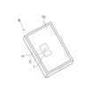
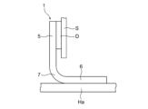
- FIG. FIG. 2 is a schematic diagram showing an example of the vapor chamber according to the first embodiment mounted on the electronic device shown in FIG. 1.
- FIG. FIG. 3 is a schematic diagram showing another example of the vapor chamber according to the first embodiment mounted on the electronic device shown in FIG.
- FIG. 4 is an external perspective view showing the vapor chamber according to the first embodiment.
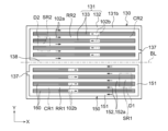
- 5 is a plan view of the vapor chamber shown in FIG. 2 before bending;
- FIG. 6 is a cross-sectional view taken along the line AA of FIG. 5.
- FIG. 7 is a plan view showing the inner surface of the first sheet shown in FIG. 6.
- FIG. 8 is a plan view showing the inner surface of the second sheet shown in FIG. 6.
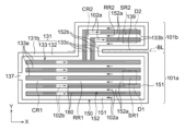
- FIG. 9 is a plan view showing the first main body surface of the wick sheet shown in FIG. 6.
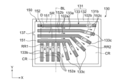
- FIG. 10 is a plan view showing the second main body surface of the wick sheet shown in FIG. 6.
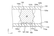
- FIG. 11 is a partially enlarged cross-sectional view of FIG. 6, which is a cross-sectional view taken along the line BB of FIG. 13, which will be described later.
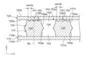
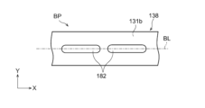
- FIG. 12 is a partially enlarged view of the liquid flow path shown in FIG. 9.
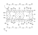
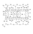
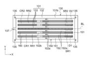
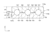
- FIG. 13 is a schematic diagram showing the outer surface of the seat in the bending region of the vapor chamber shown in FIG. 4;
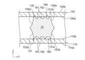
- FIG. 14 is a cross-sectional view taken along line CC of FIG. 13.
- 15 is a cross-sectional view showing a modified example of the vapor chamber according to the first embodiment, and is a cross-sectional view at an end portion in the width direction of the vapor chamber.
- 16 is a cross-sectional view showing a modification of the vapor chamber shown in FIG. 14.
- FIG. 17 is a cross-sectional view showing a modification of the vapor chamber shown in FIG. 14.
- FIG. 18 is a cross-sectional view showing a modification of the vapor chamber shown in FIG. 14.
- FIG. 19 is a cross-sectional view showing a modification of the vapor chamber shown in FIG. 14.
- FIG. 20 is a cross-sectional view showing a modification of the vapor chamber shown in FIG. 14.
- FIG. 21 is a cross-sectional view showing a modification of the vapor chamber shown in FIG. 14.
- FIG. 22 is a cross-sectional view showing a modification of the vapor chamber shown in FIG. 14.
- FIG. 23 is a cross-sectional view showing a modification of the vapor chamber shown in FIG. 14.
- FIG. 24 is a plan view showing a modified example of the vapor chamber according to the first embodiment, and is a plan view showing an enlarged liquid flow path portion.
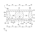
- 25 is a cross-sectional view of the first and second regions of the vapor chamber shown in FIG. 24.
- FIG. 25 is a cross-sectional view of the bend region of the vapor chamber shown in FIG. 24; FIG. FIG.
- FIG. 27 is a plan view showing a modified example of the vapor chamber according to the first embodiment, and is a plan view showing an enlarged second main body surface of the land portion.
- 28 is a plan view showing another example of FIG. 27.
- FIG. 29 is a cross-sectional view showing a modification of the vapor chamber shown in FIG. 13.
- FIG. 30 is an external perspective view showing the vapor chamber according to the second embodiment.
- 31 is a plan view showing the vapor passage in which the bend region in the vapor chamber shown in FIG. 30 is expanded.
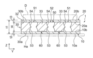
- 32 is a schematic cross-sectional view showing the steam passage along lines DD, EE, and FF of FIG. 31.
- FIG. 33 is a plan view showing a modification of the vapor chamber shown in FIG. 30 before bending;
- FIG. 34 is a plan view showing the contour of the vapor chamber before bending according to the third embodiment.
- 35 is a plan view showing a modification of the vapor chamber shown in FIG. 34.
- FIG. 36 is a plan view showing another modification of the vapor chamber shown in FIG. 34.
- FIG. 37 is a plan view showing another modification of the vapor chamber shown in FIG. 24.
- FIG. FIG. 38 is a perspective view showing a bent vapor chamber according to a fourth embodiment; 39 is a cross-sectional view taken along the line AA-AA of FIG. 38.
- FIG. 40 is a diagram for explaining the vapor chamber of FIG. 38, and is a plan view showing the vapor chamber in an unbent state.
- FIG. 41 is a cross-sectional view taken along line BB-BB of FIG.
- FIG. 42 is a plan view showing the inner surface of the first sheet of FIG. 41.
- FIG. 43 is a plan view showing the inner surface of the second sheet of FIG. 41.
- FIG. 44 is a plan view showing the second body surface of the body sheet of FIG. 41.
- FIG. 45 is a partially enlarged sectional view of FIG. 41.
- FIG. 46 is a partially enlarged view of the liquid flow path shown in FIG. 45.
- FIG. FIG. 47 is a diagram for explaining a material sheet preparation step in the vapor chamber manufacturing method according to the fourth embodiment.
- FIG. 48 is a diagram for explaining an etching step in the vapor chamber manufacturing method according to the fourth embodiment.
- FIG. 49 is a diagram for explaining a bonding step in the vapor chamber manufacturing method according to the fourth embodiment.
- FIG. 50 is a diagram for explaining a bending step in the vapor chamber manufacturing method according to the fourth embodiment.
- FIG. 51 is a cross-sectional view showing a modified example of the vapor chamber shown in FIG. 45, and is a cross-sectional view showing an enlarged liquid flow path portion.
- FIG. 52 is a cross-sectional view showing a modified example of the vapor chamber shown in FIG. 45, and is a cross-sectional view showing an enlarged liquid flow path portion.
- 53 is a cross-sectional view showing a modification of the vapor chamber shown in FIG. 45.
- FIG. 54 is a cross-sectional view showing a modification of the vapor chamber shown in FIG. 45.
- FIG. 55 is a cross-sectional view showing a modification of the vapor chamber shown in FIG. 45.
- FIG. 56 is a cross-sectional view showing a modification of the vapor chamber shown in FIG. 45.
- FIG. 57 is a plan view showing a modification of the vapor chamber shown in FIG. 44.
- FIG. FIG. 58 is a cross-sectional view showing a modified example of the vapor chamber shown in FIG. 57, and is a cross-sectional view showing an enlarged liquid flow path portion.
- FIG. 59 is a cross-sectional view showing a modified example of the vapor chamber shown in FIG. 57, and is a cross-sectional view showing an enlarged liquid flow path portion.
- FIG. 60 is a cross-sectional view showing a modified example of the vapor chamber shown in FIG. 57, and is a cross-sectional view showing an enlarged liquid flow path portion.
- FIG. 61 is a plan view showing a modified example of the vapor chamber shown in FIG. 57, and is a plan view showing an enlarged liquid flow path portion.
- FIG. FIG. 62 is a cross-sectional view showing a modified example of the vapor chamber shown in FIG. 57, and is a cross-sectional view showing an enlarged liquid flow path portion.
- 63 is a plan view showing a modification of the vapor chamber shown in FIG. 44.
- FIG. 64 is a plan view showing a modification of the vapor chamber shown in FIG. 63.
- FIG. 65 is a plan view showing a modification of the vapor chamber shown in FIG. 63.
- FIG. 66 is a plan view showing a modification of the vapor chamber shown in FIG. 65.
- FIG. 67 is a plan view showing a modified example of the vapor chamber shown in FIG. 65, and is a plan view showing an enlarged reinforcement portion.
- FIG. 68 is a plan view showing another example of FIG. 67.
- FIG. 69 is a plan view showing a modification of the vapor chamber shown in FIG. 65.
- FIG. 70 is an enlarged plan view showing a modification of the vapor chamber shown in FIG. 65, and is an enlarged plan view showing the first main body surface of the land portion.
- FIG. 71 is a plan view showing a modification of the vapor chamber shown in FIG. 63.
- FIG. 72 is a plan view showing a modification of the vapor chamber shown in FIG. 44.
- FIG. 73 is a plan view showing a modification of the vapor chamber shown in FIG.
- FIG. 74 is a plan view showing a modification of the vapor chamber shown in FIG. 73.
- FIG. 75 is a plan view showing a modification of the vapor chamber shown in FIG. 44.
- FIG. 76 is a cross-sectional view showing a modification of the vapor chamber shown in FIG. 39.
- FIG. 77 is a cross-sectional view at a bend of the vapor chamber shown in FIG. 76;
- FIG. 78 is a cross-sectional view showing a modification of the vapor chamber shown in FIG. 76.
- FIG. 79 is a cross-sectional view showing a modification of the vapor chamber shown in FIG. 41.
- FIG. 80 is a sectional view showing another example of FIG. 79.
- FIG. 79 is a sectional view showing another example of FIG. 79.
- Geometric conditions, physical properties, terms specifying the degree of geometric conditions or physical properties, numerical values indicating geometric conditions or physical properties, etc. used in this specification are strictly You can interpret without being bound by the meaning. These geometric conditions, physical characteristics, terms, numerical values, and the like may be interpreted to include the extent to which similar functions can be expected. Examples of terms specifying geometric conditions include “length”, “angle”, “shape” and “disposition”. Examples of terms specifying geometric conditions include “parallel,” “orthogonal,” and “identical.” Furthermore, to clarify the drawings, the shapes of parts that can be expected to have similar functions are described regularly. However, without being bound by a strict meaning, the shapes of the portions may differ from each other within the range in which the functions can be expected. In the drawings, the boundary lines indicating the joint surfaces of the members are shown as simple straight lines for convenience, but they are not bound to be strictly straight lines, and within the range where the desired joint performance can be expected, The shape of the boundary line is arbitrary.
- FIG. 1 A vapor chamber, an electronic device, and a vapor chamber manufacturing method according to a first embodiment of the present disclosure will be described with reference to FIGS. 1 to 29.
- FIG. The vapor chamber 1 according to the present embodiment is housed in a housing H of an electronic device E together with an electronic device D that generates heat, and is a device for cooling the electronic device D.
- Examples of the electronic device E include mobile terminals such as portable terminals and tablet terminals.
- Examples of electronic devices D include central processing units (CPUs), light emitting diodes (LEDs), power semiconductors, and the like.
- Electronic device D may also be referred to as a cooled device.
- the electronic equipment E may include a housing H, an electronic device D housed within the housing H, and a vapor chamber 1 .
- a touch panel display TD is provided on the front surface of the housing H.
- the vapor chamber 1 is housed within the housing H and arranged to be in thermal contact with the electronic device D. As shown in FIG. The vapor chamber 1 receives heat generated by the electronic device D when the electronic equipment E is used.
- the heat received by the vapor chamber 1 is released to the outside of the vapor chamber 1 via working fluids 2a and 2b, which will be described later, and the electronic device D is effectively cooled. If the electronic device E is a tablet terminal, the electronic device D corresponds to a central processing unit or the like.
- the vapor chamber 1 according to this embodiment is bent as shown in FIGS.
- the vapor chamber 1 is bent according to the internal structure of the electronic equipment E. As shown in FIG. Depending on the positional relationship between the heat-generating electronic device E and the heat-dissipating housing member Ha, the vapor chamber 1 may be bent.
- the housing member Ha is a member that constitutes the housing H. As shown in FIG.
- FIG. 1 An example is the case where the electronic device D and the housing member Ha are arranged as shown in FIG. In this case, the vapor chamber 1 is bent at right angles so as to contact the electronic device D and the housing member Ha. Electronic device D is mounted on substrate S. As shown in FIG. Another example is the case where the electronic device D and the housing member Ha are arranged as shown in FIG. In this case, the vapor chamber 1 is bent 180 degrees so as to contact the electronic device D and the housing member Ha.
- FIGS. 2 and 3 show an example of the vapor chamber 1 bent at one bend line 8 (see FIGS. 4 and 5), but this is not limiting. The vapor chamber 1 may be bent at two or more bend lines 8 at different positions.
- the vapor chamber 1 that is bent at right angles along one bending line 8 will be described as an example.
- the vapor chamber 1 shown in FIG. 4 is divided into a first region 5 , a second region 6 and a bend region 7 located between the first region 5 and the second region 6 .
- the vapor chamber 1 is bent at right angles.
- the first region 5 and the second region 6 are formed substantially flat.
- the first region 5 may be in contact with the electronic device D, and the second region 6 may be in contact with the housing member Ha (see FIG. 2).
- FIGS. 5 to 11 showing the vapor chamber 1 before being bent.
- the vapor chamber 1 has a sealed space 3 filled with working fluids 2a and 2b.
- working fluids 2a and 2b include pure water, ethanol, methanol, acetone, etc., and mixtures thereof.
- the vapor chamber 1 includes a first sheet 10, a second sheet 20, a wick sheet 30, a vapor channel portion 50, and a first liquid channel portion 60. ing.
- the second sheet 20 is provided on the side opposite to the first sheet 10 with respect to the wick sheet 30 .
- the wick sheet 30 is an example of a main sheet and is interposed between the first sheet 10 and the second sheet 20 .
- the first sheet 10, the wick sheet 30 and the second sheet 20 are stacked in this order.
- an example in which one wick sheet 30 is stacked will be described, but two or more wick sheets 30 may be stacked.
- the vapor chamber 1 shown in FIG. 5 is generally formed in the shape of a thin flat plate.
- the vapor chamber 1 may have any planar shape before bending, it may have a rectangular shape as shown in FIG.
- the planar shape of the vapor chamber 1 may be, for example, a rectangle with one side of 1 cm and the other side of 3 cm, or a square with one side of 15 cm.
- the plane dimensions of the vapor chamber 1 before bending are arbitrary. In the present embodiment, an example will be described in which the planar shape of the vapor chamber 1 before bending is a rectangular shape whose longitudinal direction is the X direction, which will be described later.
- the first sheet 10, the second sheet 20 and the wick sheet 30 may have the same planar shape as the vapor chamber 1, as shown in FIGS.
- the planar shape of the vapor chamber 1 before bending is not limited to a rectangular shape, and may be any shape such as a circular shape, an elliptical shape, an L-shape, or a T-shape.
- the vapor chamber 1 has an evaporation area SR where the working fluid 2b evaporates and a condensation area CR where the working steam 2a condenses.
- the working vapor 2a is a gaseous working fluid
- the working liquid 2b is a liquid working fluid.
- the evaporation region SR is a region that overlaps with the electronic device D in plan view, and is a region that contacts the electronic device D. Although the evaporation area SR is located within the first area 5, the location of the evaporation area SR is arbitrary. In the present embodiment, an evaporation region SR is formed on one side (left side in FIG. 5) of the vapor chamber 1 in the X direction. Heat from the electronic device D is transferred to the evaporation region SR, and the heat evaporates the working liquid 2b to generate the working vapor 2a. The heat from the electronic device D can be transmitted not only to the area overlapping the electronic device D in plan view, but also to the periphery of the area overlapping the electronic device D. Therefore, the evaporation region SR may include a region overlapping the electronic device D and a region therearound in plan view.
- the condensation area CR is an area that does not overlap the electronic device D in plan view, and is an area where the working steam 2a mainly releases heat and condenses.
- the condensation area CR may be located within the second area 6 .
- the condensation region CR may be a region surrounding the evaporation region SR including the second region 6 . Heat is released from the working steam 2a in the condensation region CR.
- the working steam 2a is cooled and condensed to produce a working fluid 2b.
- planar view means a state in which the vapor chamber 1 is viewed from a direction orthogonal to the surface receiving heat from the electronic device D and the surface emitting the received heat.
- the surface that receives heat corresponds to a second sheet outer surface 20b of the second sheet 20, which will be described later.
- the surface that emits heat corresponds to a first sheet outer surface 10a of the first sheet 10, which will be described later.
- FIG. 4 in the bent first region 5 of the vapor chamber 1, the state viewed in the direction indicated by the arrow V1 corresponds to a planar view. In the second region 6, the state viewed in the direction indicated by the arrow V2 corresponds to a planar view.
- the vapor chamber 1 before bending corresponds to a plan view when the vapor chamber 1 is viewed from above or from below.
- the first sheet 10 includes a first sheet outer surface 10a positioned opposite to the wick sheet 30 and a first sheet inner surface 10b facing the wick sheet 30. As shown in FIG. In the second region 6 described above, the housing member Ha described above contacts the first seat outer surface 10a. A first body surface 30a of the wick sheet 30, which will be described later, is in contact with the first sheet inner surface 10b. As shown in FIGS. 6 and 7, the first sheet 10 may be formed substantially flat. The first sheet 10 may have a substantially constant thickness.
- alignment holes 12 may be formed in the four corners of the first sheet 10 .
- FIG. 7 shows an example in which the planar shape of the alignment hole 12 is circular, it is not limited to this.
- the alignment holes 12 may penetrate the first sheet 10 .
- the second sheet 20 includes a second sheet inner surface 20 a facing the wick sheet 30 and a second sheet outer surface 20 b located on the opposite side of the wick sheet 30 .
- the electronic device D described above contacts the second sheet outer surface 20b.
- a later-described second body surface 30b of the wick sheet 30 is in contact with the second sheet inner surface 20a.
- the second sheet 20 may be formed substantially flat.
- the second sheet 20 may have a substantially constant thickness.
- alignment holes 22 may be formed in the four corners of the second sheet 20 .
- FIG. 8 shows an example in which the planar shape of the alignment hole 22 is circular, it is not limited to this.
- the alignment holes 22 may pass through the second sheet 20 .
- the wick sheet 30 has a first main body surface 30a and a second main body surface 30b opposite to the first main body surface 30a.
- the first sheet inner surface 10b of the first sheet 10 is in contact with the first body surface 30a.
- the second sheet inner surface 20a of the second sheet 20 is in contact with the second body surface 30b.
- the first sheet inner surface 10b of the first sheet 10 and the first body surface 30a of the wick sheet 30 may be diffusion-bonded.
- the first seat inner surface 10b and the first body surface 30a may be permanently joined together.
- the second sheet inner surface 20a of the second sheet 20 and the second body surface 30b of the wick sheet 30 may be diffusion bonded.
- the second seat inner surface 20a and the second body surface 30b may be permanently joined together.
- the wick sheet 30 includes a frame portion 32 and a plurality of first lands 33.
- the frame body portion 32 defines the steam channel portion 50 and is formed in a rectangular frame shape along the X direction and the Y direction in plan view.
- the first land portion 33 is located inside the steam channel portion 50 and is located inside the frame portion 32 in plan view.
- the frame portion 32 and the first land portion 33 are portions where the material of the wick sheet 30 remains without being etched in the etching process described later.
- a first steam passage 51 which will be described later, through which the working steam 2a flows is formed.
- a second steam passage 52 (to be described later) through which the working steam 2a flows is formed between the first land portions 33 adjacent to each other.
- the first land portion 33 may extend in an elongated shape with the X direction as its longitudinal direction in plan view.
- the planar shape of the first land portion 33 may be an elongated rectangular shape.
- the X direction is an example of a first direction and corresponds to the horizontal direction in FIGS. 9 and 10.
- FIG. also, the first land portions 33 may be arranged at regular intervals in the Y direction.
- the Y direction is an example of a second direction, and is a direction orthogonal to the X direction in plan view.
- the Y direction corresponds to the vertical direction in FIGS. 9 and 10.
- Each first land portion 33 may be positioned parallel to each other.
- a direction orthogonal to each of the X direction and the Y direction is defined as the Z direction.
- the Z direction corresponds to the vertical direction in FIGS. 6 and 11, and corresponds to the thickness direction.
- the width w1 of the first land portion 33 may be, for example, 100 ⁇ m to 1500 ⁇ m.
- the width w1 of the first land portion 33 is the dimension of the first land portion 33 in the Y direction.
- the width w1 means the dimension of the wick sheet 30 in the Z direction at the position where the through portion 34, which will be described later, exists.
- the X direction in the first region 5 and the second region 6 of the vapor chamber 1 shown in FIG. 4 corresponds to the direction along the longitudinal direction of the first land portion 33 .
- the X direction in the first region 5 corresponds to the vertical direction in FIG.
- the Y direction in the first region 5 and the second region 6 of the vapor chamber 1 shown in FIG. 4 corresponds to the direction in which the first land portions 33 are arranged.
- the Z direction corresponds to the direction orthogonal to the vapor chamber 1 in the first region 5 and the second region 6 of the vapor chamber 1 shown in FIG.
- the Z direction in the second area 6 corresponds to the vertical direction in FIG.
- the frame body part 32 and each first land part 33 are diffusion-bonded to the first sheet 10 and diffusion-bonded to the second sheet 20 . This improves the mechanical strength of the vapor chamber 1 .
- a wall surface 53 a of the first steam flow channel recess 53 and a wall surface 54 a of the second steam flow channel recess 54 which will be described later, constitute side walls of the first land portion 33 .
- the first main body surface 30a and the second main body surface 30b of the wick sheet 30 may be formed flat over the frame portion 32 and the respective first land portions 33 .
- alignment holes 35 may be formed at the four corners of the wick sheet 30 .
- 9 and 10 show an example in which the planar shape of the alignment hole 35 is circular, but it is not limited to this. Also, the alignment hole 35 may pass through the wick sheet 30 .
- the steam channel portion 50 may be provided on the first body surface 30a of the wick sheet 30.
- the steam channel portion 50 is an example of a space portion.
- the steam channel portion 50 may be a channel through which the working steam 2a mainly passes.
- the working fluid 2b may also pass through the vapor flow path portion 50 .
- the steam channel portion 50 may extend from the first main body surface 30 a to the second main body surface 30 b or penetrate the wick sheet 30 .
- the steam channel portion 50 may be covered with the first sheet 10 on the first main body surface 30a, and may be covered with the second sheet 20 on the second main body surface 30b.
- the steam flow passage section 50 may include a first steam passage 51 and a plurality of second steam passages 52.
- the first steam passage 51 is formed between the frame portion 32 and the first land portion 33 .
- the first steam passage 51 is an example of a space periphery.
- the first steam passage 51 is formed continuously inside the frame portion 32 and outside the first land portion 33 .
- the planar shape of the first steam passage 51 may be a rectangular frame shape along the X direction and the Y direction.
- the second steam passage 52 is formed between the first lands 33 adjacent to each other.
- the planar shape of the second steam passage 52 may be an elongated rectangular shape.
- the plurality of first lands 33 partition the steam flow path section 50 into a first steam passage 51 and a plurality of second steam passages 52 .
- the first steam passage 51 and the second steam passage 52 may extend from the first body surface 30a of the wick sheet 30 to the second body surface 30b.
- the first steam passage 51 and the second steam passage 52 are defined by a first steam passage recess 53 provided in the first main body surface 30a and a second steam passage recess 54 provided in the second main body surface 30b. contains.
- the first steam channel recess 53 and the second steam channel recess 54 communicate with each other.
- the first steam flow path concave portion 53 may be formed by etching from the first main body surface 30a of the wick sheet 30 in an etching process to be described later.
- the first steam channel recess 53 is formed in a recessed shape on the first body surface 30a.
- the first steam flow channel recess 53 may have a curved wall surface 53a.
- FIG. 11 shows a cross section perpendicular to the X direction. This wall surface 53a defines the first steam flow path recess 53, and may be curved so as to approach the opposing wall surface 53a as it approaches the second body surface 30b.
- the first steam passage concave portion 53 constitutes a portion of the first steam passage 51 relatively close to the first sheet 10 and a portion of the second steam passage 52 relatively close to the first sheet 10 .
- the width w2 of the first steam channel recess 53 may be, for example, 100 ⁇ m to 5000 ⁇ m.
- the width w2 of the first steam flow path recess 53 is the dimension in the Y direction, which is the dimension of the first steam flow path recess 53 on the first main body surface 30a.
- the width w2 corresponds to the Y-direction dimension of the portion of the first steam passage 51 extending in the X direction and the Y-direction dimension of the second steam passage 52 .
- the width w2 also corresponds to the X-direction dimension of the portion of the first steam passage 51 that extends in the Y-direction.
- the second steam flow path concave portion 54 may be formed by etching from the second main body surface 30b of the wick sheet 30 in an etching process described later.
- the second steam flow channel recessed portion 54 is formed in a recessed shape in the second main body surface 30b.
- the second steam flow path concave portion 54 may have a curved wall surface 54a. This wall surface 54a defines the second steam flow path recess 54 and may curve toward the opposing wall surface 54a as it approaches the first body surface 30a.
- the second steam passage concave portion 54 constitutes a portion of the first steam passage 51 relatively close to the second seat 20 and a portion of the second steam passage 52 relatively close to the second seat 20 .
- the width w3 of the second steam channel recess 54 may be, for example, 100 ⁇ m to 5000 ⁇ m, similar to the width w2 of the first steam channel recess 53 described above.
- the width w3 of the second steam flow channel recess 54 is the dimension in the Y direction, which is the dimension of the second steam flow channel recess 54 on the second main body surface 30b.
- the width w3 corresponds to the Y-direction dimension of the portion of the first steam passage 51 extending in the X direction and the Y-direction dimension of the second steam passage 52 .
- the width w3 also corresponds to the X-direction dimension of the portion of the first steam passage 51 that extends in the Y-direction.
- the width w3 of the second steam channel recess 54 may be equal to or different from the width w2 of the first steam channel recess 53 .
- the wall surface 53a of the first steam flow channel recess 53 and the wall surface 54a of the second steam flow channel recess 54 may be connected to form the through portion 34.
- the planar shape of the penetrating portion 34 in the first steam passage 51 may be a rectangular frame shape.
- the planar shape of the penetrating portion 34 in the second steam passage 52 may be an elongated rectangular shape.
- the through portion 34 may be defined by a ridgeline where the wall surface 53a of the first steam flow path recess 53 and the wall surface 54a of the second steam flow path recess 54 merge.
- the ridge line may be formed so as to protrude inside the steam passages 51 and 52 as shown in FIG. 11 .
- the plane area of the first steam passage 51 in the penetration portion 34 may be the minimum, and the plane area of the second steam passage 52 in the penetration portion 34 may be the minimum.
- the width w4 of the penetration portion 34 of each steam passage 51, 52 may be, for example, 400 ⁇ m to 5000 ⁇ m.
- the width w4 of the penetrating portion 34 corresponds to the gap between the first land portions 33 adjacent to each other in the Y direction.
- the position of the penetrating portion 34 in the Z direction may be an intermediate position between the first main body surface 30a and the second main body surface 30b.
- the position of the penetrating portion 34 may be a position closer to the first seat 10 than the intermediate position, or a position closer to the second seat 20 than the intermediate position.
- the position of the penetrating portion 34 in the Z direction is arbitrary.
- the cross-sectional shapes of the first steam passage 51 and the second steam passage 52 are formed so as to include the penetrating portion 34 defined by the ridgeline formed to protrude inward.
- the cross-sectional shape of the first steam passage 51 and the cross-sectional shape of the second steam passage 52 may be trapezoidal, parallelogram-shaped, or barrel-shaped.
- the steam passage portion 50 including the first steam passage 51 and the second steam passage 52 configured in this manner constitutes part of the sealed space 3 described above.
- Each of the steam passages 51, 52 has a relatively large channel cross-sectional area through which the working steam 2a passes.
- FIG. 11 shows the first steam passage 51 and the second steam passage 52 in an enlarged manner for clarity of the drawing.
- the number and positions of the steam passages 51, 52, etc. are different from those in FIGS.
- a plurality of support portions that support the first land portion 33 to the frame portion 32 may be provided in each of the steam passages 51 and 52 .
- a support portion may be provided to support the first land portions 33 adjacent to each other. These support portions may be provided on both sides of the first land portion 33 in the X direction, or may be provided on both sides of the first land portion 33 in the Y direction.
- the support portion is preferably formed so as not to block the flow of the working steam 2a that diffuses through the steam channel portion 50. As shown in FIG. For example, the support portion is positioned near one of the first main body surface 30a and the second main body surface 30b of the wick sheet 30, and a space forming the steam channel portion 50 is formed at a position near the other. may be As a result, the thickness of the supporting portion can be made thinner than the thickness of the wick sheet 30, and the first steam passage 51 and the second steam passage 52 can be prevented from being divided in the X direction and the Y direction.
- the vapor chamber 1 may include an injection part 4 for injecting the working fluid 2b into the sealed space 3.
- the injection section 4 includes an injection passage 36 communicating with the first steam passage 51 .
- the position of the injection part 4 is arbitrary.
- the injection channel 36 may be recessed in the second body surface 30b.
- the injection channel 36 may be recessed in the first body surface 30a.
- the injection channel 36 may communicate with the first liquid channel portion 60 depending on the configuration of the first liquid channel portion 60 .
- the first liquid flow path portion 60 may be formed between the first sheet 10 and the wick sheet 30. As shown in FIGS. In this embodiment, the first liquid flow path portion 60 is formed on the first body surface 30 a of the first land portion 33 .
- the first liquid flow path portion 60 may be a flow path through which the working fluid 2b mainly passes.
- the working steam 2 a described above may pass through the first liquid flow path portion 60 .
- the first liquid channel portion 60 forms part of the sealed space 3 described above and communicates with the vapor channel portion 50 .
- the first liquid flow path section 60 is configured as a capillary structure for transporting the working liquid 2b to the evaporation region SR.
- the first liquid flow path section 60 may also be referred to as a wick.
- the first liquid flow path portion 60 may be formed over the entire first body surface 30 a of each first land portion 33 . Although not shown in FIG. 9 and the like, the first liquid flow path portion 60 may be formed in the inner portion of the first main body surface 30a of the frame portion 32 . In the present embodiment, the first liquid flow path portion 60 is not formed on the second main body surface 30b of the first land portion 33 and the second main body surface 30b of the frame portion 32 .
- the first liquid flow path portion 60 is an example of a first groove aggregate including a plurality of grooves. More specifically, the first liquid flow path portion 60 includes multiple mainstream grooves 61 and multiple communication grooves 65 .
- the main groove 61 and the communication groove 65 are grooves through which the hydraulic fluid 2b passes.
- the communication groove 65 communicates with the main groove 61 .
- Each mainstream groove 61 extends in the X direction, as shown in FIG.
- the main groove 61 mainly has a small flow cross-sectional area so that the working fluid 2b flows by capillary action.
- the channel cross-sectional area of the main groove 61 is smaller than the channel cross-sectional areas of the steam passages 51 and 52 .
- the main groove 61 is configured to transport the working fluid 2b condensed from the working steam 2a to the evaporation region SR.
- Each main groove 61 may be spaced apart at equal intervals along the Y direction orthogonal to the X direction.
- Each mainstream groove 61 may be positioned parallel to each other.
- the main groove 61 is formed by etching from the first main body surface 30a of the wick sheet 30 in an etching process to be described later. Accordingly, the main groove 61 may have a curved wall surface 62 as shown in FIG.
- the wall surface 62 defines the mainstream groove 61 and may be curved in a shape that bulges toward the second body surface 30b.
- the width w5 of the main groove 61 may be smaller than the width w2 of the first steam flow passage recess 53.
- the width w ⁇ b>5 of the main groove 61 may be smaller than the width w ⁇ b>1 of the first land portion 33 .
- the width w5 of the main groove 61 may be, for example, 5 ⁇ m to 400 ⁇ m.
- the width w5 means the dimension of the main groove 61 on the first main body surface 30a. 11 and 12, the width w5 corresponds to the Y-direction dimension of the main groove 61.
- the depth h1 of the main groove 61 may be, for example, 3 ⁇ m to 300 ⁇ m.
- the depth h1 corresponds to the Z-direction dimension of the main groove 61 .
- each communication groove 65 extends in a direction different from the X direction.
- each communication groove 65 extends in the Y direction and is formed perpendicular to the main groove 61 .
- Some communication grooves 65 communicate with adjacent main grooves 61 .
- Another communication groove 65 communicates the first steam passage 51 or the second steam passage 52 with the main groove 61 . That is, the communication groove 65 extends from the side edge 33a of the first land portion 33 in the Y direction to the main groove 61 adjacent to the side edge 33a. In this manner, the first steam passage 51 communicates with the main groove 61 and the second steam passage 52 communicates with the main groove 61 .
- the communication groove 65 has a small channel cross-sectional area so that the working fluid 2b mainly flows by capillary action.
- the channel cross-sectional area of the communication groove 65 is smaller than the channel cross-sectional areas of the steam passages 51 and 52 .
- the communication grooves 65 are evenly spaced along the X direction. Each communication groove 65 may be positioned parallel to each other.
- the communication groove 65 is also formed by etching, which will be described later, similarly to the main groove 61 . Accordingly, the communication groove 65 may have a curved wall surface (not shown) similar to that of the main groove 61 .
- a width w ⁇ b>6 of the communication groove 65 may be smaller than a width w ⁇ b>2 of the first steam flow path concave portion 53 .
- Width w ⁇ b>6 of communication groove 65 may be smaller than width w ⁇ b>1 of first land portion 33 .
- the width w6 of the communication groove 65 may be equal to the width w5 of the main groove 61 . However, width w6 may be larger or smaller than width w5.
- the width w6 means the dimension of the communication groove 65 in the first main body surface 30a. In FIG. 12, the width w6 corresponds to the dimension of the communication groove 65 in the X direction.
- the depth of the communication groove 65 may be equal to the depth h1 of the main groove 61 . However, the depth of the communication groove 65 may be deeper or shallower than the depth h1.
- the first liquid flow path section 60 has a row of protrusions 63 .
- the row of protrusions 63 is provided on the first main body surface 30 a of the wick sheet 30 .
- the row of protrusions 63 is provided between the main grooves 61 adjacent to each other.
- Each projection row 63 includes a plurality of projections 64 arranged in the X direction.
- the convex portion 64 is in contact with the first sheet 10 .
- each convex portion 64 is formed in a rectangular shape so that the X direction is the longitudinal direction in plan view.
- Main grooves 61 are interposed between protrusions 64 adjacent to each other in the Y direction.
- a communication groove 65 is interposed between the protrusions 64 adjacent to each other in the X direction.
- the convex portion 64 is a portion where the material of the wick sheet 30 remains without being etched in the etching process described later.
- the planar shape of the convex portion 64 is rectangular. More specifically, the planar shape of the convex portion 64 corresponds to the planar shape at the position of the first main body surface 30a.
- the protrusions 64 are arranged in a zigzag pattern. More specifically, the convex portions 64 of the convex portion rows 63 adjacent to each other in the Y direction are positioned at positions shifted from each other in the X direction. This shift amount may be half the arrangement pitch of the protrusions 64 in the X direction.
- the width w7 of the protrusion 64 may be, for example, 5 ⁇ m to 500 ⁇ m.
- the width w7 means the dimension of the projection 64 on the first main body surface 30a. In FIG. 12, the width w7 corresponds to the Y-direction dimension of the projection 64.
- the positions of the protrusions 64 are not limited to being staggered, and may be arranged in parallel. In this case, the convex portions 64 of the convex portion rows 63 adjacent to each other in the Y direction are positioned at the same position in the X direction.
- each sheet 10, 20, 30 may be composed of a metallic material.
- each sheet 10, 20, 30 may comprise copper or a copper alloy. Copper and copper alloys have good thermal conductivity and corrosion resistance when using pure water as the working fluid. Examples of copper include pure copper and oxygen-free copper (C1020). Examples of copper alloys include copper alloys containing tin, copper alloys containing titanium (such as C1990), and Corson copper alloys (such as C7025), which are copper alloys containing nickel, silicon and magnesium.
- a copper alloy containing tin is, for example, phosphor bronze (C5210 or the like).
- the materials forming the first sheet 10, the second sheet 20 and the wick sheet 30 are not particularly limited as long as they have good thermal conductivity.
- Each sheet 10, 20, 30 may comprise copper or a copper alloy, for example.
- the thermal conductivity of each sheet 10, 20, 30 can be increased, and the heat dissipation efficiency of the vapor chamber 1 can be increased.
- corrosion can be prevented.
- These sheets 10, 20, 30 may be made of other metal materials such as aluminum or titanium, or other metal alloy materials such as stainless steel, as long as the desired heat radiation efficiency can be obtained and corrosion can be prevented.
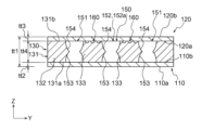
- the thickness t1 of the vapor chamber 1 shown in FIG. 5 may be, for example, 100 ⁇ m to 500 ⁇ m.
- the thickness t1 of the vapor chamber 1 may be, for example, 100 ⁇ m to 500 ⁇ m.
- the vapor passage portion 50 can be properly secured. Therefore, the vapor chamber 1 can function properly.
- the thickness t1 to 500 ⁇ m or less it is possible to suppress the thickness t1 of the vapor chamber 1 from increasing. Therefore, the vapor chamber 1 can be made thin.
- the thickness of the wick sheet 30 may be thicker than the thickness of the first sheet 10 .
- the thickness of the wick sheet 30 may be thicker than the thickness of the second sheet 20 .
- This embodiment shows an example in which the thickness of the first sheet 10 and the thickness of the second sheet 20 are equal. However, it is not limited to this, and the thickness of the first sheet 10 and the thickness of the second sheet 20 may be different.
- the thickness t2 of the first sheet 10 may be, for example, 6 ⁇ m to 100 ⁇ m. By setting the thickness t2 of the first sheet 10 to 6 ⁇ m or more, the mechanical strength and long-term reliability of the first sheet 10 can be ensured. On the other hand, by setting the thickness t2 of the first sheet 10 to 100 ⁇ m or less, it is possible to suppress the thickness t1 of the vapor chamber 1 from increasing.
- the thickness t3 of the second sheet 20 may be set similarly to the thickness t2 of the first sheet 10 .
- the thickness t4 of the wick sheet 30 may be, for example, 50 ⁇ m to 400 ⁇ m. By setting the thickness t4 of the wick sheet 30 to 50 ⁇ m or more, the vapor passage portion 50 can be appropriately secured. Therefore, the vapor chamber 1 can function properly. On the other hand, by setting the thickness to 400 ⁇ m or less, it is possible to suppress the thickness t1 of the vapor chamber 1 from increasing. Therefore, the vapor chamber 1 can be made thin.
- the thickness t4 of the wick sheet 30 may be the distance between the first main body surface 30a and the second main body surface 30b.
- the vapor chamber 1 is divided into the first region 5, the second region 6, and the bending region 7.
- the vapor chamber 1 bends along a bending line 8 extending in a direction crossing the X direction in plan view.
- the bending line 8 extends in the Y direction in plan view.
- the Y direction is a direction orthogonal to the X direction in plan view.
- the bending line 8 crosses the frame portion 32 , the first land portion 33 , the first steam passage 51 and the second steam passage 52 .
- first sheet 10 can be prevented from being deformed into the steam passages 51 and 52
- second sheet 20 can be prevented from being deformed into the steam passages 51 and 52 .
- the passage cross-sectional areas of the first steam passage 51 and the second steam passage 52 can be secured.
- the first area 5 , the second area 6 and the bending area 7 may be separated by a boundary line along the bending line 8 .
- the regions 5, 6, and 7 may be separated by boundary lines extending in the Y direction in plan view.
- the bending area 7 is an area having a certain width including the bending line 8 .
- the bending region 7 is constituted by a portion where the vapor chamber 1 is deformed by bending.
- the first area 5 and the second area 6 correspond to areas other than the bending area 7 . That is, the first region 5 and the second region 6 are regions that are not bent.
- the first region 5 and the second region 6 may be regions extending on the XY plane without bending.
- the first region 5 and the second region 6 may consist of portions of the curved vapor chamber 1 where no deformation has occurred.
- the first region 5 and the second region 6 may be two regions separated by the bending region 7.
- the first region 5 may be a region located on one side (left side in FIG. 5) of the bending region 7 in the direction perpendicular to the bending line 8 (the X direction in the illustrated example).
- the first region 5 may be a region adjacent to the bending region 7 on one side of the bending region 7 .
- the second region 6 may be a region located on the other side (right side in FIG. 5) of the bending region 7 in the direction orthogonal to the bending line 8 .
- the second region 6 may be a region adjacent to the bending region 7 on the other side of the bending region 7 .
- the first region 5 extends from the boundary line with the bending region 7 to the end of the vapor chamber 1 on one side in the X direction (the left side in FIG. 5), and the second region 6 is It spreads from the boundary line with the bending region 7 to the end of the vapor chamber 1 on the other side in the X direction (the right side in FIG. 5), but is not limited to this.
- the first region 5 may not extend to one end of the vapor chamber 1 in the X direction
- the second region 6 may not extend to the other end of the vapor chamber 1 in the X direction.
- the vapor chamber 1 is bent as shown in FIG. In the bending region 7 , the first sheet 10 is positioned outside the wick sheet 30 with respect to the center O of bending.
- the second sheet 20 is located inside the wick sheet 30 with respect to the center O of bending.
- Each steam passage 51, 52 may include a passage bend 57 located in the bend region 7, as shown in FIG.
- FIG. 13 shows an example of the passage bend 57.
- the shape of the curved passage portion 57 when viewed in the Y direction is a quarter arc, but the shape is not limited to this.
- the passage bent portion 57 may include the first steam flow path recess 53 and the second steam flow path recess 54 described above.
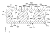
- the first sheet outer surface 10a of the first sheet 10 described above may include a plurality of first bonding regions 13 and first steam channel regions 14. good.
- Each of the first joint regions 13 is a region that overlaps the corresponding first land portion 33 in plan view.
- the first joint region 13 is a portion of the wick sheet 30 joined to the first land portion 33 .
- the first steam channel region 14 is an example of a first spatial region.
- the first steam channel region 14 is a region that overlaps with the steam channel portion 50 in plan view.
- the first steam channel region 14 is a portion that is not joined to the wick sheet 30 .
- a flow channel cross-section of the first steam flow channel region 14 may be formed in a concave shape so as to be recessed inward toward the steam flow channel portion 50 .
- the first steam flow path region 14 may be curved.
- the first steam flow path region 14 of the first sheet outer surface 10a may be formed in a concave shape in each of the first region 5, the second region 6 and the bending region 7. More specifically, in each of the first region 5 and the second region 6, as shown in FIG. 11, the first steam flow path region 14 may be formed in a concave shape. 11 is a cross-sectional view taken along the line BB of FIG. 13. FIG. In the bent region 7, as shown in FIG. 14, the first steam flow path region 14 may be formed in a concave shape. 14 is a cross-sectional view taken along line CC of FIG. 13. FIG. The first steam flow path region 14 may be formed in a concave shape over the entire first sheet outer surface 10a.
- the first sheet 10 may include a first sheet recessed portion 15 overlapping the first steam flow path region 14 in plan view.
- the first seat recess 15 enters the first steam channel recess 53 .
- the portion of the first joint region 13 of the first sheet 10 is joined to the first land portion 33 , so that portion deforms along the first land portion 33 .
- the portion of the first steam channel region 14 of the first sheet 10 covers the steam passages 51 and 52 of the steam channel portion 50 , and thus is less stretchable than the portion of the first joint region 13 . Therefore, the extension of the portion of the first steam flow path region 14 is small.
- the first seat recess 15 is displaced inward and enters the first steam flow path recess 53 .
- the recess dimension of the first steam flow path region 14 in the bent region 7 is larger than the recess dimension of the first steam flow channel region 14 in the first region 5 and the second region 6 .
- the maximum dimension d2 in the bending region 7 is larger than the maximum dimension d1 in the first region 5 and the second region 6 when viewed along the direction parallel to the bending line 8 .
- the maximum dimension d1 is the dimension defined between the first joining region 13 and the first steam channel region 14 in the first region 5 and the second region 6, and is the dimension in the thickness direction of the first sheet 10. is.
- the thickness direction of the first sheet 10 corresponds to the Z direction.
- the maximum dimension d2 is the dimension defined between the first bonding region 13 and the first steam channel region 14 in the bending region 7 and is the dimension in the thickness direction of the first sheet 10 .
- FIG. 13 is a view in a direction parallel to the bending line 8, in other words along the Y direction.
- the maximum dimensions d1 and d2 in the thickness direction of the first sheet 10 defined between the first bonding region 13 and the first steam channel region 14 are defined as the first maximum dimension d3. , d4.
- the maximum dimension d2 in the bending region 7 is larger than the maximum dimension d1 in the first region 5 and the second region 6, it means that the maximum dimension d2 at one position where the bending region 7 is located is the first region 5 and the second region 6, and the maximum dimension d2 at all positions of the bending region 7 is greater than the maximum dimension d1 at all positions of the first region 5 and the second region 6. is not required.
- the first steam flow path area 14 is recessed in each of the first area 5 and the second area 6 .
- the first bonding region 13 is formed flat in each of the X direction and the Y direction.
- the dimension d1 mentioned above may be the depth dimension of the recess.
- the dimension d1 is the distance between the most recessed position in the first steam flow path region 14 and a straight line on the first joint region 13 that overlaps the position and extends in the Y direction when viewed in the normal direction of the position.
- the dimension d1 may be the distance in the Z direction between the most recessed position of the first steam flow path region 14 and the position of the flat portion of the first bonding region 13 .
- Dimension d1 may be obtained from each of first region 5 and second region 6 .
- the dimension d1 in the first region 5 and the dimension d1 in the second region 6 may be equal or different.
- FIG. 14 shows a cross section of the vapor chamber 1 perpendicular to the X direction in the bending region 7.
- the first steam flow path region 14 in the bent region 7 is recessed.
- the first bonding region 13 in the bending region 7 is formed flat in the Y direction.
- the dimension d2 mentioned above may be the depth dimension of the recess.
- the dimension d2 is the distance between the most recessed position in the first steam flow path region 14 and a straight line on the first joint region 13 that overlaps the position and extends in the Y direction when viewed in the normal direction of the position.
- FIG. 14 is a cross-sectional view taken along line CC of FIG. 13, and is a cross-sectional view at a position where the first steam flow path region 14 is most recessed.
- FIG. 14 shows a cross section at a position rotationally displaced by 45° from the boundary between the first region 5 and the bending region 7 with respect to the center O of bending.
- the position where the first steam flow path region 14 is most recessed is not limited to this.
- the first steam channel region 14 shown in FIG. 14 is recessed more than the first steam channel region 14 shown in FIG. Therefore, the dimension d2 is larger than the dimension d1.
- the first sheet recesses 15 in the bent region 7 penetrate into the first steam channel recesses 53 deeper than the first sheet recesses 15 in the first region 5 and the second region 6 .
- flow path corners 55 that form a part of the cross section of the steam flow path by the first sheet inner surface 10 b of the first sheet recess 15 and the wall surface 53 a of the first steam flow path recess 53 . is defined.
- the channel corner portion 55 may be formed in a wedge shape.
- the angle between the first sheet inner surface 10b and the wall surface 53a may be ⁇ 1.
- ⁇ 1 may be an acute angle.
- the angle ⁇ 1 may be defined by a tangent to the first seat inner surface 10b and a tangent to the wall surface 53a at the intersection of the first seat inner surface 10b and the wall surface 53a.
- the angle between the first sheet inner surface 10b and the wall surface 53a may be ⁇ 2.
- ⁇ 2 may be defined similarly to ⁇ 1.
- the angle ⁇ 2 shown in FIG. 14 may be smaller than the angle ⁇ 1 shown in FIG. This is because the first steam channel region 14 shown in FIG. 14 is recessed more than the first steam channel region 14 shown in FIG. 11 . In this case, the capillary action of the channel corner portion 55 shown in FIG. 14 may be stronger than the capillary action of the channel corner portion 55 shown in FIG.
- the first steam flow path region 14 may extend in the X direction in each of the first region 5, the second region 6, and the curved region 7, like the first land portion 33.
- the first sheet concave portion 15 and the channel corner portion 55 may similarly extend in the X direction.
- the second sheet outer surface 20b of the second sheet 20 described above may include a plurality of second bonding regions 23 and second steam channel regions 24. good.
- Each of the second joint regions 23 is a region that overlaps the corresponding first land portion 33 in plan view.
- the second joint region 23 is a portion of the wick sheet 30 joined to the first land portion 33 .
- the second steam flow path region 24 is an example of a second spatial region.
- the second steam channel region 24 is a region that overlaps with the steam channel portion 50 in plan view.
- the second steam channel region 24 is a portion that is not joined to the wick sheet 30 .
- the channel cross section of the second steam channel region 24 may be formed in a concave shape so as to be recessed inward toward the steam channel portion 50 .
- the second steam flow path region 24 may be curved.
- the second steam flow path area 24 of the second sheet outer surface 20b may be formed in a concave shape in each of the first area 5, the second area 6 and the bending area 7. More specifically, in each of the first region 5 and the second region 6, as shown in FIG. 11, the second steam flow path region 24 may be formed in a concave shape. In the bent region 7, as shown in FIG. 14, the second steam flow path region 24 may be formed in a concave shape. The second steam flow path region 24 may be formed in a concave shape over the entire second seat outer surface 20b.
- the second sheet 20 may include a second sheet recess 25 overlapping the second steam flow path region 24 in plan view.
- the second seat recess 25 enters the second steam channel recess 54 .
- the portion of the second joint region 23 of the second sheet 20 is joined to the first land portion 33 , so that portion deforms along the first land portion 33 .
- the portion of the second steam flow path region 24 covers the steam passages 51 and 52 of the steam flow path portion 50, it tends to shrink. Since the second sheet 20 is positioned inside, a jig (not shown) contacts the second sheet outer surface 20b of the second sheet 20 . Therefore, the inward displacement of the second steam flow path region 24 is restricted. As shown in FIG. 13 , the second seat recess 25 is displaced outward and enters the second steam flow path recess 54 .
- the dimension of the recess of the second steam flow path region 24 in the bent region 7 is larger than the dimension of the recess of the second steam flow channel region 24 in the first region 5 and the second region 6 .
- the maximum dimension d4 in the bending region 7 is larger than the maximum dimension d3 in the first region 5 and the second region 6 when viewed along the direction parallel to the bending line 8 .
- a maximum dimension d3 is a dimension defined between the second joint region 23 and the second steam channel region 24 in the first region 5 and the second region 6, and is a dimension in the thickness direction of the second sheet 20. is.
- the thickness direction of the second sheet 20 corresponds to the Z direction.
- a maximum dimension d4 is a dimension defined between the second bonding region 23 and the second steam channel region 24 in the bending region 7 and is a dimension in the thickness direction of the second sheet 20 .
- the maximum dimensions d3 and d4 in the thickness direction of the second sheet 20 defined between the second joint region 23 and the second steam channel region 24 are defined as the second maximum dimension d3 , d4.
- the maximum dimension d4 in the bending region 7 is larger than the maximum dimension d3 in the first region 5 and the second region 6, it means that the maximum dimension d4 at one position where the bending region 7 is located is the first region 5 and the second region 6, and the maximum dimension d4 at all positions of the bending region 7 is greater than the maximum dimension d3 at all positions of the first region 5 and the second region 6. is not required.
- the second steam flow path area 24 is recessed in each of the first area 5 and the second area 6 .
- the second bonding region 23 is formed flat in each of the X direction and the Y direction.
- the dimension d3 mentioned above may be the depth dimension of the recess.
- the dimension d3 is the distance between the most recessed position in the second steam flow path region 24 and a straight line on the second joint region 23 that overlaps the position and extends in the Y direction when viewed in the normal direction of the position. It may be the distance between That is, the dimension d3 may be the distance in the Z direction between the most recessed position of the second steam flow path region 24 and the flat portion of the second bonding region 23 .
- Dimension d3 may be obtained from each of first region 5 and second region 6 .
- the dimension d3 in the first region 5 and the dimension d3 in the second region 6 may be equal or different.
- the second steam flow path area 24 in the bending area 7 is recessed.
- the second bonding region 23 in the bending region 7 is formed flat in the Y direction.
- the dimension d4 mentioned above may be the depth dimension of the recess.
- the dimension d4 is the distance between the most recessed position in the second steam flow path region 24 and a straight line on the second joint region 23 that overlaps the position and extends in the Y direction when viewed in the normal direction of the position. It may be the distance between That is, the dimension d4 may be the distance in the Z direction between the most recessed position of the second steam channel region 24 and the flat portion of the second bonding region 23 .
- FIG. 14 is a cross-sectional view of the position where the second steam flow path region 24 is most recessed. never limited.
- the second steam channel region 24 shown in FIG. 14 is recessed more than the second steam channel region 24 shown in FIG. Therefore, the dimension d4 is larger than the dimension d3.
- the second sheet recesses 25 in the bent region 7 penetrate into the second steam channel recesses 54 deeper than the second sheet recesses 25 in the first region 5 and the second region 6 .
- flow path corners 56 that form a part of the cross section of the steam flow path by the second sheet inner surface 20 a of the second sheet recess 25 and the wall surface 54 a of the second steam flow path recess 54 . is defined.
- the channel corner portion 56 may be formed in a wedge shape.
- the angle between the second seat inner surface 20a and the wall surface 54a may be ⁇ 1.
- ⁇ 1 may be an acute angle.
- Angle ⁇ 1 may be defined by a line tangent to second inner seat surface 20a and a tangent to wall surface 54a at the intersection of second inner seat surface 20a and wall surface 54a.
- the angle between the second seat inner surface 20a and the wall surface 53a may be ⁇ 2.
- ⁇ 2 may be defined similarly to ⁇ 1.
- the angle ⁇ 2 shown in FIG. 14 may be smaller than the angle ⁇ 1 shown in FIG. This is because the second steam channel region 24 shown in FIG. 14 is recessed more than the second steam channel region 24 shown in FIG. 11 . In this case, the capillary action of the channel corner portion 56 shown in FIG. 14 may be stronger than the capillary action of the channel corner portion 56 shown in FIG.
- the second steam flow path area 24 may extend in the X direction in each of the first area 5, the second area 6, and the curved area 7, like the first land portion 33.
- the second sheet concave portion 25 and the channel corner portion 56 may similarly extend in the X direction.
- the first sheet 10 and the second sheet 20 may be thinner than the wick sheet 30.
- the strain can be left by applying stress to the portion of the first sheet 10 that overlaps the steam channel portion 50, and the stress can be applied to the portion of the second sheet 20 that overlaps the steam channel portion 50. Distortion can be left by Due to such distortion, the first steam channel region 14 and the second steam channel region 24 can be formed concavely in the first region 5, the second region 6 and the curved region 7 even before the bending.
- the first sheet 10 and the second sheet 20 are more likely to retain strain by applying stress while being heated and softened, or more likely to be strained by applying stress after being heated and softened. Easy to leave.
- first steam channel region 14 and the second steam channel region 24 can be formed in a concave shape.
- first steam flow path region 14 before bending may be formed flat in the first region 5 , the second region 6 and the bending region 7 .
- second steam flow path region 24 before bending may be formed flat in the first region 5, the second region 6 and the bending region 7.
- the first sheet 10, the second sheet 20 and the wick sheet 30 are prepared.
- the preparation step may include an etching step of forming the wick sheet 30 by etching.
- the wick sheet 30 may be formed by etching using a patterned resist film (not shown) by photolithography.
- the first sheet 10, the wick sheet 30 and the second sheet 20 are temporarily fixed.
- each sheet 10, 20, 30 may be tacked by spot welding or laser welding.
- the sheets 10, 20, 30 may be aligned using the alignment holes 12, 22, 35 described above.
- the first sheet 10, the wick sheet 30, and the second sheet 20 are permanently bonded.
- Each sheet 10, 20, 30 may be bonded by diffusion bonding.
- the sealed space 3 is evacuated and the working fluid 2b is injected into the sealed space 3 from the injection part 4 (see FIG. 5).
- the above injection flow path 36 is sealed as a sealing process.
- communication between the sealed space 3 and the outside is cut off, and the sealed space 3 is sealed.
- a sealed space 3 in which the hydraulic fluid 2b is enclosed is obtained, and the hydraulic fluid 2b in the sealed space 3 is prevented from leaking to the outside.
- the first sheet 10, the second sheet 20 and the wick sheet 30 may be bent as a bending process.
- each sheet 10, 20, 30 is bent along a bending line 8 extending in the Y direction as shown in FIG.
- a jig (not shown) is brought into contact with the second sheet outer surface 20b of the second sheet 20 on the inner side of the bend. Both ends in the X direction of each sheet 10, 20, 30 in the X direction are gripped, and each sheet 10, 20, 30 is bent at a desired angle. This results in the bent vapor chamber 1 shown in FIG.
- the bending process may be performed between the bonding process and the injection process.
- the vapor chamber 1 according to the present embodiment is obtained.
- the vapor chamber 1 obtained as described above is installed in a housing H of a mobile terminal or the like.
- the first sheet outer surface 10a of the first sheet 10 contacts the housing member Ha.
- a second sheet outer surface 20b of the second sheet 20 contacts the electronic device D in the second region 6 .
- the hydraulic fluid 2b in the sealed space 3 adheres to the walls of the sealed space 3 due to its surface tension. More specifically, the working fluid 2b passes through the wall surface 53a of the first vapor flow channel recess 53, the wall surface 54a of the second steam flow channel recess 54, the wall surface 62 of the main groove 61 of the first liquid flow channel portion 60, and the communication groove. It adheres to the wall of 65.
- the working fluid 2b may also adhere to the portion of the first sheet inner surface 10b of the first sheet 10 that is exposed to the first steam flow path concave portion 53 .
- the hydraulic fluid 2b may also adhere to the portions of the second sheet inner surface 20a of the second sheet 20 that are exposed to the second steam flow path concave portion 54, the main groove 61, and the communication groove 65. As shown in FIG.
- the working fluid 2b existing in the evaporation region SR receives heat from the electronic device D.
- the received heat is absorbed as latent heat to evaporate the working fluid 2b and generate the working steam 2a.
- the generated working steam 2a diffuses within the first steam passage 51 and the second steam passage 52 that form the sealed space 3 (see solid line arrows in FIG. 9). More specifically, in the portion of the first steam passage 51 of the steam passage portion 50 extending in the X direction and the second steam passage 52, the working steam 2a mainly diffuses in the X direction. In this case, part of the working steam 2 a diffuses through the passage bend 57 . On the other hand, in the portion of the first steam passage 51 extending in the Y direction, the working steam 2a mainly diffuses in the Y direction.
- the working steam 2a in each of the steam passages 51, 52 leaves the evaporation area SR and is transported to the condensation area CR with a relatively low temperature.
- the working steam 2a is mainly radiated to the first sheet 10 and cooled.
- the heat received by the first seat 10 from the working steam 2a is transferred to the outside air via the housing member Ha (see FIG. 6).
- the working steam 2a loses latent heat absorbed in the evaporation region SR by radiating heat to the first sheet 10 in the condensation region CR. Thereby, the working steam 2a is condensed and the working liquid 2b is produced.
- the generated hydraulic fluid 2b adheres to the wall surfaces 53a and 54a of the respective vapor flow path recesses 53 and 54, the first sheet inner surface 10b of the first sheet 10, and the second sheet inner surface 20a of the second sheet 20. As shown in FIG. Here, the working fluid 2b continues to evaporate in the evaporation region SR.
- each main flow groove 61 the working fluid 2b in the condensation area CR of the first fluid flow path portion 60 is transported toward the evaporation area SR by the capillary action of each main flow groove 61 (see the dashed arrow in FIG. 9).
- the hydraulic fluid 2b adhering to the wall surfaces 53a, 54a, the first seat inner surface 10b, and the second seat inner surface 20a moves to the first fluid flow path portion 60, passes through the communication groove 65, and enters the main groove 61. enter.
- each main groove 61 and each communication groove 65 are filled with the hydraulic fluid 2b.
- the filled working fluid 2b obtains a driving force toward the evaporation area SR due to the capillary action of each main groove 61, and is smoothly transported toward the evaporation area SR. As shown in FIG. 4, even if the evaporation region SR is located in the upper part of the vapor chamber 1, the working liquid 2b is transported by capillary action.
- each main groove 61 communicates with another adjacent main groove 61 via a corresponding communication groove 65 .
- the hydraulic fluid 2b is prevented from flowing between the main grooves 61 adjacent to each other, and the occurrence of dryout in the main grooves 61 is suppressed. Therefore, a capillary action is imparted to the working fluid 2b in each main groove 61, and the working fluid 2b is smoothly transported toward the evaporation region SR.
- the working fluid 2b that has reached the evaporation region SR receives heat from the electronic device D again and evaporates.
- the working steam 2a evaporated from the working fluid 2b passes through the communication groove 65 in the evaporation region SR and moves to the first steam flow path recess 53 and the second steam flow path recess 54 having a large flow path cross-sectional area.
- the working steam 2 a then diffuses within the respective steam passage recesses 53 and 54 , and a portion of the working steam 2 a can diffuse through the passage bends 57 .
- the working fluids 2a and 2b circulate in the sealed space 3 while repeating phase changes, that is, evaporation and condensation.
- the heat of the electronic device D is diffused and released.
- the electronic device D is cooled.
- the first steam flow path region 14 of the first sheet outer surface 10a is formed in a concave shape.
- the channel corners 55 having capillary action are defined in the first steam channel recess 53 . Therefore, due to the presence of the channel corner portions 55, the working fluid 2b condensed in the steam channel portion 50 is transported toward the evaporation region SR.
- the maximum dimension d2 (first maximum dimension d2) in the bending region 7 is the same as the first region 5 and the second It is larger than the maximum dimension d1 (first maximum dimension d1) in the region 6.
- the capillary action of the flow channel corners 55 in the curved region 7 is stronger than the capillary action of the flow channel corners 55 in the first region 5 and the second region 6 .
- the second steam flow path region 24 of the second sheet outer surface 20b is formed in a concave shape.
- the aforementioned channel corners 56 having capillary action are defined within the second steam channel recesses 54 . Therefore, due to the presence of the channel corner portions 56, the working liquid 2b condensed in the vapor channel portion 50 is transported toward the evaporation region SR.
- the maximum dimension d4 (second maximum dimension d4) in the bending region 7 is the maximum dimension d3 ( larger than the second maximum dimension d3).
- the capillary action of the channel corners 56 in the curved region 7 is stronger than the capillary action of the channel corners 55 in the first region 5 and the second region 6 .
- the working steam 2a is more likely to collide with the first seat inner surface 10b.
- the impinging working steam 2a is condensed into working fluid 2b, which adheres to the first seat inner surface 10b.
- a part of the adhering working fluid 2b is transported through the channel corners 55 toward the evaporation region SR by the capillary action of the channel corners 55 described above.
- Another portion of the hydraulic fluid 2b adhering to the first seat inner surface 10b passes through the communication groove 65 of the first fluid flow path portion 60 and enters the main flow groove 61 .
- the working fluid 2b is transported toward the evaporation region SR by the capillary action of each main groove 61 . In this manner, retention of the hydraulic fluid 2b adhering to the first sheet inner surface 10b in the bending region 7 is suppressed.
- the flow of the working steam 2a can separate from the second sheet inner surface 20a. More specifically, a vortex is formed near the outlet of the passage bend 57, and the working steam 2a condenses and adheres to the second seat inner surface 20a.
- the vicinity of the outlet of the curved passage portion 57 corresponds to a portion of the curved passage portion 57 relatively close to the second region 6 .
- a part of the adhering working fluid 2b is transported through the channel corners 55 toward the evaporation region SR by the capillary action of the channel corners 56 described above. In this manner, retention of the hydraulic fluid 2b adhering to the second seat inner surface 20a in the bending region 7 is suppressed.
- the plurality of first lands 33 of the wick sheet 30 are spaced apart in the Y direction orthogonal to the X direction, and cross the X direction in plan view in the bending region 7 .
- the vapor chamber 1 is bent along a bending line 8 extending in the direction of .
- the maximum dimension d2 (first maximum dimension d2) in the bending region 7 is the same as that of the other regions (the first region 5 and the second region 6) other than the bending region 7. is larger than the maximum dimension d1 (first maximum dimension d1) in .
- the first sheet 10 can enter the first steam passage 51 and the second steam passage 52 in the bent region 7, and the respective steam passages 51 and 52 have flow passage corner portions with enhanced capillary action. 55 can be formed. Therefore, the working fluid 2b condensed from the working steam 2a in the curved region 7 can be transported to the evaporation region SR by the capillary action of the channel corners 55 . In addition, the condensed working fluid 2b can be efficiently moved to the first fluid flow path portion 60 communicating with each of the steam passages 51 and 52 . Therefore, it is possible to prevent the working fluid 2b from staying in the steam passages 51 and 52 in the curved region 7, and to prevent the flow of the working steam 2a from being obstructed by the working fluid 2b. As a result, even when bent, the heat radiation efficiency of the vapor chamber 1 can be improved.
- the surface area of the first sheet 10 can be increased in the bending region 7 due to the large maximum dimension d2. Therefore, the heat radiation efficiency to the outside through the housing member Ha can be improved, and the cooling capacity of the vapor chamber 1 can be enhanced. Also, an increase in the vapor pressure of the working steam 2a in the curved region 7 can be suppressed, and the difference in vapor pressure of the working steam 2a between the curved region 7 and the first region 5 and the second region 6 can be reduced. Therefore, the working steam 2a can be smoothly transported. Further, by increasing the surface area of the first sheet 10, it is possible to increase the adhesion force with the housing member Ha via an adhesive tape or the like in the bending region 7. As shown in FIG. Therefore, the reliability of the vapor chamber 1 can be improved.
- the first steam flow path region 14 of the first seat outer surface 10a is formed in a concave shape.
- the first steam passage 51 and the second steam passage 52 can be formed with the channel corners 55 with enhanced capillary action. Therefore, the working liquid 2b condensed from the working steam 2a can be transported to the evaporation region SR by the capillary action of the channel corners 55. As shown in FIG.
- the surface area of the first sheet 10 can be increased by forming the first steam flow path region 14 in a concave shape. Therefore, the heat radiation efficiency to the outside through the housing member Ha can be improved, and the cooling capacity of the vapor chamber 1 can be enhanced. Also, an increase in the vapor pressure of the working steam 2a in the curved region 7 can be suppressed, and the difference in vapor pressure of the working steam 2a between the curved region 7 and the first region 5 and the second region 6 can be reduced. Therefore, the working steam 2a can be smoothly transported. Further, by increasing the surface area of the first sheet 10, it is possible to increase the adhesion force with the housing member Ha via an adhesive tape or the like. Therefore, the reliability of the vapor chamber 1 can be improved.
- the vapor chamber 1 in the bending region 7, is bent along the bending line 8 extending in the Y direction. Thereby, the vapor chamber 1 can be bent along the direction orthogonal to the X direction in which the first land portion 33 extends. Therefore, in the first region 5 , the second region 6 and the curved region 7 , it is possible to prevent the maximum dimension between the first bonding region 13 and the first steam flow path region 14 from becoming excessively large. As a result, the passage cross-sectional areas of the first steam passage 51 and the second steam passage 52 in the curved region 7 can be secured, and the obstruction of the flow of the working steam 2a in the curved region 7 can be suppressed.
- the first liquid flow path portion 60 is formed on the first main body surface 30 a of the first land portion 33 .
- the first sheet 10 is positioned outside the wick sheet 30 .
- the working fluid 2b condensed by the collision of the working steam 2a flowing through the passage bending portion 57 with the first seat inner surface 10b can be easily guided to the first fluid flow path portion 60.
- the working fluid 2b can be smoothly transported toward the evaporation region SR.
- the maximum dimension d4 (second maximum dimension d4) in the bending region 7 is the same as the area other than the bending region (second It is larger than the maximum dimension d3 (second maximum dimension d3) in the first region 5 and the second region 6).
- the second sheet 20 can be inserted into the first steam passage 51 and the second steam passage 52 in the bent region 7, and each steam passage 51, 52 has a channel corner portion with enhanced capillary action. 56 can be formed. Therefore, the working fluid 2b condensed from the working steam 2a in the bending region 7 can be transported to the evaporation region SR by the capillary action of the channel corners 56 .
- the condensed working fluid 2b can be efficiently moved to the first fluid flow path portion 60 communicating with each of the steam passages 51 and 52 .
- the working fluid 2b it is possible to prevent the working fluid 2b from staying in the steam passages 51 and 52 in the curved region 7, and to prevent the flow of the working steam 2a from being blocked.
- the working fluid 2b tends to accumulate on the inside of the bend where the vapor pressure of the working steam 2a is low. Therefore, by efficiently moving the working liquid 2b to the first liquid flow path portion 60 inside the bend, it is possible to effectively suppress an increase in flow path resistance of the working steam 2a in the bend region 7 . Moreover, since the maximum dimension d4 is large, the direction of the working steam 2a flowing along the inner wall of the second sheet 20 can be easily bent along the curved shape. Therefore, the working steam 2a can be smoothly transported.
- the invention is not limited to this.
- the first steam channel region 14 of the first sheet outer surface 10a in one of the first region 5 and the second region 6 may be formed flat in the Y direction.
- the first steam flow path region 14 of the first sheet outer surface 10a in both the first region 5 and the second region 6 may be formed flat in the Y direction.
- the maximum dimension d1 mentioned above may be zero.
- the heat radiation efficiency to the outside through the housing member Ha can be improved, and the cooling capacity of the vapor chamber 1 can be enhanced. Also, an increase in the vapor pressure of the working steam 2a in the curved region 7 can be suppressed, and the difference in vapor pressure of the working steam 2a between the curved region 7 and the first region 5 and the second region 6 can be reduced. Therefore, the working steam 2a can be smoothly transported. In addition, since the first steam flow path region 14 is formed flat, it is possible to suppress the formation of a gap with respect to the housing member Ha, and to sufficiently adhere to the housing member Ha. Therefore, the heat radiation efficiency to the outside through the housing member Ha can be improved.
- the second steam flow path region 24 of the second sheet outer surface 20b in one of the first region 5 and the second region 6 may be formed flat in the Y direction.
- the second steam flow path region 24 of the second sheet outer surface 20b in both the first region 5 and the second region 6 may be formed flat in the Y direction.
- the maximum dimension d3 mentioned above may be zero.
- the capillary force of the channel corner 56 shown in FIG. 11 and the capillary force of the channel corner 56 shown in FIG. You can increase the difference in power. Therefore, the capillary action of the flow path corner portion 56 in the bent region 7 can be relatively strengthened.
- the surface area of the second sheet 20 in the bending region 7 can be relatively increased. Therefore, the heat radiation efficiency to the outside through the housing member Ha can be improved, and the cooling capacity of the vapor chamber 1 can be enhanced. Also, an increase in the vapor pressure of the working steam 2a in the curved region 7 can be suppressed, and the difference in vapor pressure of the working steam 2a between the curved region 7 and the first region 5 and the second region 6 can be reduced. Therefore, the working steam 2a can be smoothly transported. In addition, since the second vapor flow path region 24 is formed flat, it is possible to suppress the formation of a gap with respect to the electronic device D, so that the electronic device D can be sufficiently adhered. Therefore, the electronic device D can be efficiently cooled.
- the recess amount of the second steam flow path region 24 of the second sheet 20 positioned on the inner side of the bending is the same as that of the first sheet 10 positioned on the outer side of the bending. It may be smaller than the recess amount of one steam flow path region 14 . That is, the maximum dimension d4 described above may be smaller than the maximum dimension d2 described above. In this case, it is possible to suppress a decrease in the channel cross-sectional area of the second steam channel concave portion 54, thereby suppressing an increase in the channel resistance of the working steam 2a. Therefore, the working steam 2a can be smoothly transported.
- the recess amount of the first steam flow path region 14 of the first sheet 10 positioned on the outer side of the bending is the same as that of the second sheet 20 positioned on the inner side of the bending. It may be smaller than the recess amount of the second steam flow path region 24 . That is, the maximum dimension d2 described above may be smaller than the maximum dimension d4 described above. The maximum dimension d2 mentioned above may be zero. In this case, it is possible to suppress a decrease in the channel cross-sectional area of the first steam channel concave portion 53 and an increase in the channel resistance of the working steam 2a. Therefore, the working steam 2a can be smoothly transported.
- the recess amount of the first steam flow path region 14 of the first sheet 10 on the side where the first liquid flow path portion 60 is located is It may be larger than the recess amount of the second steam flow path region 24 of the second sheet 20 on the side where the 60 is not located.
- flow path corners 55 with enhanced capillary action can be formed between the steam passages 51 and 52 and the first liquid flow path section 60. Therefore, the working fluid 2b condensed from the working steam 2a in the bending region 7 can be moved to the first fluid flow path portion 60 efficiently.
- the amount of recession of the steam channel regions 14 and 24 of the sheets 10 and 20 at the width direction end portions of the steam channel portion 50 is It may be smaller than the recessed amount of the steam flow path regions 14, 24 of the sheets 10, 20 at the central portion in the width direction.
- the second vapor passage 52 in the central part of the vapor chamber 1 in the Y direction shown in FIG. 5 may have a maximum dimension d4 in the bending region 7; 5, the first sheet 10 has a maximum dimension d2′ in the bending region 7 and a second The sheet 20 may have a maximum dimension d4' in the bending region 7.
- the maximum dimension d2' may be smaller than the maximum dimension d2.
- the maximum dimension d4' may be smaller than the maximum dimension d4. In this case, it is possible to suppress an increase in flow path resistance of the working steam 2a at the width direction end portions of the steam flow path portion 50, and to smoothly transport the working steam 2a. In addition, since heat can be easily transferred at the width direction end portions of the steam flow path portion 50, the temperature difference between the width direction end portions and the width direction center portion of the steam flow path portion 50 can be reduced. The temperature of the chamber 1 can be equalized.
- the amount of recession of the steam channel regions 14 and 24 of the sheets 10 and 20 at the width direction end portions of the steam channel portion 50 is It may be larger than the recessed amount of the steam flow path regions 14, 24 of the sheets 10, 20 at the central portion in the width direction.
- the maximum dimension d2' mentioned above may be larger than the maximum dimension d2.
- the maximum dimension d4' described above may be larger than the maximum dimension d4. In this case, it is possible to efficiently move the condensed working fluid 2 b to the first liquid flow path portion 60 at the width direction end portions of the steam flow path portion 50 .
- the first liquid flow path portion 60 is formed on the first main body surface 30a of the first land portion 33, and the liquid flow path portion is formed on the second main body surface 30b of the first land portion 33. was not formed. However, it is not limited to this. For example, as shown in FIG. 16, the first body surface 30a of the first land portion 33 is not formed with the liquid flow path portion, and the second body surface 30b of the first land portion 33 is formed with the first liquid flow path portion 60. may be formed.
- the first liquid flow path portion 60 is formed on the first main body surface 30a of the first land portion 33, and the liquid flow path portion is formed on the second main body surface 30b of the first land portion 33. was not formed. However, it is not limited to this.
- a second liquid flow path portion 70 may be formed on the second body surface 30b of the first land portion 33 .
- the second liquid flow path portion 70 formed in the second main body surface 30b is an example of a second groove assembly.
- the second liquid flow path section 70 may include a plurality of mainstream grooves 61 and a plurality of communication grooves 65 in the same manner as the first liquid flow path section 60 described above.
- the second sheet 20 is positioned inside the wick sheet 30 in the bending region 7 .
- the flow of the working steam 2a can separate from the second sheet inner surface 20a. More specifically, a vortex is formed near the outlet of the passage bend 57, and the working steam 2a is condensed.
- the condensed working liquid 2 b can be guided to the second liquid flow path section 70 . This allows the working fluid 2b to be transported towards the evaporation area SR. Therefore, it is possible to prevent the working fluid 2b from remaining in the steam passages 51 and 52 in the curved region 7, and to prevent the flow of the working steam 2a from being obstructed.
- the second liquid flow path section 70 is configured in the same manner as the first liquid flow path section 60 .
- the channel cross-sectional area of the main groove 61 of the second liquid channel portion 70 may be larger than the channel cross-sectional area of the main groove 61 of the first liquid channel portion 60 .
- the channel cross-sectional area of the communication groove 65 of the second liquid channel portion 70 may be larger than the channel cross-sectional area of the communication groove 65 of the first liquid channel portion 60 .
- the second liquid flow path section 70 shown in FIG. 18 is also called a liquid storage section.
- the working liquid 2b is dispersed and stored not only in the first liquid flow path section 60 but also in the second liquid flow path section 70. can. Therefore, even if the working fluid 2b in the first fluid flow path portion 60 freezes and expands in an environment with a temperature lower than the freezing point of the working fluid 2b, the expansion force acting on the first sheet 10 is reduced. can. In this case, deformation of the first sheet 10 can be suppressed. Further, even if the hydraulic fluid 2b in the second fluid flow path portion 70 freezes and expands, the expansion force acting on the second seat 20 can be reduced. In this case, deformation of the second sheet 20 can be suppressed.
- the working liquid 2b in the second liquid flow path portion 70 can evaporate by receiving heat from the electronic device D.
- the second steam flow path regions 24 in the first regions 5, the second regions 6, and the curved regions 7 are formed in a concave shape.
- the second steam flow path regions 24 in the first regions 5, the second regions 6, and the curved regions 7 may be formed flat in the Y direction.
- the capillary action of the channel corners 55 can be enhanced, and the working fluid 2b adhering to the inner surface 10b of the first sheet can be transported.
- the surface area of the first sheet 10 can be increased in the bending region 7 .
- the heat radiation efficiency to the outside through the housing member Ha can be improved, and the cooling capacity of the vapor chamber 1 can be enhanced.
- an increase in the vapor pressure of the working steam 2a in the curved region 7 can be suppressed, and the difference in vapor pressure of the working steam 2a between the curved region 7 and the first region 5 and the second region 6 can be reduced. Therefore, the working steam 2a can be smoothly transported.
- the second vapor flow path region 24 is formed flat, it is possible to suppress the formation of a gap with respect to the electronic device D, so that the electronic device D can be sufficiently adhered. Therefore, the electronic device D can be efficiently cooled.
- the first sheet 10 is positioned outside the wick sheet 30 in the bending region 7 .
- the first sheet 10 may be positioned inside the wick sheet 30 .
- the capillary action can be enhanced at the channel corners 55, and the working fluid 2b adhering to the first sheet inner surface 10b can be transported.
- the second steam channel region 24 of the second sheet 20 located outside the wick sheet 30 is formed flat in the Y direction in the first region 5, the second region 6 and the curved region 7.
- part of the first steam flow path region 14 in the bent region 7 may be formed in a concave shape, and the other part may be formed flat in the Y direction.
- the capillary action of the recessed portion can be made stronger than the capillary action of the flat portion. Therefore, it is possible to control the flow of the hydraulic fluid 2b and to arbitrarily set the location where the capillary action is intentionally strengthened.
- one first sheet concave portion 15 may be formed in a partial region in the width direction of the first steam channel region 14 .
- the first steam flow path area 14 may be formed flat in the Y direction.
- a part of the region in the steam flow direction may be formed in a concave shape, and the other region may be formed in a flat shape in the Y direction.
- the second steam flow path region 24 may also be partly concave and partly flat in the Y direction.
- the first sheet 10 includes one first sheet recessed portion 15 that overlaps the first steam flow path region 14 in plan view.
- the first sheet 10 may include a plurality of first sheet recesses 15 overlapping the first steam flow path regions 14 in plan view.
- a plurality of first sheet recesses 15 may be formed in the first steam channel region 14 .
- the plurality of first sheet recesses 15 may be formed at different positions in the Y direction.
- the plurality of first sheet recesses 15 may be formed at different positions in the X direction.
- FIG. 21 shows an example in which two first sheet recesses 15 are formed in the first steam flow path region 14 and are aligned in the Y direction.
- the second sheet 20 may also include a plurality of second sheet recesses 25 .
- the first liquid flow path portion 60 when the first liquid flow path portion 60 is formed on the second main body surface 30b of the first land portion 33 as shown in FIG. may be smaller than the width w5 of the main groove 61 of the first liquid flow path portion 60 in the first region 5 and the second region 6 .
- the width w6 of the communication groove 65 is also the same.
- the second sheet 20 may be positioned inside the bend. In this case, the capillary action of the first liquid flow path portion 60 can be enhanced in the bent region 7 . Therefore, the condensed working fluid 2b can be efficiently moved from the vapor passages 51 and 52 to the first liquid flow path portion 60. As shown in FIG. Moreover, when the second sheet 20 is pressed from the outside, it is possible to suppress the crushing of the main groove 61 and the communication groove 65 of the first liquid flow path portion 60 .
- the second sheet 20 may be recessed toward the first liquid flow path portion 60 in the bending region 7 .
- the amount of depression of the second sheet 20 in the bending region 7 may be larger than the amount of depression of the second sheet 20 in the first region 5 and the second region 6 .
- the recess amount of the second sheet 20 in the first area 5 and the second area 6 may be zero. That is, in the first region 5 and the second region 6 , the second sheet 20 does not have to be recessed toward the first liquid flow path section 60 . In this case, the angle formed by the second seat inner surface 20a and the wall surface 62 of the main groove 61 can be reduced in the bent region 7 .
- the angle formed by the second seat inner surface 20a and the wall surface of the communication groove 65 can be reduced. As a result, the capillary action of the first liquid flow path portion 60 can be enhanced. Therefore, the condensed working fluid 2b can be smoothly transported toward the evaporation region SR.
- the first liquid flow path portion 60 when the first liquid flow path portion 60 is formed on the first main body surface 30a of the first land portion 33 as shown in FIG. may be larger than the width w5 of the mainstream groove 61 of the first liquid flow path portion 60 in the first region 5 and the second region 6 .
- the width w6 of the communication groove 65 is also the same.
- the depth h1′ of the main groove 61 of the first liquid flow path portion 60 in the bending region 7 shown in FIG. It may be shallower than the depth h1. The same applies to the depth of the communication groove 65 .
- the second sheet 20 may be positioned inside the bend.
- the angle formed by the first sheet inner surface 10b and the wall surface 62 of the main groove 61 can be reduced in the bending region 7 .
- the angle formed by the first seat inner surface 10b and the wall surface of the communication groove 65 can be reduced.
- the capillary action of the first liquid flow path portion 60 can be enhanced. Therefore, the condensed working fluid 2b can be smoothly transported toward the evaporation region SR.
- the first sheet 10 may be recessed toward the first liquid flow path portion 60 in the bending region 7 .
- the amount of depression of the first sheet 10 in the bending region 7 may be larger than the amount of depression of the first sheet 10 in the first region 5 and the second region 6 .
- the recess amount of the first sheet 10 in the first area 5 and the second area 6 may be zero. That is, in the first region 5 and the second region 6 , the first sheet 10 does not have to be recessed toward the first liquid flow path section 60 . In this case, the angle formed by the first sheet inner surface 10b and the wall surface 62 of the main groove 61 can be further reduced in the bending region 7 .
- the angle formed by the first seat inner surface 10b and the wall surface of the communication groove 65 can be further reduced. As a result, the capillary action of the first liquid flow path portion 60 can be enhanced. Therefore, the condensed working fluid 2b can be more smoothly transported toward the evaporation region SR.
- the channel cross-sectional area of the main groove 61 in the bent region 7 may be smaller than the channel cross-sectional area of the main groove 61 in the first region 5 and the second region 6. . Further, the channel cross-sectional area of the communication groove 65 in the bent region 7 may be smaller than the channel cross-sectional area of the communication groove 65 in the first region 5 and the second region 6 . In this case, the capillary action of the first liquid flow path portion 60 can be enhanced in the bent region 7 . Therefore, the condensed working fluid 2b can be smoothly transported toward the evaporation region SR.
- the first liquid flow path portion 60 is formed on the first body surface 30a of the first land portion 33, and the first land portion 33 When the second liquid flow path portion 70 is formed on the second main body surface 30b of the .
- the communication path 80 may extend straight in the Z direction and pass through the first land portion 33 .
- the communication path 80 may be provided at any position on the first land portion 33 .
- the communication path 80 may be provided at a position overlapping with the main groove 61 of the first liquid flow path section 60 and the main groove 61 of the second liquid flow path section 70 in plan view.
- the communication path 80 may connect the main groove 61 of the first liquid flow path portion 60 and the main groove 61 of the second liquid flow path portion 70 . Further, as shown in FIG. 24, the communication path 80 may be provided at a position overlapping the communication groove 65 of the first liquid flow path section 60 and the communication groove 65 of the second liquid flow path section 70 in plan view. . In this case, the communication path 80 may connect the communication groove 65 of the first liquid flow path section 60 and the communication groove 65 of the second liquid flow path section 70 .
- the hydraulic fluid 2b can pass through the communication passage 80 and flow through the other passage portion. Therefore, the working fluid 2b can be smoothly transported toward the evaporation region SR, and the cooling capacity of the vapor chamber 1 can be enhanced.
- the length L2 of the communication path 80 in the bending region 7 shown in FIG. 26 may be smaller than the length L1 of the communication path 80 in the first region 5 and the second region 6 shown in FIG.
- the lengths L1 and L2 of the communication path 80 mean distances along the communication path 80.
- the communication path 80 extends straight in the Z direction as shown in FIGS. length.
- the liquid flow resistance of the communicating passage 80 in the bent region 7 can be reduced. Therefore, it is possible to efficiently move the condensed working fluid 2b through the communication path 80 from the liquid flow path portion with high capillary action at the flow path angle to the liquid flow path section with low capillary action at the flow path angle. and the cooling capacity of the vapor chamber 1 can be enhanced.
- the main body surface recessed portion 82 may be formed at a position of the first land portion 33 where the first liquid flow path portion 60 is not provided.
- the main body surface concave portion 82 is formed on the second main body surface 30b of the first land portion 33, good.
- the main body surface concave portion 82 is formed on the first main body surface 30a of the first land portion 33. good too.
- the first liquid flow path portion 60 is formed on the first main body surface 30a of the first land portion 33
- the second liquid flow path portion 70 is formed on the second main body surface 30b of the first land portion 33.
- the main body surface recess 82 may be formed at an arbitrary position where the liquid flow path portions 60 and 70 are not formed on the first main body surface 30a or the second main body surface 30b of the first land portion 33 .
- the main body surface recessed portion 82 is formed in the second main body surface 30 b of the first land portion 33 .
- the main body surface recessed portion 82 may be formed in a concave shape on the second main body surface 30b of the first land portion 33 .
- the body surface recess 82 may have any planar shape.
- the body surface concave portion 82 may be formed in the shape of a pore having a circular (perfectly circular, elliptical, etc.) planar shape.
- the body surface concave portion 82 may be formed in a groove shape extending in the Y direction.
- a plurality of main body surface concave portions 82 may be arranged along the Y direction. As shown in FIGS.
- the plurality of body surface recesses 82 overlap the bending lines 8 in plan view. That is, the plurality of main body surface concave portions 82 are arranged along the bending lines BL. In other words, each main body surface concave portion 82 is formed at a position overlapping the bending line 8 in plan view.
- the main body surface concave portion 82 may be formed by etching the wick sheet 30 in the etching step of the manufacturing method of the vapor chamber 1 described above.
- the main body surface recessed portion 82 can also be visually recognized from the outside through the first sheet 10 or the second sheet 20 .
- the main body surface concave portion 82 functions as a mark of the bending position of the vapor chamber 1 in the bending step of the manufacturing method of the vapor chamber 1 described above. That is, in the bending step, the vapor chamber 1 bent along the bending line 8 can be obtained by bending the vapor chamber 1 along the main body surface concave portion 82 .
- the main body surface concave portion 82 By forming the main body surface concave portion 82 in this manner, bending workability can be improved. Further, the vapor chamber 1 can be easily bent by forming the main body surface concave portion 82 in the shape of a pore or the shape of a groove. Therefore, manufacturing of the bent vapor chamber 1 can be facilitated.
- the vapor chamber 1 is bent at right angles so that the first region 5 and the second region 6 are perpendicular to each other.
- the vapor chamber 1 may be bent in a U shape so that the first region 5 and the second region 6 face each other.
- the curved region 7 of the vapor chamber 1 is formed in a semicircular arc shape. In this case, the degree of freedom in arranging the vapor chamber 1 within the housing H can be improved. Therefore, for example, even when the electronic device E that generates heat is located away from the housing member Ha that emits heat, the heat of the electronic device E can be transferred to the housing member Ha through the vapor chamber 1 .
- the first bonding region 13 and the first steam flow path region 14 in the bending region 7 may vary within the bending region 7 .
- the end of the bending region 7 on the side of the first region 5 is the first bending end 7a
- the end of the bending region 7 on the side of the second region 6 is the second bending end 7c
- the end of the bending region 7 on the side of the second region 7c is referred to as an intermediate bent portion 7b.
- this dimension may increase from the first bent end portion 7a toward the bent intermediate portion 7b.
- This dimension may be the maximum dimension d2 at the intermediate bending portion 7b.
- this dimension may decrease from the bending intermediate portion 7b toward the second bending end portion 7c.
- the thickness direction of the second sheet 20 defined between the second bonding region 23 and the second steam channel region 24 in the bending region 7 when viewed along a direction parallel to the bending line 8. may vary within the bend region 7 .
- this dimension may increase from the first bent end portion 7a toward the bent intermediate portion 7b.
- This dimension may be the maximum dimension d4 at the intermediate bending portion 7b.
- this dimension may decrease from the bending intermediate portion 7b toward the second bending end portion 7c.
- the capillary action of the flow path corners 55 can be enhanced in the bend middle portion 7b of the bend region 7, which has a particularly large bend, and the condensed working fluid 2b can be transferred to the evaporation region SR. It can be transported smoothly.
- the surface area of the first sheet 10 and the second sheet 20 can be increased in the bending region 7, and the heat radiation efficiency of the vapor chamber 1 can be improved.
- an increase in the vapor pressure of the working steam 2a in the curved region 7 can be suppressed, and the difference in vapor pressure of the working steam 2a between the curved region 7 and the first region 5 and the second region 6 can be reduced. Therefore, the working steam 2a can be smoothly transported even in the bent intermediate portion 7b, which has a particularly large bend.
- the bending line 8 the dimension in the thickness direction of the first sheet 10 defined between the first bonding region 13 and the first steam channel region 14 in the bending region 7 is the bending It may vary within region 7 .
- this dimension may increase from the first bent end portion 7a toward the bent intermediate portion 7b.
- This dimension may have a maximum dimension d2 at the mid-bend.
- this dimension may decrease from the bending intermediate portion 7b toward the second bending end portion 7c.
- the thickness direction of the second sheet 20 defined between the second bonding region 23 and the second steam channel region 24 in the bending region 7 when viewed along a direction parallel to the bending line 8. may vary within the bend region 7 .
- this dimension may increase from the first bent end portion 7a toward the bent intermediate portion 7b.
- This dimension may be the maximum dimension d4 at the intermediate bending portion 7b.
- this dimension may decrease from the bending intermediate portion 7b toward the second bending end portion 7c. Also in this case, the same effect as the modification shown in FIG. 29 can be obtained.
- FIG. 30 (Second embodiment) Next, a vapor chamber, an electronic device, and a vapor chamber manufacturing method according to a second embodiment of the present disclosure will be described with reference to FIGS. 30 to 33.
- FIG. 30 (Second embodiment)
- the main difference from the second embodiment shown in FIGS. 30 to 33 is that the vapor chamber is bent along a bending line inclined in the first direction.
- Other configurations are substantially the same as those of the first embodiment shown in FIGS. 30 to 33, the same parts as those in the first embodiment shown in FIGS. 1 to 29 are denoted by the same reference numerals, and detailed description thereof will be omitted.
- the vapor chamber 1 according to the present embodiment is bent along a bending line 8 inclined in the X direction in plan view.
- the bending line 8 shown in FIG. 30 is inclined in the X direction and also in the Y direction.
- the bending line 8 shown in FIG. 30 also extends in a direction crossing the X direction in plan view.
- the first region 5, the second region 6, and the bending region 7 may be separated by a boundary line along the bending line 8 that is inclined in the X direction in plan view.
- FIG. 31 is a plan view showing the steam passages 51 and 52 in which the bent region 7 is developed on a plane.
- FIG. 32 is a schematic cross-sectional view showing steam passages 51 and 52 along lines DD, EE and FF of FIG. 31, respectively. Line DD, line EE and line FF are defined at different positions in the Y direction.
- the first steam channel region 14 and the second steam channel region 24 are most recessed at position P1 on line DD.
- the first steam passage area 14 and the second steam passage area 24 are most recessed.
- the first steam channel region 14 and the second steam channel region 24 are most recessed.
- the positions P1, P2, and P3 overlap the bending line 8 in plan view, and are different positions in the X direction in which the steam passages 51 and 52 extend.
- the positions P1, P2, and P3 of the steam passages 51 and 52 where the cross-sectional area of the steam passages 51 and 52 is the smallest can be shifted in the X direction. Therefore, the positions where the flow path resistance of the working steam 2a is high can be distributed in the flow direction of the working steam 2a, and the obstruction of the flow of the working steam 2a at the passage bent portion 57 can be suppressed.
- the vapor chamber 1 is bent along the bending line 8 inclined in the X direction. As a result, it is possible to prevent the flow of the working steam 2a in the bending region 7 from being obstructed. Therefore, even when bent, the heat dissipation efficiency of the vapor chamber 1 can be improved.
- the frame body portion 32 is formed in a rectangular frame shape along the X direction and the Y direction.
- the frame portion 32 may be inclined with respect to the first land portion 33 extending in the X direction.
- the frame body portion 32 is formed in a rectangular frame shape that is slanted in the X direction and slanted in the Y direction.
- the bending line 8 extends along the frame portion 32 .
- the bending line 8 extends vertically in FIG. Even in this case, the bending line 8 extends in a direction crossing the X direction in plan view.
- FIG. 33 in the same way as the examples shown in FIGS. can. Therefore, obstruction of the flow of the working steam 2a in the bending region 7 can be suppressed.
- FIG. 34 (Third Embodiment) Next, a vapor chamber, an electronic device, and a vapor chamber manufacturing method according to a third embodiment of the present disclosure will be described with reference to FIGS. 34 to 37.
- FIG. 34 (Third Embodiment)
- the main sheet includes a plurality of second lands extending in the second direction, and the second lands are located in regions other than the bending region.
- the main difference is that Other configurations are substantially the same as those of the first embodiment shown in FIGS. 34 to 37, the same parts as in the first embodiment shown in FIGS. 1 to 29 are assigned the same reference numerals, and detailed description thereof will be omitted.
- the wick sheet 30 includes a plurality of second lands 37 extending in the Y direction.
- a second land portion 37 is located in each of the first region 5 and the second region 6 .
- a plurality of second land portions 37 may be positioned in each of the first region 5 and the second region 6 .
- the second land portion 37 can be configured similarly to the first land portion 33 .
- the first land portion 33 is located in the bending area 7 .
- the first land portion 33 may be formed from the first region 5 to the second region 6 via the bent region 7 .
- Each of the first land portions 33 is connected to a second land portion 37 located in the first region 5 .
- multiple first land portions 33 are connected to one second land portion 37 located in the first region 5 .
- Each first land portion 33 is connected to a second land portion 37 located in the second region 6 .
- each first land portion 33 is connected to the corresponding second land portion 37 .
- one second land portion 37 located in the second region 6 is connected to one first land portion 33 .
- the steam passage section 50 may include a third steam passage 58, as shown in FIG.
- the third steam passage 58 is formed between the second lands 37 located in the first region 5 .
- the third steam passage 58 extends in the Y direction.
- a third steam passage 58 extending in the Y direction is also formed between the second land portions 37 positioned in the second region 6 .
- the third steam passage 58 located in the second region 6 communicates with the second steam passage 52 located between the first lands 33 .
- a third steam passage 58 extending in the Y direction is also formed in the curved region 7 .
- the third steam passage 58 can be configured similarly to the second steam passage 52 .
- the first steam passage 51 is formed continuously inside the frame portion 32 and outside the first land portion 33 and the second land portion 37 .
- the first liquid flow path portion 60 includes a first land liquid flow path portion 71 formed on the first main body surface 30a of the first land portion 33 and a first main body portion of the second land portion 37. and a second land liquid flow path portion 72 formed in the surface 30a.
- the first land liquid flow path portion 71 and the second land liquid flow path portion 72 each include a plurality of main grooves 61 and a plurality of communication grooves 65 .
- the main groove 61 of the first land liquid flow path portion 71 extends in the X direction.
- the communication groove 65 of the first land liquid flow path portion 71 may extend in the Y direction.
- the main groove 61 of the second land liquid flow path portion 72 extends in the Y direction.
- the communication groove 65 of the second land liquid flow path portion 72 may extend in the X direction.
- the first land liquid flow path portion 71 and the second land liquid flow path portion 72 communicate with each other so that the working liquid 2b can come and go. In this manner, the hydraulic fluid 2b can travel between the first region 5 and the second region 6. As shown in FIG.
- the evaporation regions SR that overlap the electronic device D are located in the first region 5 and the second region 6 respectively.
- a condensation region CR is located in the first region 5 .
- a bent region 7 is formed between the first region 5 and the second region 6 .
- the bending line 8 extends in a direction crossing the X direction in plan view. In FIG. 34, the bend line 8 extends in the Y direction.
- the working steam 2a can pass through the first steam passage 51, the second steam passage 52, and the third steam passage 58, and between the first region 5 and the second region 6, the working steam 2a can come and go.
- the bend line 8 overlaps with the third steam passage 58 located in the bend region 7 and extending in the Y direction in plan view.
- the working steam 2a is transported from the evaporation region SR located in the first region 5 to the condensation region CR, and also transported from the evaporation region SR located in the second region 6 through the curved region 7 to the condensation region CR. .
- a portion of the working fluid 2b condensed in the condensation region CR is transported toward the evaporation region SR by the capillary action of the second land liquid channel portion 72 located in the first region 5 .
- Another portion of the working fluid 2b flows from the second land liquid flow path portion 72 located in the first area 5 to the first land liquid flow path portion 71 and the second land liquid flow path portion located in the second area 6. 72 to the evaporation zone SR located in the second zone 6 .
- the electronic device D is arranged in the first area 5 and the electronic device D is arranged in the second area 6 .
- heat transfer between the electronic device D in the first region 5 and the electronic device D in the second region 6 can be suppressed. Therefore, it is possible to prevent the other electronic device D from being thermally damaged due to the heat generated by one electronic device D.
- each of the first land portions 33 is connected to the second land portion 37 . More specifically, each first land portion 33 is connected to the second land portion 37 in the first region 5 and is connected to the second land portion 37 in the second region 6 . This allows the hydraulic fluid 2b to flow between the first region 5 and the second region 6. As shown in FIG. Also, evaporation regions SR on which electronic devices D overlap can be positioned in each of the first region 5 and the second region 6 . As a result, heat generated by a plurality of electronic devices D can be dissipated in one vapor chamber 1 .
- the bending line 8 may overlap the second land portion 37 located in the bending region 7 in plan view.
- it may overlap the frame portion 32 .
- the frame portion 32 includes an inner projecting portion 32a extending in the Y direction. The bending line 8 may overlap with the inner projecting portion 32a.
- the bending line 8 may overlap a slit 73 formed between the first region 5 and the second region 6, as shown in FIG.
- the slit 73 is located between the first region 5 and the second region 6, and may be a space where the first sheet 10, the second sheet 20 and the wick sheet 30 do not exist.
- the electronic device E may include multiple devices D.
- multiple devices D may include a first device D1 and a second device D2.
- the first device D1 may be in thermal contact with a first region RR1 of the vapor chamber 101, described below
- the second device D2 may be in thermal contact with a second region RR2 of the vapor chamber 101, described below. (see FIGS. 38-40).
- the vapor chamber 101 according to this embodiment will be described.
- the vapor chamber 101 has a sealed space 103 in which working fluids 102a and 102b are enclosed, and the working fluids 102a and 102b in the sealed space 103 repeatedly undergo phase changes to operate the device D of the electronic device E described above. Designed for effective cooling.
- the working fluids 102a, 102b include pure water, ethanol, methanol, acetone, etc., and mixtures thereof.
- the vapor chamber 101 is a curved vapor chamber 101.
- a vapor chamber 101 can be produced, for example, by bending a thin plate-like vapor chamber 101 as shown in FIG. 40 along a bending line BL.
- the curved vapor chamber 101 comprises a curved portion BP, a first region RR1 and a second region RR2.
- “bending” has the same meaning as “bending”, and for example, bending the vapor chamber 101 means bending the vapor chamber 101 .
- the bent portion BP is a portion where the first sheet 110, the second sheet 120, and the body sheet 130, which constitute the vapor chamber 101 and which will be described later, are bent. Bending portion BP is formed by bending vapor chamber 101 along bending line BL.
- the bent portion BP is a region having a certain width including the bent line BL.
- the bending angle at the bent portion BP is arbitrary. In the illustrated example, the bending angle is 90° (right angle). Therefore, as shown in FIG. 39, the cross-sectional shape of the vapor chamber 101 is substantially L-shaped.
- the present invention is not limited to this.
- the vapor chamber 101 may be bent so that the cross-sectional shape of the vapor chamber 101 is U-shaped.
- the vapor chamber 101 may be bent a plurality of times so that the cross-sectional shape of the vapor chamber 101 is U-shaped or the like.
- the first region RR1 and the second region RR2 are regions separated by the bent portion BP.
- the first region RR1 is a region on the vapor chamber 101 located on the Y-direction positive side (the front side in FIG. 38) of the bending portion BP
- the second region RR2 is the bending portion. This is an area on the vapor chamber 101 located on the Z-direction positive side (upper side in FIG. 38) of BP.
- the first region RR1 extends on the XY plane and the second region RR2 extends on the XZ plane.
- a plane formed by the first region RR1 and a plane formed by the second region RR2 are orthogonal to each other.
- the X direction indicates the direction along the longitudinal direction of the vapor chamber 101 in an unbent state as shown in FIG. 40
- the Y direction indicates the direction along the lateral direction of the vapor chamber 101
- the Z direction indicates the direction along the thickness direction of the vapor chamber 101 .
- the X, Y and Z directions are orthogonal to each other.
- FIGS. 40 to 46 which are views of the vapor chamber 101 in an unbent state, will be used.
- first region RR1 the region on vapor chamber 101 that becomes first region RR1 described above when bent
- second region RR1 the region on vapor chamber 101 that becomes RR2
- a region on the vapor chamber 101 that becomes RR2 is similarly referred to as a second region RR2.
- the vapor chamber 101 includes a first sheet 110, a second sheet 120, and a main sheet 130 (wick sheet) interposed between the first sheet 110 and the second sheet 120. and have.
- first sheet 110, body sheet 130 and second sheet 120 are laminated in this order.
- a vapor chamber 101 shown in FIG. 40 is formed in a thin flat plate shape.
- the planar shape of the vapor chamber 101 is arbitrary, it may be rectangular as shown in FIG.
- the planar shape of the vapor chamber 101 may be, for example, a rectangle with one side of 10 mm or more and 200 mm or less and the other side of 50 mm or more and 600 mm or less, or a square with one side of 40 mm or more and 300 mm or less. Its planar dimensions are arbitrary.
- the planar shape of this vapor chamber 101 is a rectangular shape having a longitudinal direction and a lateral direction. In this case, as shown in FIGS.
- the first sheet 110, the second sheet 120 and the body sheet 130 in the unbent state also have the same planar shape as the vapor chamber 101 shown in FIG. may
- the planar shape of the vapor chamber 101 is not limited to a rectangular shape, and may be any shape such as circular, elliptical, L-shaped, T-shaped, and U-shaped.
- the vapor chamber 101 has evaporation regions SR1 and SR2 where the working fluids 102a and 102b evaporate and condensation regions CR1 and CR2 where the working fluids 102a and 102b condense.
- first region RR1 of vapor chamber 101 is provided with first evaporation region SR1 and first condensation region CR1
- second region RR2 of vapor chamber 101 is provided with second evaporation region SR2 and a second condensation region CR2.
- the first evaporation region SR1 is a region that overlaps (in plan view) the first device D1 when viewed in the thickness direction (Z direction in FIG. 39) of the vapor chamber 101, and the first device D1 is attached. area.
- the first evaporation region SR1 can be provided at any position in the first region RR1 of the vapor chamber 101.
- FIG. In the illustrated example, a first evaporation region SR1 is formed on the X-direction positive side (right side in FIG. 40) of the first region RR1 of the vapor chamber 101 .
- Heat from the first device D1 is transferred to the first evaporation region SR1, and the heat evaporates the liquid of the working fluid (suitably referred to as working liquid 102b) in the first evaporation region SR1.
- Heat from the first device D1 can be transferred not only to the region overlapping the first device D1, but also to the periphery of the region.
- the first evaporation region SR1 can include a region overlapping the first device D1 and a surrounding region.
- the first condensation region CR1 is a region that does not overlap the first device D1 (in a plan view) when viewed in the thickness direction (the Z direction in FIG. 39) of the vapor chamber 101, and is mainly composed of the working fluid gas ( This is the region where the working steam 102a) releases heat and condenses.
- the first condensation region CR1 can also be said to be the region surrounding the first evaporation region SR1 in the first region RR1.
- the first condensation region CR1 is formed on the X-direction negative side (left side in FIG. 40) of the first region RR1 of the vapor chamber 101 .
- the heat of the working steam 102a from the first evaporating region SR1 is released to the first sheet 110 in the first condensation region CR1, and the working steam 102a is cooled and condensed in the first condensation region CR1.
- the second evaporation region SR2 is a region that overlaps (in plan view) the second device D2 when viewed in the thickness direction (Y direction in FIG. 39) of the vapor chamber 101, and the second device D2 is attached. area.
- the second evaporation region SR2 can be provided at any position in the second region RR2 of the vapor chamber 101.
- FIG. In the illustrated example, a second evaporation region SR2 is formed on the X-direction positive side (right side in FIG. 40) of the second region RR2 of the vapor chamber 101 .
- Heat from the second device D2 is transferred to the second evaporation region SR2, and the heat causes the working liquid 102b to evaporate in the second evaporation region SR2.
- Heat from the second device D2 can be transmitted not only to the region overlapping the second device D2, but also to the periphery of the region.
- the second evaporation region SR2 can include the region overlapping the second device D2 and the surrounding region
- the second condensation region CR2 is a region that does not overlap the second device D2 (in a plan view) when viewed in the thickness direction (Y direction in FIG. 39) of the vapor chamber 101, and is mainly composed of the working steam 102a. is the area where the is released and condensed.
- the second condensation region CR2 can also be said to be the region around the second evaporation region SR2 in the second region RR2.
- a second condensation region CR2 is formed on the X-direction negative side (left side in FIG. 40) of the second region RR2 of the vapor chamber 101 .
- the heat of the working steam 102a from the second evaporation region SR2 is released to the first sheet 110 in the second condensation region CR2, and the working steam 2a is cooled and condensed in the second condensation region CR1.
- planar view means a state in which the vapor chamber 101 is viewed from a direction orthogonal to the surface receiving heat from the electronic device D and the surface emitting the received heat. That is, it is a state seen from a direction orthogonal to a first sheet outer surface 110a (to be described later) of the first sheet 110 of the vapor chamber 101 and a second sheet outer surface 120b (to be described later) of the second sheet 120 of the vapor chamber 101 .
- a state viewed from the Z direction corresponds to a planar view.
- the state viewed from the Y direction corresponds to a planar view.
- the first sheet 110 includes a first sheet outer surface 110a provided on the side opposite to the body sheet 130, and a first sheet outer surface 110a provided on the side opposite to the first sheet outer surface 110a (that is, on the side of the body sheet 130). and a first seat inner surface 110b.
- the first sheet 110 may be formed flat overall, and the first sheet 110 may have a uniform thickness overall.
- a housing member Ha forming a part of a housing H of a mobile terminal or the like is attached to the first sheet outer surface 110a (see FIGS. 38 and 39).
- the entire first seat outer surface 110a may be covered with the housing member Ha.
- alignment holes 112 may be provided at the four corners of the first sheet 110 .
- the second seat 120 has a second seat inner surface 120a provided on the body sheet 130 side and a second seat outer surface 120b provided on the opposite side to the second seat inner surface 120a. have.
- the second sheet 120 may be formed flat overall, and the second sheet 120 may have a uniform thickness overall. Attached to the second sheet outer surface 120b are the devices D1, D2 described above.
- alignment holes 122 may be provided at the four corners of the second sheet 120 .
- the housing member Ha is attached to the first sheet outer surface 110a of the first sheet 110, and the devices D1 and D2 are attached to the second sheet outer surface 120b of the second sheet 120.
- the devices D1 and D2 may be attached to the first sheet outer surface 110a of the first sheet 110, and the housing member Ha may be attached to the second sheet outer surface 120b of the second sheet 120.
- the housing member Ha and the devices D1 and D2 may be attached to the first sheet outer surface 110a of the first sheet 110, and the housing member Ha and the devices D1 and D2 may be attached to the second sheet outer surface 120b of the second sheet 120.
- the body sheet 130 includes a sheet body 131 and a steam channel section 150 provided in the sheet body 131 .
- the seat body 131 has a first body surface 131a and a second body surface 131b provided opposite to the first body surface 131a.
- the first body surface 131a is provided on the first sheet 110 side
- the second body surface 131b is provided on the second sheet 120 side.
- the first sheet inner surface 110b of the first sheet 110 and the first body surface 131a of the sheet body 131 may be permanently joined together by thermocompression.
- the second sheet inner surface 120a of the second sheet 120 and the second body surface 131b of the sheet body 131 may be permanently joined together by thermocompression bonding. Diffusion bonding can be given as an example of bonding by thermocompression bonding.
- the first sheet 110, the second sheet 120 and the main body sheet 130 may be joined by other methods such as brazing instead of diffusion joining as long as they can be permanently joined.
- the term “permanently joined” is not limited to a strict meaning, and the first sheet 110 and the main body sheet 130 are separated from each other to such an extent that the sealed space 103 can be kept sealed during the operation of the vapor chamber 101 . It is used as a term meaning that the second sheet 120 and the main body sheet 130 are joined to the extent that the joining can be maintained and the joining between the second sheet 120 and the main body sheet 130 can be maintained.
- the seat body 131 has a frame body portion 132 and a plurality of land portions 133 provided within the frame body portion 132 .
- the frame portion 132 and the land portion 133 are portions where the material of the main body sheet 130 remains without being etched in the etching process described later.
- the frame body portion 132 is formed in a rectangular frame shape when viewed in the thickness direction of the main body sheet 130 (the Z direction in FIG. 44).
- a steam channel portion 150 is provided inside the frame portion 132 .
- the steam flow path section 150 contains the working fluids 102a, 102b.
- Each land portion 133 is provided in the steam passage portion 150 so that the working steam 102 a flows around each land portion 133 . That is, the steam flow path portion 150 includes the plurality of land portions 133 described above, and steam passages 151 and 152, which are provided around the land portions 133 and are passages through which the working steam 102a flows. .
- the land portion 133 extends in the X direction (horizontal direction in FIG. 44), and the planar shape of the land portion 133 is an elongated rectangular shape.
- the land portions 133 are arranged parallel to each other while being spaced apart in the Y direction (vertical direction in FIG. 44).
- the width ww1 (see FIG. 45) of the land portion 133 may be, for example, 100 ⁇ m to 3000 ⁇ m.
- the width ww1 of the land portion 133 is the dimension of the land portion 133 in the Y direction, and means the dimension in the Z direction at the position where the through portion 134, which will be described later, exists.
- the frame portion 132 and each land portion 133 are joined to the first sheet 110 and the second sheet 120 .
- a wall surface 153 a of the first steam flow channel recess 153 and a wall surface 154 a of the second steam flow channel recess 154 which will be described later, form side walls of the land portion 133 .
- the first body surface 131a and the second body surface 131b of the seat body 131 may be formed flat over the frame body portion 132 and each land portion 133 .
- the steam channel portion 150 is mainly a channel through which the working steam 102a passes.
- the working fluid 102b may also pass through the steam flow path portion 150 .
- the steam channel portion 150 may penetrate from the first main body surface 131a to the second main body surface 131b. That is, it may penetrate through the sheet main body 131 of the main body sheet 130 .
- the steam channel portion 150 may be covered with the first sheet 110 on the first body surface 131a, and may be covered with the second sheet 120 on the second body surface 131b.
- the steam flow path section 150 has a first steam passage 151 and a plurality of second steam passages 152 .
- the plurality of lands 133 partition the steam flow path section 150 into a first steam passage 151 and a plurality of second steam passages 152 .
- the first steam passage 151 is formed between the frame portion 132 and the land portion 133 .
- the first steam passage 151 is formed continuously inside the frame portion 132 and outside the land portion 133 .
- the planar shape of the first steam passage 151 is a rectangular frame shape.
- the second steam passage 152 is provided between land portions 133 adjacent to each other.
- the second steam passage 152 includes a plurality of steam passages 152a extending in the first direction.
- the first direction is the X direction. That is, each steam passage 152a extends in the X direction.
- the planar shape of each steam passage 152a is an elongated rectangular shape. Each steam passage 152a is arranged in parallel.
- the steam flow path section 150 has the first steam passage 151 in the present embodiment, the steam flow path section 150 does not have to have the first steam passage 151 . That is, the frame portion 132 and the land portion 133 may be arranged adjacent to each other, and no steam passage may be provided between the frame portion 132 and the land portion 133 .
- the first steam passage 151 and the second steam passage 152 may penetrate from the first body surface 131a of the seat body 131 to the second body surface 131b. That is, it may penetrate through the sheet main body 131 of the main body sheet 130 .
- the first steam passage 151 and the second steam passage 152 are formed by a first steam passage recess 153 provided in the first body surface 131a and a second steam passage recess 154 provided in the second body surface 131b, respectively. It is configured.
- the first steam passage recess 153 and the second steam passage recess 154 communicate with each other, and the first steam passage 151 and the second steam passage 152 of the steam passage portion 150 extend from the first main body surface 131a to the second main body surface. 131b.
- the first steam channel recess 153 is formed in a concave shape on the first main body surface 131a of the main body sheet 130 by etching the first main body surface 131a of the main body sheet 130 in an etching process to be described later.
- the first steam flow passage recess 153 has a curved wall surface 153a, as shown in FIG.
- This wall surface 153a defines the first steam flow passage concave portion 153, and in the cross section shown in FIG. 45, the wall surface 153a curves toward the opposing wall surface 153a as it proceeds toward the second main body surface 131b.
- Such a first steam passage concave portion 153 constitutes part (lower half) of the first steam passage 151 and part (lower half) of the second steam passage 152 .
- the second steam flow path concave portion 154 is formed in a concave shape on the second main body surface 131b of the main body sheet 130 by etching the second main body surface 131b in an etching process to be described later.
- the second steam flow passage recess 154 has a curved wall surface 154a, as shown in FIG.
- This wall surface 154a defines the second steam flow path concave portion 154, and in the cross section shown in FIG. 45, the wall surface 154a curves toward the opposing wall surface 154a as it proceeds toward the first main body surface 131a.
- Such a second steam passage concave portion 154 constitutes part (upper half) of the first steam passage 151 and part (upper half) of the second steam passage 152 .
- the wall surface 153a of the first steam flow channel recessed portion 153 and the wall surface 154a of the second steam flow channel recessed portion 154 are connected to form a through portion 134.
- the wall surface 153a and the wall surface 154a are curved toward the through portion 134, respectively.
- the planar shape of the penetrating portion 134 in the first steam passage 151 may be a rectangular frame like the first steam passage 151
- the planar shape of the penetrating portion 134 in the second steam passage 152 may be the shape of the second steam passage. Like 152, it may have an elongated rectangular shape.
- the penetrating portion 134 may be defined by a ridgeline formed so that the wall surface 153a of the first steam flow path recess 153 and the wall surface 154a of the second steam flow path recess 54 merge and protrude inward.
- the plane area of the steam channel portion 150 is minimized at the through portion 134 .
- Widths ww2, ww2' (see FIG. 45) of such penetrating portions 134 may be, for example, 100 ⁇ m to 3000 ⁇ m.
- the width ww2 of the penetrating portion 134 corresponds to the gap between the land portions 133 adjacent to each other in the Y direction.
- the width ww2' of the through portion 134 corresponds to the gap between the frame portion 132 and the land portion 133 in the Y direction (or the X direction).
- the position of the penetrating portion 134 in the Z direction may be an intermediate position between the first main body surface 131a and the second main body surface 131b, or may be shifted downward or upward from the intermediate position. As long as the first steam channel recess 153 and the second steam channel recess 154 communicate with each other, the position of the penetrating portion 134 is arbitrary.
- the cross-sectional shapes of the first steam passage 151 and the second steam passage 152 are formed so as to include a penetration portion 134 defined by a ridgeline formed to protrude inward.
- the cross-sectional shape of the first steam passage 151 and the cross-sectional shape of the second steam passage 152 may be trapezoidal, rectangular, or barrel-shaped.
- the steam flow path section 150 including the first steam path 151 and the second steam path 152 configured in this manner constitutes part of the sealed space 103 described above.
- the first steam passage 151 and the second steam passage 152 mainly consist of the first seat 110, the second seat 120, the frame portion 132 and the land portion 133 of the seat body 131 described above, is defined by
- Each steam passage 151, 152 has a relatively large flow cross-sectional area through which the working steam 102a passes.
- FIG. 41 shows the first steam passage 151, the second steam passage 152, etc. in an enlarged manner for clarity of the drawing, and the number and arrangement of these steam passages 151, 152, etc. 38 to 40 and 44 are different.
- a plurality of support portions that support the land portion 133 on the frame portion 132 may be provided in the steam flow path portion 150 .
- a support portion may be provided to support the land portions 133 adjacent to each other. These support portions may be provided on both sides of the land portion 133 in the X direction, or may be provided on both sides of the land portion 133 in the Y direction.
- the support portion may be formed so as not to block the flow of the working steam 102 a that diffuses through the steam flow path portion 150 .
- the main body sheet 130 is arranged on one side of the first main body surface 131a and the second main body surface 131b of the sheet body 131, and the other side is formed with a space forming a recessed portion of the steam flow path.
- the thickness of the support portion can be made thinner than the thickness of the sheet body 131, and the first steam passage 151 and the second steam passage 152 can be prevented from being divided in the X direction and the Y direction. can be done.
- the second body surface 131b of the sheet body 131 of the body sheet 130 is provided with a liquid flow path portion 160 through which the hydraulic fluid 102b mainly passes. More specifically, the liquid flow path portion 160 is provided on the second main body surface 131 b of each land portion 133 of the main body sheet 130 .
- the working steam 102 a may also pass through the liquid flow path portion 160 .
- the liquid channel portion 160 forms part of the above-described sealed space 103 and communicates with the vapor channel portion 150 .
- the liquid flow path section 160 is configured as a capillary structure (wick) for transporting the working liquid 102b to the evaporation regions SR1 and SR2.
- the liquid flow path portion 160 may be formed over the entire second body surface 131 b of each land portion 133 .
- the liquid flow path portion 160 is arranged to extend in the first direction, that is, the X direction.
- the first body surface 131a of each land portion 133 of the sheet body 131 is not provided with the liquid flow path portion 160, but the second body surface 131b of the land portion 133 of the sheet body 131 is provided with the liquid flow path portion 160.
- a liquid flow path portion 160 may be provided.
- the liquid flow path section 160 is composed of a plurality of grooves provided on the second main body surface 131b. More specifically, the liquid flow path section 160 has a plurality of main liquid flow path grooves 161 through which the working fluid 102b passes, and a plurality of liquid flow path communication grooves 165 communicating with the main liquid flow path grooves 161. ing.
- Each liquid flow channel main groove 161 is formed to extend in the X direction, as shown in FIG.
- the liquid flow channel main groove 161 has a channel cross-sectional area smaller than that of the first steam channel 151 or the second steam channel 152 of the steam channel portion 150 so that the working fluid 102b mainly flows by capillary action.
- the main liquid flow channel groove 161 is configured to transport the working liquid 102b condensed from the working steam 102a to the evaporation regions SR1 and SR2.
- Each liquid flow channel main groove 161 may be spaced apart in the Y direction.
- the main liquid flow channel groove 161 is formed by etching from the second main body surface 131b of the sheet main body 131 of the main body sheet 130 in an etching process to be described later. As a result, the main liquid flow channel groove 161 has a curved wall surface 162 as shown in FIG. The wall surface 162 defines the main liquid flow channel groove 161 and curves concavely toward the first main body surface 131a.
- the width ww3 (dimension in the Y direction) of the main liquid flow channel groove 161 shown in FIGS. 45 and 46 may be, for example, 5 ⁇ m to 150 ⁇ m.
- the width ww3 of the main liquid flow channel groove 161 means the dimension on the second body surface 131b.
- the depth hh1 (dimension in the Z direction) of the main liquid flow channel groove 161 shown in FIG. 45 may be, for example, 3 ⁇ m to 150 ⁇ m.
- each liquid channel communication groove 165 extends in a direction different from the X direction.
- each liquid flow channel communication groove 165 is formed to extend in the Y direction and is formed perpendicular to the main liquid flow channel groove 161 .
- Some of the liquid flow channel communication grooves 165 are arranged so as to communicate the liquid flow channel main grooves 161 adjacent to each other.
- Another liquid channel communication groove 165 is arranged so as to communicate the steam channel portion 150 (the first steam passage 151 or the second steam channel 152 ) and the liquid channel main groove 161 . That is, the liquid flow channel connecting groove 165 extends from the edge of the land portion 133 in the Y direction to the main liquid flow channel groove 161 adjacent to the edge. In this manner, the first steam passage 151 or the second steam passage 152 of the steam passage portion 150 and the liquid passage main groove 161 communicate with each other.
- the liquid channel connecting groove 165 has a channel cross-sectional area smaller than that of the first steam channel 151 or the second steam channel 152 of the steam channel portion 150 so that the working fluid 102b mainly flows by capillary action. .
- Each liquid channel communication groove 165 may be spaced apart in the X direction.
- the liquid flow path communication groove 165 is also formed by etching similarly to the liquid flow path main groove 161 and has a curved wall surface (not shown) similar to the liquid flow path main groove 161 .
- the depth of the liquid channel communication groove 165 may be equal to the depth hh1 of the liquid channel main groove 161, but may be deeper or shallower than the depth hh1.
- the liquid flow path portion 160 has a liquid flow path projection row 163 provided on the second body surface 131b of the sheet body 131. As shown in FIG. The liquid flow path protrusion row 163 is provided between the liquid flow path main grooves 161 adjacent to each other. Each liquid flow path projection row 163 includes a plurality of liquid flow path projections 164 arranged in the X direction. The liquid flow path convex portion 164 is provided inside the liquid flow path portion 160 and is in contact with the second sheet 120 . Each liquid flow path protrusion 164 is formed in a rectangular shape in plan view so that the X direction is the longitudinal direction.
- a liquid channel main groove 161 is interposed between the liquid channel convex portions 164 adjacent to each other in the Y direction, and a liquid channel communication groove 165 is interposed between the liquid channel convex portions 164 adjacent to each other in the X direction. It is The liquid channel communication groove 165 is formed to extend in the Y direction, and communicates the liquid channel main grooves 161 adjacent to each other in the Y direction. As a result, the working fluid 102b can flow between the main grooves 161 of the liquid flow path.
- the liquid flow path protrusions 164 are portions where the material of the main body sheet 130 remains without being etched in the etching process described later.
- the planar shape of the liquid flow path convex portion 164 (the shape at the position of the second body surface 131b of the sheet body 131 of the body sheet 130) is rectangular.
- the liquid flow path protrusions 164 are arranged in a zigzag pattern. More specifically, the liquid flow path projections 164 of the liquid flow path projection rows 163 that are adjacent to each other in the Y direction are arranged to be offset from each other in the X direction. This shift amount may be half the arrangement pitch of the liquid flow path protrusions 164 in the X direction.
- the width ww5 (dimension in the Y direction) of the liquid flow path convex portion 164 may be, for example, 5 ⁇ m to 500 ⁇ m. It should be noted that the width ww5 of the liquid flow path convex portion 164 means the dimension on the second main body surface 131b.
- the arrangement of the liquid flow path protrusions 164 is not limited to the zigzag pattern, and may be arranged in parallel. In this case, the liquid flow path projections 164 of the liquid flow path projection rows 163 adjacent to each other in the Y direction are also aligned in the X direction.
- the liquid flow path main groove 161 includes a liquid flow path crossing portion 166 that communicates with the liquid flow path communication groove 165 .
- the liquid flow path main groove 161 and the liquid flow path connecting groove 165 communicate with each other in a T-shape.
- the other side For example, it is possible to prevent the fluid channel connecting groove 165 on the lower side in FIG. 46 from communicating with the fluid channel main groove 161 .
- alignment holes 135 may be provided at the four corners of the sheet body 131 of the body sheet 130 .
- the planar shape of the alignment hole 135 is circular, but it is not limited to this.
- the alignment holes 135 may pass through the sheet body 131 of the body sheet 130 .
- the vapor chamber 101 includes an injection portion 104 for injecting a hydraulic fluid 102b into the sealed space 103, provided at the edge on the negative side in the X direction (left side in FIG. 40).
- the injection part 104 is arranged on the side of the condensation regions CR1 and CR2.
- the injection section 104 may have an injection channel 137 formed in the body sheet 130 . After the working fluid 102b is injected, the injection channel 137 may be sealed.
- the vapor chamber 101 is bent along the bending line BL (see FIGS. 38 and 39).
- This bending line BL extends in a direction parallel to the first direction in which the steam passage 152a extends. Therefore, vapor chamber 101 is bent along a direction parallel to the first direction.
- the first direction is the X direction.
- the vapor chamber 101 may be bent such that the first sheet 110 is positioned on the outside of the bend and the second sheet 120 is positioned on the inside of the bend.
- the vapor chamber 101 may be bent at the position where the vapor passage 152a is arranged. That is, the vapor chamber 101 may be curved along the vapor passage 152a.
- the cross-sectional area of the steam passage 152a can be narrowed.
- contact between the first sheet inner surface 110b of the first sheet 110 and the second sheet inner surface 120a of the second sheet 120 at the bent portion BP reduces the cross-sectional area of the steam passage 152a. can be narrow. This suppresses movement of the working steam 102a between the first region RR1 and the second region RR2.
- the first sheet 110 When the vapor chamber 101 is bent, the first sheet 110 receives tensile stress at the bent portion BP and is deformed so as to be depressed inward (toward the second sheet 120 side). Further, the second sheet 120 receives compressive stress at the bent portion BP and is deformed so as to be depressed toward the inside (the side of the first sheet 110). As a result, when the vapor chamber 1 is bent, the first sheet inner surface 110b of the first sheet 110 and the second sheet inner surface 120a of the second sheet 120 come into contact with each other as shown in FIG. can be narrowed.
- the first sheet inner surface 110b of the first sheet 110 and the second sheet inner surface 120a of the second sheet 120 are in contact with each other.
- the first sheet inner surface 110b of the first sheet 110 and the second sheet inner surface 120a of the second sheet 120 do not contact each other, and a gap is provided between the first sheet inner surface 110b and the second sheet inner surface 120a. good too.
- the cross-sectional area of the steam passage 152a is narrowed at the bent portion BP, the movement of the working steam 102a between the first region RR1 and the second region RR2 is suppressed.
- the materials forming the first sheet 110, the second sheet 120 and the body sheet 130 are not particularly limited as long as they have good thermal conductivity. may comprise, for example, copper or copper alloys.
- the thermal conductivity of each sheet 110, 120, 130 can be increased, and the heat radiation efficiency of the vapor chamber 101 can be increased.
- these sheets 110, 120, and 130 may be made of other metal materials such as aluminum and titanium, or other metal alloy materials such as stainless steel, as long as the desired heat radiation efficiency can be obtained and corrosion can be prevented. can also
- a thickness tt1 of the vapor chamber 101 shown in FIG. 41 may be, for example, 100 ⁇ m to 1000 ⁇ m.
- the thickness tt1 of the vapor chamber 101 may be, for example, 100 ⁇ m to 1000 ⁇ m.
- the vapor flow path portion 150 can be properly secured, and the vapor chamber 101 can function properly.
- the thickness tt1 of the vapor chamber 101 to 1000 ⁇ m or less, thickening of the vapor chamber 101 can be suppressed.
- the thickness tt2 of the first sheet 110 shown in FIG. 41 may be, for example, 6 ⁇ m to 100 ⁇ m. By setting the thickness tt2 of the first sheet 110 to 6 ⁇ m or more, the mechanical strength of the first sheet 110 can be ensured. On the other hand, by setting the thickness tt2 of the first sheet 110 to 100 ⁇ m or less, it is possible to suppress the thickness tt1 of the vapor chamber 101 from increasing. Similarly, the thickness tt3 of the second sheet 120 shown in FIG. 41 may be set to be the same as the thickness tt2 of the first sheet 110. The thickness tt3 of the second sheet 120 and the thickness tt2 of the first sheet 110 may be different.
- the thickness tt4 of the body sheet 130 shown in FIG. 41 may be, for example, 50 ⁇ m to 400 ⁇ m.
- the thickness tt4 of the body sheet 130 By setting the thickness tt4 of the body sheet 130 to 50 ⁇ m or more, the vapor flow path portion 150 can be properly secured, and the vapor chamber 101 can be properly operated.
- the thickness tt4 of the body sheet 130 by setting the thickness tt4 of the body sheet 130 to 400 ⁇ m or less, it is possible to suppress the thickness tt1 of the vapor chamber 101 from increasing.
- FIG. 47 a method of manufacturing the vapor chamber 101 having such a configuration will be described with reference to FIGS. 47 to 50.
- the sheet preparation process includes a first sheet preparation process of preparing the first sheet 110, a second sheet preparation process of preparing the second sheet 120, and a main body sheet preparation process of preparing the main body sheet 130. .
- a first sheet base material having a desired thickness is prepared.
- the first sheet base material may be a rolled material.
- the first sheet 110 having a desired planar shape is formed.
- the first sheet 110 having a desired planar shape may be formed by pressing the first sheet base material. In this way, the first sheet 110 having the outer contour shape as shown in FIG. 42 can be prepared.
- a second sheet base material having a desired thickness is prepared.
- the second sheet base material may be a rolled material.
- the second sheet 120 having a desired planar shape is formed.
- the second sheet 120 having a desired planar shape may be formed by pressing the second sheet base material. In this manner, a second sheet 120 having an outer contour shape as shown in FIG. 43 can be prepared.
- the main body sheet preparation process includes a material sheet preparation process for preparing the metal material sheet M and an etching process for etching the metal material sheet M.
- a flat metal material sheet M including a first material surface Ma and a second material surface Mb is prepared.
- the metal material sheet M may be a rolled material having a desired thickness.
- the metal material sheet M is etched from the first material surface Ma and the second material surface Mb to form the vapor channel portion 150 and the liquid channel portion 160. .
- a patterned resist film (not shown) is formed on the first material surface Ma and the second material surface Mb of the metal material sheet M by photolithography.
- the pattern of this resist film includes the patterns of the vapor channel portion 150 and the liquid channel portion 160 described above.
- the first material surface Ma and the second material surface Mb of the metal material sheet M are etched through the openings of the patterned resist film.
- the first material surface Ma and the second material surface Mb of the metal material sheet M are pattern-etched to form the vapor channel portion 150 and the liquid channel portion 160 as shown in FIG.
- an iron chloride-based etchant such as an aqueous ferric chloride solution or a copper chloride-based etchant such as an aqueous copper chloride solution may be used.
- the first material surface Ma and the second material surface Mb of the metal material sheet M may be etched simultaneously. However, it is not limited to this, and the etching of the first material surface Ma and the second material surface Mb may be performed as separate steps. Also, the vapor channel portion 150 and the liquid channel portion 160 may be formed by etching at the same time, or may be formed by separate steps.
- a predetermined contour shape as shown in FIG. 44 can be obtained. That is, it is possible to obtain a main body sheet 130 having an outer peripheral edge as shown in FIG.
- the body sheet 130 as shown in FIG. 44 can be prepared.
- the first sheet 110, the second sheet 120 and the main body sheet 130 are bonded as shown in FIG.
- the first sheet 110, the second sheet 120 and the body sheet 130 are laminated in this order.
- the first body surface 131a of the body sheet 130 is superimposed on the first sheet inner surface 110b of the first sheet 110
- the second sheet inner surface 120a of the second sheet 120 is superimposed on the second body surface 131b of the main body sheet 130.
- the sheets 110, 120, and 130 may be aligned using the alignment hole 112 of the first sheet 110, the alignment hole 135 of the body sheet 130, and the alignment hole 122 of the second sheet 120. .
- the first sheet 110, the second sheet 120 and the main body sheet 130 are temporarily fixed.
- these sheets 110, 120, 130 may be temporarily fixed by spot resistance welding, or by laser welding these sheets 110, 120, 130 may be temporarily fixed.
- first sheet 110, the second sheet 120 and the body sheet 130 are permanently joined by thermocompression. These sheets 110, 120, 130 may be permanently joined, for example, by diffusion bonding. As a result, a sealed space 103 having a vapor channel portion 150 and a liquid channel portion 160 is formed between the first sheet 110 and the second sheet 120 . At this stage, the sealed space 103 communicates with the outside through the injection channel 137 without sealing the injection channel 137 .
- the working fluid 102b is injected into the sealed space 103 from the injection channel 137 of the injection part 104 as an injection process.
- the injection channel 137 is sealed as a sealing process.
- communication between the sealed space 103 and the outside is cut off, and the sealed space 103 is sealed. Therefore, the sealed space 103 in which the hydraulic fluid 102b is enclosed can be obtained, and the hydraulic fluid 102b in the sealed space 103 can be prevented from leaking to the outside.
- first sheet 110, second sheet 120 and main body sheet 130 are bent along bending line BL, that is, in the direction in which steam passage 152a extends. Bend along a direction parallel to the direction.
- the vapor chamber 101 is formed with a first region RR1 and a second region RR2 separated by the bent portion BP.
- the vapor chamber 101 is bent at the position where the vapor passage 152a is arranged.
- the first sheet 110 receives tensile stress at the bent portion BP and is deformed so as to be depressed inward
- the second sheet 120 receives compressive stress at the bent portion BP.
- the first sheet inner surface 110b of the first sheet 110 and the second sheet inner surface 120a of the second sheet 120 come into contact with each other at the bent portion BP, and the cross-sectional area of the second steam passage 152 is narrowed. As a result, the movement of the working steam 102a between the first region RR1 and the second region RR2 is suppressed.
- the curved vapor chamber 101 as shown in FIGS. 38 and 39 can be obtained.
- the vapor chamber 101 obtained as described above is installed in a housing H of a mobile terminal or the like.
- the first sheet outer surface 110a of the first sheet 110 is covered with the housing member Ha, and the devices D1 and D2 such as a CPU, which are devices to be cooled, are attached to the second sheet outer surface 120b of the second sheet 120.
- FIG. A first device D1 is mounted in the first region RR1 of the vapor chamber 101 and a second device D2 is mounted in the second region RR2 of the vapor chamber 101 .
- the working fluid 102b in the sealed space 103 moves against the wall surfaces of the sealed space 103, that is, the wall surface 153a of the first steam flow channel recess 153, the wall surface 154a of the second steam flow channel recess 154, and the liquid flow channel portion 160 due to its surface tension. adheres to the wall surface 162 of the liquid flow channel main groove 161 and the wall surface of the liquid flow channel connecting groove 165 .
- the working fluid 102b may also adhere to the portion of the first sheet inner surface 110b of the first sheet 110 that is exposed to the first steam channel recess 153 .
- the working fluid 102b may also adhere to the portions of the second sheet inner surface 120a of the second sheet 120 exposed to the second vapor channel recess 154, the liquid channel main groove 161, and the liquid channel communication groove 165.
- the working fluid 102b existing in the first evaporation region SR1 receives heat from the first device D1.
- the received heat is absorbed as latent heat and the working liquid 102b evaporates (vaporizes) to generate the working vapor 102a.
- Most of the generated working steam 102a diffuses within the first steam flow channel recess 153 and the second steam flow channel recess 154 that form the sealed space 103 (see solid line arrows in FIG. 44).
- the working steam 102a in each of the steam flow path recesses 153, 154 is separated from the first evaporation region SR1, and most of the working steam 102a is in the relatively low temperature first condensation region CR1 (left part in FIG. 44). transported to In the first condensation region CR1, the working steam 102a is mainly radiated to the first sheet 110 to be cooled. The heat received by the first seat 110 from the working steam 102a is transferred to the outside air via the housing member Ha (see FIG. 39).
- the working steam 102a By radiating heat to the first sheet 110 in the first condensation region CR1, the working steam 102a loses the latent heat absorbed in the first evaporation region SR1 and condenses to produce a working fluid 102b.
- the generated hydraulic fluid 102b adheres to the wall surfaces 153a, 154a of the respective steam flow passage recesses 153, 154, the first sheet inner surface 110b of the first sheet 110, and the second sheet inner surface 120a of the second sheet 120.
- the working fluid 102b continues to evaporate in the first evaporation region SR1, the working fluid 102b in the first condensation region CR1 moves through the first evaporation region due to the capillary action of each liquid flow channel main groove 161.
- each liquid flow path main groove 161 and each liquid flow path communication groove 165 are filled with the working fluid 102b. Therefore, the filled working fluid 102b obtains a driving force toward the first evaporation region SR1 due to the capillary action of each liquid flow channel main groove 161, and is smoothly transported toward the first evaporation region SR1. be.
- each liquid channel main groove 161 communicates with another adjacent liquid channel main groove 161 via the corresponding liquid channel communication groove 165 .
- the working fluid 102b is prevented from flowing between the main liquid flow channel grooves 161 adjacent to each other, and the occurrence of dryout in the main liquid flow channel grooves 161 is suppressed. Therefore, the working liquid 102b in each liquid flow path main groove 161 is imparted with a capillary action, and the working liquid 102b is smoothly transported toward the first evaporation region SR1.
- the working fluid 102b that has reached the first evaporation region SR1 receives heat from the first device D1 again and evaporates.
- the working steam 102a evaporated from the working fluid 102b passes through the liquid flow channel communication groove 165 in the first evaporation region SR1, and flows into the first steam flow channel recess 153 and the second steam flow channel recess 154 having a large flow channel cross-sectional area. , and diffuse in each vapor channel recess 153 , 154 .
- the working fluids 102a and 102b circulate in the sealed space 103 while repeating phase changes, ie, evaporation and condensation, to transport and release the heat of the first device D1.
- the first device D1 is cooled.
- the working fluid 102b present in the second evaporation region SR2 receives heat from the second device D2.
- the received heat is absorbed as latent heat and the working liquid 102b evaporates (vaporizes) to generate the working vapor 102a.
- Most of the generated working steam 102a diffuses within the first steam flow channel recess 153 and the second steam flow channel recess 154 that form the sealed space 103 (see solid line arrows in FIG. 44).
- the working steam 102a in each steam flow passage recess 153, 154 is separated from the second evaporation region SR2, and most of the working steam 102a is in the relatively low temperature second condensation region CR2 (left part in FIG.
- the working steam 102a transported to In the first condensation region CR2, the working steam 102a is mainly radiated to the first sheet 110 and cooled. The heat received by the first seat 110 from the working steam 102a is transferred to the outside air via the housing member Ha (see FIG. 39).
- the working steam 102a By radiating heat to the first sheet 110 in the second condensation region CR2, the working steam 102a loses the latent heat absorbed in the second evaporation region SR2 and condenses to produce a working fluid 102b.
- the generated hydraulic fluid 102b adheres to the wall surfaces 153a, 154a of the respective steam flow passage recesses 153, 154, the first sheet inner surface 110b of the first sheet 110, and the second sheet inner surface 120a of the second sheet 120.
- the working fluid 102b continues to evaporate in the second evaporation region SR2, the working fluid 102b in the second condensation region CR2 flows through the second evaporation region due to the capillary action of each liquid flow channel main groove 161.
- each liquid flow path main groove 161 and each liquid flow path communication groove 165 are filled with the working fluid 102b. Therefore, the filled working fluid 102b obtains a driving force toward the second evaporation region SR2 due to the capillary action of each liquid flow channel main groove 161, and is smoothly transported toward the second evaporation region SR2. be.
- each liquid channel main groove 161 communicates with another adjacent liquid channel main groove 161 via the corresponding liquid channel communication groove 165 .
- the working fluid 102b is prevented from flowing between the main liquid flow channel grooves 161 adjacent to each other, and the occurrence of dryout in the main liquid flow channel grooves 161 is suppressed. Therefore, a capillary action is imparted to the working fluid 102b in each liquid flow channel main groove 161, and the working fluid 102b is smoothly transported toward the second evaporation region SR2.
- the working fluid 102b that has reached the second evaporation region SR2 is again heated by the second device D2 and evaporated.
- the working steam 102a evaporated from the working fluid 102b passes through the liquid flow channel communication groove 165 in the second evaporation region SR2, and flows through the first steam flow channel recess 153 and the second steam flow channel recess 154 having a large flow channel cross-sectional area. , and diffuse in each vapor channel recess 153 , 154 .
- the working fluids 102a and 102b circulate in the sealed space 103 while repeating phase changes, namely evaporation and condensation, to transport and release the heat of the second device D2.
- the second device D2 is cooled.
- vapor chamber 101 is bent along a direction parallel to the first direction, which is the direction in which vapor passage 152a extends.
- traffic of the working steam 102a between the first region RR1 and the second region RR2 is suppressed. Therefore, in the bent vapor chamber 101, heat transfer via the bent portion BP can be suppressed.
- one vapor chamber 101 can function as a plurality of vapor chambers (two vapor chambers in this embodiment).
- the working steam 102a receiving heat from the first device D1 It is possible to suppress heat transfer from the region RR1 to the second region RR2 and transfer to the second device D2. Further, for example, when the heat generation amount of the first device D1 is large and the heat generation amount of the second device D2 is small, the working steam 102a that has received heat from the first device D1 moves from the first region RR1 to the second region. It can be suppressed from moving to RR2 and transferring heat to the second device D2.
- the device D has different heat resistance temperatures depending on its type. Therefore, for example, when the heat resistant temperature of the second device D2 is lower than the heat resistant temperature of the first device D1, the heat of the first device D1 is transferred to the second device D2, D2 can be prevented from being thermally damaged.
- the vapor chamber 101 is bent along the direction parallel to the first direction. As a result, it is possible to suppress traffic of the working steam 102a between the first region RR1 and the second region RR2 in the bent portion BP. Therefore, in the bent vapor chamber 101, heat transfer via the bent portion BP can be suppressed.
- one vapor chamber 101 can have the functions of a plurality of vapor chambers 101 . Therefore, the manufacturing cost of the vapor chamber 101 can be reduced as compared with the case of manufacturing a plurality of vapor chambers 101 .
- the vapor chamber 101 is bent along the direction parallel to the first direction, so that the bent portion BP can be prevented from intersecting the steam passage 152a.
- the vapor chamber 101 is bent along the direction parallel to the first direction, so that the bent portion BP can be prevented from intersecting the steam passage 152a.
- the vapor chamber 101 is bent at the position where the steam passage 152a is arranged. This can increase the pressure loss of the working steam 102a in the steam passage 152a at the bend BP. Therefore, in the bent portion BP, it is possible to further suppress traffic of the working steam 102a between the first region RR1 and the second region RR2. As a result, heat transfer via the bent portion BP can be further suppressed.
- the vapor chamber 101 is bent at the position where the vapor passage 152a is arranged, so that the vapor chamber 101 can be easily bent in the step of bending the vapor chamber 101. . Therefore, manufacturing of the curved vapor chamber 101 can be facilitated.
- the liquid flow path portion 160 is provided on the second body surface 131b of the land portion 133, and the liquid flow path portion 160 is provided on the first body surface 131a of the land portion 133.
- the present invention is not limited to this, and as shown in FIG. A path portion 160 may be provided.
- the liquid flow path portion 160 is provided on the second body surface 131b of the land portion 133, and the liquid flow path portion 160 is also provided on the first body surface 131a of the land portion 133. good too.
- the liquid flow path portion 160 provided on the first body surface 131a and the liquid flow path portion 160 provided on the second body surface 131b may be configured in the same manner, but may be configured differently.
- the channel cross-sectional area of the liquid channel portion 160 provided on the first body surface 131a is larger than the channel cross-sectional area of the liquid channel portion 160 provided on the second body surface 131b. can also be large.
- the liquid flow path section 160 provided on the first main body surface 131a may function as a liquid storage section while the electronic device D stops generating heat.
- the height hh2 of the steam passage 152a may be smaller than the width ww1 of the land portion 133 at the bent portion BP, as shown in FIG.
- the height hh2 of the steam passage 152a means the minimum dimension of the steam passage 152a in the Z direction, and corresponds to the minimum distance between the first seat inner surface 110b and the second seat inner surface 120a in the Z direction.
- the width ww1 of the land portion 133 is the dimension of the land portion 133 in the Y direction and means the dimension at the position where the through portion 134 exists in the Z direction.
- the gap between the first seat inner surface 110b and the second seat inner surface 120a can be made smaller at the bending portion BP, and the vapor passage
- the channel cross-sectional area of 152a can be made narrower. This can further increase the pressure loss of the working steam 102a in the steam passage 152a at the bend BP. Therefore, in the bent portion BP, the movement of the working steam 102a between the first region RR1 and the second region RR2 can be further suppressed, and heat transfer via the bent portion BP can be further suppressed. can be done.
- the width ww2a of the steam passage 152a where the bending line BL is positioned may be greater than the width ww2b of the steam passage 152a where the bending line BL is not positioned.
- the widths ww2a and ww2b of the steam passage 152a are the dimensions of the steam passage 152a in the Y direction, and mean the dimensions in the Z direction at the position where the through portion 134 exists. Widths ww2a and ww2b of the steam passage 152a correspond to gaps between the land portions 133 adjacent to each other in the Y direction.
- the gap between the first sheet inner surface 110b and the second sheet inner surface 120a can be made smaller at the bent portion BP, and the vapor The cross-sectional area of passage 152a can be made narrower. This can further increase the pressure loss of the working steam 102a in the steam passage 152a at the bend BP. Therefore, in the bent portion BP, the movement of the working steam 102a between the first region RR1 and the second region RR2 can be further suppressed, and heat transfer via the bent portion BP can be further suppressed. can be done.
- the steam passage 152a where the bending line BL is located and the steam passage 152a where the bending line BL is located are located on the land portion 133 adjacent to the steam passage 152a where the bending line BL is located.
- a communication groove 136 may be provided to communicate with the non-located steam passage 152a.
- the working steam 102a can be diffused from the non-bent steam passage 152a to the bent steam passage 152a, and the bent steam passage 152a can be effectively used as a steam passage.
- the communication groove 136 can store the working fluid 102b by capillary force.
- the communication grooves 136 may be provided continuously in the X direction, or may be provided in discrete portions in the X direction. In this case, it is possible to obtain the above effects while suppressing a decrease in the mechanical strength of the vapor chamber 101 .
- the width ww6a of the opening of the steam passage 152a where the bending line BL is located is greater than the width ww6b of the steam passage 152a where the bending line BL is not located. It can be big.
- the widths ww6a and ww6b of the opening of the steam passage 152a are the dimensions of the opening of the steam passage 152a in the Y direction, and mean the dimensions of the first main body surface 131a or the second main body surface 131b. As shown in FIG.
- the width ww6a of the opening of the first steam passage recess 153 of the steam passage 152a where the bending line BL is positioned is equal to the width ww6a of the first steam passage recess 153 of the steam passage 152a where the bending line BL is not positioned. It may be larger than the width ww6b of the opening.
- the width of the opening of the second steam passage recess 154 of the steam passage 152a where the bending line BL is located is the same as the width of the opening of the second steam passage recess 154 of the steam passage 152a where the bending line BL is not located.
- the cross-sectional area of the steam passage 152a at the bent portion BP can be ensured, and an increase in the pressure loss of the working steam 102a in the steam passage 152a can be suppressed. can be suppressed. Therefore, deterioration of the heat transport capability of the vapor chamber 101 can be suppressed.
- the present invention is not limited to this, and as shown in FIG. 57, the vapor chamber 101 may be bent at the position where the liquid flow path section 160 is arranged.
- the bending line BL overlaps one land portion 133 out of the plurality of land portions 133 . Therefore, the vapor chamber 101 is bent at the position where the liquid flow path section 160 is arranged.
- the liquid channel portion 160 provided in the land portion 133 may be crushed at the bent portion BP, and the channel cross-sectional area of the liquid channel portion 160 may be narrowed. This suppresses movement of the hydraulic fluid 102b between the first region RR1 and the second region RR2.
- the vapor chamber 101 is bent at the position where the liquid flow path section 160 is arranged.
- the capillary force of the liquid flow path portion 160 can be increased at the bent portion BP.
- portions that are thinner or have a smaller cross-sectional area than other portions that are not bent occur, so the capillary force can be increased in these portions. . Therefore, the working fluid 102b condensed at the bent portion BP can be quickly recovered.
- the bent liquid flow path portion 160 is more likely to collect the working fluid 102b than other portions that are not bent. Therefore, the hydraulic fluid 102b can be distributed to regions where the hydraulic fluid 102b tends to be insufficient via the curved fluid flow path portion 160 . As a result, uneven distribution of the hydraulic fluid 102b in each of the regions RR1 and RR2 can be suppressed. Therefore, the temperature of the vapor chamber 101 can be equalized in each of the regions RR1 and RR2.
- the vapor chamber 101 is bent at the position where the liquid flow path portion 160 is arranged, thereby suppressing an increase in the pressure loss of the working steam 102a in the steam passage 152a. be able to. Therefore, while suppressing heat transfer via the bent portion BP, it is possible to suppress a decrease in the heat transport capability of the vapor chamber 101 as a whole. It is important for the vapor chamber 101 to arrange more flow paths in a limited space.
- the steam passage 152a is a passage through which the working steam 102a flows, that is, it is a passage for transporting heat, it is desirable to arrange as many steam passages 152a as possible.
- more steam passages 152a can be secured in a limited space. Also, the area of the vapor chamber 101 can be effectively utilized, and the space of the vapor chamber 101 can be saved.
- the width ww3a of the liquid flow path main groove 161 provided in the land portion 133 where the bending line BL is located is equal to the width ww3a of the land portion 133 where the bending line BL is not located. It may be smaller than the width ww3b of the provided liquid flow channel main groove 161 .
- the width ww3a of the main liquid flow channel groove 161 in the bent portion BP may be smaller than the width ww3b of the main liquid flow channel groove 161 in the first region RR1 and the second region RR2.
- the capillary force of the liquid flow path portion 160 can be increased at the bent portion BP. Therefore, the condensed working fluid 102b can be efficiently moved from the steam passage 152a to the liquid flow path portion 160.
- the second sheet 120 is pressed from the outside, it is possible to prevent the liquid flow path main groove 161 and the liquid flow path connecting groove 165 from being crushed.
- the second sheet 120 may be recessed toward the liquid flow path portion 160 at the bent portion BP.
- the amount of depression of the second sheet 120 at the bent portion BP may be larger than the amount of depression of the second sheet 120 at the first region RR1 and the second region RR2.
- the recess amount of the second sheet 120 in the first region RR1 and the second region RR2 may be zero. That is, in the first region RR1 and the second region RR2, the second sheet 120 does not have to be recessed toward the liquid flow path portion 160.
- the angle formed by the second sheet inner surface 120a and the wall surface 162 of the main liquid flow channel 161 can be reduced at the bent portion BP.
- the angle formed by the inner surface 120a of the second sheet and the wall surface of the liquid channel communication groove 165 can be reduced.
- the capillary force of the liquid flow path section 160 can be increased. Therefore, the condensed working fluid 102b can be smoothly transported toward the evaporation region SR.
- the liquid flow path portion 160 may be provided on the side of the first sheet 110 located outside the bend. That is, the liquid flow path portion 160 may be provided on the first main body surface 131 a of the land portion 133 .
- the width ww3c of the liquid flow path main groove 161 provided in the land portion 133 where the bending line BL is located is equal to the width ww3c of the liquid flow path provided in the land portion 133 where the bending line BL is not located. It may be larger than the width ww3d of the main channel groove 161 .
- the width ww3c of the liquid flow main groove 161 in the bent portion BP may be larger than the width ww3d of the liquid flow main groove 161 in the first region RR1 and the second region RR2. The same applies to the width of the liquid channel connecting groove 165 .
- the depth hh3c of the main liquid flow channel groove 161 provided in the land portion 133 where the bending line BL is located is the depth hh3d of the main liquid flow channel groove 161 provided in the land portion 133 where the bending line BL is not located.
- the depth hh3c of the liquid flow main groove 161 in the bent portion BP may be larger than the depth hh3d of the liquid flow main groove 161 in the first region RR1 and the second region RR2.
- the angle formed by the first sheet inner surface 110b and the wall surface 162 of the main liquid flow channel 161 can be reduced at the bent portion BP.
- the angle formed by the inner surface 110b of the first sheet and the wall surface of the liquid channel communication groove 165 can be reduced.
- the capillary force of the liquid flow path portion 160 can be increased. Therefore, the condensed working fluid 102b can be smoothly transported toward the evaporation region SR.
- the first sheet 110 may be recessed toward the liquid flow path portion 160 at the bent portion BP.
- the amount of depression of the first sheet 110 in the bent portion BP may be larger than the amount of depression of the first sheet 110 in the first region RR1 and the second region RR2.
- the recess amount of first sheet 110 in first region RR1 and second region RR2 may be zero. That is, in the first region RR1 and the second region RR2, the first sheet 110 does not have to be recessed toward the liquid flow path portion 160.
- the angle formed by the first sheet inner surface 110b and the wall surface 162 of the main liquid flow channel 161 can be reduced at the bent portion BP.
- the angle formed by the inner surface 110b of the first sheet and the wall surface of the liquid channel communication groove 165 can be reduced.
- the capillary force of the liquid flow path portion 160 can be increased. Therefore, the condensed working fluid 102b can be smoothly transported toward the evaporation region SR.
- the width ww3a of the main liquid flow channel groove 161 may be smaller than the width ww3b of the main liquid flow channel groove 161, as in the example shown in FIG. The same applies to the width of the liquid channel connecting groove 165 .
- the second sheet 120 may be recessed toward the liquid flow path portion 160 at the bent portion BP.
- the width ww3c of the liquid flow path main groove 161 may be larger than the width ww3d of the liquid flow path main groove 161 . The same applies to the width of the liquid channel connecting groove 165 .
- the depth hh3c of the main liquid flow channel groove 161 may be shallower than the depth hh3d of the main liquid flow channel groove 161 .
- the first sheet 110 may be recessed toward the liquid flow path portion 160 at the bent portion BP. In this case, both the effect of the example shown in FIG. 58 and the effect of the example shown in FIG. 59 can be obtained.
- the flow channel cross-sectional area of the liquid flow channel portion 160 provided on the first body surface 131a is larger than the flow channel cross-sectional area of the liquid flow channel portion 160 provided on the second body surface 131b. can also be large.
- the liquid flow path section 160 provided on the first main body surface 131a may function as a liquid storage section while the electronic device D stops generating heat. In this case, since the capillary force of the liquid flow path portion 160 is increased, the working liquid 102b can be easily drawn into the liquid flow path portion 160 provided on the first main body surface 131a serving as the liquid storage portion.
- the liquid flow path portion 160 is provided on the second body surface 131b of the land portion 133, and the liquid flow path portion 160 is provided on the first body surface 131a of the land portion 133.
- a communication path 180 may be provided that communicates the liquid flow path portion 160 provided on the second main body surface 131b with the liquid flow path portion 160 provided on the second main body surface 131b.
- the communication path 180 may extend straight in the Z direction and pass through the land portion 133 .
- the communication path 180 may be provided at any position on the land portion 133 .
- the communication path 180 may be provided at a position that overlaps the main liquid flow channel groove 161 in plan view.
- the communication path 180 may connect the main liquid flow channel groove 161 of the second main body surface 131b and the main liquid flow channel groove 161 of the second main body surface 131b. Moreover, although not shown, the communication path 180 may be provided at a position overlapping the liquid flow path communication groove 165 in plan view. The communication path 180 may connect the liquid flow path communication groove 165 of the second body surface 131b and the liquid flow path communication groove 165 of the second body surface 131b. Since the communication path 180 is provided, for example, even if the hydraulic fluid 102b becomes difficult to flow at a position other than the bending line BL of one of the liquid flow path portions 160, the hydraulic fluid 102b can flow through the communication path 180. It can flow through the other liquid flow path portion 160 .
- the working fluid 102b can be smoothly transported toward the evaporation region SR.
- planar shape of the vapor chamber 101 is rectangular (see FIGS. 40 and 44).
- the planar shape of the vapor chamber 101 is not limited to this and is arbitrary.
- the planar shape of the vapor chamber 101 may be a shape combining two rectangular shapes.
- the vapor chamber 101 has a first portion 101a and a second portion 101b each having a rectangular shape.
- the planar area of the second portion 101b is smaller than the planar area of the first portion 101a.
- the second portion 101b is provided so as to protrude from a portion (right half) of the first portion 101a on the positive side in the X direction (right side in FIG. 63) toward the positive side in the Y direction (upper side in FIG. 63).
- the frame body portion 132 is provided on the periphery of the region composed of the first portion 101a and the second portion 101b.
- a plurality of land portions 133 are provided in the frame portion 132 .
- the plurality of land portions 133 includes a plurality of first land portions 133a, a plurality of second land portions 133b, and a plurality of third land portions 133c.
- Each first land portion 133a is located on the first portion 101a.
- the first lands 133a extend in the X direction, are spaced apart in the Y direction, and are arranged parallel to each other. In the example shown in FIG. 63, five first lands 133a are provided.
- Each second land portion 133b is located on the second portion 101b.
- Each second land portion 133b extends in the X direction, is spaced apart in the Y direction, and is arranged parallel to each other.
- three second land portions 133b are provided.
- the dimension of the second land portion 133b in the X direction is smaller than the dimension of the first land portion 133a in the X direction. Also, as shown in FIG. 63, the dimensions of the second land portions 133b in the X direction may be different from each other.
- Each third land portion 133c connects the first land portion 133a and the second land portion 133b.
- Each third land portion 133c extends in the Y direction, is spaced apart in the X direction, and is arranged parallel to each other.
- three third land portions 133c are provided.
- each third land portion 133c may be connected to the edge of the corresponding second land portion 133b on the X direction negative side (left side in FIG. 63).
- each third land portion 133c may be connected to the first land portion 133a located on the most positive side in the Y direction (upper side in FIG. 63) among the plurality of first land portions 133a.
- a liquid flow path portion 160 is provided in each of the first land portion 133a, the second land portion 133b, and the third land portion 133c.
- the liquid channel portion 160 of the first land portion 133a communicates with the liquid channel portion 160 of the third land portion 133c, and the liquid channel portion 160 of the third land portion 133c communicates with the second land portion 133b. is communicated with the liquid flow path portion 160 of the .
- the second steam passage 152 includes a steam passage 152a extending in a first direction and a steam passage 152b extending in a second direction orthogonal to the first direction.
- the first direction is the X direction. That is, the steam passage 152a extends in the X direction, and the steam passage 152b extends in the Y direction.
- the steam passages 152a are provided between the first lands 133a, between the second lands 133b, and between the first lands 133a and the second lands 133b.
- the steam passage 152b is provided between each third land portion 133c.
- the bending line BL is provided at the boundary between the first portion 101a and the second portion 101b of the vapor chamber 101.
- the first region RR1 is located in the first portion 101a of the vapor chamber 101
- the second region RR2 is located in the second portion 101b of the vapor chamber 101.
- the first evaporation region SR1 is provided in the first region RR1 of the vapor chamber 101
- the second evaporation region SR2 is provided in the second region RR2 of the vapor chamber 101.
- a first evaporation region SR1 is formed on the X-direction positive side (right side in FIG. 63) of the first region RR1 of the vapor chamber 101 . That is, the first device D1 is attached to the positive side of the first region RR1 in the X direction.
- a second evaporation region SR2 is formed on the positive side of the second region RR2 of the vapor chamber 101 in the X direction.
- the second device D2 is attached to the positive side of the second region RR2 in the X direction.
- a first condensation region CR1 is formed on the X-direction negative side (left side in FIG. 63) of the first region RR1 of the vapor chamber 101 .
- a second condensation region CR2 is formed on the negative side of the second region RR2 of the vapor chamber 101 in the X direction.
- the bending line BL extends in a direction parallel to the first direction, which is the direction in which the steam passage 152a extends. Therefore, vapor chamber 101 is bent along a direction parallel to the first direction.
- the vapor chamber 101 is bent at the position where the steam passage 152a is arranged. That is, the vapor chamber 101 is bent along the vapor passage 152a.
- the vapor chamber 101 is bent at the position where the steam passage 152a is arranged. This can increase the pressure loss of the working steam 102a in the steam passage 152a at the bend BP. As a result, it is possible to suppress traffic of the working steam 102a between the first region RR1 and the second region RR2 in the bent portion BP. Therefore, heat transfer via the bent portion BP can be further suppressed.
- the vapor chamber 101 is bent at the position where the steam passage 152a is arranged.
- the invention is not limited to this, and as shown in FIG. 64, the vapor chamber 101 may be bent at the position where the liquid flow path section 160 is arranged.
- one land portion 133 out of the plurality of land portions 133 is provided at the boundary between the first portion 101a and the second portion 101b.
- This land portion 133 is located on the bending line BL. Therefore, the vapor chamber 101 is bent at the position where the liquid flow path section 160 is arranged.
- the liquid channel portion 160 provided in the land portion 133 may be crushed at the bent portion BP, and the channel cross-sectional area of the liquid channel portion 160 may be narrowed. This suppresses movement of the hydraulic fluid 102b between the first region RR1 and the second region RR2.
- the vapor chamber 101 is bent at the position where the liquid flow path section 160 is arranged.
- the capillary force of the liquid flow path portion 160 can be increased at the bent portion BP.
- the deformation of the cross section produces portions that are thinner or have a smaller cross-sectional area than other portions that are not bent, so the capillary force can be increased in these portions. Therefore, the working fluid 102b condensed at the bent portion BP can be quickly recovered.
- the bent liquid flow path portion 160 is more likely to collect the working fluid 102b than other portions that are not bent. Therefore, the hydraulic fluid 102b can be distributed to regions where the hydraulic fluid 102b tends to be insufficient via the curved fluid flow path portion 160 . As a result, uneven distribution of the hydraulic fluid 102b in each of the regions RR1 and RR2 can be suppressed. Therefore, the temperature of the vapor chamber 101 can be equalized in each of the regions RR1 and RR2.
- the vapor chamber 101 is bent at the position where the liquid flow path portion 160 is arranged, thereby suppressing an increase in the pressure loss of the working steam 102a in the steam passage 152a. be able to. Therefore, while suppressing heat transfer via the bent portion BP, it is possible to suppress a decrease in the heat transport capability of the vapor chamber 101 as a whole. It is important for the vapor chamber 101 to arrange more flow paths in a limited space.
- the steam passage 152a is a passage through which the working steam 102a flows, that is, it is a passage for transporting heat, it is desirable to arrange as many steam passages 152a as possible.
- more steam passages 152a can be secured in a limited space. Also, the area of the vapor chamber 101 can be effectively utilized, and the space of the vapor chamber 101 can be saved.
- the present invention is not limited to this, and as shown in FIG. 65, the vapor chamber 101 may be bent at the position where the reinforcing portion 138 is arranged.
- the main body sheet 130 has reinforcing portions 138 extending inwardly from the frame portion 132 . Neither the vapor channel portion 150 nor the liquid channel portion 160 is arranged in the reinforcing portion 138 .
- the reinforcing portion 138 is a portion where the material of the body sheet 130 remains without being etched in the etching process.
- the frame portion 132 and the reinforcing portion 138 may be formed continuously.
- the first body surface 131a of the frame portion 132 of the body sheet 130 and the first body surface 131a of the reinforcing portion 138 of the body sheet 130 may be positioned on the same plane.
- the second main body surface 131b of the frame body portion 132 of the main body sheet 130 and the second main body surface 131b of the reinforcing portion 138 of the main body sheet 130 may be positioned on the same plane.
- the planar shape of the reinforcing portion 138 may be an elongated rectangular shape extending in the X direction.
- the reinforcing portion 138 may be provided so as to protrude from the portion positioned on the positive side in the X direction (right side in FIG. 65) of the frame portion 132 toward the negative side in the X direction (left side in FIG. 65). Further, the reinforcing portion 138 may be provided between the above-described first land portion 133a and the above-described second land portion 133b.
- the bending line BL overlaps the reinforcing portion 138 . Therefore, the vapor chamber 101 is bent at the position where the reinforcing portion 138 is arranged.
- the vapor chamber 101 is bent at the position where the reinforcing portion 138 is arranged.
- Heat transfer in the reinforcing portion 138 is performed by heat transfer of the material of the body sheet 130 .
- the main body sheet 130 is made of copper, its thermal conductivity is about 400 W/(m ⁇ K), and the equivalent thermal conductivity of the vapor chamber 101 can be expected to be 10 times or more.
- the thermal conductivity of is relatively small. Therefore, in the bent vapor chamber 101, heat transfer via the bent portion BP can be further suppressed.
- the presence of the reinforcing portion 138 can improve the mechanical strength of the vapor chamber 101 at the bent portion BP.
- the interior of the vapor chamber 101 is hollow, the presence of the reinforcing portion 138 allows a large bulk portion to remain in the interior of the vapor chamber 101, thereby improving the mechanical strength of the vapor chamber 101. can be done.
- the vapor chamber 101 is bent at the position where the reinforcement portion 138 is arranged, so that the deformation of the vapor passage 152a and the liquid flow passage portion 160 can be suppressed. . Therefore, it is possible to suppress a decrease in the heat transport capability of the vapor chamber 101 while suppressing heat transfer via the bent portion BP.
- the planar shape of the vapor chamber 101 is a combination of two rectangular shapes.
- the planar shape of the vapor chamber 101 is not limited to this and is arbitrary.
- the planar shape of the vapor chamber 101 may be rectangular.
- the main sheet 130 may have a reinforcing portion 138, and the bending line BL may overlap the reinforcing portion 138.
- the vapor chamber 101 may be bent at the position where the reinforcing portion 138 is arranged.
- the reinforcing portion 138 is positioned between the first region RR1 and the second region RR2.
- the planar shape of the reinforcing portion 138 may be an elongated rectangular shape extending in the X direction.
- the reinforcing portion 138 may extend from a portion located on the X direction positive side (right side in FIG. 65) of the frame body portion 132 to a portion located on the X direction negative side (left side in FIG. 65).
- the first region RR1 and the second region RR2 are separated by the reinforcing portion 138.
- each region RR1, RR2 can function like an independent vapor chamber.
- a main body surface recess 182 may be formed in the first main body surface 131a or the second main body surface 131b of the reinforcing portion 138 in the bent portion BP.
- the main body surface recess 182 is formed in the second main body surface 131b of the reinforcing portion 138.
- FIGS. 67 and 68 the main body surface recess 182 is formed in the second main body surface 131b of the reinforcing portion 138.
- the main body surface recessed portion 182 may be formed in a concave shape on the second main body surface 131b of the reinforcing portion 138 .
- the body surface recess 182 may have any planar shape.
- the main body surface concave portion 182 may be formed in the shape of a pore having a circular (perfectly circular, elliptical, etc.) planar shape.
- the body surface concave portion 182 may be formed in a groove shape extending in the X direction.
- a plurality of body surface concave portions 182 may be arranged along the X direction. As shown in FIGS.
- the plurality of main body surface concave portions 182 overlap the bending lines BL in plan view. That is, the plurality of main body surface concave portions 182 are arranged along the bending lines BL. In other words, each body surface concave portion 182 is formed at a position overlapping the bending line BL in plan view.
- the main body surface concave portion 182 may be formed by etching the main body sheet 130 in the etching step of the manufacturing method of the vapor chamber 101 described above.
- the main body surface recessed portion 182 is also visible from the outside through the first sheet 110 or the second sheet 120 when the vapor chamber 101 is viewed from above. Therefore, the main body surface concave portion 182 functions as a mark of the bending position of the vapor chamber 101 in the bending step of the manufacturing method of the vapor chamber 101 described above. That is, in the bending step, by bending the vapor chamber 101 along the main body surface concave portion 182, the vapor chamber 101 bent along the bending line BL can be obtained.
- the vapor chamber 101 bent along the bending line BL can be obtained by bending the vapor chamber 101 along the body surface concave portion 182 .
- bending workability can be improved.
- the vapor chamber 1 can be easily bent by forming the main body surface concave portion 182 in the shape of a pore or the shape of a groove. Therefore, manufacturing of the curved vapor chamber 101 can be facilitated.
- the main body surface recessed portion 182 is formed in the second main body surface 131b of the reinforcing portion 138, it becomes easier to bend the vapor chamber 101 so that the second sheet 120 is positioned on the inside of the bend.
- the main body surface recessed portion 182 may be formed in the first main body surface 131a of the reinforcing portion 138 . In this case, it is facilitated to bend the vapor chamber 101 so that the first sheet 110 is positioned on the inside of the bend. Further, the main body surface recessed portion 182 may be formed on both the first main body surface 131a and the second main body surface 131b of the reinforcing portion 138. As shown in FIG. In this case, bending the vapor chamber 101 to either side is facilitated.
- a main body surface concave portion 182 may be formed at a position of the land portion 133 where the liquid flow path portion 160 is not provided in the bent portion BP.
- the body surface concave portion 182 may be formed on the first body surface 131a of the land portion 133.
- the main body surface concave portion 182 may be formed on the second main body surface 131 b of the land portion 133 .
- the liquid flow path portion 160 when the liquid flow path portion 160 is provided on both the first main body surface 131a and the second main body surface 131b of the land portion 133, the liquid on the first main body surface 131a or the second main body surface 131b of the land portion 133
- the main body surface recessed portion 182 may be formed at an arbitrary position where the flow path portion 160 is not provided. Further, the main body surface recessed portion 182 may be formed on both the first main body surface 131 a and the second main body surface 131 b of the land portion 133 . As shown in FIG. 69 , a body surface recess 182 may be formed in the reinforcing portion 138 and a body surface recess 182 may also be formed in the land portion 133 .
- the plurality of main body surface recessed portions 182 may be arranged along the X direction, and each main body surface recessed portion 182 may overlap the bending line BL in plan view.
- the body surface concave portion 182 is also formed in the land portion 133, so that the bending workability can be further improved. Also, the vapor chamber 101 can be bent more easily. Therefore, it is possible to further facilitate manufacturing of the curved vapor chamber 101 .
- the body surface recessed portion 182 may be formed in the land portion 133 .
- the liquid flow path section 160 is located on the second main body surface 131 b of the land section 133 .
- a main body surface recess 182 may be formed in the first main body surface 131a of the land portion 133 .
- a plurality of body surface recesses 182 may be arranged along the X direction, and each body surface recess 182 may overlap the bending line BL in plan view.
- the body surface concave portion 182 is formed in the land portion 133, so that the bending workability can be improved. Also, the vapor chamber 101 can be easily bent. Therefore, manufacturing of the curved vapor chamber 101 can be facilitated.
- the vapor chamber 101 is bent at the position where the steam passage 152a is arranged.
- the invention is not limited to this, and as shown in FIG. 71, the vapor chamber 101 may be bent at the position where the space 139 is arranged.
- the body sheet 130 has a space 139 provided between the first region RR1 and the second region RR2. Neither the vapor channel portion 150 nor the liquid channel portion 160 is arranged in the space portion 139 .
- the space 139 is continuous with the space outside the vapor chamber 101 and constitutes part of the space outside the vapor chamber 101 .
- the planar shape of the space portion 139 may be an elongated rectangular shape extending in the X direction.
- the space portion 139 may be provided between the above-described first land portion 133a and the above-described second land portion 133b.
- the space portion 139 has a portion located on the X direction positive side (the right side in FIG. 71) of the frame portion 132 between the first land portion 133a and the second land portion 133b. It may be formed by recessing (on the left side in FIG. 71).
- the bending line BL (or its extension line) overlaps the space 139 . Therefore, the vapor chamber 101 is bent at the position where the space 139 is arranged.
- the vapor chamber 101 is bent at the position where the space 139 is arranged.
- the presence of the space 139 in the bent portion BP can further suppress the movement of the working steam 102a and the working fluid 102b between the first region RR1 and the second region RR2. Therefore, in the bent vapor chamber 101, heat transfer via the bent portion BP can be further suppressed.
- the vapor chamber 101 is bent at the position where the space portion 139 is arranged, so that the vapor chamber 101 can be easily bent in the step of bending the vapor chamber 101. can be done. Therefore, manufacturing of the curved vapor chamber 101 can be facilitated.
- the vapor chamber 101 is bent at the position where the space portion 139 is arranged, so that deformation of the vapor passage 152a and the liquid flow passage portion 160 can be suppressed. . Therefore, it is possible to suppress a decrease in the heat transport capability of the vapor chamber 101 while suppressing heat transfer via the bent portion BP.
- another member can be arranged in the space 139, and the area inside the housing H can be effectively utilized.
- a projection for positioning the vapor chamber 101 can be arranged in the space 139 .
- the positioning of the vapor chamber 101 in the housing H can be easily performed.
- wiring of a device or the like can be passed through the space portion 139 . In this case, the length of the wiring can be shortened, and signal loss can be reduced.
- the first evaporation region SR1 is provided in the first region RR1 of the vapor chamber 101
- the second evaporation region SR2 is provided in the second region RR2 of the vapor chamber 101. Examples have been described (see FIGS. 40 and 44). However, the invention is not limited to this, and the evaporation region SR may be provided in either the first region RR1 or the second region RR2.
- the evaporation area SR is provided in the first area RR1, and the evaporation area SR is not provided in the second area RR2. More specifically, the vaporization region SR is formed on the positive side in the X direction (right side in FIG. 72) of the first region RR1 of the vapor chamber 101 . That is, the device D is attached to the positive side of the first region RR1 in the X direction.
- a condensation area CR is formed around the evaporation area SR. More specifically, a condensation region CR is formed on the X direction negative side (left side in FIG. 72) of the first region RR1 of the vapor chamber 101 . Also, a condensation region CR is formed in the second region RR2 of the vapor chamber 101 .
- the evaporation area SR is provided in the first area RR1, and the evaporation area SR is not provided in the second area RR2. Even in such a case, it is possible to suppress traffic of the working steam 2a between the first region RR1 and the second region RR2 in the bent portion BP. Therefore, in the bent vapor chamber 101, heat transfer via the bent portion BP can be suppressed.
- the first evaporation region SR1 is provided in the first region RR1 of the vapor chamber 101
- the second evaporation region SR2 is provided in the second region RR2 of the vapor chamber 101.
- the invention is not limited to this, and the vaporization region SR may be provided in either the first region RR1 or the second region RR2, as in the modification shown in FIG.
- the evaporation area SR is provided in the first area RR1, and the evaporation area SR is not provided in the second area RR2. More specifically, a vaporization region SR is formed on the X-direction negative side (left side in FIG. 73) of the first region RR1 of the vapor chamber 101 . That is, the device D is attached to the negative side of the first region RR1 in the X direction.
- a condensation area CR is formed around the evaporation area SR. More specifically, a condensation region CR is formed on the positive side of the first region RR1 in the vapor chamber 101 in the X direction (right side in FIG. 73). Also, a condensation region CR is formed in the second region RR2 of the vapor chamber 101 .
- the evaporation area SR is provided in the first area RR1, and the evaporation area SR is not provided in the second area RR2. Even in such a case, it is possible to suppress traffic of the working steam 102a between the first region RR1 and the second region RR2 in the bent portion BP. Therefore, in the bent vapor chamber 101, heat transfer via the bent portion BP can be suppressed.
- the plurality of land portions 133 includes a plurality of first land portions 133a and a plurality of second land portions 133b extending in the X direction, and a plurality of third land portions 133a and 133b extending in the Y direction.
- An example including the land portion 133c has been described. However, it is not limited to this, and the form and arrangement of the plurality of lands 133 are arbitrary.
- the plurality of land portions 133 may include a plurality of first land portions 133a extending in the X direction and a plurality of second land portions 133b extending in the Y direction. .
- the plurality of land portions 133 includes a plurality of first land portions 133a and a plurality of second land portions 133b.
- Each first land portion 133a is located on the first portion 101a. Each first land portion 133a extends in the X direction. Each first land portion 133a extends from the position on the X direction negative side (left side in FIG. 74) of the first portion 101a toward the X direction positive side (right side in FIG. 74). The first lands 133a are spaced apart in the Y direction and arranged parallel to each other. In the example shown in FIG. 74, five first lands 133a are provided. As shown in FIG. 74, the dimensions of each first land portion 133a in the X direction may be different from each other.
- Each second land portion 133b is mainly located on the second portion 101b, but is also located so as to straddle the first portion 101a.
- Each second land portion 133b extends in the Y direction.
- Each second land portion 133b extends from a position on the positive side in the Y direction (upper side in FIG. 74) of the second portion 101b toward the negative side in the Y direction (lower side in FIG. 74).
- the second lands 133b are arranged parallel to each other with a space in the X direction. In the example shown in FIG. 74, five second lands 133b are provided. As shown in FIG. 74, the dimensions of the second land portions 133b in the Y direction may differ from each other.
- each second land portion 133b is connected to the corresponding first land portion 133a. More specifically, the edge of each second land portion 133b on the negative side in the Y direction (lower side in FIG. 74) is located on the positive side in the X direction (right side in FIG. 74) of the corresponding first land portion 133a. connected to the edge.
- the land portion 133 having an L-shaped planar shape is formed by the first land portion 133a and the second land portion 133b.
- a liquid flow path portion 160 is provided in each of the first land portion 133a and the second land portion 133b.
- the liquid channel portion 160 of the first land portion 133a communicates with the liquid channel portion 160 of the second land portion 133b.
- the second steam passage 152 includes a steam passage 152a extending in a first direction and a steam passage 152b extending in a second direction orthogonal to the first direction.
- the first direction is the Y direction. That is, the steam passage 152a extends in the Y direction, and the steam passage 152b extends in the X direction.
- the steam passage 152a is provided between each second land portion 133b.
- the steam passage 152b is provided between each first land portion 133a.
- the bending line BL is provided across the first portion 101a and the second portion 101b. Bending line BL extends in a direction parallel to the first direction in which steam passage 152a extends. Therefore, vapor chamber 101 is bent along a direction parallel to the first direction.
- the bending line BL overlaps the steam passage 152a provided between the adjacent second land portions 133b. Therefore, the vapor chamber 101 is bent at the position where the vapor passage 152a is arranged. That is, the vapor chamber 101 is bent along the vapor passage 152a.
- the vapor chamber 101 is bent at the position where the steam passage 152a is arranged, so that the pressure loss of the working steam 102a in the steam passage 152a at the bent portion BP can be increased. can.
- the plurality of land portions 133 includes a plurality of first land portions 133a extending in the X direction, a plurality of second land portions 133b extending in the Y direction, and a plurality of radially extending land portions 133b. 3 land portions 133c.
- the planar shape of the vapor chamber 101 is rectangular.
- a first region RR1 is provided on the negative side of the vapor chamber 101 in the X direction (left side in FIG. 75), and a second region RR2 is provided on the positive side in the X direction of the vapor chamber 101 (right side in FIG. 75).
- a vaporization region SR is provided in the first region RR1. More specifically, the evaporation region SR is formed on the Y-direction positive side (upper side in FIG. 75) of the first region RR1.
- a condensation area CR is formed around the evaporation area SR. More specifically, a condensation region CR is formed on the X-direction negative side (lower side in FIG. 75) of the first region RR1 of the vapor chamber 101 . Also, a condensation region CR is formed in the second region RR2 of the vapor chamber 101 .
- the plurality of land portions 133 includes a plurality of first land portions 133a, a plurality of second land portions 133b, and a plurality of third land portions 133c.
- Each first land portion 133a is located on the positive side of the vapor chamber 101 in the Y direction (upper side in FIG. 75). Each first land portion 133a extends in the X direction. Each first land portion 133a extends from a position on the X-direction negative side (left side in FIG. 75) of the vapor chamber 101 toward the X-direction positive side (right side in FIG. 75). The first lands 133a are spaced apart in the Y direction and arranged parallel to each other. In the example shown in FIG. 75, four first lands 133a are provided. As shown in FIG. 75, the dimensions of each first land portion 133a in the X direction may be different from each other.
- Each second land portion 133b is located on the Y-direction negative side of the vapor chamber 101 (lower side in FIG. 75). Each second land portion 133b extends in the Y direction. Each second land portion 133b extends to the negative side in the Y direction so as to branch off from the first land portion 133a located on the negative side in the Y direction. The second land portions 133b are arranged parallel to each other with a space in the Y direction. In the example shown in FIG. 75, four second land portions 133b are provided.
- Each third land portion 133c is located on the positive side of the vapor chamber 101 in the X direction (right side in FIG. 75). Each third land portion 133c extends radially. Each third land portion 133c extends so as to spread from the edge of the corresponding first land portion 133a on the positive side in the X direction or from an arbitrary position. Each third land portion 133c is arranged such that the distance between each third land portion 133c increases as the distance from the evaporation region SR increases. In the example shown in FIG. 75, five third land portions 133c are provided.
- a liquid flow path portion 160 is provided in each of the first land portion 133a, the second land portion 133b, and the third land portion 133c.
- the liquid channel portion 160 of the first land portion 133a communicates with the liquid channel portion 160 of the second land portion 133b and the liquid channel portion 160 of the third land portion 133c.
- the second steam passage 152 includes a steam passage 152a extending in a first direction, a steam passage 152b extending in a second direction orthogonal to the first direction, and a steam passage 152c radially extending.
- the first direction is the Y direction. That is, the steam passage 152a extends in the Y direction, and the steam passage 152b extends in the X direction.
- the steam passage 152c extends so that its width widens with distance from the evaporation region SR.
- the steam passage 152a is provided between each second land portion 133b.
- the steam passage 152b is provided between each first land portion 133a.
- the steam passage 152c is provided between each third land portion 133c.
- the bending line BL extends in a direction parallel to the first direction in which the steam passage 152a extends. Therefore, vapor chamber 101 is bent along a direction parallel to the first direction.
- the bending line BL overlaps the steam passage 152a provided between the adjacent second land portions 133b. Therefore, the vapor chamber 101 is bent at the position where the vapor passage 152a is arranged. That is, the vapor chamber 101 is bent along the vapor passage 152a.
- the vapor chamber 101 is bent at the position where the steam passage 152a is arranged, so that the pressure loss of the working steam 102a in the steam passage 152a at the bent portion BP can be increased. can.
- the second steam passage 152 includes radially extending steam passages 152c.
- the working steam 102a can be uniformly transported within the XY plane of the vapor chamber 101, and the heat can be spread uniformly. Therefore, the heat dissipation efficiency of the vapor chamber 101 can be improved.
- the present invention is not limited to this.
- the vapor chamber 101 may be bent in a U shape so that the first region RR1 and the second region RR2 face each other.
- the bent portion BP of the vapor chamber 101 is formed in a semicircular arc shape. In this case, the degree of freedom in arranging the vapor chamber 101 within the housing H can be improved.
- the first device D1 can be brought into thermal contact with the first region RR1 of the vapor chamber 101 even if the first device D1 and the second device D2 are located apart.
- the second device D2 can be in thermal contact with the second region RR2 of the vapor chamber 101 . This makes it unnecessary to prepare a plurality of vapor chambers 101 . Therefore, the manufacturing cost of the vapor chamber 101 can be reduced as compared with the case of manufacturing a plurality of vapor chambers 101 .
- the first sheet 110 may be recessed toward the steam passage 152a.
- the amount of depression of the first sheet 110 in the bent portion BP may be larger than the amount of depression of the first sheet 110 in the first region RR1 and the second region RR2.
- the recess amount of first sheet 110 in first region RR1 and second region RR2 may be zero. That is, in the first region RR1 and the second region RR2, the first sheet 110 does not have to be recessed toward the steam passage 152a.
- channel corners with enhanced capillary action can be formed between the first sheet inner surface 110b and the wall surface 153a of the first steam channel recess 153 in the bent portion BP.
- the working fluid 102b condensed at the bending portion BP can be quickly recovered. Therefore, it is possible to suppress a decrease in the heat transport capability of the vapor chamber 101 while suppressing heat transfer via the bent portion BP.
- the second sheet 120 may be recessed toward the steam passage 152a at the bent portion BP.
- the amount of depression of the second sheet 120 at the bent portion BP may be larger than the amount of depression of the second sheet 120 at the first region RR1 and the second region RR2.
- the recess amount of the second sheet 120 in the first region RR1 and the second region RR2 may be zero. That is, in the first region RR1 and the second region RR2, the second seat 120 does not have to be recessed toward the steam passage 152a.
- channel corners with enhanced capillary action can be formed between the second sheet inner surface 120a and the wall surface 154a of the second steam channel recess 154 in the bent portion BP.
- the working fluid 102b condensed at the bending portion BP can be quickly recovered. Therefore, it is possible to suppress a decrease in the heat transport capability of the vapor chamber 101 while suppressing heat transfer via the bent portion BP.
- the height hh2a of the steam passage 152a at the bent portion BP is greater than the height hh2b of the liquid flow path main groove 161 at the first region RR1 and the second region RR2. It can be small.
- the height hh2a, hh2b of the steam passage 152a means the minimum dimension of the steam passage 152a in the Z direction and corresponds to the minimum distance between the first seat inner surface 110b and the second seat inner surface 120a in the Z direction. .
- the cross-sectional area of the steam passage 152a can be narrowed at the bent portion BP. Therefore, the flow path resistance of the working steam 2a can be increased at the bent portion BP, and heat transfer via the bent portion BP can be further suppressed.
- the height hh2a of the steam passage 152a at the bent portion BP may be zero, but may not be zero. That is, a gap may be provided between the first seat inner surface 110b and the second seat inner surface 120a. In this case, the capillary force between the first seat inner surface 110b and the second seat inner surface 120a can be increased. As a result, the condensed working fluid 102b can be retained in the vapor passage 152a by capillary force. In this case, as shown in FIG. 77, a wall LW of condensed working fluid 102b may be formed in the steam passage 152a. As a result, the cross-sectional area of the steam passage 152a is narrowed at the bent portion BP, and the flow resistance of the working steam 2a can be increased. Therefore, heat transfer via the bent portion BP can be suppressed.
- the height hh2a of each steam passage 152a in the bent portion BP may be different from each other.
- the end of the bent portion BP on the side of the first region RR1 is the first bent end BE1
- the end of the bent portion BP on the side of the second region RR2 is the second bent end BE2
- An intermediate portion between the first bent end portion BE1 and the second bent end portion BE2 is referred to as an intermediate bent portion BM.
- the height hh2a of the steam passage 152a located near the middle bend BM is the height hh2a of the steam passage 152a located near the first bend end BE1 and the second It may be smaller than the height hh2a of the steam passage 152a located near the bent end BE2. That is, within the bend BP, the height hh2a of each steam passage 152a decreases from the first bend end BE1 toward the bend intermediate portion BM, and increases from the bend intermediate portion BM toward the second bend end BE2. It may be.
- the vapor chamber 101 is the modified example shown in FIG. may have the same configuration as That is, at the bent portion BP, the first sheet 110 may be recessed toward the steam passage 152a, and the second seat 120 may be recessed toward the steam passage 152a. Also, the height hh2a of the steam passage 152a in the bent portion BP may be smaller than the height hh2a of the liquid flow path main groove 161 in the first region RR1 and the second region RR2.
- each steam passage 152a decreases from the first bent end BE1 toward the intermediate bent portion BM, and increases from the intermediate bent portion BM toward the second bent end BE2. It may be. Even in such a case, the same effect as the modification shown in FIG. 76 can be obtained.
- the vapor chamber 101 is composed of the first sheet 110, the second sheet 120, and the body sheet 130 (see FIG. 41).
- the vapor chamber 101 may be composed of the first sheet 110 and the body sheet 130 .
- the vapor chamber 101 includes the first sheet 110 and the body sheet 130, but does not include the second sheet 120.
- the main sheet 130 and the first sheet 110 are laminated in this order.
- Device D may be attached to first sheet outer surface 110 a of first sheet 110 .
- the housing member Ha may be attached to the second body surface 131 b of the body sheet 130 .
- the heat of the working steam 102a is transferred from the body sheet 130 to the housing member Ha.
- the steam channel portion 150 is provided on the first body surface 131a, but does not reach the second body surface 131b and does not penetrate the sheet body 131 of the body sheet 130. . That is, the first steam passage 151 and the second steam passage 152 of the steam passage portion 150 are configured by the first steam passage recess 153, and the body sheet 130 is not provided with the second steam passage recess 154. .
- a thickness tt5 of the vapor chamber 101 shown in FIG. 79 may be, for example, 100 ⁇ m to 1000 ⁇ m.
- a thickness tt6 of the first sheet 110 shown in FIG. 79 may be, for example, 6 ⁇ m to 200 ⁇ m.
- a thickness tt7 of the body sheet 130 shown in FIG. 79 may be, for example, 50 ⁇ m to 800 ⁇ m.
- a steam channel portion 150' may be provided on the first sheet inner surface 110b of the first sheet 110 as shown in FIG.
- the steam channel portion 150 ′ of the first sheet 110 may be provided at a position facing the steam channel portion 150 of the body sheet 130 . That is, the steam passage portion 150′ of the first sheet 110 includes a first steam passage 151′ facing the first steam passage 151 of the body sheet 130, and a second steam passage 152 facing the second steam passage 152 of the body sheet 130. passageway 152' and .
- Each dimension of the steam channel portion 150 ′ of the first sheet 110 may be approximately the same as each dimension of the steam channel portion 150 of the main body sheet 130 .
- the thickness tt7' of the first sheet 110 shown in FIG. 80 may be approximately the same as the thickness tt7 of the main body sheet 130.
- the first sheet 110 is not provided with the liquid flow path section 160, but the present invention is not limited to this, and the first sheet 110 is provided with the liquid flow path section 160. may have been
- the vapor chamber 101 is composed of the first sheet 110 and the body sheet 130. As shown in FIG. Even in such a case, since the vapor chamber 101 is bent along the direction parallel to the first direction, there is a gap between the first region RR1 and the second region RR2 at the bent portion BP. Commuting of the working steam 102a can be suppressed. Therefore, in the bent vapor chamber 101, heat transfer via the bent portion BP can be suppressed.
- the vapor chamber 101 is made up of the first sheet 110 and the body sheet 130, so that the vapor chamber 101 can be made even thinner.
- the present invention is not limited to the above-described embodiments and modifications as they are, and can be embodied by modifying the constituent elements without departing from the gist of the invention at the implementation stage. Further, various inventions can be formed by appropriate combinations of the plurality of constituent elements disclosed in each of the above embodiments and modifications. Some components may be deleted from all the components shown in each of the above embodiments and modifications.
Abstract
A body sheet of a vapor chamber according to the present invention includes a plurality of first land portions. A first sheet outer surface of a first sheet includes a first junction region that overlaps a first land portion and a first space region that overlaps a space portion. The vapor chamber includes a curved region that is curved along a curve which extends in a direction intersecting with a first direction in plan view of the vapor chamber. A maximum dimension that is delimited between the first junction region and the first space region and that is in the thickness direction of the first sheet is defined as a first maximum dimension. When viewed along a direction parallel with the curve, the first maximum dimension in the curved region is greater than the first maximum dimension in a region other than the curved region.
Description
本開示は、ベーパーチャンバ、電子機器およびベーパーチャンバの製造方法に関する。
The present disclosure relates to vapor chambers, electronic devices, and methods of manufacturing vapor chambers.
モバイル端末等の電子機器には、発熱を伴う電子デバイスが用いられている。この電子デバイスの例としては、中央演算処理装置(CPU)、発光ダイオード(LED)およびパワー半導体等が挙げられる。モバイル端末の例としては、携帯端末およびタブレット端末等が挙げられる。
Electronic devices such as mobile terminals use electronic devices that generate heat. Examples of such electronic devices include central processing units (CPUs), light emitting diodes (LEDs) and power semiconductors. Examples of mobile terminals include mobile terminals and tablet terminals.
このような電子デバイスは、ヒートパイプ等の放熱装置によって冷却されている(例えば、特許文献1、2参照)。近年では、電子機器の薄型化のために、放熱装置の薄型化が求められている。放熱装置として、ヒートパイプより薄くできるベーパーチャンバの開発が進められている。ベーパーチャンバは、封入された作動流体が電子デバイスの熱を吸収して内部で拡散することにより、電子デバイスを効率良く冷却する。
Such electronic devices are cooled by heat dissipation devices such as heat pipes (see Patent Documents 1 and 2, for example). In recent years, in order to reduce the thickness of electronic devices, there is a demand for thinner heat dissipation devices. As a heat dissipation device, a vapor chamber that can be made thinner than a heat pipe is being developed. The vapor chamber efficiently cools the electronic device by absorbing the heat of the electronic device and diffusing it inside the enclosed working fluid.
より具体的には、ベーパーチャンバ内の作動液は、電子デバイスに近接した部分(蒸発部)で電子デバイスから熱を受ける。熱を受けた作動液は蒸発して、作動蒸気になる。その作動蒸気は、ベーパーチャンバ内に形成された蒸気流路部内で、蒸発部から離れる方向に拡散する。拡散した作動蒸気は冷却されて凝縮し、作動液になる。ベーパーチャンバ内には、毛細管構造(ウィック)としての液流路部が設けられている。作動液は、液流路部を流れて、蒸発部に向かって輸送される。そして、蒸発部に輸送された作動液は、再び蒸発部で熱を受けて蒸発する。このようにして、作動流体が、相変化、すなわち蒸発と凝縮とを繰り返しながらベーパーチャンバ内を還流し、電子デバイスの熱を拡散している。この結果、ベーパーチャンバの放熱効率が高められている。
More specifically, the working fluid in the vapor chamber receives heat from the electronic device at a portion (evaporation portion) close to the electronic device. The heated working fluid evaporates into working vapor. The working vapor diffuses away from the evaporator within a vapor channel section formed within the vapor chamber. The diffused working vapor is cooled and condensed into a working liquid. Inside the vapor chamber, a liquid flow path is provided as a capillary structure (wick). The working liquid flows through the liquid flow path and is transported toward the evaporator. Then, the working fluid transported to the evaporating section is again heated by the evaporating section and evaporated. In this way, the working fluid circulates in the vapor chamber while repeating phase changes, that is, evaporation and condensation, thereby diffusing the heat of the electronic device. As a result, the heat dissipation efficiency of the vapor chamber is enhanced.
ところで、ベーパーチャンバは、搭載される電子機器の内部構造によっては、屈曲される場合がある。この場合、蒸気流路が屈曲されるため、作動液が蒸気流路部の屈曲部に滞留し得る。このため、蒸気流路部内の作動蒸気の流れが阻害され得る。
By the way, the vapor chamber may bend depending on the internal structure of the mounted electronic equipment. In this case, since the steam flow path is curved, the working fluid may stay in the curved portion of the steam flow path. For this reason, the flow of working steam in the steam flow path may be blocked.
本開示は、屈曲された場合であっても性能を向上できるベーパーチャンバ、電子機器およびベーパーチャンバの製造方法を提供することを目的とする。
An object of the present disclosure is to provide a vapor chamber, an electronic device, and a vapor chamber manufacturing method that can improve performance even when bent.
本開示の第1の態様は、
作動流体が封入されたベーパーチャンバであって、
第1本体面と、前記第1本体面とは反対側に位置する第2本体面と、を含む本体シートと、
前記本体シートの前記第1本体面に位置する第1シートと、
前記本体シートに設けられた空間部であって、前記第1シートで覆われる空間部と、を備え、
前記本体シートは、前記空間部内に位置する、第1方向に延びる複数の第1ランド部であって、前記第1方向に直交する第2方向に離間して配置された複数の第1ランド部を含み、
前記第1シートは、前記本体シートとは反対側に位置する第1シート外面を含み、
前記第1シート外面は、前記第1ランド部に重なる第1接合領域と、前記空間部に重なる第1空間領域と、を含み、
前記ベーパーチャンバは、前記ベーパーチャンバを平面視で前記第1方向に交差する方向に延びる屈曲線に沿って屈曲した屈曲領域を含み、
前記第1接合領域と前記第1空間領域との間で画定される最大寸法であって、前記第1シートの厚さ方向の最大寸法を、第1最大寸法と定義したとき、
前記屈曲線に平行な方向に沿って見たときに、前記屈曲領域における前記第1最大寸法は、前記屈曲領域以外の他の領域における前記第1最大寸法よりも大きい、ベーパーチャンバである。 A first aspect of the present disclosure includes:
A vapor chamber containing a working fluid,
a body sheet including a first body surface and a second body surface opposite to the first body surface;
a first sheet located on the first main body surface of the main body sheet;
a space provided in the body sheet and covered with the first sheet,
The body sheet includes a plurality of first lands extending in a first direction and positioned within the space, the plurality of first lands spaced apart in a second direction perpendicular to the first direction. including
The first sheet includes a first sheet outer surface located on the opposite side of the body sheet,
the outer surface of the first sheet includes a first joint region overlapping the first land portion and a first space region overlapping the space portion;
the vapor chamber includes a bending region bent along a bending line extending in a direction intersecting the first direction in plan view of the vapor chamber,
When the maximum dimension defined between the first bonding region and the first space region and the maximum dimension in the thickness direction of the first sheet is defined as the first maximum dimension,
The vapor chamber wherein the first maximum dimension in the bend region is greater than the first maximum dimension in regions other than the bend region when viewed along a direction parallel to the bend line.
本開示の第2の態様は、上述した第1の態様によるベーパーチャンバにおいて、
前記第1空間領域は、凹状に形成されていてもよい。 A second aspect of the present disclosure provides, in the vapor chamber according to the first aspect described above,
The first spatial region may be formed in a concave shape.
前記第1空間領域は、凹状に形成されていてもよい。 A second aspect of the present disclosure provides, in the vapor chamber according to the first aspect described above,
The first spatial region may be formed in a concave shape.
本開示の第3の態様は、上述した第1の態様によるベーパーチャンバにおいて、
前記屈曲領域における前記第1空間領域は、凹状に形成され、
前記屈曲領域以外の他の領域における前記第1空間領域は、前記屈曲線に沿った方向に平坦状に形成されていてもよい。 A third aspect of the present disclosure provides, in the vapor chamber according to the first aspect described above,
The first spatial region in the bending region is formed in a concave shape,
The first spatial region in a region other than the bending region may be flattened in a direction along the bending line.
本開示の第4の態様は、上述した第1の態様によるベーパーチャンバにおいて、
前記屈曲領域における前記第1空間領域の一部は、凹状に形成され、他の一部は、前記屈曲線に沿った方向に平坦状に形成されていてもよい。 A fourth aspect of the present disclosure provides, in the vapor chamber according to the first aspect described above,
A portion of the first spatial region in the bending region may be formed in a concave shape, and the other portion may be formed flat in a direction along the bending line.
本開示の第5の態様は、上述した第1の態様によるベーパーチャンバにおいて、
前記第1シートは、平面視で前記第1空間領域に重なる複数の第1シート凹部であって、前記空間部に入り込む複数の第1シート凹部を含んでいてもよい。 A fifth aspect of the present disclosure provides, in the vapor chamber according to the first aspect described above,
The first sheet may include a plurality of first sheet recesses overlapping the first space region in plan view and entering the space.
本開示の第6の態様は、上述した第1の態様から上述した第5の態様のそれぞれによるベーパーチャンバにおいて、
前記屈曲領域において、前記ベーパーチャンバは、前記第2方向に延びる屈曲線に沿って屈曲されていてもよい。 A sixth aspect of the present disclosure provides, in the vapor chamber according to each of the above-described first to fifth aspects,
In the bend region, the vapor chamber may be bent along a bend line extending in the second direction.
前記屈曲領域において、前記ベーパーチャンバは、前記第2方向に延びる屈曲線に沿って屈曲されていてもよい。 A sixth aspect of the present disclosure provides, in the vapor chamber according to each of the above-described first to fifth aspects,
In the bend region, the vapor chamber may be bent along a bend line extending in the second direction.
本開示の第7の態様は、上述した第1の態様から上述した第5の態様のそれぞれによるベーパーチャンバにおいて、
前記屈曲領域において、前記ベーパーチャンバは、前記第1方向に傾斜した屈曲線に沿って屈曲されていてもよい。 A seventh aspect of the present disclosure is the vapor chamber according to each of the above-described first to fifth aspects, wherein
In the bend region, the vapor chamber may be bent along a bend line inclined in the first direction.
前記屈曲領域において、前記ベーパーチャンバは、前記第1方向に傾斜した屈曲線に沿って屈曲されていてもよい。 A seventh aspect of the present disclosure is the vapor chamber according to each of the above-described first to fifth aspects, wherein
In the bend region, the vapor chamber may be bent along a bend line inclined in the first direction.
本開示の第8の態様は、上述した第1の態様から上述した第7の態様のそれぞれによるベーパーチャンバにおいて、
前記屈曲領域において、前記第1シートは、前記本体シートよりも外側に位置していてもよい。 An eighth aspect of the present disclosure provides, in the vapor chamber according to each of the above-described first to seventh aspects,
In the bending area, the first sheet may be positioned outside the main body sheet.
前記屈曲領域において、前記第1シートは、前記本体シートよりも外側に位置していてもよい。 An eighth aspect of the present disclosure provides, in the vapor chamber according to each of the above-described first to seventh aspects,
In the bending area, the first sheet may be positioned outside the main body sheet.
本開示の第9の態様は、上述した第1の態様から上述した第7の態様のそれぞれによるベーパーチャンバにおいて、
前記屈曲領域において、前記第1シートは、前記本体シートよりも内側に位置していてもよい。 A ninth aspect of the present disclosure provides, in the vapor chamber according to each of the above-described first to seventh aspects,
In the bending region, the first sheet may be positioned inside the main body sheet.
前記屈曲領域において、前記第1シートは、前記本体シートよりも内側に位置していてもよい。 A ninth aspect of the present disclosure provides, in the vapor chamber according to each of the above-described first to seventh aspects,
In the bending region, the first sheet may be positioned inside the main body sheet.
本開示の第10の態様は、上述した第1の態様から上述した第9の態様のそれぞれによるによるベーパーチャンバにおいて、
前記本体シートの前記第2本体面に位置する第2シートを備え、
前記空間部は、前記第1本体面から前記第2本体面に延びて、前記第2本体面において前記第2シートで覆われ、
前記第2シートは、前記本体シートとは反対側に位置する第2シート外面を含み、
前記第2シートは、前記第1ランド部に重なる第2接合領域と、前記空間部に重なる第2空間領域と、を含み、
前記第2接合領域と前記第2空間領域との間で画定される最大寸法であって、前記第2シートの厚さ方向の最大寸法を、第2最大寸法と定義したとき、
前記屈曲線に平行な方向に沿って見たときに、前記屈曲領域における前記第2最大寸法は、前記屈曲領域以外の他の領域における前記第2最大寸法よりも大きくてもよい。 A tenth aspect of the present disclosure is a vapor chamber according to each of the above-described first to the above-described ninth aspects, comprising:
a second sheet located on the second main body surface of the main body sheet;
the space extends from the first body surface to the second body surface and is covered with the second sheet on the second body surface;
The second sheet includes a second sheet outer surface located on the opposite side of the body sheet,
The second sheet includes a second bonding area overlapping the first land portion and a second space area overlapping the space portion,
When the maximum dimension defined between the second bonding region and the second space region and the maximum dimension in the thickness direction of the second sheet is defined as the second maximum dimension,
The second maximum dimension in the bending region may be larger than the second maximum dimension in a region other than the bending region when viewed along a direction parallel to the bending line.
本開示の第11の態様は、上述した第1の態様から上述した第10の態様のそれぞれによるベーパーチャンバにおいて、
前記本体シートは、前記第2方向に延びる複数の第2ランド部を含み、
前記屈曲領域以外の他の領域に、前記第2ランド部が位置し、
前記第1ランド部は、前記屈曲領域に位置し、
前記第1ランド部は、前記第2ランド部に接続されていてもよい。 An eleventh aspect of the present disclosure is the vapor chamber according to each of the above-described first to tenth aspects, wherein
The body sheet includes a plurality of second lands extending in the second direction,
The second land portion is located in a region other than the bending region,
The first land portion is located in the bent region,
The first land may be connected to the second land.
本開示の第12の態様は、
ハウジングと、
前記ハウジング内に収容された電子デバイスと、
前記電子デバイスに熱的に接触した、上述した第1の態様から上述した第11の態様のいずれかによるベーパーチャンバと、を備えた、電子機器である。 A twelfth aspect of the present disclosure comprises:
a housing;
an electronic device contained within the housing;
and a vapor chamber according to any of the first to eleventh aspects above, in thermal contact with the electronic device.
本開示の第13の態様は、
作動流体が封入されたベーパーチャンバの製造方法であって、
第1本体面と、前記第1本体面とは反対側に位置する第2本体面と、を含む本体シートと、第1シートとを準備する準備工程と、
前記本体シートの前記第1本体面に前記第1シートを配置して、前記第1シートと前記本体シートとを接合する接合工程であって、前記第1シートで覆われる空間部が前記本体シートに形成される、接合工程と、
前記本体シートおよび前記第1シートを屈曲させて、前記本体シートおよび前記第1シートが屈曲した屈曲領域を形成する屈曲工程と、を備え、
前記本体シートは、前記空間部内に位置する、第1方向に延びる複数の第1ランド部であって、前記第1方向に直交する第2方向に離間して配置された複数の第1ランド部を含み、
前記第1シートは、前記本体シートとは反対側に位置する第1シート外面を含み、
前記第1シート外面は、前記第1ランド部に重なる第1接合領域と、前記空間部に重なる第1空間領域と、を含み、
前記屈曲領域において、前記ベーパーチャンバは、平面視で前記第1方向に交差する方向に延びる屈曲線に沿って屈曲され、
前記第1接合領域と前記第1空間領域との間で画定される最大寸法であって、前記第1シートの厚さ方向の最大寸法を、第1最大寸法と定義したとき、
前記屈曲線に平行な方向に沿って見たときに、前記屈曲領域における前記第1最大寸法は、前記屈曲領域以外の他の領域における前記第1最大寸法よりも大きい、ベーパーチャンバの製造方法である。 A thirteenth aspect of the present disclosure comprises:
A method for manufacturing a vapor chamber in which a working fluid is enclosed,
a preparation step of preparing a main body sheet including a first main body surface and a second main body surface located opposite to the first main body surface, and a first sheet;
a joining step of placing the first sheet on the first body surface of the body sheet and joining the first sheet and the body sheet, wherein the space covered by the first sheet is the body sheet; a bonding step formed in
a bending step of bending the body sheet and the first sheet to form a bending region in which the body sheet and the first sheet are bent;
The body sheet includes a plurality of first lands extending in a first direction and positioned within the space, the plurality of first lands spaced apart in a second direction perpendicular to the first direction. including
The first sheet includes a first sheet outer surface located on the opposite side of the body sheet,
the outer surface of the first sheet includes a first joint region overlapping the first land portion and a first space region overlapping the space portion;
In the bending region, the vapor chamber is bent along a bending line extending in a direction intersecting the first direction in plan view,
When the maximum dimension defined between the first bonding region and the first space region and the maximum dimension in the thickness direction of the first sheet is defined as the first maximum dimension,
A method for manufacturing a vapor chamber, wherein the first maximum dimension in the bending region is larger than the first maximum dimension in other regions other than the bending region when viewed along a direction parallel to the bending line. be.
本開示の第14の態様は、
作動流体が封入されたベーパーチャンバであって、
前記作動流体の気体が通り、第1方向に沿って延びる複数の蒸気通路と、
前記蒸気通路と連通して前記作動流体の液体が通る液流路部と、を備え、
前記第1方向と平行な方向に沿って屈曲した、ベーパーチャンバである。 A fourteenth aspect of the present disclosure comprises:
A vapor chamber containing a working fluid,
a plurality of vapor passages through which gas of the working fluid extends along a first direction;
a liquid flow path portion communicating with the vapor passage through which the liquid of the working fluid passes;
The vapor chamber is bent along a direction parallel to the first direction.
本開示の第15の態様は、上述した第14の態様によるベーパーチャンバにおいて、
前記蒸気通路が配置された位置で屈曲してもよい。 A fifteenth aspect of the present disclosure provides, in the vapor chamber according to the fourteenth aspect described above,
It may be bent at a position where the steam passage is arranged.
前記蒸気通路が配置された位置で屈曲してもよい。 A fifteenth aspect of the present disclosure provides, in the vapor chamber according to the fourteenth aspect described above,
It may be bent at a position where the steam passage is arranged.
本開示の第16の態様は、上述した第14の態様によるベーパーチャンバにおいて、
前記液流路部は、前記蒸気通路の間に配置され、前記第1方向に沿って延び、
前記液流路部が配置された位置で屈曲してもよい。 A sixteenth aspect of the present disclosure provides, in the vapor chamber according to the fourteenth aspect described above,
the liquid flow path portion is disposed between the steam passages and extends along the first direction;
It may be bent at a position where the liquid flow path portion is arranged.
本開示の第17の態様は、上述した第14の態様によるベーパーチャンバにおいて、
前記蒸気通路と前記液流路部とが配置されない補強部を備え、
前記補強部が配置された位置で屈曲してもよい。 A seventeenth aspect of the present disclosure provides, in the vapor chamber according to the fourteenth aspect described above,
a reinforcing portion in which the steam passage and the liquid flow passage are not arranged;
It may be bent at a position where the reinforcing portion is arranged.
本開示の第18の態様は、上述した第14の態様によるベーパーチャンバにおいて、
前記蒸気通路と前記液流路部とが配置されない空間部を備え、
前記空間部が配置された位置で屈曲してもよい。 An eighteenth aspect of the present disclosure provides, in the vapor chamber according to the fourteenth aspect described above,
comprising a space where the vapor passage and the liquid flow path are not arranged,
You may bend at the position where the said space part is arrange|positioned.
本開示の第19の態様は、
作動流体が封入されたベーパーチャンバであって、
第1本体面と、前記第1本体面とは反対側に位置する第2本体面と、を含む本体シートと、
前記本体シートの前記第1本体面に位置する第1シートと、
前記本体シートの前記第2本体面に位置する第2シートと、
前記作動流体の気体が通り、第1方向に沿って延びる複数の蒸気通路と、
前記蒸気通路と連通して前記作動流体の液体が通る液流路部と、を備え、
前記ベーパーチャンバは、前記第1方向と平行な屈曲線に沿って屈曲された屈曲領域と、前記屈曲領域を介して隔てられた第1領域および第2領域と、を含み、
前記屈曲領域において、前記第1本体面または前記第2本体面に、本体面凹部が形成されている、ベーパーチャンバである。 A nineteenth aspect of the present disclosure comprises:
A vapor chamber containing a working fluid,
a body sheet including a first body surface and a second body surface opposite to the first body surface;
a first sheet located on the first main body surface of the main body sheet;
a second sheet positioned on the second main body surface of the main body sheet;
a plurality of vapor passages through which gas of the working fluid extends along a first direction;
a liquid flow path portion communicating with the vapor passage through which the liquid of the working fluid passes;
The vapor chamber includes a bending region bent along a bending line parallel to the first direction, and a first region and a second region separated by the bending region,
In the vapor chamber, a body surface concave portion is formed in the first body surface or the second body surface in the bending region.
本開示の第20の態様は、上述した第19の態様によるベーパーチャンバにおいて、
前記本体面凹部は、前記屈曲線に沿って複数配置されている、ベーパーチャンバである。 A twentieth aspect of the present disclosure provides, in the vapor chamber according to the nineteenth aspect described above,
A plurality of the main body surface concave portions are vapor chambers arranged along the bending line.
前記本体面凹部は、前記屈曲線に沿って複数配置されている、ベーパーチャンバである。 A twentieth aspect of the present disclosure provides, in the vapor chamber according to the nineteenth aspect described above,
A plurality of the main body surface concave portions are vapor chambers arranged along the bending line.
本開示の第21の態様は、上述した第19の態様および上述した第20の態様のそれぞれによるベーパーチャンバにおいて、
前記本体シートは、前記蒸気通路と前記液流路部とが配置されない補強部を含み、
前記本体面凹部は、前記補強部の前記第1本体面または前記第2本体面に形成されていてもよい。 A twenty-first aspect of the present disclosure is a vapor chamber according to each of the above-described nineteenth aspect and the above-described twentieth aspect, comprising:
the body sheet includes a reinforcing portion where the steam passage and the liquid flow passage are not arranged;
The body surface concave portion may be formed in the first body surface or the second body surface of the reinforcing portion.
本開示の第22の態様は、上述した第19の態様および上述した第20の態様のそれぞれによるベーパーチャンバにおいて、
前記本体シートは、隣り合う2つの前記蒸気通路の間に位置し、前記第1方向に沿って延びるランド部であって、前記液流路部が設けられたランド部を含み、
前記本体面凹部は、前記ランド部の前記液流路部が設けられていない位置に形成されていてもよい。 A twenty-second aspect of the present disclosure is a vapor chamber according to each of the above-described nineteenth aspect and the above-described twentieth aspect, comprising:
the body sheet includes a land portion located between the two adjacent steam passages and extending along the first direction, the land portion being provided with the liquid flow path portion;
The body surface concave portion may be formed at a position of the land portion where the liquid flow path portion is not provided.
本開示の第23の態様は、
ハウジングと、
前記ハウジング内に収容されたデバイスと、
前記デバイスと熱的に接触した、上述した第14の態様から上述した第22の態様のいずれかによるベーパーチャンバと、を備える、電子機器である。 A twenty-third aspect of the present disclosure comprises:
a housing;
a device contained within the housing;
a vapor chamber according to any of the fourteenth to twenty-second aspects above, in thermal contact with the device.
本開示の第24の態様は、上述した第23の態様による電子機器において、
複数の前記デバイスを備え、
複数の前記デバイスは、第1のデバイスと、第2のデバイスと、を含み、
前記ベーパーチャンバは、屈曲部を介して第1領域と第2領域とに区分けされ、
前記第1のデバイスは、前記ベーパーチャンバの前記第1領域と熱的に接触し、
前記第2のデバイスは、前記ベーパーチャンバの前記第2領域と熱的に接触していてもよい。 A twenty-fourth aspect of the present disclosure provides, in the electronic device according to the twenty-third aspect described above,
comprising a plurality of said devices;
the plurality of devices includes a first device and a second device;
The vapor chamber is divided into a first region and a second region via a bend,
the first device is in thermal contact with the first region of the vapor chamber;
The second device may be in thermal contact with the second region of the vapor chamber.
本開示の第25の態様は、上述した第23の態様による電子機器において、
前記ベーパーチャンバは、屈曲部を介して第1領域と第2領域とに区分けされ、
前記デバイスは、前記ベーパーチャンバの前記第1領域と熱的に接触していてもよい。 A twenty-fifth aspect of the present disclosure is the electronic device according to the twenty-third aspect described above,
The vapor chamber is divided into a first region and a second region via a bend,
The device may be in thermal contact with the first region of the vapor chamber.
本開示の第26の態様は、
第1シートを準備する第1シート準備工程と、
作動流体の気体が通り、第1方向に沿って延びる複数の蒸気通路と、前記蒸気通路と連通して前記作動流体の液体が通る液流路部と、を備える本体シートを準備する本体シート準備工程と、
前記第1シートと前記本体シートとを積層して接合する接合工程と、
前記接合工程の後、前記第1シートおよび前記本体シートを前記第1方向と平行な方向に沿って屈曲させる屈曲工程と、を備える、ベーパーチャンバの製造方法である。 A twenty-sixth aspect of the present disclosure comprises:
a first sheet preparation step of preparing a first sheet;
Preparing a main body sheet including a plurality of vapor passages through which gas of a working fluid passes and which extends along a first direction; process and
a joining step of laminating and joining the first sheet and the main body sheet;
a bending step of bending the first sheet and the body sheet along a direction parallel to the first direction after the joining step.
本開示によれば、屈曲された場合であっても性能を向上できる。
According to the present disclosure, performance can be improved even when bent.
以下、図面を参照して、本開示の実施の形態について説明する。なお、本明細書に添付する図面においては、図示と理解のしやすさの便宜上、適宜縮尺および縦横の寸法比等を、実物のそれらから変更し誇張してある。また、一部の図において示された構成等が、他の図において省略されていることもある。
Embodiments of the present disclosure will be described below with reference to the drawings. In the drawings attached to this specification, for the convenience of illustration and ease of understanding, the scale, length-to-width ratio, etc. are appropriately changed and exaggerated from those of the real thing. In addition, configurations and the like shown in some drawings may be omitted in other drawings.
本明細書において用いる、幾何学的条件と、物理的特性と、幾何学的条件または物理的特性の程度を特定する用語と、幾何学的条件または物理的特性を示す数値等については、厳密な意味に縛られることなく解釈してもよい。そして、これらの幾何学的条件、物理的特性、用語、および数値などについては、同様の機能を期待し得る程度の範囲を含めて解釈してもよい。幾何学的条件を特定する用語の例としては、「長さ」、「角度」、「形状」および「配置」等が挙げられる。幾何学的条件を特定する用語の例としては、「平行」、「直交」および「同一」等が挙げられる。さらに、図面を明瞭にするために、同様の機能を期待し得る複数の部分の形状を、規則的に記載している。しかしながら、厳密な意味に縛られることなく、当該機能を期待できる範囲内で、当該部分の形状は互いに異なっていてもよい。図面においては、部材同士の接合面などを示す境界線を、便宜上、単なる直線で示しているが、厳密な直線であることに縛られることはなく、所望の接合性能を期待できる範囲内で、当該境界線の形状は任意である。
Geometric conditions, physical properties, terms specifying the degree of geometric conditions or physical properties, numerical values indicating geometric conditions or physical properties, etc. used in this specification are strictly You can interpret without being bound by the meaning. These geometric conditions, physical characteristics, terms, numerical values, and the like may be interpreted to include the extent to which similar functions can be expected. Examples of terms specifying geometric conditions include "length", "angle", "shape" and "disposition". Examples of terms specifying geometric conditions include "parallel," "orthogonal," and "identical." Furthermore, to clarify the drawings, the shapes of parts that can be expected to have similar functions are described regularly. However, without being bound by a strict meaning, the shapes of the portions may differ from each other within the range in which the functions can be expected. In the drawings, the boundary lines indicating the joint surfaces of the members are shown as simple straight lines for convenience, but they are not bound to be strictly straight lines, and within the range where the desired joint performance can be expected, The shape of the boundary line is arbitrary.
(第1の実施の形態)
図1~図29を用いて、本開示の第1の実施の形態によるベーパーチャンバ、電子機器およびベーパーチャンバの製造方法について説明する。本実施の形態によるベーパーチャンバ1は、発熱を伴う電子デバイスDとともに電子機器EのハウジングHに収容されており、電子デバイスDを冷却するための装置である。電子機器Eの例としては、携帯端末およびタブレット端末等のモバイル端末等が挙げられる。電子デバイスDの例としては、中央演算処理装置(CPU)、発光ダイオード(LED)およびパワー半導体等が挙げられる。電子デバイスDは、被冷却装置と称する場合もある。 (First embodiment)
A vapor chamber, an electronic device, and a vapor chamber manufacturing method according to a first embodiment of the present disclosure will be described with reference to FIGS. 1 to 29. FIG. Thevapor chamber 1 according to the present embodiment is housed in a housing H of an electronic device E together with an electronic device D that generates heat, and is a device for cooling the electronic device D. As shown in FIG. Examples of the electronic device E include mobile terminals such as portable terminals and tablet terminals. Examples of electronic devices D include central processing units (CPUs), light emitting diodes (LEDs), power semiconductors, and the like. Electronic device D may also be referred to as a cooled device.
図1~図29を用いて、本開示の第1の実施の形態によるベーパーチャンバ、電子機器およびベーパーチャンバの製造方法について説明する。本実施の形態によるベーパーチャンバ1は、発熱を伴う電子デバイスDとともに電子機器EのハウジングHに収容されており、電子デバイスDを冷却するための装置である。電子機器Eの例としては、携帯端末およびタブレット端末等のモバイル端末等が挙げられる。電子デバイスDの例としては、中央演算処理装置(CPU)、発光ダイオード(LED)およびパワー半導体等が挙げられる。電子デバイスDは、被冷却装置と称する場合もある。 (First embodiment)
A vapor chamber, an electronic device, and a vapor chamber manufacturing method according to a first embodiment of the present disclosure will be described with reference to FIGS. 1 to 29. FIG. The
ここではまず、本実施の形態によるベーパーチャンバ1が搭載される電子機器Eについて、タブレット端末を例にとって説明する。図1に示すように、電子機器Eは、ハウジングHと、ハウジングH内に収容された電子デバイスDと、ベーパーチャンバ1と、を備えていてもよい。図1に示す電子機器Eでは、ハウジングHの前面にタッチパネルディスプレイTDが設けられている。ベーパーチャンバ1は、ハウジングH内に収容されて、電子デバイスDに熱的に接触するように配置される。ベーパーチャンバ1は、電子機器Eの使用時に電子デバイスDで発生する熱を受ける。ベーパーチャンバ1が受けた熱は、後述する作動流体2a、2bを介してベーパーチャンバ1の外部に放出し、電子デバイスDは効果的に冷却される。電子機器Eがタブレット端末である場合、電子デバイスDは、中央演算処理装置等に相当する。
Here, first, the electronic device E on which the vapor chamber 1 according to the present embodiment is mounted will be described by taking a tablet terminal as an example. As shown in FIG. 1 , the electronic equipment E may include a housing H, an electronic device D housed within the housing H, and a vapor chamber 1 . In the electronic device E shown in FIG. 1, a touch panel display TD is provided on the front surface of the housing H. As shown in FIG. The vapor chamber 1 is housed within the housing H and arranged to be in thermal contact with the electronic device D. As shown in FIG. The vapor chamber 1 receives heat generated by the electronic device D when the electronic equipment E is used. The heat received by the vapor chamber 1 is released to the outside of the vapor chamber 1 via working fluids 2a and 2b, which will be described later, and the electronic device D is effectively cooled. If the electronic device E is a tablet terminal, the electronic device D corresponds to a central processing unit or the like.
次に、本実施の形態によるベーパーチャンバ1について説明する。本実施の形態によるベーパーチャンバ1は、図2および図3に示すように、屈曲されている。ベーパーチャンバ1は、電子機器Eの内部構造に応じて屈曲される。発熱を伴う電子機器Eと、熱を放出するハウジング部材Haとの位置関係によって、ベーパーチャンバ1が屈曲される場合がある。ハウジング部材Haは、ハウジングHを構成する部材である。
Next, the vapor chamber 1 according to this embodiment will be described. The vapor chamber 1 according to this embodiment is bent as shown in FIGS. The vapor chamber 1 is bent according to the internal structure of the electronic equipment E. As shown in FIG. Depending on the positional relationship between the heat-generating electronic device E and the heat-dissipating housing member Ha, the vapor chamber 1 may be bent. The housing member Ha is a member that constitutes the housing H. As shown in FIG.
一例として、図2に示すように電子デバイスDとハウジング部材Haとが配置されている場合が挙げられる。この場合、電子デバイスDとハウジング部材Haに接触するようにベーパーチャンバ1は直角状に屈曲される。電子デバイスDは、基板Sに実装されている。他の例として、図3に示すように電子デバイスDとハウジング部材Haとが配置されている場合が挙げられる。この場合、電子デバイスDとハウジング部材Haに接触するようにベーパーチャンバ1は180°屈曲される。図2および図3には、1つの屈曲線8(図4および図5参照)で屈曲されているベーパーチャンバ1の例が示されているが、これに限られることはない。ベーパーチャンバ1は、2つ以上の屈曲線8で異なる位置で屈曲されていてもよい。
An example is the case where the electronic device D and the housing member Ha are arranged as shown in FIG. In this case, the vapor chamber 1 is bent at right angles so as to contact the electronic device D and the housing member Ha. Electronic device D is mounted on substrate S. As shown in FIG. Another example is the case where the electronic device D and the housing member Ha are arranged as shown in FIG. In this case, the vapor chamber 1 is bent 180 degrees so as to contact the electronic device D and the housing member Ha. FIGS. 2 and 3 show an example of the vapor chamber 1 bent at one bend line 8 (see FIGS. 4 and 5), but this is not limiting. The vapor chamber 1 may be bent at two or more bend lines 8 at different positions.
本実施の形態においては、図4に示すように、1つの屈曲線8で直角状に屈曲されているベーパーチャンバ1を例にとって説明する。図4に示すベーパーチャンバ1は、第1領域5と、第2領域6と、第1領域5と第2領域6との間に位置する屈曲領域7とに区分けされている。屈曲領域7において、ベーパーチャンバ1が、直角状に屈曲されている。第1領域5および第2領域6は、実質的に平坦状に形成されている。第1領域5に、電子デバイスDが接触してもよく、第2領域6に、ハウジング部材Ha(図2参照)が接触してもよい。
In this embodiment, as shown in FIG. 4, the vapor chamber 1 that is bent at right angles along one bending line 8 will be described as an example. The vapor chamber 1 shown in FIG. 4 is divided into a first region 5 , a second region 6 and a bend region 7 located between the first region 5 and the second region 6 . In the bending region 7 the vapor chamber 1 is bent at right angles. The first region 5 and the second region 6 are formed substantially flat. The first region 5 may be in contact with the electronic device D, and the second region 6 may be in contact with the housing member Ha (see FIG. 2).
ここでは、まず、屈曲される前のベーパーチャンバ1を示す図5~図11を用いて、ベーパーチャンバ1の構成を説明する。図5に示す平板状のベーパーチャンバ1が屈曲されることにより、図4に示すベーパーチャンバ1が得られる。
Here, first, the configuration of the vapor chamber 1 will be described using FIGS. 5 to 11 showing the vapor chamber 1 before being bent. By bending the flat vapor chamber 1 shown in FIG. 5, the vapor chamber 1 shown in FIG. 4 is obtained.
図5および図6に示すように、ベーパーチャンバ1は、作動流体2a、2bが封入された密封空間3を有している。密封空間3内の作動流体2a、2bが相変化を繰り返すことにより、上述した電子デバイスDが冷却される。作動流体2a、2bの例としては、純水、エタノール、メタノールおよびアセトン等、並びにそれらの混合液が挙げられる。
As shown in FIGS. 5 and 6, the vapor chamber 1 has a sealed space 3 filled with working fluids 2a and 2b. As the working fluids 2a and 2b in the sealed space 3 undergo repeated phase changes, the electronic device D is cooled. Examples of working fluids 2a and 2b include pure water, ethanol, methanol, acetone, etc., and mixtures thereof.
図5および図6に示すように、ベーパーチャンバ1は、第1シート10と、第2シート20と、ウィックシート30と、蒸気流路部50と、第1液流路部60と、を備えている。第2シート20は、ウィックシート30に対して第1シート10とは反対側に設けられている。ウィックシート30は、本体シートの一例であり、第1シート10と第2シート20との間に介在されている。本実施の形態によるベーパーチャンバ1は、第1シート10、ウィックシート30および第2シート20が、この順番で重ねられている。なお、ここでは、1つのウィックシート30が重ねられている例について説明するが、2つ以上のウィックシート30が重ねられていてもよい。
As shown in FIGS. 5 and 6, the vapor chamber 1 includes a first sheet 10, a second sheet 20, a wick sheet 30, a vapor channel portion 50, and a first liquid channel portion 60. ing. The second sheet 20 is provided on the side opposite to the first sheet 10 with respect to the wick sheet 30 . The wick sheet 30 is an example of a main sheet and is interposed between the first sheet 10 and the second sheet 20 . In the vapor chamber 1 according to this embodiment, the first sheet 10, the wick sheet 30 and the second sheet 20 are stacked in this order. Here, an example in which one wick sheet 30 is stacked will be described, but two or more wick sheets 30 may be stacked.
図5に示すベーパーチャンバ1は、概略的に薄い平板状に形成されている。屈曲前のベーパーチャンバ1の平面形状は任意であるが、図5に示すような矩形形状であってもよい。ベーパーチャンバ1の平面形状は、例えば、1辺が1cmで他の辺が3cmの長方形であってもよく、1辺が15cmの正方形であってもよい。屈曲前のベーパーチャンバ1の平面寸法は任意である。本実施の形態では、屈曲前のベーパーチャンバ1の平面形状が、後述するX方向を長手方向とする矩形形状である例について説明する。この場合、図7~図10に示すように、第1シート10、第2シート20およびウィックシート30は、ベーパーチャンバ1と同様の平面形状を有していてもよい。屈曲前のベーパーチャンバ1の平面形状は、矩形形状に限られることはなく、円形形状、楕円形形状、L字形状またはT字形状等、任意の形状であってもよい。
The vapor chamber 1 shown in FIG. 5 is generally formed in the shape of a thin flat plate. Although the vapor chamber 1 may have any planar shape before bending, it may have a rectangular shape as shown in FIG. The planar shape of the vapor chamber 1 may be, for example, a rectangle with one side of 1 cm and the other side of 3 cm, or a square with one side of 15 cm. The plane dimensions of the vapor chamber 1 before bending are arbitrary. In the present embodiment, an example will be described in which the planar shape of the vapor chamber 1 before bending is a rectangular shape whose longitudinal direction is the X direction, which will be described later. In this case, the first sheet 10, the second sheet 20 and the wick sheet 30 may have the same planar shape as the vapor chamber 1, as shown in FIGS. The planar shape of the vapor chamber 1 before bending is not limited to a rectangular shape, and may be any shape such as a circular shape, an elliptical shape, an L-shape, or a T-shape.
図4および図5に示すように、ベーパーチャンバ1は、作動液2bが蒸発する蒸発領域SRと、作動蒸気2aが凝縮する凝縮領域CRと、を有している。作動蒸気2aは、気体状態の作動流体であり、作動液2bは、液体状態の作動流体である。
As shown in FIGS. 4 and 5, the vapor chamber 1 has an evaporation area SR where the working fluid 2b evaporates and a condensation area CR where the working steam 2a condenses. The working vapor 2a is a gaseous working fluid, and the working liquid 2b is a liquid working fluid.
蒸発領域SRは、平面視において電子デバイスDと重なる領域であり、電子デバイスDと接触する領域である。蒸発領域SRは、第1領域5内に位置しているが、蒸発領域SRの位置は任意である。本実施の形態においては、ベーパーチャンバ1のX方向における一側(図5における左側)に、蒸発領域SRが形成されている。蒸発領域SRに電子デバイスDからの熱が伝わり、この熱によって作動液2bが蒸発して、作動蒸気2aが生成される。電子デバイスDからの熱は、平面視において電子デバイスDに重なる領域だけではなく、電子デバイスDが重なる領域の周辺にも伝わり得る。このため、蒸発領域SRは、平面視において、電子デバイスDに重なっている領域とその周辺の領域とを含んでいてもよい。
The evaporation region SR is a region that overlaps with the electronic device D in plan view, and is a region that contacts the electronic device D. Although the evaporation area SR is located within the first area 5, the location of the evaporation area SR is arbitrary. In the present embodiment, an evaporation region SR is formed on one side (left side in FIG. 5) of the vapor chamber 1 in the X direction. Heat from the electronic device D is transferred to the evaporation region SR, and the heat evaporates the working liquid 2b to generate the working vapor 2a. The heat from the electronic device D can be transmitted not only to the area overlapping the electronic device D in plan view, but also to the periphery of the area overlapping the electronic device D. Therefore, the evaporation region SR may include a region overlapping the electronic device D and a region therearound in plan view.
凝縮領域CRは、平面視において電子デバイスDと重ならない領域であって、主として作動蒸気2aが熱を放出して凝縮する領域である。凝縮領域CRは、第2領域6内に位置していてもよい。凝縮領域CRは、第2領域6を含む蒸発領域SRの周囲の領域であってもよい。凝縮領域CRにおいて作動蒸気2aからの熱が放出される。作動蒸気2aは冷却されて凝縮し、作動液2bが生成される。
The condensation area CR is an area that does not overlap the electronic device D in plan view, and is an area where the working steam 2a mainly releases heat and condenses. The condensation area CR may be located within the second area 6 . The condensation region CR may be a region surrounding the evaporation region SR including the second region 6 . Heat is released from the working steam 2a in the condensation region CR. The working steam 2a is cooled and condensed to produce a working fluid 2b.
ここで平面視とは、ベーパーチャンバ1が電子デバイスDから熱を受ける面および受けた熱を放出する面に直交する方向から見た状態である。熱を受ける面とは、第2シート20の後述する第2シート外面20bに相当する。熱を放出する面とは、第1シート10の後述する第1シート外面10aに相当する。例えば、図4に示すように、屈曲されたベーパーチャンバ1の第1領域5においては、矢印V1で示す方向で見た状態が平面視に相当する。第2領域6においては、矢印V2で示す方向で見た状態が平面視に相当する。図5に示すように、屈曲前のベーパーチャンバ1では、ベーパーチャンバ1を上方から見た状態、または下方から見た状態が、平面視に相当している。
Here, "planar view" means a state in which the vapor chamber 1 is viewed from a direction orthogonal to the surface receiving heat from the electronic device D and the surface emitting the received heat. The surface that receives heat corresponds to a second sheet outer surface 20b of the second sheet 20, which will be described later. The surface that emits heat corresponds to a first sheet outer surface 10a of the first sheet 10, which will be described later. For example, as shown in FIG. 4, in the bent first region 5 of the vapor chamber 1, the state viewed in the direction indicated by the arrow V1 corresponds to a planar view. In the second region 6, the state viewed in the direction indicated by the arrow V2 corresponds to a planar view. As shown in FIG. 5, the vapor chamber 1 before bending corresponds to a plan view when the vapor chamber 1 is viewed from above or from below.
図6に示すように、第1シート10は、ウィックシート30とは反対側に位置する第1シート外面10aと、ウィックシート30に対向する第1シート内面10bと、を含んでいる。上述した第2領域6において、第1シート外面10aに、上述したハウジング部材Haが接する。第1シート内面10bに、ウィックシート30の後述する第1本体面30aが接している。図6および図7に示すように、第1シート10は、実質的に平坦状に形成されていてもよい。第1シート10は、実質的に一定の厚さを有していてもよい。
As shown in FIG. 6, the first sheet 10 includes a first sheet outer surface 10a positioned opposite to the wick sheet 30 and a first sheet inner surface 10b facing the wick sheet 30. As shown in FIG. In the second region 6 described above, the housing member Ha described above contacts the first seat outer surface 10a. A first body surface 30a of the wick sheet 30, which will be described later, is in contact with the first sheet inner surface 10b. As shown in FIGS. 6 and 7, the first sheet 10 may be formed substantially flat. The first sheet 10 may have a substantially constant thickness.
図7に示すように、第1シート10の四隅に、アライメント孔12が形成されていてもよい。図7には、アライメント孔12の平面形状が円形である例が示されているが、これに限られることはない。アライメント孔12は、第1シート10を貫通していてもよい。
As shown in FIG. 7, alignment holes 12 may be formed in the four corners of the first sheet 10 . Although FIG. 7 shows an example in which the planar shape of the alignment hole 12 is circular, it is not limited to this. The alignment holes 12 may penetrate the first sheet 10 .
図6に示すように、第2シート20は、ウィックシート30に対向する第2シート内面20aと、ウィックシート30とは反対側に位置する第2シート外面20bと、を含んでいる。上述した第1領域5において、第2シート外面20bに、上述した電子デバイスDが接する。第2シート内面20aに、ウィックシート30の後述する第2本体面30bが接している。図6および図8に示すように、第2シート20は、実質的に平坦状に形成されていてもよい。第2シート20は、実質的に一定の厚さを有していてもよい。
As shown in FIG. 6 , the second sheet 20 includes a second sheet inner surface 20 a facing the wick sheet 30 and a second sheet outer surface 20 b located on the opposite side of the wick sheet 30 . In the first region 5 described above, the electronic device D described above contacts the second sheet outer surface 20b. A later-described second body surface 30b of the wick sheet 30 is in contact with the second sheet inner surface 20a. As shown in FIGS. 6 and 8, the second sheet 20 may be formed substantially flat. The second sheet 20 may have a substantially constant thickness.
図8に示すように、第2シート20の四隅に、アライメント孔22が形成されていてもよい。図8には、アライメント孔22の平面形状が円形である例が示されているが、これに限られることはない。アライメント孔22は、第2シート20を貫通していてもよい。
As shown in FIG. 8 , alignment holes 22 may be formed in the four corners of the second sheet 20 . Although FIG. 8 shows an example in which the planar shape of the alignment hole 22 is circular, it is not limited to this. The alignment holes 22 may pass through the second sheet 20 .
図5に示すように、ウィックシート30は、第1本体面30aと、第1本体面30aとは反対側に位置する第2本体面30bと、を有している。第1本体面30aに、第1シート10の第1シート内面10bが接している。第2本体面30bに、第2シート20の第2シート内面20aが接している。
As shown in FIG. 5, the wick sheet 30 has a first main body surface 30a and a second main body surface 30b opposite to the first main body surface 30a. The first sheet inner surface 10b of the first sheet 10 is in contact with the first body surface 30a. The second sheet inner surface 20a of the second sheet 20 is in contact with the second body surface 30b.
第1シート10の第1シート内面10bとウィックシート30の第1本体面30aとは、拡散接合されていてもよい。第1シート内面10bと第1本体面30aとは、互いに恒久的に接合されていてもよい。
The first sheet inner surface 10b of the first sheet 10 and the first body surface 30a of the wick sheet 30 may be diffusion-bonded. The first seat inner surface 10b and the first body surface 30a may be permanently joined together.
同様に、第2シート20の第2シート内面20aとウィックシート30の第2本体面30bとは、拡散接合されていてもよい。第2シート内面20aと第2本体面30bとは、互いに恒久的に接合されていてもよい。
Similarly, the second sheet inner surface 20a of the second sheet 20 and the second body surface 30b of the wick sheet 30 may be diffusion bonded. The second seat inner surface 20a and the second body surface 30b may be permanently joined together.
なお、「恒久的に接合」という用語は、厳密な意味に縛られることはなく、ベーパーチャンバ1の動作時に、密封空間3の密封性を維持可能な程度に接合されていることを意味する用語として用いている。
Note that the term "permanently joined" is not limited to a strict meaning, and means that the vapor chamber 1 is joined to such an extent that the sealing of the sealed space 3 can be maintained during operation of the vapor chamber 1. is used as
図5、図9および図10に示すように、本実施の形態によるウィックシート30は、枠体部32と、複数の第1ランド部33と、を含んでいる。枠体部32は、蒸気流路部50を画定しており、平面視においてX方向およびY方向に沿って矩形枠形状に形成されている。第1ランド部33は、蒸気流路部50内に位置しており、平面視において枠体部32の内側に位置している。枠体部32および第1ランド部33は、後述するエッチング工程においてエッチングされることなく、ウィックシート30の材料が残る部分である。枠体部32と隣り合う第1ランド部33との間に、作動蒸気2aが流れる後述の第1蒸気通路51が形成されている。互いに隣り合う第1ランド部33の間に、作動蒸気2aが流れる後述の第2蒸気通路52が形成されている。
As shown in FIGS. 5, 9 and 10, the wick sheet 30 according to this embodiment includes a frame portion 32 and a plurality of first lands 33. As shown in FIGS. The frame body portion 32 defines the steam channel portion 50 and is formed in a rectangular frame shape along the X direction and the Y direction in plan view. The first land portion 33 is located inside the steam channel portion 50 and is located inside the frame portion 32 in plan view. The frame portion 32 and the first land portion 33 are portions where the material of the wick sheet 30 remains without being etched in the etching process described later. Between the frame portion 32 and the adjacent first land portion 33, a first steam passage 51, which will be described later, through which the working steam 2a flows is formed. A second steam passage 52 (to be described later) through which the working steam 2a flows is formed between the first land portions 33 adjacent to each other.
第1ランド部33は、平面視において、X方向を長手方向として細長状に延びていてもよい。第1ランド部33の平面形状は、細長の矩形形状になっていてもよい。X方向は、第1方向の一例であり、図9および図10における左右方向に相当する。また、各第1ランド部33は、Y方向において等間隔に離間して配置されていてもよい。Y方向は、第2方向の一例であり、平面視でX方向に直交する方向である。Y方向は、図9および図10における上下方向に相当する。各第1ランド部33は、互いに平行に位置していてもよい。X方向およびY方向のそれぞれに直交する方向をZ方向とする。Z方向は、図6および図11における上下方向に相当しており、厚さ方向に相当している。
The first land portion 33 may extend in an elongated shape with the X direction as its longitudinal direction in plan view. The planar shape of the first land portion 33 may be an elongated rectangular shape. The X direction is an example of a first direction and corresponds to the horizontal direction in FIGS. 9 and 10. FIG. Also, the first land portions 33 may be arranged at regular intervals in the Y direction. The Y direction is an example of a second direction, and is a direction orthogonal to the X direction in plan view. The Y direction corresponds to the vertical direction in FIGS. 9 and 10. FIG. Each first land portion 33 may be positioned parallel to each other. A direction orthogonal to each of the X direction and the Y direction is defined as the Z direction. The Z direction corresponds to the vertical direction in FIGS. 6 and 11, and corresponds to the thickness direction.
図11に示すように、第1ランド部33の幅w1は、例えば、100μm~1500μmであってもよい。ここで、第1ランド部33の幅w1は、Y方向における第1ランド部33の寸法である。幅w1は、ウィックシート30のZ方向において、後述する貫通部34が存在する位置における寸法を意味している。
As shown in FIG. 11, the width w1 of the first land portion 33 may be, for example, 100 μm to 1500 μm. Here, the width w1 of the first land portion 33 is the dimension of the first land portion 33 in the Y direction. The width w1 means the dimension of the wick sheet 30 in the Z direction at the position where the through portion 34, which will be described later, exists.
ここで、図4に示すベーパーチャンバ1の第1領域5および第2領域6におけるX方向は、第1ランド部33の長手方向に沿う方向に相当する。第1領域5におけるX方向は、図4の上下方向に相当する。図4に示すベーパーチャンバ1の第1領域5および第2領域6におけるY方向は、第1ランド部33が並んでいる方向に相当する。Z方向は、図4に示すベーパーチャンバ1の第1領域5および第2領域6において、ベーパーチャンバ1に直交する方向に相当する。第2領域6におけるZ方向は、図4の上下方向に相当する。
Here, the X direction in the first region 5 and the second region 6 of the vapor chamber 1 shown in FIG. 4 corresponds to the direction along the longitudinal direction of the first land portion 33 . The X direction in the first region 5 corresponds to the vertical direction in FIG. The Y direction in the first region 5 and the second region 6 of the vapor chamber 1 shown in FIG. 4 corresponds to the direction in which the first land portions 33 are arranged. The Z direction corresponds to the direction orthogonal to the vapor chamber 1 in the first region 5 and the second region 6 of the vapor chamber 1 shown in FIG. The Z direction in the second area 6 corresponds to the vertical direction in FIG.
枠体部32および各第1ランド部33は、第1シート10に拡散接合されるとともに、第2シート20に拡散接合されている。このことにより、ベーパーチャンバ1の機械的強度を向上させている。後述する第1蒸気流路凹部53の壁面53aおよび第2蒸気流路凹部54の壁面54aは、第1ランド部33の側壁を構成している。ウィックシート30の第1本体面30aおよび第2本体面30bは、枠体部32および各第1ランド部33にわたって、平坦状に形成されていてもよい。
The frame body part 32 and each first land part 33 are diffusion-bonded to the first sheet 10 and diffusion-bonded to the second sheet 20 . This improves the mechanical strength of the vapor chamber 1 . A wall surface 53 a of the first steam flow channel recess 53 and a wall surface 54 a of the second steam flow channel recess 54 , which will be described later, constitute side walls of the first land portion 33 . The first main body surface 30a and the second main body surface 30b of the wick sheet 30 may be formed flat over the frame portion 32 and the respective first land portions 33 .
図9および図10に示すように、ウィックシート30の四隅に、アライメント孔35が形成されていてもよい。図9および図10には、アライメント孔35の平面形状が円形である例が示されているが、これに限られることはない。また、アライメント孔35は、ウィックシート30を貫通していてもよい。
As shown in FIGS. 9 and 10, alignment holes 35 may be formed at the four corners of the wick sheet 30 . 9 and 10 show an example in which the planar shape of the alignment hole 35 is circular, but it is not limited to this. Also, the alignment hole 35 may pass through the wick sheet 30 .
図6に示すように、蒸気流路部50は、ウィックシート30の第1本体面30aに設けられていてもよい。蒸気流路部50は、空間部の一例である。蒸気流路部50は、主として、作動蒸気2aが通る流路であってもよい。蒸気流路部50に、作動液2bも通ってもよい。本実施の形態においては、蒸気流路部50は、第1本体面30aから第2本体面30bに延びていてもよく、ウィックシート30を貫通していてもよい。蒸気流路部50は、第1本体面30aにおいて第1シート10で覆われていてもよく、第2本体面30bにおいて第2シート20で覆われていてもよい。
As shown in FIG. 6, the steam channel portion 50 may be provided on the first body surface 30a of the wick sheet 30. As shown in FIG. The steam channel portion 50 is an example of a space portion. The steam channel portion 50 may be a channel through which the working steam 2a mainly passes. The working fluid 2b may also pass through the vapor flow path portion 50 . In the present embodiment, the steam channel portion 50 may extend from the first main body surface 30 a to the second main body surface 30 b or penetrate the wick sheet 30 . The steam channel portion 50 may be covered with the first sheet 10 on the first main body surface 30a, and may be covered with the second sheet 20 on the second main body surface 30b.
図9および図10に示すように、本実施の形態による蒸気流路部50は、第1蒸気通路51と複数の第2蒸気通路52とを含んでいてもよい。第1蒸気通路51は、枠体部32と第1ランド部33との間に形成されている。第1蒸気通路51は、空間周縁部の一例である。第1蒸気通路51は、枠体部32の内側であって第1ランド部33の外側に連続状に形成されている。第1蒸気通路51の平面形状は、X方向およびY方向に沿って矩形枠形状になっていてもよい。第2蒸気通路52は、互いに隣り合う第1ランド部33の間に形成されている。第2蒸気通路52の平面形状は、細長の矩形形状になっていてもよい。複数の第1ランド部33によって、蒸気流路部50は、第1蒸気通路51と複数の第2蒸気通路52とに区画されている。
As shown in FIGS. 9 and 10, the steam flow passage section 50 according to the present embodiment may include a first steam passage 51 and a plurality of second steam passages 52. The first steam passage 51 is formed between the frame portion 32 and the first land portion 33 . The first steam passage 51 is an example of a space periphery. The first steam passage 51 is formed continuously inside the frame portion 32 and outside the first land portion 33 . The planar shape of the first steam passage 51 may be a rectangular frame shape along the X direction and the Y direction. The second steam passage 52 is formed between the first lands 33 adjacent to each other. The planar shape of the second steam passage 52 may be an elongated rectangular shape. The plurality of first lands 33 partition the steam flow path section 50 into a first steam passage 51 and a plurality of second steam passages 52 .
図6に示すように、第1蒸気通路51および第2蒸気通路52は、ウィックシート30の第1本体面30aから第2本体面30bに延びていてもよい。第1蒸気通路51および第2蒸気通路52は、第1本体面30aに設けられた第1蒸気流路凹部53と、第2本体面30bに設けられた第2蒸気流路凹部54と、を含んでいる。第1蒸気流路凹部53と第2蒸気流路凹部54とが連通している。
As shown in FIG. 6, the first steam passage 51 and the second steam passage 52 may extend from the first body surface 30a of the wick sheet 30 to the second body surface 30b. The first steam passage 51 and the second steam passage 52 are defined by a first steam passage recess 53 provided in the first main body surface 30a and a second steam passage recess 54 provided in the second main body surface 30b. contains. The first steam channel recess 53 and the second steam channel recess 54 communicate with each other.
第1蒸気流路凹部53は、後述するエッチング工程において、ウィックシート30の第1本体面30aからエッチングされることによって形成されていてもよい。第1蒸気流路凹部53は、第1本体面30aに凹状に形成されている。第1蒸気流路凹部53は、図11に示すように、湾曲状に形成された壁面53aを有していてもよい。図11は、X方向に直交する断面を示している。この壁面53aは、第1蒸気流路凹部53を画定し、第2本体面30bに近づくにつれて、対向する壁面53aに近づくように湾曲していてもよい。第1蒸気流路凹部53は、第1蒸気通路51のうち第1シート10に比較的近い部分および第2蒸気通路52のうち第1シート10に比較的近い部分を構成している。
The first steam flow path concave portion 53 may be formed by etching from the first main body surface 30a of the wick sheet 30 in an etching process to be described later. The first steam channel recess 53 is formed in a recessed shape on the first body surface 30a. As shown in FIG. 11, the first steam flow channel recess 53 may have a curved wall surface 53a. FIG. 11 shows a cross section perpendicular to the X direction. This wall surface 53a defines the first steam flow path recess 53, and may be curved so as to approach the opposing wall surface 53a as it approaches the second body surface 30b. The first steam passage concave portion 53 constitutes a portion of the first steam passage 51 relatively close to the first sheet 10 and a portion of the second steam passage 52 relatively close to the first sheet 10 .
第1蒸気流路凹部53の幅w2は、例えば、100μm~5000μmであってもよい。第1蒸気流路凹部53の幅w2は、Y方向の寸法であって、第1本体面30aにおける第1蒸気流路凹部53の寸法である。幅w2は、第1蒸気通路51のうちX方向に延びる部分のY方向の寸法および第2蒸気通路52のY方向の寸法に相当している。幅w2は、第1蒸気通路51のうちY方向に延びる部分のX方向寸法にも相当している。
The width w2 of the first steam channel recess 53 may be, for example, 100 μm to 5000 μm. The width w2 of the first steam flow path recess 53 is the dimension in the Y direction, which is the dimension of the first steam flow path recess 53 on the first main body surface 30a. The width w2 corresponds to the Y-direction dimension of the portion of the first steam passage 51 extending in the X direction and the Y-direction dimension of the second steam passage 52 . The width w2 also corresponds to the X-direction dimension of the portion of the first steam passage 51 that extends in the Y-direction.
第2蒸気流路凹部54は、後述するエッチング工程において、ウィックシート30の第2本体面30bからエッチングされることによって形成されていてもよい。第2蒸気流路凹部54は、第2本体面30bに凹状に形成されている。第2蒸気流路凹部54は、図11に示すように、湾曲状に形成された壁面54aを有していてもよい。この壁面54aは、第2蒸気流路凹部54を画定し、第1本体面30aに近づくにつれて、対向する壁面54aに近づくように湾曲していてもよい。第2蒸気流路凹部54は、第1蒸気通路51のうち第2シート20に比較的近い部分および第2蒸気通路52のうち第2シート20に比較的近い部分を構成している。
The second steam flow path concave portion 54 may be formed by etching from the second main body surface 30b of the wick sheet 30 in an etching process described later. The second steam flow channel recessed portion 54 is formed in a recessed shape in the second main body surface 30b. As shown in FIG. 11, the second steam flow path concave portion 54 may have a curved wall surface 54a. This wall surface 54a defines the second steam flow path recess 54 and may curve toward the opposing wall surface 54a as it approaches the first body surface 30a. The second steam passage concave portion 54 constitutes a portion of the first steam passage 51 relatively close to the second seat 20 and a portion of the second steam passage 52 relatively close to the second seat 20 .
第2蒸気流路凹部54の幅w3は、上述した第1蒸気流路凹部53の幅w2と同様に、例えば、100μm~5000μmであってもよい。第2蒸気流路凹部54の幅w3は、Y方向の寸法であって、第2本体面30bにおける第2蒸気流路凹部54の寸法である。幅w3は、第1蒸気通路51のうちX方向に延びる部分のY方向の寸法および第2蒸気通路52のY方向の寸法に相当している。幅w3は、第1蒸気通路51のうちY方向に延びる部分のX方向寸法にも相当している。第2蒸気流路凹部54の幅w3は、第1蒸気流路凹部53の幅w2と等しくてもよいが、異なっていてもよい。
The width w3 of the second steam channel recess 54 may be, for example, 100 μm to 5000 μm, similar to the width w2 of the first steam channel recess 53 described above. The width w3 of the second steam flow channel recess 54 is the dimension in the Y direction, which is the dimension of the second steam flow channel recess 54 on the second main body surface 30b. The width w3 corresponds to the Y-direction dimension of the portion of the first steam passage 51 extending in the X direction and the Y-direction dimension of the second steam passage 52 . The width w3 also corresponds to the X-direction dimension of the portion of the first steam passage 51 that extends in the Y-direction. The width w3 of the second steam channel recess 54 may be equal to or different from the width w2 of the first steam channel recess 53 .
図11に示すように、第1蒸気流路凹部53の壁面53aと、第2蒸気流路凹部54の壁面54aとが接続されて貫通部34が形成されていてもよい。本実施の形態では、第1蒸気通路51における貫通部34の平面形状は、矩形枠形状になっていてもよい。第2蒸気通路52における貫通部34の平面形状は、細長の矩形形状になっていてもよい。貫通部34は、第1蒸気流路凹部53の壁面53aと第2蒸気流路凹部54の壁面54aとが合流し、稜線によって画定されていてもよい。当該稜線は、図11に示すように、蒸気通路51、52の内側に張り出すように形成されていてもよい。この貫通部34における第1蒸気通路51の平面面積が最小になっていてもよく、貫通部34における第2蒸気通路52の平面面積が最小になっていてもよい。各蒸気通路51、52の貫通部34の幅w4は、例えば、400μm~5000μmであってもよい。ここで、貫通部34の幅w4は、Y方向において互いに隣り合う第1ランド部33の間のギャップに相当する。
As shown in FIG. 11, the wall surface 53a of the first steam flow channel recess 53 and the wall surface 54a of the second steam flow channel recess 54 may be connected to form the through portion 34. In the present embodiment, the planar shape of the penetrating portion 34 in the first steam passage 51 may be a rectangular frame shape. The planar shape of the penetrating portion 34 in the second steam passage 52 may be an elongated rectangular shape. The through portion 34 may be defined by a ridgeline where the wall surface 53a of the first steam flow path recess 53 and the wall surface 54a of the second steam flow path recess 54 merge. The ridge line may be formed so as to protrude inside the steam passages 51 and 52 as shown in FIG. 11 . The plane area of the first steam passage 51 in the penetration portion 34 may be the minimum, and the plane area of the second steam passage 52 in the penetration portion 34 may be the minimum. The width w4 of the penetration portion 34 of each steam passage 51, 52 may be, for example, 400 μm to 5000 μm. Here, the width w4 of the penetrating portion 34 corresponds to the gap between the first land portions 33 adjacent to each other in the Y direction.
Z方向における貫通部34の位置は、第1本体面30aと第2本体面30bとの中間位置であってもよい。あるいは、貫通部34の位置は、中間位置よりも第1シート10に近い位置でもよく、または中間位置よりも第2シート20に近い位置でもよい。Z方向における貫通部34の位置は任意である。
The position of the penetrating portion 34 in the Z direction may be an intermediate position between the first main body surface 30a and the second main body surface 30b. Alternatively, the position of the penetrating portion 34 may be a position closer to the first seat 10 than the intermediate position, or a position closer to the second seat 20 than the intermediate position. The position of the penetrating portion 34 in the Z direction is arbitrary.
本実施の形態では、上述したように、第1蒸気通路51および第2蒸気通路52の断面形状が、内側に張り出すように形成された稜線によって画定された貫通部34を含むように形成されているが、これに限られることはない。例えば、第1蒸気通路51の断面形状および第2蒸気通路52の断面形状は、台形形状や平行四辺形形状であってもよく、あるいは樽形形状になっていてもよい。
In the present embodiment, as described above, the cross-sectional shapes of the first steam passage 51 and the second steam passage 52 are formed so as to include the penetrating portion 34 defined by the ridgeline formed to protrude inward. However, it is not limited to this. For example, the cross-sectional shape of the first steam passage 51 and the cross-sectional shape of the second steam passage 52 may be trapezoidal, parallelogram-shaped, or barrel-shaped.
このように構成された第1蒸気通路51および第2蒸気通路52を含む蒸気流路部50は、上述した密封空間3の一部を構成している。各蒸気通路51、52は、作動蒸気2aが通るように比較的大きな流路断面積を有している。
The steam passage portion 50 including the first steam passage 51 and the second steam passage 52 configured in this manner constitutes part of the sealed space 3 described above. Each of the steam passages 51, 52 has a relatively large channel cross-sectional area through which the working steam 2a passes.
ここで、図11は、図面を明瞭にするために、第1蒸気通路51および第2蒸気通路52を拡大して示している。蒸気通路51、52などの個数や位置は、図5、図9および図10とは異なっている。
Here, FIG. 11 shows the first steam passage 51 and the second steam passage 52 in an enlarged manner for clarity of the drawing. The number and positions of the steam passages 51, 52, etc. are different from those in FIGS.
図示しないが、各蒸気通路51、52内に、第1ランド部33を枠体部32に支持する支持部が複数設けられていてもよい。また、互いに隣り合う第1ランド部33同士を支持する支持部が設けられていてもよい。これらの支持部は、X方向において第1ランド部33の両側に設けられていてもよく、Y方向における第1ランド部33の両側に設けられていてもよい。支持部は、蒸気流路部50を拡散する作動蒸気2aの流れを妨げないように形成されていることが好ましい。例えば、支持部は、ウィックシート30の第1本体面30aおよび第2本体面30bのうちの一方に近い位置に位置して、他方に近い位置には、蒸気流路部50をなす空間が形成されてもよい。このことにより、支持部の厚さをウィックシート30の厚さよりも薄くでき、第1蒸気通路51および第2蒸気通路52が、X方向およびY方向において分断されることを防止できる。
Although not shown, a plurality of support portions that support the first land portion 33 to the frame portion 32 may be provided in each of the steam passages 51 and 52 . Moreover, a support portion may be provided to support the first land portions 33 adjacent to each other. These support portions may be provided on both sides of the first land portion 33 in the X direction, or may be provided on both sides of the first land portion 33 in the Y direction. The support portion is preferably formed so as not to block the flow of the working steam 2a that diffuses through the steam channel portion 50. As shown in FIG. For example, the support portion is positioned near one of the first main body surface 30a and the second main body surface 30b of the wick sheet 30, and a space forming the steam channel portion 50 is formed at a position near the other. may be As a result, the thickness of the supporting portion can be made thinner than the thickness of the wick sheet 30, and the first steam passage 51 and the second steam passage 52 can be prevented from being divided in the X direction and the Y direction.
図5に示すように、ベーパーチャンバ1は、密封空間3に作動液2bを注入する注入部4を備えていてもよい。注入部4は、第1蒸気通路51に連通した注入流路36を含んでいる。注入部4の位置は、任意である。図9および図10に示すように、注入流路36は、第2本体面30bに凹状に形成されていてもよい。あるいは、注入流路36は、第1本体面30aに凹状に形成されていてもよい。なお、第1液流路部60の構成によっては、注入流路36は第1液流路部60に連通していてもよい。
As shown in FIG. 5, the vapor chamber 1 may include an injection part 4 for injecting the working fluid 2b into the sealed space 3. The injection section 4 includes an injection passage 36 communicating with the first steam passage 51 . The position of the injection part 4 is arbitrary. As shown in FIGS. 9 and 10, the injection channel 36 may be recessed in the second body surface 30b. Alternatively, the injection channel 36 may be recessed in the first body surface 30a. The injection channel 36 may communicate with the first liquid channel portion 60 depending on the configuration of the first liquid channel portion 60 .
図6、図10および図11に示すように、第1液流路部60は、第1シート10とウィックシート30との間に形成されていてもよい。本実施の形態においては、第1液流路部60は、第1ランド部33の第1本体面30aに形成されている。第1液流路部60は、主として作動液2bが通る流路であってもよい。第1液流路部60には、上述した作動蒸気2aが通ってもよい。第1液流路部60は、上述した密封空間3の一部を構成しており、蒸気流路部50に連通している。第1液流路部60は、作動液2bを蒸発領域SRに輸送するための毛細管構造として構成されている。第1液流路部60は、ウィックと称する場合もある。第1液流路部60は、各第1ランド部33の第1本体面30aの全体にわたって形成されていてもよい。図9等では図示していないが、枠体部32の第1本体面30aのうち内側部分に、第1液流路部60が形成されていてもよい。本実施の形態においては、第1ランド部33の第2本体面30bおよび枠体部32の第2本体面30bには、第1液流路部60は形成されていない。
As shown in FIGS. 6, 10 and 11, the first liquid flow path portion 60 may be formed between the first sheet 10 and the wick sheet 30. As shown in FIGS. In this embodiment, the first liquid flow path portion 60 is formed on the first body surface 30 a of the first land portion 33 . The first liquid flow path portion 60 may be a flow path through which the working fluid 2b mainly passes. The working steam 2 a described above may pass through the first liquid flow path portion 60 . The first liquid channel portion 60 forms part of the sealed space 3 described above and communicates with the vapor channel portion 50 . The first liquid flow path section 60 is configured as a capillary structure for transporting the working liquid 2b to the evaporation region SR. The first liquid flow path section 60 may also be referred to as a wick. The first liquid flow path portion 60 may be formed over the entire first body surface 30 a of each first land portion 33 . Although not shown in FIG. 9 and the like, the first liquid flow path portion 60 may be formed in the inner portion of the first main body surface 30a of the frame portion 32 . In the present embodiment, the first liquid flow path portion 60 is not formed on the second main body surface 30b of the first land portion 33 and the second main body surface 30b of the frame portion 32 .
図12に示すように、第1液流路部60は、複数の溝を含む第1溝集合体の一例である。より具体的には、第1液流路部60は、複数の主流溝61と、複数の連絡溝65と、を含んでいる。主流溝61および連絡溝65は、作動液2bが通る溝である。連絡溝65は、主流溝61と連通している。
As shown in FIG. 12, the first liquid flow path portion 60 is an example of a first groove aggregate including a plurality of grooves. More specifically, the first liquid flow path portion 60 includes multiple mainstream grooves 61 and multiple communication grooves 65 . The main groove 61 and the communication groove 65 are grooves through which the hydraulic fluid 2b passes. The communication groove 65 communicates with the main groove 61 .
各主流溝61は、図12に示すように、X方向に延びている。主流溝61は、主として、作動液2bが毛細管作用によって流れるように小さな流路断面積を有している。主流溝61の流路断面積は、蒸気通路51、52の流路断面積よりも小さい。主流溝61は、作動蒸気2aから凝縮した作動液2bを蒸発領域SRに輸送するように構成されている。各主流溝61は、X方向に直交するY方向に沿って、等間隔に離間していてもよい。各主流溝61は、互いに平行に位置していてもよい。
Each mainstream groove 61 extends in the X direction, as shown in FIG. The main groove 61 mainly has a small flow cross-sectional area so that the working fluid 2b flows by capillary action. The channel cross-sectional area of the main groove 61 is smaller than the channel cross-sectional areas of the steam passages 51 and 52 . The main groove 61 is configured to transport the working fluid 2b condensed from the working steam 2a to the evaporation region SR. Each main groove 61 may be spaced apart at equal intervals along the Y direction orthogonal to the X direction. Each mainstream groove 61 may be positioned parallel to each other.
主流溝61は、後述するエッチング工程において、ウィックシート30の第1本体面30aからエッチングされることによって形成される。このことにより、主流溝61は、図11に示すように、湾曲状に形成された壁面62を有していてもよい。この壁面62は、主流溝61を画定し、第2本体面30bに向かって膨らむような形状で湾曲していてもよい。
The main groove 61 is formed by etching from the first main body surface 30a of the wick sheet 30 in an etching process to be described later. Accordingly, the main groove 61 may have a curved wall surface 62 as shown in FIG. The wall surface 62 defines the mainstream groove 61 and may be curved in a shape that bulges toward the second body surface 30b.
図11および図12に示すように、主流溝61の幅w5は、第1蒸気流路凹部53の幅w2よりも小さくてもよい。主流溝61の幅w5は、第1ランド部33の幅w1よりも小さくてもよい。主流溝61の幅w5は、例えば、5μm~400μmであってもよい。幅w5は、第1本体面30aにおける主流溝61の寸法を意味している。図11および図12においては、幅w5は、主流溝61のY方向寸法に相当している。主流溝61の深さh1は、例えば、3μm~300μmであってもよい。深さh1は、主流溝61のZ方向寸法に相当している。
As shown in FIGS. 11 and 12, the width w5 of the main groove 61 may be smaller than the width w2 of the first steam flow passage recess 53. The width w<b>5 of the main groove 61 may be smaller than the width w<b>1 of the first land portion 33 . The width w5 of the main groove 61 may be, for example, 5 μm to 400 μm. The width w5 means the dimension of the main groove 61 on the first main body surface 30a. 11 and 12, the width w5 corresponds to the Y-direction dimension of the main groove 61. In FIGS. The depth h1 of the main groove 61 may be, for example, 3 μm to 300 μm. The depth h1 corresponds to the Z-direction dimension of the main groove 61 .
図12に示すように、各連絡溝65は、X方向とは異なる方向に延びている。本実施の形態においては、各連絡溝65は、Y方向に延びており、主流溝61に垂直に形成されている。いくつかの連絡溝65は、互いに隣り合う主流溝61同士を連通している。他の連絡溝65は、第1蒸気通路51または第2蒸気通路52と主流溝61とを連通している。すなわち、当該連絡溝65は、Y方向における第1ランド部33の側縁33aから当該側縁33aに隣り合う主流溝61に延びている。このようにして、第1蒸気通路51が主流溝61に連通しているとともに、第2蒸気通路52が主流溝61に連通している。
As shown in FIG. 12, each communication groove 65 extends in a direction different from the X direction. In this embodiment, each communication groove 65 extends in the Y direction and is formed perpendicular to the main groove 61 . Some communication grooves 65 communicate with adjacent main grooves 61 . Another communication groove 65 communicates the first steam passage 51 or the second steam passage 52 with the main groove 61 . That is, the communication groove 65 extends from the side edge 33a of the first land portion 33 in the Y direction to the main groove 61 adjacent to the side edge 33a. In this manner, the first steam passage 51 communicates with the main groove 61 and the second steam passage 52 communicates with the main groove 61 .
連絡溝65は、主として、作動液2bが毛細管作用によって流れるように、小さな流路断面積を有している。連絡溝65の流路断面積は、蒸気通路51、52の流路断面積よりも小さい。連絡溝65は、X方向に沿って、等間隔に離間している。各連絡溝65は、互いに平行に位置していてもよい。
The communication groove 65 has a small channel cross-sectional area so that the working fluid 2b mainly flows by capillary action. The channel cross-sectional area of the communication groove 65 is smaller than the channel cross-sectional areas of the steam passages 51 and 52 . The communication grooves 65 are evenly spaced along the X direction. Each communication groove 65 may be positioned parallel to each other.
連絡溝65も、主流溝61と同様に、後述するエッチングによって形成される。このことにより、連絡溝65は、主流溝61と同様の湾曲状に形成された壁面(図示せず)を有していてもよい。連絡溝65の幅w6は、第1蒸気流路凹部53の幅w2よりも小さくてもよい。連絡溝65の幅w6は、第1ランド部33の幅w1よりも小さくてもよい。図12に示すように、連絡溝65の幅w6は、主流溝61の幅w5と等しくてもよい。しかしながら、幅w6は、幅w5よりも大きくてもよく、あるいは小さくてもよい。幅w6は、第1本体面30aにおける連絡溝65の寸法を意味している。図12においては、幅w6は、連絡溝65のX方向寸法に相当している。連絡溝65の深さは、主流溝61の深さh1と等しくてもよい。しかしながら、連絡溝65の深さは、深さh1よりも深くてもよく、あるいは浅くてもよい。
The communication groove 65 is also formed by etching, which will be described later, similarly to the main groove 61 . Accordingly, the communication groove 65 may have a curved wall surface (not shown) similar to that of the main groove 61 . A width w<b>6 of the communication groove 65 may be smaller than a width w<b>2 of the first steam flow path concave portion 53 . Width w<b>6 of communication groove 65 may be smaller than width w<b>1 of first land portion 33 . As shown in FIG. 12 , the width w6 of the communication groove 65 may be equal to the width w5 of the main groove 61 . However, width w6 may be larger or smaller than width w5. The width w6 means the dimension of the communication groove 65 in the first main body surface 30a. In FIG. 12, the width w6 corresponds to the dimension of the communication groove 65 in the X direction. The depth of the communication groove 65 may be equal to the depth h1 of the main groove 61 . However, the depth of the communication groove 65 may be deeper or shallower than the depth h1.
図12に示すように、第1液流路部60は、凸部列63を有している。凸部列63は、ウィックシート30の第1本体面30aに設けられている。凸部列63は、互いに隣り合う主流溝61の間に設けられている。各凸部列63は、X方向に配列された複数の凸部64を含んでいる。凸部64は、第1シート10に当接している。各凸部64は、図12に示すように、平面視において、X方向が長手方向となるように矩形形状に形成されている。Y方向において互いに隣り合う凸部64の間に、主流溝61が介在されている。X方向において互いに隣り合う凸部64の間に、連絡溝65が介在されている。
As shown in FIG. 12 , the first liquid flow path section 60 has a row of protrusions 63 . The row of protrusions 63 is provided on the first main body surface 30 a of the wick sheet 30 . The row of protrusions 63 is provided between the main grooves 61 adjacent to each other. Each projection row 63 includes a plurality of projections 64 arranged in the X direction. The convex portion 64 is in contact with the first sheet 10 . As shown in FIG. 12, each convex portion 64 is formed in a rectangular shape so that the X direction is the longitudinal direction in plan view. Main grooves 61 are interposed between protrusions 64 adjacent to each other in the Y direction. A communication groove 65 is interposed between the protrusions 64 adjacent to each other in the X direction.
凸部64は、後述するエッチング工程においてエッチングされることなく、ウィックシート30の材料が残る部分である。本実施の形態では、図12に示すように、凸部64の平面形状が、矩形形状になっている。より具体的には、凸部64の平面形状とは、第1本体面30aの位置における平面形状に相当している。
The convex portion 64 is a portion where the material of the wick sheet 30 remains without being etched in the etching process described later. In this embodiment, as shown in FIG. 12, the planar shape of the convex portion 64 is rectangular. More specifically, the planar shape of the convex portion 64 corresponds to the planar shape at the position of the first main body surface 30a.
本実施の形態においては、凸部64は、千鳥状に位置している。より具体的には、Y方向において互いに隣り合う凸部列63の凸部64が、X方向において互いにずれた位置に位置している。このずれ量は、X方向における凸部64の配列ピッチの半分であってもよい。凸部64の幅w7は、例えば、5μm~500μmであってもよい。幅w7は、第1本体面30aにおける凸部64の寸法を意味している。図12においては、幅w7は、凸部64のY方向寸法に相当している。なお、凸部64の位置は、千鳥状であることに限られることはなく、並列配列されていてもよい。この場合、Y方向において互いに隣り合う凸部列63の各凸部64が、X方向に同じ位置に位置する。
In the present embodiment, the protrusions 64 are arranged in a zigzag pattern. More specifically, the convex portions 64 of the convex portion rows 63 adjacent to each other in the Y direction are positioned at positions shifted from each other in the X direction. This shift amount may be half the arrangement pitch of the protrusions 64 in the X direction. The width w7 of the protrusion 64 may be, for example, 5 μm to 500 μm. The width w7 means the dimension of the projection 64 on the first main body surface 30a. In FIG. 12, the width w7 corresponds to the Y-direction dimension of the projection 64. As shown in FIG. The positions of the protrusions 64 are not limited to being staggered, and may be arranged in parallel. In this case, the convex portions 64 of the convex portion rows 63 adjacent to each other in the Y direction are positioned at the same position in the X direction.
ところで、第1シート10、第2シート20およびウィックシート30を構成する材料は、ベーパーチャンバ1としての放熱効率を確保できる程度に熱伝導率が良好な材料であれば、特に限られることはない。例えば、各シート10、20、30は、金属材料で構成されていてもよい。例えば、各シート10、20、30は、銅または銅合金を含んでいてもよい。銅および銅合金は、良好な熱伝導率と、作動流体として純水を使用する場合の耐腐食性と、を有している。銅の例としては、純銅および無酸素銅(C1020)等が挙げられる。銅合金の例としては、錫を含む銅合金、チタンを含む銅合金(C1990等)、並びに、ニッケル、シリコンおよびマグネシウムを含む銅合金であるコルソン系銅合金(C7025等)などが挙げられる。錫を含む銅合金は、例えば、りん青銅(C5210等)である。
By the way, the materials forming the first sheet 10, the second sheet 20, and the wick sheet 30 are not particularly limited as long as they have good thermal conductivity to the extent that the heat radiation efficiency of the vapor chamber 1 can be ensured. . For example, each sheet 10, 20, 30 may be composed of a metallic material. For example, each sheet 10, 20, 30 may comprise copper or a copper alloy. Copper and copper alloys have good thermal conductivity and corrosion resistance when using pure water as the working fluid. Examples of copper include pure copper and oxygen-free copper (C1020). Examples of copper alloys include copper alloys containing tin, copper alloys containing titanium (such as C1990), and Corson copper alloys (such as C7025), which are copper alloys containing nickel, silicon and magnesium. A copper alloy containing tin is, for example, phosphor bronze (C5210 or the like).
第1シート10、第2シート20およびウィックシート30を構成する材料は、熱伝導率が良好な材料であれば特に限られることはない。各シート10、20、30は、例えば、銅または銅合金を含んでいてもよい。この場合、各シート10、20、30の熱伝導率を高めることができ、ベーパーチャンバ1の放熱効率を高めることができる。また、作動流体2a、2bとして純水を使用する場合には、腐食することを防止できる。なお、所望の放熱効率を得るとともに腐食を防止できれば、これらのシート10、20、30には、アルミニウムまたはチタン等の他の金属材料や、ステンレスなどの他の金属合金材料を用いてもよい。
The materials forming the first sheet 10, the second sheet 20 and the wick sheet 30 are not particularly limited as long as they have good thermal conductivity. Each sheet 10, 20, 30 may comprise copper or a copper alloy, for example. In this case, the thermal conductivity of each sheet 10, 20, 30 can be increased, and the heat dissipation efficiency of the vapor chamber 1 can be increased. Moreover, when pure water is used as the working fluids 2a and 2b, corrosion can be prevented. These sheets 10, 20, 30 may be made of other metal materials such as aluminum or titanium, or other metal alloy materials such as stainless steel, as long as the desired heat radiation efficiency can be obtained and corrosion can be prevented.
図5に示すベーパーチャンバ1の厚さt1は、例えば、100μm~500μmであってもよい。ベーパーチャンバ1の厚さt1を100μm以上にすることにより、蒸気流路部50を適切に確保できる。このため、ベーパーチャンバ1は、適切に機能できる。一方、厚さt1を500μm以下にすることにより、ベーパーチャンバ1の厚さt1が厚くなることを抑制できる。このため、ベーパーチャンバ1を薄くできる。
The thickness t1 of the vapor chamber 1 shown in FIG. 5 may be, for example, 100 μm to 500 μm. By setting the thickness t1 of the vapor chamber 1 to 100 μm or more, the vapor passage portion 50 can be properly secured. Therefore, the vapor chamber 1 can function properly. On the other hand, by setting the thickness t1 to 500 μm or less, it is possible to suppress the thickness t1 of the vapor chamber 1 from increasing. Therefore, the vapor chamber 1 can be made thin.
ウィックシート30の厚さは、第1シート10の厚さよりも厚くてもよい。同様に、ウィックシート30の厚さは、第2シート20の厚さよりも厚くてもよい。本実施の形態においては、第1シート10の厚さと第2シート20の厚さが等しい例を示している。しかしながら、このことに限られることはなく、第1シート10の厚さと第2シート20の厚さは、異なっていてもよい。
The thickness of the wick sheet 30 may be thicker than the thickness of the first sheet 10 . Similarly, the thickness of the wick sheet 30 may be thicker than the thickness of the second sheet 20 . This embodiment shows an example in which the thickness of the first sheet 10 and the thickness of the second sheet 20 are equal. However, it is not limited to this, and the thickness of the first sheet 10 and the thickness of the second sheet 20 may be different.
第1シート10の厚さt2は、例えば、6μm~100μmであってもよい。第1シート10の厚さt2を6μm以上にすることにより、第1シート10の機械的強度および長期信頼性を確保できる。一方、第1シート10の厚さt2を100μm以下にすることにより、ベーパーチャンバ1の厚さt1が厚くなることを抑制できる。第2シート20の厚さt3は、第1シート10の厚さt2と同様に設定されていてもよい。
The thickness t2 of the first sheet 10 may be, for example, 6 μm to 100 μm. By setting the thickness t2 of the first sheet 10 to 6 μm or more, the mechanical strength and long-term reliability of the first sheet 10 can be ensured. On the other hand, by setting the thickness t2 of the first sheet 10 to 100 μm or less, it is possible to suppress the thickness t1 of the vapor chamber 1 from increasing. The thickness t3 of the second sheet 20 may be set similarly to the thickness t2 of the first sheet 10 .
ウィックシート30の厚さt4は、例えば、50μm~400μmであってもよい。ウィックシート30の厚さt4を50μm以上にすることにより、蒸気流路部50を適切に確保できる。このため、ベーパーチャンバ1は、適切に機能できる。一方、400μm以下にすることにより、ベーパーチャンバ1の厚さt1が厚くなることを抑制できる。このため、ベーパーチャンバ1を薄くできる。なお、ウィックシート30の厚さt4は、第1本体面30aと第2本体面30bとの距離であってもよい。
The thickness t4 of the wick sheet 30 may be, for example, 50 μm to 400 μm. By setting the thickness t4 of the wick sheet 30 to 50 μm or more, the vapor passage portion 50 can be appropriately secured. Therefore, the vapor chamber 1 can function properly. On the other hand, by setting the thickness to 400 μm or less, it is possible to suppress the thickness t1 of the vapor chamber 1 from increasing. Therefore, the vapor chamber 1 can be made thin. The thickness t4 of the wick sheet 30 may be the distance between the first main body surface 30a and the second main body surface 30b.
上述したように、本実施の形態によるベーパーチャンバ1は、第1領域5と、第2領域6と、屈曲領域7と、に区分けされている。屈曲領域7において、ベーパーチャンバ1は、平面視でX方向に交差する方向に延びる屈曲線8に沿って屈曲している。図4および図5に示すように、本実施の形態による屈曲線8は、平面視でY方向に延びている。Y方向は、平面視でX方向に直交する方向である。屈曲線8は、枠体部32、第1ランド部33、第1蒸気通路51および第2蒸気通路52を横切っている。このことにより、第1シート10が各蒸気通路51、52に入り込むような変形を抑制できるとともに、第2シート20が各蒸気通路51、52に入り込むような変形を抑制できる。第1蒸気通路51および第2蒸気通路52の流路断面積を確保できる。
As described above, the vapor chamber 1 according to this embodiment is divided into the first region 5, the second region 6, and the bending region 7. In the bending region 7, the vapor chamber 1 bends along a bending line 8 extending in a direction crossing the X direction in plan view. As shown in FIGS. 4 and 5, the bending line 8 according to the present embodiment extends in the Y direction in plan view. The Y direction is a direction orthogonal to the X direction in plan view. The bending line 8 crosses the frame portion 32 , the first land portion 33 , the first steam passage 51 and the second steam passage 52 . As a result, the first sheet 10 can be prevented from being deformed into the steam passages 51 and 52 , and the second sheet 20 can be prevented from being deformed into the steam passages 51 and 52 . The passage cross-sectional areas of the first steam passage 51 and the second steam passage 52 can be secured.
第1領域5、第2領域6および屈曲領域7は、屈曲線8に沿った境界線で区分けされてもよい。図4および図5に示すように、各領域5、6、7は、平面視でY方向に延びる境界線で区分けされてもよい。屈曲領域7は、屈曲線8を含む、一定の幅を持った領域である。屈曲領域7は、屈曲によってベーパーチャンバ1に変形が生じる部分で構成される。第1領域5および第2領域6は、屈曲領域7以外の他の領域に相当する。すなわち、第1領域5および第2領域6は、屈曲されていない領域である。図4および図5に示すように、第1領域5および第2領域6は、屈曲されることなく、XY平面上に広がる領域であってもよい。第1領域5および第2領域6は、屈曲したベーパーチャンバ1の変形が生じていない部分で構成されてもよい。
The first area 5 , the second area 6 and the bending area 7 may be separated by a boundary line along the bending line 8 . As shown in FIGS. 4 and 5, the regions 5, 6, and 7 may be separated by boundary lines extending in the Y direction in plan view. The bending area 7 is an area having a certain width including the bending line 8 . The bending region 7 is constituted by a portion where the vapor chamber 1 is deformed by bending. The first area 5 and the second area 6 correspond to areas other than the bending area 7 . That is, the first region 5 and the second region 6 are regions that are not bent. As shown in FIGS. 4 and 5, the first region 5 and the second region 6 may be regions extending on the XY plane without bending. The first region 5 and the second region 6 may consist of portions of the curved vapor chamber 1 where no deformation has occurred.
第1領域5および第2領域6は、屈曲領域7によって隔てられた2つの領域であってもよい。第1領域5は、屈曲線8に直交する方向(図示された例においてはX方向)において屈曲領域7よりも一側(図5における左側)に位置する領域であってもよい。第1領域5は、屈曲領域7の一側において屈曲領域7と隣り合う領域であってもよい。第2領域6は、屈曲線8に直交する方向において屈曲領域7よりも他側(図5における右側)に位置する領域であってもよい。第2領域6は、屈曲領域7の他側において屈曲領域7と隣り合う領域であってもよい。
The first region 5 and the second region 6 may be two regions separated by the bending region 7. The first region 5 may be a region located on one side (left side in FIG. 5) of the bending region 7 in the direction perpendicular to the bending line 8 (the X direction in the illustrated example). The first region 5 may be a region adjacent to the bending region 7 on one side of the bending region 7 . The second region 6 may be a region located on the other side (right side in FIG. 5) of the bending region 7 in the direction orthogonal to the bending line 8 . The second region 6 may be a region adjacent to the bending region 7 on the other side of the bending region 7 .
図示された例においては、第1領域5は、屈曲領域7との境界線からベーパーチャンバ1のX方向における一側(図5における左側)の端部まで広がっており、第2領域6は、屈曲領域7との境界線からベーパーチャンバ1のX方向における他側(図5における右側)の端部まで広がっているが、これに限られることはない。例えば、第1領域5は、ベーパーチャンバ1のX方向における一側の端部まで広がっていなくてもよく、第2領域6も、ベーパーチャンバ1のX方向における他側の端部まで広がっていなくてもよい。
In the illustrated example, the first region 5 extends from the boundary line with the bending region 7 to the end of the vapor chamber 1 on one side in the X direction (the left side in FIG. 5), and the second region 6 is It spreads from the boundary line with the bending region 7 to the end of the vapor chamber 1 on the other side in the X direction (the right side in FIG. 5), but is not limited to this. For example, the first region 5 may not extend to one end of the vapor chamber 1 in the X direction, and the second region 6 may not extend to the other end of the vapor chamber 1 in the X direction. may
ベーパーチャンバ1は、図13に示すように屈曲している。屈曲領域7において、第1シート10は、屈曲の中心Oに対して、ウィックシート30よりも外側に位置している。第2シート20は、屈曲の中心Oに対して、ウィックシート30よりも内側に位置している。
The vapor chamber 1 is bent as shown in FIG. In the bending region 7 , the first sheet 10 is positioned outside the wick sheet 30 with respect to the center O of bending. The second sheet 20 is located inside the wick sheet 30 with respect to the center O of bending.
各蒸気通路51、52は、図13に示すように、屈曲領域7に位置する通路屈曲部57を含んでいてもよい。図13には、通路屈曲部57の一例が示されている。図13では、Y方向に沿って見たときの通路屈曲部57の形状が、1/4の円弧をなしているが、これに限られることはない。通路屈曲部57は、上述した第1蒸気流路凹部53および第2蒸気流路凹部54を含んでいてもよい。
Each steam passage 51, 52 may include a passage bend 57 located in the bend region 7, as shown in FIG. FIG. 13 shows an example of the passage bend 57. As shown in FIG. In FIG. 13, the shape of the curved passage portion 57 when viewed in the Y direction is a quarter arc, but the shape is not limited to this. The passage bent portion 57 may include the first steam flow path recess 53 and the second steam flow path recess 54 described above.
図11、図13および図14に示すように、上述した第1シート10の第1シート外面10aは、複数の第1接合領域13と、第1蒸気流路領域14と、を含んでいてもよい。第1接合領域13の各々は、平面視で、対応する第1ランド部33に重なる領域である。第1接合領域13は、ウィックシート30の第1ランド部33に接合された部分である。第1蒸気流路領域14は、第1空間領域の一例である。第1蒸気流路領域14は、平面視で、蒸気流路部50に重なる領域である。第1蒸気流路領域14は、ウィックシート30に接合されていない部分である。第1蒸気流路領域14の流路断面は、蒸気流路部50に向かって内側に凹むように凹状に形成されていてもよい。第1蒸気流路領域14は、湾曲状に形成されていてもよい。
As shown in FIGS. 11, 13, and 14, the first sheet outer surface 10a of the first sheet 10 described above may include a plurality of first bonding regions 13 and first steam channel regions 14. good. Each of the first joint regions 13 is a region that overlaps the corresponding first land portion 33 in plan view. The first joint region 13 is a portion of the wick sheet 30 joined to the first land portion 33 . The first steam channel region 14 is an example of a first spatial region. The first steam channel region 14 is a region that overlaps with the steam channel portion 50 in plan view. The first steam channel region 14 is a portion that is not joined to the wick sheet 30 . A flow channel cross-section of the first steam flow channel region 14 may be formed in a concave shape so as to be recessed inward toward the steam flow channel portion 50 . The first steam flow path region 14 may be curved.
第1シート外面10aの第1蒸気流路領域14は、第1領域5、第2領域6および屈曲領域7のそれぞれにおいて、凹状に形成されていてもよい。より具体的には、第1領域5および第2領域6のそれぞれにおいて、図11に示すように、第1蒸気流路領域14が、凹状に形成されていてもよい。図11は、図13のB-B線断面図である。屈曲領域7において、図14に示すように、第1蒸気流路領域14が、凹状に形成されていてもよい。図14は、図13のC-C線断面図である。第1シート外面10aの全域にわたって、第1蒸気流路領域14は、凹状に形成されていてもよい。
The first steam flow path region 14 of the first sheet outer surface 10a may be formed in a concave shape in each of the first region 5, the second region 6 and the bending region 7. More specifically, in each of the first region 5 and the second region 6, as shown in FIG. 11, the first steam flow path region 14 may be formed in a concave shape. 11 is a cross-sectional view taken along the line BB of FIG. 13. FIG. In the bent region 7, as shown in FIG. 14, the first steam flow path region 14 may be formed in a concave shape. 14 is a cross-sectional view taken along line CC of FIG. 13. FIG. The first steam flow path region 14 may be formed in a concave shape over the entire first sheet outer surface 10a.
図11および図14に示すように、第1シート10は、平面視で第1蒸気流路領域14に重なる第1シート凹部15を含んでいてもよい。第1シート凹部15は、第1蒸気流路凹部53に入り込んでいる。
As shown in FIGS. 11 and 14, the first sheet 10 may include a first sheet recessed portion 15 overlapping the first steam flow path region 14 in plan view. The first seat recess 15 enters the first steam channel recess 53 .
屈曲時、第1シート10のうち第1接合領域13の部分は、第1ランド部33に接合されているため、当該部分は第1ランド部33に沿って変形する。一方、第1シート10のうち第1蒸気流路領域14の部分は、蒸気流路部50の各蒸気通路51、52を覆っているため、第1接合領域13の部分より伸び難い。このため、第1蒸気流路領域14の部分の伸びは少ない。図14に示すように、第1シート凹部15が内側に変位して、第1蒸気流路凹部53に入り込む。
When the first sheet 10 is bent, the portion of the first joint region 13 of the first sheet 10 is joined to the first land portion 33 , so that portion deforms along the first land portion 33 . On the other hand, the portion of the first steam channel region 14 of the first sheet 10 covers the steam passages 51 and 52 of the steam channel portion 50 , and thus is less stretchable than the portion of the first joint region 13 . Therefore, the extension of the portion of the first steam flow path region 14 is small. As shown in FIG. 14 , the first seat recess 15 is displaced inward and enters the first steam flow path recess 53 .
屈曲領域7における第1蒸気流路領域14の凹み寸法は、第1領域5および第2領域6における第1蒸気流路領域14の凹み寸法よりも大きくなっている。図13に示すように、屈曲線8に平行な方向に沿って見たときに、屈曲領域7における最大寸法d2は、第1領域5および第2領域6における最大寸法d1よりも大きい。最大寸法d1は、第1領域5および第2領域6における第1接合領域13と第1蒸気流路領域14との間で画定される寸法であって、第1シート10の厚さ方向の寸法である。第1シート10の厚さ方向は、Z方向に相当する。最大寸法d2は、屈曲領域7における第1接合領域13と第1蒸気流路領域14との間で画定される寸法であって、第1シート10の厚さ方向の寸法である。図13は、屈曲線8に平行な方向に、言い換えるとY方向に沿って見た図である。第1接合領域13と第1蒸気流路領域14との間で画定される最大寸法d1、d2であって、第1シート10の厚さ方向の最大寸法d1、d2を、第1最大寸法d3、d4とも称する。なお、屈曲領域7における最大寸法d2が第1領域5および第2領域6における最大寸法d1よりも大きいとは、屈曲領域7のある一の位置における最大寸法d2が第1領域5および第2領域6のある一の位置における最大寸法d1よりも大きければよく、屈曲領域7のすべての位置における最大寸法d2が第1領域5および第2領域6のすべての位置における最大寸法d1よりも大きいことまでは要さない。
The recess dimension of the first steam flow path region 14 in the bent region 7 is larger than the recess dimension of the first steam flow channel region 14 in the first region 5 and the second region 6 . As shown in FIG. 13 , the maximum dimension d2 in the bending region 7 is larger than the maximum dimension d1 in the first region 5 and the second region 6 when viewed along the direction parallel to the bending line 8 . The maximum dimension d1 is the dimension defined between the first joining region 13 and the first steam channel region 14 in the first region 5 and the second region 6, and is the dimension in the thickness direction of the first sheet 10. is. The thickness direction of the first sheet 10 corresponds to the Z direction. The maximum dimension d2 is the dimension defined between the first bonding region 13 and the first steam channel region 14 in the bending region 7 and is the dimension in the thickness direction of the first sheet 10 . FIG. 13 is a view in a direction parallel to the bending line 8, in other words along the Y direction. The maximum dimensions d1 and d2 in the thickness direction of the first sheet 10 defined between the first bonding region 13 and the first steam channel region 14 are defined as the first maximum dimension d3. , d4. In addition, when the maximum dimension d2 in the bending region 7 is larger than the maximum dimension d1 in the first region 5 and the second region 6, it means that the maximum dimension d2 at one position where the bending region 7 is located is the first region 5 and the second region 6, and the maximum dimension d2 at all positions of the bending region 7 is greater than the maximum dimension d1 at all positions of the first region 5 and the second region 6. is not required.
図11に、第1領域5および第2領域6におけるX方向に直交するベーパーチャンバ1の断面が示されている。本実施の形態においては、第1領域5および第2領域6のそれぞれにおいて、第1蒸気流路領域14は凹んでいる。第1接合領域13は、X方向およびY方向のそれぞれにおいて平坦状に形成されている。上述した寸法d1は、凹みの深さ寸法であってもよい。寸法d1は、第1蒸気流路領域14のうち最も凹んでいる位置と、当該位置の法線方向で見たときに当該位置と重なってY方向に延びる第1接合領域13上の直線との間の距離であってもよい。すなわち、寸法d1は、第1蒸気流路領域14のうち最も凹んでいる位置と、第1接合領域13の平坦な部分の位置との間のZ方向における距離であってもよい。寸法d1は、第1領域5および第2領域6のそれぞれから得られてもよい。第1領域5における寸法d1と、第2領域6における寸法d1は、等しくてもよいが、異なっていてもよい。
11 shows a cross section of the vapor chamber 1 perpendicular to the X direction in the first region 5 and the second region 6. As shown in FIG. In the present embodiment, the first steam flow path area 14 is recessed in each of the first area 5 and the second area 6 . The first bonding region 13 is formed flat in each of the X direction and the Y direction. The dimension d1 mentioned above may be the depth dimension of the recess. The dimension d1 is the distance between the most recessed position in the first steam flow path region 14 and a straight line on the first joint region 13 that overlaps the position and extends in the Y direction when viewed in the normal direction of the position. It may be the distance between That is, the dimension d1 may be the distance in the Z direction between the most recessed position of the first steam flow path region 14 and the position of the flat portion of the first bonding region 13 . Dimension d1 may be obtained from each of first region 5 and second region 6 . The dimension d1 in the first region 5 and the dimension d1 in the second region 6 may be equal or different.
図14に、屈曲領域7におけるX方向に直交するベーパーチャンバ1の断面が示されている。本実施の形態においては、屈曲領域7における第1蒸気流路領域14は凹んでいる。屈曲領域7における第1接合領域13は、Y方向において平坦状に形成されている。上述した寸法d2は、凹みの深さ寸法であってもよい。寸法d2は、第1蒸気流路領域14のうち最も凹んでいる位置と、当該位置の法線方向で見たときに当該位置と重なってY方向に延びる第1接合領域13上の直線との間の距離であってもよい。すなわち、寸法d2は、第1蒸気流路領域14のうち最も凹んでいる位置と、第1接合領域13の平坦な部分の位置との間のZ方向における距離であってもよい。図14は、図13のC-C線断面図であり、第1蒸気流路領域14が最も凹んでいる位置における断面図である。図14は、第1領域5と屈曲領域7との境界から屈曲の中心Oに対して45°回転変位した位置における断面を示している。しかしながら、第1蒸気流路領域14が最も凹む位置は、これに限られることはない。
FIG. 14 shows a cross section of the vapor chamber 1 perpendicular to the X direction in the bending region 7. As shown in FIG. In this embodiment, the first steam flow path region 14 in the bent region 7 is recessed. The first bonding region 13 in the bending region 7 is formed flat in the Y direction. The dimension d2 mentioned above may be the depth dimension of the recess. The dimension d2 is the distance between the most recessed position in the first steam flow path region 14 and a straight line on the first joint region 13 that overlaps the position and extends in the Y direction when viewed in the normal direction of the position. It may be the distance between That is, the dimension d2 may be the distance in the Z direction between the most recessed position of the first steam channel region 14 and the position of the flat portion of the first bonding region 13 . FIG. 14 is a cross-sectional view taken along line CC of FIG. 13, and is a cross-sectional view at a position where the first steam flow path region 14 is most recessed. FIG. 14 shows a cross section at a position rotationally displaced by 45° from the boundary between the first region 5 and the bending region 7 with respect to the center O of bending. However, the position where the first steam flow path region 14 is most recessed is not limited to this.
図14に示す第1蒸気流路領域14は、図11に示す第1蒸気流路領域14よりも大きく凹んでいる。このため、寸法d2は、寸法d1よりも大きくなっている。屈曲領域7における第1シート凹部15は、第1蒸気流路凹部53に、第1領域5および第2領域6における第1シート凹部15よりも深く入り込んでいる。
The first steam channel region 14 shown in FIG. 14 is recessed more than the first steam channel region 14 shown in FIG. Therefore, the dimension d2 is larger than the dimension d1. The first sheet recesses 15 in the bent region 7 penetrate into the first steam channel recesses 53 deeper than the first sheet recesses 15 in the first region 5 and the second region 6 .
図11および図14に示すように、第1シート凹部15における第1シート内面10bと第1蒸気流路凹部53の壁面53aとにより、蒸気流路断面の一部を構成する流路角部55が画定されている。流路角部55は、楔状に形成されていてもよい。
As shown in FIGS. 11 and 14 , flow path corners 55 that form a part of the cross section of the steam flow path by the first sheet inner surface 10 b of the first sheet recess 15 and the wall surface 53 a of the first steam flow path recess 53 . is defined. The channel corner portion 55 may be formed in a wedge shape.
図11に示すように、第1領域5および第2領域6のそれぞれにおいて、第1シート内面10bと壁面53aとがなす角度をα1としてもよい。α1は、鋭角になっていてもよい。角度α1は、第1シート内面10bと壁面53aとの交点において第1シート内面10bの接線と壁面53aの接線とにより画定されてもよい。
As shown in FIG. 11, in each of the first region 5 and the second region 6, the angle between the first sheet inner surface 10b and the wall surface 53a may be α1. α1 may be an acute angle. The angle α1 may be defined by a tangent to the first seat inner surface 10b and a tangent to the wall surface 53a at the intersection of the first seat inner surface 10b and the wall surface 53a.
図14に示すように、屈曲領域7において、第1シート内面10bと壁面53aとがなす角度をα2としてもよい。α2は、α1と同様に画定されてもよい。
As shown in FIG. 14, in the bending region 7, the angle between the first sheet inner surface 10b and the wall surface 53a may be α2. α2 may be defined similarly to α1.
図14に示す角度α2は、図11に示す角度α1よりも小さくなっていてもよい。図14に示す第1蒸気流路領域14が、図11に示す第1蒸気流路領域14よりも大きく凹んでいるためである。この場合、図14に示す流路角部55の毛細管作用は、図11に示す流路角部55の毛細管作用よりも、強くなっていてもよい。
The angle α2 shown in FIG. 14 may be smaller than the angle α1 shown in FIG. This is because the first steam channel region 14 shown in FIG. 14 is recessed more than the first steam channel region 14 shown in FIG. 11 . In this case, the capillary action of the channel corner portion 55 shown in FIG. 14 may be stronger than the capillary action of the channel corner portion 55 shown in FIG.
第1蒸気流路領域14は、第1領域5、第2領域6および屈曲領域7のそれぞれにおいて、第1ランド部33と同様にX方向に延びていてもよい。第1シート凹部15および流路角部55も、同様にX方向に延びていてもよい。
The first steam flow path region 14 may extend in the X direction in each of the first region 5, the second region 6, and the curved region 7, like the first land portion 33. The first sheet concave portion 15 and the channel corner portion 55 may similarly extend in the X direction.
図11、図13および図14に示すように、上述した第2シート20の第2シート外面20bは、複数の第2接合領域23と、第2蒸気流路領域24と、を含んでいてもよい。第2接合領域23の各々は、平面視で、対応する第1ランド部33に重なる領域である。第2接合領域23は、ウィックシート30の第1ランド部33に接合された部分である。第2蒸気流路領域24は、第2空間領域の一例である。第2蒸気流路領域24は、平面視で、蒸気流路部50に重なる領域である。第2蒸気流路領域24は、ウィックシート30に接合されていない部分である。第2蒸気流路領域24の流路断面は、蒸気流路部50に向かって内側に凹むように凹状に形成されていてもよい。第2蒸気流路領域24は、湾曲状に形成されていてもよい。
As shown in FIGS. 11, 13, and 14, the second sheet outer surface 20b of the second sheet 20 described above may include a plurality of second bonding regions 23 and second steam channel regions 24. good. Each of the second joint regions 23 is a region that overlaps the corresponding first land portion 33 in plan view. The second joint region 23 is a portion of the wick sheet 30 joined to the first land portion 33 . The second steam flow path region 24 is an example of a second spatial region. The second steam channel region 24 is a region that overlaps with the steam channel portion 50 in plan view. The second steam channel region 24 is a portion that is not joined to the wick sheet 30 . The channel cross section of the second steam channel region 24 may be formed in a concave shape so as to be recessed inward toward the steam channel portion 50 . The second steam flow path region 24 may be curved.
第2シート外面20bの第2蒸気流路領域24は、第1領域5、第2領域6および屈曲領域7のそれぞれにおいて、凹状に形成されていてもよい。より具体的には、第1領域5および第2領域6のそれぞれにおいて、図11に示すように、第2蒸気流路領域24が、凹状に形成されていてもよい。屈曲領域7において、図14に示すように、第2蒸気流路領域24が、凹状に形成されていてもよい。第2シート外面20bの全域にわたって、第2蒸気流路領域24は、凹状に形成されていてもよい。
The second steam flow path area 24 of the second sheet outer surface 20b may be formed in a concave shape in each of the first area 5, the second area 6 and the bending area 7. More specifically, in each of the first region 5 and the second region 6, as shown in FIG. 11, the second steam flow path region 24 may be formed in a concave shape. In the bent region 7, as shown in FIG. 14, the second steam flow path region 24 may be formed in a concave shape. The second steam flow path region 24 may be formed in a concave shape over the entire second seat outer surface 20b.
図11および図14に示すように、第2シート20は、平面視で第2蒸気流路領域24に重なる第2シート凹部25を含んでいてもよい。第2シート凹部25は、第2蒸気流路凹部54に入り込んでいる。
As shown in FIGS. 11 and 14, the second sheet 20 may include a second sheet recess 25 overlapping the second steam flow path region 24 in plan view. The second seat recess 25 enters the second steam channel recess 54 .
屈曲時、第2シート20のうち第2接合領域23の部分は、第1ランド部33に接合されているため、当該部分は第1ランド部33に沿って変形する。一方、第2蒸気流路領域24の部分は、蒸気流路部50の各蒸気通路51、52を覆っているため、縮みやすい。第2シート20は内側に位置するため、第2シート20の第2シート外面20bに、図示しない治具が当接する。このため、第2蒸気流路領域24は、内側への変位が規制される。図13に示すように、第2シート凹部25が外側に変位して、第2蒸気流路凹部54に入り込む。
When the second sheet 20 is bent, the portion of the second joint region 23 of the second sheet 20 is joined to the first land portion 33 , so that portion deforms along the first land portion 33 . On the other hand, since the portion of the second steam flow path region 24 covers the steam passages 51 and 52 of the steam flow path portion 50, it tends to shrink. Since the second sheet 20 is positioned inside, a jig (not shown) contacts the second sheet outer surface 20b of the second sheet 20 . Therefore, the inward displacement of the second steam flow path region 24 is restricted. As shown in FIG. 13 , the second seat recess 25 is displaced outward and enters the second steam flow path recess 54 .
屈曲領域7における第2蒸気流路領域24の凹み寸法は、第1領域5および第2領域6における第2蒸気流路領域24の凹み寸法よりも大きくなっている。図13に示すように、屈曲線8に平行な方向に沿って見たときに、屈曲領域7における最大寸法d4は、第1領域5および第2領域6における最大寸法d3よりも大きい。最大寸法d3は、第1領域5および第2領域6における第2接合領域23と第2蒸気流路領域24との間で画定される寸法であって、第2シート20の厚さ方向の寸法である。第2シート20の厚さ方向は、Z方向に相当する。最大寸法d4は、屈曲領域7における第2接合領域23と第2蒸気流路領域24との間で画定される寸法であって、第2シート20の厚さ方向の寸法である。第2接合領域23と第2蒸気流路領域24との間で画定される最大寸法d3、d4であって、第2シート20の厚さ方向の最大寸法d3、d4を、第2最大寸法d3、d4とも称する。なお、屈曲領域7における最大寸法d4が第1領域5および第2領域6における最大寸法d3よりも大きいとは、屈曲領域7のある一の位置における最大寸法d4が第1領域5および第2領域6のある一の位置における最大寸法d3よりも大きければよく、屈曲領域7のすべての位置における最大寸法d4が第1領域5および第2領域6のすべての位置における最大寸法d3よりも大きいことまでは要さない。
The dimension of the recess of the second steam flow path region 24 in the bent region 7 is larger than the dimension of the recess of the second steam flow channel region 24 in the first region 5 and the second region 6 . As shown in FIG. 13 , the maximum dimension d4 in the bending region 7 is larger than the maximum dimension d3 in the first region 5 and the second region 6 when viewed along the direction parallel to the bending line 8 . A maximum dimension d3 is a dimension defined between the second joint region 23 and the second steam channel region 24 in the first region 5 and the second region 6, and is a dimension in the thickness direction of the second sheet 20. is. The thickness direction of the second sheet 20 corresponds to the Z direction. A maximum dimension d4 is a dimension defined between the second bonding region 23 and the second steam channel region 24 in the bending region 7 and is a dimension in the thickness direction of the second sheet 20 . The maximum dimensions d3 and d4 in the thickness direction of the second sheet 20 defined between the second joint region 23 and the second steam channel region 24 are defined as the second maximum dimension d3 , d4. In addition, when the maximum dimension d4 in the bending region 7 is larger than the maximum dimension d3 in the first region 5 and the second region 6, it means that the maximum dimension d4 at one position where the bending region 7 is located is the first region 5 and the second region 6, and the maximum dimension d4 at all positions of the bending region 7 is greater than the maximum dimension d3 at all positions of the first region 5 and the second region 6. is not required.
本実施の形態においては、第1領域5および第2領域6のそれぞれにおいて、第2蒸気流路領域24は凹んでいる。第2接合領域23は、X方向およびY方向のそれぞれにおいて平坦状に形成されている。上述した寸法d3は、凹みの深さ寸法であってもよい。寸法d3は、第2蒸気流路領域24のうち最も凹んでいる位置と、当該位置の法線方向で見たときに当該位置と重なってY方向に延びる第2接合領域23上の直線との間の距離であってもよい。すなわち、寸法d3は、第2蒸気流路領域24のうち最も凹んでいる位置と、第2接合領域23の平坦な部分の位置との間のZ方向における距離であってもよい。寸法d3は、第1領域5および第2領域6のそれぞれから得られてもよい。第1領域5における寸法d3と、第2領域6における寸法d3は、等しくてもよいが、異なっていてもよい。
In the present embodiment, the second steam flow path area 24 is recessed in each of the first area 5 and the second area 6 . The second bonding region 23 is formed flat in each of the X direction and the Y direction. The dimension d3 mentioned above may be the depth dimension of the recess. The dimension d3 is the distance between the most recessed position in the second steam flow path region 24 and a straight line on the second joint region 23 that overlaps the position and extends in the Y direction when viewed in the normal direction of the position. It may be the distance between That is, the dimension d3 may be the distance in the Z direction between the most recessed position of the second steam flow path region 24 and the flat portion of the second bonding region 23 . Dimension d3 may be obtained from each of first region 5 and second region 6 . The dimension d3 in the first region 5 and the dimension d3 in the second region 6 may be equal or different.
本実施の形態においては、屈曲領域7における第2蒸気流路領域24は凹んでいる。屈曲領域7における第2接合領域23は、Y方向において平坦状に形成されている。上述した寸法d4は、凹みの深さ寸法であってもよい。寸法d4は、第2蒸気流路領域24のうち最も凹んでいる位置と、当該位置の法線方向で見たときに当該位置と重なってY方向に延びる第2接合領域23上の直線との間の距離であってもよい。すなわち、寸法d4は、第2蒸気流路領域24のうち最も凹んでいる位置と、第2接合領域23の平坦な部分の位置との間のZ方向における距離であってもよい。図14は、第2蒸気流路領域24が最も凹んでいる位置における断面図であるが、第2蒸気流路領域24が最も凹む位置は、第1蒸気流路領域14と同様に、これに限られることはない。
In the present embodiment, the second steam flow path area 24 in the bending area 7 is recessed. The second bonding region 23 in the bending region 7 is formed flat in the Y direction. The dimension d4 mentioned above may be the depth dimension of the recess. The dimension d4 is the distance between the most recessed position in the second steam flow path region 24 and a straight line on the second joint region 23 that overlaps the position and extends in the Y direction when viewed in the normal direction of the position. It may be the distance between That is, the dimension d4 may be the distance in the Z direction between the most recessed position of the second steam channel region 24 and the flat portion of the second bonding region 23 . FIG. 14 is a cross-sectional view of the position where the second steam flow path region 24 is most recessed. never limited.
図14に示す第2蒸気流路領域24は、図11に示す第2蒸気流路領域24よりも大きく凹んでいる。このため、寸法d4は、寸法d3よりも大きくなっている。屈曲領域7における第2シート凹部25は、第2蒸気流路凹部54に、第1領域5および第2領域6における第2シート凹部25よりも深く入り込んでいる。
The second steam channel region 24 shown in FIG. 14 is recessed more than the second steam channel region 24 shown in FIG. Therefore, the dimension d4 is larger than the dimension d3. The second sheet recesses 25 in the bent region 7 penetrate into the second steam channel recesses 54 deeper than the second sheet recesses 25 in the first region 5 and the second region 6 .
図11および図14に示すように、第2シート凹部25における第2シート内面20aと第2蒸気流路凹部54の壁面54aとにより、蒸気流路断面の一部を構成する流路角部56が画定されている。流路角部56は、楔状に形成されていてもよい。
As shown in FIGS. 11 and 14 , flow path corners 56 that form a part of the cross section of the steam flow path by the second sheet inner surface 20 a of the second sheet recess 25 and the wall surface 54 a of the second steam flow path recess 54 . is defined. The channel corner portion 56 may be formed in a wedge shape.
図11に示すように、第1領域5および第2領域6のそれぞれにおいて、第2シート内面20aと壁面54aとがなす角度をβ1としてもよい。β1は、鋭角になっていてもよい。角度β1は、第2シート内面20aと壁面54aとの交点において第2シート内面20aの接線と壁面54aの接線とにより画定されてもよい。
As shown in FIG. 11, in each of the first region 5 and the second region 6, the angle between the second seat inner surface 20a and the wall surface 54a may be β1. β1 may be an acute angle. Angle β1 may be defined by a line tangent to second inner seat surface 20a and a tangent to wall surface 54a at the intersection of second inner seat surface 20a and wall surface 54a.
図14に示すように、屈曲領域7において、第2シート内面20aと壁面53aとがなす角度をβ2としてもよい。β2は、β1と同様に画定されてもよい。
As shown in FIG. 14, in the bending region 7, the angle between the second seat inner surface 20a and the wall surface 53a may be β2. β2 may be defined similarly to β1.
図14に示す角度β2は、図11に示す角度β1よりも小さくなっていてもよい。図14に示す第2蒸気流路領域24が、図11に示す第2蒸気流路領域24よりも大きく凹んでいるためである。この場合、図14に示す流路角部56の毛細管作用は、図11に示す流路角部56の毛細管作用よりも、強くなっていてもよい。
The angle β2 shown in FIG. 14 may be smaller than the angle β1 shown in FIG. This is because the second steam channel region 24 shown in FIG. 14 is recessed more than the second steam channel region 24 shown in FIG. 11 . In this case, the capillary action of the channel corner portion 56 shown in FIG. 14 may be stronger than the capillary action of the channel corner portion 56 shown in FIG.
第2蒸気流路領域24は、第1領域5、第2領域6および屈曲領域7のそれぞれにおいて、第1ランド部33と同様にX方向に延びていてもよい。第2シート凹部25および流路角部56も、同様にX方向に延びていてもよい。
The second steam flow path area 24 may extend in the X direction in each of the first area 5, the second area 6, and the curved area 7, like the first land portion 33. The second sheet concave portion 25 and the channel corner portion 56 may similarly extend in the X direction.
上述したように、第1シート10および第2シート20は、ウィックシート30よりも薄くてもよい。この場合、第1シート10のうち蒸気流路部50に重なる部分に応力を与えることにより歪を残すことができるとともに、第2シート20のうち蒸気流路部50に重なる部分に応力を与えることにより歪みを残すことができる。このような歪により、屈曲前であっても、第1領域5、第2領域6および屈曲領域7において、第1蒸気流路領域14および第2蒸気流路領域24を凹状に形成できる。例えば、第1シート10および第2シート20は、加熱して軟化している間に応力を与えることにより歪みをより一層残しやすく、または加熱して軟化した後に応力を与えることにより歪みをより一層残しやすい。このことにより、第1蒸気流路領域14および第2蒸気流路領域24を凹状に形成できる。しかしながら、後述するように、屈曲前の第1蒸気流路領域14は、第1領域5、第2領域6および屈曲領域7において、平坦状に形成されていてもよい。同様に、屈曲前の第2蒸気流路領域24は、第1領域5、第2領域6および屈曲領域7において、平坦状に形成されていてもよい。
As described above, the first sheet 10 and the second sheet 20 may be thinner than the wick sheet 30. In this case, the strain can be left by applying stress to the portion of the first sheet 10 that overlaps the steam channel portion 50, and the stress can be applied to the portion of the second sheet 20 that overlaps the steam channel portion 50. Distortion can be left by Due to such distortion, the first steam channel region 14 and the second steam channel region 24 can be formed concavely in the first region 5, the second region 6 and the curved region 7 even before the bending. For example, the first sheet 10 and the second sheet 20 are more likely to retain strain by applying stress while being heated and softened, or more likely to be strained by applying stress after being heated and softened. Easy to leave. As a result, the first steam channel region 14 and the second steam channel region 24 can be formed in a concave shape. However, as will be described later, the first steam flow path region 14 before bending may be formed flat in the first region 5 , the second region 6 and the bending region 7 . Similarly, the second steam flow path region 24 before bending may be formed flat in the first region 5, the second region 6 and the bending region 7. FIG.
次に、このような構成からなる本実施の形態のベーパーチャンバ1の製造方法について説明する。
Next, a method for manufacturing the vapor chamber 1 of this embodiment having such a configuration will be described.
まず、準備工程として、第1シート10、第2シート20およびウィックシート30を準備する。準備工程は、ウィックシート30をエッチングにより形成するエッチング工程を含んでいてもよい。エッチング工程において、ウィックシート30は、フォトリソグラフィー技術によるパターン状のレジスト膜(図示せず)を用いて、エッチングによって形成されてもよい。
First, as a preparatory step, the first sheet 10, the second sheet 20 and the wick sheet 30 are prepared. The preparation step may include an etching step of forming the wick sheet 30 by etching. In the etching process, the wick sheet 30 may be formed by etching using a patterned resist film (not shown) by photolithography.
仮止め工程として、第1シート10、ウィックシート30および第2シート20が仮止めされる。例えば、各シート10、20、30は、スポット溶接またはレーザ溶接で仮止めされてもよい。この際、上述したアライメント孔12、22、35を用いて、各シート10、20、30が位置合わせされてもよい。
As a temporary fixing step, the first sheet 10, the wick sheet 30 and the second sheet 20 are temporarily fixed. For example, each sheet 10, 20, 30 may be tacked by spot welding or laser welding. At this time, the sheets 10, 20, 30 may be aligned using the alignment holes 12, 22, 35 described above.
次に、接合工程として、第1シート10と、ウィックシート30と、第2シート20とが、恒久的に接合される。各シート10、20、30は、拡散接合によって接合されてもよい。
Next, as a bonding step, the first sheet 10, the wick sheet 30, and the second sheet 20 are permanently bonded. Each sheet 10, 20, 30 may be bonded by diffusion bonding.
接合工程の後、注入工程として、密封空間3が真空引きされるとともに、注入部4(図5参照)から密封空間3に作動液2bが注入される。
After the joining process, as an injection process, the sealed space 3 is evacuated and the working fluid 2b is injected into the sealed space 3 from the injection part 4 (see FIG. 5).
注入工程の後、封止工程として、上述した注入流路36が封止される。このことにより、密封空間3と外部との連通が遮断され、密封空間3が密封される。作動液2bが封入された密封空間3が得られ、密封空間3内の作動液2bが外部に漏洩することが防止される。
After the injection process, the above injection flow path 36 is sealed as a sealing process. As a result, communication between the sealed space 3 and the outside is cut off, and the sealed space 3 is sealed. A sealed space 3 in which the hydraulic fluid 2b is enclosed is obtained, and the hydraulic fluid 2b in the sealed space 3 is prevented from leaking to the outside.
封止工程の後、屈曲工程として、第1シート10、第2シート20およびウィックシート30が屈曲されてもよい。例えば、図5に示すようなY方向に延びる屈曲線8に沿って、各シート10、20、30が屈曲される。この際、屈曲の内側となる第2シート20の第2シート外面20bに、図示しない治具を当接する。X方向における各シート10、20、30のX方向における両端部が把持されて、各シート10、20、30が所望の角度で屈曲される。このことにより、図4に示す屈曲されたベーパーチャンバ1が得られ、ベーパーチャンバ1が第1領域5と第2領域6と屈曲領域7とに区分けされる。なお、屈曲工程は、接合工程と注入工程との間に行ってもよい。
After the sealing process, the first sheet 10, the second sheet 20 and the wick sheet 30 may be bent as a bending process. For example, each sheet 10, 20, 30 is bent along a bending line 8 extending in the Y direction as shown in FIG. At this time, a jig (not shown) is brought into contact with the second sheet outer surface 20b of the second sheet 20 on the inner side of the bend. Both ends in the X direction of each sheet 10, 20, 30 in the X direction are gripped, and each sheet 10, 20, 30 is bent at a desired angle. This results in the bent vapor chamber 1 shown in FIG. The bending process may be performed between the bonding process and the injection process.
以上のようにして、本実施の形態によるベーパーチャンバ1が得られる。
As described above, the vapor chamber 1 according to the present embodiment is obtained.
次に、ベーパーチャンバ1の作動方法、すなわち、電子デバイスDの冷却方法について説明する。
Next, the method of operating the vapor chamber 1, that is, the method of cooling the electronic device D will be described.
上述のようにして得られたベーパーチャンバ1は、モバイル端末等のハウジングH内に設置される。そして、第1領域5において、第1シート10の第1シート外面10aが、ハウジング部材Haと接する。第2領域6において、第2シート20の第2シート外面20bが、電子デバイスDと接する。密封空間3内の作動液2bは、その表面張力によって、密封空間3の壁面に付着する。より具体的には、作動液2bは、第1蒸気流路凹部53の壁面53a、第2蒸気流路凹部54の壁面54a、第1液流路部60の主流溝61の壁面62および連絡溝65の壁面に付着する。また、作動液2bは、第1シート10の第1シート内面10bのうち第1蒸気流路凹部53に露出した部分にも付着し得る。さらに、作動液2bは、第2シート20の第2シート内面20aのうち第2蒸気流路凹部54、主流溝61および連絡溝65に露出した部分にも付着し得る。
The vapor chamber 1 obtained as described above is installed in a housing H of a mobile terminal or the like. In the first region 5, the first sheet outer surface 10a of the first sheet 10 contacts the housing member Ha. A second sheet outer surface 20b of the second sheet 20 contacts the electronic device D in the second region 6 . The hydraulic fluid 2b in the sealed space 3 adheres to the walls of the sealed space 3 due to its surface tension. More specifically, the working fluid 2b passes through the wall surface 53a of the first vapor flow channel recess 53, the wall surface 54a of the second steam flow channel recess 54, the wall surface 62 of the main groove 61 of the first liquid flow channel portion 60, and the communication groove. It adheres to the wall of 65. In addition, the working fluid 2b may also adhere to the portion of the first sheet inner surface 10b of the first sheet 10 that is exposed to the first steam flow path concave portion 53 . Furthermore, the hydraulic fluid 2b may also adhere to the portions of the second sheet inner surface 20a of the second sheet 20 that are exposed to the second steam flow path concave portion 54, the main groove 61, and the communication groove 65. As shown in FIG.
この状態で電子デバイスDが発熱すると、蒸発領域SRに存在する作動液2bが、電子デバイスDから熱を受ける。受けた熱は潜熱として吸収されて作動液2bが蒸発し、作動蒸気2aが生成される。生成された作動蒸気2aは、密封空間3を構成する第1蒸気通路51および第2蒸気通路52内で拡散する(図9の実線矢印参照)。より具体的には、蒸気流路部50の第1蒸気通路51のうちX方向に延びる部分と、第2蒸気通路52とにおいて、作動蒸気2aは、主としてX方向に拡散する。この場合、作動蒸気2aの一部は、通路屈曲部57を通って拡散する。一方、第1蒸気通路51のうちY方向に延びる部分においては、作動蒸気2aは、主としてY方向に拡散する。
When the electronic device D generates heat in this state, the working fluid 2b existing in the evaporation region SR receives heat from the electronic device D. The received heat is absorbed as latent heat to evaporate the working fluid 2b and generate the working steam 2a. The generated working steam 2a diffuses within the first steam passage 51 and the second steam passage 52 that form the sealed space 3 (see solid line arrows in FIG. 9). More specifically, in the portion of the first steam passage 51 of the steam passage portion 50 extending in the X direction and the second steam passage 52, the working steam 2a mainly diffuses in the X direction. In this case, part of the working steam 2 a diffuses through the passage bend 57 . On the other hand, in the portion of the first steam passage 51 extending in the Y direction, the working steam 2a mainly diffuses in the Y direction.
そして、各蒸気通路51、52内の作動蒸気2aは、蒸発領域SRから離れ、比較的温度の低い凝縮領域CRに輸送される。凝縮領域CRにおいて、作動蒸気2aは、主として第1シート10に放熱して冷却される。第1シート10が作動蒸気2aから受けた熱は、ハウジング部材Ha(図6参照)を介して外気に伝達される。
Then, the working steam 2a in each of the steam passages 51, 52 leaves the evaporation area SR and is transported to the condensation area CR with a relatively low temperature. In the condensation region CR, the working steam 2a is mainly radiated to the first sheet 10 and cooled. The heat received by the first seat 10 from the working steam 2a is transferred to the outside air via the housing member Ha (see FIG. 6).
作動蒸気2aは、凝縮領域CRにおいて第1シート10に放熱することにより、蒸発領域SRにおいて吸収した潜熱を失う。このことにより、作動蒸気2aは凝縮し、作動液2bが生成される。生成された作動液2bは、各蒸気流路凹部53、54の壁面53a、54aおよび第1シート10の第1シート内面10bおよび第2シート20の第2シート内面20aに付着する。ここで、蒸発領域SRでは作動液2bが蒸発し続けている。このため、第1液流路部60のうち凝縮領域CRにおける作動液2bは、各主流溝61の毛細管作用により、蒸発領域SRに向かって輸送される(図9の破線矢印参照)。このことにより、各壁面53a、54a、第1シート内面10bおよび第2シート内面20aに付着した作動液2bは、第1液流路部60に移動し、連絡溝65を通って主流溝61に入り込む。このようにして、各主流溝61および各連絡溝65に、作動液2bが充填される。充填された作動液2bは、各主流溝61の毛細管作用により、蒸発領域SRに向かう推進力を得て、蒸発領域SRに向かってスムースに輸送される。図4に示すように、蒸発領域SRが、ベーパーチャンバ1の上部に位置する場合であっても、作動液2bは、毛細管作用によって輸送される。
The working steam 2a loses latent heat absorbed in the evaporation region SR by radiating heat to the first sheet 10 in the condensation region CR. Thereby, the working steam 2a is condensed and the working liquid 2b is produced. The generated hydraulic fluid 2b adheres to the wall surfaces 53a and 54a of the respective vapor flow path recesses 53 and 54, the first sheet inner surface 10b of the first sheet 10, and the second sheet inner surface 20a of the second sheet 20. As shown in FIG. Here, the working fluid 2b continues to evaporate in the evaporation region SR. Therefore, the working fluid 2b in the condensation area CR of the first fluid flow path portion 60 is transported toward the evaporation area SR by the capillary action of each main flow groove 61 (see the dashed arrow in FIG. 9). As a result, the hydraulic fluid 2b adhering to the wall surfaces 53a, 54a, the first seat inner surface 10b, and the second seat inner surface 20a moves to the first fluid flow path portion 60, passes through the communication groove 65, and enters the main groove 61. enter. In this manner, each main groove 61 and each communication groove 65 are filled with the hydraulic fluid 2b. The filled working fluid 2b obtains a driving force toward the evaporation area SR due to the capillary action of each main groove 61, and is smoothly transported toward the evaporation area SR. As shown in FIG. 4, even if the evaporation region SR is located in the upper part of the vapor chamber 1, the working liquid 2b is transported by capillary action.
第1液流路部60においては、各主流溝61が、対応する連絡溝65を介して、隣り合う他の主流溝61と連通している。このことにより、互いに隣り合う主流溝61同士で、作動液2bが往来し、主流溝61でドライアウトが発生することが抑制されている。このため、各主流溝61内の作動液2bに毛細管作用が付与されて、作動液2bは、蒸発領域SRに向かってスムースに輸送される。
In the first liquid flow path portion 60 , each main groove 61 communicates with another adjacent main groove 61 via a corresponding communication groove 65 . As a result, the hydraulic fluid 2b is prevented from flowing between the main grooves 61 adjacent to each other, and the occurrence of dryout in the main grooves 61 is suppressed. Therefore, a capillary action is imparted to the working fluid 2b in each main groove 61, and the working fluid 2b is smoothly transported toward the evaporation region SR.
蒸発領域SRに達した作動液2bは、電子デバイスDから再び熱を受けて蒸発する。作動液2bから蒸発した作動蒸気2aは、蒸発領域SR内の連絡溝65を通って、流路断面積が大きい第1蒸気流路凹部53および第2蒸気流路凹部54に移動する。そして、作動蒸気2aは、各蒸気流路凹部53、54内で拡散し、作動蒸気2aの一部は、通路屈曲部57を通って拡散できる。このようにして、作動流体2a、2bが、相変化、すなわち蒸発と凝縮とを繰り返しながら密封空間3内を還流する。このことにより、電子デバイスDの熱が拡散されて、放出される。この結果、電子デバイスDが冷却される。
The working fluid 2b that has reached the evaporation region SR receives heat from the electronic device D again and evaporates. The working steam 2a evaporated from the working fluid 2b passes through the communication groove 65 in the evaporation region SR and moves to the first steam flow path recess 53 and the second steam flow path recess 54 having a large flow path cross-sectional area. The working steam 2 a then diffuses within the respective steam passage recesses 53 and 54 , and a portion of the working steam 2 a can diffuse through the passage bends 57 . In this manner, the working fluids 2a and 2b circulate in the sealed space 3 while repeating phase changes, that is, evaporation and condensation. As a result, the heat of the electronic device D is diffused and released. As a result, the electronic device D is cooled.
ここで、図11および図14に示すように、第1領域5、第2領域6および屈曲領域7において、第1シート外面10aのうち第1蒸気流路領域14が凹状に形成されている。第1蒸気流路凹部53内に毛細管作用を有する上述した流路角部55が画定されている。このため、流路角部55の存在によって、蒸気流路部50内で凝縮した作動液2bが蒸発領域SRに向かって輸送される。
Here, as shown in FIGS. 11 and 14, in the first region 5, the second region 6 and the bending region 7, the first steam flow path region 14 of the first sheet outer surface 10a is formed in a concave shape. The channel corners 55 having capillary action are defined in the first steam channel recess 53 . Therefore, due to the presence of the channel corner portions 55, the working fluid 2b condensed in the steam channel portion 50 is transported toward the evaporation region SR.
より詳細には、図13に示すように、屈曲線8に平行な方向に沿って見たときに、屈曲領域7における最大寸法d2(第1最大寸法d2)が、第1領域5および第2領域6における最大寸法d1(第1最大寸法d1)よりも大きくなっている。このことにより、屈曲領域7における流路角部55の毛細管作用が、第1領域5および第2領域6における流路角部55の毛細管作用よりも強くなっている。
More specifically, as shown in FIG. 13, when viewed along a direction parallel to the bending line 8, the maximum dimension d2 (first maximum dimension d2) in the bending region 7 is the same as the first region 5 and the second It is larger than the maximum dimension d1 (first maximum dimension d1) in the region 6. As a result, the capillary action of the flow channel corners 55 in the curved region 7 is stronger than the capillary action of the flow channel corners 55 in the first region 5 and the second region 6 .
同様に、第1領域5、第2領域6および屈曲領域7において、第2シート外面20bのうち第2蒸気流路領域24が凹状に形成されている。第2蒸気流路凹部54内に毛細管作用を有する上述した流路角部56が画定されている。このため、流路角部56の存在によって、蒸気流路部50内で凝縮した作動液2bが蒸発領域SRに向かって輸送される。
Similarly, in the first region 5, the second region 6 and the bent region 7, the second steam flow path region 24 of the second sheet outer surface 20b is formed in a concave shape. The aforementioned channel corners 56 having capillary action are defined within the second steam channel recesses 54 . Therefore, due to the presence of the channel corner portions 56, the working liquid 2b condensed in the vapor channel portion 50 is transported toward the evaporation region SR.
より詳細には、屈曲線8に平行な方向に沿って見たときに、屈曲領域7における最大寸法d4(第2最大寸法d4)が、第1領域5および第2領域6における最大寸法d3(第2最大寸法d3)よりも大きくなっている。このことにより、屈曲領域7における流路角部56の毛細管作用が、第1領域5および第2領域6における流路角部55の毛細管作用よりも強くなっている。
More specifically, when viewed along a direction parallel to the bending line 8, the maximum dimension d4 (second maximum dimension d4) in the bending region 7 is the maximum dimension d3 ( larger than the second maximum dimension d3). As a result, the capillary action of the channel corners 56 in the curved region 7 is stronger than the capillary action of the channel corners 55 in the first region 5 and the second region 6 .
通路屈曲部57の外側においては、作動蒸気2aは、第1シート内面10bに衝突しやすくなる。衝突した作動蒸気2aは、凝縮されて作動液2bになり、第1シート内面10bに付着する。付着した作動液2bの一部は、上述した流路角部55の毛細管作用により、蒸発領域SRに向かって流路角部55を輸送される。また、第1シート内面10bに付着した作動液2bの他の一部は、第1液流路部60の連絡溝65を通って主流溝61に入り込む。そして、作動液2bは、各主流溝61の毛細管作用により、蒸発領域SRに向かって輸送される。このようにして、屈曲領域7における第1シート内面10bに付着した作動液2bが滞留することが抑制される。
Outside the passage bending portion 57, the working steam 2a is more likely to collide with the first seat inner surface 10b. The impinging working steam 2a is condensed into working fluid 2b, which adheres to the first seat inner surface 10b. A part of the adhering working fluid 2b is transported through the channel corners 55 toward the evaporation region SR by the capillary action of the channel corners 55 described above. Another portion of the hydraulic fluid 2b adhering to the first seat inner surface 10b passes through the communication groove 65 of the first fluid flow path portion 60 and enters the main flow groove 61 . Then, the working fluid 2b is transported toward the evaporation region SR by the capillary action of each main groove 61 . In this manner, retention of the hydraulic fluid 2b adhering to the first sheet inner surface 10b in the bending region 7 is suppressed.
通路屈曲部57の内側においては、作動蒸気2aの流れが、第2シート内面20aから剥離し得る。より具体的には、通路屈曲部57の出口付近において渦が形成され、作動蒸気2aが凝縮して第2シート内面20aに付着する。通路屈曲部57の出口付近は、通路屈曲部57のうち第2領域6に比較的近い部分に相当する。付着した作動液2bの一部は、上述した流路角部56の毛細管作用により、蒸発領域SRに向かって流路角部55を輸送される。このようにして、屈曲領域7における第2シート内面20aに付着した作動液2bが滞留することが抑制される。
Inside the passage bent portion 57, the flow of the working steam 2a can separate from the second sheet inner surface 20a. More specifically, a vortex is formed near the outlet of the passage bend 57, and the working steam 2a condenses and adheres to the second seat inner surface 20a. The vicinity of the outlet of the curved passage portion 57 corresponds to a portion of the curved passage portion 57 relatively close to the second region 6 . A part of the adhering working fluid 2b is transported through the channel corners 55 toward the evaporation region SR by the capillary action of the channel corners 56 described above. In this manner, retention of the hydraulic fluid 2b adhering to the second seat inner surface 20a in the bending region 7 is suppressed.
このように本実施の形態によれば、ウィックシート30の複数の第1ランド部33が、X方向に直交するY方向に離間して配置され、屈曲領域7において、平面視でX方向に交差する方向に延びる屈曲線8に沿ってベーパーチャンバ1が屈曲されている。屈曲線8に平行な方向に沿って見たときに、屈曲領域7における最大寸法d2(第1最大寸法d2)は、屈曲領域7以外の他の領域(第1領域5および第2領域6)における最大寸法d1(第1最大寸法d1)よりも大きくなっている。このことにより、屈曲領域7において、第1シート10を、第1蒸気通路51および第2蒸気通路52に入り込ませることができ、各蒸気通路51、52に、毛細管作用を高めた流路角部55を形成できる。このため、屈曲領域7において作動蒸気2aから凝縮された作動液2bを、流路角部55の毛細管作用によって、蒸発領域SRに輸送できる。また、凝縮された作動液2bを、各蒸気通路51、52に連通した第1液流路部60に効率良く移動させることができる。このため、屈曲領域7における各蒸気通路51、52に、作動液2bが滞留することを抑制でき、作動蒸気2aの流れが作動液2bによって阻害されることを抑制できる。この結果、屈曲された場合であっても、ベーパーチャンバ1の放熱効率を向上できる。
As described above, according to the present embodiment, the plurality of first lands 33 of the wick sheet 30 are spaced apart in the Y direction orthogonal to the X direction, and cross the X direction in plan view in the bending region 7 . The vapor chamber 1 is bent along a bending line 8 extending in the direction of . When viewed along a direction parallel to the bending line 8, the maximum dimension d2 (first maximum dimension d2) in the bending region 7 is the same as that of the other regions (the first region 5 and the second region 6) other than the bending region 7. is larger than the maximum dimension d1 (first maximum dimension d1) in . As a result, the first sheet 10 can enter the first steam passage 51 and the second steam passage 52 in the bent region 7, and the respective steam passages 51 and 52 have flow passage corner portions with enhanced capillary action. 55 can be formed. Therefore, the working fluid 2b condensed from the working steam 2a in the curved region 7 can be transported to the evaporation region SR by the capillary action of the channel corners 55 . In addition, the condensed working fluid 2b can be efficiently moved to the first fluid flow path portion 60 communicating with each of the steam passages 51 and 52 . Therefore, it is possible to prevent the working fluid 2b from staying in the steam passages 51 and 52 in the curved region 7, and to prevent the flow of the working steam 2a from being obstructed by the working fluid 2b. As a result, even when bent, the heat radiation efficiency of the vapor chamber 1 can be improved.
また、最大寸法d2が大きいことにより、屈曲領域7において、第1シート10の表面積を増大させることができる。このため、ハウジング部材Haを介した外部への放熱効率を向上でき、ベーパーチャンバ1の冷却能力を高めることができる。また、屈曲領域7において作動蒸気2aの蒸気圧の増大を抑制でき、屈曲領域7と第1領域5および第2領域6との間における作動蒸気2aの蒸気圧の差を小さくすることができる。このため、作動蒸気2aをスムースに輸送できる。また、第1シート10の表面積の増大により、屈曲領域7において、粘着テープ等を介したハウジング部材Haとの密着力を増大させることができる。このため、ベーパーチャンバ1の信頼性を向上できる。
In addition, the surface area of the first sheet 10 can be increased in the bending region 7 due to the large maximum dimension d2. Therefore, the heat radiation efficiency to the outside through the housing member Ha can be improved, and the cooling capacity of the vapor chamber 1 can be enhanced. Also, an increase in the vapor pressure of the working steam 2a in the curved region 7 can be suppressed, and the difference in vapor pressure of the working steam 2a between the curved region 7 and the first region 5 and the second region 6 can be reduced. Therefore, the working steam 2a can be smoothly transported. Further, by increasing the surface area of the first sheet 10, it is possible to increase the adhesion force with the housing member Ha via an adhesive tape or the like in the bending region 7. As shown in FIG. Therefore, the reliability of the vapor chamber 1 can be improved.
また、本実施の形態によれば、第1シート外面10aの第1蒸気流路領域14は、凹状に形成されている。このことにより、第1領域5、第2領域6および屈曲領域7のそれぞれにおいて、第1蒸気通路51および第2蒸気通路52に、毛細管作用を高めた流路角部55を形成できる。このため、作動蒸気2aから凝縮された作動液2bを、流路角部55の毛細管作用によって、蒸発領域SRに輸送できる。
Further, according to the present embodiment, the first steam flow path region 14 of the first seat outer surface 10a is formed in a concave shape. As a result, in each of the first region 5, the second region 6, and the curved region 7, the first steam passage 51 and the second steam passage 52 can be formed with the channel corners 55 with enhanced capillary action. Therefore, the working liquid 2b condensed from the working steam 2a can be transported to the evaporation region SR by the capillary action of the channel corners 55. As shown in FIG.
また、第1蒸気流路領域14が凹状に形成されていることにより、第1シート10の表面積を増大させることができる。このため、ハウジング部材Haを介した外部への放熱効率を向上でき、ベーパーチャンバ1の冷却能力を高めることができる。また、屈曲領域7において作動蒸気2aの蒸気圧の増大を抑制でき、屈曲領域7と第1領域5および第2領域6との間における作動蒸気2aの蒸気圧の差を小さくすることができる。このため、作動蒸気2aをスムースに輸送できる。また、第1シート10の表面積の増大により、粘着テープ等を介したハウジング部材Haとの密着力を増大させることができる。このため、ベーパーチャンバ1の信頼性を向上できる。
Further, the surface area of the first sheet 10 can be increased by forming the first steam flow path region 14 in a concave shape. Therefore, the heat radiation efficiency to the outside through the housing member Ha can be improved, and the cooling capacity of the vapor chamber 1 can be enhanced. Also, an increase in the vapor pressure of the working steam 2a in the curved region 7 can be suppressed, and the difference in vapor pressure of the working steam 2a between the curved region 7 and the first region 5 and the second region 6 can be reduced. Therefore, the working steam 2a can be smoothly transported. Further, by increasing the surface area of the first sheet 10, it is possible to increase the adhesion force with the housing member Ha via an adhesive tape or the like. Therefore, the reliability of the vapor chamber 1 can be improved.
また、本実施の形態によれば、屈曲領域7において、ベーパーチャンバ1が、Y方向に延びる屈曲線8に沿って屈曲されている。このことにより、ベーパーチャンバ1を、第1ランド部33が延びるX方向に直交する方向に沿って屈曲できる。このため、第1領域5、第2領域6および屈曲領域7において、第1接合領域13と第1蒸気流路領域14との間の最大寸法が過大になることを抑制できる。この結果、屈曲領域7における第1蒸気通路51および第2蒸気通路52の流路断面積を確保でき、屈曲領域7における作動蒸気2aの流れが阻害されることを抑制できる。
Further, according to the present embodiment, in the bending region 7, the vapor chamber 1 is bent along the bending line 8 extending in the Y direction. Thereby, the vapor chamber 1 can be bent along the direction orthogonal to the X direction in which the first land portion 33 extends. Therefore, in the first region 5 , the second region 6 and the curved region 7 , it is possible to prevent the maximum dimension between the first bonding region 13 and the first steam flow path region 14 from becoming excessively large. As a result, the passage cross-sectional areas of the first steam passage 51 and the second steam passage 52 in the curved region 7 can be secured, and the obstruction of the flow of the working steam 2a in the curved region 7 can be suppressed.
また、本実施の形態によれば、第1ランド部33の第1本体面30aに、第1液流路部60が形成されている。屈曲領域7において、第1シート10は、ウィックシート30よりも外側に位置している。このことにより、通路屈曲部57を流れる作動蒸気2aが第1シート内面10bに衝突することにより凝縮した作動液2bを、第1液流路部60に容易に誘導できる。このため、作動液2bを、蒸発領域SRに向かってスムースに輸送できる。この結果、屈曲領域7における各蒸気通路51、52に、作動液2bが滞留することを抑制でき、作動蒸気2aの流れが阻害されることを抑制できる。
Further, according to the present embodiment, the first liquid flow path portion 60 is formed on the first main body surface 30 a of the first land portion 33 . In the bending region 7 , the first sheet 10 is positioned outside the wick sheet 30 . As a result, the working fluid 2b condensed by the collision of the working steam 2a flowing through the passage bending portion 57 with the first seat inner surface 10b can be easily guided to the first fluid flow path portion 60. As shown in FIG. Therefore, the working fluid 2b can be smoothly transported toward the evaporation region SR. As a result, it is possible to prevent the working fluid 2b from staying in the steam passages 51 and 52 in the curved region 7, and to prevent the flow of the working steam 2a from being obstructed.
また、本実施の形態によれば、屈曲線8に平行な方向に沿って見たときに、屈曲領域7における最大寸法d4(第2最大寸法d4)は、屈曲領域以外の他の領域(第1領域5および第2領域6)における最大寸法d3(第2最大寸法d3)よりも大きくなっている。このことにより、屈曲領域7において、第2シート20を、第1蒸気通路51および第2蒸気通路52に入り込ませることができ、各蒸気通路51、52に、毛細管作用を高めた流路角部56を形成できる。このため、屈曲領域7において作動蒸気2aから凝縮された作動液2bを、流路角部56の毛細管作用によって、蒸発領域SRに輸送できる。また、凝縮された作動液2bを、各蒸気通路51、52に連通した第1液流路部60に効率良く移動させることができる。この結果、屈曲領域7における各蒸気通路51、52に、作動液2bが滞留することを抑制でき、作動蒸気2aの流れが阻害されることを抑制できる。
Further, according to the present embodiment, when viewed along the direction parallel to the bending line 8, the maximum dimension d4 (second maximum dimension d4) in the bending region 7 is the same as the area other than the bending region (second It is larger than the maximum dimension d3 (second maximum dimension d3) in the first region 5 and the second region 6). As a result, the second sheet 20 can be inserted into the first steam passage 51 and the second steam passage 52 in the bent region 7, and each steam passage 51, 52 has a channel corner portion with enhanced capillary action. 56 can be formed. Therefore, the working fluid 2b condensed from the working steam 2a in the bending region 7 can be transported to the evaporation region SR by the capillary action of the channel corners 56 . In addition, the condensed working fluid 2b can be efficiently moved to the first fluid flow path portion 60 communicating with each of the steam passages 51 and 52 . As a result, it is possible to prevent the working fluid 2b from staying in the steam passages 51 and 52 in the curved region 7, and to prevent the flow of the working steam 2a from being blocked.
また、屈曲領域7においては、作動蒸気2aの蒸気圧が低い屈曲の内側に作動液2bが溜まりやすくなる。このため、屈曲の内側で作動液2bを第1液流路部60に効率良く移動させることで、屈曲領域7における作動蒸気2aの流路抵抗の増大を効果的に抑制することができる。また、最大寸法d4が大きいことにより、第2シート20の内壁に沿って流れる作動蒸気2aの向きを、屈曲形状に沿って曲がりやすくすることができる。このため、作動蒸気2aをスムースに輸送できる。
Also, in the bent region 7, the working fluid 2b tends to accumulate on the inside of the bend where the vapor pressure of the working steam 2a is low. Therefore, by efficiently moving the working liquid 2b to the first liquid flow path portion 60 inside the bend, it is possible to effectively suppress an increase in flow path resistance of the working steam 2a in the bend region 7 . Moreover, since the maximum dimension d4 is large, the direction of the working steam 2a flowing along the inner wall of the second sheet 20 can be easily bent along the curved shape. Therefore, the working steam 2a can be smoothly transported.
なお、上述した本実施の形態においては、第1領域5、第2領域6および屈曲領域7における第1シート外面10aの第1蒸気流路領域14が、凹状に形成されている例について説明した。しかしながら、屈曲領域7における第1蒸気流路領域14が凹状に形成されるとともに、上述した最大寸法d2が、上述した最大寸法d1よりも大きければ、このことに限られることはない。
In the present embodiment described above, an example was described in which the first steam flow path region 14 of the first sheet outer surface 10a in the first region 5, the second region 6, and the bending region 7 is formed in a concave shape. . However, as long as the first steam flow path region 14 in the bent region 7 is formed in a concave shape and the maximum dimension d2 is larger than the maximum dimension d1, the invention is not limited to this.
例えば、第1領域5および第2領域6の一方における第1シート外面10aの第1蒸気流路領域14は、Y方向に平坦状に形成されていてもよい。第1領域5および第2領域6の両方における第1シート外面10aの第1蒸気流路領域14は、Y方向に平坦状に形成されていてもよい。この場合、上述した最大寸法d1は、ゼロであってもよい。例えば、図11に示す第1蒸気流路領域14が平坦状に形成されている場合には、図11に示す流路角部55の毛細管力と、図14に示す流路角部55の毛細管力との差を大きくすることができる。屈曲領域7における流路角部55の毛細管作用を相対的に強めることができる。また、屈曲領域7における第1シート10の表面積を相対的に増大させることができる。このため、ハウジング部材Haを介した外部への放熱効率を向上でき、ベーパーチャンバ1の冷却能力を高めることができる。また、屈曲領域7において作動蒸気2aの蒸気圧の増大を抑制でき、屈曲領域7と第1領域5および第2領域6との間における作動蒸気2aの蒸気圧の差を小さくすることができる。このため、作動蒸気2aをスムースに輸送できる。また、第1蒸気流路領域14が平坦状に形成されていることにより、ハウジング部材Haとの間に隙間ができることを抑制でき、ハウジング部材Haと十分に密着することができる。このため、ハウジング部材Haを介した外部への放熱効率を向上できる。
For example, the first steam channel region 14 of the first sheet outer surface 10a in one of the first region 5 and the second region 6 may be formed flat in the Y direction. The first steam flow path region 14 of the first sheet outer surface 10a in both the first region 5 and the second region 6 may be formed flat in the Y direction. In this case, the maximum dimension d1 mentioned above may be zero. For example, when the first steam channel region 14 shown in FIG. 11 is formed flat, the capillary force of the channel corner 55 shown in FIG. 11 and the capillary force of the channel corner 55 shown in FIG. You can increase the difference in power. Capillary action of the flow path corner portion 55 in the bending region 7 can be relatively strengthened. Also, the surface area of the first sheet 10 in the bending region 7 can be relatively increased. Therefore, the heat radiation efficiency to the outside through the housing member Ha can be improved, and the cooling capacity of the vapor chamber 1 can be enhanced. Also, an increase in the vapor pressure of the working steam 2a in the curved region 7 can be suppressed, and the difference in vapor pressure of the working steam 2a between the curved region 7 and the first region 5 and the second region 6 can be reduced. Therefore, the working steam 2a can be smoothly transported. In addition, since the first steam flow path region 14 is formed flat, it is possible to suppress the formation of a gap with respect to the housing member Ha, and to sufficiently adhere to the housing member Ha. Therefore, the heat radiation efficiency to the outside through the housing member Ha can be improved.
同様に、第1領域5および第2領域6の一方における第2シート外面20bの第2蒸気流路領域24は、Y方向に平坦状に形成されていてもよい。第1領域5および第2領域6の両方における第2シート外面20bの第2蒸気流路領域24は、Y方向に平坦状に形成されていてもよい。この場合、上述した最大寸法d3は、ゼロであってもよい。例えば、図11に示す第2蒸気流路領域24が平坦状に形成されている場合には、図11に示す流路角部56の毛細管力と、図14に示す流路角部56の毛細管力との差を大きくすることができる。このため、屈曲領域7における流路角部56の毛細管作用を相対的に強めることができる。また、屈曲領域7における第2シート20の表面積を相対的に増大させることができる。このため、ハウジング部材Haを介した外部への放熱効率を向上でき、ベーパーチャンバ1の冷却能力を高めることができる。また、屈曲領域7において作動蒸気2aの蒸気圧の増大を抑制でき、屈曲領域7と第1領域5および第2領域6との間における作動蒸気2aの蒸気圧の差を小さくすることができる。このため、作動蒸気2aをスムースに輸送できる。また、第2蒸気流路領域24が平坦状に形成されていることにより、電子デバイスDとの間に隙間ができることを抑制でき、電子デバイスDと十分に密着することができる。このため、電子デバイスDを効率的に冷却することができる。
Similarly, the second steam flow path region 24 of the second sheet outer surface 20b in one of the first region 5 and the second region 6 may be formed flat in the Y direction. The second steam flow path region 24 of the second sheet outer surface 20b in both the first region 5 and the second region 6 may be formed flat in the Y direction. In this case, the maximum dimension d3 mentioned above may be zero. For example, when the second steam channel region 24 shown in FIG. 11 is formed flat, the capillary force of the channel corner 56 shown in FIG. 11 and the capillary force of the channel corner 56 shown in FIG. You can increase the difference in power. Therefore, the capillary action of the flow path corner portion 56 in the bent region 7 can be relatively strengthened. Also, the surface area of the second sheet 20 in the bending region 7 can be relatively increased. Therefore, the heat radiation efficiency to the outside through the housing member Ha can be improved, and the cooling capacity of the vapor chamber 1 can be enhanced. Also, an increase in the vapor pressure of the working steam 2a in the curved region 7 can be suppressed, and the difference in vapor pressure of the working steam 2a between the curved region 7 and the first region 5 and the second region 6 can be reduced. Therefore, the working steam 2a can be smoothly transported. In addition, since the second vapor flow path region 24 is formed flat, it is possible to suppress the formation of a gap with respect to the electronic device D, so that the electronic device D can be sufficiently adhered. Therefore, the electronic device D can be efficiently cooled.
また、上述した本実施の形態において、屈曲領域7において、屈曲の内側に位置する第2シート20の第2蒸気流路領域24の凹み量は、屈曲の外側に位置する第1シート10の第1蒸気流路領域14の凹み量よりも小さくてもよい。すなわち、上述した最大寸法d4は、上述した最大寸法d2よりも小さくてもよい。この場合、第2蒸気流路凹部54の流路断面積の減少を抑制でき、作動蒸気2aの流路抵抗の増大を抑制できる。このため、作動蒸気2aをスムースに輸送できる。
In addition, in the present embodiment described above, in the bending region 7, the recess amount of the second steam flow path region 24 of the second sheet 20 positioned on the inner side of the bending is the same as that of the first sheet 10 positioned on the outer side of the bending. It may be smaller than the recess amount of one steam flow path region 14 . That is, the maximum dimension d4 described above may be smaller than the maximum dimension d2 described above. In this case, it is possible to suppress a decrease in the channel cross-sectional area of the second steam channel concave portion 54, thereby suppressing an increase in the channel resistance of the working steam 2a. Therefore, the working steam 2a can be smoothly transported.
また、上述した本実施の形態において、屈曲領域7において、屈曲の外側に位置する第1シート10の第1蒸気流路領域14の凹み量は、屈曲の内側に位置する第2シート20の第2蒸気流路領域24の凹み量よりも小さくてもよい。すなわち、上述した最大寸法d2は、上述した最大寸法d4よりも小さくてもよい。上述した最大寸法d2は、ゼロであってもよい。この場合、第1蒸気流路凹部53の流路断面積の減少を抑制でき、作動蒸気2aの流路抵抗の増大を抑制できる。このため、作動蒸気2aをスムースに輸送できる。
In addition, in the present embodiment described above, in the bending region 7, the recess amount of the first steam flow path region 14 of the first sheet 10 positioned on the outer side of the bending is the same as that of the second sheet 20 positioned on the inner side of the bending. It may be smaller than the recess amount of the second steam flow path region 24 . That is, the maximum dimension d2 described above may be smaller than the maximum dimension d4 described above. The maximum dimension d2 mentioned above may be zero. In this case, it is possible to suppress a decrease in the channel cross-sectional area of the first steam channel concave portion 53 and an increase in the channel resistance of the working steam 2a. Therefore, the working steam 2a can be smoothly transported.
また、上述した本実施の形態において、屈曲領域7において、第1液流路部60が位置する側の第1シート10の第1蒸気流路領域14の凹み量は、第1液流路部60が位置しない側の第2シート20の第2蒸気流路領域24の凹み量よりも大きくてもよい。この場合、各蒸気通路51、52と第1液流路部60との間に、毛細管作用を高めた流路角部55を形成できる。このため、屈曲領域7において作動蒸気2aから凝縮された作動液2bを、第1液流路部60に効率良く移動させることができる。
Further, in the present embodiment described above, in the bending region 7, the recess amount of the first steam flow path region 14 of the first sheet 10 on the side where the first liquid flow path portion 60 is located is It may be larger than the recess amount of the second steam flow path region 24 of the second sheet 20 on the side where the 60 is not located. In this case, between the steam passages 51 and 52 and the first liquid flow path section 60, flow path corners 55 with enhanced capillary action can be formed. Therefore, the working fluid 2b condensed from the working steam 2a in the bending region 7 can be moved to the first fluid flow path portion 60 efficiently.
また、上述した本実施の形態において、屈曲領域7において、蒸気流路部50の幅方向端部における各シート10、20の蒸気流路領域14、24の凹み量は、蒸気流路部50の幅方向中央部における各シート10、20の蒸気流路領域14、24の凹み量よりも小さくてもよい。例えば、図5に示すベーパーチャンバ1のY方向中央部の第2蒸気通路52においては、図14に示すように、第1シート10は、屈曲領域7における最大寸法d2を有し、第2シート20は、屈曲領域7における最大寸法d4を有していてもよい。また、図5に示すベーパーチャンバ1のY方向端部の第1蒸気通路51においては、図15に示すように、第1シート10は、屈曲領域7における最大寸法d2’を有し、第2シート20は、屈曲領域7における最大寸法d4’を有していてもよい。ここで、最大寸法d2’は、最大寸法d2よりも小さくてもよい。また、最大寸法d4’は、最大寸法d4よりも小さくてもよい。この場合、蒸気流路部50の幅方向端部において、作動蒸気2aの流路抵抗の増大を抑制でき、作動蒸気2aをスムースに輸送できる。また、蒸気流路部50の幅方向端部で熱を移動させやすくするため、蒸気流路部50の幅方向端部と幅方向中央部との間の温度差を小さくすることができ、ベーパーチャンバ1を均熱化できる。
Further, in the present embodiment described above, in the bending region 7, the amount of recession of the steam channel regions 14 and 24 of the sheets 10 and 20 at the width direction end portions of the steam channel portion 50 is It may be smaller than the recessed amount of the steam flow path regions 14, 24 of the sheets 10, 20 at the central portion in the width direction. For example, in the second vapor passage 52 in the central part of the vapor chamber 1 in the Y direction shown in FIG. 5, as shown in FIG. 20 may have a maximum dimension d4 in the bending region 7; 5, the first sheet 10 has a maximum dimension d2′ in the bending region 7 and a second The sheet 20 may have a maximum dimension d4' in the bending region 7. Here, the maximum dimension d2' may be smaller than the maximum dimension d2. Also, the maximum dimension d4' may be smaller than the maximum dimension d4. In this case, it is possible to suppress an increase in flow path resistance of the working steam 2a at the width direction end portions of the steam flow path portion 50, and to smoothly transport the working steam 2a. In addition, since heat can be easily transferred at the width direction end portions of the steam flow path portion 50, the temperature difference between the width direction end portions and the width direction center portion of the steam flow path portion 50 can be reduced. The temperature of the chamber 1 can be equalized.
また、上述した本実施の形態において、屈曲領域7において、蒸気流路部50の幅方向端部における各シート10、20の蒸気流路領域14、24の凹み量は、蒸気流路部50の幅方向中央部における各シート10、20の蒸気流路領域14、24の凹み量よりも大きくてもよい。例えば、上述した最大寸法d2’は、最大寸法d2よりも大きくてもよい。また、上述した最大寸法d4’は、最大寸法d4よりも大きくてもよい。この場合、蒸気流路部50の幅方向端部において、凝縮された作動液2bを、第1液流路部60に効率良く移動させることができる。このため、凝縮された作動液2bで蒸気通路51、52が閉塞することを抑制でき、作動蒸気2aをスムースに輸送できる。また、蒸気流路部50の幅方向端部で熱を移動させやすくするため、蒸気流路部50の幅方向端部と幅方向中央部との間の温度差を小さくすることができ、ベーパーチャンバ1を均熱化できる。
Further, in the present embodiment described above, in the bending region 7, the amount of recession of the steam channel regions 14 and 24 of the sheets 10 and 20 at the width direction end portions of the steam channel portion 50 is It may be larger than the recessed amount of the steam flow path regions 14, 24 of the sheets 10, 20 at the central portion in the width direction. For example, the maximum dimension d2' mentioned above may be larger than the maximum dimension d2. Also, the maximum dimension d4' described above may be larger than the maximum dimension d4. In this case, it is possible to efficiently move the condensed working fluid 2 b to the first liquid flow path portion 60 at the width direction end portions of the steam flow path portion 50 . Therefore, it is possible to prevent the steam passages 51 and 52 from being clogged with the condensed working fluid 2b, so that the working steam 2a can be smoothly transported. In addition, since heat can be easily transferred at the width direction end portions of the steam flow path portion 50, the temperature difference between the width direction end portions and the width direction center portion of the steam flow path portion 50 can be reduced. The temperature of the chamber 1 can be equalized.
また、上述した本実施の形態においては、第1ランド部33の第1本体面30aに第1液流路部60が形成され、第1ランド部33の第2本体面30bに液流路部は形成されていない例について説明した。しかしながら、このことに限られることはない。例えば、図16に示すように、第1ランド部33の第1本体面30aに液流路部は形成されず、第1ランド部33の第2本体面30bに第1液流路部60が形成されていてもよい。
Further, in the present embodiment described above, the first liquid flow path portion 60 is formed on the first main body surface 30a of the first land portion 33, and the liquid flow path portion is formed on the second main body surface 30b of the first land portion 33. was not formed. However, it is not limited to this. For example, as shown in FIG. 16, the first body surface 30a of the first land portion 33 is not formed with the liquid flow path portion, and the second body surface 30b of the first land portion 33 is formed with the first liquid flow path portion 60. may be formed.
また、上述した本実施の形態においては、第1ランド部33の第1本体面30aに第1液流路部60が形成され、第1ランド部33の第2本体面30bに液流路部は形成されていない例について説明した。しかしながら、このことに限られることはない。例えば、図17に示すように、第1ランド部33の第2本体面30bに、第2液流路部70が形成されていてもよい。第2本体面30bに形成された第2液流路部70は、第2溝集合体の一例である。第2液流路部70は、上述した第1液流路部60と同様にして、複数の主流溝61と、複数の連絡溝65と、を含んでいてもよい。
Further, in the present embodiment described above, the first liquid flow path portion 60 is formed on the first main body surface 30a of the first land portion 33, and the liquid flow path portion is formed on the second main body surface 30b of the first land portion 33. was not formed. However, it is not limited to this. For example, as shown in FIG. 17 , a second liquid flow path portion 70 may be formed on the second body surface 30b of the first land portion 33 . The second liquid flow path portion 70 formed in the second main body surface 30b is an example of a second groove assembly. The second liquid flow path section 70 may include a plurality of mainstream grooves 61 and a plurality of communication grooves 65 in the same manner as the first liquid flow path section 60 described above.
屈曲領域7において、第2シート20は、ウィックシート30よりも内側に位置している。通路屈曲部57の内側においては、作動蒸気2aの流れが第2シート内面20aから剥離し得る。より具体的には、通路屈曲部57の出口付近において渦が形成され、作動蒸気2aが凝縮する。凝縮した作動液2bは、第2液流路部70に誘導できる。このことにより、作動液2bを、蒸発領域SRに向かって輸送できる。このため、屈曲領域7における各蒸気通路51、52に、作動液2bが滞留することを抑制でき、作動蒸気2aの流れが阻害されることを抑制できる。
The second sheet 20 is positioned inside the wick sheet 30 in the bending region 7 . Inside the passage bend 57, the flow of the working steam 2a can separate from the second sheet inner surface 20a. More specifically, a vortex is formed near the outlet of the passage bend 57, and the working steam 2a is condensed. The condensed working liquid 2 b can be guided to the second liquid flow path section 70 . This allows the working fluid 2b to be transported towards the evaporation area SR. Therefore, it is possible to prevent the working fluid 2b from remaining in the steam passages 51 and 52 in the curved region 7, and to prevent the flow of the working steam 2a from being obstructed.
図17に示す例において、第2液流路部70は、第1液流路部60と同様に構成されている例について説明した。しかしながら、このことに限られることはない。例えば、図18に示すように、第2液流路部70の主流溝61の流路断面積が、第1液流路部60の主流溝61の流路断面積よりも大きくてもよい。第2液流路部70の連絡溝65の流路断面積が、第1液流路部60の連絡溝65の流路断面積よりも大きくてもよい。図18に示す第2液流路部70は、液貯蔵部とも称される。
In the example shown in FIG. 17, the example in which the second liquid flow path section 70 is configured in the same manner as the first liquid flow path section 60 has been described. However, it is not limited to this. For example, as shown in FIG. 18 , the channel cross-sectional area of the main groove 61 of the second liquid channel portion 70 may be larger than the channel cross-sectional area of the main groove 61 of the first liquid channel portion 60 . The channel cross-sectional area of the communication groove 65 of the second liquid channel portion 70 may be larger than the channel cross-sectional area of the communication groove 65 of the first liquid channel portion 60 . The second liquid flow path section 70 shown in FIG. 18 is also called a liquid storage section.
図18に示す変形例によれば、電子デバイスDが発熱を停止している間、作動液2bを、第1液流路部60だけでなく、第2液流路部70に分散して貯蔵できる。このため、作動液2bの凝固点より低い温度環境下において、第1液流路部60内の作動液2bが凍結して膨張した場合であっても、第1シート10に作用する膨張力を低減できる。この場合、第1シート10が変形することを抑制できる。また、第2液流路部70内の作動液2bが凍結して膨張した場合であっても、第2シート20に作用する膨張力を低減できる。この場合、第2シート20が変形することを抑制できる。この結果、ベーパーチャンバ1の変形を抑制でき、ベーパーチャンバ1の性能低下を抑制できる。また、電子デバイスDが発熱している間では、電子デバイスDからの熱を受けて、第2液流路部70内の作動液2bが蒸発できる。
According to the modification shown in FIG. 18, while the electronic device D stops generating heat, the working liquid 2b is dispersed and stored not only in the first liquid flow path section 60 but also in the second liquid flow path section 70. can. Therefore, even if the working fluid 2b in the first fluid flow path portion 60 freezes and expands in an environment with a temperature lower than the freezing point of the working fluid 2b, the expansion force acting on the first sheet 10 is reduced. can. In this case, deformation of the first sheet 10 can be suppressed. Further, even if the hydraulic fluid 2b in the second fluid flow path portion 70 freezes and expands, the expansion force acting on the second seat 20 can be reduced. In this case, deformation of the second sheet 20 can be suppressed. As a result, deformation of the vapor chamber 1 can be suppressed, and performance degradation of the vapor chamber 1 can be suppressed. Further, while the electronic device D is generating heat, the working liquid 2b in the second liquid flow path portion 70 can evaporate by receiving heat from the electronic device D.
また、図18に示す変形例によれば、第2液流路部70の主流溝61内の作動液2bに作用する毛細管力を、第1液流路部60の主流溝61内の作動液2bに作用する毛細管力よりも小さくできる。電子デバイスDが発熱している間に、第2液流路部70への作動液2bの移動量を低減できる。このため、作動液2bの蒸発領域SRへの輸送機能の低下を抑制でき、熱輸送効率の低下を抑制できる。また、上述したように、第2液流路部70の主流溝61の流路断面積を、第1液流路部60の主流溝61の流路断面積よりも大きくすることにより、第2液流路部70の主流溝61で構成される空間の合計体積を増大できる。このため、電子デバイスDが発熱を停止している間、第2液流路部70による作動液2bの貯蔵量を増大できる。
Moreover, according to the modification shown in FIG. It can be smaller than the capillary force acting on 2b. While the electronic device D is generating heat, the amount of movement of the working liquid 2b to the second liquid flow path section 70 can be reduced. Therefore, it is possible to suppress the deterioration of the function of transporting the working fluid 2b to the evaporation region SR, and it is possible to suppress the deterioration of the heat transport efficiency. Further, as described above, by making the channel cross-sectional area of the main groove 61 of the second liquid channel portion 70 larger than the channel cross-sectional area of the main groove 61 of the first liquid channel portion 60, the second The total volume of the space formed by the main grooves 61 of the liquid flow path section 70 can be increased. Therefore, while the electronic device D stops generating heat, the amount of the working liquid 2b stored by the second liquid flow path portion 70 can be increased.
また、上述した本実施の形態においては、第1領域5、第2領域6および屈曲領域7における第2蒸気流路領域24が、凹状に形成されている例について説明した。しかしながら、このことに限られることはない。例えば、図19に示すように、第1領域5、第2領域6および屈曲領域7における第2蒸気流路領域24は、Y方向に平坦状に形成されていてもよい。この場合においても、流路角部55の毛細管作用を高めることができ、第1シート内面10bに付着した作動液2bを輸送できる。また、屈曲領域7において、第1シート10の表面積を増大させることができる。このため、ハウジング部材Haを介した外部への放熱効率を向上でき、ベーパーチャンバ1の冷却能力を高めることができる。また、屈曲領域7において作動蒸気2aの蒸気圧の増大を抑制でき、屈曲領域7と第1領域5および第2領域6との間における作動蒸気2aの蒸気圧の差を小さくすることができる。このため、作動蒸気2aをスムースに輸送できる。また、第2蒸気流路領域24が平坦状に形成されていることにより、電子デバイスDとの間に隙間ができることを抑制でき、電子デバイスDと十分に密着することができる。このため、電子デバイスDを効率的に冷却することができる。
Further, in the present embodiment described above, an example in which the second steam flow path regions 24 in the first regions 5, the second regions 6, and the curved regions 7 are formed in a concave shape has been described. However, it is not limited to this. For example, as shown in FIG. 19, the second steam flow path regions 24 in the first regions 5, the second regions 6, and the curved regions 7 may be formed flat in the Y direction. In this case as well, the capillary action of the channel corners 55 can be enhanced, and the working fluid 2b adhering to the inner surface 10b of the first sheet can be transported. Also, the surface area of the first sheet 10 can be increased in the bending region 7 . Therefore, the heat radiation efficiency to the outside through the housing member Ha can be improved, and the cooling capacity of the vapor chamber 1 can be enhanced. Also, an increase in the vapor pressure of the working steam 2a in the curved region 7 can be suppressed, and the difference in vapor pressure of the working steam 2a between the curved region 7 and the first region 5 and the second region 6 can be reduced. Therefore, the working steam 2a can be smoothly transported. In addition, since the second vapor flow path region 24 is formed flat, it is possible to suppress the formation of a gap with respect to the electronic device D, so that the electronic device D can be sufficiently adhered. Therefore, the electronic device D can be efficiently cooled.
また、上述した本実施の形態においては、屈曲領域7において、第1シート10が、ウィックシート30よりも外側に位置している例について説明した。しかしながら、このことに限られることはない。例えば、第1シート10は、ウィックシート30よりも内側に位置していてもよい。この場合においても、流路角部55において、毛細管作用を高めることができ、第1シート内面10bに付着した作動液2bを輸送できる。この場合、ウィックシート30よりも外側に位置する第2シート20の第2蒸気流路領域24は、第1領域5、第2領域6および屈曲領域7において、Y方向に平坦状に形成されていてもよい。
Further, in the present embodiment described above, an example in which the first sheet 10 is positioned outside the wick sheet 30 in the bending region 7 has been described. However, it is not limited to this. For example, the first sheet 10 may be positioned inside the wick sheet 30 . In this case as well, the capillary action can be enhanced at the channel corners 55, and the working fluid 2b adhering to the first sheet inner surface 10b can be transported. In this case, the second steam channel region 24 of the second sheet 20 located outside the wick sheet 30 is formed flat in the Y direction in the first region 5, the second region 6 and the curved region 7. may
また、上述した本実施の形態においては、第1蒸気流路領域14の幅方向全域に、1つの第1シート凹部15が形成されている例について説明した。しかしながら、このことに限られることはない。例えば、図20に示すように、屈曲領域7における第1蒸気流路領域14の一部は凹状に形成され、他の一部は、Y方向に平坦状に形成されていてもよい。このことにより、凹状に形成された部分の毛細管作用を、平坦状に形成された部分の毛細管作用よりも強めることができる。このため、作動液2bの流れをコントロールでき、毛細管作用を意図的に強める箇所を、任意に設定できる。例えば、第1蒸気流路領域14の幅方向の一部の領域において、1つの第1シート凹部15が形成されていてもよい。この場合、他の領域においては、第1蒸気流路領域14は、Y方向に平坦状に形成されていてもよい。例えば、屈曲領域7における第1蒸気流路領域14のうち、蒸気の流れ方向の一部の領域が凹状に形成されていてもよく、他の領域が、Y方向に平坦状に形成されていてもよい。第2蒸気流路領域24も同様に、一部が凹状に形成され、他の一部がY方向に平坦状に形成されていてもよい。
In addition, in the above-described embodiment, an example in which one first sheet concave portion 15 is formed in the entire width direction of the first steam flow path region 14 has been described. However, it is not limited to this. For example, as shown in FIG. 20, part of the first steam flow path region 14 in the bent region 7 may be formed in a concave shape, and the other part may be formed flat in the Y direction. As a result, the capillary action of the recessed portion can be made stronger than the capillary action of the flat portion. Therefore, it is possible to control the flow of the hydraulic fluid 2b and to arbitrarily set the location where the capillary action is intentionally strengthened. For example, one first sheet concave portion 15 may be formed in a partial region in the width direction of the first steam channel region 14 . In this case, in other areas, the first steam flow path area 14 may be formed flat in the Y direction. For example, of the first steam flow path region 14 in the curved region 7, a part of the region in the steam flow direction may be formed in a concave shape, and the other region may be formed in a flat shape in the Y direction. good too. Similarly, the second steam flow path region 24 may also be partly concave and partly flat in the Y direction.
また、上述した本実施の形態においては、第1シート10は、平面視で第1蒸気流路領域14に重なる1つの第1シート凹部15を含んでいる例について説明した。しかしながら、このことに限られることはない。例えば、図21に示すように、第1シート10は、平面視で第1蒸気流路領域14に重なる複数の第1シート凹部15を含んでいてもよい。例えば、複数の第1シート凹部15が、第1蒸気流路領域14に形成されるようにしてもよい。複数の第1シート凹部15は、Y方向において異なる位置に形成されていてもよい。複数の第1シート凹部15は、X方向において異なる位置に形成されていてもよい。図21には、第1蒸気流路領域14に、Y方向に並ぶ2つの第1シート凹部15が形成されている例が示されている。同様に、第2シート20も、複数の第2シート凹部25を含んでいてもよい。
Further, in the present embodiment described above, an example has been described in which the first sheet 10 includes one first sheet recessed portion 15 that overlaps the first steam flow path region 14 in plan view. However, it is not limited to this. For example, as shown in FIG. 21, the first sheet 10 may include a plurality of first sheet recesses 15 overlapping the first steam flow path regions 14 in plan view. For example, a plurality of first sheet recesses 15 may be formed in the first steam channel region 14 . The plurality of first sheet recesses 15 may be formed at different positions in the Y direction. The plurality of first sheet recesses 15 may be formed at different positions in the X direction. FIG. 21 shows an example in which two first sheet recesses 15 are formed in the first steam flow path region 14 and are aligned in the Y direction. Similarly, the second sheet 20 may also include a plurality of second sheet recesses 25 .
また、上述した本実施の形態において、図22に示すように、第1ランド部33の第2本体面30bに第1液流路部60が形成されている場合、図22に示す屈曲領域7における第1液流路部60の主流溝61の幅w5’は、第1領域5および第2領域6における第1液流路部60の主流溝61の幅w5よりも小さくてもよい。連絡溝65の幅w6についても同様である。図22に示す例において、屈曲の内側に第2シート20が位置していてもよい。この場合、屈曲領域7において、第1液流路部60の毛細管作用を高めることができる。このため、凝縮された作動液2bを、各蒸気通路51、52から第1液流路部60に効率良く移動させることができる。また、第2シート20が外部から押圧された際に、第1液流路部60の主流溝61および連絡溝65が潰れることを抑制できる。
Further, in the present embodiment described above, when the first liquid flow path portion 60 is formed on the second main body surface 30b of the first land portion 33 as shown in FIG. may be smaller than the width w5 of the main groove 61 of the first liquid flow path portion 60 in the first region 5 and the second region 6 . The width w6 of the communication groove 65 is also the same. In the example shown in FIG. 22, the second sheet 20 may be positioned inside the bend. In this case, the capillary action of the first liquid flow path portion 60 can be enhanced in the bent region 7 . Therefore, the condensed working fluid 2b can be efficiently moved from the vapor passages 51 and 52 to the first liquid flow path portion 60. As shown in FIG. Moreover, when the second sheet 20 is pressed from the outside, it is possible to suppress the crushing of the main groove 61 and the communication groove 65 of the first liquid flow path portion 60 .
また、図22に示すように、屈曲領域7において、第2シート20は、第1液流路部60に向かって凹んでいてもよい。この屈曲領域7における第2シート20の凹み量は、第1領域5および第2領域6における第2シート20の凹み量よりも大きくてもよい。第1領域5および第2領域6における第2シート20の凹み量はゼロであってもよい。すなわち、第1領域5および第2領域6において、第2シート20は、第1液流路部60に向かって凹んでいなくてもよい。この場合、屈曲領域7において、第2シート内面20aと主流溝61の壁面62とがなす角度を小さくすることができる。また、第2シート内面20aと連絡溝65の壁面とがなす角度を小さくすることができる。このことにより、第1液流路部60の毛細管作用を高めることができる。このため、凝縮された作動液2bを、蒸発領域SRに向かってスムースに輸送できる。
Also, as shown in FIG. 22 , the second sheet 20 may be recessed toward the first liquid flow path portion 60 in the bending region 7 . The amount of depression of the second sheet 20 in the bending region 7 may be larger than the amount of depression of the second sheet 20 in the first region 5 and the second region 6 . The recess amount of the second sheet 20 in the first area 5 and the second area 6 may be zero. That is, in the first region 5 and the second region 6 , the second sheet 20 does not have to be recessed toward the first liquid flow path section 60 . In this case, the angle formed by the second seat inner surface 20a and the wall surface 62 of the main groove 61 can be reduced in the bent region 7 . Also, the angle formed by the second seat inner surface 20a and the wall surface of the communication groove 65 can be reduced. As a result, the capillary action of the first liquid flow path portion 60 can be enhanced. Therefore, the condensed working fluid 2b can be smoothly transported toward the evaporation region SR.
また、上述した本実施の形態において、図23に示すように、第1ランド部33の第1本体面30aに第1液流路部60が形成されている場合、図23に示す屈曲領域7における第1液流路部60の主流溝61の幅w5’’は、第1領域5および第2領域6における第1液流路部60の主流溝61の幅w5よりも大きくてもよい。連絡溝65の幅w6についても同様である。また、図23に示す屈曲領域7における第1液流路部60の主流溝61の深さh1’は、第1領域5および第2領域6における第1液流路部60の主流溝61の深さh1よりも浅くてもよい。連絡溝65の深さについても同様である。図23に示す例において、屈曲の内側に第2シート20が位置していてもよい。この場合、屈曲領域7において、第1シート内面10bと主流溝61の壁面62とがなす角度を小さくすることができる。また、第1シート内面10bと連絡溝65の壁面とがなす角度を小さくすることができる。このことにより、第1液流路部60の毛細管作用を高めることができる。このため、凝縮された作動液2bを、蒸発領域SRに向かってスムースに輸送できる。
Further, in the present embodiment described above, when the first liquid flow path portion 60 is formed on the first main body surface 30a of the first land portion 33 as shown in FIG. may be larger than the width w5 of the mainstream groove 61 of the first liquid flow path portion 60 in the first region 5 and the second region 6 . The width w6 of the communication groove 65 is also the same. Further, the depth h1′ of the main groove 61 of the first liquid flow path portion 60 in the bending region 7 shown in FIG. It may be shallower than the depth h1. The same applies to the depth of the communication groove 65 . In the example shown in FIG. 23, the second sheet 20 may be positioned inside the bend. In this case, the angle formed by the first sheet inner surface 10b and the wall surface 62 of the main groove 61 can be reduced in the bending region 7 . Also, the angle formed by the first seat inner surface 10b and the wall surface of the communication groove 65 can be reduced. As a result, the capillary action of the first liquid flow path portion 60 can be enhanced. Therefore, the condensed working fluid 2b can be smoothly transported toward the evaporation region SR.
また、図23に示すように、屈曲領域7において、第1シート10は、第1液流路部60に向かって凹んでいてもよい。この屈曲領域7における第1シート10の凹み量は、第1領域5および第2領域6における第1シート10の凹み量よりも大きくてもよい。第1領域5および第2領域6における第1シート10の凹み量はゼロであってもよい。すなわち、第1領域5および第2領域6において、第1シート10は、第1液流路部60に向かって凹んでいなくてもよい。この場合、屈曲領域7において、第1シート内面10bと主流溝61の壁面62とがなす角度を更に小さくすることができる。また、第1シート内面10bと連絡溝65の壁面とがなす角度を更に小さくすることができる。このことにより、第1液流路部60の毛細管作用を高めることができる。このため、凝縮された作動液2bを、蒸発領域SRに向かってより一層スムースに輸送できる。
Also, as shown in FIG. 23 , the first sheet 10 may be recessed toward the first liquid flow path portion 60 in the bending region 7 . The amount of depression of the first sheet 10 in the bending region 7 may be larger than the amount of depression of the first sheet 10 in the first region 5 and the second region 6 . The recess amount of the first sheet 10 in the first area 5 and the second area 6 may be zero. That is, in the first region 5 and the second region 6 , the first sheet 10 does not have to be recessed toward the first liquid flow path section 60 . In this case, the angle formed by the first sheet inner surface 10b and the wall surface 62 of the main groove 61 can be further reduced in the bending region 7 . Also, the angle formed by the first seat inner surface 10b and the wall surface of the communication groove 65 can be further reduced. As a result, the capillary action of the first liquid flow path portion 60 can be enhanced. Therefore, the condensed working fluid 2b can be more smoothly transported toward the evaporation region SR.
また、図22および図23に示す例において、屈曲領域7における主流溝61の流路断面積は、第1領域5および第2領域6における主流溝61の流路断面積よりも小さくてもよい。また、屈曲領域7における連絡溝65の流路断面積は、第1領域5および第2領域6における連絡溝65の流路断面積よりも小さくてもよい。この場合、屈曲領域7において、第1液流路部60の毛細管作用を高めることができる。このため、凝縮された作動液2bを、蒸発領域SRに向かってスムースに輸送できる。
22 and 23, the channel cross-sectional area of the main groove 61 in the bent region 7 may be smaller than the channel cross-sectional area of the main groove 61 in the first region 5 and the second region 6. . Further, the channel cross-sectional area of the communication groove 65 in the bent region 7 may be smaller than the channel cross-sectional area of the communication groove 65 in the first region 5 and the second region 6 . In this case, the capillary action of the first liquid flow path portion 60 can be enhanced in the bent region 7 . Therefore, the condensed working fluid 2b can be smoothly transported toward the evaporation region SR.
また、上述した本実施の形態において、図24~図26に示すように、第1ランド部33の第1本体面30aに第1液流路部60が形成されるとともに、第1ランド部33の第2本体面30bに第2液流路部70が形成されている場合、第1液流路部60と第2液流路部70とを連通させる連通路80が設けられていてもよい。図25および図26に示すように、連通路80は、Z方向に真っ直ぐ延びて、第1ランド部33を貫通していてもよい。連通路80は、第1ランド部33の任意の位置に設けられていてもよい。連通路80は、平面視で第1液流路部60の主流溝61および第2液流路部70の主流溝61と重なる位置に設けられていてもよい。この場合、連通路80は、第1液流路部60の主流溝61と第2液流路部70の主流溝61とを接続していてもよい。また、図24に示すように、連通路80は、平面視で第1液流路部60の連絡溝65および第2液流路部70の連絡溝65と重なる位置に設けられていてもよい。この場合、連通路80は、第1液流路部60の連絡溝65と第2液流路部70の連絡溝65とを接続していてもよい。このように第1液流路部60と第2液流路部70とを連通させる連通路80が設けられていることにより、例えば、屈曲によって、第1液流路部60および第2液流路部70のうちの一方の液流路部で作動液2bが流れにくくなった場合でも、作動液2bは、連通路80を通って他方の液流路部を流れることができる。このため、作動液2bを、蒸発領域SRに向かってスムースに輸送することができ、ベーパーチャンバ1の冷却能力を高めることができる。
Further, in the present embodiment described above, as shown in FIGS. 24 to 26, the first liquid flow path portion 60 is formed on the first body surface 30a of the first land portion 33, and the first land portion 33 When the second liquid flow path portion 70 is formed on the second main body surface 30b of the . As shown in FIGS. 25 and 26 , the communication path 80 may extend straight in the Z direction and pass through the first land portion 33 . The communication path 80 may be provided at any position on the first land portion 33 . The communication path 80 may be provided at a position overlapping with the main groove 61 of the first liquid flow path section 60 and the main groove 61 of the second liquid flow path section 70 in plan view. In this case, the communication path 80 may connect the main groove 61 of the first liquid flow path portion 60 and the main groove 61 of the second liquid flow path portion 70 . Further, as shown in FIG. 24, the communication path 80 may be provided at a position overlapping the communication groove 65 of the first liquid flow path section 60 and the communication groove 65 of the second liquid flow path section 70 in plan view. . In this case, the communication path 80 may connect the communication groove 65 of the first liquid flow path section 60 and the communication groove 65 of the second liquid flow path section 70 . By providing the communication path 80 that communicates the first liquid flow path section 60 and the second liquid flow path section 70 in this manner, for example, the first liquid flow path section 60 and the second liquid flow path can be separated by bending. Even if the hydraulic fluid 2b becomes difficult to flow through one of the passage portions 70, the hydraulic fluid 2b can pass through the communication passage 80 and flow through the other passage portion. Therefore, the working fluid 2b can be smoothly transported toward the evaporation region SR, and the cooling capacity of the vapor chamber 1 can be enhanced.
また、図26に示す屈曲領域7における連通路80の長さL2は、図25に示す第1領域5および第2領域6における連通路80の長さL1よりも小さくてもよい。ここで、連通路80の長さL1、L2は、連通路80に沿った距離を意味し、図25および図26に示すように連通路80がZ方向に真っ直ぐ延びている場合、Z方向における長さである。この場合、屈曲領域7における連通路80の液流路抵抗を低下させることができる。このため、凝縮された作動液2bを、連通路80を介して流路角の毛細管作用が高い液流路部から流路角の毛細管作用が低い液流路部へ効率的に移動させることができ、ベーパーチャンバ1の冷却能力を高めることができる。
Also, the length L2 of the communication path 80 in the bending region 7 shown in FIG. 26 may be smaller than the length L1 of the communication path 80 in the first region 5 and the second region 6 shown in FIG. Here, the lengths L1 and L2 of the communication path 80 mean distances along the communication path 80. When the communication path 80 extends straight in the Z direction as shown in FIGS. length. In this case, the liquid flow resistance of the communicating passage 80 in the bent region 7 can be reduced. Therefore, it is possible to efficiently move the condensed working fluid 2b through the communication path 80 from the liquid flow path portion with high capillary action at the flow path angle to the liquid flow path section with low capillary action at the flow path angle. and the cooling capacity of the vapor chamber 1 can be enhanced.
また、上述した本実施の形態において、第1ランド部33の第1液流路部60が設けられていない位置に、本体面凹部82が形成されていてもよい。例えば、第1ランド部33の第1本体面30aに第1液流路部60が形成されている場合、第1ランド部33の第2本体面30bに本体面凹部82が形成されていてもよい。また例えば、第1ランド部33の第2本体面30bに第1液流路部60が形成されている場合、第1ランド部33の第1本体面30aに本体面凹部82が形成されていてもよい。また例えば、第1ランド部33の第1本体面30aに第1液流路部60が形成されるとともに、第1ランド部33の第2本体面30bに第2液流路部70が形成されている場合、第1ランド部33の第1本体面30aまたは第2本体面30bの液流路部60、70が形成されていない任意の位置に本体面凹部82が形成されていてもよい。図27および図28に示す例においては、本体面凹部82は、第1ランド部33の第2本体面30bに形成されている。
Further, in the present embodiment described above, the main body surface recessed portion 82 may be formed at a position of the first land portion 33 where the first liquid flow path portion 60 is not provided. For example, when the first liquid flow path portion 60 is formed on the first main body surface 30a of the first land portion 33, even if the main body surface concave portion 82 is formed on the second main body surface 30b of the first land portion 33, good. Further, for example, when the first liquid flow path portion 60 is formed on the second main body surface 30b of the first land portion 33, the main body surface concave portion 82 is formed on the first main body surface 30a of the first land portion 33. good too. Further, for example, the first liquid flow path portion 60 is formed on the first main body surface 30a of the first land portion 33, and the second liquid flow path portion 70 is formed on the second main body surface 30b of the first land portion 33. If so, the main body surface recess 82 may be formed at an arbitrary position where the liquid flow path portions 60 and 70 are not formed on the first main body surface 30a or the second main body surface 30b of the first land portion 33 . In the example shown in FIGS. 27 and 28 , the main body surface recessed portion 82 is formed in the second main body surface 30 b of the first land portion 33 .
本体面凹部82は、第1ランド部33の第2本体面30bに凹状に形成されていてもよい。本体面凹部82は、任意の平面形状を有していてもよい。例えば、図27に示すように、本体面凹部82は、円形(真円形、楕円形等)の平面形状を有する細孔状に形成されていてもよい。また例えば、図28に示すように、本体面凹部82は、Y方向に延びる溝状に形成されていてもよい。また、図27および図28に示すように、複数の本体面凹部82が、Y方向に沿って並んでいてもよい。図27および図28に示すように、複数の本体面凹部82は、平面視で屈曲線8に重なっている。すなわち、複数の本体面凹部82は、屈曲線BLに沿って配置されている。換言すると、各本体面凹部82は、平面視で屈曲線8と重なる位置に形成される。
The main body surface recessed portion 82 may be formed in a concave shape on the second main body surface 30b of the first land portion 33 . The body surface recess 82 may have any planar shape. For example, as shown in FIG. 27, the body surface concave portion 82 may be formed in the shape of a pore having a circular (perfectly circular, elliptical, etc.) planar shape. Further, for example, as shown in FIG. 28, the body surface concave portion 82 may be formed in a groove shape extending in the Y direction. Also, as shown in FIGS. 27 and 28, a plurality of main body surface concave portions 82 may be arranged along the Y direction. As shown in FIGS. 27 and 28, the plurality of body surface recesses 82 overlap the bending lines 8 in plan view. That is, the plurality of main body surface concave portions 82 are arranged along the bending lines BL. In other words, each main body surface concave portion 82 is formed at a position overlapping the bending line 8 in plan view.
本体面凹部82は、上述したベーパーチャンバ1の製造方法のエッチング工程において、ウィックシート30をエッチングすることにより形成されてもよい。本体面凹部82は、ベーパーチャンバ1を平面視で見たときに、第1シート10または第2シート20を介して外部からも視認可能である。このため、本体面凹部82は、上述したベーパーチャンバ1の製造方法の屈曲工程において、ベーパーチャンバ1の屈曲位置の目印として機能する。すなわち、屈曲工程において、ベーパーチャンバ1を本体面凹部82に沿って屈曲させることで、屈曲線8に沿って屈曲したベーパーチャンバ1を得ることができる。このように本体面凹部82を形成することにより、屈曲作業性を向上できる。また、本体面凹部82が細孔状または溝状に形成されていることにより、ベーパーチャンバ1を容易に屈曲させることができる。このため、屈曲したベーパーチャンバ1の製造を容易化できる。
The main body surface concave portion 82 may be formed by etching the wick sheet 30 in the etching step of the manufacturing method of the vapor chamber 1 described above. When the vapor chamber 1 is viewed from above, the main body surface recessed portion 82 can also be visually recognized from the outside through the first sheet 10 or the second sheet 20 . For this reason, the main body surface concave portion 82 functions as a mark of the bending position of the vapor chamber 1 in the bending step of the manufacturing method of the vapor chamber 1 described above. That is, in the bending step, the vapor chamber 1 bent along the bending line 8 can be obtained by bending the vapor chamber 1 along the main body surface concave portion 82 . By forming the main body surface concave portion 82 in this manner, bending workability can be improved. Further, the vapor chamber 1 can be easily bent by forming the main body surface concave portion 82 in the shape of a pore or the shape of a groove. Therefore, manufacturing of the bent vapor chamber 1 can be facilitated.
また、上述した本実施の形態においては、第1領域5と第2領域6とが直交するようにベーパーチャンバ1が直角状に屈曲している例について説明した。しかしながら、このことに限られることはない。例えば、図29に示すように、第1領域5と第2領域6とが対向するようにベーパーチャンバ1がU字状に屈曲していてもよい。図29に示す例においては、ベーパーチャンバ1の屈曲領域7は、半円弧状に形成されている。この場合、ハウジングH内においてベーパーチャンバ1の配置の自由度を向上できる。このため、例えば、発熱を伴う電子機器Eが、熱を放出するハウジング部材Haから離れて位置している場合でも、ベーパーチャンバ1を介して電子機器Eの熱をハウジング部材Haに伝熱できる。
Also, in the present embodiment described above, an example has been described in which the vapor chamber 1 is bent at right angles so that the first region 5 and the second region 6 are perpendicular to each other. However, it is not limited to this. For example, as shown in FIG. 29, the vapor chamber 1 may be bent in a U shape so that the first region 5 and the second region 6 face each other. In the example shown in FIG. 29, the curved region 7 of the vapor chamber 1 is formed in a semicircular arc shape. In this case, the degree of freedom in arranging the vapor chamber 1 within the housing H can be improved. Therefore, for example, even when the electronic device E that generates heat is located away from the housing member Ha that emits heat, the heat of the electronic device E can be transferred to the housing member Ha through the vapor chamber 1 .
また、この場合、図29に示すように、屈曲線8に平行な方向に沿って見たときに、屈曲領域7における第1接合領域13と第1蒸気流路領域14との間で画定される第1シート10の厚さ方向の寸法は、屈曲領域7内において変化していてもよい。ここで、屈曲領域7の第1領域5の側の端部を第1屈曲端部7a、屈曲領域7の第2領域6の側の端部を第2屈曲端部7c、屈曲領域7の第1屈曲端部7aと第2屈曲端部7cとの中間部を屈曲中間部7bと称する。この場合、例えば、第1屈曲端部7aから屈曲中間部7bに向かうにつれて、この寸法が大きくなってもよい。この寸法は、屈曲中間部7bで最大寸法d2になってもよい。また、屈曲中間部7bから第2屈曲端部7cに向かうにつれて、この寸法が小さくなってもよい。同様に、屈曲線8に平行な方向に沿って見たときに、屈曲領域7における第2接合領域23と第2蒸気流路領域24との間で画定される第2シート20の厚さ方向の寸法は、屈曲領域7内において変化していてもよい。例えば、第1屈曲端部7aから屈曲中間部7bに向かうにつれて、この寸法が大きくなってもよい。この寸法は、屈曲中間部7bで最大寸法d4になってもよい。また、屈曲中間部7bから第2屈曲端部7cに向かうにつれて、この寸法が小さくなってもよい。
Also, in this case, as shown in FIG. 29, when viewed along the direction parallel to the bending line 8, the first bonding region 13 and the first steam flow path region 14 in the bending region 7 The dimension in the thickness direction of the first sheet 10 may vary within the bending region 7 . Here, the end of the bending region 7 on the side of the first region 5 is the first bending end 7a, the end of the bending region 7 on the side of the second region 6 is the second bending end 7c, and the end of the bending region 7 on the side of the second region 7c. An intermediate portion between the first bent end portion 7a and the second bent end portion 7c is referred to as an intermediate bent portion 7b. In this case, for example, this dimension may increase from the first bent end portion 7a toward the bent intermediate portion 7b. This dimension may be the maximum dimension d2 at the intermediate bending portion 7b. Moreover, this dimension may decrease from the bending intermediate portion 7b toward the second bending end portion 7c. Similarly, the thickness direction of the second sheet 20 defined between the second bonding region 23 and the second steam channel region 24 in the bending region 7 when viewed along a direction parallel to the bending line 8. may vary within the bend region 7 . For example, this dimension may increase from the first bent end portion 7a toward the bent intermediate portion 7b. This dimension may be the maximum dimension d4 at the intermediate bending portion 7b. Also, this dimension may decrease from the bending intermediate portion 7b toward the second bending end portion 7c.
図29に示す変形例によれば、とりわけ屈曲が大きい屈曲領域7の屈曲中間部7bにおいて、流路角部55の毛細管作用を高めることができ、凝縮された作動液2bを、蒸発領域SRに向かってスムースに輸送できる。また、屈曲領域7において、第1シート10および第2シート20の表面積を増大させることができ、ベーパーチャンバ1の放熱効率を向上できる。また、屈曲領域7において作動蒸気2aの蒸気圧の増大を抑制でき、屈曲領域7と第1領域5および第2領域6との間における作動蒸気2aの蒸気圧の差を小さくすることができる。このため、とりわけ屈曲が大きい屈曲中間部7bにおいても、作動蒸気2aをスムースに輸送できる。
According to the modification shown in FIG. 29 , the capillary action of the flow path corners 55 can be enhanced in the bend middle portion 7b of the bend region 7, which has a particularly large bend, and the condensed working fluid 2b can be transferred to the evaporation region SR. It can be transported smoothly. Moreover, the surface area of the first sheet 10 and the second sheet 20 can be increased in the bending region 7, and the heat radiation efficiency of the vapor chamber 1 can be improved. Also, an increase in the vapor pressure of the working steam 2a in the curved region 7 can be suppressed, and the difference in vapor pressure of the working steam 2a between the curved region 7 and the first region 5 and the second region 6 can be reduced. Therefore, the working steam 2a can be smoothly transported even in the bent intermediate portion 7b, which has a particularly large bend.
なお、図13に示すように、第1領域5と第2領域6とが直交するようにベーパーチャンバ1が直角状に屈曲されている場合においても、図29に示す例と同様に、屈曲線8に平行な方向に沿って見たときに、屈曲領域7における第1接合領域13と第1蒸気流路領域14との間で画定される第1シート10の厚さ方向の寸法が、屈曲領域7内において変化していてもよい。例えば、第1屈曲端部7aから屈曲中間部7bに向かうにつれて、この寸法が大きくなってもよい。この寸法は、屈曲中間部で最大寸法d2になってもよい。また、屈曲中間部7bから第2屈曲端部7cに向かうにつれて、この寸法が小さくなってもよい。同様に、屈曲線8に平行な方向に沿って見たときに、屈曲領域7における第2接合領域23と第2蒸気流路領域24との間で画定される第2シート20の厚さ方向の寸法は、屈曲領域7内において変化していてもよい。例えば、第1屈曲端部7aから屈曲中間部7bに向かうにつれて、この寸法が大きくなってもよい。この寸法は、屈曲中間部7bで最大寸法d4になってもよい。また、屈曲中間部7bから第2屈曲端部7cに向かうにつれて、この寸法が小さくなってもよい。この場合においても、図29に示す変形例と同様の効果を得ることができる。
As shown in FIG. 13, even when the vapor chamber 1 is bent at right angles so that the first region 5 and the second region 6 are perpendicular to each other, the bending line 8, the dimension in the thickness direction of the first sheet 10 defined between the first bonding region 13 and the first steam channel region 14 in the bending region 7 is the bending It may vary within region 7 . For example, this dimension may increase from the first bent end portion 7a toward the bent intermediate portion 7b. This dimension may have a maximum dimension d2 at the mid-bend. Moreover, this dimension may decrease from the bending intermediate portion 7b toward the second bending end portion 7c. Similarly, the thickness direction of the second sheet 20 defined between the second bonding region 23 and the second steam channel region 24 in the bending region 7 when viewed along a direction parallel to the bending line 8. may vary within the bend region 7 . For example, this dimension may increase from the first bent end portion 7a toward the bent intermediate portion 7b. This dimension may be the maximum dimension d4 at the intermediate bending portion 7b. Moreover, this dimension may decrease from the bending intermediate portion 7b toward the second bending end portion 7c. Also in this case, the same effect as the modification shown in FIG. 29 can be obtained.
(第2の実施の形態)
次に、図30~図33を用いて、本開示の第2の実施の形態によるベーパーチャンバ、電子機器およびベーパーチャンバの製造方法について説明する。 (Second embodiment)
Next, a vapor chamber, an electronic device, and a vapor chamber manufacturing method according to a second embodiment of the present disclosure will be described with reference to FIGS. 30 to 33. FIG.
次に、図30~図33を用いて、本開示の第2の実施の形態によるベーパーチャンバ、電子機器およびベーパーチャンバの製造方法について説明する。 (Second embodiment)
Next, a vapor chamber, an electronic device, and a vapor chamber manufacturing method according to a second embodiment of the present disclosure will be described with reference to FIGS. 30 to 33. FIG.
図30~図33に示す第2の実施の形態においては、第1方向に傾斜した屈曲線に沿ってベーパーチャンバが屈曲されている点が主に異なる。他の構成は、図1~図29に示す第1の実施の形態と略同一である。なお、図30~図33において、図1~図29に示す第1の実施の形態と同一部分には同一符号を付して詳細な説明は省略する。
The main difference from the second embodiment shown in FIGS. 30 to 33 is that the vapor chamber is bent along a bending line inclined in the first direction. Other configurations are substantially the same as those of the first embodiment shown in FIGS. 30 to 33, the same parts as those in the first embodiment shown in FIGS. 1 to 29 are denoted by the same reference numerals, and detailed description thereof will be omitted.
本実施の形態によるベーパーチャンバ1は、図30に示すように、平面視でX方向に傾斜した屈曲線8に沿って屈曲されている。図30に示す屈曲線8は、X方向に傾斜するとともにY方向に傾斜している。図30に示す屈曲線8も、平面視でX方向に交差する方向に延びている。本実施の形態においては、第1領域5、第2領域6および屈曲領域7は、平面視でX方向に傾斜する、屈曲線8に沿った境界線で区分けされてもよい。
As shown in FIG. 30, the vapor chamber 1 according to the present embodiment is bent along a bending line 8 inclined in the X direction in plan view. The bending line 8 shown in FIG. 30 is inclined in the X direction and also in the Y direction. The bending line 8 shown in FIG. 30 also extends in a direction crossing the X direction in plan view. In the present embodiment, the first region 5, the second region 6, and the bending region 7 may be separated by a boundary line along the bending line 8 that is inclined in the X direction in plan view.
図31および図32を用いて、屈曲領域7における1つの蒸気通路51、52内の蒸気の流れについて説明する。図31は、屈曲領域7を平面展開した蒸気通路51、52を示す平面図である。図32は、図31のD-D線、E-E線およびF-F線に沿った蒸気通路51、52をそれぞれ示す概略断面図である。D-D線は、E-E線およびF-F線は、Y方向に互いに異なる位置で定義されている。
The flow of steam in one steam passage 51, 52 in the bending region 7 will be described with reference to FIGS. 31 and 32. FIG. FIG. 31 is a plan view showing the steam passages 51 and 52 in which the bent region 7 is developed on a plane. FIG. 32 is a schematic cross-sectional view showing steam passages 51 and 52 along lines DD, EE and FF of FIG. 31, respectively. Line DD, line EE and line FF are defined at different positions in the Y direction.
図32に示されているように、D-D線上の位置P1において、第1蒸気流路領域14および第2蒸気流路領域24が最も凹んでいる。E-E線上の位置P2において、第1蒸気流路領域14および第2蒸気流路領域24が最も凹んでいる。F-F線上の位置P3において、第1蒸気流路領域14および第2蒸気流路領域24が最も凹んでいる。
As shown in FIG. 32, the first steam channel region 14 and the second steam channel region 24 are most recessed at position P1 on line DD. At a position P2 on line EE, the first steam passage area 14 and the second steam passage area 24 are most recessed. At a position P3 on line FF, the first steam channel region 14 and the second steam channel region 24 are most recessed.
位置P1、P2、P3は、図31に示すように、平面視で屈曲線8に重なっており、蒸気通路51、52の延びるX方向において互いに異なる位置である。このことにより、各断面において、蒸気通路51、52のうち最も流路断面積が小さくなる位置P1、P2、P3を、X方向にずらすことができる。このため、作動蒸気2aの流路抵抗が高くなる位置を、作動蒸気2aの流れ方向に分散でき、通路屈曲部57における作動蒸気2aの流れが阻害されることを抑制できる。
As shown in FIG. 31, the positions P1, P2, and P3 overlap the bending line 8 in plan view, and are different positions in the X direction in which the steam passages 51 and 52 extend. As a result, the positions P1, P2, and P3 of the steam passages 51 and 52 where the cross-sectional area of the steam passages 51 and 52 is the smallest can be shifted in the X direction. Therefore, the positions where the flow path resistance of the working steam 2a is high can be distributed in the flow direction of the working steam 2a, and the obstruction of the flow of the working steam 2a at the passage bent portion 57 can be suppressed.
このように本実施の形態によれば、ベーパーチャンバ1は、X方向に傾斜した屈曲線8に沿って屈曲されている。このことにより、屈曲領域7における作動蒸気2aの流れが阻害されることを抑制できる。このため、屈曲された場合であっても、ベーパーチャンバ1の放熱効率を向上できる。
Thus, according to this embodiment, the vapor chamber 1 is bent along the bending line 8 inclined in the X direction. As a result, it is possible to prevent the flow of the working steam 2a in the bending region 7 from being obstructed. Therefore, even when bent, the heat dissipation efficiency of the vapor chamber 1 can be improved.
なお、上述した本実施の形態においては、枠体部32が、X方向およびY方向に沿って矩形枠形状に形成されている例について説明した。しかしながら、このことに限られることはない。例えば、図33に示すように、枠体部32が、X方向に延びる第1ランド部33に対して傾斜していてもよい。枠体部32は、X方向に傾斜するとともにY方向に傾斜した矩形枠形状に形成されている。屈曲線8は、枠体部32に沿っている。屈曲線8は、図33の上下方向に延びている。この場合においても、屈曲線8は、平面視でX方向に交差する方向に延びている。図33に示す例においても、図30~図32に示す例と同様にして、各蒸気通路51、52において、作動蒸気2aの流路抵抗が高くなる位置を、作動蒸気2aの流れ方向に分散できる。このため、屈曲領域7における作動蒸気2aの流れが阻害されることを抑制できる。
In addition, in the present embodiment described above, an example in which the frame body portion 32 is formed in a rectangular frame shape along the X direction and the Y direction has been described. However, it is not limited to this. For example, as shown in FIG. 33, the frame portion 32 may be inclined with respect to the first land portion 33 extending in the X direction. The frame body portion 32 is formed in a rectangular frame shape that is slanted in the X direction and slanted in the Y direction. The bending line 8 extends along the frame portion 32 . The bending line 8 extends vertically in FIG. Even in this case, the bending line 8 extends in a direction crossing the X direction in plan view. In the example shown in FIG. 33 as well, in the same way as the examples shown in FIGS. can. Therefore, obstruction of the flow of the working steam 2a in the bending region 7 can be suppressed.
(第3の実施の形態)
次に、図34~図37を用いて、本開示の第3の実施の形態によるベーパーチャンバ、電子機器およびベーパーチャンバの製造方法について説明する。 (Third Embodiment)
Next, a vapor chamber, an electronic device, and a vapor chamber manufacturing method according to a third embodiment of the present disclosure will be described with reference to FIGS. 34 to 37. FIG.
次に、図34~図37を用いて、本開示の第3の実施の形態によるベーパーチャンバ、電子機器およびベーパーチャンバの製造方法について説明する。 (Third Embodiment)
Next, a vapor chamber, an electronic device, and a vapor chamber manufacturing method according to a third embodiment of the present disclosure will be described with reference to FIGS. 34 to 37. FIG.
図34~図37に示す第3の実施の形態においては、本体シートは、第2方向に延びる複数の第2ランド部を含み、屈曲領域以外の他の領域に、第2ランド部が位置している点が主に異なる。他の構成は、図1~図29に示す第1の実施の形態と略同一である。なお、図34~図37において、図1~図29に示す第1の実施の形態と同一部分には同一符号を付して詳細な説明は省略する。
In the third embodiment shown in FIGS. 34 to 37, the main sheet includes a plurality of second lands extending in the second direction, and the second lands are located in regions other than the bending region. The main difference is that Other configurations are substantially the same as those of the first embodiment shown in FIGS. 34 to 37, the same parts as in the first embodiment shown in FIGS. 1 to 29 are assigned the same reference numerals, and detailed description thereof will be omitted.
本実施の形態においては、図34に示すように、ウィックシート30は、Y方向に延びる複数の第2ランド部37を含んでいる。第1領域5および第2領域6のそれぞれに、第2ランド部37が位置している。第1領域5および第2領域6のそれぞれに、複数の第2ランド部37が位置していてもよい。第2ランド部37は、第1ランド部33と同様に構成できる。
In this embodiment, as shown in FIG. 34, the wick sheet 30 includes a plurality of second lands 37 extending in the Y direction. A second land portion 37 is located in each of the first region 5 and the second region 6 . A plurality of second land portions 37 may be positioned in each of the first region 5 and the second region 6 . The second land portion 37 can be configured similarly to the first land portion 33 .
第1ランド部33は、屈曲領域7に位置している。第1ランド部33は、第1領域5から屈曲領域7を介して第2領域6にわたって形成されていてもよい。第1ランド部33の各々は、第1領域5に位置する第2ランド部37に接続されている。図34に示す例においては、複数の第1ランド部33が、第1領域5に位置する1つの第2ランド部37に接続されている。第1ランド部33の各々は、第2領域6に位置する第2ランド部37に接続されている。図34に示す例においては、各々の第1ランド部33が、対応する第2ランド部37に接続されている。言い換えると、1つの第1ランド部33に、第2領域6に位置する1つの第2ランド部37が接続されている。
The first land portion 33 is located in the bending area 7 . The first land portion 33 may be formed from the first region 5 to the second region 6 via the bent region 7 . Each of the first land portions 33 is connected to a second land portion 37 located in the first region 5 . In the example shown in FIG. 34 , multiple first land portions 33 are connected to one second land portion 37 located in the first region 5 . Each first land portion 33 is connected to a second land portion 37 located in the second region 6 . In the example shown in FIG. 34 , each first land portion 33 is connected to the corresponding second land portion 37 . In other words, one second land portion 37 located in the second region 6 is connected to one first land portion 33 .
本実施の形態においては、図34に示すように、蒸気流路部50は、第3蒸気通路58を含んでいてもよい。第3蒸気通路58は、第1領域5に位置する第2ランド部37の間に形成されている。第3蒸気通路58は、Y方向に延びている。第2領域6に位置する第2ランド部37の間にも、Y方向に延びる第3蒸気通路58が形成されている。第2領域6に位置する第3蒸気通路58は、第1ランド部33の間に位置する第2蒸気通路52に連通している。図34に示す例においては、屈曲領域7にも、Y方向に延びる第3蒸気通路58が形成されている。第3蒸気通路58は、第2蒸気通路52と同様に構成できる。
In the present embodiment, the steam passage section 50 may include a third steam passage 58, as shown in FIG. The third steam passage 58 is formed between the second lands 37 located in the first region 5 . The third steam passage 58 extends in the Y direction. A third steam passage 58 extending in the Y direction is also formed between the second land portions 37 positioned in the second region 6 . The third steam passage 58 located in the second region 6 communicates with the second steam passage 52 located between the first lands 33 . In the example shown in FIG. 34, a third steam passage 58 extending in the Y direction is also formed in the curved region 7 . The third steam passage 58 can be configured similarly to the second steam passage 52 .
第1蒸気通路51は、枠体部32の内側であって、第1ランド部33および第2ランド部37の外側に連続状に形成されている。
The first steam passage 51 is formed continuously inside the frame portion 32 and outside the first land portion 33 and the second land portion 37 .
本実施の形態においては、第1液流路部60は、第1ランド部33の第1本体面30aに形成された第1ランド液流路部71と、第2ランド部37の第1本体面30aに形成された第2ランド液流路部72と、を含んでいる。第1ランド液流路部71および第2ランド液流路部72はそれぞれ、複数の主流溝61および複数の連絡溝65を含んでいる。第1ランド液流路部71の主流溝61は、X方向に延びている。第1ランド液流路部71の連絡溝65は、Y方向に延びていてもよい。第2ランド液流路部72の主流溝61は、Y方向に延びている。第2ランド液流路部72の連絡溝65は、X方向に延びていてもよい。第1ランド液流路部71と第2ランド液流路部72とは作動液2bが往来可能となるように連通している。このようにして、第1領域5と第2領域6との間で作動液2bが往来可能になっている。
In the present embodiment, the first liquid flow path portion 60 includes a first land liquid flow path portion 71 formed on the first main body surface 30a of the first land portion 33 and a first main body portion of the second land portion 37. and a second land liquid flow path portion 72 formed in the surface 30a. The first land liquid flow path portion 71 and the second land liquid flow path portion 72 each include a plurality of main grooves 61 and a plurality of communication grooves 65 . The main groove 61 of the first land liquid flow path portion 71 extends in the X direction. The communication groove 65 of the first land liquid flow path portion 71 may extend in the Y direction. The main groove 61 of the second land liquid flow path portion 72 extends in the Y direction. The communication groove 65 of the second land liquid flow path portion 72 may extend in the X direction. The first land liquid flow path portion 71 and the second land liquid flow path portion 72 communicate with each other so that the working liquid 2b can come and go. In this manner, the hydraulic fluid 2b can travel between the first region 5 and the second region 6. As shown in FIG.
本実施の形態においては、電子デバイスDと重なる蒸発領域SRは、第1領域5および第2領域6のそれぞれに位置している。凝縮領域CRは、第1領域5に位置している。第1領域5と第2領域6との間に、屈曲領域7が形成されている。屈曲線8は、平面視でX方向に交差する方向に延びている。図34においては、屈曲線8はY方向に延びている。屈曲領域7において、第1蒸気通路51、第2蒸気通路52および第3蒸気通路58を作動蒸気2aが通過可能になっており、第1領域5と第2領域6との間で、作動蒸気2aが往来可能になっている。図34に示す例においては、屈曲線8は、平面視で、屈曲領域7に位置するとともにY方向に延びる第3蒸気通路58にも重なっている。
In the present embodiment, the evaporation regions SR that overlap the electronic device D are located in the first region 5 and the second region 6 respectively. A condensation region CR is located in the first region 5 . A bent region 7 is formed between the first region 5 and the second region 6 . The bending line 8 extends in a direction crossing the X direction in plan view. In FIG. 34, the bend line 8 extends in the Y direction. In the curved region 7, the working steam 2a can pass through the first steam passage 51, the second steam passage 52, and the third steam passage 58, and between the first region 5 and the second region 6, the working steam 2a can come and go. In the example shown in FIG. 34, the bend line 8 overlaps with the third steam passage 58 located in the bend region 7 and extending in the Y direction in plan view.
作動蒸気2aは、第1領域5に位置する蒸発領域SRから凝縮領域CRに輸送されるとともに、第2領域6に位置する蒸発領域SRから屈曲領域7を通って、凝縮領域CRに輸送される。凝縮領域CRにおいて凝縮した作動液2bの一部は、第1領域5に位置する第2ランド液流路部72の毛細管作用によって蒸発領域SRに向かって輸送される。作動液2bの他の一部は、第1領域5に位置する第2ランド液流路部72から、第1ランド液流路部71および第2領域6に位置する第2ランド液流路部72を介して、第2領域6に位置する蒸発領域SRに輸送される。
The working steam 2a is transported from the evaporation region SR located in the first region 5 to the condensation region CR, and also transported from the evaporation region SR located in the second region 6 through the curved region 7 to the condensation region CR. . A portion of the working fluid 2b condensed in the condensation region CR is transported toward the evaporation region SR by the capillary action of the second land liquid channel portion 72 located in the first region 5 . Another portion of the working fluid 2b flows from the second land liquid flow path portion 72 located in the first area 5 to the first land liquid flow path portion 71 and the second land liquid flow path portion located in the second area 6. 72 to the evaporation zone SR located in the second zone 6 .
図34に示すように、第1領域5に電子デバイスDを配置するとともに、第2領域6に電子デバイスDを配置している。このことにより、第1領域5の電子デバイスDと、第2領域6の電子デバイスDとの間で、熱が伝わることを抑制できる。このため、一方の電子デバイスDの発熱によって他方の電子デバイスDが熱的損傷を受けることを抑制できる。
As shown in FIG. 34 , the electronic device D is arranged in the first area 5 and the electronic device D is arranged in the second area 6 . As a result, heat transfer between the electronic device D in the first region 5 and the electronic device D in the second region 6 can be suppressed. Therefore, it is possible to prevent the other electronic device D from being thermally damaged due to the heat generated by one electronic device D. FIG.
このように本実施の形態によれば、第1ランド部33の各々は、第2ランド部37に接続されている。より具体的には、第1ランド部33の各々が、第1領域5における第2ランド部37に接続されるとともに、第2領域6における第2ランド部37に接続される。このことにより、第1領域5と第2領域6との間で、作動液2bが往来できる。また、第1領域5と第2領域6それぞれに、電子デバイスDが重なる蒸発領域SRを位置づけることができる。このことにより、複数の電子デバイスDの発熱を1つのベーパーチャンバ1で放熱できる。
Thus, according to this embodiment, each of the first land portions 33 is connected to the second land portion 37 . More specifically, each first land portion 33 is connected to the second land portion 37 in the first region 5 and is connected to the second land portion 37 in the second region 6 . This allows the hydraulic fluid 2b to flow between the first region 5 and the second region 6. As shown in FIG. Also, evaporation regions SR on which electronic devices D overlap can be positioned in each of the first region 5 and the second region 6 . As a result, heat generated by a plurality of electronic devices D can be dissipated in one vapor chamber 1 .
なお、上述した本実施の形態においては、屈曲線8は、平面視で、屈曲領域7に位置するとともにY方向に延びる第3蒸気通路58に重なっている例について説明した。しかしながら、このことに限られることはない。例えば、図35に示すように、屈曲線8は、平面視で、屈曲領域7に位置する第2ランド部37に重なっていてもよい。あるいは、図36に示すように、枠体部32に重なっていてもよい。図36に示す例においては、枠体部32が、Y方向に延びる内側突出部32aを含んでいる。この内側突出部32aに屈曲線8が重なっていてもよい。あるいは、図37に示すように、屈曲線8は、第1領域5と第2領域6との間に形成されたスリット73に重なっていてもよい。スリット73は、第1領域5と第2領域6との間に位置しており、第1シート10、第2シート20およびウィックシート30が存在していない空間であってもよい。
It should be noted that, in the above-described embodiment, the example in which the bending line 8 is located in the bending region 7 and overlaps the third steam passage 58 extending in the Y direction in plan view has been described. However, it is not limited to this. For example, as shown in FIG. 35, the bending line 8 may overlap the second land portion 37 located in the bending region 7 in plan view. Alternatively, as shown in FIG. 36, it may overlap the frame portion 32 . In the example shown in FIG. 36, the frame portion 32 includes an inner projecting portion 32a extending in the Y direction. The bending line 8 may overlap with the inner projecting portion 32a. Alternatively, the bending line 8 may overlap a slit 73 formed between the first region 5 and the second region 6, as shown in FIG. The slit 73 is located between the first region 5 and the second region 6, and may be a space where the first sheet 10, the second sheet 20 and the wick sheet 30 do not exist.
(第4の実施の形態)
次に、図38~図46を用いて、本開示の第4の実施の形態によるベーパーチャンバおよび電子機器について説明する。 (Fourth embodiment)
Next, a vapor chamber and electronic equipment according to a fourth embodiment of the present disclosure will be described with reference to FIGS. 38-46.
次に、図38~図46を用いて、本開示の第4の実施の形態によるベーパーチャンバおよび電子機器について説明する。 (Fourth embodiment)
Next, a vapor chamber and electronic equipment according to a fourth embodiment of the present disclosure will be described with reference to FIGS. 38-46.
本実施の形態において、電子機器Eは、複数のデバイスDを備えていてもよい。例えば、複数のデバイスDは、第1のデバイスD1と、第2のデバイスD2と、を含んでいてもよい。第1のデバイスD1は、後述するベーパーチャンバ101の第1領域RR1と熱的に接触してもよく、第2のデバイスD2は、後述するベーパーチャンバ101の第2領域RR2と熱的に接触してもよい(図38~図40参照)。
In the present embodiment, the electronic device E may include multiple devices D. For example, multiple devices D may include a first device D1 and a second device D2. The first device D1 may be in thermal contact with a first region RR1 of the vapor chamber 101, described below, and the second device D2 may be in thermal contact with a second region RR2 of the vapor chamber 101, described below. (see FIGS. 38-40).
本実施の形態によるベーパーチャンバ101について説明する。ベーパーチャンバ101は、作動流体102a、102bが封入された密封空間103を有しており、密封空間103内の作動流体102a、102bが相変化を繰り返すことにより、上述した電子機器EのデバイスDを効果的に冷却するように構成されている。作動流体102a、102bの例としては、純水、エタノール、メタノール、アセトン等、およびそれらの混合液が挙げられる。
The vapor chamber 101 according to this embodiment will be described. The vapor chamber 101 has a sealed space 103 in which working fluids 102a and 102b are enclosed, and the working fluids 102a and 102b in the sealed space 103 repeatedly undergo phase changes to operate the device D of the electronic device E described above. Designed for effective cooling. Examples of the working fluids 102a, 102b include pure water, ethanol, methanol, acetone, etc., and mixtures thereof.
図38および図39に示すように、本実施の形態によるベーパーチャンバ101は、屈曲したベーパーチャンバ101である。このようなベーパーチャンバ101は、例えば、図40に示すような薄い平板状のベーパーチャンバ101を、屈曲線BLに沿って屈曲させることにより作製することができる。この屈曲したベーパーチャンバ101は、屈曲部BPと、第1領域RR1と、第2領域RR2と、を備えている。なお、本明細書において、「屈曲」とは「折り曲げ」と同義であり、例えば、ベーパーチャンバ101を屈曲させるとは、ベーパーチャンバ101を折り曲げることを意味する。
As shown in Figures 38 and 39, the vapor chamber 101 according to the present embodiment is a curved vapor chamber 101. Such a vapor chamber 101 can be produced, for example, by bending a thin plate-like vapor chamber 101 as shown in FIG. 40 along a bending line BL. The curved vapor chamber 101 comprises a curved portion BP, a first region RR1 and a second region RR2. In this specification, “bending” has the same meaning as “bending”, and for example, bending the vapor chamber 101 means bending the vapor chamber 101 .
屈曲部BPは、ベーパーチャンバ101を構成する後述する第1シート110、第2シート120および本体シート130が屈曲した部分である。屈曲部BPは、ベーパーチャンバ101を屈曲線BLに沿って屈曲させることにより形成される。屈曲部BPは、屈曲線BLを含む、一定の幅を持った領域である。屈曲部BPにおける屈曲角度は任意である。図示された例においては、屈曲角度は90°(直角)である。このため、図39に示すように、ベーパーチャンバ101の断面形状は、略L字形状になっている。しかしながら、このことに限られることはなく、例えば、ベーパーチャンバ101を湾曲するように屈曲させて、ベーパーチャンバ101の断面形状がU字形状になるようにしてもよい。また例えば、ベーパーチャンバ101を複数回屈曲させて、ベーパーチャンバ101の断面形状がコの字形状等になるようにしてもよい。
The bent portion BP is a portion where the first sheet 110, the second sheet 120, and the body sheet 130, which constitute the vapor chamber 101 and which will be described later, are bent. Bending portion BP is formed by bending vapor chamber 101 along bending line BL. The bent portion BP is a region having a certain width including the bent line BL. The bending angle at the bent portion BP is arbitrary. In the illustrated example, the bending angle is 90° (right angle). Therefore, as shown in FIG. 39, the cross-sectional shape of the vapor chamber 101 is substantially L-shaped. However, the present invention is not limited to this. For example, the vapor chamber 101 may be bent so that the cross-sectional shape of the vapor chamber 101 is U-shaped. Further, for example, the vapor chamber 101 may be bent a plurality of times so that the cross-sectional shape of the vapor chamber 101 is U-shaped or the like.
第1領域RR1および第2領域RR2は、屈曲部BPを介して隔てられた領域である。図38に示す例においては、第1領域RR1は、屈曲部BPよりもY方向正側(図38における手前側)に位置するベーパーチャンバ101上の領域であり、第2領域RR2は、屈曲部BPよりもZ方向正側(図38における上側)に位置するベーパーチャンバ101上の領域である。図示された例においては、第1領域RR1は、XY平面上に広がり、第2領域RR2は、XZ平面上に広がっている。第1領域RR1がなす平面と第2領域RR2がなす平面は、互いに直交している。
The first region RR1 and the second region RR2 are regions separated by the bent portion BP. In the example shown in FIG. 38, the first region RR1 is a region on the vapor chamber 101 located on the Y-direction positive side (the front side in FIG. 38) of the bending portion BP, and the second region RR2 is the bending portion. This is an area on the vapor chamber 101 located on the Z-direction positive side (upper side in FIG. 38) of BP. In the illustrated example, the first region RR1 extends on the XY plane and the second region RR2 extends on the XZ plane. A plane formed by the first region RR1 and a plane formed by the second region RR2 are orthogonal to each other.
ここで、X方向は、図40に示すような、屈曲していない状態のベーパーチャンバ101の長手方向に沿う方向を示し、Y方向は、当該ベーパーチャンバ101の短手方向に沿う方向を示し、Z方向は、当該ベーパーチャンバ101の厚さ方向に沿う方向を示している。X方向、Y方向およびZ方向は、互いに直交している。
Here, the X direction indicates the direction along the longitudinal direction of the vapor chamber 101 in an unbent state as shown in FIG. 40, the Y direction indicates the direction along the lateral direction of the vapor chamber 101, The Z direction indicates the direction along the thickness direction of the vapor chamber 101 . The X, Y and Z directions are orthogonal to each other.
以下、本実施の形態によるベーパーチャンバ101の説明において、屈曲していない状態のベーパーチャンバ101の図である図40~図46を用いる。なお、図40~図46においても、屈曲させた際に上述した第1領域RR1となるベーパーチャンバ101上の領域を、同様に第1領域RR1と称し、屈曲させた際に上述した第2領域RR2となるベーパーチャンバ101上の領域を、同様に第2領域RR2と称する。
In the following description of the vapor chamber 101 according to the present embodiment, FIGS. 40 to 46, which are views of the vapor chamber 101 in an unbent state, will be used. 40 to 46, the region on vapor chamber 101 that becomes first region RR1 described above when bent is similarly referred to as first region RR1, and the second region described above when bent is referred to as first region RR1. A region on the vapor chamber 101 that becomes RR2 is similarly referred to as a second region RR2.
図39~図41に示すように、ベーパーチャンバ101は、第1シート110と、第2シート120と、第1シート110と第2シート120との間に介在された本体シート130(ウィックシート)と、を備えている。本実施の形態によるベーパーチャンバ101においては、第1シート110、本体シート130および第2シート120が、この順番で積層されている。
As shown in FIGS. 39 to 41, the vapor chamber 101 includes a first sheet 110, a second sheet 120, and a main sheet 130 (wick sheet) interposed between the first sheet 110 and the second sheet 120. and have. In vapor chamber 101 according to the present embodiment, first sheet 110, body sheet 130 and second sheet 120 are laminated in this order.
図40に示すベーパーチャンバ101は、薄い平板状に形成されている。ベーパーチャンバ101の平面形状は任意であるが、図40に示すような矩形形状であってもよい。このベーパーチャンバ101の平面形状は、例えば、1辺が10mm以上200mm以下で他の辺が50mm以上600mm以下の長方形であってもよく、1辺が40mm以上300mm以下の正方形であってもよく、その平面寸法は任意である。本実施の形態においては、一例として、このベーパーチャンバ101の平面形状が、長手方向および短手方向を有する矩形形状である例について説明する。この場合、図42~図44に示すように、屈曲していない状態の第1シート110、第2シート120および本体シート130も、図40に示すベーパーチャンバ101と同様の平面形状を有していてもよい。なお、このベーパーチャンバ101の平面形状は、矩形形状に限られることはなく、円形状、楕円形状、L字形状、T字形状、U字形状等、任意の形状とすることができる。
A vapor chamber 101 shown in FIG. 40 is formed in a thin flat plate shape. Although the planar shape of the vapor chamber 101 is arbitrary, it may be rectangular as shown in FIG. The planar shape of the vapor chamber 101 may be, for example, a rectangle with one side of 10 mm or more and 200 mm or less and the other side of 50 mm or more and 600 mm or less, or a square with one side of 40 mm or more and 300 mm or less. Its planar dimensions are arbitrary. In the present embodiment, as an example, the planar shape of this vapor chamber 101 is a rectangular shape having a longitudinal direction and a lateral direction. In this case, as shown in FIGS. 42 to 44, the first sheet 110, the second sheet 120 and the body sheet 130 in the unbent state also have the same planar shape as the vapor chamber 101 shown in FIG. may The planar shape of the vapor chamber 101 is not limited to a rectangular shape, and may be any shape such as circular, elliptical, L-shaped, T-shaped, and U-shaped.
図39および図40に示すように、ベーパーチャンバ101は、作動流体102a、102bが蒸発する蒸発領域SR1、SR2と、作動流体102a、102bが凝縮する凝縮領域CR1、CR2と、を有している。本実施の形態においては、ベーパーチャンバ101の第1領域RR1に、第1の蒸発領域SR1および第1の凝縮領域CR1が設けられ、ベーパーチャンバ101の第2領域RR2に、第2の蒸発領域SR2および第2の凝縮領域CR2が設けられている。
As shown in FIGS. 39 and 40, the vapor chamber 101 has evaporation regions SR1 and SR2 where the working fluids 102a and 102b evaporate and condensation regions CR1 and CR2 where the working fluids 102a and 102b condense. . In the present embodiment, first region RR1 of vapor chamber 101 is provided with first evaporation region SR1 and first condensation region CR1, and second region RR2 of vapor chamber 101 is provided with second evaporation region SR2 and a second condensation region CR2.
第1の蒸発領域SR1は、ベーパーチャンバ101の厚み方向(図39におけるZ方向)で見たときに(平面視において)第1のデバイスD1と重なる領域であり、第1のデバイスD1が取り付けられる領域である。第1の蒸発領域SR1は、ベーパーチャンバ101の第1領域RR1の任意の位置に設けることができる。図示された例においては、ベーパーチャンバ101の第1領域RR1のX方向正側(図40における右側)に、第1の蒸発領域SR1が形成されている。第1の蒸発領域SR1に第1のデバイスD1からの熱が伝わり、この熱によって作動流体の液体(適宜、作動液102bと記す)が第1の蒸発領域SR1において蒸発する。第1のデバイスD1からの熱は、第1のデバイスD1と重なる領域だけではなく、当該領域の周辺にも伝わり得る。このため、第1の蒸発領域SR1は、第1のデバイスD1に重なっている領域とその周辺の領域とを含むことができる。
The first evaporation region SR1 is a region that overlaps (in plan view) the first device D1 when viewed in the thickness direction (Z direction in FIG. 39) of the vapor chamber 101, and the first device D1 is attached. area. The first evaporation region SR1 can be provided at any position in the first region RR1 of the vapor chamber 101. FIG. In the illustrated example, a first evaporation region SR1 is formed on the X-direction positive side (right side in FIG. 40) of the first region RR1 of the vapor chamber 101 . Heat from the first device D1 is transferred to the first evaporation region SR1, and the heat evaporates the liquid of the working fluid (suitably referred to as working liquid 102b) in the first evaporation region SR1. Heat from the first device D1 can be transferred not only to the region overlapping the first device D1, but also to the periphery of the region. Thus, the first evaporation region SR1 can include a region overlapping the first device D1 and a surrounding region.
第1の凝縮領域CR1は、ベーパーチャンバ101の厚み方向(図39におけるZ方向)で見たときに(平面視において)第1のデバイスD1と重ならない領域であって、主として作動流体の気体(適宜、作動蒸気102aと記す)が熱を放出して凝縮する領域である。第1の凝縮領域CR1は、第1領域RR1における第1の蒸発領域SR1の周囲の領域と言うこともできる。図示された例においては、ベーパーチャンバ101の第1領域RR1のX方向負側(図40における左側)に、第1の凝縮領域CR1が形成されている。第1の凝縮領域CR1において第1の蒸発領域SR1からの作動蒸気102aの熱が第1シート110に放出され、作動蒸気102aが第1の凝縮領域CR1において冷却されて凝縮する。
The first condensation region CR1 is a region that does not overlap the first device D1 (in a plan view) when viewed in the thickness direction (the Z direction in FIG. 39) of the vapor chamber 101, and is mainly composed of the working fluid gas ( This is the region where the working steam 102a) releases heat and condenses. The first condensation region CR1 can also be said to be the region surrounding the first evaporation region SR1 in the first region RR1. In the illustrated example, the first condensation region CR1 is formed on the X-direction negative side (left side in FIG. 40) of the first region RR1 of the vapor chamber 101 . The heat of the working steam 102a from the first evaporating region SR1 is released to the first sheet 110 in the first condensation region CR1, and the working steam 102a is cooled and condensed in the first condensation region CR1.
第2の蒸発領域SR2は、ベーパーチャンバ101の厚み方向(図39におけるY方向)で見たときに(平面視において)第2のデバイスD2と重なる領域であり、第2のデバイスD2が取り付けられる領域である。第2の蒸発領域SR2は、ベーパーチャンバ101の第2領域RR2の任意の位置に設けることができる。図示された例においては、ベーパーチャンバ101の第2領域RR2のX方向正側(図40における右側)に、第2の蒸発領域SR2が形成されている。第2の蒸発領域SR2に第2のデバイスD2からの熱が伝わり、この熱によって作動液102bが第2の蒸発領域SR2において蒸発する。第2のデバイスD2からの熱は、第2のデバイスD2と重なる領域だけではなく、当該領域の周辺にも伝わり得る。このため、第2の蒸発領域SR2は、第2のデバイスD2に重なっている領域とその周辺の領域とを含むことができる。
The second evaporation region SR2 is a region that overlaps (in plan view) the second device D2 when viewed in the thickness direction (Y direction in FIG. 39) of the vapor chamber 101, and the second device D2 is attached. area. The second evaporation region SR2 can be provided at any position in the second region RR2 of the vapor chamber 101. FIG. In the illustrated example, a second evaporation region SR2 is formed on the X-direction positive side (right side in FIG. 40) of the second region RR2 of the vapor chamber 101 . Heat from the second device D2 is transferred to the second evaporation region SR2, and the heat causes the working liquid 102b to evaporate in the second evaporation region SR2. Heat from the second device D2 can be transmitted not only to the region overlapping the second device D2, but also to the periphery of the region. Thus, the second evaporation region SR2 can include the region overlapping the second device D2 and the surrounding region.
第2の凝縮領域CR2は、ベーパーチャンバ101の厚み方向(図39におけるY方向)で見たときに(平面視において)第2のデバイスD2と重ならない領域であって、主として作動蒸気102aが熱を放出して凝縮する領域である。第2の凝縮領域CR2は、第2領域RR2における第2の蒸発領域SR2の周囲の領域と言うこともできる。図示された例においては、ベーパーチャンバ101の第2領域RR2のX方向負側(図40における左側)に、第2の凝縮領域CR2が形成されている。第2の凝縮領域CR2において第2の蒸発領域SR2からの作動蒸気102aの熱が第1シート110に放出され、作動蒸気2aが第2の凝縮領域CR1において冷却されて凝縮する。
The second condensation region CR2 is a region that does not overlap the second device D2 (in a plan view) when viewed in the thickness direction (Y direction in FIG. 39) of the vapor chamber 101, and is mainly composed of the working steam 102a. is the area where the is released and condensed. The second condensation region CR2 can also be said to be the region around the second evaporation region SR2 in the second region RR2. In the illustrated example, a second condensation region CR2 is formed on the X-direction negative side (left side in FIG. 40) of the second region RR2 of the vapor chamber 101 . The heat of the working steam 102a from the second evaporation region SR2 is released to the first sheet 110 in the second condensation region CR2, and the working steam 2a is cooled and condensed in the second condensation region CR1.
ここで平面視とは、ベーパーチャンバ101が電子デバイスDから熱を受ける面および受けた熱を放出する面に直交する方向から見た状態である。すなわち、ベーパーチャンバ101の第1シート110の後述する第1シート外面110aおよび第2シート120の後述する第2シート外面120bに直交する方向から見た状態である。例えば、図38および図39に示すように、屈曲されたベーパーチャンバ101の第1領域RR1においては、Z方向から見た状態が平面視に相当する。また、第2領域RR2においては、Y方向から見た状態が平面視に相当する。
Here, "planar view" means a state in which the vapor chamber 101 is viewed from a direction orthogonal to the surface receiving heat from the electronic device D and the surface emitting the received heat. That is, it is a state seen from a direction orthogonal to a first sheet outer surface 110a (to be described later) of the first sheet 110 of the vapor chamber 101 and a second sheet outer surface 120b (to be described later) of the second sheet 120 of the vapor chamber 101 . For example, as shown in FIGS. 38 and 39, in the bent first region RR1 of the vapor chamber 101, a state viewed from the Z direction corresponds to a planar view. In addition, in the second region RR2, the state viewed from the Y direction corresponds to a planar view.
図41に示すように、第1シート110は、本体シート130とは反対側に設けられた第1シート外面110aと、第1シート外面110aとは反対側(すなわち本体シート130の側)に設けられた第1シート内面110bと、を有している。第1シート110は、全体的に平坦状に形成されていてもよく、第1シート110は全体的に一定の厚さを有していてもよい。第1シート外面110aに、モバイル端末等のハウジングHの一部を構成するハウジング部材Haが取り付けられる(図38および図39参照)。第1シート外面110aの全体が、ハウジング部材Haで覆われてもよい。図42に示すように、第1シート110の四隅に、アライメント孔112が設けられていてもよい。
As shown in FIG. 41, the first sheet 110 includes a first sheet outer surface 110a provided on the side opposite to the body sheet 130, and a first sheet outer surface 110a provided on the side opposite to the first sheet outer surface 110a (that is, on the side of the body sheet 130). and a first seat inner surface 110b. The first sheet 110 may be formed flat overall, and the first sheet 110 may have a uniform thickness overall. A housing member Ha forming a part of a housing H of a mobile terminal or the like is attached to the first sheet outer surface 110a (see FIGS. 38 and 39). The entire first seat outer surface 110a may be covered with the housing member Ha. As shown in FIG. 42 , alignment holes 112 may be provided at the four corners of the first sheet 110 .
図41に示すように、第2シート120は、本体シート130の側に設けられた第2シート内面120aと、第2シート内面120aとは反対側に設けられた第2シート外面120bと、を有している。第2シート120は、全体的に平坦状に形成されていてもよく、第2シート120は全体的に一定の厚さを有していてもよい。第2シート外面120bに、上述のデバイスD1、D2が取り付けられる。図43に示すように、第2シート120の四隅に、アライメント孔122が設けられていてもよい。
As shown in FIG. 41, the second seat 120 has a second seat inner surface 120a provided on the body sheet 130 side and a second seat outer surface 120b provided on the opposite side to the second seat inner surface 120a. have. The second sheet 120 may be formed flat overall, and the second sheet 120 may have a uniform thickness overall. Attached to the second sheet outer surface 120b are the devices D1, D2 described above. As shown in FIG. 43 , alignment holes 122 may be provided at the four corners of the second sheet 120 .
なお、上述の例では、第1シート110の第1シート外面110aにハウジング部材Haが取り付けられ、第2シート120の第2シート外面120bにデバイスD1、D2が取り付けられているが、このことに限られることはなく、第1シート110の第1シート外面110aにデバイスD1、D2が取り付けられ、第2シート120の第2シート外面120bにハウジング部材Haが取り付けられてもよい。また、第1シート110の第1シート外面110aにハウジング部材HaおよびデバイスD1、D2が取り付けられてもよく、第2シート120の第2シート外面120bにハウジング部材HaおよびデバイスD1、D2が取り付けられてもよい。
In the above example, the housing member Ha is attached to the first sheet outer surface 110a of the first sheet 110, and the devices D1 and D2 are attached to the second sheet outer surface 120b of the second sheet 120. Without limitation, the devices D1 and D2 may be attached to the first sheet outer surface 110a of the first sheet 110, and the housing member Ha may be attached to the second sheet outer surface 120b of the second sheet 120. FIG. Further, the housing member Ha and the devices D1 and D2 may be attached to the first sheet outer surface 110a of the first sheet 110, and the housing member Ha and the devices D1 and D2 may be attached to the second sheet outer surface 120b of the second sheet 120. may
図41に示すように、本体シート130は、シート本体131と、シート本体131に設けられた蒸気流路部150と、を備えている。シート本体131は、第1本体面131aと、第1本体面131aとは反対側に設けられた第2本体面131bと、を有している。第1本体面131aは、第1シート110の側に設けられており、第2本体面131bは、第2シート120の側に設けられている。
As shown in FIG. 41 , the body sheet 130 includes a sheet body 131 and a steam channel section 150 provided in the sheet body 131 . The seat body 131 has a first body surface 131a and a second body surface 131b provided opposite to the first body surface 131a. The first body surface 131a is provided on the first sheet 110 side, and the second body surface 131b is provided on the second sheet 120 side.
第1シート110の第1シート内面110bとシート本体131の第1本体面131aとは、熱圧着により互いに恒久的に接合されていてもよい。同様に、第2シート120の第2シート内面120aとシート本体131の第2本体面131bとは、熱圧着により互いに恒久的に接合されていてもよい。熱圧着による接合の例としては、例えば、拡散接合を挙げることができる。しかしながら、第1シート110、第2シート120および本体シート130は、拡散接合ではなく、恒久的に接合できれば、ろう付け等の他の方式で接合されていてもよい。なお、「恒久的に接合」という用語は、厳密な意味に縛られることはなく、ベーパーチャンバ101の動作時に、密封空間103の密封性を維持可能な程度に、第1シート110と本体シート130との接合を維持できるとともに、第2シート120と本体シート130との接合を維持できる程度に接合されていることを意味する用語として用いている。
The first sheet inner surface 110b of the first sheet 110 and the first body surface 131a of the sheet body 131 may be permanently joined together by thermocompression. Similarly, the second sheet inner surface 120a of the second sheet 120 and the second body surface 131b of the sheet body 131 may be permanently joined together by thermocompression bonding. Diffusion bonding can be given as an example of bonding by thermocompression bonding. However, the first sheet 110, the second sheet 120 and the main body sheet 130 may be joined by other methods such as brazing instead of diffusion joining as long as they can be permanently joined. The term “permanently joined” is not limited to a strict meaning, and the first sheet 110 and the main body sheet 130 are separated from each other to such an extent that the sealed space 103 can be kept sealed during the operation of the vapor chamber 101 . It is used as a term meaning that the second sheet 120 and the main body sheet 130 are joined to the extent that the joining can be maintained and the joining between the second sheet 120 and the main body sheet 130 can be maintained.
図40および図44に示すように、シート本体131は、枠体部132と、枠体部132内に設けられた複数のランド部133と、を有している。枠体部132およびランド部133は、後述するエッチング工程においてエッチングされることなく、本体シート130の材料が残る部分である。
As shown in FIGS. 40 and 44, the seat body 131 has a frame body portion 132 and a plurality of land portions 133 provided within the frame body portion 132 . The frame portion 132 and the land portion 133 are portions where the material of the main body sheet 130 remains without being etched in the etching process described later.
図示された例においては、枠体部132は、本体シート130の厚み方向(図44におけるZ方向)で見たときに、矩形枠状に形成されている。この枠体部132の内側に、蒸気流路部150が設けられている。蒸気流路部150は、作動流体102a、102bを収容している。各ランド部133は、蒸気流路部150に設けられており、各ランド部133の周囲を作動蒸気102aが流れるようになっている。すなわち、蒸気流路部150は、上述した複数のランド部133と、各ランド部133の周囲に設けられた、作動蒸気102aが流れる通路である後述する蒸気通路151、152と、を含んでいる。
In the illustrated example, the frame body portion 132 is formed in a rectangular frame shape when viewed in the thickness direction of the main body sheet 130 (the Z direction in FIG. 44). A steam channel portion 150 is provided inside the frame portion 132 . The steam flow path section 150 contains the working fluids 102a, 102b. Each land portion 133 is provided in the steam passage portion 150 so that the working steam 102 a flows around each land portion 133 . That is, the steam flow path portion 150 includes the plurality of land portions 133 described above, and steam passages 151 and 152, which are provided around the land portions 133 and are passages through which the working steam 102a flows. .
図示された例においては、ランド部133は、X方向(図44における左右方向)に延びており、ランド部133の平面形状は、細長の矩形形状になっている。また、各ランド部133は、Y方向(図44における上下方向)において離間して、互いに平行に配置されている。ランド部133の幅ww1(図45参照)は、例えば、100μm~3000μmであってもよい。ここで、ランド部133の幅ww1は、Y方向におけるランド部133の寸法であって、Z方向において後述する貫通部134が存在する位置における寸法を意味している。
In the illustrated example, the land portion 133 extends in the X direction (horizontal direction in FIG. 44), and the planar shape of the land portion 133 is an elongated rectangular shape. In addition, the land portions 133 are arranged parallel to each other while being spaced apart in the Y direction (vertical direction in FIG. 44). The width ww1 (see FIG. 45) of the land portion 133 may be, for example, 100 μm to 3000 μm. Here, the width ww1 of the land portion 133 is the dimension of the land portion 133 in the Y direction, and means the dimension in the Z direction at the position where the through portion 134, which will be described later, exists.
枠体部132および各ランド部133は、第1シート110に接合されるとともに、第2シート120に接合されている。後述する第1蒸気流路凹部153の壁面153aおよび第2蒸気流路凹部154の壁面154aは、ランド部133の側壁を構成している。シート本体131の第1本体面131aおよび第2本体面131bは、枠体部132および各ランド部133にわたって、平坦状に形成されていてもよい。
The frame portion 132 and each land portion 133 are joined to the first sheet 110 and the second sheet 120 . A wall surface 153 a of the first steam flow channel recess 153 and a wall surface 154 a of the second steam flow channel recess 154 , which will be described later, form side walls of the land portion 133 . The first body surface 131a and the second body surface 131b of the seat body 131 may be formed flat over the frame body portion 132 and each land portion 133 .
蒸気流路部150は、主として、作動蒸気102aが通る流路である。蒸気流路部150には、作動液102bも通ってもよい。図41および図45に示すように、蒸気流路部150は、第1本体面131aから第2本体面131bに貫通していてもよい。すなわち、本体シート130のシート本体131を貫通していてもよい。蒸気流路部150は、第1本体面131aにおいて第1シート110で覆われていてもよく、第2本体面131bにおいて第2シート120で覆われていてもよい。
The steam channel portion 150 is mainly a channel through which the working steam 102a passes. The working fluid 102b may also pass through the steam flow path portion 150 . As shown in FIGS. 41 and 45, the steam channel portion 150 may penetrate from the first main body surface 131a to the second main body surface 131b. That is, it may penetrate through the sheet main body 131 of the main body sheet 130 . The steam channel portion 150 may be covered with the first sheet 110 on the first body surface 131a, and may be covered with the second sheet 120 on the second body surface 131b.
図44に示すように、蒸気流路部150は、第1蒸気通路151と、複数の第2蒸気通路152と、を有している。複数のランド部133によって、蒸気流路部150は、第1蒸気通路151と複数の第2蒸気通路152とに区画されている。第1蒸気通路151は、枠体部132とランド部133との間に形成されている。第1蒸気通路151は、枠体部132の内側であってランド部133の外側に連続状に形成されている。第1蒸気通路151の平面形状は、矩形枠状になっている。第2蒸気通路152は、互いに隣り合うランド部133の間に設けられている。第2蒸気通路152は、第1方向に延びる複数の蒸気通路152aを含んでいる。図示された例においては、第1方向はX方向である。すなわち、各蒸気通路152aは、X方向に延びている。各蒸気通路152aの平面形状は、細長の矩形形状になっている。各蒸気通路152aは、並列配置されている。
As shown in FIG. 44 , the steam flow path section 150 has a first steam passage 151 and a plurality of second steam passages 152 . The plurality of lands 133 partition the steam flow path section 150 into a first steam passage 151 and a plurality of second steam passages 152 . The first steam passage 151 is formed between the frame portion 132 and the land portion 133 . The first steam passage 151 is formed continuously inside the frame portion 132 and outside the land portion 133 . The planar shape of the first steam passage 151 is a rectangular frame shape. The second steam passage 152 is provided between land portions 133 adjacent to each other. The second steam passage 152 includes a plurality of steam passages 152a extending in the first direction. In the illustrated example, the first direction is the X direction. That is, each steam passage 152a extends in the X direction. The planar shape of each steam passage 152a is an elongated rectangular shape. Each steam passage 152a is arranged in parallel.
なお、本実施の形態においては、蒸気流路部150が第1蒸気通路151を有しているが、蒸気流路部150は第1蒸気通路151を有していなくてもよい。すなわち、枠体部132とランド部133とが隣接するように配置され、枠体部132とランド部133との間に蒸気通路が設けられていなくてもよい。
Note that although the steam flow path section 150 has the first steam passage 151 in the present embodiment, the steam flow path section 150 does not have to have the first steam passage 151 . That is, the frame portion 132 and the land portion 133 may be arranged adjacent to each other, and no steam passage may be provided between the frame portion 132 and the land portion 133 .
図41に示すように、第1蒸気通路151および第2蒸気通路152は、シート本体131の第1本体面131aから第2本体面131bに貫通していてもよい。すなわち、本体シート130のシート本体131を貫通していてもよい。第1蒸気通路151および第2蒸気通路152は、第1本体面131aに設けられた第1蒸気流路凹部153と、第2本体面131bに設けられた第2蒸気流路凹部154とによってそれぞれ構成されている。第1蒸気流路凹部153と第2蒸気流路凹部154とが連通して、蒸気流路部150の第1蒸気通路151および第2蒸気通路152が、第1本体面131aから第2本体面131bにわたって延びるように形成されている。
As shown in FIG. 41, the first steam passage 151 and the second steam passage 152 may penetrate from the first body surface 131a of the seat body 131 to the second body surface 131b. That is, it may penetrate through the sheet main body 131 of the main body sheet 130 . The first steam passage 151 and the second steam passage 152 are formed by a first steam passage recess 153 provided in the first body surface 131a and a second steam passage recess 154 provided in the second body surface 131b, respectively. It is configured. The first steam passage recess 153 and the second steam passage recess 154 communicate with each other, and the first steam passage 151 and the second steam passage 152 of the steam passage portion 150 extend from the first main body surface 131a to the second main body surface. 131b.
第1蒸気流路凹部153は、後述するエッチング工程において、本体シート130の第1本体面131aからエッチングされることによって、第1本体面131aに凹状に形成される。このことにより、第1蒸気流路凹部153は、図45に示すように、湾曲状に形成された壁面153aを有している。この壁面153aは、第1蒸気流路凹部153を画定し、図45に示す断面において、第2本体面131bに向かって進むにつれて、対向する壁面153aに近づくように湾曲している。このような第1蒸気流路凹部153は、第1蒸気通路151の一部(下半分)および第2蒸気通路152の一部(下半分)を構成している。
The first steam channel recess 153 is formed in a concave shape on the first main body surface 131a of the main body sheet 130 by etching the first main body surface 131a of the main body sheet 130 in an etching process to be described later. As a result, the first steam flow passage recess 153 has a curved wall surface 153a, as shown in FIG. This wall surface 153a defines the first steam flow passage concave portion 153, and in the cross section shown in FIG. 45, the wall surface 153a curves toward the opposing wall surface 153a as it proceeds toward the second main body surface 131b. Such a first steam passage concave portion 153 constitutes part (lower half) of the first steam passage 151 and part (lower half) of the second steam passage 152 .
第2蒸気流路凹部154は、後述するエッチング工程において、本体シート130の第2本体面131bからエッチングされることによって、第2本体面131bに凹状に形成される。このことにより、第2蒸気流路凹部154は、図45に示すように、湾曲状に形成された壁面154aを有している。この壁面154aは、第2蒸気流路凹部154を画定し、図45に示す断面において、第1本体面131aに向かって進むにつれて、対向する壁面154aに近づくように湾曲している。このような第2蒸気流路凹部154は、第1蒸気通路151の一部(上半分)および第2蒸気通路152の一部(上半分)を構成している。
The second steam flow path concave portion 154 is formed in a concave shape on the second main body surface 131b of the main body sheet 130 by etching the second main body surface 131b in an etching process to be described later. As a result, the second steam flow passage recess 154 has a curved wall surface 154a, as shown in FIG. This wall surface 154a defines the second steam flow path concave portion 154, and in the cross section shown in FIG. 45, the wall surface 154a curves toward the opposing wall surface 154a as it proceeds toward the first main body surface 131a. Such a second steam passage concave portion 154 constitutes part (upper half) of the first steam passage 151 and part (upper half) of the second steam passage 152 .
図45に示すように、第1蒸気流路凹部153の壁面153aと、第2蒸気流路凹部154の壁面154aとが連接して貫通部134が形成されている。壁面153aと壁面154aはそれぞれ貫通部134に向かって湾曲している。このことにより、第1蒸気流路凹部153と第2蒸気流路凹部154とが互いに連通している。第1蒸気通路151における貫通部134の平面形状は、第1蒸気通路151と同様に矩形枠状になっていてもよく、第2蒸気通路152における貫通部134の平面形状は、第2蒸気通路152と同様に細長の矩形形状になっていてもよい。貫通部134は、第1蒸気流路凹部153の壁面153aと第2蒸気流路凹部54の壁面154aとが合流し、内側に張り出すように形成された稜線によって画定されていてもよい。この貫通部134において蒸気流路部150の平面面積が最小になっている。このような貫通部134の幅ww2,ww2’(図45参照)は、例えば、100μm~3000μmであってもよい。ここで、貫通部134の幅ww2は、Y方向において互いに隣り合うランド部133の間のギャップに相当する。また、貫通部134の幅ww2’は、Y方向(またはX方向)における枠体部132とランド部133との間のギャップに相当する。
As shown in FIG. 45, the wall surface 153a of the first steam flow channel recessed portion 153 and the wall surface 154a of the second steam flow channel recessed portion 154 are connected to form a through portion 134. As shown in FIG. The wall surface 153a and the wall surface 154a are curved toward the through portion 134, respectively. As a result, the first steam channel recess 153 and the second steam channel recess 154 communicate with each other. The planar shape of the penetrating portion 134 in the first steam passage 151 may be a rectangular frame like the first steam passage 151, and the planar shape of the penetrating portion 134 in the second steam passage 152 may be the shape of the second steam passage. Like 152, it may have an elongated rectangular shape. The penetrating portion 134 may be defined by a ridgeline formed so that the wall surface 153a of the first steam flow path recess 153 and the wall surface 154a of the second steam flow path recess 54 merge and protrude inward. The plane area of the steam channel portion 150 is minimized at the through portion 134 . Widths ww2, ww2' (see FIG. 45) of such penetrating portions 134 may be, for example, 100 μm to 3000 μm. Here, the width ww2 of the penetrating portion 134 corresponds to the gap between the land portions 133 adjacent to each other in the Y direction. Also, the width ww2' of the through portion 134 corresponds to the gap between the frame portion 132 and the land portion 133 in the Y direction (or the X direction).
Z方向における貫通部134の位置は、第1本体面131aと第2本体面131bとの中間位置でもよく、中間位置から下側または上側にずれた位置でもよい。第1蒸気流路凹部153と第2蒸気流路凹部154とが連通すれば、貫通部134の位置は任意である。
The position of the penetrating portion 134 in the Z direction may be an intermediate position between the first main body surface 131a and the second main body surface 131b, or may be shifted downward or upward from the intermediate position. As long as the first steam channel recess 153 and the second steam channel recess 154 communicate with each other, the position of the penetrating portion 134 is arbitrary.
また、図示された例においては、第1蒸気通路151および第2蒸気通路152の断面形状が、内側に張り出すように形成された稜線によって画定された貫通部134を含むように形成されているが、これに限られることはない。例えば、第1蒸気通路151の断面形状および第2蒸気通路152の断面形状は、台形形状や矩形形状であってもよく、あるいは樽形の形状になっていてもよい。
Further, in the illustrated example, the cross-sectional shapes of the first steam passage 151 and the second steam passage 152 are formed so as to include a penetration portion 134 defined by a ridgeline formed to protrude inward. However, it is not limited to this. For example, the cross-sectional shape of the first steam passage 151 and the cross-sectional shape of the second steam passage 152 may be trapezoidal, rectangular, or barrel-shaped.
このように構成された第1蒸気通路151および第2蒸気通路152を含む蒸気流路部150は、上述した密封空間103の一部を構成している。図41に示すように、第1蒸気通路151および第2蒸気通路152は、主として、第1シート110と、第2シート120と、上述したシート本体131の枠体部132およびランド部133と、によって画定されている。各蒸気通路151、152は、作動蒸気102aが通るように比較的大きな流路断面積を有している。
The steam flow path section 150 including the first steam path 151 and the second steam path 152 configured in this manner constitutes part of the sealed space 103 described above. As shown in FIG. 41, the first steam passage 151 and the second steam passage 152 mainly consist of the first seat 110, the second seat 120, the frame portion 132 and the land portion 133 of the seat body 131 described above, is defined by Each steam passage 151, 152 has a relatively large flow cross-sectional area through which the working steam 102a passes.
ここで、図41は、図面を明瞭にするために、第1蒸気通路151および第2蒸気通路152等を拡大して示しており、これらの蒸気通路151、152等の個数や配置は、図38~図40、図44とは異なっている。
Here, FIG. 41 shows the first steam passage 151, the second steam passage 152, etc. in an enlarged manner for clarity of the drawing, and the number and arrangement of these steam passages 151, 152, etc. 38 to 40 and 44 are different.
ところで、図示しないが、蒸気流路部150内に、ランド部133を枠体部132に支持する支持部が複数設けられていてもよい。また、互いに隣り合うランド部133同士を支持する支持部が設けられていてもよい。これらの支持部は、X方向においてランド部133の両側に設けられていてもよく、Y方向におけるランド部133の両側に設けられていてもよい。支持部は、蒸気流路部150を拡散する作動蒸気102aの流れを妨げないように形成されていてもよい。例えば、本体シート130のシート本体131の第1本体面131aおよび第2本体面131bのうちの一方の側に配置されて、他方の側には、蒸気流路凹部をなす空間が形成されるようにしてもよい。このことにより、支持部の厚さをシート本体131の厚さよりも薄くすることができ、第1蒸気通路151および第2蒸気通路152が、X方向およびY方向において分断されることを防止することができる。
By the way, although not shown, a plurality of support portions that support the land portion 133 on the frame portion 132 may be provided in the steam flow path portion 150 . Moreover, a support portion may be provided to support the land portions 133 adjacent to each other. These support portions may be provided on both sides of the land portion 133 in the X direction, or may be provided on both sides of the land portion 133 in the Y direction. The support portion may be formed so as not to block the flow of the working steam 102 a that diffuses through the steam flow path portion 150 . For example, the main body sheet 130 is arranged on one side of the first main body surface 131a and the second main body surface 131b of the sheet body 131, and the other side is formed with a space forming a recessed portion of the steam flow path. can be As a result, the thickness of the support portion can be made thinner than the thickness of the sheet body 131, and the first steam passage 151 and the second steam passage 152 can be prevented from being divided in the X direction and the Y direction. can be done.
図41、図44および図45に示すように、本体シート130のシート本体131の第2本体面131bに、主として作動液102bが通る液流路部160が設けられている。より具体的には、液流路部160は、本体シート130の各ランド部133における第2本体面131bに設けられている。液流路部160には、作動蒸気102aも通ってもよい。この液流路部160は、上述した密封空間103の一部を構成しており、蒸気流路部150に連通している。液流路部160は、作動液102bを蒸発領域SR1、SR2に輸送するための毛細管構造(ウィック)として構成されている。液流路部160は、各ランド部133の第2本体面131bの全体にわたって形成されていてもよい。液流路部160は、第1方向、すなわち、X方向に延びるように配置されている。図示された例においては、シート本体131の各ランド部133における第1本体面131aには、液流路部160は設けられていないが、シート本体131のランド部133における第2本体面131bに、液流路部160が設けられていてもよい。
As shown in FIGS. 41, 44 and 45, the second body surface 131b of the sheet body 131 of the body sheet 130 is provided with a liquid flow path portion 160 through which the hydraulic fluid 102b mainly passes. More specifically, the liquid flow path portion 160 is provided on the second main body surface 131 b of each land portion 133 of the main body sheet 130 . The working steam 102 a may also pass through the liquid flow path portion 160 . The liquid channel portion 160 forms part of the above-described sealed space 103 and communicates with the vapor channel portion 150 . The liquid flow path section 160 is configured as a capillary structure (wick) for transporting the working liquid 102b to the evaporation regions SR1 and SR2. The liquid flow path portion 160 may be formed over the entire second body surface 131 b of each land portion 133 . The liquid flow path portion 160 is arranged to extend in the first direction, that is, the X direction. In the illustrated example, the first body surface 131a of each land portion 133 of the sheet body 131 is not provided with the liquid flow path portion 160, but the second body surface 131b of the land portion 133 of the sheet body 131 is provided with the liquid flow path portion 160. , a liquid flow path portion 160 may be provided.
図46に示すように、液流路部160は、第2本体面131bに設けられた複数の溝で構成されている。より具体的には、液流路部160は、作動液102bが通る複数の液流路主流溝161と、液流路主流溝161に連通する複数の液流路連絡溝165と、を有している。
As shown in FIG. 46, the liquid flow path section 160 is composed of a plurality of grooves provided on the second main body surface 131b. More specifically, the liquid flow path section 160 has a plurality of main liquid flow path grooves 161 through which the working fluid 102b passes, and a plurality of liquid flow path communication grooves 165 communicating with the main liquid flow path grooves 161. ing.
各液流路主流溝161は、図46に示すように、X方向に延びるように形成されている。液流路主流溝161は、主として、作動液102bが毛細管作用によって流れるように、蒸気流路部150の第1蒸気通路151または第2蒸気通路152よりも小さな流路断面積を有している。このことにより、液流路主流溝161は、作動蒸気102aから凝縮した作動液102bを蒸発領域SR1、SR2に輸送するように構成されている。各液流路主流溝161は、Y方向において離間して配置されていてもよい。
Each liquid flow channel main groove 161 is formed to extend in the X direction, as shown in FIG. The liquid flow channel main groove 161 has a channel cross-sectional area smaller than that of the first steam channel 151 or the second steam channel 152 of the steam channel portion 150 so that the working fluid 102b mainly flows by capillary action. . Thus, the main liquid flow channel groove 161 is configured to transport the working liquid 102b condensed from the working steam 102a to the evaporation regions SR1 and SR2. Each liquid flow channel main groove 161 may be spaced apart in the Y direction.
液流路主流溝161は、後述するエッチング工程において、本体シート130のシート本体131の第2本体面131bからエッチングされることによって形成される。このことにより、液流路主流溝161は、図45に示すように、湾曲状に形成された壁面162を有している。この壁面162は、液流路主流溝161を画定し、第1本体面131aに向かって凹状に湾曲している。
The main liquid flow channel groove 161 is formed by etching from the second main body surface 131b of the sheet main body 131 of the main body sheet 130 in an etching process to be described later. As a result, the main liquid flow channel groove 161 has a curved wall surface 162 as shown in FIG. The wall surface 162 defines the main liquid flow channel groove 161 and curves concavely toward the first main body surface 131a.
図45および図46に示す液流路主流溝161の幅ww3(Y方向における寸法)は、例えば、5μm~150μmであってもよい。なお、液流路主流溝161の幅ww3は、第2本体面131bにおける寸法を意味している。また、図45に示す液流路主流溝161の深さhh1(Z方向における寸法)は、例えば、3μm~150μmであってもよい。
The width ww3 (dimension in the Y direction) of the main liquid flow channel groove 161 shown in FIGS. 45 and 46 may be, for example, 5 μm to 150 μm. The width ww3 of the main liquid flow channel groove 161 means the dimension on the second body surface 131b. Further, the depth hh1 (dimension in the Z direction) of the main liquid flow channel groove 161 shown in FIG. 45 may be, for example, 3 μm to 150 μm.
図46に示すように、各液流路連絡溝165は、X方向とは異なる方向に延びている。図示された例においては、各液流路連絡溝165は、Y方向に延びるように形成されており、液流路主流溝161に垂直に形成されている。いくつかの液流路連絡溝165は、互いに隣り合う液流路主流溝161同士を連通するように配置されている。他の液流路連絡溝165は、蒸気流路部150(第1蒸気通路151または第2蒸気通路152)と液流路主流溝161とを連通するように配置されている。すなわち、当該液流路連絡溝165は、Y方向におけるランド部133の端縁から当該端縁に隣り合う液流路主流溝161に延びている。このようにして、蒸気流路部150の第1蒸気通路151または第2蒸気通路152と液流路主流溝161とが連通している。
As shown in FIG. 46, each liquid channel communication groove 165 extends in a direction different from the X direction. In the illustrated example, each liquid flow channel communication groove 165 is formed to extend in the Y direction and is formed perpendicular to the main liquid flow channel groove 161 . Some of the liquid flow channel communication grooves 165 are arranged so as to communicate the liquid flow channel main grooves 161 adjacent to each other. Another liquid channel communication groove 165 is arranged so as to communicate the steam channel portion 150 (the first steam passage 151 or the second steam channel 152 ) and the liquid channel main groove 161 . That is, the liquid flow channel connecting groove 165 extends from the edge of the land portion 133 in the Y direction to the main liquid flow channel groove 161 adjacent to the edge. In this manner, the first steam passage 151 or the second steam passage 152 of the steam passage portion 150 and the liquid passage main groove 161 communicate with each other.
液流路連絡溝165は、主として、作動液102bが毛細管作用によって流れるように、蒸気流路部150の第1蒸気通路151または第2蒸気通路152よりも小さな流路断面積を有している。各液流路連絡溝165は、X方向において離間して配置されていてもよい。
The liquid channel connecting groove 165 has a channel cross-sectional area smaller than that of the first steam channel 151 or the second steam channel 152 of the steam channel portion 150 so that the working fluid 102b mainly flows by capillary action. . Each liquid channel communication groove 165 may be spaced apart in the X direction.
液流路連絡溝165も、液流路主流溝161と同様に、エッチングによって形成され、液流路主流溝161と同様の湾曲状に形成された壁面(図示せず)を有している。図46に示す液流路連絡溝165の幅ww4(X方向における寸法)は、液流路主流溝161の幅ww3と等しくてもよいが、幅ww3よりも大きくてもよいし、小さくてもよい。液流路連絡溝165の深さは、液流路主流溝161の深さhh1と等しくてもよいが、深さhh1よりも深くてもよいし、浅くてもよい。
The liquid flow path communication groove 165 is also formed by etching similarly to the liquid flow path main groove 161 and has a curved wall surface (not shown) similar to the liquid flow path main groove 161 . The width ww4 (dimension in the X direction) of the liquid flow channel communication groove 165 shown in FIG. good. The depth of the liquid channel communication groove 165 may be equal to the depth hh1 of the liquid channel main groove 161, but may be deeper or shallower than the depth hh1.
図46に示すように、液流路部160は、シート本体131の第2本体面131bに設けられた液流路凸部列163を有している。液流路凸部列163は、互いに隣り合う液流路主流溝161の間に設けられている。各液流路凸部列163は、X方向に配列された複数の液流路凸部164を含んでいる。液流路凸部164は、液流路部160内に設けられており、第2シート120に当接している。各液流路凸部164は、平面視で、X方向が長手方向となるように矩形形状に形成されている。Y方向において互いに隣り合う液流路凸部164の間に、液流路主流溝161が介在され、X方向において互いに隣り合う液流路凸部164の間に、液流路連絡溝165が介在されている。液流路連絡溝165は、Y方向に延びるように形成され、Y方向において互いに隣り合う液流路主流溝161同士を連通している。このことにより、これらの液流路主流溝161の間で作動液102bが往来可能になっている。
As shown in FIG. 46, the liquid flow path portion 160 has a liquid flow path projection row 163 provided on the second body surface 131b of the sheet body 131. As shown in FIG. The liquid flow path protrusion row 163 is provided between the liquid flow path main grooves 161 adjacent to each other. Each liquid flow path projection row 163 includes a plurality of liquid flow path projections 164 arranged in the X direction. The liquid flow path convex portion 164 is provided inside the liquid flow path portion 160 and is in contact with the second sheet 120 . Each liquid flow path protrusion 164 is formed in a rectangular shape in plan view so that the X direction is the longitudinal direction. A liquid channel main groove 161 is interposed between the liquid channel convex portions 164 adjacent to each other in the Y direction, and a liquid channel communication groove 165 is interposed between the liquid channel convex portions 164 adjacent to each other in the X direction. It is The liquid channel communication groove 165 is formed to extend in the Y direction, and communicates the liquid channel main grooves 161 adjacent to each other in the Y direction. As a result, the working fluid 102b can flow between the main grooves 161 of the liquid flow path.
液流路凸部164は、後述するエッチング工程においてエッチングされることなく、本体シート130の材料が残る部分である。図46に示す例においては、液流路凸部164の平面形状(本体シート130のシート本体131の第2本体面131bの位置における形状)が、矩形形状になっている。
The liquid flow path protrusions 164 are portions where the material of the main body sheet 130 remains without being etched in the etching process described later. In the example shown in FIG. 46, the planar shape of the liquid flow path convex portion 164 (the shape at the position of the second body surface 131b of the sheet body 131 of the body sheet 130) is rectangular.
図46に示す例においては、液流路凸部164は、千鳥状に配置されている。より具体的には、Y方向において互いに隣り合う液流路凸部列163の液流路凸部164が、X方向において互いにずれて配置されている。このずれ量は、X方向における液流路凸部164の配列ピッチの半分であってもよい。液流路凸部164の幅ww5(Y方向における寸法)は、例えば、5μm~500μmであってもよい。なお、液流路凸部164の幅ww5は、第2本体面131bにおける寸法を意味している。なお、液流路凸部164の配置は、千鳥状であることに限られることはなく、並列配列されていてもよい。この場合、Y方向において互いに隣り合う液流路凸部列163の液流路凸部164が、X方向においても整列される。
In the example shown in FIG. 46, the liquid flow path protrusions 164 are arranged in a zigzag pattern. More specifically, the liquid flow path projections 164 of the liquid flow path projection rows 163 that are adjacent to each other in the Y direction are arranged to be offset from each other in the X direction. This shift amount may be half the arrangement pitch of the liquid flow path protrusions 164 in the X direction. The width ww5 (dimension in the Y direction) of the liquid flow path convex portion 164 may be, for example, 5 μm to 500 μm. It should be noted that the width ww5 of the liquid flow path convex portion 164 means the dimension on the second main body surface 131b. The arrangement of the liquid flow path protrusions 164 is not limited to the zigzag pattern, and may be arranged in parallel. In this case, the liquid flow path projections 164 of the liquid flow path projection rows 163 adjacent to each other in the Y direction are also aligned in the X direction.
液流路主流溝161は、液流路連絡溝165に連通する液流路交差部166を含んでいる。液流路交差部166において、液流路主流溝161と液流路連絡溝165とがT字状に連通している。このことにより、一の液流路主流溝161と、一方の側(例えば、図46における上側)の液流路連絡溝165とが連通している液流路交差部166において、他方の側(例えば、図46における下側)の液流路連絡溝165が当該液流路主流溝161に連通することを回避することができる。このことにより、当該液流路交差部166において、液流路主流溝161の壁面162が両側(図46における上側および下側)で切り欠かれることを防止し、壁面162の一方の側を残存させることができる。このため、液流路交差部166においても、液流路主流溝161内の作動液に毛細管作用を付与させることができ、蒸発領域SRに向かう作動液102bの推進力が液流路交差部166で低下することを抑制することができる。
The liquid flow path main groove 161 includes a liquid flow path crossing portion 166 that communicates with the liquid flow path communication groove 165 . At the liquid flow path crossing portion 166, the liquid flow path main groove 161 and the liquid flow path connecting groove 165 communicate with each other in a T-shape. As a result, at a liquid flow path intersection 166 where one liquid flow path main groove 161 communicates with one side (for example, the upper side in FIG. 46) of the liquid flow path communication groove 165, the other side ( For example, it is possible to prevent the fluid channel connecting groove 165 on the lower side in FIG. 46 from communicating with the fluid channel main groove 161 . This prevents the wall surface 162 of the liquid flow path main groove 161 from being cut off on both sides (upper side and lower side in FIG. 46) at the liquid flow path crossing portion 166, and leaves one side of the wall surface 162. can be made Therefore, even at the liquid flow path intersection 166, the working fluid in the main liquid flow groove 161 can be given a capillary action, and the driving force of the working fluid 102b toward the evaporation region SR is applied to the liquid flow path intersection 166. can be suppressed.
図44に示すように、本体シート130のシート本体131の四隅に、アライメント孔135が設けられていてもよい。図44に示す例においては、アライメント孔135の平面形状は円形であるが、これに限られることはない。アライメント孔135は、本体シート130のシート本体131を貫通していてもよい。
As shown in FIG. 44 , alignment holes 135 may be provided at the four corners of the sheet body 131 of the body sheet 130 . In the example shown in FIG. 44, the planar shape of the alignment hole 135 is circular, but it is not limited to this. The alignment holes 135 may pass through the sheet body 131 of the body sheet 130 .
また、図40に示すように、ベーパーチャンバ101は、X方向負側(図40における左側)の端縁に設けられた、密封空間103に作動液102bを注入するための注入部104を備えていてもよい。図40に示す例においては、注入部104は、凝縮領域CR1、CR2の側に配置されている。注入部104は、本体シート130に形成された注入流路137を有していてもよい。作動液102bが注入された後、注入流路137は封止されてもよい。
Further, as shown in FIG. 40, the vapor chamber 101 includes an injection portion 104 for injecting a hydraulic fluid 102b into the sealed space 103, provided at the edge on the negative side in the X direction (left side in FIG. 40). may In the example shown in FIG. 40, the injection part 104 is arranged on the side of the condensation regions CR1 and CR2. The injection section 104 may have an injection channel 137 formed in the body sheet 130 . After the working fluid 102b is injected, the injection channel 137 may be sealed.
ところで、上述したように、本実施の形態によるベーパーチャンバ101は、屈曲線BLに沿って屈曲している(図38および図39参照)。この屈曲線BLは、上述した蒸気通路152aが延びる方向である第1方向と平行な方向に延びている。このため、ベーパーチャンバ101は、第1方向と平行な方向に沿って屈曲している。上述したように、本実施の形態においては、第1方向はX方向である。図39に示すように、ベーパーチャンバ101は、第1シート110が屈曲の外側に位置し、第2シート120が屈曲の内側に位置するように屈曲していてもよい。
By the way, as described above, the vapor chamber 101 according to this embodiment is bent along the bending line BL (see FIGS. 38 and 39). This bending line BL extends in a direction parallel to the first direction in which the steam passage 152a extends. Therefore, vapor chamber 101 is bent along a direction parallel to the first direction. As described above, in this embodiment, the first direction is the X direction. As shown in FIG. 39, the vapor chamber 101 may be bent such that the first sheet 110 is positioned on the outside of the bend and the second sheet 120 is positioned on the inside of the bend.
また、ベーパーチャンバ101は、蒸気通路152aが配置された位置で屈曲していてもよい。すなわち、ベーパーチャンバ101は、蒸気通路152aに沿うように屈曲していてもよい。
Also, the vapor chamber 101 may be bent at the position where the vapor passage 152a is arranged. That is, the vapor chamber 101 may be curved along the vapor passage 152a.
屈曲部BPにおいて、蒸気通路152aの流路断面積は狭くなり得る。例えば、図39に示すように、屈曲部BPにおいて、第1シート110の第1シート内面110bと第2シート120の第2シート内面120aとが接触することにより、蒸気通路152aの流路断面積が狭くなり得る。このことにより、第1領域RR1と第2領域RR2との間での作動蒸気102aの往来が抑制される。
At the bent portion BP, the cross-sectional area of the steam passage 152a can be narrowed. For example, as shown in FIG. 39, contact between the first sheet inner surface 110b of the first sheet 110 and the second sheet inner surface 120a of the second sheet 120 at the bent portion BP reduces the cross-sectional area of the steam passage 152a. can be narrow. This suppresses movement of the working steam 102a between the first region RR1 and the second region RR2.
ベーパーチャンバ101を屈曲させた際、第1シート110は、屈曲部BPにおいて引っ張り応力を受けて内側(第2シート120の側)に向かって窪むように変形する。また、第2シート120は、屈曲部BPにおいて圧縮応力を受けて内側(第1シート110の側)に向かって窪むように変形する。このことにより、ベーパーチャンバ1を屈曲させた際に、図39に示すように、第1シート110の第1シート内面110bと第2シート120の第2シート内面120aとが接触し、蒸気通路152aの流路断面積が狭くなり得る。
When the vapor chamber 101 is bent, the first sheet 110 receives tensile stress at the bent portion BP and is deformed so as to be depressed inward (toward the second sheet 120 side). Further, the second sheet 120 receives compressive stress at the bent portion BP and is deformed so as to be depressed toward the inside (the side of the first sheet 110). As a result, when the vapor chamber 1 is bent, the first sheet inner surface 110b of the first sheet 110 and the second sheet inner surface 120a of the second sheet 120 come into contact with each other as shown in FIG. can be narrowed.
なお、図示された例においては、第1シート110の第1シート内面110bと第2シート120の第2シート内面120aとが接触しているが、このことに限られることはなく、屈曲部BPにおいて、第1シート110の第1シート内面110bと第2シート120の第2シート内面120aとが接触せず、第1シート内面110bと第2シート内面120aとの間に隙間が設けられていてもよい。このような場合であっても、屈曲部BPにおいて蒸気通路152aの流路断面積が狭くなるため、第1領域RR1と第2領域RR2との間での作動蒸気102aの往来が抑制される。
In the illustrated example, the first sheet inner surface 110b of the first sheet 110 and the second sheet inner surface 120a of the second sheet 120 are in contact with each other. , the first sheet inner surface 110b of the first sheet 110 and the second sheet inner surface 120a of the second sheet 120 do not contact each other, and a gap is provided between the first sheet inner surface 110b and the second sheet inner surface 120a. good too. Even in such a case, since the cross-sectional area of the steam passage 152a is narrowed at the bent portion BP, the movement of the working steam 102a between the first region RR1 and the second region RR2 is suppressed.
第1シート110、第2シート120および本体シート130を構成する材料は、熱伝導率が良好な材料であれば特に限られることはないが、第1シート110、第2シート120および本体シート130は、例えば、銅または銅合金を含んでいてもよい。この場合、各シート110、120、130の熱伝導率を高めることができ、ベーパーチャンバ101の放熱効率を高めることができる。また、作動流体102a、102bとして純水を使用する場合には、腐食することを防止することができる。なお、所望の放熱効率を得るとともに腐食を防止することができれば、これらのシート110、120、130には、アルミニウムやチタン等の他の金属材料や、ステンレス等の他の金属合金材料を用いることもできる。
The materials forming the first sheet 110, the second sheet 120 and the body sheet 130 are not particularly limited as long as they have good thermal conductivity. may comprise, for example, copper or copper alloys. In this case, the thermal conductivity of each sheet 110, 120, 130 can be increased, and the heat radiation efficiency of the vapor chamber 101 can be increased. Moreover, when pure water is used as the working fluids 102a and 102b, corrosion can be prevented. Note that these sheets 110, 120, and 130 may be made of other metal materials such as aluminum and titanium, or other metal alloy materials such as stainless steel, as long as the desired heat radiation efficiency can be obtained and corrosion can be prevented. can also
図41に示すベーパーチャンバ101の厚さtt1は、例えば、100μm~1000μmであってもよい。ベーパーチャンバ101の厚さtt1を100μm以上にすることにより、蒸気流路部150を適切に確保することができ、ベーパーチャンバ101として適切に機能させることができる。一方、ベーパーチャンバ101の厚さtt1を1000μm以下にすることにより、ベーパーチャンバ101が厚くなることを抑制することができる。
A thickness tt1 of the vapor chamber 101 shown in FIG. 41 may be, for example, 100 μm to 1000 μm. By setting the thickness tt1 of the vapor chamber 101 to 100 μm or more, the vapor flow path portion 150 can be properly secured, and the vapor chamber 101 can function properly. On the other hand, by setting the thickness tt1 of the vapor chamber 101 to 1000 μm or less, thickening of the vapor chamber 101 can be suppressed.
図41に示す第1シート110の厚さtt2は、例えば、6μm~100μmであってもよい。第1シート110の厚さtt2を6μm以上にすることにより、第1シート110の機械的強度を確保することができる。一方、第1シート110の厚さtt2を100μm以下にすることにより、ベーパーチャンバ101の厚さtt1が厚くなることを抑制することができる。同様に、図41に示す第2シート120の厚さtt3は、第1シート110の厚さtt2と同様に設定されていてもよい。第2シート120の厚さtt3と第1シート110の厚さtt2とは、異なっていてもよい。
The thickness tt2 of the first sheet 110 shown in FIG. 41 may be, for example, 6 μm to 100 μm. By setting the thickness tt2 of the first sheet 110 to 6 μm or more, the mechanical strength of the first sheet 110 can be ensured. On the other hand, by setting the thickness tt2 of the first sheet 110 to 100 μm or less, it is possible to suppress the thickness tt1 of the vapor chamber 101 from increasing. Similarly, the thickness tt3 of the second sheet 120 shown in FIG. 41 may be set to be the same as the thickness tt2 of the first sheet 110. The thickness tt3 of the second sheet 120 and the thickness tt2 of the first sheet 110 may be different.
図41に示す本体シート130の厚さtt4は、例えば、50μm~400μmであってもよい。本体シート130の厚さtt4を50μm以上にすることにより、蒸気流路部150を適切に確保することができ、ベーパーチャンバ101として適切に動作させることができる。一方、本体シート130の厚さtt4を400μm以下にすることにより、ベーパーチャンバ101の厚さtt1が厚くなることを抑制することができる。
The thickness tt4 of the body sheet 130 shown in FIG. 41 may be, for example, 50 μm to 400 μm. By setting the thickness tt4 of the body sheet 130 to 50 μm or more, the vapor flow path portion 150 can be properly secured, and the vapor chamber 101 can be properly operated. On the other hand, by setting the thickness tt4 of the body sheet 130 to 400 μm or less, it is possible to suppress the thickness tt1 of the vapor chamber 101 from increasing.
次に、このような構成からなるベーパーチャンバ101の製造方法について、図47~図50を用いて説明する。
Next, a method of manufacturing the vapor chamber 101 having such a configuration will be described with reference to FIGS. 47 to 50. FIG.
ここでは、初めに、各シート110、120、130を準備するシート準備工程について説明する。このシート準備工程は、第1シート110を準備する第1シート準備工程と、第2シート120を準備する第2シート準備工程と、本体シート130を準備する本体シート準備工程と、を含んでいる。
Here, first, the sheet preparation process for preparing each sheet 110, 120, 130 will be described. The sheet preparation process includes a first sheet preparation process of preparing the first sheet 110, a second sheet preparation process of preparing the second sheet 120, and a main body sheet preparation process of preparing the main body sheet 130. .
第1シート準備工程においては、まず、所望の厚さを有する第1シート母材を準備する。第1シート母材は、圧延材であってもよい。続いて、第1シート母材をエッチングすることにより、所望の平面形状を有する第1シート110を形成する。あるいは、第1シート母材をプレス加工することにより、所望の平面形状を有する第1シート110を形成してもよい。このようにして、図42に示すような外形輪郭形状を有する第1シート110を準備することができる。
In the first sheet preparation step, first, a first sheet base material having a desired thickness is prepared. The first sheet base material may be a rolled material. Subsequently, by etching the first sheet base material, the first sheet 110 having a desired planar shape is formed. Alternatively, the first sheet 110 having a desired planar shape may be formed by pressing the first sheet base material. In this way, the first sheet 110 having the outer contour shape as shown in FIG. 42 can be prepared.
第2シート準備工程においても、第1シート準備工程と同様に、まず、所望の厚さを有する第2シート母材を準備する。第2シート母材は、圧延材であってもよい。続いて、第2シート母材をエッチングすることにより、所望の平面形状を有する第2シート120を形成する。あるいは、第2シート母材をプレス加工することにより、所望の平面形状を有する第2シート120を形成してもよい。このようにして、図43に示すような外形輪郭形状を有する第2シート120を準備することができる。
In the second sheet preparation process, similarly to the first sheet preparation process, first, a second sheet base material having a desired thickness is prepared. The second sheet base material may be a rolled material. Subsequently, by etching the second sheet base material, the second sheet 120 having a desired planar shape is formed. Alternatively, the second sheet 120 having a desired planar shape may be formed by pressing the second sheet base material. In this manner, a second sheet 120 having an outer contour shape as shown in FIG. 43 can be prepared.
本体シート準備工程は、金属材料シートMを準備する材料シート準備工程と、金属材料シートMをエッチングするエッチング工程と、を含んでいる。
The main body sheet preparation process includes a material sheet preparation process for preparing the metal material sheet M and an etching process for etching the metal material sheet M.
まず、材料シート準備工程において、図47に示すように、第1材料面Maと第2材料面Mbとを含む、平板状の金属材料シートMを準備する。金属材料シートMは、所望の厚さを有する圧延材であってもよい。
First, in the material sheet preparation step, as shown in FIG. 47, a flat metal material sheet M including a first material surface Ma and a second material surface Mb is prepared. The metal material sheet M may be a rolled material having a desired thickness.
次に、エッチング工程において、図48に示すように、金属材料シートMを、第1材料面Maおよび第2材料面Mbからエッチングして、蒸気流路部150および液流路部160を形成する。
Next, in the etching step, as shown in FIG. 48, the metal material sheet M is etched from the first material surface Ma and the second material surface Mb to form the vapor channel portion 150 and the liquid channel portion 160. .
より具体的には、金属材料シートMの第1材料面Maおよび第2材料面Mbに、フォトリソフィー技術によって、パターン状のレジスト膜(図示せず)が形成される。このレジスト膜のパターンは、上述した蒸気流路部150や液流路部160のパターンを含んでいる。続いて、パターン状のレジスト膜の開口を介して、金属材料シートMの第1材料面Maおよび第2材料面Mbがエッチングされる。このことにより、金属材料シートMの第1材料面Maおよび第2材料面Mbがパターン状にエッチングされて、図48に示すような蒸気流路部150および液流路部160が形成される。なお、エッチング液には、例えば、塩化第二鉄水溶液等の塩化鉄系エッチング液、または塩化銅水溶液等の塩化銅系エッチング液を用いてもよい。
More specifically, a patterned resist film (not shown) is formed on the first material surface Ma and the second material surface Mb of the metal material sheet M by photolithography. The pattern of this resist film includes the patterns of the vapor channel portion 150 and the liquid channel portion 160 described above. Subsequently, the first material surface Ma and the second material surface Mb of the metal material sheet M are etched through the openings of the patterned resist film. As a result, the first material surface Ma and the second material surface Mb of the metal material sheet M are pattern-etched to form the vapor channel portion 150 and the liquid channel portion 160 as shown in FIG. As the etchant, for example, an iron chloride-based etchant such as an aqueous ferric chloride solution or a copper chloride-based etchant such as an aqueous copper chloride solution may be used.
エッチング工程において、金属材料シートMの第1材料面Maおよび第2材料面Mbを同時にエッチングしてもよい。しかしながら、このことに限られることはなく、第1材料面Maと第2材料面Mbのエッチングは別々の工程として行われてもよい。また、蒸気流路部150および液流路部160が同時にエッチングで形成されてもよく、別々の工程で形成されてもよい。
In the etching step, the first material surface Ma and the second material surface Mb of the metal material sheet M may be etched simultaneously. However, it is not limited to this, and the etching of the first material surface Ma and the second material surface Mb may be performed as separate steps. Also, the vapor channel portion 150 and the liquid channel portion 160 may be formed by etching at the same time, or may be formed by separate steps.
また、エッチング工程においては、金属材料シートMの第1材料面Maおよび第2材料面Mbをエッチングすることにより、図44に示すような所定の外形輪郭形状を得ることができる。すなわち、図44に示すような外周縁を有する本体シート130を得ることができる。
Also, in the etching step, by etching the first material surface Ma and the second material surface Mb of the metal material sheet M, a predetermined contour shape as shown in FIG. 44 can be obtained. That is, it is possible to obtain a main body sheet 130 having an outer peripheral edge as shown in FIG.
このようにして、図44に示すような本体シート130を準備することができる。
In this way, the body sheet 130 as shown in FIG. 44 can be prepared.
準備工程の後、接合工程として、図49に示すように、第1シート110、第2シート120および本体シート130を接合する。
After the preparation process, as a bonding process, the first sheet 110, the second sheet 120 and the main body sheet 130 are bonded as shown in FIG.
より具体的には、まず、第1シート110、第2シート120および本体シート130をこの順番で積層する。この場合、第1シート110の第1シート内面110bに本体シート130の第1本体面131aが重ね合わされ、本体シート130の第2本体面131bに、第2シート120の第2シート内面120aが重ね合わされる。この際、第1シート110のアライメント孔112と、本体シート130のアライメント孔135と、第2シート120のアライメント孔122とを利用して、各シート110、120、130が位置合わせされてもよい。
More specifically, first, the first sheet 110, the second sheet 120 and the body sheet 130 are laminated in this order. In this case, the first body surface 131a of the body sheet 130 is superimposed on the first sheet inner surface 110b of the first sheet 110, and the second sheet inner surface 120a of the second sheet 120 is superimposed on the second body surface 131b of the main body sheet 130. be done. At this time, the sheets 110, 120, and 130 may be aligned using the alignment hole 112 of the first sheet 110, the alignment hole 135 of the body sheet 130, and the alignment hole 122 of the second sheet 120. .
続いて、第1シート110、第2シート120および本体シート130を仮止めする。例えば、スポット的に抵抗溶接を行って、これらのシート110、120、130を仮止めしてもよく、あるいはレーザ溶接でこれらのシート110、120、130を仮止めしてもよい。
Subsequently, the first sheet 110, the second sheet 120 and the main body sheet 130 are temporarily fixed. For example, these sheets 110, 120, 130 may be temporarily fixed by spot resistance welding, or by laser welding these sheets 110, 120, 130 may be temporarily fixed.
次に、第1シート110、第2シート120および本体シート130を、熱圧着によって恒久的に接合する。例えば、拡散接合によって、これらのシート110、120、130を恒久的に接合してもよい。このことにより、第1シート110と第2シート120との間に、蒸気流路部150と液流路部160とを有する密封空間103が形成される。この段階では、密封空間103は、上述した注入流路137が封止されておらず、注入流路137を介して外部に連通している。
Next, the first sheet 110, the second sheet 120 and the body sheet 130 are permanently joined by thermocompression. These sheets 110, 120, 130 may be permanently joined, for example, by diffusion bonding. As a result, a sealed space 103 having a vapor channel portion 150 and a liquid channel portion 160 is formed between the first sheet 110 and the second sheet 120 . At this stage, the sealed space 103 communicates with the outside through the injection channel 137 without sealing the injection channel 137 .
接合工程の後、注入工程として、注入部104の注入流路137から密封空間103に作動液102bを注入する。
After the joining process, the working fluid 102b is injected into the sealed space 103 from the injection channel 137 of the injection part 104 as an injection process.
注入工程の後、封止工程として、注入流路137を封止する。このことにより、密封空間103と外部との連通が遮断され、密封空間103が密封される。このため、作動液102bが封入された密封空間103を得ることができ、密封空間103内の作動液102bが外部に漏洩することを防止することができる。
After the injection process, the injection channel 137 is sealed as a sealing process. As a result, communication between the sealed space 103 and the outside is cut off, and the sealed space 103 is sealed. Therefore, the sealed space 103 in which the hydraulic fluid 102b is enclosed can be obtained, and the hydraulic fluid 102b in the sealed space 103 can be prevented from leaking to the outside.
このようにして、図40に示すような、作動液102bが封入された、薄い平板状のベーパーチャンバ101を得ることができる。
In this way, it is possible to obtain a thin flat vapor chamber 101 filled with working fluid 102b as shown in FIG.
封止工程の後、屈曲工程として、図50に示すように、第1シート110、第2シート120および本体シート130を屈曲線BLに沿って、すなわち、蒸気通路152aが延びる方向である第1方向と平行な方向に沿って屈曲させる。このことにより、ベーパーチャンバ101に、屈曲部BPを介して隔てられた第1領域RR1および第2領域RR2が形成される。ベーパーチャンバ101は、蒸気通路152aが配置された位置で屈曲される。このことにより、ベーパーチャンバ101を屈曲させた際、第1シート110は、屈曲部BPにおいて引っ張り応力を受けて内側に向かって窪むように変形し、第2シート120は、屈曲部BPにおいて圧縮応力を受けて内側に向かって窪むように変形する。このため、屈曲部BPにおいて、第1シート110の第1シート内面110bと第2シート120の第2シート内面120aとが接触し、第2蒸気通路152の流路断面積が狭くなる。この結果、第1領域RR1と第2領域RR2との間での作動蒸気102aの往来が抑制されるようになる。
After the sealing step, as a bending step, as shown in FIG. 50, first sheet 110, second sheet 120 and main body sheet 130 are bent along bending line BL, that is, in the direction in which steam passage 152a extends. Bend along a direction parallel to the direction. As a result, the vapor chamber 101 is formed with a first region RR1 and a second region RR2 separated by the bent portion BP. The vapor chamber 101 is bent at the position where the vapor passage 152a is arranged. As a result, when the vapor chamber 101 is bent, the first sheet 110 receives tensile stress at the bent portion BP and is deformed so as to be depressed inward, and the second sheet 120 receives compressive stress at the bent portion BP. Receiving it, it deforms so as to be depressed toward the inside. Therefore, the first sheet inner surface 110b of the first sheet 110 and the second sheet inner surface 120a of the second sheet 120 come into contact with each other at the bent portion BP, and the cross-sectional area of the second steam passage 152 is narrowed. As a result, the movement of the working steam 102a between the first region RR1 and the second region RR2 is suppressed.
以上のようにして、図38および図39に示すような、屈曲したベーパーチャンバ101を得ることができる。
As described above, the curved vapor chamber 101 as shown in FIGS. 38 and 39 can be obtained.
次に、ベーパーチャンバ101の作動方法、すなわち、デバイスDの冷却方法について説明する。
Next, the method of operating the vapor chamber 101, that is, the method of cooling the device D will be described.
上述のようにして得られたベーパーチャンバ101は、モバイル端末等のハウジングH内に設置される。ここで、第1シート110の第1シート外面110aがハウジング部材Haで覆われるとともに、第2シート120の第2シート外面120bに、被冷却装置であるCPU等のデバイスD1、D2が取り付けられる。第1のデバイスD1は、ベーパーチャンバ101の第1領域RR1に取り付けられ、第2のデバイスD2は、ベーパーチャンバ101の第2領域RR2に取り付けられる。密封空間103内の作動液102bは、その表面張力によって、密封空間103の壁面、すなわち、第1蒸気流路凹部153の壁面153a、第2蒸気流路凹部154の壁面154a、液流路部160の液流路主流溝161の壁面162および液流路連絡溝165の壁面に付着する。また、作動液102bは、第1シート110の第1シート内面110bのうち第1蒸気流路凹部153に露出した部分にも付着し得る。さらに、作動液102bは、第2シート120の第2シート内面120aのうち第2蒸気流路凹部154、液流路主流溝161および液流路連絡溝165に露出した部分にも付着し得る。
The vapor chamber 101 obtained as described above is installed in a housing H of a mobile terminal or the like. Here, the first sheet outer surface 110a of the first sheet 110 is covered with the housing member Ha, and the devices D1 and D2 such as a CPU, which are devices to be cooled, are attached to the second sheet outer surface 120b of the second sheet 120. FIG. A first device D1 is mounted in the first region RR1 of the vapor chamber 101 and a second device D2 is mounted in the second region RR2 of the vapor chamber 101 . The working fluid 102b in the sealed space 103 moves against the wall surfaces of the sealed space 103, that is, the wall surface 153a of the first steam flow channel recess 153, the wall surface 154a of the second steam flow channel recess 154, and the liquid flow channel portion 160 due to its surface tension. adheres to the wall surface 162 of the liquid flow channel main groove 161 and the wall surface of the liquid flow channel connecting groove 165 . In addition, the working fluid 102b may also adhere to the portion of the first sheet inner surface 110b of the first sheet 110 that is exposed to the first steam channel recess 153 . Further, the working fluid 102b may also adhere to the portions of the second sheet inner surface 120a of the second sheet 120 exposed to the second vapor channel recess 154, the liquid channel main groove 161, and the liquid channel communication groove 165.
この状態で第1のデバイスD1が発熱すると、第1の蒸発領域SR1(図44参照)に存在する作動液102bが、第1のデバイスD1から熱を受ける。受けた熱は潜熱として吸収されて作動液102bが蒸発(気化)し、作動蒸気102aが生成される。生成された作動蒸気102aの多くは、密封空間103を構成する第1蒸気流路凹部153および第2蒸気流路凹部154内で拡散する(図44の実線矢印参照)。各蒸気流路凹部153、154内の作動蒸気102aは、第1の蒸発領域SR1から離れ、作動蒸気102aの多くは、比較的温度の低い第1の凝縮領域CR1(図44における左側の部分)に輸送される。第1の凝縮領域CR1において、作動蒸気102aは、主として第1シート110に放熱して冷却される。第1シート110が作動蒸気102aから受けた熱は、ハウジング部材Ha(図39参照)を介して外気に伝達される。
When the first device D1 generates heat in this state, the working fluid 102b existing in the first evaporation region SR1 (see FIG. 44) receives heat from the first device D1. The received heat is absorbed as latent heat and the working liquid 102b evaporates (vaporizes) to generate the working vapor 102a. Most of the generated working steam 102a diffuses within the first steam flow channel recess 153 and the second steam flow channel recess 154 that form the sealed space 103 (see solid line arrows in FIG. 44). The working steam 102a in each of the steam flow path recesses 153, 154 is separated from the first evaporation region SR1, and most of the working steam 102a is in the relatively low temperature first condensation region CR1 (left part in FIG. 44). transported to In the first condensation region CR1, the working steam 102a is mainly radiated to the first sheet 110 to be cooled. The heat received by the first seat 110 from the working steam 102a is transferred to the outside air via the housing member Ha (see FIG. 39).
作動蒸気102aは、第1の凝縮領域CR1において第1シート110に放熱することにより、第1の蒸発領域SR1において吸収した潜熱を失って凝縮し、作動液102bが生成される。生成された作動液102bは、各蒸気流路凹部153、154の壁面153a、154aおよび第1シート110の第1シート内面110bおよび第2シート120の第2シート内面120aに付着する。ここで、第1の蒸発領域SR1では作動液102bが蒸発し続けているため、第1の凝縮領域CR1における作動液102bは、各液流路主流溝161の毛細管作用により、第1の蒸発領域SR1に向かって輸送される(図44の破線矢印参照)。このことにより、各壁面153a、154a、第1シート内面110bおよび第2シート内面120aに付着した作動液102bは、液流路部160に移動し、液流路連絡溝165を通過して液流路主流溝161に入り込む。このようにして、各液流路主流溝161および各液流路連絡溝165に、作動液102bが充填される。このため、充填された作動液102bは、各液流路主流溝161の毛細管作用により、第1の蒸発領域SR1に向かう推進力を得て、第1の蒸発領域SR1に向かってスムースに輸送される。
By radiating heat to the first sheet 110 in the first condensation region CR1, the working steam 102a loses the latent heat absorbed in the first evaporation region SR1 and condenses to produce a working fluid 102b. The generated hydraulic fluid 102b adheres to the wall surfaces 153a, 154a of the respective steam flow passage recesses 153, 154, the first sheet inner surface 110b of the first sheet 110, and the second sheet inner surface 120a of the second sheet 120. Here, since the working fluid 102b continues to evaporate in the first evaporation region SR1, the working fluid 102b in the first condensation region CR1 moves through the first evaporation region due to the capillary action of each liquid flow channel main groove 161. It is transported towards SR1 (see dashed arrow in Figure 44). As a result, the working fluid 102b adhering to the wall surfaces 153a, 154a, the first sheet inner surface 110b, and the second sheet inner surface 120a moves to the liquid flow path portion 160, passes through the liquid flow path connecting groove 165, and flows into the liquid flow. It enters the road main groove 161 . In this manner, each liquid flow path main groove 161 and each liquid flow path communication groove 165 are filled with the working fluid 102b. Therefore, the filled working fluid 102b obtains a driving force toward the first evaporation region SR1 due to the capillary action of each liquid flow channel main groove 161, and is smoothly transported toward the first evaporation region SR1. be.
液流路部160においては、各液流路主流溝161が、対応する液流路連絡溝165を介して、隣り合う他の液流路主流溝161に連通している。このことにより、互いに隣り合う液流路主流溝161同士で、作動液102bが往来し、液流路主流溝161でドライアウトが発生することが抑制されている。このため、各液流路主流溝161内の作動液102bに毛細管作用が付与されて、作動液102bは、第1の蒸発領域SR1に向かってスムースに輸送される。
In the liquid channel portion 160 , each liquid channel main groove 161 communicates with another adjacent liquid channel main groove 161 via the corresponding liquid channel communication groove 165 . As a result, the working fluid 102b is prevented from flowing between the main liquid flow channel grooves 161 adjacent to each other, and the occurrence of dryout in the main liquid flow channel grooves 161 is suppressed. Therefore, the working liquid 102b in each liquid flow path main groove 161 is imparted with a capillary action, and the working liquid 102b is smoothly transported toward the first evaporation region SR1.
第1の蒸発領域SR1に達した作動液102bは、第1のデバイスD1から再び熱を受けて蒸発する。作動液102bから蒸発した作動蒸気102aは、第1の蒸発領域SR1内の液流路連絡溝165を通って、流路断面積が大きい第1蒸気流路凹部153および第2蒸気流路凹部154に移動し、各蒸気流路凹部153、154内で拡散する。このようにして、作動流体102a、102bが、相変化、すなわち蒸発と凝縮とを繰り返しながら密封空間103内を還流して第1のデバイスD1の熱を輸送して放出する。この結果、第1のデバイスD1が冷却される。
The working fluid 102b that has reached the first evaporation region SR1 receives heat from the first device D1 again and evaporates. The working steam 102a evaporated from the working fluid 102b passes through the liquid flow channel communication groove 165 in the first evaporation region SR1, and flows into the first steam flow channel recess 153 and the second steam flow channel recess 154 having a large flow channel cross-sectional area. , and diffuse in each vapor channel recess 153 , 154 . In this manner, the working fluids 102a and 102b circulate in the sealed space 103 while repeating phase changes, ie, evaporation and condensation, to transport and release the heat of the first device D1. As a result, the first device D1 is cooled.
また同様に、第2のデバイスD2が発熱すると、第2の蒸発領域SR2(図44参照)に存在する作動液102bが、第2のデバイスD2から熱を受ける。受けた熱は潜熱として吸収されて作動液102bが蒸発(気化)し、作動蒸気102aが生成される。生成された作動蒸気102aの多くは、密封空間103を構成する第1蒸気流路凹部153および第2蒸気流路凹部154内で拡散する(図44の実線矢印参照)。各蒸気流路凹部153、154内の作動蒸気102aは、第2の蒸発領域SR2から離れ、作動蒸気102aの多くは、比較的温度の低い第2の凝縮領域CR2(図44における左側の部分)に輸送される。第1の凝縮領域CR2において、作動蒸気102aは、主として第1シート110に放熱して冷却される。第1シート110が作動蒸気102aから受けた熱は、ハウジング部材Ha(図39参照)を介して外気に伝達される。
Similarly, when the second device D2 generates heat, the working fluid 102b present in the second evaporation region SR2 (see FIG. 44) receives heat from the second device D2. The received heat is absorbed as latent heat and the working liquid 102b evaporates (vaporizes) to generate the working vapor 102a. Most of the generated working steam 102a diffuses within the first steam flow channel recess 153 and the second steam flow channel recess 154 that form the sealed space 103 (see solid line arrows in FIG. 44). The working steam 102a in each steam flow passage recess 153, 154 is separated from the second evaporation region SR2, and most of the working steam 102a is in the relatively low temperature second condensation region CR2 (left part in FIG. 44). transported to In the first condensation region CR2, the working steam 102a is mainly radiated to the first sheet 110 and cooled. The heat received by the first seat 110 from the working steam 102a is transferred to the outside air via the housing member Ha (see FIG. 39).
作動蒸気102aは、第2の凝縮領域CR2において第1シート110に放熱することにより、第2の蒸発領域SR2において吸収した潜熱を失って凝縮し、作動液102bが生成される。生成された作動液102bは、各蒸気流路凹部153、154の壁面153a、154aおよび第1シート110の第1シート内面110bおよび第2シート120の第2シート内面120aに付着する。ここで、第2の蒸発領域SR2では作動液102bが蒸発し続けているため、第2の凝縮領域CR2における作動液102bは、各液流路主流溝161の毛細管作用により、第2の蒸発領域SR2に向かって輸送される(図44の破線矢印参照)。このことにより、各壁面153a、154a、第1シート内面110bおよび第2シート内面120aに付着した作動液102bは、液流路部160に移動し、液流路連絡溝165を通過して液流路主流溝161に入り込む。このようにして、各液流路主流溝161および各液流路連絡溝165に、作動液102bが充填される。このため、充填された作動液102bは、各液流路主流溝161の毛細管作用により、第2の蒸発領域SR2に向かう推進力を得て、第2の蒸発領域SR2に向かってスムースに輸送される。
By radiating heat to the first sheet 110 in the second condensation region CR2, the working steam 102a loses the latent heat absorbed in the second evaporation region SR2 and condenses to produce a working fluid 102b. The generated hydraulic fluid 102b adheres to the wall surfaces 153a, 154a of the respective steam flow passage recesses 153, 154, the first sheet inner surface 110b of the first sheet 110, and the second sheet inner surface 120a of the second sheet 120. Here, since the working fluid 102b continues to evaporate in the second evaporation region SR2, the working fluid 102b in the second condensation region CR2 flows through the second evaporation region due to the capillary action of each liquid flow channel main groove 161. It is transported towards SR2 (see dashed arrow in Figure 44). As a result, the working fluid 102b adhering to the wall surfaces 153a, 154a, the first sheet inner surface 110b, and the second sheet inner surface 120a moves to the liquid flow path portion 160, passes through the liquid flow path connecting groove 165, and flows into the liquid flow. It enters the road main groove 161 . In this manner, each liquid flow path main groove 161 and each liquid flow path communication groove 165 are filled with the working fluid 102b. Therefore, the filled working fluid 102b obtains a driving force toward the second evaporation region SR2 due to the capillary action of each liquid flow channel main groove 161, and is smoothly transported toward the second evaporation region SR2. be.
液流路部160においては、各液流路主流溝161が、対応する液流路連絡溝165を介して、隣り合う他の液流路主流溝161に連通している。このことにより、互いに隣り合う液流路主流溝161同士で、作動液102bが往来し、液流路主流溝161でドライアウトが発生することが抑制されている。このため、各液流路主流溝161内の作動液102bに毛細管作用が付与されて、作動液102bは、第2の蒸発領域SR2に向かってスムースに輸送される。
In the liquid channel portion 160 , each liquid channel main groove 161 communicates with another adjacent liquid channel main groove 161 via the corresponding liquid channel communication groove 165 . As a result, the working fluid 102b is prevented from flowing between the main liquid flow channel grooves 161 adjacent to each other, and the occurrence of dryout in the main liquid flow channel grooves 161 is suppressed. Therefore, a capillary action is imparted to the working fluid 102b in each liquid flow channel main groove 161, and the working fluid 102b is smoothly transported toward the second evaporation region SR2.
第2の蒸発領域SR2に達した作動液102bは、第2のデバイスD2から再び熱を受けて蒸発する。作動液102bから蒸発した作動蒸気102aは、第2の蒸発領域SR2内の液流路連絡溝165を通って、流路断面積が大きい第1蒸気流路凹部153および第2蒸気流路凹部154に移動し、各蒸気流路凹部153、154内で拡散する。このようにして、作動流体102a、102bが、相変化、すなわち蒸発と凝縮とを繰り返しながら密封空間103内を還流して第2のデバイスD2の熱を輸送して放出する。この結果、第2のデバイスD2が冷却される。
The working fluid 102b that has reached the second evaporation region SR2 is again heated by the second device D2 and evaporated. The working steam 102a evaporated from the working fluid 102b passes through the liquid flow channel communication groove 165 in the second evaporation region SR2, and flows through the first steam flow channel recess 153 and the second steam flow channel recess 154 having a large flow channel cross-sectional area. , and diffuse in each vapor channel recess 153 , 154 . In this way, the working fluids 102a and 102b circulate in the sealed space 103 while repeating phase changes, namely evaporation and condensation, to transport and release the heat of the second device D2. As a result, the second device D2 is cooled.
ここで、本実施の形態においては、ベーパーチャンバ101は、蒸気通路152aが延びる方向である第1方向と平行な方向に沿って屈曲している。上述したように、屈曲部BPにおいては、第1領域RR1と第2領域RR2との間での作動蒸気102aの往来が抑制される。このため、屈曲したベーパーチャンバ101において、屈曲部BPを介した伝熱を抑制することができる。この結果、一つのベーパーチャンバ101に、複数のベーパーチャンバ(本実施の形態においては二つのベーパーチャンバ)の機能を持たせることができる。
Here, in the present embodiment, vapor chamber 101 is bent along a direction parallel to the first direction, which is the direction in which vapor passage 152a extends. As described above, in the bent portion BP, traffic of the working steam 102a between the first region RR1 and the second region RR2 is suppressed. Therefore, in the bent vapor chamber 101, heat transfer via the bent portion BP can be suppressed. As a result, one vapor chamber 101 can function as a plurality of vapor chambers (two vapor chambers in this embodiment).
例えば、第1のデバイスD1が動作し発熱しており、第2のデバイスD2が動作しておらず発熱していない場合、第1のデバイスD1からの熱を受けた作動蒸気102aが、第1領域RR1から第2領域RR2に移動し、第2のデバイスD2に熱を伝達することを抑制することができる。また例えば、第1のデバイスD1の発熱量が多く、第2のデバイスD2の発熱量が少ない場合、第1のデバイスD1からの熱を受けた作動蒸気102aが、第1領域RR1から第2領域RR2に移動し、第2のデバイスD2に熱を伝達することを抑制することができる。デバイスDは、その種類によってその耐熱温度が異なる。このため、例えば、第2のデバイスD2の耐熱温度が第1のデバイスD1の耐熱温度よりも低い場合に、第1のデバイスD1の熱が第2のデバイスD2に伝達されて、第2のデバイスD2が熱的に損傷することを防止することができる。
For example, if the first device D1 is operating and generating heat, and the second device D2 is not operating and generating heat, then the working steam 102a receiving heat from the first device D1 It is possible to suppress heat transfer from the region RR1 to the second region RR2 and transfer to the second device D2. Further, for example, when the heat generation amount of the first device D1 is large and the heat generation amount of the second device D2 is small, the working steam 102a that has received heat from the first device D1 moves from the first region RR1 to the second region. It can be suppressed from moving to RR2 and transferring heat to the second device D2. The device D has different heat resistance temperatures depending on its type. Therefore, for example, when the heat resistant temperature of the second device D2 is lower than the heat resistant temperature of the first device D1, the heat of the first device D1 is transferred to the second device D2, D2 can be prevented from being thermally damaged.
このように本実施の形態によれば、ベーパーチャンバ101は、第1方向と平行な方向に沿って屈曲している。このことにより、屈曲部BPにおいて、第1領域RR1と第2領域RR2との間での作動蒸気102aの往来を抑制することができる。このため、屈曲したベーパーチャンバ101において、屈曲部BPを介した伝熱を抑制することができる。
Thus, according to this embodiment, the vapor chamber 101 is bent along the direction parallel to the first direction. As a result, it is possible to suppress traffic of the working steam 102a between the first region RR1 and the second region RR2 in the bent portion BP. Therefore, in the bent vapor chamber 101, heat transfer via the bent portion BP can be suppressed.
また、本実施の形態によれば、一つのベーパーチャンバ101に、複数のベーパーチャンバ101の機能を持たせることができる。このため、複数のベーパーチャンバ101を製造する場合よりも、ベーパーチャンバ101の製造コストを低減することができる。
Also, according to the present embodiment, one vapor chamber 101 can have the functions of a plurality of vapor chambers 101 . Therefore, the manufacturing cost of the vapor chamber 101 can be reduced as compared with the case of manufacturing a plurality of vapor chambers 101 .
また、本実施の形態によれば、ベーパーチャンバ101が第1方向と平行な方向に沿って屈曲していることにより、屈曲部BPが蒸気通路152aと交差することを回避することができる。このことにより、各領域RR1、RR2内において、蒸気通路152aにおける作動蒸気102aの圧力損失の増大を抑制することができる。このため、ベーパーチャンバ101の熱輸送能力の低下を抑制することができる。
Also, according to the present embodiment, the vapor chamber 101 is bent along the direction parallel to the first direction, so that the bent portion BP can be prevented from intersecting the steam passage 152a. As a result, it is possible to suppress an increase in the pressure loss of the working steam 102a in the steam passage 152a in each of the regions RR1 and RR2. Therefore, deterioration of the heat transport capability of the vapor chamber 101 can be suppressed.
また、本実施の形態によれば、ベーパーチャンバ101は、蒸気通路152aが配置された位置で屈曲している。このことにより、屈曲部BPでの蒸気通路152aにおける作動蒸気102aの圧力損失を増大させることができる。このため、屈曲部BPにおいて、第1領域RR1と第2領域RR2との間での作動蒸気102aの往来をより一層抑制することができる。この結果、屈曲部BPを介した伝熱をより一層抑制することができる。
Also, according to the present embodiment, the vapor chamber 101 is bent at the position where the steam passage 152a is arranged. This can increase the pressure loss of the working steam 102a in the steam passage 152a at the bend BP. Therefore, in the bent portion BP, it is possible to further suppress traffic of the working steam 102a between the first region RR1 and the second region RR2. As a result, heat transfer via the bent portion BP can be further suppressed.
また、本実施の形態によれば、ベーパーチャンバ101が、蒸気通路152aが配置された位置で屈曲していることにより、ベーパーチャンバ101の屈曲工程において、ベーパーチャンバ101を容易に屈曲させることができる。このため、屈曲したベーパーチャンバ101の製造を容易化することができる。
Further, according to the present embodiment, the vapor chamber 101 is bent at the position where the vapor passage 152a is arranged, so that the vapor chamber 101 can be easily bent in the step of bending the vapor chamber 101. . Therefore, manufacturing of the curved vapor chamber 101 can be facilitated.
なお、上述した第4の実施の形態においては、ランド部133の第2本体面131bに液流路部160が設けられ、ランド部133の第1本体面131aに液流路部160が設けられていない例について説明した。しかしながら、このことに限られることはなく、図51に示すように、ランド部133の第2本体面131bに液流路部160が設けられず、ランド部133の第1本体面131aに液流路部160が設けられていてもよい。
In the fourth embodiment described above, the liquid flow path portion 160 is provided on the second body surface 131b of the land portion 133, and the liquid flow path portion 160 is provided on the first body surface 131a of the land portion 133. I explained an example that is not. However, the present invention is not limited to this, and as shown in FIG. A path portion 160 may be provided.
また、図52に示すように、ランド部133の第2本体面131bに液流路部160が設けられるとともに、ランド部133の第1本体面131aにも液流路部160が設けられていてもよい。この場合、第1本体面131aに設けられた液流路部160と第2本体面131bに設けられた液流路部160は、同様に構成されていてもよいが、互いに異なるように構成されていてもよい。例えば、図52に示すように、第1本体面131aに設けられた液流路部160の流路断面積が、第2本体面131bに設けられた液流路部160の流路断面積よりも大きくてもよい。第1本体面131aに設けられた液流路部160は、電子デバイスDが発熱を停止している間に、液貯蔵部として機能してもよい。
Further, as shown in FIG. 52, the liquid flow path portion 160 is provided on the second body surface 131b of the land portion 133, and the liquid flow path portion 160 is also provided on the first body surface 131a of the land portion 133. good too. In this case, the liquid flow path portion 160 provided on the first body surface 131a and the liquid flow path portion 160 provided on the second body surface 131b may be configured in the same manner, but may be configured differently. may be For example, as shown in FIG. 52, the channel cross-sectional area of the liquid channel portion 160 provided on the first body surface 131a is larger than the channel cross-sectional area of the liquid channel portion 160 provided on the second body surface 131b. can also be large. The liquid flow path section 160 provided on the first main body surface 131a may function as a liquid storage section while the electronic device D stops generating heat.
また、上述した第4の実施の形態において、図53に示すように、屈曲部BPにおいて、蒸気通路152aの高さhh2は、ランド部133の幅ww1よりも小さくてもよい。ここで、蒸気通路152aの高さhh2は、Z方向における蒸気通路152aの最小寸法を意味し、Z方向における第1シート内面110bと第2シート内面120aとの間の最小距離に相当する。ランド部133の幅ww1は、Y方向におけるランド部133の寸法であって、Z方向において貫通部134が存在する位置における寸法を意味している。この場合、ベーパーチャンバ101を屈曲線BLに沿って屈曲させた際に、屈曲部BPにおいて、第1シート内面110bと第2シート内面120aとの間の隙間をより小さくすることができ、蒸気通路152aの流路断面積をより狭くすることができる。このことにより、屈曲部BPでの蒸気通路152aにおける作動蒸気102aの圧力損失を更に増大させることができる。このため、屈曲部BPにおいて、第1領域RR1と第2領域RR2との間での作動蒸気102aの往来をより一層抑制することができ、屈曲部BPを介した伝熱をより一層抑制することができる。
Further, in the fourth embodiment described above, the height hh2 of the steam passage 152a may be smaller than the width ww1 of the land portion 133 at the bent portion BP, as shown in FIG. Here, the height hh2 of the steam passage 152a means the minimum dimension of the steam passage 152a in the Z direction, and corresponds to the minimum distance between the first seat inner surface 110b and the second seat inner surface 120a in the Z direction. The width ww1 of the land portion 133 is the dimension of the land portion 133 in the Y direction and means the dimension at the position where the through portion 134 exists in the Z direction. In this case, when the vapor chamber 101 is bent along the bending line BL, the gap between the first seat inner surface 110b and the second seat inner surface 120a can be made smaller at the bending portion BP, and the vapor passage The channel cross-sectional area of 152a can be made narrower. This can further increase the pressure loss of the working steam 102a in the steam passage 152a at the bend BP. Therefore, in the bent portion BP, the movement of the working steam 102a between the first region RR1 and the second region RR2 can be further suppressed, and heat transfer via the bent portion BP can be further suppressed. can be done.
また、上述した第4の実施の形態において、図54に示すように、屈曲線BLが位置する蒸気通路152aの幅ww2aは、屈曲線BLが位置しない蒸気通路152aの幅ww2bよりも大きくてもよい。ここで、蒸気通路152aの幅ww2a、ww2bは、Y方向における蒸気通路152aの寸法であって、Z方向において貫通部134が存在する位置における寸法を意味している。蒸気通路152aの幅ww2a、ww2bは、Y方向において互いに隣り合うランド部133の間のギャップに相当する。この場合も、ベーパーチャンバ101を屈曲線BLに沿って屈曲させた際に、屈曲部BPにおいて、第1シート内面110bと第2シート内面120aとの間の隙間をより小さくすることができ、蒸気通路152aの流路断面積をより狭くすることができる。このことにより、屈曲部BPでの蒸気通路152aにおける作動蒸気102aの圧力損失を更に増大させることができる。このため、屈曲部BPにおいて、第1領域RR1と第2領域RR2との間での作動蒸気102aの往来をより一層抑制することができ、屈曲部BPを介した伝熱をより一層抑制することができる。
Further, in the fourth embodiment described above, as shown in FIG. 54, the width ww2a of the steam passage 152a where the bending line BL is positioned may be greater than the width ww2b of the steam passage 152a where the bending line BL is not positioned. good. Here, the widths ww2a and ww2b of the steam passage 152a are the dimensions of the steam passage 152a in the Y direction, and mean the dimensions in the Z direction at the position where the through portion 134 exists. Widths ww2a and ww2b of the steam passage 152a correspond to gaps between the land portions 133 adjacent to each other in the Y direction. In this case also, when the vapor chamber 101 is bent along the bending line BL, the gap between the first sheet inner surface 110b and the second sheet inner surface 120a can be made smaller at the bent portion BP, and the vapor The cross-sectional area of passage 152a can be made narrower. This can further increase the pressure loss of the working steam 102a in the steam passage 152a at the bend BP. Therefore, in the bent portion BP, the movement of the working steam 102a between the first region RR1 and the second region RR2 can be further suppressed, and heat transfer via the bent portion BP can be further suppressed. can be done.
また、上述した第4の実施の形態において、図55に示すように、屈曲線BLが位置する蒸気通路152aと隣り合うランド部133に、屈曲線BLが位置する蒸気通路152aと屈曲線BLが位置しない蒸気通路152aとを連通する連通溝136が設けられていてもよい。この場合、屈曲していない蒸気通路152aから屈曲した蒸気通路152aに作動蒸気102aを拡散することができ、屈曲した蒸気通路152aを蒸気通路として有効に活用することができる。また、電子デバイスDが発熱を停止している間には、連通溝136は、毛細管力によって、作動液102bを貯蔵することができる。また、連通溝136は、X方向に連続的に設けられていてもよいが、X方向に離散して部分的に設けられていてもよい。この場合、ベーパーチャンバ101の機械的強度の低下を抑制しつつ、上記効果を得ることができる。
In the above-described fourth embodiment, as shown in FIG. 55, the steam passage 152a where the bending line BL is located and the steam passage 152a where the bending line BL is located are located on the land portion 133 adjacent to the steam passage 152a where the bending line BL is located. A communication groove 136 may be provided to communicate with the non-located steam passage 152a. In this case, the working steam 102a can be diffused from the non-bent steam passage 152a to the bent steam passage 152a, and the bent steam passage 152a can be effectively used as a steam passage. Further, while the electronic device D stops generating heat, the communication groove 136 can store the working fluid 102b by capillary force. Further, the communication grooves 136 may be provided continuously in the X direction, or may be provided in discrete portions in the X direction. In this case, it is possible to obtain the above effects while suppressing a decrease in the mechanical strength of the vapor chamber 101 .
また、上述した第4の実施の形態において、図56に示すように、屈曲線BLが位置する蒸気通路152aの開口部の幅ww6aは、屈曲線BLが位置しない蒸気通路152aの幅ww6bよりも大きくてもよい。ここで、蒸気通路152aの開口部の幅ww6a、ww6bは、Y方向における蒸気通路152aの開口部の寸法であって、第1本体面131aまたは第2本体面131bにおける寸法を意味している。図56に示すように、屈曲線BLが位置する蒸気通路152aの第1蒸気流路凹部153の開口部の幅ww6aが、屈曲線BLが位置しない蒸気通路152aの第1蒸気流路凹部153の開口部の幅ww6bよりも大きくてもよい。図示しないが、屈曲線BLが位置する蒸気通路152aの第2蒸気流路凹部154の開口部の幅が、屈曲線BLが位置しない蒸気通路152aの第2蒸気流路凹部154の開口部の幅よりも大きくてもよい。この場合、屈曲部BPを介した伝熱を抑制しつつも、屈曲部BPでの蒸気通路152aの流路断面積を確保することができ、蒸気通路152aにおける作動蒸気102aの圧力損失の増大を抑制することができる。このため、ベーパーチャンバ101の熱輸送能力の低下を抑制することができる。
Further, in the fourth embodiment described above, as shown in FIG. 56, the width ww6a of the opening of the steam passage 152a where the bending line BL is located is greater than the width ww6b of the steam passage 152a where the bending line BL is not located. It can be big. Here, the widths ww6a and ww6b of the opening of the steam passage 152a are the dimensions of the opening of the steam passage 152a in the Y direction, and mean the dimensions of the first main body surface 131a or the second main body surface 131b. As shown in FIG. 56, the width ww6a of the opening of the first steam passage recess 153 of the steam passage 152a where the bending line BL is positioned is equal to the width ww6a of the first steam passage recess 153 of the steam passage 152a where the bending line BL is not positioned. It may be larger than the width ww6b of the opening. Although not shown, the width of the opening of the second steam passage recess 154 of the steam passage 152a where the bending line BL is located is the same as the width of the opening of the second steam passage recess 154 of the steam passage 152a where the bending line BL is not located. may be greater than In this case, while suppressing heat transfer through the bent portion BP, the cross-sectional area of the steam passage 152a at the bent portion BP can be ensured, and an increase in the pressure loss of the working steam 102a in the steam passage 152a can be suppressed. can be suppressed. Therefore, deterioration of the heat transport capability of the vapor chamber 101 can be suppressed.
また、上述した第4の実施の形態においては、ベーパーチャンバ101が、蒸気通路152aが配置された位置で屈曲している例について説明した(図44参照)。しかしながら、このことに限られることはなく、図57に示すように、ベーパーチャンバ101は、液流路部160が配置された位置で屈曲していてもよい。
Also, in the above-described fourth embodiment, an example in which the vapor chamber 101 is bent at the position where the steam passage 152a is arranged has been described (see FIG. 44). However, the present invention is not limited to this, and as shown in FIG. 57, the vapor chamber 101 may be bent at the position where the liquid flow path section 160 is arranged.
図57に示す例においては、屈曲線BLが、複数のランド部133のうちの一つのランド部133に重なっている。このため、ベーパーチャンバ101は、液流路部160が配置された位置で屈曲している。
In the example shown in FIG. 57, the bending line BL overlaps one land portion 133 out of the plurality of land portions 133 . Therefore, the vapor chamber 101 is bent at the position where the liquid flow path section 160 is arranged.
この場合、屈曲部BPにおいて、ランド部133に設けられた液流路部160が押し潰され、液流路部160の流路断面積が狭くなり得る。このことにより、第1領域RR1と第2領域RR2との間での作動液102bの往来が抑制される。
In this case, the liquid channel portion 160 provided in the land portion 133 may be crushed at the bent portion BP, and the channel cross-sectional area of the liquid channel portion 160 may be narrowed. This suppresses movement of the hydraulic fluid 102b between the first region RR1 and the second region RR2.
ベーパーチャンバ101のその他の構成は、上述した第4の実施の形態と同様である。
Other configurations of the vapor chamber 101 are the same as those of the fourth embodiment described above.
図57に示す変形例によれば、ベーパーチャンバ101は、液流路部160が配置された位置で屈曲している。このことにより、屈曲部BPにおいて、液流路部160の毛細管力を増大させることができる。とりわけ、屈曲した液流路部160では、断面の変形により、屈曲していない他の部位に比べて薄い部位や断面積が小さい部位が生じるため、これらの部位において毛細管力を増大させることができる。このため、屈曲部BPで凝縮された作動液102bを速やかに回収することができる。
According to the modification shown in FIG. 57, the vapor chamber 101 is bent at the position where the liquid flow path section 160 is arranged. As a result, the capillary force of the liquid flow path portion 160 can be increased at the bent portion BP. In particular, in the bent liquid flow path portion 160, due to cross-sectional deformation, portions that are thinner or have a smaller cross-sectional area than other portions that are not bent occur, so the capillary force can be increased in these portions. . Therefore, the working fluid 102b condensed at the bent portion BP can be quickly recovered.
また、屈曲した液流路部160は、屈曲していない他の部位よりも作動液102bが集まりやすい。このため、屈曲した液流路部160を介して作動液102bが不足しやすい領域に作動液102bを分配することができる。このことにより、各領域RR1、RR2での作動液102bの偏在を抑制することができる。このため、ベーパーチャンバ101を各領域RR1、RR2で均熱化することができる。
In addition, the bent liquid flow path portion 160 is more likely to collect the working fluid 102b than other portions that are not bent. Therefore, the hydraulic fluid 102b can be distributed to regions where the hydraulic fluid 102b tends to be insufficient via the curved fluid flow path portion 160 . As a result, uneven distribution of the hydraulic fluid 102b in each of the regions RR1 and RR2 can be suppressed. Therefore, the temperature of the vapor chamber 101 can be equalized in each of the regions RR1 and RR2.
また、図57に示す変形例によれば、ベーパーチャンバ101が、液流路部160が配置された位置で屈曲していることにより、蒸気通路152aにおける作動蒸気102aの圧力損失の増大を抑制することができる。このため、屈曲部BPを介した伝熱を抑制しつつ、ベーパーチャンバ101全体としての熱輸送能力の低下を抑制することができる。ベーパーチャンバ101は、限られたスペース内に、より多くの流路を配置することが重要である。とりわけ、蒸気通路152aは、作動蒸気102aが流れる、すなわち熱を輸送するための通路であるため、少しでも多く配置されることが望ましい。図57に示す変形例によれば、限られたスペース内に、より多くの蒸気通路152aを確保することができる。また、ベーパーチャンバ101の領域を有効に活用することができ、ベーパーチャンバ101の省スペース化を図ることができる。
Further, according to the modification shown in FIG. 57, the vapor chamber 101 is bent at the position where the liquid flow path portion 160 is arranged, thereby suppressing an increase in the pressure loss of the working steam 102a in the steam passage 152a. be able to. Therefore, while suppressing heat transfer via the bent portion BP, it is possible to suppress a decrease in the heat transport capability of the vapor chamber 101 as a whole. It is important for the vapor chamber 101 to arrange more flow paths in a limited space. In particular, since the steam passage 152a is a passage through which the working steam 102a flows, that is, it is a passage for transporting heat, it is desirable to arrange as many steam passages 152a as possible. According to the modification shown in FIG. 57, more steam passages 152a can be secured in a limited space. Also, the area of the vapor chamber 101 can be effectively utilized, and the space of the vapor chamber 101 can be saved.
また、図57に示す変形例において、図58に示すように、屈曲の内側に位置する第2シート120の側に液流路部160が設けられている場合、すなわち、ランド部133の第2本体面131bに液流路部160が設けられている場合、屈曲線BLが位置するランド部133に設けられた液流路主流溝161の幅ww3aは、屈曲線BLが位置しないランド部133に設けられた液流路主流溝161の幅ww3bよりも小さくてもよい。すなわち、屈曲部BPにおける液流路主流溝161の幅ww3aは、第1領域RR1および第2領域RR2における液流路主流溝161の幅ww3bよりも小さくてもよい。液流路連絡溝165の幅についても同様である。この場合、屈曲部BPにおいて、液流路部160の毛細管力を増大させることができる。このため、凝縮された作動液102bを、蒸気通路152aから液流路部160に効率良く移動させることができる。また、第2シート120が外部から押圧された際に、液流路主流溝161および液流路連絡溝165が潰れることを抑制することができる。
Further, in the modification shown in FIG. 57, as shown in FIG. 58, when the liquid flow path portion 160 is provided on the side of the second sheet 120 located inside the bend, that is, when the second sheet 120 of the land portion 133 When the liquid flow path portion 160 is provided on the body surface 131b, the width ww3a of the liquid flow path main groove 161 provided in the land portion 133 where the bending line BL is located is equal to the width ww3a of the land portion 133 where the bending line BL is not located. It may be smaller than the width ww3b of the provided liquid flow channel main groove 161 . That is, the width ww3a of the main liquid flow channel groove 161 in the bent portion BP may be smaller than the width ww3b of the main liquid flow channel groove 161 in the first region RR1 and the second region RR2. The same applies to the width of the liquid channel connecting groove 165 . In this case, the capillary force of the liquid flow path portion 160 can be increased at the bent portion BP. Therefore, the condensed working fluid 102b can be efficiently moved from the steam passage 152a to the liquid flow path portion 160. As shown in FIG. In addition, when the second sheet 120 is pressed from the outside, it is possible to prevent the liquid flow path main groove 161 and the liquid flow path connecting groove 165 from being crushed.
また、図58に示すように、屈曲部BPにおいて、第2シート120は、液流路部160に向かって凹んでいてもよい。この屈曲部BPにおける第2シート120の凹み量は、第1領域RR1および第2領域RR2における第2シート120の凹み量よりも大きくてもよい。第1領域RR1および第2領域RR2における第2シート120の凹み量はゼロであってもよい。すなわち、第1領域RR1および第2領域RR2においては、第2シート120は、液流路部160に向かって凹んでいなくてもよい。この場合、屈曲部BPにおいて、第2シート内面120aと液流路主流溝161の壁面162とがなす角度を小さくすることができる。また、第2シート内面120aと液流路連絡溝165の壁面とがなす角度を小さくすることができる。このことにより、液流路部160の毛細管力を増大させることができる。このため、凝縮された作動液102bを、蒸発領域SRに向かってスムースに輸送することができる。
Further, as shown in FIG. 58, the second sheet 120 may be recessed toward the liquid flow path portion 160 at the bent portion BP. The amount of depression of the second sheet 120 at the bent portion BP may be larger than the amount of depression of the second sheet 120 at the first region RR1 and the second region RR2. The recess amount of the second sheet 120 in the first region RR1 and the second region RR2 may be zero. That is, in the first region RR1 and the second region RR2, the second sheet 120 does not have to be recessed toward the liquid flow path portion 160. As shown in FIG. In this case, the angle formed by the second sheet inner surface 120a and the wall surface 162 of the main liquid flow channel 161 can be reduced at the bent portion BP. In addition, the angle formed by the inner surface 120a of the second sheet and the wall surface of the liquid channel communication groove 165 can be reduced. As a result, the capillary force of the liquid flow path section 160 can be increased. Therefore, the condensed working fluid 102b can be smoothly transported toward the evaporation region SR.
また、図57に示す変形例において、図59に示すように、屈曲の外側に位置する第1シート110の側に液流路部160が設けられていてもよい。すなわち、ランド部133の第1本体面131aに液流路部160が設けられていてもよい。この場合において、図59に示すように、屈曲線BLが位置するランド部133に設けられた液流路主流溝161の幅ww3cは、屈曲線BLが位置しないランド部133に設けられた液流路主流溝161の幅ww3dよりも大きくてもよい。すなわち、屈曲部BPにおける液流路主流溝161の幅ww3cは、第1領域RR1および第2領域RR2における液流路主流溝161の幅ww3dよりも大きくてもよい。液流路連絡溝165の幅についても同様である。また、屈曲線BLが位置するランド部133に設けられた液流路主流溝161の深さhh3cは、屈曲線BLが位置しないランド部133に設けられた液流路主流溝161の深さhh3dよりも浅くてもよい。すなわち、屈曲部BPにおける液流路主流溝161の深さhh3cは、第1領域RR1および第2領域RR2における液流路主流溝161の深さhh3dよりも大きくてもよい。液流路連絡溝165の深さについても同様である。この場合、屈曲部BPにおいて、第1シート内面110bと液流路主流溝161の壁面162とがなす角度を小さくすることができる。また、第1シート内面110bと液流路連絡溝165の壁面とがなす角度を小さくすることができる。このことにより、液流路部160の毛細管力を増大させることができる。このため、凝縮された作動液102bを、蒸発領域SRに向かってスムースに輸送することができる。
Further, in the modification shown in FIG. 57, as shown in FIG. 59, the liquid flow path portion 160 may be provided on the side of the first sheet 110 located outside the bend. That is, the liquid flow path portion 160 may be provided on the first main body surface 131 a of the land portion 133 . In this case, as shown in FIG. 59, the width ww3c of the liquid flow path main groove 161 provided in the land portion 133 where the bending line BL is located is equal to the width ww3c of the liquid flow path provided in the land portion 133 where the bending line BL is not located. It may be larger than the width ww3d of the main channel groove 161 . That is, the width ww3c of the liquid flow main groove 161 in the bent portion BP may be larger than the width ww3d of the liquid flow main groove 161 in the first region RR1 and the second region RR2. The same applies to the width of the liquid channel connecting groove 165 . Further, the depth hh3c of the main liquid flow channel groove 161 provided in the land portion 133 where the bending line BL is located is the depth hh3d of the main liquid flow channel groove 161 provided in the land portion 133 where the bending line BL is not located. may be shallower than That is, the depth hh3c of the liquid flow main groove 161 in the bent portion BP may be larger than the depth hh3d of the liquid flow main groove 161 in the first region RR1 and the second region RR2. The same applies to the depth of the liquid channel communication groove 165 . In this case, the angle formed by the first sheet inner surface 110b and the wall surface 162 of the main liquid flow channel 161 can be reduced at the bent portion BP. In addition, the angle formed by the inner surface 110b of the first sheet and the wall surface of the liquid channel communication groove 165 can be reduced. As a result, the capillary force of the liquid flow path portion 160 can be increased. Therefore, the condensed working fluid 102b can be smoothly transported toward the evaporation region SR.
また、図59に示すように、屈曲部BPにおいて、第1シート110は、液流路部160に向かって凹んでいてもよい。この屈曲部BPにおける第1シート110の凹み量は、第1領域RR1および第2領域RR2における第1シート110の凹み量よりも大きくてもよい。第1領域RR1および第2領域RR2における第1シート110の凹み量はゼロであってもよい。すなわち、第1領域RR1および第2領域RR2においては、第1シート110は、液流路部160に向かって凹んでいなくてもよい。この場合、屈曲部BPにおいて、第1シート内面110bと液流路主流溝161の壁面162とがなす角度を小さくすることができる。また、第1シート内面110bと液流路連絡溝165の壁面とがなす角度を小さくすることができる。このことにより、液流路部160の毛細管力を増大させることができる。このため、凝縮された作動液102bを、蒸発領域SRに向かってスムースに輸送することができる。
Further, as shown in FIG. 59, the first sheet 110 may be recessed toward the liquid flow path portion 160 at the bent portion BP. The amount of depression of the first sheet 110 in the bent portion BP may be larger than the amount of depression of the first sheet 110 in the first region RR1 and the second region RR2. The recess amount of first sheet 110 in first region RR1 and second region RR2 may be zero. That is, in the first region RR1 and the second region RR2, the first sheet 110 does not have to be recessed toward the liquid flow path portion 160. As shown in FIG. In this case, the angle formed by the first sheet inner surface 110b and the wall surface 162 of the main liquid flow channel 161 can be reduced at the bent portion BP. In addition, the angle formed by the inner surface 110b of the first sheet and the wall surface of the liquid channel communication groove 165 can be reduced. As a result, the capillary force of the liquid flow path portion 160 can be increased. Therefore, the condensed working fluid 102b can be smoothly transported toward the evaporation region SR.
また、図57に示す変形例において、図60に示すように、ランド部133の第2本体面131bに液流路部160が設けられるとともに、ランド部133の第1本体面131aに液流路部160が設けられていてもよい。この場合において、図60に示すように、図58に示す例と同様に、液流路主流溝161の幅ww3aは、液流路主流溝161の幅ww3bよりも小さくてもよい。液流路連絡溝165の幅についても同様である。また、屈曲部BPにおいて、第2シート120は、液流路部160に向かって凹んでいてもよい。また、図59に示す例と同様に、液流路主流溝161の幅ww3cは、液流路主流溝161の幅ww3dよりも大きくてもよい。液流路連絡溝165の幅についても同様である。液流路主流溝161の深さhh3cは、液流路主流溝161の深さhh3dよりも浅くてもよい。液流路連絡溝165の深さについても同様である。また、屈曲部BPにおいて、第1シート110は、液流路部160に向かって凹んでいてもよい。この場合、図58に示す例の効果と図59に示す例の効果の両方を得ることができる。なお、図60に示す例において、第1本体面131aに設けられた液流路部160の流路断面積が、第2本体面131bに設けられた液流路部160の流路断面積よりも大きくてもよい。第1本体面131aに設けられた液流路部160は、電子デバイスDが発熱を停止している間に、液貯蔵部として機能してもよい。この場合、液流路部160の毛細管力が増大されるため、液貯蔵部となる第1本体面131aに設けられた液流路部160に、作動液102bを容易に引き込むことができる。
In the modification shown in FIG. 57, as shown in FIG. A portion 160 may be provided. In this case, as shown in FIG. 60, the width ww3a of the main liquid flow channel groove 161 may be smaller than the width ww3b of the main liquid flow channel groove 161, as in the example shown in FIG. The same applies to the width of the liquid channel connecting groove 165 . Also, the second sheet 120 may be recessed toward the liquid flow path portion 160 at the bent portion BP. Further, similarly to the example shown in FIG. 59, the width ww3c of the liquid flow path main groove 161 may be larger than the width ww3d of the liquid flow path main groove 161 . The same applies to the width of the liquid channel connecting groove 165 . The depth hh3c of the main liquid flow channel groove 161 may be shallower than the depth hh3d of the main liquid flow channel groove 161 . The same applies to the depth of the liquid channel communication groove 165 . Further, the first sheet 110 may be recessed toward the liquid flow path portion 160 at the bent portion BP. In this case, both the effect of the example shown in FIG. 58 and the effect of the example shown in FIG. 59 can be obtained. In the example shown in FIG. 60, the flow channel cross-sectional area of the liquid flow channel portion 160 provided on the first body surface 131a is larger than the flow channel cross-sectional area of the liquid flow channel portion 160 provided on the second body surface 131b. can also be large. The liquid flow path section 160 provided on the first main body surface 131a may function as a liquid storage section while the electronic device D stops generating heat. In this case, since the capillary force of the liquid flow path portion 160 is increased, the working liquid 102b can be easily drawn into the liquid flow path portion 160 provided on the first main body surface 131a serving as the liquid storage portion.
また、図61および図62に示すように、ランド部133の第2本体面131bに液流路部160が設けられるとともに、ランド部133の第1本体面131aに液流路部160が設けられている場合、第2本体面131bに設けられた液流路部160と第2本体面131bに設けられた液流路部160とを連通する連通路180が設けられていてもよい。図62に示すように、連通路180は、Z方向に真っ直ぐ延びて、ランド部133を貫通していてもよい。連通路180は、ランド部133の任意の位置に設けられていてもよい。図61に示すように、連通路180は、平面視で液流路主流溝161と重なる位置に設けられていてもよい。連通路180は、第2本体面131bの液流路主流溝161と第2本体面131bの液流路主流溝161とを接続していてもよい。また、図示しないが、連通路180は、平面視で液流路連絡溝165と重なる位置に設けられていてもよい。連通路180は、第2本体面131bの液流路連絡溝165と第2本体面131bの液流路連絡溝165とを接続していてもよい。連通路180が設けられていることにより、例えば、一方の液流路部160の屈曲線BL以外の位置で作動液102bが流れにくくなった場合でも、作動液102bは、連通路180を通って他方の液流路部160を流れることができる。このため、作動液102bを、蒸発領域SRに向かってスムースに輸送することができる。また、屈曲部BPにおける作動液102bの滞留を抑制することができ、屈曲部BPの温度上昇を抑制することができる。このため、屈曲部BPを介した伝熱抑制効果の低下を抑制することができる。
Further, as shown in FIGS. 61 and 62, the liquid flow path portion 160 is provided on the second body surface 131b of the land portion 133, and the liquid flow path portion 160 is provided on the first body surface 131a of the land portion 133. In this case, a communication path 180 may be provided that communicates the liquid flow path portion 160 provided on the second main body surface 131b with the liquid flow path portion 160 provided on the second main body surface 131b. As shown in FIG. 62 , the communication path 180 may extend straight in the Z direction and pass through the land portion 133 . The communication path 180 may be provided at any position on the land portion 133 . As shown in FIG. 61, the communication path 180 may be provided at a position that overlaps the main liquid flow channel groove 161 in plan view. The communication path 180 may connect the main liquid flow channel groove 161 of the second main body surface 131b and the main liquid flow channel groove 161 of the second main body surface 131b. Moreover, although not shown, the communication path 180 may be provided at a position overlapping the liquid flow path communication groove 165 in plan view. The communication path 180 may connect the liquid flow path communication groove 165 of the second body surface 131b and the liquid flow path communication groove 165 of the second body surface 131b. Since the communication path 180 is provided, for example, even if the hydraulic fluid 102b becomes difficult to flow at a position other than the bending line BL of one of the liquid flow path portions 160, the hydraulic fluid 102b can flow through the communication path 180. It can flow through the other liquid flow path portion 160 . Therefore, the working fluid 102b can be smoothly transported toward the evaporation region SR. In addition, it is possible to suppress the retention of the hydraulic fluid 102b in the bending portion BP, and it is possible to suppress the temperature rise of the bending portion BP. Therefore, it is possible to suppress a decrease in the effect of suppressing heat transfer via the bent portion BP.
また、上述した第4の実施の形態においては、ベーパーチャンバ101の平面形状が矩形形状である例について説明した(図40および図44参照)。しかしながら、このことに限られることはなく、ベーパーチャンバ101の平面形状は任意である。例えば、図63に示すように、ベーパーチャンバ101の平面形状は、二つの矩形形状を合わせたような形状であってもよい。
Also, in the fourth embodiment described above, an example in which the planar shape of the vapor chamber 101 is rectangular has been described (see FIGS. 40 and 44). However, the planar shape of the vapor chamber 101 is not limited to this and is arbitrary. For example, as shown in FIG. 63, the planar shape of the vapor chamber 101 may be a shape combining two rectangular shapes.
図63に示す例においては、ベーパーチャンバ101は、矩形形状を有する第1部分101aおよび第2部分101bを有している。第2部分101bの平面面積は、第1部分101aの平面面積よりも小さくなっている。第2部分101bは、第1部分101aのX方向正側(図63における右側)の一部(右半分)から、Y方向正側(図63における上側)に向かって突出するように設けられている。枠体部132は、第1部分101aおよび第2部分101bからなる領域の周縁に設けられている。枠体部132内には、複数のランド部133が設けられている。
In the example shown in FIG. 63, the vapor chamber 101 has a first portion 101a and a second portion 101b each having a rectangular shape. The planar area of the second portion 101b is smaller than the planar area of the first portion 101a. The second portion 101b is provided so as to protrude from a portion (right half) of the first portion 101a on the positive side in the X direction (right side in FIG. 63) toward the positive side in the Y direction (upper side in FIG. 63). there is The frame body portion 132 is provided on the periphery of the region composed of the first portion 101a and the second portion 101b. A plurality of land portions 133 are provided in the frame portion 132 .
複数のランド部133は、複数の第1のランド部133aと、複数の第2のランド部133bと、複数の第3のランド部133cと、を含んでいる。
The plurality of land portions 133 includes a plurality of first land portions 133a, a plurality of second land portions 133b, and a plurality of third land portions 133c.
各第1のランド部133aは、第1部分101aに位置している。各第1のランド部133aは、X方向に延びており、Y方向において離間して、互いに平行に配置されている。図63に示す例においては、5つの第1のランド部133aが設けられている。
Each first land portion 133a is located on the first portion 101a. The first lands 133a extend in the X direction, are spaced apart in the Y direction, and are arranged parallel to each other. In the example shown in FIG. 63, five first lands 133a are provided.
各第2のランド部133bは、第2部分101bに位置している。各第2のランド部133bは、X方向に延びており、Y方向において離間して、互いに平行に配置されている。図63に示す例においては、3つの第2のランド部133bが設けられている。X方向における第2のランド部133bの寸法は、X方向における第1のランド部133aの寸法よりも小さくなっている。また、図63に示すように、X方向における各第2のランド部133bの寸法は、互いに異なっていてもよい。
Each second land portion 133b is located on the second portion 101b. Each second land portion 133b extends in the X direction, is spaced apart in the Y direction, and is arranged parallel to each other. In the example shown in FIG. 63, three second land portions 133b are provided. The dimension of the second land portion 133b in the X direction is smaller than the dimension of the first land portion 133a in the X direction. Also, as shown in FIG. 63, the dimensions of the second land portions 133b in the X direction may be different from each other.
各第3のランド部133cは、第1のランド部133aと第2のランド部133bとを接続している。各第3のランド部133cは、Y方向に延びており、X方向において離間して、互いに平行に配置されている。図63に示す例においては、3つの第3のランド部133cが設けられている。図63に示すように、各第3のランド部133cは、対応する第2のランド部133bのX方向負側(図63における左側)の端縁に接続されていてもよい。また、各第3のランド部133cは、複数の第1のランド部133aのうち最もY方向正側(図63における上側)に位置する第1のランド部133aに接続されていてもよい。
Each third land portion 133c connects the first land portion 133a and the second land portion 133b. Each third land portion 133c extends in the Y direction, is spaced apart in the X direction, and is arranged parallel to each other. In the example shown in FIG. 63, three third land portions 133c are provided. As shown in FIG. 63, each third land portion 133c may be connected to the edge of the corresponding second land portion 133b on the X direction negative side (left side in FIG. 63). Further, each third land portion 133c may be connected to the first land portion 133a located on the most positive side in the Y direction (upper side in FIG. 63) among the plurality of first land portions 133a.
第1のランド部133a、第2のランド部133bおよび第3のランド部133cには、それぞれ液流路部160が設けられている。第1のランド部133aの液流路部160は、第3のランド部133cの液流路部160に連通し、第3のランド部133cの液流路部160は、第2のランド部133bの液流路部160に連通している。
A liquid flow path portion 160 is provided in each of the first land portion 133a, the second land portion 133b, and the third land portion 133c. The liquid channel portion 160 of the first land portion 133a communicates with the liquid channel portion 160 of the third land portion 133c, and the liquid channel portion 160 of the third land portion 133c communicates with the second land portion 133b. is communicated with the liquid flow path portion 160 of the .
第2蒸気通路152は、第1方向に延びる蒸気通路152aと、第1方向に直交する第2方向に延びる蒸気通路152bと、を含んでいる。図示された例においては、第1方向はX方向である。すなわち、蒸気通路152aはX方向に延び、蒸気通路152bはY方向に延びている。蒸気通路152aは、各第1のランド部133aの間、各第2のランド部133bの間、および第1のランド部133aと第2のランド部133bとの間に設けられている。蒸気通路152bは、各第3のランド部133cの間に設けられている。
The second steam passage 152 includes a steam passage 152a extending in a first direction and a steam passage 152b extending in a second direction orthogonal to the first direction. In the illustrated example, the first direction is the X direction. That is, the steam passage 152a extends in the X direction, and the steam passage 152b extends in the Y direction. The steam passages 152a are provided between the first lands 133a, between the second lands 133b, and between the first lands 133a and the second lands 133b. The steam passage 152b is provided between each third land portion 133c.
図63に示す例においては、屈曲線BLは、ベーパーチャンバ101の第1部分101aと第2部分101bとの境界部に設けられている。このため、第1領域RR1は、ベーパーチャンバ101の第1部分101aに位置し、第2領域RR2は、ベーパーチャンバ101の第2部分101bに位置するようになる。
In the example shown in FIG. 63, the bending line BL is provided at the boundary between the first portion 101a and the second portion 101b of the vapor chamber 101. In the example shown in FIG. Therefore, the first region RR1 is located in the first portion 101a of the vapor chamber 101, and the second region RR2 is located in the second portion 101b of the vapor chamber 101. As shown in FIG.
また、図63に示す例においては、ベーパーチャンバ101の第1領域RR1に第1の蒸発領域SR1が設けられるとともに、ベーパーチャンバ101の第2領域RR2に第2の蒸発領域SR2が設けられている。より具体的には、ベーパーチャンバ101の第1領域RR1のX方向正側(図63における右側)に、第1の蒸発領域SR1が形成されている。すなわち、第1領域RR1のX方向正側に、第1のデバイスD1が取り付けられる。また、ベーパーチャンバ101の第2領域RR2のX方向正側に、第2の蒸発領域SR2が形成されている。すなわち、第2領域RR2のX方向正側に、第2のデバイスD2が取り付けられる。また、ベーパーチャンバ101の第1領域RR1のX方向負側(図63における左側)に、第1の凝縮領域CR1が形成されている。また、ベーパーチャンバ101の第2領域RR2のX方向負側に、第2の凝縮領域CR2が形成されている。
Further, in the example shown in FIG. 63, the first evaporation region SR1 is provided in the first region RR1 of the vapor chamber 101, and the second evaporation region SR2 is provided in the second region RR2 of the vapor chamber 101. . More specifically, a first evaporation region SR1 is formed on the X-direction positive side (right side in FIG. 63) of the first region RR1 of the vapor chamber 101 . That is, the first device D1 is attached to the positive side of the first region RR1 in the X direction. A second evaporation region SR2 is formed on the positive side of the second region RR2 of the vapor chamber 101 in the X direction. That is, the second device D2 is attached to the positive side of the second region RR2 in the X direction. Also, a first condensation region CR1 is formed on the X-direction negative side (left side in FIG. 63) of the first region RR1 of the vapor chamber 101 . A second condensation region CR2 is formed on the negative side of the second region RR2 of the vapor chamber 101 in the X direction.
また、図63に示す例においては、屈曲線BLは、蒸気通路152aが延びる方向である第1方向と平行な方向に延びている。このため、ベーパーチャンバ101は、第1方向と平行な方向に沿って屈曲している。
Also, in the example shown in FIG. 63, the bending line BL extends in a direction parallel to the first direction, which is the direction in which the steam passage 152a extends. Therefore, vapor chamber 101 is bent along a direction parallel to the first direction.
また、図63に示す例においては、ベーパーチャンバ101は、蒸気通路152aが配置された位置で屈曲している。すなわち、ベーパーチャンバ101は、蒸気通路152aに沿うように屈曲している。
Also, in the example shown in FIG. 63, the vapor chamber 101 is bent at the position where the steam passage 152a is arranged. That is, the vapor chamber 101 is bent along the vapor passage 152a.
ベーパーチャンバ101のその他の構成は、上述した第4の実施の形態と同様である。
Other configurations of the vapor chamber 101 are the same as those of the fourth embodiment described above.
図63に示す変形例によれば、ベーパーチャンバ101は、蒸気通路152aが配置された位置で屈曲している。このことにより、屈曲部BPでの蒸気通路152aにおける作動蒸気102aの圧力損失を増大させることができる。このことにより、屈曲部BPにおいて、第1領域RR1と第2領域RR2との間での作動蒸気102aの往来を抑制することができる。このため、屈曲部BPを介した伝熱をより一層抑制することができる。
According to the modification shown in FIG. 63, the vapor chamber 101 is bent at the position where the steam passage 152a is arranged. This can increase the pressure loss of the working steam 102a in the steam passage 152a at the bend BP. As a result, it is possible to suppress traffic of the working steam 102a between the first region RR1 and the second region RR2 in the bent portion BP. Therefore, heat transfer via the bent portion BP can be further suppressed.
また、図63に示す変形例によれば、第1領域RR1と第2領域RR2との間での作動蒸気102aの往来を抑制しつつも、第1領域RR1と第2領域RR2との間での作動蒸気102aの往来を可能にすることができる。このことにより、例えば、第2のデバイスD2の熱を第1領域RR1にも伝達することができ、第1の凝縮領域CR1を、第2の蒸発領域SR2からの作動蒸気102aの凝縮領域として利用することができる。このため、効率的な放熱設計を可能にし、ベーパーチャンバ101の省スペース化を図ることができる。
Further, according to the modification shown in FIG. 63, while suppressing the movement of the working steam 102a between the first region RR1 and the second region RR2, of working steam 102a. This allows, for example, the heat of the second device D2 to also be transferred to the first region RR1, using the first condensation region CR1 as a condensation region for the working steam 102a from the second evaporation region SR2. can do. Therefore, efficient heat radiation design is possible, and space saving of the vapor chamber 101 can be achieved.
また、図63に示す変形例においては、ベーパーチャンバ101が、蒸気通路152aが配置された位置で屈曲している例について説明した。しかしながら、このことに限られることはなく、図64に示すように、ベーパーチャンバ101は、液流路部160が配置された位置で屈曲していてもよい。
Also, in the modified example shown in FIG. 63, an example in which the vapor chamber 101 is bent at the position where the steam passage 152a is arranged has been described. However, the invention is not limited to this, and as shown in FIG. 64, the vapor chamber 101 may be bent at the position where the liquid flow path section 160 is arranged.
図64に示す例においては、複数のランド部133のうちの一つのランド部133が、第1部分101aと第2部分101bとの境界部に設けられている。そして、このランド部133は、屈曲線BL上に位置している。このため、ベーパーチャンバ101は、液流路部160が配置された位置で屈曲している。
In the example shown in FIG. 64, one land portion 133 out of the plurality of land portions 133 is provided at the boundary between the first portion 101a and the second portion 101b. This land portion 133 is located on the bending line BL. Therefore, the vapor chamber 101 is bent at the position where the liquid flow path section 160 is arranged.
この場合、屈曲部BPにおいて、ランド部133に設けられた液流路部160が押し潰され、液流路部160の流路断面積が狭くなり得る。このことにより、第1領域RR1と第2領域RR2との間での作動液102bの往来が抑制される。
In this case, the liquid channel portion 160 provided in the land portion 133 may be crushed at the bent portion BP, and the channel cross-sectional area of the liquid channel portion 160 may be narrowed. This suppresses movement of the hydraulic fluid 102b between the first region RR1 and the second region RR2.
ベーパーチャンバ101のその他の構成は、図63に示す変形例と同様である。
Other configurations of the vapor chamber 101 are the same as those of the modification shown in FIG.
図64に示す変形例によれば、ベーパーチャンバ101は、液流路部160が配置された位置で屈曲している。このことにより、屈曲部BPにおいて、液流路部160の毛細管力を増大させることができる。とりわけ、屈曲した液流路部160では、断面の変形により、屈曲していない他の部位に比べて薄い部位や断面積が小さい部位が生じるため、これらの部位において毛細管力を高めることができる。このため、屈曲部BPで凝縮された作動液102bを速やかに回収することができる。
According to the modification shown in FIG. 64, the vapor chamber 101 is bent at the position where the liquid flow path section 160 is arranged. As a result, the capillary force of the liquid flow path portion 160 can be increased at the bent portion BP. In particular, in the bent liquid flow path portion 160, the deformation of the cross section produces portions that are thinner or have a smaller cross-sectional area than other portions that are not bent, so the capillary force can be increased in these portions. Therefore, the working fluid 102b condensed at the bent portion BP can be quickly recovered.
また、屈曲した液流路部160は、屈曲していない他の部位よりも作動液102bが集まりやすい。このため、屈曲した液流路部160を介して作動液102bが不足しやすい領域に作動液102bを分配することができる。このことにより、各領域RR1、RR2での作動液102bの偏在を抑制することができる。このため、ベーパーチャンバ101を各領域RR1、RR2で均熱化することができる。
In addition, the bent liquid flow path portion 160 is more likely to collect the working fluid 102b than other portions that are not bent. Therefore, the hydraulic fluid 102b can be distributed to regions where the hydraulic fluid 102b tends to be insufficient via the curved fluid flow path portion 160 . As a result, uneven distribution of the hydraulic fluid 102b in each of the regions RR1 and RR2 can be suppressed. Therefore, the temperature of the vapor chamber 101 can be equalized in each of the regions RR1 and RR2.
また、図64に示す変形例によれば、ベーパーチャンバ101が、液流路部160が配置された位置で屈曲していることにより、蒸気通路152aにおける作動蒸気102aの圧力損失の増大を抑制することができる。このため、屈曲部BPを介した伝熱を抑制しつつ、ベーパーチャンバ101全体としての熱輸送能力の低下を抑制することができる。ベーパーチャンバ101は、限られたスペース内に、より多くの流路を配置することが重要である。とりわけ、蒸気通路152aは、作動蒸気102aが流れる、すなわち熱を輸送するための通路であるため、少しでも多く配置されることが望ましい。図64に示す変形例によれば、限られたスペース内に、より多くの蒸気通路152aを確保することができる。また、ベーパーチャンバ101の領域を有効に活用することができ、ベーパーチャンバ101の省スペース化を図ることができる。
Further, according to the modification shown in FIG. 64, the vapor chamber 101 is bent at the position where the liquid flow path portion 160 is arranged, thereby suppressing an increase in the pressure loss of the working steam 102a in the steam passage 152a. be able to. Therefore, while suppressing heat transfer via the bent portion BP, it is possible to suppress a decrease in the heat transport capability of the vapor chamber 101 as a whole. It is important for the vapor chamber 101 to arrange more flow paths in a limited space. In particular, since the steam passage 152a is a passage through which the working steam 102a flows, that is, it is a passage for transporting heat, it is desirable to arrange as many steam passages 152a as possible. According to the modification shown in FIG. 64, more steam passages 152a can be secured in a limited space. Also, the area of the vapor chamber 101 can be effectively utilized, and the space of the vapor chamber 101 can be saved.
また、図64に示す変形例によれば、第1領域RR1と第2領域RR2との間での作動蒸気102aの往来を抑制しつつも、第1領域RR1と第2領域RR2との間での作動蒸気102aの往来を可能にすることができる。このことにより、例えば、第2のデバイスD2の熱を第1領域RR1にも伝達することができ、第1の凝縮領域CR1を、第2の蒸発領域SR2からの作動蒸気102aの凝縮領域として利用することができる。このため、効率的な放熱設計を可能にし、ベーパーチャンバ101の省スペース化を図ることができる。
Further, according to the modification shown in FIG. 64, while suppressing the traffic of the working steam 102a between the first region RR1 and the second region RR2, of working steam 102a. This allows, for example, the heat of the second device D2 to also be transferred to the first region RR1, using the first condensation region CR1 as a condensation region for the working steam 102a from the second evaporation region SR2. can do. Therefore, efficient heat radiation design is possible, and space saving of the vapor chamber 101 can be achieved.
また、図63に示す変形例においては、ベーパーチャンバ101が、蒸気通路152aが配置された位置で屈曲している例について説明した。しかしながら、このことに限られることはなく、図65に示すように、ベーパーチャンバ101は、補強部138が配置された位置で屈曲していてもよい。
Also, in the modified example shown in FIG. 63, an example in which the vapor chamber 101 is bent at the position where the steam passage 152a is arranged has been described. However, the present invention is not limited to this, and as shown in FIG. 65, the vapor chamber 101 may be bent at the position where the reinforcing portion 138 is arranged.
図65に示す例においては、本体シート130は、枠体部132から内側に延びる補強部138を有している。補強部138には、蒸気流路部150や液流路部160は配置されていない。補強部138は、エッチング工程においてエッチングされることなく、本体シート130の材料が残る部分である。枠体部132と補強部138とは、連続状に形成されていてもよい。本体シート130の枠体部132における第1本体面131aと本体シート130の補強部138における第1本体面131aとは、同一平面上に位置していてもよい。また、本体シート130の枠体部132における第2本体面131bと本体シート130の補強部138における第2本体面131bとは、同一平面上に位置していてもよい。図65に示すように、補強部138の平面形状は、X方向に延びる細長の矩形形状であってもよい。補強部138は、枠体部132のX方向正側(図65における右側)に位置する部分からX方向負側(図65における左側)に向かって突出するように設けられていてもよい。また、補強部138は、上述した第1のランド部133aと上述した第2のランド部133bとの間に設けられていてもよい。
In the example shown in FIG. 65, the main body sheet 130 has reinforcing portions 138 extending inwardly from the frame portion 132 . Neither the vapor channel portion 150 nor the liquid channel portion 160 is arranged in the reinforcing portion 138 . The reinforcing portion 138 is a portion where the material of the body sheet 130 remains without being etched in the etching process. The frame portion 132 and the reinforcing portion 138 may be formed continuously. The first body surface 131a of the frame portion 132 of the body sheet 130 and the first body surface 131a of the reinforcing portion 138 of the body sheet 130 may be positioned on the same plane. Further, the second main body surface 131b of the frame body portion 132 of the main body sheet 130 and the second main body surface 131b of the reinforcing portion 138 of the main body sheet 130 may be positioned on the same plane. As shown in FIG. 65, the planar shape of the reinforcing portion 138 may be an elongated rectangular shape extending in the X direction. The reinforcing portion 138 may be provided so as to protrude from the portion positioned on the positive side in the X direction (right side in FIG. 65) of the frame portion 132 toward the negative side in the X direction (left side in FIG. 65). Further, the reinforcing portion 138 may be provided between the above-described first land portion 133a and the above-described second land portion 133b.
また、図65に示す例においては、屈曲線BLが、補強部138に重なっている。このため、ベーパーチャンバ101は、補強部138が配置された位置で屈曲している。
Also, in the example shown in FIG. 65 , the bending line BL overlaps the reinforcing portion 138 . Therefore, the vapor chamber 101 is bent at the position where the reinforcing portion 138 is arranged.
ベーパーチャンバ101のその他の構成は、図63に示す変形例と同様である。
Other configurations of the vapor chamber 101 are the same as those of the modification shown in FIG.
図65に示す変形例によれば、ベーパーチャンバ101は、補強部138が配置された位置で屈曲している。このことにより、屈曲部BPにおいて、補強部138の存在により、第1領域RR1と第2領域RR2との間での作動蒸気102aおよび作動液102bの往来をより一層抑制することができる。補強部138での伝熱は、本体シート130の材料の伝熱によって行われる。例えば、本体シート130の材料が銅である場合、その熱伝導率は400W/(m・K)程度であり、ベーパーチャンバ101ではその10倍以上の等価熱伝導率が期待できるため、補強部138の熱伝導率は相対的に小さくなる。このため、屈曲したベーパーチャンバ101において、屈曲部BPを介した伝熱をより一層抑制することができる。
According to the modification shown in FIG. 65, the vapor chamber 101 is bent at the position where the reinforcing portion 138 is arranged. As a result, due to the presence of the reinforcing portion 138 in the bent portion BP, it is possible to further suppress the movement of the working steam 102a and the working fluid 102b between the first region RR1 and the second region RR2. Heat transfer in the reinforcing portion 138 is performed by heat transfer of the material of the body sheet 130 . For example, if the main body sheet 130 is made of copper, its thermal conductivity is about 400 W/(m·K), and the equivalent thermal conductivity of the vapor chamber 101 can be expected to be 10 times or more. The thermal conductivity of is relatively small. Therefore, in the bent vapor chamber 101, heat transfer via the bent portion BP can be further suppressed.
また、図65に示す変形例によれば、補強部138の存在により、屈曲部BPにおけるベーパーチャンバ101の機械的強度を向上させることができる。また、ベーパーチャンバ101の内部は空洞であるが、このような補強部138の存在により、ベーパーチャンバ101の内部にバルクの部分を多く残すことができ、ベーパーチャンバ101の機械的強度を向上させることができる。
Also, according to the modification shown in FIG. 65, the presence of the reinforcing portion 138 can improve the mechanical strength of the vapor chamber 101 at the bent portion BP. In addition, although the interior of the vapor chamber 101 is hollow, the presence of the reinforcing portion 138 allows a large bulk portion to remain in the interior of the vapor chamber 101, thereby improving the mechanical strength of the vapor chamber 101. can be done.
また、図65に示す変形例によれば、ベーパーチャンバ101が、補強部138が配置された位置で屈曲していることにより、蒸気通路152aや液流路部160の変形を抑制することができる。このため、屈曲部BPを介した伝熱を抑制しつつ、ベーパーチャンバ101の熱輸送能力の低下を抑制することができる。
Further, according to the modification shown in FIG. 65, the vapor chamber 101 is bent at the position where the reinforcement portion 138 is arranged, so that the deformation of the vapor passage 152a and the liquid flow passage portion 160 can be suppressed. . Therefore, it is possible to suppress a decrease in the heat transport capability of the vapor chamber 101 while suppressing heat transfer via the bent portion BP.
また、図65に示す変形例によれば、第1領域RR1と第2領域RR2との間での作動蒸気102aの往来を抑制しつつも、第1領域RR1と第2領域RR2との間での作動蒸気102aの往来を可能にすることができる。このことにより、例えば、第2のデバイスD2の熱を第1領域RR1にも伝達することができ、第1の凝縮領域CR1を、第2の蒸発領域SR2からの作動蒸気102aの凝縮領域として利用することができる。このため、効率的な放熱設計を可能にし、ベーパーチャンバ101の省スペース化を図ることができる。
Further, according to the modification shown in FIG. 65, while suppressing the movement of the working steam 102a between the first region RR1 and the second region RR2, of working steam 102a. This allows, for example, the heat of the second device D2 to also be transferred to the first region RR1, using the first condensation region CR1 as a condensation region for the working steam 102a from the second evaporation region SR2. can do. Therefore, efficient heat radiation design is possible, and space saving of the vapor chamber 101 can be achieved.
また、図65に示す変形例においては、ベーパーチャンバ101の平面形状が二つの矩形形状を合わせたような形状である例について説明した。しかしながら、このことに限られることはなく、ベーパーチャンバ101の平面形状は任意である。例えば、図66に示すように、ベーパーチャンバ101の平面形状は、矩形形状であってもよい。また、この場合において、図66に示すように、本体シート130は、補強部138を有していてもよく、屈曲線BLは、補強部138に重なっていてもよい。すなわち、ベーパーチャンバ101は、補強部138が配置された位置で屈曲していてもよい。
Also, in the modified example shown in FIG. 65, an example has been described in which the planar shape of the vapor chamber 101 is a combination of two rectangular shapes. However, the planar shape of the vapor chamber 101 is not limited to this and is arbitrary. For example, as shown in FIG. 66, the planar shape of the vapor chamber 101 may be rectangular. In this case, as shown in FIG. 66, the main sheet 130 may have a reinforcing portion 138, and the bending line BL may overlap the reinforcing portion 138. As shown in FIG. That is, the vapor chamber 101 may be bent at the position where the reinforcing portion 138 is arranged.
図66に示す例においては、補強部138は、第1領域RR1と第2領域RR2との間に位置している。図66に示すように、補強部138の平面形状は、X方向に延びる細長の矩形形状であってもよい。補強部138は、枠体部132のX方向正側(図65における右側)に位置する部分からX方向負側(図65における左側)に位置する部分まで延びていてもよい。図66に示す例においては、第1領域RR1と第2領域RR2とは、補強部138によって分断されている。すなわち、補強部138の存在により、第1領域RR1と第2領域RR2との間で、作動蒸気102aおよび作動液102bが往来しないようになっている。各領域RR1、RR2は、それぞれが独立したベーパーチャンバのように機能することができる。
In the example shown in FIG. 66, the reinforcing portion 138 is positioned between the first region RR1 and the second region RR2. As shown in FIG. 66, the planar shape of the reinforcing portion 138 may be an elongated rectangular shape extending in the X direction. The reinforcing portion 138 may extend from a portion located on the X direction positive side (right side in FIG. 65) of the frame body portion 132 to a portion located on the X direction negative side (left side in FIG. 65). In the example shown in FIG. 66, the first region RR1 and the second region RR2 are separated by the reinforcing portion 138. In the example shown in FIG. That is, due to the presence of the reinforcing portion 138, the working steam 102a and the working fluid 102b are prevented from traveling between the first region RR1 and the second region RR2. Each region RR1, RR2 can function like an independent vapor chamber.
図66に示す変形例によれば、第1領域RR1と第2領域RR2とが補強部138によって分断されているため、屈曲部BPを介した伝熱をより一層抑制することができる。また、このような屈曲部BPの存在により、ベーパーチャンバ101の機械的強度をより一層向上させることができる。また、一つのベーパーチャンバ101に、複数のベーパーチャンバ101の機能を持たせることができるため、複数のベーパーチャンバ101を製造する場合よりも、ベーパーチャンバ101の製造コストを低減することができる。
According to the modification shown in FIG. 66, since the first region RR1 and the second region RR2 are separated by the reinforcing portion 138, heat transfer via the bent portion BP can be further suppressed. Moreover, the mechanical strength of the vapor chamber 101 can be further improved due to the presence of such a bent portion BP. Also, since one vapor chamber 101 can have the functions of a plurality of vapor chambers 101, the manufacturing cost of the vapor chambers 101 can be reduced compared to manufacturing a plurality of vapor chambers 101.
また、図65および図66に示す変形例において、屈曲部BPにおいて、補強部138の第1本体面131aまたは第2本体面131bに、本体面凹部182が形成されていてもよい。図67および図68に示す例においては、本体面凹部182は、補強部138の第2本体面131bに形成されている。
In addition, in the modification shown in FIGS. 65 and 66, a main body surface recess 182 may be formed in the first main body surface 131a or the second main body surface 131b of the reinforcing portion 138 in the bent portion BP. In the example shown in FIGS. 67 and 68, the main body surface recess 182 is formed in the second main body surface 131b of the reinforcing portion 138. In the example shown in FIGS.
本体面凹部182は、補強部138の第2本体面131bに凹状に形成されていてもよい。本体面凹部182は、任意の平面形状を有していてもよい。例えば、図67に示すように、本体面凹部182は、円形(真円形、楕円形等)の平面形状を有する細孔状に形成されていてもよい。また例えば、図68に示すように、本体面凹部182は、X方向に延びる溝状に形成されていてもよい。また、図67および図68に示すように、複数の本体面凹部182が、X方向に沿って並んでいてもよい。図67および図68に示すように、複数の本体面凹部182は、平面視で屈曲線BLに重なっている。すなわち、複数の本体面凹部182は、屈曲線BLに沿って配置されている。換言すると、各本体面凹部182は、平面視で屈曲線BLと重なる位置に形成される。
The main body surface recessed portion 182 may be formed in a concave shape on the second main body surface 131b of the reinforcing portion 138 . The body surface recess 182 may have any planar shape. For example, as shown in FIG. 67, the main body surface concave portion 182 may be formed in the shape of a pore having a circular (perfectly circular, elliptical, etc.) planar shape. Further, for example, as shown in FIG. 68, the body surface concave portion 182 may be formed in a groove shape extending in the X direction. Also, as shown in FIGS. 67 and 68, a plurality of body surface concave portions 182 may be arranged along the X direction. As shown in FIGS. 67 and 68, the plurality of main body surface concave portions 182 overlap the bending lines BL in plan view. That is, the plurality of main body surface concave portions 182 are arranged along the bending lines BL. In other words, each body surface concave portion 182 is formed at a position overlapping the bending line BL in plan view.
本体面凹部182は、上述したベーパーチャンバ101の製造方法のエッチング工程において、本体シート130をエッチングすることにより形成されてもよい。本体面凹部182は、ベーパーチャンバ101を平面視で見たときに、第1シート110または第2シート120を介して外部からも視認可能である。このため、本体面凹部182は、上述したベーパーチャンバ101の製造方法の屈曲工程において、ベーパーチャンバ101の屈曲位置の目印として機能する。すなわち、屈曲工程において、ベーパーチャンバ101を本体面凹部182に沿って屈曲させることで、屈曲線BLに沿って屈曲したベーパーチャンバ101を得ることができる。
The main body surface concave portion 182 may be formed by etching the main body sheet 130 in the etching step of the manufacturing method of the vapor chamber 101 described above. The main body surface recessed portion 182 is also visible from the outside through the first sheet 110 or the second sheet 120 when the vapor chamber 101 is viewed from above. Therefore, the main body surface concave portion 182 functions as a mark of the bending position of the vapor chamber 101 in the bending step of the manufacturing method of the vapor chamber 101 described above. That is, in the bending step, by bending the vapor chamber 101 along the main body surface concave portion 182, the vapor chamber 101 bent along the bending line BL can be obtained.
図67および図68に示す変形例によれば、ベーパーチャンバ101を本体面凹部182に沿って屈曲させることで、屈曲線BLに沿って屈曲したベーパーチャンバ101を得ることができる。このことにより、屈曲作業性を向上することができる。また、本体面凹部182が細孔状または溝状に形成されていることにより、ベーパーチャンバ1を容易に屈曲させることができる。このため、屈曲したベーパーチャンバ101の製造を容易化することができる。とりわけ、本体面凹部182が補強部138の第2本体面131bに形成されている場合、ベーパーチャンバ101を第2シート120が屈曲の内側に位置するように屈曲させることが容易化される。
According to the modification shown in FIGS. 67 and 68, the vapor chamber 101 bent along the bending line BL can be obtained by bending the vapor chamber 101 along the body surface concave portion 182 . As a result, bending workability can be improved. In addition, the vapor chamber 1 can be easily bent by forming the main body surface concave portion 182 in the shape of a pore or the shape of a groove. Therefore, manufacturing of the curved vapor chamber 101 can be facilitated. In particular, when the main body surface recessed portion 182 is formed in the second main body surface 131b of the reinforcing portion 138, it becomes easier to bend the vapor chamber 101 so that the second sheet 120 is positioned on the inside of the bend.
なお、本体面凹部182は、補強部138の第1本体面131aに形成されていてもよい。この場合、ベーパーチャンバ101を第1シート110が屈曲の内側に位置するように屈曲させることが容易化される。また、本体面凹部182は、補強部138の第1本体面131aおよび第2本体面131bの両方に形成されていてもよい。この場合、ベーパーチャンバ101をいずれの側にも屈曲させることが容易化される。
Note that the main body surface recessed portion 182 may be formed in the first main body surface 131a of the reinforcing portion 138 . In this case, it is facilitated to bend the vapor chamber 101 so that the first sheet 110 is positioned on the inside of the bend. Further, the main body surface recessed portion 182 may be formed on both the first main body surface 131a and the second main body surface 131b of the reinforcing portion 138. As shown in FIG. In this case, bending the vapor chamber 101 to either side is facilitated.
また、図65に示す変形例において、屈曲部BPにおいて、ランド部133の液流路部160が設けられていない位置に、本体面凹部182が形成されていてもよい。例えば、ランド部133の第2本体面131bに液流路部160が設けられている場合、ランド部133の第1本体面131aに本体面凹部182が形成されていてもよい。また例えば、ランド部133の第1本体面131aに液流路部160が設けられている場合、ランド部133の第2本体面131bに本体面凹部182が形成されていてもよい。また例えば、ランド部133の第1本体面131aおよび第2本体面131bの両方に液流路部160が設けられている場合、ランド部133の第1本体面131aまたは第2本体面131bの液流路部160が設けられていない任意の位置に本体面凹部182が形成されていてもよい。また、本体面凹部182は、ランド部133の第1本体面131aおよび第2本体面131bの両方に形成されていてもよい。図69に示すように、補強部138に本体面凹部182が形成されるとともに、ランド部133にも本体面凹部182が形成されていてもよい。複数の本体面凹部182は、X方向に沿って並んでいてもよく、各本体面凹部182は、平面視で屈曲線BLに重なっていてもよい。
In addition, in the modification shown in FIG. 65, a main body surface concave portion 182 may be formed at a position of the land portion 133 where the liquid flow path portion 160 is not provided in the bent portion BP. For example, when the liquid flow path portion 160 is provided on the second body surface 131b of the land portion 133, the body surface concave portion 182 may be formed on the first body surface 131a of the land portion 133. Further, for example, when the liquid flow path portion 160 is provided on the first main body surface 131 a of the land portion 133 , the main body surface concave portion 182 may be formed on the second main body surface 131 b of the land portion 133 . Further, for example, when the liquid flow path portion 160 is provided on both the first main body surface 131a and the second main body surface 131b of the land portion 133, the liquid on the first main body surface 131a or the second main body surface 131b of the land portion 133 The main body surface recessed portion 182 may be formed at an arbitrary position where the flow path portion 160 is not provided. Further, the main body surface recessed portion 182 may be formed on both the first main body surface 131 a and the second main body surface 131 b of the land portion 133 . As shown in FIG. 69 , a body surface recess 182 may be formed in the reinforcing portion 138 and a body surface recess 182 may also be formed in the land portion 133 . The plurality of main body surface recessed portions 182 may be arranged along the X direction, and each main body surface recessed portion 182 may overlap the bending line BL in plan view.
図69に示す変形例によれば、ランド部133にも本体面凹部182が形成されていることにより、屈曲作業性を更に向上することができる。また、ベーパーチャンバ101をより一層容易に屈曲させることができる。このため、屈曲したベーパーチャンバ101の製造をより一層容易化することができる。
According to the modification shown in FIG. 69, the body surface concave portion 182 is also formed in the land portion 133, so that the bending workability can be further improved. Also, the vapor chamber 101 can be bent more easily. Therefore, it is possible to further facilitate manufacturing of the curved vapor chamber 101 .
なお、ベーパーチャンバ101が補強部138を有していない場合でも、ランド部133に本体面凹部182が形成されていてもよい。図57に示す変形例のように、ベーパーチャンバ101が液流路部160が配置された位置で屈曲している場合であって、ランド部133の第2本体面131bに液流路部160が設けられている場合、図70に示すように、ランド部133の第1本体面131aに本体面凹部182が形成されていてもよい。図70に示すように、複数の本体面凹部182がX方向に沿って並んでいてもよく、各本体面凹部182は平面視で屈曲線BLに重なっていてもよい。
It should be noted that even if the vapor chamber 101 does not have the reinforcing portion 138 , the body surface recessed portion 182 may be formed in the land portion 133 . As in the modification shown in FIG. 57 , when the vapor chamber 101 is bent at the position where the liquid flow path section 160 is arranged, the liquid flow path section 160 is located on the second main body surface 131 b of the land section 133 . If provided, as shown in FIG. 70, a main body surface recess 182 may be formed in the first main body surface 131a of the land portion 133 . As shown in FIG. 70, a plurality of body surface recesses 182 may be arranged along the X direction, and each body surface recess 182 may overlap the bending line BL in plan view.
図70に示す変形例においても、ランド部133に本体面凹部182が形成されていることにより、屈曲作業性を向上することができる。また、ベーパーチャンバ101を容易に屈曲させることができる。このため、屈曲したベーパーチャンバ101の製造を容易化することができる。
Also in the modification shown in FIG. 70, the body surface concave portion 182 is formed in the land portion 133, so that the bending workability can be improved. Also, the vapor chamber 101 can be easily bent. Therefore, manufacturing of the curved vapor chamber 101 can be facilitated.
また、図63に示す変形例においては、ベーパーチャンバ101が、蒸気通路152aが配置された位置で屈曲している例について説明した。しかしながら、このことに限られることはなく、図71に示すように、ベーパーチャンバ101は、空間部139が配置された位置で屈曲していてもよい。
Also, in the modified example shown in FIG. 63, an example in which the vapor chamber 101 is bent at the position where the steam passage 152a is arranged has been described. However, the invention is not limited to this, and as shown in FIG. 71, the vapor chamber 101 may be bent at the position where the space 139 is arranged.
図71に示す例においては、本体シート130は、第1領域RR1および第2領域RR2の間に設けられた空間部139を有している。空間部139には、蒸気流路部150や液流路部160は配置されていない。空間部139は、ベーパーチャンバ101の外側の空間と連続しており、ベーパーチャンバ101の外側の空間の一部を構成している。図71に示すように、空間部139の平面形状は、X方向に延びる細長の矩形形状であってもよい。空間部139は、上述した第1のランド部133aと上述した第2のランド部133bとの間に設けられていてもよい。換言すると、空間部139は、第1のランド部133aと第2のランド部133bとの間において、枠体部132のX方向正側(図71における右側)に位置する部分がX方向負側(図71における左側)に窪むことにより形成されていてもよい。
In the example shown in FIG. 71, the body sheet 130 has a space 139 provided between the first region RR1 and the second region RR2. Neither the vapor channel portion 150 nor the liquid channel portion 160 is arranged in the space portion 139 . The space 139 is continuous with the space outside the vapor chamber 101 and constitutes part of the space outside the vapor chamber 101 . As shown in FIG. 71, the planar shape of the space portion 139 may be an elongated rectangular shape extending in the X direction. The space portion 139 may be provided between the above-described first land portion 133a and the above-described second land portion 133b. In other words, the space portion 139 has a portion located on the X direction positive side (the right side in FIG. 71) of the frame portion 132 between the first land portion 133a and the second land portion 133b. It may be formed by recessing (on the left side in FIG. 71).
また、図71に示す例においては、屈曲線BL(またはその延長線)が、空間部139に重なっている。このため、ベーパーチャンバ101は、空間部139が配置された位置で屈曲している。
Also, in the example shown in FIG. 71 , the bending line BL (or its extension line) overlaps the space 139 . Therefore, the vapor chamber 101 is bent at the position where the space 139 is arranged.
ベーパーチャンバ101のその他の構成は、図63に示す変形例と同様である。
Other configurations of the vapor chamber 101 are the same as those of the modification shown in FIG.
図71に示す変形例によれば、ベーパーチャンバ101は、空間部139が配置された位置で屈曲している。このことにより、屈曲部BPにおいて、空間部139の存在により、第1領域RR1と第2領域RR2との間での作動蒸気102aおよび作動液102bの往来をより一層抑制することができる。このため、屈曲したベーパーチャンバ101において、屈曲部BPを介した伝熱をより一層抑制することができる。
According to the modification shown in FIG. 71, the vapor chamber 101 is bent at the position where the space 139 is arranged. As a result, the presence of the space 139 in the bent portion BP can further suppress the movement of the working steam 102a and the working fluid 102b between the first region RR1 and the second region RR2. Therefore, in the bent vapor chamber 101, heat transfer via the bent portion BP can be further suppressed.
また、図71に示す変形例によれば、ベーパーチャンバ101が、空間部139が配置された位置で屈曲していることにより、ベーパーチャンバ101の屈曲工程において、ベーパーチャンバ101を容易に屈曲させることができる。このため、屈曲したベーパーチャンバ101の製造を容易化することができる。
Further, according to the modification shown in FIG. 71, the vapor chamber 101 is bent at the position where the space portion 139 is arranged, so that the vapor chamber 101 can be easily bent in the step of bending the vapor chamber 101. can be done. Therefore, manufacturing of the curved vapor chamber 101 can be facilitated.
また、図71に示す変形例によれば、ベーパーチャンバ101が、空間部139が配置された位置で屈曲していることにより、蒸気通路152aや液流路部160の変形を抑制することができる。このため、屈曲部BPを介した伝熱を抑制しつつ、ベーパーチャンバ101の熱輸送能力の低下を抑制することができる。
Further, according to the modification shown in FIG. 71, the vapor chamber 101 is bent at the position where the space portion 139 is arranged, so that deformation of the vapor passage 152a and the liquid flow passage portion 160 can be suppressed. . Therefore, it is possible to suppress a decrease in the heat transport capability of the vapor chamber 101 while suppressing heat transfer via the bent portion BP.
また、図71に示す変形例によれば、空間部139に別の部材を配置することができ、ハウジングH内の領域を有効に活用することができる。例えば、空間部139にベーパーチャンバ101の位置決めのための突起を配置することができる。この場合、ベーパーチャンバ101をハウジングH内に配置する際の位置決めを容易に行うことができる。また例えば、空間部139にデバイス等の配線を通すことができる。この場合、その配線の長さを短くすることができ、信号のロスを低減することができる。
Further, according to the modification shown in FIG. 71, another member can be arranged in the space 139, and the area inside the housing H can be effectively utilized. For example, a projection for positioning the vapor chamber 101 can be arranged in the space 139 . In this case, the positioning of the vapor chamber 101 in the housing H can be easily performed. Also, for example, wiring of a device or the like can be passed through the space portion 139 . In this case, the length of the wiring can be shortened, and signal loss can be reduced.
また、図71に示す変形例によれば、第1領域RR1と第2領域RR2との間での作動蒸気102aの往来を抑制しつつも、第1領域RR1と第2領域RR2との間での作動蒸気102aの往来を可能にすることができる。このことにより、例えば、第2のデバイスD2の熱を第1領域RR1にも伝達することができ、第1の凝縮領域CR1を、第2の蒸発領域SR2からの作動蒸気102aの凝縮領域として利用することができる。このため、効率的な放熱設計を可能にし、ベーパーチャンバ101の省スペース化を図ることができる。
Further, according to the modification shown in FIG. 71, while suppressing the movement of the working steam 102a between the first region RR1 and the second region RR2, of working steam 102a. This allows, for example, the heat of the second device D2 to also be transferred to the first region RR1, using the first condensation region CR1 as a condensation region for the working steam 102a from the second evaporation region SR2. can do. Therefore, efficient heat radiation design is possible, and space saving of the vapor chamber 101 can be achieved.
また、上述した第4の実施の形態においては、ベーパーチャンバ101の第1領域RR1に第1の蒸発領域SR1が設けられるとともに、ベーパーチャンバ101の第2領域RR2に第2の蒸発領域SR2が設けられる例について説明した(図40および図44参照)。しかしながら、このことに限られることはなく、第1領域RR1および第2領域RR2のいずれかに蒸発領域SRが設けられていてもよい。
Further, in the fourth embodiment described above, the first evaporation region SR1 is provided in the first region RR1 of the vapor chamber 101, and the second evaporation region SR2 is provided in the second region RR2 of the vapor chamber 101. Examples have been described (see FIGS. 40 and 44). However, the invention is not limited to this, and the evaporation region SR may be provided in either the first region RR1 or the second region RR2.
図72に示す例においては、第1領域RR1に蒸発領域SRが設けられ、第2領域RR2には蒸発領域SRが設けられていない。より具体的には、ベーパーチャンバ101の第1領域RR1のX方向正側(図72における右側)に、蒸発領域SRが形成されている。すなわち、第1領域RR1のX方向正側に、デバイスDが取り付けられる。また、蒸発領域SRの周囲には、凝縮領域CRが形成されている。より具体的には、ベーパーチャンバ101の第1領域RR1のX方向負側(図72における左側)に、凝縮領域CRが形成されている。また、ベーパーチャンバ101の第2領域RR2に、凝縮領域CRが形成されている。
In the example shown in FIG. 72, the evaporation area SR is provided in the first area RR1, and the evaporation area SR is not provided in the second area RR2. More specifically, the vaporization region SR is formed on the positive side in the X direction (right side in FIG. 72) of the first region RR1 of the vapor chamber 101 . That is, the device D is attached to the positive side of the first region RR1 in the X direction. A condensation area CR is formed around the evaporation area SR. More specifically, a condensation region CR is formed on the X direction negative side (left side in FIG. 72) of the first region RR1 of the vapor chamber 101 . Also, a condensation region CR is formed in the second region RR2 of the vapor chamber 101 .
ベーパーチャンバ101のその他の構成は、上述した第4の実施の形態と同様である。
Other configurations of the vapor chamber 101 are the same as those of the fourth embodiment described above.
図72に示す変形例によれば、第1領域RR1に蒸発領域SRが設けられ、第2領域RR2には蒸発領域SRが設けられていない。このような場合であっても、屈曲部BPにおいて、第1領域RR1と第2領域RR2との間での作動蒸気2aの往来を抑制することができる。このため、屈曲したベーパーチャンバ101において、屈曲部BPを介した伝熱を抑制することができる。
According to the modification shown in FIG. 72, the evaporation area SR is provided in the first area RR1, and the evaporation area SR is not provided in the second area RR2. Even in such a case, it is possible to suppress traffic of the working steam 2a between the first region RR1 and the second region RR2 in the bent portion BP. Therefore, in the bent vapor chamber 101, heat transfer via the bent portion BP can be suppressed.
また、図72に示す変形例によれば、第1領域RR1から第2領域RR2への熱の伝達を抑制することができ、第2領域RR2が高温化することを抑制することができる。このため、例えば、第2領域RR2に取り付けられたハウジング部材Haがモバイル端末等の把持部に近い位置にある場合に、当該ハウジング部材HaにデバイスDの熱が伝達されて、把持部が高温化することを抑制することができる。
Further, according to the modification shown in FIG. 72, it is possible to suppress heat transfer from the first region RR1 to the second region RR2, and it is possible to suppress the temperature of the second region RR2 from increasing. Therefore, for example, when the housing member Ha attached to the second region RR2 is located near the grip of the mobile terminal or the like, the heat of the device D is transmitted to the housing member Ha, and the temperature of the grip increases. can be suppressed.
また、図63に示す変形例においては、ベーパーチャンバ101の第1領域RR1に第1の蒸発領域SR1が設けられるとともに、ベーパーチャンバ101の第2領域RR2に第2の蒸発領域SR2が設けられる例について説明した。しかしながら、このことに限られることはなく、図72に示す変形例と同様に、第1領域RR1および第2領域RR2のいずれかに蒸発領域SRが設けられていてもよい。
Further, in the modification shown in FIG. 63, the first evaporation region SR1 is provided in the first region RR1 of the vapor chamber 101, and the second evaporation region SR2 is provided in the second region RR2 of the vapor chamber 101. explained. However, the invention is not limited to this, and the vaporization region SR may be provided in either the first region RR1 or the second region RR2, as in the modification shown in FIG.
図73に示す例においては、第1領域RR1に蒸発領域SRが設けられ、第2領域RR2には蒸発領域SRが設けられていない。より具体的には、ベーパーチャンバ101の第1領域RR1のX方向負側(図73における左側)に、蒸発領域SRが形成されている。すなわち、第1領域RR1のX方向負側に、デバイスDが取り付けられる。また、蒸発領域SRの周囲には、凝縮領域CRが形成されている。より具体的には、ベーパーチャンバ101の第1領域RR1のX方向正側(図73における右側)に、凝縮領域CRが形成されている。また、ベーパーチャンバ101の第2領域RR2に、凝縮領域CRが形成されている。
In the example shown in FIG. 73, the evaporation area SR is provided in the first area RR1, and the evaporation area SR is not provided in the second area RR2. More specifically, a vaporization region SR is formed on the X-direction negative side (left side in FIG. 73) of the first region RR1 of the vapor chamber 101 . That is, the device D is attached to the negative side of the first region RR1 in the X direction. A condensation area CR is formed around the evaporation area SR. More specifically, a condensation region CR is formed on the positive side of the first region RR1 in the vapor chamber 101 in the X direction (right side in FIG. 73). Also, a condensation region CR is formed in the second region RR2 of the vapor chamber 101 .
ベーパーチャンバ101のその他の構成は、図63に示す変形例と同様である。
Other configurations of the vapor chamber 101 are the same as those of the modification shown in FIG.
図73に示す変形例によれば、第1領域RR1に蒸発領域SRが設けられ、第2領域RR2には蒸発領域SRが設けられていない。このような場合であっても、屈曲部BPにおいて、第1領域RR1と第2領域RR2との間での作動蒸気102aの往来を抑制することができる。このため、屈曲したベーパーチャンバ101において、屈曲部BPを介した伝熱を抑制することができる。
According to the modification shown in FIG. 73, the evaporation area SR is provided in the first area RR1, and the evaporation area SR is not provided in the second area RR2. Even in such a case, it is possible to suppress traffic of the working steam 102a between the first region RR1 and the second region RR2 in the bent portion BP. Therefore, in the bent vapor chamber 101, heat transfer via the bent portion BP can be suppressed.
また、図73に示す変形例によれば、第1領域RR1から第2領域RR2への熱の伝達を抑制することができ、第2領域RR2が高温化することを抑制することができる。このため、例えば、第2領域RR2に取り付けられたハウジング部材Haがモバイル端末等の把持部に近い位置にある場合に、当該ハウジング部材HaにデバイスDの熱が伝達されて、把持部が高温化することを抑制することができる。
Further, according to the modification shown in FIG. 73, it is possible to suppress heat transfer from the first region RR1 to the second region RR2, and it is possible to suppress the temperature of the second region RR2 from increasing. Therefore, for example, when the housing member Ha attached to the second region RR2 is located near the grip of the mobile terminal or the like, the heat of the device D is transmitted to the housing member Ha, and the temperature of the grip increases. can be suppressed.
また、図73に示す変形例においては、複数のランド部133が、X方向に延びる複数の第1のランド部133aおよび複数の第2のランド部133bと、Y方向に延びる複数の第3のランド部133cと、を含んでいる例について説明した。しかしながら、このことに限られることはなく、複数のランド部133の形態および配置は任意である。例えば、図74に示すように、複数のランド部133は、X方向に延びる複数の第1のランド部133aと、Y方向に延びる複数の第2のランド部133bと、を含んでいてもよい。
73, the plurality of land portions 133 includes a plurality of first land portions 133a and a plurality of second land portions 133b extending in the X direction, and a plurality of third land portions 133a and 133b extending in the Y direction. An example including the land portion 133c has been described. However, it is not limited to this, and the form and arrangement of the plurality of lands 133 are arbitrary. For example, as shown in FIG. 74, the plurality of land portions 133 may include a plurality of first land portions 133a extending in the X direction and a plurality of second land portions 133b extending in the Y direction. .
図74に示す例においては、複数のランド部133は、複数の第1のランド部133aと、複数の第2のランド部133bと、を含んでいる。
In the example shown in FIG. 74, the plurality of land portions 133 includes a plurality of first land portions 133a and a plurality of second land portions 133b.
各第1のランド部133aは、第1部分101aに位置している。各第1のランド部133aは、X方向に延びている。各第1のランド部133aは、第1部分101aのX方向負側(図74における左側)の位置からX方向正側(図74における右側)に向かって延びている。各第1のランド部133aは、Y方向において離間して、互いに平行に配置されている。図74に示す例においては、5つの第1のランド部133aが設けられている。図74に示すように、X方向における各第1のランド部133aの寸法は、互いに異なっていてもよい。
Each first land portion 133a is located on the first portion 101a. Each first land portion 133a extends in the X direction. Each first land portion 133a extends from the position on the X direction negative side (left side in FIG. 74) of the first portion 101a toward the X direction positive side (right side in FIG. 74). The first lands 133a are spaced apart in the Y direction and arranged parallel to each other. In the example shown in FIG. 74, five first lands 133a are provided. As shown in FIG. 74, the dimensions of each first land portion 133a in the X direction may be different from each other.
各第2のランド部133bは、主に第2部分101bに位置しているが、第1部分101aにも跨るように位置している。各第2のランド部133bは、Y方向に延びている。各第2のランド部133bは、第2部分101bのY方向正側(図74における上側)の位置からY方向負側(図74における下側)に向かって延びている。各第2のランド部133bは、X方向において離間して、互いに平行に配置されている。図74に示す例においては、5つの第2のランド部133bが設けられている。図74に示すように、Y方向における各第2のランド部133bの寸法は、互いに異なっていてもよい。
Each second land portion 133b is mainly located on the second portion 101b, but is also located so as to straddle the first portion 101a. Each second land portion 133b extends in the Y direction. Each second land portion 133b extends from a position on the positive side in the Y direction (upper side in FIG. 74) of the second portion 101b toward the negative side in the Y direction (lower side in FIG. 74). The second lands 133b are arranged parallel to each other with a space in the X direction. In the example shown in FIG. 74, five second lands 133b are provided. As shown in FIG. 74, the dimensions of the second land portions 133b in the Y direction may differ from each other.
図74に示す例においては、各第2のランド部133bは、対応する第1のランド部133aに接続されている。より具体的には、各第2のランド部133bのY方向負側(図74における下側)の端縁が、対応する第1のランド部133aのX方向正側(図74における右側)の端縁に接続されている。このことにより、第1のランド部133aと第2のランド部133bとにより、L字状の平面形状を有するランド部133が形成されている。
In the example shown in FIG. 74, each second land portion 133b is connected to the corresponding first land portion 133a. More specifically, the edge of each second land portion 133b on the negative side in the Y direction (lower side in FIG. 74) is located on the positive side in the X direction (right side in FIG. 74) of the corresponding first land portion 133a. connected to the edge. Thus, the land portion 133 having an L-shaped planar shape is formed by the first land portion 133a and the second land portion 133b.
第1のランド部133aおよび第2のランド部133bには、それぞれ液流路部160が設けられている。第1のランド部133aの液流路部160は、第2のランド部133bの液流路部160に連通している。
A liquid flow path portion 160 is provided in each of the first land portion 133a and the second land portion 133b. The liquid channel portion 160 of the first land portion 133a communicates with the liquid channel portion 160 of the second land portion 133b.
第2蒸気通路152は、第1方向に延びる蒸気通路152aと、第1方向に直交する第2方向に延びる蒸気通路152bと、を含んでいる。図示された例においては、第1方向はY方向である。すなわち、蒸気通路152aはY方向に延び、蒸気通路152bはX方向に延びている。蒸気通路152aは、各第2のランド部133bの間に設けられている。蒸気通路152bは、各第1のランド部133aの間に設けられている。
The second steam passage 152 includes a steam passage 152a extending in a first direction and a steam passage 152b extending in a second direction orthogonal to the first direction. In the illustrated example, the first direction is the Y direction. That is, the steam passage 152a extends in the Y direction, and the steam passage 152b extends in the X direction. The steam passage 152a is provided between each second land portion 133b. The steam passage 152b is provided between each first land portion 133a.
図74に示す例においては、屈曲線BLは、第1部分101aおよび第2部分101bに跨って設けられている。屈曲線BLは、蒸気通路152aが延びる方向である第1方向と平行な方向に延びている。このため、ベーパーチャンバ101は、第1方向と平行な方向に沿って屈曲している。
In the example shown in FIG. 74, the bending line BL is provided across the first portion 101a and the second portion 101b. Bending line BL extends in a direction parallel to the first direction in which steam passage 152a extends. Therefore, vapor chamber 101 is bent along a direction parallel to the first direction.
また、図74に示す例においては、屈曲線BLが、隣り合う第2のランド部133bの間に設けられた蒸気通路152aに重なっている。このため、ベーパーチャンバ101は、蒸気通路152aが配置された位置で屈曲している。すなわち、ベーパーチャンバ101は、蒸気通路152aに沿うように屈曲している。
Also, in the example shown in FIG. 74, the bending line BL overlaps the steam passage 152a provided between the adjacent second land portions 133b. Therefore, the vapor chamber 101 is bent at the position where the vapor passage 152a is arranged. That is, the vapor chamber 101 is bent along the vapor passage 152a.
ベーパーチャンバ101のその他の構成は、図73に示す変形例と同様である。
Other configurations of the vapor chamber 101 are the same as those of the modification shown in FIG.
図74に示す変形例においても、ベーパーチャンバ101が、蒸気通路152aが配置された位置で屈曲していることにより、屈曲部BPでの蒸気通路152aにおける作動蒸気102aの圧力損失を増大させることができる。このことにより、屈曲部BPにおいて、第1領域RR1と第2領域RR2との間での作動蒸気102aの往来をより一層抑制することができる。このため、屈曲部BPを介した伝熱をより一層抑制することができる。
Also in the modification shown in FIG. 74, the vapor chamber 101 is bent at the position where the steam passage 152a is arranged, so that the pressure loss of the working steam 102a in the steam passage 152a at the bent portion BP can be increased. can. As a result, it is possible to further suppress traffic of the working steam 102a between the first region RR1 and the second region RR2 in the bent portion BP. Therefore, heat transfer via the bent portion BP can be further suppressed.
また、上述した第4の実施の形態においては、複数のランド部133がX方向に延びている例について説明した(図44参照)。しかしながら、このことに限られることはなく、複数のランド部133の形態および配置は任意である。例えば、図75に示すように、複数のランド部133は、X方向に延びる複数の第1のランド部133aと、Y方向に延びる複数の第2のランド部133bと、放射状に延びる複数の第3のランド部133cと、を含んでいてもよい。
Also, in the above-described fourth embodiment, an example in which a plurality of land portions 133 extend in the X direction has been described (see FIG. 44). However, it is not limited to this, and the form and arrangement of the plurality of lands 133 are arbitrary. For example, as shown in FIG. 75, the plurality of land portions 133 includes a plurality of first land portions 133a extending in the X direction, a plurality of second land portions 133b extending in the Y direction, and a plurality of radially extending land portions 133b. 3 land portions 133c.
図75に示す例においては、ベーパーチャンバ101の平面形状は矩形形状である。ベーパーチャンバ101のX方向負側(図75における左側)に第1領域RR1が設けられ、ベーパーチャンバ101のX方向正側(図75における右側)に第2領域RR2が設けられている。この第1領域RR1に、蒸発領域SRが設けられている。より具体的には、第1領域RR1のY方向正側(図75における上側)に、蒸発領域SRが形成されている。また、蒸発領域SRの周囲には、凝縮領域CRが形成されている。より具体的には、ベーパーチャンバ101の第1領域RR1のX方向負側(図75における下側)に、凝縮領域CRが形成されている。また、ベーパーチャンバ101の第2領域RR2に、凝縮領域CRが形成されている。
In the example shown in FIG. 75, the planar shape of the vapor chamber 101 is rectangular. A first region RR1 is provided on the negative side of the vapor chamber 101 in the X direction (left side in FIG. 75), and a second region RR2 is provided on the positive side in the X direction of the vapor chamber 101 (right side in FIG. 75). A vaporization region SR is provided in the first region RR1. More specifically, the evaporation region SR is formed on the Y-direction positive side (upper side in FIG. 75) of the first region RR1. A condensation area CR is formed around the evaporation area SR. More specifically, a condensation region CR is formed on the X-direction negative side (lower side in FIG. 75) of the first region RR1 of the vapor chamber 101 . Also, a condensation region CR is formed in the second region RR2 of the vapor chamber 101 .
また、図75に示す例においては、複数のランド部133は、複数の第1のランド部133aと、複数の第2のランド部133bと、複数の第3のランド部133cと、を含んでいる。
In the example shown in FIG. 75, the plurality of land portions 133 includes a plurality of first land portions 133a, a plurality of second land portions 133b, and a plurality of third land portions 133c. there is
各第1のランド部133aは、ベーパーチャンバ101のY方向正側(図75における上側)に位置している。各第1のランド部133aは、X方向に延びている。各第1のランド部133aは、ベーパーチャンバ101のX方向負側(図75における左側)の位置からX方向正側(図75における右側)に向かって延びている。各第1のランド部133aは、Y方向において離間して、互いに平行に配置されている。図75に示す例においては、4つの第1のランド部133aが設けられている。図75に示すように、X方向における各第1のランド部133aの寸法は、互いに異なっていてもよい。
Each first land portion 133a is located on the positive side of the vapor chamber 101 in the Y direction (upper side in FIG. 75). Each first land portion 133a extends in the X direction. Each first land portion 133a extends from a position on the X-direction negative side (left side in FIG. 75) of the vapor chamber 101 toward the X-direction positive side (right side in FIG. 75). The first lands 133a are spaced apart in the Y direction and arranged parallel to each other. In the example shown in FIG. 75, four first lands 133a are provided. As shown in FIG. 75, the dimensions of each first land portion 133a in the X direction may be different from each other.
各第2のランド部133bは、ベーパーチャンバ101のY方向負側(図75における下側)に位置している。各第2のランド部133bは、Y方向に延びている。各第2のランド部133bは、最もY方向負側に位置する第1のランド部133aから分岐するようにY方向負側に延びている。各第2のランド部133bは、Y方向において離間して、互いに平行に配置されている。図75に示す例においては、4つの第2のランド部133bが設けられている。
Each second land portion 133b is located on the Y-direction negative side of the vapor chamber 101 (lower side in FIG. 75). Each second land portion 133b extends in the Y direction. Each second land portion 133b extends to the negative side in the Y direction so as to branch off from the first land portion 133a located on the negative side in the Y direction. The second land portions 133b are arranged parallel to each other with a space in the Y direction. In the example shown in FIG. 75, four second land portions 133b are provided.
各第3のランド部133cは、ベーパーチャンバ101のX方向正側(図75における右側)に位置している。各第3のランド部133cは、放射状に延びている。各第3のランド部133cは、対応する第1のランド部133aのX方向正側の端縁または任意の位置から広がるように延びている。各第3のランド部133cは、各第3のランド部133c間の間隔が蒸発領域SRから離れるにつれて広がるように配置されている。図75に示す例においては、5つの第3のランド部133cが設けられている。
Each third land portion 133c is located on the positive side of the vapor chamber 101 in the X direction (right side in FIG. 75). Each third land portion 133c extends radially. Each third land portion 133c extends so as to spread from the edge of the corresponding first land portion 133a on the positive side in the X direction or from an arbitrary position. Each third land portion 133c is arranged such that the distance between each third land portion 133c increases as the distance from the evaporation region SR increases. In the example shown in FIG. 75, five third land portions 133c are provided.
第1のランド部133a、第2のランド部133bおよび第3のランド部133cには、それぞれ液流路部160が設けられている。第1のランド部133aの液流路部160は、第2のランド部133bの液流路部160および第3のランド部133cの液流路部160にそれぞれ連通している。
A liquid flow path portion 160 is provided in each of the first land portion 133a, the second land portion 133b, and the third land portion 133c. The liquid channel portion 160 of the first land portion 133a communicates with the liquid channel portion 160 of the second land portion 133b and the liquid channel portion 160 of the third land portion 133c.
第2蒸気通路152は、第1方向に延びる蒸気通路152aと、第1方向に直交する第2方向に延びる蒸気通路152bと、放射状に延びる蒸気通路152cと、を含んでいる。図示された例においては、第1方向はY方向である。すなわち、蒸気通路152aはY方向に延び、蒸気通路152bはX方向に延びている。蒸気通路152cは、その幅が蒸発領域SRから離れるにつれて広がるように延びている。蒸気通路152aは、各第2のランド部133bの間に設けられている。蒸気通路152bは、各第1のランド部133aの間に設けられている。蒸気通路152cは、各第3のランド部133cの間に設けられている。
The second steam passage 152 includes a steam passage 152a extending in a first direction, a steam passage 152b extending in a second direction orthogonal to the first direction, and a steam passage 152c radially extending. In the illustrated example, the first direction is the Y direction. That is, the steam passage 152a extends in the Y direction, and the steam passage 152b extends in the X direction. The steam passage 152c extends so that its width widens with distance from the evaporation region SR. The steam passage 152a is provided between each second land portion 133b. The steam passage 152b is provided between each first land portion 133a. The steam passage 152c is provided between each third land portion 133c.
図75に示す例においては、屈曲線BLは、蒸気通路152aが延びる方向である第1方向と平行な方向に延びている。このため、ベーパーチャンバ101は、第1方向と平行な方向に沿って屈曲している。
In the example shown in FIG. 75, the bending line BL extends in a direction parallel to the first direction in which the steam passage 152a extends. Therefore, vapor chamber 101 is bent along a direction parallel to the first direction.
また、図75に示す例においては、屈曲線BLが、隣り合う第2のランド部133bの間に設けられた蒸気通路152aに重なっている。このため、ベーパーチャンバ101は、蒸気通路152aが配置された位置で屈曲している。すなわち、ベーパーチャンバ101は、蒸気通路152aに沿うように屈曲している。
Also, in the example shown in FIG. 75, the bending line BL overlaps the steam passage 152a provided between the adjacent second land portions 133b. Therefore, the vapor chamber 101 is bent at the position where the vapor passage 152a is arranged. That is, the vapor chamber 101 is bent along the vapor passage 152a.
ベーパーチャンバ101のその他の構成は、上述した第4の実施の形態と同様である。
Other configurations of the vapor chamber 101 are the same as those of the fourth embodiment described above.
図75に示す変形例においても、ベーパーチャンバ101が、蒸気通路152aが配置された位置で屈曲していることにより、屈曲部BPでの蒸気通路152aにおける作動蒸気102aの圧力損失を増大させることができる。このことにより、屈曲部BPにおいて、第1領域RR1と第2領域RR2との間での作動蒸気102aの往来をより一層抑制することができる。このため、屈曲部BPを介した伝熱をより一層抑制することができる。
Also in the modification shown in FIG. 75, the vapor chamber 101 is bent at the position where the steam passage 152a is arranged, so that the pressure loss of the working steam 102a in the steam passage 152a at the bent portion BP can be increased. can. As a result, it is possible to further suppress traffic of the working steam 102a between the first region RR1 and the second region RR2 in the bent portion BP. Therefore, heat transfer via the bent portion BP can be further suppressed.
また、図75に示す変形例によれば、第2蒸気通路152は、放射状に延びる蒸気通路152cを含んでいる。このことにより、ベーパーチャンバ101のXY平面内において、作動蒸気102aを均一に輸送することができ、熱を均一に広げることができる。このため、ベーパーチャンバ101の放熱効率を向上させることができる。
Further, according to the modification shown in FIG. 75, the second steam passage 152 includes radially extending steam passages 152c. As a result, the working steam 102a can be uniformly transported within the XY plane of the vapor chamber 101, and the heat can be spread uniformly. Therefore, the heat dissipation efficiency of the vapor chamber 101 can be improved.
また、上述した第4の実施の形態においては、第1領域RR1と第2領域RR2とが直交するようにベーパーチャンバ101がL字状に屈曲している例について説明した(図39参照)。しかしながら、このことに限られることはなく、例えば、図76に示すように、第1領域RR1と第2領域RR2とが対向するようにベーパーチャンバ101がU字状に屈曲していてもよい。図76に示す例においては、ベーパーチャンバ101の屈曲部BPは、半円弧状に形成されている。この場合、ハウジングH内においてベーパーチャンバ101の配置の自由度を向上できる。このため、例えば、第1のデバイスD1と第2のデバイスD2とが離れて位置している場合でも、第1のデバイスD1をベーパーチャンバ101の第1領域RR1と熱的に接触させることができるとともに、第2のデバイスD2をベーパーチャンバ101の第2領域RR2と熱的に接触させることができる。このことにより、複数のベーパーチャンバ101を用意することを不要にすることができる。このため、複数のベーパーチャンバ101を製造する場合よりも、ベーパーチャンバ101の製造コストを低減することができる。
Further, in the above-described fourth embodiment, an example in which the vapor chamber 101 is bent in an L shape so that the first region RR1 and the second region RR2 are orthogonal has been described (see FIG. 39). However, the present invention is not limited to this. For example, as shown in FIG. 76, the vapor chamber 101 may be bent in a U shape so that the first region RR1 and the second region RR2 face each other. In the example shown in FIG. 76, the bent portion BP of the vapor chamber 101 is formed in a semicircular arc shape. In this case, the degree of freedom in arranging the vapor chamber 101 within the housing H can be improved. Thus, for example, the first device D1 can be brought into thermal contact with the first region RR1 of the vapor chamber 101 even if the first device D1 and the second device D2 are located apart. Also, the second device D2 can be in thermal contact with the second region RR2 of the vapor chamber 101 . This makes it unnecessary to prepare a plurality of vapor chambers 101 . Therefore, the manufacturing cost of the vapor chamber 101 can be reduced as compared with the case of manufacturing a plurality of vapor chambers 101 .
また、この場合、図76に示すように、屈曲部BPにおいて、第1シート110は、蒸気通路152aに向かって凹んでいてもよい。この屈曲部BPにおける第1シート110の凹み量は、第1領域RR1および第2領域RR2における第1シート110の凹み量よりも大きくてもよい。第1領域RR1および第2領域RR2における第1シート110の凹み量はゼロであってもよい。すなわち、第1領域RR1および第2領域RR2においては、第1シート110は、蒸気通路152aに向かって凹んでいなくてもよい。この場合、屈曲部BPにおいて、第1シート内面110bと第1蒸気流路凹部153の壁面153aとの間に、毛細管作用を高めた流路角部を形成することができる。このことにより、屈曲部BPで凝縮された作動液102bを速やかに回収することができる。このため、屈曲部BPを介した伝熱を抑制しつつ、ベーパーチャンバ101の熱輸送能力の低下を抑制することができる。
Also, in this case, as shown in FIG. 76, at the bent portion BP, the first sheet 110 may be recessed toward the steam passage 152a. The amount of depression of the first sheet 110 in the bent portion BP may be larger than the amount of depression of the first sheet 110 in the first region RR1 and the second region RR2. The recess amount of first sheet 110 in first region RR1 and second region RR2 may be zero. That is, in the first region RR1 and the second region RR2, the first sheet 110 does not have to be recessed toward the steam passage 152a. In this case, channel corners with enhanced capillary action can be formed between the first sheet inner surface 110b and the wall surface 153a of the first steam channel recess 153 in the bent portion BP. As a result, the working fluid 102b condensed at the bending portion BP can be quickly recovered. Therefore, it is possible to suppress a decrease in the heat transport capability of the vapor chamber 101 while suppressing heat transfer via the bent portion BP.
また、図76に示すように、屈曲部BPにおいて、第2シート120は、蒸気通路152aに向かって凹んでいてもよい。この屈曲部BPにおける第2シート120の凹み量は、第1領域RR1および第2領域RR2における第2シート120の凹み量よりも大きくてもよい。第1領域RR1および第2領域RR2における第2シート120の凹み量はゼロであってもよい。すなわち、第1領域RR1および第2領域RR2においては、第2シート120は、蒸気通路152aに向かって凹んでいなくてもよい。この場合、屈曲部BPにおいて、第2シート内面120aと第2蒸気流路凹部154の壁面154aとの間に、毛細管作用を高めた流路角部を形成することができる。このことにより、屈曲部BPで凝縮された作動液102bを速やかに回収することができる。このため、屈曲部BPを介した伝熱を抑制しつつ、ベーパーチャンバ101の熱輸送能力の低下を抑制することができる。
Also, as shown in FIG. 76, the second sheet 120 may be recessed toward the steam passage 152a at the bent portion BP. The amount of depression of the second sheet 120 at the bent portion BP may be larger than the amount of depression of the second sheet 120 at the first region RR1 and the second region RR2. The recess amount of the second sheet 120 in the first region RR1 and the second region RR2 may be zero. That is, in the first region RR1 and the second region RR2, the second seat 120 does not have to be recessed toward the steam passage 152a. In this case, channel corners with enhanced capillary action can be formed between the second sheet inner surface 120a and the wall surface 154a of the second steam channel recess 154 in the bent portion BP. As a result, the working fluid 102b condensed at the bending portion BP can be quickly recovered. Therefore, it is possible to suppress a decrease in the heat transport capability of the vapor chamber 101 while suppressing heat transfer via the bent portion BP.
また、この場合、図76および図77に示すように、屈曲部BPにおける蒸気通路152aの高さhh2aは、第1領域RR1および第2領域RR2における液流路主流溝161の高さhh2bよりも小さくてもよい。ここで、蒸気通路152aの高さhh2a、hh2bは、Z方向における蒸気通路152aの最小寸法を意味し、Z方向における第1シート内面110bと第2シート内面120aとの間の最小距離に相当する。この場合、屈曲部BPにおいて、蒸気通路152aの流路断面積を狭くすることができる。このため、屈曲部BPにおいて作動蒸気2aの流路抵抗を増大することができ、屈曲部BPを介した伝熱をより一層抑制することができる。
Also, in this case, as shown in FIGS. 76 and 77, the height hh2a of the steam passage 152a at the bent portion BP is greater than the height hh2b of the liquid flow path main groove 161 at the first region RR1 and the second region RR2. It can be small. Here, the height hh2a, hh2b of the steam passage 152a means the minimum dimension of the steam passage 152a in the Z direction and corresponds to the minimum distance between the first seat inner surface 110b and the second seat inner surface 120a in the Z direction. . In this case, the cross-sectional area of the steam passage 152a can be narrowed at the bent portion BP. Therefore, the flow path resistance of the working steam 2a can be increased at the bent portion BP, and heat transfer via the bent portion BP can be further suppressed.
なお、屈曲部BPにおける蒸気通路152aの高さhh2aは、ゼロであってもよいが、ゼロでなくてもよい。すなわち、第1シート内面110bと第2シート内面120aとの間に隙間が設けられていてもよい。この場合、第1シート内面110bと第2シート内面120aとの間の毛細管力を増大させることができる。このことにより、毛細管力によって、凝縮された作動液102bを蒸気通路152aに留めることができる。この場合、図77に示すように、蒸気通路152aに凝縮された作動液102bの壁LWが形成され得る。このことにより、屈曲部BPにおいて、蒸気通路152aの流路断面積が狭くなり、作動蒸気2aの流路抵抗が増大し得る。このため、屈曲部BPを介した伝熱を抑制することができる。
The height hh2a of the steam passage 152a at the bent portion BP may be zero, but may not be zero. That is, a gap may be provided between the first seat inner surface 110b and the second seat inner surface 120a. In this case, the capillary force between the first seat inner surface 110b and the second seat inner surface 120a can be increased. As a result, the condensed working fluid 102b can be retained in the vapor passage 152a by capillary force. In this case, as shown in FIG. 77, a wall LW of condensed working fluid 102b may be formed in the steam passage 152a. As a result, the cross-sectional area of the steam passage 152a is narrowed at the bent portion BP, and the flow resistance of the working steam 2a can be increased. Therefore, heat transfer via the bent portion BP can be suppressed.
また、図76に示すように、屈曲部BP内に複数の蒸気通路152aが位置している場合、屈曲部BPにおける各蒸気通路152aの高さhh2aは、互いに異なっていてもよい。ここで、屈曲部BPの第1領域RR1の側の端部を第1屈曲端部BE1、屈曲部BPの第2領域RR2の側の端部を第2屈曲端部BE2、屈曲部BPの第1屈曲端部BE1と第2屈曲端部BE2との中間部を屈曲中間部BMと称する。この場合、例えば、屈曲部BP内において、屈曲中間部BMの近くに位置する蒸気通路152aの高さhh2aは、第1屈曲端部BE1の近くに位置する蒸気通路152aの高さhh2aおよび第2屈曲端部BE2の近くに位置する蒸気通路152aの高さhh2aよりも小さくてもよい。すなわち、屈曲部BP内において、各蒸気通路152aの高さhh2aは、第1屈曲端部BE1から屈曲中間部BMに向かうにつれて小さくなり、屈曲中間部BMから第2屈曲端部BE2に向かうにつれて大きくなっていてもよい。この場合、屈曲中間部BMにおける作動蒸気2aの流路抵抗を増大させることができ、屈曲部BPが広い範囲に渡っている場合であっても、屈曲部BPを介した伝熱を抑制することができる。また、屈曲中間部BMにおいて、第1シート内面110bと第2シート内面120aとの間の毛細管力を増大させることができる。このことにより、毛細管力によって、凝縮された作動液102bを蒸気通路152aに留めることができる。この場合、図77に示すように、蒸気通路152aに凝縮された作動液102bの壁LWが形成され得る。このことにより、屈曲部BPにおいて、蒸気通路152aの流路断面積が狭くなり、作動蒸気2aの流路抵抗が増大し得る。このため、屈曲部BPを介した伝熱をより一層抑制することができる。
In addition, as shown in FIG. 76, when a plurality of steam passages 152a are positioned within the bent portion BP, the height hh2a of each steam passage 152a in the bent portion BP may be different from each other. Here, the end of the bent portion BP on the side of the first region RR1 is the first bent end BE1, the end of the bent portion BP on the side of the second region RR2 is the second bent end BE2, and the end of the bent portion BP on the side of the second region RR2. An intermediate portion between the first bent end portion BE1 and the second bent end portion BE2 is referred to as an intermediate bent portion BM. In this case, for example, within the bend BP, the height hh2a of the steam passage 152a located near the middle bend BM is the height hh2a of the steam passage 152a located near the first bend end BE1 and the second It may be smaller than the height hh2a of the steam passage 152a located near the bent end BE2. That is, within the bend BP, the height hh2a of each steam passage 152a decreases from the first bend end BE1 toward the bend intermediate portion BM, and increases from the bend intermediate portion BM toward the second bend end BE2. It may be. In this case, it is possible to increase the flow path resistance of the working steam 2a in the bending intermediate portion BM, and even when the bending portion BP extends over a wide range, heat transfer via the bending portion BP can be suppressed. can be done. Also, in the bending intermediate portion BM, the capillary force between the first seat inner surface 110b and the second seat inner surface 120a can be increased. As a result, the condensed working fluid 102b can be retained in the vapor passage 152a by capillary force. In this case, as shown in FIG. 77, a wall LW of condensed working fluid 102b may be formed in the steam passage 152a. As a result, the cross-sectional area of the steam passage 152a is narrowed at the bent portion BP, and the flow resistance of the working steam 2a can be increased. Therefore, heat transfer via the bent portion BP can be further suppressed.
なお、図78に示すように、第1領域RR1と第2領域RR2とが直交するようにベーパーチャンバ101がL字状に屈曲している場合でも、ベーパーチャンバ101は、図76に示す変形例と同様の構成を有していてもよい。すなわち、屈曲部BPにおいて、第1シート110は、蒸気通路152aに向かって凹んでいてもよく、第2シート120は、蒸気通路152aに向かって凹んでいてもよい。また、屈曲部BPにおける蒸気通路152aの高さhh2aは、第1領域RR1および第2領域RR2における液流路主流溝161の高さhh2aよりも小さくてもよい。また、屈曲部BP内において、各蒸気通路152aの高さhh2aは、第1屈曲端部BE1から屈曲中間部BMに向かうにつれて小さくなり、屈曲中間部BMから第2屈曲端部BE2に向かうにつれて大きくなっていてもよい。このような場合でも、図76に示す変形例と同様の効果を得ることができる。
As shown in FIG. 78, even when the vapor chamber 101 is bent in an L shape so that the first region RR1 and the second region RR2 are perpendicular to each other, the vapor chamber 101 is the modified example shown in FIG. may have the same configuration as That is, at the bent portion BP, the first sheet 110 may be recessed toward the steam passage 152a, and the second seat 120 may be recessed toward the steam passage 152a. Also, the height hh2a of the steam passage 152a in the bent portion BP may be smaller than the height hh2a of the liquid flow path main groove 161 in the first region RR1 and the second region RR2. Also, in the bent portion BP, the height hh2a of each steam passage 152a decreases from the first bent end BE1 toward the intermediate bent portion BM, and increases from the intermediate bent portion BM toward the second bent end BE2. It may be. Even in such a case, the same effect as the modification shown in FIG. 76 can be obtained.
また、上述した第4の実施の形態においては、ベーパーチャンバ101が、第1シート110と、第2シート120と、本体シート130とで構成されている例について説明した(図41参照)。しかしながら、このことに限られることになく、図79に示すように、ベーパーチャンバ101は、第1シート110と、本体シート130とで構成されていてもよい。
Also, in the fourth embodiment described above, an example in which the vapor chamber 101 is composed of the first sheet 110, the second sheet 120, and the body sheet 130 has been described (see FIG. 41). However, without being limited to this, as shown in FIG. 79 , the vapor chamber 101 may be composed of the first sheet 110 and the body sheet 130 .
図79に示す例においては、ベーパーチャンバ101は、第1シート110と、本体シート130と、を備えているが、第2シート120を備えていない。図79に示す例においては、本体シート130および第1シート110が、この順番で積層されている。デバイスDは、第1シート110の第1シート外面110aに取り付けられてもよい。ハウジング部材Haは、本体シート130の第2本体面131bに取り付けられてもよい。作動蒸気102aの熱は、本体シート130からハウジング部材Haに伝わる。
In the example shown in FIG. 79, the vapor chamber 101 includes the first sheet 110 and the body sheet 130, but does not include the second sheet 120. In the example shown in FIG. 79, the main sheet 130 and the first sheet 110 are laminated in this order. Device D may be attached to first sheet outer surface 110 a of first sheet 110 . The housing member Ha may be attached to the second body surface 131 b of the body sheet 130 . The heat of the working steam 102a is transferred from the body sheet 130 to the housing member Ha.
図79に示す例においては、蒸気流路部150は、第1本体面131aに設けられているが、第2本体面131bに達しておらず、本体シート130のシート本体131を貫通していない。すなわち、蒸気流路部150の第1蒸気通路151および第2蒸気通路152は、第1蒸気流路凹部153で構成されており、本体シート130に第2蒸気流路凹部154は設けられていない。
In the example shown in FIG. 79 , the steam channel portion 150 is provided on the first body surface 131a, but does not reach the second body surface 131b and does not penetrate the sheet body 131 of the body sheet 130. . That is, the first steam passage 151 and the second steam passage 152 of the steam passage portion 150 are configured by the first steam passage recess 153, and the body sheet 130 is not provided with the second steam passage recess 154. .
図79に示すベーパーチャンバ101の厚さtt5は、例えば、100μm~1000μmであってもよい。図79に示す第1シート110の厚さtt6は、例えば、6μm~200μmであってもよい。図79に示す本体シート130の厚さtt7は、例えば、50μm~800μmであってもよい。
A thickness tt5 of the vapor chamber 101 shown in FIG. 79 may be, for example, 100 μm to 1000 μm. A thickness tt6 of the first sheet 110 shown in FIG. 79 may be, for example, 6 μm to 200 μm. A thickness tt7 of the body sheet 130 shown in FIG. 79 may be, for example, 50 μm to 800 μm.
なお、図79に示す例に限られることはなく、図80に示すように、第1シート110の第1シート内面110bに、蒸気流路部150’が設けられていてもよい。図80に示すように、第1シート110の蒸気流路部150’は、本体シート130の蒸気流路部150に対向する位置に設けられていてもよい。すなわち、第1シート110の蒸気流路部150’は、本体シート130の第1蒸気通路151に対向する第1蒸気通路151’と、本体シート130の第2蒸気通路152に対向する第2蒸気通路152’と、を有していてもよい。第1シート110の蒸気流路部150’の各寸法は、本体シート130の蒸気流路部150の各寸法と同程度であってもよい。図80に示す第1シート110の厚さtt7’は、本体シート130の厚さtt7と同程度であってもよい。なお、図80に示す例においては、第1シート110に、液流路部160は設けられていないが、このことに限られることはなく、第1シート110に、液流路部160が設けられていてもよい。
It should be noted that the present invention is not limited to the example shown in FIG. 79, and a steam channel portion 150' may be provided on the first sheet inner surface 110b of the first sheet 110 as shown in FIG. As shown in FIG. 80 , the steam channel portion 150 ′ of the first sheet 110 may be provided at a position facing the steam channel portion 150 of the body sheet 130 . That is, the steam passage portion 150′ of the first sheet 110 includes a first steam passage 151′ facing the first steam passage 151 of the body sheet 130, and a second steam passage 152 facing the second steam passage 152 of the body sheet 130. passageway 152' and . Each dimension of the steam channel portion 150 ′ of the first sheet 110 may be approximately the same as each dimension of the steam channel portion 150 of the main body sheet 130 . The thickness tt7' of the first sheet 110 shown in FIG. 80 may be approximately the same as the thickness tt7 of the main body sheet 130. In the example shown in FIG. 80, the first sheet 110 is not provided with the liquid flow path section 160, but the present invention is not limited to this, and the first sheet 110 is provided with the liquid flow path section 160. may have been
図79および図80に示す変形例によれば、ベーパーチャンバ101は、第1シート110と本体シート130とで構成されている。このような場合であっても、ベーパーチャンバ101が、第1方向と平行な方向に沿って屈曲していることにより、屈曲部BPにおいて、第1領域RR1と第2領域RR2との間での作動蒸気102aの往来を抑制することができる。このため、屈曲したベーパーチャンバ101において、屈曲部BPを介した伝熱を抑制することができる。
According to the modification shown in FIGS. 79 and 80, the vapor chamber 101 is composed of the first sheet 110 and the body sheet 130. As shown in FIG. Even in such a case, since the vapor chamber 101 is bent along the direction parallel to the first direction, there is a gap between the first region RR1 and the second region RR2 at the bent portion BP. Commuting of the working steam 102a can be suppressed. Therefore, in the bent vapor chamber 101, heat transfer via the bent portion BP can be suppressed.
また、図79および図80に示す変形例によれば、ベーパーチャンバ101が第1シート110と本体シート130とで構成されていることにより、ベーパーチャンバ101をより一層薄型化することができる。
Further, according to the modification shown in FIGS. 79 and 80, the vapor chamber 101 is made up of the first sheet 110 and the body sheet 130, so that the vapor chamber 101 can be made even thinner.
以上述べた実施の形態によれば、屈曲された場合であっても性能を向上できる。
According to the embodiment described above, performance can be improved even when bent.
本発明は上記各実施の形態および各変形例そのままに限定されるものではなく、実施段階ではその要旨を逸脱しない範囲で構成要素を変形して具体化できる。また、上記各実施の形態および各変形例に開示されている複数の構成要素の適宜な組み合わせにより、種々の発明を形成できる。上記各実施の形態および各変形例に示される全構成要素から幾つかの構成要素を削除してもよい。
The present invention is not limited to the above-described embodiments and modifications as they are, and can be embodied by modifying the constituent elements without departing from the gist of the invention at the implementation stage. Further, various inventions can be formed by appropriate combinations of the plurality of constituent elements disclosed in each of the above embodiments and modifications. Some components may be deleted from all the components shown in each of the above embodiments and modifications.
Claims (21)
- 作動流体が封入されたベーパーチャンバであって、
第1本体面と、前記第1本体面とは反対側に位置する第2本体面と、を含む本体シートと、
前記本体シートの前記第1本体面に位置する第1シートと、
前記本体シートに設けられた空間部であって、前記第1シートで覆われる空間部と、を備え、
前記本体シートは、前記空間部内に位置する、第1方向に延びる複数の第1ランド部であって、前記第1方向に直交する第2方向に離間して配置された複数の第1ランド部を含み、
前記第1シートは、前記本体シートとは反対側に位置する第1シート外面を含み、
前記第1シート外面は、前記第1ランド部に重なる第1接合領域と、前記空間部に重なる第1空間領域と、を含み、
前記ベーパーチャンバは、前記ベーパーチャンバを平面視で前記第1方向に交差する方向に延びる屈曲線に沿って屈曲した屈曲領域を含み、
前記第1接合領域と前記第1空間領域との間で画定される最大寸法であって、前記第1シートの厚さ方向の最大寸法を、第1最大寸法と定義したとき、
前記屈曲線に平行な方向に沿って見たときに、前記屈曲領域における前記第1最大寸法は、前記屈曲領域以外の他の領域における前記第1最大寸法よりも大きい、ベーパーチャンバ。 A vapor chamber containing a working fluid,
a body sheet including a first body surface and a second body surface opposite to the first body surface;
a first sheet located on the first main body surface of the main body sheet;
a space provided in the body sheet and covered with the first sheet,
The body sheet includes a plurality of first lands extending in a first direction and positioned within the space, the plurality of first lands spaced apart in a second direction perpendicular to the first direction. including
The first sheet includes a first sheet outer surface located on the opposite side of the body sheet,
the outer surface of the first sheet includes a first joint region overlapping the first land portion and a first space region overlapping the space portion;
the vapor chamber includes a bending region bent along a bending line extending in a direction intersecting the first direction in plan view of the vapor chamber,
When the maximum dimension defined between the first bonding region and the first space region and the maximum dimension in the thickness direction of the first sheet is defined as the first maximum dimension,
The vapor chamber, wherein the first maximum dimension in the bend region is greater than the first maximum dimension in other regions other than the bend region when viewed along a direction parallel to the bend line. - 前記第1空間領域は、凹状に形成されている、請求項1に記載のベーパーチャンバ。 The vapor chamber according to claim 1, wherein the first spatial region is concave.
- 前記屈曲領域における前記第1空間領域は、凹状に形成され、
前記屈曲領域以外の他の領域における前記第1空間領域は、前記屈曲線に沿った方向に平坦状に形成されている、請求項1に記載のベーパーチャンバ。 The first spatial region in the bending region is formed in a concave shape,
2. The vapor chamber according to claim 1, wherein said first spatial region in a region other than said curved region is flattened in a direction along said curved line. - 前記屈曲領域における前記第1空間領域の一部は、凹状に形成され、他の一部は、前記屈曲線に沿った方向に平坦状に形成されている、請求項1に記載のベーパーチャンバ。 The vapor chamber according to claim 1, wherein a part of the first space area in the bending area is formed concavely, and the other part is formed flat in a direction along the bending line.
- 前記屈曲領域において、前記第1シートは、前記本体シートよりも外側に位置している、請求項1に記載のベーパーチャンバ。 The vapor chamber according to claim 1, wherein the first sheet is located outside the body sheet in the bending area.
- 前記屈曲領域において、前記第1シートは、前記本体シートよりも内側に位置している、請求項1に記載のベーパーチャンバ。 The vapor chamber according to claim 1, wherein the first sheet is located inside the body sheet in the bending area.
- 前記本体シートの前記第2本体面に位置する第2シートを備え、
前記空間部は、前記第1本体面から前記第2本体面に延びて、前記第2本体面において前記第2シートで覆われ、
前記第2シートは、前記本体シートとは反対側に位置する第2シート外面を含み、
前記第2シートは、前記第1ランド部に重なる第2接合領域と、前記空間部に重なる第2空間領域と、を含み、
前記第2接合領域と前記第2空間領域との間で画定される最大寸法であって、前記第2シートの厚さ方向の最大寸法を、第2最大寸法と定義したとき、
前記屈曲線に平行な方向に沿って見たときに、前記屈曲領域における前記第2最大寸法は、前記屈曲領域以外の他の領域における前記第2最大寸法よりも大きい、請求項1に記載のベーパーチャンバ。 a second sheet located on the second main body surface of the main body sheet;
the space extends from the first body surface to the second body surface and is covered with the second sheet on the second body surface;
The second sheet includes a second sheet outer surface located on the opposite side of the body sheet,
The second sheet includes a second bonding area overlapping the first land portion and a second space area overlapping the space portion,
When the maximum dimension defined between the second bonding region and the second space region and the maximum dimension in the thickness direction of the second sheet is defined as the second maximum dimension,
2. The method according to claim 1, wherein the second maximum dimension in the bending region is larger than the second maximum dimension in regions other than the bending region when viewed along a direction parallel to the bending line. vapor chamber. - 前記本体シートは、前記第2方向に延びる複数の第2ランド部を含み、
前記屈曲領域以外の他の領域に、前記第2ランド部が位置し、
前記第1ランド部は、前記屈曲領域に位置し、
前記第1ランド部は、前記第2ランド部に接続されている、請求項1に記載のベーパーチャンバ。 The body sheet includes a plurality of second lands extending in the second direction,
The second land portion is located in a region other than the bending region,
The first land portion is located in the bent region,
2. The vapor chamber of claim 1, wherein said first land is connected to said second land. - ハウジングと、
前記ハウジング内に収容されたデバイスと、
前記デバイスに熱的に接触した、請求項1~8のいずれか一項に記載のベーパーチャンバと、を備えた、電子機器。 a housing;
a device contained within the housing;
and a vapor chamber according to any one of claims 1 to 8, in thermal contact with said device. - 作動流体が封入されたベーパーチャンバの製造方法であって、
第1本体面と、前記第1本体面とは反対側に位置する第2本体面と、を含む本体シートと、第1シートとを準備する準備工程と、
前記本体シートの前記第1本体面に前記第1シートを配置して、前記第1シートと前記本体シートとを接合する接合工程であって、前記第1シートで覆われる空間部が前記本体シートに形成される、接合工程と、
前記本体シートおよび前記第1シートを屈曲させて、前記本体シートおよび前記第1シートが屈曲した屈曲領域を形成する屈曲工程と、を備え、
前記本体シートは、前記空間部内に位置する、第1方向に延びる複数の第1ランド部であって、前記第1方向に直交する第2方向に離間して配置された複数の第1ランド部を含み、
前記第1シートは、前記本体シートとは反対側に位置する第1シート外面を含み、
前記第1シート外面は、前記第1ランド部に重なる第1接合領域と、前記空間部に重なる第1空間領域と、を含み、
前記屈曲領域において、前記ベーパーチャンバは、平面視で前記第1方向に交差する方向に延びる屈曲線に沿って屈曲され、
前記第1接合領域と前記第1空間領域との間で画定される最大寸法であって、前記第1シートの厚さ方向の最大寸法を、第1最大寸法と定義したとき、
前記屈曲線に平行な方向に沿って見たときに、前記屈曲領域における前記第1最大寸法は、前記屈曲領域以外の他の領域における前記第1最大寸法よりも大きい、ベーパーチャンバの製造方法。 A method for manufacturing a vapor chamber in which a working fluid is enclosed,
a preparation step of preparing a main body sheet including a first main body surface and a second main body surface located opposite to the first main body surface, and a first sheet;
a joining step of placing the first sheet on the first body surface of the body sheet and joining the first sheet and the body sheet, wherein the space covered by the first sheet is the body sheet; a bonding step formed in
a bending step of bending the body sheet and the first sheet to form a bending region in which the body sheet and the first sheet are bent;
The body sheet includes a plurality of first lands extending in a first direction and positioned within the space, the plurality of first lands spaced apart in a second direction perpendicular to the first direction. including
The first sheet includes a first sheet outer surface located on the opposite side of the body sheet,
the outer surface of the first sheet includes a first joint region overlapping the first land portion and a first space region overlapping the space portion;
In the bending region, the vapor chamber is bent along a bending line extending in a direction intersecting the first direction in plan view,
When the maximum dimension defined between the first bonding region and the first space region and the maximum dimension in the thickness direction of the first sheet is defined as the first maximum dimension,
The method of manufacturing a vapor chamber, wherein the first maximum dimension in the bending region is larger than the first maximum dimension in other regions other than the bending region when viewed along a direction parallel to the bending line. - 作動流体が封入されたベーパーチャンバであって、
前記作動流体の気体が通り、第1方向に沿って延びる複数の蒸気通路と、
前記蒸気通路と連通して前記作動流体の液体が通る液流路部と、を備え、
前記第1方向と平行な方向に沿って屈曲した、ベーパーチャンバ。 A vapor chamber containing a working fluid,
a plurality of vapor passages through which gas of the working fluid extends along a first direction;
a liquid flow path portion communicating with the vapor passage through which the liquid of the working fluid passes;
A vapor chamber bent along a direction parallel to the first direction. - 前記蒸気通路が配置された位置で屈曲した、請求項11に記載のベーパーチャンバ。 The vapor chamber according to claim 11, wherein the vapor passage is bent at the position where it is arranged.
- 前記液流路部は、前記蒸気通路の間に配置され、前記第1方向に沿って延び、
前記液流路部が配置された位置で屈曲した、請求項11に記載のベーパーチャンバ。 the liquid flow path portion is disposed between the steam passages and extends along the first direction;
12. The vapor chamber according to claim 11, wherein the vapor chamber is bent at a position where the liquid flow path portion is arranged. - 前記蒸気通路と前記液流路部とが配置されない補強部を備え、
前記補強部が配置された位置で屈曲した、請求項11に記載のベーパーチャンバ。 a reinforcing portion in which the steam passage and the liquid flow passage are not arranged;
12. The vapor chamber according to claim 11, wherein the reinforcing part is bent at the position where it is arranged. - 前記蒸気通路と前記液流路部とが配置されない空間部を備え、
前記空間部が配置された位置で屈曲した、請求項11に記載のベーパーチャンバ。 comprising a space where the vapor passage and the liquid flow path are not arranged,
12. The vapor chamber according to claim 11, wherein the space is bent at the position where the space is arranged. - 作動流体が封入されたベーパーチャンバであって、
第1本体面と、前記第1本体面とは反対側に位置する第2本体面と、を含む本体シートと、
前記本体シートの前記第1本体面に位置する第1シートと、
前記本体シートの前記第2本体面に位置する第2シートと、
前記作動流体の気体が通り、第1方向に沿って延びる複数の蒸気通路と、
前記蒸気通路と連通して前記作動流体の液体が通る液流路部と、を備え、
前記ベーパーチャンバは、前記第1方向と平行な屈曲線に沿って屈曲された屈曲領域と、前記屈曲領域を介して隔てられた第1領域および第2領域と、を含み、
前記屈曲領域において、前記第1本体面または前記第2本体面に、本体面凹部が形成されている、ベーパーチャンバ。 A vapor chamber containing a working fluid,
a body sheet including a first body surface and a second body surface opposite to the first body surface;
a first sheet located on the first main body surface of the main body sheet;
a second sheet positioned on the second main body surface of the main body sheet;
a plurality of vapor passages through which gas of the working fluid extends along a first direction;
a liquid flow path portion communicating with the vapor passage through which the liquid of the working fluid passes;
The vapor chamber includes a bending region bent along a bending line parallel to the first direction, and a first region and a second region separated by the bending region,
The vapor chamber, wherein a body surface recess is formed in the first body surface or the second body surface in the bending region. - 前記本体面凹部は、前記屈曲線に沿って複数配置されている、請求項16に記載のベーパーチャンバ。 The vapor chamber according to claim 16, wherein a plurality of said main body surface concave portions are arranged along said bending line.
- ハウジングと、
前記ハウジング内に収容されたデバイスと、
前記デバイスと熱的に接触した、請求項11~17のいずれか一項に記載のベーパーチャンバと、を備える、電子機器。 a housing;
a device contained within the housing;
and a vapor chamber according to any one of claims 11 to 17, in thermal contact with said device. - 複数の前記デバイスを備え、
複数の前記デバイスは、第1のデバイスと、第2のデバイスと、を含み、
前記ベーパーチャンバは、屈曲部を介して第1領域と第2領域とに区分けされ、
前記第1のデバイスは、前記ベーパーチャンバの前記第1領域と熱的に接触し、
前記第2のデバイスは、前記ベーパーチャンバの前記第2領域と熱的に接触している、請求項18に記載の電子機器。 comprising a plurality of said devices;
the plurality of devices includes a first device and a second device;
The vapor chamber is divided into a first region and a second region via a bend,
the first device is in thermal contact with the first region of the vapor chamber;
19. The electronic device of claim 18, wherein said second device is in thermal contact with said second region of said vapor chamber. - 前記ベーパーチャンバは、屈曲部を介して第1領域と第2領域とに区分けされ、
前記デバイスは、前記ベーパーチャンバの前記第1領域と熱的に接触している、請求項18に記載の電子機器。 The vapor chamber is divided into a first region and a second region via a bend,
19. The electronic equipment of Claim 18, wherein the device is in thermal contact with the first region of the vapor chamber. - 第1シートを準備する第1シート準備工程と、
作動流体の気体が通り、第1方向に沿って延びる複数の蒸気通路と、前記蒸気通路と連通して前記作動流体の液体が通る液流路部と、を備える本体シートを準備する本体シート準備工程と、
前記第1シートと前記本体シートとを積層して接合する接合工程と、
前記接合工程の後、前記第1シートおよび前記本体シートを前記第1方向と平行な方向に沿って屈曲させる屈曲工程と、を備える、ベーパーチャンバの製造方法。 a first sheet preparation step of preparing a first sheet;
Preparing a main body sheet including a plurality of vapor passages through which gas of a working fluid passes and which extends along a first direction; process and
a joining step of laminating and joining the first sheet and the main body sheet;
a bending step of bending the first sheet and the body sheet along a direction parallel to the first direction after the joining step.
Priority Applications (9)
| Application Number | Priority Date | Filing Date | Title |
|---|---|---|---|
| JP2023513244A JP7315121B1 (en) | 2021-09-30 | 2022-09-30 | Vapor chamber, electronics and method of making vapor chamber |
| PCT/JP2022/042105 WO2023085401A1 (en) | 2021-11-12 | 2022-11-11 | Vapor chamber, electronic device, and body sheet for vapor chamber |
| TW111143246A TW202328621A (en) | 2021-11-12 | 2022-11-11 | Vapor chamber, electronic device, and body sheet for vapor chamber |
| TW111146813A TW202328622A (en) | 2021-12-06 | 2022-12-06 | Vapor chamber and electronic device |
| JP2023541845A JP7344481B1 (en) | 2021-12-06 | 2022-12-06 | Vapor chamber and electronics |
| PCT/JP2022/044874 WO2023106285A1 (en) | 2021-12-06 | 2022-12-06 | Vapor chamber and electronic device |
| JP2023115429A JP7473064B2 (en) | 2021-09-30 | 2023-07-13 | Vapor Chambers and Electronics |
| JP2023142567A JP2023169214A (en) | 2021-12-06 | 2023-09-01 | Vapor chamber and electronic device |
| JP2023214064A JP2024039034A (en) | 2021-09-30 | 2023-12-19 | Vapor chamber, electronic equipment and vapor chamber manufacturing method |
Applications Claiming Priority (14)
| Application Number | Priority Date | Filing Date | Title |
|---|---|---|---|
| JP2021161894 | 2021-09-30 | ||
| JP2021-161481 | 2021-09-30 | ||
| JP2021-161894 | 2021-09-30 | ||
| JP2021161481 | 2021-09-30 | ||
| JP2021185161 | 2021-11-12 | ||
| JP2021-185161 | 2021-11-12 | ||
| JP2021-198039 | 2021-12-06 | ||
| JP2021198039 | 2021-12-06 | ||
| JP2021-204523 | 2021-12-16 | ||
| JP2021204523 | 2021-12-16 | ||
| JP2021-208635 | 2021-12-22 | ||
| JP2021208635 | 2021-12-22 | ||
| JP2022028635 | 2022-02-25 | ||
| JP2022-028635 | 2022-02-25 |
Publications (1)
| Publication Number | Publication Date |
|---|---|
| WO2023054692A1 true WO2023054692A1 (en) | 2023-04-06 |
Family
ID=85780779
Family Applications (1)
| Application Number | Title | Priority Date | Filing Date |
|---|---|---|---|
| PCT/JP2022/036767 WO2023054692A1 (en) | 2021-09-30 | 2022-09-30 | Vapor chamber, electronic device and vapor chamber production method |
Country Status (3)
| Country | Link |
|---|---|
| JP (2) | JP7315121B1 (en) |
| TW (1) | TW202332876A (en) |
| WO (1) | WO2023054692A1 (en) |
Cited By (2)
| Publication number | Priority date | Publication date | Assignee | Title |
|---|---|---|---|---|
| US20220205733A1 (en) * | 2016-06-15 | 2022-06-30 | Delta Electronics, Inc. | Heat dissipation device |
| US20220279678A1 (en) * | 2019-09-06 | 2022-09-01 | Dai Nippon Printing Co., Ltd. | Vapor chamber, electronic device, sheet for vapor chamber, sheet where multiple intermediates for vapor chamber are imposed, roll of wound sheet where multiple intermediates for vapor chamber are imposed, and intermediate for vapor chamber |
Citations (9)
| Publication number | Priority date | Publication date | Assignee | Title |
|---|---|---|---|---|
| JPH11294981A (en) * | 1998-04-10 | 1999-10-29 | Diamond Electric Mfg Co Ltd | Machining method of heat pipe |
| JP2004198096A (en) * | 2002-10-25 | 2004-07-15 | Furukawa Electric Co Ltd:The | Flat heat pipe having superior capillary force, and cooling device using it |
| WO2018056439A1 (en) * | 2016-09-23 | 2018-03-29 | 古河電気工業株式会社 | Heat insulation structure |
| JP2018185110A (en) * | 2017-04-26 | 2018-11-22 | 株式会社フジクラ | heat pipe |
| JP2019086280A (en) * | 2017-11-06 | 2019-06-06 | 大日本印刷株式会社 | Vapor chamber, sheet for vapor chamber and method for manufacturing vapor chamber |
| US20190215988A1 (en) * | 2018-01-05 | 2019-07-11 | Getac Technology Corporation | Vapor chamber and heat dissipation device |
| US20190269034A1 (en) * | 2018-02-28 | 2019-08-29 | Microsoft Technology Licensing, Llc | Vapor chamber |
| JP2021076355A (en) * | 2019-11-06 | 2021-05-20 | 古河電気工業株式会社 | Vapor chamber |
| JP2021143809A (en) * | 2020-03-13 | 2021-09-24 | 株式会社村田製作所 | Vapor chamber and electronic device |
-
2022
- 2022-09-30 WO PCT/JP2022/036767 patent/WO2023054692A1/en active Application Filing
- 2022-09-30 TW TW111137362A patent/TW202332876A/en unknown
- 2022-09-30 JP JP2023513244A patent/JP7315121B1/en active Active
-
2023
- 2023-12-19 JP JP2023214064A patent/JP2024039034A/en active Pending
Patent Citations (9)
| Publication number | Priority date | Publication date | Assignee | Title |
|---|---|---|---|---|
| JPH11294981A (en) * | 1998-04-10 | 1999-10-29 | Diamond Electric Mfg Co Ltd | Machining method of heat pipe |
| JP2004198096A (en) * | 2002-10-25 | 2004-07-15 | Furukawa Electric Co Ltd:The | Flat heat pipe having superior capillary force, and cooling device using it |
| WO2018056439A1 (en) * | 2016-09-23 | 2018-03-29 | 古河電気工業株式会社 | Heat insulation structure |
| JP2018185110A (en) * | 2017-04-26 | 2018-11-22 | 株式会社フジクラ | heat pipe |
| JP2019086280A (en) * | 2017-11-06 | 2019-06-06 | 大日本印刷株式会社 | Vapor chamber, sheet for vapor chamber and method for manufacturing vapor chamber |
| US20190215988A1 (en) * | 2018-01-05 | 2019-07-11 | Getac Technology Corporation | Vapor chamber and heat dissipation device |
| US20190269034A1 (en) * | 2018-02-28 | 2019-08-29 | Microsoft Technology Licensing, Llc | Vapor chamber |
| JP2021076355A (en) * | 2019-11-06 | 2021-05-20 | 古河電気工業株式会社 | Vapor chamber |
| JP2021143809A (en) * | 2020-03-13 | 2021-09-24 | 株式会社村田製作所 | Vapor chamber and electronic device |
Cited By (2)
| Publication number | Priority date | Publication date | Assignee | Title |
|---|---|---|---|---|
| US20220205733A1 (en) * | 2016-06-15 | 2022-06-30 | Delta Electronics, Inc. | Heat dissipation device |
| US20220279678A1 (en) * | 2019-09-06 | 2022-09-01 | Dai Nippon Printing Co., Ltd. | Vapor chamber, electronic device, sheet for vapor chamber, sheet where multiple intermediates for vapor chamber are imposed, roll of wound sheet where multiple intermediates for vapor chamber are imposed, and intermediate for vapor chamber |
Also Published As
| Publication number | Publication date |
|---|---|
| JP7315121B1 (en) | 2023-07-26 |
| JPWO2023054692A1 (en) | 2023-04-06 |
| TW202332876A (en) | 2023-08-16 |
| JP2024039034A (en) | 2024-03-21 |
| JP2023153819A (en) | 2023-10-18 |
Similar Documents
| Publication | Publication Date | Title |
|---|---|---|
| WO2023054692A1 (en) | Vapor chamber, electronic device and vapor chamber production method | |
| JP7137783B2 (en) | Wick sheet for vapor chamber, vapor chamber and method for manufacturing vapor chamber | |
| US10495386B2 (en) | Loop heat pipe and electronic device | |
| JP6856827B1 (en) | Wick sheet for vapor chamber, vapor chamber and electronics | |
| JP7148889B2 (en) | metal sheets for vapor chambers, electronics and vapor chambers | |
| JP7371796B2 (en) | Vapor chamber and mobile terminal | |
| JP2023052355A (en) | Vapor chamber, sheet for vapor chamber, and method for manufacturing vapor chamber | |
| WO2022168801A1 (en) | Vapor chamber, vapor chamber wick sheet, and electronic apparatus | |
| WO2021070544A1 (en) | Vapor chamber wick sheet, vapor chamber, and electronic equipment | |
| JP7473064B2 (en) | Vapor Chambers and Electronics | |
| WO2021141110A1 (en) | Vapor chamber wick sheet, vapor chamber, and electronic apparatus | |
| WO2023085401A1 (en) | Vapor chamber, electronic device, and body sheet for vapor chamber | |
| WO2022168891A1 (en) | Vapor chamber body sheet, vapor chamber, and electronic apparatus | |
| WO2023106285A1 (en) | Vapor chamber and electronic device | |
| JP2021188798A (en) | Vapor chamber and electronic device | |
| JP7472947B2 (en) | Vapor chambers, electronic devices and metal sheets for vapor chambers | |
| CN116745573A (en) | Main body sheet for evaporation chamber, and electronic device | |
| WO2022230749A1 (en) | Vapor chamber, wick sheet for vapor chamber, and electronic apparatus | |
| WO2024034632A1 (en) | Vapor chamber, cooling device, and electronic apparatus | |
| WO2022191240A1 (en) | Vapor chamber, wick sheet for vapor chamber, and electronic device | |
| US20230015059A1 (en) | Loop heat pipe | |
| KR20240038011A (en) | Vapor chambers, wick sheets and electronic devices for vapor chambers | |
| KR20170057912A (en) | Flat Plate Type Heat Dissipation Device that Could be Separated to Cool Several Heat Sources Simultaneously |
Legal Events
| Date | Code | Title | Description |
|---|---|---|---|
| WWE | Wipo information: entry into national phase |
Ref document number: 2023513244 Country of ref document: JP |
|
| 121 | Ep: the epo has been informed by wipo that ep was designated in this application |
Ref document number: 22876554 Country of ref document: EP Kind code of ref document: A1 |