WO2023054685A1 - 端末、基地局、及び無線通信方法 - Google Patents
端末、基地局、及び無線通信方法 Download PDFInfo
- Publication number
- WO2023054685A1 WO2023054685A1 PCT/JP2022/036745 JP2022036745W WO2023054685A1 WO 2023054685 A1 WO2023054685 A1 WO 2023054685A1 JP 2022036745 W JP2022036745 W JP 2022036745W WO 2023054685 A1 WO2023054685 A1 WO 2023054685A1
- Authority
- WO
- WIPO (PCT)
- Prior art keywords
- bwp
- pbch block
- ssb
- information
- terminal
- Prior art date
Links
- 238000000034 method Methods 0.000 title claims abstract description 28
- 238000004891 communication Methods 0.000 title claims description 39
- 230000005540 biological transmission Effects 0.000 claims abstract description 103
- 238000012544 monitoring process Methods 0.000 description 52
- 238000010586 diagram Methods 0.000 description 35
- 101150096310 SIB1 gene Proteins 0.000 description 31
- 235000019527 sweetened beverage Nutrition 0.000 description 25
- CIWBSHSKHKDKBQ-JLAZNSOCSA-N Ascorbic acid Chemical compound OC[C@H](O)[C@H]1OC(=O)C(O)=C1O CIWBSHSKHKDKBQ-JLAZNSOCSA-N 0.000 description 16
- 230000006870 function Effects 0.000 description 10
- 238000005259 measurement Methods 0.000 description 10
- 238000012545 processing Methods 0.000 description 9
- 238000006243 chemical reaction Methods 0.000 description 4
- 238000005516 engineering process Methods 0.000 description 4
- 230000004044 response Effects 0.000 description 4
- 101000824892 Homo sapiens SOSS complex subunit B1 Proteins 0.000 description 3
- 102100022320 SPRY domain-containing SOCS box protein 1 Human genes 0.000 description 3
- 102100022310 SPRY domain-containing SOCS box protein 3 Human genes 0.000 description 3
- 238000011161 development Methods 0.000 description 3
- 230000008054 signal transmission Effects 0.000 description 3
- 101150012404 spsb3 gene Proteins 0.000 description 3
- 101150049705 ssb3 gene Proteins 0.000 description 3
- 241000700159 Rattus Species 0.000 description 2
- 239000013256 coordination polymer Substances 0.000 description 2
- 125000004122 cyclic group Chemical group 0.000 description 2
- 238000013507 mapping Methods 0.000 description 2
- 230000008520 organization Effects 0.000 description 2
- 101100335572 Escherichia coli (strain K12) ftsN gene Proteins 0.000 description 1
- 101000824890 Homo sapiens SOSS complex subunit B2 Proteins 0.000 description 1
- 241000699670 Mus sp. Species 0.000 description 1
- MJSPPDCIDJQLRE-YUMQZZPRSA-N S-methionyl-L-thiocitrulline Chemical compound CSCC[C@@H](C(S/C(\N)=N/CCC[C@@H](C(O)=O)N)=O)N MJSPPDCIDJQLRE-YUMQZZPRSA-N 0.000 description 1
- 102100022330 SPRY domain-containing SOCS box protein 2 Human genes 0.000 description 1
- 102100022311 SPRY domain-containing SOCS box protein 4 Human genes 0.000 description 1
- 101150069080 Spsb4 gene Proteins 0.000 description 1
- 101100366687 Streptococcus agalactiae serotype V (strain ATCC BAA-611 / 2603 V/R) ssb4 gene Proteins 0.000 description 1
- 230000004931 aggregating effect Effects 0.000 description 1
- 230000002776 aggregation Effects 0.000 description 1
- 238000004220 aggregation Methods 0.000 description 1
- 230000003321 amplification Effects 0.000 description 1
- 230000008901 benefit Effects 0.000 description 1
- 239000000470 constituent Substances 0.000 description 1
- 230000009977 dual effect Effects 0.000 description 1
- 230000007774 longterm Effects 0.000 description 1
- 101150106977 msgA gene Proteins 0.000 description 1
- 238000003199 nucleic acid amplification method Methods 0.000 description 1
- 230000008569 process Effects 0.000 description 1
- 239000007787 solid Substances 0.000 description 1
- 230000007480 spreading Effects 0.000 description 1
- 239000013589 supplement Substances 0.000 description 1
- 238000010408 sweeping Methods 0.000 description 1
- CSRZQMIRAZTJOY-UHFFFAOYSA-N trimethylsilyl iodide Substances C[Si](C)(C)I CSRZQMIRAZTJOY-UHFFFAOYSA-N 0.000 description 1
Images


Classifications
-
- H—ELECTRICITY
- H04—ELECTRIC COMMUNICATION TECHNIQUE
- H04W—WIRELESS COMMUNICATION NETWORKS
- H04W72/00—Local resource management
- H04W72/04—Wireless resource allocation
- H04W72/044—Wireless resource allocation based on the type of the allocated resource
- H04W72/0453—Resources in frequency domain, e.g. a carrier in FDMA
-
- H—ELECTRICITY
- H04—ELECTRIC COMMUNICATION TECHNIQUE
- H04W—WIRELESS COMMUNICATION NETWORKS
- H04W74/00—Wireless channel access, e.g. scheduled or random access
- H04W74/08—Non-scheduled or contention based access, e.g. random access, ALOHA, CSMA [Carrier Sense Multiple Access]
Definitions
- the present disclosure relates to terminals, base stations, and wireless communication methods.
- LTE Long Term Evolution
- RAT Radio Access Technology
- NR New Radio
- E-UTRA Evolved Universal Terrestrial Radio Access
- RedCap also referred to as "terminal"
- SSB synchronization signal block
- an initial DL BWP (hereinafter referred to as “second initial DL BWP”) is set separately from the existing initial DL BWP (hereinafter referred to as “first initial DL BWP”) in the cell, and the second initial If SSB can also be transmitted in DL BWP, the terminal may not be able to properly control the operation based on SSB.
- an operation based on such SSB for example, an operation of selecting a random access preamble and/or a resource used for transmitting the random access preamble is assumed.
- One object of the present disclosure is to provide a terminal and a wireless communication method capable of appropriately controlling operations related to random access.
- a terminal receives the first SS/PBCH block based on information on transmission of the first synchronization signal and physical broadcast channel (SS/PBCH) block included in the radio resource control message.
- receiving the second SS/PBCH block based on the information about the transmission of the second SS/PBCH block, if the radio resource control message includes information about the transmission of the second SS/PBCH block; a receiving unit, and a control unit that, when the second SS/PBCH block is received by the receiving unit, selects a random access opportunity in a collision-free random access procedure based on the second SS/PBCH block.
- a base station transmits a radio resource control message, and based on information on transmission of the first synchronization signal and physical broadcast channel (SS/PBCH) block included in the radio resource control message, a transmitting unit that transmits a first SS/PBCH block and transmits the second SS/PBCH block based on information regarding the transmission of the second SS/PBCH block included in the radio resource control message; a controller for selecting a random access opportunity in a collision-free random access procedure based on the second SS/PBCH block when transmitting the second SS/PBCH block.
- SS/PBCH physical broadcast channel
- a terminal radio communication method is based on information on transmission of a first synchronization signal and a physical broadcast channel (SS/PBCH) block included in a radio resource control message, the first SS/PBCH block, and if the radio resource control message includes information on transmission of a second SS/PBCH block, based on the information on transmission of the second SS/PBCH block, the second SS/PBCH If a block is received and said second SS/PBCH block is received, based on said second SS/PBCH block, selecting a random access opportunity in a collision-free random access procedure.
- SS/PBCH physical broadcast channel
- a radio communication method for a base station transmits a radio resource control message, and information on transmission of a first synchronization signal and a physical broadcast channel (SS/PBCH) block included in the radio resource control message transmitting a first SS/PBCH block based on and transmitting the second SS/PBCH block based on information regarding transmission of a second SS/PBCH block included in the radio resource control message; If the second SS/PBCH block is transmitted, select a random access opportunity in a collision-free random access procedure based on the second SS/PBCH block.
- SS/PBCH physical broadcast channel
- operations related to random access can be appropriately controlled.
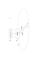
- FIG. 1 is a diagram showing an example of an outline of a wireless communication system according to this embodiment.
- FIG. 2 is a diagram showing an example of the SSB according to this embodiment.
- FIG. 3 is a diagram showing an example of an SS burst set according to this embodiment.
- FIG. 4 is a diagram showing an example of BWP in this embodiment.
- FIG. 5 is a diagram showing an example of first and second initial DL/UP BWPs according to this embodiment.
- FIGS. 6A and 6B are diagrams showing examples of first and second initial DL BWPs according to this embodiment.
- FIG. 7 is a diagram showing an example of SSB, PF and PO according to this embodiment.
- FIG. 8 is a diagram showing an example of SSB, PF and PO according to this embodiment.
- FIG. 1 is a diagram showing an example of an outline of a wireless communication system according to this embodiment.
- FIG. 2 is a diagram showing an example of the SSB according to this embodiment.
- FIG. 9 is a flow chart showing an example of operation for setting PDCCH monitoring opportunities for paging according to the present embodiment.
- FIG. 10 is a diagram showing an example of the relationship between SSB and RO and RA preambles according to this embodiment.
- FIG. 11 is a diagram showing another example of the relationship between SSB and RO and RA preambles according to this embodiment.
- FIG. 12 is a flowchart showing an example of the RO and/or RA preamble selection operation according to this embodiment.
- FIG. 13 is a diagram showing an example of the MIB according to this embodiment.
- FIG. 14 is a flow chart showing an example of the operation at the time of MIB reception according to this embodiment.
- FIG. 15 is a diagram showing an example of BWP-DownlinkCommon according to this embodiment.
- FIG. 16 is a diagram showing an example of BWP-UplinkCommon according to this embodiment.
- FIG. 17 is a diagram showing an example of RACH-ConfigCommon according to this embodiment.
- FIG. 18 is a diagram showing an example of RACH-ConfigCommonTwoStepRA according to this embodiment.
- FIG. 19 is a diagram showing an example of the hardware configuration of each device in the wireless communication system according to this embodiment.
- FIG. 20 is a diagram showing an example of a functional block configuration of a terminal according to this embodiment.
- FIG. 21 is a diagram showing an example of the functional block configuration of the base station according to this embodiment.
- FIG. 1 is a diagram showing an example of an overview of a wireless communication system according to this embodiment.
- the wireless communication system 1 may include a terminal 10, a base station 20, and a core network 30.
- the numbers of terminals 10 and base stations 20 shown in FIG. 1 are merely examples, and are not limited to the numbers shown.
- the radio communication system 1 is a system that communicates in compliance with the radio access technology (RAT) defined by 3GPP.
- RAT radio access technology
- a radio access technology to which the radio communication system 1 conforms for example, a fifth generation RAT such as NR is assumed, but not limited to this, for example, a fourth generation RAT such as LTE, LTE-Advanced, etc.
- One or more RATs can be used, such as a 6th generation RAT or later, or a non-3GPP RAT such as Wi-Fi®.
- the wireless communication system 1 is a form of communication that conforms to a wireless access technology defined by a standard development organization different from 3GPP (for example, Institute of Electrical and Electronics Engineers (IEEE), Internet Engineering Task Force (IETF)). may be
- the terminal 10 is a device corresponding to a terminal (for example, UE (User Equipment)) defined in the 3GPP specifications.
- the terminal 10 is, for example, a predetermined terminal or device such as a smartphone, a personal computer, a car, an in-vehicle terminal, an in-vehicle device, a stationary device, a telematics control unit (TCU), and an IoT device such as a sensor.
- Terminal 10 may also be called a User Equipment (UE), a Mobile Station (MS), a User Terminal, a Radio apparatus, a subscriber terminal, an access terminal, and so on.
- the terminal 10 may be a so-called Reduced capability (RedCap) terminal, such as an industrial wireless sensor, a surveillance camera (video service), a wearable device, etc. There may be.
- the terminal 10 may be mobile or stationary.
- the terminal 10 is configured to be able to communicate using one or more RATs such as NR, LTE, LTE-Advanced, Wi-Fi (registered trademark), for example.
- RATs such as NR, LTE, LTE-Advanced, Wi-Fi (registered trademark), for example.
- the terminal 10 is not limited to a terminal defined in the 3GPP specifications, and may be a terminal complying with standards defined by other standard development organizations. Also, the terminal 10 does not have to be a standard-compliant terminal.
- the base station 20 is a device corresponding to a base station (eg, gNodeB (gNB) or eNB) defined in the 3GPP specifications.
- the base station 20 forms one or more cells C and communicates with the terminal 10 using the cells.
- Cell C may be interchangeably referred to as serving cell, carrier, component carrier (CC), and the like.
- Cell C may also have a predetermined bandwidth.
- base station 20 may communicate with terminal 10 using one or more cell groups. Each cell group may include one or more cells C. Aggregating multiple cells C within a cell group is called carrier aggregation.
- the plurality of cells C includes a primary cell (Primary Cell: PCell) or a primary SCG cell (Primary Secondary Cell Group (SCG) Cell: PSCell) and one or more secondary cells (Secondary Cell: SCG). Communicating with the terminal 10 using two cell groups is also called dual connectivity.
- the terminal 10 is not limited to a base station defined in the 3GPP specifications, and may be a terminal complying with standards defined by other standard development organizations. Also, the terminal 10 does not have to be a base station conforming to the standards.
- Base station 20 includes gNodeB (gNB), en-gNB, Next Generation-Radio Access Network (NG-RAN) node, low-power node, Central Unit (CU), Distributed Unit (DU), gNB It may also be called -DU, Remote Radio Head (RRH), Integrated Access and Backhaul/Backhauling (IAB) node, access point, and so on.
- the base station 20 is not limited to one node, and may be composed of a plurality of nodes (for example, a combination of a lower node such as DU and an upper node such as CU).
- the core network 30 is, for example, a fifth generation core network (5G Core Network: 5GC) or a fourth generation core network (Evolved Packet Core: EPC), but is not limited to this.
- a device on the core network 30 (hereinafter also referred to as a “core network device”) may perform mobility management such as paging and location registration of the terminal 10 .
- a core network device may be connected to the base station 20 or terminal 10 via a predetermined interface (eg, S1 or NG interface).
- the core network device includes, for example, an Access and Mobility Management Function (AMF) that manages C-plane information (e.g., information related to access and mobility management), and a User that controls transmission of U-plane information (e.g., user data).
- AMF Access and Mobility Management Function
- UPF Plane Function
- the terminal 10 receives a downlink (DL) signal from the base station 20 and/or transmits an uplink (UL) signal to the base station 20 .
- DL downlink
- UL uplink
- One or more cells C are configured in the terminal 10, and at least one of the configured cells is activated.
- the maximum bandwidth of each cell is, for example, 20 MHz or 400 MHz.
- the terminal 10 performs a cell search based on a synchronization signal (eg, Primary Synchronization Signal (PSS) and/or Secondary Synchronization Signal (SSS)) from the base station 20.
- Cell search is a procedure by which the terminal 10 acquires time and frequency synchronization in a cell and detects the identifier of the cell (eg, physical layer cell ID).
- the terminal 10 determines a search space set and/or a control resource set (Control Resource Set: CORESET) based on parameters included in a Radio Resource Control (RRC) message (hereinafter referred to as "RRC parameters").
- CORESET may consist of frequency domain resources (eg, a predetermined number of resource blocks) and time domain resources (eg, a predetermined number of symbols).
- RRC Radio Resource Control
- a CORESET may consist of frequency domain resources (eg, a predetermined number of resource blocks) and time domain resources (eg, a predetermined number of symbols).
- the RRC parameter may also be called an RRC information element (Information Element: IE) or the like.
- downlink control channel for example, physical downlink control channel (Physical Downlink Control Channel: PDCCH)
- DCI Downlink Control Information
- the RRC message may include, for example, an RRC setup message, an RRC reconfiguration message, an RRC resume message, an RRC reestablishment message, system information, and the like.
- DCI monitoring means that the terminal 10 blind-decodes the PDCCH candidate (PDCCH candidate) in the search space set in the assumed DCI format.
- the number of bits (also referred to as size, bit width, etc.) of the DCI format is predetermined or derived according to the number of bits of fields included in the DCI format.
- the terminal 10 specifies the number of bits in the DCI format and the scramble (hereinafter referred to as “CRC scramble”) of the cyclic redundancy check (CRC) bits (also referred to as CRC parity bits) of the DCI format.
- DCI for the terminal 10 is detected based on the Radio Network Temporary Identifier (RNTI).
- RNTI Radio Network Temporary Identifier
- DCI monitoring is also called PDCCH monitoring, monitor, and the like.
- a given period for monitoring DCI or PDCCH is also called a PDCCH monitoring occasion.
- a search space set is a set of one or more search spaces.
- a search space set commonly used by one or more terminals 10 (hereinafter referred to as a “common search space (CSS) set”) and a terminal-specific search space set (UE-specific search space (USS) set), and
- the search space set includes a search space set for paging (hereinafter referred to as “paging search space”), a search space set for random access (RA) (hereinafter referred to as "RA search space”), and system information (hereinafter referred to as “system information search space”), etc. may also be included.
- Terminal 10 may receive information regarding the configuration of each search space set.
- the terminal 10 monitors PDCCH using a search space set (or search space) at PDCCH monitoring opportunities and receives (or detects) DCI that is CRC-scrambled by a specific RNTI.
- the terminal 10 receives a downlink shared channel scheduled using the DCI (for example, a physical downlink shared channel (Physical Downlink Shared Channel: PDSCH)) and/or receives an uplink shared channel (for example, a physical uplink shared channel (Physical Controls transmission of Uplink Shared Channel: PUSCH)).
- a downlink shared channel scheduled using the DCI for example, a physical downlink shared channel (Physical Downlink Shared Channel: PDSCH)
- an uplink shared channel for example, a physical uplink shared channel (Physical Controls transmission of Uplink Shared Channel: PUSCH)
- the system information broadcast in cell C may include a master information block (MIB) and/or one or more system information blocks (SIB).
- the MIB is broadcast via a broadcast channel (for example, a physical broadcast channel (PBCH)).
- PBCH physical broadcast channel
- MIB and SIB1 are also called Minimum System Information, and SIB1 is also called Remaining Minimum System Information (RMSI).
- SIB1 and SIBx other than SIB1 are broadcast via PDSCH.
- SIB1 is cell-specific, and SIBx other than SIB1 may be cell-specific or area-specific containing one or more cells.
- the SSB is a block containing at least one of a synchronization signal, a PBCH, and a demodulation reference signal (DM-RS) for the PBCH.
- An SSB may also be called an SS/PBCH block, an SS block, and so on.
- FIG. 2 is a diagram showing an example of the SSB according to this embodiment. Note that FIG. 2 is merely an example, and the SSB is not limited to the illustrated one. As shown in FIG. 2, the SSB consists of a predetermined number of symbols (e.g., four consecutive symbols) as time domain resources and a predetermined number of subcarriers (e.g., consecutive four symbols) as frequency resource resources. 240 subcarriers).
- symbols e.g., four consecutive symbols
- subcarriers e.g., consecutive four symbols
- the PSS is transmitted in the first symbol within the SSB and mapped to 127 subcarriers.
- the remaining subcarriers of the first symbol may be empty.
- SSS is transmitted in the third symbol within SSB and is mapped to the same 127 subcarriers as PSS.
- a predetermined number (8 or 9) of empty subcarriers may be provided at both ends of the SSS.
- the PBCH is transmitted on the 2nd and 4th symbols in the SSB and mapped to 240 subcarriers. Also, the PBCH is mapped to 48 subcarriers at both ends of the SSS.
- a DMRS (not shown) may be mapped to some subcarriers indicated as PBCH in FIG.
- An SS burst set which is a set of one or more SSBs, is transmitted at predetermined intervals.
- the SS burst set may also be called an SS burst or the like.
- the terminal 10 receives information (hereinafter referred to as "ssb-periodicityServingCell") regarding the period of the SSB or SS burst set (hereinafter referred to as "SSB period").
- the ssb-periodicityServingCell may indicate the SSB period (eg, 5, 10, 20, 40, 80 or 160 ms).
- Each SSB in the SS burst set is identified by an index (hereinafter referred to as "SSB index").
- SSB index an index
- SSBs with different indexes in the SS burst set correspond to different beams, and may be transmitted by sequentially switching beam directions by beam sweeping.
- the SSB (single or multiple SSBs) of a particular index within the SS burst set may be transmitted in all directions.
- the terminal 10 receives information about SSB transmission within the SS burst set (hereinafter referred to as "ssb-PositionsInBurst").
- ssb-PositionsInBurst may be a bitmap containing bits corresponding to each SSB in the SS burst set, with the value of each bit indicating whether the corresponding SSB is actually transmitted.
- a bit value of '1' may indicate that the corresponding SSB is actually transmitted
- a bit value of '0' may indicate that the corresponding SSB is not actually transmitted.
- ssb-PositionsInBurst is not limited to the above, and may be any information regarding SSB transmission within the SS burst set.
- ssb-PositionsInBurst may be cell specific.
- ssb-PositionsInBurst is included in SIB1, for example, but may be included in other RRC messages.
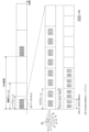
- FIG. 3 is a diagram showing an example of an SS burst set according to this embodiment.
- FIG. 3 is only an example, and the number of SSBs in the SS burst set, the SSB period, the subcarrier interval, the beam direction, the arrangement position of the SS burst set, etc. are not limited to those shown in the drawing.
- SSBs #0 to #7 in the SS burst set are transmitted from the base station 20 at different times with beams #0 to #7 having different directivities.
- An SS burst set containing one or more SSBs is placed in the first or second half frame (eg, 5 ms) of a radio frame, and is repeated at the SSB cycle.
- the SS burst set including SSB #0 to #7 is arranged in the first half frame of the radio frame and repeated with an SSB period of 20 ms.
- the positions within the half-frame where SSB#0-#7 are transmitted may vary depending on the subcarrier spacing.
- ssb-PositionsInBurst is an 8-bit bitmap corresponding to each of SSB #0 to #7 and is set to "11111111". Therefore, the terminal 10 recognizes that all SSBs #0 to #7 in the SS burst set are transmitted. Thus, the terminal 10 determines the SSBs actually transmitted within the SS burst set based on ssb-PositionsInBurst.
- FIG. 3 shows an example of multi-beam operation, it is also applicable to single-beam operation.
- a specific SSB eg, only SSB#0
- the bit corresponding to that specific SSB in ssb-PositionsInBurst is set to '1', and the other bits may be set to '0'.
- the BWP may include a BWP for DL (hereinafter referred to as "DL BWP") and/or a BWP for UL (hereinafter referred to as "UL BWP").
- the BWP includes a BWP that is set unique to the cell (hereinafter referred to as "initial BWP"), a BWP that is uniquely set to the terminal 10 (hereinafter referred to as "dedicated BWP”), may include
- the initial BWP may be used for initial access and/or common to one or more terminals 10 .
- the initial BWP may include an initial BWP for DL (hereinafter referred to as "initial DL BWP") and an initial BWP for UL (hereinafter referred to as “initial UL BWP”).
- DL BWP initial BWP for DL
- UL BWP initial BWP for UL
- Dedicated BWP is also called “UE-specific BWP”.
- Initial DL BWP and/or initial UL BWP (hereinafter referred to as "initial DL/UL BWP") is equal to CORESET#0 determined based on a specific parameter in the MIB (hereinafter referred to as "pdcch-ConfigSIB1”) may Alternatively, the initial DL/UL BWP may be set in the terminal 10 based on information on the initial DL/UL BWP received by the terminal 10 from the base station 20 (hereinafter referred to as "initial DL/UL BWP information"). .
- the initial DL/UL BWP information includes information indicating the location and/or bandwidth of the frequency domain of the initial DL/UL BWP (hereinafter referred to as “locationAndBandwidth") and information indicating subcarrier spacing (hereinafter referred to as “subcarrierSpacing”). , and information about a cyclic prefix (hereinafter referred to as “cyclicPrefix”).
- Initial DL/UL BWP information is a cell-specific RRC parameter and may be included in SIB1 or other RRC messages
- an individual BWP for DL (hereinafter referred to as “individual DL BWP”) is a DL BWP with bwp-id ⁇ 0 (that is, DL BWP#bwp-id), and an individual BWP for UL (hereinafter referred to as “individual UL BWP”) may be a UL BWP with bwp-id ⁇ 0 (that is, UL BWP#bwp-id).
- DL BWPs and/or one or more individual UL BWPs When one or more individual DL BWPs and/or one or more individual UL BWPs are configured in the terminal 10, one individual DL BWP and/or one individual UL BWP may be activated.
- SSB is transmitted in one or more DL BWPs.
- CD-SSB is an SSB associated with a particular cell and may be associated with SIB1.
- NCD-SSBs are SSBs that are not associated with a particular cell and may not be associated with SIB1.
- FIG. 4 is a diagram showing an example of the DL BWP in this embodiment.
- DL BWP is shown in FIG. 4, it goes without saying that UL BWP may also be set.
- X is a number given for convenience to distinguish SSBs in different frequency domains, and does not indicate an SSB index that identifies each SSB within an SS burst set.
- NGCI is the cell C identifier.
- SSB1 is CD-SSB and is associated with cell #5 (and/or SIB1 broadcasted in cell #5).
- SSB3 is CD-SSB and is associated with cell #6 (and/or SIB1 broadcast on cell #6).
- SSB2 and SSB4 are NCD-SSBs and are not associated with SIB1 of a particular cell.
- terminals 10A and 10B are connected to cell #5, so they may detect SSB1 associated with cell #5 and set initial DL BWP#0 based on SSB1.
- the terminal 10A sets individual DL BWP #1 and #2 based on parameters unique to the terminal 10A.
- Terminal 10A may use individual DL BWP #1 and #2 by switching over time.
- terminal 10B sets individual DL BWP#1 based on parameters specific to terminal 10B.
- terminal 10C since terminal 10C is connected to cell #6, it may detect SSB3 associated with cell #6 and set initial DL BWP#0 based on SSB3.
- Terminal 10C sets individual DL BWP #1 and #2 based on parameters specific to terminal 10C.
- Each of the terminals 10A-10C may perform measurement based on at least one SSB in the initial DL BWP or the individual DL BWP.
- received power for example, reference signal received power (RSRP)
- RSRP measured based on SSB may be referred to as Synchronization Signal (SS)-RSRP.
- the measurement may be performed for at least one of radio resource management (RRM), radio link monitoring (RLM), and mobility.
- RRM radio resource management
- RLM radio link monitoring
- mobility mobility
- the terminal 10 may be a RedCap terminal intended for lower performance or price range than existing terminals supported by Release 15 or 16 of 3GPP.
- RedCap terminals are expected to be used, for example, in industrial wireless sensors, surveillance cameras (video serveilance), wearable devices, and the like.
- the maximum bandwidth supported by a RedCap terminal may be narrower than the maximum bandwidth of existing terminals.
- multiple initial DL BWPs may be set in such a terminal 10 .
- the initial DL/UL BWP may be set independently of the conventional initial DL/UL BWP.
- the conventional initial DL/UL BWP will be referred to as the first initial DL/UL BWP
- the initial DL/UL BWP that is set independently of the first initial DL/UL BWP will be referred to as the second initial DL/UL BWP. call.
- the initial DL/UL BWP information used for setting the first initial DL/UL BWP is referred to as the first initial DL/UL BWP information, and the above information used for setting the second initial DL/UL BWP.
- the initial DL/UL BWP information shall be referred to as the second initial DL/UL BWP information.
- the first and second initial DL/UL BWP information may each include at least one of locationAndBandwidth, subcarrierSpacing and cyclicPrefix.
- the first initial DL/UL BWP may be set based on CORESET#0 or the frequency position and/or bandwidth indicated by locationAndBandwidth in the first initial DL/UL BWP information.
- the first initial DL/UL BWP may be set for existing terminals and/or RedCap terminals.
- the second initial DL/UL BWP may be the DL/UL BWP of the frequency location and/or bandwidth specified in advance, or the second initial DL/UL BWP information It may be set based on the frequency location and/or bandwidth indicated by locationAndBandwidth.
- a second initial DL/UL BWP may be set in the RedCap terminal.
- the above subcarrierSpacing and/or cyclicPrefix may or may not be set.
- the second initial DL/UL DWP may be called a separate initial DL/UL BWP, an additional initial DL/UL BWP, or the like.
- a RedCap terminal may use a second initial UL BWP during initial access (eg after message 3) and/or after initial access (eg after message 4).
- the RedCap terminal may use the second initial DL BWP after the initial access (for example, after message 4) or before the initial access (for example, after receiving configuration information for the second initial DL BWP). may be used for
- CORESET#0 may not be set.
- SIB1 may not be transmitted in the second initial DL BWP.
- at least part of the second initial DL BWP may or may not overlap with the first initial UL BWP.
- at least part of the second initial UL BWP may or may not overlap with the first initial UL BWP.
- the bandwidth of each of the second initial DL BWP and the second initial UL BWP may be narrower than the maximum bandwidth of the RedCap terminal.
- FIG. 5 is a diagram showing an example of first and second initial DL/UL BWPs according to this embodiment. As shown in FIG. 5, one end of the first and second initial UL BWPs are aligned to share a resource region for an uplink control channel (eg, Physical Uplink Control Channel (PUCCH)). may In Time Division Duplex (TDD), the second initial UL BWP and the second initial DL BWP may be identical. Note that FIG. 5 is merely an example, and the bandwidth and arrangement of the first and second initial DL/UL BWPs are not limited to those shown.
- PUCCH Physical Uplink Control Channel
- FIGS. 6(A) and (B) are diagrams showing examples of the first and second initial DL BWPs according to this embodiment.
- SSB eg, CD-SSB
- the terminal 10 which transmits and receives data in the second initial DL BWP, performs RF retuning for SSB-based measurement, and may need RF retuning again for data transmission and reception after measurement. is assumed.
- CORESET#0 may be set to the first initial DL BWP and may not be set to the second initial DL BWP. As shown in FIG.
- support information information on BWP support in which SSB is not transmitted and/or CORESET#0 is not set
- support information information on the capability of the terminal 10 (hereinafter referred to as "UE capability”).
- UE capability may be transmitted from the terminal 10 to the base station 20 .
- SSB (eg, CD-SSB) is transmitted in the first initial DL BWP
- SSB (eg, NC-SSB) is transmitted in the second initial DL BWP.
- FIG. 6B unlike FIG. 6A, there is no need to perform RF retuning for measurement. Therefore, SSB transmission in the second initial DL BWP can contribute to reducing the processing load on terminal 10 .
- the terminal 10 if a second initial DL BWP is set in cell C where the first initial DL BWP is set and SSB can be transmitted in the second initial DL BWP, the terminal 10 Alternatively, there is a risk that it may not be possible to properly recognize which SSB of the second initial DL BWP should be operated based on. As a result, the SSB-based operation may not be properly controlled.
- the terminal 10 controls SSB-based operations based on whether or not the second initial DL BWP is set in the cell C in which the first initial DL BWP is set. For example, based on whether or not the second initial DL BWP is set in the cell C, the terminal 10 transmits SSB (hereinafter referred to as "first SSB") in the first initial DL BWP. Alternatively, it may be determined based on which of the SSBs transmitted in the second initial DL BWP (hereinafter referred to as "second SSB").
- first SSB SSB
- second SSB which of the SSBs transmitted in the second initial DL BWP
- Terminal 10 receives parameters or information from base station 20 .
- "configured” may mean receiving the parameters and/or information, or controlling the operation of the terminal 10 based on the received parameters and/or information.
- RRC parameters are exemplified below as the parameters and/or information, the parameters and/or information are not limited thereto.
- the parameters and/or information are parameters of higher layers (for example, layers higher than physical layers such as Medium Access Control (MAC) layers and Non Access Stratum (NAS) layers). may be a parameter of the physical layer.
- MAC Medium Access Control
- NAS Non Access Stratum
- the first initial DL BWP may be set in terminal 10 based on the first initial DL BWP information from base station 20 .
- the first initial DL BWP information may include at least one of locationAndBandwidth, subcarrierSpacing and cyclicPrefix.
- the first initial DL BWP information is the RRC parameters in SIB1 (e.g., "BWP” as “genericParameters” in “BWP-DownlinkCommon” as “initialDownlinkBWP” in “DownlinkConfigCommonSIB” in “ServingCellConfigCommonSIB”) may be Alternatively, the first initial DL BWP information may be specified as RRC parameters in other RRC messages (e.g., "genericParameters" in "BWP-DownlinkCommon” as "initialDownlinkBWP” in “DownlinkConfigCommon” in “ServingCellConfigCommon”). BWP”).
- the first initial DL BWP information may be cell specific.
- the second initial DL BWP may be set in the terminal 10 based on the second initial DL BWP information from the base station 20.
- the second initial DL BWP information may include at least one of locationAndBandwidth, subcarrierSpacing and cyclicPrefix.
- the second initial DL BWP information is the RRC parameters in SIB1 (for example, "BWP” as “genericParametersRedCap” in “BWP-DownlinkCommon” as “initialDownlinkBWP-RedCap” in “DownlinkConfigCommonSIB” in “ServingCellConfigCommonSIB”) may be Alternatively, the second initial DL BWP information is RRC parameters in other RRC messages (for example, as “genericParametersRedCap” in "BWP-DownlinkCommon” as "initialDownlinkBWP-RedCap” in "DownlinkConfigCommon” in "ServingCellConfigCommon” "BWP”).
- the second initial DL BWP information may be cell specific.
- the first initial UL BWP may be configured in terminal 10 based on the first initial UL BWP information from base station 20 .
- the first initial DL BWP information may include at least one of locationAndBandwidth, subcarrierSpacing and cyclicPrefix.
- the first initial UL BWP information is the RRC parameters in SIB1 (e.g., "BWP” as “genericParameters” in “BWP-UplinkCommon” as “initialUplinkBWP” in “UplinkConfigCommonSIB” in “ServingCellConfigCommonSIB”) may be Alternatively, the first initial UL BWP information may include RRC parameters in other RRC messages (e.g., "genericParameters" in "BWP-UplinkCommon” as “initialUplinkBWP” in “UplinkConfigCommon” in “ServingCellConfigCommon”). BWP”).
- the second initial UL BWP information may be cell specific.
- the second initial UL BWP may be set in the terminal 10 based on the second initial UL BWP information from the base station 20.
- the second initial UL BWP information may include at least one of locationAndBandwidth, subcarrierSpacing and cyclicPrefix.
- the second initial UL BWP information is the RRC parameters in SIB1 (for example, "BWP” as “genericParametersRedCap” in “BWP-UplinkCommon” as “initialUplinkBWP-RedCap” in “UplinkConfigCommonSIB” in “ServingCellConfigCommonSIB”) may be Alternatively, the second initial UL BWP information can be specified as RRC parameters in other RRC messages (for example, as “genericParametersRedCap” in "BWP-UplinkCommon” as "initialUplinkBWP-RedCap” in "UplinkConfigCommon” in “ServingCellConfigCommon” "BWP”).
- the second initial UL BWP information may be cell specific.
- the first SSB may be set in the terminal 10 based on information regarding transmission of the first SSB (hereinafter referred to as "first SSB transmission information").
- the first SSB transmission information includes information on the first SSB transmission within the SS burst set (hereinafter referred to as "ssb-PositionsInBurst”), information on the SSB period of the first SSB (hereinafter referred to as "ssb-periodicityServingCell").
- the first SSB transmission information may be RRC parameters in SIB1 (e.g. parameters in 'ServingCellConfigCommonSIB') or RRC parameters in other RRC messages (e.g. parameters in 'ServingCellConfigCommon').
- SIB1 e.g. parameters in 'ServingCellConfigCommonSIB'
- RRC parameters in other RRC messages e.g. parameters in 'ServingCellConfigCommon'
- the first SSB transmission information may be cell specific.
- the second SSB may be set in the terminal 10 based on information regarding transmission of the second SSB (hereinafter referred to as "second SSB transmission information").
- the second SSB transmission information includes information on the second SSB transmission within the SS burst set (hereinafter referred to as “additional SSB-PositionsInBurst”), information on the SSB period of the second SSB (hereinafter referred to as "additional SSB-periodicityServingCell”).
- the second SSB transmission information may be RRC parameters in SIB1 (e.g. parameters in 'ServingCellConfigCommonSIB') or RRC parameters in other RRC messages (e.g. parameters in 'ServingCellConfigCommon').
- SIB1 e.g. parameters in 'ServingCellConfigCommonSIB'
- RRC parameters in other RRC messages e.g. parameters in 'ServingCellConfigCommon'
- the second SSB transmission information may be cell specific.
- the first SSB transmission information (ssb-PositionsInBurst , and/or ssb-periodicityServingCell, and/or ss-PBCH-BlockPower, and/or ssb-SMTC) may be applied to the second SSB transmission information.
- the terminal 10 may use the first SSB (that is, give priority to the first SSB). good).
- the transmission resources may be, for example, time domain and/or frequency domain resources.
- pdcch-ConfigCommon Information related to PDCCH configuration in the first initial DL BWP
- pdcch-ConfigCommon contains information about paging search space (hereinafter referred to as “pagingSearchSpace”), information about RA search space (hereinafter referred to as “ra-SearchSpace”), information about CORESET (hereinafter referred to as "commonControlResourceSet”), and paging It may include at least one of information about the first PDCCH monitoring opportunity within the paging occasion (PO) (hereinafter referred to as "firstPDCCH-MonitoringOccasionOfPO").
- pagingSearchSpace information about paging search space
- ra-SearchSpace information about RA search space
- CORESET hereinafter referred to as "commonControlResourceSet”
- paging It may include at least one of information about the first PDCCH monitoring opportunity within the paging occasion (PO) (hereinafter referred to as "firstPDCCH-Monit
- pdcch-ConfigCommon may be the RRC parameter in SIB1 (eg, the parameter in 'BWP-DownlinkCommon' as 'initialDownlinkBWP' in 'DownlinkConfigCommonSIB' in 'ServingCellConfigCommonSIB').
- pdcch-ConfigCommon may be RRC parameters in other RRC messages (eg, parameters in 'BWP-DownlinkCommon' as 'initialDownlinkBWP' in 'DownlinkConfigCommon' in 'ServingCellConfigCommon').
- pdcch-ConfigCommon may be cell specific.
- pdcch-ConfigCommon may be called first downlink control channel setting information or the like.
- pdcch-ConfigCommonRedCap Information related to PDCCH configuration in the second initial DL BWP (hereinafter referred to as "pdcch-ConfigCommonRedCap”) may be configured in the terminal 10.
- pdcch-ConfigCommonRedCap may include at least one of pagingSearchSpace, ra-SearchSpace, commonControlResourceSet, and firstPDCCH-MonitoringOccasionOfPO.
- pdcch-ConfigCommonRedCap may be an RRC parameter in SIB1 (eg, a parameter in 'BWP-DownlinkCommon' as 'initialDownlinkBWP' in 'DownlinkConfigCommonSIB' in 'ServingCellConfigCommonSIB').
- pdcch-ConfigCommonRedCap may be an RRC parameter in another RRC message (eg, a parameter in 'BWP-DownlinkCommon' as 'initialDownlinkBWP' in 'DownlinkConfigCommon' in 'ServingCellConfigCommon').
- pdcch-ConfigCommonRedCap may be cell specific.
- pdcch-ConfigCommonRedCap may be called second downlink control channel setting information or the like.
- rach-ConfigCommon Information related to random access configuration in the first initial DL BWP (hereinafter referred to as “rach-ConfigCommon”) may be configured in the terminal 10 .
- rach-ConfigCommon is information indicating the number of first SSBs per RO and/or the number of RA preambles per first SSB transmission (hereinafter referred to as “ssb-perRACH-OccasionAndCB-PreamblesPerSSB”); It may include at least one piece of information (hereinafter referred to as “rsrp-ThresholdSSB”) regarding the received power (for example, RSRP) threshold of the first SSB.
- rsrp-ThresholdSSB the received power (for example, RSRP) threshold of the first SSB.
- rach-ConfigCommon may be the RRC parameter in SIB1 (eg, the parameter in 'BWP-UplinkCommon' as 'initialUplinkBWP' in 'UplinkConfigCommonSIB' in 'ServingCellConfigCommonSIB').
- rach-ConfigCommon may be RRC parameters in other RRC messages (eg, parameters in 'BWP-UplinkCommon' as 'initialUplinkBWP' in 'UplinkConfigCommon' in 'ServingCellConfigCommon').
- rach-ConfigCommon may be cell-specific.
- rach-ConfigCommon may be called the first random access parameter, and so on.
- rach-ConfigCommonRedCap Information related to the random access setting in the second initial DL BWP (hereinafter referred to as “rach-ConfigCommonRedCap”) may be set in the terminal 10.
- rach-ConfigCommonRedCap is information indicating the number of second SSBs per RO and/or the number of RA preambles per second SSB transmission (hereinafter referred to as “ssb-perRACH-OccasionAndCB-PreamblesPerSSB”); It may include at least one piece of information (hereinafter referred to as “rsrp-ThresholdSSB”) regarding the threshold of the received power (for example, RSRP) of the second SSB.
- rsrp-ThresholdSSB the threshold of the received power (for example, RSRP) of the second SSB.
- rach-ConfigCommonRedCap may be an RRC parameter in SIB1 (eg, a parameter in 'BWP-UplinkCommon' as 'initialUplinkBWP' in 'UplinkConfigCommonSIB' in 'ServingCellConfigCommonSIB').
- rach-ConfigCommonRedCap may be an RRC parameter in another RRC message (eg, parameter in 'BWP-UplinkCommon' as 'initialUplinkBWP' in 'UplinkConfigCommon' in 'ServingCellConfigCommon').
- rach-ConfigCommonRedCap may be cell specific.
- the rach-ConfigCommonRedCap may be called a second random access parameter or the like.
- PCCH-Config Information related to paging configuration in the first initial DL BWP (hereinafter referred to as “PCCH-Config”) may be configured in the terminal 10 .
- PCCH-Config includes information about the paging cycle (hereinafter referred to as "PagingCycle”), firstPDCCH-MonitoringOccasionOfPO, information indicating the number of paging frames (paging frmae: PF) in the paging cycle and/or time offset (hereinafter referred to as “nAndPagingFrameOffset” ), information on the number of POs per PF (hereinafter referred to as “ns”), and information on the number of PDCCH monitoring opportunities per SSB in a PO (hereinafter referred to as “nrofPDCCH-MonitoringOccasionPerSSB-InPO”).
- PagingCycle information about the paging cycle
- firstPDCCH-MonitoringOccasionOfPO information indicating the number of
- PCCH-Config may be RRC parameters in SIB1 (eg, parameters in 'DownlinkConfigCommonSIB' in 'ServingCellConfigCommonSIB').
- PCCH-Config may be cell specific.
- PCCH-Config may be called first paging configuration information or the like.
- PCCH-ConfigRedCap Information related to paging settings in the second initial DL BWP (hereinafter referred to as "PCCH-ConfigRedCap”) may be set in the terminal 10.
- PCCH-ConfigRedCap may include at least one of defaultPagingCycle, firstPDCCH-MonitoringOccasionOfPO, nAndPagingFrameOffset, ns and nrofPDCCH-MonitoringOccasionPerSSB-InPO.
- PCCH-ConfigRedCap may be an RRC parameter in SIB1 (eg, a parameter in 'DownlinkConfigCommonSIB' in 'ServingCellConfigCommonSIB').
- PCCH-Config may be cell specific.
- PCCH-ConfigRedCap may be referred to as second paging configuration information or the like.
- the terminal 10 monitors the PDCCH at the PDCCH monitoring opportunity and receives DCI used for scheduling the PDSCH that transmits the paging message.
- the DCI may be CRC scrambled with a specific RNTI (eg Paging(P)-RNTI).
- Terminal 10 may determine the PDCCH monitoring opportunity based on whether the second initial DL BWP is configured in cell C where the first initial DL BWP is configured.
- the terminal 10 determines paging frames based on at least one of the DRX cycle, the number of PFs in the DRX cycle, the time offset and the identifier of the terminal 10 .
- PF is, for example, a radio frame (RF) including PO.
- the terminal 10 may determine the identification number of the PF (hereinafter referred to as "system frame number (SFN)”) based on Equation (1) below.
- SFN system frame number
- T (T div N) * (UE_ID mod N)
- N the number of PFs in T
- PF_offset is a predetermined offset
- UE_ID is determined based on the terminal 10 identifier (eg, 5G-S-TMSI). value.
- T may be determined based on the PagingCycle.
- PagingCycle may indicate, for example, 32, 64, 128 or 256 RF.
- N and/or PF_offset may be determined based on the nAndPagingFrameOffset.
- the terminal 10 may determine POs in the PF based on at least one of the ID of the search space used as the paging search space, firstPDCCH-MonitoringOccasionOfPO, and nrofPDCCH-MonitoringOccasionPerSSB-InPO.
- PO is, for example, a set of one or more PDCCH monitoring occasions for paging, and S*X consecutive PDCCH monitoring occasions from the time position indicated by firstPDCCH-MonitoringOccasionOfPO (e.g., S*X consecutive excluding UL symbols symbol).
- Each PDCCH monitoring occasion within the PO may consist of a predetermined number of symbols.
- firstPDCCH-MonitoringOccasionOfPO may, for example, indicate the time position (eg, symbol position) of the first PDCCH monitoring occasion within the PF.
- S is the number of SSBs actually transmitted within the SS burst set, and may be indicated by ssb-PositionsInBurst or additional SSB-PositionsInBurst.
- X is the number of PDCCH monitoring occasions per SSB in PO, which may be determined based on nrofPDCCH-MonitoringOccasionPerSSB-InPO.
- nrofPDCCH-MonitoringOccasionPerSSB-InPO indicates, for example, that the number of PDCCH monitoring occasions per SSB in PO is either 2 to 4, and if nrofPDCCH-MonitoringOccasionPerSSB-InPO is not set, the number of PDCCH monitoring occasions is 1 It may be shown that
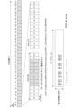
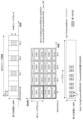
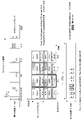
- 7 and 8 are diagrams showing examples of SSB, PF and PO according to this embodiment.
- 7 and 8 show an example of the first and second SSBs, PFs and POs in the first and second initial DL BWPs, respectively, while the first and second SSBs in the first and second initial DL BWPs
- the settings of SSB, PF and PO of 2 are not limited to those shown in the figure, and can be appropriately changed by setting various parameters.
- T 32 RFs
- nAndPagingFrameOffset may indicate that PFs are placed every 1 RF within T (oneT).
- the terminal 10 may determine the PF for the terminal 10 (here, RF#0) among the 32 PFs in T based on the UE_ID.
- firstPDCCH-MonitoringOccasionOfPO for the first initial DL BWP indicates the fifth symbol from the first in symbols #0 to #139 in the PF (that is, symbol #4 of slot #0).
- the PO is composed of S*X (here, 8) PDCCH monitoring opportunities, and SSB #0 to #7 are the first to eighth PDCCH monitoring opportunities in the PO (that is, symbols of slot #0 #4 to #11 PDCCH monitoring occasions) may be supported. For multi-beam operation, the terminal 10 may assume that the corresponding SSB and PDCCH DM-RSs are quasi-collocated at each PDCCH monitoring occasion in the PO.
- nAndPagingFrameOffset indicates that PFs are placed every eight RFs within T (oneEightT) and a time offset of "2". good.
- the terminal 10 may determine the PF for the terminal 10 (here, RF#2) among the 4 PFs in T based on the UE_ID.
- firstPDCCH-MonitoringOccasionOfPO for the second initial DL BWP is symbol #284 in symbols #0-#1119 in RF#0-#7 (that is, symbol #4 in slot #0 of PF#2). ).
- a symbol index is attached to each slot in each RF, but symbol indexes #0 to #1119 may be attached to all symbols in RF #0 to #7.
- the terminal 10 determines four consecutive symbols from symbol #4 in slot #0 of RF#2 as PO.
- the PO is composed of S*X (here, 4) PDCCH monitoring opportunities, and SSB #0 to #4 are the first to fourth PDCCH monitoring opportunities in the PO (that is, symbols of slot #0). #4 to #7 PDCCH monitoring occasions) may be supported.
- Terminal 10 may assume that the corresponding SSB and PDCCH DM-RSs are quasi-colocated at each PDCCH monitoring occasion in the PO.
- the terminal 10 has parameters for the first initial DL BWP (eg, first SSB transmission information and pdcch-ConfigCommon) and parameters for the second initial DL BWP (eg, , second SSB transmission information and pdcch-ConfigCommonRedCap) can be set independently. Therefore, the terminal 10 sets the first initial DL BWP or the second initial DL based on whether the second initial DL BWP is set and/or whether a predetermined condition is satisfied. Determine which parameters for BWP to set PDCCH monitoring occasions for paging based on.
- first initial DL BWP eg, first SSB transmission information and pdcch-ConfigCommon
- parameters for the second initial DL BWP eg, second SSB transmission information and pdcch-ConfigCommonRedCap
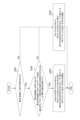
- FIG. 9 is a flowchart showing an example of operation for determining PDCCH monitoring opportunities for paging according to the present embodiment.
- the terminal 10 has the first initial DL BWP set.
- the terminal 10 determines whether or not the second initial DL BWP is set.
- step S102 when the terminal 10 is configured with the second initial DL BWP, the terminal 10 transmits the second SSB in the second initial DL BWP, configures the paging search space in the second initial DL BWP, Then, it is determined whether or not conditions related to at least one of the capabilities of the terminal 10 are satisfied. Specifically, the terminal 10 may determine whether at least one of the following conditions is satisfied. (a) transmission of the second SSB in the second initial DL BWP is set; (b) A paging search space is set up in the second initial DL BWP. (c) that the terminal 10 has certain capabilities;
- the above condition (a) may be that the second SSB transmission information (eg, at least one of additional SSB-Frequency, additional SSB-PositionsInBurst, and additional SSB-PeriodicityServingCell) is set.
- the above condition (b) is that pagingsearchspace (for example, a search space ID of a paging search space) is set in pdcch-ConfigCommonRedCap, or that pagingsearchspace and commonControlResourceSet are set in pdcch-ConfigCommonRedCap. good too.
- the specific capability in the above condition (c) is the capability of the terminal 10 regarding CORESET#0 and/or SSB in BWP.
- each BWP set in the terminal 10 includes the bandwidth of CORESET #0 and SSB (feature group 6-1), and/or the CORESET #0 and SSB It may be to allow BWPs that do not include bandwidth (feature group 6-1a).
- step S103 the terminal 10 sets the additional SSB-PositionsInBurst and/or the second initial Based on pdcch-ConfigCommonRedCap related to PDCCH configuration in DL BWP, PDCCH monitoring opportunities for paging are determined.
- step S103 if the search space ID indicated by pagingsearchspace in pdcch-ConfigCommonRedCap is other than 0, terminal 10 performs PDCCH monitoring for paging based on additionalSSB-PositionsInBurst and/or pdcch-ConfigCommonRedCap. Opportunity may be determined. For example, as shown in FIG. 8, the terminal 10 sets PDCCH monitoring opportunities for paging based on additionalSSB-PositionsInBurst and firstPDCCH-MonitoringOccasionOfPO in pdcch-ConfigCommonRedCap from symbol #4 in slot #0 in RF #2 to symbol #4 in slot #0 in RF #2. #7 may be determined. On the other hand, when the search space ID is 0, the terminal 10 may determine the PDCCH monitoring opportunity for SIB1 as the PDCCH monitoring opportunity for paging.
- the terminal 10 may determine PDCCH monitoring opportunities for paging based on pcch-ConfigRedCap instead of or in addition to pdcch-ConfigCommonRedCap.
- the terminal 10 is based on at least one of pdcch-ConfigCommonRedCap or firstPDCCH-MonitoringOccasionOfPO in pcch-ConfigRedCap, nrofPDCCH-MonitoringOccasionPerSSB-InPO in pcch-ConfigRedCap, defaultPagingCycle in pcch-ConfigRedCap, and nAndPagingFrameOffset in pcch-ConfigRedCap. , may determine PDCCH monitoring occasions for paging.
- step S104 The terminal 10 determines PDCCH monitoring opportunities for paging based on ssb-PositionsInBurst for the first SSB and/or pdcch-ConfigCommon for PDCCH configuration in the first initial DL BWP.
- step S104 when the search space ID indicated by pagingsearchspace in pdcch-ConfigCommon is other than 0, terminal 10 performs PDCCH monitoring for paging based on ssb-PositionsInBurst and/or pdcch-ConfigCommon.
- Opportunity may be determined.
- the terminal 10 sets PDCCH monitoring opportunities for paging based on ssb-PositionsInBurst and firstPDCCH-MonitoringOccasionOfPO in pdcch-ConfigCommon to symbols #4 to symbols #4 in slot #0 in RF #0. #11 may be determined.
- the terminal 10 may determine the PDCCH monitoring opportunity for SIB1 as the PDCCH monitoring opportunity for paging.
- the terminal 10 may determine PDCCH monitoring opportunities for paging based on pcch-Config instead of or in addition to pdcch-ConfigCommon. For example, the terminal 10, based on at least one of pdcch-ConfigCommonRedCap or firstPDCCH-MonitoringOccasionOfPO in pcch-Config, nrofPDCCH-MonitoringOccasionPerSSB-InPO in pcch-Config, defaultPagingCycle in pcch-Config and nAndPagingFrameOffset in pcch-Config , may determine PDCCH monitoring occasions for paging.
- pdcch-ConfigCommonRedCap or firstPDCCH-MonitoringOccasionOfPO in pcch-Config
- nrofPDCCH-MonitoringOccasionPerSSB-InPO in pcch-Config
- defaultPagingCycle in pcch-Con
- the terminal 10 can receive paging messages based on the DCI detected at PDCCH monitoring occasions.
- the terminal 10 transmits the RA preamble.
- the terminal 10 determines the RA preamble and/or the RO used to transmit the RA preamble based on whether the second initial DL BWP is configured in the cell C in which the first initial DL BWP is configured. You may
- the RA preamble is a predetermined sequence and is also called PRACH preamble or preamble, preamble sequence, message 1, PRACH, and the like.
- An RO is, for example, time domain and/or frequency domain resources for transmission of an RA preamble, and may consist of one or more symbols and M (M ⁇ 1) resource blocks. RO is also called PRACH opportunity, random access opportunity, transmission opportunity, opportunity, and so on.
- the RA preamble may be transmitted using a random access channel (PRACH).
- the RACH is a UL channel used for transmitting the RA preamble, and is also called a Physical Random Access Channel (PRACH) or the like.
- Random access procedures include contention-based random access (CBRA) and contention-free random access (CFRA). Two types are supported for CBRA and CFRA, respectively. The first type is called Type 1, Type-1 random access procedure, 4-step RACH, or 4-step random access, or the like. The second type is called Type-2, Type-2 random access procedure, 2-step RACH, or 2-step random access, or the like.
- terminal 10 randomly selects an RA preamble and transmits the selected RA preamble to base station 20 .
- the terminal 10 receives a Random Access Response (RAR) (also called message 2) via PDSCH in response to the RA preamble and transmits message 3 via PUSCH in response to the RAR.
- RAR Random Access Response
- Terminal 10 receives message 4 (collision resolution message) via PDSCH in response to message 3 .
- the terminal 10 transmits the RA preamble assigned by the base station 20 to the base station 20 .
- the terminal 10 receives RAR from the base station 20 via PDSCH according to the RA preamble. Since the RA preamble is indicated by DCI, CFRA is also called PDCCH-ordered RA.
- the terminal 10 transmits the RA preamble and message 3 in type 1 CBRA as message A, and receives message B (that is, RAR).
- message B that is, RAR
- the RA preamble in message A is also randomly selected.
- type 2 CFRA the RA preamble and message 3 indicated by the DCI from base station 20 are sent as message A and message B is received.
- the terminal 10 may select an RO and/or an RA preamble based on the RSRP of the SSB and transmit the RA preamble using the selected RO.
- the base station 20 Based on the RA preamble received from the terminal 10 and/or the RO used to transmit the RA preamble, the base station 20 recognizes which SSB the terminal 10 has received, that is, in which beamforming direction the terminal 10 is located. can. That is, the base station 20 may estimate the pseudo collocation (QCL) relationship for the terminal 10 based on the RA preamble from the terminal 10 and/or the SSB associated with the RO used to receive the RA preamble.
- the control unit 203 may control transmission of DL signals and/or reception of UL signals using the same spatial parameters (beams) as those of the SSB.
- the terminal 10 monitors the PDCCH in the RA search space, detects DCI that is CRC scrambled with a specific RNTI (eg, RA-RNTI), and uses the PDSCH scheduled by the DCI to perform type 1 and 2 CBRA and CFRA, message 4 and/or message B may be received.
- a specific RNTI eg, RA-RNTI
- FIG. 10 is a diagram showing an example of the relationship between SSB and RO and RA preambles according to this embodiment.
- FIG. 10 shows the relationship between SSB #0 to #7 (first SSB) actually transmitted in the first initial DL BWP and the RO and RA preambles in the first initial UL BWP.
- first SSB the relationship between SSB, RO, and RA preambles is not limited to that illustrated.
- RACH slots one or more slots used for transmitting RA preambles are provided in a predetermined period (hereinafter referred to as "RACH resource periodicity").
- RACH resource periodicity a predetermined period
- the RACH resource period is 10 slots
- the 2nd, 5th, and 8th slots in RF are RACH slots, but this is not limitative.
- each RACH slot may be provided with one or more ROs.
- One RO is composed of M (M ⁇ 1) resource blocks.
- one or more ROs can be allocated per RACH slot. For example, in FIG. 10, a total of 2 ROs, 2 ROs in the frequency domain and 1 RO in the time domain, are allocated per RACH slot.
- each RACH slot may contain one or more ROs in the time domain and/or frequency domain.
- An SSB is associated with one or more ROs. Also, one SSB is associated with one or more RA preambles.
- the association between SSB and RO and/or RA preambles may be indicated by ssb-perRACHOccasionAndCB-PreamblesPerSSB above.
- the ssb-perRACHOccasionAndCB-PreamblesPerSSB may indicate the number of SSBs associated with one RO and/or the number of RA preambles associated with one SSB.
- ssb-perRACHOccasionAndCB-PreamblesPerSSB indicates that one RO corresponds to one SSB ("one") and that one SSB corresponds to 8RA preambles ("n8").
- the SSB number X associated with one RO is not limited to 1, and may be a number larger than 1 (eg, 2, 4, 8, or 16) or a number smaller than 1 (eg, 1/8 , 1/4 or 1/2). If X ⁇ 1, one RO is associated with X SSBs.
- one SSB is associated with the reciprocal of X ROs.
- the number Y of RA preambles associated with one SSB is, for example, 4, 8, 12, etc., but is not limited thereto, and may be 1 or more.
- the RO and RA preamble indexes and the like associated with each SSB shown in FIG. 10 are merely examples, and are not limited to those shown.
- terminal 10 measures RSRP using SSB #0 to #7 in the SS burst set in the first initial DL BWP. At least one of SSB #0 to #7 is selected for terminal 10 based on the RSRP measurement result of SSB #0 to #7 and the threshold indicated by rsrp-ThresholdSSB. Specifically, the terminal 10 may select at least one of the SSBs #0 to #7 whose RSRP exceeds the threshold.
- terminal 10 when terminal 10 selects two SSB #0 and #1 based on RSRP and the threshold, random Select one RA preamble for . Also, the terminal 10 selects one RO from RO #0 and #1 associated with SSB #0 and #1 respectively. Terminal 10 uses the selected RO to transmit the selected RA preamble. Note that, in the case of CFRA, the terminal 10 may transmit the RA preamble indicated by DCI using the selected RO.
- type 1 CBRA or CFRA is assumed in FIG. 10, it is applicable to type 2 CBRA or CFRA.
- Information related to association of RO and/or RA preambles for message A (hereinafter referred to as “msgA-SSB-PerRACH-OccasionAndCB-PreamblesPerSSB”) may be configured in terminal 10 .
- information on the threshold of RSRP of SSB (hereinafter referred to as “msgA-RSRP-ThresholdSSB”) may be configured in the terminal 10 for type 2 CBRA or CFRA.
- Terminal 10 similar to ssb-perRACHOccasionAndCB-PreamblesPerSSB and RSRP-ThresholdSSB described in FIG.
- An RO may be selected for RA preamble transmission.
- FIG. 11 is a diagram showing another example of the relationship between SSB and RO and RA preambles according to this embodiment.
- FIG. 11 shows the relationship between SSB #0 to #3 (second SSB) actually transmitted in the second initial DL BWP and the RO and RA preambles in the second initial UL BWP.
- second SSB the relationship between SSB, RO, and RA preambles is not limited to that illustrated.
- FIG. 11 will be described with a focus on differences from FIG. 10 .
- SSsb-perRACHOccasionAndCB-PreamblesPerSSB indicates that 1/2 SSBs correspond to one RO (that is, one SSB corresponds to two ROs) ("oneHalf"), and one SSB has 16 RAs. Indicates that the preamble supports ("n16").
- terminal 10 measures RSRP using SSB #0 to #3 in the SS burst set in the second initial DL BWP. At least one of SSB #0 to #7 is selected for terminal 10 based on the RSRP measurement result of SSB #0 to #3 and the threshold indicated by rsrp-ThresholdSSB. Specifically, the terminal 10 may select at least one of the SSBs #0 to #3 whose RSRP exceeds the threshold.
- terminal 10 when terminal 10 selects SSB#1 based on RSRP and the threshold, terminal 10 randomly selects one RA preamble from RA preambles #15 to #31 associated with SSB#1. . Also, the terminal 10 selects one RO from RO #2 and #3 associated with SSB #1. Terminal 10 uses the selected RO to transmit the selected RA preamble. Note that, in the case of CFRA, the terminal 10 may transmit the RA preamble indicated by DCI using the selected RO.
- type 1 CBRA or CFRA is assumed in FIG. 11, it is applicable to type 2 CBRA or CFRA.
- Information related to association of RO and/or RA preambles for message A (hereinafter referred to as “msgA-SSB-PerRACH-OccasionAndCB-PreamblesPerSSB”) may be configured in terminal 10 .
- information on the threshold of RSRP of SSB (hereinafter referred to as “msgA-RSRP-ThresholdSSB”) may be configured in the terminal 10 for type 2 CBRA or CFRA.
- Terminal 10 similar to ssb-perRACHOccasionAndCB-PreamblesPerSSB and RSRP-ThresholdSSB described in FIG.
- An RO may be selected for RA preamble transmission.
- the terminal 10 has parameters for the first initial DL BWP (for example, first SSB transmission information and rach-ConfigCommon) and parameters for the second initial DL BWP (for example, the second SSB transmission information (rach-ConfigCommonRedCap) can be set independently. Therefore, the terminal 10 sets the first initial DL BWP or the second initial DL based on whether the second initial DL BWP is set and/or whether a predetermined condition is satisfied. Decide on which parameters for BWP to select RO and/or RA preambles.
- first initial DL BWP for example, first SSB transmission information and rach-ConfigCommon
- the second SSB transmission information rach-ConfigCommonRedCap
- FIG. 12 is a flowchart showing an example of the RO and/or RA preamble selection operation according to this embodiment.
- the terminal 10 has the first initial DL BWP set.
- the terminal 10 determines whether or not the second initial DL BWP is set.
- step S202 when the terminal 10 is configured with the second initial DL BWP, the terminal 10 transmits the second SSB in the second initial DL BWP, configures the RA search space in the second initial DL BWP, It is determined whether or not conditions related to at least one of the setting of the second random access parameter and the capability of the terminal 10 are satisfied. Specifically, the terminal 10 may determine whether at least one of the following conditions is satisfied.
- A) Transmission of the second SSB in the second initial DL BWP is set.
- B RA search space is set in the second initial DL BWP.
- C A second random access parameter is set.
- Terminal 10 has a specific capability.
- condition (B) is that ra-searchspace (for example, search space ID of RA search space) is set in pdcch-ConfigCommonRedCap, or that ra-searchspace and the commonControlResourceSet are set in pdcch-ConfigCommonRedCap. It may be Also, the above condition (C) may be that ssb-perRACH-OccasionAndCB-preamblesPerSSB and/or RSRP-ThresholdSSB are set in rach-ConfigCommonRedCap. Conditions (A) and (D) above are the same as conditions (a) and (c) above.
- step S203 the terminal 10 sets additionalSSB-PositionsInBurst and/or RACH-ConfigCommonRedCap for the second SSB. based on which RA preamble and/or RO is selected.
- the terminal 10 generates an RA preamble based on at least one of additionalSSB-PositionsInBurst, ssb-perRACHOccasionAndCB-PreamblesPerSSB and RSRP-ThresholdSSB in RACH-ConfigCommonRedCap, and RSRP of the second SSB. and/or RO may be selected.
- terminal 10 determines RO and/or RA preambles corresponding to SSB #0 to #3 based on additional SSB-PositionsInBurst and ssb-perRACHOccasionAndCB-PreamblesPerSSB in RACH-ConfigCommonRedCap.
- the terminal 10 based on the RSRP of SSB #0 ⁇ #3 and RSRP-ThresholdSSB in RACH-ConfigCommonRedCap, at least one of SSB #0 ⁇ #3 (for example, in FIG. 11, the threshold indicated by RSRP-ThresholdSSB SSB#1) with an RSRP greater than . Also, in FIG. 11, the terminal 10 has one of RO #2 and #3 corresponding to the selected SSB and/or one of RA preambles #15 to #31 corresponding to the selected SSB #1. may be selected.
- step S204 Terminal 10 selects the RA preamble and/or RO based on ssb-PositionsInBurst and/or RACH-ConfigCommon for the first SSB.
- the terminal 10 generates an RA preamble based on at least one of ssb-PositionsInBurst, ssb-perRACHOccasionAndCB-PreamblesPerSSB and RSRP-ThresholdSSB in RACH-ConfigCommon, and RSRP of the first SSB. and/or RO may be determined. For example, as shown in FIG. 10, terminal 10 determines RO and/or RA preambles corresponding to SSB #0 to #7 based on ssb-PositionsInBurst and ssb-perRACHOccasionAndCB-PreamblesPerSSB in RACH-ConfigCommon.
- the terminal 10 based on the RSRP of SSB #0 ⁇ #7 and RSRP-ThresholdSSB in RACH-ConfigCommon, at least one of SSB #0 ⁇ #7 (for example, in FIG. 10, the threshold indicated by RSRP-ThresholdSSB SSBs #0 and #1) with RSRP greater than .
- the terminal 10 uses one of RO #0 and #1 corresponding to the selected SSB #0 and #1 and/or the RA preamble corresponding to the selected SSB #0 and #1.
- One of #0 to #15 may be selected.
- RACH-ConfigCommon and RACH-ConfigCommonRedCap may be replaced with msgA-ConfigCommon and msgA-ConfigCommonRedCap, respectively.
- ssb-perRACHOccasionAndCB-PreamblesPerSSB and RSRP-ThresholdSSB may be replaced with msgA-SSB-PerRACH-OccasionAndCB-PreamblesPerSSB and msgA-RSRP-ThresholdSSB, respectively.
- RO and/or RA preambles can be appropriately selected even if the second SSB can be transmitted in the second initial DL BWP. Therefore, operations related to random access can be appropriately controlled.
- the selection of RA preambles in the above means selecting (or determining) one RA preamble transmitted by terminal 10 using RACH from among one or more groups (or sets) of RA preambles. It may be to Also, the selection of the RA preamble may be rephrased as the selection or determination of the index of the RA preamble, and the terminal 10 may transmit the RA preamble of the selected index via the RACH.
- Terminal 10 receives MIB via PBCH.
- the terminal 10 may control the operation when receiving the MIB based on whether or not the second initial DL BWP is set in the cell C in which the first initial DL BWP is set. Specifically, when the second initial DL BWP is configured, the terminal 10 receives a specific It may ignore the parameter or assume that the particular parameter is not sent.
- FIG. 13 is a diagram showing an example of the MIB according to this embodiment.
- the MIB may include at least one of the following parameters.
- ⁇ Information about SFN hereinafter referred to as “systemFrameNumber”
- subCarrierSpacingCommon Information on subcarrier spacing
- k SSB frequency offset between the SSB and the resource block grid
- ssb-SubcarrierOffset Information about the position of DM-RS (hereinafter referred to as "dmrs-TypeA-Position”) - Information on common CORESET (CORESET#0) and/or common search space (search space #0) (hereinafter referred to as "pdcch-ConfigSIB1”)
- pdcch-ConfigSIB1 Information on whether or not (camp-on to) the cell is prohibited
- cellBarred Information on the selection and / or rese
- FIG. 14 is a flow chart showing an example of the operation when MIB is received according to this embodiment.
- the terminal 10 has the first initial DL BWP set.
- the terminal 10 determines whether or not the second initial DL BWP is set.
- step S302 when the second initial DL BWP is configured in the terminal 10, the terminal 10 transmits the second SSB in the second initial DL BWP, configures the paging search space in the second initial DL BWP, It is determined whether or not conditions related to at least one of setting of RA search spaces in the second initial DL BWP and capabilities of the terminal 10 are satisfied. Specifically, the terminal 10 may determine whether at least one of the following conditions is satisfied. (i) transmission of the second SSB in the second initial DL BWP is set; (ii) A paging search space is set up in the second initial DL BWP. (iii) RA search space is set in the second initial DL BW. (iv) the terminal 10 has certain capabilities; For example, conditions (i), (ii) and (iv) above are the same as conditions (a), (b) and (c) above. Condition (iii) above is the same as condition (B) above.
- step S303 the terminal 10 receives the may ignore certain parameters of or assume that certain parameters are not transmitted.
- the specific parameter in the MIB is, for example, at least one of cellBarred, intraFreqReselection, and ssb-SubcarrierOffset, but is not limited to this.
- the specific parameter may be at least one parameter within the MIB.
- the terminal 10 may control reception of DL signals in the second initial DL BWP and/or transmission of UL signals in the second initial UL BWP based on parameters other than the specific parameters in the MIB. good.
- Terminal 10 receives DL signals in the first initial DL BWP and/or receives UL signals in the first initial UL BWP based on each parameter in the MIB received via the PBCH in the first SSB Signal transmission may be controlled.
- the operation of the terminal 10 when the second initial DL BWP is set is not limited to the above.
- the terminal 10 when the second initial DL BWP is set, the terminal 10 can set a specific meaning regardless of the value of a specific parameter in the MIB received via the PBCH in the second SSB. can be interpreted as The specific parameter is, for example, cellBarred, and the terminal 10 may interpret cellBarred to indicate that the cell is not barred even if it indicates that the cell is barred.
- the second SSB when the second SSB can be transmitted not only in the first initial DL BWP but also in the second initial DL BWP, appropriate operation can be performed based on the MIB.
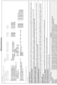
- FIG. 15 is a diagram showing an example of BWP-DownlinkCommon according to this embodiment.
- BWP-DownlinkCommon is information used for setting DL BWP common parameters, and may be included in ServingCellConfigCommon or ServingCellConfigCommonSIB.
- ServingCellConfigCommonSIB is a cell-specific parameter and may be included in SIB1.
- ServingCellConfigCommon is a cell-specific configuration parameter and may be included in other RRC messages.
- BWP-DownlinkCommon may include at least one of the following.
- - genericParameters which is the first initial DL BWP information - pdcch-ConfigCommon, which is information about PDCCH configuration in the first initial DL BWP - pdsch-ConfigCommon, which is information about the configuration of the PDSCH in the first initial DLBWP - genericParametersRedCap, which is the second initial DL BWP information - pdcch-ConfigCommonRedCap, which is information about PDCCH configuration in the second initial DL BWP - pdsch-ConfigCommonRedCap, which is information about the setting of PDSCH in the second initial DL BWP, and additionalSSB-PositionsInBurst, additionalSSB-periodicityServingCell, additional-SS-PBCH-BlockPower, additionalSSB-Frequency, and additionalSSB as second SSB transmission information -
- inOneGroup is information indicating whether or not each SSB in the SSB group is actually transmitted by the value of each corresponding bit. In operation bands below 6 GHz, only information indicated by inOneGroup may be used. Also, in the operation band above 6 GHz, information indicated by inOneGroup and groupPresence may be used.
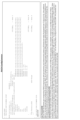
- FIG. 16 is a diagram showing an example of BWP-UplinkCommon according to this embodiment.
- BWP-UplinkCommon is information used to configure UL BWP common parameters, and may be included in ServingCellConfigCommon or ServingCellConfigCommonSIB.
- ServingCellConfigCommonSIB is a cell-specific parameter and may be included in SIB1.
- ServingCellConfigCommon is a cell-specific configuration parameter and may be included in other RRC messages.
- BWP-UplinkCommon may include at least one of the following.
- - genericParameters which is the first initial UL BWP information - rach-ConfigCommon, which is information about the configuration of random access in the first initial UL BWP - pusch-ConfigCommon, which is information about the configuration of PUSCH in the first initial ULBWP - pucch-ConfigCommon, which is information about the configuration of PUCCH in the first initial ULBWP msgA-ConfigCommon, which is information about the transmission of message A in the first initial UL BWP - genericParametersRedCap, which is the second initial UL BWP information - rach-ConfigCommonRedCap, which is information about the configuration of random access in the second initial UL BWP - pusch-ConfigCommonRedCap, which is information about the configuration of PUSCH in the second initial ULBWP - pucch-ConfigCommonRedCap, which is information about the
- FIG. 17 is a diagram showing an example of RACH-ConfigCommon according to this embodiment.
- RACH-ConfigCommon may function as information on the configuration of random access in the first initial UL BWP (that is, rach-ConfigCommon), or information on the configuration of random access in the second initial UL BWP ( That is, it may function as rach-ConfigCommonRedCap).
- push-ConfigCommon may include at least one of the following parameters.
- ssb-perRACH-OccasionAndCB-PreamblesPerSSB which is information indicating the number of first or second SSBs per RO and/or the number of RA preambles per first or second SSB - rsrp-ThresholdSSB, which is information about the RSRP threshold of the first or second SSB
- FIG. 18 is a diagram showing an example of RACH-ConfigCommonTwoStepRA according to this embodiment.
- RACH-ConfigCommonTwoStepRA may serve as information regarding the transmission of message A in the first initial UL BWP (ie msgA-ConfigCommon) or information regarding the transmission of message A in the second initial UL BWP (ie msgA -ConfigCommonRedCap).
- RACH-ConfigCommonTwoStepRA may include at least one of the following parameters.
- msgA-SSB-perRACH-OccasionAndCB-PreamblesPerSSB which is information indicating the number of first or second SSBs per RO and/or the number of RA preambles per first or second SSB - msgA-rsrp-ThresholdSSB, which is information about the RSRP threshold of the first or second SSB
- FIG. 19 is a diagram showing an example of the hardware configuration of each device in the wireless communication system according to this embodiment.
- Each device in the wireless communication system 1 (for example, the terminal 10, the base station 20, the CN 30, etc.) includes a processor 11, a storage device 12, a communication device 13 that performs wired or wireless communication, an input device that receives various input operations, and various It includes an input/output device 14 for outputting information.
- the processor 11 is, for example, a CPU (Central Processing Unit) and controls each device within the wireless communication system 1 .
- the processor 11 may read and execute the program from the storage device 12 to execute various processes described in this embodiment.
- Each device within the wireless communication system 1 may be configured with one or more processors 11 .
- Each device may also be called a computer.
- the storage device 12 is composed of storage such as memory, HDD (Hard Disk Drive) and/or SSD (Solid State Drive).
- the storage device 12 may store various types of information necessary for execution of processing by the processor 11 (for example, programs executed by the processor 11, etc.).
- the communication device 13 is a device that communicates via a wired and/or wireless network, and may include, for example, network cards, communication modules, chips, antennas, and the like. Further, the communication device 13 may include an amplifier, an RF (Radio Frequency) device that performs processing related to radio signals, and a BB (BaseBand) device that performs baseband signal processing.
- RF Radio Frequency
- BB BaseBand
- the RF device for example, performs D/A conversion, modulation, frequency conversion, power amplification, etc. on the digital baseband signal received from the BB device to generate a radio signal to be transmitted from the antenna. Further, the RF device generates a digital baseband signal by performing frequency conversion, demodulation, A/D conversion, etc. on the radio signal received from the antenna, and transmits the digital baseband signal to the BB device.
- the BB device performs processing to convert data into digital baseband signals. Specifically, the BB device may map data to subcarriers, perform IFFT to generate OFDM symbols, insert CPs into the generated OFDM symbols, and generate digital baseband signals. Note that the BB device may apply a transform precoder (DFT spreading) before mapping data to subcarriers.
- DFT spreading transform precoder
- the BB device performs processing to convert the digital baseband signal into data. Specifically, the BB device may remove the CP from the digital baseband signal input from the RF device, perform FFT on the CP-removed signal, and extract the signal in the frequency domain. Note that the BB device may apply IDFT to the signal in the frequency domain.
- the input/output device 14 includes input devices such as keyboards, touch panels, mice and/or microphones, and output devices such as displays and/or speakers.
- Each device in the wireless communication system 1 may omit part of the hardware shown in FIG. 19, or may include hardware not shown in FIG. Also, the hardware shown in FIG. 19 may be configured by one or a plurality of chips.
- FIG. 20 is a diagram showing an example of the functional configuration of a terminal according to this embodiment.
- terminal 10 includes receiver 101 , transmitter 102 , and controller 103 .
- the functional configuration shown in FIG. 20 is merely an example, and any names of functional divisions and functional units may be used as long as the operations according to the present embodiment can be executed.
- the receiving unit 101 and the transmitting unit 102 may be collectively referred to as a communication unit.
- All or part of the functions realized by the receiving unit 101 and the transmitting unit 102 can be realized using the communication device 13. All or part of the functions realized by the receiving unit 101 and the transmitting unit 102 and the control unit 103 can be realized by the processor 11 executing a program stored in the storage device 12 . Also, the program can be stored in a storage medium.
- the storage medium storing the program may be a non-transitory computer readable medium.
- the non-temporary storage medium is not particularly limited, but may be a storage medium such as a USB memory or CD-ROM, for example.
- the receiving unit 101 receives a signal (eg, DL signal and/or sidelink signal). Also, the receiving unit 101 may receive information and/or data transmitted via the signal.
- “receiving” may include, for example, performing processing related to reception such as at least one of receiving, demapping, demodulating, decoding, monitoring, and measuring radio signals.
- the DL signal may include, for example, at least one of PDSCH, PDCCH, downlink reference signal, synchronization signal, PBCH, and the like.
- Receiving section 101 monitors PDCCH candidates in the search space to detect DCI.
- the receiver 101 may receive DL data via PDSCH scheduled using DCI.
- the DL data may include downlink user data and/or higher layer control information (eg, at least one parameter of the MAC layer, RRC layer and Non Access Stratum (NAS) layer).
- the receiver 101 may receive system information via PBCH and/or PDSCH.
- the transmission unit 102 transmits signals (eg, UL signals and/or sidelink signals). Also, the transmitting unit 102 may transmit information and/or data transmitted via the signal. Here, “transmitting” may include performing processing related to transmission, such as at least one of encoding, modulation, mapping, and transmission of radio signals.
- the UL signal may include, for example, at least one of PUSCH, PRACH, PUCCH, uplink reference signals, and the like.
- the transmitting section 102 may transmit UL data via PUSCH scheduled using the DCI received by the receiving section 101 .
- the UL data may transmit uplink user data and/or higher layer control information (eg, at least one parameter of the MAC layer, RRC layer and NAS layer).
- the control unit 103 performs various controls in the terminal 10. Specifically, the control unit 103 controls the operation of the terminal 10 based on information (for example, RRC layer parameters) related to various configurations received by the receiving unit 101 from the base station 20 or another terminal 10. may be controlled.
- information for example, RRC layer parameters
- the operation of the terminal 10 based on the information may be synonymous with "the setting information is configured in the terminal 10".
- the control unit 103 may control signal reception in the receiving unit 101 . Further, the control section 103 may control transmission of signals in the transmission section 102 . The control unit 103 may determine whether to apply the transform precoder to the signal transmitted by the transmission unit 102 .
- the terminal 10 monitors the downlink control channel using a search space (eg, paging search space) in a predetermined period (eg, PDCCH monitoring opportunity), and schedules the downlink shared channel that transmits the paging message.
- a search space eg, paging search space
- a predetermined period eg, PDCCH monitoring opportunity
- the control unit 103 controls transmission of the second synchronization signal block (SSB) in the second initial DL BWP, transmission of the search space in the second initial DL BWP,
- the predetermined period of time may be determined based on configuration and whether conditions relating to at least one of the capabilities of the terminal are met.
- the control unit 103 stores information on the transmission of the second SSB (for example, additional SSB-PositionInBurst) and The predetermined period may be determined based on at least one piece of information (for example, pdcch-ConfigCommonRedCap) regarding configuration of the downlink control channel.
- information on the transmission of the second SSB for example, additional SSB-PositionInBurst
- the predetermined period may be determined based on at least one piece of information (for example, pdcch-ConfigCommonRedCap) regarding configuration of the downlink control channel.
- control section 103 receives information (eg, additional SSB-PositionInBurst) regarding transmission of the second SSB and the second
- the predetermined period may be determined based on at least one piece of information (for example, pdcch-ConfigCommonRedCap) regarding the configuration of the downlink control channel in the initial DL BWP.
- the control unit 103 stores information on the transmission of the first SSB (for example, SSB-PositionInBurst) and The predetermined period may be determined based on at least one piece of information (for example, pdcch-ConfigCommon) regarding configuration of the downlink control channel.
- control section 103 receives information on transmission of the first SSB (for example, SSB-PositionInBurst) and the first The predetermined period may be determined based on at least one piece of information (for example, pdcch-ConfigCommon) regarding the configuration of the downlink control channel in the initial DL BWP.
- the control unit 103 When the second initial DL BWP is not set, the control unit 103 provides information regarding the transmission of the first SSB (for example, SSB-PositionInBurst) and information regarding the setting of the downlink control channel in the first initial DL BWP. (eg, pdcch-ConfigCommon).
- the terminal 10 has a transmission section 102 that transmits a random access preamble, and a second initial downlink bandwidth part (DL BWP) in the cell in which the first initial downlink bandwidth part (DL BWP) is set.
- DL BWP second initial downlink bandwidth part
- the control unit 103 that selects the random access preamble and/or the resource used for transmitting the random access preamble.
- the control unit 103 controls the transmission of the second synchronization signal block (SSB) in the second initial DL BWP, the random access in the second initial DL BWP.
- SSB synchronization signal block
- Search space setting, second random access parameter setting for random access in the second initial DL BWP, and whether or not conditions regarding at least one of the capabilities of the terminal are satisfied, the random access A preamble and/or the resource may be selected.
- the control unit 103 sets the information on the transmission of the second SSB (for example, additional SSB-PositionInBurst), the second random access parameter (for example, the random access preamble and/or the resource may be selected based on at least one of RACH-ConfigCommonRedCap) and received power of the second SSB.
- the information on the transmission of the second SSB for example, additional SSB-PositionInBurst
- the second random access parameter For example, the random access preamble and/or the resource may be selected based on at least one of RACH-ConfigCommonRedCap
- the second random access parameters include information about association of the second SSB with the resource and/or the random access preamble (eg, ssb-perRACH-OccasionAndCB-preamblesPerSSB), and reception of the second SSB. It may include at least one of information on power thresholds (eg, RSRP-ThresholdSSB).
- the control unit 103 transmits information (for example, ssb -PositionsInBurst), a first random access parameter for random access in the first initial DL BWP (for example, Rach-ConfigCommon), and the received power of the first SSB, the random access A preamble and/or the resource may be selected.
- information for example, ssb -PositionsInBurst
- a first random access parameter for random access in the first initial DL BWP for example, Rach-ConfigCommon
- the received power of the first SSB the random access A preamble and/or the resource may be selected.
- the control unit 103 sets information on transmission of the first synchronization signal block (SSB) in the first initial DL BWP (for example, ssb-PositionsInBurst), the first Select the random access preamble and/or the resource based on at least one of the first random access parameter (eg, Rach-ConfigCommon) for random access in the initial DL BWP and the received power of the first SSB You may
- SSB synchronization signal block
- the first random access parameters include information on association between the first SSB and the resource and/or the random access preamble (eg, ssb-perRACH-OccasionAndCB-preamblesPerSSB), and reception of the first SSB. It may include at least one of information on power thresholds (eg, RSRP-ThresholdSSB).
- the terminal 10 includes a receiving section 101 that receives a master information block (MIB), and a second initial downlink bandwidth part (DL BWP) in a cell in which the first initial downlink bandwidth part (DL BWP) is set. and a control unit 103 that controls an operation based on a specific parameter in the MIB based on whether (DL BWP) is set.
- MIB master information block
- DL BWP second initial downlink bandwidth part
- control unit 103 that controls an operation based on a specific parameter in the MIB based on whether (DL BWP) is set.
- the control unit 103 transmits the second synchronization signal block (SSB) at the second initial DL BWP and searches for paging at the second initial DL BWP.
- SSB second synchronization signal block
- control unit 103 converts the specific parameter in the MIB received via the broadcast channel included in the second SSB to It may be ignored or assumed that said particular parameter is not transmitted.
- the specific parameters include information on whether a cell is barred (eg, cellBarred), information on intra-frequency cell selection and/or reselection (eg, intraFreqReselection), and the second SSB and resource block. At least one of information about the frequency domain offset to/from the grid (eg, ssb-SubcarrierOffset) may be included.
- the control unit 103 may interpret it to have a specific meaning regardless of the value of the specific parameter.
- the specific parameter may include information on whether or not a cell is barred (eg, cellBarred), and the control unit 103 may interpret that the cell is not barred regardless of the value indicated by the information.
- FIG. 21 is a diagram showing an example of the functional block configuration of the base station according to this embodiment.
- the base station 20 includes a receiver 201, a transmitter 202, and a controller 203.
- FIG. The functional configuration shown in FIG. 21 is merely an example, and any names of functional divisions and functional units may be used as long as the operations according to the present embodiment can be executed.
- the receiving unit 201 and the transmitting unit 202 may be collectively referred to as a communication unit.
- All or part of the functions realized by the receiving unit 201 and the transmitting unit 202 can be realized using the communication device 13. All or part of the functions realized by the receiving unit 201 and the transmitting unit 202 and the control unit 203 can be realized by the processor 11 executing a program stored in the storage device 12 . Also, the program can be stored in a storage medium.
- the storage medium storing the program may be a computer-readable non-temporary storage medium.
- the non-temporary storage medium is not particularly limited, but may be a storage medium such as a USB memory or CD-ROM, for example.
- the receiving unit 201 receives signals (eg, UL signals and/or sidelink signals). Also, the receiving unit 201 may receive information and/or data (for example, the UL data described above) transmitted via the signal.
- signals eg, UL signals and/or sidelink signals.
- the receiving unit 201 may receive information and/or data (for example, the UL data described above) transmitted via the signal.
- the transmission unit 202 transmits signals (eg, DL signals and/or sidelink signals). Also, the transmitting unit 202 may transmit information and/or data (for example, the DL data described above) transmitted via the signal. Part of the information transmitted from the transmission unit 202 may be transmitted by a transmission unit within the core network device.
- signals eg, DL signals and/or sidelink signals.
- the transmitting unit 202 may transmit information and/or data (for example, the DL data described above) transmitted via the signal. Part of the information transmitted from the transmission unit 202 may be transmitted by a transmission unit within the core network device.
- the control unit 203 performs various controls for communication with the terminal 10. Specifically, the control unit 203 may determine information regarding various settings to be notified to the terminal 10 . Transmitting the information to the terminal 10 may be synonymous with "setting the information in the terminal".
- the control unit 203 may control signal reception in the receiving unit 201 .
- the control unit 203 may also control signal transmission in the transmission unit 202 .
- the base station 20 monitors the downlink control channel using a search space (eg, paging search space) in a predetermined period (eg, PDCCH monitoring opportunity), and schedules a downlink shared channel for transmitting paging messages.
- a search space eg, paging search space
- a predetermined period eg, PDCCH monitoring opportunity
- the base station 20 based on the receiving unit 201 that receives a random access preamble, the random access preamble and/or the resources used for receiving the random access preamble, the transmission of the DL signal and / Alternatively, it may include a control unit 203 that controls reception of the UL signal.
- the control unit 203 may estimate the pseudo collocation (QCL) relationship for the terminal 10 based on the random access preamble and/or the synchronization signal block (SSB) associated with the random access preamble.
- the control unit 203 may control transmission of DL signals and/or reception of UL signals using the same beam as the SSB.
- the base station 20 includes a transmission section 202 that transmits a master information block (MIB), and a second initial downlink bandwidth part (DL BWP) within a cell in which the first initial downlink bandwidth part (DL BWP) is set. and a control unit 203 that controls transmission of specific parameters in the MIB based on whether or not the part (DL BWP) is set.
- MIB master information block
- DL BWP second initial downlink bandwidth part
- control unit 203 that controls transmission of specific parameters in the MIB based on whether or not the part (DL BWP) is set.
- the control unit 203 transmits the second synchronization signal block (SSB) at the second initial DL BWP and searches for paging at the second initial DL BWP.
- SSB second synchronization signal block
- transmission of the specific parameter in the MIB over the broadcast channel provided by the MIB may be discontinued.
- the control unit 203 stops transmission of the specific parameter in the MIB via the broadcast channel included in the second SSB. You may
- Various signals, information and parameters in the above embodiments may be signaled in any layer. That is, the various signals, information, and parameters are replaced with signals, information, and parameters of any layer such as higher layers (eg, NAS layer, RRC layer, MAC layer, etc.), lower layers (eg, physical layer), etc. good too. Further, the notification of the predetermined information is not limited to being performed explicitly, but may be performed implicitly (for example, by not notifying the information or using other information).
- a slot may be named any unit of time having a predetermined number of symbols.
- RB may be any name as long as it is a frequency unit having a predetermined number of subcarriers. Also, the "first .
- a physical channel that transmits DL data a physical channel that transmits UL data
- a physical channel that transmits DCI a physical channel that transmits broadcast information
- a physical channel that transmits RA preambles PDSCH, PUSCH, PDCCH, PBCH, and PRACH are exemplified, respectively, but the names are not limited to these as long as the physical channels have similar functions.
- These physical channels may also be translated into transport channels to which physical channels are mapped.
- PDSCH, PUSCH, PDCCH, PBCH and PRACH etc.
- DL-SCH downlink shared channel
- Uplink Shared Channel: UL -SCH uplink shared channel
- RCH Random Access Channel
- DL data and UL data are downlink and uplink data, respectively, and the data includes user data and higher layer control information (e.g., RRC parameters, medium access control (Medium Access Control: MAC) parameters, etc.).
- RRC Radio Resource Control
- the use of the terminal 10 in the above embodiment is not limited to those illustrated, as long as it has similar functions, any use (for example, eMBB, URLLC, Device-to- Device (D2D), Vehicle-to-Everything (V2X), etc.).
- the format of various information is not limited to the above embodiment, and may be appropriately changed to bit representation (0 or 1), true/false value (Boolean: true or false), integer value, character, or the like.
- singularity and plurality in the above embodiments may be interchanged.
Landscapes
- Engineering & Computer Science (AREA)
- Computer Networks & Wireless Communication (AREA)
- Signal Processing (AREA)
- Mobile Radio Communication Systems (AREA)
Abstract
Description
本開示は、ランダムアクセスに関する動作を適切に制御可能な端末及び無線通信方法を提供することを目的の一つとする。
SSBは、同期信号、PBCH及びPBCHの復調用参照信号(Demodulation Reference Signal:DM-RS)の少なくとも一つを含むブロックである。SSBは、SS/PBCHブロック、SSブロック等とも呼ばれてもよい。
一つのセルCに対して、一つ又は複数の帯域幅部分(Bandwidth Part:BWP)が設定されてもよい。BWPは、DL用のBWP(以下、「DL BWP」という)、及び/又は、UL用のBWP(以下、「UL BWP」という)を含んでもよい。また、BWPは、セル固有に設定されるBWP(以下、「初期BWP(initial BWP)」という)と、端末10固有に設定されるBWP(以下、「個別BWP(dedicated BWP)」という)と、を含んでもよい。初期BWPは、初期アクセスに用いられ、及び/又は、一以上の端末10に共通であってもよい。初期BWPは、DL用の初期BWP(以下、「初期DL BWP」という)と、UL用の初期BWP(以下、「初期UL BWP」という)とを含んでもよい。個別BWPは、「UE固有(UE-specific)BWP」とも呼ばれる。
端末10は、3GPPのリリース15又は16でサポートされる既存端末よりも低い性能や価格帯を想定したRedCap端末であってもよい。RedCap端末は、例えば、産業用無線センサ(industrial wireless sensor)、監視カメラ(video serveilance)、ウエアラブルデバイス(wearable device)等に利用されることが想定されている。例えば、RedCap端末がサポートする最大帯域幅は、既存端末の最大帯域幅よりも狭くてもよい。
本実施形態におけるSSBに基づく動作(1)~(3)のための端末10の設定(configuration)について説明する。端末10は、基地局20からパラメータ又は情報を受信する。本実施形態において「設定される(configured)」とは、当該パラメータ及び/又は情報を受信することであってもよいし、受信したパラメータ及び/又は情報に基づいて端末10の動作を制御することであってもよい。以下では、当該パラメータ及び/又は情報として、RRCパラメータを例示するが、これに限られない。当該パラメータ及び/又は情報は、上位レイヤ(例えば、媒体アクセス制御(Medium Access Control:MAC)レイヤ、非アクセスストレイタム(Non Access Stratum:NAS)レイヤ等の物理レイヤよりも上位レイヤ)のパラメータであってもよいし、物理レイヤのパラメータであってもよい。
本実施形態において、第1の初期DL BWPは、基地局20からの上記第1の初期DL BWP情報に基づいて、端末10に設定されてもよい。ここで、第1の初期DL BWP情報は、上記locationAndBandwidth、subcarrierSpacing及びcyclicPrefixの少なくとも一つを含んでもよい。また、第1の初期DL BWP情報は、SIB1内のRRCパラメータ(例えば、「ServingCellConfigCommonSIB」内の「DownlinkConfigCommonSIB」内の「initialDownlinkBWP」としての「BWP-DownlinkCommon」内の「genericParameters」としての「BWP」)であってもよい。又は、第1の初期DL BWP情報は、他のRRCメッセージ内のRRCパラメータ(例えば、「ServingCellConfigCommon」内の「DownlinkConfigCommon」内の「initialDownlinkBWP」としての「BWP-DownlinkCommon」内の「genericParameters」としての「BWP」)であってもよい。第1の初期DL BWP情報は、セル固有であってもよい。
第1の初期UL BWPは、基地局20からの上記第1の初期UL BWP情報に基づいて、端末10に設定されてもよい。ここで、第1の初期DL BWP情報は、上記locationAndBandwidth、subcarrierSpacing及びcyclicPrefixの少なくとも一つを含んでもよい。また、第1の初期UL BWP情報は、SIB1内のRRCパラメータ(例えば、「ServingCellConfigCommonSIB」内の「UplinkConfigCommonSIB」内の「initialUplinkBWP」としての「BWP-UplinkCommon」内の「genericParameters」としての「BWP」)であってもよい。又は、第1の初期UL BWP情報は、他のRRCメッセージ内のRRCパラメータ(例えば、「ServingCellConfigCommon」内の「UplinkConfigCommon」内の「initialUplinkBWP」としての「BWP-UplinkCommon」内の「genericParameters」としての「BWP」)であってもよい。第2の初期UL BWP情報は、セル固有であってもよい。
第1のSSBは、第1のSSBの送信に関する情報(以下、「第1のSSB送信情報」という)に基づいて、端末10に設定されてもよい。第1のSSB送信情報は、SSバーストセット内での第1のSSB送信に関する情報(以下、「ssb-PositionsInBurst」という)、第1のSSBのSSB周期に関する情報(以下、「ssb-periodicityServingCell」という)、第1のSSBの送信電力に関する情報(以下、「ss-PBCH-BlockPower」という)、第1のSSBの送信周波数に関する情報(以下、「ssb-Frequency」という)、及び、第1のSSBのメジャメントタイミングに関する情報(以下、「SSB-MTC」という)の少なくとも一つを含んでもよい。第1のSSB送信情報は、SIB1内のRRCパラメータ(例えば、「ServingCellConfigCommonSIB」内のパラメータ)であってもよいし、他のRRCメッセージ内のRRCパラメータ(例えば、「ServingCellConfigCommon」内のパラメータ)であってもよい。第1のSSB送信情報は、セル固有であってもよい。
第1の初期DL BWPにおけるPDCCHの設定に関する情報(以下、「pdcch-ConfigCommon」という)が端末10に設定されてもよい。pdcch-ConfigCommonは、ページングサーチスペースに関する情報(以下、「pagingSearchSpace」という)、RAサーチスペースに関する情報(以下、「ra-SearchSpace」という)、CORESETに関する情報(以下、「commonControlResourceSet」という)、及び、ページング機会(paging occasion:PO)内の最初のPDCCHモニタリング機会に関する情報(以下、「firstPDCCH-MonitoringOccasionOfPO」という)の少なくとも一つを含んでもよい。pdcch-ConfigCommonは、SIB1内のRRCパラメータ(例えば、「ServingCellConfigCommonSIB」内の「DownlinkConfigCommonSIB」内の「initialDownlinkBWP」としての「BWP-DownlinkCommon」内のパラメータ)であってもよい。又は、pdcch-ConfigCommonは、他のRRCメッセージ内のRRCパラメータ(例えば、「ServingCellConfigCommon」内の「DownlinkConfigCommon」内の「initialDownlinkBWP」としての「BWP-DownlinkCommon」内のパラメータ)であってもよい。pdcch-ConfigCommonは、セル固有であってもよい。pdcch-ConfigCommonは、第1の下り制御チャネル設定情報等と呼ばれてもよい。
第1の初期DL BWPにおけるランダムアクセスの設定に関する情報(以下、「rach-ConfigCommon」という)が端末10に設定されてもよい。rach-ConfigCommonは、ROあたりの第1のSSBの数、及び/又は、第1のSSB送信あたりのRAプリアンブルの数を示す情報(以下、「ssb-perRACH-OccasionAndCB-PreamblesPerSSB」という)、及び、第1のSSBの受信電力(例えば、RSRP)の閾値に関する情報(以下、「rsrp-ThresholdSSB」という)の少なくとも一つを含んでもよい。rach-ConfigCommonは、SIB1内のRRCパラメータ(例えば、「ServingCellConfigCommonSIB」内の「UplinkConfigCommonSIB」内の「initialUplinkBWP」としての「BWP-UplinkCommon」内のパラメータ)であってもよい。又は、rach-ConfigCommonは、他のRRCメッセージ内のRRCパラメータ(例えば、「ServingCellConfigCommon」内の「UplinkConfigCommon」内の「initialUplinkBWP」としての「BWP-UplinkCommon」内のパラメータ)であってもよい。rach-ConfigCommonは、セル固有であってもよい。rach-ConfigCommonは、第1のランダムアクセスパラメータ等と呼ばれてもよい。
第1の初期DL BWPにおけるページングの設定に関する情報(以下、「PCCH-Config」という)が端末10に設定されてもよい。PCCH-Configは、ページングサイクルに関する情報(以下、「PagingCycle」という)、firstPDCCH-MonitoringOccasionOfPO、ページングサイクル内のページングフレーム(paging frmae:PF)の数及び/又は時間オフセットを示す情報(以下、「nAndPagingFrameOffset」という)、PFあたりのPOの数に関する情報(以下、「ns」という)、及び、PO内のSSBあたりのPDCCHモニタリング機会の数に関する情報(以下、「nrofPDCCH-MonitoringOccasionPerSSB-InPO」という)の少なくとも一つを含んでもよい。PCCH-Configは、SIB1内のRRCパラメータ(例えば、「ServingCellConfigCommonSIB」内の「DownlinkConfigCommonSIB」内のパラメータ)であってもよい。PCCH-Configは、セル固有であってもよい。PCCH-Configは、第1のページング設定情報等と呼ばれてもよい。
(1)ページング用のPDCCHモニタリング機会の決定動作
端末10は、PDCCHモニタリング機会においてPDCCHをモニタリングして、ページングメッセージを伝送するPDSCHのスケジューリングに用いられるDCIを受信する。当該DCIは、特定のRNTI(例えば、Paging(P)-RNTI)によりCRCスクランブルされてもよい。端末10は、第1の初期DL BWPが設定されるセルC内に第2の初期DL BWPが設定されるか否かに基づいて、PDCCHモニタリング機会を決定してもよい。
(式1)
(SFN+PF_offset) mod T
= (T div N)*(UE_ID mod N)
ここで、TはDRX周期であり、NはT内のPFの数であり、PF_offsetは所定のオフセットであり、UE_IDは端末10の識別子(例えば、5G-S-TMSI)に基づいて決定される値である。Tは、上記PagingCycleに基づいて決定されてもよい。PagingCycleは、例えば、32、64、128又は256RFを示してもよい。また、N及び/又はPF_offsetは、上記nAndPagingFrameOffsetに基づいて決定されてもよい。nAndPagingFrameOffsetは、T内のxRF毎にPFが配置されること(例えば、x=1、2、4、8又は16)及び/又は時間オフセットを示してもよい。
(a)第2の初期DL BWPにおける第2のSSBの送信が設定される。
(b)第2の初期DL BWPにおいてページングサーチスペースが設定される。
(c)端末10が特定の能力を有すること。
ランダムアクセス手順において、端末10は、RAプリアンブルを送信する。端末10は、第1の初期DL BWPが設定されるセルC内に第2の初期DL BWPが設定されるか否かに基づいて、RAプリアンブル及び/又はRAプリアンブルの送信に用いられるROを決定してもよい。
(A)第2の初期DL BWPにおける第2のSSBの送信が設定される。
(B)第2の初期DL BWPにおいてRAサーチスペースが設定される。
(C)第2のランダムアクセスパラメータが設定される。
(D)端末10が特定の能力を有する。
端末10は、PBCHを介して、MIBを受信する。端末10は、第1の初期DL BWPが設定されるセルC内に第2の初期DL BWPが設定されるか否かに基づいて、MIB受信時の動作を制御してもよい。具体的には、端末10は、第2の初期DL BWPが設定される場合、端末10は、第2の初期DL BWPで送信されるSSB内のPBCHを介して受信されたMIB内の特定のパラメータを無視する、又は、当該特定のパラメータが送信されないと想定してもよい。
・SFNに関する情報(以下、「systemFrameNumber」という)
・サブキャリア間隔に関する情報(以下、「subCarrierSpacingCommon」という)
・SSBとリソースブロックグリッドとの間の周波数オフセット(kSSB)に関する情報(以下、「ssb-SubcarrierOffset」という)
・DM-RSの位置に関する情報(以下、「dmrs-TypeA-Position」という)
・共通CORESET(CORESET#0)及び/又は共通サーチスペース(サーチスペース#0)に関する情報(以下、「pdcch-ConfigSIB1」という)
・セル(に対するキャンプオン)が禁止されるか否かに関する情報(以下、「cellBarred」という)
・同周波数セルの選択及び/又は再選択に関する情報(以下、「intraFreqReselection」という)
(i)第2の初期DL BWPにおける第2のSSBの送信が設定される。
(ii)第2の初期DL BWPにおいてページングサーチスペースが設定される。
(iii)第2の初期DL BWにおいてRAサーチスペースが設定される。
(iv)端末10が特定の能力を有する。
例えば、上記条件(i)、(ii)及び(iv)は、上記条件(a)、(b)及び(c)と同様である。上記条件(iii)は、上記条件(B)と同様である。
図15~18を参照し、本実施形態における上記SSBに基づく動作(1)~(3)のための端末10の設定に用いられる上記パラメータ又は情報の一例を説明する。なお、図15~18に示す各パラメータ又は情報は、例示にすぎず、名称、サイズ、階層構造等は図示するものに限られない。また、本実施形態における上記動作(1)~(3)には、図15~18に図示しないパラメータ又は情報が用いられてもよいことは勿論である。
・上記第1の初期DL BWP情報であるgenericParameters
・第1の初期DL BWPにおけるPDCCHの設定に関する情報であるpdcch-ConfigCommon
・第1の初期DLBWPにおけるPDSCHの設定に関する情報であるpdsch-ConfigCommon
・上記第2の初期DL BWP情報であるgenericParametersRedCap
・第2の初期DL BWPにおけるPDCCHの設定に関する情報であるpdcch-ConfigCommonRedCap
・第2の初期DL BWPにおけるPDSCHの設定に関する情報であるpdsch-ConfigCommonRedCap、及び、第2のSSB送信情報としてのadditionalSSB-PositionsInBurst、additionalSSB-periodicityServingCell、additional-SS-PBCH-BlockPower、additionalSSB-Frequency及びadditionalSSB-SMTCの少なくとも一つ
なお、additionalSSB-PositionsInBurst内のgroupPresenceは、SSバーストセット内で最大64個送信可能なSSBを8つのSSBグループに分割したとき、各SSBグループが実際に送信されるか否かを、対応する各ビットの値によって示す情報である。また、inOneGroupは、SSBグループ内の各SSBが実際に送信されるか否かを、対応する各ビットの値によって示す情報である。6GHzを下回るオペレーションバンドでは、inOneGroupが示す情報のみが用いられてもよい。また、6GHzを上回るオペレーションバンドでは、inOneGroup及びgroupPresenceが示す情報が用いられてもよい。
・上記第1の初期UL BWP情報であるgenericParameters
・第1の初期UL BWPにおけるランダムアクセスの設定に関する情報であるrach-ConfigCommon
・第1の初期ULBWPにおけるPUSCHの設定に関する情報であるpusch-ConfigCommon
・第1の初期ULBWPにおけるPUCCHの設定に関する情報であるpucch-ConfigCommon
・第1の初期UL BWPにおけるメッセージAの送信に関する情報であるmsgA-ConfigCommon
・上記第2の初期UL BWP情報であるgenericParametersRedCap
・第2の初期UL BWPにおけるランダムアクセスの設定に関する情報であるrach-ConfigCommonRedCap
・第2の初期ULBWPにおけるPUSCHの設定に関する情報であるpusch-ConfigCommonRedCap
・第2の初期ULBWPにおけるPUCCHの設定に関する情報であるpucch-ConfigCommonRedCap
・第2の初期UL BWPにおけるメッセージAの送信に関する情報であるmsgA-ConfigCommonRedCap
・ROあたりの第1又は第2のSSBの数、及び/又は、第1又は第2のSSBあたりのRAプリアンブルの数を示す情報であるssb-perRACH-OccasionAndCB-PreamblesPerSSB
・第1又は第2のSSBのRSRPの閾値に関する情報であるrsrp-ThresholdSSB
・ROあたりの第1又は第2のSSBの数、及び/又は、第1又は第2のSSBあたりのRAプリアンブルの数を示す情報であるmsgA-SSB-perRACH-OccasionAndCB-PreamblesPerSSB
・第1又は第2のSSBのRSRPの閾値に関する情報であるmsgA-rsrp-ThresholdSSB
次に、以上のような無線通信システム1の各装置の構成について説明する。なお、以下の構成は、本実施形態の説明において必要な構成を示すためのものであり、各装置が図示以外の機能ブロックを備えることを排除するものではない。
図19は、本実施形態に係る無線通信システム内の各装置のハードウェア構成の一例を示す図である。無線通信システム1内の各装置(例えば、端末10、基地局20、CN30など)は、プロセッサ11、記憶装置12、有線又は無線通信を行う通信装置13、各種の入力操作を受け付ける入力装置や各種情報の出力を行う入出力装置14を含む。
≪端末≫
図20は、本実施形態に係る端末の機能構成の一例を示す図である。図20に示すように、端末10は、受信部101と、送信部102と、制御部103と、を備える。図20に示す機能構成は一例にすぎず、本実施形態に係る動作を実行できるのであれば、機能区分及び機能部の名称はどのようなものでもよい。また、受信部101と送信部102とをまとめて通信部と称してもよい。
図21は、本実施形態に係る基地局の機能ブロック構成の一例を示す図である。図21に示すように、基地局20は、受信部201と、送信部202と、制御部203と、を備える。図21に示す機能構成は一例にすぎず、本実施形態に係る動作を実行できるのであれば、機能区分及び機能部の名称はどのようなものでもよい。また、受信部201と送信部202とをまとめて通信部と称してもよい。
上記実施形態における各種の信号、情報、パラメータは、どのようなレイヤでシグナリングされてもよい。すなわち、上記各種の信号、情報、パラメータは、上位レイヤ(例えば、NASレイヤ、RRCレイヤ、MACレイヤ等)、下位レイヤ(例えば、物理レイヤ)等のどのレイヤの信号、情報、パラメータに置き換えられてもよい。また、所定情報の通知は明示的に行うものに限られず、黙示的に(例えば、情報を通知しないことや他の情報を用いることによって)行われてもよい。
Claims (16)
- 無線リソース制御メッセージに含まれる第1の同期信号及び物理報知チャネル(SS/PBCH)ブロックの送信に関する情報に基づいて、第1のSS/PBCHブロックを受信し、
前記無線リソース制御メッセージに第2のSS/PBCHブロックの送信に関する情報が含まれる場合、当該第2のSS/PBCHブロックの送信に関する情報に基づいて、前記第2のSS/PBCHブロックを受信する受信部と、
前記第2のSS/PBCHブロックを前記受信部により受信した場合、当該第2のSS/PBCHブロックに基づいて、衝突フリーランダムアクセス手順におけるランダムアクセス機会を選択する制御部と、を備える
端末。 - 前記第2のSS/PBCHブロックの送信に関する情報は、前記第2のSS/PBCHブロックの周波数に関する情報を含む
請求項1に記載の端末。 - 前記第1のSS/PBCHブロックはセルデファイニングSS/PBCHブロックであり、前記第2のSS/PBCHブロックは非セルデファイニングSS/PBCHブロックである
請求項1又は請求項2に記載の端末。 - 前記受信部は、前記第2のSS/PBCHブロックを、RedCap端末向けの初期下りリンク帯域幅部分において受信する
請求項1から請求項3のいずれかに記載の端末。 - 無線リソース制御メッセージを送信し、
前記無線リソース制御メッセージに含めた第1の同期信号及び物理報知チャネル(SS/PBCH)ブロックの送信に関する情報に基づいて、第1のSS/PBCHブロックを送信し、
前記無線リソース制御メッセージに含めた第2のSS/PBCHブロックの送信に関する情報に基づいて、前記第2のSS/PBCHブロックを送信する送信部と、
前記第2のSS/PBCHブロックを送信する場合に、当該第2のSS/PBCHブロックに基づいて、衝突フリーランダムアクセス手順におけるランダムアクセス機会を選択する制御部と、を備える
基地局。 - 前記第2のSS/PBCHブロックの送信に関する情報は、前記第2のSS/PBCHブロックの周波数に関する情報を含む
請求項5に記載の基地局。 - 前記第1のSS/PBCHブロックはセルデファイニングSS/PBCHブロックであり、前記第2のSS/PBCHブロックは非セルデファイニングSS/PBCHブロックである
請求項5又は請求項6に記載の基地局。 - 前記送信部は、前記第2のSS/PBCHブロックを、RedCap端末向けの初期下りリンク帯域幅部分において送信する
請求項5から請求項7のいずれかに記載の基地局。 - 無線リソース制御メッセージに含まれる第1の同期信号及び物理報知チャネル(SS/PBCH)ブロックの送信に関する情報に基づいて、第1のSS/PBCHブロックを受信し、
前記無線リソース制御メッセージに第2のSS/PBCHブロックの送信に関する情報が含まれる場合、当該第2のSS/PBCHブロックの送信に関する情報に基づいて、前記第2のSS/PBCHブロックを受信し、
前記第2のSS/PBCHブロックを受信した場合、当該第2のSS/PBCHブロックに基づいて、衝突フリーランダムアクセス手順におけるランダムアクセス機会を選択する
端末の無線通信方法。 - 前記第2のSS/PBCHブロックの送信に関する情報は、前記第2のSS/PBCHブロックの周波数に関する情報を含む
請求項9に記載の端末の無線通信方法。 - 前記第1のSS/PBCHブロックはセルデファイニングSS/PBCHブロックであり、前記第2のSS/PBCHブロックは非セルデファイニングSS/PBCHブロックである
請求項9又は請求項10に記載の端末の無線通信方法。 - 前記端末は、前記第2のSS/PBCHブロックを、RedCap端末向けの初期下りリンク帯域幅部分において受信する
請求項9から請求項11のいずれかに記載の端末の無線通信方法。 - 無線リソース制御メッセージを送信し、
前記無線リソース制御メッセージに含まれる第1の同期信号及び物理報知チャネル(SS/PBCH)ブロックの送信に関する情報に基づいて、第1のSS/PBCHブロックを送信し、
前記無線リソース制御メッセージに含まれる第2のSS/PBCHブロックの送信に関する情報に基づいて、前記第2のSS/PBCHブロックを送信し、
前記第2のSS/PBCHブロックを送信した場合、当該第2のSS/PBCHブロックに基づいて、衝突フリーランダムアクセス手順におけるランダムアクセス機会を選択する
基地局の無線通信方法。 - 前記第2のSS/PBCHブロックの送信に関する情報は、前記第2のSS/PBCHブロックの周波数に関する情報を含む
請求項13に記載の基地局の無線通信方法。 - 前記第1のSS/PBCHブロックはセルデファイニングSS/PBCHブロックであり、前記第2のSS/PBCHブロックは非セルデファイニングSS/PBCHブロックである
請求項13又は請求項14に記載の無線通信方法。 - 前記基地局は、前記第2のSS/PBCHブロックを、RedCap端末向けの初期下りリンク帯域幅部分において送信する
請求項13から請求項15のいずれかに記載の無線通信方法。
Priority Applications (1)
| Application Number | Priority Date | Filing Date | Title |
|---|---|---|---|
| CN202280062454.4A CN117957906A (zh) | 2021-09-30 | 2022-09-30 | 终端、基站以及无线通信方法 |
Applications Claiming Priority (2)
| Application Number | Priority Date | Filing Date | Title |
|---|---|---|---|
| JP2021-162297 | 2021-09-30 | ||
| JP2021162297 | 2021-09-30 |
Publications (1)
| Publication Number | Publication Date |
|---|---|
| WO2023054685A1 true WO2023054685A1 (ja) | 2023-04-06 |
Family
ID=85783009
Family Applications (1)
| Application Number | Title | Priority Date | Filing Date |
|---|---|---|---|
| PCT/JP2022/036745 WO2023054685A1 (ja) | 2021-09-30 | 2022-09-30 | 端末、基地局、及び無線通信方法 |
Country Status (2)
| Country | Link |
|---|---|
| CN (1) | CN117957906A (ja) |
| WO (1) | WO2023054685A1 (ja) |
-
2022
- 2022-09-30 WO PCT/JP2022/036745 patent/WO2023054685A1/ja active Application Filing
- 2022-09-30 CN CN202280062454.4A patent/CN117957906A/zh active Pending
Non-Patent Citations (2)
| Title |
|---|
| MODERATOR (ERICSSON): "FL summary #5 on reduced maximum UE bandwidth for RedCap", 3GPP DRAFT; R1-2108497, 3RD GENERATION PARTNERSHIP PROJECT (3GPP), MOBILE COMPETENCE CENTRE ; 650, ROUTE DES LUCIOLES ; F-06921 SOPHIA-ANTIPOLIS CEDEX ; FRANCE, vol. RAN WG1, no. e-Meeting; 20210816 - 20210827, 26 August 2021 (2021-08-26), Mobile Competence Centre ; 650, route des Lucioles ; F-06921 Sophia-Antipolis Cedex ; France , XP052042783 * |
| NORDIC SEMICONDUCTOR ASA: "On aspects related to reduced maximum UE BW", 3GPP DRAFT; R1-2107040, 3RD GENERATION PARTNERSHIP PROJECT (3GPP), MOBILE COMPETENCE CENTRE ; 650, ROUTE DES LUCIOLES ; F-06921 SOPHIA-ANTIPOLIS CEDEX ; FRANCE, vol. RAN WG1, no. e-Meeting; 20210816 - 20210827, 6 August 2021 (2021-08-06), Mobile Competence Centre ; 650, route des Lucioles ; F-06921 Sophia-Antipolis Cedex ; France , XP052033370 * |
Also Published As
| Publication number | Publication date |
|---|---|
| CN117957906A (zh) | 2024-04-30 |
Similar Documents
| Publication | Publication Date | Title |
|---|---|---|
| RU2731677C1 (ru) | Способ конфигурирования формы сигнала передачи восходящей линии связи, базовая станция и пользовательское оборудование | |
| KR102624966B1 (ko) | 비면허 스펙트럼에서의 rach 절차 | |
| JP7010933B2 (ja) | 無線通信システムにおいてリソースを選択しpscchを伝送する方法及び装置 | |
| KR102401700B1 (ko) | 빔포밍 시스템의 새로운 무선 랜 액세스 | |
| CN110621068B (zh) | 一种寻呼方法和装置 | |
| US10064064B2 (en) | LTE-U communication devices and methods for aperiodic beacon and reference signal transmission | |
| EP2868142B1 (en) | Sounding reference signal (srs) mechanism for intracell device-to-device (d2d) communication | |
| US11889490B2 (en) | Data and control channels in synchronization bursts for millimeter wave new radio | |
| US20190037606A1 (en) | User terminal, radio base station and radio communication method | |
| US20180132273A1 (en) | Random access response message transmission | |
| JP2019537896A (ja) | ピーク対平均電力比低減のための同期信号送信技法 | |
| US10419185B2 (en) | System and method for listen before talk-based random access with partial subframes | |
| EP3780858A1 (en) | User device | |
| US20160135056A1 (en) | Device of Handling Measurement Signal on Unlicensed Carrier | |
| US20160135145A1 (en) | Telecommunications apparatus and method relating to a random access procedure | |
| JP6348997B2 (ja) | 免許不要帯域における空きチャネル判定及び伝送を扱うための装置 | |
| US11291044B2 (en) | Apparatuses and methods for preamble sequence management for contention based access | |
| WO2023054685A1 (ja) | 端末、基地局、及び無線通信方法 | |
| WO2023054684A1 (ja) | 端末、基地局、及び無線通信方法 | |
| WO2023054686A1 (ja) | 端末、基地局、及び無線通信方法 | |
| WO2017170774A1 (ja) | ユーザ装置、基地局、及び報知情報受信方法 | |
| CN114175777A (zh) | 通信方法、设备及其计算机可读介质 | |
| WO2023153340A1 (ja) | 端末、基地局及び無線通信方法 | |
| WO2023132325A1 (ja) | 端末、基地局及び通信方法 | |
| US11864246B2 (en) | Method and apparatus for random access |
Legal Events
| Date | Code | Title | Description |
|---|---|---|---|
| 121 | Ep: the epo has been informed by wipo that ep was designated in this application |
Ref document number: 22876547 Country of ref document: EP Kind code of ref document: A1 |
|
| WWE | Wipo information: entry into national phase |
Ref document number: 2023551908 Country of ref document: JP |
|
| REG | Reference to national code |
Ref country code: BR Ref legal event code: B01A Ref document number: 112024005727 Country of ref document: BR |
|
| ENP | Entry into the national phase |
Ref document number: 2022876547 Country of ref document: EP Effective date: 20240430 |