WO2023054645A1 - 情報処理装置、情報処理方法及び情報処理プログラム - Google Patents
情報処理装置、情報処理方法及び情報処理プログラム Download PDFInfo
- Publication number
- WO2023054645A1 WO2023054645A1 PCT/JP2022/036597 JP2022036597W WO2023054645A1 WO 2023054645 A1 WO2023054645 A1 WO 2023054645A1 JP 2022036597 W JP2022036597 W JP 2022036597W WO 2023054645 A1 WO2023054645 A1 WO 2023054645A1
- Authority
- WO
- WIPO (PCT)
- Prior art keywords
- information processing
- element information
- graph structure
- nodes
- information
- Prior art date
- Legal status (The legal status is an assumption and is not a legal conclusion. Google has not performed a legal analysis and makes no representation as to the accuracy of the status listed.)
- Ceased
Links
Images









Classifications
-
- G—PHYSICS
- G06—COMPUTING OR CALCULATING; COUNTING
- G06F—ELECTRIC DIGITAL DATA PROCESSING
- G06F40/00—Handling natural language data
- G06F40/10—Text processing
- G06F40/166—Editing, e.g. inserting or deleting
-
- G—PHYSICS
- G06—COMPUTING OR CALCULATING; COUNTING
- G06F—ELECTRIC DIGITAL DATA PROCESSING
- G06F40/00—Handling natural language data
- G06F40/40—Processing or translation of natural language
- G06F40/55—Rule-based translation
- G06F40/56—Natural language generation
-
- G—PHYSICS
- G06—COMPUTING OR CALCULATING; COUNTING
- G06T—IMAGE DATA PROCESSING OR GENERATION, IN GENERAL
- G06T7/00—Image analysis
- G06T7/0002—Inspection of images, e.g. flaw detection
- G06T7/0012—Biomedical image inspection
-
- G—PHYSICS
- G06—COMPUTING OR CALCULATING; COUNTING
- G06V—IMAGE OR VIDEO RECOGNITION OR UNDERSTANDING
- G06V10/00—Arrangements for image or video recognition or understanding
- G06V10/20—Image preprocessing
- G06V10/25—Determination of region of interest [ROI] or a volume of interest [VOI]
-
- G—PHYSICS
- G06—COMPUTING OR CALCULATING; COUNTING
- G06V—IMAGE OR VIDEO RECOGNITION OR UNDERSTANDING
- G06V10/00—Arrangements for image or video recognition or understanding
- G06V10/70—Arrangements for image or video recognition or understanding using pattern recognition or machine learning
- G06V10/82—Arrangements for image or video recognition or understanding using pattern recognition or machine learning using neural networks
-
- G—PHYSICS
- G16—INFORMATION AND COMMUNICATION TECHNOLOGY [ICT] SPECIALLY ADAPTED FOR SPECIFIC APPLICATION FIELDS
- G16H—HEALTHCARE INFORMATICS, i.e. INFORMATION AND COMMUNICATION TECHNOLOGY [ICT] SPECIALLY ADAPTED FOR THE HANDLING OR PROCESSING OF MEDICAL OR HEALTHCARE DATA
- G16H15/00—ICT specially adapted for medical reports, e.g. generation or transmission thereof
-
- G—PHYSICS
- G16—INFORMATION AND COMMUNICATION TECHNOLOGY [ICT] SPECIALLY ADAPTED FOR SPECIFIC APPLICATION FIELDS
- G16H—HEALTHCARE INFORMATICS, i.e. INFORMATION AND COMMUNICATION TECHNOLOGY [ICT] SPECIALLY ADAPTED FOR THE HANDLING OR PROCESSING OF MEDICAL OR HEALTHCARE DATA
- G16H30/00—ICT specially adapted for the handling or processing of medical images
-
- G—PHYSICS
- G16—INFORMATION AND COMMUNICATION TECHNOLOGY [ICT] SPECIALLY ADAPTED FOR SPECIFIC APPLICATION FIELDS
- G16H—HEALTHCARE INFORMATICS, i.e. INFORMATION AND COMMUNICATION TECHNOLOGY [ICT] SPECIALLY ADAPTED FOR THE HANDLING OR PROCESSING OF MEDICAL OR HEALTHCARE DATA
- G16H30/00—ICT specially adapted for the handling or processing of medical images
- G16H30/40—ICT specially adapted for the handling or processing of medical images for processing medical images, e.g. editing
-
- G—PHYSICS
- G16—INFORMATION AND COMMUNICATION TECHNOLOGY [ICT] SPECIALLY ADAPTED FOR SPECIFIC APPLICATION FIELDS
- G16H—HEALTHCARE INFORMATICS, i.e. INFORMATION AND COMMUNICATION TECHNOLOGY [ICT] SPECIALLY ADAPTED FOR THE HANDLING OR PROCESSING OF MEDICAL OR HEALTHCARE DATA
- G16H50/00—ICT specially adapted for medical diagnosis, medical simulation or medical data mining; ICT specially adapted for detecting, monitoring or modelling epidemics or pandemics
- G16H50/20—ICT specially adapted for medical diagnosis, medical simulation or medical data mining; ICT specially adapted for detecting, monitoring or modelling epidemics or pandemics for computer-aided diagnosis, e.g. based on medical expert systems
Definitions
- the present disclosure relates to an information processing device, an information processing method, and an information processing program.
- image diagnosis is performed using medical images obtained by imaging devices such as CT (Computed Tomography) devices and MRI (Magnetic Resonance Imaging) devices.
- medical images are analyzed by CAD (Computer Aided Detection/Diagnosis) using discriminators trained by deep learning, etc., and regions of interest including structures and lesions included in medical images are detected and / or Diagnosis is being made.
- the medical image and the CAD analysis result are transmitted to the terminal of a medical worker such as an interpreting doctor who interprets the medical image.
- a medical professional such as an interpreting doctor interprets the medical image by referring to the medical image and the analysis result using his/her own terminal, and creates an interpretation report.
- Japanese Patent Application Laid-Open No. 2019-153250 discloses a technique for creating a medical document such as an interpretation report based on a keyword input by an interpretation doctor and analysis results of a medical image.
- sentences to be described in an interpretation report are created using a recurrent neural network trained to generate sentences from input characters.
- Japanese Patent Application Laid-Open No. 2006-181137 discloses a method for generating support information related to an input medical image by matching medical information input by an input means with a medical thesaurus dictionary prepared in advance. , the presenting technology is disclosed.
- the present disclosure provides an information processing device, an information processing method, and an information processing program that can support creation of medical documents.
- a first aspect of the present disclosure is an information processing device, which includes at least one processor, and the processor stores nodes indicating each of a plurality of element information used for medical diagnosis and nodes of related element information.
- a graph structure represented by an edge connecting is generated, and sentences regarding medical diagnosis are generated based on the graph structure.
- a second aspect of the present disclosure is the first aspect, wherein the element information includes the name, properties, measured values, position, and estimated disease name of the region of interest included in the medical image, and the imaging method and imaging related to imaging of the medical image.
- the information may indicate at least one of the conditions and the shooting date and time.
- the region of interest may be at least one of a structural region included in the medical image and an abnormal shadow region included in the medical image.
- the processor connects nodes indicating a plurality of pieces of element information about the same region of interest included in the medical image with edges. You can combine it.
- the processor combines nodes indicating element information about each of a plurality of different regions of interest included in the medical image with Edges may connect through nodes that indicate the physical interrelationships of different regions of interest.
- the processor connects nodes indicating element information about each of a plurality of different regions of interest included in the medical image, A plurality of different regions of interest may be connected by edges that indicate their physical interrelationships.
- the processor is included in each of a plurality of medical images of the same subject taken at different imaging times. Edges may connect nodes that indicate element information about each of the regions of interest that are displayed, via nodes that indicate changes in the regions of interest over time.
- the processor includes in each of a plurality of medical images of the same subject taken at different imaging times Nodes indicating element information about each of the regions of interest that are displayed may be connected with edges that indicate changes in the regions of interest over time.
- the processor divides the plurality of nodes and the plurality of edges included in the graph structure into a plurality of groups, and the group A sentence may be generated for each group, and a plurality of sentences generated for each group may be combined to generate a sentence regarding a medical diagnosis.
- the processor has a trained model trained in advance to make the input a graph structure and the output a sentence, A sentence may be generated by inputting the generated graph structure.
- the trained model has a permuted graph structure in which nodes in the graph structure are replaced with placeholders predetermined for each category of element information indicated by the nodes. and sentences expressed including placeholders as learning data, the processor generates a permuted graph structure in which nodes in the generated graph structure are replaced with placeholders, and the permuted graph structure is By inputting to the trained model, a sentence expressed including placeholders may be generated, and the placeholders included in the sentence may be replaced with the character strings indicated by the element information.
- the processor acquires a medical image and generates element information based on the acquired medical image. good.
- a thirteenth aspect of the present disclosure is any one of the first to twelfth aspects, further comprising an input unit, wherein the processor inputs the element information based on the information input via the input unit. may be generated.
- the processor may acquire element information from an external device.
- a fifteenth aspect of the present disclosure is an information processing method, which is a graph represented by nodes indicating each of a plurality of element information used for medical diagnosis and edges connecting nodes of related element information It includes the process of generating structures and generating sentences about medical diagnoses based on the graph structures.
- a sixteenth aspect of the present disclosure is an information processing program, which is a graph represented by nodes indicating each of a plurality of element information used for medical diagnosis and edges connecting nodes of related element information It is for causing a computer to perform a process of generating a structure and generating a sentence about a medical diagnosis based on the graph structure.
- the information processing device, information processing method, and information processing program of the present disclosure can support creation of medical documents.
- FIG. 1 is a block diagram showing an example of a functional configuration of an information processing device;
- FIG. It is a figure which shows an example of the dictionary of element information. It is a figure which shows an example of the dictionary of element information. It is a figure which shows an example of the dictionary of element information. It is a figure which shows an example of the dictionary of element information. It is a figure which shows an example of the dictionary of element information. It is a figure which shows an example of the dictionary of element information. It is a figure which shows an example of the dictionary of element information. It is a figure which shows an example of element information. It is a figure which shows an example of element information. It is a figure which shows an example of a graph structure.
- FIG. 4 is a diagram showing an example of a graph structure divided into groups; FIG. 4 is a diagram showing an example of sentences generated for each group; It is a figure which shows an example of the screen displayed on a display. It is a flow chart which shows an example of information processing. It is a figure which shows the modification of a graph structure. It is a figure which shows the modification of a graph structure. It is a figure which shows the modification of a graph structure. It is a figure which shows the modification of a graph structure. It is a figure which shows the modification of a graph structure. It is a figure which shows the modification of a graph structure. It is a figure which shows the modification of a graph structure.
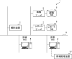
- FIG. 1 is a diagram showing a schematic configuration of an information processing system 1.
- An information processing system 1 shown in FIG. 1 performs imaging of a subject's site to be examined based on an examination order from a doctor of a clinical department using a known ordering system, and stores medical images acquired by the imaging.
- an interpretation doctor performs interpretation of medical images and prepares an interpretation report, and the doctor of the department that requested the interpretation views the interpretation report.
- an information processing system 1 includes an imaging device 2, an image interpretation terminal (WorkStation) 3, a medical examination WS 4, an image server 5, an image DB (DataBase) 6, a report server 7, and a report DB 8. .
- the imaging device 2, interpretation WS 3, diagnosis WS 4, image server 5, image DB 6, report server 7, and report DB 8 are connected to each other via a wired or wireless network 9 so as to be able to communicate with each other.
- Each device is a computer installed with an application program for functioning as a component of the information processing system 1 .
- the application program may be recorded on a recording medium such as a DVD (Digital Versatile Disc) and a CD-ROM (Compact Disc Read Only Memory) for distribution, and may be installed in the computer from the recording medium.
- a recording medium such as a DVD (Digital Versatile Disc) and a CD-ROM (Compact Disc Read Only Memory) for distribution, and may be installed in the computer from the recording medium.
- a recording medium such as a DVD (Digital Versatile Disc) and a CD-ROM (Compact Disc Read Only Memory) for distribution, and may be installed in the computer from the recording medium.
- the imaging device 2 is a device (modality) that generates a medical image representing the diagnosis target region by imaging the diagnosis target region of the subject. Specifically, it is a simple X-ray imaging device, a CT device, an MRI device, a PET (Positron Emission Tomography) device, and the like. A medical image generated by the imaging device 2 is transmitted to the image server 5 and stored in the image DB 6 .
- the interpretation WS3 is a computer used by a medical professional such as an interpreting doctor in a radiology department to interpret medical images and create an interpretation report, and includes the information processing apparatus 10 according to this exemplary embodiment.
- the image interpretation WS 3 requests the image server 5 to view medical images, performs various image processing on the medical images received from the image server 5 , displays the medical images, and accepts input of sentences related to the medical images. Further, the interpretation WS 3 performs analysis processing for medical images, supports creation of interpretation reports based on the analysis results, requests registration and viewing of interpretation reports to the report server 7 , and displays interpretation reports received from the report server 7 . will be These processes are performed by the interpretation WS3 executing a software program for each process.
- the clinical WS 4 is a computer used by medical staff such as doctors in clinical departments for detailed observation of medical images, viewing of interpretation reports, and creation of electronic charts. and an input device such as a keyboard and mouse.
- medical care WS 4 a medical image viewing request to the image server 5, a medical image display received from the image server 5, an interpretation report viewing request to the report server 7, and an interpretation report received from the report server 7 are displayed. .
- These processes are performed by the clinical WS 4 executing a software program for each process.
- the image server 5 is a general-purpose computer installed with a software program that provides the functions of a database management system (DBMS).
- DBMS database management system
- the image server 5 is connected with the image DB 6 .
- the form of connection between the image server 5 and the image DB 6 is not particularly limited, and may be a form of connection via a data bus, or a form of connection via a network such as NAS (Network Attached Storage) or SAN (Storage Area Network). It may be in the form of
- the image DB 6 is realized by storage media such as HDD (Hard Disk Drive), SSD (Solid State Drive) and flash memory.
- HDD Hard Disk Drive
- SSD Solid State Drive
- flash memory In the image DB 6, the medical images acquired by the imaging device 2 and the incidental information attached to the medical images are registered in association with each other.
- the incidental information includes, for example, an image ID (identification) for identifying a medical image, a tomographic ID assigned to each tomographic image included in the medical image, a subject ID for identifying a subject, and a test identifying Identification information such as an examination ID for the purpose may be included.
- the incidental information may include, for example, information on imaging such as an imaging method, imaging conditions, and imaging date and time relating to imaging of medical images.
- the "imaging method” and “imaging conditions” are, for example, the type of imaging device 2, the imaging site, the imaging protocol, the imaging sequence, the imaging technique, the use or non-use of a contrast medium, and the like.
- the incidental information may include information about the subject such as the subject's name, age, and sex.
- the image server 5 when the image server 5 receives a registration request for a medical image from the imaging device 2 , the medical image is arranged in a database format and registered in the image DB 6 . In addition, upon receiving a viewing request from the interpretation WS3 and the medical care WS4, the image server 5 searches for medical images registered in the image DB 6, and transmits the retrieved medical images to the interpretation WS3 and the medical care WS4 that requested the viewing. do.
- the report server 7 is a general-purpose computer installed with a software program that provides the functions of a database management system.
- the report server 7 is connected with the report DB 8 .
- the form of connection between the report server 7 and the report DB 8 is not particularly limited, and may be a form of connection via a data bus or a form of connection via a network such as NAS or SAN.
- the report DB 8 is realized, for example, by storage media such as HDD, SSD and flash memory. An interpretation report created in the interpretation WS3 is registered in the report DB8.
- the report server 7 when the report server 7 receives an interpretation report registration request from the interpretation WS 3 , it formats the interpretation report into a database format and registers it in the report DB 8 . In addition, when the report server 7 receives a viewing request for an interpretation report from the interpretation WS3 and the medical treatment WS4, it searches for the interpretation report registered in the report DB8, and sends the retrieved interpretation report to the interpretation WS3 and the medical treatment Send to WS4.
- the network 9 is, for example, a LAN (Local Area Network) or a WAN (Wide Area Network).
- the imaging device 2, image interpretation WS 3, medical care WS 4, image server 5, image DB 6, report server 7, and report DB 8 included in the information processing system 1 may be located in the same medical institution, or may be located in different medical institutions. It may be placed in an institution or the like. Further, the number of each of the imaging device 2, interpretation WS 3, diagnosis WS 4, image server 5, image DB 6, report server 7 and report DB 8 is not limited to the number shown in FIG. It may consist of a single device.
- the information processing device 10 has a function of supporting the creation of medical documents such as interpretation reports based on medical images captured by the imaging device 2 .
- the information processing apparatus 10 is included in the interpretation WS3.
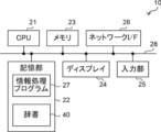
- the information processing apparatus 10 includes a CPU (Central Processing Unit) 21, a non-volatile storage section 22, and a memory 23 as a temporary storage area.
- the information processing apparatus 10 also includes a display 24 such as a liquid crystal display, an input unit 25 such as a keyboard and a mouse, and a network I/F (Interface) 26 .
- a network I/F 26 is connected to the network 9 and performs wired or wireless communication.
- the CPU 21, the storage unit 22, the memory 23, the display 24, the input unit 25, and the network I/F 26 are connected via a bus 28 such as a system bus and a control bus so that various information can be exchanged with each other.
- the storage unit 22 is realized by storage media such as HDD, SSD, and flash memory, for example.
- the storage unit 22 stores an information processing program 27 in the information processing apparatus 10 and a dictionary 40 (details of which will be described later).
- the CPU 21 reads out the information processing program 27 from the storage unit 22 , expands it in the memory 23 , and executes the expanded information processing program 27 .
- CPU 21 is an example of a processor of the present disclosure.
- the information processing device 10 for example, a personal computer, a server computer, a smart phone, a tablet terminal, a wearable terminal, or the like can be appropriately applied.
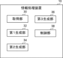
- the information processing apparatus 10 includes an acquisition unit 30, a first generation unit 32, a second generation unit 34, a third generation unit 36, and a control unit 38.
- FIG. 3 By executing the information processing program 27 by the CPU 21 , the CPU 21 functions as an acquisition unit 30 , a first generation unit 32 , a second generation unit 34 , a third generation unit 36 and a control unit 38 .
- the acquisition unit 30 acquires from the image server 5 a medical image for which an interpretation report is to be created.
- the medical image acquired by the acquiring unit 30 is a medical image relating to the lungs.
- the first generation unit 32 generates element information used for medical diagnosis based on the medical image acquired by the acquisition unit 30 . Specifically, the first generating unit 32 generates at least an area of structures (eg, organs and tissues) included in the medical image and an area of abnormal shadows (eg, shadows due to lesions such as nodules) included in the medical image. Extract a region of interest containing one. For extraction of the region of interest, for example, a trained model such as a CNN (Convolutional Neural Network), which is pre-learned such that a medical image is input and a region of interest extracted from the medical image is output, may be used. Further, the first generation unit 32 may extract a region in the medical image specified by the user via the input unit 25 as the region of interest.
- a trained model such as a CNN (Convolutional Neural Network)
- the first generation unit 32 generates element information related to the region of interest extracted from the medical image.
- a trained model such as CNN, which is pre-learned such that the region of interest in the medical image is input and the element information regarding the region of interest is output, may be used. good.
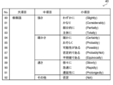
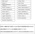
- FIGS. 4-8 show an example of a dictionary 40 in which element information that can be generated by the first generation unit 32 is predetermined.
- the dictionary 40 shown in FIGS. 4-8 is primarily concerned with lungs.
- 4 and 5 show element information indicating the name (type), properties, measured values, position, and presumed disease name (including negative or positive evaluation results) of the region of interest included in the medical image.
- the first generation unit 32 may specify at least one of the name (type), properties, measurement values, position, estimated disease name, and the like for the region of interest extracted from the medical image, and generate it as element information.
- FIG. 6 shows element information that indicates the physical interrelationship between multiple different regions of interest included in a medical image.
- the first generation unit 32 may identify their physical interrelationships and generate element information.
- FIG. 6 shows element information indicating the temporal change of the region of interest included in the medical image.
- the first generating unit 32 identifies temporal changes in regions of interest included in each medical image. and may be generated as element information.
- FIG. 7 shows elemental information indicating the imaging method, imaging conditions, imaging time phase, and imaging date and time related to imaging of medical images.
- each medical image is attached with incidental information including information on imaging when it is registered in the image DB 6 .
- the first generator 32 may generate the element information based on additional information attached to the medical image.
- FIG. 8 shows the element information that modifies the above element information.
- the first generator 32 may add the element information shown in FIG. 8 to the element information shown in FIGS.
- the first generating unit 32 for example, from an external device such as the medical care WS 4, information included in the examination order and electronic medical record, information indicating various examination results such as blood test and infectious disease test, and health Information or the like indicating the result of diagnosis may be acquired and generated as appropriate element information.
- the first generation unit 32 may generate element information based on information input via the input unit 25 .
- the first generation unit 32 may match a keyword input by the user via the input unit 25 with the dictionary 40 and select element information corresponding to the keyword.
- the first generation unit 32 may present the dictionary 40 on the display 24 and accept the designation of the element information by the user.
- FIG. 9 and 10 describe element information generated by the first generation unit 32 and sentences to be generated based on the element information.
- the element information is described in English as shown in the dictionary 40 of FIGS. 4-8. Properties and locations are noted after the name of the corresponding region of interest. Measurement values and negative (minus) or positive (plus) evaluation results are shown in [ ].
- the second generation unit 34 organizes the element information generated by the first generation unit 32, thereby making preparations for facilitating the generation of appropriate sentences.
- the second generating unit 34 is represented by a node indicating each of a plurality of pieces of elemental information related to the medical image generated by the first generating unit 32, and an edge connecting nodes of related elemental information. generates a graph structure with
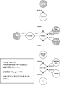
- FIG. 11 to 13 show graph structures generated by the second generation unit 34 and sentences to be generated based on the graph structures.
- the element information is described in English as shown in the dictionary 40 of FIGS. 4 to 8.
- FIG. 11 to 13 are so-called directed graphs in which nodes are represented by circles and edges are represented by arrows, and nodes of related element information are connected by edges. Also, the meaning of edge is represented in italics. In the following description, the nodes and edges shown in each figure are enclosed in square brackets [ ].
- the second generation unit 34 may connect nodes representing a plurality of pieces of element information related to the same region of interest included in the medical image with edges. For example, when a "solid nodule" is included in a medical image, the region in the medical image that serves as the basis for generating the element information of "nodule” and the element information of "solid” are The region in the medical image that serves as the basis for generation is the same. Therefore, as shown in FIG. 11, the second generation unit 34 connects the [Nodule] node and the [Solid] node with an edge.
- the second generation unit 34 connects nodes indicating element information about each of a plurality of different regions of interest included in the medical image to physical interrelationships of the plurality of different regions of interest (FIG. 6). ) may be joined by edges.
- S1 denotes lung segment
- a region of interest containing "Right Lung S1" as a structure and a region of interest containing "Nodule” therein as an abnormal shadow are extracted from the medical image. . Therefore, as shown in FIG. 11, the second generation unit 34 connects the [Right Lung S1] node and the [Nodule] node with an edge via the [Contain] node that indicates a physical mutual relationship.
- the second generation unit 34 generates nodes indicating element information about each region of interest included in each of a plurality of medical images of the same subject taken at different imaging times. may be terminated with edges through nodes that indicate changes in the region of interest over time (see FIG. 6). Nodes representing changes over time are connected to other nodes by edges denoting past and/or current.
- the second generation unit 34 For example, imaging is performed again on a subject that has been imaged in the past, and as a result of generating elemental information based on each of the past and current medical images, the major axis of the same nodule is increasing (Progress).
- the second generation unit 34 generates the [Nodule] node on the [past] side and the [Nodule] node on the [current] side via the [Progress] node that indicates changes over time. Connect a node with an edge.
- the second generation unit 34 may generate a graph structure as shown in FIG.
- FIG. 13 is a graph structure when it is found that the major diameter (MaxDiameter) of the same nodule is decreasing (Regress) as a result of generating elemental information based on each of past and current medical images.
- the second generation unit 34 may connect the [MaxDiameter] on the [past] side and the [current] side with an edge via a [Regress] node that indicates changes over time.
- the third generator 36 generates sentences regarding medical diagnosis based on the graph structure generated by the second generator 34 .
- the third generation unit 36 generates a learned model M (not shown) such as a CNN that has been trained in advance so that the input is a graph structure and the output is a sentence.
- a sentence may be generated by inputting a graph structure.
- a trained model M is an example of a trained model of the present disclosure.
- the dictionary 40 records a lot of element information.
- element information of the same category such as “substantial type” and “partially substantial type,” which are element information related to absorption values, are often used in the same way in sentences.
- measured values such as "major axis” are often used in the same way in sentences even if the numerical values are different.
- the lung segment of "right lung S1" illustrated in FIG. 11 is often used in the same manner in sentences even in other lung segments.
- the model M includes a substitution graph structure in which nodes in the graph structure are substituted with placeholders predetermined for each category of element information indicated by the nodes, and sentences expressed including the placeholders. , as learning data.
- FIG. 14 shows a replacement graph structure in which some nodes of the graph structure shown in FIG. 11 are replaced with placeholders, and sentences expressed including the placeholders.
- the background color of the node replaced with the placeholder is changed to gray, and the frame line is changed to a dashed line.
- the [Right Lung S1] node indicated by the specific lung segment in FIG. 11 is replaced with the [LungField] node, and [MaxDiameter 10 mm] indicated by the specific major diameter is replaced by [MaxDiameter] replaced by node.
- the [Solid] node is replaced with the upper item [Opacity] node, and the [Spiculated] node is replaced with the upper item [Margin] node (see FIG. 5).
- Corresponding character strings for sentences are also replaced with placeholders.
- the third generation unit 36 uses the learned model M to generate sentences from the graph structure (operation phase).
- the third generating unit 36 generates a permuted graph structure in which nodes in the graph structure generated by the second generating unit 34 are replaced with placeholders, and inputs the permuted graph structure to the learned model M.
- This may generate sentences expressed including placeholders.
- the third generation unit 36 converts the graph structure shown in FIG. 11 into the permutation graph structure shown in FIG. By inputting to the model M, a sentence expressed including placeholders is generated.
- the third generation unit 36 replaces the placeholders included in the text expressed including the placeholders with the character strings indicated by the element information to generate the final text.
- the sentence shown in FIG. 11 is generated as the final sentence by embedding the information indicated by the node before replacement into the placeholder portion of the sentence expressed including the placeholder shown in FIG. According to such a form, the accuracy of the generated sentence can be improved.
- FIG. 15 shows an example of a more complicated graph structure.
- FIG. 15 is a graph structure corresponding to the text of FIG. If the graph structure is complicated, the third generator 36 preferably divides the multiple nodes and multiple edges included in the graph structure into multiple groups and generates a sentence for each group. Specifically, the third generation unit 36 may generate sentences for each group by inputting the divided groups to the model M that has been trained.
- FIG. 16 shows an example of dividing the graph structure of FIG. 15 into three groups: Group A (indicated by dashed line), Group B (indicated by dotted line), and Group C (indicated by dashed line). Also, FIG. 17 shows an example of sentences generated for each group A to C in FIG.
- a learned model such as a CNN, which is pre-learned so that a graph structure is input and a plurality of groups divided from the graph structure are output, may be used. good.
- This trained model is, for example, a model trained using a combination of a complex graph structure as shown in FIG. 15 and a plurality of sentences corresponding to the complex graph structure as shown in FIG. 17 as learning data. .
- a trained model is a model that has learned how to divide a complex graph structure into groups from corresponding multiple sentences.
- the third generation unit 36 After generating the sentences for each group, the third generation unit 36 combines the multiple sentences generated for each group to generate sentences related to medical diagnosis. In this way, even if the graph structure is complicated, by dividing the graph into groups and generating sentences, each sentence becomes simple, so that the accuracy of the generated sentence can be improved.
- FIG. 18 shows an example of a screen D displayed on the display 24 by the controller 38.
- the screen D includes an area 92 in which the medical image acquired by the acquisition unit 30 is displayed, an area 94 in which the element information generated by the first generation unit 32 is displayed, and a third generation unit and a region 96 in which text relating to the medical diagnosis generated by 36 is displayed.
- the element information and sentences shown in FIG. 18 correspond to the graph structures and sentences shown in FIGS.
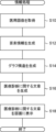
- FIG. 10 the information processing shown in FIG. 10 is executed by the CPU 21 executing the information processing program 27.
- FIG. Information processing is executed, for example, when a user gives an instruction to start execution via the input unit 25 .
- step S ⁇ b>10 the acquisition unit 30 acquires medical images from the image server 5 .
- the first generator 32 generates element information based on the medical image acquired in step S10.
- the second generation unit 34 generates a graph structure represented by nodes indicating each of the plurality of element information related to the medical image generated in step S12 and edges connecting nodes of related element information.
- the third generation unit 36 generates sentences regarding medical diagnosis based on the graph structure generated in step S14.
- the control unit 38 causes the display 24 to display the screen D including the text regarding the medical diagnosis generated in step S16, and ends this information processing.
- the information processing apparatus 10 includes at least one processor, and the processor includes nodes indicating each of a plurality of element information used for medical diagnosis, and associated element information
- the processor includes nodes indicating each of a plurality of element information used for medical diagnosis, and associated element information
- a graph structure represented by edges connecting the nodes of is generated, and sentences related to medical diagnosis are generated based on the graph structure. That is, according to the information processing apparatus 10 according to the present exemplary embodiment, by representing the element information as a graph structure, it is possible to create sentences containing a large amount and a plurality of element information, and to support the creation of medical documents.
- the acquisition unit 30 when element information is generated in advance by an external device having a function similar to that of the first generation unit 32 that generates element information based on medical images, and an interpretation report is created, the acquisition unit 30 generates A form of acquiring the element information from the device may be adopted.
- the second generation unit 34 has described the form in which the physical interrelationships of a plurality of different regions of interest (see FIG. 6) are represented as nodes, but the present invention is not limited to this.
- the second generating unit 34 may connect nodes indicating element information about each of a plurality of different regions of interest included in the medical image with edges indicating physical interrelationships between the plurality of different regions of interest.
- FIGS. 20 and 21 show graph structures in which physical interrelationships ([Contain], [Indent], [Contact]) are represented by edges. 20 corresponds to FIG. 11, and FIG. 21 corresponds to FIG. In Figures 20 and 21, edges that indicate physical interrelationships are boxed.
- the modifier [Not] is also enclosed in a square as an edge.
- the second generation unit 34 has described a form in which the temporal change of the region of interest (see FIG. 6) is represented as a node, but the present invention is not limited to this.
- the second generating unit 34 divides the nodes indicating the element information about each of the regions of interest included in each of a plurality of medical images of the same subject taken at different imaging times into each other to indicate changes in the regions of interest over time. Edges may be tied.
- FIGS. 22 and 23 show graph structures in which changes over time ([Progress], [Regress]) are represented by edges. 22 corresponds to FIG. 12, and FIG. 23 corresponds to FIG. In FIG. 22 and FIG. 23, the edges showing changes over time are enclosed by rectangles.
- the graph structure represented by nodes and edges was explained using diagrams, but the method of expressing the graph structure is not limited to diagrams.
- the graph structure represented by nodes and edges can also be represented by techniques such as RDF (Resource Description Framework) and adjacency matrix. That is, the technology of the present disclosure is applicable not only to diagrams but also to graph structures represented by RDF, adjacency matrices, and the like.
- a processing unit that executes various processes such as the acquisition unit 30, the first generation unit 32, the second generation unit 34, the third generation unit 36, and the control unit 38
- various processors shown below can be used.
- the various processors include, in addition to the CPU, which is a general-purpose processor that executes software (programs) and functions as various processing units, circuits such as FPGAs (Field Programmable Gate Arrays), etc.
- Programmable Logic Device PLD which is a processor whose configuration can be changed, ASIC (Application Specific Integrated Circuit) etc. Circuits, etc. are included.
- One processing unit may be composed of one of these various processors, or a combination of two or more processors of the same type or different types (for example, a combination of multiple FPGAs, a combination of a CPU and an FPGA). combination). Also, a plurality of processing units may be configured by one processor.
- a single processor is configured by combining one or more CPUs and software.
- a processor functions as multiple processing units.
- SoC System on Chip
- the various processing units are configured using one or more of the above various processors as a hardware structure.
- the information processing program 27 is pre-stored (installed) in the storage unit 22, but the present invention is not limited to this.
- the information processing program 27 may be provided in a form recorded on a recording medium such as a CD-ROM (Compact Disc Read Only Memory), a DVD-ROM (Digital Versatile Disc Read Only Memory), and a USB (Universal Serial Bus) memory. good.
- the information processing program 27 may be downloaded from an external device via a network.
- the technology of the present disclosure extends to a storage medium that non-temporarily stores an information processing program in addition to the information processing program.
- the technology of the present disclosure can also appropriately combine the exemplary embodiments described above.
- the description and illustration shown above are detailed descriptions of the parts related to the technology of the present disclosure, and are merely examples of the technology of the present disclosure.
- the above descriptions of configurations, functions, actions, and effects are descriptions of examples of configurations, functions, actions, and effects of portions related to the technology of the present disclosure. Therefore, unnecessary parts may be deleted, new elements added, or replaced with respect to the above-described description and illustration without departing from the gist of the technology of the present disclosure. Needless to say.
Landscapes
- Engineering & Computer Science (AREA)
- Health & Medical Sciences (AREA)
- Theoretical Computer Science (AREA)
- General Health & Medical Sciences (AREA)
- Medical Informatics (AREA)
- Physics & Mathematics (AREA)
- General Physics & Mathematics (AREA)
- Public Health (AREA)
- Primary Health Care (AREA)
- Epidemiology (AREA)
- Biomedical Technology (AREA)
- Artificial Intelligence (AREA)
- Nuclear Medicine, Radiotherapy & Molecular Imaging (AREA)
- Radiology & Medical Imaging (AREA)
- General Engineering & Computer Science (AREA)
- Databases & Information Systems (AREA)
- Computational Linguistics (AREA)
- Multimedia (AREA)
- Computer Vision & Pattern Recognition (AREA)
- Audiology, Speech & Language Pathology (AREA)
- Data Mining & Analysis (AREA)
- Pathology (AREA)
- Quality & Reliability (AREA)
- Evolutionary Computation (AREA)
- Software Systems (AREA)
- Computing Systems (AREA)
- Medical Treatment And Welfare Office Work (AREA)
Priority Applications (2)
| Application Number | Priority Date | Filing Date | Title |
|---|---|---|---|
| JP2023551881A JPWO2023054645A1 (https=) | 2021-09-30 | 2022-09-29 | |
| US18/617,626 US20240266056A1 (en) | 2021-09-30 | 2024-03-26 | Information processing apparatus, information processing method, and information processing program |
Applications Claiming Priority (2)
| Application Number | Priority Date | Filing Date | Title |
|---|---|---|---|
| JP2021-162033 | 2021-09-30 | ||
| JP2021162033 | 2021-09-30 |
Related Child Applications (1)
| Application Number | Title | Priority Date | Filing Date |
|---|---|---|---|
| US18/617,626 Continuation US20240266056A1 (en) | 2021-09-30 | 2024-03-26 | Information processing apparatus, information processing method, and information processing program |
Publications (1)
| Publication Number | Publication Date |
|---|---|
| WO2023054645A1 true WO2023054645A1 (ja) | 2023-04-06 |
Family
ID=85782929
Family Applications (1)
| Application Number | Title | Priority Date | Filing Date |
|---|---|---|---|
| PCT/JP2022/036597 Ceased WO2023054645A1 (ja) | 2021-09-30 | 2022-09-29 | 情報処理装置、情報処理方法及び情報処理プログラム |
Country Status (3)
| Country | Link |
|---|---|
| US (1) | US20240266056A1 (https=) |
| JP (1) | JPWO2023054645A1 (https=) |
| WO (1) | WO2023054645A1 (https=) |
Families Citing this family (2)
| Publication number | Priority date | Publication date | Assignee | Title |
|---|---|---|---|---|
| JP7706987B2 (ja) * | 2021-08-17 | 2025-07-14 | 富士フイルム株式会社 | 学習装置、方法およびプログラム、並びに情報処理装置、方法およびプログラム |
| JP7718915B2 (ja) * | 2021-08-30 | 2025-08-05 | 富士フイルム株式会社 | 学習装置、方法およびプログラム、並びに情報処理装置、方法およびプログラム |
Citations (1)
| Publication number | Priority date | Publication date | Assignee | Title |
|---|---|---|---|---|
| JP2018060537A (ja) * | 2016-10-06 | 2018-04-12 | 富士通株式会社 | 潜在的な診断を所与として患者により利用される医療資源を特定するためのコンピュータ装置及び方法 |
Family Cites Families (1)
| Publication number | Priority date | Publication date | Assignee | Title |
|---|---|---|---|---|
| JP6797088B2 (ja) * | 2017-08-17 | 2020-12-09 | 富士フイルム株式会社 | 学習データ生成支援装置および学習データ生成支援装置の作動方法並びに学習データ生成支援プログラム |
-
2022
- 2022-09-29 WO PCT/JP2022/036597 patent/WO2023054645A1/ja not_active Ceased
- 2022-09-29 JP JP2023551881A patent/JPWO2023054645A1/ja active Pending
-
2024
- 2024-03-26 US US18/617,626 patent/US20240266056A1/en active Pending
Patent Citations (1)
| Publication number | Priority date | Publication date | Assignee | Title |
|---|---|---|---|---|
| JP2018060537A (ja) * | 2016-10-06 | 2018-04-12 | 富士通株式会社 | 潜在的な診断を所与として患者により利用される医療資源を特定するためのコンピュータ装置及び方法 |
Non-Patent Citations (1)
| Title |
|---|
| CHRISTY Y. LI; XIAODAN LIANG; ZHITING HU; ERIC P. XING: "Knowledge-driven Encode, Retrieve, Paraphrase for Medical Image Report Generation", ARXIV.ORG, 25 March 2019 (2019-03-25), XP081157438 * |
Also Published As
| Publication number | Publication date |
|---|---|
| JPWO2023054645A1 (https=) | 2023-04-06 |
| US20240266056A1 (en) | 2024-08-08 |
Similar Documents
| Publication | Publication Date | Title |
|---|---|---|
| JP7618003B2 (ja) | 文書作成支援装置、方法およびプログラム | |
| WO2022215530A1 (ja) | 医用画像装置、医用画像方法、及び医用画像プログラム | |
| JP7000206B2 (ja) | 医用画像処理装置、医用画像処理方法、及び医用画像処理プログラム | |
| US12406755B2 (en) | Document creation support apparatus, method, and program | |
| US11978274B2 (en) | Document creation support apparatus, document creation support method, and document creation support program | |
| JP7504987B2 (ja) | 情報処理装置、情報処理方法及び情報処理プログラム | |
| US20240266056A1 (en) | Information processing apparatus, information processing method, and information processing program | |
| WO2020209382A1 (ja) | 医療文書作成装置、方法およびプログラム | |
| JPWO2019176407A1 (ja) | 学習支援装置、学習支援方法、学習支援プログラム、関心領域判別装置、関心領域判別方法、関心領域判別プログラム及び学習済みモデル | |
| JP2024009342A (ja) | 文書作成支援装置、方法およびプログラム | |
| JP7007469B2 (ja) | 医療文書作成支援装置、方法およびプログラム、学習済みモデル、並びに学習装置、方法およびプログラム | |
| JP7371220B2 (ja) | 情報処理装置、情報処理方法及び情報処理プログラム | |
| Brown et al. | Database design and implementation for quantitative image analysis research | |
| US12387825B2 (en) | Information processing apparatus, information processing method, and information processing program | |
| WO2022230641A1 (ja) | 文書作成支援装置、文書作成支援方法、及び文書作成支援プログラム | |
| WO2022196105A1 (ja) | 情報管理装置、方法およびプログラム、並びに情報処理装置、方法およびプログラム | |
| WO2023199957A1 (ja) | 情報処理装置、情報処理方法及び情報処理プログラム | |
| JP2023067186A (ja) | 情報処理装置、情報処理方法及び情報処理プログラム | |
| JP7368592B2 (ja) | 文書作成支援装置、方法およびプログラム | |
| WO2023054646A1 (ja) | 情報処理装置、情報処理方法及び情報処理プログラム | |
| JP7376715B2 (ja) | 経過予測装置、経過予測装置の作動方法および経過予測プログラム | |
| JP7483018B2 (ja) | 画像処理装置、画像処理方法及びプログラム、画像処理システム | |
| US20240266026A1 (en) | Information processing apparatus, operation method of information processing apparatus, and program | |
| JP2025117381A (ja) | 情報処理装置、情報処理方法、及び情報処理プログラム | |
| WO2023199956A1 (ja) | 情報処理装置、情報処理方法及び情報処理プログラム |
Legal Events
| Date | Code | Title | Description |
|---|---|---|---|
| 121 | Ep: the epo has been informed by wipo that ep was designated in this application |
Ref document number: 22876508 Country of ref document: EP Kind code of ref document: A1 |
|
| WWE | Wipo information: entry into national phase |
Ref document number: 2023551881 Country of ref document: JP |
|
| NENP | Non-entry into the national phase |
Ref country code: DE |
|
| 122 | Ep: pct application non-entry in european phase |
Ref document number: 22876508 Country of ref document: EP Kind code of ref document: A1 |