WO2023054169A1 - Connector and connector assembly - Google Patents
Connector and connector assembly Download PDFInfo
- Publication number
- WO2023054169A1 WO2023054169A1 PCT/JP2022/035388 JP2022035388W WO2023054169A1 WO 2023054169 A1 WO2023054169 A1 WO 2023054169A1 JP 2022035388 W JP2022035388 W JP 2022035388W WO 2023054169 A1 WO2023054169 A1 WO 2023054169A1
- Authority
- WO
- WIPO (PCT)
- Prior art keywords
- lever
- connector
- mating
- arm
- housing
- Prior art date
Links
- 238000013459 approach Methods 0.000 claims abstract description 8
- 230000013011 mating Effects 0.000 claims description 151
- 230000001105 regulatory effect Effects 0.000 description 7
- 239000000463 material Substances 0.000 description 5
- 239000011347 resin Substances 0.000 description 5
- 229920005989 resin Polymers 0.000 description 5
- 238000005452 bending Methods 0.000 description 3
- 230000000712 assembly Effects 0.000 description 2
- 238000000429 assembly Methods 0.000 description 2
- 230000000694 effects Effects 0.000 description 2
- 238000012986 modification Methods 0.000 description 2
- 230000004048 modification Effects 0.000 description 2
- 238000001125 extrusion Methods 0.000 description 1
- 230000009191 jumping Effects 0.000 description 1
Images


Classifications
-
- H—ELECTRICITY
- H01—ELECTRIC ELEMENTS
- H01R—ELECTRICALLY-CONDUCTIVE CONNECTIONS; STRUCTURAL ASSOCIATIONS OF A PLURALITY OF MUTUALLY-INSULATED ELECTRICAL CONNECTING ELEMENTS; COUPLING DEVICES; CURRENT COLLECTORS
- H01R13/00—Details of coupling devices of the kinds covered by groups H01R12/70 or H01R24/00 - H01R33/00
- H01R13/62—Means for facilitating engagement or disengagement of coupling parts or for holding them in engagement
- H01R13/639—Additional means for holding or locking coupling parts together, after engagement, e.g. separate keylock, retainer strap
-
- H—ELECTRICITY
- H01—ELECTRIC ELEMENTS
- H01R—ELECTRICALLY-CONDUCTIVE CONNECTIONS; STRUCTURAL ASSOCIATIONS OF A PLURALITY OF MUTUALLY-INSULATED ELECTRICAL CONNECTING ELEMENTS; COUPLING DEVICES; CURRENT COLLECTORS
- H01R13/00—Details of coupling devices of the kinds covered by groups H01R12/70 or H01R24/00 - H01R33/00
- H01R13/62—Means for facilitating engagement or disengagement of coupling parts or for holding them in engagement
- H01R13/629—Additional means for facilitating engagement or disengagement of coupling parts, e.g. aligning or guiding means, levers, gas pressure electrical locking indicators, manufacturing tolerances
- H01R13/62933—Comprising exclusively pivoting lever
- H01R13/62938—Pivoting lever comprising own camming means
-
- H—ELECTRICITY
- H01—ELECTRIC ELEMENTS
- H01R—ELECTRICALLY-CONDUCTIVE CONNECTIONS; STRUCTURAL ASSOCIATIONS OF A PLURALITY OF MUTUALLY-INSULATED ELECTRICAL CONNECTING ELEMENTS; COUPLING DEVICES; CURRENT COLLECTORS
- H01R13/00—Details of coupling devices of the kinds covered by groups H01R12/70 or H01R24/00 - H01R33/00
- H01R13/62—Means for facilitating engagement or disengagement of coupling parts or for holding them in engagement
- H01R13/629—Additional means for facilitating engagement or disengagement of coupling parts, e.g. aligning or guiding means, levers, gas pressure electrical locking indicators, manufacturing tolerances
- H01R13/62977—Pivoting levers actuating linearly camming means
-
- H—ELECTRICITY
- H01—ELECTRIC ELEMENTS
- H01R—ELECTRICALLY-CONDUCTIVE CONNECTIONS; STRUCTURAL ASSOCIATIONS OF A PLURALITY OF MUTUALLY-INSULATED ELECTRICAL CONNECTING ELEMENTS; COUPLING DEVICES; CURRENT COLLECTORS
- H01R2201/00—Connectors or connections adapted for particular applications
- H01R2201/26—Connectors or connections adapted for particular applications for vehicles
Definitions
- the present disclosure relates to connectors and connector assemblies.
- the connector assembly includes a mating connector and a connector connectable by relatively moving in a first direction along a first axis with respect to the mating connector.
- the mating connector includes mating terminals and a mating housing.
- the connector includes terminals that can be electrically connected to mating terminals, and a connector housing that can be fitted to the mating housing.
- a connector for example, there is a connector having an arm that is rotatable with respect to the connector housing and that assists the fitting operation with the mating housing by the arm (see, for example, Patent Document 1). .
- This connector has a pair of arms.
- the pair of arms has locking portions that are engaged with each other by the elasticity of the arms themselves before the connector housing is mated with the mating housing.
- the pair of arms are provisionally locked at the initial position by mutual engagement of the locking portions.
- the arm is temporarily locked by the locking portion at the initial position, the locking portion that is engaged by the elasticity of the arm itself has a weak engaging force. There is a possibility that the temporary locking may be easily released by the external force. If the arm moves from the initial position before the connector housing is mated with the mating housing, for example, the connector housing cannot be mated with the mating housing. .
- the present disclosure has been made to solve the above problems, and an object thereof is to provide a connector and a connector assembly in which a connector housing can be stably and normally mated with a mating housing. .
- a connector of the present disclosure is connectable by relatively moving in a first direction along a first axis with respect to a mating connector including mating terminals and a mating housing, wherein the mating connector a terminal connectable to the terminal; a connector housing that accommodates the terminal and can be fitted with the mating housing; A lever that is movable relative to the connector housing along the first axis within a range from the second position, and a moving direction of the lever that is drivingly connected to the lever and that accompanies the relative movement of the lever. and arms that move in different directions, the connector housing having a slit extending along the first axis, and the mating housing and the mating housing as the lever moves from the first position to the second position.
- the arm has a locking projection capable of regulating the movement of the arm by being fitted into the slit when the lever is located at the first position.
- the lever has an elastic piece that presses the arm in the direction in which the locking projection fits into the slit, and the locking projection pushes out the mating housing in an initial state of mating with the connector housing. It is pushed out of the slit by the part.
- a connector assembly of the present disclosure includes the above connector and the mating connector.
- the connector housing can be stably and normally mated with the mating housing.
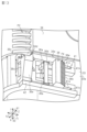
- FIG. 1 is an exploded perspective view of a connector assembly in one embodiment
- FIG. FIG. 2 is an exploded perspective view of a connector in one embodiment
- FIG. 3 is a plan view of a connector housing and arms in one embodiment.
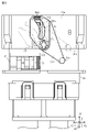
- FIG. 4 is a plan view of the connector assembly in an initial state of mating according to one embodiment.
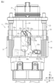
- FIG. 5 is a plan view of the mated state of the connector assembly in one embodiment.
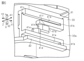
- FIG. 6 is a perspective view of a mounting portion in one embodiment.
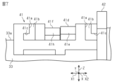
- FIG. 7 is a side view of a mounting portion in one embodiment;
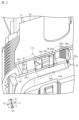
- FIG. 8 is a perspective view of a locking member in one embodiment;
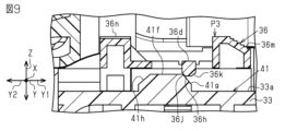
- FIG. 9 is a cross-sectional view of an attachment portion and a locking member in one embodiment.
- FIG. 10 is a cross-sectional view of an attachment portion and a locking member in one embodiment.
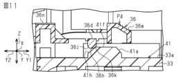
- FIG. 11 is a cross-sectional view of an attachment portion and a locking member in one embodiment.
- FIG. 12 is a partial perspective view of a connector assembly in one embodiment;
- FIG. 13 is a partial perspective view of a connector assembly in one embodiment;
- FIG. 14 is a partial cross-sectional view of a connector in one embodiment.
- FIG. 15 is a partial front view of a connector in one embodiment;
- FIG. 16 is a perspective view of an arm in one embodiment;
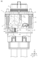
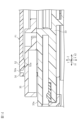
- FIG. 17 is a partial cross-sectional view of a connector assembly in one embodiment;
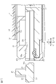
- Figure 18 is a partial cross-sectional view of a connector assembly in one embodiment.
- the connector of the present disclosure is [1] A connector that can be connected by being moved in a first direction along a first axis relative to a mating connector that includes a mating terminal and a mating housing, wherein the connector is connected to the mating terminal.
- a connector housing that accommodates the terminals and is matable with the mating housing; a first position attached to the connector housing and a second position separated from the first position in the first direction; and a lever that is movable relative to the connector housing along the first axis, and is drivingly connected to the lever and moves in a direction different from the moving direction of the lever as the lever moves relative to the connector housing.
- the connector housing having a slit extending along the first axis for mating with the mating housing as the lever moves from the first position to the second position.
- the arm has a locking projection capable of regulating movement of the arm by being fitted into the slit when the lever is located at the first position; has an elastic piece that presses the arm in the direction in which the locking projection fits into the slit, and the locking projection is pushed by the extruded portion of the mating housing in the initial state of mating with the connector housing. pushed out through the slit.
- the locking projection is fitted into the slit by the elastic piece of the lever in a state where the locking projection is not pushed out of the slit by the extruding portion of the mating housing in the initial state of mating with the connector housing. pressed in the direction
- the movement of the arm is restricted by fitting the locking projection into the slit.
- the movement of the lever drivingly connected to the arm is also restricted. Therefore, for example, the arm and lever are restrained from moving from their initial positions before the connector housing is mated with the mating housing. As a result, problems caused by the arm and lever moving from their initial positions can be avoided, and the connector housing can be stably and normally mated with the mating housing.
- the connector housing is prevented from being incorrectly assembled with a mating housing other than the mating housing having the push-out portion.
- the arm is allowed to move when the locking projection is pushed out of the slit by the push-out portion of the mating housing in the initial mating state.
- the connector housing is engaged with the mating housing.
- the arm has an engaging portion that can be engaged with the engaged portion of the mating housing, and the connector housing moves as the lever moves from the first position to the second position. It is preferable that the engaging portion, which is engaged with the engaged portion, also moves so as to move relative to the mating housing and approach a mated state with the mating housing.
- the arm moves as the lever moves from the first position to the second position, and the engaging portion engaged with the engaged portion of the mating housing also moves, thereby moving the connector housing to the mating portion. It is possible to approximate the mated state with the side housing.
- the engaging portion is engaged with the engaged portion in the initial fitting state.
- the arm in the initial state of mating the connector housing and the mating housing, the arm is allowed to move and the engaging portion is engaged with the engaged portion, so that the lever is operated.
- the connector housing and the mating housing can be brought into a properly fitted state. That is, in a configuration in which the engaging portion can be disengaged from the engaged portion while the movement of the arm is permitted in the mating initial state, the lever may be erroneously operated in the disengaged state. , this can be avoided. Therefore, the connector housing and the mating housing can be more stably and normally mated.
- the slit allows the engaged portion to move along the first axis while projecting the engaged portion toward the engaging portion.
- the slit has a function of inserting the push-out portion for inserting the locking projection capable of regulating the movement of the arm and pushing out the locking projection, and allowing the engaged portion to protrude toward the engaging portion. and a function of making the engaged portion movable along the first axis. Therefore, the configuration of the connector housing is simpler than, for example, a configuration in which two slits are provided in the connector housing and two slits are provided with two functions.
- the locking projection has a component of force in a direction resisting the pressing force of the elastic piece when the lever is about to move from the first position to the second position while being fitted in the slit. It is preferable to have a locking surface in contact with the inner wall surface of the slit so as not to generate a .
- the locking surface of the locking projection is in a direction against the pressing force of the elastic piece even if the lever is moved from the first position to the second position.
- Contact with the inner wall surface of the slit so as not to generate a force component. Therefore, movement of the arm from the initial position is strongly suppressed.
- the connector housing has a step on the surface facing the arm, and the locking projection is for getting over the step when the lever moves from the second position side to the first position side. It is preferable to have a first inclined surface that generates a force component of .
- the locking projection has a second inclined surface that contacts the pushing portion so as to generate a force component in a direction in which it is pushed out from the slit when the fitting initial state is approached.
- the second slanted surface of the locking projection in contact with the pushing portion generates a component of force in the direction in which the projection is pushed out of the slit.
- the stop protrusion is smoothly pushed out from the slit.
- the elastic piece presses the arm when the lever is at the first position, and does not press the arm when the lever is not at the first position. is preferred.
- the elastic piece has a third inclined surface that generates a force component for riding on the arm when the lever moves from the second position side to the first position. According to this configuration, when the lever moves from the second position side to the first position, the force component for riding on the arm is generated by the third inclined surface of the elastic piece, so that the elastic piece smoothly moves on the arm. It is possible to get on, and it will be in a state of smoothly pressing the arm.
- the connector assembly of the present disclosure comprises: [10] Provided with the above connector and the mating connector. According to this configuration, in the connector assembly, the connector housing can be stably and normally mated with the mating housing.
- the connector assembly 11 includes a mating connector 21 and a connector 31 that can be connected by moving relative to the mating connector 21 in a first direction X1 along a first axis X.
- the connector assembly 11 is provided in a vehicle.
- a vehicle includes in-vehicle equipment such as a high-voltage battery and an inverter, and these in-vehicle equipment are connected to each other via a wire harness WH.
- the connector assembly 11 is provided, for example, as a component for connecting the vehicle-mounted device and the wire harness WH.
- a first axis X, a second axis Y orthogonal to the first axis X, and a third axis Z orthogonal to the first axis X and the second axis Y are shown.
- a first direction X1 that is one direction along the first axis X and a first opposite direction X2 that is the other direction along the first axis X and opposite to the first direction X1 is illustrated.
- a second direction Y1 that is one direction along the second axis Y and a second opposite direction Y2 that is the other direction along the second axis Y and opposite to the second direction Y1 are shown. is illustrated.
- the mating connector 21 includes mating terminals 22 and a mating housing 23 that accommodates the mating terminals 22 .
- the mating terminal 22 extends along the first axis X. As shown in FIG. Two mating terminals 22 are provided side by side along the second axis Y. As shown in FIG. The end of the mating terminal 22 on the first direction X1 side is connected to, for example, a connection terminal of an in-vehicle device.
- the mating housing 23 is made of an insulating resin material.
- the mating housing 23 is formed in a rectangular tubular shape and opens in a first opposite direction X2 that is opposite to the first direction X1.
- a wall portion 23a extending along the second axis Y has a protruding extension portion 24 that protrudes outward along the third axis Z and extends along the first axis X.
- An engaged portion 25 projecting along the third axis Z is provided on the side of the projecting extension portion 24 in the first opposite direction X2.
- the engaged portion 25 is formed in a cylindrical shape.
- a portion of the projecting extension portion 24 that is separated from the engaged portion 25 in the first opposite direction X2 constitutes a push-out portion 26 .
- the end portion of the mating housing 23 on the first direction X1 side is fixed to, for example, a housing of an in-vehicle device.
- the connector 31 includes terminals 32 , a connector housing 33 that accommodates the terminals 32 , and a lever 34 attached to the connector housing 33 , an arm 35 and a lock member 36 .
- the terminals 32 extend along the first axis X, as shown in FIG. Two terminals 32 are provided side by side along the second axis Y, and are arranged so as to be electrically connectable to the mating terminal 22 . In the terminal 32, the end on the first opposite direction X2 side is connected to the core wire of the wire harness WH.
- the connector housing 33 is made of an insulating resin material. As shown in FIGS. 1 and 2, the connector housing 33 is formed in a square tubular shape and opens in the first direction X1. The connector housing 33 can be fitted with the mating housing 23 . Specifically, the connector housing 33 can be fitted onto the mating housing 23 by moving the connector 31 relative to the mating connector 21 in the first direction X1. As shown in FIG. 2, in the connector housing 33, a wall portion 33a extending along the second axis Y has a slit 33b passing through along the third axis Z and extending along the first axis X. As shown in FIG.
- the slit 33b extends from the end of the connector housing 33 on the first direction X1 side in the first opposite direction X2.
- the slit 33b is formed so that the projecting extension 24 including the extrusion 26 of the mating housing 23 can be introduced. Further, the slit 33 b allows the engaged portion 25 to move along the first axis X while projecting the engaged portion 25 to the outside of the connector housing 33 .
- the wall portion 33a has a rotation shaft 33c that protrudes outward along the third axis Z. As shown in FIG.
- the rotation shaft 33c is provided at the center of the connector housing 33 in the width direction along the second axis Y. As shown in FIG.
- a wall portion 33d extending along the third axis Z has a rail portion 33e that protrudes outward along the second axis Y and extends along the first axis X.
- the periphery of the slit 33b is formed as a thick portion 33f that is thicker than other portions.
- the wall portion 33a has a step 33g at the edge of the thick portion 33f.
- the wall portion 33a has a mounting portion 41 to which the lock member 36 can be mounted.
- the mounting portion 41 is mounted by moving the lock member 36 relative to the mounting portion 41 in the second direction Y1 along the second axis Y. As shown in FIG.
- the mounting portion 41 is provided on the side of the wall portion 33a away from the slit 33b and the rotating shaft 33c in the first opposite direction X2.
- the mounting portion 41 is provided on the side of the wall portion 33a away from the slit 33b and the rotating shaft 33c in the second opposite direction Y2, which is the direction opposite to the second direction Y1.
- the mounting portion 41 has a pair of rail grooves 41a recessed along the third axis Z and extending along the second axis Y. As shown in FIGS.
- the rail groove 41a opens in the second opposite direction Y2.
- the mounting portion 41 also has an end portion 41b that closes the second direction Y1 of the rail groove 41a at the end of the rail groove 41a on the second direction Y1 side.
- the rail groove 41a has a lateral groove 41c recessed in a direction crossing the recess direction of the rail groove 41a.
- the mounting portion 41 has a retaining projection 41d between the pair of rail grooves 41a. As shown in FIG.
- the retaining projection 41d has an inclined surface 41e at the corner on the second opposite direction Y2 side.
- the mounting portion 41 has a position holding convex portion 41f between the pair of rail grooves 41a. As shown in FIG. 6, the position holding convex portion 41f is arranged to be displaced from the retainer convex portion 41d in the first direction X1. In addition, the position-holding convex portion 41f is displaced from the retainer convex portion 41d toward the second direction Y1. As shown in FIGS. 9 and 11, the position holding convex portion 41f has an inclined surface 41g at a corner on the second direction Y1 side. The position holding convex portion 41f has an inclined surface 41h at the corner on the second opposite direction Y2 side.
- the wall portion 33a of the connector housing 33 has a support portion 42.
- the support portion 42 is provided on the side of the attachment portion 41 in the first opposite direction X2.
- the support portion 42 is erected along the third axis Z and extends along the second axis Y.
- the support portion 42 is provided so as to come into contact with the end surface of the lock member 36 attached to the attachment portion 41 on the first opposite direction X2 side.
- the lever 34 is made of a resin material. As shown in FIGS. 1 and 2, the lever 34 is shaped like a square tube. The inner surface of the lever 34 has a recess 34a that extends along the first axis X and into which the rail portion 33e of the connector housing 33 can be fitted. The lever 34 is fitted onto the connector housing 33 . The lever 34 can move relative to the connector housing 33 along the first axis X by guiding the recess 34a to the rail portion 33e.
- the lever 34 has a first position P1 (see FIGS. 1 and 4) on the side of the connector housing 33 in the first opposite direction X2 and a second position P2 (see FIG. 4) away from the first position P1 in the first direction X1. 5) can be moved relative to the connector housing 33 .
- the wall portion 34b extending along the second axis Y has a connected portion 34c extending along the third axis Z.
- the connected portion 34c is provided on the lever 34 near the end in the second direction Y1 along the second axis Y.
- the connected portion 34c extends along the second axis Y and is slightly inclined toward the first opposite direction X2 toward the second direction Y1.
- the lever 34 has a contact portion 34d.
- the contact portion 34d is provided at the end of the lever 34 on the first opposite direction X2 side. In other words, a part of the end surface of the lever 34 on the first opposite direction X2 side serves as the contact portion 34d.
- the arm 35 is made of a resin material. As shown in FIG. 3, the arm 35 includes a central hole 35a, a pair of engaging portions 35b extending in one direction around the central hole 35a, and a pair of engaging portions 35b extending in one direction around the central hole 35a and extending in the other direction opposite to the engaging portion 35b around the central hole 35a. and an extending extension 35c.
- the arm 35 is attached to the connector housing 33 so that the rotating shaft 33c passes through the central hole 35a. That is, the arm 35 is rotatably supported by the rotating shaft 33c.
- the pair of engaging portions 35b rotates about the center hole 35a in the second opposite direction Y2, which is the direction opposite to the second direction Y1, and the extending portion 35c rotates in the second direction Y1. provided to rotate on the side.
- the pair of engaging portions 35b constitute slits 35d by mutually facing surfaces. As shown in FIG. 4, the gap between the slits 35d is set so that the engaged portion 25 of the mating housing 23 can be inserted. Thereby, the pair of engaging portions 35 b can be engaged with the engaged portion 25 .
- the slit 35d moves the engaged portion 25 to the base end side of the engaging portion 35b and in the first opposite direction by rotating the arm 35 and moving the distal ends of the pair of engaging portions 35b in the first opposite direction X2. It is curved in a direction that allows it to be retracted to the X2 side.
- the distal end of the extended portion 35c has a connecting shaft 35e projecting along the third axis Z.
- the connecting shaft 35 e is provided so as to pass through the connected portion 34 c of the lever 34 .
- the connecting shaft 35 e is drivingly connected to the lever 34 so as to move the arm 35 in a direction different from the movement direction of the lever 34 as the lever 34 moves relative to the first axis X.
- the connecting shaft 35 e is drivingly connected to the lever 34 so as to rotate the arm 35 while moving within the connected portion 34 c as the lever 34 moves relative to the first axis X.
- the arm 35 is drivingly connected to the lever 34 .
- the connector housing 33 is closer to being fitted with the mating housing 23 as the lever 34 moves from the first position P1 (see FIG. 4) to the second position P2 (see FIG. 5). ing. Specifically, as the lever 34 moves from the first position P1 to the second position P2, the connector housing 33 also moves the engaging portion 35b engaged with the engaged portion 25 of the mating housing 23, thereby It is configured to move relative to the housing 23 and approach a fitted state. That is, as the lever 34 moves from the first position P1 to the second position P2, the connecting shaft 35e passing through the connected portion 34c of the lever 34 moves from the fifth position P5 (see FIG. 4) to the sixth position P6 (see FIG. 5). ) to rotate the arm 35 . Then, the engaging portion 35b, which moves together with the arm 35, acts to pull in the engaged portion 25, so that the connector housing 33 moves relative to the mating housing 23 and approaches the mating state with the mating housing 23. It will be.
- the lock member 36 is made of a resin material. As shown in FIGS. 8, 12, and 13, the lock member 36 includes a pair of sliding portions 36a, a first connecting portion 36b, a second connecting portion 36c, and a second connecting portion 36c that connect the pair of sliding portions 36a. 3 connection part 36d.
- the sliding portion 36a fits into the rail groove 41a of the mounting portion 41 and is slidable along the rail groove 41a.
- the sliding portion 36a has a convex portion 36e that fits into the lateral groove 41c of the rail groove 41a.
- the locking member 36 is attached to the mounting portion 41 by moving in the second direction Y1 relative to the mounting portion 41 so that the sliding portion 36a is fitted in the rail groove 41a and the convex portion 36e is fitted in the lateral groove 41c. be done.
- the lock member 36 moves along the second axis Y to the third position P3 (see FIGS. 4, 9 and 12) and the fourth position P4 (see FIG. 12) by sliding the sliding portion 36a along the rail groove 41a. 5, FIGS. 10, 11 and 13).
- the first connection portion 36b connects the ends of the pair of sliding portions 36a on the second direction Y1 side.
- the second connecting portion 36c connects the ends of the pair of sliding portions 36a on the second opposite direction Y2 side.
- the third connecting portion 36d connects intermediate portions of the sliding portions 36a.
- the third connecting portion 36d has a retaining portion 36f.
- the retainer portion 36f protrudes toward the wall portion 33a of the connector housing 33 from the third connecting portion 36d.
- the retainer portion 36f engages with the retainer convex portion 41d in the second opposite direction Y2, whereby the attachment portion 41 of the lock member 36 is removed. prevent escape from
- the retaining portion 36f has an inclined surface 36g at the corner on the second direction Y1 side.
- the inclined surface 36g of the retainer portion 36f and the inclined surface 41e of the retainer projection portion 41d are in the direction in which the third connecting portion 36d separates from the wall portion 33a of the connector housing 33 when the lock member 36 is assembled to the mounting portion 41.
- the retaining portion 36f can climb over the retaining convex portion 41d by bending the third connecting portion 36d due to the movement of the lock member 36 relative to the mounting portion 41 in the second direction Y1. Therefore, the lock member 36 can be smoothly attached to the attachment portion 41 by moving relative to the attachment portion 41 in the second direction Y1.
- the third connecting portion 36d has a position holding portion 36h.
- the position holding portion 36h protrudes toward the wall portion 33a of the connector housing 33 from the third connecting portion 36d.
- the position holding portion 36h engages with the position holding convex portion 41f in the second opposite direction Y2 while the lock member 36 is in the third position P3.
- the lock member 36 is held at the third position P3 by suppressing movement from the position P3 to the fourth position P4. Note that the lock member 36 at the third position P3 is restrained from moving in the second direction Y1 by the end portion 41b (see FIG. 6). As shown in FIG.
- the position holding portion 36h engages with the position holding convex portion 41f in the second direction Y1 while the lock member 36 is at the fourth position P4, so that the lock member 36 is held at the fourth position P4.
- the lock member 36 is held at the fourth position P4 by suppressing the movement from P4 to the third position P3.
- the lock member 36 at the fourth position P4 is restrained from moving in the second opposite direction Y2 by the retaining projection 41d (see FIG. 10).
- the position holding portion 36h has an inclined surface 36j at the corner on the second opposite direction Y2 side.
- the slanted surface 36j of the position holding portion 36h and the slanted surface 41g of the position holding convex portion 41f prevent the third connecting portion 36d from moving toward the connector housing when the lock member 36 is moved from the third position P3 to the fourth position P4.
- 33 generates a component of force that causes it to bend in a direction away from the wall portion 33a.
- the position holding portion 36h has an inclined surface 36k at a corner on the second direction Y1 side.
- the slanted surface 36k of the position holding portion 36h and the slanted surface 41h of the position holding convex portion 41f prevent the third connecting portion 36d from moving toward the connector housing when the lock member 36 is moved from the fourth position P4 to the third position P3.
- 33 generates a component of force that causes it to bend in a direction away from the wall portion 33a.
- the position holding portion 36h can climb over the position holding convex portion 41f by bending the third connecting portion 36d due to the movement of the lock member 36 relative to the mounting portion 41 along the second axis Y. .
- the lock member 36 moves the lock member 36 along the second axis Y with a force capable of bending the third connecting portion 36d, thereby changing the position of the lock member 36 to the third position P3 and the fourth position P3. It is possible to switch to the position P4.
- the first connecting portion 36b has an operation portion 36m.
- the operation portion 36m has, for example, a staircase shape so that the operator can easily operate the lock member 36 with his or her fingers.
- the second connecting portion 36c has a locking portion 36n. As shown in FIGS. 5 and 13, the lock portion 36n contacts the contact portion 34d of the lever 34 located at the second position P2 while the lock member 36 is located at the fourth position P4. By doing so, the movement of the lever 34 toward the first position P1 is restricted. Further, the lock portion 36n is locked by the contact portion 34d of the lever 34 located at the second position P2 and the support portion 42 of the connector housing 33 while the lock member 36 is located at the fourth position P4. It will be in a state of being sandwiched along the first axis X.
- the lock portion 36n of the present embodiment increases the height from the wall portion 33a toward the support portion 42 side, that is, toward the first opposite direction X2 so as to match the height from the wall portion 33a of the support portion 42. It has an inclined portion 36p that is gradually lowered.
- the lock member 36 is covered with the lever 34 when the lock member 36 is arranged at the third position P3 and the lever 34 is arranged at the first position P1. That is, as shown in FIG. 12, the lock member 36 is placed at the third position P3 and the lever 34 is placed at the first position P1, and the lock member 36 is placed between the wall portion 33a. It has a housing portion 34e that is housed therebetween.
- the lock member 36 is restricted from moving from the third position P3 to the fourth position P4 by contacting the lever 34 while the lever 34 is located at the first position P1. That is, as shown in FIG. 12, the lever 34 is moved to the fourth position P4 of the lock member 36 in a state where the lock member 36 is arranged at the third position P3 and the lever 34 is arranged at the first position P1.
- has a restricting surface 34f that restricts the movement of the 34 f of control surfaces are comprised by the inner wall surface of the accommodating part 34e.
- the locking member 36 is exposed from the lever 34 when the lever 34 is arranged at the second position P2. Specifically, when the lever 34 is located at the second position P2, the lock member 36 is exposed from the lever 34 so that the lock member 36 can be operated by the operator's finger, and cannot come into contact with the restricting surface 34f. As a result, it becomes possible to move from the third position P3 to the fourth position P4.
- arm 35 has locking projection 51 .
- the locking protrusion 51 can restrict the movement of the arm 35 at the initial position by being fitted into the slit 33b when the lever 34 is located at the first position P1.
- the lever 34 has an elastic piece 52. As shown in FIGS. As shown in FIG. 15, the elastic piece 52 presses the arm 35 in the direction in which the locking projection 51 fits into the slit 33b.
- the mating initial state is a state in which the connector housing 33 and the mating housing 23 are slightly mated as shown in FIG. It is in a state in which it enters between the tip portions and is in an engaged state with the engaging portion 35b.
- the locking projection 51 has a locking surface 51a that can come into contact with the inner wall surface 33h of the slit 33b.
- the locking surface 51a is oriented in a direction that resists the pressing force of the elastic piece 52 when the lever 34 is about to move from the first position P1 to the second position P2 with the locking projection 51 fitted in the slit 33b. It contacts with the inner wall surface 33h of the slit 33b so as not to generate a force component. That is, the inner wall surface 33h and the locking surface 51a are parallel planes along the third axis Z. As shown in FIG.
- the locking surface 51a is aligned with the third axis Z.
- the movement of the arm 35 is regulated by making surface contact with the inner wall surface 33h in the direction orthogonal to .
- the locking projection 51 has a first inclined surface 51b.
- the first inclined surface 51b is inclined with respect to the plane along the third axis Z. As shown in FIG.
- the first inclined surface 51b generates a force component for overcoming the step 33g on the surface of the connector housing 33 facing the arm 35 when the lever 34 moves from the second position P2 side to the first position P1 side.
- the locking projection 51 has a second inclined surface 51c.
- the second inclined surface 51c is inclined with respect to the plane along the third axis Z. As shown in FIG. The second inclined surface 51c contacts the push-out portion 26 so as to generate a force component in the direction of pushing out from the slit 33b when the connector housing 33 and the mating housing 23 approach the initial mating state. 17 shows a state in which the connector housing 33 and the mating housing 23 are not mated, and FIG. 18 shows a state in which the connector housing 33 and the mating housing 23 are initially mated.
- the push-out portion 26 of the present embodiment has an inclined surface 26a that contacts the locking projection 51 so as to generate a force component in the direction of pushing the locking projection 51 out of the slit 33b when the fitting initial state is approached.
- the elastic piece 52 is provided on part of the wall portion 34b of the lever 34.
- the wall portion 34b has a U-shaped slit 34g, and a portion defined by the slit 34g constitutes an elastic piece 52.
- FIG. 1 A portion defined by the slit 34g constitutes an elastic piece 52.
- the elastic piece 52 has a pressing portion 52a at its tip, and the pressing portion 52a protrudes toward the arm 35 side.
- the elastic piece 52 presses the arm 35 with the pressing portion 52a in a state where the lever 34 is arranged at the first position P1. Also, the elastic piece 52 does not press the arm 35 when the lever 34 is not located at the first position P1. For example, as shown in FIG. 5, the elastic piece 52 is out of position with the arm 35 and does not press the arm 35 when the lever 34 is located at the second position P2.
- the pressing portion 52a has a third inclined surface 52b.
- the third inclined surface 52b generates a force component for the pressing portion 52a to ride on the arm 35 when the lever 34 moves from the second position P2 side to the first position P1.
- the lever 34 of the connector 31 before being connected to the mating connector 21 is arranged at the first position P1.
- the arm 35 is pressed by the elastic piece 52 in the direction in which the locking projection 51 fits into the slit 33b. Since the locking projection 51 is fitted in the slit 33b, the rotation of the arm 35 is suppressed, and the arm 35 is maintained at the initial position. As a result, the lever 34, which is drivingly connected to the arm 35, is also restrained from moving to the second position P2.
- the operator moves the connector 31 relative to the mating connector 21 in the first direction X1 so that the connector housing 33 is connected to the mating connector 21 as shown in FIG. It is in an initial fitting state in which the side housing 23 is slightly fitted.
- the push-out portion 26 of the mating housing 23 is introduced into the slit 33b.
- the locking projection 51 of the arm 35 is pushed out from the slit 33b by the pushing portion 26 against the pressing force of the elastic piece 52.
- the arm 35 is allowed to move, that is, rotate, from the initial position, and the lever 34 drivingly connected to the arm 35 is also allowed to move to the second position P2.
- the engaged portion 25 of the mating housing 23 is inserted into the slit 35d between the pair of engaging portions 35b and engaged with the engaging portions 35b.
- the operator grips the lever 34 and moves the lever 34 in the first direction X1. Then, the lever 34 moves from the first position P1 to the second position P2. At this time, as the lever 34 moves, the arm 35 rotates and the engaging portion 35b engaged with the engaged portion 25 also moves. At this time, the engaging portion 35b pulls in the engaged portion 25, so that the connector housing 33 moves relative to the mating housing 23 and is completely fitted with the mating housing 23. become. Thereby, the terminal 32 is electrically connected to the mating terminal 22 . Further, the locking member 36 is exposed from the lever 34 when the lever 34 is arranged at the second position P2.
- the operator operates the operation portion 36m of the lock member 36 to move the lock member 36 from the third position P3 to the fourth position P4. Then, as shown in FIGS. 5 and 13, the lock portion 36n of the lock member 36 can come into contact with the contact portion 34d of the lever 34 located at the second position P2, and the lever 34 moves to the first position. Movement to the P1 side is restricted. This prevents the connector housing 33 from being disengaged from the mating housing 23 due to an external force such as vibration.
- the arm 35 is configured so that the locking projection 51 is pushed out from the slit 33b by the push-out portion 26 of the mating housing 23 in the initial state of mating with the connector housing 33. It is pressed in a direction to fit into 33b. As a result, the movement of the arm 35 is restricted by fitting the locking projection 51 into the slit 33b. Then, the movement of the lever 34 drivingly connected to the arm 35 is also restricted. Therefore, for example, the arm 35 and the lever 34 are restrained from moving from their initial positions before the connector housing 33 is mated with the mating housing 23 .
- the connector housing 33 can be stably and normally mated with the mating housing 23 .
- the connector housing 33 is prevented from being incorrectly assembled with a mating housing other than the mating housing 23 having the push-out portion 26 .
- the arm 35 is allowed to move when the locking projection 51 is pushed out of the slit 33b by the push-out portion 26 of the mating housing 23 in the initial mating state.
- the arm 35 has an engaging portion 35b that can engage with the engaged portion 25 of the mating housing 23 .
- the lever 34 moves from the first position P1 to the second position P2
- the arm 35 moves, and the engaging portion 35b engaged with the engaged portion 25 of the mating housing 23 also moves.
- the housing 33 can be brought closer to a fitted state with the mating housing 23 .
- the slit 33b has a function of inserting the push-out portion 26 for inserting the locking projection 51 capable of regulating the movement of the arm 35 and pushing out the locking projection 51. and the function of allowing the engaged portion 25 to move along the first axis X while protruding outwardly. Therefore, the configuration of the connector housing 33 is simpler than, for example, a configuration in which two slits are provided in the connector housing and two functions are provided to separate slits.
- the arm 35 has the engaging portion 35b that can be engaged with the engaged portion 25 of the mating housing 23, but is not limited to this and does not have the engaging portion 35b. may be configured. That is, the connector housing 33 may be changed to another configuration as long as the connector housing 33 is configured to be closer to the mated state with the mating housing 23 as the lever 34 moves from the first position P1 to the second position P2. good.
- the arm 35 may be drive-connected to another separate member, and the separate member may engage with the mating housing 23 to operate in the same manner as in the above embodiment.
- the lock member 36 is configured to be movable between the third position P3 and the fourth position P4 along the second axis Y intersecting the first axis X, but is limited to this. Instead, it may be configured to be movable along the first axis X, for example.
- the lock member 36 is restricted from moving from the third position P3 to the fourth position P4 by contacting the lever 34 while the lever 34 is located at the first position P1.
- it is not limited to this, and may be configured to be unregulated.
- the lock member 36 restricts the movement of the lever 34 by contacting the contact portion 34d at the end of the lever 34 on the first opposite direction X2 side. It is good also as a structure which contacts with the contact part provided in another site
- the connector housing 33 has the support portion 42 that can sandwich the lock member 36 along the first axis X with the lever 34.
- the present invention is not limited to this. It is good also as a structure which does not have.
- the lock portion 36n of the lock member 36 has the inclined portion 36p that is inclined so as to match the height from the wall portion 33a of the support portion 42, it is not limited to this, and has the inclined portion 36p. It may be configured without
- the attachment portion 41 of the connector housing 33 may be modified to have other configurations along with the configuration of the lock member 36 as long as the lock member 36 can be movably held.
- the mounting portion 41 may not have the pair of rail grooves 41a and may have another configuration for guiding the lock member.
- the rail groove 41a of the mounting portion 41 may not have the lateral groove 41c, and another configuration may be used to prevent the locking member 36 from jumping out of the rail groove 41a.
- the attachment portion 41 may be configured to be attached by relatively moving the lock member 36 in a direction other than the second direction Y1.
- the attachment portion 41 may not have the retaining protrusion 41d, and may be configured to prevent the lock member 36 from coming off from the attachment portion 41 with another configuration.
- the mounting portion 41 may not have the position holding convex portion 41f, and may have another configuration capable of holding the locking member 36 at the third position P3 or the fourth position P4.
- the retaining portion 36f and the position holding portion 36h are provided in the same third connecting portion 36d, but they may be provided in separate connecting portions.
- the locking member 36 of the above-described embodiment has a configuration in which a fourth connecting portion that connects the pair of sliding portions 36a is additionally provided, and the retainer portion 36f is provided in the third connecting portion 36d to hold the position.
- the portion 36h may be configured to be provided in the fourth connecting portion.
- the arm 35 when the connector housing 33 and the mating housing 23 are in the initial mating state, the arm 35 is allowed to move and the engaging portion 35b is engaged with the engaged portion 25.
- the present invention is not limited to this, and a configuration in which the engaged state is not established may be adopted.
- the arm 35 in the mating initial state, the arm 35 is allowed to move, but the engaging portion 35b does not engage with the engaged portion 25, and further relative movement between the connector housing 33 and the mating housing 23 causes the engagement.
- the joining portion 35b may be configured to be engaged with the engaged portion 25 . That is, while the connector housing 33 and the mating housing 23 are being fitted together, the timing at which the movement of the arm 35 is permitted and the timing at which the engaging portion 35b and the engaged portion 25 are engaged. may be different.
- the slit 33b has the function of allowing the locking projection 51 to be fitted and the push-out portion 26 to be introduced, and moving the engaged portion 25 protruding toward the engaging portion 35b along the first axis X.
- the connector housing may be provided with two slits so that the slits have two functions.
- the locking projection 51 has the first inclined surface 51b that generates a force component for overcoming the step 33g, but is not limited to this and does not have the first inclined surface 51b. may be configured.
- the locking projection 51 may be configured without the first inclined surface 51b.
- the locking projection 51 has the second inclined surface 51c that contacts the pushing portion 26 so as to generate a force component in the direction of being pushed out from the slit 33b.
- a configuration that does not have the second inclined surface 51c is also possible.
- the locking projection 51 may not have the second inclined surface 51c.
- the elastic piece 52 does not press the arm 35 when the lever 34 is not at the first position P1.
- the configuration may be such that the arm 35 is pressed even when it is not arranged.
- the elastic piece 52 has the third inclined surface 52b that generates a force component for riding on the arm 35 when the lever 34 moves from the second position P2 side to the first position P1.
- the elastic piece 52 may not have the third inclined surface 52b.
- a plurality of arms 35 may be provided in one connector 31 .
- the arms 35 may be provided on the front and back sides of the connector 31 along the third axis Z, or may be provided on the left and right sides along the second axis Y.
- a configuration such as a slit 33b and a rotating shaft 33c for the arm 35 at the site where the arm 35 is provided.
- the mating housing 23 with the engaged portion 25 and the like corresponding to the arm 35 .
- a plurality of locking members 36 may be provided in one connector 31 .
- the lock members 36 may be provided on the front and back sides of the connector 31 along the third axis Z, or may be provided on the left and right sides along the second axis Y.
- the mating connector 21 has two mating terminals 22 and the connector 31 has two terminals 32, but the number of mating terminals 22 and terminals 32 may be one or three or more. may be changed to any other number of
- the lever 34 of the embodiment can be referred to as a slide cover or linear slider that is attached to the connector housing 33 and covers a portion of the outermost surface of the connector housing 33 so as to linearly reciprocate along the first axis X. be.
- the arm 35 is rotatably supported by the connector housing 33 and slidably engaged with the lever 34 , and is sometimes referred to as an interlocking lever that rotates in conjunction with the movement of the lever 34 .
- the first axis X in the embodiment may be referred to as a linear attachment/detachment direction between the connector 31 and the mating connector 21 .
- a second axis Y in embodiments may be referred to as the width direction of the connector 31 orthogonal to the first axis X, and a third axis Z is the thickness of the connector 31 orthogonal to the first axis X and the second axis Y.
- direction Sometimes referred to as direction.
- the locking surface 51a of the locking projection 51 along the third axis Z faces the second opposite direction Y2, It may face an inner wall surface 33h along the third axis Z of the slit 33b.
- the elastic piece 52 may have an end in the first opposite direction X2 as a fixed end and an end in the first direction X1 as a free end. may be provided at the free end of the The pressing portion 52a may press the arm 35 in a direction along the third axis Z. As shown in FIG.
- the locking projection 51 pushes the inner wall surface 33h.
- the free end of the elastic piece 52 overcomes and bends in the direction along the third axis Z, and the rotation of the arm 35 toward the second opposite direction Y2 is suppressed.
- the second inclined surface 51c of the locking projection 51 may be inclined with respect to the plane along the third axis Z and face the first direction X1. According to such a configuration, the locking protrusion 51 is pushed out in the direction along the third axis Z from the slit 33b by the pushing portion 26 of the mating housing 23 in the initial state of mating with the connector housing 33 .
- the first inclined surface 51b of the locking projection 51 may be inclined with respect to the plane along the third axis Z and face the second direction Y1.
- the third inclined surface 52b of the pressing portion 52a of the elastic piece 52 may be inclined with respect to the plane along the third axis Z and face the second opposite direction Y2.
- the locking projection 51 moves toward the first inclined surface.
- the step 33g positioned on the second opposite direction Y2 side of the slit 33b can be overcome by the 51b to fit into the slit 33b.
- the elastic piece 52 is flexurally deformed in the direction of the third axis Z when the third inclined surface 52b comes into contact with the rotating arm 35 so that it can ride on the arm 35 .
Abstract
The connector according to an aspect of the present disclosure comprises: a connector housing (33); a lever (34) capable of relative movement with respect to the connector housing (33) along a first axial line (X) in the range of a first position (P1) to a second position; and an arm (35) coupled to the lever (34) so as to be driven, and which rotates along with the relative movement of the lever (34). The connector housing (33) has a slit (33b), and is configured to approach a state of engagement with a counterpart housing (23) as the lever (34) moves from the first position (P1) to the second position. The arm (35) has a locking projection (51) which is fit in the slit (33b) in a state in which the lever (34) is located at the first position (P1), and the lever (34) has an elastic piece (52) which presses the arm (35). The locking projection (51) is pushed out of the slit (33b) by a push-out part (26) of the counterpart housing (23) in an initial state of engagement with the connector housing (33).
Description
本開示は、コネクタ、及びコネクタアセンブリに関するものである。
The present disclosure relates to connectors and connector assemblies.
従来、ハイブリッド車や電気自動車などの車両は、高圧バッテリやインバータ等の車載機器を備える。車載機器同士はワイヤハーネス及びコネクタアセンブリを介して接続される。コネクタアセンブリは、相手側コネクタと、該相手側コネクタに対して第1軸線に沿った第1方向に相対移動されることで接続可能なコネクタとを備える。相手側コネクタは、相手側端子と相手側ハウジングとを備える。コネクタは、相手側端子と電気的に接続可能な端子と、相手側ハウジングと嵌合可能なコネクタハウジングとを備える。そして、このようなコネクタとしては、例えば、コネクタハウジングに対して回動可能なアームを備え、アームによって相手側ハウジングとの嵌合動作を補助する構成のものがある(例えば、特許文献1参照)。このコネクタは、一対のアームを備える。一対のアームは、コネクタハウジングが相手側ハウジングと嵌合される前の状態において、アーム自身の弾性によって互いに係合する係止部を有する。一対のアームは、互いの係止部が係合することで初期位置で仮係止される。
Conventionally, vehicles such as hybrid vehicles and electric vehicles are equipped with in-vehicle equipment such as high-voltage batteries and inverters. In-vehicle devices are connected to each other via wire harnesses and connector assemblies. The connector assembly includes a mating connector and a connector connectable by relatively moving in a first direction along a first axis with respect to the mating connector. The mating connector includes mating terminals and a mating housing. The connector includes terminals that can be electrically connected to mating terminals, and a connector housing that can be fitted to the mating housing. As such a connector, for example, there is a connector having an arm that is rotatable with respect to the connector housing and that assists the fitting operation with the mating housing by the arm (see, for example, Patent Document 1). . This connector has a pair of arms. The pair of arms has locking portions that are engaged with each other by the elasticity of the arms themselves before the connector housing is mated with the mating housing. The pair of arms are provisionally locked at the initial position by mutual engagement of the locking portions.
しかしながら、上記のようなコネクタでは、アームが初期位置で係止部によって仮係止されるものの、アーム自身の弾性によって係合する係止部は係合力が弱いため、例えば、運搬時の振動等の外力によって、仮係止が簡単に解除される虞があった。なお、コネクタハウジングが相手側ハウジングと嵌合される前の状態でアームが初期位置から移動してしまうことは、例えば、コネクタハウジングを相手側ハウジングに嵌合できなくなるといった不具合を生じさせる原因となる。
However, in the connector as described above, although the arm is temporarily locked by the locking portion at the initial position, the locking portion that is engaged by the elasticity of the arm itself has a weak engaging force. There is a possibility that the temporary locking may be easily released by the external force. If the arm moves from the initial position before the connector housing is mated with the mating housing, for example, the connector housing cannot be mated with the mating housing. .
本開示は、上記課題を解決するためになされたものであって、その目的は、コネクタハウジングを相手側ハウジングと安定して正常に嵌合可能としたコネクタ、及びコネクタアセンブリを提供することにある。
SUMMARY OF THE INVENTION The present disclosure has been made to solve the above problems, and an object thereof is to provide a connector and a connector assembly in which a connector housing can be stably and normally mated with a mating housing. .
本開示のコネクタは、相手側端子と相手側ハウジングとを備える相手側コネクタに対して、第1軸線に沿った第1方向に相対移動されることで接続可能なコネクタであって、前記相手側端子と接続可能な端子と、前記端子を収容し前記相手側ハウジングと嵌合可能なコネクタハウジングと、前記コネクタハウジングに取り付けられるとともに、第1位置と前記第1位置から前記第1方向に離れた第2位置との範囲で、前記コネクタハウジングに対して前記第1軸線に沿って相対移動可能なレバーと、前記レバーに駆動連結され、前記レバーの相対移動に伴って前記レバーの移動方向とは異なる方向に動くアームと、を備え、前記コネクタハウジングは、前記第1軸線に沿って延びるスリットを有し、前記レバーが前記第1位置から前記第2位置に移動するにつれて、前記相手側ハウジングとの嵌合状態に近づく構成とされ、前記アームは、前記レバーが前記第1位置に配置されている状態で、前記スリットに嵌まることで前記アームの動きを規制可能な係止突起を有し、前記レバーは、前記係止突起が前記スリットに嵌まる方向に前記アームを押圧する弾性片を有し、前記係止突起は、前記コネクタハウジングとの嵌合初期状態の前記相手側ハウジングの押出部によって前記スリットから押し出される。
A connector of the present disclosure is connectable by relatively moving in a first direction along a first axis with respect to a mating connector including mating terminals and a mating housing, wherein the mating connector a terminal connectable to the terminal; a connector housing that accommodates the terminal and can be fitted with the mating housing; A lever that is movable relative to the connector housing along the first axis within a range from the second position, and a moving direction of the lever that is drivingly connected to the lever and that accompanies the relative movement of the lever. and arms that move in different directions, the connector housing having a slit extending along the first axis, and the mating housing and the mating housing as the lever moves from the first position to the second position. and the arm has a locking projection capable of regulating the movement of the arm by being fitted into the slit when the lever is located at the first position. The lever has an elastic piece that presses the arm in the direction in which the locking projection fits into the slit, and the locking projection pushes out the mating housing in an initial state of mating with the connector housing. It is pushed out of the slit by the part.
本開示のコネクタアセンブリは、上記コネクタと、前記相手側コネクタと、を備える。
A connector assembly of the present disclosure includes the above connector and the mating connector.
本開示のコネクタ、及びコネクタアセンブリによれば、コネクタハウジングを相手側ハウジングと安定して正常に嵌合できる。
According to the connector and connector assembly of the present disclosure, the connector housing can be stably and normally mated with the mating housing.
[本開示の実施形態の説明]
最初に本開示の実施態様を列記して説明する。
本開示のコネクタは、
[1]相手側端子と相手側ハウジングとを備える相手側コネクタに対して、第1軸線に沿った第1方向に相対移動されることで接続可能なコネクタであって、前記相手側端子と接続可能な端子と、前記端子を収容し前記相手側ハウジングと嵌合可能なコネクタハウジングと、前記コネクタハウジングに取り付けられるとともに、第1位置と前記第1位置から前記第1方向に離れた第2位置との範囲で、前記コネクタハウジングに対して前記第1軸線に沿って相対移動可能なレバーと、前記レバーに駆動連結され、前記レバーの相対移動に伴って前記レバーの移動方向とは異なる方向に動くアームと、を備え、前記コネクタハウジングは、前記第1軸線に沿って延びるスリットを有し、前記レバーが前記第1位置から前記第2位置に移動するにつれて、前記相手側ハウジングとの嵌合状態に近づく構成とされ、前記アームは、前記レバーが前記第1位置に配置されている状態で、前記スリットに嵌まることで前記アームの動きを規制可能な係止突起を有し、前記レバーは、前記係止突起が前記スリットに嵌まる方向に前記アームを押圧する弾性片を有し、前記係止突起は、前記コネクタハウジングとの嵌合初期状態の前記相手側ハウジングの押出部によって前記スリットから押し出される。 [Description of Embodiments of the Present Disclosure]
First, the embodiments of the present disclosure are listed and described.
The connector of the present disclosure is
[1] A connector that can be connected by being moved in a first direction along a first axis relative to a mating connector that includes a mating terminal and a mating housing, wherein the connector is connected to the mating terminal. a connector housing that accommodates the terminals and is matable with the mating housing; a first position attached to the connector housing and a second position separated from the first position in the first direction; and a lever that is movable relative to the connector housing along the first axis, and is drivingly connected to the lever and moves in a direction different from the moving direction of the lever as the lever moves relative to the connector housing. and a moving arm, the connector housing having a slit extending along the first axis for mating with the mating housing as the lever moves from the first position to the second position. the arm has a locking projection capable of regulating movement of the arm by being fitted into the slit when the lever is located at the first position; has an elastic piece that presses the arm in the direction in which the locking projection fits into the slit, and the locking projection is pushed by the extruded portion of the mating housing in the initial state of mating with the connector housing. pushed out through the slit.
同構成によれば、アームは、コネクタハウジングとの嵌合初期状態の相手側ハウジングの押出部によって係止突起がスリットから押し出されない状態において、レバーの弾性片によって係止突起がスリットに嵌まる方向に押圧される。これにより、係止突起がスリットに嵌まることでアームは動きが規制される。すると、アームと駆動連結されたレバーも移動が規制される。よって、例えば、コネクタハウジングが相手側ハウジングと嵌合される前の状態におけるアーム及びレバーは、初期位置からの移動が抑制される。その結果、アーム及びレバーが初期位置から移動してしまうことによる不具合は回避され、コネクタハウジングを相手側ハウジングと安定して正常に嵌合させることが可能となる。また、例えば、コネクタハウジングは、押出部を有する相手側ハウジング以外の相手側ハウジングとの誤組付けが抑制される。そして、アームは、嵌合初期状態の相手側ハウジングの押出部によって係止突起がスリットから押し出されると、動きが許容される。そして、レバーが第1位置から第2位置に第1軸線に沿って移動されると、コネクタハウジングは相手側ハウジングとの嵌合状態とされる。
According to this configuration, the locking projection is fitted into the slit by the elastic piece of the lever in a state where the locking projection is not pushed out of the slit by the extruding portion of the mating housing in the initial state of mating with the connector housing. pressed in the direction As a result, the movement of the arm is restricted by fitting the locking projection into the slit. Then, the movement of the lever drivingly connected to the arm is also restricted. Therefore, for example, the arm and lever are restrained from moving from their initial positions before the connector housing is mated with the mating housing. As a result, problems caused by the arm and lever moving from their initial positions can be avoided, and the connector housing can be stably and normally mated with the mating housing. Further, for example, the connector housing is prevented from being incorrectly assembled with a mating housing other than the mating housing having the push-out portion. The arm is allowed to move when the locking projection is pushed out of the slit by the push-out portion of the mating housing in the initial mating state. When the lever is moved from the first position to the second position along the first axis, the connector housing is engaged with the mating housing.
[2]前記アームは、前記相手側ハウジングの被係合部と係合可能な係合部を有し、前記コネクタハウジングは、前記レバーが前記第1位置から前記第2位置に移動するにつれて、前記被係合部と係合した前記係合部も動くことで、前記相手側ハウジングに対して相対移動して前記相手側ハウジングとの嵌合状態に近づく構成とされていることが好ましい。
[2] The arm has an engaging portion that can be engaged with the engaged portion of the mating housing, and the connector housing moves as the lever moves from the first position to the second position. It is preferable that the engaging portion, which is engaged with the engaged portion, also moves so as to move relative to the mating housing and approach a mated state with the mating housing.
同構成によれば、レバーが第1位置から第2位置に移動することに伴ってアームが動き、相手側ハウジングの被係合部と係合した係合部も動くことで、コネクタハウジングを相手側ハウジングとの嵌合状態に近づけることができる。
According to this configuration, the arm moves as the lever moves from the first position to the second position, and the engaging portion engaged with the engaged portion of the mating housing also moves, thereby moving the connector housing to the mating portion. It is possible to approximate the mated state with the side housing.
[3]前記係合部は、前記嵌合初期状態における前記被係合部と係合状態とされることが好ましい。
同構成によれば、コネクタハウジングと相手側ハウジングとの嵌合初期状態では、アームは動きが許容され、且つ、係合部は被係合部と係合状態とされるため、レバーを操作してコネクタハウジングと相手側ハウジングとを正常に嵌合状態とすることができる。すなわち、嵌合初期状態でアームの動きが許容されながらも、係合部が被係合部と非係合状態となりえる構成では、その非係合状態でレバーを誤操作してしまう虞があるが、これを回避できる。よって、コネクタハウジングと相手側ハウジングとをより安定して正常に嵌合状態とすることができる。 [3] It is preferable that the engaging portion is engaged with the engaged portion in the initial fitting state.
According to this configuration, in the initial state of mating the connector housing and the mating housing, the arm is allowed to move and the engaging portion is engaged with the engaged portion, so that the lever is operated. Thus, the connector housing and the mating housing can be brought into a properly fitted state. That is, in a configuration in which the engaging portion can be disengaged from the engaged portion while the movement of the arm is permitted in the mating initial state, the lever may be erroneously operated in the disengaged state. , this can be avoided. Therefore, the connector housing and the mating housing can be more stably and normally mated.
[4]前記スリットは、前記被係合部を前記係合部側に突出させつつ前記被係合部を前記第1軸線に沿って移動可能とすることが好ましい。
同構成によれば、スリットは、アームの動きを規制可能な係止突起が嵌まるとともに係止突起を押し出す押出部を導入可能な機能と、被係合部を係合部側に突出させつつ被係合部を第1軸線に沿って移動可能とする機能とを有する。よって、例えば、コネクタハウジングに2つのスリットを設けて、2つの機能を別々のスリットに持たせた構成に比べて、コネクタハウジングの構成が単純となる。 [4] It is preferable that the slit allows the engaged portion to move along the first axis while projecting the engaged portion toward the engaging portion.
According to the same configuration, the slit has a function of inserting the push-out portion for inserting the locking projection capable of regulating the movement of the arm and pushing out the locking projection, and allowing the engaged portion to protrude toward the engaging portion. and a function of making the engaged portion movable along the first axis. Therefore, the configuration of the connector housing is simpler than, for example, a configuration in which two slits are provided in the connector housing and two slits are provided with two functions.
[5]前記係止突起は、前記スリットに嵌まった状態で、前記レバーが前記第1位置から前記第2位置に移動しようとした際に前記弾性片の押圧力に抗する方向に分力を発生させないように前記スリットの内壁面と接触する係止面を有することが好ましい。
[5] The locking projection has a component of force in a direction resisting the pressing force of the elastic piece when the lever is about to move from the first position to the second position while being fitted in the slit. It is preferable to have a locking surface in contact with the inner wall surface of the slit so as not to generate a .
同構成によれば、係止突起がスリットに嵌まった状態では、レバーが第1位置から第2位置に移動しようとしも係止突起の係止面が弾性片の押圧力に抗する方向に分力を発生させないようにスリットの内壁面と接触する。よって、アームの初期位置からの移動が強固に抑制される。
According to this configuration, when the locking projection is fitted in the slit, the locking surface of the locking projection is in a direction against the pressing force of the elastic piece even if the lever is moved from the first position to the second position. Contact with the inner wall surface of the slit so as not to generate a force component. Therefore, movement of the arm from the initial position is strongly suppressed.
[6]前記コネクタハウジングは、前記アームとの対向面に段差を有し、前記係止突起は、前記レバーが前記第2位置側から前記第1位置側に移動する際に前記段差を乗り越えるための分力を発生させる第1傾斜面を有することが好ましい。
[6] The connector housing has a step on the surface facing the arm, and the locking projection is for getting over the step when the lever moves from the second position side to the first position side. It is preferable to have a first inclined surface that generates a force component of .
同構成によれば、レバーが第2位置側から第1位置側に移動する際、段差を乗り越えるための分力が係止突起の第1傾斜面によって発生されるため、係止突起は段差を円滑に乗り越えることができ、スリットに円滑に到達することができる。
According to this configuration, when the lever moves from the second position side to the first position side, the force component for getting over the step is generated by the first inclined surface of the locking projection, so that the locking projection moves over the step. It is possible to smoothly climb over and smoothly reach the slit.
[7]前記係止突起は、前記嵌合初期状態に近づく際に前記スリットから押し出される方向に分力を発生させるように前記押出部と接触する第2傾斜面を有することが好ましい。
[7] It is preferable that the locking projection has a second inclined surface that contacts the pushing portion so as to generate a force component in a direction in which it is pushed out from the slit when the fitting initial state is approached.
同構成によれば、コネクタハウジングが相手側ハウジングと嵌合初期状態に近づく際、押出部と接触する係止突起の第2傾斜面によってスリットから押し出される方向に分力が発生されるため、係止突起は円滑にスリットから押し出される。
According to this configuration, when the connector housing approaches the mating initial state with the mating housing, the second slanted surface of the locking projection in contact with the pushing portion generates a component of force in the direction in which the projection is pushed out of the slit. The stop protrusion is smoothly pushed out from the slit.
[8]前記弾性片は、前記レバーが前記第1位置に配置されている状態で、前記アームを押圧し、前記レバーが前記第1位置に配置されていない状態で、前記アームを押圧しないことが好ましい。
[8] The elastic piece presses the arm when the lever is at the first position, and does not press the arm when the lever is not at the first position. is preferred.
同構成によれば、アームは、レバーが第1位置に配置されていない状態で弾性片に押圧されないため、例えば、アームが動く際に不要にコネクタハウジングに押圧接触されることが抑制される。よって、例えば、アームの動きに対する摺動抵抗を抑えることができる。また、例えば、アームやコネクタハウジングの摩耗が抑制される。
According to this configuration, since the arm is not pressed by the elastic piece when the lever is not placed at the first position, for example, unnecessary pressing contact with the connector housing when the arm moves is suppressed. Therefore, for example, the sliding resistance to the movement of the arm can be suppressed. Also, for example, wear of the arm and connector housing is suppressed.
[9]前記弾性片は、前記レバーが前記第2位置側から前記第1位置に移動する際に前記アームに乗り上がるための分力を発生させる第3傾斜面を有することが好ましい。
同構成によれば、レバーが第2位置側から第1位置に移動する際、アームに乗り上がるための分力が弾性片の第3傾斜面によって発生されるため、弾性片はアームに円滑に乗り上がることができ、円滑にアームを押圧する状態となる。 [9] It is preferable that the elastic piece has a third inclined surface that generates a force component for riding on the arm when the lever moves from the second position side to the first position.
According to this configuration, when the lever moves from the second position side to the first position, the force component for riding on the arm is generated by the third inclined surface of the elastic piece, so that the elastic piece smoothly moves on the arm. It is possible to get on, and it will be in a state of smoothly pressing the arm.
本開示のコネクタアセンブリは、
[10]上記コネクタと、前記相手側コネクタと、を備える。
同構成によれば、コネクタアセンブリにおいて、コネクタハウジングを相手側ハウジングと安定して正常に嵌合させることが可能となる。 The connector assembly of the present disclosure comprises:
[10] Provided with the above connector and the mating connector.
According to this configuration, in the connector assembly, the connector housing can be stably and normally mated with the mating housing.
[本開示の実施形態の詳細]
本開示のコネクタアセンブリの具体例を、以下に図面を参照しつつ説明する。各図面では、説明の便宜上、構成の一部を誇張又は簡略化して示す場合がある。また、各部分の寸法比率については各図面で異なる場合がある。本明細書における「平行」や「直交」や「真円」は、厳密に平行や直交や真円の場合のみでなく、本実施形態における作用効果を奏する範囲内で概ね平行や直交や真円の場合も含まれる。なお、本発明はこれらの例示に限定されるものではなく、特許請求の範囲によって示され、特許請求の範囲と均等の意味及び範囲内でのすべての変更が含まれることが意図される。 [Details of the embodiment of the present disclosure]
A specific example of the connector assembly of the present disclosure will be described below with reference to the drawings. In each drawing, part of the configuration may be exaggerated or simplified for convenience of explanation. Also, the dimensional ratio of each part may differ in each drawing. "Parallel", "perpendicular" and "perfect circle" in this specification are not limited to strictly parallel, orthogonal and perfect circular, but generally parallel, orthogonal and perfect circular within the range where the effects of this embodiment are exhibited. is also included. The present invention is not limited to these examples, but is indicated by the scope of the claims, and is intended to include all modifications within the scope and meaning equivalent to the scope of the claims.
[コネクタアセンブリ11の構成]
図1に示すように、コネクタアセンブリ11は、相手側コネクタ21と、相手側コネクタ21に対して第1軸線Xに沿った第1方向X1に相対移動されることで接続可能なコネクタ31とを備える。コネクタアセンブリ11は、車両に設けられるものである。例えば、車両は、高圧バッテリやインバータ等の車載機器を備え、それら車載機器同士はワイヤハーネスWHを介して接続される。そして、コネクタアセンブリ11は、例えば、車載機器とワイヤハーネスWHとを接続するための部品として設けられるものである。なお、図中には、第1軸線Xと、第1軸線Xと直交する第2軸線Yと、第1軸線Xと第2軸線Yとに直交する第3軸線Zとを図示している。また、図中には、第1軸線Xに沿った一方向である第1方向X1と、第1軸線Xに沿った他方向であって第1方向X1の反対方向である第1反対方向X2とを図示している。また、図中には、第2軸線Yに沿った一方向である第2方向Y1と、第2軸線Yに沿った他方向であって第2方向Y1の反対方向である第2反対方向Y2とを図示している。 [Configuration of connector assembly 11]
As shown in FIG. 1, theconnector assembly 11 includes a mating connector 21 and a connector 31 that can be connected by moving relative to the mating connector 21 in a first direction X1 along a first axis X. Prepare. The connector assembly 11 is provided in a vehicle. For example, a vehicle includes in-vehicle equipment such as a high-voltage battery and an inverter, and these in-vehicle equipment are connected to each other via a wire harness WH. The connector assembly 11 is provided, for example, as a component for connecting the vehicle-mounted device and the wire harness WH. In the drawing, a first axis X, a second axis Y orthogonal to the first axis X, and a third axis Z orthogonal to the first axis X and the second axis Y are shown. In the drawing, a first direction X1 that is one direction along the first axis X and a first opposite direction X2 that is the other direction along the first axis X and opposite to the first direction X1 is illustrated. In the drawing, a second direction Y1 that is one direction along the second axis Y and a second opposite direction Y2 that is the other direction along the second axis Y and opposite to the second direction Y1 are shown. is illustrated.
図1に示すように、コネクタアセンブリ11は、相手側コネクタ21と、相手側コネクタ21に対して第1軸線Xに沿った第1方向X1に相対移動されることで接続可能なコネクタ31とを備える。コネクタアセンブリ11は、車両に設けられるものである。例えば、車両は、高圧バッテリやインバータ等の車載機器を備え、それら車載機器同士はワイヤハーネスWHを介して接続される。そして、コネクタアセンブリ11は、例えば、車載機器とワイヤハーネスWHとを接続するための部品として設けられるものである。なお、図中には、第1軸線Xと、第1軸線Xと直交する第2軸線Yと、第1軸線Xと第2軸線Yとに直交する第3軸線Zとを図示している。また、図中には、第1軸線Xに沿った一方向である第1方向X1と、第1軸線Xに沿った他方向であって第1方向X1の反対方向である第1反対方向X2とを図示している。また、図中には、第2軸線Yに沿った一方向である第2方向Y1と、第2軸線Yに沿った他方向であって第2方向Y1の反対方向である第2反対方向Y2とを図示している。 [Configuration of connector assembly 11]
As shown in FIG. 1, the
[相手側コネクタ21の構成]
相手側コネクタ21は、相手側端子22と、相手側端子22を収容する相手側ハウジング23とを備える。相手側端子22は第1軸線Xに沿って延びている。相手側端子22は、第2軸線Yに沿って2つ並んで設けられている。相手側端子22において、第1方向X1側の端部は、例えば、車載機器の接続端子に接続される。相手側ハウジング23は、絶縁性の樹脂材にて構成されている。相手側ハウジング23は、四角筒状に形成され、第1方向X1とは反対方向である第1反対方向X2に開口している。相手側ハウジング23において、第2軸線Yに沿って延びる壁部23aは、第3軸線Zに沿って外側に突出するとともに第1軸線Xに沿って延びる突出延部24を有する。また、突出延部24の第1反対方向X2側には、第3軸線Zに沿って突出する被係合部25が設けられている。被係合部25は、円柱状に形成されている。また、突出延部24において被係合部25から第1反対方向X2に離れた部位は、押出部26を構成している。相手側ハウジング23において、第1方向X1側の端部は、例えば、車載機器のハウジングに固定される。 [Configuration of Mating Connector 21]
Themating connector 21 includes mating terminals 22 and a mating housing 23 that accommodates the mating terminals 22 . The mating terminal 22 extends along the first axis X. As shown in FIG. Two mating terminals 22 are provided side by side along the second axis Y. As shown in FIG. The end of the mating terminal 22 on the first direction X1 side is connected to, for example, a connection terminal of an in-vehicle device. The mating housing 23 is made of an insulating resin material. The mating housing 23 is formed in a rectangular tubular shape and opens in a first opposite direction X2 that is opposite to the first direction X1. In the mating housing 23, a wall portion 23a extending along the second axis Y has a protruding extension portion 24 that protrudes outward along the third axis Z and extends along the first axis X. As shown in FIG. An engaged portion 25 projecting along the third axis Z is provided on the side of the projecting extension portion 24 in the first opposite direction X2. The engaged portion 25 is formed in a cylindrical shape. A portion of the projecting extension portion 24 that is separated from the engaged portion 25 in the first opposite direction X2 constitutes a push-out portion 26 . The end portion of the mating housing 23 on the first direction X1 side is fixed to, for example, a housing of an in-vehicle device.
相手側コネクタ21は、相手側端子22と、相手側端子22を収容する相手側ハウジング23とを備える。相手側端子22は第1軸線Xに沿って延びている。相手側端子22は、第2軸線Yに沿って2つ並んで設けられている。相手側端子22において、第1方向X1側の端部は、例えば、車載機器の接続端子に接続される。相手側ハウジング23は、絶縁性の樹脂材にて構成されている。相手側ハウジング23は、四角筒状に形成され、第1方向X1とは反対方向である第1反対方向X2に開口している。相手側ハウジング23において、第2軸線Yに沿って延びる壁部23aは、第3軸線Zに沿って外側に突出するとともに第1軸線Xに沿って延びる突出延部24を有する。また、突出延部24の第1反対方向X2側には、第3軸線Zに沿って突出する被係合部25が設けられている。被係合部25は、円柱状に形成されている。また、突出延部24において被係合部25から第1反対方向X2に離れた部位は、押出部26を構成している。相手側ハウジング23において、第1方向X1側の端部は、例えば、車載機器のハウジングに固定される。 [Configuration of Mating Connector 21]
The
[コネクタ31の構成]
図1及び図2に示すように、コネクタ31は、端子32と、端子32を収容するコネクタハウジング33と、コネクタハウジング33に取り付けられるレバー34、アーム35、及びロック部材36とを備える。 [Configuration of connector 31]
As shown in FIGS. 1 and 2 , theconnector 31 includes terminals 32 , a connector housing 33 that accommodates the terminals 32 , and a lever 34 attached to the connector housing 33 , an arm 35 and a lock member 36 .
図1及び図2に示すように、コネクタ31は、端子32と、端子32を収容するコネクタハウジング33と、コネクタハウジング33に取り付けられるレバー34、アーム35、及びロック部材36とを備える。 [Configuration of connector 31]
As shown in FIGS. 1 and 2 , the
[端子32の構成]
図1に示すように、端子32は第1軸線Xに沿って延びている。端子32は、第2軸線Yに沿って2つ並んで設けられ、それぞれ相手側端子22と電気的に接続可能に配置されている。端子32において、第1反対方向X2側の端部は、ワイヤハーネスWHの芯線に接続される。 [Configuration of terminal 32]
Theterminals 32 extend along the first axis X, as shown in FIG. Two terminals 32 are provided side by side along the second axis Y, and are arranged so as to be electrically connectable to the mating terminal 22 . In the terminal 32, the end on the first opposite direction X2 side is connected to the core wire of the wire harness WH.
図1に示すように、端子32は第1軸線Xに沿って延びている。端子32は、第2軸線Yに沿って2つ並んで設けられ、それぞれ相手側端子22と電気的に接続可能に配置されている。端子32において、第1反対方向X2側の端部は、ワイヤハーネスWHの芯線に接続される。 [Configuration of terminal 32]
The
[コネクタハウジング33の構成]
コネクタハウジング33は、絶縁性の樹脂材にて構成されている。
図1及び図2に示すように、コネクタハウジング33は、四角筒状に形成され、第1方向X1に開口している。コネクタハウジング33は、相手側ハウジング23と嵌合可能とされている。詳しくは、コネクタハウジング33は、コネクタ31が相手側コネクタ21に対して第1方向X1に相対移動されることで、相手側ハウジング23に外嵌可能とされている。図2に示すように、コネクタハウジング33において、第2軸線Yに沿って延びる壁部33aは、第3軸線Zに沿って貫通するとともに第1軸線Xに沿って延びるスリット33bを有する。スリット33bは、コネクタハウジング33の第1方向X1側の端部から第1反対方向X2に延びている。スリット33bは、相手側ハウジング23の押出部26を含む突出延部24を導入可能に形成されている。また、スリット33bは、被係合部25をコネクタハウジング33の外側に突出させつつ被係合部25を第1軸線Xに沿って移動可能とする。また、壁部33aは、第3軸線Zに沿って外側に突出する回動軸33cを有する。回動軸33cは、コネクタハウジング33において、第2軸線Yに沿った幅方向の中央に設けられている。また、コネクタハウジング33において、第3軸線Zに沿って延びる壁部33dは、第2軸線Yに沿って外側に突出するとともに第1軸線Xに沿って延びるレール部33eを有する。また、図2に示すように、壁部33aにおいて、スリット33bの周囲は、他の部位に比べて肉厚の肉厚部33fとされている。これにより、壁部33aは、肉厚部33fの縁に段差33gを有している。 [Configuration of connector housing 33]
Theconnector housing 33 is made of an insulating resin material.
As shown in FIGS. 1 and 2, theconnector housing 33 is formed in a square tubular shape and opens in the first direction X1. The connector housing 33 can be fitted with the mating housing 23 . Specifically, the connector housing 33 can be fitted onto the mating housing 23 by moving the connector 31 relative to the mating connector 21 in the first direction X1. As shown in FIG. 2, in the connector housing 33, a wall portion 33a extending along the second axis Y has a slit 33b passing through along the third axis Z and extending along the first axis X. As shown in FIG. The slit 33b extends from the end of the connector housing 33 on the first direction X1 side in the first opposite direction X2. The slit 33b is formed so that the projecting extension 24 including the extrusion 26 of the mating housing 23 can be introduced. Further, the slit 33 b allows the engaged portion 25 to move along the first axis X while projecting the engaged portion 25 to the outside of the connector housing 33 . In addition, the wall portion 33a has a rotation shaft 33c that protrudes outward along the third axis Z. As shown in FIG. The rotation shaft 33c is provided at the center of the connector housing 33 in the width direction along the second axis Y. As shown in FIG. In the connector housing 33, a wall portion 33d extending along the third axis Z has a rail portion 33e that protrudes outward along the second axis Y and extends along the first axis X. As shown in FIG. Further, as shown in FIG. 2, in the wall portion 33a, the periphery of the slit 33b is formed as a thick portion 33f that is thicker than other portions. Thereby, the wall portion 33a has a step 33g at the edge of the thick portion 33f.
コネクタハウジング33は、絶縁性の樹脂材にて構成されている。
図1及び図2に示すように、コネクタハウジング33は、四角筒状に形成され、第1方向X1に開口している。コネクタハウジング33は、相手側ハウジング23と嵌合可能とされている。詳しくは、コネクタハウジング33は、コネクタ31が相手側コネクタ21に対して第1方向X1に相対移動されることで、相手側ハウジング23に外嵌可能とされている。図2に示すように、コネクタハウジング33において、第2軸線Yに沿って延びる壁部33aは、第3軸線Zに沿って貫通するとともに第1軸線Xに沿って延びるスリット33bを有する。スリット33bは、コネクタハウジング33の第1方向X1側の端部から第1反対方向X2に延びている。スリット33bは、相手側ハウジング23の押出部26を含む突出延部24を導入可能に形成されている。また、スリット33bは、被係合部25をコネクタハウジング33の外側に突出させつつ被係合部25を第1軸線Xに沿って移動可能とする。また、壁部33aは、第3軸線Zに沿って外側に突出する回動軸33cを有する。回動軸33cは、コネクタハウジング33において、第2軸線Yに沿った幅方向の中央に設けられている。また、コネクタハウジング33において、第3軸線Zに沿って延びる壁部33dは、第2軸線Yに沿って外側に突出するとともに第1軸線Xに沿って延びるレール部33eを有する。また、図2に示すように、壁部33aにおいて、スリット33bの周囲は、他の部位に比べて肉厚の肉厚部33fとされている。これにより、壁部33aは、肉厚部33fの縁に段差33gを有している。 [Configuration of connector housing 33]
The
As shown in FIGS. 1 and 2, the
また、壁部33aは、ロック部材36を取付可能な取付部41を有する。取付部41は、ロック部材36が取付部41に対して第2軸線Yに沿った第2方向Y1に相対移動されることで取り付けられるものである。取付部41は、壁部33aにおいてスリット33bや回動軸33cから第1反対方向X2に離れた側に設けられている。また、取付部41は、壁部33aにおいてスリット33bや回動軸33cから第2方向Y1の反対方向である第2反対方向Y2に離れた側に設けられている。
Further, the wall portion 33a has a mounting portion 41 to which the lock member 36 can be mounted. The mounting portion 41 is mounted by moving the lock member 36 relative to the mounting portion 41 in the second direction Y1 along the second axis Y. As shown in FIG. The mounting portion 41 is provided on the side of the wall portion 33a away from the slit 33b and the rotating shaft 33c in the first opposite direction X2. The mounting portion 41 is provided on the side of the wall portion 33a away from the slit 33b and the rotating shaft 33c in the second opposite direction Y2, which is the direction opposite to the second direction Y1.
図6及び図7に示すように、取付部41は、第3軸線Zに沿って凹設されるとともに、第2軸線Yに沿って延びる一対のレール溝41aを有する。レール溝41aは、第2反対方向Y2に開口している。また、取付部41は、レール溝41aの第2方向Y1側の端部でレール溝41aの第2方向Y1を塞ぐ終端部41bを有する。レール溝41aは、レール溝41aの凹設方向と交差する方向に凹設された横溝41cを有する。また、取付部41は、一対のレール溝41aの間に抜け止め凸部41dを有する。図10に示すように、抜け止め凸部41dは、第2反対方向Y2側の角に傾斜面41eを有する。また、取付部41は、一対のレール溝41aの間に位置保持凸部41fを有する。図6に示すように、位置保持凸部41fは、抜け止め凸部41dの第1方向X1側にずれて配置されている。また、位置保持凸部41fは、抜け止め凸部41dの第2方向Y1側にずれて配置されている。図9及び図11に示すように、位置保持凸部41fは、第2方向Y1側の角に傾斜面41gを有する。位置保持凸部41fは、第2反対方向Y2側の角に傾斜面41hを有する。また、図6及び図7に示すように、コネクタハウジング33の壁部33aは、支持部42を有する。支持部42は、取付部41の第1反対方向X2側に設けられている。支持部42は、第3軸線Zに沿って立設されるとともに第2軸線Yに沿って延びている。図12及び図13に示すように、支持部42は、取付部41に取り付けられたロック部材36の第1反対方向X2側の端面と当接可能に設けられている。
As shown in FIGS. 6 and 7, the mounting portion 41 has a pair of rail grooves 41a recessed along the third axis Z and extending along the second axis Y. As shown in FIGS. The rail groove 41a opens in the second opposite direction Y2. The mounting portion 41 also has an end portion 41b that closes the second direction Y1 of the rail groove 41a at the end of the rail groove 41a on the second direction Y1 side. The rail groove 41a has a lateral groove 41c recessed in a direction crossing the recess direction of the rail groove 41a. In addition, the mounting portion 41 has a retaining projection 41d between the pair of rail grooves 41a. As shown in FIG. 10, the retaining projection 41d has an inclined surface 41e at the corner on the second opposite direction Y2 side. Further, the mounting portion 41 has a position holding convex portion 41f between the pair of rail grooves 41a. As shown in FIG. 6, the position holding convex portion 41f is arranged to be displaced from the retainer convex portion 41d in the first direction X1. In addition, the position-holding convex portion 41f is displaced from the retainer convex portion 41d toward the second direction Y1. As shown in FIGS. 9 and 11, the position holding convex portion 41f has an inclined surface 41g at a corner on the second direction Y1 side. The position holding convex portion 41f has an inclined surface 41h at the corner on the second opposite direction Y2 side. 6 and 7, the wall portion 33a of the connector housing 33 has a support portion 42. As shown in FIGS. The support portion 42 is provided on the side of the attachment portion 41 in the first opposite direction X2. The support portion 42 is erected along the third axis Z and extends along the second axis Y. As shown in FIG. As shown in FIGS. 12 and 13 , the support portion 42 is provided so as to come into contact with the end surface of the lock member 36 attached to the attachment portion 41 on the first opposite direction X2 side.
[レバー34の構成]
レバー34は、樹脂材にて構成されている。
図1及び図2に示すように、レバー34は、四角筒状に形成されている。レバー34の内面は、第1軸線Xに沿って延びてコネクタハウジング33のレール部33eが嵌まることが可能な凹部34aを有する。レバー34は、コネクタハウジング33に外嵌される。レバー34は、凹部34aがレール部33eに案内されることで、コネクタハウジング33に対して第1軸線Xに沿って相対移動可能とされている。レバー34は、コネクタハウジング33に対して、第1反対方向X2側の第1位置P1(図1及び図4参照)と、第1位置P1から第1方向X1に離れた第2位置P2(図5参照)との範囲で、コネクタハウジング33に対して相対移動可能とされている。 [Configuration of lever 34]
Thelever 34 is made of a resin material.
As shown in FIGS. 1 and 2, thelever 34 is shaped like a square tube. The inner surface of the lever 34 has a recess 34a that extends along the first axis X and into which the rail portion 33e of the connector housing 33 can be fitted. The lever 34 is fitted onto the connector housing 33 . The lever 34 can move relative to the connector housing 33 along the first axis X by guiding the recess 34a to the rail portion 33e. The lever 34 has a first position P1 (see FIGS. 1 and 4) on the side of the connector housing 33 in the first opposite direction X2 and a second position P2 (see FIG. 4) away from the first position P1 in the first direction X1. 5) can be moved relative to the connector housing 33 .
レバー34は、樹脂材にて構成されている。
図1及び図2に示すように、レバー34は、四角筒状に形成されている。レバー34の内面は、第1軸線Xに沿って延びてコネクタハウジング33のレール部33eが嵌まることが可能な凹部34aを有する。レバー34は、コネクタハウジング33に外嵌される。レバー34は、凹部34aがレール部33eに案内されることで、コネクタハウジング33に対して第1軸線Xに沿って相対移動可能とされている。レバー34は、コネクタハウジング33に対して、第1反対方向X2側の第1位置P1(図1及び図4参照)と、第1位置P1から第1方向X1に離れた第2位置P2(図5参照)との範囲で、コネクタハウジング33に対して相対移動可能とされている。 [Configuration of lever 34]
The
As shown in FIGS. 1 and 2, the
また、図4及び図5に示すように、レバー34において、第2軸線Yに沿って延びる壁部34bは、第3軸線Zに沿って貫通する被連結部34cを有する。被連結部34cは、レバー34において、第2軸線Yに沿った第2方向Y1の端部寄りに設けられている。被連結部34cは、第2軸線Yに沿って延びるとともに、第2方向Y1に向かうほど第1反対方向X2に向かうように僅かに傾斜している。
In addition, as shown in FIGS. 4 and 5, in the lever 34, the wall portion 34b extending along the second axis Y has a connected portion 34c extending along the third axis Z. As shown in FIGS. The connected portion 34c is provided on the lever 34 near the end in the second direction Y1 along the second axis Y. As shown in FIG. The connected portion 34c extends along the second axis Y and is slightly inclined toward the first opposite direction X2 toward the second direction Y1.
また、図5に示すように、レバー34は、接触部34dを有する。接触部34dは、レバー34の第1反対方向X2側の端部に設けられている。言い換えると、レバー34において、第1反対方向X2側の端面の一部は、接触部34dとされている。
Also, as shown in FIG. 5, the lever 34 has a contact portion 34d. The contact portion 34d is provided at the end of the lever 34 on the first opposite direction X2 side. In other words, a part of the end surface of the lever 34 on the first opposite direction X2 side serves as the contact portion 34d.
[アーム35の構成]
アーム35は、樹脂材にて構成されている。
図3に示すように、アーム35は、中央孔35aと、中央孔35aを中心として一方に延びる一対の係合部35bと、中央孔35aを中心として係合部35bとは反対側の他方に延びる延設部35cとを有する。アーム35は、回動軸33cが中央孔35aを貫通するようにコネクタハウジング33に取り付けられる。すなわち、アーム35は、回動軸33cに回動可能に支持される。なお、アーム35は、中央孔35aを中心として、一対の係合部35bが第2方向Y1とは反対方向である第2反対方向Y2側で回動し、延設部35cが第2方向Y1側で回動するように設けられる。 [Configuration of arm 35]
Thearm 35 is made of a resin material.
As shown in FIG. 3, thearm 35 includes a central hole 35a, a pair of engaging portions 35b extending in one direction around the central hole 35a, and a pair of engaging portions 35b extending in one direction around the central hole 35a and extending in the other direction opposite to the engaging portion 35b around the central hole 35a. and an extending extension 35c. The arm 35 is attached to the connector housing 33 so that the rotating shaft 33c passes through the central hole 35a. That is, the arm 35 is rotatably supported by the rotating shaft 33c. In the arm 35, the pair of engaging portions 35b rotates about the center hole 35a in the second opposite direction Y2, which is the direction opposite to the second direction Y1, and the extending portion 35c rotates in the second direction Y1. provided to rotate on the side.
アーム35は、樹脂材にて構成されている。
図3に示すように、アーム35は、中央孔35aと、中央孔35aを中心として一方に延びる一対の係合部35bと、中央孔35aを中心として係合部35bとは反対側の他方に延びる延設部35cとを有する。アーム35は、回動軸33cが中央孔35aを貫通するようにコネクタハウジング33に取り付けられる。すなわち、アーム35は、回動軸33cに回動可能に支持される。なお、アーム35は、中央孔35aを中心として、一対の係合部35bが第2方向Y1とは反対方向である第2反対方向Y2側で回動し、延設部35cが第2方向Y1側で回動するように設けられる。 [Configuration of arm 35]
The
As shown in FIG. 3, the
一対の係合部35bは、互いの対向面によってスリット35dを構成する。図4に示すように、スリット35dの間隔は、相手側ハウジング23の被係合部25を挿入可能な間隔に設定されている。これにより、一対の係合部35bは、被係合部25と係合可能とされている。スリット35dは、アーム35が回動して一対の係合部35bの先端側が第1反対方向X2に動くことで被係合部25を係合部35bの基端側であって第1反対方向X2側に引き込むことが可能な方向に湾曲している。
The pair of engaging portions 35b constitute slits 35d by mutually facing surfaces. As shown in FIG. 4, the gap between the slits 35d is set so that the engaged portion 25 of the mating housing 23 can be inserted. Thereby, the pair of engaging portions 35 b can be engaged with the engaged portion 25 . The slit 35d moves the engaged portion 25 to the base end side of the engaging portion 35b and in the first opposite direction by rotating the arm 35 and moving the distal ends of the pair of engaging portions 35b in the first opposite direction X2. It is curved in a direction that allows it to be retracted to the X2 side.
延設部35cの先端部は、第3軸線Zに沿って突出する連結軸35eを有する。図4及び図5に示すように、連結軸35eは、レバー34の被連結部34cを貫通するように設けられる。連結軸35eは、レバー34の第1軸線Xに沿った相対移動に伴ってアーム35をレバー34の移動方向とは異なる方向に動かすようにレバー34に駆動連結されている。言い換えると、連結軸35eは、レバー34の第1軸線Xに沿った相対移動に伴って被連結部34c内を移動しつつアーム35を回動させるようにレバー34に駆動連結されている。これにより、アーム35はレバー34に駆動連結されている。
The distal end of the extended portion 35c has a connecting shaft 35e projecting along the third axis Z. As shown in FIGS. 4 and 5 , the connecting shaft 35 e is provided so as to pass through the connected portion 34 c of the lever 34 . The connecting shaft 35 e is drivingly connected to the lever 34 so as to move the arm 35 in a direction different from the movement direction of the lever 34 as the lever 34 moves relative to the first axis X. In other words, the connecting shaft 35 e is drivingly connected to the lever 34 so as to rotate the arm 35 while moving within the connected portion 34 c as the lever 34 moves relative to the first axis X. Thereby, the arm 35 is drivingly connected to the lever 34 .
上記構成によって、コネクタハウジング33は、レバー34が第1位置P1(図4参照)から第2位置P2(図5参照)に移動するにつれて、相手側ハウジング23との嵌合状態に近づく構成とされている。詳しくは、コネクタハウジング33は、レバー34が第1位置P1から第2位置P2に移動するにつれて、相手側ハウジング23の被係合部25と係合した係合部35bも動くことで、相手側ハウジング23に対して相対移動し嵌合状態に近づく構成とされている。すなわち、レバー34が第1位置P1から第2位置P2に移動するにつれて、レバー34の被連結部34cを貫通する連結軸35eは第5位置P5(図4参照)から第6位置P6(図5参照)に移動して、アーム35を回動させる。すると、アーム35とともに動く係合部35bが被係合部25を引き込むように作用することで、コネクタハウジング33は相手側ハウジング23に対して相対移動して相手側ハウジング23と嵌合状態に近づくことになる。
With the above configuration, the connector housing 33 is closer to being fitted with the mating housing 23 as the lever 34 moves from the first position P1 (see FIG. 4) to the second position P2 (see FIG. 5). ing. Specifically, as the lever 34 moves from the first position P1 to the second position P2, the connector housing 33 also moves the engaging portion 35b engaged with the engaged portion 25 of the mating housing 23, thereby It is configured to move relative to the housing 23 and approach a fitted state. That is, as the lever 34 moves from the first position P1 to the second position P2, the connecting shaft 35e passing through the connected portion 34c of the lever 34 moves from the fifth position P5 (see FIG. 4) to the sixth position P6 (see FIG. 5). ) to rotate the arm 35 . Then, the engaging portion 35b, which moves together with the arm 35, acts to pull in the engaged portion 25, so that the connector housing 33 moves relative to the mating housing 23 and approaches the mating state with the mating housing 23. It will be.
[ロック部材36の構成]
ロック部材36は、樹脂材にて構成されている。
図8、図12及び図13に示すように、ロック部材36は、一対の摺動部36aと、一対の摺動部36a同士を連結する第1連結部36b、第2連結部36c、及び第3連結部36dとを有する。摺動部36aは取付部41のレール溝41aに嵌まるとともにレール溝41aに沿って摺動可能である。摺動部36aは、レール溝41aの横溝41cに嵌まる凸部36eを有する。ロック部材36は、取付部41に対して第2方向Y1に相対移動されることで摺動部36aがレール溝41aに嵌められるとともに凸部36eが横溝41cに嵌められて、取付部41に取り付けられる。ロック部材36は、摺動部36aがレール溝41aに沿って摺動することで第2軸線Yに沿って第3位置P3(図4、図9及び図12参照)と第4位置P4(図5、図10、図11及び図13参照)との範囲でコネクタハウジング33に対して相対移動可能である。 [Configuration of lock member 36]
Thelock member 36 is made of a resin material.
As shown in FIGS. 8, 12, and 13, thelock member 36 includes a pair of sliding portions 36a, a first connecting portion 36b, a second connecting portion 36c, and a second connecting portion 36c that connect the pair of sliding portions 36a. 3 connection part 36d. The sliding portion 36a fits into the rail groove 41a of the mounting portion 41 and is slidable along the rail groove 41a. The sliding portion 36a has a convex portion 36e that fits into the lateral groove 41c of the rail groove 41a. The locking member 36 is attached to the mounting portion 41 by moving in the second direction Y1 relative to the mounting portion 41 so that the sliding portion 36a is fitted in the rail groove 41a and the convex portion 36e is fitted in the lateral groove 41c. be done. The lock member 36 moves along the second axis Y to the third position P3 (see FIGS. 4, 9 and 12) and the fourth position P4 (see FIG. 12) by sliding the sliding portion 36a along the rail groove 41a. 5, FIGS. 10, 11 and 13).
ロック部材36は、樹脂材にて構成されている。
図8、図12及び図13に示すように、ロック部材36は、一対の摺動部36aと、一対の摺動部36a同士を連結する第1連結部36b、第2連結部36c、及び第3連結部36dとを有する。摺動部36aは取付部41のレール溝41aに嵌まるとともにレール溝41aに沿って摺動可能である。摺動部36aは、レール溝41aの横溝41cに嵌まる凸部36eを有する。ロック部材36は、取付部41に対して第2方向Y1に相対移動されることで摺動部36aがレール溝41aに嵌められるとともに凸部36eが横溝41cに嵌められて、取付部41に取り付けられる。ロック部材36は、摺動部36aがレール溝41aに沿って摺動することで第2軸線Yに沿って第3位置P3(図4、図9及び図12参照)と第4位置P4(図5、図10、図11及び図13参照)との範囲でコネクタハウジング33に対して相対移動可能である。 [Configuration of lock member 36]
The
As shown in FIGS. 8, 12, and 13, the
ロック部材36が取付部41に取り付けられた状態において、第1連結部36bは、一対の摺動部36aの第2方向Y1側の端部同士を連結する。第2連結部36cは、一対の摺動部36aの第2反対方向Y2側の端部同士を連結する。第3連結部36dは、摺動部36aの中間部同士を連結する。
When the lock member 36 is attached to the attachment portion 41, the first connection portion 36b connects the ends of the pair of sliding portions 36a on the second direction Y1 side. The second connecting portion 36c connects the ends of the pair of sliding portions 36a on the second opposite direction Y2 side. The third connecting portion 36d connects intermediate portions of the sliding portions 36a.
図8及び図10に示すように、第3連結部36dは、抜け止め部36fを有する。抜け止め部36fは、第3連結部36dからコネクタハウジング33の壁部33a側に突出している。図10に示すように、抜け止め部36fは、ロック部材36が第4位置P4にある状態で、第2反対方向Y2に抜け止め凸部41dと係合することでロック部材36の取付部41からの抜けを抑制する。
As shown in FIGS. 8 and 10, the third connecting portion 36d has a retaining portion 36f. The retainer portion 36f protrudes toward the wall portion 33a of the connector housing 33 from the third connecting portion 36d. As shown in FIG. 10, when the lock member 36 is in the fourth position P4, the retainer portion 36f engages with the retainer convex portion 41d in the second opposite direction Y2, whereby the attachment portion 41 of the lock member 36 is removed. prevent escape from
抜け止め部36fは、第2方向Y1側の角に傾斜面36gを有する。抜け止め部36fの傾斜面36gと、抜け止め凸部41dの傾斜面41eとは、ロック部材36が取付部41に組み付けられる際に第3連結部36dをコネクタハウジング33の壁部33aから離れる方向に撓ませる分力を発生する。これにより、抜け止め部36fは、取付部41に対するロック部材36の第2方向Y1の移動によって第3連結部36dが撓むことで抜け止め凸部41dを乗り越えることが可能とされている。よって、ロック部材36は、取付部41に対して第2方向Y1に相対移動されることで取付部41に円滑に取り付け可能とされている。
The retaining portion 36f has an inclined surface 36g at the corner on the second direction Y1 side. The inclined surface 36g of the retainer portion 36f and the inclined surface 41e of the retainer projection portion 41d are in the direction in which the third connecting portion 36d separates from the wall portion 33a of the connector housing 33 when the lock member 36 is assembled to the mounting portion 41. Generates a component force that bends to As a result, the retaining portion 36f can climb over the retaining convex portion 41d by bending the third connecting portion 36d due to the movement of the lock member 36 relative to the mounting portion 41 in the second direction Y1. Therefore, the lock member 36 can be smoothly attached to the attachment portion 41 by moving relative to the attachment portion 41 in the second direction Y1.
図8、図9、及び図11に示すように、第3連結部36dは、位置保持部36hを有する。位置保持部36hは、第3連結部36dからコネクタハウジング33の壁部33a側に突出している。図9に示すように、位置保持部36hは、ロック部材36が第3位置P3にある状態で、第2反対方向Y2に位置保持凸部41fと係合することで、ロック部材36の第3位置P3から第4位置P4への移動を抑制して、ロック部材36を第3位置P3に保持する。なお、第3位置P3におけるロック部材36は、第2方向Y1への移動が終端部41b(図6参照)によって抑制される。図11に示すように、位置保持部36hは、ロック部材36が第4位置P4にある状態で、第2方向Y1に位置保持凸部41fと係合することで、ロック部材36の第4位置P4から第3位置P3への移動を抑制して、ロック部材36を第4位置P4に保持する。なお、第4位置P4におけるロック部材36は、第2反対方向Y2への移動が抜け止め凸部41d(図10参照)によって抑制される。
As shown in FIGS. 8, 9, and 11, the third connecting portion 36d has a position holding portion 36h. The position holding portion 36h protrudes toward the wall portion 33a of the connector housing 33 from the third connecting portion 36d. As shown in FIG. 9, the position holding portion 36h engages with the position holding convex portion 41f in the second opposite direction Y2 while the lock member 36 is in the third position P3. The lock member 36 is held at the third position P3 by suppressing movement from the position P3 to the fourth position P4. Note that the lock member 36 at the third position P3 is restrained from moving in the second direction Y1 by the end portion 41b (see FIG. 6). As shown in FIG. 11, the position holding portion 36h engages with the position holding convex portion 41f in the second direction Y1 while the lock member 36 is at the fourth position P4, so that the lock member 36 is held at the fourth position P4. The lock member 36 is held at the fourth position P4 by suppressing the movement from P4 to the third position P3. The lock member 36 at the fourth position P4 is restrained from moving in the second opposite direction Y2 by the retaining projection 41d (see FIG. 10).
位置保持部36hは、第2反対方向Y2側の角に傾斜面36jを有する。位置保持部36hの傾斜面36jと、位置保持凸部41fの傾斜面41gとは、第3位置P3から第4位置P4側にロック部材36が移動される際に第3連結部36dをコネクタハウジング33の壁部33aから離れる方向に撓ませる分力を発生する。また、位置保持部36hは、第2方向Y1側の角に傾斜面36kを有する。位置保持部36hの傾斜面36kと、位置保持凸部41fの傾斜面41hとは、第4位置P4から第3位置P3側にロック部材36が移動される際に第3連結部36dをコネクタハウジング33の壁部33aから離れる方向に撓ませる分力を発生する。これにより、位置保持部36hは、取付部41に対するロック部材36の第2軸線Yに沿った移動によって第3連結部36dが撓むことで位置保持凸部41fを乗り越えることが可能とされている。よって、ロック部材36は、第3連結部36dを撓ませることが可能な力でロック部材36を第2軸線Yに沿って移動させることで、ロック部材36の位置を第3位置P3と第4位置P4とに切り替えることが可能とされている。
The position holding portion 36h has an inclined surface 36j at the corner on the second opposite direction Y2 side. The slanted surface 36j of the position holding portion 36h and the slanted surface 41g of the position holding convex portion 41f prevent the third connecting portion 36d from moving toward the connector housing when the lock member 36 is moved from the third position P3 to the fourth position P4. 33 generates a component of force that causes it to bend in a direction away from the wall portion 33a. In addition, the position holding portion 36h has an inclined surface 36k at a corner on the second direction Y1 side. The slanted surface 36k of the position holding portion 36h and the slanted surface 41h of the position holding convex portion 41f prevent the third connecting portion 36d from moving toward the connector housing when the lock member 36 is moved from the fourth position P4 to the third position P3. 33 generates a component of force that causes it to bend in a direction away from the wall portion 33a. As a result, the position holding portion 36h can climb over the position holding convex portion 41f by bending the third connecting portion 36d due to the movement of the lock member 36 relative to the mounting portion 41 along the second axis Y. . Therefore, the lock member 36 moves the lock member 36 along the second axis Y with a force capable of bending the third connecting portion 36d, thereby changing the position of the lock member 36 to the third position P3 and the fourth position P3. It is possible to switch to the position P4.
第1連結部36bは、操作部36mを有する。操作部36mは、例えば、作業者が指でロック部材36を操作し易い形状であって、階段形状とされている。
第2連結部36cは、ロック部36nを有する。図5及び図13に示すように、ロック部36nは、ロック部材36が第4位置P4に配置されている状態で、第2位置P2に配置されている状態のレバー34の接触部34dと接触することでレバー34の第1位置P1側への移動を規制する。また、ロック部36nは、ロック部材36が第4位置P4に配置されている状態で、第2位置P2に配置されている状態のレバー34の接触部34dとコネクタハウジング33の支持部42とによって第1軸線Xに沿って挟まれた状態となる。なお、本実施形態のロック部36nは、支持部42の壁部33aからの高さに合わせるように、支持部42側、すなわち第1反対方向X2側に向かって壁部33aからの高さを徐々に低くする傾斜部36pを有する。 The first connectingportion 36b has an operation portion 36m. The operation portion 36m has, for example, a staircase shape so that the operator can easily operate the lock member 36 with his or her fingers.
The second connectingportion 36c has a locking portion 36n. As shown in FIGS. 5 and 13, the lock portion 36n contacts the contact portion 34d of the lever 34 located at the second position P2 while the lock member 36 is located at the fourth position P4. By doing so, the movement of the lever 34 toward the first position P1 is restricted. Further, the lock portion 36n is locked by the contact portion 34d of the lever 34 located at the second position P2 and the support portion 42 of the connector housing 33 while the lock member 36 is located at the fourth position P4. It will be in a state of being sandwiched along the first axis X. In addition, the lock portion 36n of the present embodiment increases the height from the wall portion 33a toward the support portion 42 side, that is, toward the first opposite direction X2 so as to match the height from the wall portion 33a of the support portion 42. It has an inclined portion 36p that is gradually lowered.
第2連結部36cは、ロック部36nを有する。図5及び図13に示すように、ロック部36nは、ロック部材36が第4位置P4に配置されている状態で、第2位置P2に配置されている状態のレバー34の接触部34dと接触することでレバー34の第1位置P1側への移動を規制する。また、ロック部36nは、ロック部材36が第4位置P4に配置されている状態で、第2位置P2に配置されている状態のレバー34の接触部34dとコネクタハウジング33の支持部42とによって第1軸線Xに沿って挟まれた状態となる。なお、本実施形態のロック部36nは、支持部42の壁部33aからの高さに合わせるように、支持部42側、すなわち第1反対方向X2側に向かって壁部33aからの高さを徐々に低くする傾斜部36pを有する。 The first connecting
The second connecting
また、図4及び図12に示すように、ロック部材36は、ロック部材36が第3位置P3に配置され、且つレバー34が第1位置P1に配置されている状態でレバー34に覆われる。すなわち、図12に示すように、レバー34は、ロック部材36が第3位置P3に配置され、且つレバー34が第1位置P1に配置されている状態で、ロック部材36を壁部33aとの間に収容する収容部34eを有する。
Further, as shown in FIGS. 4 and 12, the lock member 36 is covered with the lever 34 when the lock member 36 is arranged at the third position P3 and the lever 34 is arranged at the first position P1. That is, as shown in FIG. 12, the lock member 36 is placed at the third position P3 and the lever 34 is placed at the first position P1, and the lock member 36 is placed between the wall portion 33a. It has a housing portion 34e that is housed therebetween.
また、ロック部材36は、レバー34が第1位置P1に配置されている状態で第3位置P3から第4位置P4への移動がレバー34と接触することによって規制される。すなわち、図12に示すように、レバー34は、ロック部材36が第3位置P3に配置され、且つレバー34が第1位置P1に配置されている状態で、ロック部材36の第4位置P4への移動を規制する規制面34fを有する。規制面34fは収容部34eの内壁面によって構成されている。
Further, the lock member 36 is restricted from moving from the third position P3 to the fourth position P4 by contacting the lever 34 while the lever 34 is located at the first position P1. That is, as shown in FIG. 12, the lever 34 is moved to the fourth position P4 of the lock member 36 in a state where the lock member 36 is arranged at the third position P3 and the lever 34 is arranged at the first position P1. has a restricting surface 34f that restricts the movement of the 34 f of control surfaces are comprised by the inner wall surface of the accommodating part 34e.
また、図5及び図13に示すように、ロック部材36は、レバー34が第2位置P2に配置されている状態でレバー34から露出する。詳しくは、ロック部材36は、レバー34が第2位置P2に配置されている状態で、作業者が指でロック部材36を操作可能にレバー34から露出するとともに、規制面34fと当接不能となって第3位置P3から第4位置P4への移動が可能となる。
Also, as shown in FIGS. 5 and 13, the locking member 36 is exposed from the lever 34 when the lever 34 is arranged at the second position P2. Specifically, when the lever 34 is located at the second position P2, the lock member 36 is exposed from the lever 34 so that the lock member 36 can be operated by the operator's finger, and cannot come into contact with the restricting surface 34f. As a result, it becomes possible to move from the third position P3 to the fourth position P4.
[アーム35の初期位置を維持する構成]
図15及び図16に示すように、アーム35は、係止突起51を有する。図15に示すように、係止突起51は、レバー34が第1位置P1に配置されている状態で、スリット33bに嵌まることでアーム35の動きを初期位置で規制可能である。 [Configuration for Maintaining Initial Position of Arm 35]
As shown in FIGS. 15 and 16,arm 35 has locking projection 51 . As shown in FIG. 15, the locking protrusion 51 can restrict the movement of the arm 35 at the initial position by being fitted into the slit 33b when the lever 34 is located at the first position P1.
図15及び図16に示すように、アーム35は、係止突起51を有する。図15に示すように、係止突起51は、レバー34が第1位置P1に配置されている状態で、スリット33bに嵌まることでアーム35の動きを初期位置で規制可能である。 [Configuration for Maintaining Initial Position of Arm 35]
As shown in FIGS. 15 and 16,
また、図4、図14及び図15に示すように、レバー34は、弾性片52を有する。図15に示すように、弾性片52は、係止突起51がスリット33bに嵌まる方向にアーム35を押圧する。
Also, as shown in FIGS. 4, 14 and 15, the lever 34 has an elastic piece 52. As shown in FIGS. As shown in FIG. 15, the elastic piece 52 presses the arm 35 in the direction in which the locking projection 51 fits into the slit 33b.
そして、係止突起51は、コネクタハウジング33との嵌合初期状態の相手側ハウジング23の押出部26によってスリット33bから押し出される。なお、嵌合初期状態とは、図4に示すように、コネクタハウジング33と相手側ハウジング23とが僅かに嵌合された状態であって、被係合部25が一対の係合部35bの先端部の間に入り込んで係合部35bと係合状態となった状態である。
Then, the locking protrusion 51 is pushed out from the slit 33b by the push-out portion 26 of the mating housing 23 in the initial state of mating with the connector housing 33 . The mating initial state is a state in which the connector housing 33 and the mating housing 23 are slightly mated as shown in FIG. It is in a state in which it enters between the tip portions and is in an engaged state with the engaging portion 35b.
詳述すると、図15に示すように、係止突起51は、スリット33bの内壁面33hと接触可能な係止面51aを有する。係止面51aは、係止突起51がスリット33bに嵌まった状態で、レバー34が第1位置P1から第2位置P2に移動しようとした際に弾性片52の押圧力に抗する方向に分力を発生させないようにスリット33bの内壁面33hと接触する。すなわち、内壁面33hと係止面51aとは、第3軸線Zに沿った平行な平面である。係止面51aは、係止突起51がスリット33bに嵌まった状態で、レバー34が第1位置P1から第2位置P2に移動しようとしてアーム35が回動しようとした際、第3軸線Zと直交する方向に内壁面33hと面接触してアーム35の動きを規制する。
Specifically, as shown in FIG. 15, the locking projection 51 has a locking surface 51a that can come into contact with the inner wall surface 33h of the slit 33b. The locking surface 51a is oriented in a direction that resists the pressing force of the elastic piece 52 when the lever 34 is about to move from the first position P1 to the second position P2 with the locking projection 51 fitted in the slit 33b. It contacts with the inner wall surface 33h of the slit 33b so as not to generate a force component. That is, the inner wall surface 33h and the locking surface 51a are parallel planes along the third axis Z. As shown in FIG. When the arm 35 is about to rotate to move the lever 34 from the first position P1 to the second position P2 with the locking protrusion 51 fitted in the slit 33b, the locking surface 51a is aligned with the third axis Z. The movement of the arm 35 is regulated by making surface contact with the inner wall surface 33h in the direction orthogonal to .
また、係止突起51は、第1傾斜面51bを有する。第1傾斜面51bは、第3軸線Zに沿った平面に対して傾斜している。第1傾斜面51bは、レバー34が第2位置P2側から第1位置P1側に移動する際にコネクタハウジング33のアーム35との対向面の段差33gを乗り越えるための分力を発生させる。
In addition, the locking projection 51 has a first inclined surface 51b. The first inclined surface 51b is inclined with respect to the plane along the third axis Z. As shown in FIG. The first inclined surface 51b generates a force component for overcoming the step 33g on the surface of the connector housing 33 facing the arm 35 when the lever 34 moves from the second position P2 side to the first position P1 side.
また、図16~図18に示すように、係止突起51は、第2傾斜面51cを有する。第2傾斜面51cは、第3軸線Zに沿った平面に対して傾斜している。第2傾斜面51cは、コネクタハウジング33と相手側ハウジング23とが嵌合初期状態に近づく際にスリット33bから押し出される方向に分力を発生させるように押出部26と接触する。なお、図17は、コネクタハウジング33と相手側ハウジング23とが嵌合していない状態であり、図18は、コネクタハウジング33と相手側ハウジング23との嵌合初期状態である。本実施形態の押出部26は、嵌合初期状態に近づく際に係止突起51をスリット33bから押し出す方向に分力を発生させるように係止突起51と接触する傾斜面26aを有する。
Also, as shown in FIGS. 16 to 18, the locking projection 51 has a second inclined surface 51c. The second inclined surface 51c is inclined with respect to the plane along the third axis Z. As shown in FIG. The second inclined surface 51c contacts the push-out portion 26 so as to generate a force component in the direction of pushing out from the slit 33b when the connector housing 33 and the mating housing 23 approach the initial mating state. 17 shows a state in which the connector housing 33 and the mating housing 23 are not mated, and FIG. 18 shows a state in which the connector housing 33 and the mating housing 23 are initially mated. The push-out portion 26 of the present embodiment has an inclined surface 26a that contacts the locking projection 51 so as to generate a force component in the direction of pushing the locking projection 51 out of the slit 33b when the fitting initial state is approached.
図4及び図5に示すように、弾性片52は、レバー34の壁部34bの一部に設けられている。壁部34bは、U字形状のスリット34gを有し、そのスリット34gによって区画された部位が弾性片52を構成している。
As shown in FIGS. 4 and 5, the elastic piece 52 is provided on part of the wall portion 34b of the lever 34. As shown in FIG. The wall portion 34b has a U-shaped slit 34g, and a portion defined by the slit 34g constitutes an elastic piece 52. As shown in FIG.
図14に示すように、弾性片52は、先端部に押圧部52aを有する、押圧部52aはアーム35側に突出している。弾性片52は、レバー34が第1位置P1に配置されている状態で、押圧部52aによってアーム35を押圧する。また、弾性片52は、レバー34が第1位置P1に配置されていない状態で、アーム35を押圧しない。例えば、図5に示すように、弾性片52は、レバー34が第2位置P2に配置されている状態では、アーム35との位置がずれてアーム35を押圧しない。
As shown in FIG. 14, the elastic piece 52 has a pressing portion 52a at its tip, and the pressing portion 52a protrudes toward the arm 35 side. The elastic piece 52 presses the arm 35 with the pressing portion 52a in a state where the lever 34 is arranged at the first position P1. Also, the elastic piece 52 does not press the arm 35 when the lever 34 is not located at the first position P1. For example, as shown in FIG. 5, the elastic piece 52 is out of position with the arm 35 and does not press the arm 35 when the lever 34 is located at the second position P2.
また、図15に示すように、押圧部52aは、第3傾斜面52bを有する。第3傾斜面52bは、レバー34が第2位置P2側から第1位置P1に移動する際に押圧部52aがアーム35に乗り上がるための分力を発生させる。
Further, as shown in FIG. 15, the pressing portion 52a has a third inclined surface 52b. The third inclined surface 52b generates a force component for the pressing portion 52a to ride on the arm 35 when the lever 34 moves from the second position P2 side to the first position P1.
次に、上記のように構成されたコネクタアセンブリ11の接続時の作用について説明する。
図1に示すように、相手側コネクタ21に接続される前の状態のコネクタ31は、レバー34が第1位置P1に配置されている。レバー34が第1位置P1に配置されている状態では、図15に示すように、アーム35は、弾性片52によって係止突起51がスリット33bに嵌まる方向に押圧されている。そして、アーム35は、係止突起51がスリット33bに嵌まっていることで回動が抑制され、初期位置に維持される。これにより、アーム35と駆動連結されたレバー34も第2位置P2への移動が抑制される。また、レバー34が第1位置P1に配置されている状態では、図4及び図12に示すように、第3位置P3に配置されたロック部材36は、レバー34に覆われている。また、レバー34が第1位置P1に配置されている状態では、図12に示すように、ロック部材36は、第3位置P3から第4位置P4への移動がレバー34の規制面34fと接触することによって規制される。 Next, operation of theconnector assembly 11 configured as described above during connection will be described.
As shown in FIG. 1, thelever 34 of the connector 31 before being connected to the mating connector 21 is arranged at the first position P1. When the lever 34 is located at the first position P1, as shown in FIG. 15, the arm 35 is pressed by the elastic piece 52 in the direction in which the locking projection 51 fits into the slit 33b. Since the locking projection 51 is fitted in the slit 33b, the rotation of the arm 35 is suppressed, and the arm 35 is maintained at the initial position. As a result, the lever 34, which is drivingly connected to the arm 35, is also restrained from moving to the second position P2. When the lever 34 is located at the first position P1, the lock member 36 located at the third position P3 is covered with the lever 34 as shown in FIGS. When the lever 34 is located at the first position P1, as shown in FIG. 12, the lock member 36 contacts the restricting surface 34f of the lever 34 when moving from the third position P3 to the fourth position P4. is regulated by
図1に示すように、相手側コネクタ21に接続される前の状態のコネクタ31は、レバー34が第1位置P1に配置されている。レバー34が第1位置P1に配置されている状態では、図15に示すように、アーム35は、弾性片52によって係止突起51がスリット33bに嵌まる方向に押圧されている。そして、アーム35は、係止突起51がスリット33bに嵌まっていることで回動が抑制され、初期位置に維持される。これにより、アーム35と駆動連結されたレバー34も第2位置P2への移動が抑制される。また、レバー34が第1位置P1に配置されている状態では、図4及び図12に示すように、第3位置P3に配置されたロック部材36は、レバー34に覆われている。また、レバー34が第1位置P1に配置されている状態では、図12に示すように、ロック部材36は、第3位置P3から第4位置P4への移動がレバー34の規制面34fと接触することによって規制される。 Next, operation of the
As shown in FIG. 1, the
そして、相手側コネクタ21にコネクタ31を接続する場合、作業者は、相手側コネクタ21に対してコネクタ31を第1方向X1に相対移動させて、図4に示すように、コネクタハウジング33を相手側ハウジング23に僅かに嵌合させた嵌合初期状態とする。これにより、図18に示すように、相手側ハウジング23の押出部26は、スリット33bに導入される。そして、アーム35の係止突起51は、押出部26によってスリット33bから弾性片52の押圧力に抗して押し出される。これにより、アーム35は、初期位置からの動き、すなわち回動が許容され、アーム35と駆動連結されたレバー34も第2位置P2への移動が許容される。また、相手側ハウジング23の被係合部25は、一対の係合部35bの間であってスリット35dに挿入され、係合部35bと係合状態とされる。
When connecting the connector 31 to the mating connector 21, the operator moves the connector 31 relative to the mating connector 21 in the first direction X1 so that the connector housing 33 is connected to the mating connector 21 as shown in FIG. It is in an initial fitting state in which the side housing 23 is slightly fitted. As a result, as shown in FIG. 18, the push-out portion 26 of the mating housing 23 is introduced into the slit 33b. The locking projection 51 of the arm 35 is pushed out from the slit 33b by the pushing portion 26 against the pressing force of the elastic piece 52. As shown in FIG. As a result, the arm 35 is allowed to move, that is, rotate, from the initial position, and the lever 34 drivingly connected to the arm 35 is also allowed to move to the second position P2. In addition, the engaged portion 25 of the mating housing 23 is inserted into the slit 35d between the pair of engaging portions 35b and engaged with the engaging portions 35b.
次に、作業者は、レバー34を把持してレバー34を第1方向X1に移動させる。すると、レバー34は、第1位置P1から第2位置P2に移動する。このとき、レバー34が移動するにつれて、アーム35が回動して被係合部25と係合した係合部35bも動く。このとき、係合部35bが被係合部25を引き込むように作用することで、コネクタハウジング33は相手側ハウジング23に対して相対移動して相手側ハウジング23と完全に嵌合した嵌合状態になる。これにより、端子32は相手側端子22に電気的に接続される。また、レバー34が第2位置P2に配置されている状態では、ロック部材36は、レバー34から露出する。詳しくは、レバー34が第2位置P2に配置されている状態では、ロック部材36は、操作可能にレバー34から露出するとともに、規制面34fと当接不能となって第3位置P3から第4位置P4への移動が許容される。
Next, the operator grips the lever 34 and moves the lever 34 in the first direction X1. Then, the lever 34 moves from the first position P1 to the second position P2. At this time, as the lever 34 moves, the arm 35 rotates and the engaging portion 35b engaged with the engaged portion 25 also moves. At this time, the engaging portion 35b pulls in the engaged portion 25, so that the connector housing 33 moves relative to the mating housing 23 and is completely fitted with the mating housing 23. become. Thereby, the terminal 32 is electrically connected to the mating terminal 22 . Further, the locking member 36 is exposed from the lever 34 when the lever 34 is arranged at the second position P2. Specifically, when the lever 34 is located at the second position P2, the lock member 36 is operably exposed from the lever 34 and cannot contact the restricting surface 34f, so that the lock member 36 can be moved from the third position P3 to the fourth position P3. Movement to position P4 is allowed.
次に、作業者は、ロック部材36の操作部36mを操作してロック部材36を第3位置P3から第4位置P4に移動させる。すると、図5及び図13に示すように、ロック部材36のロック部36nが第2位置P2に配置されている状態のレバー34の接触部34dと接触可能となって、レバー34の第1位置P1側への移動が規制される。これにより、例えば、振動等の外力によって、コネクタハウジング33の相手側ハウジング23との嵌合状態が解除されてしまうことは抑制される。
Next, the operator operates the operation portion 36m of the lock member 36 to move the lock member 36 from the third position P3 to the fourth position P4. Then, as shown in FIGS. 5 and 13, the lock portion 36n of the lock member 36 can come into contact with the contact portion 34d of the lever 34 located at the second position P2, and the lever 34 moves to the first position. Movement to the P1 side is restricted. This prevents the connector housing 33 from being disengaged from the mating housing 23 due to an external force such as vibration.
次に、上記実施形態の効果を以下に記載する。
(1)アーム35は、コネクタハウジング33との嵌合初期状態の相手側ハウジング23の押出部26によって係止突起51がスリット33bから押し出されない状態において、弾性片52によって係止突起51がスリット33bに嵌まる方向に押圧される。これにより、係止突起51がスリット33bに嵌まることでアーム35は動きが規制される。すると、アーム35と駆動連結されたレバー34も移動が規制される。よって、例えば、コネクタハウジング33が相手側ハウジング23と嵌合される前の状態におけるアーム35及びレバー34は、初期位置からの移動が抑制される。その結果、アーム35及びレバー34が初期位置から移動してしまうことによる不具合は回避され、コネクタハウジング33を相手側ハウジング23と安定して正常に嵌合させることが可能となる。また、例えば、コネクタハウジング33は、押出部26を有する相手側ハウジング23以外の相手側ハウジングとの誤組付けが抑制される。そして、アーム35は、嵌合初期状態の相手側ハウジング23の押出部26によって係止突起51がスリット33bから押し出されると、動きが許容される。そして、レバー34が第1位置P1から第2位置P2に第1軸線Xに沿って移動されると、コネクタハウジング33は相手側ハウジング23との嵌合状態とされる。 Next, the effects of the above embodiment will be described below.
(1) Thearm 35 is configured so that the locking projection 51 is pushed out from the slit 33b by the push-out portion 26 of the mating housing 23 in the initial state of mating with the connector housing 33. It is pressed in a direction to fit into 33b. As a result, the movement of the arm 35 is restricted by fitting the locking projection 51 into the slit 33b. Then, the movement of the lever 34 drivingly connected to the arm 35 is also restricted. Therefore, for example, the arm 35 and the lever 34 are restrained from moving from their initial positions before the connector housing 33 is mated with the mating housing 23 . As a result, problems due to movement of the arm 35 and the lever 34 from their initial positions can be avoided, and the connector housing 33 can be stably and normally mated with the mating housing 23 . Further, for example, the connector housing 33 is prevented from being incorrectly assembled with a mating housing other than the mating housing 23 having the push-out portion 26 . The arm 35 is allowed to move when the locking projection 51 is pushed out of the slit 33b by the push-out portion 26 of the mating housing 23 in the initial mating state. When the lever 34 is moved from the first position P<b>1 to the second position P<b>2 along the first axis X, the connector housing 33 is mated with the mating housing 23 .
(1)アーム35は、コネクタハウジング33との嵌合初期状態の相手側ハウジング23の押出部26によって係止突起51がスリット33bから押し出されない状態において、弾性片52によって係止突起51がスリット33bに嵌まる方向に押圧される。これにより、係止突起51がスリット33bに嵌まることでアーム35は動きが規制される。すると、アーム35と駆動連結されたレバー34も移動が規制される。よって、例えば、コネクタハウジング33が相手側ハウジング23と嵌合される前の状態におけるアーム35及びレバー34は、初期位置からの移動が抑制される。その結果、アーム35及びレバー34が初期位置から移動してしまうことによる不具合は回避され、コネクタハウジング33を相手側ハウジング23と安定して正常に嵌合させることが可能となる。また、例えば、コネクタハウジング33は、押出部26を有する相手側ハウジング23以外の相手側ハウジングとの誤組付けが抑制される。そして、アーム35は、嵌合初期状態の相手側ハウジング23の押出部26によって係止突起51がスリット33bから押し出されると、動きが許容される。そして、レバー34が第1位置P1から第2位置P2に第1軸線Xに沿って移動されると、コネクタハウジング33は相手側ハウジング23との嵌合状態とされる。 Next, the effects of the above embodiment will be described below.
(1) The
(2)アーム35は、相手側ハウジング23の被係合部25と係合可能な係合部35bを有する。そして、レバー34が第1位置P1から第2位置P2に移動することに伴ってアーム35が動き、相手側ハウジング23の被係合部25と係合した係合部35bも動くことで、コネクタハウジング33を相手側ハウジング23との嵌合状態に近づけることができる。
(2) The arm 35 has an engaging portion 35b that can engage with the engaged portion 25 of the mating housing 23 . As the lever 34 moves from the first position P1 to the second position P2, the arm 35 moves, and the engaging portion 35b engaged with the engaged portion 25 of the mating housing 23 also moves. The housing 33 can be brought closer to a fitted state with the mating housing 23 .
(3)コネクタハウジング33と相手側ハウジング23との嵌合初期状態では、アーム35は動きが許容され、且つ、係合部35bは被係合部25と係合状態とされる。よって、レバー34を操作してコネクタハウジング33と相手側ハウジング23とを正常に嵌合状態とすることができる。すなわち、嵌合初期状態でアーム35の動きが許容されながらも、係合部35bが被係合部25と非係合状態となりえる構成では、その非係合状態でレバー34を誤操作してしまう虞があるが、これを回避できる。よって、コネクタハウジング33と相手側ハウジング23とをより安定して正常に嵌合状態とすることができる。
(3) In the initial state of mating the connector housing 33 and the mating housing 23 , the arm 35 is allowed to move and the engaging portion 35 b is engaged with the engaged portion 25 . Therefore, by operating the lever 34, the connector housing 33 and the mating housing 23 can be properly mated. That is, in a configuration in which the engaging portion 35b can be disengaged from the engaged portion 25 while the movement of the arm 35 is permitted in the mating initial state, the lever 34 is erroneously operated in the disengaged state. There is a risk, but it can be avoided. Therefore, the connector housing 33 and the mating housing 23 can be more stably and normally mated.
(4)スリット33bは、アーム35の動きを規制可能な係止突起51が嵌まるとともに係止突起51を押し出す押出部26を導入可能な機能と、被係合部25を係合部35b側に突出させつつ被係合部25を第1軸線Xに沿って移動可能とする機能とを有する。よって、例えば、コネクタハウジングに2つのスリットを設けて、2つの機能を別々のスリットに持たせた構成に比べて、コネクタハウジング33の構成が単純となる。
(4) The slit 33b has a function of inserting the push-out portion 26 for inserting the locking projection 51 capable of regulating the movement of the arm 35 and pushing out the locking projection 51. and the function of allowing the engaged portion 25 to move along the first axis X while protruding outwardly. Therefore, the configuration of the connector housing 33 is simpler than, for example, a configuration in which two slits are provided in the connector housing and two functions are provided to separate slits.
(5)係止突起51がスリット33bに嵌まった状態では、レバー34が第1位置P1から第2位置P2に移動しようとしも係止突起51の係止面51aが弾性片52の押圧力に抗する方向に分力を発生させないようにスリット33bの内壁面33hと接触する。よって、アーム35の初期位置からの移動が強固に抑制される。
(5) When the locking projection 51 is fitted in the slit 33b, the locking surface 51a of the locking projection 51 exerts the pressing force of the elastic piece 52 even if the lever 34 tries to move from the first position P1 to the second position P2. contact with the inner wall surface 33h of the slit 33b so as not to generate a force component in the direction against Therefore, movement of the arm 35 from the initial position is strongly suppressed.
(6)レバー34が第2位置P2側から第1位置P1側に移動する際、段差33gを乗り越えるための分力が係止突起51の第1傾斜面51bによって発生される。よって、係止突起51は段差33gを円滑に乗り越えることができ、スリット33bに円滑に到達することができる。
(6) When the lever 34 moves from the second position P2 side to the first position P1 side, the first inclined surface 51b of the locking projection 51 generates a force component for overcoming the step 33g. Therefore, the locking projection 51 can smoothly climb over the step 33g and smoothly reach the slit 33b.
(7)コネクタハウジング33が相手側ハウジング23と嵌合初期状態に近づく際、押出部26と接触する係止突起51の第2傾斜面51cによってスリット33bから押し出される方向に分力が発生される。よって、係止突起51は円滑にスリット33bから押し出される。
(7) When the connector housing 33 approaches the mating initial state with the mating housing 23, the second inclined surface 51c of the locking projection 51 in contact with the push-out portion 26 generates a force component in the direction in which it is pushed out of the slit 33b. . Therefore, the locking projection 51 is smoothly pushed out from the slit 33b.
(8)アーム35は、レバー34が第1位置P1に配置されていない状態で弾性片52に押圧されないため、例えば、アーム35が動く際に不要にコネクタハウジング33に押圧接触されることが抑制される。よって、例えば、アーム35の動きに対する摺動抵抗を抑えることができる。また、例えば、アーム35やコネクタハウジング33の摩耗が抑制される。
(8) Since the arm 35 is not pressed by the elastic piece 52 when the lever 34 is not placed at the first position P1, for example, unnecessary pressing contact with the connector housing 33 when the arm 35 moves is suppressed. be done. Therefore, for example, sliding resistance to movement of the arm 35 can be suppressed. Also, for example, wear of the arm 35 and the connector housing 33 is suppressed.
(9)レバー34が第2位置P2側から第1位置P1に移動する際、アーム35に乗り上がるための分力が弾性片52の第3傾斜面52bによって発生される。よって、弾性片52はアーム35に円滑に乗り上がることができ、円滑にアーム35を押圧する状態となる。
(9) When the lever 34 moves from the second position P2 side to the first position P1, a force component for riding on the arm 35 is generated by the third inclined surface 52b of the elastic piece 52. Therefore, the elastic piece 52 can smoothly ride on the arm 35 and press the arm 35 smoothly.
本実施形態は、以下のように変更して実施することができる。本実施形態及び以下の変更例は、技術的に矛盾しない範囲で互いに組み合わせて実施することができる。
・上記実施形態では、アーム35は、相手側ハウジング23の被係合部25と係合可能な係合部35bを有するとしたが、これに限定されず、係合部35bを有していない構成としてもよい。すなわち、コネクタハウジング33は、レバー34が第1位置P1から第2位置P2に移動するにつれて、相手側ハウジング23との嵌合状態に近づく構成とされていれば、他の構成に変更してもよい。例えば、アーム35は、さらに他の別部材と駆動連結され、その別部材が相手側ハウジング23と係合して上記実施形態と同様に動作する構成としてもよい。 This embodiment can be implemented with the following modifications. This embodiment and the following modified examples can be implemented in combination with each other within a technically consistent range.
- In the above embodiment, thearm 35 has the engaging portion 35b that can be engaged with the engaged portion 25 of the mating housing 23, but is not limited to this and does not have the engaging portion 35b. may be configured. That is, the connector housing 33 may be changed to another configuration as long as the connector housing 33 is configured to be closer to the mated state with the mating housing 23 as the lever 34 moves from the first position P1 to the second position P2. good. For example, the arm 35 may be drive-connected to another separate member, and the separate member may engage with the mating housing 23 to operate in the same manner as in the above embodiment.
・上記実施形態では、アーム35は、相手側ハウジング23の被係合部25と係合可能な係合部35bを有するとしたが、これに限定されず、係合部35bを有していない構成としてもよい。すなわち、コネクタハウジング33は、レバー34が第1位置P1から第2位置P2に移動するにつれて、相手側ハウジング23との嵌合状態に近づく構成とされていれば、他の構成に変更してもよい。例えば、アーム35は、さらに他の別部材と駆動連結され、その別部材が相手側ハウジング23と係合して上記実施形態と同様に動作する構成としてもよい。 This embodiment can be implemented with the following modifications. This embodiment and the following modified examples can be implemented in combination with each other within a technically consistent range.
- In the above embodiment, the
・上記実施形態では、ロック部材36は、第1軸線Xと交差する第2軸線Yに沿って第3位置P3と第4位置P4との範囲を移動可能な構成としたが、これに限定されず、例えば、第1軸線Xに沿って移動可能な構成としてもよい。
In the above-described embodiment, the lock member 36 is configured to be movable between the third position P3 and the fourth position P4 along the second axis Y intersecting the first axis X, but is limited to this. Instead, it may be configured to be movable along the first axis X, for example.
・上記実施形態では、ロック部材36は、レバー34が第1位置P1に配置されている状態で第3位置P3から第4位置P4への移動がレバー34と接触することによって規制されるとしたが、これに限定されず、規制されない構成としてもよい。
In the above embodiment, the lock member 36 is restricted from moving from the third position P3 to the fourth position P4 by contacting the lever 34 while the lever 34 is located at the first position P1. However, it is not limited to this, and may be configured to be unregulated.
・上記実施形態では、ロック部材36は、レバー34において第1反対方向X2側の端部の接触部34dと接触することでレバー34の移動を規制するとしたが、これに限定されず、レバーの他の部位に設けた接触部と接触する構成としてもよい。
In the above embodiment, the lock member 36 restricts the movement of the lever 34 by contacting the contact portion 34d at the end of the lever 34 on the first opposite direction X2 side. It is good also as a structure which contacts with the contact part provided in another site|part.
・上記実施形態では、コネクタハウジング33は、レバー34とでロック部材36を第1軸線Xに沿って挟むことが可能な支持部42を有するとしたが、これに限定されず、支持部42を有していない構成としてもよい。また、ロック部材36のロック部36nは、支持部42の壁部33aからの高さに合わせるように傾斜した傾斜部36pを有するとしたが、これに限定されず、傾斜部36pを有していない構成としてもよい。
In the above embodiment, the connector housing 33 has the support portion 42 that can sandwich the lock member 36 along the first axis X with the lever 34. However, the present invention is not limited to this. It is good also as a structure which does not have. Further, although the lock portion 36n of the lock member 36 has the inclined portion 36p that is inclined so as to match the height from the wall portion 33a of the support portion 42, it is not limited to this, and has the inclined portion 36p. It may be configured without
・上記実施形態では、コネクタハウジング33の取付部41は、ロック部材36を移動可能に保持できれば、ロック部材36の構成と共に、他の構成に変更してもよい。
例えば、取付部41は、一対のレール溝41aを有しておらず、他の構成でロック部材を案内するものとしてもよい。 - In the above-described embodiment, theattachment portion 41 of the connector housing 33 may be modified to have other configurations along with the configuration of the lock member 36 as long as the lock member 36 can be movably held.
For example, the mountingportion 41 may not have the pair of rail grooves 41a and may have another configuration for guiding the lock member.
例えば、取付部41は、一対のレール溝41aを有しておらず、他の構成でロック部材を案内するものとしてもよい。 - In the above-described embodiment, the
For example, the mounting
また、例えば、取付部41は、レール溝41aが横溝41cを有しておらず、他の構成でロック部材36のレール溝41aからの飛び出しを抑制するものとしてもよい。
また、例えば、取付部41は、ロック部材36が第2方向Y1以外の方向に相対移動されることで取り付けられる構成としてもよい。 Further, for example, therail groove 41a of the mounting portion 41 may not have the lateral groove 41c, and another configuration may be used to prevent the locking member 36 from jumping out of the rail groove 41a.
Further, for example, theattachment portion 41 may be configured to be attached by relatively moving the lock member 36 in a direction other than the second direction Y1.
また、例えば、取付部41は、ロック部材36が第2方向Y1以外の方向に相対移動されることで取り付けられる構成としてもよい。 Further, for example, the
Further, for example, the
また、例えば、取付部41は、抜け止め凸部41dを有しておらず、他の構成でロック部材36の取付部41からの抜けを抑制するものとしてもよい。
また、例えば、取付部41は、位置保持凸部41fを有しておらず、他の構成でロック部材36を第3位置P3または第4位置P4に保持可能なものとしてもよい。 Further, for example, theattachment portion 41 may not have the retaining protrusion 41d, and may be configured to prevent the lock member 36 from coming off from the attachment portion 41 with another configuration.
Further, for example, the mountingportion 41 may not have the position holding convex portion 41f, and may have another configuration capable of holding the locking member 36 at the third position P3 or the fourth position P4.
また、例えば、取付部41は、位置保持凸部41fを有しておらず、他の構成でロック部材36を第3位置P3または第4位置P4に保持可能なものとしてもよい。 Further, for example, the
Further, for example, the mounting
・上記実施形態では、抜け止め部36fと位置保持部36hとは、同一の第3連結部36dに設けられるとしたが、これに限定されず、それぞれ別々の連結部に設けてもよい。例えば、上記実施形態のロック部材36は、一対の摺動部36aを連結する第4連結部が追加して設けられた構成とし、抜け止め部36fは第3連結部36dに設けられ、位置保持部36hは第4連結部に設けられた構成としてもよい。
· In the above-described embodiment, the retaining portion 36f and the position holding portion 36h are provided in the same third connecting portion 36d, but they may be provided in separate connecting portions. For example, the locking member 36 of the above-described embodiment has a configuration in which a fourth connecting portion that connects the pair of sliding portions 36a is additionally provided, and the retainer portion 36f is provided in the third connecting portion 36d to hold the position. The portion 36h may be configured to be provided in the fourth connecting portion.
・上記実施形態では、コネクタハウジング33と相手側ハウジング23との嵌合初期状態では、アーム35は動きが許容され、且つ、係合部35bは被係合部25と係合状態とされるとしたが、これに限定されず、係合状態とならない構成としてもよい。例えば、嵌合初期状態では、アーム35の動きが許容されながらも、係合部35bが被係合部25と係合せず、コネクタハウジング33と相手側ハウジング23との更なる相対移動によって、係合部35bが被係合部25と係合状態とされる構成としてもよい。すなわち、コネクタハウジング33と相手側ハウジング23とが嵌合されていく途中において、アーム35の動きが許容されるタイミングと、係合部35bと被係合部25とが係合状態とされるタイミングとは、異なっていてもよい。
In the above embodiment, when the connector housing 33 and the mating housing 23 are in the initial mating state, the arm 35 is allowed to move and the engaging portion 35b is engaged with the engaged portion 25. However, the present invention is not limited to this, and a configuration in which the engaged state is not established may be adopted. For example, in the mating initial state, the arm 35 is allowed to move, but the engaging portion 35b does not engage with the engaged portion 25, and further relative movement between the connector housing 33 and the mating housing 23 causes the engagement. The joining portion 35b may be configured to be engaged with the engaged portion 25 . That is, while the connector housing 33 and the mating housing 23 are being fitted together, the timing at which the movement of the arm 35 is permitted and the timing at which the engaging portion 35b and the engaged portion 25 are engaged. may be different.
・上記実施形態では、スリット33bは、係止突起51が嵌まるとともに押出部26を導入可能な機能と、係合部35b側に突出した被係合部25を第1軸線Xに沿って移動可能とする機能とを有するとしたが、2つの機能を有していない構成としてもよい。例えば、コネクタハウジングに2つのスリットを設けて、2つの機能を別々のスリットに持たせた構成としてもよい。
In the above-described embodiment, the slit 33b has the function of allowing the locking projection 51 to be fitted and the push-out portion 26 to be introduced, and moving the engaged portion 25 protruding toward the engaging portion 35b along the first axis X. Although it has been described that it has a function that enables For example, the connector housing may be provided with two slits so that the slits have two functions.
・上記実施形態では、係止突起51は、段差33gを乗り越えるための分力を発生させる第1傾斜面51bを有するとしたが、これに限定されず、第1傾斜面51bを有していない構成としてもよい。例えば、コネクタハウジング33がアーム35との対向面に段差33gを有していない場合等、係止突起51は第1傾斜面51bを有していない構成としてもよい。
- In the above-described embodiment, the locking projection 51 has the first inclined surface 51b that generates a force component for overcoming the step 33g, but is not limited to this and does not have the first inclined surface 51b. may be configured. For example, when the connector housing 33 does not have the step 33g on the surface facing the arm 35, the locking projection 51 may be configured without the first inclined surface 51b.
・上記実施形態では、係止突起51は、スリット33bから押し出される方向に分力を発生させるように押出部26と接触する第2傾斜面51cを有するとしたが、これに限定されず、第2傾斜面51cを有していない構成としてもよい。例えば、本実施形態のように押出部26が傾斜面26aを有している場合等、係止突起51は第2傾斜面51cを有していない構成としてもよい。
In the above embodiment, the locking projection 51 has the second inclined surface 51c that contacts the pushing portion 26 so as to generate a force component in the direction of being pushed out from the slit 33b. A configuration that does not have the second inclined surface 51c is also possible. For example, when the push-out portion 26 has the inclined surface 26a as in the present embodiment, the locking projection 51 may not have the second inclined surface 51c.
・上記実施形態では、弾性片52は、レバー34が第1位置P1に配置されていない状態で、アーム35を押圧しない構成としたが、これに限定されず、レバー34が第1位置P1に配置されていない状態でもアーム35を押圧する構成としてもよい。
In the above embodiment, the elastic piece 52 does not press the arm 35 when the lever 34 is not at the first position P1. The configuration may be such that the arm 35 is pressed even when it is not arranged.
・上記実施形態では、弾性片52は、レバー34が第2位置P2側から第1位置P1に移動する際にアーム35に乗り上がるための分力を発生させる第3傾斜面52bを有するとしたが、これに限定されず、第3傾斜面52bを有していない構成としてもよい。例えば、アーム35が弾性片52をアーム35に乗り上げさせるための分力を発生させる傾斜面を有している場合等、弾性片52は第3傾斜面52bを有していない構成としてもよい。
In the above-described embodiment, the elastic piece 52 has the third inclined surface 52b that generates a force component for riding on the arm 35 when the lever 34 moves from the second position P2 side to the first position P1. However, it is not limited to this, and may be configured without the third inclined surface 52b. For example, when the arm 35 has an inclined surface that generates a force component for causing the elastic piece 52 to ride on the arm 35, the elastic piece 52 may not have the third inclined surface 52b.
・上記実施形態では、特に言及していないが、アーム35は、1つのコネクタ31に複数設けられていてもよい。例えば、アーム35は、コネクタ31の第3軸線Zに沿った表裏に設けられてもよいし、第2軸線Yに沿った左右に複数設けられてもよい。なお、もちろん、アーム35を設ける部位には、アーム35に関するスリット33bや回動軸33c等の構成を設ける必要がある。また、もちろん、相手側ハウジング23には、アーム35と対応して被係合部25等を設ける必要がある。
· Although not specifically mentioned in the above embodiment, a plurality of arms 35 may be provided in one connector 31 . For example, the arms 35 may be provided on the front and back sides of the connector 31 along the third axis Z, or may be provided on the left and right sides along the second axis Y. Of course, it is necessary to provide a configuration such as a slit 33b and a rotating shaft 33c for the arm 35 at the site where the arm 35 is provided. Further, of course, it is necessary to provide the mating housing 23 with the engaged portion 25 and the like corresponding to the arm 35 .
・上記実施形態では、特に言及していないが、ロック部材36は、1つのコネクタ31に複数設けられていてもよい。例えば、ロック部材36は、コネクタ31の第3軸線Zに沿った表裏に設けられてもよいし、第2軸線Yに沿った左右に複数設けられてもよい。なお、もちろん、ロック部材36を設ける部位には、ロック部材36に関する取付部41等の構成を設ける必要がある。
· Although not specifically mentioned in the above embodiment, a plurality of locking members 36 may be provided in one connector 31 . For example, the lock members 36 may be provided on the front and back sides of the connector 31 along the third axis Z, or may be provided on the left and right sides along the second axis Y. Of course, it is necessary to provide a structure such as the mounting portion 41 for the locking member 36 at the location where the locking member 36 is provided.
・上記実施形態では、相手側コネクタ21は2つの相手側端子22を有し、コネクタ31は2つの端子32を有するとしたが、相手側端子22及び端子32の数は、1つや3つ以上の他の数に変更してもよい。
In the above embodiment, the mating connector 21 has two mating terminals 22 and the connector 31 has two terminals 32, but the number of mating terminals 22 and terminals 32 may be one or three or more. may be changed to any other number of
実施形態のレバー34は、第1軸線Xに沿って直線的に往復移動できるようにコネクタハウジング33に取り付けられコネクタハウジング33の最外面の一部をカバーするスライドカバーまたはリニアスライダとして参照することがある。アーム35は、コネクタハウジング33に回動自在に枢支されるとともにレバー34に摺動可能に係合され、レバー34の移動に連動して回動する連動レバーとして参照することがある。
The lever 34 of the embodiment can be referred to as a slide cover or linear slider that is attached to the connector housing 33 and covers a portion of the outermost surface of the connector housing 33 so as to linearly reciprocate along the first axis X. be. The arm 35 is rotatably supported by the connector housing 33 and slidably engaged with the lever 34 , and is sometimes referred to as an interlocking lever that rotates in conjunction with the movement of the lever 34 .
実施形態の第1軸線Xは、コネクタ31と相手側コネクタ21との直線的脱着方向として参照することがある。実施形態の第2軸線Yは、第1軸線Xに直交するコネクタ31の幅方向として参照することがあり、第3軸線Zは、第1軸線X及び第2軸線Yに直交するコネクタ31の厚さ方向として参照することがある。
The first axis X in the embodiment may be referred to as a linear attachment/detachment direction between the connector 31 and the mating connector 21 . A second axis Y in embodiments may be referred to as the width direction of the connector 31 orthogonal to the first axis X, and a third axis Z is the thickness of the connector 31 orthogonal to the first axis X and the second axis Y. Sometimes referred to as direction.
図15~18に示すように、係止突起51がスリット33bに嵌まった状態で、係止突起51の第3軸線Zに沿った係止面51aは、第2反対方向Y2に面し、スリット33bの第3軸線Zに沿った内壁面33hと対面してよい。
As shown in FIGS. 15 to 18, when the locking projection 51 is fitted in the slit 33b, the locking surface 51a of the locking projection 51 along the third axis Z faces the second opposite direction Y2, It may face an inner wall surface 33h along the third axis Z of the slit 33b.
図14,17~18に示すように、弾性片52は、第1反対方向X2の端部を固定端とし、第1方向X1の端部を自由端としてよく、押圧部52aは、弾性片52の自由端に設けられてよい。押圧部52aは、第3軸線Zに沿った方向にアーム35を押圧してよい。
As shown in FIGS. 14 and 17 to 18, the elastic piece 52 may have an end in the first opposite direction X2 as a fixed end and an end in the first direction X1 as a free end. may be provided at the free end of the The pressing portion 52a may press the arm 35 in a direction along the third axis Z. As shown in FIG.
こうした構成によれば、コネクタハウジング33が相手側ハウジング23と嵌合する前に、レバー34が第1位置P1から第2位置P2に移動しようとした際に、係止突起51が内壁面33hを乗り越えて弾性片52の自由端が第3軸線Zに沿った方向に撓み変形させ、アーム35が第2反対方向Y2に向かって回動することが抑制される。
According to this configuration, before the connector housing 33 is mated with the mating housing 23, when the lever 34 is about to move from the first position P1 to the second position P2, the locking projection 51 pushes the inner wall surface 33h. The free end of the elastic piece 52 overcomes and bends in the direction along the third axis Z, and the rotation of the arm 35 toward the second opposite direction Y2 is suppressed.
係止突起51の第2傾斜面51cは、第3軸線Zに沿った平面に対して傾斜するとともに第1方向X1に面してよい。
こうした構成によれば、係止突起51は、コネクタハウジング33との嵌合初期状態の相手側ハウジング23の押出部26によってスリット33bから第3軸線Zに沿った方向に押し出される。 The secondinclined surface 51c of the locking projection 51 may be inclined with respect to the plane along the third axis Z and face the first direction X1.
According to such a configuration, the lockingprotrusion 51 is pushed out in the direction along the third axis Z from the slit 33b by the pushing portion 26 of the mating housing 23 in the initial state of mating with the connector housing 33 .
こうした構成によれば、係止突起51は、コネクタハウジング33との嵌合初期状態の相手側ハウジング23の押出部26によってスリット33bから第3軸線Zに沿った方向に押し出される。 The second
According to such a configuration, the locking
図15に示すように、係止突起51の第1傾斜面51bは、第3軸線Zに沿った平面に対して傾斜するとともに第2方向Y1に面してよい。また、弾性片52の押圧部52aの第3傾斜面52bは、第3軸線Zに沿った平面に対して傾斜するとともに第2反対方向Y2に面してよい。
As shown in FIG. 15, the first inclined surface 51b of the locking projection 51 may be inclined with respect to the plane along the third axis Z and face the second direction Y1. Further, the third inclined surface 52b of the pressing portion 52a of the elastic piece 52 may be inclined with respect to the plane along the third axis Z and face the second opposite direction Y2.
こうした構成によれば、レバー34が第2位置P2側から第1位置P1側に移動するにつれてアーム35が第2方向Y1に向かって回動する際に、係止突起51は、第1傾斜面51bによってスリット33bの第2反対方向Y2側に位置する段差33gを乗り越えてスリット33bに嵌まることができる。弾性片52は、第3傾斜面52bが回動中のアーム35と接触することによって第3軸線Z方向に撓み変形させられアーム35に乗り上がることができる。
According to such a configuration, when the arm 35 rotates in the second direction Y1 as the lever 34 moves from the second position P2 side to the first position P1 side, the locking projection 51 moves toward the first inclined surface. The step 33g positioned on the second opposite direction Y2 side of the slit 33b can be overcome by the 51b to fit into the slit 33b. The elastic piece 52 is flexurally deformed in the direction of the third axis Z when the third inclined surface 52b comes into contact with the rotating arm 35 so that it can ride on the arm 35 .
11 コネクタアセンブリ
21 相手側コネクタ
22 相手側端子
23 相手側ハウジング
23a 壁部
24 突出延部
25 被係合部
26 押出部
26a 傾斜面
31 コネクタ
32 端子
33 コネクタハウジング
33a 壁部
33b スリット
33c 回動軸
33d 壁部
33e レール部
33f 肉厚部
33g 段差
33h 内壁面
34 レバー
34a 凹部
34b 壁部
34c 被連結部
34d 接触部
34e 収容部
34f 規制面
34g スリット
35 アーム
35a 中央孔
35b 係合部
35c 延設部
35d スリット
35e 連結軸
36 ロック部材
36a 摺動部
36b 第1連結部
36c 第2連結部
36d 第3連結部
36e 凸部
36f 抜け止め部
36g 傾斜面
36h 位置保持部
36j 傾斜面
36k 傾斜面
36m 操作部
36n ロック部
36p 傾斜部
41 取付部
41a レール溝
41b 終端部
41c 横溝
41d 抜け止め凸部
41e 傾斜面
41f 位置保持凸部
41g 傾斜面
41h 傾斜面
42 支持部
51 係止突起
51a 係止面
51b 第1傾斜面
51c 第2傾斜面
52 弾性片
52a 押圧部
52b 第3傾斜面
P1 第1位置
P2 第2位置
P3 第3位置
P4 第4位置
P5 第5位置
P6 第6位置
WH ワイヤハーネス
X 第1軸線
X1 第1方向
X2 第1反対方向
Y 第2軸線
Y1 第2方向
Y2 第2反対方向
Z 第3軸線 REFERENCE SIGNSLIST 11 connector assembly 21 mating connector 22 mating terminal 23 mating housing 23a wall 24 projecting extension 25 engaged portion 26 pushing portion 26a inclined surface 31 connector 32 terminal 33 connector housing 33a wall 33b slit 33c rotating shaft 33d Wall portion 33e Rail portion 33f Thick portion 33g Step 33h Inner wall surface 34 Lever 34a Recess 34b Wall portion 34c Connected portion 34d Contact portion 34e Accommodating portion 34f Regulating surface 34g Slit 35 Arm 35a Central hole 35b Engaging portion 35c Extension portion 35d Slit 35e Connecting shaft 36 Locking member 36a Sliding part 36b First connecting part 36c Second connecting part 36d Third connecting part 36e Protruding part 36f Retaining part 36g Inclined surface 36h Position holding part 36j Inclined surface 36k Inclined surface 36m Operation part 36n Locking portion 36p Inclined portion 41 Mounting portion 41a Rail groove 41b End portion 41c Lateral groove 41d Retaining convex portion 41e Inclined surface 41f Position holding convex portion 41g Inclined surface 41h Inclined surface 42 Support portion 51 Locking protrusion 51a Locking surface 51b First inclined surface Surface 51c Second inclined surface 52 Elastic piece 52a Pressing portion 52b Third inclined surface P1 First position P2 Second position P3 Third position P4 Fourth position P5 Fifth position P6 Sixth position WH Wire harness X First axis X1 Third 1st direction X2 1st opposite direction Y 2nd axis Y1 2nd direction Y2 2nd opposite direction Z 3rd axis
21 相手側コネクタ
22 相手側端子
23 相手側ハウジング
23a 壁部
24 突出延部
25 被係合部
26 押出部
26a 傾斜面
31 コネクタ
32 端子
33 コネクタハウジング
33a 壁部
33b スリット
33c 回動軸
33d 壁部
33e レール部
33f 肉厚部
33g 段差
33h 内壁面
34 レバー
34a 凹部
34b 壁部
34c 被連結部
34d 接触部
34e 収容部
34f 規制面
34g スリット
35 アーム
35a 中央孔
35b 係合部
35c 延設部
35d スリット
35e 連結軸
36 ロック部材
36a 摺動部
36b 第1連結部
36c 第2連結部
36d 第3連結部
36e 凸部
36f 抜け止め部
36g 傾斜面
36h 位置保持部
36j 傾斜面
36k 傾斜面
36m 操作部
36n ロック部
36p 傾斜部
41 取付部
41a レール溝
41b 終端部
41c 横溝
41d 抜け止め凸部
41e 傾斜面
41f 位置保持凸部
41g 傾斜面
41h 傾斜面
42 支持部
51 係止突起
51a 係止面
51b 第1傾斜面
51c 第2傾斜面
52 弾性片
52a 押圧部
52b 第3傾斜面
P1 第1位置
P2 第2位置
P3 第3位置
P4 第4位置
P5 第5位置
P6 第6位置
WH ワイヤハーネス
X 第1軸線
X1 第1方向
X2 第1反対方向
Y 第2軸線
Y1 第2方向
Y2 第2反対方向
Z 第3軸線 REFERENCE SIGNS
Claims (10)
- 相手側端子と相手側ハウジングとを備える相手側コネクタに対して、第1軸線に沿った第1方向に相対移動されることで接続可能なコネクタであって、
前記相手側端子と接続可能な端子と、
前記端子を収容し前記相手側ハウジングと嵌合可能なコネクタハウジングと、
前記コネクタハウジングに取り付けられるとともに、第1位置と前記第1位置から前記第1方向に離れた第2位置との範囲で、前記コネクタハウジングに対して前記第1軸線に沿って相対移動可能なレバーと、
前記レバーに駆動連結され、前記レバーの相対移動に伴って前記レバーの移動方向とは異なる方向に動くアームと、を備え、
前記コネクタハウジングは、前記第1軸線に沿って延びるスリットを有し、前記レバーが前記第1位置から前記第2位置に移動するにつれて、前記相手側ハウジングとの嵌合状態に近づく構成とされ、
前記アームは、前記レバーが前記第1位置に配置されている状態で、前記スリットに嵌まることで前記アームの動きを規制可能な係止突起を有し、
前記レバーは、前記係止突起が前記スリットに嵌まる方向に前記アームを押圧する弾性片を有し、
前記係止突起は、前記コネクタハウジングとの嵌合初期状態の前記相手側ハウジングの押出部によって前記スリットから押し出される、
コネクタ。 A connector connectable by being relatively moved in a first direction along a first axis with respect to a mating connector including a mating terminal and a mating housing,
a terminal connectable to the mating terminal;
a connector housing that accommodates the terminals and can be fitted with the mating housing;
A lever attached to the connector housing and movable relative to the connector housing along the first axis between a first position and a second position spaced from the first position in the first direction. and,
an arm that is drivingly connected to the lever and moves in a direction different from the moving direction of the lever as the lever moves relative to the lever;
The connector housing has a slit extending along the first axis, and is configured to be closer to a fitted state with the mating housing as the lever moves from the first position to the second position,
the arm has a locking protrusion that can restrict movement of the arm by being fitted into the slit when the lever is located at the first position;
the lever has an elastic piece that presses the arm in a direction in which the locking projection fits into the slit;
The locking projection is pushed out from the slit by the pushing portion of the mating housing in an initial state of mating with the connector housing.
connector. - 前記アームは、前記相手側ハウジングの被係合部と係合可能な係合部を有し、
前記コネクタハウジングは、前記レバーが前記第1位置から前記第2位置に移動するにつれて、前記被係合部と係合した前記係合部も動くことで、前記相手側ハウジングに対して相対移動して前記相手側ハウジングとの嵌合状態に近づく構成とされている、
請求項1に記載のコネクタ。 the arm has an engaging portion that can be engaged with the engaged portion of the mating housing;
The connector housing moves relative to the mating housing by moving the engaging portion engaged with the engaged portion as the lever moves from the first position to the second position. and is configured to approach a mating state with the mating housing,
A connector according to claim 1. - 前記係合部は、前記嵌合初期状態における前記被係合部と係合状態とされる、
請求項2に記載のコネクタ。 The engaging portion is in an engaged state with the engaged portion in the initial mating state,
3. A connector according to claim 2. - 前記スリットは、前記被係合部を前記係合部側に突出させつつ前記被係合部を前記第1軸線に沿って移動可能とする、
請求項2または請求項3に記載のコネクタ。 The slit allows the engaged portion to move along the first axis while projecting the engaged portion toward the engaging portion.
A connector according to claim 2 or 3. - 前記係止突起は、前記スリットに嵌まった状態で、前記レバーが前記第1位置から前記第2位置に移動しようとした際に前記弾性片の押圧力に抗する方向に分力を発生させないように前記スリットの内壁面と接触する係止面を有する、
請求項1から請求項4のいずれか1項に記載のコネクタ。 When the lever is moved from the first position to the second position while being fitted in the slit, the locking projection does not generate a force component in a direction against the pressing force of the elastic piece. having a locking surface that contacts the inner wall surface of the slit,
A connector according to any one of claims 1 to 4. - 前記コネクタハウジングは、前記アームとの対向面に段差を有し、
前記係止突起は、前記レバーが前記第2位置側から前記第1位置側に移動する際に前記段差を乗り越えるための分力を発生させる第1傾斜面を有する、
請求項1から請求項5のいずれか1項に記載のコネクタ。 The connector housing has a step on a surface facing the arm,
The locking protrusion has a first inclined surface that generates a force component for overcoming the step when the lever moves from the second position side to the first position side,
A connector according to any one of claims 1 to 5. - 前記係止突起は、前記嵌合初期状態に近づく際に前記スリットから押し出される方向に分力を発生させるように前記押出部と接触する第2傾斜面を有する、
請求項1から請求項6のいずれか1項に記載のコネクタ。 The locking projection has a second inclined surface that contacts the pushing portion so as to generate a force component in a direction in which the locking projection is pushed out from the slit when the fitting initial state is approached,
7. The connector according to any one of claims 1-6. - 前記弾性片は、前記レバーが前記第1位置に配置されている状態で、前記アームを押圧し、前記レバーが前記第1位置に配置されていない状態で、前記アームを押圧しない、
請求項1から請求項7のいずれか1項に記載のコネクタ。 The elastic piece presses the arm when the lever is placed at the first position, and does not press the arm when the lever is not placed at the first position,
8. The connector according to any one of claims 1-7. - 前記弾性片は、前記レバーが前記第2位置側から前記第1位置に移動する際に前記アームに乗り上がるための分力を発生させる第3傾斜面を有する、
請求項8に記載のコネクタ。 The elastic piece has a third inclined surface that generates a force component for riding on the arm when the lever moves from the second position side to the first position,
A connector according to claim 8 . - 請求項1から請求項9のいずれか1項に記載のコネクタと、
前記相手側コネクタと、を備える、
コネクタアセンブリ。 A connector according to any one of claims 1 to 9;
and the mating connector;
connector assembly.
Priority Applications (1)
| Application Number | Priority Date | Filing Date | Title |
|---|---|---|---|
| CN202280062066.6A CN117957724A (en) | 2021-09-30 | 2022-09-22 | Connector and connector assembly |
Applications Claiming Priority (2)
| Application Number | Priority Date | Filing Date | Title |
|---|---|---|---|
| JP2021-161414 | 2021-09-30 | ||
| JP2021161414A JP2023051000A (en) | 2021-09-30 | 2021-09-30 | Connector and connector assembly |
Publications (1)
| Publication Number | Publication Date |
|---|---|
| WO2023054169A1 true WO2023054169A1 (en) | 2023-04-06 |
Family
ID=85782537
Family Applications (1)
| Application Number | Title | Priority Date | Filing Date |
|---|---|---|---|
| PCT/JP2022/035388 WO2023054169A1 (en) | 2021-09-30 | 2022-09-22 | Connector and connector assembly |
Country Status (3)
| Country | Link |
|---|---|
| JP (1) | JP2023051000A (en) |
| CN (1) | CN117957724A (en) |
| WO (1) | WO2023054169A1 (en) |
Citations (4)
| Publication number | Priority date | Publication date | Assignee | Title |
|---|---|---|---|---|
| JP2001068212A (en) | 1999-08-26 | 2001-03-16 | Yazaki Corp | Connector connecting structure |
| JP2011253655A (en) * | 2010-06-01 | 2011-12-15 | Sumitomo Wiring Syst Ltd | Connector |
| US20130252446A1 (en) * | 2010-08-24 | 2013-09-26 | Tyco Electronics Amp Gmbh | Electrical connector |
| JP2018206646A (en) * | 2017-06-06 | 2018-12-27 | 矢崎総業株式会社 | Lever type connector |
-
2021
- 2021-09-30 JP JP2021161414A patent/JP2023051000A/en active Pending
-
2022
- 2022-09-22 WO PCT/JP2022/035388 patent/WO2023054169A1/en unknown
- 2022-09-22 CN CN202280062066.6A patent/CN117957724A/en active Pending
Patent Citations (4)
| Publication number | Priority date | Publication date | Assignee | Title |
|---|---|---|---|---|
| JP2001068212A (en) | 1999-08-26 | 2001-03-16 | Yazaki Corp | Connector connecting structure |
| JP2011253655A (en) * | 2010-06-01 | 2011-12-15 | Sumitomo Wiring Syst Ltd | Connector |
| US20130252446A1 (en) * | 2010-08-24 | 2013-09-26 | Tyco Electronics Amp Gmbh | Electrical connector |
| JP2018206646A (en) * | 2017-06-06 | 2018-12-27 | 矢崎総業株式会社 | Lever type connector |
Also Published As
| Publication number | Publication date |
|---|---|
| CN117957724A (en) | 2024-04-30 |
| JP2023051000A (en) | 2023-04-11 |
Similar Documents
| Publication | Publication Date | Title |
|---|---|---|
| US8968021B1 (en) | Self-rejecting automotive harness connector | |
| JP5876510B2 (en) | Electrical connector and connector system | |
| US9270055B2 (en) | Connector with vibratory connection feedback | |
| US9054452B2 (en) | Electrical connector assembled component | |
| GB2438478A (en) | Connector with lock securing member having a lock releasing portion | |
| WO2017057215A1 (en) | Inter-battery connection device and inter-battery connection device assembly | |
| WO2011142812A1 (en) | Connector assemblies including movable connectors | |
| KR20180120590A (en) | Connector assembly | |
| CN110838650A (en) | Lever type connector | |
| WO2023054169A1 (en) | Connector and connector assembly | |
| US6648658B2 (en) | Lever fitting type connector | |
| US11139612B2 (en) | Connector assembly with connector position assurance member | |
| WO2023054152A1 (en) | Connector, and connector assembly | |
| WO2023054266A1 (en) | Connector and connector assembly | |
| US11973291B2 (en) | First connector, second connector and connector assembly | |
| WO2014175372A1 (en) | Connector | |
| WO2023053971A1 (en) | Connector and connector assembly | |
| US11264747B2 (en) | Electrical connector with mate assist having feedback | |
| KR102475089B1 (en) | Connector assembly with dual secondary lock | |
| US11699876B2 (en) | Connector with lever and guide surfaces | |
| CN213959254U (en) | Connector with CPA structure | |
| WO2023223862A1 (en) | Connector | |
| CN113492692A (en) | Connecting device, battery end connecting device, electric automobile and battery pack assembly | |
| JP2023161789A (en) | connector | |
| KR20230172278A (en) | Electric vehicle charging actuator |
Legal Events
| Date | Code | Title | Description |
|---|---|---|---|
| 121 | Ep: the epo has been informed by wipo that ep was designated in this application |
Ref document number: 22876036 Country of ref document: EP Kind code of ref document: A1 |