WO2023053592A1 - Biological information acquisition device - Google Patents
Biological information acquisition device Download PDFInfo
- Publication number
- WO2023053592A1 WO2023053592A1 PCT/JP2022/024005 JP2022024005W WO2023053592A1 WO 2023053592 A1 WO2023053592 A1 WO 2023053592A1 JP 2022024005 W JP2022024005 W JP 2022024005W WO 2023053592 A1 WO2023053592 A1 WO 2023053592A1
- Authority
- WO
- WIPO (PCT)
- Prior art keywords
- rigid
- information acquisition
- acquisition device
- biosensor
- main body
- Prior art date
Links
- 239000002390 adhesive tape Substances 0.000 claims description 26
- 230000036760 body temperature Effects 0.000 claims description 16
- 239000004820 Pressure-sensitive adhesive Substances 0.000 abstract 1
- 239000000853 adhesive Substances 0.000 description 8
- 230000001070 adhesive effect Effects 0.000 description 8
- 208000037656 Respiratory Sounds Diseases 0.000 description 6
- 230000002708 enhancing effect Effects 0.000 description 5
- 239000000758 substrate Substances 0.000 description 4
- 238000010586 diagram Methods 0.000 description 3
- 239000000463 material Substances 0.000 description 3
- 239000011347 resin Substances 0.000 description 3
- 229920005989 resin Polymers 0.000 description 3
- 238000006243 chemical reaction Methods 0.000 description 2
- 230000036757 core body temperature Effects 0.000 description 2
- 238000000034 method Methods 0.000 description 2
- 210000001015 abdomen Anatomy 0.000 description 1
- 230000002238 attenuated effect Effects 0.000 description 1
- 230000005540 biological transmission Effects 0.000 description 1
- 230000000747 cardiac effect Effects 0.000 description 1
- 210000003109 clavicle Anatomy 0.000 description 1
- 239000000470 constituent Substances 0.000 description 1
- 238000001514 detection method Methods 0.000 description 1
- 239000004744 fabric Substances 0.000 description 1
- 239000010408 film Substances 0.000 description 1
- 238000001914 filtration Methods 0.000 description 1
- 230000006870 function Effects 0.000 description 1
- 230000000968 intestinal effect Effects 0.000 description 1
- 238000004519 manufacturing process Methods 0.000 description 1
- 230000002093 peripheral effect Effects 0.000 description 1
- 230000002572 peristaltic effect Effects 0.000 description 1
- 239000005060 rubber Substances 0.000 description 1
- 229910000679 solder Inorganic materials 0.000 description 1
- 239000010409 thin film Substances 0.000 description 1
Images


Classifications
-
- A—HUMAN NECESSITIES
- A61—MEDICAL OR VETERINARY SCIENCE; HYGIENE
- A61B—DIAGNOSIS; SURGERY; IDENTIFICATION
- A61B7/00—Instruments for auscultation
- A61B7/02—Stethoscopes
- A61B7/04—Electric stethoscopes
-
- A—HUMAN NECESSITIES
- A61—MEDICAL OR VETERINARY SCIENCE; HYGIENE
- A61B—DIAGNOSIS; SURGERY; IDENTIFICATION
- A61B5/00—Measuring for diagnostic purposes; Identification of persons
-
- A—HUMAN NECESSITIES
- A61—MEDICAL OR VETERINARY SCIENCE; HYGIENE
- A61B—DIAGNOSIS; SURGERY; IDENTIFICATION
- A61B5/00—Measuring for diagnostic purposes; Identification of persons
- A61B5/01—Measuring temperature of body parts ; Diagnostic temperature sensing, e.g. for malignant or inflamed tissue
-
- A—HUMAN NECESSITIES
- A61—MEDICAL OR VETERINARY SCIENCE; HYGIENE
- A61B—DIAGNOSIS; SURGERY; IDENTIFICATION
- A61B5/00—Measuring for diagnostic purposes; Identification of persons
- A61B5/02—Detecting, measuring or recording pulse, heart rate, blood pressure or blood flow; Combined pulse/heart-rate/blood pressure determination; Evaluating a cardiovascular condition not otherwise provided for, e.g. using combinations of techniques provided for in this group with electrocardiography or electroauscultation; Heart catheters for measuring blood pressure
- A61B5/0205—Simultaneously evaluating both cardiovascular conditions and different types of body conditions, e.g. heart and respiratory condition
- A61B5/02055—Simultaneously evaluating both cardiovascular condition and temperature
-
- A—HUMAN NECESSITIES
- A61—MEDICAL OR VETERINARY SCIENCE; HYGIENE
- A61B—DIAGNOSIS; SURGERY; IDENTIFICATION
- A61B5/00—Measuring for diagnostic purposes; Identification of persons
- A61B5/24—Detecting, measuring or recording bioelectric or biomagnetic signals of the body or parts thereof
- A61B5/25—Bioelectric electrodes therefor
- A61B5/251—Means for maintaining electrode contact with the body
- A61B5/257—Means for maintaining electrode contact with the body using adhesive means, e.g. adhesive pads or tapes
- A61B5/259—Means for maintaining electrode contact with the body using adhesive means, e.g. adhesive pads or tapes using conductive adhesive means, e.g. gels
-
- A—HUMAN NECESSITIES
- A61—MEDICAL OR VETERINARY SCIENCE; HYGIENE
- A61B—DIAGNOSIS; SURGERY; IDENTIFICATION
- A61B5/00—Measuring for diagnostic purposes; Identification of persons
- A61B5/24—Detecting, measuring or recording bioelectric or biomagnetic signals of the body or parts thereof
- A61B5/25—Bioelectric electrodes therefor
- A61B5/279—Bioelectric electrodes therefor specially adapted for particular uses
- A61B5/28—Bioelectric electrodes therefor specially adapted for particular uses for electrocardiography [ECG]
- A61B5/282—Holders for multiple electrodes
-
- A—HUMAN NECESSITIES
- A61—MEDICAL OR VETERINARY SCIENCE; HYGIENE
- A61B—DIAGNOSIS; SURGERY; IDENTIFICATION
- A61B5/00—Measuring for diagnostic purposes; Identification of persons
- A61B5/68—Arrangements of detecting, measuring or recording means, e.g. sensors, in relation to patient
- A61B5/6801—Arrangements of detecting, measuring or recording means, e.g. sensors, in relation to patient specially adapted to be attached to or worn on the body surface
- A61B5/6813—Specially adapted to be attached to a specific body part
- A61B5/6823—Trunk, e.g., chest, back, abdomen, hip
-
- A—HUMAN NECESSITIES
- A61—MEDICAL OR VETERINARY SCIENCE; HYGIENE
- A61B—DIAGNOSIS; SURGERY; IDENTIFICATION
- A61B7/00—Instruments for auscultation
- A61B7/003—Detecting lung or respiration noise
-
- A—HUMAN NECESSITIES
- A61—MEDICAL OR VETERINARY SCIENCE; HYGIENE
- A61B—DIAGNOSIS; SURGERY; IDENTIFICATION
- A61B7/00—Instruments for auscultation
- A61B7/008—Detecting noise of gastric tract, e.g. caused by voiding
-
- H—ELECTRICITY
- H04—ELECTRIC COMMUNICATION TECHNIQUE
- H04R—LOUDSPEAKERS, MICROPHONES, GRAMOPHONE PICK-UPS OR LIKE ACOUSTIC ELECTROMECHANICAL TRANSDUCERS; DEAF-AID SETS; PUBLIC ADDRESS SYSTEMS
- H04R17/00—Piezoelectric transducers; Electrostrictive transducers
- H04R17/02—Microphones
-
- A—HUMAN NECESSITIES
- A61—MEDICAL OR VETERINARY SCIENCE; HYGIENE
- A61B—DIAGNOSIS; SURGERY; IDENTIFICATION
- A61B2560/00—Constructional details of operational features of apparatus; Accessories for medical measuring apparatus
- A61B2560/04—Constructional details of apparatus
- A61B2560/0462—Apparatus with built-in sensors
- A61B2560/0468—Built-in electrodes
-
- A—HUMAN NECESSITIES
- A61—MEDICAL OR VETERINARY SCIENCE; HYGIENE
- A61B—DIAGNOSIS; SURGERY; IDENTIFICATION
- A61B2562/00—Details of sensors; Constructional details of sensor housings or probes; Accessories for sensors
- A61B2562/02—Details of sensors specially adapted for in-vivo measurements
- A61B2562/0271—Thermal or temperature sensors
Definitions
- the present disclosure relates to a biological information acquisition device that acquires body sounds such as lung sounds (breathing sounds, secondary murmurs) and heart sounds generated from a living body as biological information.
- Patent Document 1 discloses a biosensor that acquires a respiratory sound waveform, a heart sound waveform, an electrocardiogram waveform, etc. as biological information.
- the biosensor has a substrate, a cover plate covering the substrate, and a piezoelectric element for acquiring a respiratory sound waveform disposed between the substrate and the cover plate.
- the piezoelectric element may not be able to accurately acquire the respiratory sound waveform and the heart sound waveform.
- an object of the present disclosure is to provide a biometric information acquisition device capable of acquiring biometric information with high accuracy by enhancing close contact with a living body.
- a main body having a facing surface that faces a living body when worn; a first biosensor provided on the main body so that at least a portion thereof protrudes from the facing surface of the main body, the first biosensor including a first contact surface that comes into contact with a living body; and an adhesive tape that is attached to the facing surface of the main body and has a thickness smaller than the amount of protrusion of the first biosensor from the facing surface.
- a main body having a facing surface that faces a living body when worn; a first biosensor provided on the main body and having a first contact surface that contacts a living body;
- a biological information acquisition device is provided, wherein the main body includes a first rigid section that supports the first biological sensor, and a deformable section that supports the first rigid section and is deformable.
- biometric information acquisition device capable of acquiring biometric information with high accuracy by enhancing close contact with a living body.
- FIG. 1 is an upper perspective view of a biological information acquisition device according to an embodiment of the present disclosure
- FIG. Lower perspective view of the biological information acquisition device Side view of biometric information acquisition device Top view of biometric information acquisition device
- Upper exploded perspective view of the biological information acquisition device Lower exploded perspective view of the biological information acquisition device
- FIG. 4 is a diagram showing a biological information acquisition device attached to a living body;
- Schematic bottom view of a biological information acquisition device according to another embodiment of the present disclosure
- Schematic bottom view of a biological information acquisition device according to yet another embodiment of the present disclosure
- Schematic bottom view of a biometric information acquisition device according to a different embodiment of the present disclosure
- Schematic bottom view of a biological information acquisition device according to still another embodiment of the present disclosure
- a bioacoustic sensor includes a main body including a facing surface that faces a living body when worn, and a first body that is provided in the main body so that at least a portion thereof protrudes from the facing face of the main body and contacts the living body. and an adhesive tape attached to the facing surface of the main body and having a thickness smaller than the amount of protrusion of the first biosensor from the facing surface. .
- biometric information acquisition device that can acquire biometric information with high accuracy by enhancing the close contact with the living body.
- the first biosensor includes a diaphragm having the first contact surface and at least a portion of which protrudes from the facing surface of the main body, and a piezoelectric element for detecting vibration of the diaphragm. It may be a bioacoustic sensor that measures the sound emitted by.
- the biometric information acquisition device further includes a second biosensor provided on the main body so that at least a portion protrudes from the facing surface, the second biosensor having a second contact surface that contacts the living body, A distance to the first contact surface of the first biosensor may be greater than a distance from the facing surface to the second contact surface of the second biosensor.
- the second biosensor is an electrocardiographic sensor that includes a plurality of electrodes each having the second contact surface and acquires an electrocardiographic waveform of a living body, and the plurality of electrodes of the second biosensor Electrodes may be provided on the body such that the first biosensor is positioned between the plurality of electrodes.
- the second contact surfaces of the plurality of electrodes of the second biosensor are in contact with a living body through a conductive gel, and the surface of the conductive gel in contact with the living body is the first biosensor.
- the plurality of electrodes may be provided on the body so as to lie substantially coplanar with the first contact surface of the.
- the main body includes a first rigid section that supports the first biosensor, a plurality of second rigid sections that respectively support the plurality of electrodes of the second biosensor, and the first rigid body. and a deformable portion that supports the portion and the plurality of second rigid portions and is softer than the first rigid portion and the plurality of second rigid portions.
- the first biosensor may protrude from the facing surface of the main body toward the living body to a greater extent than the plurality of second rigid bodies.
- the biological information acquisition device may further include a temperature sensor that acquires body temperature, and the temperature sensor may acquire body temperature via at least one of the plurality of electrodes.
- a biological information acquisition device includes a main body including a facing surface that faces a living body when worn, and a first biosensor provided on the main body and provided with a first contact surface that contacts the living body.
- the main body includes a first rigid portion that supports the first biosensor, and a deformable portion that supports the first rigid portion and is softer than the first rigid portion.
- biometric information acquisition device that can acquire biometric information with high accuracy by enhancing the close contact with the living body.
- the first biosensor is a bioacoustic sensor that includes a diaphragm having the first contact surface and a piezoelectric element that detects vibration of the diaphragm, and that measures the sound emitted by a living body. good.
- the biometric information acquisition device may further include a second biosensor having a second contact surface that contacts a living body, and the main body may include a second rigid portion that supports the second biosensor. good.
- the second biosensor is an electrocardiographic sensor that includes a plurality of electrodes each having the second contact surface and acquires an electrocardiogram waveform of a living body, and the second rigid body portion includes a plurality of , the plurality of electrodes of the second biosensor may be provided on the plurality of second rigid bodies.
- the second electrode is not limited to a rectangular shape, and may be circular.
- the first rigid section may be arranged between the plurality of second rigid sections.
- the first rigid body may be spaced apart from each of the plurality of second rigid bodies.
- FIG. 1 is an upper perspective view of a biological information acquisition device according to one embodiment of the present disclosure.
- FIG. 2 is a bottom perspective view of the biometric information acquisition device.
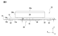
- FIG. 3 is a side view of the biometric information acquisition device.
- FIG. 4 is a top view of the biometric information acquisition device.
- the XYZ orthogonal coordinate system shown in the drawing is for facilitating understanding of the embodiments of the present disclosure, and does not limit the embodiments.
- the X-axis direction indicates the longitudinal direction of the biometric information acquisition device, the Y-axis direction indicates the lateral direction, and the Z-axis direction indicates the height direction.
- a biological information acquisition device 10 according to the present embodiment shown in FIG. 1 is a device that acquires a biological sound waveform generated from a living body as biological information.
- the biological information acquisition device 10 is configured to acquire body sounds, electrocardiographic waveforms, and body temperature as biological information.
- the body 12 of the biometric information acquisition device 10 is attached to the living body via the adhesive tape 14.
- the main body 12 of the biological information acquisition device 10 is plate-shaped and has a facing surface 12a that faces the living body when worn.
- the adhesive tape 14 is a double-sided tape, and the opposing surface 12a of the main body 12 is adhered to one adhesive surface 14a.
- the other adhesive surface 14b of the adhesive tape 14 is attached to the living body. That is, the facing surface 12a of the main body 12 of the biological information acquisition device 10 is attached to the living body via the adhesive tape 14 .
- the adhesive tape 14 is composed of a first tape having one surface that is a weakly viscous adhesive surface that can be attached to a living body and the other surface that is a smooth surface, and one surface that is the other surface of the first tape. and a second tape having a strong adhesive surface to be attached to the body 12 and having a strong adhesive surface to be attached to the main body 12 on the other surface.
- the body 12 of the biological information acquisition device 10 includes a first rigid body portion 16 that is substantially undeformable, second rigid body portions 18 and 20, and these rigid body portions 16, 18 and 20. and a deformable portion 22 that is supportively deformable.
- the first rigid section 16 and the second rigid sections 18 and 20 in the main body 12 of the biological information acquisition device 10 are made of a material such as hard resin that does not substantially deform.
- the deformable portion 22 is made of a softer (deformable) material than the rigid portion, such as soft resin, rubber, or cloth. In other words, the deformable portion 22 deforms more easily than the first rigid portion 16 and the second rigid portions 18 , 20 .
- being soft or easily deformable means having a relatively small elastic modulus such as Young's modulus or rigidity modulus.
- the facing surface 12a of the main body 12 of the biological information acquisition device 10 has high adhesiveness to the living body as compared with the case where the main body 12 is made only of non-deformable material such as hard resin. can adhere to. That is, even if the shape of the skin surface of the living body changes, the deformable portion 22 deforms accordingly, so that the facing surface 12a of the main body 12 can continue to be in close contact with the living body without gaps. By deforming the deformable portion 22, it is possible to reduce the impact on the main body 12 even when the adhesive tape is peeled off and dropped.
- the first rigid body part 16 is arranged in the center of the main body 12 in the longitudinal direction (X-axis direction).
- the second rigid portions 18 and 20 are arranged to face each other in the longitudinal direction with the first rigid portion 16 interposed therebetween. That is, the first rigid portion 16 is arranged between the second rigid portions 18 and 20 .
- the first rigid portion 16 is spaced apart from the second rigid portions 18 and 20, respectively.
- the portions sandwiched between the rigid portions 16 , 18 , 20 are deformation portions 22 .
- the second rigid parts 18 and 20 are provided at both ends of the main body 12 in the longitudinal direction. By separating the rigid body portions from each other in this manner, the main body 12 is easily deformed.
- the first rigid section 16 and the second rigid sections 18 and 20 of the main body 12 of the biological information acquisition device 10 are each provided with a plurality of components necessary for acquiring biological information.
- FIG. 5 is an upper exploded perspective view of the biological information acquisition device.
- FIG. 6 is a bottom exploded perspective view of the biological information acquisition device.
- FIG. 7 is a cross-sectional view of the biometric information acquisition device along line AA in FIG.
- FIG. 8 is a cross-sectional view of the biometric information acquisition device taken along line BB of FIG. 9 is a cross-sectional view of the biometric information acquisition device taken along line CC of FIG.
- the first rigid portion 16 has a substantially cylindrical shape with a bottom, and includes a bottom plate portion 16a and a height direction ( and an annular wall portion 16b extending in the Z-axis direction).
- the outer surface 16c of the bottom plate portion 16a of the first rigid portion 16 forms part of the facing surface 12a of the main body 12.
- a lid 24 is detachably attached to the first rigid body portion 16 .
- the lid body 24 includes a top plate portion 24a facing the bottom plate portion 16a of the first rigid portion 16 with a gap therebetween, and a height direction (Z an annular wall portion 24 b extending in the axial direction) and surrounding the annular wall portion 16 b of the first rigid portion 16 .
- the lid 24 is fixed to the first rigid portion 16 by rotating it in one rotational direction about the rotational center line extending in the height direction. When rotated in the other rotational direction, the lid 24 becomes detachable from the first rigid portion 16 .
- the first rigid section 16 is provided with a bioacoustic sensor 26 as a first biosensor and a control board 28 .
- the bioacoustic sensor 26 is a sensor that acquires a bioacoustic waveform of a living body, and its constituent elements are incorporated in the bottom plate portion 16 a of the first rigid body portion 16 .
- the bioacoustic sensor 26 includes a disk-shaped diaphragm 30 having a contact surface 30a that contacts the living body, and a disk-shaped diaphragm that detects the vibration of the diaphragm 30. of piezoelectric elements 32 .
- the vibration plate 30 and the piezoelectric element 32 are not limited to the disk shape, and may be square, rectangular, or other shapes.
- the bioacoustic sensor 26 is arranged between the diaphragm 30 and the piezoelectric element 32, includes an annular vibration transmission member 34 connecting the outer peripheral edge portion of the first surface 32a of the .
- the piezoelectric element 32 is attached via a double-faced tape 36 to the top surface of the protruding portion 16d of the first rigid portion 16 protruding toward the living body at the central portion of the second surface 32b.
- a signal line 32c of the piezoelectric element 32 passes through a through hole 16e formed in the bottom plate portion 16a of the first rigid portion 16 and is connected to the control board 28.
- FIG. As a result, when the diaphragm 30 vibrates, the piezoelectric element 32 as a whole bends and deforms, and the piezoelectric element 32 can detect vibration with high resolution.
- a thin film sheet 38 that covers and protects the bioacoustic sensor 26 is attached to the outer surface 16 c of the first rigid body portion 16 . Therefore, the contact surface 30a of the diaphragm 30 comes into contact with the living body through the film sheet 38. As shown in FIG.
- the bioacoustic sensor 26 is provided on the main body 12, that is, the first rigid body portion 16, so that at least a portion thereof protrudes from the facing surface 12a of the main body 12. Specifically, at least a portion of the diaphragm 30 of the bioacoustic sensor 26 protrudes from the facing surface 12a of the main body 12 .
- a contact surface 30a is provided at the distal end of the projecting portion.
- the contact surface 30a of the diaphragm 30 of the bioacoustic sensor 26 protruding from the facing surface 12a comes into strong contact with the living body.
- the diaphragm 30 vibrates as if in synchronism with the vibration of the living body.
- the piezoelectric element 32 can detect the vibration of the living body with high accuracy through the diaphragm 30 .
- the main body 12 of the biological information acquisition device 10 includes the deformation section 22 as described above. Therefore, even if the shape of the skin surface of the living body changes, the deformation portion 22 deforms accordingly, so that the facing surface 12a of the main body 12 can continue to be in close contact with the living body without gaps. As a result, the bioacoustic sensor 26 can continue to detect the vibration of the living body while maintaining high accuracy.
- the bioacoustic sensor 26 is provided on the first rigid body portion 16 instead of the deformable portion 22 of the main body 12 .
- the vibration of the part of the living body with which the bioacoustic sensor 26 contacts is transmitted to the bioacoustic sensor 26 with little loss.
- the bioacoustic sensor 26 is provided in the deformable portion 22, part of the vibrational energy of the living body is used to deform the deformable portion 22, and the vibration transmitted to the bioacoustic sensor 26 is attenuated. As a result, the vibration detection accuracy of the bioacoustic sensor 26 is lowered. Therefore, the bioacoustic sensor 26 is provided on the first rigid portion 16 instead of on the deformable portion 22 .
- the amount p of protrusion from the facing surface 12 a of the main body 12 of the bioacoustic sensor 26 is larger than the thickness t of the adhesive tape 14 . That is, the adhesive tape 14 has a thickness t that is smaller than the protrusion amount p of the bioacoustic sensor 26 .
- the adhesive tape 14 is formed with a through hole 14c through which the bioacoustic sensor 26 passes. A notch may be formed in the adhesive tape 14 instead of the through hole 14c. That is, the adhesive tape 14 is arranged so as to avoid the bioacoustic sensor 26 (so as not to overlap in plan view).
- control board 28 is accommodated within a space S defined by the first rigid body portion 16 and the lid body 24 .
- the control board 28 is a circular circuit board and has a battery 40 mounted on one surface thereof. The battery 40 can be replaced by removing the lid 24 from the first rigid portion 16 . 5 and 6, a flexible printed board 42 is connected to the control board 28. As shown in FIGS. Details of the control board 28 and the flexible printed board 42 will be described later.
- each of the second rigid parts 18 and 20 is provided with a second biosensor 44 .
- the second biosensor 44 is an electrocardiographic sensor that acquires an electrocardiographic waveform of a living body, and a plurality of electrodes 46 and 48 that contact the living body are attached to the second rigid body parts 18 and 20, respectively. is provided.
- the electrodes 46, 48 are attached to the second rigid parts 18, 20 via an annular double-sided tape 50, as shown in FIGS.
- the plurality of electrodes 46 and 48 of the electrocardiographic sensor 44 are preferably separated in order to obtain a good electrocardiogram waveform. Therefore, in the biological information acquisition device 10, the plurality of electrodes 46, 48 are provided on the main body 12 such that the bioacoustic sensor 26 is positioned therebetween. As a result, the biological information acquisition device 10 is miniaturized while separating the plurality of electrodes 46 and 48 as much as possible.
- each of the plurality of electrodes 46, 48 of the electrocardiographic sensor 44 has contact surfaces 46a, 48a that come into contact with the living body.
- the contact surfaces 46a and 48a are located on the anti-living body side with respect to the facing surface 12a of the main body 12.
- the contact surface 30a of the bioacoustic sensor 26 is located closer to the living body than the contact surfaces 46a and 48a.
- a conductive gel 52 is attached to the contact surfaces 46a, 48a of the plurality of electrodes 46, 48.
- FIG. Thereby, the contact surfaces 46 a and 48 a come into contact with the living body through the conductive gel 52 .
- the plurality of electrodes 46 and 48 are provided on the main body 12 so that the surface 52a of the conductive gel 52 that contacts the living body is substantially flush with the contact surface 30a of the bioacoustic sensor 26 .
- the adhesive tape 14 is formed with through holes 14d through which the conductive gel 52 passes.
- a notch may be formed in the adhesive tape 14 instead of the through hole 14d. That is, the adhesive tape 14 is arranged so as to avoid the conductive gel 52 (so as not to overlap in plan view).
- the distance from the facing surface 12a of the main body 12 to the contact surfaces 46a and 48a should be smaller than the distance from the facing surface 12a to the contact surface 30a of the bioacoustic sensor 26.
- the contact surface 30a of the bioacoustic sensor 26 can be brought into closer contact with the living body.
- the bioacoustic sensor 26 in order for the contact surface 30a of the bioacoustic sensor 26 to be in close contact with the living body, the bioacoustic sensor 26 should be provided with a plurality of second contact surfaces extending from the facing surface 12a of the main body 12 toward the living body. It is preferable that it protrudes greatly compared to the rigid parts 18 and 20 .
- surfaces 18a and 20a of the second rigid body portions 18 and 20, which face the living body constitute part of the facing surface 12a of the main body 12. As shown in FIG. Thereby, the contact surface 30a of the bioacoustic sensor 26 can be brought into closer contact with the living body.
- the biological information acquisition device 10 has a temperature sensor 54 that detects the temperature of the electrodes 46 .
- the temperature sensor 54 indirectly detects the body temperature of the living body by detecting the temperature of the electrode 46 in contact with the living body.
- the body temperature here is the temperature of the skin surface. If the temperature sensor is capable of measuring core body temperature, the body temperature is core body temperature.
- the temperature sensor 54 is connected to electrodes other than the electrodes 46 and 48, and can measure body temperature if it is in contact with the living body. For example, it may be in the bioacoustic sensor 26 .
- the electrocardiographic sensor 44 acquires an electrocardiographic waveform of the living body based on changes in potential difference between the electrodes 46 and 48 .
- FIG. 10 is a block diagram of the control system of the biometric information acquisition device.
- control board 28 of the biological information acquisition device 10 is provided with an amplifier/filter circuit 56 for amplifying and filtering the output value (voltage signal) from the bioacoustic sensor 26 (piezoelectric element 32). It is The control board 28 is also provided with, as a component of the electrocardiogram sensor 44, an arithmetic circuit 58 that calculates an electrocardiogram waveform based on the potential difference between the plurality of electrodes 46 and 48.
- the bioacoustic waveform from the bioacoustic sensor 26 processed by the amplifier/filter circuit 56 is analog-digital converted (A/D converted) by an MPU (microprocessor unit) 60 provided on the control board 28 .
- MPU microprocessor unit
- the electrocardiogram waveform calculated by the arithmetic circuit 58 and the body temperature from the temperature sensor 54 are also A/D converted by the MPU 60 .
- the MPU 60 is a unit that includes a CPU, memory, various circuits, and the like and executes various processes.
- the biological sound waveform data, electrocardiogram waveform data, and body temperature data created by A/D conversion by the MPU 60 are transmitted to an external device via the wireless communication module 62 provided on the control board 28 . These data are also stored in a storage device 64 such as a memory provided on the control board 28 .
- the wireless communication module 62 is a wireless communication module conforming to a wireless communication standard such as Bluetooth, for example, and transmits biosound waveform data, electrocardiographic waveform data, and temperature data to a mobile terminal, for example. Note that if the biological information acquisition device 10 has an output module such as a display capable of outputting biological sound waveform data and/or has a writer module that writes data to a storage medium such as a memory card, the wireless communication module may be omitted. is possible.
- the control board 28 is provided with an operation button 66 for starting or stopping acquisition of the biological sound waveform, electrocardiographic waveform, and body temperature.
- the operation button 66 is operated via a through hole 24c formed in the top plate portion 24a of the lid 24, as shown in FIG.
- the plurality of electrodes 46 and 48 of the electrocardiographic sensor 44 and the temperature sensor 54 are connected to the control board 28 via the flexible printed board 42.
- FIG. The flexible printed board 42 has a first connection end 42a connected to the control board 28, a second connection end 42b connected to the electrode 46, and a third connection end 42c connected to the electrode 48.
- the temperature sensor 54 is mounted on the second connection end 42b of the flexible printed circuit board 42.
- the plurality of electrodes 46 and 48 are electrically connected to the flexible printed circuit board 42 via spring terminals 68 provided at the second and third connecting ends 42b and 42c of the flexible printed circuit board 42, respectively.
- Electrical connection via the spring terminal 68 facilitates manufacture of the biological information acquisition device 10 compared to electrical connection via solder. Moreover, the electrodes 46 and 48 are urged toward the living body by the spring terminal 68, and the adhesion between the living body and the electrodes 46 and 48 is improved.
- the plurality of electrodes 46 and 48 of the electrocardiographic sensor 44 come into contact with the spring terminals 68 of the flexible printed circuit board 42 inside the second rigid parts 18 and 20 of the main body 12 . This maintains the contact.
- the electrodes 46 , 48 and the spring terminal 68 contact each other at the deformation portion 22 of the main body 12 , the deformation of the deformation portion 22 may break the contact.
- the electrodes 46,48 are in contact with the spring terminals 68 within the substantially non-deformable second rigid portions 18,20.
- a rigid cover plate 70 covering the second and third connection ends 42b, 42c of the flexible printed circuit board 42 in the second rigid parts 18, 20 is connected to the second rigid parts 18, 20 via double-sided tape 72. It is attached to the second and third connection ends 42b and 42c.
- the cover plate 70 functions as a retainer that receives the reaction force of the spring terminals 68 .
- the bottom plate portion 16a of the first rigid body portion 16 has a portion of the flexible printed circuit board 42 (control board) extending along the annular wall portion 16b. 28) are formed therein.
- FIG. 11 shows, as an example, a biological information acquisition device attached to a living body.
- the biometric information acquisition device 10 is attached to the body B of the living body via the adhesive tape 14. As shown in FIG. Then, when the operation button 66 is pressed, the biological information acquisition device 10 starts acquiring the biological sound waveform, the electrocardiogram waveform, and the body temperature as biological information, and transmits these data to the external device via the wireless communication module 62. . Acquisition of biometric information may be started after, for example, a switch provided on the mobile terminal is operated other than the operation button 66 . In FIG. 11, it is attached near the clavicle of the body, but it is not limited to this, and may be attached to the abdomen, back, neck, etc. according to the biological information to be acquired.
- biometric information acquisition device that can acquire biometric information with high accuracy by enhancing the close contact with the living body.
- the biological information acquisition device 10 acquires lung sound waveforms, electrocardiographic waveforms, and body temperature as biological information.
- a bioacoustic sensor may measure other body sounds produced by a living body, such as cardiac waveforms or intestinal peristaltic sounds. That is, the biometric information acquisition device according to the embodiment of the present disclosure is a device that acquires biometric information by contacting a living body.
- the electrocardiographic sensor 44 acquires an electrocardiographic waveform using two electrodes 46 and 48 .
- the number of electrodes is not limited to two.
- the electrocardiographic sensor has three electrodes.
- the body 12 of the biological information acquisition device 10 has the opposing surface 12a attached to the living body via the adhesive tape 14 having adhesive surfaces on both sides. can be pasted.
- this embodiment is not limited to this.
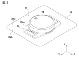
- FIG. 12 is a perspective view of the biometric information acquisition device showing another form of attachment to the living body.
- the biometric information acquisition device 10 is attached to the living body via an adhesive tape 114 .
- the adhesive tape 114 has a through hole 114a through which the cover 24 of the biometric information acquisition device 10 passes.
- One surface 114b of the adhesive tape 114 is an adhesive surface, and the other surface 114c is a smooth surface.
- the adhesive tape 114 may cover the entire biological information acquisition device 10 instead of providing the through hole 114a.
- the biological information acquisition device may be fixed to the living body by a band wrapped around the living body, clothes worn by the living body, or the like instead of the adhesive tape.
- the contour shape of the body 12 of the biological information acquisition device 10 that is, the contour shape of the deformable portion 22 corresponds to the height direction (Z axial direction), it has a generally rectangular shape.
- embodiments of the present disclosure are not limited to this.
- FIG. 13 is a schematic bottom view of a biometric information acquisition device according to another embodiment of the present disclosure.
- the deformable portion 122 of the main body 112 has the minimum necessary shape.
- the deformable portion 122 includes a central portion 122a that holds the first rigid body portion 116 provided with the bioacoustic sensor 126, and a second rigid body portion 122a that is provided with the electrodes 146 and 148 of the electrocardiographic sensor 144, respectively.
- outer portions 122b, 122c that hold portions 118, 120;
- the deformable portion 122 also includes a belt-like connecting portion 122d connecting the central portion 122a and the outer portion 122b, and a belt-like connecting portion 122e connecting the central portion 122a and the outer portion 122c.
- the strip-shaped connecting portions 122d and 122e are smaller than the central portion 122a and the outer portions 122b and 122c in size in the lateral direction (Y-axis direction) of the biological information acquisition device 110 . Therefore, it becomes easier for the outer portion to be displaced with respect to the central portion of the main body 112, that is, the main body 122 is more likely to deform. As a result, the facing surface 112a of the main body 122 is likely to come into close contact with the living body.
- the electrodes 46 and 48 of the electrocardiographic sensor 44 are rectangular when viewed in the height direction (Z-axis direction) of the biological information acquisition device 10. is.
- embodiments of the present disclosure are not limited to this.
- FIG. 14 is a schematic bottom view of a biometric information acquisition device according to yet another embodiment of the present disclosure.
- electrodes 246 and 248 of an electrocardiographic sensor 244 have a circular shape in the height direction (as viewed in the Z-axis direction). That is, it has a shape similar to that of the bioacoustic sensor 226 . It should be noted that the shape of the electrodes of the electrocardiographic sensor may be a shape other than a rectangular shape or a circular shape.
- the bioacoustic sensor 26 is arranged between the electrodes 46 and 48 . That is, the electrodes 46 and 48 are arranged such that their angular positions with respect to the bioacoustic sensor 26 differ by 180 degrees.
- embodiments of the present disclosure are not limited to this.
- FIG. 15 is a schematic bottom view of a biometric information acquisition device according to another embodiment of the present disclosure.
- the electrodes 346, 348 of the bioacoustic sensor 326 and the electrocardiographic sensor 344 are not aligned. Instead, the electrodes 346, 348 are positioned such that their angular positions with respect to the bioacoustic sensor 326 differ by 90 degrees. As such, the angular position of each of the electrodes 346, 348 with respect to the bioacoustic sensor 326 may be other angular positions. However, in order to obtain a good electrocardiographic waveform, it is preferable that the two electrodes of the electrocardiographic sensor are separated.
- the bioacoustic sensor 26 and the electrocardiographic sensor 44 are provided inseparably in the biological information acquisition device 10 .
- embodiments of the present disclosure are not limited to this.
- FIG. 16 is a schematic bottom view of a biometric information acquisition device according to yet another embodiment of the present disclosure.
- the main body includes a main part 412A including a first rigid section 416, a bioacoustic sensor 426, a control board, a battery, etc., and a heart.
- Optional parts 412B including electrodes 446 and 448 of electric sensor 444, second rigid body parts 418 and 420, and conductive gel can be separated.
- the main part 412A can be reused and the optional part 412B can be thrown away.
- the opposite method of use is also possible.
- body sounds can be acquired only with the main part 412A.
- the main part 412A and the option part 412B are provided with connectors for electrically connecting to each other. Moreover, when the optional part 412B is used up, the temperature sensor 454 for measuring the body temperature of the living body is provided in the main part 412A. The temperature sensor 454 measures the body temperature, for example, through the diaphragm of the bioacoustic sensor 426 that contacts the living body.
- the biological information acquisition device includes a main body having a facing surface that faces a living body when worn, and a main body that is attached to the main body so that at least a portion of the main body protrudes from the facing surface.
- a first biosensor provided and having a first contact surface that comes into contact with a living body; and a thin adhesive tape.
- a biological information acquisition device includes a main body having a facing surface that faces a living body when worn, and a first contact surface that is provided on the main body and contacts the living body. and a first biosensor, wherein the main body includes a first rigid part that supports the first biosensor, and a deformable part that supports the first rigid part and is deformable. It is what it is.
- the present disclosure is applicable to devices that are in close contact with a living body and acquire its biological information.
Landscapes
- Health & Medical Sciences (AREA)
- Life Sciences & Earth Sciences (AREA)
- Engineering & Computer Science (AREA)
- General Health & Medical Sciences (AREA)
- Veterinary Medicine (AREA)
- Heart & Thoracic Surgery (AREA)
- Medical Informatics (AREA)
- Molecular Biology (AREA)
- Surgery (AREA)
- Animal Behavior & Ethology (AREA)
- Biomedical Technology (AREA)
- Public Health (AREA)
- Physics & Mathematics (AREA)
- Biophysics (AREA)
- Pathology (AREA)
- Cardiology (AREA)
- Acoustics & Sound (AREA)
- Pulmonology (AREA)
- Physiology (AREA)
- Chemical & Material Sciences (AREA)
- Dispersion Chemistry (AREA)
- Signal Processing (AREA)
- Measuring And Recording Apparatus For Diagnosis (AREA)
Abstract
This biological information acquisition device comprises: a device body which has a counter surface that faces a biological body when the device is worn thereon; a first biological sensor which is provided to the device body so as to have at least a portion thereof protruding from the counter surface of the device body and which is provided with a first contact surface that comes into contact with the biological body; and a pressure-sensitive adhesive tape which is pasted to the counter surface of the device body and which has a thickness smaller than the amount of protrusion of the first biological sensor from the counter surface.
Description
本開示は、生体から発生する、例えば肺音(呼吸音、副雑音)や心音などの生体音を生体情報として取得する生体情報取得デバイスに関する。
The present disclosure relates to a biological information acquisition device that acquires body sounds such as lung sounds (breathing sounds, secondary murmurs) and heart sounds generated from a living body as biological information.
例えば、特許文献1には、生体情報として呼吸音波形、心音波形、心電波形などを取得する生体センサが開示されている。この生体センサは、基板と、基板を覆う被覆板と、基板と被覆板との間に配置された呼吸音波形を取得するための圧電素子を有する。
For example, Patent Document 1 discloses a biosensor that acquires a respiratory sound waveform, a heart sound waveform, an electrocardiogram waveform, etc. as biological information. The biosensor has a substrate, a cover plate covering the substrate, and a piezoelectric element for acquiring a respiratory sound waveform disposed between the substrate and the cover plate.
しかしながら、特許文献1に記載された生体センサの場合、圧電素子が設けられた基板の部分と生体との密着性が低い。そのため、圧電素子が呼吸音波形や心音波形を精度よく取得できない場合がある。
However, in the case of the biosensor described in Patent Document 1, the adhesion between the portion of the substrate provided with the piezoelectric element and the living body is low. Therefore, the piezoelectric element may not be able to accurately acquire the respiratory sound waveform and the heart sound waveform.
そこで、本開示は、生体との密着性を高めて生体情報を高い精度で取得することができる生体情報取得デバイスを提供することを課題とする。
Therefore, an object of the present disclosure is to provide a biometric information acquisition device capable of acquiring biometric information with high accuracy by enhancing close contact with a living body.
上記技術的課題を解決するために、本開示の一態様によれば、
装着時に生体に対向する対向面を備える本体と、
前記本体の前記対向面から少なくとも一部分が突出するように前記本体に設けられ、生体に接触する第1の接触面を備える第1の生体センサと、
前記本体の前記対向面に貼り付けられ、前記第1の生体センサの前記対向面からの突出量に比べて厚さが薄い粘着テープと、を有する、生体情報取得デバイスが提供される。 In order to solve the above technical problems, according to one aspect of the present disclosure,
a main body having a facing surface that faces a living body when worn;
a first biosensor provided on the main body so that at least a portion thereof protrudes from the facing surface of the main body, the first biosensor including a first contact surface that comes into contact with a living body;
and an adhesive tape that is attached to the facing surface of the main body and has a thickness smaller than the amount of protrusion of the first biosensor from the facing surface.
また、本開示の別態様によれば、
装着時に生体に対向する対向面を備える本体と、
前記本体に設けられ、生体に接触する第1の接触面を備える第1の生体センサと、を有し、
前記本体が、前記第1の生体センサを支持する第1の剛体部と、前記第1の剛体部を支持して変形可能な変形部とを含んでいる、生体情報取得デバイスが提供される。 Also, according to another aspect of the present disclosure,
a main body having a facing surface that faces a living body when worn;
a first biosensor provided on the main body and having a first contact surface that contacts a living body;
A biological information acquisition device is provided, wherein the main body includes a first rigid section that supports the first biological sensor, and a deformable section that supports the first rigid section and is deformable.
本開示によれば、生体との密着性を高めて生体情報を高い精度で取得することができる生体情報取得デバイスを提供することができる。
According to the present disclosure, it is possible to provide a biometric information acquisition device capable of acquiring biometric information with high accuracy by enhancing close contact with a living body.
本開示の一態様の生体音響センサは、装着時に生体に対向する対向面を備える本体と、前記本体の前記対向面から少なくとも一部分が突出するように前記本体に設けられ、生体に接触する第1の接触面を備える第1の生体センサと、前記本体の前記対向面に貼り付けられ、前記第1の生体センサの前記対向面からの突出量に比べて厚さが薄い粘着テープと、を有する。
A bioacoustic sensor according to one aspect of the present disclosure includes a main body including a facing surface that faces a living body when worn, and a first body that is provided in the main body so that at least a portion thereof protrudes from the facing face of the main body and contacts the living body. and an adhesive tape attached to the facing surface of the main body and having a thickness smaller than the amount of protrusion of the first biosensor from the facing surface. .
この態様によれば、生体との密着性を高めて生体情報を高い精度で取得することができる生体情報取得デバイスを提供することができる。
According to this aspect, it is possible to provide a biometric information acquisition device that can acquire biometric information with high accuracy by enhancing the close contact with the living body.
例えば、前記第1の生体センサが、前記第1の接触面を備えて前記本体の前記対向面から少なくとも一部分が突出する振動板と、前記振動板の振動を検出する圧電素子とを含み、生体の発する音を測定する生体音響センサであってもよい。
For example, the first biosensor includes a diaphragm having the first contact surface and at least a portion of which protrudes from the facing surface of the main body, and a piezoelectric element for detecting vibration of the diaphragm. It may be a bioacoustic sensor that measures the sound emitted by.
例えば、生体情報取得デバイスが、前記対向面から少なくとも一部分が突出するように前記本体に設けられ、生体に接触する第2の接触面を備える第2の生体センサをさらに有し、前記対向面から前記第1の生体センサの第1の接触面までの距離が、前記対向面から前記第2の生体センサの第2の接触面までの距離に比べて大きくしてもよい。
For example, the biometric information acquisition device further includes a second biosensor provided on the main body so that at least a portion protrudes from the facing surface, the second biosensor having a second contact surface that contacts the living body, A distance to the first contact surface of the first biosensor may be greater than a distance from the facing surface to the second contact surface of the second biosensor.
例えば、前記第2の生体センサが、前記第2の接触面をそれぞれ備える複数の電極を含み、生体の心電波形を取得する心電センサであって、前記第2の生体センサの前記複数の電極が、前記複数の電極の間に前記第1の生体センサが位置するように、前記本体に設けられてもよい。
For example, the second biosensor is an electrocardiographic sensor that includes a plurality of electrodes each having the second contact surface and acquires an electrocardiographic waveform of a living body, and the plurality of electrodes of the second biosensor Electrodes may be provided on the body such that the first biosensor is positioned between the plurality of electrodes.
例えば、前記第2の生体センサの前記複数の電極の前記第2の接触面が、導電性ゲルを介して生体に接触し、生体と接触する前記導電性ゲルの表面が前記第1の生体センサの前記第1の接触面と実質的に同一平面に位置するように、前記複数の電極が前記本体に設けられてもよい。
For example, the second contact surfaces of the plurality of electrodes of the second biosensor are in contact with a living body through a conductive gel, and the surface of the conductive gel in contact with the living body is the first biosensor. The plurality of electrodes may be provided on the body so as to lie substantially coplanar with the first contact surface of the.
例えば、前記本体が、前記第1の生体センサを支持する第1の剛体部、前記第2の生体センサの前記複数の電極それぞれを支持する複数の第2の剛体部、および前記第1の剛体部と前記複数の第2の剛体部とを支持し、前記第1の剛体部と前記複数の第2の剛体部より軟質な変形部を含んでもよい。
For example, the main body includes a first rigid section that supports the first biosensor, a plurality of second rigid sections that respectively support the plurality of electrodes of the second biosensor, and the first rigid body. and a deformable portion that supports the portion and the plurality of second rigid portions and is softer than the first rigid portion and the plurality of second rigid portions.
例えば、前記第1の生体センサが、前記本体の前記対向面から生体側に、前記複数の第2の剛体部に比べて大きく突出してもよい。
For example, the first biosensor may protrude from the facing surface of the main body toward the living body to a greater extent than the plurality of second rigid bodies.
例えば、生体情報取得デバイスが、生体の体温を取得する温度センサをさらに有し、前記温度センサが、前記複数の電極の少なくとも一つを介して体温を取得してもよい。
For example, the biological information acquisition device may further include a temperature sensor that acquires body temperature, and the temperature sensor may acquire body temperature via at least one of the plurality of electrodes.
本開示の別態様の生体情報取得デバイスは、装着時に生体に対向する対向面を備える本体と、前記本体に設けられ、生体に接触する第1の接触面を備える第1の生体センサと、を有し、前記本体が、前記第1の生体センサを支持する第1の剛体部と、前記第1の剛体部を支持し、前記第1の剛体部より軟質な変形部とを含んでいる。
A biological information acquisition device according to another aspect of the present disclosure includes a main body including a facing surface that faces a living body when worn, and a first biosensor provided on the main body and provided with a first contact surface that contacts the living body. The main body includes a first rigid portion that supports the first biosensor, and a deformable portion that supports the first rigid portion and is softer than the first rigid portion.
この態様によれば、生体との密着性を高めて生体情報を高い精度で取得することができる生体情報取得デバイスを提供することができる。
According to this aspect, it is possible to provide a biometric information acquisition device that can acquire biometric information with high accuracy by enhancing the close contact with the living body.
例えば、前記第1の生体センサが、前記第1の接触面を備える振動板と、前記振動板の振動を検出する圧電素子とを含み、生体の発する音を測定する生体音響センサであってもよい。
For example, even if the first biosensor is a bioacoustic sensor that includes a diaphragm having the first contact surface and a piezoelectric element that detects vibration of the diaphragm, and that measures the sound emitted by a living body. good.
例えば、生体情報取得デバイスが、生体に接触する第2の接触面を備える第2の生体センサをさらに有し、前記本体が、前記第2の生体センサを支持する第2の剛体部を含んでもよい。
For example, the biometric information acquisition device may further include a second biosensor having a second contact surface that contacts a living body, and the main body may include a second rigid portion that supports the second biosensor. good.
例えば、前記第2の生体センサが、前記第2の接触面をそれぞれ備える複数の電極を含み、生体の心電波形を取得する心電センサであって、前記第2の剛体部が複数あって、前記第2の生体センサの前記複数の電極が、前記複数の第2の剛体部に設けられてもよい。なお、第2電極は矩形形状に限らず、円形状であってもよい。
For example, the second biosensor is an electrocardiographic sensor that includes a plurality of electrodes each having the second contact surface and acquires an electrocardiogram waveform of a living body, and the second rigid body portion includes a plurality of , the plurality of electrodes of the second biosensor may be provided on the plurality of second rigid bodies. In addition, the second electrode is not limited to a rectangular shape, and may be circular.
例えば、前記複数の第2の剛体部の間に、前記第1の剛体部が配置されてもよい。
For example, the first rigid section may be arranged between the plurality of second rigid sections.
例えば、前記第1の剛体部が、前記複数の第2の剛体部それぞれに対して距離をあけてもよい。
For example, the first rigid body may be spaced apart from each of the plurality of second rigid bodies.
以下、本開示の実施の形態について、図面を参照しながら説明する。
Hereinafter, embodiments of the present disclosure will be described with reference to the drawings.
図1は、本開示の実施の一実施の形態に係る生体情報取得デバイスの上方斜視図である。また、図2は、生体情報取得デバイスの下方斜視図である。さらに、図3は、生体情報取得デバイスの側面図である。さらにまた、図4は、生体情報取得デバイスの上面図である。なお、図に示すX-Y-Z直交座標系は、本開示の実施の形態の理解を容易にするためのものであって、実施の形態を限定するものではない。X軸方向は生体情報取得デバイスの長手方向を示し、Y軸方向は短手方向を示し、Z軸方向は高さ方向を示している。
FIG. 1 is an upper perspective view of a biological information acquisition device according to one embodiment of the present disclosure. Also, FIG. 2 is a bottom perspective view of the biometric information acquisition device. Furthermore, FIG. 3 is a side view of the biometric information acquisition device. Furthermore, FIG. 4 is a top view of the biometric information acquisition device. The XYZ orthogonal coordinate system shown in the drawing is for facilitating understanding of the embodiments of the present disclosure, and does not limit the embodiments. The X-axis direction indicates the longitudinal direction of the biometric information acquisition device, the Y-axis direction indicates the lateral direction, and the Z-axis direction indicates the height direction.
図1に示す本実施の形態に係る生体情報取得デバイス10は、生体情報として生体から発生する生体音波形を取得するデバイスである。
A biological information acquisition device 10 according to the present embodiment shown in FIG. 1 is a device that acquires a biological sound waveform generated from a living body as biological information.
また、本実施の形態の場合、生体情報取得デバイス10は、生体情報として、生体音、心電波形と体温とを取得するように構成されている。
In addition, in the case of the present embodiment, the biological information acquisition device 10 is configured to acquire body sounds, electrocardiographic waveforms, and body temperature as biological information.
図1~図4に示すように、本実施の形態の場合、生体情報取得デバイス10の本体12は、粘着テープ14を介して生体に装着される。
As shown in FIGS. 1 to 4, in the case of this embodiment, the body 12 of the biometric information acquisition device 10 is attached to the living body via the adhesive tape 14. FIG.
具体的には、図2に示すように、生体情報取得デバイス10の本体12は、プレート状であって、装着時に生体に対向する対向面12aを備える。本実施の形態の場合、粘着テープ14は、両面テープであって、一方の粘着面14aに本体12の対向面12aが接着される。粘着テープ14の他方の粘着面14bは生体に貼り付けられる。すなわち、生体情報取得デバイス10の本体12の対向面12aは、粘着テープ14を介して、生体に貼り付けられる。なお、粘着テープ14は、一方の表面が生体に貼り付けられる弱粘性の粘着面であって他方の表面が平滑面である第1のテープと、一方の表面が第1のテープの他方の表面に貼り付けられる強粘性の粘着面であって他方の表面が本体12に貼り付けられる強粘着性の粘着面である第2のテープとから構成されてもよい。
Specifically, as shown in FIG. 2, the main body 12 of the biological information acquisition device 10 is plate-shaped and has a facing surface 12a that faces the living body when worn. In the case of this embodiment, the adhesive tape 14 is a double-sided tape, and the opposing surface 12a of the main body 12 is adhered to one adhesive surface 14a. The other adhesive surface 14b of the adhesive tape 14 is attached to the living body. That is, the facing surface 12a of the main body 12 of the biological information acquisition device 10 is attached to the living body via the adhesive tape 14 . The adhesive tape 14 is composed of a first tape having one surface that is a weakly viscous adhesive surface that can be attached to a living body and the other surface that is a smooth surface, and one surface that is the other surface of the first tape. and a second tape having a strong adhesive surface to be attached to the body 12 and having a strong adhesive surface to be attached to the main body 12 on the other surface.
本実施の形態の場合、生体情報取得デバイス10の本体12は、実質的に変形しない第1の剛体部16と、第2の剛体部18、20と、これらの剛体部16、18、20を支持して変形可能な変形部22とを含んでいる。
In the case of the present embodiment, the body 12 of the biological information acquisition device 10 includes a first rigid body portion 16 that is substantially undeformable, second rigid body portions 18 and 20, and these rigid body portions 16, 18 and 20. and a deformable portion 22 that is supportively deformable.
本実施の形態の場合、生体情報取得デバイス10の本体12における第1の剛体部16および第2の剛体部18、20は、例えば硬質樹脂などの実質的に変形しない材料から作製されている。これに対して変形部22は、例えば軟質樹脂、ゴム、布など、剛体部より軟質な(変形可能な)材料から作成されている。言い換えれば、変形部22は、第1の剛体部16および第2の剛体部18、20よりも変形しやすい。ここで、軟質である、又は変形しやすい、とは、ヤング率或いは剛性率などの弾性率が比較的に小さい、ことを指す。
In the case of the present embodiment, the first rigid section 16 and the second rigid sections 18 and 20 in the main body 12 of the biological information acquisition device 10 are made of a material such as hard resin that does not substantially deform. On the other hand, the deformable portion 22 is made of a softer (deformable) material than the rigid portion, such as soft resin, rubber, or cloth. In other words, the deformable portion 22 deforms more easily than the first rigid portion 16 and the second rigid portions 18 , 20 . Here, being soft or easily deformable means having a relatively small elastic modulus such as Young's modulus or rigidity modulus.
このような本体12の構成によれば、生体情報取得デバイス10の本体12の対向面12aは、硬質樹脂などの変形しない材料のみから本体12が作製される場合に比べて、高い密着性で生体に密着することができる。すなわち、生体の皮膚表面の形状が変化してもそれに合わせて変形部22が変形することにより、本体12の対向面12aは隙間なく生体に密着し続けることができる。変形部22が変形することで、粘着テープが剥がれて落ちた場合においても本体12への衝撃を減らすことができる。
According to such a configuration of the main body 12, the facing surface 12a of the main body 12 of the biological information acquisition device 10 has high adhesiveness to the living body as compared with the case where the main body 12 is made only of non-deformable material such as hard resin. can adhere to. That is, even if the shape of the skin surface of the living body changes, the deformable portion 22 deforms accordingly, so that the facing surface 12a of the main body 12 can continue to be in close contact with the living body without gaps. By deforming the deformable portion 22, it is possible to reduce the impact on the main body 12 even when the adhesive tape is peeled off and dropped.
生体情報取得デバイス10の本体12において、第1の剛体部16は、本体12の長手方向(X軸方向)の中央に配置されている。第2の剛体部18、20それぞれは、第1の剛体部16を挟んで長手方向に互いに対向するように配置されている。すなわち、第2の剛体部18、20の間に第1の剛体部16が配置されている。また、本実施の形態の場合、第1の剛体部16は、第2の剛体部18、20それぞれに対して距離をあけている。また、各剛体部16、18、20の間に挟まれる部分は変形部22となっている。また、第2の剛体部18、20は、本体12の長手方向の両端それぞれに設けられている。このように剛体部同士が離れることにより、本体12は変形しやすくなる。
In the main body 12 of the biological information acquisition device 10, the first rigid body part 16 is arranged in the center of the main body 12 in the longitudinal direction (X-axis direction). The second rigid portions 18 and 20 are arranged to face each other in the longitudinal direction with the first rigid portion 16 interposed therebetween. That is, the first rigid portion 16 is arranged between the second rigid portions 18 and 20 . In addition, in the case of this embodiment, the first rigid portion 16 is spaced apart from the second rigid portions 18 and 20, respectively. Also, the portions sandwiched between the rigid portions 16 , 18 , 20 are deformation portions 22 . The second rigid parts 18 and 20 are provided at both ends of the main body 12 in the longitudinal direction. By separating the rigid body portions from each other in this manner, the main body 12 is easily deformed.
生体情報取得デバイス10の本体12における第1の剛体部16および第2の剛体部18、20それぞれには、生体情報の取得に必要な複数の構成要素が設けられている。
The first rigid section 16 and the second rigid sections 18 and 20 of the main body 12 of the biological information acquisition device 10 are each provided with a plurality of components necessary for acquiring biological information.
図5は、生体情報取得デバイスの上方分解斜視図である。また、図6は、生体情報取得デバイスの下方分解斜視図である。さらに、図7は、図4のA-A線に沿った生体情報取得デバイスの断面図である。さらにまた、図8は、図4のB-B線に沿った生体情報取得デバイスの断面図である。そして、図9は、図4のC-C線に沿った生体情報取得デバイスの断面図である。
FIG. 5 is an upper exploded perspective view of the biological information acquisition device. Also, FIG. 6 is a bottom exploded perspective view of the biological information acquisition device. Furthermore, FIG. 7 is a cross-sectional view of the biometric information acquisition device along line AA in FIG. Furthermore, FIG. 8 is a cross-sectional view of the biometric information acquisition device taken along line BB of FIG. 9 is a cross-sectional view of the biometric information acquisition device taken along line CC of FIG.
図5および図9に示すように、本実施の形態の場合、第1の剛体部16は、概略有底筒状であって、底板部16aと、底板部16aの外周縁から高さ方向(Z軸方向)に延在する環状壁部16bとを備える。本実施の形態の場合、第1の剛体部16の底板部16aの外側面16cは、本体12の対向面12aの一部を構成する。
As shown in FIGS. 5 and 9, in the case of the present embodiment, the first rigid portion 16 has a substantially cylindrical shape with a bottom, and includes a bottom plate portion 16a and a height direction ( and an annular wall portion 16b extending in the Z-axis direction). In the case of the present embodiment, the outer surface 16c of the bottom plate portion 16a of the first rigid portion 16 forms part of the facing surface 12a of the main body 12. As shown in FIG.
また、第1の剛体部16には、着脱可能に蓋体24が取り付けられる。図9に示すように、蓋体24は、第1の剛体部16の底板部16aに対して間隔をあけて対向する天板部24aと、天板部24aの外周縁から高さ方向(Z軸方向)に延在して第1の剛体部16の環状壁部16bを囲む環状壁部24bとを備える。本実施の形態の場合、蓋体24は、高さ方向に延在する回転中心線を中心にして一方の回転方向に回転させることにより、第1の剛体部16に対して固定される。他方の回転方向に回転させると、蓋体24は、第1の剛体部16に対して取り外し可能な状態になる。
A lid 24 is detachably attached to the first rigid body portion 16 . As shown in FIG. 9, the lid body 24 includes a top plate portion 24a facing the bottom plate portion 16a of the first rigid portion 16 with a gap therebetween, and a height direction (Z an annular wall portion 24 b extending in the axial direction) and surrounding the annular wall portion 16 b of the first rigid portion 16 . In the case of the present embodiment, the lid 24 is fixed to the first rigid portion 16 by rotating it in one rotational direction about the rotational center line extending in the height direction. When rotated in the other rotational direction, the lid 24 becomes detachable from the first rigid portion 16 .
図9に示すように、第1の剛体部16には、第1の生体センサとしての生体音響センサ26と、制御基板28とが設けられている。
As shown in FIG. 9, the first rigid section 16 is provided with a bioacoustic sensor 26 as a first biosensor and a control board 28 .
生体音響センサ26は、生体の生体音波形を取得するセンサであって、その構成要素が第1の剛体部16の底板部16aに組み込まれている。
The bioacoustic sensor 26 is a sensor that acquires a bioacoustic waveform of a living body, and its constituent elements are incorporated in the bottom plate portion 16 a of the first rigid body portion 16 .
本実施の形態の場合、図5および図6に示すように、生体音響センサ26は、生体と接触する接触面30aを備える円盤状の振動板30と、振動板30の振動を検出する円盤状の圧電素子32とを含んでいる。なお、振動板30および圧電素子32は、円盤状に限らず、正方形状、矩形状などの他の形状であってもよい。
In the case of the present embodiment, as shown in FIGS. 5 and 6, the bioacoustic sensor 26 includes a disk-shaped diaphragm 30 having a contact surface 30a that contacts the living body, and a disk-shaped diaphragm that detects the vibration of the diaphragm 30. of piezoelectric elements 32 . Note that the vibration plate 30 and the piezoelectric element 32 are not limited to the disk shape, and may be square, rectangular, or other shapes.
さらに、本実施の形態の場合、図5、図6、および図9に示すように、生体音響センサ26は、振動板30と圧電素子32との間に配置され、振動板30と圧電素子32の第1の表面32aの外周縁部分とを接続する環状の振動伝達部材34を含んでいる。圧電素子32は、その第2の表面32bの中央部分で、生体側に向かって隆起する第1の剛体部16の隆起部16dの頂面に両面テープ36を介して貼り付けられている。圧電素子32の信号線32cは、第1の剛体部16の底板部16aに形成された貫通穴16eを通過して制御基板28に接続されている。これにより、振動板30が振動すると、圧電素子32全体がたわみ変形し、圧電素子32は高解像度に振動を検出することができる。
Furthermore, in the case of this embodiment, as shown in FIGS. 5, 6, and 9, the bioacoustic sensor 26 is arranged between the diaphragm 30 and the piezoelectric element 32, includes an annular vibration transmission member 34 connecting the outer peripheral edge portion of the first surface 32a of the . The piezoelectric element 32 is attached via a double-faced tape 36 to the top surface of the protruding portion 16d of the first rigid portion 16 protruding toward the living body at the central portion of the second surface 32b. A signal line 32c of the piezoelectric element 32 passes through a through hole 16e formed in the bottom plate portion 16a of the first rigid portion 16 and is connected to the control board 28. As shown in FIG. As a result, when the diaphragm 30 vibrates, the piezoelectric element 32 as a whole bends and deforms, and the piezoelectric element 32 can detect vibration with high resolution.
なお、本実施の形態の場合、生体音響センサ26を覆って保護する薄いフィルムシート38が、第1の剛体部16の外側面16cに貼り付けられている。したがって、振動板30の接触面30aは、フィルムシート38を介して生体に接触する。
In addition, in the case of the present embodiment, a thin film sheet 38 that covers and protects the bioacoustic sensor 26 is attached to the outer surface 16 c of the first rigid body portion 16 . Therefore, the contact surface 30a of the diaphragm 30 comes into contact with the living body through the film sheet 38. As shown in FIG.
本実施の形態の場合、生体音響センサ26は、少なくとも一部分が本体12の対向面12aから突出するように、本体12、すなわち第1の剛体部16に設けられている。具体的には、生体音響センサ26の振動板30の少なくとも一部分が本体12の対向面12aから突出している。その突出した部分の遠位端に、接触面30aが設けられている。これにより、生体音響センサ26(その振動板30)の接触面30aと生体とが高い密着性で密着し、生体から発生した振動(生体音)を生体音響センサ26は高い精度で取得することができる。
In the case of the present embodiment, the bioacoustic sensor 26 is provided on the main body 12, that is, the first rigid body portion 16, so that at least a portion thereof protrudes from the facing surface 12a of the main body 12. Specifically, at least a portion of the diaphragm 30 of the bioacoustic sensor 26 protrudes from the facing surface 12a of the main body 12 . A contact surface 30a is provided at the distal end of the projecting portion. As a result, the contact surface 30a of the bioacoustic sensor 26 (the diaphragm 30 thereof) and the living body are in close contact with each other with high adhesion, and the bioacoustic sensor 26 can acquire vibrations (body sounds) generated from the living body with high accuracy. can.
具体的に説明すると、粘着テープ14を介して本体12の対向面12aが生体に密着すると、その対向面12aから突出している生体音響センサ26の振動板30の接触面30aが生体に強く密着する(生体音響センサ26が対向面12aから突出していない場合に比べて)。それにより、生体の振動にあたかも同期するように、振動板30が振動する。圧電素子32は、振動板30を介して、生体の振動を高い精度で検出することができる。
More specifically, when the facing surface 12a of the main body 12 comes into close contact with the living body through the adhesive tape 14, the contact surface 30a of the diaphragm 30 of the bioacoustic sensor 26 protruding from the facing surface 12a comes into strong contact with the living body. (Compared to the case where the bioacoustic sensor 26 does not protrude from the facing surface 12a). As a result, the diaphragm 30 vibrates as if in synchronism with the vibration of the living body. The piezoelectric element 32 can detect the vibration of the living body with high accuracy through the diaphragm 30 .
さらに言えば、本実施の形態の場合、上述したように、生体情報取得デバイス10の本体12は、変形部22を含んでいる。そのため、生体の皮膚表面の形状が変化してもそれに合わせて変形部22が変形することにより、本体12の対向面12aは隙間なく生体に密着し続けることができる。その結果、生体音響センサ26は、生体の振動を、高い精度を維持しながら検出し続けることができる。
Furthermore, in the case of the present embodiment, the main body 12 of the biological information acquisition device 10 includes the deformation section 22 as described above. Therefore, even if the shape of the skin surface of the living body changes, the deformation portion 22 deforms accordingly, so that the facing surface 12a of the main body 12 can continue to be in close contact with the living body without gaps. As a result, the bioacoustic sensor 26 can continue to detect the vibration of the living body while maintaining high accuracy.
なお、本実施の形態の場合、生体音響センサ26は、本体12の変形部22ではなく、第1の剛体部16に設けられている。それにより、生体音響センサ26の接触する生体の部分の振動が、少ない損失で生体音響センサ26に伝達される。
In addition, in the case of the present embodiment, the bioacoustic sensor 26 is provided on the first rigid body portion 16 instead of the deformable portion 22 of the main body 12 . As a result, the vibration of the part of the living body with which the bioacoustic sensor 26 contacts is transmitted to the bioacoustic sensor 26 with little loss.
これと異なり、生体音響センサ26が変形部22に設けられている場合、生体の振動エネルギの一部が変形部22の変形に使用され、生体音響センサ26に伝わる振動が減衰する。その結果、生体音響センサ26の振動検出精度が低下する。したがって、生体音響センサ26は、変形部22ではなく第1の剛体部16に設けられている。
In contrast, when the bioacoustic sensor 26 is provided in the deformable portion 22, part of the vibrational energy of the living body is used to deform the deformable portion 22, and the vibration transmitted to the bioacoustic sensor 26 is attenuated. As a result, the vibration detection accuracy of the bioacoustic sensor 26 is lowered. Therefore, the bioacoustic sensor 26 is provided on the first rigid portion 16 instead of on the deformable portion 22 .
また、本実施の形態の場合、図3に示すように、生体情報取得デバイス10の本体12の対向面12aには、粘着テープ14が貼り付けられる。そのため、生体音響センサ26本体12の対向面12aからの突出量pは、粘着テープ14の厚さtに比べて大きい。すなわち、粘着テープ14は、生体音響センサ26の突出量pに比べて小さい厚さtを備えている。なお、図5および図6に示すように。粘着テープ14には、生体音響センサ26が通過する貫通穴14cが形成されている。なお、貫通穴14cに代わって、切り欠きが粘着テープ14に形成されてもよい。すなわち、粘着テープ14は、生体音響センサ26を避けるように(平面視で重ならないように)配置されている。
Also, in the case of the present embodiment, as shown in FIG. Therefore, the amount p of protrusion from the facing surface 12 a of the main body 12 of the bioacoustic sensor 26 is larger than the thickness t of the adhesive tape 14 . That is, the adhesive tape 14 has a thickness t that is smaller than the protrusion amount p of the bioacoustic sensor 26 . In addition, as shown in FIG.5 and FIG.6. The adhesive tape 14 is formed with a through hole 14c through which the bioacoustic sensor 26 passes. A notch may be formed in the adhesive tape 14 instead of the through hole 14c. That is, the adhesive tape 14 is arranged so as to avoid the bioacoustic sensor 26 (so as not to overlap in plan view).
図9に示すように、制御基板28は、第1の剛体部16と蓋体24とによって画定される空間S内に収容されている。本実施の形態の場合、制御基板28は、円形状の回路基板であって、一方の表面にバッテリ40が搭載されている。バッテリ40は、蓋体24を第1の剛体部16から取り外すことにより、交換可能である。また、図5および図6に示すように、制御基板28には、フレキシブルプリント基板42が接続されている。制御基板28およびフレキシブルプリント基板42の詳細については後述する。
As shown in FIG. 9, the control board 28 is accommodated within a space S defined by the first rigid body portion 16 and the lid body 24 . In the case of this embodiment, the control board 28 is a circular circuit board and has a battery 40 mounted on one surface thereof. The battery 40 can be replaced by removing the lid 24 from the first rigid portion 16 . 5 and 6, a flexible printed board 42 is connected to the control board 28. As shown in FIGS. Details of the control board 28 and the flexible printed board 42 will be described later.
図7に示すように、第2の剛体部18、20それぞれには、第2の生体センサ44が設けられている。具体的には、第2の生体センサ44は、生体の心電波形を取得する心電センサであって、その生体に接触する複数の電極46、48それぞれが第2の剛体部18、20に設けられている。電極46、48は、図5および図6に示すように、環状の両面テープ50を介して、第2の剛体部18、20に貼り付けられている。
As shown in FIG. 7, each of the second rigid parts 18 and 20 is provided with a second biosensor 44 . Specifically, the second biosensor 44 is an electrocardiographic sensor that acquires an electrocardiographic waveform of a living body, and a plurality of electrodes 46 and 48 that contact the living body are attached to the second rigid body parts 18 and 20, respectively. is provided. The electrodes 46, 48 are attached to the second rigid parts 18, 20 via an annular double-sided tape 50, as shown in FIGS.
なお、心電センサ44の複数の電極46、48は、良好な心電波形を取得するためには、離れているのが好ましい。そのため、生体情報取得デバイス10においては、複数の電極46、48は、その間に生体音響センサ26が位置するように、本体12に設けられている。その結果、複数の電極46、48を可能な限り離しつつ、生体情報取得デバイス10を小型化している。
It should be noted that the plurality of electrodes 46 and 48 of the electrocardiographic sensor 44 are preferably separated in order to obtain a good electrocardiogram waveform. Therefore, in the biological information acquisition device 10, the plurality of electrodes 46, 48 are provided on the main body 12 such that the bioacoustic sensor 26 is positioned therebetween. As a result, the biological information acquisition device 10 is miniaturized while separating the plurality of electrodes 46 and 48 as much as possible.
図7に示すように、心電センサ44の複数の電極46、48それぞれは、生体に接触する接触面46a、48aを備える。本実施の形態の場合、接触面46a、48aは、本体12の対向面12aに対して反生体側に位置する。その結果、生体音響センサ26の接触面30aが、接触面46a、48aに比べて生体側に位置する。
As shown in FIG. 7, each of the plurality of electrodes 46, 48 of the electrocardiographic sensor 44 has contact surfaces 46a, 48a that come into contact with the living body. In the case of this embodiment, the contact surfaces 46a and 48a are located on the anti-living body side with respect to the facing surface 12a of the main body 12. As shown in FIG. As a result, the contact surface 30a of the bioacoustic sensor 26 is located closer to the living body than the contact surfaces 46a and 48a.
そのために、本実施の形態の場合、図7に示すように、複数の電極46、48の接触面46a、48aには、導電性ゲル52が貼り付けられている。それにより、接触面46a、48aは、導電性ゲル52を介して生体に接触する。生体と接触する導電性ゲル52の表面52aが生体音響センサ26の接触面30aと実質的に同一平面に位置するように、複数の電極46、48は本体12に設けられている。すなわち、本体12の対向面12aから導電性ゲル52の表面52aまでの距離(すなわち高さ方向(Z軸方向)の距離)と、対向面12aから生体音響センサ26の接触面30aまでの距離が等しくされている。これにより、生体音響センサ26の接触面30aが生体により密着することができる。なお、本実施の形態の場合、図5および図6に示すように、粘着テープ14には、導電性ゲル52が通過する貫通穴14dが形成されている。なお、貫通穴14dに代わって、切り欠きが粘着テープ14に形成されてもよい。すなわち、粘着テープ14は、導電性ゲル52を避けるように(平面視で重ならないように)配置されている。
Therefore, in the case of the present embodiment, as shown in FIG. 7, a conductive gel 52 is attached to the contact surfaces 46a, 48a of the plurality of electrodes 46, 48. FIG. Thereby, the contact surfaces 46 a and 48 a come into contact with the living body through the conductive gel 52 . The plurality of electrodes 46 and 48 are provided on the main body 12 so that the surface 52a of the conductive gel 52 that contacts the living body is substantially flush with the contact surface 30a of the bioacoustic sensor 26 . That is, the distance from the opposing surface 12a of the main body 12 to the surface 52a of the conductive gel 52 (that is, the distance in the height direction (Z-axis direction)) and the distance from the opposing surface 12a to the contact surface 30a of the bioacoustic sensor 26 are are made equal. Thereby, the contact surface 30a of the bioacoustic sensor 26 can be brought into closer contact with the living body. In this embodiment, as shown in FIGS. 5 and 6, the adhesive tape 14 is formed with through holes 14d through which the conductive gel 52 passes. A notch may be formed in the adhesive tape 14 instead of the through hole 14d. That is, the adhesive tape 14 is arranged so as to avoid the conductive gel 52 (so as not to overlap in plan view).
なお、導電性ゲル52を介することなく、電極46、48の接触面46a、48aが生体に直接接触する場合、本体12の対向面12aから接触面46a、48aまでの距離(すなわち高さ方向(Z軸方向)の距離)を、対向面12aから生体音響センサ26の接触面30aまでの距離に比べて小さくするのがよい。これにより、生体音響センサ26の接触面30aが生体により密着することができる。
When the contact surfaces 46a and 48a of the electrodes 46 and 48 come into direct contact with the living body without the conductive gel 52 interposed therebetween, the distance from the facing surface 12a of the main body 12 to the contact surfaces 46a and 48a (that is, in the height direction ( Z-axis direction)) should be smaller than the distance from the facing surface 12a to the contact surface 30a of the bioacoustic sensor 26. FIG. Thereby, the contact surface 30a of the bioacoustic sensor 26 can be brought into closer contact with the living body.
さらに言えば、図7に示すように、生体音響センサ26の接触面30aが生体に密着するためには、生体音響センサ26は、本体12の対向面12aから生体側に、複数の第2の剛体部18、20に比べて大きく突出しているのがよい。本実施の形態の場合、第2の剛体部18、20それぞれは、生体に対向する表面18a、20aが本体12の対向面12aの一部を構成している。これにより、生体音響センサ26の接触面30aが生体により密着することができる。
Furthermore, as shown in FIG. 7, in order for the contact surface 30a of the bioacoustic sensor 26 to be in close contact with the living body, the bioacoustic sensor 26 should be provided with a plurality of second contact surfaces extending from the facing surface 12a of the main body 12 toward the living body. It is preferable that it protrudes greatly compared to the rigid parts 18 and 20 . In the case of the present embodiment, surfaces 18a and 20a of the second rigid body portions 18 and 20, which face the living body, constitute part of the facing surface 12a of the main body 12. As shown in FIG. Thereby, the contact surface 30a of the bioacoustic sensor 26 can be brought into closer contact with the living body.
本実施の形態の場合、図8に示すように、生体情報取得デバイス10は、電極46の温度を検出する温度センサ54を有する。温度センサ54は、生体に接触する電極46の温度を検出することによって生体の体温を間接的に検出する。ここで体温は、皮膚表面の温度である。なお、深部体温を測定可能な温度センサであれば、体温は深部体温である。加えて、温度センサ54は電極46、電極48以外の電極に接続され、生体と接触していれば、体温を測定することができる。例えば、生体音響センサ26にあってもよい。
In the case of this embodiment, as shown in FIG. 8, the biological information acquisition device 10 has a temperature sensor 54 that detects the temperature of the electrodes 46 . The temperature sensor 54 indirectly detects the body temperature of the living body by detecting the temperature of the electrode 46 in contact with the living body. The body temperature here is the temperature of the skin surface. If the temperature sensor is capable of measuring core body temperature, the body temperature is core body temperature. In addition, the temperature sensor 54 is connected to electrodes other than the electrodes 46 and 48, and can measure body temperature if it is in contact with the living body. For example, it may be in the bioacoustic sensor 26 .
心電センサ44は、複数の電極46、48の電位差の変化に基づいて、生体の心電波形を取得する。
The electrocardiographic sensor 44 acquires an electrocardiographic waveform of the living body based on changes in potential difference between the electrodes 46 and 48 .
図10は、生体情報取得デバイスの制御系のブロック図である。
FIG. 10 is a block diagram of the control system of the biometric information acquisition device.
図10に示すように、生体情報取得デバイス10の制御基板28には、生体音響センサ26(圧電素子32)からの出力値(電圧信号)を増幅処理およびフィルタ処理するアンプ/フィルタ回路56が設けられている。また、制御基板28には、心電センサ44の構成要素として、複数の電極46、48の電位差に基づいて心電波形を算出する演算回路58が設けられている。
As shown in FIG. 10, the control board 28 of the biological information acquisition device 10 is provided with an amplifier/filter circuit 56 for amplifying and filtering the output value (voltage signal) from the bioacoustic sensor 26 (piezoelectric element 32). It is The control board 28 is also provided with, as a component of the electrocardiogram sensor 44, an arithmetic circuit 58 that calculates an electrocardiogram waveform based on the potential difference between the plurality of electrodes 46 and 48. FIG.
アンプ/フィルタ回路56に処理された生体音響センサ26からの生体音波形は、制御基板28に設けられたMPU(マイクロプロセッサユニット)60によってアナログ―デジタル変換(A/D変換)される。同様に、演算回路58によって算出された心電波形および温度センサ54からの体温も、MPU60によってA/D変換される。なお、MPU60は、CPU、メモリ、種々の回路などを含んで様々な処理を実行するユニットである。
The bioacoustic waveform from the bioacoustic sensor 26 processed by the amplifier/filter circuit 56 is analog-digital converted (A/D converted) by an MPU (microprocessor unit) 60 provided on the control board 28 . Similarly, the electrocardiogram waveform calculated by the arithmetic circuit 58 and the body temperature from the temperature sensor 54 are also A/D converted by the MPU 60 . Note that the MPU 60 is a unit that includes a CPU, memory, various circuits, and the like and executes various processes.
MPU60によってA/D変換されて作成された生体音波形データ、心電波形データ、および体温データは、制御基板28に設けられた無線通信モジュール62を介して外部装置に送信される。また、これらのデータは、制御基板28に設けられたメモリなどの記憶デバイス64に記憶される。無線通信モジュール62は、例えばBluetoothなどの無線通信規格に準拠する無線通信モジュールであって、例えば携帯端末に生体音波形データ、心電波形データ、および温度データを送信する。なお、生体情報取得デバイス10が生体音波形データなどを出力できるディスプレイなどの出力モジュールを備える場合および/またはメモリーカードなどの記憶媒体にデータを書き込むライターモジュールを備える場合、無線通信モジュールを省略することが可能である。
The biological sound waveform data, electrocardiogram waveform data, and body temperature data created by A/D conversion by the MPU 60 are transmitted to an external device via the wireless communication module 62 provided on the control board 28 . These data are also stored in a storage device 64 such as a memory provided on the control board 28 . The wireless communication module 62 is a wireless communication module conforming to a wireless communication standard such as Bluetooth, for example, and transmits biosound waveform data, electrocardiographic waveform data, and temperature data to a mobile terminal, for example. Note that if the biological information acquisition device 10 has an output module such as a display capable of outputting biological sound waveform data and/or has a writer module that writes data to a storage medium such as a memory card, the wireless communication module may be omitted. is possible.
制御基板28には、生体音波形、心電波形、および体温の取得を開始する、またはその取得を停止させる操作ボタン66が設けられている。操作ボタン66は、図4に示すように、蓋体24の天板部24aに形成された貫通穴24cを介して操作される。
The control board 28 is provided with an operation button 66 for starting or stopping acquisition of the biological sound waveform, electrocardiographic waveform, and body temperature. The operation button 66 is operated via a through hole 24c formed in the top plate portion 24a of the lid 24, as shown in FIG.
図5~図8に示すように、心電センサ44の複数の電極46、48および温度センサ54は、フレキシブルプリント基板42を介して制御基板28に接続される。フレキシブルプリント基板42は、制御基板28に接続される第1の接続端42aと、電極46に接続される第2の接続端42bと、電極48に接続される第3の接続端42cとを備える。温度センサ54は、フレキシブルプリント基板42の第2の接続端42bに搭載されている。複数の電極46、48は、フレキシブルプリント基板42の第2および第3の接続端42b、42cそれぞれに設けられたバネ端子68を介して、フレキシブルプリント基板42に電気的に接続されている。バネ端子68を介して電気的に接続することにより、はんだを介して電気的に接続する場合に比べて、生体情報取得デバイス10の製造が容易になる。また、バネ端子68によって電極46、48が生体に向かって付勢され、生体と電極46、48との間の密着性が向上する。
As shown in FIGS. 5 to 8, the plurality of electrodes 46 and 48 of the electrocardiographic sensor 44 and the temperature sensor 54 are connected to the control board 28 via the flexible printed board 42. FIG. The flexible printed board 42 has a first connection end 42a connected to the control board 28, a second connection end 42b connected to the electrode 46, and a third connection end 42c connected to the electrode 48. . The temperature sensor 54 is mounted on the second connection end 42b of the flexible printed circuit board 42. As shown in FIG. The plurality of electrodes 46 and 48 are electrically connected to the flexible printed circuit board 42 via spring terminals 68 provided at the second and third connecting ends 42b and 42c of the flexible printed circuit board 42, respectively. Electrical connection via the spring terminal 68 facilitates manufacture of the biological information acquisition device 10 compared to electrical connection via solder. Moreover, the electrodes 46 and 48 are urged toward the living body by the spring terminal 68, and the adhesion between the living body and the electrodes 46 and 48 is improved.
なお、心電センサ44の複数の電極46、48は、本体12の第2の剛体部18、20内で、フレキシブルプリント基板42のバネ端子68に接触する。これにより、その接触が維持される。これと異なり、本体12の変形部22で電極46、48とバネ端子68が接触すると、変形部22の変形により、その接触が解除される可能性がある。そのため、実質的に変形しない第2の剛体部18、20内で、電極46、48はバネ端子68と接触している。第2の剛体部18、20内のフレキシブルプリント基板42の第2および第3の接続端42b、42cを覆う剛体のカバープレート70が、両面テープ72を介して第2の剛体部18、20と第2および第3の接続端42b、42cとに貼り付けられている。カバープレート70は、バネ端子68の反力を受けるリテーナとして機能する。
It should be noted that the plurality of electrodes 46 and 48 of the electrocardiographic sensor 44 come into contact with the spring terminals 68 of the flexible printed circuit board 42 inside the second rigid parts 18 and 20 of the main body 12 . This maintains the contact. In contrast, if the electrodes 46 , 48 and the spring terminal 68 contact each other at the deformation portion 22 of the main body 12 , the deformation of the deformation portion 22 may break the contact. Thus, the electrodes 46,48 are in contact with the spring terminals 68 within the substantially non-deformable second rigid portions 18,20. A rigid cover plate 70 covering the second and third connection ends 42b, 42c of the flexible printed circuit board 42 in the second rigid parts 18, 20 is connected to the second rigid parts 18, 20 via double-sided tape 72. It is attached to the second and third connection ends 42b and 42c. The cover plate 70 functions as a retainer that receives the reaction force of the spring terminals 68 .
フレキシブルプリント基板42に関して、図5および図9に示すように、第1の剛体部16の底板部16aには、環状壁部16bに沿って延在し、フレキシブルプリント基板42の一部(制御基板28の裏側で延在する部分)を収容する溝16fが形成されている。溝16fにフレキシブルプリント基板42の一部が収容されることにより、生体情報取得デバイス10の高さ方向(Z軸方向)のサイズを小さくすることができる。
Regarding the flexible printed circuit board 42, as shown in FIGS. 5 and 9, the bottom plate portion 16a of the first rigid body portion 16 has a portion of the flexible printed circuit board 42 (control board) extending along the annular wall portion 16b. 28) are formed therein. By accommodating a portion of the flexible printed circuit board 42 in the groove 16f, the size of the biological information acquisition device 10 in the height direction (Z-axis direction) can be reduced.
次に、生体情報取得デバイス10の使用方法について説明する。
Next, how to use the biometric information acquisition device 10 will be described.
図11は、一例として、生体に装着された状態の生体情報取得デバイスを示している。
FIG. 11 shows, as an example, a biological information acquisition device attached to a living body.
図11に示すように、生体情報取得デバイス10は、粘着テープ14を介して、生体の身体Bに取り付けられる。そして、操作ボタン66が押されると、生体情報取得デバイス10は、生体音波形、心電波形、体温を生体情報として取得し始め、それらのデータを無線通信モジュール62を介して外部装置に送信する。生体情報の取得は、操作ボタン66以外に、例えば、携帯端末に設けられたスイッチが操作されてから開始してもよい。図11では、身体の鎖骨付近に取り付けられているが、それに限らず、取得する生体情報に応じて、腹部や背部、頸部などに取り付けてもよい。
As shown in FIG. 11, the biometric information acquisition device 10 is attached to the body B of the living body via the adhesive tape 14. As shown in FIG. Then, when the operation button 66 is pressed, the biological information acquisition device 10 starts acquiring the biological sound waveform, the electrocardiogram waveform, and the body temperature as biological information, and transmits these data to the external device via the wireless communication module 62. . Acquisition of biometric information may be started after, for example, a switch provided on the mobile terminal is operated other than the operation button 66 . In FIG. 11, it is attached near the clavicle of the body, but it is not limited to this, and may be attached to the abdomen, back, neck, etc. according to the biological information to be acquired.
以上のような本実施の形態によれば、生体との密着性を高めて生体情報を高い精度で取得することができる生体情報取得デバイスを提供することが可能になる。
According to the present embodiment as described above, it is possible to provide a biometric information acquisition device that can acquire biometric information with high accuracy by enhancing the close contact with the living body.
以上、複数の実施の形態を挙げて本開示を説明したが、本開示の実施の形態はこれらに限らない。
Although the present disclosure has been described above by citing a plurality of embodiments, the embodiments of the present disclosure are not limited to these.
例えば、上述の実施の形態の場合、生体情報取得デバイス10は、生体情報として、肺音波形、心電波形、体温を取得する。しかしながら、本実施の形態はこれに限らない。例えば、生体音響センサが、心音波形又は腸蠕動音など生体が発する他の生体音を測定してもよい。すなわち、本開示の実施の形態に係る生体情報取得デバイスは、生体に接触することによってその生体情報を取得するデバイスである。
For example, in the case of the above-described embodiment, the biological information acquisition device 10 acquires lung sound waveforms, electrocardiographic waveforms, and body temperature as biological information. However, this embodiment is not limited to this. For example, a bioacoustic sensor may measure other body sounds produced by a living body, such as cardiac waveforms or intestinal peristaltic sounds. That is, the biometric information acquisition device according to the embodiment of the present disclosure is a device that acquires biometric information by contacting a living body.
また、上述の実施の形態の場合、心電センサ44は、2つの電極46、48を用いて心電波形を取得する。しかしながら、電極の数は2つに限らない。例えば、3誘導の心電波形を取得する場合、心電センサは、3つの電極を備える。
Also, in the case of the above-described embodiment, the electrocardiographic sensor 44 acquires an electrocardiographic waveform using two electrodes 46 and 48 . However, the number of electrodes is not limited to two. For example, when acquiring a three-lead electrocardiographic waveform, the electrocardiographic sensor has three electrodes.
さらに、上述の実施の形態の場合、図2および図3に示すように、生体情報取得デバイス10は、その本体12の対向面12aが、粘着面を両面に備える粘着テープ14を介して生体に貼り付けられる。しかしながら、本実施の形態はこれに限らない。
Furthermore, in the above-described embodiment, as shown in FIGS. 2 and 3, the body 12 of the biological information acquisition device 10 has the opposing surface 12a attached to the living body via the adhesive tape 14 having adhesive surfaces on both sides. can be pasted. However, this embodiment is not limited to this.
図12は、生体への別の装着形態を示す生体情報取得デバイスの斜視図である。
FIG. 12 is a perspective view of the biometric information acquisition device showing another form of attachment to the living body.
図12に示すように、生体情報取得デバイス10は、粘着テープ114を介して生体に貼り付けられる。粘着テープ114は、生体情報取得デバイス10の蓋体24が通過する貫通穴114aを備える。また、粘着テープ114の一方の表面114bは粘着面であって、他方の表面114cは平滑面である。粘着面である一方の表面114bの一部分が、生体情報取得デバイス10の本体12に貼り付くとともに、残りの部分が生体に貼り付く。なお、貫通穴114aを設けることに代わって、粘着テープ114は、生体情報取得デバイス10の全体を覆ってもよい。また、図示はしないが、粘着テープではなく、生体に巻いたバンドや着用した衣服等で生体情報取得デバイスを生体に固定してもよい。
As shown in FIG. 12, the biometric information acquisition device 10 is attached to the living body via an adhesive tape 114 . The adhesive tape 114 has a through hole 114a through which the cover 24 of the biometric information acquisition device 10 passes. One surface 114b of the adhesive tape 114 is an adhesive surface, and the other surface 114c is a smooth surface. A portion of one surface 114b, which is an adhesive surface, sticks to the main body 12 of the biometric information acquisition device 10, and the remaining portion sticks to the living body. Note that the adhesive tape 114 may cover the entire biological information acquisition device 10 instead of providing the through hole 114a. Also, although not shown, the biological information acquisition device may be fixed to the living body by a band wrapped around the living body, clothes worn by the living body, or the like instead of the adhesive tape.
また、上述の実施の形態の場合、図4に示すように、生体情報取得デバイス10の本体12の輪郭形状は、すなわち変形部22の輪郭形状は、生体情報取得デバイス10の高さ方向(Z軸方向)視で、概ね矩形状である。しかしながら、本開示の実施の形態はこれに限らない。
In the case of the above-described embodiment, as shown in FIG. 4, the contour shape of the body 12 of the biological information acquisition device 10, that is, the contour shape of the deformable portion 22 corresponds to the height direction (Z axial direction), it has a generally rectangular shape. However, embodiments of the present disclosure are not limited to this.
図13は、本開示の別の実施の形態に係る生体情報取得デバイスの概略的な下面図である。
FIG. 13 is a schematic bottom view of a biometric information acquisition device according to another embodiment of the present disclosure.
図13に示すように、別の実施の形態に係る生体情報取得デバイス110において、本体112の変形部122は、必要最低限の形状を備える。具体的には、変形部122は、生体音響センサ126が設けられた第1の剛体部116を保持する中央部分122aと、心電センサ144の電極146、148それぞれが設けられた第2の剛体部118、120を保持する外側部分122b、122cとを備える。また、変形部122は、中央部分122aと外側部分122bとを連結する帯状の連結部122dと、中央部分122aと外側部分122cとを連結する帯状の連結部122eとを備える。この帯状の連結部122d、122eは、生体情報取得デバイス110の短手方向(Y軸方向)のサイズに関して、中央部分122a、外側部分122b、122cに比べて小さい。そのため、本体112の中央部分に対して外側部分がより自由に変位しやすくなる、すなわち本体122がより変形しやすくなる。その結果、本体122の対向面112aが生体に密着しやすくなる。
As shown in FIG. 13, in the biometric information acquisition device 110 according to another embodiment, the deformable portion 122 of the main body 112 has the minimum necessary shape. Specifically, the deformable portion 122 includes a central portion 122a that holds the first rigid body portion 116 provided with the bioacoustic sensor 126, and a second rigid body portion 122a that is provided with the electrodes 146 and 148 of the electrocardiographic sensor 144, respectively. outer portions 122b, 122c that hold portions 118, 120; The deformable portion 122 also includes a belt-like connecting portion 122d connecting the central portion 122a and the outer portion 122b, and a belt-like connecting portion 122e connecting the central portion 122a and the outer portion 122c. The strip-shaped connecting portions 122d and 122e are smaller than the central portion 122a and the outer portions 122b and 122c in size in the lateral direction (Y-axis direction) of the biological information acquisition device 110 . Therefore, it becomes easier for the outer portion to be displaced with respect to the central portion of the main body 112, that is, the main body 122 is more likely to deform. As a result, the facing surface 112a of the main body 122 is likely to come into close contact with the living body.
さらに、上述の実施の形態の場合、図5および図6に示すように、心電センサ44の電極46、48は、生体情報取得デバイス10の高さ方向(Z軸方向)視で、矩形状である。しかしながら、本開示の実施の形態はこれに限らない。
Furthermore, in the above embodiment, as shown in FIGS. 5 and 6, the electrodes 46 and 48 of the electrocardiographic sensor 44 are rectangular when viewed in the height direction (Z-axis direction) of the biological information acquisition device 10. is. However, embodiments of the present disclosure are not limited to this.
図14は、本開示のさらに別の実施の形態に係る生体情報取得デバイスの概略的な下面図である。
FIG. 14 is a schematic bottom view of a biometric information acquisition device according to yet another embodiment of the present disclosure.
図14に示すように、さらに別の実施の形態に係る生体情報取得デバイス210において、心電センサ244の電極246、248は、高さ方向(Z軸方向視)で円形状を備える。すなわち、生体音響センサ226と類似の形状を備える。なお、心電センサの電極の形状は、矩形状、円形状以外の形状であってもよい。
As shown in FIG. 14, in a biological information acquisition device 210 according to yet another embodiment, electrodes 246 and 248 of an electrocardiographic sensor 244 have a circular shape in the height direction (as viewed in the Z-axis direction). That is, it has a shape similar to that of the bioacoustic sensor 226 . It should be noted that the shape of the electrodes of the electrocardiographic sensor may be a shape other than a rectangular shape or a circular shape.
さらにまた、上述の実施の形態の場合、図7に示すように、生体情報取得デバイス10の高さ方向(Z軸方向)視で、生体音響センサ26と心電センサ44の電極46、48とが長手方向(X軸方向)に一列に並び、且つ、電極46、48の間に生体音響センサ26が配置されている。すなわち、電極46、48は、生体音響センサ26に対する角度位置が180度異なるように配置されている。しかしながら、本開示の実施の形態はこれに限らない。
Furthermore, in the case of the above-described embodiment, as shown in FIG. are arranged in a row in the longitudinal direction (X-axis direction), and the bioacoustic sensor 26 is arranged between the electrodes 46 and 48 . That is, the electrodes 46 and 48 are arranged such that their angular positions with respect to the bioacoustic sensor 26 differ by 180 degrees. However, embodiments of the present disclosure are not limited to this.
図15は、本開示の異なる実施の形態に係る生体情報取得デバイスの概略的な下面図である。
FIG. 15 is a schematic bottom view of a biometric information acquisition device according to another embodiment of the present disclosure.
図15に示すように、異なる実施の形態に係る生体情報取得デバイス310において、生体音響センサ326と心電センサ344の電極346、348は、一列に並んでいない。その代わりに、電極346、348は、生体音響センサ326に対する角度位置が90度異なるように配置されている。このように、電極346、348それぞれの生体音響センサ326に対する角度位置は、他の角度位置であってもよい。しかしながら、良好な心電波形を取得するためには、心電センサの2つの電極は離れているのが好ましい。
As shown in FIG. 15, in a biological information acquisition device 310 according to a different embodiment, the electrodes 346, 348 of the bioacoustic sensor 326 and the electrocardiographic sensor 344 are not aligned. Instead, the electrodes 346, 348 are positioned such that their angular positions with respect to the bioacoustic sensor 326 differ by 90 degrees. As such, the angular position of each of the electrodes 346, 348 with respect to the bioacoustic sensor 326 may be other angular positions. However, in order to obtain a good electrocardiographic waveform, it is preferable that the two electrodes of the electrocardiographic sensor are separated.
加えて、上述の実施の形態の場合、生体情報取得デバイス10において、生体音響センサ26と心電センサ44は分離不可能に設けられている。しかしながら、本開示の実施の形態はこれに限らない。
In addition, in the case of the embodiment described above, the bioacoustic sensor 26 and the electrocardiographic sensor 44 are provided inseparably in the biological information acquisition device 10 . However, embodiments of the present disclosure are not limited to this.
図16は、本開示のさらに異なる実施の形態に係る生体情報取得デバイスの概略的な下面図である。
FIG. 16 is a schematic bottom view of a biometric information acquisition device according to yet another embodiment of the present disclosure.
図16に示すように、さらに異なる実施の形態に係る生体情報取得デバイス410において、その本体は、第1の剛体部416、生体音響センサ426、制御基板、バッテリ等を含むメインパーツ412Aと、心電センサ444の電極446、448、第2の剛体部418、420、導電性ゲルなどを含むオプションパーツ412Bとに分割可能に構成されている。これにより、メインパーツ412Aを再利用し、オプションパーツ412Bを使い捨てすることができる。代わりとして、その逆に使用方法も可能である。また、生体が心電検査を必要としない場合、メインパーツ412Aのみで生体音を取得することができる。なお、メインパーツ412Aとオプションパーツ412Bは、互いに電気的に接続するためのコネクタを備える。また、オプションパーツ412Bを使いすてにする場合、生体の体温を測定する温度センサ454は、メインパーツ412Aに設けられる。温度センサ454は、例えば、生体と接触する生体音響センサ426の振動板を介してその体温を測定する。
As shown in FIG. 16, in a biometric information acquisition device 410 according to a further embodiment, the main body includes a main part 412A including a first rigid section 416, a bioacoustic sensor 426, a control board, a battery, etc., and a heart. Optional parts 412B including electrodes 446 and 448 of electric sensor 444, second rigid body parts 418 and 420, and conductive gel can be separated. As a result, the main part 412A can be reused and the optional part 412B can be thrown away. Alternatively, the opposite method of use is also possible. Also, if the living body does not require an electrocardiographic examination, body sounds can be acquired only with the main part 412A. The main part 412A and the option part 412B are provided with connectors for electrically connecting to each other. Moreover, when the optional part 412B is used up, the temperature sensor 454 for measuring the body temperature of the living body is provided in the main part 412A. The temperature sensor 454 measures the body temperature, for example, through the diaphragm of the bioacoustic sensor 426 that contacts the living body.
すなわち、本開示に係る実施の形態の生体情報取得デバイスは、広義には、装着時に生体に対向する対向面を備える本体と、前記本体の前記対向面から少なくとも一部分が突出するように前記本体に設けられ、生体に接触する第1の接触面を備える第1の生体センサと、前記本体の前記対向面に貼り付けられ、前記第1の生体センサの前記対向面からの突出量に比べて厚さが薄い粘着テープと、を有するものである。
That is, in a broad sense, the biological information acquisition device according to the embodiment of the present disclosure includes a main body having a facing surface that faces a living body when worn, and a main body that is attached to the main body so that at least a portion of the main body protrudes from the facing surface. a first biosensor provided and having a first contact surface that comes into contact with a living body; and a thin adhesive tape.
また、本開示の別の実施の形態の生体情報取得デバイスは、広義には、装着時に生体に対向する対向面を備える本体と、前記本体に設けられ、生体に接触する第1の接触面を備える第1の生体センサと、を有し、前記本体が、前記第1の生体センサを支持する第1の剛体部と、前記第1の剛体部を支持して変形可能な変形部とを含んでいるものである。
Further, in a broad sense, a biological information acquisition device according to another embodiment of the present disclosure includes a main body having a facing surface that faces a living body when worn, and a first contact surface that is provided on the main body and contacts the living body. and a first biosensor, wherein the main body includes a first rigid part that supports the first biosensor, and a deformable part that supports the first rigid part and is deformable. It is what it is.
本開示は、生体に密着してその生体情報を取得するデバイスに適用可能である。
The present disclosure is applicable to devices that are in close contact with a living body and acquire its biological information.
Claims (14)
- 装着時に生体に対向する対向面を備える本体と、
前記本体の前記対向面から少なくとも一部分が突出するように前記本体に設けられ、生体に接触する第1の接触面を備える第1の生体センサと、
前記本体の前記対向面に貼り付けられ、前記第1の生体センサの前記対向面からの突出量に比べて厚さが薄い粘着テープと、を有する生体情報取得デバイス。
a main body having a facing surface that faces a living body when worn;
a first biosensor provided on the main body so that at least a portion thereof protrudes from the facing surface of the main body, the first biosensor including a first contact surface that comes into contact with a living body;
and an adhesive tape that is attached to the facing surface of the main body and has a thickness smaller than the amount of protrusion of the first biosensor from the facing surface.
- 前記第1の生体センサが、前記第1の接触面を備えて前記本体の前記対向面から少なくとも一部分が突出する振動板と、前記振動板の振動を検出する圧電素子とを含み、生体の発する音を測定する生体音響センサである、請求項1に記載の生体情報取得デバイス。
The first biosensor includes a vibration plate having the first contact surface and at least a portion of which protrudes from the facing surface of the main body, and a piezoelectric element for detecting vibration of the vibration plate. The biometric information acquisition device according to claim 1, which is a bioacoustic sensor that measures sound.
- 前記対向面から少なくとも一部分が突出するように前記本体に設けられ、生体に接触する第2の接触面を備える第2の生体センサをさらに有し、
前記対向面から前記第1の生体センサの第1の接触面までの距離が、前記対向面から前記第2の生体センサの第2の接触面までの距離に比べて大きい、請求項1または2に記載の生体情報取得デバイス。
further comprising a second biosensor provided on the main body so as to protrude at least partially from the facing surface and having a second contact surface that contacts a living body;
3. The distance from the facing surface to the first contact surface of the first biosensor is greater than the distance from the facing surface to the second contact surface of the second biosensor. The biometric information acquisition device described in .
- 前記第2の生体センサが、前記第2の接触面をそれぞれ備える複数の電極を含み、生体の心電波形を取得する心電センサであって、
前記第2の生体センサの前記複数の電極が、前記複数の電極の間に前記第1の生体センサが位置するように、前記本体に設けられている、請求項3に記載の生体情報取得デバイス。
The second biosensor is an electrocardiographic sensor that includes a plurality of electrodes each having the second contact surface and acquires an electrocardiographic waveform of a living body,
4. The biological information acquisition device according to claim 3, wherein said plurality of electrodes of said second biological sensor are provided on said main body such that said first biological sensor is positioned between said plurality of electrodes. .
- 前記第2の生体センサの前記複数の電極の前記第2の接触面が、導電性ゲルを介して生体に接触し、
生体と接触する前記導電性ゲルの表面が前記第1の生体センサの前記第1の接触面と同一平面に位置するように、前記複数の電極が前記本体に設けられている、請求項4に記載の生体情報取得デバイス。
the second contact surfaces of the plurality of electrodes of the second biosensor are in contact with the living body via a conductive gel;
5. The body according to claim 4, wherein the plurality of electrodes are provided on the main body so that the surface of the conductive gel that contacts a living body is flush with the first contact surface of the first biosensor. The described biometric information acquisition device.
- 前記本体が、前記第1の生体センサを支持する第1の剛体部、前記第2の生体センサの前記複数の電極それぞれを支持する複数の第2の剛体部、および前記第1の剛体部と前記複数の第2の剛体部とを支持し、前記第1の剛体部と前記複数の第2の剛体部より軟質な変形部を含んでいる、請求項4または5に記載の生体情報取得デバイス。
The main body includes a first rigid section that supports the first biosensor, a plurality of second rigid sections that respectively support the plurality of electrodes of the second biosensor, and the first rigid section. 6. The biological information acquisition device according to claim 4, further comprising a deformable portion softer than said first rigid portion and said plurality of second rigid portions, and supporting said plurality of second rigid portions. .
- 前記第1の生体センサが、前記本体の前記対向面から生体側に、前記複数の第2の剛体部に比べて大きく突出している、請求項6に記載の生体情報取得デバイス。
7. The biological information acquisition device according to claim 6, wherein said first biological sensor protrudes farther from said facing surface of said main body toward said living body than said plurality of second rigid body portions.
- 生体の体温を取得する温度センサをさらに有し、
前記温度センサは、前記複数の電極の少なくとも一つを介して体温を取得する、請求項4から7のいずれか一項に記載の生体情報取得デバイス。
further having a temperature sensor for acquiring the body temperature of the living body;
The biological information acquisition device according to any one of claims 4 to 7, wherein said temperature sensor acquires body temperature via at least one of said plurality of electrodes.
- 装着時に生体に対向する対向面を備える本体と、
前記本体に設けられ、生体に接触する第1の接触面を備える第1の生体センサと、を有し、
前記本体が、前記第1の生体センサを支持する第1の剛体部と、前記第1の剛体部を支持し、前記第1の剛体部より軟質な変形部とを含んでいる、生体情報取得デバイス。
a main body having a facing surface that faces a living body when worn;
a first biosensor provided on the main body and having a first contact surface that contacts a living body;
Acquisition of biological information, wherein the main body includes a first rigid portion that supports the first biosensor, and a deformable portion that supports the first rigid portion and is softer than the first rigid portion. device.
- 前記第1の生体センサが、前記第1の接触面を備える振動板と、前記振動板の振動を検出する圧電素子とを含み、生体の発する音を測定する生体音響センサである、請求項9に記載の生体情報取得デバイス。
10. The first biosensor is a bioacoustic sensor that includes a diaphragm having the first contact surface and a piezoelectric element that detects vibration of the diaphragm, and that measures sound emitted by a living body. The biometric information acquisition device described in .
- 生体に接触する第2の接触面を備える第2の生体センサをさらに有し、
前記本体が、前記第2の生体センサを支持する第2の剛体部を含んでいる、請求項9または10に記載の生体情報取得デバイス。
further comprising a second biosensor having a second contact surface that contacts the living body;
11. The biometric information acquisition device according to claim 9 or 10, wherein said main body includes a second rigid part that supports said second biosensor.
- 前記第2の生体センサが、前記第2の接触面をそれぞれ備える複数の電極を含み、生体の心電波形を取得する心電センサであって、
前記第2の剛体部が複数あって、
前記第2の生体センサの前記複数の電極が、前記複数の第2の剛体部に設けられている、請求項11に記載の生体情報取得デバイス。
The second biosensor is an electrocardiographic sensor that includes a plurality of electrodes each having the second contact surface and acquires an electrocardiographic waveform of a living body,
There are a plurality of the second rigid parts,
12. The biological information acquisition device according to claim 11, wherein said plurality of electrodes of said second biological sensor are provided on said plurality of second rigid body portions.
- 前記複数の第2の剛体部の間に、前記第1の剛体部が配置されている、請求項12に記載の生体情報取得デバイス。
13. The biological information acquisition device according to claim 12, wherein said first rigid body part is arranged between said plurality of second rigid body parts.
- 前記第1の剛体部が、前記複数の第2の剛体部それぞれに対して距離をあけている、請求項13に記載の生体情報取得デバイス。 The biological information acquisition device according to claim 13, wherein the first rigid body section is spaced apart from each of the plurality of second rigid body sections.
Priority Applications (2)
| Application Number | Priority Date | Filing Date | Title |
|---|---|---|---|
| JP2023551072A JPWO2023053592A1 (en) | 2021-09-29 | 2022-06-15 | |
| US18/598,309 US20240245381A1 (en) | 2021-09-29 | 2024-03-07 | Biological information acquisition device |
Applications Claiming Priority (2)
| Application Number | Priority Date | Filing Date | Title |
|---|---|---|---|
| JP2021-159265 | 2021-09-29 | ||
| JP2021159265 | 2021-09-29 |
Related Child Applications (1)
| Application Number | Title | Priority Date | Filing Date |
|---|---|---|---|
| US18/598,309 Continuation US20240245381A1 (en) | 2021-09-29 | 2024-03-07 | Biological information acquisition device |
Publications (1)
| Publication Number | Publication Date |
|---|---|
| WO2023053592A1 true WO2023053592A1 (en) | 2023-04-06 |
Family
ID=85780552
Family Applications (1)
| Application Number | Title | Priority Date | Filing Date |
|---|---|---|---|
| PCT/JP2022/024005 WO2023053592A1 (en) | 2021-09-29 | 2022-06-15 | Biological information acquisition device |
Country Status (3)
| Country | Link |
|---|---|
| US (1) | US20240245381A1 (en) |
| JP (1) | JPWO2023053592A1 (en) |
| WO (1) | WO2023053592A1 (en) |
Citations (7)
| Publication number | Priority date | Publication date | Assignee | Title |
|---|---|---|---|---|
| JP2009515632A (en) * | 2005-11-17 | 2009-04-16 | コーニンクレッカ フィリップス エレクトロニクス エヌ ヴィ | Blood flow sensor with acoustic coupling detector |
| JP2012055354A (en) * | 2010-09-06 | 2012-03-22 | Univ Of Tsukuba | Diagnostic device |
| US20150150503A1 (en) * | 2012-05-29 | 2015-06-04 | The Board Of Trustees Of The Leland Stanford Junior University | Apparatus, systems, and methods for monitoring extravascular lung water |
| JP2017169648A (en) * | 2016-03-22 | 2017-09-28 | 国立大学法人秋田大学 | Biological sensor |
| WO2020137212A1 (en) * | 2018-12-26 | 2020-07-02 | 富士フイルム株式会社 | Stethoscope and electronic stethoscope device |
| CN211796425U (en) * | 2020-02-21 | 2020-10-30 | 复旦大学附属中山医院 | Device and system for synchronously monitoring dynamic body temperature and dynamic electrocardiogram |
| WO2021020201A1 (en) * | 2019-07-26 | 2021-02-04 | 富士フイルム株式会社 | Stethoscope |
-
2022
- 2022-06-15 WO PCT/JP2022/024005 patent/WO2023053592A1/en active Application Filing
- 2022-06-15 JP JP2023551072A patent/JPWO2023053592A1/ja active Pending
-
2024
- 2024-03-07 US US18/598,309 patent/US20240245381A1/en active Pending
Patent Citations (7)
| Publication number | Priority date | Publication date | Assignee | Title |
|---|---|---|---|---|
| JP2009515632A (en) * | 2005-11-17 | 2009-04-16 | コーニンクレッカ フィリップス エレクトロニクス エヌ ヴィ | Blood flow sensor with acoustic coupling detector |
| JP2012055354A (en) * | 2010-09-06 | 2012-03-22 | Univ Of Tsukuba | Diagnostic device |
| US20150150503A1 (en) * | 2012-05-29 | 2015-06-04 | The Board Of Trustees Of The Leland Stanford Junior University | Apparatus, systems, and methods for monitoring extravascular lung water |
| JP2017169648A (en) * | 2016-03-22 | 2017-09-28 | 国立大学法人秋田大学 | Biological sensor |
| WO2020137212A1 (en) * | 2018-12-26 | 2020-07-02 | 富士フイルム株式会社 | Stethoscope and electronic stethoscope device |
| WO2021020201A1 (en) * | 2019-07-26 | 2021-02-04 | 富士フイルム株式会社 | Stethoscope |
| CN211796425U (en) * | 2020-02-21 | 2020-10-30 | 复旦大学附属中山医院 | Device and system for synchronously monitoring dynamic body temperature and dynamic electrocardiogram |
Also Published As
| Publication number | Publication date |
|---|---|
| JPWO2023053592A1 (en) | 2023-04-06 |
| US20240245381A1 (en) | 2024-07-25 |
Similar Documents
| Publication | Publication Date | Title |
|---|---|---|
| KR101674579B1 (en) | Electrode for living body and device for detecting living signal | |
| US20180177482A1 (en) | Biological sound measurement apparatus | |
| US20080312524A1 (en) | Medical Sensor Having Electrodes and a Motion Sensor | |
| US20190239769A1 (en) | Electronic device including detachable measurement module and attachment pad | |
| TWI533845B (en) | Wireless electronic stethoscope | |
| US11045093B2 (en) | Sensor unit | |
| JPWO2020130156A1 (en) | Measuring device that measures the internal pressure or rigidity of the object to be measured | |
| JP7280246B2 (en) | Device for measuring uterine contractions and fetal heart rate | |
| WO2023053592A1 (en) | Biological information acquisition device | |
| KR20210027785A (en) | Electronic device for measuring bio-signals | |
| WO2024093722A1 (en) | Interaction apparatus of wrist-worn device and wrist-worn device | |
| US11759137B2 (en) | Electronic device for providing guide information | |
| WO2021181735A1 (en) | Bioacoustic sensor and stethoscope equipped therewith | |
| JP7305449B2 (en) | medical sensor | |
| JP2009002740A (en) | Pressure sensor | |
| JP2015524679A (en) | Surveillance system for monitoring cardiac signals | |
| JP2003070759A (en) | Portable electrocardiograph and methods of wearing and using the same | |
| JPWO2019240118A1 (en) | Sound acquisition device | |
| CN115243614A (en) | Tape and electrocardiograph | |
| US10925507B2 (en) | Physiological information detection sensor | |
| KR101999359B1 (en) | Respiratory sensing device and respiratory monitoring system | |
| US20200085328A1 (en) | Device for Monitoring of Patient's Vital Signs | |
| US20230165485A1 (en) | Biological activity detection sensor | |
| CN219699957U (en) | Auscultation equipment | |
| CN113288166B (en) | Multifunctional heart-lung data acquisition equipment |
Legal Events
| Date | Code | Title | Description |
|---|---|---|---|
| 121 | Ep: the epo has been informed by wipo that ep was designated in this application |
Ref document number: 22875471 Country of ref document: EP Kind code of ref document: A1 |
|
| WWE | Wipo information: entry into national phase |
Ref document number: 2023551072 Country of ref document: JP |
|
| NENP | Non-entry into the national phase |
Ref country code: DE |