WO2023047848A1 - 学習モデルの生成方法、コンピュータプログラム、及び疲労判定方法 - Google Patents
学習モデルの生成方法、コンピュータプログラム、及び疲労判定方法 Download PDFInfo
- Publication number
- WO2023047848A1 WO2023047848A1 PCT/JP2022/031118 JP2022031118W WO2023047848A1 WO 2023047848 A1 WO2023047848 A1 WO 2023047848A1 JP 2022031118 W JP2022031118 W JP 2022031118W WO 2023047848 A1 WO2023047848 A1 WO 2023047848A1
- Authority
- WO
- WIPO (PCT)
- Prior art keywords
- heart rate
- data
- learning model
- fatigue
- player
- Prior art date
- Legal status (The legal status is an assumption and is not a legal conclusion. Google has not performed a legal analysis and makes no representation as to the accuracy of the status listed.)
- Ceased
Links
Images







Classifications
-
- A—HUMAN NECESSITIES
- A61—MEDICAL OR VETERINARY SCIENCE; HYGIENE
- A61B—DIAGNOSIS; SURGERY; IDENTIFICATION
- A61B5/00—Measuring for diagnostic purposes; Identification of persons
- A61B5/02—Detecting, measuring or recording for evaluating the cardiovascular system, e.g. pulse, heart rate, blood pressure or blood flow
- A61B5/024—Measuring pulse rate or heart rate
- A61B5/0245—Measuring pulse rate or heart rate by using sensing means generating electric signals, i.e. ECG signals
-
- A—HUMAN NECESSITIES
- A61—MEDICAL OR VETERINARY SCIENCE; HYGIENE
- A61B—DIAGNOSIS; SURGERY; IDENTIFICATION
- A61B5/00—Measuring for diagnostic purposes; Identification of persons
- A61B5/103—Measuring devices for testing the shape, pattern, colour, size or movement of the body or parts thereof, for diagnostic purposes
- A61B5/11—Measuring movement of the entire body or parts thereof, e.g. head or hand tremor or mobility of a limb
-
- A—HUMAN NECESSITIES
- A61—MEDICAL OR VETERINARY SCIENCE; HYGIENE
- A61B—DIAGNOSIS; SURGERY; IDENTIFICATION
- A61B5/00—Measuring for diagnostic purposes; Identification of persons
- A61B5/16—Devices for psychotechnics; Testing reaction times ; Devices for evaluating the psychological state
-
- G—PHYSICS
- G06—COMPUTING OR CALCULATING; COUNTING
- G06N—COMPUTING ARRANGEMENTS BASED ON SPECIFIC COMPUTATIONAL MODELS
- G06N20/00—Machine learning
Definitions
- the present invention relates to a learning model generation method, a computer program, and a fatigue determination method.
- Patent Literature 1 discloses an example of technology for measuring the state of a person during exercise using a sensor.
- the present invention has been made in view of such circumstances, and its object is to obtain information that serves as a basis for determining the fatigue of a person from information obtained using a sensor worn on the person. It is to provide a learning model generation method, a computer program, and a fatigue determination method for.
- a method of generating a learning model according to the present invention acquires training data including motion data representing the motion of a person exercising and heart rate data based on the heart rate of the person, and based on the training data, It is characterized by generating a learning model that outputs heart rate data when motion data is input.
- a computer program acquires motion data representing motion of a person exercising and first heart rate data based on the heart rate of the person, and outputs heart rate data when motion data is input. Inputting the acquired motion data to the learning model, acquiring the second heart rate data output by the learning model, and executing a process of outputting a difference between the first heart rate data and the second heart rate data in a computer. It is characterized by
- the fatigue determination method uses a sensor attached to a person to measure the position of the person exercising and the heart rate of the person, and the position and the heart rate measured using the sensor. Based on this, motion data representing the motion of the person exercising and first heart rate data based on the heart rate are acquired, and a learning model that outputs heart rate data when motion data is input is acquired. inputting motion data, obtaining second heart rate data output by the learning model, and outputting information about fatigue of the person according to the first heart rate data and the second heart rate data; and
- heart rate data is obtained when motion data is input by learning using training data including motion data representing the motion of a person exercising and heart rate data based on the heart rate.
- Heart rate data can be estimated by measuring a person's motion, obtaining motion data, inputting the motion data to a learning model, and obtaining heart rate data output by the learning model. Since a person's heart rate changes according to fatigue, the estimated heart rate data can serve as a basis for determining a person's fatigue.
- the first heart rate data based on the actually measured heart rate and the second heart rate data estimated using the learning model are obtained.
- a difference between the first heart rate data and the second heart rate data indicates that the burden on the body is different from usual. Therefore, by outputting the difference between the first heart rate data and the second heart rate data, it is possible to output information that visualizes human fatigue.
- the present invention it is possible to estimate human heart rate data from human motion data using a learning model.
- the present invention has excellent effects such as making it possible to determine a person's fatigue based on estimated heart rate data.
- FIG. 1 is a schematic diagram showing a configuration example of a learning model generation system for generating a learning model
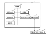
- FIG. 1 is a block diagram showing a first example of a configuration of a sensor device
- FIG. FIG. 4 is a block diagram showing a second example of the configuration of the sensor device
- 3 is a block diagram showing an example of the internal functional configuration of the learning model generation device
- FIG. 3 is a conceptual diagram showing an example of contents of measurement data
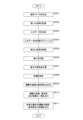
- 4 is a flow chart showing an example of a procedure of processing for generating a learning model
- FIG. 4 is a conceptual diagram showing an example of contents of motion data
- 4 is a conceptual diagram showing functions of a learning model
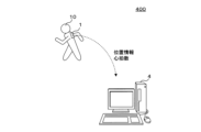
- FIG. 1 is a schematic diagram showing a configuration example of a fatigue determination system that determines fatigue of a player;
- FIG. It is a block diagram which shows the functional structural example inside a fatigue determination apparatus.
- FIG. 10 is a flowchart showing an example of a procedure for determining fatigue of a player;
- FIG. 3 is a conceptual diagram showing an example of the contents of input data;
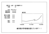
- FIG. 4 is a schematic diagram showing an example of an image displayed by the fatigue determination device;
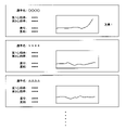
- FIG. 10 is a schematic diagram showing an example of an image displayed by the fatigue determination device for outputting a difference and a cumulative sum of the differences for a plurality of players;
- 4 is a flow chart showing an example of a procedure for determining a player's physical condition;
- FIG. 10 is a schematic diagram showing an example of an image including exercise intensity and fatigue level for a plurality of athletes;
- FIG. 10 is a schematic diagram showing an example of an image including a list of exercise intensity, fatigue level, and physical condition of a plurality of athletes;
- FIG. 10 is a schematic diagram showing an example of an image including exercise intensity, fatigue level, and physical condition of a specific player.
- FIG. 1 is a schematic diagram showing a configuration example of a learning model generation system 200 for generating a learning model.
- a learning model generation system 200 includes a sensor device 1 worn by a player 10 who plays sports, and a learning model generation device 2 that executes information processing for generating a learning model.
- the sensor device 1 is a wearable sensor worn by the player 10 .
- the sensor device 1 is part of clothing or equipment.
- the sensor device 1 may be attached to the body of the player 10 .
- the sensor device 1 is used to measure the position, heart rate, and number of steps of the player 10, and the learning model generation device 2 acquires the position information indicating the position of the player 10, the heart rate, and the number of steps, and generates a learning model. Execute information processing for generation.
- FIG. 2 is a block diagram showing a first example of the configuration of the sensor device 1.
- the sensor device 1 includes a control section 11 , a position sensor 12 , a heartbeat sensor 13 , a step counter 18 , a storage section 14 and an interface section 15 .
- the control section 11 controls each section of the sensor device 1 .
- the control unit 11 is configured using a processor.
- the control unit 11 may perform processing for measuring time.
- the storage unit 14 stores programs or data necessary for the operation of the sensor device 1 .
- the storage unit 14 is nonvolatile memory.
- the storage unit 14 stores sensor identification information unique to the sensor device 1 for identifying the sensor device 1 .
- the position sensor 12 is a sensor that measures the position of the sensor device 1 .
- the position sensor 12 measures the position using a positioning system such as GPS (Global Positioning System).
- position sensor 12 measures position by receiving signals transmitted from positioning satellites, such as GPS satellites. A part of the processing for measuring the position may be executed by the control unit 11 .
- Position sensor 12 measures the position of player 10 by measuring the position of sensor device 1 .
- the heart rate sensor 13 measures the heart rate of the player 10 for a predetermined period of time.
- heart rate sensor 13 measures the heart rate for 20 seconds.
- the heartbeat sensor 13 is an optical sensor.
- a step counter 18 measures the number of steps. The number of steps is the number of steps taken within a predetermined period of time.
- the step counter 18 has an acceleration sensor, and performs processing for specifying the number of steps according to the measurement result of the acceleration sensor.
- the sensor device 1 may have a form in which the control unit 11 performs processing for specifying the number of steps according to the measurement result of the acceleration sensor.
- a detachable portable memory 16 is attached to the interface unit 15 and data is written into the portable memory 16 .
- the control unit 11 stores data including position information indicating the position measured by the position sensor 12, the heart rate measured by the heartbeat sensor 13, and the number of steps measured by the step counter 18 in the portable memory 16 via the interface unit 15. .
- the data including position information, heart rate, and step count includes information indicating the time when the position was measured, information indicating the time when the heart rate was measured, and information indicating the time when the step count was measured.
- sensor identification information is included in the data including position information, heart rate and step count.
- the control unit 11 stores data including position information, heart rate, and step count obtained in a plurality of periods in the portable memory 16 via the interface unit 15 .
- the portable memory 16 is detached from the interface section 15 and attached to the memory reader 31 outside the sensor device 1 .
- the memory reader 31 reads data including position information, heart rate and step count stored in the portable memory 16 .
- the sensor device 1 may have a form in which the interface section 15 is directly attached to the memory reader 31 without using the portable memory 16 .
- the control unit 11 stores the position information, the heart rate and the number of steps in the storage unit 14, and the memory reader 31 reads the data including the position information, the heart rate and the number of steps through the interface unit 15.
- FIG. 3 is a block diagram showing a second example of the configuration of the sensor device 1.
- the sensor device 1 includes a control section 11 , a position sensor 12 , a heartbeat sensor 13 , a storage section 14 and a transmission section 17 .
- the control unit 11, storage unit 14, position sensor 12, and heart rate sensor 13 are the same as in the first example.
- the transmission unit 17 uses wired communication or wireless communication to transmit data to the receiving device 32 outside the sensor device 1 .
- the control unit 11 transmits data including position information, heart rate, and step count obtained in a plurality of periods from the transmission unit 17 to the reception device 32 .
- the sensor device 1 may include both the interface section 15 and the transmission section 17 .
- the learning model generation system 200 may be configured to measure the position of the sensor device 1 by a method other than using a positioning system. For example, the sensor device 1 transmits a signal to the outside, a receiving device outside the sensor device 1 receives the signal from the sensor device 1, and the position of the sensor device 1 is measured based on the signal received by the receiving device.
- FIG. 4 is a block diagram showing an example of the internal functional configuration of the learning model generation device 2.
- the learning model generation device 2 executes a learning model generation method.
- the learning model generation device 2 is a computer such as a server device or a personal computer.
- the learning model generation device 2 includes a calculation unit 21 , a memory 22 , a drive unit 23 , a storage unit 24 , an operation unit 25 , a display unit 26 and an interface unit 27 .
- the calculation unit 21 is configured using, for example, a CPU (Central Processing Unit), a GPU (Graphics Processing Unit), or a multi-core CPU.
- the calculation unit 21 may be configured using a quantum computer.
- the memory 22 stores temporary data generated along with computation.
- the memory 22 is, for example, a RAM (Random Access Memory).
- a drive unit 23 reads information from a recording medium 20 such as an optical disc or a portable memory.
- the storage unit 24 is nonvolatile, such as a hard disk or nonvolatile semiconductor memory.
- the calculation unit 21 causes the drive unit 23 to read the computer program 241 recorded on the recording medium 20 and causes the storage unit 24 to store the read computer program 241 .
- the calculation unit 21 executes processing necessary for the learning model generation device 2 according to the computer program 241 .
- Computer program 241 may be a computer program product.
- the computer program 241 may be downloaded from outside the learning model generation device 2 .
- the computer program 241 may be pre-stored in the learning model generation device 2 . In these cases, the learning model generation device 2 does not have to include the drive section 23 .
- the operation unit 25 accepts input of information such as text by accepting operations from the user.
- the operation unit 25 is, for example, a touch panel, pen tablet, keyboard, or pointing device.
- the display unit 26 displays images.
- the display unit 26 is, for example, a liquid crystal display or an EL display (Electroluminescent Display).
- the operation section 25 and the display section 26 may be integrated.
- the interface unit 27 is connected to a memory reader 31 or a receiving device 32 (not shown in FIG. 4).
- the memory reader 31 inputs the data including the position information, the heart rate and the number of steps read from the portable memory 16 to the learning model generation device 2 through the interface section 27 .
- the receiving device 32 inputs the received data including the position information, the heart rate and the number of steps to the learning model generating device 2 through the interface section 27 .
- the interface unit 27 may be equipped with the portable memory 16 and may read data from the portable memory 16 or may receive data transmitted from the sensor device 1 .
- the learning model generation device 2 transmits, through the interface unit 27, the position information indicating the position of the player 10 measured by the sensor device 1, the heart rate of the player 10 measured by the sensor device 1, and the heart rate of the player 10 measured by the sensor device 1. Obtain data including the number of steps of the player 10 who has completed the step.
- the learning model generation device 2 may be configured by a plurality of computers, data may be distributed and stored by the plurality of computers, and processing may be executed by the plurality of computers in a distributed manner.
- the learning model generation device 2 may be realized using cloud computing, or may be realized by a plurality of virtual machines provided within one computer.
- the storage unit 24 stores player data in which personal information of a plurality of players 10 is recorded.
- the player data includes sensor identification information of the sensor device 1 worn by the player 10, the birthday of the player 10, and the position of the player 10 in the sport.
- the learning model generation system 200 includes multiple sensor devices 1 worn by multiple players 10 .
- the learning model generation device 2 acquires data including position information, heart rate and step count from each of the plurality of sensor devices 1 . That is, the learning model generation device 2 generates position information indicating the position of the player 10 measured by the plurality of sensor devices 1, the heart rate of the player 10 measured by the plurality of sensor devices 1, and the player measured by the plurality of sensor devices 1. Get a step number of 10.
- the learning model generation device 2 stores the measurement data 242 including the position information, heart rate, and number of steps of the players 10 in the storage unit 24 . For example, when a sports practice is performed, the sensor device 1 is used to acquire the position information, heart rate and step number of each player 10, and measurement data including the acquired position information, heart rate and step number are obtained. 242 are stored.
- FIG. 5 is a conceptual diagram showing an example of the contents of the measurement data 242.
- the measurement data 242 includes location information, heart rate, and number of steps for each player 10 .
- the measurement data 242 includes player identification information for identifying the player 10 and position information indicating the position of the player 10 in the sport.
- the player identification information is information unique to the player 10 .
- Player identification information corresponds to personal identification information.
- the player identification information may be the same as the sensor identification information. Alternatively, the player identification information is recorded in the player data in association with the sensor identification information.
- the learning model generation device 2 refers to the player data, identifies the player identification information corresponding to the sensor identification information included in the data acquired from the sensor device 1 , and records it in the measurement data 242 .
- the position information is information that differs depending on the position of the player 10.
- the sport is soccer
- the position information differs depending on whether the player 10 is a forward or a goalkeeper.
- the learning model generation device 2 refers to the player data, specifies position information corresponding to the player identification information, and records it in the measurement data 242 .
- the measurement data 242 may not include player identification information or position information.
- the position information indicating the position of the player 10, the heart rate of the player 10, and the number of steps of the player 10 are recorded in association with the player identification information and position information of the player 10.
- the location information is associated with the time when the location was measured.
- the heart rate and step count are associated with the times when the heart rate and step count were measured.
- the time associated with the heart rate or step count is the time at which the predetermined period of time for measuring the heart rate or step count begins or ends.
- the learning model generation device 2 generates training data for generating a learning model based on the measurement data 242, and performs processing for generating a learning model learned using the training data.
- FIG. 6 is a flow chart showing an example of a procedure of processing for generating a learning model. A step is abbreviated as S below.
- the computing unit 21 of the learning model generation device 2 executes processing according to the computer program 241 .
- the learning model generation device 2 generates motion data representing the motion of each player 10 from the position information and number of steps of each player 10 included in the measurement data 242 (S11).
- FIG. 7 is a conceptual diagram showing an example of contents of motion data.
- the movement data includes the speed, acceleration, absolute value of acceleration, number of steps, metabolic power, and MSF (muscular fatigue) of the player 10 as feature quantities representing characteristics of the movement of the player 10 .
- MSF muscle fatigue
- the calculation unit 21 calculates the velocity, the acceleration, and the absolute value of the acceleration based on the change in position information and the change in time associated with the position information. Further, the calculation unit 21 causes the motion data to include the number of steps based on the number of steps included in the measurement data 242 . For example, the calculation unit 21 calculates the number of steps included in the measurement data 242 itself, or the number of steps calculated from the number of steps included in the measurement data 242 and changes the length of the counting time. , is included in the motion data as the number of steps. The calculation unit 21 calculates a value obtained by multiplying the acceleration and the velocity as the metabolic power. The calculation unit 21 calculates, as the MSF, the number of times an angle change of 100 degrees or more has progressed by 4 m, based on the change in the movement distance and the movement direction.
- the calculation unit 21 calculates the average value or maximum value of each feature amount included in the motion data within a predetermined period of time.
- the predetermined time is 20 seconds.
- the motion data includes the average value or maximum value of each feature amount in each of a plurality of periods. That is, the calculation unit 21 calculates the average or maximum value of velocity, acceleration, absolute value of acceleration, number of steps, metabolic power, and MSF in each of a plurality of periods.
- FIG. 7 shows the average value or the maximum value of each feature amount in each of the period 0 to 20 seconds before, the period 20 to 40 seconds before, and the period 40 to 60 seconds before, based on an arbitrary time. Examples included in operational data are shown.
- the motion data includes feature amounts in a plurality of periods, thereby representing temporal changes in the motion of the player 10 .
- the calculation unit 21 generates motion data for a plurality of times. Note that the learning model generation system 200 does not measure the number of steps by the sensor device 1, and the learning model generation device 2 detects the movement distance obtained from the change in the position information in S11, the change in the movement direction, the change in the speed, or the change in the acceleration. It may be in the form of calculating the number of steps based on.
- the learning model generation device 2 calculates the heart rate (heart rate data) of each player 10 from the heart rate of each player 10 included in the measurement data 242 (S12).
- Heart rate is the heart rate divided by the maximum heart rate.
- Maximum heart rate is the highest possible heart rate for a person. Maximum heart rate depends on the age of the person.
- a heart rate is a value obtained by correcting a heart rate according to a person's age, and corresponds to heart rate data. By correcting the heart rate according to the person's age, the influence of age can be eliminated in the generation of the learning model and the determination of fatigue. For example, an athlete's maximum heart rate per minute is represented by the following equation (1).
- Maximum heart rate 210 - 0.5 x age (1)
- the calculation unit 21 reads the birthday of the player 10 from the player data based on the player identification information, calculates the age, and calculates the maximum heart rate using equation (1).
- the calculation unit 21 also calculates the heart rate by dividing the heart rate included in the measurement data 242 by the maximum heart rate. For example, if the measurement data 242 includes the heart rate for 20 seconds, the calculation unit 21 converts the maximum heart rate for 1 minute calculated using equation (1) into the maximum heart rate for 20 seconds. , to calculate the heart rate.
- the calculation unit 21 may calculate the heart rate by converting the heart rate included in the measurement data 242 into heart rate per minute and dividing the heart rate by the maximum heart rate per minute. Note that the maximum heart rate may be specified by a method other than the method using equation (1).
- maximum heart rate can be calculated using formulas other than formula (1).
- a table recording the correspondence between age and maximum heart rate may be stored in the storage unit 24 in advance, and the maximum heart rate corresponding to age may be specified based on the table.
- the calculator 21 calculates heart rate at a plurality of times. The processes of S11 and S12 may be performed in reverse order.
- the learning model generation device 2 then generates training data including motion data and heart rate (S13).
- the calculation unit 21 generates training data by associating motion data and heart rate that are related to the same time. For example, if the reference time for calculating the motion data and the time associated with the heart rate on which the heart rate is based match within a predetermined Generate a dataset that correlates heart rate.
- the computing unit 21 generates a plurality of data sets and generates training data including the plurality of data sets.
- the training data further includes a preliminary heart rate, which is the heart rate at a time before the heart rate on which the heart rate was based was obtained.
- Preliminary heart rate corresponds to preliminarily heart rate data.
- the preliminary heart rate the heart rate at the point in time retroactively for a predetermined retroactive time is used. For example, the heart rate obtained from the heart rate 60 to 80 seconds before is used as the preliminary heart rate.
- the calculation unit 21 selects a preliminary heart rate from the calculated heart rate and associates it with the motion data and the heart rate.
- the training data further includes player identification information and position information.
- the calculation unit 21 associates the player identification information and position information with the motion data and heart rate.
- the training data includes a plurality of data sets that include motion data, heart rate, preliminary heart rate, player identification information, and position information in association therewith.
- the learning model generation device 2 acquires the training data 243 by executing the processes of S11 to S13.
- the calculation unit 21 stores the generated training data 243 in the storage unit 24 .
- the learning model generation device 2 executes the processes of S11 to S13 for the plurality of players 10.
- FIG. One or more data sets are generated for each player 10
- training data 243 includes multiple data sets for multiple players 10 .
- the processing of S11 to S13 may be executed each time the position information, heart rate and number of steps are obtained from the sensor device 1, or may be executed at the stage when a certain amount of information is recorded in the measurement data 242. Note that the processing of S11 to S13 may be performed outside the learning model generation device 2, and the generated training data 243 may be input to the learning model generation device 2 from the outside.
- the learning model generation device 2 next uses the training data 243 to generate a learning model used to predict the heart rate (S14).
- the learning model is realized by executing information processing by the calculation unit 21 according to the computer program 241 .
- the storage unit 24 stores data necessary for realizing the learning model.
- the learning model may be configured by hardware.
- a learning model may be implemented using a quantum computer.
- FIG. 8 is a conceptual diagram showing the functions of the learning model.
- the learning model is input with motion data, preliminary heart rate, player identification information and position information.
- the learning model is trained to output a heart rate when motion data, a prior heart rate, player identification information, and position information are input.
- the learning model is constructed using LightGBM (Light Gradient Boosting Machine).
- the learning model may be constructed using neural networks, transformers, or LSTMs (Long Short-Term Memory).
- the calculation unit 21 inputs the motion data, pre-heartbeat rate, player identification information, and position information included in the training data 243 to the learning model, and performs learning of the learning model.
- the learning model outputs a heart rate in response to inputs of motion data, a prior heart rate, player identification information, and position information.
- the calculation unit 21 acquires the heart rate output by the learning model, and outputs the heart rate and the learning model associated with the motion data, the preliminary heart rate, the player identification information, and the position information input to the learning model in the training data 243.
- the parameters of the learning model calculation are adjusted so that the error with the calculated heart rate becomes small.
- the parameters are adjusted to output a heart rate that is approximately the same as the heart rate associated with the motion data, heart rate, preliminary heart rate, player identification information, and position information.
- the calculation unit 21 repeats the process using a plurality of data sets included in the training data 243 and adjusts the parameters of the learning model, thereby performing machine learning of the learning model.
- the computing unit 21 adjusts the parameters of the learning model using Optuna (registered trademark).
- the calculation unit 21 divides the training data 243 into a plurality of pieces, generates a plurality of learning models by cross-validation, and averages and fuses the plurality of learning models to generate a single learning model.
- the computing unit 21 may adjust the parameters of the learning model using other algorithms.
- the calculation unit 21 stores the learned data recording the adjusted final parameters in the storage unit 24 . Thus, a trained learning model is generated.
- the learning model generation device 2 ends the processing for generating the learning model.
- the higher the intensity of a person's exercise the higher the heart rate. Therefore, there is a relationship between the motion of the player 10 and the heart rate, and it is possible to generate a learning model that generates the heart rate of the player 10 from motion data representing the motion of the player 10 . Also, when fatigue is high, a person's heart rate increases.
- the heart rate obtained from the motion data using the learning model is the heart rate of the player 10 under normal conditions. When the actual heart rate is higher than the heart rate obtained from the motion data using the learning model, it can be determined that the player 10 is more tired than usual. Thus, the heart rate obtained from motion data using the learning model can be used as a basis for determining fatigue of the player 10 .
- the heart rate is affected by the previous heart rate. For example, even if the intensity of exercise is the same, the higher the heart rate immediately before, the higher the heart rate.
- the learning model can output a more accurate heart rate.
- the learning model can output a more accurate heart rate according to the individuality of the player 10 . If the position of the player 10 is different, the content of the exercise performed by the player 10 will be different, and a difference may occur in the relationship between the motion data and the heart rate.
- the learning model can output a more accurate heart rate according to the player's 10 position.
- the learning model may be in a form in which any one of the preliminary heart rate, player identification information, and position information is not input.
- FIG. 9 is a schematic diagram showing a configuration example of a fatigue determination system 400 that determines fatigue of the player 10.
- the fatigue determination system 400 executes a fatigue determination method.
- a fatigue determination system 400 includes a sensor device 1 worn by a player 10 who plays sports, and a fatigue determination device 4 that executes information processing for determining fatigue.
- the sensor device 1 is the same as the sensor device 1 used in the learning model generation system 200 .
- the sensor device 1 measures the position, heart rate and number of steps of the player 10 .
- the fatigue determination device 4 acquires the position information indicating the position of the player 10 , the heart rate and the number of steps from the sensor device 1 .
- FIG. 10 is a block diagram showing an example of the internal functional configuration of the fatigue determination device 4.
- the fatigue determination device 4 is a computer such as a personal computer, a tablet computer, or a smart phone.
- the fatigue determination device 4 includes an arithmetic unit 41 , a memory 42 , a drive unit 43 , a storage unit 44 , an operation unit 45 , a display unit 46 and an interface unit 47 .
- the computing unit 41 is configured using, for example, a CPU, GPU, or multi-core CPU.
- the computing unit 41 may be configured using a quantum computer.
- the memory 42 stores temporary data generated along with computation.
- the memory 42 is, for example, RAM.
- a drive unit 43 reads information from a recording medium 40 such as an optical disc or a portable memory.
- the storage unit 44 is nonvolatile, such as a hard disk or nonvolatile semiconductor memory.
- the calculation unit 41 causes the drive unit 43 to read the computer program 441 recorded on the recording medium 40 and causes the storage unit 44 to store the read computer program 441 .
- the calculation unit 41 executes processes necessary for the fatigue determination device 4 according to the computer program 441 .
- Computer program 441 may be a computer program product.
- the computer program 441 may be downloaded from outside the fatigue determination device 4 .
- the computer program 441 may be stored in the fatigue determination device 4 in advance. In these cases, the fatigue determination device 4 does not have to include the drive section 43 .
- the operation unit 45 accepts input of information such as text by accepting operations from the user.
- the operation unit 45 is, for example, a touch panel, pen tablet, keyboard, or pointing device.
- the display unit 46 displays images.
- the display unit 46 is, for example, a liquid crystal display or an EL display.
- the operation section 45 and the display section 46 may be integrated.
- the interface unit 47 is connected to the memory reader 31 or the receiving device 32 (not shown in FIG. 10).
- the memory reader 31 or the receiving device 32 inputs data including position information, heart rate and step count to the fatigue determination device 4 through the interface section 47 .
- the interface unit 47 may be equipped with the portable memory 16 and read data from the portable memory 16 or may receive data transmitted from the sensor device 1 .
- the fatigue determination device 4 transmits the position information indicating the position of the player 10 measured by the sensor device 1, the heart rate of the player 10 measured by the sensor device 1, and the heart rate measured by the sensor device 1 through the interface unit 47.
- the fatigue determination device 4 may be composed of a plurality of computers.
- the fatigue determination device 4 may be realized using cloud computing, or may be realized by a plurality of virtual machines provided within one computer.
- the fatigue determination device 4 is equipped with a learning model 442.
- the learning model 442 is implemented by the computing unit 41 executing information processing according to the computer program 441 .
- the learning model 442 is a learning model learned by the learning model generation device 2 .
- the fatigue determination device 4 is provided with a learning model 442 by storing in the storage unit 44 learned data recording parameters of the learning model learned by the learning model generation device 2 .
- the learned data is read from the recording medium 40 by the drive unit 43 or downloaded.
- the learning model 442 may be configured by hardware.
- Learning model 442 may be implemented using a quantum computer.
- the learning model 442 may be provided outside the fatigue determination device 4 , and the fatigue determination device 4 may execute processing using the external learning model 442 .
- learning model 442 may be configured in the cloud.
- the storage unit 44 stores player data.
- the fatigue determination device 4 acquires data including position information, heart rate and number of steps from the sensor device 1 . That is, the fatigue determination device 4 acquires position information indicating the position of the player 10 measured by the sensor device 1 , the heart rate of the player 10 , and the number of steps of the player 10 .
- the fatigue determination device 4 stores measurement data including position information, heart rate and number of steps in the storage unit 24 . For example, when a sports match is held, the sensor device 1 is used to acquire the position information, heart rate, and step count of the player 10, and measurement data including the acquired position information, heart rate, and step count is generated. remembered.
- the fatigue determination device 4 generates input data to be input to the learning model, and uses the learning model 442 to determine the fatigue of the player 10 .
- FIG. 11 is a flow chart showing an example of a procedure for determining fatigue of the player 10 .
- the calculation unit 41 of the fatigue determination device 4 executes processing according to the computer program 441 .
- the fatigue determination device 4 generates motion data representing the motion of the player 10 from the position information of the player 10 and the number of steps included in the measurement data (S201).
- the calculation unit 41 calculates motion data by calculating velocity, acceleration, absolute value of acceleration, metabolic power, and MSF based on changes in position information and changes in time associated with the position information. Generate. Further, the calculation unit 41 causes the motion data to include the number of steps based on the number of steps included in the measurement data.
- the motion data includes the average or maximum values of velocity, acceleration, absolute value of acceleration, number of steps, metabolic power and MSF in each of a plurality of periods, as shown in FIG.
- the fatigue determination device 4 acquires motion data.
- the sensor device 1 does not measure the number of steps, and the fatigue determination device 4 is based on the movement distance, the change in the movement direction, the change in the speed, or the change in the acceleration obtained from the change in the position information in S201. may be configured to calculate the number of steps.
- Motion data may not include any of velocity, acceleration, absolute value of acceleration, number of steps, metabolic power, and MSF.
- the fatigue determination device 4 next calculates the first heart rate by calculating the heart rate of the player 10 from the heart rate of the player 10 included in the measurement data (S202).
- the first heart rate is the actual heart rate calculated from the heart rate of the player 10 and corresponds to the first heart rate data.
- the calculation unit 41 calculates the age of the player 10 based on the player data, calculates the maximum heart rate, and calculates the first heart rate.
- the calculator 41 calculates the first heart rate for a plurality of times.
- the processes of S201 and S202 may be performed in reverse order.
- the fatigue determination device 4 next generates input data for input to the learning model 442 (S203).
- FIG. 12 is a conceptual diagram showing an example of the contents of input data.
- the input data includes motion data, pre-heart rate, player identification information and position information.
- the calculation unit 41 specifies the first heart rate at the point in time retroactively for a predetermined retroactive time from the reference time for calculating the motion data as the preliminary heart rate.
- the calculation unit 41 generates input data by associating the motion data, the preliminary heart rate, the player identification information, and the position information, and stores the input data in the storage unit 44 .
- the calculation unit 41 associates the input data and the first heart rate related to the same time. For example, if the time that is the reference for calculating the motion data and the time associated with the heart rate on which the first heart rate is based match within a predetermined error, the calculation unit 41 performs the motion. Associate the data and the first heart rate.
- the processing of S201 to S203 may be executed each time the position information, heart rate and number of steps are obtained from the sensor device 1, or may be executed at the stage when a certain amount of information is recorded in the measurement data.
- the processing of S201 to S203 may be performed outside the fatigue determination device 4, and the generated input data and the first heart rate may be input to the fatigue determination device 4 from the outside.
- the fatigue determination device 4 inputs the input data to the learning model 442 (S204).
- the calculation unit 41 inputs the input data to the learning model 442 and causes the learning model 442 to execute processing.
- Learning model 442 outputs the second heart rate in response to the input of the input data.
- the second heart rate is a value estimated by using the learning model 442 for the heart rate of the player 10, and corresponds to the second heart rate data.
- the fatigue determination device 4 acquires the second heart rate output by the learning model 442 (S205).
- the fatigue determination device 4 next calculates the difference obtained by subtracting the second heart rate from the first heart rate (S206).
- the calculation unit 41 subtracts the second heart rate obtained by inputting the input data to the learning model 442 from the first heart rate associated with the input data.
- the calculated difference is the difference between the actual heart rate of the player 10 and the estimated heart rate of the player 10 using the learning model 442 .
- the difference is a positive value, and the heart rate of player 10 is higher than usual. Since the heart rate is higher than usual, the body of the player 10 is under a larger burden than usual, and the player 10 may be tired. It can be inferred that the greater the difference, the greater the burden on the body of the player 10 and the greater the degree of fatigue representing the intensity of fatigue.
- the fatigue determination device 4 calculates the cumulative sum of differences (S207). For example, the fatigue determination device 4 repeats the processes of S201 to S206 a plurality of times, and performs the process of S207 each time a difference is obtained. For example, the fatigue determination device 4 performs the processes of S201 to S206 based on the measurement data for a certain length of time to calculate a plurality of time-series differences, and performs the process of S207.
- the calculation unit 41 calculates a cumulative sum of differences by sequentially adding a plurality of differences. When calculating the cumulative sum, the computing unit 41 simply adds up even if the difference is a negative value.
- the cumulative sum of differences is a value calculated based on information continuously obtained from the player 10, it reflects the state of the player 10. If the cumulative sum of the differences is a positive value, it means that the heart rate of the player 10 continues to be higher than usual, and the state that the body of the player 10 is under a greater burden than usual continues. indicates that Therefore, when the cumulative sum of differences is a positive value, it is clear that the player 10 is tired. The greater the cumulative sum of differences, the greater the degree of fatigue of the player 10 .
- the fatigue determination device 4 next outputs the difference and the cumulative sum of the differences (S208).
- S ⁇ b>208 the calculation unit 41 generates an image including the difference and the cumulative sum of the differences, and displays it on the display unit 46 .
- the greater the difference and the cumulative sum of the differences the greater the fatigue level of the player 10. Therefore, the difference and the cumulative sum of the differences can be used as information representing the fatigue level.
- the difference output in S208 and the cumulative sum of the differences represent the degree of fatigue of the player 10 . In the image containing the difference and the cumulative sum of the differences, if the difference and the cumulative sum of the differences are output, it is not necessary to explicitly output that the information is the degree of fatigue or fatigue.
- the calculation unit 41 stores the history of differences and the history of cumulative sums of differences in the storage unit 44 .
- the fatigue determination device 4 may output only one of the difference and the cumulative sum of the differences.
- the fatigue determination device 4 determines whether or not the calculated difference or cumulative sum of differences is equal to or greater than a predetermined threshold (S209).
- the calculation unit 41 compares the difference or the accumulated sum of the differences with a predetermined threshold to make a determination.
- the threshold is stored in advance in the storage unit 44 or included in the computer program 441 .
- the difference threshold is different from the cumulative difference threshold.
- the fatigue determination device 4 terminates the process of determining fatigue of the player 10. If the difference or cumulative sum of differences is equal to or greater than the threshold (S209: YES), the fatigue determination device 4 outputs a warning indicating that the player 10 is tired (S210). In S ⁇ b>210 , the calculation unit 41 generates an image including a warning in addition to the difference and the cumulative sum of the differences, and displays it on the display unit 46 . In S209 and S210, the fatigue determination device 4 ends the process when the difference or the cumulative sum of the differences is less than the threshold, and outputs a warning when the difference or the cumulative sum of the differences exceeds the threshold. good.
- the output warning is a notification according to the difference or cumulative sum of the differences.
- the fatigue determination device 4 ends the process of determining fatigue of the player 10.
- FIG. The fatigue determination device 4 repeats the processing of S201 to S210 to update the image displayed on the display unit .
- FIG. 13 is a schematic diagram showing an example of an image displayed by the fatigue determination device 4.
- the image includes the player's 10 name and age.
- the calculation unit 41 generates an image including the name and age of the player 10 based on the personal information recorded in the player data.
- the image includes the date and time, the current time, and the time when the fatigue determination was started.
- the image also shows the maximum heart rate of the player 10, the first heart rate which is the actual heart rate, the second heart rate estimated by the learning model 442, and the second heart rate subtracted from the first heart rate.
- the resulting difference and the cumulative sum of the differences are displayed. In this way, information about the fatigue of the player 10 is output.
- the user can know the current state of the player 10 by checking the first heart rate of the player 10 . Further, the user can know the fatigue level of the player 10 by checking the difference representing the fatigue level and the cumulative sum of the differences.
- the image includes a graph showing changes in fatigue level over time.
- the calculation unit 41 uses the cumulative sum of differences as information representing the fatigue level, generates a graph showing the time change of the calculated cumulative sum of differences as the time change of the fatigue level, and displays an image including the generated graph on the display unit. 46.
- the user can know how tired the player 10 is and how fatigue is accumulated by confirming the change in the degree of fatigue over time. For example, the fatigue of the player 10 is suppressed by adjusting the exercise of the player 10 according to the time change of the fatigue level.
- FIG. 13 shows an example of outputting a warning indicating that the player 10 is tired.
- text warns that the degree of fatigue exceeds the allowable value.
- the user can know that the fatigue level of the player 10 is dangerously high. For example, by causing the player 10 to stop exercising when the warning is output, the occurrence of injury is suppressed.
- the processing of S201-S210 can be executed for multiple players 10.
- the fatigue determination device 4 executes S201 to S210 regarding the plurality of players 10 in order or in parallel, and outputs the differences regarding the plurality of players 10 and the cumulative sum of the differences.
- the fatigue determination device 4 stores, in the storage unit 44, the history of differences and the history of cumulative sums of differences for each of the plurality of players 10 .
- the fatigue determination device 4 may output the difference and the cumulative sum of the differences for the plurality of players 10.
- the calculation unit 41 generates an image including the difference and the cumulative sum of the differences regarding the plurality of players 10 and displays it on the display unit 46 .
- FIG. 14 is a schematic diagram showing an example of an image displayed by the fatigue determination device 4 in order to output the differences and cumulative sums of the differences regarding the plurality of players 10.
- the image includes information about each of the multiple players 10 .
- the image includes the name of each player 10, the first heart rate, the second heart rate, the difference obtained by subtracting the second heart rate from the first heart rate, and the cumulative sum of the differences.
- Also included is a graph showing fatigue over time for each player 10 . For example, the time change of the cumulative sum of the differences is used as the time change of the fatigue level. In this way, information about the fatigue of multiple players 10 is output.
- the user can check the information on fatigue of multiple players 10 and know the current conditions of multiple players 10 . Also, the user can know the fatigue levels of the plurality of players 10 .
- FIG. 14 shows an example in which a warning indicating that one player 10 is tired is output by text "Caution!. By confirming the warning, the user can know that there is a player 10 whose degree of fatigue is dangerously high.
- the fatigue determination device 4 includes information related to the one player 10 as shown in FIG. Images may be displayed.
- the fatigue determination system 400 may include a plurality of fatigue determination devices 4. Each of the plurality of fatigue determination devices 4 may individually execute S201 to S210 regarding any player 10. FIG.
- the sensor device 1 attached to the player 10 is used to measure the position, heart rate, and number of steps of the player 10, acquire movement data and heart rate of the player 10, and obtain movement data.
- a learning model is generated by learning using training data including heart rate and heart rate. The learning model outputs the heart rate when motion data is input. By using a learning model, the heart rate can be inferred from the motion data. Since a person's heart rate changes according to fatigue, the heart rate estimated using the learning model can serve as a basis for determining the fatigue of the player 10 .
- the first heart rate which is the actual heart rate
- the second heart rate which is the heart rate estimated using the learning model
- the body of the player 10 is under a greater burden than usual.
- the degree of fatigue of the player 10 can be visualized. By taking care of the player 10 according to the visualized degree of fatigue, such as stopping the player 10 who is tired from exercising, it is possible to suppress the occurrence of injuries.
- the fatigue determination device 4 outputs a warning according to the degree of fatigue, but the fatigue determination device 4 may be configured to output information other than the warning according to the degree of fatigue.
- the fatigue determination device 4 outputs a warning not based on the degree of fatigue, but in accordance with the transition of the difference obtained by subtracting the second heart rate from the first heart rate, the cumulative sum of the differences, or the transition of the degree of fatigue.
- the form of notifying the timing of a break or the timing of a player change may be used. That is, the fatigue determination device 4 may output a notification corresponding to the difference or the accumulated sum of the differences, including notification corresponding to the transition of fatigue or the degree of fatigue.
- the second heart rate is obtained as a value according to motion data representing the motion of the player 10 by using the learning model 442 . Therefore, the second heart rate can be used as an index representing the intensity of exercise performed by the player 10 .
- the second heart rate is represented by a numerical value in the range of 0-1.0 (0%-100%). Since the learning model 442 is trained using training data including motion data and heart rate obtained in a predetermined period such as one month in the past, the intensity of exercise indicated by the second heart rate is similar to that of the player 10 in the past. indicates how much percentage of the intensity of the exercise performed by Exercise intensity includes both quantitative and qualitative intensity.
- Embodiment 2 shows a form that clarifies the relationship between the exercise intensity, the degree of fatigue, and the physical condition of the player 10 using the second heart rate as an index.
- the configuration of the fatigue determination system 400 is the same as that of the first embodiment.
- the fatigue determination device 4 performs processing for managing the physical condition of the player 10 .
- FIG. 15 is a flowchart showing an example of a procedure for determining the physical condition of the player 10. As shown in FIG.
- the fatigue determination device 4 executes the processes of S301 to S307 similar to S201 to S207.
- the fatigue determination device 4 next identifies the physical condition of the player 10 (S308).
- the fatigue determination device 4 uses the difference obtained by subtracting the second heart rate from the first heart rate or the cumulative sum of the differences as information representing the degree of fatigue. For example, the cumulative sum of differences is used as the fatigue level value.
- the fatigue level value As the degree of fatigue increases, the value of the degree of fatigue increases. When the fatigue level value is positive, the fatigue level is large, and when the fatigue level value is negative, the fatigue level is small.
- the fatigue determination device 4 uses the second heart rate as an index representing the intensity of exercise performed by the player 10 . Specifically, the value of the intensity of the exercise performed by the player 10 is the value of the second heart rate, and can take values in the range of 0% to 100%.
- the fatigue determination device 4 identifies the physical condition of the player 10 by comparing the intensity of the exercise performed by the player 10 and the degree of fatigue of the player 10 .
- the higher the intensity of exercise the greater the degree of fatigue tends to be. If the degree of fatigue is small even though the intensity of the exercise is high, it is recognized that the physical condition of the player 10 is good. If the degree of fatigue is high even though the intensity of the exercise is low, it is recognized that the physical condition of the player 10 is poor.
- the physical condition of the player 10 is normal when the exercise intensity is high and the fatigue level is high, and when the exercise intensity is low and the fatigue level is low. Thus, the physical condition of the player 10 can be identified by comparing the exercise intensity and the degree of fatigue.
- the calculation unit 41 identifies the physical condition of the player 10 based on the exercise intensity and fatigue level.
- the calculation unit 41 expresses the physical condition of the player 10 numerically.
- the calculation unit 41 increases the numerical value of the physical condition (good physical condition) as the intensity of the exercise is high and the degree of fatigue is small, and decreases the numerical value of the physical condition (poor physical condition) as the intensity of the exercise is low and the degree of fatigue is large.
- calculate your physical condition For example, the calculation unit 41 calculates physical condition numerical values by performing calculations according to a predetermined algorithm included in the computer program 441 based on exercise intensity and fatigue level.
- a table in which exercise intensity and fatigue level are associated with physical condition is stored in advance in the storage unit 44, and the calculation unit 41 extracts the physical condition value associated with the exercise intensity and fatigue level from the table. By doing so, the physical condition of the player 10 is specified.
- the fatigue determination device 4 executes the processes of S301 to S308 for each of the plurality of players 10.
- the fatigue determination device 4 stores the difference obtained by subtracting the second heart rate from the first heart rate, the accumulated sum of the differences, and the physical condition of each of the plurality of athletes 10 in the storage unit 44 through the processes of S301 to S308. .
- the fatigue determination device 4 repeatedly executes the processes of S301 to S308. That is, the fatigue determination device 4 generates motion data at a plurality of points in time, and acquires the difference obtained by subtracting the second heart rate from the first heart rate at each point in time, the accumulated sum of the differences, and the physical condition.
- the fatigue determination device 4 periodically executes the processes of S301 to S308, such as once a day.
- the fatigue determination device 4 stores in the storage unit 44 the history of the difference obtained by subtracting the second heart rate from the first heart rate, the history of the cumulative sum of the differences, and the physical condition history for each of the plurality of athletes 10. do.
- the fatigue determination device 4 then outputs the intensity of the exercises performed by the multiple players 10 and the fatigue levels of the multiple players 10 (S309).
- the calculation unit 41 outputs the exercise intensity and the fatigue level by displaying an image including the exercise intensity and the fatigue level of the plurality of players 10 on the display unit 46 .
- FIG. 16 is a schematic diagram showing an example of an image including exercise intensity and fatigue level for a plurality of players 10.
- the calculation unit 41 calculates the sum of the fatigue levels of the plurality of players 10 at a specific point in time, based on the difference obtained by subtracting the second heart rate from the first heart rate or the accumulated sum of the differences, stored in the storage unit 44, and An average intensity of exercises performed by a plurality of athletes 10 is calculated.
- the image displayed on the display unit 46 includes a calendar indicating a specific point in time (date). For example, the user operates the operation unit 45 to specify a specific time using a calendar, and the calculation unit 41 calculates the total fatigue level and the average exercise intensity at the specified time. The specific point in time can also be changed by the user operating the operation unit 45 .
- the calculation unit 41 displays on the display unit 46 an image containing the calculated total fatigue level and average exercise intensity. A user viewing the image can confirm the degree of fatigue of all of the players 10 and the intensity of the exercise performed by all of the players 10 . For example, the user can manage the degree of fatigue and exercise intensity for an entire sports team to which multiple players 10 belong.
- the calculation unit 41 calculates the total fatigue level and the exercise intensity of the plurality of athletes 10 based on the history of the difference obtained by subtracting the second heart rate from the first heart rate and the history of the cumulative sum of the differences.
- the display unit 46 displays an image including a graph showing the average time change.
- the horizontal axis of the graph included in FIG. 16 indicates time, and the vertical axis indicates the total fatigue level and the average exercise intensity.
- the solid line graph shows the average exercise intensity, and the dashed line graph shows the total fatigue level.
- the user can check changes over time in the degree of fatigue of all of the players 10 and changes over time in the intensity of exercise performed by all of the players 10 . For example, the user can check how the fatigue level and exercise intensity of the entire team have changed over time.
- the calculation unit 41 displays on the display unit 46 an image including the player name and the fatigue level of the player 10 having a high fatigue level and the player 10 having a low fatigue level at a specific time.
- the user can confirm the player 10 whose degree of fatigue is particularly high and the player 10 whose degree of fatigue is particularly low.
- the user can manage the players 10 according to their fatigue levels, such as by resting the players 10 whose fatigue levels are particularly high, or encouraging the players 10 whose fatigue levels are particularly low to exercise.
- the fatigue determination device 4 outputs a list of exercise intensity, degree of fatigue, and physical condition of multiple athletes 10 at a specific time (S310).
- the calculation unit 41 displays on the display unit 46 an image containing a list of the exercise intensity, fatigue level, and physical condition of the plurality of athletes 10 at a specific point in time. output a list of A specific point in time can be specified using the calendar by the user operating the operation unit 45 .
- FIG. 17 is a schematic diagram showing an example of an image including a list of exercise intensity, fatigue level, and physical condition of a plurality of players 10.
- the physical condition is indicated by an arrow.
- An upward arrow indicates good health
- a downward arrow indicates poor health.
- the calculation unit 41 displays an image including an arrow corresponding to the physical condition value on the display unit 46 .
- the user can easily check the states of the plurality of players 10 .
- the user can manage multiple players 10 according to the exercise intensity, fatigue level, or physical condition of each player 10 .
- the players 10 who are in poor physical condition are rested and the players 10 who are in good physical condition are allowed to participate in the game, thereby managing the state of the entire team.
- the calculation unit 41 causes the display unit 46 to display an image including the average intensity of exercise performed by the plurality of athletes 10 at a specific time and the total and average fatigue levels of the plurality of athletes 10. do.
- the user can check the degree of fatigue of all of the players 10 and the intensity of the exercise performed by all of the players 10 .
- the fatigue determination device 4 outputs the exercise intensity, degree of fatigue, and physical condition of the specific player 10 (S311).
- the calculation unit 41 outputs the exercise intensity, fatigue level, and physical condition of the specific player 10 by displaying an image including the exercise intensity, fatigue level, and physical condition of the specific player 10 on the display unit 46. do. For example, when the user operates the operation unit 45, a specific player 10 is specified using an image as shown in FIG. is displayed on the display unit 46.
- FIG. 18 is a schematic diagram showing an example of an image including exercise intensity, fatigue level, and physical condition of a specific player 10.
- the image includes the player name of the particular player 10 .
- the calculation unit 41 displays on the display unit 46 an image including the degree of fatigue at a specific point in time. A specific point in time can be specified using the calendar by the user operating the operation unit 45 .
- the calculation unit 41 calculates the average fatigue level in a period of a predetermined length past the specific point in time, and displays an image including the calculated average fatigue level as the most recent fatigue level average on the display unit 46. indicate.
- the period of predetermined length is, for example, one week.
- the user can specify a specific player 10 and check the fatigue level of the specific player 10 .
- the calculation unit 41 displays on the display unit 46 an image including exercise intensity, fatigue level, and physical condition at a plurality of time points.
- the exercise intensity, fatigue level, and physical condition included in the image are associated with dates indicating respective points of time, and information indicating whether the exercise at that point in time was due to practice or a game.
- the calculation unit 41 may display an image including graphs showing changes over time in exercise intensity, fatigue level, and physical condition. A user who visually recognizes the image can confirm the intensity of exercise, degree of fatigue, and physical condition at each time point. In addition, the user can check the exercise intensity, fatigue level, and change over time of the physical condition of a specific player 10 .
- the computing unit 41 accepts an instruction to change the specific player 10 by the user operating the operation unit 45, changes the specific player 10 according to the instruction, and calculates the exercise intensity of the specific player 10 after the change,
- the degree of fatigue and physical condition may be output.
- the processes of S309, S310 and S311 may be executed in a different order, or may be repeatedly executed alternately. Alternatively, any one of S309, S310 and S311 may be omitted. After the processing of S309, S310, and S311 is completed, the fatigue determination device 4 terminates the processing for determining the physical condition of the player 10.
- the fatigue determination device 4 outputs the second heart rate as the exercise intensity. By outputting the exercise intensity, the user can confirm the intensity of the exercise performed by the player 10 .
- the fatigue determination device 4 also identifies the physical condition of the player 10 based on the degree of fatigue and the intensity of the exercise, and outputs the physical condition of the player 10 . By outputting the physical condition of the player 10, the user can check the physical condition of the player 10 and manage the player 10 according to the physical condition.
- the difference or the cumulative sum of the differences itself is used as the information representing the degree of fatigue. It may be output as information representing the degree of fatigue.
- the information representing the degree of fatigue indicates that the greater the difference or the accumulated sum of the differences, the greater the degree of fatigue.
- the difference obtained by subtracting the second heart rate from the first heart rate is used. A negative value may indicate that the greater the absolute value of the difference, the greater the degree of fatigue.
- the heart rate is used as a value obtained by correcting the heart rate according to the age of the person. may be used. For example, a value obtained by converting heart rate to heart rate at a specific age may be used.
- the form of using one learning model was shown, but the learning model generation system 200 may be in the form of generating a learning model for each player or position, and the fatigue determination device 4 The second heart rate may be acquired using a learning model for each player or position.
- the sensor device 1 measures the position information, heart rate and number of steps related to the player 10, but the sensor device 1 may measure other information.
- the sensor device 1 may have an acceleration sensor and may be configured to measure the acceleration generated in the player 10 .
- the sensor device 1 is attached to the player 10 who plays sports. It may be in the form of generating a model.
- the fatigue determination system 400 may acquire general human motion data and second heart rate, and output information regarding the degree of fatigue, exercise intensity, or physical condition.
- a learning model is generated for a person who performs rehabilitation, a person who plays a game that moves the body, a person who trains, or a person who exercises in accordance with daily life, and information about the degree of fatigue, exercise intensity, or physical condition is output. good too.
Landscapes
- Health & Medical Sciences (AREA)
- Life Sciences & Earth Sciences (AREA)
- Engineering & Computer Science (AREA)
- Physics & Mathematics (AREA)
- Medical Informatics (AREA)
- Molecular Biology (AREA)
- General Health & Medical Sciences (AREA)
- Biophysics (AREA)
- Pathology (AREA)
- Biomedical Technology (AREA)
- Heart & Thoracic Surgery (AREA)
- Veterinary Medicine (AREA)
- Public Health (AREA)
- Surgery (AREA)
- Animal Behavior & Ethology (AREA)
- Physiology (AREA)
- Software Systems (AREA)
- Cardiology (AREA)
- Theoretical Computer Science (AREA)
- Child & Adolescent Psychology (AREA)
- Educational Technology (AREA)
- Hospice & Palliative Care (AREA)
- Psychiatry (AREA)
- Psychology (AREA)
- Social Psychology (AREA)
- Dentistry (AREA)
- Oral & Maxillofacial Surgery (AREA)
- Artificial Intelligence (AREA)
- Computer Vision & Pattern Recognition (AREA)
- Data Mining & Analysis (AREA)
- Evolutionary Computation (AREA)
- Developmental Disabilities (AREA)
- Computing Systems (AREA)
- General Engineering & Computer Science (AREA)
- General Physics & Mathematics (AREA)
- Mathematical Physics (AREA)
- Signal Processing (AREA)
- Measurement Of The Respiration, Hearing Ability, Form, And Blood Characteristics Of Living Organisms (AREA)
Priority Applications (1)
| Application Number | Priority Date | Filing Date | Title |
|---|---|---|---|
| JP2023549410A JPWO2023047848A1 (https=) | 2021-09-22 | 2022-08-17 |
Applications Claiming Priority (2)
| Application Number | Priority Date | Filing Date | Title |
|---|---|---|---|
| JP2021154420 | 2021-09-22 | ||
| JP2021-154420 | 2021-09-22 |
Publications (1)
| Publication Number | Publication Date |
|---|---|
| WO2023047848A1 true WO2023047848A1 (ja) | 2023-03-30 |
Family
ID=85719434
Family Applications (1)
| Application Number | Title | Priority Date | Filing Date |
|---|---|---|---|
| PCT/JP2022/031118 Ceased WO2023047848A1 (ja) | 2021-09-22 | 2022-08-17 | 学習モデルの生成方法、コンピュータプログラム、及び疲労判定方法 |
Country Status (2)
| Country | Link |
|---|---|
| JP (1) | JPWO2023047848A1 (https=) |
| WO (1) | WO2023047848A1 (https=) |
Citations (3)
| Publication number | Priority date | Publication date | Assignee | Title |
|---|---|---|---|---|
| JP2004081723A (ja) * | 2002-08-29 | 2004-03-18 | Pioneer Electronic Corp | 疲労度判別システム、疲労度判別方法、および疲労度判別用プログラム |
| JP2018043029A (ja) * | 2017-11-17 | 2018-03-22 | 積水化学工業株式会社 | 体調判定装置 |
| JP2021122580A (ja) * | 2020-02-06 | 2021-08-30 | 国立大学法人大阪大学 | 体調評価方法、および、体調評価システム |
-
2022
- 2022-08-17 JP JP2023549410A patent/JPWO2023047848A1/ja active Pending
- 2022-08-17 WO PCT/JP2022/031118 patent/WO2023047848A1/ja not_active Ceased
Patent Citations (3)
| Publication number | Priority date | Publication date | Assignee | Title |
|---|---|---|---|---|
| JP2004081723A (ja) * | 2002-08-29 | 2004-03-18 | Pioneer Electronic Corp | 疲労度判別システム、疲労度判別方法、および疲労度判別用プログラム |
| JP2018043029A (ja) * | 2017-11-17 | 2018-03-22 | 積水化学工業株式会社 | 体調判定装置 |
| JP2021122580A (ja) * | 2020-02-06 | 2021-08-30 | 国立大学法人大阪大学 | 体調評価方法、および、体調評価システム |
Non-Patent Citations (1)
| Title |
|---|
| MAENAKA, SHOGO, SUGITA, ISAMU, SUWA, HIROHIKO, ARAKAWA, YUTAKA, YASUMOTO, KEIICHI: "Walking support system based on heart rate forcast", IEICE TECHNICAL REPORT, MICT, IEICE, JP, vol. 114, no. 419 (MICT2014-68), 31 December 2014 (2014-12-31), JP, pages 61 - 66, XP009544967 * |
Also Published As
| Publication number | Publication date |
|---|---|
| JPWO2023047848A1 (https=) | 2023-03-30 |
Similar Documents
| Publication | Publication Date | Title |
|---|---|---|
| US20210090709A1 (en) | Automated health data acquisition, processing and communication system | |
| JP4636206B2 (ja) | 活動量計測システム | |
| RU2607953C2 (ru) | Захват оптических данных об упражнениях в дополнение к расчету оценки здоровья | |
| JP6539273B2 (ja) | 活動リマインダによる活動認識 | |
| US5478295A (en) | Apparatus and method of interfacing an exercise machine to a computer | |
| US20160045170A1 (en) | Information processing device, image output method, and program | |
| US20140135592A1 (en) | Health band | |
| US10007709B2 (en) | Information processing device and information processing method | |
| US10452814B2 (en) | Advice generation system, advice generation method, and advice generation device | |
| US20220008787A1 (en) | Evaluation device, evaluation system, and storing medium | |
| JPWO2017208650A1 (ja) | 発汗状態推定装置、発汗状態推定方法、および発汗状態推定プログラム | |
| JP2008246163A (ja) | 活動量計 | |
| WO2023047848A1 (ja) | 学習モデルの生成方法、コンピュータプログラム、及び疲労判定方法 | |
| US20230101907A1 (en) | Stress release degree calculation apparatus, stress release degree calculationmethod, and computer readable recording medium | |
| US20230144812A1 (en) | Stress tolerable amount calculation apparatus, stress tolerable amount calculation method, and computer readable recording medium | |
| JP7755845B2 (ja) | 体水分量測定器およびシステム | |
| JP7536962B2 (ja) | 活動量可視化によるリハビリテーション指導支援システム | |
| US20240374164A1 (en) | Functional threshold power prediction using machine learning | |
| JP2024117961A (ja) | リハビリ支援装置 | |
| JP2025132700A (ja) | プログラム、方法、及びシステム | |
| WO2017093729A1 (en) | A method and system for converting physical activity to a virtual currency | |
| JP6861033B2 (ja) | ユーザ端末、サーバ、改善提案作成装置の作動方法および状態データ生成方法 | |
| JP2016126535A (ja) | 携帯型端末及びそれを用いた活動量管理システム | |
| CN118159187A (zh) | 程序、信息处理装置以及信息处理方法 | |
| JP2018180664A (ja) | 非歩行時間測定機能付き歩数計 |
Legal Events
| Date | Code | Title | Description |
|---|---|---|---|
| 121 | Ep: the epo has been informed by wipo that ep was designated in this application |
Ref document number: 22872604 Country of ref document: EP Kind code of ref document: A1 |
|
| WWE | Wipo information: entry into national phase |
Ref document number: 2023549410 Country of ref document: JP |
|
| NENP | Non-entry into the national phase |
Ref country code: DE |
|
| 122 | Ep: pct application non-entry in european phase |
Ref document number: 22872604 Country of ref document: EP Kind code of ref document: A1 |