WO2023047553A1 - Terminal and communication method - Google Patents
Terminal and communication method Download PDFInfo
- Publication number
- WO2023047553A1 WO2023047553A1 PCT/JP2021/035197 JP2021035197W WO2023047553A1 WO 2023047553 A1 WO2023047553 A1 WO 2023047553A1 JP 2021035197 W JP2021035197 W JP 2021035197W WO 2023047553 A1 WO2023047553 A1 WO 2023047553A1
- Authority
- WO
- WIPO (PCT)
- Prior art keywords
- cell
- slot
- harq
- ack
- pucch
- Prior art date
Links
- 238000000034 method Methods 0.000 title claims description 26
- 238000004891 communication Methods 0.000 title description 69
- 230000004044 response Effects 0.000 claims abstract description 42
- 230000005540 biological transmission Effects 0.000 claims abstract description 26
- 238000010586 diagram Methods 0.000 description 30
- 230000006870 function Effects 0.000 description 15
- 230000011664 signaling Effects 0.000 description 12
- 238000012545 processing Methods 0.000 description 10
- 238000005516 engineering process Methods 0.000 description 9
- 230000001960 triggered effect Effects 0.000 description 7
- 238000001514 detection method Methods 0.000 description 6
- 230000001133 acceleration Effects 0.000 description 5
- 230000002776 aggregation Effects 0.000 description 4
- 238000004220 aggregation Methods 0.000 description 4
- 238000010295 mobile communication Methods 0.000 description 4
- 238000012986 modification Methods 0.000 description 4
- 230000004048 modification Effects 0.000 description 4
- 238000013473 artificial intelligence Methods 0.000 description 3
- 238000013507 mapping Methods 0.000 description 3
- 230000008569 process Effects 0.000 description 3
- 230000009471 action Effects 0.000 description 2
- 230000008878 coupling Effects 0.000 description 2
- 238000010168 coupling process Methods 0.000 description 2
- 238000005859 coupling reaction Methods 0.000 description 2
- 125000004122 cyclic group Chemical group 0.000 description 2
- 230000003287 optical effect Effects 0.000 description 2
- 238000013468 resource allocation Methods 0.000 description 2
- 230000008054 signal transmission Effects 0.000 description 2
- 230000006978 adaptation Effects 0.000 description 1
- 238000003491 array Methods 0.000 description 1
- 238000004364 calculation method Methods 0.000 description 1
- 239000000969 carrier Substances 0.000 description 1
- 239000003795 chemical substances by application Substances 0.000 description 1
- 239000000835 fiber Substances 0.000 description 1
- 238000001914 filtration Methods 0.000 description 1
- 230000007774 longterm Effects 0.000 description 1
- 239000006249 magnetic particle Substances 0.000 description 1
- 238000007726 management method Methods 0.000 description 1
- 238000005259 measurement Methods 0.000 description 1
- 230000002093 peripheral effect Effects 0.000 description 1
- 239000013589 supplement Substances 0.000 description 1
- 238000013519 translation Methods 0.000 description 1
Images


Classifications
-
- H—ELECTRICITY
- H04—ELECTRIC COMMUNICATION TECHNIQUE
- H04W—WIRELESS COMMUNICATION NETWORKS
- H04W28/00—Network traffic management; Network resource management
- H04W28/02—Traffic management, e.g. flow control or congestion control
- H04W28/04—Error control
Definitions
- the present invention relates to a terminal and communication method in a wireless communication system.
- NR New Radio
- NR New Radio
- 5G various radio technologies and network architectures are being studied in order to meet the requirements of realizing a throughput of 10 Gbps or more and keeping the delay in the radio section to 1 ms or less (for example, Non-Patent Document 1). .
- HARQ-ACK Hybrid Automatic Repeat Request - Acknowledgment
- the network can request the terminal to retransmit HARQ-ACK.
- HARQ-ACK Hybrid Automatic Repeat Request - Acknowledgment
- the present invention has been made in view of the above points, and an object of the present invention is to retransmit a response related to retransmission control in a wireless communication system.
- a transmission unit that transmits a HARQ (Hybrid automatic repeat request) response to a base station, a reception unit that receives control information that triggers retransmission of the HARQ response from the base station, and the control information a control unit that determines the HARQ response to be retransmitted based on the control information, the control unit determines a cell to which the slot offset included in the control information is applied, applies the slot offset to the cell, and applies the determining a first slot in a cell; based on the first slot, determining a cell and a second slot in which the HARQ response to be retransmitted was transmitted; A terminal is provided for retransmitting to the base station.
- HARQ Hybrid automatic repeat request
- FIG. 1 is a diagram for explaining a radio communication system according to an embodiment of the present invention
- FIG. FIG. 4 is a diagram showing an example (1) of HARQ-ACK retransmission
- FIG. 10 is a diagram showing an example (2) of HARQ-ACK retransmission
- FIG. 4 is a diagram for explaining an example of HARQ-ACK retransmission
- FIG. 4 is a diagram showing an example (1) of HARQ-ACK retransmission in an embodiment of the present invention
- FIG. 4 is a diagram showing an example (2) of HARQ-ACK retransmission in the embodiment of the present invention
- FIG. 4 is a diagram showing an example (3) of HARQ-ACK retransmission in the embodiment of the present invention
- FIG. 4 is a diagram showing an example (4) of HARQ-ACK retransmission in an embodiment of the present invention
- FIG. 4 is a diagram showing an example (5) of HARQ-ACK retransmission in an embodiment of the present invention
- FIG. 4 is a diagram showing an example (6) of HARQ-ACK retransmission in the embodiment of the present invention
- FIG. 10 is a diagram showing an example (7) of HARQ-ACK retransmission in the embodiment of the present invention
- It is a figure showing an example of functional composition of base station 10 in an embodiment of the invention.
- 2 is a diagram showing an example of the functional configuration of terminal 20 according to the embodiment of the present invention
- FIG. 2 is a diagram showing an example of hardware configuration of base station 10 or terminal 20 according to an embodiment of the present invention
- FIG. It is a figure showing an example of composition of vehicles 2001 in an embodiment of the invention.
- LTE Long Term Evolution
- LTE-Advanced LTE-Advanced and subsequent systems (eg, NR) unless otherwise specified.
- SS Synchronization signal
- PSS Primary SS
- SSS Secondary SS
- PBCH Physical broadcast channel
- PRACH Physical random access channel
- PDCCH Physical Downlink Control Channel
- PDSCH Physical Downlink Shared Channel
- PUCCH Physical Uplink Control Channel
- PUSCH Physical Uplink Shared Channel
- the duplex system may be a TDD (Time Division Duplex) system, an FDD (Frequency Division Duplex) system, or other (for example, Flexible Duplex etc.) method may be used.
- TDD Time Division Duplex
- FDD Frequency Division Duplex
- "configuring" wireless parameters and the like may mean that predetermined values are preset (Pre-configure), and the base station 10 or A wireless parameter notified from the terminal 20 may be set.
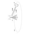
- FIG. 1 is a diagram for explaining a wireless communication system according to an embodiment of the present invention.
- a wireless communication system according to an embodiment of the present invention includes a base station 10 and terminals 20, as shown in FIG. Although one base station 10 and one terminal 20 are shown in FIG. 1, this is an example and there may be more than one.
- the base station 10 is a communication device that provides one or more cells and performs wireless communication with the terminal 20.
- Physical resources of radio signals are defined in the time domain and the frequency domain, the time domain may be defined by the number of OFDM (Orthogonal Frequency Division Multiplexing) symbols, and the frequency domain may be defined by the number of subcarriers or the number of resource blocks. good too.
- a TTI Transmission Time Interval
- a TTI Transmission Time Interval
- TTI Transmission Time Interval
- the base station 10 can perform carrier aggregation in which multiple cells (multiple CCs (component carriers)) are bundled and communicated with the terminal 20 .
- multiple CCs component carriers
- carrier aggregation one primary cell (PCell, Primary Cell) and one or more secondary cells (SCell, Secondary Cell) are used.
- the base station 10 transmits a synchronization signal, system information, etc. to the terminal 20.
- Synchronization signals are, for example, NR-PSS and NR-SSS.
- System information is transmitted, for example, on NR-PBCH or PDSCH, and is also called broadcast information.
- the base station 10 transmits control signals or data to the terminal 20 on DL (Downlink) and receives control signals or data from the terminal 20 on UL (Uplink).
- control channels such as PUCCH and PDCCH
- data what is transmitted on a shared channel such as PUSCH and PDSCH is called data.
- the terminal 20 is a communication device with a wireless communication function, such as a smartphone, mobile phone, tablet, wearable terminal, or M2M (Machine-to-Machine) communication module. As shown in FIG. 1 , the terminal 20 receives control signals or data from the base station 10 on the DL and transmits control signals or data to the base station 10 on the UL, thereby performing various functions provided by the wireless communication system. Use communication services. Note that the terminal 20 may be called UE, and the base station 10 may be called gNB.
- the terminal 20 can perform carrier aggregation in which multiple cells (multiple CCs) are bundled and communicated with the base station 10 .
- Multiple CCs multiple CCs
- One primary cell and one or more secondary cells are used in carrier aggregation.
- a PUCCH-SCell with PUCCH may also be used.
- HARQ-ACK Hybrid automatic repeat request - Acknowledgment
- the network can request the terminal to retransmit HARQ-ACK.
- Retransmission of HARQ-ACK to the terminal 20 may be one-shot triggered by the DL grant DCI (Downlink Control Information).
- One-shot triggering of retransmission may mean triggering (requesting terminal 20 ) one retransmission.
- a single DCI with one-shot triggering may trigger retransmission of only one HARQ-ACK codebook.
- terminal 20 may not assume retransmission of a HARQ-ACK codebook in a PUCCH slot different from the PUCCH slot of the HARQ-ACK codebook to be retransmitted in a PUCCH slot in which retransmission is performed.
- FIG. 2 is a diagram showing an example (1) of HARQ-ACK retransmission.
- the PUCCH containing HARQ-ACK to be retransmitted may be specified by an offset from the slot containing the DCI that triggers the retransmission.
- the offset is -1, and the PUCCH one slot before the slot in which the DCI that triggers retransmission is received is retransmitted.
- FIG. 3 is a diagram showing an example (2) of HARQ-ACK retransmission.
- the PUCCH containing the retransmitted HARQ-ACK may be specified by the offset from the slot in which the PUCCH is retransmitted.
- offset X
- PUCCH in slot NX which is X slots before slot N where PUCCH is retransmitted, is retransmitted.
- the HARQ-ACK to retransmit may be determined based on the slot and physical layer priority of the HARQ-ACK to retransmit.
- DCI-triggered HARQ-ACK retransmissions for one-shot triggering HARQ-ACK retransmissions are limited within the same PUCCH cell group, or are also applied between different PUCCH cell groups. There is a need. For example, it is necessary to determine the interpretation of slot offset values.
- HARQ-ACK is retransmitted in cells other than PCell, PSCell, and PUCCH-SCell. For example, it needs to decide whether it is allowed to enable PUCCH carrier switching for one-shot triggered HARQ-ACK retransmissions. For example, it needs to decide how to determine the cell from which the retransmitted HARQ-ACK was sent. For example, if PUCCH carrier switching is enabled, the impact on the interpretation of slot offset values should be considered.
- FIG. 4 is a diagram for explaining an example of HARQ-ACK retransmission.
- a slot in which a retransmitted HARQ-ACK is transmitted and a cell in which a retransmitted HARQ-ACK is transmitted may be defined.
- HARQ-ACK may be replaced with HARQ-ACK codebook or HARQ-ACK CB (Codebook) hereinafter.
- a slot in which PUCCH is newly retransmitted and a cell in which PUCCH is newly retransmitted may be defined. Also, as shown in FIG.
- a slot for newly retransmitting PUCCH may be specified with a K1 value from DCI that triggers one-shot HARQ-ACK retransmission.
- the slot offset value corresponds from the slot in which the HARQ-ACK to be retransmitted is transmitted to the DCI that triggers one-shot HARQ-ACK retransmission or the slot that newly retransmits PUCCH. You may That is, two points that can be referred to in defining the slot offset may be DCI for one-shot triggering HARQ-ACK retransmission and a slot for newly retransmitting PUCCH.
- Retransmission of HARQ-ACK may be performed at the timing instructed by the base station 10 (for example, slot n+k).
- k is the K1 value signaled by the DCI for one-shot triggering retransmissions
- slot n is the slot that receives the DCI for one-shot triggering retransmissions. It may be assumed that terminal 20 transmits PUCCH to be newly retransmitted after X symbols from the last symbol in which PDCCH of DCI for one-shot triggering of retransmission is received. That is, it is assumed that the K1 value does not indicate that the terminal 20 transmits a newly retransmitted PUCCH before X symbols after the last symbol for receiving the PDCCH of DCI for one-shot triggering retransmission. good too.
- X may be defined in the specification or configured by RRC signaling. X may depend on the UE capabilities and may be associated with the smallest SCS of the PDCCH triggering retransmission and the PUCCH SCS for the new retransmission. Note that a slot for receiving DCI and a slot for receiving PDCCH may be interchangeable.
- the terminal 20 In determining the HARQ-ACK to be retransmitted, the terminal 20 retransmits the HARQ-ACK transmitted in a PUCCH cell group different from the PUCCH cell group associated with the cell in which the DCI that one-shot triggers the retransmission is transmitted is transmitted by the DCI. One-shot triggering may not be assumed. If PUCCH carrier switching is disabled, the cell that retransmits HARQ-ACK is transmitted is either PCell, PSCell or PUCCH-SCell that is the same PUCCH cell group as the cell that DCI that triggers retransmission is always transmitted. There may be.
- the terminal 20 retransmits HARQ-ACK transmitted in a PUCCH cell group different from the PUCCH cell group associated with the DCI that one-shot triggers retransmission. It may be assumed to be ringed.
- the cell in which the retransmitted HARQ-ACK was transmitted may be explicitly notified by the DCI field, or may be set by RRC signaling. For example, when DCI that triggers retransmission is transmitted in cell #1, the DCI may always trigger retransmission of HARQ-ACK in CC #n, or retransmission of HARQ-ACK in PUCCH cell group #i. May be triggered.
- the slot offset value signaled by the DCI that triggers retransmission may be interpreted based on the reference cell numerology (eg, SCS).
- the reference cell may be a cell shown in 1)-9) below.
- the default reference cell may be configured by RRC signaling.
- the default reference cell may be set by setting a candidate cell by RRC signaling and selecting a cell that retransmits HARQ-ACK from the candidate cell by DCI.
- It may be the cell with the highest cell ID or the lowest cell ID among all cells. For example, it may be the cell having the largest cell ID or the smallest cell ID among the cells included in the same PUCCH cell group. For example, among the cells of 1), 2) and 3) above, the cell having the maximum cell ID or the minimum cell ID may be used.
- 8) Among all cells it may be the cell in which the maximum SCS or the minimum SCS is set.
- the cell included in the same PUCCH cell group it may be a cell in which the maximum SCS or the minimum SCS is configured.
- the cell in which the maximum SCS or the minimum SCS is set may be used.
- DCI cells that trigger retransmissions cells that transmit HARQ-ACKs that retransmit, cells that transmit retransmissions, PUCCH cells that transmit retransmissions, PCell, PSCell, and SCS of PUCCH-SCell, SCS is greater or SCS is greater It may be the cell with the largest cell ID or the smallest cell ID among cells with smaller or equal SCS.
- the cell and slot in which the retransmitted HARQ-ACK was transmitted may be determined by performing steps 1 and 2 below.
- the reference point may be a DCI slot and cell that triggers HARQ-ACK retransmission, or a PUCCH slot and cell that is retransmitted.
- Step 1) Determine the slot in the reference cell with an offset equal to the signaled slot offset for the reference point. Furthermore, the following two cases may be assumed.
- the reference cell for interpreting the slot offset value is the cell of the reference point that defines the slot offset.
- the reference cell is a PCell, PSCell or PUCCH-SCell of the same PUCCH cell group as the DCI cell that triggers the retransmission and the slot offset is defined for the retransmission PUCCH.
- the reference cell is a retransmission-triggering DCI cell and a slot offset is defined for the retransmission-triggering DCI cell.
- the reference cell for interpreting the slot offset value is different from the cell of the reference point that defines the slot offset.
- the reference cell is a PCell, PSCell or PUCCH-SCell of the same PUCCH cell group as the cell of the DCI that triggers the retransmission and the slot offset is defined for the DCI that triggers the retransmission.
- the reference cell is a DCI cell that triggers a retransmission and a slot offset is defined for the retransmitted PUCCH.
- slot offset 0 may mean the slot of the reference cell that overlaps with the start or end of DCI reception, or if the slot offset is defined for DCI that triggers retransmission, the DCI reception slot.
- slot offset 0 may mean the slot of the reference cell that overlaps with the start or end of the retransmitted PUCCH slot, if the slot offset is defined for the retransmitted PUCCH.
- Step 2 Determine the slot in which the retransmitting HARQ-ACK was transmitted in the cell in which the retransmitting HARQ-ACK was transmitted. Furthermore, the following two cases may be assumed.
- Case B If the reference cell retransmitting HARQ-ACK is different from the transmitted cell. If the SCS of the cell in which the retransmitting HARQ-ACK was transmitted is less than or equal to the SCS of the reference cell, the slot in which the retransmitting HARQ-ACK was transmitted is the slot of the reference cell determined based on the slot offset indication. It may be the slot of the cell in which the overlapping retransmission HARQ-ACK was sent. In addition, if the SCS of the cell in which the retransmitted HARQ-ACK is transmitted is greater than the SCS of the reference cell, the slot in which the retransmitted HARQ-ACK is transmitted is the slot of the reference cell determined based on the indication of the slot offset. It may be the first or last slot of the plurality of slots of the cell in which the retransmitted HARQ-ACK that overlaps with the HARQ-ACK is transmitted.
- FIG. 5 is a diagram showing an example (1) of HARQ-ACK retransmission in the embodiment of the present invention.
- FIG. 5 shows an example in which step 1 corresponds to case 2 and step 2 corresponds to case A.
- the slot offset reference point is defined by the DCI reception that triggers the retransmission.
- the reference cell is the PCell, PSCell or PUCCH-SCell of the same PUCCH cell group as the DCI cell that triggers the retransmission.
- DCI that triggers retransmission is transmitted on CC#1.
- the PCell which is the reference cell
- a slot with a slot offset of 2 from the slot overlapping the DCI that triggers retransmission is determined.
- the slot determined in step 1 becomes the slot determined in step 2 because the reference cell is the cell that transmitted the retransmitted HARQ-ACK.
- FIG. 6 is a diagram showing an example (2) of HARQ-ACK retransmission in the embodiment of the present invention.
- FIG. 6 shows an example in which step 1 corresponds to case 1 and step 2 corresponds to case A.
- the slot offset reference point is defined by the retransmitting PUCCH.
- the reference cell is the PCell, PSCell or PUCCH-SCell of the same PUCCH cell group as the DCI cell that triggers the retransmission.
- DCI that triggers retransmission is transmitted on CC#1.
- the PCell which is the reference cell
- a slot with a slot offset of 2 from the PUCCH slot for transmitting retransmissions is determined.
- the slot determined in step 1 becomes the slot determined in step 2 because the reference cell is the cell that transmitted the retransmitted HARQ-ACK.
- FIG. 7 is a diagram showing an example (3) of HARQ-ACK retransmission in the embodiment of the present invention.
- FIG. 7 shows an example in which the above step 1 is case 1 and the step 2 is case B above.
- the slot offset reference point is defined by the DCI that triggers the retransmission.
- a reference cell is a DCI cell that triggers a retransmission.
- DCI that triggers retransmission is transmitted in CC#1.
- CC#1 which is the reference cell, a slot with a slot offset of 2 from the DCI slot that triggers retransmission is determined.
- step 2 the slot of the PCell in which the HARQ-ACK was transmitted that overlaps with the slot determined in step 1 in the reference cell becomes the slot determined in step 2.
- the reference cell differs from the cell in which the retransmitted HARQ-ACK was transmitted, and the SCS of CC#1, which is the reference cell, is larger than the PCell that retransmits the HARQ-ACK.
- FIG. 8 is a diagram showing an example (4) of HARQ-ACK retransmission in the embodiment of the present invention.
- FIG. 8 shows an example in which the above step 1 is case 1 and the step 2 is case B above.
- the slot offset reference point is defined by the DCI that triggers the retransmission.
- a reference cell is a DCI cell that triggers a retransmission.
- DCI that triggers retransmission is transmitted in CC#1.
- CC#1 which is the reference cell, a slot with a slot offset of 2 from the DCI slot that triggers retransmission is determined.
- step 2 among a plurality of slots of the PCell in which the HARQ-ACK is transmitted that overlaps with the slot determined in step 1 in the reference cell, the last slot becomes the slot determined in step 2.
- the reference cell differs from the cell in which the retransmitted HARQ-ACK was transmitted, and the SCS of CC#1, which is the reference cell, is smaller than the PCell that retransmits the HARQ-ACK.
- Terminal 20 may not assume that one-shot triggering of HARQ-ACK retransmissions is enabled by any DCI format at the same time when dynamic or semi-static PUCCH carrier switching is enabled. Also, when dynamic or semi-static PUCCH carrier switching is enabled, at the same time either DCI format may allow one-shot triggering of HARQ-ACK retransmissions to be enabled.
- Terminal 20 may not assume that one-shot triggering of HARQ-ACK retransmissions is enabled by any DCI format at the same time when dynamic PUCCH carrier switching is enabled. Also, when dynamic PUCCH carrier switching is enabled, one-shot triggering of HARQ-ACK retransmissions may be enabled by either DCI format at the same time.
- Terminal 20 may not assume that one-shot triggering of HARQ-ACK retransmissions is enabled by any DCI format at the same time when semi-static PUCCH carrier switching is enabled. Also, when semi-static PUCCH carrier switching is enabled, at the same time either DCI format may allow one-shot triggering of HARQ-ACK retransmissions to be enabled.
- Terminal 20 may not assume that one-shot triggering of HARQ-ACK retransmissions is enabled by either DCI format at the same time when dynamic and semi-static PUCCH carrier switching is enabled. Also, one-shot triggering of HARQ-ACK retransmissions may be allowed to be enabled by either DCI format at the same time when dynamic and semi-static PUCCH carrier switching is enabled.
- the DCI format that triggers retransmission of HARQ-ACK and the DCI format that indicates dynamic PUCCH carrier switching may be different DCI formats.
- DCI formats that trigger HARQ-ACK retransmissions may not enable dynamic PUCCH carrier switching.
- terminal 20 may not assume that dynamic PUCCH carrier switching is enabled by DCI formats that trigger HARQ-ACK retransmissions.
- a DCI format that enables dynamic PUCCH carrier switching may not be able to trigger HARQ-ACK retransmissions.
- terminal 20 may not assume that a DCI format that enables dynamic PUCCH carrier switching will trigger a HARQ-ACK retransmission.
- the DCI format that triggers retransmission of HARQ-ACK and the DCI format that instructs dynamic PUCCH carrier switching may be the same DCI format.
- dynamic PUCCH carrier switching may be enabled by DCI formats that trigger HARQ-ACK retransmissions.
- terminal 20 may assume that dynamic PUCCH carrier switching is enabled by DCI formats that trigger HARQ-ACK retransmissions.
- DCI formats that enable dynamic PUCCH carrier switching may trigger HARQ-ACK retransmissions.
- terminal 20 may assume that HARQ-ACK retransmissions are triggered by DCI formats that enable dynamic PUCCH carrier switching.
- a cell may be explicitly signaled by a field of the DCI format.
- the DCI format fields may be new DCI fields or may be based on reinterpretation of existing fields (eg HPN, FDRA, TDRA, RV, MCS, etc.).
- the new DCI field is HARQ- May be configured to enable one-shot triggering of ACK retransmissions.
- the existing field may be interpreted to indicate the cell from which the retransmitting HARQ-ACK was sent.
- the DCI field may directly notify the cell ID of the cell from which the retransmitted HARQ-ACK was transmitted, or may notify the index of the cell included in the list of possible PUCCH cells.
- the list of possible PUCCH cells may be configured by RRC signaling.
- terminal 20 does not assume that the cell in which the retransmitted HARQ-ACK indicated by the DCI field was transmitted and the cell in which the HARQ-ACK is newly retransmitted belong to different PUCCH cell groups. good.
- the terminal 20 does not have to assume that the cell in which the retransmitted HARQ-ACK indicated by the DCI field was transmitted and the cell of the DCI that triggers the retransmission belong to different PUCCH cell groups.
- the terminal 20 does not have to assume that the cell in which the retransmitted HARQ-ACK notified by the DCI field was transmitted differs from the cell in which the HARQ-ACK is newly retransmitted.
- the terminal 20 does not assume that the SCS of the cell that transmitted the retransmitted HARQ-ACK indicated by the DCI field is larger or smaller than the SCS of the cell that newly retransmits the HARQ-ACK. good.
- the reference cell for determining the slot offset value may be the cell shown in 1) to 12) below.
- SCS is greater or SCS is greater It may be the cell with the largest cell ID or the smallest cell ID among cells with smaller or equal SCS.
- Cells referenced in the PUCCH cell timing pattern if a PUCCH cell timing pattern is configured.
- the cell in which the retransmitted HARQ-ACK was transmitted may be a cell that newly retransmits the HARQ-ACK.
- the cell that newly retransmits HARQ-ACK may be the cell that transmitted the retransmitted HARQ-ACK.
- the target PUCCH cell determined by the PUCCH carrier switching rule may be a cell that newly retransmits HARQ-ACK. If the target PUCCH carrier field is included in the DCI that triggers retransmission, the target PUCCH carrier may be the cell that newly retransmits HARQ-ACK.
- the PUCCH cell based on this PUCCH cell timing may be the cell that newly retransmits HARQ-ACK.
- the cell on which the retransmission HARQ-ACK was sent may be the DCI cell that triggers the retransmission.
- a cell that newly retransmits HARQ-ACK may be a DCI cell that triggers retransmission.
- the cell on which the retransmitting HARQ-ACK was sent may be the default cell below.
- the default cell may be PCell, PSCell and PUCCH-SCell belonging to the same PUCCH cell group as the cell in which the retransmitted HARQ-ACK was transmitted.
- the default cell may be the PUCCH cell configured with the maximum or minimum SCS among all possible PUCCH cells of the same PUCCH cell group as the cell in which the retransmitted HARQ-ACK was transmitted.
- the default cell may be the PUCCH cell configured with the maximum or minimum cell ID among all possible PUCCH cells of the same PUCCH cell group as the cell in which the retransmitted HARQ-ACK was sent.
- the default cell may be the cell or carrier configured by RRC signaling.
- the cell on which the retransmitting HARQ-ACK was sent may be determined based on the slot offset and the PUCCH cell timing pattern, and may be determined by steps A) and B) shown below.
- Step A) Determine the slot in the reference cell based on the reported slot offset value.
- the reference cell for interpretation of the slot offset value may be any of the reference cells described above.
- Step 1 described above may be applied to the method of applying the slot offset value and determining the slot in the reference cell.
- Step B) Determine the cell and slot in which the retransmitted HARQ-ACK was sent. Based on the PUCCH cell pattern, the PUCCH cell mapped to the slot in the reference cell determined in step A may be determined to be the cell where the retransmitted HARQ-ACK was transmitted. Further, case 1) and case 2) shown below may also be applied.
- Case 2 When the SCS of the reference cell is smaller than the SCS of the PUCCH cell pattern notification, the terminal 20 may not assume this case. In addition, assuming this case, terminal 20 may map one or more PUCCH cells to slots in the reference cell. For example, terminal 20 does not have to assume a PUCCH cell different from the reference cell. Also, for example, the terminal 20 may determine the first or last PUCCH cell mapped to a plurality of PUCCH cells mapped to slots in the reference cell as the cell to which the HARQ-ACK to be retransmitted is transmitted. .
- the interpretation of the slot offset and the determination of the cell and slot in which the retransmitted HARQ-ACK was transmitted may be performed by steps 1 and 2 described above.
- FIG. 9 is a diagram showing an example (5) of HARQ-ACK retransmission in the embodiment of the present invention.
- step A the slot in reference cell CC#2 is determined based on the slot offset.
- step B the corresponding PUCCH cell is determined as the PCell based on the PUCCH cell pattern.
- the slot of the PCell that overlaps with the slot determined in step A is determined as the slot in which the retransmitted HARQ-ACK was transmitted.
- FIG. 10 is a diagram showing an example (6) of HARQ-ACK retransmission in the embodiment of the present invention.
- step A the slot in reference cell CC#2 is determined based on the slot offset.
- step B CC#3 is determined as the corresponding PUCCH cell based on the PUCCH cell pattern.
- the last slot is determined as the slot in which the retransmitted HARQ-ACK was transmitted.
- FIG. 11 is a diagram showing an example (7) of HARQ-ACK retransmission in the embodiment of the present invention.
- step A the slot in reference cell CC#2 is determined based on the slot offset.
- step B the corresponding PUCCH cell is determined to be the PCell corresponding to the last cell among the overlapping CC#3 or PCells, based on the PUCCH cell pattern.
- the slot of the PCell that overlaps with the slot determined in step A is determined as the slot in which the retransmitted HARQ-ACK was transmitted.
- Which of the above-described embodiments of the present invention is applied may be set by upper layer parameters, may be reported to the network from terminal 20 as UE capabilities, or may be defined in specifications. and may be reported from the terminal 20 to the network as UE capabilities set by higher layer parameters.
- Slot in the embodiment of the present invention may be replaced with "subslot”.
- PUCCH cell in the embodiment of the present invention may be replaced with "PUCCH carrier” in consideration of PUCCH carrier switching to SUL (Supplementary Uplink).
- UE capability to support one shot triggering of HARQ-ACK retransmissions 1) UE capability to support one shot triggering of HARQ-ACK retransmissions. 2) UE capability to support one shot triggering of HARQ-ACK retransmissions across PUCCH cell groups. 3) UE capability to support PUCCH carrier switching. 4) UE capability to enable simultaneous PUCCH carrier switching and one-shot triggering of HARQ-ACK retransmissions. 5) UE capability to support one-shot triggering of HARQ-ACK retransmissions on different cells where the retransmitting HARQ-ACK was sent and the cell that retransmits the HARQ-ACK.
- the terminal 20 can identify the cell and slot in which the retransmitted HARQ-ACK was transmitted and retransmit the HARQ-ACK based on the DCI instruction.
- the base stations 10 and terminals 20 contain the functionality to implement the embodiments described above. However, each of the base station 10 and the terminal 20 may have only one of the functions of the embodiments.
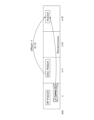
- FIG. 12 is a diagram showing an example of the functional configuration of the base station 10.
- the base station 10 has a transmitting section 110, a receiving section 120, a setting section 130, and a control section 140.
- the functional configuration shown in FIG. 12 is merely an example. As long as the operation according to the embodiment of the present invention can be executed, the functional division and the names of the functional units may be arbitrary.
- the transmitting unit 110 and the receiving unit 120 may be called a communication unit.
- the transmission unit 110 includes a function of generating a signal to be transmitted to the terminal 20 side and wirelessly transmitting the signal.
- the receiving unit 120 includes a function of receiving various signals transmitted from the terminal 20 and acquiring, for example, higher layer information from the received signals.
- the transmitting unit 110 has a function of transmitting NR-PSS, NR-SSS, NR-PBCH, DL/UL control signals, DL data, etc. to the terminal 20 . Also, the transmission unit 110 transmits the setting information and the like described in the embodiment.
- the setting unit 130 stores preset setting information and various setting information to be transmitted to the terminal 20 in the storage device, and reads them from the storage device as necessary.
- the control unit 140 performs, for example, resource allocation, overall control of the base station 10, and the like. It should be noted that the functional unit related to signal transmission in control unit 140 may be included in transmitting unit 110 , and the functional unit related to signal reception in control unit 140 may be included in receiving unit 120 . Also, the transmitting unit 110 and the receiving unit 120 may be called a transmitter and a receiver, respectively.
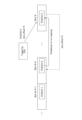
- FIG. 13 is a diagram showing an example of the functional configuration of the terminal 20.
- the terminal 20 has a transmitter 210 , a receiver 220 , a setter 230 and a controller 240 .
- the functional configuration shown in FIG. 13 is merely an example. As long as the operation according to the embodiment of the present invention can be executed, the functional division and the names of the functional units may be arbitrary.
- the transmitting unit 210 and the receiving unit 220 may be called a communication unit.
- the transmission unit 210 creates a transmission signal from the transmission data and wirelessly transmits the transmission signal.
- the receiving unit 220 wirelessly receives various signals and acquires a higher layer signal from the received physical layer signal. Also, the transmitting unit 210 transmits HARQ-ACK, and the receiving unit 220 receives the setting information and the like described in the embodiment.
- the setting unit 230 stores various types of setting information received from the base station 10 by the receiving unit 220 in the storage device, and reads them from the storage device as necessary.
- the setting unit 230 also stores preset setting information.
- the control unit 240 controls the terminal 20 as a whole. It should be noted that the functional unit related to signal transmission in control unit 240 may be included in transmitting unit 210 , and the functional unit related to signal reception in control unit 240 may be included in receiving unit 220 . Also, the transmitting section 210 and the receiving section 220 may be called a transmitter and a receiver, respectively.
- each functional block may be implemented using one device that is physically or logically coupled, or directly or indirectly using two or more devices that are physically or logically separated (e.g. , wired, wireless, etc.) and may be implemented using these multiple devices.
- a functional block may be implemented by combining software in the one device or the plurality of devices.
- Functions include judging, determining, determining, calculating, calculating, processing, deriving, investigating, searching, checking, receiving, transmitting, outputting, accessing, resolving, selecting, choosing, establishing, comparing, assuming, expecting, assuming, broadcasting, notifying, communicating, forwarding, configuring, reconfiguring, allocating, mapping, assigning, etc. can't
- a functional block (component) responsible for transmission is called a transmitting unit or transmitter.
- the implementation method is not particularly limited.
- the base station 10, the terminal 20, etc. may function as a computer that performs processing of the wireless communication method of the present disclosure.
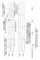
- FIG. 14 is a diagram illustrating an example of hardware configurations of the base station 10 and the terminal 20 according to an embodiment of the present disclosure.
- the base station 10 and terminal 20 described above are physically configured as a computer device including a processor 1001, a storage device 1002, an auxiliary storage device 1003, a communication device 1004, an input device 1005, an output device 1006, a bus 1007, and the like. good too.
- the term "apparatus” can be read as a circuit, device, unit, or the like.
- the hardware configuration of the base station 10 and terminal 20 may be configured to include one or more of each device shown in the figure, or may be configured without some devices.
- Each function of the base station 10 and the terminal 20 is performed by the processor 1001 performing calculations and controlling communication by the communication device 1004 by loading predetermined software (programs) onto hardware such as the processor 1001 and the storage device 1002. or by controlling at least one of data reading and writing in the storage device 1002 and the auxiliary storage device 1003 .
- the processor 1001 for example, operates an operating system and controls the entire computer.
- the processor 1001 may be configured with a central processing unit (CPU) including an interface with peripheral devices, a control device, an arithmetic device, registers, and the like.
- CPU central processing unit
- the control unit 140 , the control unit 240 and the like described above may be implemented by the processor 1001 .
- the processor 1001 reads programs (program codes), software modules, data, etc. from at least one of the auxiliary storage device 1003 and the communication device 1004 to the storage device 1002, and executes various processes according to them.
- programs program codes
- software modules software modules
- data etc.
- the program a program that causes a computer to execute at least part of the operations described in the above embodiments is used.
- control unit 140 of base station 10 shown in FIG. 12 may be implemented by a control program stored in storage device 1002 and operated by processor 1001 .
- the control unit 240 of the terminal 20 shown in FIG. 13 may be implemented by a control program stored in the storage device 1002 and operated by the processor 1001 .
- FIG. Processor 1001 may be implemented by one or more chips. Note that the program may be transmitted from a network via an electric communication line.
- the storage device 1002 is a computer-readable recording medium, for example, ROM (Read Only Memory), EPROM (Erasable Programmable ROM), EEPROM (Electrically Erasable Programmable ROM), RAM (Random Access Memory), etc. may be configured.
- the storage device 1002 may also be called a register, cache, main memory (main storage device), or the like.
- the storage device 1002 can store executable programs (program code), software modules, etc. for implementing a communication method according to an embodiment of the present disclosure.
- the auxiliary storage device 1003 is a computer-readable recording medium, for example, an optical disc such as a CD-ROM (Compact Disc ROM), a hard disk drive, a flexible disc, a magneto-optical disc (for example, a compact disc, a digital versatile disc, a Blu -ray disk), smart card, flash memory (eg, card, stick, key drive), floppy disk, magnetic strip, and/or the like.
- the storage medium described above may be, for example, a database, server, or other suitable medium including at least one of storage device 1002 and secondary storage device 1003 .
- the communication device 1004 is hardware (transmitting/receiving device) for communicating between computers via at least one of a wired network and a wireless network, and is also called a network device, a network controller, a network card, a communication module, or the like.
- the communication device 1004 includes a high-frequency switch, a duplexer, a filter, a frequency synthesizer, etc. in order to realize at least one of, for example, frequency division duplex (FDD) and time division duplex (TDD).
- FDD frequency division duplex
- TDD time division duplex
- the transceiver may be physically or logically separate implementations for the transmitter and receiver.
- the input device 1005 is an input device (for example, keyboard, mouse, microphone, switch, button, sensor, etc.) that receives input from the outside.
- the output device 1006 is an output device (for example, display, speaker, LED lamp, etc.) that outputs to the outside. Note that the input device 1005 and the output device 1006 may be integrated (for example, a touch panel).
- Each device such as the processor 1001 and the storage device 1002 is connected by a bus 1007 for communicating information.
- the bus 1007 may be configured using a single bus, or may be configured using different buses between devices.
- the base station 10 and the terminal 20 include microprocessors, digital signal processors (DSPs), ASICs (Application Specific Integrated Circuits), PLDs (Programmable Logic Devices), FPGAs (Field Programmable Gates and other hardware arrays). , and part or all of each functional block may be implemented by the hardware.
- processor 1001 may be implemented using at least one of these pieces of hardware.
- a vehicle 2001 includes a drive unit 2002, a steering unit 2003, an accelerator pedal 2004, a brake pedal 2005, a shift lever 2006, front wheels 2007, rear wheels 2008, an axle 2009, an electronic control unit 2010, various sensors 2021 to 2029. , an information service unit 2012 and a communication module 2013 .
- a communication device mounted on vehicle 2001 may be applied to communication module 2013, for example.
- the driving unit 2002 is configured by, for example, an engine, a motor, or a hybrid of the engine and the motor.
- the steering unit 2003 includes at least a steering wheel (also referred to as steering wheel), and is configured to steer at least one of the front wheels and the rear wheels based on the operation of the steering wheel operated by the user.
- the electronic control unit 2010 is composed of a microprocessor 2031 , a memory (ROM, RAM) 2032 and a communication port (IO port) 2033 . Signals from various sensors 2021 to 2029 provided in the vehicle 2001 are input to the electronic control unit 2010 .
- the electronic control unit 2010 may also be called an ECU (Electronic Control Unit).
- the signals from the various sensors 2021 to 2029 include the current signal from the current sensor 2021 that senses the current of the motor, the rotation speed signal of the front and rear wheels acquired by the rotation speed sensor 2022, and the front wheel acquired by the air pressure sensor 2023. and rear wheel air pressure signal, vehicle speed signal obtained by vehicle speed sensor 2024, acceleration signal obtained by acceleration sensor 2025, accelerator pedal depression amount signal obtained by accelerator pedal sensor 2029, brake pedal sensor 2026 obtained by There are a brake pedal depression amount signal, a shift lever operation signal acquired by the shift lever sensor 2027, and a detection signal for detecting obstacles, vehicles, pedestrians, etc. acquired by the object detection sensor 2028, and the like.
- the information service unit 2012 includes various devices such as car navigation systems, audio systems, speakers, televisions, and radios for providing various types of information such as driving information, traffic information, and entertainment information, and one or more devices for controlling these devices. ECU.
- the information service unit 2012 uses information acquired from an external device via the communication module 2013 or the like to provide passengers of the vehicle 2001 with various multimedia information and multimedia services.
- Driving support system unit 2030 includes millimeter wave radar, LiDAR (Light Detection and Ranging), camera, positioning locator (e.g., GNSS, etc.), map information (e.g., high-definition (HD) map, automatic driving vehicle (AV) map, etc. ), gyro systems (e.g., IMU (Inertial Measurement Unit), INS (Inertial Navigation System), etc.), AI (Artificial Intelligence) chips, AI processors, etc., to prevent accidents and reduce the driver's driving load. and one or more ECUs for controlling these devices.
- the driving support system unit 2030 transmits and receives various information via the communication module 2013, and realizes a driving support function or an automatic driving function.
- the communication module 2013 can communicate with the microprocessor 2031 and components of the vehicle 2001 via communication ports.
- the communication module 2013 communicates with the vehicle 2001 through the communication port 2033, the drive unit 2002, the steering unit 2003, the accelerator pedal 2004, the brake pedal 2005, the shift lever 2006, the front wheels 2007, the rear wheels 2008, the axle 2009, the electronic Data is transmitted and received between the microprocessor 2031 and memory (ROM, RAM) 2032 in the control unit 2010 and the sensors 2021-29.
- the communication module 2013 is a communication device that can be controlled by the microprocessor 2031 of the electronic control unit 2010 and can communicate with an external device. For example, it transmits and receives various information to and from an external device via wireless communication.
- Communication module 2013 may be internal or external to electronic control unit 2010 .
- the external device may be, for example, a base station, a mobile station, or the like.
- the communication module 2013 transmits the current signal from the current sensor input to the electronic control unit 2010 to an external device via wireless communication.
- the communication module 2013 receives, from the electronic control unit 2010, the rotation speed signals of the front and rear wheels obtained by the rotation speed sensor 2022, the air pressure signals of the front and rear wheels obtained by the air pressure sensor 2023, and the vehicle speed sensor. 2024, an acceleration signal obtained by an acceleration sensor 2025, an accelerator pedal depression amount signal obtained by an accelerator pedal sensor 2029, a brake pedal depression amount signal obtained by a brake pedal sensor 2026, and a shift lever.
- a shift lever operation signal obtained by the sensor 2027 and a detection signal for detecting obstacles, vehicles, pedestrians, etc. obtained by the object detection sensor 2028 are also transmitted to an external device via wireless communication.
- the communication module 2013 receives various information (traffic information, signal information, inter-vehicle information, etc.) transmitted from external devices, and displays it on the information service unit 2012 provided in the vehicle 2001 .
- Communication module 2013 also stores various information received from external devices in memory 2032 available to microprocessor 2031 .
- the microprocessor 2031 controls the drive unit 2002, the steering unit 2003, the accelerator pedal 2004, the brake pedal 2005, the shift lever 2006, the front wheels 2007, the rear wheels 2008, and the axle 2009 provided in the vehicle 2001.
- sensors 2021 to 2029 and the like may be controlled.
- a transmission unit that transmits a HARQ (Hybrid automatic repeat request) response to a base station, and control information that triggers retransmission of the HARQ response from the base station and a control unit that determines the HARQ response to be retransmitted based on the control information, the control unit determining a cell to which the slot offset included in the control information is applied, applying a slot offset to the cell to determine a first slot in the cell; based on the first slot, determining a cell and a second slot in which the HARQ response to retransmit was transmitted; A section is provided with the terminal retransmitting the determined HARQ response to the base station.
- HARQ Hybrid automatic repeat request
- the terminal 20 can identify the cell and slot in which the HARQ-ACK to be retransmitted has been transmitted and retransmit the HARQ-ACK based on the DCI instruction. That is, in a radio communication system, it is possible to retransmit a response related to retransmission control.
- the control unit may assume that the cell to which the slot offset is applied is the cell that retransmits the determined HARQ response or the cell that received the control information.
- the terminal 20 can identify the cell and slot in which the HARQ-ACK to be retransmitted was transmitted and retransmit the HARQ-ACK, based on the DCI instruction.
- the control unit sets the first slot or the last slot among the plurality of slots to the second slot. may decide.
- the terminal 20 can identify the cell and slot in which the HARQ-ACK to be retransmitted was transmitted and retransmit the HARQ-ACK, based on the DCI instruction.
- the control unit may determine the cell in which the HARQ response to be retransmitted was transmitted based on a PUCCH (Physical Uplink Control Channel) cell pattern.
- PUCCH Physical Uplink Control Channel
- the control unit determines the cell to which the HARQ response for retransmitting the first or last cell among the plurality of cells is transmitted. You may With this configuration, the terminal 20 can identify the cell and slot in which the HARQ-ACK to be retransmitted was transmitted and retransmit the HARQ-ACK, based on the DCI instruction.
- a transmission procedure for transmitting a HARQ (Hybrid Automatic Repeat Request) response to a base station and a reception procedure for receiving control information that triggers retransmission of the HARQ response from the base station.
- determine a control procedure for determining the HARQ response to be retransmitted determine a cell to which the slot offset included in the control information is applied, apply the slot offset to the cell, and perform the first determining a slot and, based on the first slot, determining a cell and a second slot in which the HARQ response to be retransmitted was transmitted; and retransmitting the determined HARQ response to the base station.
- a communication method is provided in which a terminal performs a procedure.
- the terminal 20 can identify the cell and slot in which the HARQ-ACK to be retransmitted has been transmitted and retransmit the HARQ-ACK based on the DCI instruction. That is, in a radio communication system, it is possible to retransmit a response related to retransmission control.
- the operations of a plurality of functional units may be physically performed by one component, or the operations of one functional unit may be physically performed by a plurality of components.
- the processing order may be changed as long as there is no contradiction.
- the base station 10 and the terminal 20 have been described using functional block diagrams for convenience of explanation of processing, such devices may be implemented in hardware, software, or a combination thereof.
- the software operated by the processor of the base station 10 according to the embodiment of the present invention and the software operated by the processor of the terminal 20 according to the embodiment of the present invention are stored in random access memory (RAM), flash memory, read-only memory, respectively. (ROM), EPROM, EEPROM, register, hard disk (HDD), removable disk, CD-ROM, database, server, or any other appropriate storage medium.
- notification of information is not limited to the aspects/embodiments described in the present disclosure, and may be performed using other methods.
- notification of information includes physical layer signaling (e.g., DCI (Downlink Control Information), UCI (Uplink Control Information)), higher layer signaling (e.g., RRC (Radio Resource Control) signaling, MAC (Medium Access Control) signaling, It may be implemented by broadcast information (MIB (Master Information Block), SIB (System Information Block)), other signals, or a combination thereof.
- RRC signaling may also be called an RRC message, for example, RRC It may be a connection setup (RRC Connection Setup) message, an RRC connection reconfiguration message, or the like.
- Each aspect/embodiment described in the present disclosure includes LTE (Long Term Evolution), LTE-A (LTE-Advanced), SUPER 3G, IMT-Advanced, 4G (4th generation mobile communication system), 5G (5th generation mobile communication system) system), 6th generation mobile communication system (6G), xth generation mobile communication system (xG) (xG (x is, for example, an integer, a decimal number)), FRA (Future Radio Access), NR (new Radio), New radio access ( NX), Future generation radio access (FX), W-CDMA (registered trademark), GSM (registered trademark), CDMA2000, UMB (Ultra Mobile Broadband), IEEE 802.11 (Wi-Fi (registered trademark)), IEEE 802 .16 (WiMAX (registered trademark)), IEEE 802.20, UWB (Ultra-WideBand), Bluetooth (registered trademark), and other suitable systems, and any extensions, modifications, creations, and provisions based on these systems. It may be applied to
- a specific operation performed by the base station 10 in this specification may be performed by its upper node in some cases.
- various operations performed for communication with terminal 20 may be performed by base station 10 and other network nodes other than base station 10 (eg, but not limited to MME or S-GW).
- base station 10 e.g, but not limited to MME or S-GW
- the other network node may be a combination of a plurality of other network nodes (for example, MME and S-GW).
- Information, signals, etc. described in the present disclosure may be output from a higher layer (or a lower layer) to a lower layer (or a higher layer). It may be input and output via multiple network nodes.
- Input/output information may be stored in a specific location (for example, memory) or managed using a management table. Input/output information and the like can be overwritten, updated, or appended. The output information and the like may be deleted. The entered information and the like may be transmitted to another device.
- the determination in the present disclosure may be performed by a value represented by 1 bit (0 or 1), may be performed by a boolean value (Boolean: true or false), or may be performed by comparing numerical values (e.g. , comparison with a predetermined value).
- Software whether referred to as software, firmware, middleware, microcode, hardware description language or otherwise, includes instructions, instruction sets, code, code segments, program code, programs, subprograms, and software modules. , applications, software applications, software packages, routines, subroutines, objects, executables, threads of execution, procedures, functions, and the like.
- software, instructions, information, etc. may be transmitted and received via a transmission medium.
- the software uses at least one of wired technology (coaxial cable, fiber optic cable, twisted pair, digital subscriber line (DSL), etc.) and wireless technology (infrared, microwave, etc.) to website, Wired and/or wireless technologies are included within the definition of transmission medium when sent from a server or other remote source.
- wired technology coaxial cable, fiber optic cable, twisted pair, digital subscriber line (DSL), etc.
- wireless technology infrared, microwave, etc.
- data, instructions, commands, information, signals, bits, symbols, chips, etc. may refer to voltages, currents, electromagnetic waves, magnetic fields or magnetic particles, light fields or photons, or any of these. may be represented by a combination of
- the channel and/or symbols may be signaling.
- a signal may also be a message.
- a component carrier may also be called a carrier frequency, a cell, a frequency carrier, or the like.
- system and “network” used in this disclosure are used interchangeably.
- information, parameters, etc. described in the present disclosure may be expressed using absolute values, may be expressed using relative values from a predetermined value, or may be expressed using other corresponding information.
- radio resources may be indexed.
- base station BS
- radio base station base station
- base station fixed station
- NodeB nodeB
- eNodeB eNodeB
- gNodeB gNodeB
- a base station can accommodate one or more (eg, three) cells.
- the overall coverage area of the base station can be partitioned into multiple smaller areas, each smaller area being associated with a base station subsystem (e.g., an indoor small base station (RRH:
- RRH indoor small base station
- the term "cell” or “sector” refers to part or all of the coverage area of at least one of the base stations and base station subsystems serving communication services in this coverage.
- MS Mobile Station
- UE User Equipment
- a mobile station is defined by those skilled in the art as a subscriber station, mobile unit, subscriber unit, wireless unit, remote unit, mobile device, wireless device, wireless communication device, remote device, mobile subscriber station, access terminal, mobile terminal, wireless It may also be called a terminal, remote terminal, handset, user agent, mobile client, client, or some other suitable term.
- At least one of the base station and mobile station may be called a transmitting device, a receiving device, a communication device, or the like.
- At least one of the base station and the mobile station may be a device mounted on a mobile object, the mobile object itself, or the like.
- the mobile object may be a vehicle (e.g., car, airplane, etc.), an unmanned mobile object (e.g., drone, self-driving car, etc.), or a robot (manned or unmanned ).
- at least one of the base station and the mobile station includes devices that do not necessarily move during communication operations.
- at least one of the base station and mobile station may be an IoT (Internet of Things) device such as a sensor.
- IoT Internet of Things
- the base station in the present disclosure may be read as a user terminal.
- communication between a base station and a user terminal is replaced with communication between a plurality of terminals 20 (for example, D2D (Device-to-Device), V2X (Vehicle-to-Everything), etc.)
- the terminal 20 may have the functions of the base station 10 described above.
- words such as "up” and “down” may be replaced with words corresponding to inter-terminal communication (for example, "side”).
- uplink channels, downlink channels, etc. may be read as side channels.
- user terminals in the present disclosure may be read as base stations.
- the base station may have the functions that the above-described user terminal has.
- determining and “determining” used in this disclosure may encompass a wide variety of actions.
- “Judgement” and “determination” are, for example, judging, calculating, computing, processing, deriving, investigating, looking up, searching, inquiring (eg, lookup in a table, database, or other data structure), ascertaining as “judged” or “determined”, and the like.
- "judgment” and “determination” are used for receiving (e.g., receiving information), transmitting (e.g., transmitting information), input, output, access (accessing) (for example, accessing data in memory) may include deeming that a "judgment” or “decision” has been made.
- judgment and “decision” are considered to be “judgment” and “decision” by resolving, selecting, choosing, establishing, comparing, etc. can contain.
- judgment and “decision” may include considering that some action is “judgment” and “decision”.
- judgment (decision) may be read as “assuming”, “expecting”, “considering”, or the like.
- connection means any direct or indirect connection or coupling between two or more elements, It can include the presence of one or more intermediate elements between two elements being “connected” or “coupled.” Couplings or connections between elements may be physical, logical, or a combination thereof. For example, “connection” may be read as "access”.
- two elements are defined using at least one of one or more wires, cables, and printed electrical connections and, as some non-limiting and non-exhaustive examples, in the radio frequency domain. , electromagnetic energy having wavelengths in the microwave and optical (both visible and invisible) regions, and the like.
- the reference signal can also be abbreviated as RS (Reference Signal), and may also be called Pilot depending on the applicable standard.
- RS Reference Signal
- any reference to elements using the "first,” “second,” etc. designations used in this disclosure does not generally limit the quantity or order of those elements. These designations may be used in this disclosure as a convenient method of distinguishing between two or more elements. Thus, reference to a first and second element does not imply that only two elements can be employed or that the first element must precede the second element in any way.
- a radio frame may consist of one or more frames in the time domain. Each frame or frames in the time domain may be referred to as a subframe. A subframe may also consist of one or more slots in the time domain. A subframe may be of a fixed length of time (eg, 1 ms) independent of numerology.
- a numerology may be a communication parameter that applies to the transmission and/or reception of a signal or channel. Numerology, for example, subcarrier spacing (SCS), bandwidth, symbol length, cyclic prefix length, transmission time interval (TTI), number of symbols per TTI, radio frame structure, transceiver It may indicate at least one of certain filtering operations performed in the frequency domain, certain windowing operations performed by the transceiver in the time domain, and/or the like.
- SCS subcarrier spacing
- TTI transmission time interval
- transceiver It may indicate at least one of certain filtering operations performed in the frequency domain, certain windowing operations performed by the transceiver in the time domain, and/or the like.
- a slot may consist of one or more symbols (OFDM (Orthogonal Frequency Division Multiplexing) symbol, SC-FDMA (Single Carrier Frequency Division Multiple Access) symbol, etc.) in the time domain.
- a slot may be a unit of time based on numerology.
- a slot may contain multiple mini-slots. Each minislot may consist of one or more symbols in the time domain. A minislot may also be referred to as a subslot. A minislot may consist of fewer symbols than a slot.
- PDSCH (or PUSCH) transmitted in time units larger than minislots may be referred to as PDSCH (or PUSCH) mapping type A.
- PDSCH (or PUSCH) transmitted using minislots may be referred to as PDSCH (or PUSCH) mapping type B.
- Radio frames, subframes, slots, minislots and symbols all represent time units when transmitting signals. Radio frames, subframes, slots, minislots and symbols may be referred to by other corresponding designations.
- one subframe may be called a Transmission Time Interval (TTI)
- TTI Transmission Time Interval
- multiple consecutive subframes may be called a TTI
- one slot or minislot may be called a TTI.
- TTI Transmission Time Interval
- at least one of the subframe and TTI may be a subframe (1 ms) in existing LTE, a period shorter than 1 ms (eg, 1-13 symbols), or a period longer than 1 ms may be Note that the unit representing the TTI may be called a slot, mini-slot, or the like instead of a subframe.
- TTI refers to, for example, the minimum scheduling time unit in wireless communication.
- the base station performs scheduling to allocate radio resources (frequency bandwidth, transmission power, etc. that can be used by each terminal 20) to each terminal 20 on a TTI basis.
- radio resources frequency bandwidth, transmission power, etc. that can be used by each terminal 20
- TTI is not limited to this.
- a TTI may be a transmission time unit such as a channel-encoded data packet (transport block), code block, or codeword, or may be a processing unit such as scheduling and link adaptation. Note that when a TTI is given, the time interval (for example, the number of symbols) in which transport blocks, code blocks, codewords, etc. are actually mapped may be shorter than the TTI.
- one or more TTIs may be the minimum scheduling time unit. Also, the number of slots (the number of mini-slots) constituting the minimum time unit of the scheduling may be controlled.
- a TTI having a time length of 1 ms may be called a normal TTI (TTI in LTE Rel. 8-12), normal TTI, long TTI, normal subframe, normal subframe, long subframe, slot, or the like.
- a TTI that is shorter than a normal TTI may be called a shortened TTI, a short TTI, a partial or fractional TTI, a shortened subframe, a short subframe, a minislot, a subslot, a slot, and the like.
- the long TTI (e.g., normal TTI, subframe, etc.) may be replaced with a TTI having a time length exceeding 1 ms
- the short TTI e.g., shortened TTI, etc.
- a TTI having the above TTI length may be read instead.
- a resource block is a resource allocation unit in the time domain and the frequency domain, and may include one or more consecutive subcarriers in the frequency domain.
- the number of subcarriers included in the RB may be the same regardless of the numerology, and may be 12, for example.
- the number of subcarriers included in an RB may be determined based on numerology.
- the time domain of an RB may include one or more symbols and may be 1 slot, 1 minislot, 1 subframe, or 1 TTI long.
- One TTI, one subframe, etc. may each consist of one or more resource blocks.
- One or more RBs are physical resource blocks (PRBs), sub-carrier groups (SCGs), resource element groups (REGs), PRB pairs, RB pairs, etc. may be called.
- PRBs physical resource blocks
- SCGs sub-carrier groups
- REGs resource element groups
- PRB pairs RB pairs, etc. may be called.
- a resource block may be composed of one or more resource elements (RE: Resource Element).
- RE Resource Element
- 1 RE may be a radio resource region of 1 subcarrier and 1 symbol.
- a bandwidth part (which may also be called a bandwidth part) may represent a subset of contiguous common resource blocks (RBs) for a certain numerology on a certain carrier.
- the common RB may be identified by an RB index based on the common reference point of the carrier.
- PRBs may be defined in a BWP and numbered within that BWP.
- the BWP may include a BWP for UL (UL BWP) and a BWP for DL (DL BWP).
- UL BWP UL BWP
- DL BWP DL BWP
- One or more BWPs may be configured for terminal 20 within one carrier.
- At least one of the configured BWPs may be active, and the terminal 20 may not expect to transmit or receive a given signal/channel outside the active BWP.
- “cell”, “carrier”, etc. in the present disclosure may be read as "BWP”.
- radio frames, subframes, slots, minislots and symbols described above are only examples.
- the number of subframes contained in a radio frame the number of slots per subframe or radio frame, the number of minislots contained within a slot, the number of symbols and RBs contained in a slot or minislot, the number of Configurations such as the number of subcarriers, the number of symbols in a TTI, the symbol length, the cyclic prefix (CP) length, etc.
- CP cyclic prefix
- a and B are different may mean “A and B are different from each other.”
- the term may also mean that "A and B are different from C”.
- Terms such as “separate,” “coupled,” etc. may also be interpreted in the same manner as “different.”
- notification of predetermined information is not limited to being performed explicitly, but may be performed implicitly (for example, not notifying the predetermined information). good too.
Abstract
This terminal includes: a transmission unit that transmits a hybrid automatic repeat request (HARQ) response to a base station; a reception unit that receives, from the base station, control information for triggering re-transmission of the HARQ response; and a control unit that determines the HARQ response to be re-transmitted on the basis of the control information. The control unit determines a cell to which a slot offset included in the control information is to be applied, and determines a first slot in the cell by applying the slot offset to the cell. On the basis of the first slot, the control unit determines a cell and a second slot to which the re-transmitted HARQ response is transmitted, and the transmission unit re-transmits the determined HARQ response to the base station.
Description
本発明は、無線通信システムにおける端末及び通信方法に関連する。
The present invention relates to a terminal and communication method in a wireless communication system.
3GPP(3rd Generation Partnership Project)では、システム容量の更なる大容量化、データ伝送速度の更なる高速化、無線区間における更なる低遅延化等を実現するために、5GあるいはNR(New Radio)と呼ばれる無線通信方式(以下、当該無線通信方式を「NR」という。)の検討が進んでいる。5Gでは、10Gbps以上のスループットを実現しつつ無線区間の遅延を1ms以下にするという要求条件を満たすために、様々な無線技術及びネットワークアーキテクチャの検討が行われている(例えば、非特許文献1)。
In the 3GPP (3rd Generation Partnership Project), 5G or NR (New Radio) and NR (New Radio) are being used in order to further increase the system capacity, further increase the data transmission speed, and further reduce the delay in the wireless section. A radio communication system called "NR" (the radio communication system is hereinafter referred to as "NR") is under study. In 5G, various radio technologies and network architectures are being studied in order to meet the requirements of realizing a throughput of 10 Gbps or more and keeping the delay in the radio section to 1 ms or less (for example, Non-Patent Document 1). .
また、5Gよりも将来のシステムあるいは6Gに関する検討が開始されている。当該将来のシステムにおいて、さらなる通信性能の向上及びユースケースの多様化等が想定される。
In addition, consideration has been started for future systems or 6G rather than 5G. Further improvements in communication performance and diversification of use cases are expected in such future systems.
NR又はさらに将来のシステムにおいて、端末からネットワークへのHARQ-ACK(Hybrid automatic repeat request - Acknowledgement)フィードバックを強化することが検討されている。例えば、ネットワークから端末にHARQ-ACKの再送を要求することができる。しかしながら、再送すべきHARQ-ACKを端末に通知する方法が明確ではなかった。
In NR or even future systems, it is being considered to enhance HARQ-ACK (Hybrid Automatic Repeat Request - Acknowledgment) feedback from the terminal to the network. For example, the network can request the terminal to retransmit HARQ-ACK. However, it was not clear how to notify the terminal of HARQ-ACK to be retransmitted.
本発明は上記の点に鑑みてなされたものであり、無線通信システムにおいて、再送制御に係る応答を再送することを目的とする。
The present invention has been made in view of the above points, and an object of the present invention is to retransmit a response related to retransmission control in a wireless communication system.
開示の技術によれば、HARQ(Hybrid automatic repeat request)応答を基地局に送信する送信部と、前記HARQ応答の再送をトリガする制御情報を前記基地局から受信する受信部と、前記制御情報に基づいて、再送する前記HARQ応答を決定する制御部とを有し、前記制御部は、前記制御情報に含まれるスロットオフセットを適用するセルを決定し、前記スロットオフセットを前記セルに適用して前記セルにおける第1のスロットを決定し、前記第1のスロットに基づいて、再送する前記HARQ応答が送信されたセル及び第2のスロットを決定し、前記送信部は、前記決定されたHARQ応答を前記基地局に再送する端末が提供される。
According to the disclosed technology, a transmission unit that transmits a HARQ (Hybrid automatic repeat request) response to a base station, a reception unit that receives control information that triggers retransmission of the HARQ response from the base station, and the control information a control unit that determines the HARQ response to be retransmitted based on the control information, the control unit determines a cell to which the slot offset included in the control information is applied, applies the slot offset to the cell, and applies the determining a first slot in a cell; based on the first slot, determining a cell and a second slot in which the HARQ response to be retransmitted was transmitted; A terminal is provided for retransmitting to the base station.
開示の技術によれば、無線通信システムにおいて、再送制御に係る応答を再送することができる。
According to the disclosed technology, it is possible to retransmit a response related to retransmission control in a wireless communication system.
以下、図面を参照して本発明の実施の形態を説明する。なお、以下で説明する実施の形態は一例であり、本発明が適用される実施の形態は、以下の実施の形態に限られない。
Embodiments of the present invention will be described below with reference to the drawings. In addition, the embodiment described below is an example, and the embodiment to which the present invention is applied is not limited to the following embodiment.
本発明の実施の形態の無線通信システムの動作にあたっては、適宜、既存技術が使用される。ただし、当該既存技術は、例えば既存のLTEであるが、既存のLTEに限られない。また、本明細書で使用する用語「LTE」は、特に断らない限り、LTE-Advanced、及び、LTE-Advanced以降の方式(例:NR)を含む広い意味を有するものとする。
Existing technologies are appropriately used for the operation of the wireless communication system according to the embodiment of the present invention. However, the existing technology is, for example, existing LTE, but is not limited to existing LTE. In addition, the term “LTE” used in this specification has a broad meaning including LTE-Advanced and LTE-Advanced and subsequent systems (eg, NR) unless otherwise specified.
また、以下で説明する本発明の実施の形態では、既存のLTEで使用されているSS(Synchronization signal)、PSS(Primary SS)、SSS(Secondary SS)、PBCH(Physical broadcast channel)、PRACH(Physical random access channel)、PDCCH(Physical Downlink Control Channel)、PDSCH(Physical Downlink Shared Channel)、PUCCH(Physical Uplink Control Channel)、PUSCH(Physical Uplink Shared Channel)等の用語を使用する。これは記載の便宜上のためであり、これらと同様の信号、機能等が他の名称で呼ばれてもよい。また、NRにおける上述の用語は、NR-SS、NR-PSS、NR-SSS、NR-PBCH、NR-PRACH等に対応する。ただし、NRに使用される信号であっても、必ずしも「NR-」と明記しない。
Further, in the embodiments of the present invention described below, SS (Synchronization signal), PSS (Primary SS), SSS (Secondary SS), PBCH (Physical broadcast channel), PRACH (Physical random access channel), PDCCH (Physical Downlink Control Channel), PDSCH (Physical Downlink Shared Channel), PUCCH (Physical Uplink Control Channel), PUSCH (Physical Uplink Shared Channel). This is for convenience of description, and signals, functions, etc. similar to these may be referred to by other names. Also, the above terms in NR correspond to NR-SS, NR-PSS, NR-SSS, NR-PBCH, NR-PRACH, and so on. However, even a signal used for NR is not necessarily specified as "NR-".
また、本発明の実施の形態において、複信(Duplex)方式は、TDD(Time Division Duplex)方式でもよいし、FDD(Frequency Division Duplex)方式でもよいし、又はそれ以外(例えば、Flexible Duplex等)の方式でもよい。
Further, in the embodiment of the present invention, the duplex system may be a TDD (Time Division Duplex) system, an FDD (Frequency Division Duplex) system, or other (for example, Flexible Duplex etc.) method may be used.
また、本発明の実施の形態において、無線パラメータ等が「設定される(Configure)」とは、所定の値が予め設定(Pre-configure)されることであってもよいし、基地局10又は端末20から通知される無線パラメータが設定されることであってもよい。
Further, in the embodiment of the present invention, "configuring" wireless parameters and the like may mean that predetermined values are preset (Pre-configure), and the base station 10 or A wireless parameter notified from the terminal 20 may be set.
図1は、本発明の実施の形態における無線通信システムを説明するための図である。本発明の実施の形態における無線通信システムは、図1に示されるように、基地局10及び端末20を含む。図1には、基地局10及び端末20が1つずつ示されているが、これは例であり、それぞれ複数であってもよい。
FIG. 1 is a diagram for explaining a wireless communication system according to an embodiment of the present invention. A wireless communication system according to an embodiment of the present invention includes a base station 10 and terminals 20, as shown in FIG. Although one base station 10 and one terminal 20 are shown in FIG. 1, this is an example and there may be more than one.
基地局10は、1つ以上のセルを提供し、端末20と無線通信を行う通信装置である。無線信号の物理リソースは、時間領域及び周波数領域で定義され、時間領域はOFDM(Orthogonal Frequency Division Multiplexing)シンボル数で定義されてもよいし、周波数領域はサブキャリア数又はリソースブロック数で定義されてもよい。また、時間領域におけるTTI(Transmission Time Interval)がスロット又はサブスロットであってもよいし、TTIがサブフレームであってもよい。
The base station 10 is a communication device that provides one or more cells and performs wireless communication with the terminal 20. Physical resources of radio signals are defined in the time domain and the frequency domain, the time domain may be defined by the number of OFDM (Orthogonal Frequency Division Multiplexing) symbols, and the frequency domain may be defined by the number of subcarriers or the number of resource blocks. good too. Also, a TTI (Transmission Time Interval) in the time domain may be a slot or sub-slot, or a TTI may be a sub-frame.
基地局10は、複数のセル(複数のCC(コンポーネントキャリア))を束ねて端末20と通信を行うキャリアアグリゲーションを行うことが可能である。キャリアアグリゲーションでは、1つのプライマリセル(PCell, Primary Cell)と1以上のセカンダリセル(SCell, Secondary Cell)が使用される。
The base station 10 can perform carrier aggregation in which multiple cells (multiple CCs (component carriers)) are bundled and communicated with the terminal 20 . In carrier aggregation, one primary cell (PCell, Primary Cell) and one or more secondary cells (SCell, Secondary Cell) are used.
基地局10は、同期信号及びシステム情報等を端末20に送信する。同期信号は、例えば、NR-PSS及びNR-SSSである。システム情報は、例えば、NR-PBCHあるいはPDSCHにて送信され、ブロードキャスト情報ともいう。図1に示されるように、基地局10は、DL(Downlink)で制御信号又はデータを端末20に送信し、UL(Uplink)で制御信号又はデータを端末20から受信する。なお、ここでは、PUCCH、PDCCH等の制御チャネルで送信されるものを制御信号と呼び、PUSCH、PDSCH等の共有チャネルで送信されるものをデータと呼んでいるが、このような呼び方は一例である。
The base station 10 transmits a synchronization signal, system information, etc. to the terminal 20. Synchronization signals are, for example, NR-PSS and NR-SSS. System information is transmitted, for example, on NR-PBCH or PDSCH, and is also called broadcast information. As shown in FIG. 1, the base station 10 transmits control signals or data to the terminal 20 on DL (Downlink) and receives control signals or data from the terminal 20 on UL (Uplink). Here, what is transmitted on control channels such as PUCCH and PDCCH is called a control signal, and what is transmitted on a shared channel such as PUSCH and PDSCH is called data. is.
端末20は、スマートフォン、携帯電話機、タブレット、ウェアラブル端末、M2M(Machine-to-Machine)用通信モジュール等の無線通信機能を備えた通信装置である。図1に示されるように、端末20は、DLで制御信号又はデータを基地局10から受信し、ULで制御信号又はデータを基地局10に送信することで、無線通信システムにより提供される各種通信サービスを利用する。なお、端末20をUEと呼び、基地局10をgNBと呼んでもよい。
The terminal 20 is a communication device with a wireless communication function, such as a smartphone, mobile phone, tablet, wearable terminal, or M2M (Machine-to-Machine) communication module. As shown in FIG. 1 , the terminal 20 receives control signals or data from the base station 10 on the DL and transmits control signals or data to the base station 10 on the UL, thereby performing various functions provided by the wireless communication system. Use communication services. Note that the terminal 20 may be called UE, and the base station 10 may be called gNB.
端末20は、複数のセル(複数のCC)を束ねて基地局10と通信を行うキャリアアグリゲーションを行うことが可能である。キャリアアグリゲーションでは、1つのプライマリセルと1以上のセカンダリセルが使用される。また、PUCCHを有するPUCCH-SCellが使用されてもよい。
The terminal 20 can perform carrier aggregation in which multiple cells (multiple CCs) are bundled and communicated with the base station 10 . One primary cell and one or more secondary cells are used in carrier aggregation. A PUCCH-SCell with PUCCH may also be used.
ここで、NR又はさらに将来のシステムにおいて、端末からネットワークへのHARQ-ACK(Hybrid automatic repeat request - Acknowledgement)フィードバックを強化することが検討されている。例えば、ネットワークから端末にHARQ-ACKの再送を要求することができる。
Here, in NR or even future systems, enhancement of HARQ-ACK (Hybrid automatic repeat request - Acknowledgment) feedback from the terminal to the network is being considered. For example, the network can request the terminal to retransmit HARQ-ACK.
DLグラントDCI(Downlink Control Information)により、端末20にHARQ-ACKの再送がワンショットトリガリング(One-shot triggering)されてもよい。再送をワンショットトリガリングするとは、1回の再送をトリガ(端末20に要求)することを意味してもよい。
Retransmission of HARQ-ACK to the terminal 20 may be one-shot triggered by the DL grant DCI (Downlink Control Information). One-shot triggering of retransmission may mean triggering (requesting terminal 20 ) one retransmission.
ワンショットトリガリングする単一のDCIは、1つのHARQ-ACKコードブックのみの再送をトリガしてもよい。例えば、端末20は、再送を行うPUCCHスロットにおいて、再送されるHARQ-ACKコードブックのPUCCHスロットと異なるPUCCHスロットにおけるHARQ-ACKコードブックを再送することを想定しなくてもよい。
A single DCI with one-shot triggering may trigger retransmission of only one HARQ-ACK codebook. For example, terminal 20 may not assume retransmission of a HARQ-ACK codebook in a PUCCH slot different from the PUCCH slot of the HARQ-ACK codebook to be retransmitted in a PUCCH slot in which retransmission is performed.
図2は、HARQ-ACK再送の例(1)を示す図である。図2に示されるように、再送するHARQ-ACKを含むPUCCHを、再送をトリガするDCIが含まれるスロットからのオフセットで指定してもよい。図2の例では、オフセット=-1であり、再送をトリガするDCIを受信するスロットから1スロット前のPUCCHが再送の対象となる。
FIG. 2 is a diagram showing an example (1) of HARQ-ACK retransmission. As shown in FIG. 2, the PUCCH containing HARQ-ACK to be retransmitted may be specified by an offset from the slot containing the DCI that triggers the retransmission. In the example of FIG. 2, the offset is -1, and the PUCCH one slot before the slot in which the DCI that triggers retransmission is received is retransmitted.
図3は、HARQ-ACK再送の例(2)を示す図である。図3に示されるように、再送するHARQ-ACKを含むPUCCHを、PUCCHを再送するスロットからのオフセットで指定してもよい。図3の例では、オフセット=Xであり、PUCCHを再送するスロットNからXスロット前のスロットN-XのPUCCHが再送の対象となる。
FIG. 3 is a diagram showing an example (2) of HARQ-ACK retransmission. As shown in FIG. 3, the PUCCH containing the retransmitted HARQ-ACK may be specified by the offset from the slot in which the PUCCH is retransmitted. In the example of FIG. 3, offset=X, and PUCCH in slot NX, which is X slots before slot N where PUCCH is retransmitted, is retransmitted.
再送するHARQ-ACKは、再送するHARQ-ACKのスロット及び物理レイヤ優先度に基づいて決定されてもよい。
The HARQ-ACK to retransmit may be determined based on the slot and physical layer priority of the HARQ-ACK to retransmit.
ここで、再送するHARQ-ACKを、スロットオフセット値に基づいて決定する方法をさらに明確にする必要がある。例えば、HARQ-ACKの再送をワンショットトリガリングするDCIによりトリガされるHARQ-ACKの再送は、同一のPUCCHセルグループ内に限定されるか、異なるPUCCHセルグループ間にも適用されるか決定する必要がある。例えば、スロットオフセット値の解釈を決定する必要がある。
Here, it is necessary to further clarify how to determine the HARQ-ACK to be retransmitted based on the slot offset value. For example, DCI-triggered HARQ-ACK retransmissions for one-shot triggering HARQ-ACK retransmissions are limited within the same PUCCH cell group, or are also applied between different PUCCH cell groups. There is a need. For example, it is necessary to determine the interpretation of slot offset values.
また、PUCCHキャリアスイッチングを考慮する場合、PCell、PSCell、PUCCH-SCell以外のセルにおいてHARQ-ACKが再送されるか否かを想定する必要がある。例えば、ワンショットトリガリングされるHARQ-ACKの再送に、PUCCHキャリアスイッチングを有効化することが許容されるか否かを決定する必要がある。例えば、再送されるHARQ-ACKが送信されたセルをどのように決定するかを決定する必要がある。例えば、PUCCHキャリアスイッチングを有効化した場合、スロットオフセット値の解釈への影響を考慮する必要がある。
Also, when considering PUCCH carrier switching, it is necessary to assume whether HARQ-ACK is retransmitted in cells other than PCell, PSCell, and PUCCH-SCell. For example, it needs to decide whether it is allowed to enable PUCCH carrier switching for one-shot triggered HARQ-ACK retransmissions. For example, it needs to decide how to determine the cell from which the retransmitted HARQ-ACK was sent. For example, if PUCCH carrier switching is enabled, the impact on the interpretation of slot offset values should be considered.
図4は、HARQ-ACK再送の例を説明するための図である。図4に示されるように、再送するHARQ-ACKが送信されたスロット、再送するHARQ-ACKが送信されたセルが規定されてもよい。なお、以下HARQ-ACKとは、HARQ-ACKコードブック又はHARQ-ACK CB(Code book)に置換されてもよい。また、図4に示されるように、PUCCHを新たに再送するスロット、PUCCHを新たに再送するセルが規定されてもよい。また、図4に示されるように、HARQ-ACK再送をワンショットトリガリングするDCIからK1値でPUCCHを新たに再送するスロットが指定されてもよい。また、図4に示されるように、スロットオフセット値は、再送するHARQ-ACKが送信されたスロットから、HARQ-ACK再送をワンショットトリガリングするDCIまで又はPUCCHを新たに再送するスロットまでに対応してもよい。すなわち、スロットオフセットの定義に参照可能なポイントは、HARQ-ACK再送をワンショットトリガリングするDCIとPUCCHを新たに再送するスロットとの二つであってもよい。
FIG. 4 is a diagram for explaining an example of HARQ-ACK retransmission. As shown in FIG. 4, a slot in which a retransmitted HARQ-ACK is transmitted and a cell in which a retransmitted HARQ-ACK is transmitted may be defined. Note that HARQ-ACK may be replaced with HARQ-ACK codebook or HARQ-ACK CB (Codebook) hereinafter. Also, as shown in FIG. 4, a slot in which PUCCH is newly retransmitted and a cell in which PUCCH is newly retransmitted may be defined. Also, as shown in FIG. 4, a slot for newly retransmitting PUCCH may be specified with a K1 value from DCI that triggers one-shot HARQ-ACK retransmission. Also, as shown in FIG. 4, the slot offset value corresponds from the slot in which the HARQ-ACK to be retransmitted is transmitted to the DCI that triggers one-shot HARQ-ACK retransmission or the slot that newly retransmits PUCCH. You may That is, two points that can be referred to in defining the slot offset may be DCI for one-shot triggering HARQ-ACK retransmission and a slot for newly retransmitting PUCCH.
HARQ-ACKの再送は、基地局10から指示されたタイミング(例えば、スロットn+k)で実行されてもよい。kは、再送をワンショットトリガリングするDCIにより通知されるK1値であって、スロットnは、再送をワンショットトリガリングするDCIを受信するスロットである。端末20は、再送をワンショットトリガリングするDCIのPDCCHを受信する最後のシンボルからXシンボル後に、新たに再送するPUCCHを送信することを想定してもよい。すなわち、端末20は、再送をワンショットトリガリングするDCIのPDCCHを受信する最後のシンボルからXシンボル後よりも前に、新たに再送するPUCCHを送信することをK1値で指示されないと想定してもよい。Xは、仕様で定義されてもよいし、RRCシグナリングにより設定されてもよい。Xは、UE能力に依存してもよいし、再送をトリガするPDCCHのSCS及び新たな再送を行うPUCCHのSCSのうち最小のSCSに関連付けられてもよい。なお、DCIを受信するスロットと、PDCCHを受信するスロットとは、互いに置換可能であってもよい。
Retransmission of HARQ-ACK may be performed at the timing instructed by the base station 10 (for example, slot n+k). k is the K1 value signaled by the DCI for one-shot triggering retransmissions, and slot n is the slot that receives the DCI for one-shot triggering retransmissions. It may be assumed that terminal 20 transmits PUCCH to be newly retransmitted after X symbols from the last symbol in which PDCCH of DCI for one-shot triggering of retransmission is received. That is, it is assumed that the K1 value does not indicate that the terminal 20 transmits a newly retransmitted PUCCH before X symbols after the last symbol for receiving the PDCCH of DCI for one-shot triggering retransmission. good too. X may be defined in the specification or configured by RRC signaling. X may depend on the UE capabilities and may be associated with the smallest SCS of the PDCCH triggering retransmission and the PUCCH SCS for the new retransmission. Note that a slot for receiving DCI and a slot for receiving PDCCH may be interchangeable.
再送するHARQ-ACKの決定にあたり、端末20は、再送をワンショットトリガリングするDCIが送信されるセルと関連付けられるPUCCHセルグループと異なるPUCCHセルグループにおいて送信されたHARQ-ACKの再送が当該DCIによりワンショットトリガリングされることを想定しなくてもよい。PUCCHキャリアスイッチングが無効である場合、再送するHARQ-ACKが送信されたセルは、常に再送をトリガするDCIが送信されるセルと同一PUCCHセルグループであるPCell、PSCell又はPUCCH-SCellのいずれかであってもよい。
In determining the HARQ-ACK to be retransmitted, the terminal 20 retransmits the HARQ-ACK transmitted in a PUCCH cell group different from the PUCCH cell group associated with the cell in which the DCI that one-shot triggers the retransmission is transmitted is transmitted by the DCI. One-shot triggering may not be assumed. If PUCCH carrier switching is disabled, the cell that retransmits HARQ-ACK is transmitted is either PCell, PSCell or PUCCH-SCell that is the same PUCCH cell group as the cell that DCI that triggers retransmission is always transmitted. There may be.
また、再送するHARQ-ACKの決定にあたり、端末20は、再送をワンショットトリガリングするDCIと関連付けられるPUCCHセルグループと異なるPUCCHセルグループにおいて送信されたHARQ-ACKの再送が当該DCIによりワンショットトリガリングされることを想定してもよい。再送するHARQ-ACKが送信されたセルは、明示的にDCIフィールドにより通知されてもよいし、RRCシグナリングにより設定されてもよい。例えば、再送をトリガするDCIがセル#1で送信されるとき、当該DCIは常にCC#nにおけるHARQ-ACKの再送をトリガしてもよいし、PUCCHセルグループ#iにおけるHARQ-ACKの再送をトリガしてもよい。
In addition, in determining the HARQ-ACK to be retransmitted, the terminal 20 retransmits HARQ-ACK transmitted in a PUCCH cell group different from the PUCCH cell group associated with the DCI that one-shot triggers retransmission. It may be assumed to be ringed. The cell in which the retransmitted HARQ-ACK was transmitted may be explicitly notified by the DCI field, or may be set by RRC signaling. For example, when DCI that triggers retransmission is transmitted in cell # 1, the DCI may always trigger retransmission of HARQ-ACK in CC #n, or retransmission of HARQ-ACK in PUCCH cell group #i. May be triggered.
再送をトリガするDCIにより通知されるスロットオフセット値は、参照セルのニュメロロジ(例えばSCS)に基づいて解釈されてもよい。参照セルとは、以下1)-9)に示されるセルであってもよい。
The slot offset value signaled by the DCI that triggers retransmission may be interpreted based on the reference cell numerology (eg, SCS). The reference cell may be a cell shown in 1)-9) below.
1)再送をトリガするDCIにより明示的に通知されるセル。
2)再送をトリガするDCIが関連付けられるPUCCHセルグループと同一のPUCCHセルグループに含まれるPUCCHセル。例えば、当該同一のPUCCHセルグループのPCell、PSCell又はPUCCH-SCellのいずれか。
3)HARQ-ACKを再送するセル。
4)再送するHARQ-ACKが送信されたセル。
5)再送をトリガするDCIが送信されるセル。
6)デフォルト参照セル。例えば、デフォルト参照セルは、各PUCCHセルグループに、ワンショットトリガリングされるHARQ-ACKの再送を有効にするDCIフォーマットにより設定されてもよい。また、デフォルト参照セルは、RRCシグナリングにより設定されてもよい。また、デフォルト参照セルは、RRCシグナリングにより候補セルが設定され、DCIにより当該候補セルからHARQ-ACKを再送するセルを選択することにより設定されてもよい。
7)すべてのセルのうち、最大のセルID又は最小のセルIDを有するセルであってもよい。例えば、同一のPUCCHセルグループに含まれるセルのうち、最大のセルID又は最小のセルIDを有するセルであってもよい。例えば上記1)、2)及び3)のセルのうち、最大のセルID又は最小のセルIDを有するセルであってもよい。
8)すべてのセルのうち、最大のSCS又は最小のSCSが設定されるセルであってもよい。例えば、同一のPUCCHセルグループに含まれるセルのうち、最大のSCS又は最小のSCSが設定されるセルであってもよい。例えば、上記1)、2)及び3)のセルのうち、最大のSCS又は最小のSCSが設定されるセルであってもよい。
9)再送をトリガするDCIのセル、再送するHARQ-ACKが送信されたセル、再送を送信するPUCCHのセル、PCell、PSCell及びPUCCH-SCellのSCSのうち、SCSがより大きいか、SCSがより小さいか又はSCSが等しいセルのうち、最大のセルID又は最小のセルIDを有するセルであってもよい。 1) Cells explicitly signaled by DCI that trigger retransmissions.
2) PUCCH cells included in the same PUCCH cell group as the PUCCH cell group with which the DCI triggering the retransmission is associated. For example, either PCell, PSCell or PUCCH-SCell of the same PUCCH cell group.
3) Cell retransmitting HARQ-ACK.
4) Cells where retransmission HARQ-ACK was sent.
5) The cell in which the DCI triggering the retransmission is transmitted.
6) Default reference cell. For example, a default reference cell may be configured for each PUCCH cell group with a DCI format that enables one-shot triggered HARQ-ACK retransmissions. Also, the default reference cell may be configured by RRC signaling. Alternatively, the default reference cell may be set by setting a candidate cell by RRC signaling and selecting a cell that retransmits HARQ-ACK from the candidate cell by DCI.
7) It may be the cell with the highest cell ID or the lowest cell ID among all cells. For example, it may be the cell having the largest cell ID or the smallest cell ID among the cells included in the same PUCCH cell group. For example, among the cells of 1), 2) and 3) above, the cell having the maximum cell ID or the minimum cell ID may be used.
8) Among all cells, it may be the cell in which the maximum SCS or the minimum SCS is set. For example, among cells included in the same PUCCH cell group, it may be a cell in which the maximum SCS or the minimum SCS is configured. For example, among the cells 1), 2) and 3) above, the cell in which the maximum SCS or the minimum SCS is set may be used.
9) Among DCI cells that trigger retransmissions, cells that transmit HARQ-ACKs that retransmit, cells that transmit retransmissions, PUCCH cells that transmit retransmissions, PCell, PSCell, and SCS of PUCCH-SCell, SCS is greater or SCS is greater It may be the cell with the largest cell ID or the smallest cell ID among cells with smaller or equal SCS.
上記参照セルに基づいて、再送するHARQ-ACKが送信されたセル及びスロットを、以下に示すステップ1及びステップ2を実行することにより決定してもよい。なお、参照ポイントとは、HARQ-ACK再送をトリガするDCIのスロット及びセルであってもよいし、再送するPUCCHのスロット及びセルであってもよい。
Based on the reference cell, the cell and slot in which the retransmitted HARQ-ACK was transmitted may be determined by performing steps 1 and 2 below. Note that the reference point may be a DCI slot and cell that triggers HARQ-ACK retransmission, or a PUCCH slot and cell that is retransmitted.
ステップ1)参照ポイントに対する通知されたスロットオフセットと等しいオフセットで参照セルにおけるスロットを決定する。さらに以下の2ケースが想定されてもよい。
Step 1) Determine the slot in the reference cell with an offset equal to the signaled slot offset for the reference point. Furthermore, the following two cases may be assumed.
ケース1)スロットオフセット値を解釈するための参照セルが、スロットオフセットを定義する参照ポイントのセルである場合。例えば、参照セルが、再送をトリガするDCIのセルと同一のPUCCHセルグループのPCell、PSCell又はPUCCH-SCellであって、スロットオフセットが再送するPUCCHに対して定義される場合。また、例えば、参照セルが、再送をトリガするDCIのセルであって、スロットオフセットが再送をトリガするDCIのセルに対して定義される場合。なお、スロットオフセット=0は、参照ポイントを意味してもよい。
Case 1) When the reference cell for interpreting the slot offset value is the cell of the reference point that defines the slot offset. For example, if the reference cell is a PCell, PSCell or PUCCH-SCell of the same PUCCH cell group as the DCI cell that triggers the retransmission and the slot offset is defined for the retransmission PUCCH. Also for example, if the reference cell is a retransmission-triggering DCI cell and a slot offset is defined for the retransmission-triggering DCI cell. Note that slot offset=0 may mean a reference point.
ケース2)スロットオフセット値を解釈するための参照セルが、スロットオフセットを定義する参照ポイントのセルと異なる場合。例えば、参照セルが、再送をトリガするDCIのセルと同一のPUCCHセルグループのPCell、PSCell又はPUCCH-SCellであって、スロットオフセットが再送をトリガするDCIに対して定義される場合。また、例えば、参照セルが、再送をトリガするDCIのセルであって、スロットオフセットが再送するPUCCHに対して定義される場合。なお、スロットオフセット=0は、DCI受信の開始又は終了とオーバラップする参照セルのスロットを意味してもよいし、スロットオフセットが再送をトリガするDCIに対して定義される場合、DCI受信スロットの開始又は終了とオーバラップする参照セルのスロットを意味してもよい。また、スロットオフセット=0は、スロットオフセットが再送するPUCCHに対して定義される場合、再送するPUCCHスロットの開始又は終了とオーバラップする参照セルのスロットを意味してもよい。
Case 2) If the reference cell for interpreting the slot offset value is different from the cell of the reference point that defines the slot offset. For example, if the reference cell is a PCell, PSCell or PUCCH-SCell of the same PUCCH cell group as the cell of the DCI that triggers the retransmission and the slot offset is defined for the DCI that triggers the retransmission. Also, for example, if the reference cell is a DCI cell that triggers a retransmission and a slot offset is defined for the retransmitted PUCCH. Note that slot offset = 0 may mean the slot of the reference cell that overlaps with the start or end of DCI reception, or if the slot offset is defined for DCI that triggers retransmission, the DCI reception slot. It may refer to the slot of the reference cell that overlaps the start or end. Also, slot offset = 0 may mean the slot of the reference cell that overlaps with the start or end of the retransmitted PUCCH slot, if the slot offset is defined for the retransmitted PUCCH.
ステップ2)再送するHARQ-ACKが送信されたセルにおいて、再送するHARQ-ACKが送信されたスロットを決定する。さらに以下の2ケースが想定されてもよい。
Step 2) Determine the slot in which the retransmitting HARQ-ACK was transmitted in the cell in which the retransmitting HARQ-ACK was transmitted. Furthermore, the following two cases may be assumed.
ケースA)参照セルが再送するHARQ-ACKが送信されたセルである場合。上記ステップ1で決定されたスロットは、再送するHARQ-ACKが送信されたセルにおける再送するHARQ-ACKが送信されたスロットである。
Case A) If the reference cell is the cell from which the retransmitting HARQ-ACK was sent. The slot determined in step 1 above is the slot in which the retransmitting HARQ-ACK was transmitted in the cell in which the retransmitting HARQ-ACK was transmitted.
ケースB)参照セルが再送するHARQ-ACKが送信されたセルと異なる場合。再送するHARQ-ACKが送信されたセルのSCSが、参照セルのSCS以下である場合、再送するHARQ-ACKが送信されたスロットは、スロットオフセットの指示に基づいて決定された参照セルのスロットとオーバラップする再送するHARQ-ACKが送信されたセルのスロットであってもよい。また、再送するHARQ-ACKが送信されたセルのSCSが、参照セルのSCSより大きい場合、再送するHARQ-ACKが送信されたスロットは、スロットオフセットの指示に基づいて決定された参照セルのスロットとオーバラップする再送するHARQ-ACKが送信されたセルの複数のスロットのうち先頭又は末尾のスロットであってもよい。
Case B) If the reference cell retransmitting HARQ-ACK is different from the transmitted cell. If the SCS of the cell in which the retransmitting HARQ-ACK was transmitted is less than or equal to the SCS of the reference cell, the slot in which the retransmitting HARQ-ACK was transmitted is the slot of the reference cell determined based on the slot offset indication. It may be the slot of the cell in which the overlapping retransmission HARQ-ACK was sent. In addition, if the SCS of the cell in which the retransmitted HARQ-ACK is transmitted is greater than the SCS of the reference cell, the slot in which the retransmitted HARQ-ACK is transmitted is the slot of the reference cell determined based on the indication of the slot offset. It may be the first or last slot of the plurality of slots of the cell in which the retransmitted HARQ-ACK that overlaps with the HARQ-ACK is transmitted.
図5は、本発明の実施の形態におけるHARQ-ACK再送の例(1)を示す図である。図5は、上記ステップ1が上記ケース2、上記ステップ2が上記ケースAである例を示す。スロットオフセットの参照ポイントは、再送をトリガするDCI受信により定義される。参照セルは、再送をトリガするDCIのセルと同一のPUCCHセルグループのPCell、PSCell又はPUCCH-SCellである。図5に示されるように、ステップ1では、CC#1において、再送をトリガするDCIが送信される。参照セルであるPCellにおいて、再送をトリガするDCIとオーバラップするスロットからスロットオフセットが2となるスロットが決定される。ステップ2では、参照セルが再送するHARQ-ACKが送信されたセルであるため、ステップ1で決定されたスロットがステップ2で決定されるスロットとなる。
FIG. 5 is a diagram showing an example (1) of HARQ-ACK retransmission in the embodiment of the present invention. FIG. 5 shows an example in which step 1 corresponds to case 2 and step 2 corresponds to case A. In FIG. The slot offset reference point is defined by the DCI reception that triggers the retransmission. The reference cell is the PCell, PSCell or PUCCH-SCell of the same PUCCH cell group as the DCI cell that triggers the retransmission. As shown in FIG. 5, in step 1, DCI that triggers retransmission is transmitted on CC# 1. In the PCell, which is the reference cell, a slot with a slot offset of 2 from the slot overlapping the DCI that triggers retransmission is determined. In step 2, the slot determined in step 1 becomes the slot determined in step 2 because the reference cell is the cell that transmitted the retransmitted HARQ-ACK.
図6は、本発明の実施の形態におけるHARQ-ACK再送の例(2)を示す図である。図6は、上記ステップ1が上記ケース1、上記ステップ2が上記ケースAである例を示す。スロットオフセットの参照ポイントは、再送するPUCCHにより定義される。参照セルは、再送をトリガするDCIのセルと同一のPUCCHセルグループのPCell、PSCell又はPUCCH-SCellである。図6に示されるように、ステップ1では、CC#1において、再送をトリガするDCIが送信される。参照セルであるPCellにおいて、再送を送信するPUCCHのスロットからスロットオフセットが2となるスロットが決定される。ステップ2では、参照セルが再送するHARQ-ACKが送信されたセルであるため、ステップ1で決定されたスロットがステップ2で決定されるスロットとなる。
FIG. 6 is a diagram showing an example (2) of HARQ-ACK retransmission in the embodiment of the present invention. FIG. 6 shows an example in which step 1 corresponds to case 1 and step 2 corresponds to case A. In FIG. The slot offset reference point is defined by the retransmitting PUCCH. The reference cell is the PCell, PSCell or PUCCH-SCell of the same PUCCH cell group as the DCI cell that triggers the retransmission. As shown in FIG. 6, in step 1, DCI that triggers retransmission is transmitted on CC# 1. In the PCell, which is the reference cell, a slot with a slot offset of 2 from the PUCCH slot for transmitting retransmissions is determined. In step 2, the slot determined in step 1 becomes the slot determined in step 2 because the reference cell is the cell that transmitted the retransmitted HARQ-ACK.
図7は、本発明の実施の形態におけるHARQ-ACK再送の例(3)を示す図である。図7は、上記ステップ1が上記ケース1、上記ステップ2が上記ケースBである例を示す。スロットオフセットの参照ポイントは、再送をトリガするDCIにより定義される。参照セルは、再送をトリガするDCIのセルである。図7に示されるように、ステップ1では、CC#1において、再送をトリガするDCIが送信される。参照セルであるCC#1において、再送をトリガするDCIのスロットからスロットオフセットが2となるスロットが決定される。ステップ2では、参照セルにおけるステップ1で決定されたスロットとオーバラップするHARQ-ACKが送信されたPCellのスロットがステップ2で決定されるスロットとなる。なお、図7では、参照セルは、再送するHARQ-ACKが送信されたセルと異なり、HARQ-ACKを再送するPCellよりも参照セルであるCC#1のSCSが大きい。
FIG. 7 is a diagram showing an example (3) of HARQ-ACK retransmission in the embodiment of the present invention. FIG. 7 shows an example in which the above step 1 is case 1 and the step 2 is case B above. The slot offset reference point is defined by the DCI that triggers the retransmission. A reference cell is a DCI cell that triggers a retransmission. As shown in FIG. 7, in step 1, DCI that triggers retransmission is transmitted in CC# 1. In CC# 1, which is the reference cell, a slot with a slot offset of 2 from the DCI slot that triggers retransmission is determined. In step 2, the slot of the PCell in which the HARQ-ACK was transmitted that overlaps with the slot determined in step 1 in the reference cell becomes the slot determined in step 2. Note that in FIG. 7, the reference cell differs from the cell in which the retransmitted HARQ-ACK was transmitted, and the SCS of CC# 1, which is the reference cell, is larger than the PCell that retransmits the HARQ-ACK.
図8は、本発明の実施の形態におけるHARQ-ACK再送の例(4)を示す図である。図8は、上記ステップ1が上記ケース1、上記ステップ2が上記ケースBである例を示す。スロットオフセットの参照ポイントは、再送をトリガするDCIにより定義される。参照セルは、再送をトリガするDCIのセルである。図8に示されるように、ステップ1では、CC#1において、再送をトリガするDCIが送信される。参照セルであるCC#1において、再送をトリガするDCIのスロットからスロットオフセットが2となるスロットが決定される。ステップ2では、参照セルにおけるステップ1で決定されたスロットとオーバラップするHARQ-ACKが送信されたPCellの複数のスロットのうち、最後のスロットがステップ2で決定されるスロットとなる。なお、図8では、参照セルは、再送するHARQ-ACKが送信されたセルと異なり、HARQ-ACKを再送するPCellよりも参照セルであるCC#1のSCSが小さい。
FIG. 8 is a diagram showing an example (4) of HARQ-ACK retransmission in the embodiment of the present invention. FIG. 8 shows an example in which the above step 1 is case 1 and the step 2 is case B above. The slot offset reference point is defined by the DCI that triggers the retransmission. A reference cell is a DCI cell that triggers a retransmission. As shown in FIG. 8, in step 1, DCI that triggers retransmission is transmitted in CC# 1. In CC# 1, which is the reference cell, a slot with a slot offset of 2 from the DCI slot that triggers retransmission is determined. In step 2, among a plurality of slots of the PCell in which the HARQ-ACK is transmitted that overlaps with the slot determined in step 1 in the reference cell, the last slot becomes the slot determined in step 2. Note that in FIG. 8, the reference cell differs from the cell in which the retransmitted HARQ-ACK was transmitted, and the SCS of CC# 1, which is the reference cell, is smaller than the PCell that retransmits the HARQ-ACK.
動的又はセミスタティックなPUCCHキャリアスイッチングに関して、以下に1)-4)に示される限定が適用されてもよい。
Regarding dynamic or semi-static PUCCH carrier switching, the limitations shown in 1)-4) below may apply.
1)端末20は、動的又はセミスタティックなPUCCHキャリアスイッチングが有効であるとき、同時にいずれのDCIフォーマットによってもHARQ-ACK再送のワンショットトリガリングが有効であることを想定しなくてもよい。また、動的又はセミスタティックなPUCCHキャリアスイッチングが有効であるとき、同時にいずれかのDCIフォーマットによってHARQ-ACK再送のワンショットトリガリングが有効であることが許可されてもよい。
1) Terminal 20 may not assume that one-shot triggering of HARQ-ACK retransmissions is enabled by any DCI format at the same time when dynamic or semi-static PUCCH carrier switching is enabled. Also, when dynamic or semi-static PUCCH carrier switching is enabled, at the same time either DCI format may allow one-shot triggering of HARQ-ACK retransmissions to be enabled.
2)端末20は、動的なPUCCHキャリアスイッチングが有効であるとき、同時にいずれのDCIフォーマットによってもHARQ-ACK再送のワンショットトリガリングが有効であることを想定しなくてもよい。また、動的なPUCCHキャリアスイッチングが有効であるとき、同時にいずれかのDCIフォーマットによってHARQ-ACK再送のワンショットトリガリングが有効であることが許可されてもよい。
2) Terminal 20 may not assume that one-shot triggering of HARQ-ACK retransmissions is enabled by any DCI format at the same time when dynamic PUCCH carrier switching is enabled. Also, when dynamic PUCCH carrier switching is enabled, one-shot triggering of HARQ-ACK retransmissions may be enabled by either DCI format at the same time.
3)端末20は、セミスタティックなPUCCHキャリアスイッチングが有効であるとき、同時にいずれのDCIフォーマットによってもHARQ-ACK再送のワンショットトリガリングが有効であることを想定しなくてもよい。また、セミスタティックなPUCCHキャリアスイッチングが有効であるとき、同時にいずれかのDCIフォーマットによってHARQ-ACK再送のワンショットトリガリングが有効であることが許可されてもよい。
3) Terminal 20 may not assume that one-shot triggering of HARQ-ACK retransmissions is enabled by any DCI format at the same time when semi-static PUCCH carrier switching is enabled. Also, when semi-static PUCCH carrier switching is enabled, at the same time either DCI format may allow one-shot triggering of HARQ-ACK retransmissions to be enabled.
4)端末20は、動的及びセミスタティックなPUCCHキャリアスイッチングが有効であるとき、同時にいずれのDCIフォーマットによってもHARQ-ACK再送のワンショットトリガリングが有効であることを想定しなくてもよい。また、動的及びセミスタティックなPUCCHキャリアスイッチングが有効であるとき、同時にいずれかのDCIフォーマットによってHARQ-ACK再送のワンショットトリガリングが有効であることが許可されてもよい。
4) Terminal 20 may not assume that one-shot triggering of HARQ-ACK retransmissions is enabled by either DCI format at the same time when dynamic and semi-static PUCCH carrier switching is enabled. Also, one-shot triggering of HARQ-ACK retransmissions may be allowed to be enabled by either DCI format at the same time when dynamic and semi-static PUCCH carrier switching is enabled.
また、HARQ-ACKの再送をトリガするDCIフォーマットと、動的なPUCCHキャリアスイッチングを指示するDCIフォーマットは、異なるDCIフォーマットであってもよい。例えば、HARQ-ACKの再送をトリガするDCIフォーマットによって、動的なPUCCHキャリアスイッチングを有効化することができなくてもよい。例えば、HARQ-ACKの再送をトリガするDCIフォーマットによって、動的なPUCCHキャリアスイッチングが有効化されることを端末20は想定しなくてもよい。例えば、動的なPUCCHキャリアスイッチングを有効化するDCIフォーマットによって、HARQ-ACKの再送をトリガすることができなくてもよい。例えば、動的なPUCCHキャリアスイッチングを有効化するDCIフォーマットによって、HARQ-ACKの再送をトリガすることを端末20は想定しなくてもよい。
Also, the DCI format that triggers retransmission of HARQ-ACK and the DCI format that indicates dynamic PUCCH carrier switching may be different DCI formats. For example, DCI formats that trigger HARQ-ACK retransmissions may not enable dynamic PUCCH carrier switching. For example, terminal 20 may not assume that dynamic PUCCH carrier switching is enabled by DCI formats that trigger HARQ-ACK retransmissions. For example, a DCI format that enables dynamic PUCCH carrier switching may not be able to trigger HARQ-ACK retransmissions. For example, terminal 20 may not assume that a DCI format that enables dynamic PUCCH carrier switching will trigger a HARQ-ACK retransmission.
また、HARQ-ACKの再送をトリガするDCIフォーマットと、動的なPUCCHキャリアスイッチングを指示するDCIフォーマットは、同一のDCIフォーマットであってもよい。例えば、HARQ-ACKの再送をトリガするDCIフォーマットによって、動的なPUCCHキャリアスイッチングが有効化されてもよい。例えば、HARQ-ACKの再送をトリガするDCIフォーマットによって、動的なPUCCHキャリアスイッチングが有効化されることを端末20は想定してもよい。例えば、動的なPUCCHキャリアスイッチングを有効化するDCIフォーマットによって、HARQ-ACKの再送がトリガされてもよい。例えば、動的なPUCCHキャリアスイッチングを有効化するDCIフォーマットによって、HARQ-ACKの再送がトリガされることを端末20は想定してもよい。
Also, the DCI format that triggers retransmission of HARQ-ACK and the DCI format that instructs dynamic PUCCH carrier switching may be the same DCI format. For example, dynamic PUCCH carrier switching may be enabled by DCI formats that trigger HARQ-ACK retransmissions. For example, terminal 20 may assume that dynamic PUCCH carrier switching is enabled by DCI formats that trigger HARQ-ACK retransmissions. For example, DCI formats that enable dynamic PUCCH carrier switching may trigger HARQ-ACK retransmissions. For example, terminal 20 may assume that HARQ-ACK retransmissions are triggered by DCI formats that enable dynamic PUCCH carrier switching.
動的及び/又はセミスタティックなPUCCHキャリアスイッチングが有効化されており、かついずれかのDCIフォーマットによってHARQ-ACK再送のワンショットトリガリングが有効化されている場合、再送するHARQ-ACKが送信されたセルは、当該DCIフォーマットのフィールドによって明示的に通知されてもよい。当該DCIフォーマットのフィールドは、新たなDCIフィールドであってもよいし、既存のフィールド(例えばHPN、FDRA、TDRA、RV、MCS等)の再解釈に基づいてもよい。
If dynamic and/or semi-static PUCCH carrier switching is enabled and one-shot triggering of HARQ-ACK retransmissions is enabled by any DCI format, retransmitting HARQ-ACKs are sent. A cell may be explicitly signaled by a field of the DCI format. The DCI format fields may be new DCI fields or may be based on reinterpretation of existing fields (eg HPN, FDRA, TDRA, RV, MCS, etc.).
当該DCIフィールドが新たなDCIフィールドである場合、動的なPUCCHキャリアスイッチング及び/又はセミスタティックなPUCCHキャリアスイッチングがいずれかのDCIフォーマットで有効化されているとき、当該新たなDCIフィールドは、HARQ-ACK再送のワンショットトリガリングを有効化するため設定されてもよい。
If the DCI field is a new DCI field, the new DCI field is HARQ- May be configured to enable one-shot triggering of ACK retransmissions.
当該DCIフィールドが既存のフィールドの再解釈に基づく場合、当該既存のフィールドが、HARQ-ACK再送のトリガ、及び動的なPUCCHキャリアスイッチング及び/又はセミスタティックなPUCCHキャリアスイッチングを指示するとき、当該既存のフィールドは再送するHARQ-ACKが送信されたセルを通知するように解釈されてもよい。
If the DCI field is based on a reinterpretation of an existing field, when the existing field indicates triggering HARQ-ACK retransmissions and dynamic PUCCH carrier switching and/or semi-static PUCCH carrier switching, the existing field may be interpreted to indicate the cell from which the retransmitting HARQ-ACK was sent.
当該DCIフィールドにより、再送するHARQ-ACKが送信されたセルのセルIDが直接通知されてもよいし、可能なPUCCHセルのリストに含まれるセルのインデックスが通知されてもよい。当該可能なPUCCHセルのリストは、RRCシグナリングにより設定されてもよい。
The DCI field may directly notify the cell ID of the cell from which the retransmitted HARQ-ACK was transmitted, or may notify the index of the cell included in the list of possible PUCCH cells. The list of possible PUCCH cells may be configured by RRC signaling.
また、端末20は、当該DCIフィールドにより通知された再送するHARQ-ACKが送信されたセルと、新たにHARQ-ACKを再送するセルとが、異なるPUCCHセルグループに属することを想定しなくてもよい。
In addition, terminal 20 does not assume that the cell in which the retransmitted HARQ-ACK indicated by the DCI field was transmitted and the cell in which the HARQ-ACK is newly retransmitted belong to different PUCCH cell groups. good.
また、端末20は、当該DCIフィールドにより通知された再送するHARQ-ACKが送信されたセルと、再送をトリガするDCIのセルとが、異なるPUCCHセルグループに属することを想定しなくてもよい。
Also, the terminal 20 does not have to assume that the cell in which the retransmitted HARQ-ACK indicated by the DCI field was transmitted and the cell of the DCI that triggers the retransmission belong to different PUCCH cell groups.
また、端末20は、当該DCIフィールドにより通知された再送するHARQ-ACKが送信されたセルと、新たにHARQ-ACKを再送するセルとが、異なることを想定しなくてもよい。
Also, the terminal 20 does not have to assume that the cell in which the retransmitted HARQ-ACK notified by the DCI field was transmitted differs from the cell in which the HARQ-ACK is newly retransmitted.
また、端末20は、当該DCIフィールドにより通知された再送するHARQ-ACKが送信されたセルのSCSが、新たにHARQ-ACKを再送するセルのSCSよりも大きい又は小さいことを想定しなくてもよい。
In addition, the terminal 20 does not assume that the SCS of the cell that transmitted the retransmitted HARQ-ACK indicated by the DCI field is larger or smaller than the SCS of the cell that newly retransmits the HARQ-ACK. good.
動的及び/又はセミスタティックなPUCCHキャリアスイッチングが有効化されており、かついずれかのDCIフォーマットによってHARQ-ACK再送のワンショットトリガリングが有効化されているとき、再送するHARQ-ACKが送信されたセルが、当該DCIフォーマットのフィールドによって明示的に通知される場合、スロットオフセット値を決定するための参照セルは、以下1)-12)に示されるセルであってもよい。
When dynamic and/or semi-static PUCCH carrier switching is enabled and one-shot triggering of HARQ-ACK retransmissions is enabled by any DCI format, no retransmitting HARQ-ACK is sent. If the cell is explicitly indicated by the DCI format field, the reference cell for determining the slot offset value may be the cell shown in 1) to 12) below.
1)再送をトリガするDCIにより明示的に通知されるセル。
2)再送をトリガするDCIが関連付けられるPUCCHセルグループと同一のPUCCHセルグループに含まれるPUCCHセル。例えば、当該同一のPUCCHセルグループのPCell、PSCell又はPUCCH-SCellのいずれか。
3)HARQ-ACKを再送するセル。
4)再送するHARQ-ACKが送信されたセル。
5)再送をトリガするDCIが送信されるセル。
6)デフォルト参照セル。例えば、デフォルト参照セルは、各PUCCHセルグループに、ワンショットトリガリングされるHARQ-ACKの再送を有効にするDCIフォーマットにより設定されてもよい。
7)すべてのセルのうち、最大のセルID又は最小のセルIDを有するセルであってもよい。例えば、同一のPUCCHセルグループに含まれるセルのうち、最大のセルID又は最小のセルIDを有するセルであってもよい。例えば上記1)、2)及び3)のセルのうち、最大のセルID又は最小のセルIDを有するセルであってもよい。
8)すべてのセルのうち、最大のSCS又は最小のSCSが設定されるセルであってもよい。例えば、同一のPUCCHセルグループに含まれるセルのうち、最大のSCS又は最小のSCSが設定されるセルであってもよい。例えば、上記1)、2)及び3)のセルのうち、最大のSCS又は最小のSCSが設定されるセルであってもよい。
9)再送をトリガするDCIのセル、再送するHARQ-ACKが送信されたセル、再送を送信するPUCCHのセル、PCell、PSCell及びPUCCH-SCellのSCSのうち、SCSがより大きいか、SCSがより小さいか又はSCSが等しいセルのうち、最大のセルID又は最小のセルIDを有するセルであってもよい。
10)PUCCHセルタイミングパターンが設定されている場合、PUCCHセルタイミングパターンで参照されるセル。
11)PUCCHセルグループ内の可能なPUCCHセルのうち、最大又は最小のセルIDを有するセル。
12)PUCCHセルグループ内の可能なPUCCHセルのうち、最大又は最小のSCSを有するセル。 1) Cells explicitly signaled by DCI that trigger retransmissions.
2) PUCCH cells included in the same PUCCH cell group as the PUCCH cell group with which the DCI triggering the retransmission is associated. For example, either PCell, PSCell or PUCCH-SCell of the same PUCCH cell group.
3) Cell retransmitting HARQ-ACK.
4) Cells where retransmission HARQ-ACK was sent.
5) The cell in which the DCI triggering the retransmission is transmitted.
6) Default reference cell. For example, a default reference cell may be configured for each PUCCH cell group with a DCI format that enables one-shot triggered HARQ-ACK retransmissions.
7) It may be the cell with the highest cell ID or the lowest cell ID among all cells. For example, it may be the cell having the largest cell ID or the smallest cell ID among the cells included in the same PUCCH cell group. For example, among the cells of 1), 2) and 3) above, the cell having the maximum cell ID or the minimum cell ID may be used.
8) Among all cells, it may be the cell in which the maximum SCS or the minimum SCS is set. For example, among cells included in the same PUCCH cell group, it may be a cell in which the maximum SCS or the minimum SCS is configured. For example, among the cells 1), 2) and 3) above, the cell in which the maximum SCS or the minimum SCS is set may be used.
9) Among DCI cells that trigger retransmissions, cells that transmit HARQ-ACKs that retransmit, cells that transmit retransmissions, PUCCH cells that transmit retransmissions, PCell, PSCell, and SCS of PUCCH-SCell, SCS is greater or SCS is greater It may be the cell with the largest cell ID or the smallest cell ID among cells with smaller or equal SCS.
10) Cells referenced in the PUCCH cell timing pattern, if a PUCCH cell timing pattern is configured.
11) The cell with the highest or lowest cell ID among the possible PUCCH cells in the PUCCH cell group.
12) The cell with the largest or smallest SCS among the possible PUCCH cells in the PUCCH cell group.
動的及び/又はセミスタティックなPUCCHキャリアスイッチングが有効化されており、かついずれかのDCIフォーマットによってHARQ-ACK再送のワンショットトリガリングが有効化されているとき、再送するHARQ-ACKが送信されたセルが、当該DCIフォーマットのフィールドによって明示的に通知される場合、上述したステップ1及びステップ2によりHARQ-ACKが送信されたセル及びスロットを決定する方法が適用されてもよい。
When dynamic and/or semi-static PUCCH carrier switching is enabled and one-shot triggering of HARQ-ACK retransmissions is enabled by any DCI format, no retransmitting HARQ-ACK is sent. If the cell is explicitly indicated by the field of the DCI format, the method of determining the cell and slot in which the HARQ-ACK was sent according to steps 1 and 2 above may be applied.
動的及び/又はセミスタティックなPUCCHキャリアスイッチングが有効化されており、かついずれかのDCIフォーマットによってHARQ-ACK再送のワンショットトリガリングが有効化されているとき、再送するHARQ-ACKが送信されたセルが、当該DCIフォーマットのフィールドによって明示的に通知されない場合、以下に1)-4)に示される動作により再送するHARQ-ACKが送信されたセルを決定してもよい。
When dynamic and/or semi-static PUCCH carrier switching is enabled and one-shot triggering of HARQ-ACK retransmissions is enabled by any DCI format, no retransmitting HARQ-ACK is sent. If the cell that was sent is not explicitly indicated by the field of the DCI format, the cell that sent the retransmitted HARQ-ACK may be determined by the operations shown in 1)-4) below.
1)再送するHARQ-ACKが送信されたセルは、新たにHARQ-ACKを再送するセルであってもよい。また、新たにHARQ-ACKを再送するセルは、再送するHARQ-ACKが送信されたセルであってもよい。PUCCHキャリアスイッチングのルールにより決定されたターゲットPUCCHセルが、新たにHARQ-ACKを再送するセルであってもよい。再送をトリガするDCIにターゲットPUCCHキャリアフィールドが含まれる場合、当該ターゲットPUCCHキャリアが新たにHARQ-ACKを再送するセルであってもよい。再送をトリガするDCIにターゲットPUCCHキャリアフィールドが含まれずセミスタティックにPUCCHセルタイミングが決定される場合、当該PUCCHセルタイミングによるPUCCHセルが、新たにHARQ-ACKを再送するセルであってもよい。
1) The cell in which the retransmitted HARQ-ACK was transmitted may be a cell that newly retransmits the HARQ-ACK. Also, the cell that newly retransmits HARQ-ACK may be the cell that transmitted the retransmitted HARQ-ACK. The target PUCCH cell determined by the PUCCH carrier switching rule may be a cell that newly retransmits HARQ-ACK. If the target PUCCH carrier field is included in the DCI that triggers retransmission, the target PUCCH carrier may be the cell that newly retransmits HARQ-ACK. If the target PUCCH carrier field is not included in the DCI that triggers retransmission and the PUCCH cell timing is determined semi-statically, the PUCCH cell based on this PUCCH cell timing may be the cell that newly retransmits HARQ-ACK.
2)再送するHARQ-ACKが送信されたセルは、再送をトリガするDCIのセルであってもよい。また、新たにHARQ-ACKを再送するセルは、再送をトリガするDCIのセルであってもよい。
2) The cell on which the retransmission HARQ-ACK was sent may be the DCI cell that triggers the retransmission. Also, a cell that newly retransmits HARQ-ACK may be a DCI cell that triggers retransmission.
3)再送するHARQ-ACKが送信されたセルは、以下のデフォルトセルであってもよい。例えば、デフォルトセルは、再送するHARQ-ACKが送信されたセルと同一のPUCCHセルグループに属するPCell、PSCell及びPUCCH-SCellであってもよい。例えば、デフォルトセルは、再送するHARQ-ACKが送信されたセルと同一のPUCCHセルグループのすべての可能なPUCCHセルのうち、最大又は最小のSCSが設定されるPUCCHセルであってもよい。例えば、デフォルトセルは、再送するHARQ-ACKが送信されたセルと同一のPUCCHセルグループのすべての可能なPUCCHセルのうち、最大又は最小のセルIDが設定されるPUCCHセルであってもよい。例えば、デフォルトセルは、RRCシグナリングにより設定されるセル又はキャリアであってもよい。
3) The cell on which the retransmitting HARQ-ACK was sent may be the default cell below. For example, the default cell may be PCell, PSCell and PUCCH-SCell belonging to the same PUCCH cell group as the cell in which the retransmitted HARQ-ACK was transmitted. For example, the default cell may be the PUCCH cell configured with the maximum or minimum SCS among all possible PUCCH cells of the same PUCCH cell group as the cell in which the retransmitted HARQ-ACK was transmitted. For example, the default cell may be the PUCCH cell configured with the maximum or minimum cell ID among all possible PUCCH cells of the same PUCCH cell group as the cell in which the retransmitted HARQ-ACK was sent. For example, the default cell may be the cell or carrier configured by RRC signaling.
4)再送するHARQ-ACKが送信されたセルは、スロットオフセット及びPUCCHセルタイミングパターンに基づいて決定されてもよく、以下に示されるステップA)及びステップB)によって決定されてもよい。
4) The cell on which the retransmitting HARQ-ACK was sent may be determined based on the slot offset and the PUCCH cell timing pattern, and may be determined by steps A) and B) shown below.
ステップA)通知されたスロットオフセット値に基づいて参照セルにおけるスロットを決定する。スロットオフセット値の解釈のための参照セルは、上述した参照セルのいずれであってもよい。参照セルにおいてスロットオフセット値を適用しスロットを決定する方法は、上述したステップ1が適用されてもよい。
Step A) Determine the slot in the reference cell based on the reported slot offset value. The reference cell for interpretation of the slot offset value may be any of the reference cells described above. Step 1 described above may be applied to the method of applying the slot offset value and determining the slot in the reference cell.
ステップB)再送するHARQ-ACKが送信されたセル及びスロットを決定する。PUCCHセルパターンに基づいて、ステップAで決定された参照セルにおけるスロットにマッピングされるPUCCHセルを、再送するHARQ-ACKが送信されたセルに決定してもよい。さらに以下に示されるケース1)及びケース2)が適用されてもよい。
Step B) Determine the cell and slot in which the retransmitted HARQ-ACK was sent. Based on the PUCCH cell pattern, the PUCCH cell mapped to the slot in the reference cell determined in step A may be determined to be the cell where the retransmitted HARQ-ACK was transmitted. Further, case 1) and case 2) shown below may also be applied.
ケース1)参照セルのSCSが、PUCCHセルパターン通知によるSCS以上である場合、1つのPUCCHセルのみがステップAによる参照セルにおけるスロットに基づいて決定される。再送するHARQ-ACKが送信されたスロットの決定に、上述したステップ2が適用されてもよい。
Case 1) If the SCS of the reference cell is greater than or equal to the SCS from the PUCCH cell pattern notification, only one PUCCH cell is determined based on the slots in the reference cell according to step A. Step 2 above may be applied to determine the slot in which the retransmitting HARQ-ACK was sent.
ケース2)参照セルのSCSが、PUCCHセルパターン通知によるSCSより小さい場合、端末20は、当該ケースを想定しなくてもよい。また、端末20は、当該ケースを想定し、1又は複数のPUCCHセルが参照セルにおけるスロットにマッピングされてもよい。例えば、端末20は、参照セルと異なるPUCCHセルを想定しなくてもよい。また、例えば、端末20は、参照セルにおけるスロットにマッピングされる複数のPUCCHセルのうち、先頭又は最後にマッピングされるPUCCHセルを、再送するHARQ-ACKが送信されたセルに決定してもよい。
Case 2) When the SCS of the reference cell is smaller than the SCS of the PUCCH cell pattern notification, the terminal 20 may not assume this case. In addition, assuming this case, terminal 20 may map one or more PUCCH cells to slots in the reference cell. For example, terminal 20 does not have to assume a PUCCH cell different from the reference cell. Also, for example, the terminal 20 may determine the first or last PUCCH cell mapped to a plurality of PUCCH cells mapped to slots in the reference cell as the cell to which the HARQ-ACK to be retransmitted is transmitted. .
なお、上記1)、2)及び3)において、スロットオフセットの解釈及び再送するHARQ-ACKが送信されたセル及びスロットの決定は、上述したステップ1及びステップ2によって実行されてもよい。
In 1), 2) and 3) above, the interpretation of the slot offset and the determination of the cell and slot in which the retransmitted HARQ-ACK was transmitted may be performed by steps 1 and 2 described above.
図9は、本発明の実施の形態におけるHARQ-ACK再送の例(5)を示す図である。図9に示されるように、ステップAとして、スロットオフセットに基づいて、参照セルCC#2におけるスロットを決定する。次に、ステップBとして、PUCCHセルパターンに基づいて対応するPUCCHセルをPCellに決定する。その結果、ステップAにより決定されたスロットとオーバラップするPCellのスロットが再送するHARQ-ACKが送信されたスロットに決定される。
FIG. 9 is a diagram showing an example (5) of HARQ-ACK retransmission in the embodiment of the present invention. As shown in FIG. 9, as step A, the slot in reference cell CC# 2 is determined based on the slot offset. Next, as step B, the corresponding PUCCH cell is determined as the PCell based on the PUCCH cell pattern. As a result, the slot of the PCell that overlaps with the slot determined in step A is determined as the slot in which the retransmitted HARQ-ACK was transmitted.
図10は、本発明の実施の形態におけるHARQ-ACK再送の例(6)を示す図である。図10に示されるように、ステップAとして、スロットオフセットに基づいて、参照セルCC#2におけるスロットを決定する。次に、ステップBとして、PUCCHセルパターンに基づいて対応するPUCCHセルをCC#3に決定する。その結果、ステップAにより決定されたスロットとオーバラップするCC#3のスロットのうち、最後のスロットが再送するHARQ-ACKが送信されたスロットに決定される。
FIG. 10 is a diagram showing an example (6) of HARQ-ACK retransmission in the embodiment of the present invention. As shown in FIG. 10, as step A, the slot in reference cell CC# 2 is determined based on the slot offset. Next, in step B, CC# 3 is determined as the corresponding PUCCH cell based on the PUCCH cell pattern. As a result, among the slots of CC# 3 overlapping with the slot determined in step A, the last slot is determined as the slot in which the retransmitted HARQ-ACK was transmitted.
図11は、本発明の実施の形態におけるHARQ-ACK再送の例(7)を示す図である。図11に示されるように、ステップAとして、スロットオフセットに基づいて、参照セルCC#2におけるスロットを決定する。次に、ステップBとして、PUCCHセルパターンに基づいて対応するPUCCHセルを、オーバラップするCC#3又はPCellのうち最後のセルに対応するPCellに決定する。その結果、ステップAにより決定されたスロットとオーバラップするPCellのスロットが再送するHARQ-ACKが送信されたスロットに決定される。
FIG. 11 is a diagram showing an example (7) of HARQ-ACK retransmission in the embodiment of the present invention. As shown in FIG. 11, as step A, the slot in reference cell CC# 2 is determined based on the slot offset. Next, in step B, the corresponding PUCCH cell is determined to be the PCell corresponding to the last cell among the overlapping CC# 3 or PCells, based on the PUCCH cell pattern. As a result, the slot of the PCell that overlaps with the slot determined in step A is determined as the slot in which the retransmitted HARQ-ACK was transmitted.
上述した本発明の実施の形態のいずれが適用されるかが、上位レイヤパラメータによって設定されてもよいし、UE能力として端末20からネットワークに報告されてもよいし、仕様で定義されてもよいし、上位レイヤパラメータによって設定されUE能力として端末20からネットワークに報告されてもよい。
Which of the above-described embodiments of the present invention is applied may be set by upper layer parameters, may be reported to the network from terminal 20 as UE capabilities, or may be defined in specifications. and may be reported from the terminal 20 to the network as UE capabilities set by higher layer parameters.
本発明の実施の形態における「スロット」は、「サブスロット」に置換されてもよい。本発明の実施の形態における「PUCCHセル」は、SUL(Supplementary Uplink)へのPUCCHキャリアスイッチングを考慮して「PUCCHキャリア」に置換されてもよい。
"Slot" in the embodiment of the present invention may be replaced with "subslot". "PUCCH cell" in the embodiment of the present invention may be replaced with "PUCCH carrier" in consideration of PUCCH carrier switching to SUL (Supplementary Uplink).
なお、以下1)-5)に示されるUE能力が端末20からネットワークに報告されてもよい。
Note that the UE capabilities shown in 1)-5) below may be reported from the terminal 20 to the network.
1)HARQ-ACK再送をワンショットトリガリングすることをサポートするUE能力。
2)PUCCHセルグループをまたぐHARQ-ACK再送をワンショットトリガリングすることをサポートするUE能力。
3)PUCCHキャリアスイッチングをサポートするUE能力。
4)PUCCHキャリアスイッチングと、HARQ-ACK再送のワンショットトリガリングを同時に有効化できるUE能力。
5)HARQ-ACK再送のワンショットトリガリングを、再送するHARQ-ACKが送信されたセルと、HARQ-ACKを再送するセルとを異なるセルとすることをサポートするUE能力。 1) UE capability to support one shot triggering of HARQ-ACK retransmissions.
2) UE capability to support one shot triggering of HARQ-ACK retransmissions across PUCCH cell groups.
3) UE capability to support PUCCH carrier switching.
4) UE capability to enable simultaneous PUCCH carrier switching and one-shot triggering of HARQ-ACK retransmissions.
5) UE capability to support one-shot triggering of HARQ-ACK retransmissions on different cells where the retransmitting HARQ-ACK was sent and the cell that retransmits the HARQ-ACK.
上述の実施例により、端末20は、DCIによる指示に基づいて、再送するHARQ-ACKが送信されたセル及びスロットを特定し、HARQ-ACKを再送することができる。
According to the above-described embodiment, the terminal 20 can identify the cell and slot in which the retransmitted HARQ-ACK was transmitted and retransmit the HARQ-ACK based on the DCI instruction.
すなわち、無線通信システムにおいて、再送制御に係る応答を再送することができる。
That is, in the wireless communication system, it is possible to retransmit a response related to retransmission control.
(装置構成)
次に、これまでに説明した処理及び動作を実行する基地局10及び端末20の機能構成例を説明する。基地局10及び端末20は上述した実施例を実行する機能を含む。ただし、基地局10及び端末20はそれぞれ、実施例のうちのいずれかの機能のみを備えることとしてもよい。 (Device configuration)
Next, functional configuration examples of thebase station 10 and the terminal 20 that execute the processes and operations described above will be described. The base stations 10 and terminals 20 contain the functionality to implement the embodiments described above. However, each of the base station 10 and the terminal 20 may have only one of the functions of the embodiments.
次に、これまでに説明した処理及び動作を実行する基地局10及び端末20の機能構成例を説明する。基地局10及び端末20は上述した実施例を実行する機能を含む。ただし、基地局10及び端末20はそれぞれ、実施例のうちのいずれかの機能のみを備えることとしてもよい。 (Device configuration)
Next, functional configuration examples of the
<基地局10>
図12は、基地局10の機能構成の一例を示す図である。図12に示されるように、基地局10は、送信部110と、受信部120と、設定部130と、制御部140とを有する。図12に示される機能構成は一例に過ぎない。本発明の実施の形態に係る動作を実行できるのであれば、機能区分及び機能部の名称はどのようなものでもよい。送信部110と受信部120とを通信部と呼んでもよい。 <Base station 10>
FIG. 12 is a diagram showing an example of the functional configuration of thebase station 10. As shown in FIG. As shown in FIG. 12, the base station 10 has a transmitting section 110, a receiving section 120, a setting section 130, and a control section 140. The functional configuration shown in FIG. 12 is merely an example. As long as the operation according to the embodiment of the present invention can be executed, the functional division and the names of the functional units may be arbitrary. The transmitting unit 110 and the receiving unit 120 may be called a communication unit.
図12は、基地局10の機能構成の一例を示す図である。図12に示されるように、基地局10は、送信部110と、受信部120と、設定部130と、制御部140とを有する。図12に示される機能構成は一例に過ぎない。本発明の実施の形態に係る動作を実行できるのであれば、機能区分及び機能部の名称はどのようなものでもよい。送信部110と受信部120とを通信部と呼んでもよい。 <
FIG. 12 is a diagram showing an example of the functional configuration of the
送信部110は、端末20側に送信する信号を生成し、当該信号を無線で送信する機能を含む。受信部120は、端末20から送信された各種の信号を受信し、受信した信号から、例えばより上位のレイヤの情報を取得する機能を含む。また、送信部110は、端末20へNR-PSS、NR-SSS、NR-PBCH、DL/UL制御信号、DLデータ等を送信する機能を有する。また、送信部110は、実施例で説明した設定情報等を送信する。
The transmission unit 110 includes a function of generating a signal to be transmitted to the terminal 20 side and wirelessly transmitting the signal. The receiving unit 120 includes a function of receiving various signals transmitted from the terminal 20 and acquiring, for example, higher layer information from the received signals. Also, the transmitting unit 110 has a function of transmitting NR-PSS, NR-SSS, NR-PBCH, DL/UL control signals, DL data, etc. to the terminal 20 . Also, the transmission unit 110 transmits the setting information and the like described in the embodiment.
設定部130は、予め設定される設定情報、及び、端末20に送信する各種の設定情報を記憶装置に格納し、必要に応じて記憶装置から読み出す。制御部140は、例えば、リソース割り当て、基地局10全体の制御等を行う。なお、制御部140における信号送信に関する機能部を送信部110に含め、制御部140における信号受信に関する機能部を受信部120に含めてもよい。また、送信部110、受信部120をそれぞれ送信機、受信機と呼んでもよい。
The setting unit 130 stores preset setting information and various setting information to be transmitted to the terminal 20 in the storage device, and reads them from the storage device as necessary. The control unit 140 performs, for example, resource allocation, overall control of the base station 10, and the like. It should be noted that the functional unit related to signal transmission in control unit 140 may be included in transmitting unit 110 , and the functional unit related to signal reception in control unit 140 may be included in receiving unit 120 . Also, the transmitting unit 110 and the receiving unit 120 may be called a transmitter and a receiver, respectively.
<端末20>
図13は、端末20の機能構成の一例を示す図である。図13に示されるように、端末20は、送信部210と、受信部220と、設定部230と、制御部240とを有する。図13に示される機能構成は一例に過ぎない。本発明の実施の形態に係る動作を実行できるのであれば、機能区分及び機能部の名称はどのようなものでもよい。送信部210と受信部220とを通信部と呼んでもよい。 <Terminal 20>
FIG. 13 is a diagram showing an example of the functional configuration of the terminal 20. As shown in FIG. As shown in FIG. 13 , the terminal 20 has atransmitter 210 , a receiver 220 , a setter 230 and a controller 240 . The functional configuration shown in FIG. 13 is merely an example. As long as the operation according to the embodiment of the present invention can be executed, the functional division and the names of the functional units may be arbitrary. The transmitting unit 210 and the receiving unit 220 may be called a communication unit.
図13は、端末20の機能構成の一例を示す図である。図13に示されるように、端末20は、送信部210と、受信部220と、設定部230と、制御部240とを有する。図13に示される機能構成は一例に過ぎない。本発明の実施の形態に係る動作を実行できるのであれば、機能区分及び機能部の名称はどのようなものでもよい。送信部210と受信部220とを通信部と呼んでもよい。 <
FIG. 13 is a diagram showing an example of the functional configuration of the terminal 20. As shown in FIG. As shown in FIG. 13 , the terminal 20 has a
送信部210は、送信データから送信信号を作成し、当該送信信号を無線で送信する。受信部220は、各種の信号を無線受信し、受信した物理レイヤの信号からより上位のレイヤの信号を取得する。また、送信部210はHARQ-ACKを送信し、受信部220は、実施例で説明した設定情報等を受信する。
The transmission unit 210 creates a transmission signal from the transmission data and wirelessly transmits the transmission signal. The receiving unit 220 wirelessly receives various signals and acquires a higher layer signal from the received physical layer signal. Also, the transmitting unit 210 transmits HARQ-ACK, and the receiving unit 220 receives the setting information and the like described in the embodiment.
設定部230は、受信部220により基地局10から受信した各種の設定情報を記憶装置に格納し、必要に応じて記憶装置から読み出す。また、設定部230は、予め設定される設定情報も格納する。制御部240は、端末20全体の制御等を行う。なお、制御部240における信号送信に関する機能部を送信部210に含め、制御部240における信号受信に関する機能部を受信部220に含めてもよい。また、送信部210、受信部220をそれぞれ送信機、受信機と呼んでもよい。
The setting unit 230 stores various types of setting information received from the base station 10 by the receiving unit 220 in the storage device, and reads them from the storage device as necessary. The setting unit 230 also stores preset setting information. The control unit 240 controls the terminal 20 as a whole. It should be noted that the functional unit related to signal transmission in control unit 240 may be included in transmitting unit 210 , and the functional unit related to signal reception in control unit 240 may be included in receiving unit 220 . Also, the transmitting section 210 and the receiving section 220 may be called a transmitter and a receiver, respectively.
(ハードウェア構成)
上記実施形態の説明に用いたブロック図(図12及び図13)は、機能単位のブロックを示している。これらの機能ブロック(構成部)は、ハードウェア及びソフトウェアの少なくとも一方の任意の組み合わせによって実現される。また、各機能ブロックの実現方法は特に限定されない。すなわち、各機能ブロックは、物理的又は論理的に結合した1つの装置を用いて実現されてもよいし、物理的又は論理的に分離した2つ以上の装置を直接的又は間接的に(例えば、有線、無線などを用いて)接続し、これら複数の装置を用いて実現されてもよい。機能ブロックは、上記1つの装置又は上記複数の装置にソフトウェアを組み合わせて実現されてもよい。 (Hardware configuration)
The block diagrams (FIGS. 12 and 13) used to describe the above embodiments show blocks in functional units. These functional blocks (components) are realized by any combination of at least one of hardware and software. Also, the method of implementing each functional block is not particularly limited. That is, each functional block may be implemented using one device that is physically or logically coupled, or directly or indirectly using two or more devices that are physically or logically separated (e.g. , wired, wireless, etc.) and may be implemented using these multiple devices. A functional block may be implemented by combining software in the one device or the plurality of devices.
機能には、判断、決定、判定、計算、算出、処理、導出、調査、探索、確認、受信、送信、出力、アクセス、解決、選択、選定、確立、比較、想定、期待、見做し、報知(broadcasting)、通知(notifying)、通信(communicating)、転送(forwarding)、構成(configuring)、再構成(reconfiguring)、割り当て(allocating、mapping)、割り振り(assigning)などがあるが、これらに限られない。たとえば、送信を機能させる機能ブロック(構成部)は、送信部(transmitting unit)あるいは送信機(transmitter)と呼称される。いずれも、上述したとおり、実現方法は特に限定されない。
Functions include judging, determining, determining, calculating, calculating, processing, deriving, investigating, searching, checking, receiving, transmitting, outputting, accessing, resolving, selecting, choosing, establishing, comparing, assuming, expecting, assuming, broadcasting, notifying, communicating, forwarding, configuring, reconfiguring, allocating, mapping, assigning, etc. can't For example, a functional block (component) responsible for transmission is called a transmitting unit or transmitter. In either case, as described above, the implementation method is not particularly limited.
例えば、本開示の一実施の形態における基地局10、端末20等は、本開示の無線通信方法の処理を行うコンピュータとして機能してもよい。図14は、本開示の一実施の形態に係る基地局10及び端末20のハードウェア構成の一例を示す図である。上述の基地局10及び端末20は、物理的には、プロセッサ1001、記憶装置1002、補助記憶装置1003、通信装置1004、入力装置1005、出力装置1006、バス1007などを含むコンピュータ装置として構成されてもよい。
For example, the base station 10, the terminal 20, etc. according to the embodiment of the present disclosure may function as a computer that performs processing of the wireless communication method of the present disclosure. FIG. 14 is a diagram illustrating an example of hardware configurations of the base station 10 and the terminal 20 according to an embodiment of the present disclosure. The base station 10 and terminal 20 described above are physically configured as a computer device including a processor 1001, a storage device 1002, an auxiliary storage device 1003, a communication device 1004, an input device 1005, an output device 1006, a bus 1007, and the like. good too.
なお、以下の説明では、「装置」という文言は、回路、デバイス、ユニット等に読み替えることができる。基地局10及び端末20のハードウェア構成は、図に示した各装置を1つ又は複数含むように構成されてもよいし、一部の装置を含まずに構成されてもよい。
In the following explanation, the term "apparatus" can be read as a circuit, device, unit, or the like. The hardware configuration of the base station 10 and terminal 20 may be configured to include one or more of each device shown in the figure, or may be configured without some devices.
基地局10及び端末20における各機能は、プロセッサ1001、記憶装置1002等のハードウェア上に所定のソフトウェア(プログラム)を読み込ませることによって、プロセッサ1001が演算を行い、通信装置1004による通信を制御したり、記憶装置1002及び補助記憶装置1003におけるデータの読み出し及び書き込みの少なくとも一方を制御したりすることによって実現される。
Each function of the base station 10 and the terminal 20 is performed by the processor 1001 performing calculations and controlling communication by the communication device 1004 by loading predetermined software (programs) onto hardware such as the processor 1001 and the storage device 1002. or by controlling at least one of data reading and writing in the storage device 1002 and the auxiliary storage device 1003 .
プロセッサ1001は、例えば、オペレーティングシステムを動作させてコンピュータ全体を制御する。プロセッサ1001は、周辺装置とのインターフェース、制御装置、演算装置、レジスタ等を含む中央処理装置(CPU:Central Processing Unit)で構成されてもよい。例えば、上述の制御部140、制御部240等は、プロセッサ1001によって実現されてもよい。
The processor 1001, for example, operates an operating system and controls the entire computer. The processor 1001 may be configured with a central processing unit (CPU) including an interface with peripheral devices, a control device, an arithmetic device, registers, and the like. For example, the control unit 140 , the control unit 240 and the like described above may be implemented by the processor 1001 .
また、プロセッサ1001は、プログラム(プログラムコード)、ソフトウェアモジュール又はデータ等を、補助記憶装置1003及び通信装置1004の少なくとも一方から記憶装置1002に読み出し、これらに従って各種の処理を実行する。プログラムとしては、上述の実施の形態において説明した動作の少なくとも一部をコンピュータに実行させるプログラムが用いられる。例えば、図12に示した基地局10の制御部140は、記憶装置1002に格納され、プロセッサ1001で動作する制御プログラムによって実現されてもよい。また、例えば、図13に示した端末20の制御部240は、記憶装置1002に格納され、プロセッサ1001で動作する制御プログラムによって実現されてもよい。上述の各種処理は、1つのプロセッサ1001によって実行される旨を説明してきたが、2以上のプロセッサ1001により同時又は逐次に実行されてもよい。プロセッサ1001は、1以上のチップによって実装されてもよい。なお、プログラムは、電気通信回線を介してネットワークから送信されてもよい。
In addition, the processor 1001 reads programs (program codes), software modules, data, etc. from at least one of the auxiliary storage device 1003 and the communication device 1004 to the storage device 1002, and executes various processes according to them. As the program, a program that causes a computer to execute at least part of the operations described in the above embodiments is used. For example, control unit 140 of base station 10 shown in FIG. 12 may be implemented by a control program stored in storage device 1002 and operated by processor 1001 . Also, for example, the control unit 240 of the terminal 20 shown in FIG. 13 may be implemented by a control program stored in the storage device 1002 and operated by the processor 1001 . Although it has been explained that the above-described various processes are executed by one processor 1001, they may be executed simultaneously or sequentially by two or more processors 1001. FIG. Processor 1001 may be implemented by one or more chips. Note that the program may be transmitted from a network via an electric communication line.
記憶装置1002は、コンピュータ読み取り可能な記録媒体であり、例えば、ROM(Read Only Memory)、EPROM(Erasable Programmable ROM)、EEPROM(Electrically Erasable Programmable ROM)、RAM(Random Access Memory)等の少なくとも1つによって構成されてもよい。記憶装置1002は、レジスタ、キャッシュ、メインメモリ(主記憶装置)等と呼ばれてもよい。記憶装置1002は、本開示の一実施の形態に係る通信方法を実施するために実行可能なプログラム(プログラムコード)、ソフトウェアモジュール等を保存することができる。
The storage device 1002 is a computer-readable recording medium, for example, ROM (Read Only Memory), EPROM (Erasable Programmable ROM), EEPROM (Electrically Erasable Programmable ROM), RAM (Random Access Memory), etc. may be configured. The storage device 1002 may also be called a register, cache, main memory (main storage device), or the like. The storage device 1002 can store executable programs (program code), software modules, etc. for implementing a communication method according to an embodiment of the present disclosure.
補助記憶装置1003は、コンピュータ読み取り可能な記録媒体であり、例えば、CD-ROM(Compact Disc ROM)等の光ディスク、ハードディスクドライブ、フレキシブルディスク、光磁気ディスク(例えば、コンパクトディスク、デジタル多用途ディスク、Blu-ray(登録商標)ディスク)、スマートカード、フラッシュメモリ(例えば、カード、スティック、キードライブ)、フロッピー(登録商標)ディスク、磁気ストリップ等の少なくとも1つによって構成されてもよい。上述の記憶媒体は、例えば、記憶装置1002及び補助記憶装置1003の少なくとも一方を含むデータベース、サーバその他の適切な媒体であってもよい。
The auxiliary storage device 1003 is a computer-readable recording medium, for example, an optical disc such as a CD-ROM (Compact Disc ROM), a hard disk drive, a flexible disc, a magneto-optical disc (for example, a compact disc, a digital versatile disc, a Blu -ray disk), smart card, flash memory (eg, card, stick, key drive), floppy disk, magnetic strip, and/or the like. The storage medium described above may be, for example, a database, server, or other suitable medium including at least one of storage device 1002 and secondary storage device 1003 .
通信装置1004は、有線ネットワーク及び無線ネットワークの少なくとも一方を介してコンピュータ間の通信を行うためのハードウェア(送受信デバイス)であり、例えばネットワークデバイス、ネットワークコントローラ、ネットワークカード、通信モジュールなどともいう。通信装置1004は、例えば周波数分割複信(FDD:Frequency Division Duplex)及び時分割複信(TDD:Time Division Duplex)の少なくとも一方を実現するために、高周波スイッチ、デュプレクサ、フィルタ、周波数シンセサイザなどを含んで構成されてもよい。例えば、送受信アンテナ、アンプ部、送受信部、伝送路インターフェース等は、通信装置1004によって実現されてもよい。送受信部は、送信部と受信部とで、物理的に、または論理的に分離された実装がなされてもよい。
The communication device 1004 is hardware (transmitting/receiving device) for communicating between computers via at least one of a wired network and a wireless network, and is also called a network device, a network controller, a network card, a communication module, or the like. The communication device 1004 includes a high-frequency switch, a duplexer, a filter, a frequency synthesizer, etc. in order to realize at least one of, for example, frequency division duplex (FDD) and time division duplex (TDD). may consist of For example, a transmitting/receiving antenna, an amplifier section, a transmitting/receiving section, a transmission path interface, etc. may be implemented by the communication device 1004 . The transceiver may be physically or logically separate implementations for the transmitter and receiver.
入力装置1005は、外部からの入力を受け付ける入力デバイス(例えば、キーボード、マウス、マイクロフォン、スイッチ、ボタン、センサ等)である。出力装置1006は、外部への出力を実施する出力デバイス(例えば、ディスプレイ、スピーカー、LEDランプ等)である。なお、入力装置1005及び出力装置1006は、一体となった構成(例えば、タッチパネル)であってもよい。
The input device 1005 is an input device (for example, keyboard, mouse, microphone, switch, button, sensor, etc.) that receives input from the outside. The output device 1006 is an output device (for example, display, speaker, LED lamp, etc.) that outputs to the outside. Note that the input device 1005 and the output device 1006 may be integrated (for example, a touch panel).
また、プロセッサ1001及び記憶装置1002等の各装置は、情報を通信するためのバス1007によって接続される。バス1007は、単一のバスを用いて構成されてもよいし、装置間ごとに異なるバスを用いて構成されてもよい。
Each device such as the processor 1001 and the storage device 1002 is connected by a bus 1007 for communicating information. The bus 1007 may be configured using a single bus, or may be configured using different buses between devices.
また、基地局10及び端末20は、マイクロプロセッサ、デジタル信号プロセッサ(DSP:Digital Signal Processor)、ASIC(Application Specific Integrated Circuit)、PLD(Programmable Logic Device)、FPGA(Field Programmable Gate Array)等のハードウェアを含んで構成されてもよく、当該ハードウェアにより、各機能ブロックの一部又は全てが実現されてもよい。例えば、プロセッサ1001は、これらのハードウェアの少なくとも1つを用いて実装されてもよい。
In addition, the base station 10 and the terminal 20 include microprocessors, digital signal processors (DSPs), ASICs (Application Specific Integrated Circuits), PLDs (Programmable Logic Devices), FPGAs (Field Programmable Gates and other hardware arrays). , and part or all of each functional block may be implemented by the hardware. For example, processor 1001 may be implemented using at least one of these pieces of hardware.
図15に車両2001の構成例を示す。図15に示すように、車両2001は駆動部2002、操舵部2003、アクセルペダル2004、ブレーキペダル2005、シフトレバー2006、前輪2007、後輪2008、車軸2009、電子制御部2010、各種センサ2021~2029、情報サービス部2012と通信モジュール2013を備える。本開示において説明した各態様/実施形態は、車両2001に搭載される通信装置に適用されてもよく、例えば、通信モジュール2013に適用されてもよい。
A configuration example of the vehicle 2001 is shown in FIG. As shown in FIG. 15, a vehicle 2001 includes a drive unit 2002, a steering unit 2003, an accelerator pedal 2004, a brake pedal 2005, a shift lever 2006, front wheels 2007, rear wheels 2008, an axle 2009, an electronic control unit 2010, various sensors 2021 to 2029. , an information service unit 2012 and a communication module 2013 . Each aspect/embodiment described in the present disclosure may be applied to a communication device mounted on vehicle 2001, and may be applied to communication module 2013, for example.
駆動部2002は例えば、エンジン、モータ、エンジンとモータのハイブリッドで構成される。操舵部2003は、少なくともステアリングホイール(ハンドルとも呼ぶ)を含み、ユーザによって操作されるステアリングホイールの操作に基づいて前輪及び後輪の少なくとも一方を操舵するように構成される。
The driving unit 2002 is configured by, for example, an engine, a motor, or a hybrid of the engine and the motor. The steering unit 2003 includes at least a steering wheel (also referred to as steering wheel), and is configured to steer at least one of the front wheels and the rear wheels based on the operation of the steering wheel operated by the user.
電子制御部2010は、マイクロプロセッサ2031、メモリ(ROM、RAM)2032、通信ポート(IOポート)2033で構成される。電子制御部2010には、車両2001に備えられた各種センサ2021~2029からの信号が入力される。電子制御部2010は、ECU(Electronic Control Unit)と呼んでも良い。
The electronic control unit 2010 is composed of a microprocessor 2031 , a memory (ROM, RAM) 2032 and a communication port (IO port) 2033 . Signals from various sensors 2021 to 2029 provided in the vehicle 2001 are input to the electronic control unit 2010 . The electronic control unit 2010 may also be called an ECU (Electronic Control Unit).
各種センサ2021~2029からの信号としては、モータの電流をセンシングする電流センサ2021からの電流信号、回転数センサ2022によって取得された前輪や後輪の回転数信号、空気圧センサ2023によって取得された前輪や後輪の空気圧信号、車速センサ2024によって取得された車速信号、加速度センサ2025によって取得された加速度信号、アクセルペダルセンサ2029によって取得されたアクセルペダルの踏み込み量信号、ブレーキペダルセンサ2026によって取得されたブレーキペダルの踏み込み量信号、シフトレバーセンサ2027によって取得されたシフトレバーの操作信号、物体検知センサ2028によって取得された障害物、車両、歩行者等を検出するための検出信号等がある。
The signals from the various sensors 2021 to 2029 include the current signal from the current sensor 2021 that senses the current of the motor, the rotation speed signal of the front and rear wheels acquired by the rotation speed sensor 2022, and the front wheel acquired by the air pressure sensor 2023. and rear wheel air pressure signal, vehicle speed signal obtained by vehicle speed sensor 2024, acceleration signal obtained by acceleration sensor 2025, accelerator pedal depression amount signal obtained by accelerator pedal sensor 2029, brake pedal sensor 2026 obtained by There are a brake pedal depression amount signal, a shift lever operation signal acquired by the shift lever sensor 2027, and a detection signal for detecting obstacles, vehicles, pedestrians, etc. acquired by the object detection sensor 2028, and the like.
情報サービス部2012は、カーナビゲーションシステム、オーディオシステム、スピーカ、テレビ、ラジオといった、運転情報、交通情報、エンターテイメント情報等の各種情報を提供するための各種機器と、これらの機器を制御する1つ以上のECUとから構成される。情報サービス部2012は、外部装置から通信モジュール2013等を介して取得した情報を利用して、車両2001の乗員に各種マルチメディア情報及びマルチメディアサービスを提供する。
The information service unit 2012 includes various devices such as car navigation systems, audio systems, speakers, televisions, and radios for providing various types of information such as driving information, traffic information, and entertainment information, and one or more devices for controlling these devices. ECU. The information service unit 2012 uses information acquired from an external device via the communication module 2013 or the like to provide passengers of the vehicle 2001 with various multimedia information and multimedia services.
運転支援システム部2030は、ミリ波レーダ、LiDAR(Light Detection and Ranging)、カメラ、測位ロケータ(例えば、GNSS等)、地図情報(例えば、高精細(HD)マップ、自動運転車(AV)マップ等)、ジャイロシステム(例えば、IMU(Inertial Measurement Unit)、INS(Inertial Navigation System)等)、AI(Artificial Intelligence)チップ、AIプロセッサといった、事故を未然に防止したりドライバの運転負荷を軽減したりするための機能を提供するための各種機器と、これらの機器を制御する1つ以上のECUとから構成される。また、運転支援システム部2030は、通信モジュール2013を介して各種情報を送受信し、運転支援機能又は自動運転機能を実現する。
Driving support system unit 2030 includes millimeter wave radar, LiDAR (Light Detection and Ranging), camera, positioning locator (e.g., GNSS, etc.), map information (e.g., high-definition (HD) map, automatic driving vehicle (AV) map, etc. ), gyro systems (e.g., IMU (Inertial Measurement Unit), INS (Inertial Navigation System), etc.), AI (Artificial Intelligence) chips, AI processors, etc., to prevent accidents and reduce the driver's driving load. and one or more ECUs for controlling these devices. In addition, the driving support system unit 2030 transmits and receives various information via the communication module 2013, and realizes a driving support function or an automatic driving function.
通信モジュール2013は通信ポートを介して、マイクロプロセッサ2031および車両2001の構成要素と通信することができる。例えば、通信モジュール2013は通信ポート2033を介して、車両2001に備えられた駆動部2002、操舵部2003、アクセルペダル2004、ブレーキペダル2005、シフトレバー2006、前輪2007、後輪2008、車軸2009、電子制御部2010内のマイクロプロセッサ2031及びメモリ(ROM、RAM)2032、センサ2021~29との間でデータを送受信する。
The communication module 2013 can communicate with the microprocessor 2031 and components of the vehicle 2001 via communication ports. For example, the communication module 2013 communicates with the vehicle 2001 through the communication port 2033, the drive unit 2002, the steering unit 2003, the accelerator pedal 2004, the brake pedal 2005, the shift lever 2006, the front wheels 2007, the rear wheels 2008, the axle 2009, the electronic Data is transmitted and received between the microprocessor 2031 and memory (ROM, RAM) 2032 in the control unit 2010 and the sensors 2021-29.
通信モジュール2013は、電子制御部2010のマイクロプロセッサ2031によって制御可能であり、外部装置と通信を行うことが可能な通信デバイスである。例えば、外部装置との間で無線通信を介して各種情報の送受信を行う。通信モジュール2013は、電子制御部2010の内部と外部のどちらにあってもよい。外部装置は、例えば、基地局、移動局等であってもよい。
The communication module 2013 is a communication device that can be controlled by the microprocessor 2031 of the electronic control unit 2010 and can communicate with an external device. For example, it transmits and receives various information to and from an external device via wireless communication. Communication module 2013 may be internal or external to electronic control unit 2010 . The external device may be, for example, a base station, a mobile station, or the like.
通信モジュール2013は、電子制御部2010に入力された電流センサからの電流信号を、無線通信を介して外部装置へ送信する。また、通信モジュール2013は、電子制御部2010に入力された、回転数センサ2022によって取得された前輪や後輪の回転数信号、空気圧センサ2023によって取得された前輪や後輪の空気圧信号、車速センサ2024によって取得された車速信号、加速度センサ2025によって取得された加速度信号、アクセルペダルセンサ2029によって取得されたアクセルペダルの踏み込み量信号、ブレーキペダルセンサ2026によって取得されたブレーキペダルの踏み込み量信号、シフトレバーセンサ2027によって取得されたシフトレバーの操作信号、物体検知センサ2028によって取得された障害物、車両、歩行者等を検出するための検出信号等についても無線通信を介して外部装置へ送信する。
The communication module 2013 transmits the current signal from the current sensor input to the electronic control unit 2010 to an external device via wireless communication. In addition, the communication module 2013 receives, from the electronic control unit 2010, the rotation speed signals of the front and rear wheels obtained by the rotation speed sensor 2022, the air pressure signals of the front and rear wheels obtained by the air pressure sensor 2023, and the vehicle speed sensor. 2024, an acceleration signal obtained by an acceleration sensor 2025, an accelerator pedal depression amount signal obtained by an accelerator pedal sensor 2029, a brake pedal depression amount signal obtained by a brake pedal sensor 2026, and a shift lever. A shift lever operation signal obtained by the sensor 2027 and a detection signal for detecting obstacles, vehicles, pedestrians, etc. obtained by the object detection sensor 2028 are also transmitted to an external device via wireless communication.
通信モジュール2013は、外部装置から送信されてきた種々の情報(交通情報、信号情報、車間情報等)を受信し、車両2001に備えられた情報サービス部2012へ表示する。また、通信モジュール2013は、外部装置から受信した種々の情報をマイクロプロセッサ2031によって利用可能なメモリ2032へ記憶する。メモリ2032に記憶された情報に基づいて、マイクロプロセッサ2031が車両2001に備えられた駆動部2002、操舵部2003、アクセルペダル2004、ブレーキペダル2005、シフトレバー2006、前輪2007、後輪2008、車軸2009、センサ2021~2029等の制御を行ってもよい。
The communication module 2013 receives various information (traffic information, signal information, inter-vehicle information, etc.) transmitted from external devices, and displays it on the information service unit 2012 provided in the vehicle 2001 . Communication module 2013 also stores various information received from external devices in memory 2032 available to microprocessor 2031 . Based on the information stored in the memory 2032, the microprocessor 2031 controls the drive unit 2002, the steering unit 2003, the accelerator pedal 2004, the brake pedal 2005, the shift lever 2006, the front wheels 2007, the rear wheels 2008, and the axle 2009 provided in the vehicle 2001. , sensors 2021 to 2029 and the like may be controlled.
(実施の形態のまとめ)
以上、説明したように、本発明の実施の形態によれば、HARQ(Hybrid automatic repeat request)応答を基地局に送信する送信部と、前記HARQ応答の再送をトリガする制御情報を前記基地局から受信する受信部と、前記制御情報に基づいて、再送する前記HARQ応答を決定する制御部とを有し、前記制御部は、前記制御情報に含まれるスロットオフセットを適用するセルを決定し、前記スロットオフセットを前記セルに適用して前記セルにおける第1のスロットを決定し、前記第1のスロットに基づいて、再送する前記HARQ応答が送信されたセル及び第2のスロットを決定し、前記送信部は、前記決定されたHARQ応答を前記基地局に再送する端末が提供される。 (Summary of embodiment)
As described above, according to the embodiments of the present invention, a transmission unit that transmits a HARQ (Hybrid automatic repeat request) response to a base station, and control information that triggers retransmission of the HARQ response from the base station and a control unit that determines the HARQ response to be retransmitted based on the control information, the control unit determining a cell to which the slot offset included in the control information is applied, applying a slot offset to the cell to determine a first slot in the cell; based on the first slot, determining a cell and a second slot in which the HARQ response to retransmit was transmitted; A section is provided with the terminal retransmitting the determined HARQ response to the base station.
上記の構成により、端末20は、DCIによる指示に基づいて、再送するHARQ-ACKが送信されたセル及びスロットを特定し、HARQ-ACKを再送することができる。すなわち、無線通信システムにおいて、再送制御に係る応答を再送することができる。
With the above configuration, the terminal 20 can identify the cell and slot in which the HARQ-ACK to be retransmitted has been transmitted and retransmit the HARQ-ACK based on the DCI instruction. That is, in a radio communication system, it is possible to retransmit a response related to retransmission control.
前記制御部は、前記スロットオフセットを適用するセルを、前記決定されたHARQ応答を再送するセル又は前記制御情報を受信したセルと想定してもよい。当該構成により、端末20は、DCIによる指示に基づいて、再送するHARQ-ACKが送信されたセル及びスロットを特定し、HARQ-ACKを再送することができる。
The control unit may assume that the cell to which the slot offset is applied is the cell that retransmits the determined HARQ response or the cell that received the control information. With this configuration, the terminal 20 can identify the cell and slot in which the HARQ-ACK to be retransmitted was transmitted and retransmit the HARQ-ACK, based on the DCI instruction.
前記制御部は、前記第1のスロットが、再送する前記HARQ応答が送信されたセルの複数のスロットにオーバラップする場合、前記複数のスロットのうち先頭又は最後のスロットを前記第2のスロットに決定してもよい。当該構成により、端末20は、DCIによる指示に基づいて、再送するHARQ-ACKが送信されたセル及びスロットを特定し、HARQ-ACKを再送することができる。
When the first slot overlaps a plurality of slots of a cell in which the HARQ response to be retransmitted is transmitted, the control unit sets the first slot or the last slot among the plurality of slots to the second slot. may decide. With this configuration, the terminal 20 can identify the cell and slot in which the HARQ-ACK to be retransmitted was transmitted and retransmit the HARQ-ACK, based on the DCI instruction.
前記制御部は、PUCCH(Physical Uplink Control Channel)セルパターンに基づいて、再送する前記HARQ応答が送信されたセルを決定してもよい。当該構成により、端末20は、DCIによる指示に基づいて、再送するHARQ-ACKが送信されたセル及びスロットを特定し、HARQ-ACKを再送することができる。
The control unit may determine the cell in which the HARQ response to be retransmitted was transmitted based on a PUCCH (Physical Uplink Control Channel) cell pattern. With this configuration, the terminal 20 can identify the cell and slot in which the HARQ-ACK to be retransmitted was transmitted and retransmit the HARQ-ACK, based on the DCI instruction.
前記制御部は、前記第1のスロットが、前記PUCCHセルパターンにおいて複数のセルにオーバラップする場合、前記複数のセルのうち先頭又は最後のセルを再送する前記HARQ応答が送信されたセルに決定してもよい。当該構成により、端末20は、DCIによる指示に基づいて、再送するHARQ-ACKが送信されたセル及びスロットを特定し、HARQ-ACKを再送することができる。
When the first slot overlaps a plurality of cells in the PUCCH cell pattern, the control unit determines the cell to which the HARQ response for retransmitting the first or last cell among the plurality of cells is transmitted. You may With this configuration, the terminal 20 can identify the cell and slot in which the HARQ-ACK to be retransmitted was transmitted and retransmit the HARQ-ACK, based on the DCI instruction.
また、本発明の実施の形態によれば、HARQ(Hybrid automatic repeat request)応答を基地局に送信する送信手順と、前記HARQ応答の再送をトリガする制御情報を前記基地局から受信する受信手順と、前記制御情報に基づいて、再送する前記HARQ応答を決定する制御手順と、前記制御情報に含まれるスロットオフセットを適用するセルを決定し、前記スロットオフセットを前記セルに適用して前記セルにおける第1のスロットを決定し、前記第1のスロットに基づいて、再送する前記HARQ応答が送信されたセル及び第2のスロットを決定する手順と、前記決定されたHARQ応答を前記基地局に再送する手順とを端末が実行する通信方法が提供される。
Further, according to an embodiment of the present invention, a transmission procedure for transmitting a HARQ (Hybrid Automatic Repeat Request) response to a base station, and a reception procedure for receiving control information that triggers retransmission of the HARQ response from the base station. , based on the control information, determine a control procedure for determining the HARQ response to be retransmitted, determine a cell to which the slot offset included in the control information is applied, apply the slot offset to the cell, and perform the first determining a slot and, based on the first slot, determining a cell and a second slot in which the HARQ response to be retransmitted was transmitted; and retransmitting the determined HARQ response to the base station. A communication method is provided in which a terminal performs a procedure.
上記の構成により、端末20は、DCIによる指示に基づいて、再送するHARQ-ACKが送信されたセル及びスロットを特定し、HARQ-ACKを再送することができる。すなわち、無線通信システムにおいて、再送制御に係る応答を再送することができる。
With the above configuration, the terminal 20 can identify the cell and slot in which the HARQ-ACK to be retransmitted has been transmitted and retransmit the HARQ-ACK based on the DCI instruction. That is, in a radio communication system, it is possible to retransmit a response related to retransmission control.
(実施形態の補足)
以上、本発明の実施の形態を説明してきたが、開示される発明はそのような実施形態に限定されず、当業者は様々な変形例、修正例、代替例、置換例等を理解するであろう。発明の理解を促すため具体的な数値例を用いて説明がなされたが、特に断りのない限り、それらの数値は単なる一例に過ぎず適切な如何なる値が使用されてもよい。上記の説明における項目の区分けは本発明に本質的ではなく、2以上の項目に記載された事項が必要に応じて組み合わせて使用されてよいし、ある項目に記載された事項が、別の項目に記載された事項に(矛盾しない限り)適用されてよい。機能ブロック図における機能部又は処理部の境界は必ずしも物理的な部品の境界に対応するとは限らない。複数の機能部の動作が物理的には1つの部品で行われてもよいし、あるいは1つの機能部の動作が物理的には複数の部品により行われてもよい。実施の形態で述べた処理手順については、矛盾の無い限り処理の順序を入れ替えてもよい。処理説明の便宜上、基地局10及び端末20は機能的なブロック図を用いて説明されたが、そのような装置はハードウェアで、ソフトウェアで又はそれらの組み合わせで実現されてもよい。本発明の実施の形態に従って基地局10が有するプロセッサにより動作するソフトウェア及び本発明の実施の形態に従って端末20が有するプロセッサにより動作するソフトウェアはそれぞれ、ランダムアクセスメモリ(RAM)、フラッシュメモリ、読み取り専用メモリ(ROM)、EPROM、EEPROM、レジスタ、ハードディスク(HDD)、リムーバブルディスク、CD-ROM、データベース、サーバその他の適切な如何なる記憶媒体に保存されてもよい。 (Supplement to the embodiment)
Although the embodiments of the present invention have been described above, the disclosed invention is not limited to such embodiments, and those skilled in the art can understand various modifications, modifications, alternatives, replacements, and the like. be. Although specific numerical examples have been used to facilitate understanding of the invention, these numerical values are merely examples and any appropriate values may be used unless otherwise specified. The division of items in the above description is not essential to the present invention, and the items described in two or more items may be used in combination as necessary, and the items described in one item may be used in another item. may apply (unless inconsistent) to the matters set forth in Boundaries of functional or processing units in functional block diagrams do not necessarily correspond to boundaries of physical components. The operations of a plurality of functional units may be physically performed by one component, or the operations of one functional unit may be physically performed by a plurality of components. As for the processing procedures described in the embodiments, the processing order may be changed as long as there is no contradiction. Although thebase station 10 and the terminal 20 have been described using functional block diagrams for convenience of explanation of processing, such devices may be implemented in hardware, software, or a combination thereof. The software operated by the processor of the base station 10 according to the embodiment of the present invention and the software operated by the processor of the terminal 20 according to the embodiment of the present invention are stored in random access memory (RAM), flash memory, read-only memory, respectively. (ROM), EPROM, EEPROM, register, hard disk (HDD), removable disk, CD-ROM, database, server, or any other appropriate storage medium.
以上、本発明の実施の形態を説明してきたが、開示される発明はそのような実施形態に限定されず、当業者は様々な変形例、修正例、代替例、置換例等を理解するであろう。発明の理解を促すため具体的な数値例を用いて説明がなされたが、特に断りのない限り、それらの数値は単なる一例に過ぎず適切な如何なる値が使用されてもよい。上記の説明における項目の区分けは本発明に本質的ではなく、2以上の項目に記載された事項が必要に応じて組み合わせて使用されてよいし、ある項目に記載された事項が、別の項目に記載された事項に(矛盾しない限り)適用されてよい。機能ブロック図における機能部又は処理部の境界は必ずしも物理的な部品の境界に対応するとは限らない。複数の機能部の動作が物理的には1つの部品で行われてもよいし、あるいは1つの機能部の動作が物理的には複数の部品により行われてもよい。実施の形態で述べた処理手順については、矛盾の無い限り処理の順序を入れ替えてもよい。処理説明の便宜上、基地局10及び端末20は機能的なブロック図を用いて説明されたが、そのような装置はハードウェアで、ソフトウェアで又はそれらの組み合わせで実現されてもよい。本発明の実施の形態に従って基地局10が有するプロセッサにより動作するソフトウェア及び本発明の実施の形態に従って端末20が有するプロセッサにより動作するソフトウェアはそれぞれ、ランダムアクセスメモリ(RAM)、フラッシュメモリ、読み取り専用メモリ(ROM)、EPROM、EEPROM、レジスタ、ハードディスク(HDD)、リムーバブルディスク、CD-ROM、データベース、サーバその他の適切な如何なる記憶媒体に保存されてもよい。 (Supplement to the embodiment)
Although the embodiments of the present invention have been described above, the disclosed invention is not limited to such embodiments, and those skilled in the art can understand various modifications, modifications, alternatives, replacements, and the like. be. Although specific numerical examples have been used to facilitate understanding of the invention, these numerical values are merely examples and any appropriate values may be used unless otherwise specified. The division of items in the above description is not essential to the present invention, and the items described in two or more items may be used in combination as necessary, and the items described in one item may be used in another item. may apply (unless inconsistent) to the matters set forth in Boundaries of functional or processing units in functional block diagrams do not necessarily correspond to boundaries of physical components. The operations of a plurality of functional units may be physically performed by one component, or the operations of one functional unit may be physically performed by a plurality of components. As for the processing procedures described in the embodiments, the processing order may be changed as long as there is no contradiction. Although the
また、情報の通知は、本開示で説明した態様/実施形態に限られず、他の方法を用いて行われてもよい。例えば、情報の通知は、物理レイヤシグナリング(例えば、DCI(Downlink Control Information)、UCI(Uplink Control Information))、上位レイヤシグナリング(例えば、RRC(Radio Resource Control)シグナリング、MAC(Medium Access Control)シグナリング、報知情報(MIB(Master Information Block)、SIB(System Information Block))、その他の信号又はこれらの組み合わせによって実施されてもよい。また、RRCシグナリングは、RRCメッセージと呼ばれてもよく、例えば、RRC接続セットアップ(RRC Connection Setup)メッセージ、RRC接続再構成(RRC Connection Reconfiguration)メッセージ等であってもよい。
Also, notification of information is not limited to the aspects/embodiments described in the present disclosure, and may be performed using other methods. For example, notification of information includes physical layer signaling (e.g., DCI (Downlink Control Information), UCI (Uplink Control Information)), higher layer signaling (e.g., RRC (Radio Resource Control) signaling, MAC (Medium Access Control) signaling, It may be implemented by broadcast information (MIB (Master Information Block), SIB (System Information Block)), other signals, or a combination thereof.In addition, RRC signaling may also be called an RRC message, for example, RRC It may be a connection setup (RRC Connection Setup) message, an RRC connection reconfiguration message, or the like.
本開示において説明した各態様/実施形態は、LTE(Long Term Evolution)、LTE-A(LTE-Advanced)、SUPER 3G、IMT-Advanced、4G(4th generation mobile communication system)、5G(5th generation mobile communication system)、6th generation mobile communication system(6G)、xth generation mobile communication system(xG)(xG(xは、例えば整数、小数))、FRA(Future Radio Access)、NR(new Radio)、New radio access(NX)、Future generation radio access(FX)、W-CDMA(登録商標)、GSM(登録商標)、CDMA2000、UMB(Ultra Mobile Broadband)、IEEE 802.11(Wi-Fi(登録商標))、IEEE 802.16(WiMAX(登録商標))、IEEE 802.20、UWB(Ultra-WideBand)、Bluetooth(登録商標)、その他の適切なシステムを利用するシステム及びこれらに基づいて拡張、修正、作成、規定された次世代システムの少なくとも一つに適用されてもよい。また、複数のシステムが組み合わされて(例えば、LTE及びLTE-Aの少なくとも一方と5Gとの組み合わせ等)適用されてもよい。
Each aspect/embodiment described in the present disclosure includes LTE (Long Term Evolution), LTE-A (LTE-Advanced), SUPER 3G, IMT-Advanced, 4G (4th generation mobile communication system), 5G (5th generation mobile communication system) system), 6th generation mobile communication system (6G), xth generation mobile communication system (xG) (xG (x is, for example, an integer, a decimal number)), FRA (Future Radio Access), NR (new Radio), New radio access ( NX), Future generation radio access (FX), W-CDMA (registered trademark), GSM (registered trademark), CDMA2000, UMB (Ultra Mobile Broadband), IEEE 802.11 (Wi-Fi (registered trademark)), IEEE 802 .16 (WiMAX (registered trademark)), IEEE 802.20, UWB (Ultra-WideBand), Bluetooth (registered trademark), and other suitable systems, and any extensions, modifications, creations, and provisions based on these systems. It may be applied to at least one of the next generation systems. Also, a plurality of systems may be applied in combination (for example, a combination of at least one of LTE and LTE-A and 5G, etc.).
本明細書で説明した各態様/実施形態の処理手順、シーケンス、フローチャート等は、矛盾の無い限り、順序を入れ替えてもよい。例えば、本開示において説明した方法については、例示的な順序を用いて様々なステップの要素を提示しており、提示した特定の順序に限定されない。
The order of the processing procedures, sequences, flowcharts, etc. of each aspect/embodiment described in this specification may be changed as long as there is no contradiction. For example, the methods described in this disclosure present elements of the various steps using a sample order, and are not limited to the specific order presented.
本明細書において基地局10によって行われるとした特定動作は、場合によってはその上位ノード(upper node)によって行われることもある。基地局10を有する1つ又は複数のネットワークノード(network nodes)からなるネットワークにおいて、端末20との通信のために行われる様々な動作は、基地局10及び基地局10以外の他のネットワークノード(例えば、MME又はS-GW等が考えられるが、これらに限られない)の少なくとも1つによって行われ得ることは明らかである。上記において基地局10以外の他のネットワークノードが1つである場合を例示したが、他のネットワークノードは、複数の他のネットワークノードの組み合わせ(例えば、MME及びS-GW)であってもよい。
A specific operation performed by the base station 10 in this specification may be performed by its upper node in some cases. In a network consisting of one or more network nodes with base station 10, various operations performed for communication with terminal 20 may be performed by base station 10 and other network nodes other than base station 10 ( (eg, but not limited to MME or S-GW). Although the case where there is one network node other than the base station 10 is illustrated above, the other network node may be a combination of a plurality of other network nodes (for example, MME and S-GW). .
本開示において説明した情報又は信号等は、上位レイヤ(又は下位レイヤ)から下位レイヤ(又は上位レイヤ)へ出力され得る。複数のネットワークノードを介して入出力されてもよい。
Information, signals, etc. described in the present disclosure may be output from a higher layer (or a lower layer) to a lower layer (or a higher layer). It may be input and output via multiple network nodes.
入出力された情報等は特定の場所(例えば、メモリ)に保存されてもよいし、管理テーブルを用いて管理してもよい。入出力される情報等は、上書き、更新、又は追記され得る。出力された情報等は削除されてもよい。入力された情報等は他の装置へ送信されてもよい。
Input/output information may be stored in a specific location (for example, memory) or managed using a management table. Input/output information and the like can be overwritten, updated, or appended. The output information and the like may be deleted. The entered information and the like may be transmitted to another device.
本開示における判定は、1ビットで表される値(0か1か)によって行われてもよいし、真偽値(Boolean:true又はfalse)によって行われてもよいし、数値の比較(例えば、所定の値との比較)によって行われてもよい。
The determination in the present disclosure may be performed by a value represented by 1 bit (0 or 1), may be performed by a boolean value (Boolean: true or false), or may be performed by comparing numerical values (e.g. , comparison with a predetermined value).
ソフトウェアは、ソフトウェア、ファームウェア、ミドルウェア、マイクロコード、ハードウェア記述言語と呼ばれるか、他の名称で呼ばれるかを問わず、命令、命令セット、コード、コードセグメント、プログラムコード、プログラム、サブプログラム、ソフトウェアモジュール、アプリケーション、ソフトウェアアプリケーション、ソフトウェアパッケージ、ルーチン、サブルーチン、オブジェクト、実行可能ファイル、実行スレッド、手順、機能などを意味するよう広く解釈されるべきである。
Software, whether referred to as software, firmware, middleware, microcode, hardware description language or otherwise, includes instructions, instruction sets, code, code segments, program code, programs, subprograms, and software modules. , applications, software applications, software packages, routines, subroutines, objects, executables, threads of execution, procedures, functions, and the like.
また、ソフトウェア、命令、情報などは、伝送媒体を介して送受信されてもよい。例えば、ソフトウェアが、有線技術(同軸ケーブル、光ファイバケーブル、ツイストペア、デジタル加入者回線(DSL:Digital Subscriber Line)など)及び無線技術(赤外線、マイクロ波など)の少なくとも一方を使用してウェブサイト、サーバ、又は他のリモートソースから送信される場合、これらの有線技術及び無線技術の少なくとも一方は、伝送媒体の定義内に含まれる。
In addition, software, instructions, information, etc. may be transmitted and received via a transmission medium. For example, the software uses at least one of wired technology (coaxial cable, fiber optic cable, twisted pair, digital subscriber line (DSL), etc.) and wireless technology (infrared, microwave, etc.) to website, Wired and/or wireless technologies are included within the definition of transmission medium when sent from a server or other remote source.
本開示において説明した情報、信号などは、様々な異なる技術のいずれかを使用して表されてもよい。例えば、上記の説明全体に渡って言及され得るデータ、命令、コマンド、情報、信号、ビット、シンボル、チップなどは、電圧、電流、電磁波、磁界若しくは磁性粒子、光場若しくは光子、又はこれらの任意の組み合わせによって表されてもよい。
The information, signals, etc. described in this disclosure may be represented using any of a variety of different technologies. For example, data, instructions, commands, information, signals, bits, symbols, chips, etc. that may be referred to throughout the above description may refer to voltages, currents, electromagnetic waves, magnetic fields or magnetic particles, light fields or photons, or any of these. may be represented by a combination of
なお、本開示において説明した用語及び本開示の理解に必要な用語については、同一の又は類似する意味を有する用語と置き換えてもよい。例えば、チャネル及びシンボルの少なくとも一方は信号(シグナリング)であってもよい。また、信号はメッセージであってもよい。また、コンポーネントキャリア(CC:Component Carrier)は、キャリア周波数、セル、周波数キャリアなどと呼ばれてもよい。
The terms explained in this disclosure and terms necessary for understanding this disclosure may be replaced with terms having the same or similar meanings. For example, the channel and/or symbols may be signaling. A signal may also be a message. A component carrier (CC) may also be called a carrier frequency, a cell, a frequency carrier, or the like.
本開示において使用する「システム」及び「ネットワーク」という用語は、互換的に使用される。
The terms "system" and "network" used in this disclosure are used interchangeably.
また、本開示において説明した情報、パラメータなどは、絶対値を用いて表されてもよいし、所定の値からの相対値を用いて表されてもよいし、対応する別の情報を用いて表されてもよい。例えば、無線リソースはインデックスによって指示されるものであってもよい。
In addition, the information, parameters, etc. described in the present disclosure may be expressed using absolute values, may be expressed using relative values from a predetermined value, or may be expressed using other corresponding information. may be represented. For example, radio resources may be indexed.
上述したパラメータに使用する名称はいかなる点においても限定的な名称ではない。さらに、これらのパラメータを使用する数式等は、本開示で明示的に開示したものと異なる場合もある。様々なチャネル(例えば、PUCCH、PDCCHなど)及び情報要素は、あらゆる好適な名称によって識別できるので、これらの様々なチャネル及び情報要素に割り当てている様々な名称は、いかなる点においても限定的な名称ではない。
The names used for the parameters described above are not restrictive names in any respect. Further, the formulas, etc., using these parameters may differ from those expressly disclosed in this disclosure. Since the various channels (e.g., PUCCH, PDCCH, etc.) and information elements can be identified by any suitable name, the various names assigned to these various channels and information elements are in no way restrictive names. isn't it.
本開示においては、「基地局(BS:Base Station)」、「無線基地局」、「基地局」、「固定局(fixed station)」、「NodeB」、「eNodeB(eNB)」、「gNodeB(gNB)」、「アクセスポイント(access point)」、「送信ポイント(transmission point)」、「受信ポイント(reception point)、「送受信ポイント(transmission/reception point)」、「セル」、「セクタ」、「セルグループ」、「キャリア」、「コンポーネントキャリア」などの用語は、互換的に使用され得る。基地局は、マクロセル、スモールセル、フェムトセル、ピコセルなどの用語で呼ばれる場合もある。
In the present disclosure, "base station (BS)", "radio base station", "base station", "fixed station", "NodeB", "eNodeB (eNB)", "gNodeB ( gNB)", "access point", "transmission point", "reception point", "transmission/reception point", "cell", "sector", " Terms such as "cell group", "carrier", "component carrier" may be used interchangeably. A base station may also be referred to by terms such as macrocell, small cell, femtocell, picocell, and the like.
基地局は、1つ又は複数(例えば、3つ)のセルを収容することができる。基地局が複数のセルを収容する場合、基地局のカバレッジエリア全体は複数のより小さいエリアに区分でき、各々のより小さいエリアは、基地局サブシステム(例えば、屋内用の小型基地局(RRH:Remote Radio Head)によって通信サービスを提供することもできる。「セル」又は「セクタ」という用語は、このカバレッジにおいて通信サービスを行う基地局及び基地局サブシステムの少なくとも一方のカバレッジエリアの一部又は全体を指す。
A base station can accommodate one or more (eg, three) cells. When a base station accommodates multiple cells, the overall coverage area of the base station can be partitioned into multiple smaller areas, each smaller area being associated with a base station subsystem (e.g., an indoor small base station (RRH: The term "cell" or "sector" refers to part or all of the coverage area of at least one of the base stations and base station subsystems serving communication services in this coverage. point to
本開示においては、「移動局(MS:Mobile Station)」、「ユーザ端末(user terminal)」、「ユーザ装置(UE:User Equipment)」、「端末」などの用語は、互換的に使用され得る。
In the present disclosure, terms such as "Mobile Station (MS)", "user terminal", "User Equipment (UE)", "terminal", etc. may be used interchangeably. .
移動局は、当業者によって、加入者局、モバイルユニット、加入者ユニット、ワイヤレスユニット、リモートユニット、モバイルデバイス、ワイヤレスデバイス、ワイヤレス通信デバイス、リモートデバイス、モバイル加入者局、アクセス端末、モバイル端末、ワイヤレス端末、リモート端末、ハンドセット、ユーザエージェント、モバイルクライアント、クライアント、又はいくつかの他の適切な用語で呼ばれる場合もある。
A mobile station is defined by those skilled in the art as a subscriber station, mobile unit, subscriber unit, wireless unit, remote unit, mobile device, wireless device, wireless communication device, remote device, mobile subscriber station, access terminal, mobile terminal, wireless It may also be called a terminal, remote terminal, handset, user agent, mobile client, client, or some other suitable term.
基地局及び移動局の少なくとも一方は、送信装置、受信装置、通信装置などと呼ばれてもよい。なお、基地局及び移動局の少なくとも一方は、移動体に搭載されたデバイス、移動体自体などであってもよい。当該移動体は、乗り物(例えば、車、飛行機など)であってもよいし、無人で動く移動体(例えば、ドローン、自動運転車など)であってもよいし、ロボット(有人型又は無人型)であってもよい。なお、基地局及び移動局の少なくとも一方は、必ずしも通信動作時に移動しない装置も含む。例えば、基地局及び移動局の少なくとも一方は、センサなどのIoT(Internet of Things)機器であってもよい。
At least one of the base station and mobile station may be called a transmitting device, a receiving device, a communication device, or the like. At least one of the base station and the mobile station may be a device mounted on a mobile object, the mobile object itself, or the like. The mobile object may be a vehicle (e.g., car, airplane, etc.), an unmanned mobile object (e.g., drone, self-driving car, etc.), or a robot (manned or unmanned ). Note that at least one of the base station and the mobile station includes devices that do not necessarily move during communication operations. For example, at least one of the base station and mobile station may be an IoT (Internet of Things) device such as a sensor.
また、本開示における基地局は、ユーザ端末で読み替えてもよい。例えば、基地局及びユーザ端末間の通信を、複数の端末20間の通信(例えば、D2D(Device-to-Device)、V2X(Vehicle-to-Everything)などと呼ばれてもよい)に置き換えた構成について、本開示の各態様/実施形態を適用してもよい。この場合、上述の基地局10が有する機能を端末20が有する構成としてもよい。また、「上り」及び「下り」などの文言は、端末間通信に対応する文言(例えば、「サイド(side)」)で読み替えられてもよい。例えば、上りチャネル、下りチャネルなどは、サイドチャネルで読み替えられてもよい。
Also, the base station in the present disclosure may be read as a user terminal. For example, communication between a base station and a user terminal is replaced with communication between a plurality of terminals 20 (for example, D2D (Device-to-Device), V2X (Vehicle-to-Everything), etc.) Regarding the configuration, each aspect/embodiment of the present disclosure may be applied. In this case, the terminal 20 may have the functions of the base station 10 described above. Also, words such as "up" and "down" may be replaced with words corresponding to inter-terminal communication (for example, "side"). For example, uplink channels, downlink channels, etc. may be read as side channels.
同様に、本開示におけるユーザ端末は、基地局で読み替えてもよい。この場合、上述のユーザ端末が有する機能を基地局が有する構成としてもよい。
Similarly, user terminals in the present disclosure may be read as base stations. In this case, the base station may have the functions that the above-described user terminal has.
本開示で使用する「判断(determining)」、「決定(determining)」という用語は、多種多様な動作を包含する場合がある。「判断」、「決定」は、例えば、判定(judging)、計算(calculating)、算出(computing)、処理(processing)、導出(deriving)、調査(investigating)、探索(looking up、search、inquiry)(例えば、テーブル、データベース又は別のデータ構造での探索)、確認(ascertaining)した事を「判断」「決定」したとみなす事などを含み得る。また、「判断」、「決定」は、受信(receiving)(例えば、情報を受信すること)、送信(transmitting)(例えば、情報を送信すること)、入力(input)、出力(output)、アクセス(accessing)(例えば、メモリ中のデータにアクセスすること)した事を「判断」「決定」したとみなす事などを含み得る。また、「判断」、「決定」は、解決(resolving)、選択(selecting)、選定(choosing)、確立(establishing)、比較(comparing)などした事を「判断」「決定」したとみなす事を含み得る。つまり、「判断」「決定」は、何らかの動作を「判断」「決定」したとみなす事を含み得る。また、「判断(決定)」は、「想定する(assuming)」、「期待する(expecting)」、「みなす(considering)」などで読み替えられてもよい。
The terms "determining" and "determining" used in this disclosure may encompass a wide variety of actions. "Judgement" and "determination" are, for example, judging, calculating, computing, processing, deriving, investigating, looking up, searching, inquiring (eg, lookup in a table, database, or other data structure), ascertaining as "judged" or "determined", and the like. Also, "judgment" and "determination" are used for receiving (e.g., receiving information), transmitting (e.g., transmitting information), input, output, access (accessing) (for example, accessing data in memory) may include deeming that a "judgment" or "decision" has been made. In addition, "judgment" and "decision" are considered to be "judgment" and "decision" by resolving, selecting, choosing, establishing, comparing, etc. can contain. In other words, "judgment" and "decision" may include considering that some action is "judgment" and "decision". Also, "judgment (decision)" may be read as "assuming", "expecting", "considering", or the like.
「接続された(connected)」、「結合された(coupled)」という用語、又はこれらのあらゆる変形は、2又はそれ以上の要素間の直接的又は間接的なあらゆる接続又は結合を意味し、互いに「接続」又は「結合」された2つの要素間に1又はそれ以上の中間要素が存在することを含むことができる。要素間の結合又は接続は、物理的なものであっても、論理的なものであっても、或いはこれらの組み合わせであってもよい。例えば、「接続」は「アクセス」で読み替えられてもよい。本開示で使用する場合、2つの要素は、1又はそれ以上の電線、ケーブル及びプリント電気接続の少なくとも一つを用いて、並びにいくつかの非限定的かつ非包括的な例として、無線周波数領域、マイクロ波領域及び光(可視及び不可視の両方)領域の波長を有する電磁エネルギーなどを用いて、互いに「接続」又は「結合」されると考えることができる。
The terms "connected", "coupled", or any variation thereof, mean any direct or indirect connection or coupling between two or more elements, It can include the presence of one or more intermediate elements between two elements being "connected" or "coupled." Couplings or connections between elements may be physical, logical, or a combination thereof. For example, "connection" may be read as "access". As used in this disclosure, two elements are defined using at least one of one or more wires, cables, and printed electrical connections and, as some non-limiting and non-exhaustive examples, in the radio frequency domain. , electromagnetic energy having wavelengths in the microwave and optical (both visible and invisible) regions, and the like.
参照信号は、RS(Reference Signal)と略称することもでき、適用される標準によってパイロット(Pilot)と呼ばれてもよい。
The reference signal can also be abbreviated as RS (Reference Signal), and may also be called Pilot depending on the applicable standard.
本開示において使用する「に基づいて」という記載は、別段に明記されていない限り、「のみに基づいて」を意味しない。言い換えれば、「に基づいて」という記載は、「のみに基づいて」と「に少なくとも基づいて」の両方を意味する。
The term "based on" as used in this disclosure does not mean "based only on" unless otherwise specified. In other words, the phrase "based on" means both "based only on" and "based at least on."
本開示において使用する「第1の」、「第2の」などの呼称を使用した要素へのいかなる参照も、それらの要素の量又は順序を全般的に限定しない。これらの呼称は、2つ以上の要素間を区別する便利な方法として本開示において使用され得る。したがって、第1及び第2の要素への参照は、2つの要素のみが採用され得ること、又は何らかの形で第1の要素が第2の要素に先行しなければならないことを意味しない。
Any reference to elements using the "first," "second," etc. designations used in this disclosure does not generally limit the quantity or order of those elements. These designations may be used in this disclosure as a convenient method of distinguishing between two or more elements. Thus, reference to a first and second element does not imply that only two elements can be employed or that the first element must precede the second element in any way.
上記の各装置の構成における「手段」を、「部」、「回路」、「デバイス」等に置き換えてもよい。
"Means" in the configuration of each device described above may be replaced with "unit", "circuit", "device", or the like.
本開示において、「含む(include)」、「含んでいる(including)」及びそれらの変形が使用されている場合、これらの用語は、用語「備える(comprising)」と同様に、包括的であることが意図される。さらに、本開示において使用されている用語「又は(or)」は、排他的論理和ではないことが意図される。
Where "include," "including," and variations thereof are used in this disclosure, these terms are inclusive, as is the term "comprising." is intended. Furthermore, the term "or" as used in this disclosure is not intended to be an exclusive OR.
無線フレームは時間領域において1つ又は複数のフレームによって構成されてもよい。時間領域において1つ又は複数の各フレームはサブフレームと呼ばれてもよい。サブフレームは更に時間領域において1つ又は複数のスロットによって構成されてもよい。サブフレームは、ニューメロロジ(numerology)に依存しない固定の時間長(例えば、1ms)であってもよい。
A radio frame may consist of one or more frames in the time domain. Each frame or frames in the time domain may be referred to as a subframe. A subframe may also consist of one or more slots in the time domain. A subframe may be of a fixed length of time (eg, 1 ms) independent of numerology.
ニューメロロジは、ある信号又はチャネルの送信及び受信の少なくとも一方に適用される通信パラメータであってもよい。ニューメロロジは、例えば、サブキャリア間隔(SCS:SubCarrier Spacing)、帯域幅、シンボル長、サイクリックプレフィックス長、送信時間間隔(TTI:Transmission Time Interval)、TTIあたりのシンボル数、無線フレーム構成、送受信機が周波数領域において行う特定のフィルタリング処理、送受信機が時間領域において行う特定のウィンドウイング処理などの少なくとも1つを示してもよい。
A numerology may be a communication parameter that applies to the transmission and/or reception of a signal or channel. Numerology, for example, subcarrier spacing (SCS), bandwidth, symbol length, cyclic prefix length, transmission time interval (TTI), number of symbols per TTI, radio frame structure, transceiver It may indicate at least one of certain filtering operations performed in the frequency domain, certain windowing operations performed by the transceiver in the time domain, and/or the like.
スロットは、時間領域において1つ又は複数のシンボル(OFDM(Orthogonal Frequency Division Multiplexing)シンボル、SC-FDMA(Single Carrier Frequency Division Multiple Access)シンボル等)で構成されてもよい。スロットは、ニューメロロジに基づく時間単位であってもよい。
A slot may consist of one or more symbols (OFDM (Orthogonal Frequency Division Multiplexing) symbol, SC-FDMA (Single Carrier Frequency Division Multiple Access) symbol, etc.) in the time domain. A slot may be a unit of time based on numerology.
スロットは、複数のミニスロットを含んでもよい。各ミニスロットは、時間領域において1つ又は複数のシンボルによって構成されてもよい。また、ミニスロットは、サブスロットと呼ばれてもよい。ミニスロットは、スロットよりも少ない数のシンボルによって構成されてもよい。ミニスロットより大きい時間単位で送信されるPDSCH(又はPUSCH)は、PDSCH(又はPUSCH)マッピングタイプAと呼ばれてもよい。ミニスロットを用いて送信されるPDSCH(又はPUSCH)は、PDSCH(又はPUSCH)マッピングタイプBと呼ばれてもよい。
A slot may contain multiple mini-slots. Each minislot may consist of one or more symbols in the time domain. A minislot may also be referred to as a subslot. A minislot may consist of fewer symbols than a slot. PDSCH (or PUSCH) transmitted in time units larger than minislots may be referred to as PDSCH (or PUSCH) mapping type A. PDSCH (or PUSCH) transmitted using minislots may be referred to as PDSCH (or PUSCH) mapping type B.
無線フレーム、サブフレーム、スロット、ミニスロット及びシンボルは、いずれも信号を伝送する際の時間単位を表す。無線フレーム、サブフレーム、スロット、ミニスロット及びシンボルは、それぞれに対応する別の呼称が用いられてもよい。
Radio frames, subframes, slots, minislots and symbols all represent time units when transmitting signals. Radio frames, subframes, slots, minislots and symbols may be referred to by other corresponding designations.
例えば、1サブフレームは送信時間間隔(TTI:Transmission Time Interval)と呼ばれてもよいし、複数の連続したサブフレームがTTIと呼ばれてよいし、1スロット又は1ミニスロットがTTIと呼ばれてもよい。つまり、サブフレーム及びTTIの少なくとも一方は、既存のLTEにおけるサブフレーム(1ms)であってもよいし、1msより短い期間(例えば、1-13シンボル)であってもよいし、1msより長い期間であってもよい。なお、TTIを表す単位は、サブフレームではなくスロット、ミニスロットなどと呼ばれてもよい。
For example, one subframe may be called a Transmission Time Interval (TTI), multiple consecutive subframes may be called a TTI, and one slot or minislot may be called a TTI. may That is, at least one of the subframe and TTI may be a subframe (1 ms) in existing LTE, a period shorter than 1 ms (eg, 1-13 symbols), or a period longer than 1 ms may be Note that the unit representing the TTI may be called a slot, mini-slot, or the like instead of a subframe.
ここで、TTIは、例えば、無線通信におけるスケジューリングの最小時間単位のことをいう。例えば、LTEシステムでは、基地局が各端末20に対して、無線リソース(各端末20において使用することが可能な周波数帯域幅、送信電力など)を、TTI単位で割り当てるスケジューリングを行う。なお、TTIの定義はこれに限られない。
Here, TTI refers to, for example, the minimum scheduling time unit in wireless communication. For example, in the LTE system, the base station performs scheduling to allocate radio resources (frequency bandwidth, transmission power, etc. that can be used by each terminal 20) to each terminal 20 on a TTI basis. Note that the definition of TTI is not limited to this.
TTIは、チャネル符号化されたデータパケット(トランスポートブロック)、コードブロック、コードワードなどの送信時間単位であってもよいし、スケジューリング、リンクアダプテーションなどの処理単位となってもよい。なお、TTIが与えられたとき、実際にトランスポートブロック、コードブロック、コードワードなどがマッピングされる時間区間(例えば、シンボル数)は、当該TTIよりも短くてもよい。
A TTI may be a transmission time unit such as a channel-encoded data packet (transport block), code block, or codeword, or may be a processing unit such as scheduling and link adaptation. Note that when a TTI is given, the time interval (for example, the number of symbols) in which transport blocks, code blocks, codewords, etc. are actually mapped may be shorter than the TTI.
なお、1スロット又は1ミニスロットがTTIと呼ばれる場合、1以上のTTI(すなわち、1以上のスロット又は1以上のミニスロット)が、スケジューリングの最小時間単位となってもよい。また、当該スケジューリングの最小時間単位を構成するスロット数(ミニスロット数)は制御されてもよい。
When one slot or one minislot is called a TTI, one or more TTIs (that is, one or more slots or one or more minislots) may be the minimum scheduling time unit. Also, the number of slots (the number of mini-slots) constituting the minimum time unit of the scheduling may be controlled.
1msの時間長を有するTTIは、通常TTI(LTE Rel.8-12におけるTTI)、ノーマルTTI、ロングTTI、通常サブフレーム、ノーマルサブフレーム、ロングサブフレーム、スロットなどと呼ばれてもよい。通常TTIより短いTTIは、短縮TTI、ショートTTI、部分TTI(partial又はfractional TTI)、短縮サブフレーム、ショートサブフレーム、ミニスロット、サブスロット、スロットなどと呼ばれてもよい。
A TTI having a time length of 1 ms may be called a normal TTI (TTI in LTE Rel. 8-12), normal TTI, long TTI, normal subframe, normal subframe, long subframe, slot, or the like. A TTI that is shorter than a normal TTI may be called a shortened TTI, a short TTI, a partial or fractional TTI, a shortened subframe, a short subframe, a minislot, a subslot, a slot, and the like.
なお、ロングTTI(例えば、通常TTI、サブフレームなど)は、1msを超える時間長を有するTTIで読み替えてもよいし、ショートTTI(例えば、短縮TTIなど)は、ロングTTIのTTI長未満かつ1ms以上のTTI長を有するTTIで読み替えてもよい。
Note that the long TTI (e.g., normal TTI, subframe, etc.) may be replaced with a TTI having a time length exceeding 1 ms, and the short TTI (e.g., shortened TTI, etc.) is less than the TTI length of the long TTI and 1 ms A TTI having the above TTI length may be read instead.
リソースブロック(RB)は、時間領域及び周波数領域のリソース割当単位であり、周波数領域において、1つ又は複数個の連続した副搬送波(subcarrier)を含んでもよい。RBに含まれるサブキャリアの数は、ニューメロロジに関わらず同じであってもよく、例えば12であってもよい。RBに含まれるサブキャリアの数は、ニューメロロジに基づいて決定されてもよい。
A resource block (RB) is a resource allocation unit in the time domain and the frequency domain, and may include one or more consecutive subcarriers in the frequency domain. The number of subcarriers included in the RB may be the same regardless of the numerology, and may be 12, for example. The number of subcarriers included in an RB may be determined based on numerology.
また、RBの時間領域は、1つ又は複数個のシンボルを含んでもよく、1スロット、1ミニスロット、1サブフレーム、又は1TTIの長さであってもよい。1TTI、1サブフレームなどは、それぞれ1つ又は複数のリソースブロックで構成されてもよい。
Also, the time domain of an RB may include one or more symbols and may be 1 slot, 1 minislot, 1 subframe, or 1 TTI long. One TTI, one subframe, etc. may each consist of one or more resource blocks.
なお、1つ又は複数のRBは、物理リソースブロック(PRB:Physical RB)、サブキャリアグループ(SCG:Sub-Carrier Group)、リソースエレメントグループ(REG:Resource Element Group)、PRBペア、RBペアなどと呼ばれてもよい。
One or more RBs are physical resource blocks (PRBs), sub-carrier groups (SCGs), resource element groups (REGs), PRB pairs, RB pairs, etc. may be called.
また、リソースブロックは、1つ又は複数のリソースエレメント(RE:Resource Element)によって構成されてもよい。例えば、1REは、1サブキャリア及び1シンボルの無線リソース領域であってもよい。
Also, a resource block may be composed of one or more resource elements (RE: Resource Element). For example, 1 RE may be a radio resource region of 1 subcarrier and 1 symbol.
帯域幅部分(BWP:Bandwidth Part)(部分帯域幅などと呼ばれてもよい)は、あるキャリアにおいて、あるニューメロロジ用の連続する共通RB(common resource blocks)のサブセットのことを表してもよい。ここで、共通RBは、当該キャリアの共通参照ポイントを基準としたRBのインデックスによって特定されてもよい。PRBは、あるBWPで定義され、当該BWP内で番号付けされてもよい。
A bandwidth part (BWP) (which may also be called a bandwidth part) may represent a subset of contiguous common resource blocks (RBs) for a certain numerology on a certain carrier. Here, the common RB may be identified by an RB index based on the common reference point of the carrier. PRBs may be defined in a BWP and numbered within that BWP.
BWPには、UL用のBWP(UL BWP)と、DL用のBWP(DL BWP)とが含まれてもよい。端末20に対して、1キャリア内に1つ又は複数のBWPが設定されてもよい。
The BWP may include a BWP for UL (UL BWP) and a BWP for DL (DL BWP). One or more BWPs may be configured for terminal 20 within one carrier.
設定されたBWPの少なくとも1つがアクティブであってもよく、端末20は、アクティブなBWPの外で所定の信号/チャネルを送受信することを想定しなくてもよい。なお、本開示における「セル」、「キャリア」などは、「BWP」で読み替えられてもよい。
At least one of the configured BWPs may be active, and the terminal 20 may not expect to transmit or receive a given signal/channel outside the active BWP. Note that "cell", "carrier", etc. in the present disclosure may be read as "BWP".
上述した無線フレーム、サブフレーム、スロット、ミニスロット及びシンボルなどの構造は例示に過ぎない。例えば、無線フレームに含まれるサブフレームの数、サブフレーム又は無線フレームあたりのスロットの数、スロット内に含まれるミニスロットの数、スロット又はミニスロットに含まれるシンボル及びRBの数、RBに含まれるサブキャリアの数、並びにTTI内のシンボル数、シンボル長、サイクリックプレフィックス(CP:Cyclic Prefix)長などの構成は、様々に変更することができる。
The structures such as radio frames, subframes, slots, minislots and symbols described above are only examples. For example, the number of subframes contained in a radio frame, the number of slots per subframe or radio frame, the number of minislots contained within a slot, the number of symbols and RBs contained in a slot or minislot, the number of Configurations such as the number of subcarriers, the number of symbols in a TTI, the symbol length, the cyclic prefix (CP) length, etc. can be varied.
本開示において、例えば、英語でのa, an及びtheのように、翻訳により冠詞が追加された場合、本開示は、これらの冠詞の後に続く名詞が複数形であることを含んでもよい。
In this disclosure, if articles are added by translation, such as a, an, and the in English, the disclosure may include that the nouns following these articles are plural.
本開示において、「AとBが異なる」という用語は、「AとBが互いに異なる」ことを意味してもよい。なお、当該用語は、「AとBがそれぞれCと異なる」ことを意味してもよい。「離れる」、「結合される」などの用語も、「異なる」と同様に解釈されてもよい。
In the present disclosure, the term "A and B are different" may mean "A and B are different from each other." The term may also mean that "A and B are different from C". Terms such as "separate," "coupled," etc. may also be interpreted in the same manner as "different."
本開示において説明した各態様/実施形態は単独で用いられてもよいし、組み合わせて用いられてもよいし、実行に伴って切り替えて用いられてもよい。また、所定の情報の通知(例えば、「Xであること」の通知)は、明示的に行うものに限られず、暗黙的(例えば、当該所定の情報の通知を行わない)ことによって行われてもよい。
Each aspect/embodiment described in the present disclosure may be used alone, may be used in combination, or may be used by switching along with execution. In addition, the notification of predetermined information (for example, notification of “being X”) is not limited to being performed explicitly, but may be performed implicitly (for example, not notifying the predetermined information). good too.
以上、本開示について詳細に説明したが、当業者にとっては、本開示が本開示中に説明した実施形態に限定されるものではないということは明らかである。本開示は、請求の範囲の記載により定まる本開示の趣旨及び範囲を逸脱することなく修正及び変更態様として実施することができる。したがって、本開示の記載は、例示説明を目的とするものであり、本開示に対して何ら制限的な意味を有するものではない。
Although the present disclosure has been described in detail above, it is clear to those skilled in the art that the present disclosure is not limited to the embodiments described in the present disclosure. The present disclosure can be practiced with modifications and variations without departing from the spirit and scope of the present disclosure as defined by the claims. Accordingly, the description of the present disclosure is for illustrative purposes and is not meant to be limiting in any way.
10 基地局
110 送信部
120 受信部
130 設定部
140 制御部
20 端末
210 送信部
220 受信部
230 設定部
240 制御部
1001 プロセッサ
1002 記憶装置
1003 補助記憶装置
1004 通信装置
1005 入力装置
1006 出力装置
2001 車両
2002 駆動部
2003 操舵部
2004 アクセルペダル
2005 ブレーキペダル
2006 シフトレバー
2007 前輪
2008 後輪
2009 車軸
2010 電子制御部
2012 情報サービス部
2013 通信モジュール
2021 電流センサ
2022 回転数センサ
2023 空気圧センサ
2024 車速センサ
2025 加速度センサ
2026 ブレーキペダルセンサ
2027 シフトレバーセンサ
2028 物体検出センサ
2029 アクセルペダルセンサ
2030 運転支援システム部
2031 マイクロプロセッサ
2032 メモリ(ROM,RAM)
2033 通信ポート(IOポート) 10base station 110 transmitting unit 120 receiving unit 130 setting unit 140 control unit 20 terminal 210 transmitting unit 220 receiving unit 230 setting unit 240 control unit 1001 processor 1002 storage device 1003 auxiliary storage device 1004 communication device 1005 input device 1006 output device 2001 vehicle 2002 Drive unit 2003 Steering unit 2004 Accelerator pedal 2005 Brake pedal 2006 Shift lever 2007 Front wheel 2008 Rear wheel 2009 Axle 2010 Electronic control unit 2012 Information service unit 2013 Communication module 2021 Current sensor 2022 Revolution sensor 2023 Air pressure sensor 2024 Vehicle speed sensor 2025 Acceleration sensor 2026 Brake Pedal sensor 2027 Shift lever sensor 2028 Object detection sensor 2029 Accelerator pedal sensor 2030 Driving support system unit 2031 Microprocessor 2032 Memory (ROM, RAM)
2033 communication port (IO port)
110 送信部
120 受信部
130 設定部
140 制御部
20 端末
210 送信部
220 受信部
230 設定部
240 制御部
1001 プロセッサ
1002 記憶装置
1003 補助記憶装置
1004 通信装置
1005 入力装置
1006 出力装置
2001 車両
2002 駆動部
2003 操舵部
2004 アクセルペダル
2005 ブレーキペダル
2006 シフトレバー
2007 前輪
2008 後輪
2009 車軸
2010 電子制御部
2012 情報サービス部
2013 通信モジュール
2021 電流センサ
2022 回転数センサ
2023 空気圧センサ
2024 車速センサ
2025 加速度センサ
2026 ブレーキペダルセンサ
2027 シフトレバーセンサ
2028 物体検出センサ
2029 アクセルペダルセンサ
2030 運転支援システム部
2031 マイクロプロセッサ
2032 メモリ(ROM,RAM)
2033 通信ポート(IOポート) 10
2033 communication port (IO port)
Claims (6)
- HARQ(Hybrid automatic repeat request)応答を基地局に送信する送信部と、
前記HARQ応答の再送をトリガする制御情報を前記基地局から受信する受信部と、
前記制御情報に基づいて、再送する前記HARQ応答を決定する制御部とを有し、
前記制御部は、前記制御情報に含まれるスロットオフセットを適用するセルを決定し、前記スロットオフセットを前記セルに適用して前記セルにおける第1のスロットを決定し、前記第1のスロットに基づいて、再送する前記HARQ応答が送信されたセル及び第2のスロットを決定し、
前記送信部は、前記決定されたHARQ応答を前記基地局に再送する端末。 A transmission unit that transmits a HARQ (Hybrid automatic repeat request) response to a base station;
a receiver that receives control information from the base station that triggers retransmission of the HARQ response;
a control unit that determines the HARQ response to be retransmitted based on the control information;
The control unit determines a cell to apply the slot offset included in the control information, applies the slot offset to the cell to determine a first slot in the cell, and based on the first slot , determine the cell and second slot in which the HARQ response to retransmit was sent;
The terminal, wherein the transmitter retransmits the determined HARQ response to the base station. - 前記制御部は、前記スロットオフセットを適用するセルを、前記決定されたHARQ応答を再送するセル又は前記制御情報を受信したセルと想定する請求項1記載の端末。 The terminal according to claim 1, wherein the control unit assumes that the cell to which the slot offset is applied is the cell that retransmits the determined HARQ response or the cell that received the control information.
- 前記制御部は、前記第1のスロットが、再送する前記HARQ応答が送信されたセルの複数のスロットにオーバラップする場合、前記複数のスロットのうち先頭又は最後のスロットを、前記第2のスロットに決定する請求項1記載の端末。 When the first slot overlaps a plurality of slots of a cell in which the HARQ response to be retransmitted is transmitted, the control unit replaces the first slot or the last slot among the plurality of slots with the second slot. The terminal of claim 1, wherein the terminal determines:
- 前記制御部は、PUCCH(Physical Uplink Control Channel)セルパターンに基づいて、再送する前記HARQ応答が送信されたセルを決定する請求項1記載の端末。 The terminal according to claim 1, wherein the control unit determines a cell in which the HARQ response to be retransmitted is transmitted based on a PUCCH (Physical Uplink Control Channel) cell pattern.
- 前記制御部は、前記第1のスロットが、前記PUCCHセルパターンにおいて複数のセルにオーバラップする場合、前記複数のセルのうち先頭又は最後のセルを再送する前記HARQ応答が送信されたセルに決定する請求項4記載の端末。 When the first slot overlaps a plurality of cells in the PUCCH cell pattern, the control unit determines the cell to which the HARQ response for retransmitting the first or last cell among the plurality of cells is transmitted. 5. The terminal according to claim 4.
- HARQ(Hybrid automatic repeat request)応答を基地局に送信する送信手順と、
前記HARQ応答の再送をトリガする制御情報を前記基地局から受信する受信手順と、
前記制御情報に基づいて、再送する前記HARQ応答を決定する制御手順と、
前記制御情報に含まれるスロットオフセットを適用するセルを決定し、前記スロットオフセットを前記セルに適用して前記セルにおける第1のスロットを決定し、前記第1のスロットに基づいて、再送する前記HARQ応答が送信されたセル及び第2のスロットを決定する手順と、
前記決定されたHARQ応答を前記基地局に再送する手順とを端末が実行する通信方法。 A transmission procedure for transmitting a HARQ (Hybrid automatic repeat request) response to a base station;
a receiving procedure for receiving control information from the base station that triggers retransmission of the HARQ response;
a control procedure for determining the HARQ response to be retransmitted based on the control information;
determining a cell to which the slot offset included in the control information is applied; applying the slot offset to the cell to determine a first slot in the cell; and based on the first slot, the HARQ to retransmit determining the cell and second slot in which the response was sent;
and retransmitting the determined HARQ response to the base station.
Priority Applications (1)
| Application Number | Priority Date | Filing Date | Title |
|---|---|---|---|
| PCT/JP2021/035197 WO2023047553A1 (en) | 2021-09-24 | 2021-09-24 | Terminal and communication method |
Applications Claiming Priority (1)
| Application Number | Priority Date | Filing Date | Title |
|---|---|---|---|
| PCT/JP2021/035197 WO2023047553A1 (en) | 2021-09-24 | 2021-09-24 | Terminal and communication method |
Publications (1)
| Publication Number | Publication Date |
|---|---|
| WO2023047553A1 true WO2023047553A1 (en) | 2023-03-30 |
Family
ID=85719371
Family Applications (1)
| Application Number | Title | Priority Date | Filing Date |
|---|---|---|---|
| PCT/JP2021/035197 WO2023047553A1 (en) | 2021-09-24 | 2021-09-24 | Terminal and communication method |
Country Status (1)
| Country | Link |
|---|---|
| WO (1) | WO2023047553A1 (en) |
-
2021
- 2021-09-24 WO PCT/JP2021/035197 patent/WO2023047553A1/en active Application Filing
Non-Patent Citations (3)
| Title |
|---|
| CATT: "UE feedback enhancements for HARQ-ACK", 3GPP DRAFT; R1-2104512, 3RD GENERATION PARTNERSHIP PROJECT (3GPP), MOBILE COMPETENCE CENTRE ; 650, ROUTE DES LUCIOLES ; F-06921 SOPHIA-ANTIPOLIS CEDEX ; FRANCE, vol. RAN WG1, no. e-Meeting; 20210519 - 20210527, 12 May 2021 (2021-05-12), Mobile Competence Centre ; 650, route des Lucioles ; F-06921 Sophia-Antipolis Cedex ; France , XP052010835 * |
| NOKIA, NOKIA SHANGHAI BELL: "HARQ-ACK Feedback Enhancements for URLLC/IIoT", 3GPP DRAFT; R1-2106636, 3RD GENERATION PARTNERSHIP PROJECT (3GPP), MOBILE COMPETENCE CENTRE ; 650, ROUTE DES LUCIOLES ; F-06921 SOPHIA-ANTIPOLIS CEDEX ; FRANCE, vol. RAN WG1, no. e-Meeting; 20210816 - 20210827, 6 August 2021 (2021-08-06), Mobile Competence Centre ; 650, route des Lucioles ; F-06921 Sophia-Antipolis Cedex ; France , XP052033239 * |
| OPPO: "HARQ-ACK enhancements for Rel-17 URLLC/IIoT", 3GPP DRAFT; R1-2107272, 3RD GENERATION PARTNERSHIP PROJECT (3GPP), MOBILE COMPETENCE CENTRE ; 650, ROUTE DES LUCIOLES ; F-06921 SOPHIA-ANTIPOLIS CEDEX ; FRANCE, vol. RAN WG1, no. e-Meeting; 20210816 - 20210827, 6 August 2021 (2021-08-06), Mobile Competence Centre ; 650, route des Lucioles ; F-06921 Sophia-Antipolis Cedex ; France , XP052033520 * |
Similar Documents
| Publication | Publication Date | Title |
|---|---|---|
| WO2023047553A1 (en) | Terminal and communication method | |
| WO2023073964A1 (en) | Terminal and communication method | |
| WO2023022137A1 (en) | Terminal and communication method | |
| WO2023085021A1 (en) | Terminal and communication method | |
| WO2023021886A1 (en) | Base station, terminal, and communication method | |
| WO2023067984A1 (en) | Terminal and communication method | |
| WO2023089789A1 (en) | Base station and communication method | |
| WO2023053301A1 (en) | Terminal and communication method | |
| WO2023089790A1 (en) | Base station and communication method | |
| WO2023053302A1 (en) | Terminal and communication method | |
| WO2023053431A1 (en) | Terminal and communication method | |
| WO2023053463A1 (en) | Terminal and communication method | |
| WO2023017592A1 (en) | Terminal and communication method | |
| WO2023026379A1 (en) | Terminal and communication method | |
| WO2023089793A1 (en) | Terminal, base station, and communication method | |
| WO2023084659A1 (en) | Terminal and communication method | |
| WO2023152928A1 (en) | Terminal and communication method | |
| WO2023042358A1 (en) | Terminal and communication method | |
| WO2023089794A1 (en) | Terminal, base station, and communication method | |
| WO2023089792A1 (en) | Terminal, base station, and communication method | |
| WO2023073965A1 (en) | Terminal and communication method | |
| WO2023162748A1 (en) | Terminal, base station, and communication method | |
| WO2023068113A1 (en) | Terminal, base station, and communication method | |
| WO2023139942A1 (en) | Terminal, base station, and communication method | |
| WO2023013083A1 (en) | Terminal and communication method |
Legal Events
| Date | Code | Title | Description |
|---|---|---|---|
| 121 | Ep: the epo has been informed by wipo that ep was designated in this application |
Ref document number: 21958427 Country of ref document: EP Kind code of ref document: A1 |
|
| WWE | Wipo information: entry into national phase |
Ref document number: 2023549275 Country of ref document: JP |