WO2023047516A1 - 画像処理システム、符号化装置、符号化方法及び符号化プログラム - Google Patents
画像処理システム、符号化装置、符号化方法及び符号化プログラム Download PDFInfo
- Publication number
- WO2023047516A1 WO2023047516A1 PCT/JP2021/035014 JP2021035014W WO2023047516A1 WO 2023047516 A1 WO2023047516 A1 WO 2023047516A1 JP 2021035014 W JP2021035014 W JP 2021035014W WO 2023047516 A1 WO2023047516 A1 WO 2023047516A1
- Authority
- WO
- WIPO (PCT)
- Prior art keywords
- processing
- compression rate
- accuracy
- encoding
- result
- Prior art date
- Legal status (The legal status is an assumption and is not a legal conclusion. Google has not performed a legal analysis and makes no representation as to the accuracy of the status listed.)
- Ceased
Links
Images







Classifications
-
- G—PHYSICS
- G06—COMPUTING OR CALCULATING; COUNTING
- G06T—IMAGE DATA PROCESSING OR GENERATION, IN GENERAL
- G06T3/00—Geometric image transformations in the plane of the image
- G06T3/40—Scaling of whole images or parts thereof, e.g. expanding or contracting
-
- G—PHYSICS
- G06—COMPUTING OR CALCULATING; COUNTING
- G06T—IMAGE DATA PROCESSING OR GENERATION, IN GENERAL
- G06T9/00—Image coding
-
- H—ELECTRICITY
- H04—ELECTRIC COMMUNICATION TECHNIQUE
- H04N—PICTORIAL COMMUNICATION, e.g. TELEVISION
- H04N19/00—Methods or arrangements for coding, decoding, compressing or decompressing digital video signals
- H04N19/10—Methods or arrangements for coding, decoding, compressing or decompressing digital video signals using adaptive coding
- H04N19/102—Methods or arrangements for coding, decoding, compressing or decompressing digital video signals using adaptive coding characterised by the element, parameter or selection affected or controlled by the adaptive coding
- H04N19/124—Quantisation
Definitions
- the present invention relates to an image processing system, an encoding device, an encoding method, and an encoding program.
- the data size is reduced by encoding to reduce recording and transmission costs.
- the multiple AI processes are included and the limit compression rate differs for each process.
- the multiple processes include object detection processing by AI and distance measurement processing by AI for the detected target object.
- decoded data with the image quality required for ranging processing cannot be obtained.
- a situation may arise in which appropriate distance measurement processing cannot be performed on the object.
- the purpose is to be able to generate decrypted data that can be used in multiple processes by AI.
- an image processing system comprises: Compression that is determined so that when multiple processes are performed by AI on the decoded data generated by decoding the encoded image data, the result of any process can obtain a predetermined accuracy. and an encoding unit for encoding the image data at a rate.
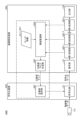
- FIG. 1 is a diagram showing an example of the system configuration of an image processing system.
- FIG. 2 is a diagram illustrating an example of a hardware configuration of an encoding device and an image analysis device;
- FIG. 3 is a diagram showing a specific example of compression rate control processing.
- FIG. 4 is a first flowchart showing the flow of compression rate control processing.
- FIG. 5A is a first diagram showing an example of a compression ratio control result.
- FIG. 5B is a second diagram illustrating an example of a compression ratio control result.
- FIG. 6 is a diagram showing an example of the system configuration of the image processing system in a specific phase.
- FIG. 7 is a diagram illustrating an example of a result of processing by each processing unit;
- FIG. 8 is a diagram showing an example of rule information.
- FIG. 1 is a diagram showing an example of the system configuration of an image processing system.
- FIG. 2 is a diagram illustrating an example of a hardware configuration of an encoding device and an image analysis device
- FIG. 9 is a flowchart showing the flow of rule information generation processing.
- FIG. 10 is a diagram showing an example of the system configuration of the image processing system in the encoding phase.
- FIG. 11 is a second flowchart showing the flow of compression rate control processing.
- FIG. 12 is a diagram illustrating an example of a result of switching compression ratios.
- FIG. 1 is a diagram showing an example of the system configuration of an image processing system.
- the image processing system 100 has an imaging device 110, an encoding device 120, and an image analysis device .
- the encoding device 120 and the image analysis device 130 are communicably connected via a network (not shown).
- the image capture device 110 captures images in a predetermined frame cycle and transmits moving image data to the encoding device 120 .
- An encoding program is installed in the encoding device 120, and the encoding device 120 functions as an encoding unit 121 and a compression rate setting unit 122 by executing the encoding program.
- the encoding unit 121 encodes image data of each frame included in moving image data to generate encoded data.
- the encoding unit 121 uses the compression rate map set by the compression rate setting unit 122 (indicating the compression rate of each region when image data is encoded at a different compression rate for each region). map) to encode the image data.
- the encoding unit 121 also transmits the generated encoded data to the image analysis device 130 .
- the compression rate setting unit 122 sets the acquired compression rate map in the encoding unit 121 each time the compression rate map generated by the image analysis device 130 is acquired. As a result, the compression rate of each region is appropriately controlled when the encoding unit 121 encodes the image data.
- An image analysis program is installed in the image analysis device 130.
- the image analysis device 130 functions as a decoding unit 131, processing units 132_1 to 132_n, an output unit 133, an accuracy monitoring unit 134, and a compression rate map generation unit 135 by executing the image analysis program.
- the decoding unit 131 decodes the encoded data transmitted from the encoding device 120 and generates decoded data.
- the processing units 132_1 to 132_n each perform AI processing on the decoded data in parallel.
- the n types of processing (where n is an integer of 2 or more) by AI include, for example, processing for identifying attributes of each of n types of different objects included in the decrypted data (for example, processing for identifying pedestrian attributes, vehicle , etc.) may be included.
- the output unit 133 outputs the results of processing performed on the decoded data by the processing units 132_1 to 132_n.
- the accuracy monitoring unit 134 performs accuracy monitoring processing based on the rule information 136. It is assumed that the rule information 136 defines rules for determining the compression rate when each of the processing units 132_1 to 132_n performs AI processing on decoded data in parallel. Specifically, in the case of this embodiment, the rule information 136 prescribes "determine the compression ratio so that any processing by AI can obtain a result with a predetermined accuracy or higher". do.
- the accuracy monitoring unit 134 monitors whether or not a predetermined accuracy is obtained for the results of processing performed on the decoded data by the processing units 132_1 to 132_n. Further, when the accuracy monitoring unit 134 determines that the predetermined accuracy is not obtained for the result of any of the processing by the processing units 132_1 to 132_n, the accuracy monitoring unit 134 determines a new compression ratio so as to obtain the predetermined accuracy. do.
- the compression rate map generation section 135 When a new compression rate is determined by the accuracy monitoring section 134, the compression rate map generation section 135 generates a compression rate map based on the determined new compression rate. In this embodiment, the compression rate map generation unit 135 generates a compression rate map in which the determined new compression rate is stored in the entire area of the image data. The compression rate map generation unit 135 generates a compression rate map each time a new compression rate is determined, and transmits the generated compression rate map to the encoding device 120 .
- each unit surrounded by a dashed line indicates that each region is Compression rate control processing is executed to appropriately control the compression rate.
- FIG. 2 is a diagram illustrating an example of a hardware configuration of an encoding device and an image analysis device
- 2a of FIG. 2 is a diagram showing an example of the hardware configuration of the encoding device.
- the encoding device 120 has a processor 201 , a memory 202 , an auxiliary storage device 203 , an I/F (Interface) device 204 , a communication device 205 and a drive device 206 .
- Each piece of hardware of the encoding device 120 is interconnected via a bus 207 .
- the processor 201 has various computing devices such as a CPU (Central Processing Unit) and a GPU (Graphics Processing Unit).
- the processor 201 reads various programs (for example, an encoding program, etc.) onto the memory 202 and executes them.
- the memory 202 has main storage devices such as ROM (Read Only Memory) and RAM (Random Access Memory).
- the processor 201 and the memory 202 form a so-called computer, and the processor 201 executes various programs read onto the memory 202, thereby realizing various functions of the computer.
- the auxiliary storage device 203 stores various programs and various data used when the various programs are executed by the processor 201 .
- the I/F device 204 is a connection device that connects the imaging device 110, which is an example of an external device, and the encoding device 120.
- the communication device 205 is a communication device for communicating with the image analysis device 130 via a network.
- a drive device 206 is a device for setting a recording medium 210 .
- the recording medium 210 here includes media such as CD-ROMs, flexible disks, magneto-optical disks, etc. that record information optically, electrically, or magnetically.
- the recording medium 210 may also include a semiconductor memory or the like that electrically records information, such as a ROM or a flash memory.
- auxiliary storage device 203 Various programs to be installed in the auxiliary storage device 203 are installed by, for example, setting the distributed recording medium 210 in the drive device 206 and reading the various programs recorded in the recording medium 210 by the drive device 206. be done. Alternatively, various programs installed in the auxiliary storage device 203 may be installed by being downloaded from the network via the communication device 205 .
- 2b of FIG. 2 is a diagram showing an example of the hardware configuration of the image analysis device 130.
- the processor 22 for example, reads an image analysis program or the like onto the memory 222 and executes it.
- the I/F device 224 receives operations for the image analysis device 130 via the operation device 231 . Also, the I/F device 224 outputs the result of processing by the image analysis device 130 and displays it via the display device 232 . Also, the communication device 225 communicates with the encoding device 120 via a network.
- FIG. 3 is a diagram showing a specific example of compression rate control processing. Note that in the example of FIG. 3, there are two processing units (processing unit 132_1 and processing unit 132_2) for simplification of explanation.
- reference numeral 310 indicates image data of each frame included in moving image data.
- the example of FIG. 3 shows that the situation around the shooting position changed from "scene A” to "scene B" with the passage of time.
- reference numeral 320 indicates the compression rate of the entire area at each time, with the horizontal axis indicating time and the vertical axis indicating compression rate.
- the compression rate map generation unit 135 generates two compression rate maps including new compression rates in response to changes in the surroundings of the imaging position.
- reference numeral 330 indicates the accuracy of the result of processing performed on the decoded data by the processing unit 132_1, with the horizontal axis indicating time and the vertical axis indicating accuracy. Also, the dotted line indicates the allowable accuracy.
- the result of processing by the processing unit 132_1 was above the allowable accuracy at time t1 , but the situation around the shooting position changed from "scene A" to "scene B.” At later time t2 , the accuracy is less than the allowable accuracy. Further, the result of processing by the processing unit 132_1 greatly exceeds the allowable accuracy at time t3 after the compression rate map including the new compression rate is set for the first time. Furthermore, the result of processing by the processing unit 132_1 approaches the allowable accuracy at time t4 after the compression rate map including the new compression rate is set for the second time.
- reference numeral 340 indicates the accuracy of the result of processing by the processing unit 132_2 performed on the decoded data, with the horizontal axis indicating time and the vertical axis indicating accuracy. Also, the dotted line indicates the allowable accuracy.
- the result of the processing by the processing unit 132_2 was above the allowable accuracy at time t1 and time t2 , but the situation around the shooting position changed from "scene A" to "scene Between time t2 and time t3 after the change to B", the accuracy is approaching acceptable accuracy. Further, the result of processing by the processing unit 132_2 greatly exceeds the allowable accuracy at time t3 after the compression rate map including the new compression rate is set for the first time. Furthermore, the result of processing by the processing unit 132_1 approaches the allowable accuracy at time t4 after the compression rate map including the new compression rate is set for the second time.
- the compression ratio control processing will be described with reference to reference numerals 310, 330, and 340. While “Scene A" continues, the encoding unit 121 is set to the default compression rate, and the result of processing by the processing unit 132_1 and the result of processing by the processing unit 132_2 both exceed the allowable accuracy. ing.
- the accuracy monitoring unit 134 sets a compression ratio lower than the current compression ratio as a new compression ratio, as indicated by reference numeral 320. decide. Further, the compression rate map generation unit 135 generates a compression rate map storing the determined new compression rate in the entire area of the image data, and the compression rate setting unit 122 encodes the generated compression rate map. 121 is set. As a result, the image quality of the decoded data is improved, and both the result of processing by the processing unit 132_1 and the result of processing by the processing unit 132_2 greatly exceed the allowable accuracy.
- the result of the processing by the processing units 132_1 and 132_2 greatly exceeds the allowable accuracy.
- the compression ratio is determined as a new compression ratio.
- the compression rate map generation unit 135 generates a compression rate map storing the determined new compression rate in the entire area of the image data, and the compression rate setting unit 122 encodes the generated compression rate map. 121 is set.
- any AI processing result can be obtained with a predetermined accuracy. That is, according to the present embodiment, it is possible to generate decoded data that can be used in multiple processes by AI.
- the method of calculating the accuracy of the results of processing by each processing unit is arbitrary.
- the processing unit performs a process of identifying an attribute of an object
- the accuracy of the identified attribute or the transition of the accuracy may be calculated as the accuracy of the result of the process.
- the processing unit when the processing unit performs a process of detecting an object, for example, the detection frequency of the object in a plurality of decoded data or the transition of the detection frequency may be calculated as the accuracy of the processing result. .
- the processing unit performs the process of measuring the distance to the object, for example, the fluctuation of the distance to the object in each of the plurality of decoded data or the transition of the fluctuation is used as the accuracy of the processing result. can be calculated.
- the accuracy monitoring unit 134 monitors the accuracy of the results of processing by the processing units 132_1 and 132_2 for the entire area of the image data. Further, the compression rate map generation unit 135 generated a compression rate map by storing the determined new compression rate in the entire area of the image data.
- the compression rate map generation method is not limited to this.
- the accuracy monitoring unit 134 monitors the results of processing by the processing units 132_1 and 132_2 for each compression rate setting granularity (for example, an encoding block in video encoding) that can be set by the encoding unit 121. may be monitored for accuracy.
- the compression rate map generation unit 135 can generate a compression rate map that stores the compression rate determined for each set granularity.
- a compression rate map is generated in which the compression rate determined based on the respective accuracies of the results of processing by the processing units 132_1 and 132_2 is stored in each region for each set granularity in the image data. It will be.
- the position information of objects whose attributes are identified by the processing units 132_1, 132_2, . etc. is effective.
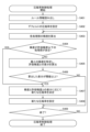
- FIG. 4 is a first flowchart showing the flow of compression rate control processing.
- step S401 the accuracy monitoring unit 134 reads the predefined rule information 136.
- step S402 the compression rate map generation unit 135 generates a compression rate map in which the default compression rate is stored in the entire area of the image data, and the compression rate setting unit 122 encodes the generated compression rate map. 121 is set.
- step S403 the accuracy monitoring unit 134 acquires the results of processing by the processing units 132_1 to 132_n and calculates the accuracy of each processing result.
- step S404 the accuracy monitoring unit 134 determines whether or not there is a processing unit whose processing result is equal to or less than the allowable accuracy. If it is determined in step S404 that there is a processing unit whose processing result is equal to or less than the allowable accuracy (if YES in step S404), the process proceeds to step S407.
- step S407 the accuracy monitoring unit 134 adjusts the accuracy and A new compression ratio is determined according to the difference from the allowable accuracy.
- step S404 determines whether there is no processing unit whose processing result is equal to or less than the allowable accuracy (NO in step S404). If it is determined in step S404 that there is no processing unit whose processing result is equal to or less than the allowable accuracy (NO in step S404), the process proceeds to step S405.
- step S405 the accuracy monitoring unit 134 identifies the minimum accuracy among the accuracies of the results of processing by the processing units 132_1 to 132_n, and calculates the difference between the identified minimum accuracy and the allowable accuracy. .
- step S406 the accuracy monitoring unit 134 determines whether or not the calculated difference is equal to or greater than a predetermined threshold (that is, whether or not the specified minimum accuracy exceeds the allowable accuracy by a predetermined threshold or more). If it is determined in step S406 that it is less than the predetermined threshold value (NO in step S406), the process proceeds to step S409.
- a predetermined threshold that is, whether or not the specified minimum accuracy exceeds the allowable accuracy by a predetermined threshold or more. If it is determined in step S406 that it is less than the predetermined threshold value (NO in step S406), the process proceeds to step S409.
- step S406 determines whether it is equal to or greater than the predetermined threshold (if YES in step S406). If it is determined in step S406 that it is equal to or greater than the predetermined threshold (if YES in step S406), the process proceeds to step S407.
- step S407 the accuracy monitoring unit 134 determines a new compression ratio according to the difference between the minimum accuracy and the allowable accuracy so that the minimum accuracy approaches the allowable accuracy.
- step S408 the compression rate map generation unit 135 generates a compression rate map in which the determined new compression rate is stored in the entire area of the image data, and the compression rate setting unit 122 stores the generated compression rate map. is set in the encoding unit 121 .
- step S409 the accuracy monitoring unit 134 determines whether or not to end the compression rate control process. If it is determined in step S409 to continue the compression rate control process (NO in step S409), the process returns to step S403.
- step S409 if it is determined in step S409 that the compression rate control process should end (if YES in step S409), the compression rate control process ends.
- FIG. 5A is a first diagram showing an example of a compression ratio control result.
- decoded data 510 to 513 represent decoded data processed by the processing unit 132_1 at times t 1 to t 4 in FIG. 3, respectively.
- decoded data 520 to 523 indicate decoded data processed by the processing unit 132_2 at times t 1 to t 4 in FIG. 3, respectively.
- the difference in hatching density indicates the difference in image quality of the decoded data due to the difference in compression rate. Specifically, the lighter the hatching, the lower the compression rate and the higher the image quality of the decoded data, and the darker the hatching, the higher the compression rate and the lower the image quality of the decoded data.
- FIG. 5A shows that the processing unit 132_1 and the processing unit 132_2 were able to identify the attribute of the target object ⁇ and the processing unit 132_2, respectively, at time t1 before the situation around the shooting position changed. ing.
- FIG. 5A shows that the processing unit 132_1 cannot identify the attribute of the target object ⁇ at time t2 due to a change in the circumstances around the imaging position.
- the compression rate is appropriately controlled in response to the inability of the processing unit 132_1 to identify the attribute of the target object ⁇ . This indicates that the processing unit 132_1 has become able to identify the attribute of the target object ⁇ .
- FIG. 5B is a second diagram showing an example of the compression ratio control result.
- the example of FIG. 5B shows a case where accuracy is monitored for each set granularity of the compression rate.
- accuracy is monitored in each of two regions.
- the processing unit 132_1 identifies only the attribute of the object ⁇ positioned below by processing the decoded data 531 by the processing unit 132_1. Further, the processing unit 132_2 identifies both the attribute of the object ⁇ located below and the attribute of the object ⁇ located above by processing the decoded data 541 by the processing unit 132_2.
- the processing unit 132_1 processes the decoded data 532 after the compression ratio of the upper region is appropriately controlled, so that the processing unit 132_1 determines the attribute of the object ⁇ positioned below and the This indicates that both attributes of the object ⁇ located at are successfully identified.
- the processing unit 132_2 processes the decoded data 542 after the compression rate of the upper region has been appropriately controlled, so that the processing unit 132_2 determines the attributes of the object ⁇ located below. and the attributes of the object ⁇ positioned above have been identified.
- the image processing system 100 monitors the accuracy of the results of multiple processing by AI, and appropriately controls the compression rate of each region according to the monitored accuracy.
- the image processing system 100 according to the first embodiment even if the image quality of the decoded data deteriorates due to a change in the situation around the shooting position, the image quality can be improved by changing the compression rate.
- the result of processing by any AI will be able to obtain acceptable accuracy.
- each process eg, x+1th process
- the image processing system according to the second embodiment is equipped with a function for sequentially switching the compression rate.
- a specific phase for identifying a switching method when sequentially switching compression ratios An encoding phase in which the compression rate is sequentially switched and encoded according to the specified switching method; to run.
- the second embodiment will be described below by dividing into a specific phase and an encoding phase. However, the description will focus on the differences from the first embodiment.
- FIG. 6 is a diagram showing an example of the system configuration of the image processing system in a specific phase.
- an image processing system 600 in a specific phase has an encoding device 620 and an image analysis device 630 .
- An encoding program is installed in the encoding device 620, and the encoding device 620 functions as the encoding unit 121 and the compression rate setting unit 622 by executing the encoding program.
- the encoding unit 121 has the same function as the encoding unit 121 described using FIG. 1 in the first embodiment, so the description is omitted here. However, in the identification phase, the encoding unit 121 encodes the image data of each frame included in the identification moving image data to generate encoded data.
- the compression rate setting unit 622 sets the acquired compression rate map in the encoding unit 121 each time the compression rate map generated by the image analysis device 630 is acquired. In the specific phase, the compression rate setting unit 622 creates a compression rate map in which the compression rate is lowered step by step in order to search for a compression rate that can provide the image quality required by each of the plurality of AI processes. Set to 121.
- An image analysis program is installed in the image analysis device 630.
- the image analysis device 630 functions as the decoding unit 131, the first processing unit 632_1, the second processing unit 632_2, . . .
- the image analysis device 630 also functions as a processing result analysis unit 634 , a compression ratio map generation unit 635 and a rule information generation unit 636 .
- decoding unit 131 and the output unit 133 have already been explained using FIG. 1 in the first embodiment, so explanations thereof are omitted here.
- a processing unit that sequentially performs processing by AI is, for example, -
- the first processing unit 632_1 performs an object detection process for detecting a predetermined object from the decoded data, Performing distance measurement processing for measuring the distance to the detected object by the second processing unit 632_2, -Perform a situation judgment process for judging the situation of the object based on the distance measured by the third processing unit 632_3; Refers to the processing unit, etc.
- the first processing unit 632_1, the second processing unit 632_2, . Process each decoded data generated by decoding.
- first processing unit 632_1 the second processing unit 632_2, .
- the processing result analysis unit 634 acquires the result of processing performed on each decoded data from each of the first processing unit 632_1, the second processing unit 632_2, . In addition, the processing result analysis unit 634 analyzes the acquired processing results in the specific phase, and provides the image quality necessary for each processing unit to output the appropriate processing result. Search ratios to identify switching compression ratios.
- the compression rate map generation unit 635 sequentially generates a compression rate map in which the stepwise lowered compression rate is stored in all areas in the specific phase, and transmits the compression rate map to the encoding device 620 .
- the rule information generation unit 636 identifies a switching condition for switching the compression ratio and a switching area based on the switching compression ratio of each processing unit searched by the processing result analysis unit 634 . Then, the rule information generating unit 636 generates rule information defining rules for determining the compression rate when AI processing is sequentially performed on the decoded data.
- ⁇ Conditions for switching the compression rate ⁇ A region where the compression rate is switched when the condition is satisfied, ⁇ When the condition is satisfied, the switching compression rate (switching compression rate), contains decision rules that specify
- each part surrounded by a dashed line performs rule information generation processing for generating rule information.
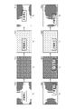
- FIG. 7 is a diagram illustrating an example of a result of processing by each processing unit
- decoded data 710 to 730 represent decoded data generated by encoding and decoding the image data of each frame included in the moving image data for identification by gradually decreasing the compression rate.
- decoded data 710 indicates decoded data in which an object is detected by the object detection processing by the first processing unit 632_1.
- Decoded data 720 indicates decoded data in which the object is detected by the first processing unit 632_1 and the distance to the object is measured by distance measurement processing by the second processing unit 632_2.
- the decoded data 730 the object is detected by the first processing unit 632_1, the distance to the object is measured by the second processing unit 632_2, and the situation of the object is judged by the situation judgment processing by the third processing unit 632_3. Decrypted data is shown.
- the first processing unit 632_1 can appropriately detect the object from the decoded data 710.
- the processing result analysis unit 634 can specify a compression ratio of 1 as the switching compression ratio of the first processing unit 632_1.
- the second processing unit 632_2 appropriately measures the distance to the object in the area where the object is detected in the decoded data 720. be able to.
- the processing result analysis unit 634 can specify the compression ratio of 2 as the switching compression ratio of the second processing unit 632_2.
- the third processing unit 632_3 detects the target object in the decoded data 730 based on the distance to the target object. Appropriately judge the situation of things. Thereby, the processing result analysis unit 634 can specify the compression ratio of 3 as the switching compression ratio of the third processing unit 632_3.
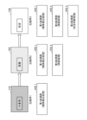
- FIG. 8 is a diagram showing an example of rule information. Also here, for the sake of simplification of explanation, the case where the image analysis device 130 has the first processing section 632_1 to the third processing section 632_3 will be explained.
- the code 810 is The image quality required when the first processing unit 632_1 performs processing, The image quality required when the second processing unit 632_2 performs processing, The image quality required when the third processing unit 632_3 performs processing, are different from each other and (Image quality required for processing by the first processing unit 632_1) ⁇ (Image quality required for processing by the second processing unit 632_2) ⁇ (Required for processing by the third processing unit 632_3 image quality) and the switching compression rate is ⁇ Compression rate 1>Compression rate 2>Compression rate 3 It indicates that it has been identified as
- a compression ratio of 1 is set for the entire area of image data as a default; Switching the compression ratio of the area corresponding to the result of the processing by the first processing unit in the image data to the compression ratio of 2 on the condition that the result of the processing by the first processing unit 632_1 is output; switching the compression ratio of the area corresponding to the result of processing by the second processing unit in the image data to compression ratio 3 on condition that the result of the processing by the second processing unit 632_2 is output; will contain a decision rule that specifies
- symbol 820 is The image quality required when the first processing unit 632_1 performs processing, The image quality required when the second processing unit 632_2 performs processing, The image quality required when the third processing unit 632_3 performs processing, are different from each other and (Image quality required for processing by the first processing unit 632_1) ⁇ (Image quality required for processing by the second processing unit 632_2)> (Required for processing by the third processing unit 632_3 image quality) and the switching compression rate is ⁇ Compression ratio 4>Compression ratio 5 ⁇ Compression ratio 6 It indicates that it has been identified as
- the rule information 821 includes, in addition to the decision rules defined in the rule information 136 described in the first embodiment, - A compression rate of 4 is set for the entire area of the image data as a default; Switching the compression ratio of the area corresponding to the result of the processing by the first processing unit in the image data to the compression ratio of 5 on the condition that the result of the processing by the first processing unit 632_1 is output; will contain a decision rule that specifies
- symbol 830 is The image quality required when the first processing unit 632_1 performs processing, The image quality required when the second processing unit 632_2 performs processing, The image quality required when the third processing unit 632_3 performs processing, are different from each other and (Image quality required for processing by the first processing unit 632_1)>(Image quality required for processing by the second processing unit 632_2)>(Required for processing by the third processing unit 632_3 image quality) and the switching compression rate is ⁇ Compression ratio 7 ⁇ compression ratio 8 ⁇ compression ratio 9 It indicates that it has been identified as
- the rule information 831 includes, in addition to the decision rules defined in the rule information 136 described in the first embodiment, - A compression rate of 7 is set for the entire area of the image data as a default; will contain a decision rule that specifies
- FIG. 9 is a flowchart showing the flow of rule information generation processing.
- step S901 the encoding device 120 acquires moving image data for identification.
- step S902 the processing result analysis unit 634 of the image analysis device 630 sets "1" to a counter m indicating the processing order of each processing unit.
- step S903 the compression rate map generation unit 635 of the image analysis device 630 transmits to the encoding device 120 a compression rate map in which a predetermined compression rate is stored in the entire area of the image data. Also, the compression rate setting unit 622 of the encoding device 120 sets the compression rate map in the encoding unit 121 .
- step S ⁇ b>904 the encoding unit 121 of the encoding device 120 generates encoded data by encoding image data included in the moving image data for identification using the set compression rate map. 130.
- step S905 the decoding unit 131 of the image analysis device 130 decodes the encoded data to generate decoded data.
- step S906 the first to m-th processing units of the image analysis device 130 process the decoded data.
- step S907 the processing result analysis unit 634 of the image analysis device 130 determines whether or not the m-th processing unit has output an appropriate processing result. If it is determined in step S907 that an appropriate result of processing has not been output (NO in step S907), the process proceeds to step S908.
- step S ⁇ b>908 the compression rate map generation unit 635 of the image analysis device 130 generates a compression rate map that stores the compression rate reduced by a predetermined step size for the entire area of the image data, and transmits the compression rate map to the encoding device 120 .
- the compression rate setting unit 622 of the encoding device 120 sets the compression rate map in the encoding unit 121 . After that, the process returns to step S904.
- step S907 determines whether an appropriate result of processing has been output (if YES in step S907). If it is determined in step S907 that an appropriate result of processing has been output (if YES in step S907), the process proceeds to step S909.
- step S909 the processing result analysis unit 634 of the image analysis device 130 specifies the compression ratio when the appropriate processing result is output as the switching compression ratio of the m-th processing unit.
- step S910 the processing result analysis unit 634 of the image analysis device 130 determines whether switching compression ratios have been identified for all processing units. If it is determined in step S910 that there is a processing unit that has not specified the switching compression rate (NO in step S910), the process proceeds to step S911.
- step S911 the processing result analysis unit 634 of the image analysis device 630 increments the counter m indicating the processing order, and returns to step S903.
- step S910 determines whether the switching compression ratio has been specified for all processing units (if YES in step S910). If it is determined in step S910 that the switching compression ratio has been specified for all processing units (if YES in step S910), the process proceeds to step S912.
- step S912 the rule information generation unit 636 of the image analysis device 630 generates rule information based on the switching compression rate of each processing unit, and ends the rule information generation process.
- FIG. 10 is a diagram showing an example of the system configuration of the image processing system in the encoding phase.
- the image processing system 1000 has an imaging device 110 , an encoding device 620 and an image analysis device 630 .
- An encoding program is installed in the encoding device 620, and the encoding device 620 functions as the encoding unit 121 and the compression rate setting unit 622 by executing the encoding program.
- the encoding unit 121 has the same function as the encoding unit 121 described using FIG. 1 in the first embodiment, so the description is omitted here.
- the compression rate setting unit 622 sets the acquired compression rate map in the encoding unit 121 each time the compression rate map generated by the image analysis device 630 is acquired. Note that in the encoding phase, the compression rate setting unit 622 - A compression ratio map in which a switching compression ratio based on rule information (for example, any of the rule information 811 to 831) is stored in each area, or - A compression ratio map in which a compression ratio newly determined for the switching compression ratio is stored in each area; to get one of
- An image analysis program is installed in the image analysis device 630.
- the image analysis device 630 includes the decoding unit 131, the first processing unit 632_1, the second processing unit 632_2, . , functions as a compression rate map generator 635 .
- Accuracy monitoring unit 1034 performs accuracy monitoring processing based on rule information (for example, any of rule information 811 to 831).
- rule information for example, any of rule information 811 to 831.
- the accuracy monitoring unit 1034 monitors whether or not a predetermined accuracy is obtained for the results of processing by each processing unit. Then, if the accuracy monitoring unit 134 determines that the predetermined accuracy is not obtained for the result of processing by any of the processing units, it determines a new compression rate so that the predetermined accuracy is obtained.
- the compression ratio map generating unit 635 When the accuracy monitoring unit 1034 notifies the compression ratio map generation unit 635 of the switching compression ratio, the compression ratio map generating unit 635 generates a compression ratio map by storing the switching compression ratio in the corresponding area. In addition, when the accuracy monitoring unit 1034 notifies the compression ratio map generation unit 635 of the newly determined compression ratio, the compression ratio map generation unit 635 generates the compression ratio map by storing the newly determined compression ratio in the corresponding area. Generate. Also, the compression rate map generator 635 transmits the generated compression rate map to the encoding device 620 each time it generates a compression rate map.
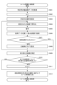
- FIG. 11 is a second flowchart showing the flow of compression rate control processing.
- steps S1101 to S1103 and step S1104 are different from the compression rate control process described with reference to FIG.
- step S1101 the accuracy monitoring unit 1034 determines whether or not the results of processing by the first processing unit 632_1 to n-th processing unit 632_n satisfy the switching conditions specified in the rule information.
- step S1101 If it is determined in step S1101 that the switching condition is not satisfied (NO in step S1101), the process proceeds to step S1103.
- step S1101 determines whether the switching condition is satisfied (if YES in step S1101), the process proceeds to step S1102.
- step S1102 the compression rate map generation unit 635 generates a compression rate map by storing the switched compression rate in the corresponding area. Also, the compression rate setting unit 622 sets the generated compression rate map in the encoding unit 121 .
- step S1103 the accuracy monitoring unit 1034 acquires the results of processing by the first processing unit 632_1 to n-th processing unit 632_n, and calculates the accuracy of each processing result.
- step S1104 compression rate map generation section 635 generates a compression rate map by storing the newly determined compression rate in the corresponding area, and compression rate setting section 622 stores the generated compression rate map. It is set in the encoding unit 121 .
- FIG. 12 is a diagram illustrating an example of a result of switching compression ratios.
- decoded data 1210 to 1240 represent decoded data generated by encoding and decoding image data of each frame included in moving image data.
- the difference in hatching density indicates the difference in image quality of the decoded data due to the difference in compression rate. Specifically, the lighter the hatching, the lower the compression rate and the higher the image quality of the decoded data, and the darker the hatching, the higher the compression rate and the lower the image quality of the decoded data.
- FIG. 12 shows how multiple objects appear over time.
- the first processing unit 632_1 performs object detection processing on the entire region of the decoded data.
- the image data is encoded at a compression rate of 1.
- the first processing unit 632_1 performs object detection processing on the entire area and detects the target object 1201. At this time, the image data is encoded at a compression rate of 1, but as the object 1201 is detected, the compression rate of the area corresponding to the area where the object 1201 is detected is lower than the compression rate of 1. is switched to a lower compression ratio of 2.
- the decoded data 1230 is the image data, - the region corresponding to the region where the object 1201 is detected is encoded at a compression rate of 2, and ⁇ A region other than the region corresponding to the region where the target object 1201 is detected is encoded at a compression rate of 1. This is decoded data generated by decoding encoded data.
- the first processing unit 632_1 performs object detection processing on the entire area, and detects the target objects 1201 and 1211. Further, the second processing unit 632_2 performs distance measurement processing on the area where the object 1201 is detected, and measures the distance to the object. Also, as the distance measurement process is performed on the object 1201, the compression ratio of the area corresponding to the area where the object 1201 is detected is switched to compression ratio 3, which is lower than compression ratio 2. FIG. Further, as the object 1211 is newly detected, the compression ratio of the area corresponding to the area where the object 1211 is detected is switched to compression ratio 2, which is lower than compression ratio 1. FIG.
- the decoded data 1240 is the image data, - the region corresponding to the region where the object 1201 is detected is encoded at a compression rate of 3, and - the region corresponding to the region where the object 1211 is detected is encoded at a compression rate of 2, and ⁇ A region other than the region corresponding to the region where the object 1201 and the object 1211 are detected is encoded at a compression rate of 1.
- This is decoded data generated by decoding encoded data.
- the first processing unit 632_1 performs object detection processing on the entire area, and detects the target objects 1201, 1211, and 1221.
- the second processing unit 632_2 performs distance measurement processing on the area where the target object 1201 is detected, and after measuring the distance to the target object, the third processing unit 632_3 performs situation determination processing, Determine the status of objects.
- the second processing unit 632_2 performs distance measurement processing on the area where the object 1211 is detected, and measures the distance to the object. Also, as the distance measurement process is performed on the object 1211, the compression ratio of the area corresponding to the area where the object 1211 is detected is switched to the compression ratio 3, which is lower than the compression ratio 2.
- the compression ratio of the area corresponding to the area where the object 1221 is detected is switched to compression ratio 2, which is lower than compression ratio 1.
- the new compression ratio 1 may be determined by, for example, detecting the object 1201 in the decoded data 1220 and then calculating the accuracy of the result of processing by the first processing unit 632_1.
- the new compression rate of 2 is determined by, for example, performing distance measurement processing on the object 1201 in the decoded data 1230 and then calculating the accuracy of the result of processing by the second processing unit 632_2. good too.
- the new compression rate of 3 is determined by, for example, calculating the accuracy of the result of processing by the third processing unit 632_3 after performing the situation determination processing on the object 1201 in the decoded data 1240. good too.
- the image processing system 1000 performs a plurality of AI-based processing on each region of decoded data generated by decoding encoded image data. Processing is done sequentially. Further, the image processing system 1000 according to the second embodiment performs the x-th process when the image quality required for the x+1-th process is higher than the image quality required for the x-th process. Switch the compression rate of the area corresponding to the result of to the switching compression rate.
- each process can be performed appropriately when a plurality of processes are sequentially performed by AI.
- the image processing system 1000 according to the second embodiment compresses each region when encoding image data so that the results of any of the plurality of processings by AI can obtain acceptable accuracy. determine the rate. Also, the image processing system 1000 according to the second embodiment encodes the image data at the determined compression rate for each area.
- the image processing system 1000 monitors the accuracy of the results of multiple processing by AI, and appropriately controls the compression rate after switching each region according to the monitored accuracy.
- the image processing system 1000 according to the second embodiment even if the image quality of the decoded data deteriorates due to a change in the situation around the shooting position, the image quality can be improved by changing the compression rate.
- the result of processing by any AI will be able to obtain acceptable accuracy.
- the encoding devices 120, 620 and the image analysis devices 130, 630 are separate devices, but the encoding devices 120, 620 and the image analysis devices 130, 630 are integrated devices. good too.
- the imaging device 110 and the encoding devices 120 and 620 are separate devices, but the imaging device 110 and the encoding devices 120 and 620 may be an integrated device.
- part of the functions realized by the image analysis devices 130 and 630 may be realized by the encoding devices 120 and 620, and part of the functions realized by the encoding devices 120 and 620 may be implemented by the encoding devices 120 and 620. may be realized by the image analysis device 130, 630.
- the specific phase and the encoding phase are described as using different image processing systems, but the same image processing system may be used to execute the specific phase and the encoding phase. .
- the switching compression rate is specified by stepwise decreasing the compression rate in the specific phase, but the switching compression rate is specified by stepwise increasing the compression rate.
- a new compression rate is determined after switching to the switching compression rate in the encoding phase.
- the new compression rate that has already been determined may be used when switching to the switching compression rate.
- the compression rate is determined for each area in which an object is detected. You may make it
- the method of determining a new compression rate by the precision monitoring unit described in each of the above embodiments is merely an example.
- the compression rate may be determined based on information for determining the compression rate obtained by analyzing the recognition state and recognition process by AI and information indicating the accuracy transition of the processing result. good.
- the compression rate corresponding to the processing unit that performs processing on a predetermined area is determined, the compression rate is increased step by step while observing the accuracy transition of the processing result of the processing unit. (or lower).
- the compression rate may be determined based on information for determining the compression rate, which is obtained by analyzing the processing state and process of a processing unit that processes a predetermined region.
- information for determining the compression ratio obtained by analyzing the processing state and process of a processing unit that performs processing on a predetermined area, and a processing unit different from the processing unit that determines the compression ratio
- the compression ratio may be determined based on the accuracy transition of the processing results.
- recognition processing by AI described in each of the above embodiments may include analysis processing and the like that obtain results based on analysis by a computer or the like, in addition to deep learning processing.
- the compression ratio of the area may be determined based on the results of processing by the part of the processing units.
- the compression ratio of the region may be determined including the result of processing by a processing unit that does not perform processing.
- Image processing system 110 Imaging device 120: Encoding device 121: Encoding unit 122: Compression rate setting unit 130: Image analysis device 131: Decoding unit 132_1 to 132_n: Processing unit 133: Output unit 134: Accuracy monitoring unit 135 : Compression rate map generation unit 136 : Rule information 620 : Encoding device 622 : Compression rate setting unit 632_1 : First processing unit 632_2 : Second processing unit 632_3 : Third processing unit 632_n : nth processing unit 634 : Processing result analysis Unit 635: Compression rate map generation unit 636: Rule information generation unit 811 to 831: Rule information 1034: Accuracy monitoring unit
Landscapes
- Engineering & Computer Science (AREA)
- Physics & Mathematics (AREA)
- General Physics & Mathematics (AREA)
- Theoretical Computer Science (AREA)
- Multimedia (AREA)
- Signal Processing (AREA)
- Compression Or Coding Systems Of Tv Signals (AREA)
Priority Applications (3)
| Application Number | Priority Date | Filing Date | Title |
|---|---|---|---|
| JP2023549243A JP7670149B2 (ja) | 2021-09-24 | 2021-09-24 | 画像処理システム、符号化装置、符号化方法及び符号化プログラム |
| PCT/JP2021/035014 WO2023047516A1 (ja) | 2021-09-24 | 2021-09-24 | 画像処理システム、符号化装置、符号化方法及び符号化プログラム |
| US18/444,823 US20240193817A1 (en) | 2021-09-24 | 2024-02-19 | Image processing system, encoding method, and computer-readable recording medium storing encoding program |
Applications Claiming Priority (1)
| Application Number | Priority Date | Filing Date | Title |
|---|---|---|---|
| PCT/JP2021/035014 WO2023047516A1 (ja) | 2021-09-24 | 2021-09-24 | 画像処理システム、符号化装置、符号化方法及び符号化プログラム |
Related Child Applications (1)
| Application Number | Title | Priority Date | Filing Date |
|---|---|---|---|
| US18/444,823 Continuation US20240193817A1 (en) | 2021-09-24 | 2024-02-19 | Image processing system, encoding method, and computer-readable recording medium storing encoding program |
Publications (1)
| Publication Number | Publication Date |
|---|---|
| WO2023047516A1 true WO2023047516A1 (ja) | 2023-03-30 |
Family
ID=85719377
Family Applications (1)
| Application Number | Title | Priority Date | Filing Date |
|---|---|---|---|
| PCT/JP2021/035014 Ceased WO2023047516A1 (ja) | 2021-09-24 | 2021-09-24 | 画像処理システム、符号化装置、符号化方法及び符号化プログラム |
Country Status (3)
| Country | Link |
|---|---|
| US (1) | US20240193817A1 (https=) |
| JP (1) | JP7670149B2 (https=) |
| WO (1) | WO2023047516A1 (https=) |
Citations (3)
| Publication number | Priority date | Publication date | Assignee | Title |
|---|---|---|---|---|
| JP2016025494A (ja) * | 2014-07-22 | 2016-02-08 | ルネサスエレクトロニクス株式会社 | 画像受信装置、画像伝送システムおよび画像受信方法 |
| JP2017211799A (ja) * | 2016-05-25 | 2017-11-30 | キヤノン株式会社 | 情報処理装置および情報処理方法 |
| WO2021152849A1 (ja) * | 2020-01-31 | 2021-08-05 | 富士通株式会社 | データ処理装置及びデータ処理プログラム |
Family Cites Families (2)
| Publication number | Priority date | Publication date | Assignee | Title |
|---|---|---|---|---|
| US11221990B2 (en) * | 2015-04-03 | 2022-01-11 | The Mitre Corporation | Ultra-high compression of images based on deep learning |
| JP6658191B2 (ja) * | 2016-03-25 | 2020-03-04 | 富士通株式会社 | 符号化装置、符号化方法、及びプログラム |
-
2021
- 2021-09-24 JP JP2023549243A patent/JP7670149B2/ja active Active
- 2021-09-24 WO PCT/JP2021/035014 patent/WO2023047516A1/ja not_active Ceased
-
2024
- 2024-02-19 US US18/444,823 patent/US20240193817A1/en active Pending
Patent Citations (3)
| Publication number | Priority date | Publication date | Assignee | Title |
|---|---|---|---|---|
| JP2016025494A (ja) * | 2014-07-22 | 2016-02-08 | ルネサスエレクトロニクス株式会社 | 画像受信装置、画像伝送システムおよび画像受信方法 |
| JP2017211799A (ja) * | 2016-05-25 | 2017-11-30 | キヤノン株式会社 | 情報処理装置および情報処理方法 |
| WO2021152849A1 (ja) * | 2020-01-31 | 2021-08-05 | 富士通株式会社 | データ処理装置及びデータ処理プログラム |
Non-Patent Citations (2)
| Title |
|---|
| TOMONORI KUBOTA, TAKANORI NAKAO, EIJI YOSHIDA: "A high-compression video coding method for video analysis using Deep Learning", IEICE TECHNICAL REPORT, IEICE, JP, vol. 119, no. 456 (IE2019-121), 27 February 2020 (2020-02-27), JP , pages 121 - 126, XP009539202, ISSN: 2432-6380 * |
| TOMONORI KUBOTA, TAKANORI NAKAO, MASAFUMI KATOH, EIJI YOSHIDA, HIDENOBU MIYOSHI: "A method for analyze causes of deterioration of predict quality when Deep Learning is applied to instance segmentation", ITE TECHNICAL REPORT, EIZO JOHO MEDIA GAKKAI, TOKYO, JP, vol. 44, no. 12 (BioX2020-14,SIP2020-14,IE2020-14,MI2020-14), 21 May 2020 (2020-05-21), JP , pages 93 - 98, XP009544971, ISSN: 1342-6893 * |
Also Published As
| Publication number | Publication date |
|---|---|
| JP7670149B2 (ja) | 2025-04-30 |
| US20240193817A1 (en) | 2024-06-13 |
| JPWO2023047516A1 (https=) | 2023-03-30 |
Similar Documents
| Publication | Publication Date | Title |
|---|---|---|
| GB2590222A (en) | MVD precision for affine | |
| JP6605581B2 (ja) | ビデオ符号化のための適応検索ウィンドウの配置 | |
| US10742989B2 (en) | Variable frame rate encoding method and device based on a still area or a motion area | |
| JP2022527194A5 (https=) | ||
| CN114898273A (zh) | 一种视频监控异常检测方法、装置及设备 | |
| US10108522B1 (en) | Sampling technique to adjust application sampling rate | |
| US10051281B2 (en) | Video coding system with efficient processing of zooming transitions in video | |
| CN114299074B (zh) | 一种视频分割方法、装置、设备及存储介质 | |
| JP7310148B2 (ja) | メディア符号化方法および装置 | |
| CN113688832B (zh) | 一种模型训练及图像处理方法、装置 | |
| KR20050020714A (ko) | 움직임 벡터 검출 장치 및 움직임 벡터 검출 방법 | |
| KR20220064950A (ko) | 프레임 간 예측 방법 및 장치, 기기, 저장 매체 | |
| CN114283312A (zh) | 一种模型训练方法、装置、存储介质及电子设备 | |
| WO2023047516A1 (ja) | 画像処理システム、符号化装置、符号化方法及び符号化プログラム | |
| US10674174B2 (en) | Coding apparatus, coding method, and recording medium | |
| CN115190309A (zh) | 视频帧处理方法、训练方法、装置、设备及存储介质 | |
| JP7161379B2 (ja) | 推論装置 | |
| JP2001285874A (ja) | 動きベクトル探索装置、方法及びプログラムを記録した記録媒体 | |
| JPH08140098A (ja) | 動き補償符号化装置 | |
| US11398091B1 (en) | Repairing missing frames in recorded video with machine learning | |
| JP2007166545A (ja) | 動きベクトル検出装置及び方法 | |
| JP4430690B2 (ja) | 動き探索装置、動き探索方法、動き探索プログラムおよびそのプログラムを記録したコンピュータ読み取り可能な記録媒体 | |
| EP3806447A1 (en) | Imaging control device, imaging control method, and program | |
| CN119540826B (zh) | 时空行为检测方法 | |
| US12505582B2 (en) | Image compression performance optimization for image compression |
Legal Events
| Date | Code | Title | Description |
|---|---|---|---|
| 121 | Ep: the epo has been informed by wipo that ep was designated in this application |
Ref document number: 21958392 Country of ref document: EP Kind code of ref document: A1 |
|
| WWE | Wipo information: entry into national phase |
Ref document number: 2023549243 Country of ref document: JP |
|
| NENP | Non-entry into the national phase |
Ref country code: DE |
|
| 122 | Ep: pct application non-entry in european phase |
Ref document number: 21958392 Country of ref document: EP Kind code of ref document: A1 |