WO2023042833A1 - Heat-dissipating sheet and method for manufacturing same - Google Patents
Heat-dissipating sheet and method for manufacturing same Download PDFInfo
- Publication number
- WO2023042833A1 WO2023042833A1 PCT/JP2022/034325 JP2022034325W WO2023042833A1 WO 2023042833 A1 WO2023042833 A1 WO 2023042833A1 JP 2022034325 W JP2022034325 W JP 2022034325W WO 2023042833 A1 WO2023042833 A1 WO 2023042833A1
- Authority
- WO
- WIPO (PCT)
- Prior art keywords
- rubber
- elastic body
- sheet
- heat dissipation
- heat
- Prior art date
Links
- 238000004519 manufacturing process Methods 0.000 title claims abstract description 48
- 238000000034 method Methods 0.000 title claims abstract description 46
- 239000011231 conductive filler Substances 0.000 claims abstract description 48
- 230000017525 heat dissipation Effects 0.000 claims description 124
- 229920000049 Carbon (fiber) Polymers 0.000 claims description 91
- 239000004917 carbon fiber Substances 0.000 claims description 91
- 239000000314 lubricant Substances 0.000 claims description 78
- 229920001971 elastomer Polymers 0.000 claims description 63
- 239000005060 rubber Substances 0.000 claims description 63
- 238000005520 cutting process Methods 0.000 claims description 48
- 239000007788 liquid Substances 0.000 claims description 48
- 239000011148 porous material Substances 0.000 claims description 38
- 239000000945 filler Substances 0.000 claims description 37
- 239000000203 mixture Substances 0.000 claims description 25
- 238000000465 moulding Methods 0.000 claims description 24
- 229920002379 silicone rubber Polymers 0.000 claims description 21
- VNWKTOKETHGBQD-UHFFFAOYSA-N methane Chemical group C VNWKTOKETHGBQD-UHFFFAOYSA-N 0.000 claims description 17
- 239000004945 silicone rubber Substances 0.000 claims description 15
- 238000007599 discharging Methods 0.000 claims description 14
- 238000003475 lamination Methods 0.000 claims description 8
- 239000011247 coating layer Substances 0.000 claims description 7
- 239000004944 Liquid Silicone Rubber Substances 0.000 claims description 5
- OKTJSMMVPCPJKN-UHFFFAOYSA-N Carbon Chemical compound [C] OKTJSMMVPCPJKN-UHFFFAOYSA-N 0.000 description 65
- 229910052799 carbon Inorganic materials 0.000 description 65
- 230000004048 modification Effects 0.000 description 47
- 238000012986 modification Methods 0.000 description 47
- 238000001816 cooling Methods 0.000 description 26
- 239000010410 layer Substances 0.000 description 18
- 229920005989 resin Polymers 0.000 description 17
- 239000011347 resin Substances 0.000 description 17
- 238000001723 curing Methods 0.000 description 11
- 239000000463 material Substances 0.000 description 11
- 230000005855 radiation Effects 0.000 description 9
- -1 polyethylene Polymers 0.000 description 6
- 229910052582 BN Inorganic materials 0.000 description 5
- PZNSFCLAULLKQX-UHFFFAOYSA-N Boron nitride Chemical compound N#B PZNSFCLAULLKQX-UHFFFAOYSA-N 0.000 description 5
- 239000011248 coating agent Substances 0.000 description 5
- 238000000576 coating method Methods 0.000 description 5
- 238000011049 filling Methods 0.000 description 5
- XLOMVQKBTHCTTD-UHFFFAOYSA-N Zinc monoxide Chemical compound [Zn]=O XLOMVQKBTHCTTD-UHFFFAOYSA-N 0.000 description 4
- 239000003795 chemical substances by application Substances 0.000 description 4
- 238000010586 diagram Methods 0.000 description 4
- 230000000694 effects Effects 0.000 description 4
- 229920005992 thermoplastic resin Polymers 0.000 description 4
- 229920001187 thermosetting polymer Polymers 0.000 description 4
- 239000000853 adhesive Substances 0.000 description 3
- 230000001070 adhesive effect Effects 0.000 description 3
- 230000006835 compression Effects 0.000 description 3
- 238000007906 compression Methods 0.000 description 3
- 238000005530 etching Methods 0.000 description 3
- 230000003746 surface roughness Effects 0.000 description 3
- PIGFYZPCRLYGLF-UHFFFAOYSA-N Aluminum nitride Chemical compound [Al]#N PIGFYZPCRLYGLF-UHFFFAOYSA-N 0.000 description 2
- 230000001154 acute effect Effects 0.000 description 2
- WNROFYMDJYEPJX-UHFFFAOYSA-K aluminium hydroxide Chemical compound [OH-].[OH-].[OH-].[Al+3] WNROFYMDJYEPJX-UHFFFAOYSA-K 0.000 description 2
- PNEYBMLMFCGWSK-UHFFFAOYSA-N aluminium oxide Inorganic materials [O-2].[O-2].[O-2].[Al+3].[Al+3] PNEYBMLMFCGWSK-UHFFFAOYSA-N 0.000 description 2
- 239000011337 anisotropic pitch Substances 0.000 description 2
- 230000006866 deterioration Effects 0.000 description 2
- 229910003460 diamond Inorganic materials 0.000 description 2
- 239000010432 diamond Substances 0.000 description 2
- 239000013013 elastic material Substances 0.000 description 2
- 239000000835 fiber Substances 0.000 description 2
- 239000004519 grease Substances 0.000 description 2
- 238000010438 heat treatment Methods 0.000 description 2
- TWNQGVIAIRXVLR-UHFFFAOYSA-N oxo(oxoalumanyloxy)alumane Chemical compound O=[Al]O[Al]=O TWNQGVIAIRXVLR-UHFFFAOYSA-N 0.000 description 2
- 229920001084 poly(chloroprene) Polymers 0.000 description 2
- 229920000139 polyethylene terephthalate Polymers 0.000 description 2
- 239000005020 polyethylene terephthalate Substances 0.000 description 2
- 229920005749 polyurethane resin Polymers 0.000 description 2
- HBMJWWWQQXIZIP-UHFFFAOYSA-N silicon carbide Chemical compound [Si+]#[C-] HBMJWWWQQXIZIP-UHFFFAOYSA-N 0.000 description 2
- 229910010271 silicon carbide Inorganic materials 0.000 description 2
- 238000009966 trimming Methods 0.000 description 2
- 239000011787 zinc oxide Substances 0.000 description 2
- 229910018072 Al 2 O 3 Inorganic materials 0.000 description 1
- 229920002799 BoPET Polymers 0.000 description 1
- 229920000181 Ethylene propylene rubber Polymers 0.000 description 1
- 244000043261 Hevea brasiliensis Species 0.000 description 1
- 229920000459 Nitrile rubber Polymers 0.000 description 1
- 239000004952 Polyamide Substances 0.000 description 1
- 239000005062 Polybutadiene Substances 0.000 description 1
- 239000004698 Polyethylene Substances 0.000 description 1
- 239000004734 Polyphenylene sulfide Substances 0.000 description 1
- 229920001328 Polyvinylidene chloride Polymers 0.000 description 1
- 229920006311 Urethane elastomer Polymers 0.000 description 1
- BZHJMEDXRYGGRV-UHFFFAOYSA-N Vinyl chloride Chemical compound ClC=C BZHJMEDXRYGGRV-UHFFFAOYSA-N 0.000 description 1
- 229920000122 acrylonitrile butadiene styrene Polymers 0.000 description 1
- 230000015572 biosynthetic process Effects 0.000 description 1
- 229920005549 butyl rubber Polymers 0.000 description 1
- 239000003054 catalyst Substances 0.000 description 1
- 238000009833 condensation Methods 0.000 description 1
- 230000005494 condensation Effects 0.000 description 1
- PMHQVHHXPFUNSP-UHFFFAOYSA-M copper(1+);methylsulfanylmethane;bromide Chemical compound Br[Cu].CSC PMHQVHHXPFUNSP-UHFFFAOYSA-M 0.000 description 1
- 229910052593 corundum Inorganic materials 0.000 description 1
- 238000010894 electron beam technology Methods 0.000 description 1
- 239000003822 epoxy resin Substances 0.000 description 1
- 239000010696 ester oil Substances 0.000 description 1
- 230000009969 flowable effect Effects 0.000 description 1
- 229920001973 fluoroelastomer Polymers 0.000 description 1
- 230000020169 heat generation Effects 0.000 description 1
- 230000010354 integration Effects 0.000 description 1
- 229920003049 isoprene rubber Polymers 0.000 description 1
- 238000010030 laminating Methods 0.000 description 1
- 230000014759 maintenance of location Effects 0.000 description 1
- 229920003052 natural elastomer Polymers 0.000 description 1
- 229920001194 natural rubber Polymers 0.000 description 1
- 230000000149 penetrating effect Effects 0.000 description 1
- 229920003207 poly(ethylene-2,6-naphthalate) Polymers 0.000 description 1
- 229920002647 polyamide Polymers 0.000 description 1
- 229920002857 polybutadiene Polymers 0.000 description 1
- 229920001707 polybutylene terephthalate Polymers 0.000 description 1
- 229920000515 polycarbonate Polymers 0.000 description 1
- 239000004417 polycarbonate Substances 0.000 description 1
- 229920000647 polyepoxide Polymers 0.000 description 1
- 229920000573 polyethylene Polymers 0.000 description 1
- 239000011112 polyethylene naphthalate Substances 0.000 description 1
- 229920013716 polyethylene resin Polymers 0.000 description 1
- 229920000069 polyphenylene sulfide Polymers 0.000 description 1
- 229920001296 polysiloxane Polymers 0.000 description 1
- 229920000915 polyvinyl chloride Polymers 0.000 description 1
- 239000004800 polyvinyl chloride Substances 0.000 description 1
- 239000005033 polyvinylidene chloride Substances 0.000 description 1
- 239000002243 precursor Substances 0.000 description 1
- 229920002545 silicone oil Polymers 0.000 description 1
- 229920002050 silicone resin Polymers 0.000 description 1
- 239000007787 solid Substances 0.000 description 1
- 229920003048 styrene butadiene rubber Polymers 0.000 description 1
- 229920003051 synthetic elastomer Polymers 0.000 description 1
- 239000005061 synthetic rubber Substances 0.000 description 1
- 229910001845 yogo sapphire Inorganic materials 0.000 description 1
Images


Classifications
-
- B—PERFORMING OPERATIONS; TRANSPORTING
- B29—WORKING OF PLASTICS; WORKING OF SUBSTANCES IN A PLASTIC STATE IN GENERAL
- B29B—PREPARATION OR PRETREATMENT OF THE MATERIAL TO BE SHAPED; MAKING GRANULES OR PREFORMS; RECOVERY OF PLASTICS OR OTHER CONSTITUENTS OF WASTE MATERIAL CONTAINING PLASTICS
- B29B15/00—Pretreatment of the material to be shaped, not covered by groups B29B7/00 - B29B13/00
- B29B15/08—Pretreatment of the material to be shaped, not covered by groups B29B7/00 - B29B13/00 of reinforcements or fillers
-
- C—CHEMISTRY; METALLURGY
- C08—ORGANIC MACROMOLECULAR COMPOUNDS; THEIR PREPARATION OR CHEMICAL WORKING-UP; COMPOSITIONS BASED THEREON
- C08J—WORKING-UP; GENERAL PROCESSES OF COMPOUNDING; AFTER-TREATMENT NOT COVERED BY SUBCLASSES C08B, C08C, C08F, C08G or C08H
- C08J5/00—Manufacture of articles or shaped materials containing macromolecular substances
- C08J5/18—Manufacture of films or sheets
-
- H—ELECTRICITY
- H01—ELECTRIC ELEMENTS
- H01L—SEMICONDUCTOR DEVICES NOT COVERED BY CLASS H10
- H01L23/00—Details of semiconductor or other solid state devices
- H01L23/34—Arrangements for cooling, heating, ventilating or temperature compensation ; Temperature sensing arrangements
- H01L23/36—Selection of materials, or shaping, to facilitate cooling or heating, e.g. heatsinks
- H01L23/373—Cooling facilitated by selection of materials for the device or materials for thermal expansion adaptation, e.g. carbon
-
- H—ELECTRICITY
- H05—ELECTRIC TECHNIQUES NOT OTHERWISE PROVIDED FOR
- H05K—PRINTED CIRCUITS; CASINGS OR CONSTRUCTIONAL DETAILS OF ELECTRIC APPARATUS; MANUFACTURE OF ASSEMBLAGES OF ELECTRICAL COMPONENTS
- H05K7/00—Constructional details common to different types of electric apparatus
- H05K7/20—Modifications to facilitate cooling, ventilating, or heating
-
- Y—GENERAL TAGGING OF NEW TECHNOLOGICAL DEVELOPMENTS; GENERAL TAGGING OF CROSS-SECTIONAL TECHNOLOGIES SPANNING OVER SEVERAL SECTIONS OF THE IPC; TECHNICAL SUBJECTS COVERED BY FORMER USPC CROSS-REFERENCE ART COLLECTIONS [XRACs] AND DIGESTS
- Y02—TECHNOLOGIES OR APPLICATIONS FOR MITIGATION OR ADAPTATION AGAINST CLIMATE CHANGE
- Y02E—REDUCTION OF GREENHOUSE GAS [GHG] EMISSIONS, RELATED TO ENERGY GENERATION, TRANSMISSION OR DISTRIBUTION
- Y02E60/00—Enabling technologies; Technologies with a potential or indirect contribution to GHG emissions mitigation
- Y02E60/10—Energy storage using batteries
Definitions
- the present invention relates to a heat dissipation sheet and its manufacturing method.
- a heat dissipation sheet between a heat source such as a circuit board and a cooling member such as a heat sink or a cooling fan.
- a heat-dissipating sheet a rubber-like elastic material such as resin or rubber in which a thermally conductive filler is dispersed is widely used.
- a heat-dissipating sheet in which carbon fibers as a thermally conductive filler are oriented in the thickness direction of the heat-dissipating sheet (see, for example, Patent Document 1).
- thermal conductivity is required for such a heat dissipation sheet.
- this is dealt with by increasing the filling rate of a thermally conductive filler such as carbon fiber contained in the heat dissipation sheet.
- increasing the filling rate of the thermally conductive filler may increase the hardness of the heat dissipating sheet and impair its flexibility. If the heat-dissipating sheet has a high hardness, there is a possibility that the heat conductivity will decrease due to the deterioration of the adhesion to the heat source and the cooling member.
- the conventionally known heat dissipation sheet as described above is manufactured by slicing a flexible sheet precursor formed so that the carbon fibers are oriented in one direction in the plane along a plane perpendicular to the orientation direction. be. Since the heat dissipating sheet manufactured in this manner has a large surface roughness on the cut surface, the thermal resistance at the contact interface with the heat source and/or the cooling member increases, and the thermal conductivity in the thickness direction of the heat dissipating sheet increases. There is a risk that it will decrease. This applies not only to circuit boards, but also to other heat sources such as electronic components, electronic equipment bodies or battery cells.
- An object of the present invention is to provide a heat dissipating sheet capable of achieving low hardness and high thermal conductivity, and a method for manufacturing the same, in order to solve the above problems.
- a heat dissipation sheet according to an embodiment for achieving the above object, a sheet-like rubber-like elastic body; a long thermally conductive filler that is embedded and oriented in a direction oblique to the thickness direction of the rubber-like elastic body and that has a thermal conductivity superior to that of the rubber-like elastic body;
- a heat dissipation sheet comprising the rubber-like elastic body has at least one pore oriented parallel to the thickness direction of the rubber-like elastic body or oriented obliquely to the thickness direction; Both ends of the thermally conductive filler are exposed on the surface of the rubber-like elastic body.
- the rubber-like elastic body has at least one hole oriented in a direction oblique to the thickness direction of the rubber-like elastic body, Both ends of the conductive filler may be exposed on the surface of the rubber-like elastic body.
- the thermally conductive filler is embedded and oriented at an angle larger than 45° and smaller than 85° with respect to the surface of the rubber-like elastic body. Also good.
- the thermally conductive filler is embedded in the rubber-like elastic body so that the diameter of the both ends exposed on the surface of the rubber-like elastic body is It may be larger than the diameter of the region in which it is located.
- uncured liquid rubber is cured between the rubber-like elastic body and the hole or between the hole and another hole. It may be provided with silicone rubber.
- the uncured liquid rubber may be liquid silicone rubber.
- the rubber-like elastic body may be silicone rubber.
- a heat-dissipating sheet according to another embodiment may preferably have a lubricant coating layer on at least one of the front and back surfaces of the rubber-like elastic body.
- a heat dissipation sheet according to another embodiment may preferably have a lubricant in the pores of the rubber-like elastic body.
- a heat-dissipating sheet according to another embodiment preferably has a lubricant in the pores, and coats at least one of the front and back surfaces of the rubber-like elastic body with the lubricant. It may have layers.
- the pores located on the outermost periphery in the plane of the rubber-like elastic body do not contain the lubricant, and the pores located on the outermost periphery preferably do not contain the lubricant. You may have the said lubricant in the area
- the thermally conductive filler may be carbon fiber.
- a method for manufacturing a heat-dissipating sheet according to an embodiment for achieving the above object is a method for manufacturing any one heat-dissipating sheet described above,
- the curable rubber composition discharged onto the flat surface is molded into a sheet and cured, and the thermally conductive filler is oriented in the first predetermined direction and forms at least one concave portion along the second predetermined direction.
- the positions of the recesses of the filler-containing sheets are different in the thickness direction of the filler-containing sheets.
- the plurality of filler-containing sheets may be laminated.
- the cutting step preferably, after the cutting step, at least one of the front side surface and the back side surface of the rubber-like elastic body and/or the holes are cut. You may perform the lubricant supply process which supplies a lubricant to both the inside of .
- a method for manufacturing a heat-dissipating sheet according to an embodiment for achieving the above object is a method for manufacturing any one of the heat-dissipating sheets described above,
- a plurality of the filler-containing sheets are laminated with the uncured liquid rubber arranged between the filler-containing sheets, and the uncured liquid rubber is cured so that the orientation of the thermally conductive filler is aligned and laminated.
- a lamination step of forming a block a cutting step of cutting the block into a sheet in a direction oblique to the orientation direction of the thermally conductive filler; a hole forming step of forming the holes in the rubber-like elastic body after the cutting step; including.
- a lubricant supply step may be performed to supply a lubricant to the interior of the pores.
- the sheet is cut at an angle of more than 45° and less than 85° with respect to the orientation direction of the thermally conductive filler.
- the thermally conductive filler may be carbon fiber.
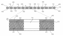
- FIG. 1 shows a plan view and an enlarged view of part B of a heat dissipation sheet according to a first embodiment of the present invention.
- FIG. 2 shows a cross-sectional view of the heat dissipation sheet of FIG. 1 taken along the line AA, an enlarged view of part C thereof, and an enlarged view of part D thereof, respectively.
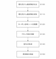
- FIG. 3 shows an example of a flow of main steps of a method for manufacturing a heat-dissipating sheet according to the first embodiment of the present invention.
- FIG. 4 shows the state of each step of the manufacturing method of FIG. 3 in plan view and cross-sectional view.
- FIG. 5 shows the state of each step following FIG. 4 in a cross-sectional view.
- FIG. 6 shows the state of each step following FIG.
- FIG. 7 shows the state of each step following FIG. 6 in a cross-sectional view.
- FIG. 8 shows a perspective view of each step following FIG.
- FIG. 9 shows a plan view and an enlarged view of part B of a heat dissipation sheet according to a second embodiment of the present invention.
- FIG. 10 shows a cross-sectional view of the heat dissipation sheet of FIG. 9 taken along line AA, an enlarged view of part C thereof, and an enlarged view of part D thereof, respectively.
- 11 shows a plan view of a first modification of the heat dissipation sheet of FIG. 9.
- FIG. FIG. 12 is a view showing a second modification of the heat dissipation sheet of FIG.
- FIG. 13 is a view showing a third modification of the heat dissipation sheet of FIG. 9, showing a cross-sectional view similar to the cross-sectional view taken along line AA of FIG. 9 and an enlarged view of part C thereof.
- FIG. 14 shows a cross-sectional view of a situation in the middle of sandwiching the heat dissipation sheet according to the third modification between the cooling member and the heat source.
- FIG. 15 shows a cross-sectional view of a situation in which the cooling member and the heat source completely sandwich the heat radiation sheet, proceeding further from the situation in FIG. FIG.
- FIG. 16 shows an example (16A) in which a lubricant is supplied to the surface of a conventional hole-free heat radiation sheet and a heat sink, which is an example of a cooling member, is brought into contact with the heat radiation sheet.
- a cross-sectional view is shown for comparison with an example (16B) in which a heat sink is brought into contact with a heat radiation sheet by supplying an agent.
- FIG. 17 shows a plan view of a heat dissipation sheet according to a fourth modification and a cross-sectional view of the plan view taken along the line AA.
- FIG. 18 shows a plan view of a heat dissipation sheet according to the fifth example and a cross-sectional view of the plan view taken along the line AA.
- FIG. 19 shows a plan view of a heat dissipation sheet according to a sixth modification and a cross-sectional view of the plan view taken along the line AA.
- FIG. 20 shows a plan view of a heat dissipation sheet according to a seventh modification and a cross-sectional view of the plan view taken along the line AA.
- FIG. 21 shows the flow of the manufacturing method in which the holes are formed after the step of cutting the block.
- FIG. 22 shows the flow of the manufacturing method for supplying lubricant to the rubber-like elastic body after the pore forming step.
- FIG. 23 shows a photograph of a heat dissipation sheet according to the first modification of the second embodiment.
- FIG. 24 shows a modification of the flow diagram of FIG.
- FIG. 1 shows a plan view of a heat dissipating sheet according to a first embodiment of the present invention and an enlarged view of a portion B thereof.
- FIG. 2 shows a cross-sectional view of the heat dissipation sheet of FIG. 1 taken along the line AA, an enlarged view of part C thereof, and an enlarged view of part D thereof, respectively.
- the heat-dissipating sheet 1 is a sheet with excellent heat conductivity that conducts heat from a heat source to a member on the cooling side to enable heat dissipation from the heat source.
- a "heat radiation sheet” may also be referred to as a "thermally conductive sheet”.
- the heat dissipation sheet 1 is configured such that one surface 11 in the thickness direction of the rubber-like elastic body 10 is in contact with a heat source, and the other surface 12 in the thickness direction is in contact with a member on the cooling side. It is a sheet that is used by being placed between members on the cooling side.
- the heat-dissipating sheet 1 includes a sheet-like rubber-like elastic body 10 and carbon fibers 20 embedded and oriented obliquely with respect to the thickness direction of the rubber-like elastic body 10 (vertical direction in FIG. 2). .
- the surfaces 11 and 12 are the widest surfaces of the rubber-like elastic body 10, and mean the surfaces of the rubber-like elastic body 10 that are visible in a plan view.
- the surface 11 means "the surface on the front side”.
- Surface 12 means "back side”.
- the carbon fiber 20 is an example of an elongated thermally conductive filler.
- the thermally conductive filler is superior in thermal conductivity to the rubber-like elastic body 10 .
- the rubber-like elastic body 10 has at least one hole 14 oriented obliquely with respect to its thickness direction (vertical direction in FIG. 2). Both ends 21 and 22 of the carbon fiber 20 are exposed to the surfaces 11 and 12 of the rubber-like elastic body 10 .
- the pores 14 are preferably more than 0% and less than 80%, more preferably more than 20% and less than 60%, with respect to the area of the surface 11 or the surface 12 of the rubber-like elastic body 10 . This also applies to the second embodiment, which will be described later.
- the inclination angle of the pores 14 with respect to the surface 11 or the surface 12 is preferably greater than 0° and less than 80°, more preferably greater than 20° and less than 50°. This also applies to the second embodiment, which will be described later.
- the heat-dissipating sheet 1 is a member in which a plurality of rubber-like elastic bodies 10 are laminated to form a single sheet in plan view.
- silicone rubber 30 obtained by curing uncured liquid rubber is preferably arranged between a plurality of rubber-like elastic bodies 10. As shown in FIG. The silicone rubber 30 is preferably arranged between the rubber-like elastic bodies 10 and the holes 14 in the thickness direction of the heat-dissipating sheet 1 (vertical direction in FIG. 2) (enlarged view of part C in FIG. 2). ).
- the uncured liquid rubber serves as an adhesive that bonds the rubber-like elastic bodies 10 together.
- the rubber-like elastic body 10 is not particularly limited and can be appropriately selected according to the performance required for the heat dissipation sheet.
- examples thereof include thermosetting resins and thermoplastic resins.
- Thermosetting resins include, for example, elastomeric thermosetting resins such as silicone rubber, silicone resin, polyurethane resin, and epoxy resin.
- thermoplastic resins include synthetic rubbers, polyethylene resins, polyurethane resins, ABS resins, elastomeric thermoplastic resins such as soft vinyl chloride resins, and the like. These may be used individually by 1 type, and may use 2 or more types together.
- the rubber-like elastic body 10 may contain the resin material as described above and a filler having higher thermal conductivity than the resin material. As a result, the rubber-like elastic body 10 has a higher thermal conductivity than the rubber-like elastic body 10 made of only a resin material, so that the thermal conductivity from the heat source to the member on the cooling side can be further increased.
- fillers examples include aluminum oxide (Al 2 O 3 ), aluminum nitride (AlN), cubic boron nitride (cBN), hexagonal boron nitride (hBN), zinc oxide, silicon carbide, aluminum hydroxide, and diamond. Particulate, fibrous, plate-like or needle-like fillers can be selected. A filler with high insulating properties is more preferred.
- the carbon fiber 20 as an example of an elongated thermally conductive filler preferably has an angle ⁇ 1 of greater than 45° and 85° with respect to the surfaces 11 and 12 of the rubber-like elastic body 10 . It is embedded in the rubber-like elastic body 10 oriented so as to be smaller than °.
- angle ⁇ 1 By making the angle ⁇ 1 larger than 45° in the heat dissipation sheet 1, it is possible to suppress a decrease in thermal conductivity in the thickness direction. Further, in the heat-dissipating sheet 1, by setting the angle ⁇ 1 to be smaller than 85°, it is possible to suppress an increase in hardness.
- ⁇ 1 may be an angle larger than 0° and 45° or less.
- Both ends 21 and 22 of carbon fiber 20 are preferably flush with surfaces 11 and 12 of rubber-like elastic body 10, respectively, and do not protrude or dent greatly from surfaces 11 and 12, respectively.
- the diameter ⁇ 1 of both ends 21 and 22 exposed on the surfaces 11 and 12 of the rubber-like elastic body 10 is preferably larger than the diameter ⁇ 2 of the region 23 embedded in the rubber-like elastic body 10.
- the magnitude of ⁇ 1 with respect to ⁇ 2 is preferably 1 ⁇ 1/ ⁇ 2 ⁇ 2, more preferably 1.5 ⁇ 1/ ⁇ 2 ⁇ 2.
- both ends 21 and 22 of the carbon fibers 20 are larger than the diameter ⁇ 2 of the other region 23, for example, the external force in the direction of pulling out the carbon fibers 20 (orientation direction of the carbon fibers 20) is Even if it is applied, it is possible to prevent the carbon fibers 20 from being pulled out from the rubber-like elastic body 10 .
- both ends 21 and 22 of the carbon fibers 20 having a diameter ⁇ 1 are in contact with the heat source or the cold-side member, so the contact area between the carbon fibers 20 and the heat source or the cooling-side member increases. , can increase the thermal conductivity.
- the orientation angle ⁇ 1 of the carbon fibers 20 is not limited to the above range as long as the carbon fibers 20 are oriented obliquely with respect to the thickness direction of the rubber-like elastic body 10 .
- the carbon fibers 20 are not particularly limited, they are preferably anisotropic pitch-based carbon fibers. However, the carbon fibers 20 are not limited to anisotropic pitch-based carbon fibers. or a mixture of two or more of these carbon fibers.
- the fiber length of the carbon fibers 20 is preferably 0.002 mm to 10 mm, more preferably 0.005 mm to 7.5 mm.
- the fiber diameter of the carbon fibers 20 is preferably 1 ⁇ m to 50 ⁇ m, more preferably 5 to 25 ⁇ m.
- Silicone rubber 30 is hardened uncured liquid rubber and has low fluidity or is in a solid state.
- Uncured liquid rubber is a highly flowable rubber that can be cured by any desired method. Examples of curing methods for the uncured liquid rubber include heating, light irradiation, electron beam irradiation, and curing with a catalyst or curing agent.
- uncured liquid rubber examples include liquid silicone rubber, liquid natural rubber, liquid isoprene rubber, liquid butadiene rubber, liquid styrene-butadiene rubber, liquid butyl rubber, liquid nitrile rubber, liquid ethylene-propylene rubber, liquid chloroprene rubber, liquid chloroprene rubber, Examples include sulfonated polyethylene rubber, liquid urethane rubber, and liquid fluororubber.
- liquid silicone rubbers are preferred because they are less susceptible to dimensional change and warpage after curing, have a small compression set, and have high heat resistance.
- the liquid silicone rubber may be either condensation type or addition type.
- the heat-dissipating sheet 1 preferably has a plurality of holes 14 oriented obliquely with respect to the thickness direction of the rubber-like elastic body 10 (vertical direction in FIG. 2).
- the holes 14 are preferably through holes penetrating from one surface 11 to the other surface 12 of the rubber-like elastic body 10 in the thickness direction.
- heat dissipation sheet 1 has a plurality of holes 14 arranged at predetermined intervals on surfaces 11 and 12 .
- the number, arrangement, form, and the like of the holes 14 are not particularly limited, and are preferably designed appropriately according to the performance required of the heat dissipation sheet.
- the holes 14 do not have to penetrate from one surface 11 to the other surface 12 .
- the holes 14 are provided substantially parallel to the orientation direction of the carbon fibers 20 (see enlarged view of part C in FIG. 2). However, as long as the pores 14 are oriented obliquely with respect to the thickness direction of the rubber-like elastic body 10, they do not have to be arranged parallel to the orientation direction of the carbon fibers 20.
- FIG. The heat-dissipating sheet 1 configured in this way can suppress an increase in hardness due to the holes 14 oriented obliquely with respect to the thickness direction. Moreover, the heat dissipation sheet 1 is compressed in the thickness direction between the heat source and the member on the cooling side. Since the heat dissipation sheet 1 has the holes 14 , it is possible to reduce the stress on the carbon fibers 20 and suppress the breakage of the carbon fibers 20 even when deformed by the compression.
- the heat-dissipating sheet 1 preferably has surfaces 11 and 12 perpendicular to its thickness direction (vertical direction in FIG. 2) with an arithmetic mean roughness Ra of 1.0 ⁇ m or more and 1.8 ⁇ m or less. Moreover, the heat dissipation sheet 1 preferably has a ten-point average roughness Rz of the surfaces 11 and 12 of 7.7 or more and 18 ⁇ m or less.
- the arithmetic mean roughness Ra is a value measured according to JIS B 0601-2001.
- the ten-point average roughness Rz is a value measured according to JIS B 0601-1994.
- the surfaces 11 and 12 perpendicular to the thickness direction of the heat dissipating sheet 1 are flattened, so that the heat source and the carbon fibers 20 can more reliably contact each other. It is possible to increase the thermal conductivity.
- the manufacturing method of the heat-dissipating sheet 1 includes a step of ejecting a curable rubber composition containing carbon fibers 20 onto the plane of the planar body along a first predetermined direction in a plurality of rows, and The resulting curable rubber composition is molded into a sheet and cured to form a carbon-containing sheet (filler-containing sheet Example), a plurality of carbon-containing sheets are laminated with uncured liquid rubber arranged between the carbon-containing sheets, the uncured liquid rubber is cured, and the orientation of the carbon fibers 20 is oriented.
- a carbon-containing sheet iller-containing sheet Example
- It includes a stacking step of forming blocks that are aligned and stacked, and a cutting step of cutting the blocks into sheets in a direction oblique to the direction in which the carbon fibers 20 are oriented.
- a stacking step of forming blocks that are aligned and stacked and a cutting step of cutting the blocks into sheets in a direction oblique to the direction in which the carbon fibers 20 are oriented.
- FIG. 3 shows an example of the flow of main steps of the method for manufacturing a heat dissipation sheet according to the first embodiment of the present invention.
- FIG. 4 shows the state of each step of the manufacturing method of FIG. 3 in plan view and cross-sectional view.
- FIG. 5 shows the state of each step following FIG. 4 in a cross-sectional view.
- FIG. 6 shows the state of each step following FIG. 5 in plan view.
- FIG. 7 shows the state of each step following FIG. 6 in a cross-sectional view.
- FIG. 8 shows a perspective view of each step following FIG.
- the carbon fibers 20 are exaggeratedly drawn for explanation of the manufacturing process.
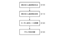
- the heat dissipation sheet 1 can be manufactured through a discharge process (S100), a molding process (S110), a lamination process (S120), and a cutting process (S130). S100 to S130 will be described in detail below with reference to FIGS.
- Ejection step (S100) In this step, the curable rubber composition 70 containing the carbon fibers 20 is placed on the plane of a film (an example of a plane body) 72 along the first predetermined direction D1 (vertical direction in FIG. 4A). This is the step of discharging (see FIG. 4).
- the ejection step (S100) includes a recess 41 (see the EE line cross-sectional view of FIG. See), it is preferable to discharge the curable rubber composition 70 onto the film 72 while the film 72 is placed thereon.
- the curable rubber composition 70 linearly discharged along the first predetermined direction D1 is spread in a direction perpendicular to the first predetermined direction D1 (horizontal direction in FIG. 4A). A plurality of lines are discharged so as to line up (see FIG. 4(a)), and a sheet-like curable rubber composition 70 is formed on the film 72 (see FIG. 4(b)).
- the curable rubber composition 70 is a composition that becomes the rubber-like elastic body 10 after curing.
- the carbon fibers 20 can be oriented along the first predetermined direction D1 by discharging the curable rubber composition 70 containing the carbon fibers 20 along the first predetermined direction D1. .
- the film 72 is preferably a film made of resin.
- resins include polyethylene terephthalate (PET), polyethylene naphthalate, polyethylene isophthalate, polybutylene terephthalate, polyacetate, polycarbonate, polyphenylene sulfide, polyamide, polyvinyl chloride, and polyvinylidene chloride.
- PET polyethylene terephthalate
- polyethylene naphthalate polyethylene isophthalate
- polybutylene terephthalate polyacetate
- polycarbonate polyphenylene sulfide
- polyamide polyvinyl chloride
- polyvinylidene chloride polyvinylidene chloride
- the curable rubber composition 70 discharged onto the film 72 is formed into a sheet and cured, and the carbon fibers 20 are oriented in the first predetermined direction D1 and at least one sheet along the second predetermined direction D2.
- the second predetermined direction D2 is the same direction as the first predetermined direction D1 (the depth direction in FIG. 5).
- the first predetermined direction deviates from the second predetermined direction by preferably within 20 degrees, more preferably within 10 degrees, and even more preferably within 5 degrees.
- the carbon-containing sheet 76 includes a plurality of recesses 78 at predetermined intervals in a direction perpendicular to the second predetermined direction D2 (horizontal direction in FIG. 5). More specifically, first, a plane of a film (an example of a plane body) 74 is placed on the curable rubber composition 70 discharged onto the film 72 . Film 74 is preferably constructed of the same material as film 72 described above. Next, an upper mold 50 constituting the mold 60 is prepared, placed on the recess 41 side of the lower mold 40, and the lower mold 40 and the upper mold 50 are closed (FIGS. 5(c) and (d)). ).
- the upper mold 50 has a recess 51 on the surface facing the recess 41 of the lower mold 40 .
- the recess 51 has, on its inner bottom surface, an unevenness 52 on which the recess 78 can be transferred.
- the mold 60 is clamped, it is heated to mold the curable rubber composition 70 (see FIG. 5(e)).
- the curable rubber composition 70 is cured to form the rubbery elastic body 10 containing the carbon fibers 20 .
- recesses 78 are formed by transferring the unevenness 52 .
- the mold 60 is opened and the films 72 and 74 are peeled off to form a carbon-containing sheet 76 (see FIG. 5(f)).
- the carbon-containing sheet 76 is a sheet containing the rubber-like elastic body 10 and the carbon fibers 20 oriented along the first predetermined direction D1 (the depth direction of the paper surface in FIG. 5(f)). Also, the carbon-containing sheet 76 is a sheet provided with a plurality of recesses 78 at predetermined intervals in a direction perpendicular to the second predetermined direction D2 (horizontal direction in FIG. 5) (see FIG. 6(g)).
- two types of carbon-containing sheets 80, 82 are cut out from the carbon-containing sheet 76 (see FIG. 6(g)).
- the carbon-containing sheet 80 and the carbon-containing sheet 82 are carbon-containing sheets having different positions of the concave portions 78 in the direction perpendicular to the second predetermined direction D2 (horizontal direction in FIG. 6).
- the carbon-containing sheets 80 and 82 are sheets containing the carbon fibers 20 oriented along the first predetermined direction D1 (vertical direction in FIG. 6).
- the forming step (S110) preferably includes forming the carbon-containing sheet 76 in the second predetermined direction so that the positions of the concave portions 78 are different in the direction perpendicular to the second predetermined direction D2 (horizontal direction in FIG. 6).
- Carbon-containing sheets 80 and 82 are formed by cutting along D2 (the vertical direction in FIG. 6).
- the carbon-containing sheet 80 and the carbon-containing sheet 82 are sheets of the same size, but they may be sheets of different sizes.
- the method of cutting out the carbon-containing sheets 80 and 82 from the carbon-containing sheet 76 is not particularly limited as long as it is a method capable of forming two types of carbon-containing sheets 80 and 82 .
- Lamination step In this step, a plurality of carbon-containing sheets 80 and 82 are laminated with uncured liquid rubber 85 interposed between the carbon-containing sheets 80 and 82, and the uncured liquid rubber 85 is cured to form the carbon fibers 20.
- This is the step of forming block bodies 90 laminated with aligned orientation (see FIG. 7).
- the positions of the concave portions 78 of the carbon-containing sheets 80 and 82 are different in the thickness direction (vertical direction in FIG. 7) of the carbon-containing sheets 80 and 82.
- the uncured liquid rubber 85 is placed between the carbon-containing sheets 80 and 82, and the carbon-containing sheet 82 is stacked (see FIG. 7(h)). At this time, the two carbon-containing sheets 80 and 82 are stacked such that the orientation directions D1 of the carbon fibers 20 contained in the two carbon-containing sheets 80 and 82 are the same. overlap.
- the uncured liquid rubber 85 is preferably applied to the bottom surface of the carbon-containing sheet 82 (that is, the smooth surface). This is because it is easier to apply the uncured liquid rubber 85 to the garbon-containing sheet 82 in a thin and uniform thickness.
- the two carbon-containing sheets 80 and 82 stacked with the uncured liquid rubber 80 interposed therebetween are arranged so that the recesses 78 are positioned at different positions in the thickness direction of the carbon-containing sheets 80 and 82 .
- the carbon-containing sheets 80, 82 are stacked. That is, in the stacking step (S120), the recessed portions 78 of the carbon-containing sheet 80 and the recessed portions 78 of the carbon-containing sheet 82 are not arranged on the same straight line along the thickness direction (vertical direction in FIG. 7). Two carbon-containing sheets 80, 82 are stacked (see FIGS. 7(h) and (i)).
- the uncured liquid rubber 85 becomes the silicone rubber 30 after curing, and is preferably liquid silicone rubber. Further, in this embodiment, the uncured liquid rubber 85 plays a role of an adhesive that bonds the carbon-containing sheets 80 and 82 together. Then, the uncured liquid rubber 85 is cured while the plurality of carbon-containing sheets 80 and 82 are laminated to form a block body 90 (see FIG. 7(j)).
- the block body 90 is a laminate in which the orientation directions D1 of the carbon fibers 20 contained in the plurality of carbon-containing sheets 80 and 82 are the same (see FIG. 8(k)).
- the uncured liquid rubber 85 preferably has a hardness equal to or lower than that of the carbon-containing sheets 80 and 82 after curing. This is because the increase in hardness of the block body 90 can be suppressed and flexibility can be imparted.
- the stacking step (S120) may be performed by stacking the carbon-containing sheets 82 and performing a curing process such as heating (or cooling).
- This step is a step of cutting the block body 90 into a sheet in a direction oblique to the orientation direction D1 of the carbon fibers 20 (see FIG. 8). More specifically, it is cut into a predetermined thickness at an angle ⁇ 2 larger than 45° and smaller than 85° with respect to the orientation direction D1 of the carbon fibers 20 (see FIG. 8(k)).
- the predetermined thickness is preferably 0.01 mm to 10 mm, more preferably 0.05 mm to 5 mm.
- the cutting means is not particularly limited as long as it can cut into a predetermined thickness, such as a known cutter or slicer, but it is preferable to slice using a rotating blade as the cutting means. .
- the diameter ⁇ 1 of the cut surfaces 21 and 22 is compared with the diameter ⁇ 2 of the region 23 embedded in the rubber-like elastic body 10. It can be large (see Figures 1 and 2).
- FIGS. 8(l) and 8(m) show the figure seen from the arrow F direction in FIG. 8(l).
- Carbon fibers 20 and holes 14 are embedded obliquely with respect to the thickness direction (the vertical direction in FIG. 8(m)) of the heat dissipation sheet 1 manufactured in this manner (see FIG. 8(m). reference).
- both ends 21 and 22 of the carbon fibers 20 are exposed on the cut surfaces (that is, the surfaces 11 and 12 of the rubber-like elastic body 10).
- the diameter ⁇ 1 of both end portions 21 and 22 exposed on the cut surfaces 11 and 12 of the carbon fiber 20 is larger than the diameter ⁇ 2 of the region 23 embedded in the rubber-like elastic body 10 .
- the heat dissipation sheet 1 manufactured in this way the contact area between the carbon fibers 20 and the member on the heat source or the cooling side is increased, and the thermal conductivity can be improved. Further, according to the heat dissipation sheet 1, for example, even when an external force is applied in the direction of pulling out the carbon fibers 20 (orientation direction Do of the carbon fibers 20), the carbon fibers 20 are pulled out of the rubber-like elastic body 10. can be suppressed. In addition, since the heat-dissipating sheet 1 is cut so as to reduce the surface roughness in the cutting step (S130), the cut surface becomes flat, and the heat source and the carbon fibers 20 can more reliably contact each other. Therefore, thermal conductivity can be further increased.
- the heat dissipation sheet 1 since the heat dissipation sheet 1 has high thermal conductivity as described above, it is not necessary to increase the filling rate of the carbon fibers 20 in order to increase the thermal conductivity. Therefore, the heat dissipation sheet 1 can suppress an increase in hardness due to an increase in the filling rate of the carbon fibers 20, and can realize low hardness and high thermal conductivity.
- the heat dissipation sheet 1 since the heat dissipation sheet 1 is provided with the holes 14 oriented obliquely to the thickness direction, the hardness of the heat dissipation sheet 1 is suppressed from increasing, and even when the heat dissipation sheet 1 is deformed due to compression in the thickness direction, the carbon fibers 20 stress can be reduced, and breakage of the carbon fibers 20 can be suppressed.
- At least one of the surfaces 11 and 12 perpendicular to the thickness direction of the heat dissipation sheet 1 may be coated with a resin.
- the resin used for this coating is not particularly limited, and examples thereof include thermosetting resins and thermoplastic resins similar to the material of the rubber-like elastic body 10 described above. Further, like the rubber-like elastic body 10, it may contain a resin material as described above and a filler having higher thermal conductivity than the resin material. As the filler, the same filler as the rubber-like elastic body 10 can be used. According to the heat-dissipating sheet 1 configured in this way, it is possible to further prevent the carbon fibers 20 from falling off from the rubber-like elastic body 10 due to the coating on the surfaces 11 and 12 .
- the thermally conductive sheet 1 can reduce deterioration in thermal conductivity due to coating by including a filler having high thermal conductivity in the resin material used for coating.
- the heat dissipation sheet 1 can be manufactured by coating the surfaces 11, 12 after the cutting step (S130).
- the carbon-containing sheet 76 is formed with the concave portions 78 by molding with the mold 60, but the concave portions 78 may be formed by other methods such as cutting and etching.
- the molding step (S110) instead of the upper mold 50, an upper mold that does not have the unevenness 52 on the inner bottom surface of the recess 51 is used to form the carbon-containing sheet 76 that does not have the recess 78.
- the recesses 78 may be formed in the carbon-containing sheet 76 by using a method such as cutting or etching.
- the carbon-containing sheet 76 was cut out to form the two types of carbon-containing sheets 80 and 82.
- sheet 82 may be formed.
- the two types of carbon-containing sheets 80 and 82 may be formed by the same method as that for forming the carbon-containing sheet 76 in the molding process.
- the carbon-containing sheets 80 and 82 are subjected to a technique such as cutting or etching. may be used to form the recess 78 .
- the plurality of carbon-containing sheets 80, 82 are stacked such that the positions of the concave portions 78 of the carbon-containing sheets 80, 82 are the same in the thickness direction of the carbon-containing sheets 80, 82.
- a trimming process for trimming the excess area of the carbon-containing sheet 76 may be performed.
- FIG. 9 shows a plan view of a heat dissipation sheet according to the second embodiment of the present invention and an enlarged view of part B thereof.
- FIG. 10 shows a cross-sectional view of the heat dissipation sheet of FIG. 9 taken along line AA, an enlarged view of part C thereof, and an enlarged view of part D thereof, respectively.
- the heat dissipation sheet 1 includes a sheet-like rubber-like elastic body 10 and carbon fibers 20 embedded in the rubber-like elastic body 10 and oriented obliquely with respect to the thickness direction of the rubber-like elastic body 10 .
- the rubber-like elastic body 10 is a single non-laminated sheet.
- the rubber-like elastic body 10 has at least one pore 14 oriented in its thickness direction. Both ends of the carbon fibers 20 are exposed on the surface of the rubber-like elastic body 10 .
- the holes 14 are through holes that connect the surfaces 11 and 12 of the rubber-like elastic body 10 in the thickness direction.
- the holes 14 are through holes parallel to the thickness direction of the rubber-like elastic body 10 .
- the carbon fibers 20 exist in the rubber-like elastic body 10 at an angle of ⁇ 1 (acute angle) with respect to the surface 12 of the rubber-like elastic body 10 .
- the diameter ⁇ 1 of the carbon fibers 20 exposed on the surfaces 11 and 12 of the rubber-like elastic body 10 is preferably larger than the diameter ⁇ 2 of the part embedded in the rubber-like elastic body 10 .
- the magnitude of ⁇ 1 with respect to ⁇ 2 is here 1 ⁇ 1/ ⁇ 2 ⁇ 2, more preferably 1.1 ⁇ 1/ ⁇ 2 ⁇ 1.5.
- the carbon fibers 20 are in contact with the heat source or the cooling member at the portion having the diameter ⁇ 1.
- the orientation angle ⁇ 1 of the carbon fibers 20 is not limited to the above range as long as the carbon fibers 20 are oriented obliquely with respect to the thickness direction of the rubber-like elastic body 10 .
- the holes 14 exhibit the effect of facilitating the deformation of the heat dissipation sheet 1, and also exhibit the effect of retaining lubricant, as will be described later.
- the retention effect of the lubricant will be described later in detail.
- FIG. 11 shows a plan view of a first modification of the heat dissipation sheet of FIG.
- the heat-dissipating sheet 1 according to the first modification is a laminated sheet of a plurality of sheets, like the heat-dissipating sheet 1 according to the first embodiment.
- silicone rubber 30, which is obtained by curing uncured liquid rubber, is preferably arranged between a plurality of rubber-like elastic bodies 10. As shown in FIG. In other words, the silicone rubber 30 is arranged between one hole 14 and another hole 14 .
- the silicone rubber 30 is preferably arranged between the rubber-like elastic bodies 10 and the holes 14 in the thickness direction of the heat dissipation sheet 1 .
- the uncured liquid rubber serves as an adhesive that bonds the rubber-like elastic bodies 10 together.
- FIG. 12 is a view showing a second modification of the heat dissipation sheet of FIG. 9, showing a cross-sectional view similar to the cross-sectional view taken along line AA of FIG. 9 and an enlarged view of part C thereof.
- the heat dissipation sheet 1 according to the second modification includes at least one hole 14 oriented obliquely with respect to the thickness direction of the rubber-like elastic body 10, as in the first embodiment.
- the angle at which the holes 14 are tilted with respect to the surface 12 is the same ⁇ 1 (acute angle) as the angle at which the carbon fibers 20 are tilted with respect to the surface 12 .
- the inclination angle of the holes 14 and the inclination angle of the carbon fibers 20 may be different.
- FIG. 13 is a view showing a third modification of the heat dissipation sheet of FIG. 9, showing a cross-sectional view similar to the cross-sectional view taken along line AA of FIG. 9 and an enlarged view of part C thereof.
- the heat dissipation sheet 1 according to the third modification has a lubricant coating layer 45 on at least one of the surfaces 11 and 12 of the rubber-like elastic body 10 .
- the heat dissipation sheet 1 has coat layers 45 on both surfaces 11 and 12 .
- the coat layer 45 may be provided only on one of the surfaces 11 and 12 .
- the coat layer 45 is provided in the region other than the pores 14 of the rubber-like elastic body 10 .
- part of the lubricant forming the coating layer 45 may exist in the pores 14 . In that case, it is preferable not to fill all the holes 14 with the lubricant.
- the lubricant in the coat layer 45 and the pores 14 has a high viscosity such that it does not flow easily from the rubber-like elastic body 10 , but is preferably softer than the rubber-like elastic body 10 .
- the coat layer 45 is mainly composed of grease as an example of a lubricant, and is a layer that has high viscosity and can retain its shape.
- Greases include, for example, modified silicone, silicone oil, and ester oil-based greases containing fillers with higher thermal conductivity than the base material.
- fillers with high thermal conductivity are aluminum oxide ( Al2O3 ), aluminum nitride ( AlN ), cubic boron nitride (cBN), hexagonal boron nitride (hBN), zinc oxide, silicon carbide, aluminum hydroxide. , particulate, fibrous, plate-like or needle-like fillers typified by diamond.
- a filler with high insulating properties is more preferred.
- the grease may use the base material alone.
- the coat layer 45 can prevent the carbon fibers 20 from falling off from the rubber-like elastic body 10 .
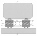
- FIG. 14 shows a cross-sectional view of a situation in which the heat dissipation sheet according to the third modification is sandwiched between the cooling member and the heat source.
- FIG. 15 shows a cross-sectional view of a situation in which the cooling member and the heat source completely sandwich the heat radiation sheet, proceeding further from the situation in FIG.
- cooling member is broadly interpreted to include, in addition to positively cooling members, members that are lower in temperature than the heat source and are capable of dissipating heat from the heat source.
- the heat dissipation sheet 1 according to the third modification is sandwiched between the cooling member 95 and the heat source 96, the coat layers 45 formed on both sides in the thickness direction of the rubber-like elastic body 10 are compressed, and the lubricant 45a is an empty space. Go into hole 14 (see arrow F). In FIG. 15, the cavity 14 is filled with a lubricant 45a. However, the holes 14 may not be filled with the lubricant 45a, and there may be spaces (existence of air) in the holes 14.
- FIG. 16 shows an example (16A) in which a lubricant is supplied to the surface of a conventional hole-free heat radiation sheet and a heat sink, which is an example of a cooling member, is brought into contact with the heat radiation sheet.
- a cross-sectional view is shown for comparison with an example (16B) in which a heat sink is brought into contact with a heat radiation sheet by supplying an agent. Note that in FIG. 16, the heat source is omitted from the surface of the heat dissipation sheet opposite to the heat sink.
- FIG. 17 shows a plan view of a heat dissipation sheet according to a fourth modification and a cross-sectional view of the plan view taken along the line AA.
- the coating layer 45 of the lubricant 45a is provided on both the front surface and the back surface of the rubber-like elastic body 10. , and the holes 14 do not have the lubricant 45a.
- the number of holes 14 and the shape in plan view are different from those of the third modification.
- the holes 14 have a rectangular or square shape in plan view, and are provided with a total of 80 holes 14 of 10 columns ⁇ 8 rows.
- the rubber-like elastic body 10 When the heat dissipation sheet 1 is sandwiched between the heat source and the cooling member in the thickness direction, the rubber-like elastic body 10 is compressed by the pressure applied in the thickness direction, and the lubricant constituting the coat layer 45 is applied. 45a enters the hole 45a. As a result, the risk of the lubricant 45a overflowing to the outside of the heat dissipation sheet 1 can be reduced.
- FIG. 18 shows a plan view of a heat dissipation sheet according to the fifth example and a cross-sectional view taken along the line AA of the plan view.
- the heat dissipation sheet 1 according to the fifth modification has rubber-like elastic bodies 10 similar to the heat dissipation sheet 1 according to the fourth modification. That is, the number and shape of the holes 14 in the fifth modification are the same as in the fourth modification.
- the heat-dissipating sheet 1 according to the fifth modification has lubricant 45 a in some of the holes 14 among all the holes 14 . More specifically, the pores 14 located at the in-plane outermost periphery of the rubber-like elastic body 10 do not contain the lubricant 45a, and the pores in the region inside the plane from the pores 14 located at the in-plane outermost periphery. 14 contains a lubricant 45a.
- Neither the front surface nor the back surface of the rubber-like elastic body 10 is provided with the coat layer 45 .
- the rubber-like elastic body 10 is compressed by the pressure applied in the thickness direction, and the lubricant 45a in the holes 14 is compressed. overflows from the holes 45 a to the front and back surfaces of the rubber-like elastic body 10 .
- the holes 14 located at the in-plane outermost periphery contribute to suppressing the overflow of the lubricant 45 a to the outside of the heat dissipation sheet 1 . Therefore, the risk of the lubricant 45a overflowing to the outside of the heat dissipation sheet 1 can be further reduced.
- FIG. 19 shows a plan view of a heat dissipation sheet according to the sixth modification and a cross-sectional view of the plan view taken along the line AA.
- the heat dissipation sheet 1 according to the sixth modification has rubber-like elastic bodies 10 similar to the heat dissipation sheet 1 according to the fourth modification. That is, the number and shape of the holes 14 in the sixth modification are the same as in the fourth modification.
- the heat dissipation sheet 1 according to the sixth modification has the lubricant 45 a in some of the holes 14 among all the holes 14 . More specifically, the pores 14 located on the outermost periphery in the plane of the rubber-like elastic body 10 do not contain the lubricant 45a, and the lubricant 45a is contained in a region inside the surface of the pores 14 located on the outermost periphery in the plane. 45a.
- a lubricant 45a is filled in the holes 14 in the region on the inner side of the plane.
- a coat layer 45 of a lubricant 45a is provided on the inner surface area other than the holes 14, that is, on the front side surface and the back side surface of the rubber-like elastic body 10.
- the holes 14 positioned at the in-plane outermost periphery contribute to suppressing the lubricant 45a from overflowing to the outside of the heat dissipation sheet 1, as in the fifth modification. Therefore, the risk of the lubricant 45a overflowing to the outside of the heat dissipation sheet 1 can be further reduced.
- FIG. 20 shows a plan view of a heat dissipation sheet according to the seventh modification and a cross-sectional view of the plan view taken along the line AA.
- the heat dissipation sheet 1 according to the seventh modification has rubber-like elastic bodies 10 similar to the heat dissipation sheet 1 according to the fourth modification. That is, the number and shape of the holes 14 in the seventh modified example are the same as in the fourth modified example.
- the pores 14 located on the in-plane outermost periphery of the rubber-like elastic body 10 do not contain the lubricant 45a, and the pores 14 located on the in-plane outermost periphery do not contain the lubricant 45a. It has a lubricant 45a in the inner and inner regions.
- the seventh modification differs from the sixth modification in that the lubricant 45a in the pores 14 in the in-plane inner region does not fill the entire volume of the pores 14, but rather extends along the length of the pores 14. It is a point that does not satisfy a part of That is, in the seventh modified example, spaces 105 without lubricant 45a exist in the longitudinal direction of holes 14 containing lubricant 45a. Even with such a heat dissipation sheet 1, the same effects as in the sixth modification can be exhibited. A wall that divides the air hole 14 into two may be formed instead of the space 105 .
- the formation of the holes 14 in the heat dissipation sheet 1 may be performed after S130 instead of before S120.
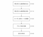
- FIG. 21 shows the flow of the manufacturing method for forming holes after the step of cutting the block body.
- the manufacturing method of the heat dissipation sheet shown in FIG. 21 includes: A discharging step (S100) of discharging a curable rubber composition 70 containing carbon fibers 20 in a plurality of rows along a first predetermined direction D1 on the plane of a film (an example of a plane body) 72; a forming step (S110) of forming a carbon-containing sheet 76 in which the curable rubber composition 70 discharged onto a flat surface is formed into a sheet and cured to form a carbon-containing sheet 76 in which the carbon fibers 20 are oriented in the first predetermined direction D1; A block in which a plurality of carbon-containing sheets 76 are laminated with uncured liquid rubber 85 arranged between the carbon-containing sheets 76, the uncured liquid rubber 85 is cured, and the orientation of the carbon fibers 20 is aligned.
- the sheet may be cut at an angle larger than 45° and smaller than 85° with respect to the orientation direction of the carbon fibers 20.
- the molding step (S110) in the flow of FIG. 21 does not form the concave portion 78 during molding. That is, in the flow of FIG. 21, the holes 14 are not formed by the concave portions 78, and the holes 14 are formed after the cutting step (S130) (hole forming step: S140).
- the manufacturing method other than forming the recesses 78 during molding and forming the holes 14 after cutting has already been explained with reference to FIGS.
- the flow of FIG. 21 can also be used when manufacturing the heat dissipation sheet 1 of FIGS.
- FIG. 22 shows the flow of the manufacturing method for supplying the lubricant to the rubber-like elastic body after the pore forming process.
- FIG. 22 shows an exemplary manufacturing method of the heat dissipation sheet 1 according to the second embodiment.
- the lubricant 45a is supplied to at least one of the front and back surfaces of the rubber-like elastic body 10 and/or the inside of the holes 14 after the hole forming step (S140).
- the agent supply step (S150) is performed.
- the heat-dissipating sheets 1 according to the third to seventh modifications of the second embodiment can be manufactured by a manufacturing method including a lubricant supply step (S150).
- the lubricant supplying step ( S ⁇ b>150 ) is broadly interpreted as including either one or both of the step of filling the pores 14 with the lubricant 45 a and the step of forming the coat layer 45 .
- the coating layer 45 is broadly defined so as to include not only the layer obtained by supplying the lubricant 45a to the surfaces 11 and 12 of the rubber-like elastic body 10, but also the layer in which the pores 14 are filled with the lubricant 45a. is interpreted as Before the hole forming step (S140), the lubricant 45a is supplied to at least one of the front and back surfaces of the rubber-like elastic body 10 and/or the inside of the holes 14. Also good. For example, when manufacturing the heat dissipation sheet 1 according to the fourth modification of the second embodiment, after the cutting step (S130), the lubricant supplying step (S150) is performed, and then the hole forming step (S140). may be carried out to remove the holes 14 and the lubricant 45a at the positions.
- FIG. 23 shows a photograph of a heat dissipation sheet according to the first modified example of the second embodiment.
- the two heat dissipation sheets 1 shown in FIG. 23 are the same.
- the reason why the entire sheet is black is that the carbon fibers 20 are included in the sheet.
- FIG. 24 shows a modification of the flow diagram of FIG.
- the flow diagram of FIG. 24 excludes the pore forming step (S140) from the flow diagram of FIG. In this case, the holes 14 are formed in a process similar to the molding process (S110) in FIG. Therefore, the lubricant 45a may be supplied to the rubber-like elastic body 10 immediately after the cutting step (S130).
- the heat dissipation sheet 1 according to the third to seventh modifications of the second embodiment can be manufactured by the manufacturing method shown in FIG.
- the thermally conductive filler is not limited to the carbon fiber 20, and other whisker (needle)-like or fibrous elongated fillers may be used. Boron nitride, aluminum nitride, alumina and the like can be exemplified as the elongated filler.
- the filler-containing sheet may be a sheet containing the long filler other than the carbon fibers 20 .
- the shape of the surfaces of the holes 14 that open to the surfaces 11 and 12 is not limited to circular, elliptical, or quadrangular, and may be triangular, pentagonal, or polygonal.
- the heat-dissipating sheet 1 (see FIGS. 9 and 10) according to the second embodiment is manufactured by forming holes 14 after molding one sheet of rubber-like elastic body 10 in which carbon fibers 20 are oriented in one direction.
- the molding step (S110) in the flow of FIGS. 21 and 22 may be the second molding step (S110B).
- the components of the second embodiment and its various modifications may be combined with each other.
- the second modified example and the third modified example may be combined to form the holes 14 oblique to the thickness direction of the rubber-like elastic body 10 in the third modified example.
- the third modified example and the fourth modified example may be combined to form the holes 14 oblique to the thickness direction of the rubber-like elastic body 10 in the fourth modified example.
- the heat-dissipating sheet according to the present invention can be used, for example, in automobiles, industrial robots, power generators, PCs, various electronic devices such as household appliances, automobile batteries, household rechargeable and dischargeable batteries, and electronic devices such as PCs. It can be used as a battery for
Abstract
[Problem] To provide a heat-dissipating sheet having reduced hardness and increased heat conductivity, and a method for manufacturing the same. [Solution] The present invention relates to a heat-dissipating sheet 1 and a method for manufacturing the same. The heat-dissipating sheet 1 comprises a sheet-like rubbery elastic body 10, and an elongated heat-conductive filler 20 having higher heat conductivity compared to the rubber-like elastic body 10 and embedded in the rubber-like elastic body 10 oriented obliquely with respect to a thickness direction thereof. The rubber-like elastic body 10 includes at least one hole 14 which is oriented in parallel to the thickness direction of the rubber-like elastic body 10 or obliquely with respect to the thickness direction. The heat-conductive filler 20 has both ends thereof exposed on surfaces 11, 12 of the rubber-like elastic body 10.
Description
本出願は、2021年9月15日に日本国において出願された特願2021-149842に基づき優先権を主張し、当該出願に記載された内容は、本明細書に援用する。また、本願において引用した特許、特許出願及び文献に記載された内容は、本明細書に援用する。
This application claims priority based on Japanese Patent Application No. 2021-149842 filed in Japan on September 15, 2021, and the content described in the application is incorporated herein by reference. In addition, the contents described in the patents, patent applications and literature cited in this application are incorporated herein by reference.
本発明は、放熱シートおよびその製造方法に関する。
The present invention relates to a heat dissipation sheet and its manufacturing method.
自動車、航空機、船舶あるいは家庭用若しくは業務用電子機器の制御システムは、より高精度かつ複雑化してきており、それに伴って、回路基板上の小型電子部品の集積密度が増加の一途を辿っている。この結果、回路基板周辺の発熱による電子部品の故障や短寿命化を解決することが強く望まれている。
Control systems for automobiles, aircraft, ships, or household or business electronic equipment have become more precise and complex, and the integration density of small electronic components on circuit boards has been increasing accordingly. . As a result, it is strongly desired to solve the problem of electronic component failure and shortened life due to heat generation around the circuit board.
回路基板からの速やかな放熱を実現するには、従来から、回路基板等の熱源とヒートシンクあるいは冷却ファン等の冷却部材との間に放熱シートを介在させる手段が知られている。放熱シートとしては、樹脂やゴム等のゴム状弾性体に熱伝導性フィラーを分散含有させたものが広く使用されている。また、近年では、熱伝導性フィラーとしての炭素繊維を放熱シートの厚さ方向に配向させた放熱シートが知られている(例えば、特許文献1を参照)。
In order to quickly dissipate heat from the circuit board, it is conventionally known to interpose a heat dissipation sheet between a heat source such as a circuit board and a cooling member such as a heat sink or a cooling fan. As the heat-dissipating sheet, a rubber-like elastic material such as resin or rubber in which a thermally conductive filler is dispersed is widely used. Further, in recent years, there has been known a heat-dissipating sheet in which carbon fibers as a thermally conductive filler are oriented in the thickness direction of the heat-dissipating sheet (see, for example, Patent Document 1).
このような放熱シートにおいては、さらなる熱伝導率の向上が要求されている。一般的には、高い熱伝導率を得るために、放熱シート内に含有される炭素繊維等の熱伝導性フィラーの充填率を高めることにより対応している。しかしながら、熱伝導性フィラーの充填率を高めると、放熱シートが高硬度となり柔軟性が損なわれる虞がある。放熱シートが高硬度である場合、熱源および冷却部材への密着性が低下することにより、熱伝導率が低下する虞がある。また、先述のような従来から公知の放熱シートは、炭素繊維が面内の一方向に配向するよう成形された柔軟性を有するシート前駆体を、配向方向に垂直な平面でスライスして製造される。このように製造された放熱シートは、切断面の表面粗さが大きくなるため、熱源および/または冷却部材との接触界面での熱抵抗が大きくなり、放熱シートの厚さ方向の熱伝導率が低下する虞がある。これは、回路基板のみならず、電子部品、電子機器本体あるいはバッテリーセルのような他の熱源にも通じる。
Further improvement in thermal conductivity is required for such a heat dissipation sheet. Generally, in order to obtain a high thermal conductivity, this is dealt with by increasing the filling rate of a thermally conductive filler such as carbon fiber contained in the heat dissipation sheet. However, increasing the filling rate of the thermally conductive filler may increase the hardness of the heat dissipating sheet and impair its flexibility. If the heat-dissipating sheet has a high hardness, there is a possibility that the heat conductivity will decrease due to the deterioration of the adhesion to the heat source and the cooling member. Further, the conventionally known heat dissipation sheet as described above is manufactured by slicing a flexible sheet precursor formed so that the carbon fibers are oriented in one direction in the plane along a plane perpendicular to the orientation direction. be. Since the heat dissipating sheet manufactured in this manner has a large surface roughness on the cut surface, the thermal resistance at the contact interface with the heat source and/or the cooling member increases, and the thermal conductivity in the thickness direction of the heat dissipating sheet increases. There is a risk that it will decrease. This applies not only to circuit boards, but also to other heat sources such as electronic components, electronic equipment bodies or battery cells.
本発明は、上記課題を解決するべく、低硬度かつ高熱伝導率を図ることのできる放熱シートおよびその製造方法を提供することを目的とする。
An object of the present invention is to provide a heat dissipating sheet capable of achieving low hardness and high thermal conductivity, and a method for manufacturing the same, in order to solve the above problems.
(1)上記目的を達成するための一実施形態に係る放熱シートは、
シート状のゴム状弾性体と、
前記ゴム状弾性体より熱伝導性に優れており前記ゴム状弾性体の厚さ方向に対して斜め方向に配向して埋設される長尺状の熱伝導性フィラーと、
を備える放熱シートであって、
前記ゴム状弾性体は、前記ゴム状弾性体の厚さ方向に平行に配向するか、または前記厚さ方向に対して斜め方向に配向する少なくとも1つの空孔を備え、
前記熱伝導性フィラーは、その両端部が前記ゴム状弾性体の表面に露出している。
(2)別の実施形態に係る放熱シートにおいて、好ましくは、前記ゴム状弾性体は、前記ゴム状弾性体の厚さ方向に対して斜め方向に配向する少なくとも1つの空孔を備え、前記熱伝導性フィラーは、その両端部が前記ゴム状弾性体の表面に露出していても良い。
(3)別の実施形態に係る放熱シートにおいて、好ましくは、前記熱伝導性フィラーは、前記ゴム状弾性体の表面に対して45°より大きく85°より小さい角度に配向して埋設されていても良い。
(4)別の実施形態に係る放熱シートにおいて、好ましくは、前記熱伝導性フィラーは、前記ゴム状弾性体の表面に露出している前記両端部の径が前記ゴム状弾性体に埋設されている領域の径より大きくても良い。
(5)別の実施形態に係る放熱シートは、好ましくは、前記ゴム状弾性体と前記空孔との間または前記空孔と別の前記空孔との間に、未硬化液状ゴムが硬化したシリコーンゴムを備えていても良い。
(6)別の実施形態に係る放熱シートにおいて、好ましくは、前記未硬化液状ゴムは、液状シリコーンゴムでも良い。
(7)別の実施形態に係る放熱シートにおいて、好ましくは、前記ゴム状弾性体は、シリコーンゴムでも良い。
(8)別の実施形態に係る放熱シートは、好ましくは、前記ゴム状弾性体の表側の面および裏側の面の少なくとも一方の面に、潤滑剤のコート層を有していても良い。
(9)別の実施形態に係る放熱シートは、好ましくは、前記ゴム状弾性体の前記空孔に、潤滑剤を有しても良い。
(10)別の実施形態に係る放熱シートは、好ましくは、前記空孔に潤滑剤を有すると共に、前記ゴム状弾性体の表側の面および裏側の面の少なくとも一方の面に前記潤滑剤のコート層を有しても良い。
(11)別の実施形態に係る放熱シートにおいて、好ましくは、前記ゴム状弾性体の平面視で面内最外周に位置する前記空孔は前記潤滑剤を含まず、前記最外周に位置する前記空孔よりも面内内側の領域に前記潤滑剤を有しても良い。
(12)別の実施形態に係る放熱シートにおいて、好ましくは、前記熱伝導性フィラーは、炭素繊維でも良い。
(13)上記目的を達成するための一実施形態に係る放熱シートの製造方法は、上述のいずれか1つの放熱シートを製造する方法であって、
前記熱伝導性フィラーを含有する硬化性ゴム組成物を平面体の平面上にて第1所定方向に沿って複数列吐出する吐出工程と、
前記平面上に吐出された前記硬化性ゴム組成物をシート状に成形して硬化し、前記熱伝導性フィラーが前記第1所定方向に配向し、かつ第2所定方向に沿う少なくとも1つの凹部を表面に有するフィラー含有シートを形成する成形工程と、
前記フィラー含有シート同士の間に未硬化液状ゴムを配置した状態で複数の前記フィラー含有シートを積層し、前記未硬化液状ゴムを硬化して、前記熱伝導性フィラーの配向を揃えて積層されたブロック体を形成する積層工程と、
前記ブロック体を、前記熱伝導性フィラーの配向方向に対して斜め方向にシート状に切断する切断工程と、
を含む。
(14)別の実施形態に係る放熱シートの製造方法において、好ましくは、前記積層工程は、前記フィラー含有シート同士の前記凹部の位置が前記フィラー含有シートの厚さ方向において異なる位置となるように、前記複数のフィラー含有シートを積層しても良い。
(15)別の実施形態に係る放熱シートの製造方法は、好ましくは、前記切断工程の後に、前記ゴム状弾性体の表側の面および裏側の面の少なくとも一方の面、および/または前記空孔の内部の両方に潤滑剤を供給する潤滑剤供給工程を行っても良い。
(16)上記目的を達成するための一実施形態に係る放熱シートの製造方法は、上述のいずれか1つの放熱シートを製造する方法であって、
前記熱伝導性フィラーを含有する硬化性ゴム組成物を平面体の平面上にて第1所定方向に沿って複数列吐出する吐出工程と、
前記平面上に吐出された前記硬化性ゴム組成物をシート状に成形して硬化し、前記熱伝導性フィラーが前記第1所定方向に配向するフィラー含有シートを形成する成形工程と、
前記フィラー含有シート同士の間に未硬化液状ゴムを配置した状態で複数の前記フィラー含有シートを積層し、前記未硬化液状ゴムを硬化して、前記熱伝導性フィラーの配向を揃えて積層されたブロック体を形成する積層工程と、
前記ブロック体を、前記熱伝導性フィラーの配向方向に対して斜め方向にシート状に切断する切断工程と、
前記切断工程後の前記ゴム状弾性体に前記空孔を形成する空孔形成工程と、
を含む。
(17)別の実施形態に係る放熱シートの製造方法は、好ましくは、前記空孔形成工程の前または後に、前記ゴム状弾性体の表側の面および裏側の面の少なくとも一方の面、および/または前記空孔の内部に潤滑剤を供給する潤滑剤供給工程を行っても良い。
(18)別の実施形態に係る放熱シートの製造方法において、好ましくは、前記切断工程は、前記熱伝導性フィラーの配向方向に対して45°より大きく85°より小さい角度でシート状に切断しても良い。
(19)別の実施形態に係る放熱シートの製造方法において、好ましくは、前記熱伝導性フィラーは、炭素繊維でも良い。 (1) A heat dissipation sheet according to an embodiment for achieving the above object,
a sheet-like rubber-like elastic body;
a long thermally conductive filler that is embedded and oriented in a direction oblique to the thickness direction of the rubber-like elastic body and that has a thermal conductivity superior to that of the rubber-like elastic body;
A heat dissipation sheet comprising
the rubber-like elastic body has at least one pore oriented parallel to the thickness direction of the rubber-like elastic body or oriented obliquely to the thickness direction;
Both ends of the thermally conductive filler are exposed on the surface of the rubber-like elastic body.
(2) In the heat dissipating sheet according to another embodiment, preferably, the rubber-like elastic body has at least one hole oriented in a direction oblique to the thickness direction of the rubber-like elastic body, Both ends of the conductive filler may be exposed on the surface of the rubber-like elastic body.
(3) In the heat dissipating sheet according to another embodiment, preferably, the thermally conductive filler is embedded and oriented at an angle larger than 45° and smaller than 85° with respect to the surface of the rubber-like elastic body. Also good.
(4) In the heat dissipating sheet according to another embodiment, preferably, the thermally conductive filler is embedded in the rubber-like elastic body so that the diameter of the both ends exposed on the surface of the rubber-like elastic body is It may be larger than the diameter of the region in which it is located.
(5) In the heat dissipation sheet according to another embodiment, preferably, uncured liquid rubber is cured between the rubber-like elastic body and the hole or between the hole and another hole. It may be provided with silicone rubber.
(6) In a heat dissipation sheet according to another embodiment, preferably, the uncured liquid rubber may be liquid silicone rubber.
(7) In a heat dissipation sheet according to another embodiment, preferably, the rubber-like elastic body may be silicone rubber.
(8) A heat-dissipating sheet according to another embodiment may preferably have a lubricant coating layer on at least one of the front and back surfaces of the rubber-like elastic body.
(9) A heat dissipation sheet according to another embodiment may preferably have a lubricant in the pores of the rubber-like elastic body.
(10) A heat-dissipating sheet according to another embodiment preferably has a lubricant in the pores, and coats at least one of the front and back surfaces of the rubber-like elastic body with the lubricant. It may have layers.
(11) In the heat dissipating sheet according to another embodiment, it is preferable that the pores located on the outermost periphery in the plane of the rubber-like elastic body do not contain the lubricant, and the pores located on the outermost periphery preferably do not contain the lubricant. You may have the said lubricant in the area|region inside surface inside rather than a hole.
(12) In a heat dissipation sheet according to another embodiment, preferably, the thermally conductive filler may be carbon fiber.
(13) A method for manufacturing a heat-dissipating sheet according to an embodiment for achieving the above object is a method for manufacturing any one heat-dissipating sheet described above,
A discharging step of discharging the curable rubber composition containing the thermally conductive filler in a plurality of lines along the first predetermined direction on the plane of the planar body;
The curable rubber composition discharged onto the flat surface is molded into a sheet and cured, and the thermally conductive filler is oriented in the first predetermined direction and forms at least one concave portion along the second predetermined direction. A molding step of forming a filler-containing sheet having a surface;
A plurality of the filler-containing sheets are laminated with the uncured liquid rubber arranged between the filler-containing sheets, and the uncured liquid rubber is cured so that the orientation of the thermally conductive filler is aligned and laminated. a lamination step of forming a block;
a cutting step of cutting the block into a sheet in a direction oblique to the orientation direction of the thermally conductive filler;
including.
(14) In the method for manufacturing a heat-dissipating sheet according to another embodiment, preferably, in the lamination step, the positions of the recesses of the filler-containing sheets are different in the thickness direction of the filler-containing sheets. , the plurality of filler-containing sheets may be laminated.
(15) In the method for manufacturing a heat-dissipating sheet according to another embodiment, preferably, after the cutting step, at least one of the front side surface and the back side surface of the rubber-like elastic body and/or the holes are cut. You may perform the lubricant supply process which supplies a lubricant to both the inside of .
(16) A method for manufacturing a heat-dissipating sheet according to an embodiment for achieving the above object is a method for manufacturing any one of the heat-dissipating sheets described above,
A discharging step of discharging the curable rubber composition containing the thermally conductive filler in a plurality of lines along the first predetermined direction on the plane of the planar body;
a molding step of molding the curable rubber composition discharged onto the flat surface into a sheet and curing it to form a filler-containing sheet in which the thermally conductive filler is oriented in the first predetermined direction;
A plurality of the filler-containing sheets are laminated with the uncured liquid rubber arranged between the filler-containing sheets, and the uncured liquid rubber is cured so that the orientation of the thermally conductive filler is aligned and laminated. a lamination step of forming a block;
a cutting step of cutting the block into a sheet in a direction oblique to the orientation direction of the thermally conductive filler;
a hole forming step of forming the holes in the rubber-like elastic body after the cutting step;
including.
(17) In the method for manufacturing a heat-dissipating sheet according to another embodiment, preferably, before or after the hole-forming step, at least one of the front side surface and the back side surface of the rubber-like elastic body, and/or Alternatively, a lubricant supply step may be performed to supply a lubricant to the interior of the pores.
(18) In the method for manufacturing a heat dissipation sheet according to another embodiment, preferably, in the cutting step, the sheet is cut at an angle of more than 45° and less than 85° with respect to the orientation direction of the thermally conductive filler. can be
(19) In the method for manufacturing a heat dissipation sheet according to another embodiment, preferably, the thermally conductive filler may be carbon fiber.
本発明によれば、低硬度かつ高熱伝導率を図ることのできる放熱シートおよびその製造方法を提供できる。
According to the present invention, it is possible to provide a heat dissipating sheet capable of achieving low hardness and high thermal conductivity, and a method for manufacturing the same.
1・・・放熱シート、10・・・ゴム状弾性体、11,12・・・表面、14・・・空孔、20・・・炭素繊維(熱伝導性フィラーの一例)、21,22・・・(熱伝導性フィラーの一例である炭素繊維の)両端部、23・・・(熱伝導性フィラーの一例である炭素繊維の)ゴム状弾性体に埋設されている領域、30・・・シリコーンゴム、45・・・コート層、45a・・・潤滑剤、70・・・硬化性ゴム組成物、72,74・・・フィルム(平面体の一例)、76,80,82・・・カーボン含有シート(フィラー含有シートの一例)、78・・・凹部、85・・・未硬化液状ゴム、90・・・ブロック体、Φ1・・・熱伝導性フィラーの一例である炭素繊維の両端部の径、Φ2・・・熱伝導性フィラーの一例である炭素繊維のうちゴム状弾性体に埋設されている領域の径、D1・・・第1所定方向、D2・・・第2所定方向。
REFERENCE SIGNS LIST 1 heat-dissipating sheet, 10 rubber-like elastic material, 11, 12 surface, 14 pores, 20 carbon fiber (an example of thermally conductive filler), 21, 22. .. both ends (of the carbon fiber that is an example of the thermally conductive filler), 23 . Silicone rubber 45 Coat layer 45a Lubricant 70 Curable rubber composition 72, 74 Film (an example of planar body) 76, 80, 82 Carbon Containing sheet (an example of a filler-containing sheet), 78 ... concave portion, 85 ... uncured liquid rubber, 90 ... block body, Φ1 ... both ends of a carbon fiber which is an example of a thermally conductive filler Diameter, Φ2: Diameter of the region embedded in the rubber-like elastic body of the carbon fiber, which is an example of the thermally conductive filler, D1: First predetermined direction, D2: Second predetermined direction.
次に、本発明の実施形態について、図面を参照して説明する。なお、以下に説明する実施形態は、特許請求の範囲に係る発明を限定するものではなく、また、実施形態の中で説明されている諸要素及びその組み合わせの全てが本発明の解決手段に必須であるとは限らない。
Next, embodiments of the present invention will be described with reference to the drawings. In addition, the embodiments described below do not limit the invention according to the claims, and all of the elements described in the embodiments and their combinations are essential to the solution of the present invention. not necessarily.
(第1実施形態)
1.放熱シート
図1は、本発明の第1実施形態に係る放熱シートの平面図およびその一部Bの拡大図を示す。図2は、図1の放熱シートのA-A線断面図、その一部Cの拡大図およびさらにその一部Dの拡大図をそれぞれ示す。 (First embodiment)
1. Heat Dissipating Sheet FIG. 1 shows a plan view of a heat dissipating sheet according to a first embodiment of the present invention and an enlarged view of a portion B thereof. FIG. 2 shows a cross-sectional view of the heat dissipation sheet of FIG. 1 taken along the line AA, an enlarged view of part C thereof, and an enlarged view of part D thereof, respectively.
この実施形態に係る放熱シート1は、熱源から冷却側の部材に熱を伝導させて熱源からの放熱を可能とする熱伝導性に優れたシートである。「放熱シート」を「熱伝導性シート」と称しても良い。この実施形態において、放熱シート1は、ゴム状弾性体10の厚さ方向の一方の表面11が熱源に接触し、当該厚さ方向の他方の表面12が冷却側の部材に接触するよう熱源と冷却側の部材との間に配置して使用されるシートである。放熱シート1は、シート状のゴム状弾性体10と、ゴム状弾性体10の厚さ方向(図2の上下方向)に対して斜め方向に配向して埋設される炭素繊維20と、を備える。表面11,12は、ゴム状弾性体10の最も広い面であり、ゴム状弾性体10の平面視で視認可能な面を意味する。また、表面11は「表側の面」を意味する。表面12は「裏側の面」を意味する。炭素繊維20は、長尺状の熱伝導性フィラーの一例である。熱伝導性フィラーは、ゴム状弾性体10よりも熱伝導性に優れている。以後の各実施形態では、主に、熱伝導性フィラーとして炭素繊維20を用いる例で説明する。ゴム状弾性体10は、その厚さ方向(図2の上下方向)に対して斜め方向に配向する少なくとも1つの空孔14を備える。炭素繊維20は、その両端部21,22がゴム状弾性体10の表面11,12に露出している。空孔14は、好ましくは、ゴム状弾性体10の表面11または表面12の面積に対して、好ましくは0%より大きく80%より小さく、より好ましくは20%より大きく60%より小さい。これは、後述する第2実施形態でも同様である。空孔14が斜めに傾斜している場合、空孔14の表面11または表面12に対する傾斜角度は、好ましくは0°より大きく80°より小さく、より好ましくは20°より大きく50°より小さい。これは、後述する第2実施形態でも同様である。
The heat-dissipating sheet 1 according to this embodiment is a sheet with excellent heat conductivity that conducts heat from a heat source to a member on the cooling side to enable heat dissipation from the heat source. A "heat radiation sheet" may also be referred to as a "thermally conductive sheet". In this embodiment, the heat dissipation sheet 1 is configured such that one surface 11 in the thickness direction of the rubber-like elastic body 10 is in contact with a heat source, and the other surface 12 in the thickness direction is in contact with a member on the cooling side. It is a sheet that is used by being placed between members on the cooling side. The heat-dissipating sheet 1 includes a sheet-like rubber-like elastic body 10 and carbon fibers 20 embedded and oriented obliquely with respect to the thickness direction of the rubber-like elastic body 10 (vertical direction in FIG. 2). . The surfaces 11 and 12 are the widest surfaces of the rubber-like elastic body 10, and mean the surfaces of the rubber-like elastic body 10 that are visible in a plan view. In addition, the surface 11 means "the surface on the front side". Surface 12 means "back side". The carbon fiber 20 is an example of an elongated thermally conductive filler. The thermally conductive filler is superior in thermal conductivity to the rubber-like elastic body 10 . In the following embodiments, an example using the carbon fiber 20 as the thermally conductive filler will be mainly described. The rubber-like elastic body 10 has at least one hole 14 oriented obliquely with respect to its thickness direction (vertical direction in FIG. 2). Both ends 21 and 22 of the carbon fiber 20 are exposed to the surfaces 11 and 12 of the rubber-like elastic body 10 . The pores 14 are preferably more than 0% and less than 80%, more preferably more than 20% and less than 60%, with respect to the area of the surface 11 or the surface 12 of the rubber-like elastic body 10 . This also applies to the second embodiment, which will be described later. When the pores 14 are obliquely inclined, the inclination angle of the pores 14 with respect to the surface 11 or the surface 12 is preferably greater than 0° and less than 80°, more preferably greater than 20° and less than 50°. This also applies to the second embodiment, which will be described later.
この実施形態において、放熱シート1は、平面視にて複数のゴム状弾性体10が積層されて1枚のシート形状を成す部材である。放熱シート1は、好ましくは、複数のゴム状弾性体10同士の間に未硬化液状ゴムが硬化したシリコーンゴム30が配置されている。シリコーンゴム30は、好ましくは、放熱シート1の厚さ方向(図2の上下方向)において、ゴム状弾性体10と空孔14との間に配置される(図2の一部Cの拡大図を参照)。未硬化液状ゴムは、ゴム状弾性体10同士を接着する接着剤の役割を担うものである。次に、放熱シート1の各構成要素について説明する。
In this embodiment, the heat-dissipating sheet 1 is a member in which a plurality of rubber-like elastic bodies 10 are laminated to form a single sheet in plan view. In the heat dissipation sheet 1, silicone rubber 30 obtained by curing uncured liquid rubber is preferably arranged between a plurality of rubber-like elastic bodies 10. As shown in FIG. The silicone rubber 30 is preferably arranged between the rubber-like elastic bodies 10 and the holes 14 in the thickness direction of the heat-dissipating sheet 1 (vertical direction in FIG. 2) (enlarged view of part C in FIG. 2). ). The uncured liquid rubber serves as an adhesive that bonds the rubber-like elastic bodies 10 together. Next, each component of the heat dissipation sheet 1 will be described.
(1)ゴム状弾性体
ゴム状弾性体10は、特に制約はなく、放熱シートに要求される性能に応じて適宜選択することができ、例えば、熱硬化性樹脂または熱可塑性樹脂が挙げられる。熱硬化性樹脂としては、例えば、シリコーンゴム、シリコーン樹脂、ポリウレタン樹脂、エポキシ樹脂等のエラストマ性の熱硬化性樹脂等が挙げられる。熱可塑性樹脂としては、例えば、合成ゴム、ポリエチレン樹脂、ポリウレタン樹脂、ABS樹脂、軟質塩化ビニル樹脂等のエラストマ性の熱可塑性樹脂等が挙げられる。これらは、1種単独で使用しても良いし、2種以上を併用しても良い。これらの中でも、成形加工性、耐候性、耐熱性に優れるとともに、電子部品等の熱源に対する密着性および追従性の点から、シリコーンゴムが特に好ましい。ゴム状弾性体10は、上述のような樹脂材料と、当該樹脂材料よりも熱伝導性の高いフィラーとを含んでも良い。この結果、ゴム状弾性体10は、樹脂材料のみから構成されるよりも高い熱伝導性を有するため、熱源から冷却側の部材への熱伝導性をより高くできる。フィラーとしては、酸化アルミニウム(Al2O3)、窒化アルミニウム(AlN)、立方晶窒化ホウ素(cBN)、六方晶窒化ホウ素(hBN)、酸化亜鉛、炭化ケイ素、水酸化アルミニウム、ダイヤモンドに代表される粒子状、繊維状、板状または針状のフィラーを選択できる。フィラーは、絶縁性の高いものがより好まれる。 (1) Rubber-Like Elastic Body The rubber-likeelastic body 10 is not particularly limited and can be appropriately selected according to the performance required for the heat dissipation sheet. Examples thereof include thermosetting resins and thermoplastic resins. Thermosetting resins include, for example, elastomeric thermosetting resins such as silicone rubber, silicone resin, polyurethane resin, and epoxy resin. Examples of thermoplastic resins include synthetic rubbers, polyethylene resins, polyurethane resins, ABS resins, elastomeric thermoplastic resins such as soft vinyl chloride resins, and the like. These may be used individually by 1 type, and may use 2 or more types together. Among these, silicone rubber is particularly preferable from the viewpoint of excellent moldability, weather resistance, and heat resistance, as well as adhesion and conformability to heat sources such as electronic parts. The rubber-like elastic body 10 may contain the resin material as described above and a filler having higher thermal conductivity than the resin material. As a result, the rubber-like elastic body 10 has a higher thermal conductivity than the rubber-like elastic body 10 made of only a resin material, so that the thermal conductivity from the heat source to the member on the cooling side can be further increased. Examples of fillers include aluminum oxide (Al 2 O 3 ), aluminum nitride (AlN), cubic boron nitride (cBN), hexagonal boron nitride (hBN), zinc oxide, silicon carbide, aluminum hydroxide, and diamond. Particulate, fibrous, plate-like or needle-like fillers can be selected. A filler with high insulating properties is more preferred.
ゴム状弾性体10は、特に制約はなく、放熱シートに要求される性能に応じて適宜選択することができ、例えば、熱硬化性樹脂または熱可塑性樹脂が挙げられる。熱硬化性樹脂としては、例えば、シリコーンゴム、シリコーン樹脂、ポリウレタン樹脂、エポキシ樹脂等のエラストマ性の熱硬化性樹脂等が挙げられる。熱可塑性樹脂としては、例えば、合成ゴム、ポリエチレン樹脂、ポリウレタン樹脂、ABS樹脂、軟質塩化ビニル樹脂等のエラストマ性の熱可塑性樹脂等が挙げられる。これらは、1種単独で使用しても良いし、2種以上を併用しても良い。これらの中でも、成形加工性、耐候性、耐熱性に優れるとともに、電子部品等の熱源に対する密着性および追従性の点から、シリコーンゴムが特に好ましい。ゴム状弾性体10は、上述のような樹脂材料と、当該樹脂材料よりも熱伝導性の高いフィラーとを含んでも良い。この結果、ゴム状弾性体10は、樹脂材料のみから構成されるよりも高い熱伝導性を有するため、熱源から冷却側の部材への熱伝導性をより高くできる。フィラーとしては、酸化アルミニウム(Al2O3)、窒化アルミニウム(AlN)、立方晶窒化ホウ素(cBN)、六方晶窒化ホウ素(hBN)、酸化亜鉛、炭化ケイ素、水酸化アルミニウム、ダイヤモンドに代表される粒子状、繊維状、板状または針状のフィラーを選択できる。フィラーは、絶縁性の高いものがより好まれる。 (1) Rubber-Like Elastic Body The rubber-like
(2)長尺状の熱伝導性フィラー
長尺状の熱伝導性フィラーの一例としての炭素繊維20は、好ましくは、ゴム状弾性体10の表面11,12に対する角度θ1が45°より大きく85°より小さくなるように配向して、ゴム状弾性体10に埋設される。放熱シート1において、角度θ1を45°より大きくすることにより、厚さ方向における熱伝導率の低下を抑制することができる。また、放熱シート1において、角度θ1を85°より小さくすることにより、高硬度化を抑制することができる。ただしθ1は、0°より大きく、45°以下の角度でも良い。炭素繊維20の両端部21,22の各面は、好ましくは、ゴム状弾性体10の各表面11,12とそれぞれ面一となっており、各表面11,12から大きく突出しまたは窪んでいない。炭素繊維20は、好ましくは、ゴム状弾性体10の表面11,12に露出している両端部21,22の径Φ1が、ゴム状弾性体10に埋設されている領域23の径Φ2より大きい。Φ2に対するΦ1の大きさは、好ましくは、1<Φ1/Φ2<2、より好ましくは、1.5<Φ1/Φ2<2である。放熱シート1は、炭素繊維の20の両端部21,22の径Φ1がそれ以外の領域23の径Φ2より大きいため、例えば、炭素繊維20を引き抜く方向(炭素繊維20の配向方向)の外力が加わった場合であっても、ゴム状弾性体10から炭素繊維20が引き抜かれる事態を抑制することができる。また、放熱シート1において、炭素繊維20は、径Φ1を有する両端部21,22が熱源または冷側の部材と接触するため、炭素繊維20と熱源または冷却側の部材との接触面積が大きくなり、熱伝導率を高めることができる。なお、炭素繊維20の配向角度θ1は、少なくともゴム状弾性体10の厚さ方向に対して斜め方向に配向していれば、上記範囲に制約されない。 (2) Elongated Thermally Conductive Filler Thecarbon fiber 20 as an example of an elongated thermally conductive filler preferably has an angle θ1 of greater than 45° and 85° with respect to the surfaces 11 and 12 of the rubber-like elastic body 10 . It is embedded in the rubber-like elastic body 10 oriented so as to be smaller than °. By making the angle θ1 larger than 45° in the heat dissipation sheet 1, it is possible to suppress a decrease in thermal conductivity in the thickness direction. Further, in the heat-dissipating sheet 1, by setting the angle θ1 to be smaller than 85°, it is possible to suppress an increase in hardness. However, θ1 may be an angle larger than 0° and 45° or less. Both ends 21 and 22 of carbon fiber 20 are preferably flush with surfaces 11 and 12 of rubber-like elastic body 10, respectively, and do not protrude or dent greatly from surfaces 11 and 12, respectively. In the carbon fiber 20, the diameter Φ1 of both ends 21 and 22 exposed on the surfaces 11 and 12 of the rubber-like elastic body 10 is preferably larger than the diameter Φ2 of the region 23 embedded in the rubber-like elastic body 10. . The magnitude of Φ1 with respect to Φ2 is preferably 1<Φ1/Φ2<2, more preferably 1.5<Φ1/Φ2<2. In the heat dissipation sheet 1, since the diameter Φ1 of both ends 21 and 22 of the carbon fibers 20 is larger than the diameter Φ2 of the other region 23, for example, the external force in the direction of pulling out the carbon fibers 20 (orientation direction of the carbon fibers 20) is Even if it is applied, it is possible to prevent the carbon fibers 20 from being pulled out from the rubber-like elastic body 10 . In the heat dissipation sheet 1, both ends 21 and 22 of the carbon fibers 20 having a diameter Φ1 are in contact with the heat source or the cold-side member, so the contact area between the carbon fibers 20 and the heat source or the cooling-side member increases. , can increase the thermal conductivity. The orientation angle θ1 of the carbon fibers 20 is not limited to the above range as long as the carbon fibers 20 are oriented obliquely with respect to the thickness direction of the rubber-like elastic body 10 .
長尺状の熱伝導性フィラーの一例としての炭素繊維20は、好ましくは、ゴム状弾性体10の表面11,12に対する角度θ1が45°より大きく85°より小さくなるように配向して、ゴム状弾性体10に埋設される。放熱シート1において、角度θ1を45°より大きくすることにより、厚さ方向における熱伝導率の低下を抑制することができる。また、放熱シート1において、角度θ1を85°より小さくすることにより、高硬度化を抑制することができる。ただしθ1は、0°より大きく、45°以下の角度でも良い。炭素繊維20の両端部21,22の各面は、好ましくは、ゴム状弾性体10の各表面11,12とそれぞれ面一となっており、各表面11,12から大きく突出しまたは窪んでいない。炭素繊維20は、好ましくは、ゴム状弾性体10の表面11,12に露出している両端部21,22の径Φ1が、ゴム状弾性体10に埋設されている領域23の径Φ2より大きい。Φ2に対するΦ1の大きさは、好ましくは、1<Φ1/Φ2<2、より好ましくは、1.5<Φ1/Φ2<2である。放熱シート1は、炭素繊維の20の両端部21,22の径Φ1がそれ以外の領域23の径Φ2より大きいため、例えば、炭素繊維20を引き抜く方向(炭素繊維20の配向方向)の外力が加わった場合であっても、ゴム状弾性体10から炭素繊維20が引き抜かれる事態を抑制することができる。また、放熱シート1において、炭素繊維20は、径Φ1を有する両端部21,22が熱源または冷側の部材と接触するため、炭素繊維20と熱源または冷却側の部材との接触面積が大きくなり、熱伝導率を高めることができる。なお、炭素繊維20の配向角度θ1は、少なくともゴム状弾性体10の厚さ方向に対して斜め方向に配向していれば、上記範囲に制約されない。 (2) Elongated Thermally Conductive Filler The
炭素繊維20は、特に制約されないが、好ましくは、異方性ピッチ系炭素繊維である。ただし、炭素繊維20は、異方性ピッチ系炭素繊維に制約されず、例えば、PAN系炭素繊維、等方性ピッチ系炭素繊維、アモルファスカーボンファイバー、カーボンナノチューブ、グラファイトナノファイバー、ダイアモンドファイバー等の他の炭素繊維であっても良いし、これらの炭素繊維のうち2種以上の混合物であっても良い。炭素繊維20の繊維長は、好ましくは、0.002mm~10mm、より好ましくは、0.005mm~7.5mmである。炭素繊維20の繊維径は、好ましくは、1μm~50μm、より好ましくは、5~25μmである。
Although the carbon fibers 20 are not particularly limited, they are preferably anisotropic pitch-based carbon fibers. However, the carbon fibers 20 are not limited to anisotropic pitch-based carbon fibers. or a mixture of two or more of these carbon fibers. The fiber length of the carbon fibers 20 is preferably 0.002 mm to 10 mm, more preferably 0.005 mm to 7.5 mm. The fiber diameter of the carbon fibers 20 is preferably 1 μm to 50 μm, more preferably 5 to 25 μm.
(3)シリコーンゴム
シリコーンゴム30は、未硬化液状ゴムが硬化した流動性が低いまたは固形状のシリコーンゴムである。未硬化液状ゴムは、所望の方法により硬化させることが可能な流動性の高いゴムである。未硬化液状ゴムの硬化方法としては、例えば、加熱、光照射、電子線照射、触媒や硬化剤による硬化等が挙げられる。未硬化液状ゴムとしては、例えば、液状シリコーンゴム、液状天然ゴム、液状イソプレンゴム、液状ブタジエンゴム、液状スチレン・ブタジエンゴム、液状ブチルゴム、液状ニトリルゴム、液状エチレン・プロピレンゴム、液状クロロプレンゴム、液状クロロスルホン化ポリエチレンゴム、液状ウレタンゴム、液状フッ素ゴム等が挙げられる。これらの中でも、硬化後の寸法変化や反りが生じ難く、圧縮永久歪が小さく、耐熱性が高い、液状シリコーンゴムが好ましい。液状シリコーンゴムは、縮合型、付加型のいずれでも良い。 (3) Silicone rubber Thesilicone rubber 30 is hardened uncured liquid rubber and has low fluidity or is in a solid state. Uncured liquid rubber is a highly flowable rubber that can be cured by any desired method. Examples of curing methods for the uncured liquid rubber include heating, light irradiation, electron beam irradiation, and curing with a catalyst or curing agent. Examples of uncured liquid rubber include liquid silicone rubber, liquid natural rubber, liquid isoprene rubber, liquid butadiene rubber, liquid styrene-butadiene rubber, liquid butyl rubber, liquid nitrile rubber, liquid ethylene-propylene rubber, liquid chloroprene rubber, liquid chloroprene rubber, Examples include sulfonated polyethylene rubber, liquid urethane rubber, and liquid fluororubber. Among these, liquid silicone rubbers are preferred because they are less susceptible to dimensional change and warpage after curing, have a small compression set, and have high heat resistance. The liquid silicone rubber may be either condensation type or addition type.
シリコーンゴム30は、未硬化液状ゴムが硬化した流動性が低いまたは固形状のシリコーンゴムである。未硬化液状ゴムは、所望の方法により硬化させることが可能な流動性の高いゴムである。未硬化液状ゴムの硬化方法としては、例えば、加熱、光照射、電子線照射、触媒や硬化剤による硬化等が挙げられる。未硬化液状ゴムとしては、例えば、液状シリコーンゴム、液状天然ゴム、液状イソプレンゴム、液状ブタジエンゴム、液状スチレン・ブタジエンゴム、液状ブチルゴム、液状ニトリルゴム、液状エチレン・プロピレンゴム、液状クロロプレンゴム、液状クロロスルホン化ポリエチレンゴム、液状ウレタンゴム、液状フッ素ゴム等が挙げられる。これらの中でも、硬化後の寸法変化や反りが生じ難く、圧縮永久歪が小さく、耐熱性が高い、液状シリコーンゴムが好ましい。液状シリコーンゴムは、縮合型、付加型のいずれでも良い。 (3) Silicone rubber The
放熱シート1は、好ましくは、ゴム状弾性体10の厚さ方向(図2の上下方向)に対して斜め方向に配向する複数の空孔14を備える。空孔14は、好ましくは、ゴム状弾性体10の厚さ方向の一方の表面11から他方の表面12へ貫通する貫通孔である。放熱シート1は、より好ましくは、表面11,12において、所定間隔で複数の空孔14が配置される。ただし、空孔14の数、配置、形態等は、特に制約されず、放熱シートに要求される性能等に応じて適宜設計されることが好ましい。また、空孔14は、一方の表面11から他方の表面12へ貫通していなくとも良い。この実施形態において、空孔14は、炭素繊維20の配向方向に略平行に備えられている(図2の一部Cの拡大図を参照)。しかしながら、空孔14は、ゴム状弾性体10の厚さ方向に対して斜め方向に配向していれば、炭素繊維20の配向方向に平行に配置されていなくとも良い。このように構成された放熱シート1は、厚さ方向に対して斜め方向に配向する空孔14により、高硬度化を抑制することができる。また、放熱シート1は、熱源と冷却側の部材との間において、厚さ方向に圧縮される。放熱シート1によれば、空孔14を備えるため、当該圧縮による変形時においても、炭素繊維20へのストレスを低減し、炭素繊維20の破壊を抑制することができる。
The heat-dissipating sheet 1 preferably has a plurality of holes 14 oriented obliquely with respect to the thickness direction of the rubber-like elastic body 10 (vertical direction in FIG. 2). The holes 14 are preferably through holes penetrating from one surface 11 to the other surface 12 of the rubber-like elastic body 10 in the thickness direction. More preferably, heat dissipation sheet 1 has a plurality of holes 14 arranged at predetermined intervals on surfaces 11 and 12 . However, the number, arrangement, form, and the like of the holes 14 are not particularly limited, and are preferably designed appropriately according to the performance required of the heat dissipation sheet. Also, the holes 14 do not have to penetrate from one surface 11 to the other surface 12 . In this embodiment, the holes 14 are provided substantially parallel to the orientation direction of the carbon fibers 20 (see enlarged view of part C in FIG. 2). However, as long as the pores 14 are oriented obliquely with respect to the thickness direction of the rubber-like elastic body 10, they do not have to be arranged parallel to the orientation direction of the carbon fibers 20. FIG. The heat-dissipating sheet 1 configured in this way can suppress an increase in hardness due to the holes 14 oriented obliquely with respect to the thickness direction. Moreover, the heat dissipation sheet 1 is compressed in the thickness direction between the heat source and the member on the cooling side. Since the heat dissipation sheet 1 has the holes 14 , it is possible to reduce the stress on the carbon fibers 20 and suppress the breakage of the carbon fibers 20 even when deformed by the compression.
放熱シート1は、好ましくは、その厚さ方向(図2の上下方向)に垂直な表面11,12の算術平均粗さRaが1.0μm以上1.8μm以下である。また、放熱シート1は、好ましくは、表面11,12の十点平均粗さRzが7.7以上18μm以下である。なお、算術平均粗さRaは、JIS B 0601-2001に従い測定した値である。十点平均粗さRzは、JIS B 0601-1994に従い測定した値である。このように放熱シート1の表面粗さを小さくすることにより、放熱シート1は、厚さ方向に垂直な表面11,12が平坦になるため、熱源と炭素繊維20とがより確実に接触することができ、熱伝導率を高めることができる。
The heat-dissipating sheet 1 preferably has surfaces 11 and 12 perpendicular to its thickness direction (vertical direction in FIG. 2) with an arithmetic mean roughness Ra of 1.0 μm or more and 1.8 μm or less. Moreover, the heat dissipation sheet 1 preferably has a ten-point average roughness Rz of the surfaces 11 and 12 of 7.7 or more and 18 μm or less. The arithmetic mean roughness Ra is a value measured according to JIS B 0601-2001. The ten-point average roughness Rz is a value measured according to JIS B 0601-1994. By reducing the surface roughness of the heat dissipating sheet 1 in this way, the surfaces 11 and 12 perpendicular to the thickness direction of the heat dissipating sheet 1 are flattened, so that the heat source and the carbon fibers 20 can more reliably contact each other. It is possible to increase the thermal conductivity.
2.放熱シートの製造方法
次に、本発明の第1実施形態に係る放熱シートの製造方法について説明する。 2. Method for Manufacturing Heat Dissipating Sheet Next, a method for manufacturing the heat dissipating sheet according to the first embodiment of the present invention will be described.
次に、本発明の第1実施形態に係る放熱シートの製造方法について説明する。 2. Method for Manufacturing Heat Dissipating Sheet Next, a method for manufacturing the heat dissipating sheet according to the first embodiment of the present invention will be described.
放熱シート1の製造方法は、炭素繊維20を含有する硬化性ゴム組成物を平面体の平面上にて第1所定方向に沿って複数列吐出する吐出工程と、平面体の平面上に吐出された硬化性ゴム組成物をシート状に成形して硬化し、炭素繊維20が第1所定方向に配向し、かつ第2所定方向に沿う少なくとも1つの凹部を表面に有するカーボン含有シート(フィラー含有シートの一例)を形成する成形工程と、カーボン含有シート同士の間に未硬化液状ゴムを配置した状態で複数のカーボン含有シートを積層し、未硬化液状ゴムを硬化して、炭素繊維20の配向を揃えて積層されたブロック体を形成する積層工程と、ブロック体を、炭素繊維20の配向方向に対して斜め方向にシート状に切断する切断工程と、を含む。以後の各実施形態では、主に、フィラー含有シートとしてカーボン含有シートを用いる例で説明する。
The manufacturing method of the heat-dissipating sheet 1 includes a step of ejecting a curable rubber composition containing carbon fibers 20 onto the plane of the planar body along a first predetermined direction in a plurality of rows, and The resulting curable rubber composition is molded into a sheet and cured to form a carbon-containing sheet (filler-containing sheet Example), a plurality of carbon-containing sheets are laminated with uncured liquid rubber arranged between the carbon-containing sheets, the uncured liquid rubber is cured, and the orientation of the carbon fibers 20 is oriented. It includes a stacking step of forming blocks that are aligned and stacked, and a cutting step of cutting the blocks into sheets in a direction oblique to the direction in which the carbon fibers 20 are oriented. In the following embodiments, an example using a carbon-containing sheet as a filler-containing sheet will be mainly described.
図3は、本発明の第1実施形態に係る放熱シートの製造方法の主な工程のフローの一例を示す。図4は、図3の製造方法の各工程の状況を平面視および断面視にて示す。図5は、図4に続く各工程の状況を断面視にて示す。図6は、図5に続く各工程の状況を平面視にて示す。図7は、図6に続く各工程の状況を断面視にて示す。図8は、図7に続く各工程の状況を斜視図にて示す。なお、図4および図8において、炭素繊維20は、製造工程の説明のために誇張して描かれている。
FIG. 3 shows an example of the flow of main steps of the method for manufacturing a heat dissipation sheet according to the first embodiment of the present invention. FIG. 4 shows the state of each step of the manufacturing method of FIG. 3 in plan view and cross-sectional view. FIG. 5 shows the state of each step following FIG. 4 in a cross-sectional view. FIG. 6 shows the state of each step following FIG. 5 in plan view. FIG. 7 shows the state of each step following FIG. 6 in a cross-sectional view. FIG. 8 shows a perspective view of each step following FIG. In addition, in FIGS. 4 and 8, the carbon fibers 20 are exaggeratedly drawn for explanation of the manufacturing process.
放熱シート1は、吐出工程(S100)と、成形工程(S110)と、積層工程(S120)と、切断工程(S130)と、を経て製造可能である。以下、S100~S130について、図3~8を参照して詳述する。
The heat dissipation sheet 1 can be manufactured through a discharge process (S100), a molding process (S110), a lamination process (S120), and a cutting process (S130). S100 to S130 will be described in detail below with reference to FIGS.
(1)吐出工程(S100)
この工程は、炭素繊維20を含有する硬化性ゴム組成物70をフィルム(平面体の一例)72の平面上にて第1所定方向D1(図4(a)では上下方向)に沿って複数列吐出する工程である(図4を参照)。この実施形態において、吐出工程(S100)は、後述の成形工程(S110)にて使用する金型60を構成する下金型40の窪み41(図4(b)のE-E線断面図を参照)にフィルム72を載置した状態で、フィルム72上に硬化性ゴム組成物70を吐出することが好ましい。また、吐出工程(S100)は、第1所定方向D1に沿って直線状に吐出した硬化性ゴム組成物70を、第1所定方向D1に直交する方向(図4(a)では左右方向)に並ぶように複数列吐出し(図4(a)を参照)、シート状の硬化性ゴム組成物70をフィルム72上に形成する(図4(b)を参照)。硬化性ゴム組成物70は、硬化後にゴム状弾性体10となる組成物である。吐出工程(S100)において、炭素繊維20を含有する硬化性ゴム組成物70を第1所定方向D1に沿って吐出することにより、炭素繊維20を第1所定方向D1に沿って配向させることができる。以下、第1所定方向D1は、炭素繊維の配向方向D1若しくは吐出方向D1とも称する。フィルム72は、好ましくは、樹脂からなるフィルムである。樹脂としては、例えば、ポリエチレンテレフタレート(PET)、ポリエチレンナフタレート、ポリエチレンイソフタレート、ポリブチレンテレフタレート、ポリアセテート、ポリカーボネート、ポリフェニレンサルファイド、ポリアミド、ポリ塩化ビニル、ポリ塩化ビニリデン等が挙げられる。これらの中でも、フィルム72としては、PETフィルムがより好ましい。 (1) Ejection step (S100)
In this step, thecurable rubber composition 70 containing the carbon fibers 20 is placed on the plane of a film (an example of a plane body) 72 along the first predetermined direction D1 (vertical direction in FIG. 4A). This is the step of discharging (see FIG. 4). In this embodiment, the ejection step (S100) includes a recess 41 (see the EE line cross-sectional view of FIG. See), it is preferable to discharge the curable rubber composition 70 onto the film 72 while the film 72 is placed thereon. In addition, in the discharging step (S100), the curable rubber composition 70 linearly discharged along the first predetermined direction D1 is spread in a direction perpendicular to the first predetermined direction D1 (horizontal direction in FIG. 4A). A plurality of lines are discharged so as to line up (see FIG. 4(a)), and a sheet-like curable rubber composition 70 is formed on the film 72 (see FIG. 4(b)). The curable rubber composition 70 is a composition that becomes the rubber-like elastic body 10 after curing. In the discharging step (S100), the carbon fibers 20 can be oriented along the first predetermined direction D1 by discharging the curable rubber composition 70 containing the carbon fibers 20 along the first predetermined direction D1. . Hereinafter, the first predetermined direction D1 is also referred to as the orientation direction D1 of the carbon fibers or the ejection direction D1. The film 72 is preferably a film made of resin. Examples of resins include polyethylene terephthalate (PET), polyethylene naphthalate, polyethylene isophthalate, polybutylene terephthalate, polyacetate, polycarbonate, polyphenylene sulfide, polyamide, polyvinyl chloride, and polyvinylidene chloride. Among these, a PET film is more preferable as the film 72 .
この工程は、炭素繊維20を含有する硬化性ゴム組成物70をフィルム(平面体の一例)72の平面上にて第1所定方向D1(図4(a)では上下方向)に沿って複数列吐出する工程である(図4を参照)。この実施形態において、吐出工程(S100)は、後述の成形工程(S110)にて使用する金型60を構成する下金型40の窪み41(図4(b)のE-E線断面図を参照)にフィルム72を載置した状態で、フィルム72上に硬化性ゴム組成物70を吐出することが好ましい。また、吐出工程(S100)は、第1所定方向D1に沿って直線状に吐出した硬化性ゴム組成物70を、第1所定方向D1に直交する方向(図4(a)では左右方向)に並ぶように複数列吐出し(図4(a)を参照)、シート状の硬化性ゴム組成物70をフィルム72上に形成する(図4(b)を参照)。硬化性ゴム組成物70は、硬化後にゴム状弾性体10となる組成物である。吐出工程(S100)において、炭素繊維20を含有する硬化性ゴム組成物70を第1所定方向D1に沿って吐出することにより、炭素繊維20を第1所定方向D1に沿って配向させることができる。以下、第1所定方向D1は、炭素繊維の配向方向D1若しくは吐出方向D1とも称する。フィルム72は、好ましくは、樹脂からなるフィルムである。樹脂としては、例えば、ポリエチレンテレフタレート(PET)、ポリエチレンナフタレート、ポリエチレンイソフタレート、ポリブチレンテレフタレート、ポリアセテート、ポリカーボネート、ポリフェニレンサルファイド、ポリアミド、ポリ塩化ビニル、ポリ塩化ビニリデン等が挙げられる。これらの中でも、フィルム72としては、PETフィルムがより好ましい。 (1) Ejection step (S100)
In this step, the
(2)成形工程(S110)
この工程は、フィルム72上に吐出された硬化性ゴム組成物70をシート状に成形して硬化し、炭素繊維20が第1所定方向D1に配向し、かつ第2所定方向D2に沿う少なくとも1つの凹部78を表面に有するカーボン含有シート76を形成する工程である(図5を参照)。この実施形態において、第2所定方向D2は、第1所定方向D1(図5では紙面奥行方向)と同方向である。ただし、カーボン含有シート76の平面視にて、第1所定方向は、第2所定方向に対して、好ましくは20度以内、より好ましくは10度以内、さらにより好ましくは5度以内にてずれていても良い。また、この実施形態において、カーボン含有シート76は、第2所定方向D2と直交する方向(図5では左右方向)に所定間隔を空けて複数の凹部78を備える。より具体的には、まず、フィルム72上に吐出された硬化性ゴム組成物70上にフィルム(平面体の一例)74の平面を重ねる。フィルム74は、上述のフィルム72と同様の材料で構成されることが好ましい。次に、金型60を構成する上金型50を用意し、下金型40の窪み41側に重ね、下金型40と上金型50とを閉める(図5(c),(d)を参照)。上金型50は、下金型40の窪み41と対向する面に窪み51を有する。窪み51は、その内底面に、凹部78を転写形成可能な凹凸52を備える。金型60の型締後、加温して、硬化性ゴム組成物70の成形を行う(図5(e)を参照)。この結果、硬化性ゴム組成物70は硬化して、炭素繊維20を含有するゴム状弾性体10を形成する。また、凹凸52の転写によって、凹部78が形成される。そして、金型60を開き、フィルム72,74を剥離して、カーボン含有シート76を形成する(図5(f)を参照)。カーボン含有シート76は、ゴム状弾性体10に、第1所定方向D1(図5(f)では紙面奥行方向)に沿って配向された炭素繊維20を含有するシートである。また、カーボン含有シート76は、第2所定方向D2と直交する方向(図5では左右方向)に所定間隔を空けて複数の凹部78を備えるシートである(図6(g)を参照)。 (2) Forming step (S110)
In this step, thecurable rubber composition 70 discharged onto the film 72 is formed into a sheet and cured, and the carbon fibers 20 are oriented in the first predetermined direction D1 and at least one sheet along the second predetermined direction D2. This is a step of forming a carbon-containing sheet 76 having two recesses 78 on its surface (see FIG. 5). In this embodiment, the second predetermined direction D2 is the same direction as the first predetermined direction D1 (the depth direction in FIG. 5). However, in a plan view of the carbon-containing sheet 76, the first predetermined direction deviates from the second predetermined direction by preferably within 20 degrees, more preferably within 10 degrees, and even more preferably within 5 degrees. can be Further, in this embodiment, the carbon-containing sheet 76 includes a plurality of recesses 78 at predetermined intervals in a direction perpendicular to the second predetermined direction D2 (horizontal direction in FIG. 5). More specifically, first, a plane of a film (an example of a plane body) 74 is placed on the curable rubber composition 70 discharged onto the film 72 . Film 74 is preferably constructed of the same material as film 72 described above. Next, an upper mold 50 constituting the mold 60 is prepared, placed on the recess 41 side of the lower mold 40, and the lower mold 40 and the upper mold 50 are closed (FIGS. 5(c) and (d)). ). The upper mold 50 has a recess 51 on the surface facing the recess 41 of the lower mold 40 . The recess 51 has, on its inner bottom surface, an unevenness 52 on which the recess 78 can be transferred. After the mold 60 is clamped, it is heated to mold the curable rubber composition 70 (see FIG. 5(e)). As a result, the curable rubber composition 70 is cured to form the rubbery elastic body 10 containing the carbon fibers 20 . Further, recesses 78 are formed by transferring the unevenness 52 . Then, the mold 60 is opened and the films 72 and 74 are peeled off to form a carbon-containing sheet 76 (see FIG. 5(f)). The carbon-containing sheet 76 is a sheet containing the rubber-like elastic body 10 and the carbon fibers 20 oriented along the first predetermined direction D1 (the depth direction of the paper surface in FIG. 5(f)). Also, the carbon-containing sheet 76 is a sheet provided with a plurality of recesses 78 at predetermined intervals in a direction perpendicular to the second predetermined direction D2 (horizontal direction in FIG. 5) (see FIG. 6(g)).
この工程は、フィルム72上に吐出された硬化性ゴム組成物70をシート状に成形して硬化し、炭素繊維20が第1所定方向D1に配向し、かつ第2所定方向D2に沿う少なくとも1つの凹部78を表面に有するカーボン含有シート76を形成する工程である(図5を参照)。この実施形態において、第2所定方向D2は、第1所定方向D1(図5では紙面奥行方向)と同方向である。ただし、カーボン含有シート76の平面視にて、第1所定方向は、第2所定方向に対して、好ましくは20度以内、より好ましくは10度以内、さらにより好ましくは5度以内にてずれていても良い。また、この実施形態において、カーボン含有シート76は、第2所定方向D2と直交する方向(図5では左右方向)に所定間隔を空けて複数の凹部78を備える。より具体的には、まず、フィルム72上に吐出された硬化性ゴム組成物70上にフィルム(平面体の一例)74の平面を重ねる。フィルム74は、上述のフィルム72と同様の材料で構成されることが好ましい。次に、金型60を構成する上金型50を用意し、下金型40の窪み41側に重ね、下金型40と上金型50とを閉める(図5(c),(d)を参照)。上金型50は、下金型40の窪み41と対向する面に窪み51を有する。窪み51は、その内底面に、凹部78を転写形成可能な凹凸52を備える。金型60の型締後、加温して、硬化性ゴム組成物70の成形を行う(図5(e)を参照)。この結果、硬化性ゴム組成物70は硬化して、炭素繊維20を含有するゴム状弾性体10を形成する。また、凹凸52の転写によって、凹部78が形成される。そして、金型60を開き、フィルム72,74を剥離して、カーボン含有シート76を形成する(図5(f)を参照)。カーボン含有シート76は、ゴム状弾性体10に、第1所定方向D1(図5(f)では紙面奥行方向)に沿って配向された炭素繊維20を含有するシートである。また、カーボン含有シート76は、第2所定方向D2と直交する方向(図5では左右方向)に所定間隔を空けて複数の凹部78を備えるシートである(図6(g)を参照)。 (2) Forming step (S110)
In this step, the
この実施形態では、成形工程(S110)において、カーボン含有シート76から2種類のカーボン含有シート80,82を切り出す(図6(g)を参照)。カーボン含有シート80とカーボン含有シート82とは、第2所定方向D2と直交する方向(図6では左右方向)における凹部78の位置が異なるカーボン含有シートである。また、カーボン含有シート80,82は、第1所定方向D1(図6では上下方向)に沿って配向された炭素繊維20を含有するシートである。この実施形態において、成形工程(S110)は、好ましくは、第2所定方向D2と直交する方向(図6では左右方向)における凹部78の位置が異なるように、カーボン含有シート76を第2所定方向D2(図6では上下方向)に沿って切り出し、カーボン含有シート80,82を形成する。この実施形態において、カーボン含有シート80とカーボン含有シート82とは、同じ大きさのシートであるが、互いに異なる大きさのシートであっても良い。また、カーボン含有シート76からカーボン含有シート80,82を切り出す方法は、2種類のカーボン含有シート80,82を形成可能な方法であれば、特に制約されない。
In this embodiment, in the molding step (S110), two types of carbon-containing sheets 80, 82 are cut out from the carbon-containing sheet 76 (see FIG. 6(g)). The carbon-containing sheet 80 and the carbon-containing sheet 82 are carbon-containing sheets having different positions of the concave portions 78 in the direction perpendicular to the second predetermined direction D2 (horizontal direction in FIG. 6). Also, the carbon-containing sheets 80 and 82 are sheets containing the carbon fibers 20 oriented along the first predetermined direction D1 (vertical direction in FIG. 6). In this embodiment, the forming step (S110) preferably includes forming the carbon-containing sheet 76 in the second predetermined direction so that the positions of the concave portions 78 are different in the direction perpendicular to the second predetermined direction D2 (horizontal direction in FIG. 6). Carbon-containing sheets 80 and 82 are formed by cutting along D2 (the vertical direction in FIG. 6). In this embodiment, the carbon-containing sheet 80 and the carbon-containing sheet 82 are sheets of the same size, but they may be sheets of different sizes. Also, the method of cutting out the carbon-containing sheets 80 and 82 from the carbon-containing sheet 76 is not particularly limited as long as it is a method capable of forming two types of carbon-containing sheets 80 and 82 .
(3)積層工程(S120)
この工程は、カーボン含有シート80,82同士の間に未硬化液状ゴム85を配置した状態で複数のカーボン含有シート80,82を積層し、未硬化液状ゴム85を硬化して、炭素繊維20の配向を揃えて積層されたブロック体90を形成する工程である(図7を参照)。また、この工程は、好ましくは、カーボン含有シート80,82同士の凹部78の位置がカーボン含有シート80,82の厚さ方向(図7では上下方向)において異なる位置となるように、複数のカーボン含有シート80,82を積層する工程である。より具体的には、まず、カーボン含有シート80,82の間に未硬化液状ゴム85を配置し、カーボン含有シート82を重ねる(図7(h)を参照)。このとき、未硬化液状ゴム80を介して重ねられる2つのカーボン含有シート80,82にそれぞれ含有される炭素繊維20の配向方向D1が同じ方向となるように、2つのカーボン含有シート80,82を重ねる。未硬化液状ゴム85は、カーボン含有シート82の下面(すなわち、凹凸のない面)に塗布されるのが好ましい。その方が未硬化液状ゴム85をガーボン含有シート82に薄くかつ均一の厚さで塗布しやすいからである。また、このとき、未硬化液状ゴム80を介して重ねられる2つのカーボン含有シート80,82同士の凹部78の位置がカーボン含有シート80,82の厚さ方向において異なる位置となるように、2つのカーボン含有シート80,82を重ねる。すなわち、積層工程(S120)は、カーボン含有シート80の凹部78とカーボン含有シート82の凹部78とが、当該厚さ方向(図7では上下方向)に沿う同一直線上に配置されないように、2つのカーボン含有シート80,82を重ねる(図7(h)および(i)を参照)。この作業を繰り返し、未硬化液状ゴム85を介してカーボン含有シート80とカーボン含有シート82とを交互に重ねて、複数のカーボン含有シート80,82を積層する(図7(i)を参照)。未硬化液状ゴム85は、硬化後にシリコーンゴム30となるものであり、液状シリコーンゴムが好ましい。また、この実施形態において、未硬化液状ゴム85は、カーボン含有シート80,82同士を接着する接着剤の役割を担うものである。そして、複数のカーボン含有シート80,82を積層した状態で、未硬化液状ゴム85を硬化して、ブロック体90を形成する(図7(j)を参照)。ブロック体90は、複数のカーボン含有シート80,82にそれぞれ含有される炭素繊維20の配向方向D1が同じ方向となるように積層された積層体である(図8(k)を参照)。未硬化液状ゴム85は、硬化後、カーボン含有シート80,82の硬度以下となるものが好ましい。これは、ブロック体90の硬度上昇を抑え、柔軟性を付与させることができるからである。なお、未硬化液状ゴム85を用いずに、カーボン含有シート82を積層し、加熱(または冷却)を行うなどの硬化処理を行って積層工程(S120)を行っても良い。 (3) Lamination step (S120)
In this step, a plurality of carbon-containing sheets 80 and 82 are laminated with uncured liquid rubber 85 interposed between the carbon-containing sheets 80 and 82, and the uncured liquid rubber 85 is cured to form the carbon fibers 20. This is the step of forming block bodies 90 laminated with aligned orientation (see FIG. 7). Also, in this step, preferably, the positions of the concave portions 78 of the carbon-containing sheets 80 and 82 are different in the thickness direction (vertical direction in FIG. 7) of the carbon-containing sheets 80 and 82. This is a step of laminating the containing sheets 80 and 82 . More specifically, first, the uncured liquid rubber 85 is placed between the carbon-containing sheets 80 and 82, and the carbon-containing sheet 82 is stacked (see FIG. 7(h)). At this time, the two carbon-containing sheets 80 and 82 are stacked such that the orientation directions D1 of the carbon fibers 20 contained in the two carbon-containing sheets 80 and 82 are the same. overlap. The uncured liquid rubber 85 is preferably applied to the bottom surface of the carbon-containing sheet 82 (that is, the smooth surface). This is because it is easier to apply the uncured liquid rubber 85 to the garbon-containing sheet 82 in a thin and uniform thickness. At this time, the two carbon-containing sheets 80 and 82 stacked with the uncured liquid rubber 80 interposed therebetween are arranged so that the recesses 78 are positioned at different positions in the thickness direction of the carbon-containing sheets 80 and 82 . The carbon-containing sheets 80, 82 are stacked. That is, in the stacking step (S120), the recessed portions 78 of the carbon-containing sheet 80 and the recessed portions 78 of the carbon-containing sheet 82 are not arranged on the same straight line along the thickness direction (vertical direction in FIG. 7). Two carbon-containing sheets 80, 82 are stacked (see FIGS. 7(h) and (i)). This operation is repeated to alternately stack the carbon-containing sheets 80 and the carbon-containing sheets 82 via the uncured liquid rubber 85 to laminate a plurality of carbon-containing sheets 80 and 82 (see FIG. 7(i)). The uncured liquid rubber 85 becomes the silicone rubber 30 after curing, and is preferably liquid silicone rubber. Further, in this embodiment, the uncured liquid rubber 85 plays a role of an adhesive that bonds the carbon-containing sheets 80 and 82 together. Then, the uncured liquid rubber 85 is cured while the plurality of carbon-containing sheets 80 and 82 are laminated to form a block body 90 (see FIG. 7(j)). The block body 90 is a laminate in which the orientation directions D1 of the carbon fibers 20 contained in the plurality of carbon-containing sheets 80 and 82 are the same (see FIG. 8(k)). The uncured liquid rubber 85 preferably has a hardness equal to or lower than that of the carbon-containing sheets 80 and 82 after curing. This is because the increase in hardness of the block body 90 can be suppressed and flexibility can be imparted. Alternatively, without using the uncured liquid rubber 85, the stacking step (S120) may be performed by stacking the carbon-containing sheets 82 and performing a curing process such as heating (or cooling).
この工程は、カーボン含有シート80,82同士の間に未硬化液状ゴム85を配置した状態で複数のカーボン含有シート80,82を積層し、未硬化液状ゴム85を硬化して、炭素繊維20の配向を揃えて積層されたブロック体90を形成する工程である(図7を参照)。また、この工程は、好ましくは、カーボン含有シート80,82同士の凹部78の位置がカーボン含有シート80,82の厚さ方向(図7では上下方向)において異なる位置となるように、複数のカーボン含有シート80,82を積層する工程である。より具体的には、まず、カーボン含有シート80,82の間に未硬化液状ゴム85を配置し、カーボン含有シート82を重ねる(図7(h)を参照)。このとき、未硬化液状ゴム80を介して重ねられる2つのカーボン含有シート80,82にそれぞれ含有される炭素繊維20の配向方向D1が同じ方向となるように、2つのカーボン含有シート80,82を重ねる。未硬化液状ゴム85は、カーボン含有シート82の下面(すなわち、凹凸のない面)に塗布されるのが好ましい。その方が未硬化液状ゴム85をガーボン含有シート82に薄くかつ均一の厚さで塗布しやすいからである。また、このとき、未硬化液状ゴム80を介して重ねられる2つのカーボン含有シート80,82同士の凹部78の位置がカーボン含有シート80,82の厚さ方向において異なる位置となるように、2つのカーボン含有シート80,82を重ねる。すなわち、積層工程(S120)は、カーボン含有シート80の凹部78とカーボン含有シート82の凹部78とが、当該厚さ方向(図7では上下方向)に沿う同一直線上に配置されないように、2つのカーボン含有シート80,82を重ねる(図7(h)および(i)を参照)。この作業を繰り返し、未硬化液状ゴム85を介してカーボン含有シート80とカーボン含有シート82とを交互に重ねて、複数のカーボン含有シート80,82を積層する(図7(i)を参照)。未硬化液状ゴム85は、硬化後にシリコーンゴム30となるものであり、液状シリコーンゴムが好ましい。また、この実施形態において、未硬化液状ゴム85は、カーボン含有シート80,82同士を接着する接着剤の役割を担うものである。そして、複数のカーボン含有シート80,82を積層した状態で、未硬化液状ゴム85を硬化して、ブロック体90を形成する(図7(j)を参照)。ブロック体90は、複数のカーボン含有シート80,82にそれぞれ含有される炭素繊維20の配向方向D1が同じ方向となるように積層された積層体である(図8(k)を参照)。未硬化液状ゴム85は、硬化後、カーボン含有シート80,82の硬度以下となるものが好ましい。これは、ブロック体90の硬度上昇を抑え、柔軟性を付与させることができるからである。なお、未硬化液状ゴム85を用いずに、カーボン含有シート82を積層し、加熱(または冷却)を行うなどの硬化処理を行って積層工程(S120)を行っても良い。 (3) Lamination step (S120)
In this step, a plurality of carbon-containing
(4)切断工程(S130)
この工程は、ブロック体90を、炭素繊維20の配向方向D1に対して斜め方向にシート状に切断する工程である(図8を参照)。より具体的には、炭素繊維20の配向方向D1に対して45°より大きく85°より小さい角度θ2で、所定の厚みに切断する(図8(k)を参照)。所定の厚みとは、好ましくは、0.01mm~10mm、より好ましくは、0.05mm~5mmである。切断工程(S130)において、切断手段は、例えば、公知のカッターやスライサ等、所定の厚みに切断可能なものであれば特に制約されないが、切断手段として回転刃を使用してスライスするのが好ましい。切断工程(S130)において、炭素繊維20は、切断時に切断手段により引っ張られるため、その切断面21,22の径Φ1を、ゴム状弾性体10に埋設している領域23の径Φ2に比べて大きくすることができる(図1および図2を参照)。切断工程(S130)は、切断面11,12の算術平均粗さRaが1.0μm以上1.8μm以下となるよう切断手段により切断することが好ましい。また、切断工程(S130)は、切断面の十点平均粗さRzが7.7以上18μm以下となるよう切断手段により切断することが好ましい。このように切断工程(S130)によりブロック体90を切断することにより、放熱シート1を製造することができる(図8(l)および(m)を参照)。最後に、好ましくは、放熱シート1の傾斜端面をカットして垂直端面としても良い。なお、図8(m)は、図8(l)における矢印F方向から見た図を示す。 (4) Cutting step (S130)
This step is a step of cutting theblock body 90 into a sheet in a direction oblique to the orientation direction D1 of the carbon fibers 20 (see FIG. 8). More specifically, it is cut into a predetermined thickness at an angle θ2 larger than 45° and smaller than 85° with respect to the orientation direction D1 of the carbon fibers 20 (see FIG. 8(k)). The predetermined thickness is preferably 0.01 mm to 10 mm, more preferably 0.05 mm to 5 mm. In the cutting step (S130), the cutting means is not particularly limited as long as it can cut into a predetermined thickness, such as a known cutter or slicer, but it is preferable to slice using a rotating blade as the cutting means. . In the cutting step (S130), since the carbon fibers 20 are pulled by the cutting means during cutting, the diameter Φ1 of the cut surfaces 21 and 22 is compared with the diameter Φ2 of the region 23 embedded in the rubber-like elastic body 10. It can be large (see Figures 1 and 2). In the cutting step (S130), it is preferable to cut by a cutting means such that the arithmetic mean roughness Ra of the cut surfaces 11 and 12 is 1.0 μm or more and 1.8 μm or less. Moreover, in the cutting step (S130), it is preferable to cut by a cutting means such that the ten-point average roughness Rz of the cut surface is 7.7 or more and 18 μm or less. By cutting the block 90 through the cutting step (S130) in this manner, the heat dissipation sheet 1 can be manufactured (see FIGS. 8(l) and 8(m)). Finally, preferably, the slanted end face of the heat dissipation sheet 1 may be cut to form a vertical end face. In addition, FIG. 8(m) shows the figure seen from the arrow F direction in FIG. 8(l).
この工程は、ブロック体90を、炭素繊維20の配向方向D1に対して斜め方向にシート状に切断する工程である(図8を参照)。より具体的には、炭素繊維20の配向方向D1に対して45°より大きく85°より小さい角度θ2で、所定の厚みに切断する(図8(k)を参照)。所定の厚みとは、好ましくは、0.01mm~10mm、より好ましくは、0.05mm~5mmである。切断工程(S130)において、切断手段は、例えば、公知のカッターやスライサ等、所定の厚みに切断可能なものであれば特に制約されないが、切断手段として回転刃を使用してスライスするのが好ましい。切断工程(S130)において、炭素繊維20は、切断時に切断手段により引っ張られるため、その切断面21,22の径Φ1を、ゴム状弾性体10に埋設している領域23の径Φ2に比べて大きくすることができる(図1および図2を参照)。切断工程(S130)は、切断面11,12の算術平均粗さRaが1.0μm以上1.8μm以下となるよう切断手段により切断することが好ましい。また、切断工程(S130)は、切断面の十点平均粗さRzが7.7以上18μm以下となるよう切断手段により切断することが好ましい。このように切断工程(S130)によりブロック体90を切断することにより、放熱シート1を製造することができる(図8(l)および(m)を参照)。最後に、好ましくは、放熱シート1の傾斜端面をカットして垂直端面としても良い。なお、図8(m)は、図8(l)における矢印F方向から見た図を示す。 (4) Cutting step (S130)
This step is a step of cutting the
このように製造された放熱シート1は、その厚さ方向(図8(m)では上下方向)に対して斜め方向に炭素繊維20および空孔14が埋設されている(図8(m)を参照)。また、放熱シート1は、炭素繊維20の両端部21,22が切断面(すなわち、ゴム状弾性体10の表面11,12)に露出している。炭素繊維20は、切断面11,12に露出している両端部21,22の径Φ1がゴム状弾性体10に埋設している領域23の径Φ2に比べて大きい。よって、このように製造された放熱シート1によれば、炭素繊維20と熱源または冷却側の部材との接触面積が大きくなり、熱伝導率を高めることができる。また、放熱シート1によれば、例えば、炭素繊維20を引き抜く方向(炭素繊維20の配向方向Do)の外力が加わった場合であっても、ゴム状弾性体10から炭素繊維20が引き抜かれる事態を抑制することができる。また、放熱シート1は、切断工程(S130)により表面粗さが小さくなるよう切断されるため、切断面が平坦となり、熱源と炭素繊維20とがより確実に接触することができる。よって、熱伝導率をさらに高めることができる。また、放熱シート1は、上述の通り、高い熱伝導率を有するため、熱伝導率を高めるために炭素繊維20の充填率を高める必要がない。よって、放熱シート1は、炭素繊維20の充填率を高めることによる高硬度化を抑制し、低硬度かつ高熱伝導率を実現することができる。また、放熱シート1は、その厚さ方向に対して斜め方向に配向する空孔14を備えることにより、高硬度化を抑制するとともに、厚さ方向の圧縮による変形時においても、炭素繊維20へのストレスを低減し、炭素繊維20の破壊を抑制することができる。
Carbon fibers 20 and holes 14 are embedded obliquely with respect to the thickness direction (the vertical direction in FIG. 8(m)) of the heat dissipation sheet 1 manufactured in this manner (see FIG. 8(m). reference). In the heat dissipation sheet 1, both ends 21 and 22 of the carbon fibers 20 are exposed on the cut surfaces (that is, the surfaces 11 and 12 of the rubber-like elastic body 10). The diameter Φ1 of both end portions 21 and 22 exposed on the cut surfaces 11 and 12 of the carbon fiber 20 is larger than the diameter Φ2 of the region 23 embedded in the rubber-like elastic body 10 . Therefore, according to the heat dissipation sheet 1 manufactured in this way, the contact area between the carbon fibers 20 and the member on the heat source or the cooling side is increased, and the thermal conductivity can be improved. Further, according to the heat dissipation sheet 1, for example, even when an external force is applied in the direction of pulling out the carbon fibers 20 (orientation direction Do of the carbon fibers 20), the carbon fibers 20 are pulled out of the rubber-like elastic body 10. can be suppressed. In addition, since the heat-dissipating sheet 1 is cut so as to reduce the surface roughness in the cutting step (S130), the cut surface becomes flat, and the heat source and the carbon fibers 20 can more reliably contact each other. Therefore, thermal conductivity can be further increased. Moreover, since the heat dissipation sheet 1 has high thermal conductivity as described above, it is not necessary to increase the filling rate of the carbon fibers 20 in order to increase the thermal conductivity. Therefore, the heat dissipation sheet 1 can suppress an increase in hardness due to an increase in the filling rate of the carbon fibers 20, and can realize low hardness and high thermal conductivity. In addition, since the heat dissipation sheet 1 is provided with the holes 14 oriented obliquely to the thickness direction, the hardness of the heat dissipation sheet 1 is suppressed from increasing, and even when the heat dissipation sheet 1 is deformed due to compression in the thickness direction, the carbon fibers 20 stress can be reduced, and breakage of the carbon fibers 20 can be suppressed.
3.その他の実施形態
上述のように、本発明の好適な各実施形態について説明したが、本発明は、これらに限定されることなく、種々変形して実施可能である。 3. Other Embodiments As described above, preferred embodiments of the present invention have been described, but the present invention is not limited to these and can be implemented in various modifications.
上述のように、本発明の好適な各実施形態について説明したが、本発明は、これらに限定されることなく、種々変形して実施可能である。 3. Other Embodiments As described above, preferred embodiments of the present invention have been described, but the present invention is not limited to these and can be implemented in various modifications.
放熱シート1は、その厚さ方向に垂直な表面11,12のうち少なくとも一方の表面が樹脂によりコーティングされていても良い。このコーティングに用いられる樹脂としては、特に制約はなく、例えば、上述のゴム状弾性体10の材料と同様の熱硬化性樹脂または熱可塑性樹脂が挙げられる。また、ゴム状弾性体10と同様に、上述のような樹脂材料と、当該樹脂材料よりも熱伝導性の高いフィラーとを含んでも良い。フィラーとしては、ゴム状弾性体10と同様のフィラーを用いることができる。このように構成された放熱シート1によれば、表面11,12のコーティングによりゴム状弾性体10から炭素繊維20が脱落する事態をさらに抑制することができる。また、放熱シート1は、コーティングに用いる樹脂材料に熱伝導性の高いフィラーを含むことにより、コーティングによる熱伝導性の低下を低減することができる。放熱シート1,1aの表面11,12,13を上述の樹脂材料にてコーティングする場合、放熱シート1は、切断工程(S130)の後に、表面11,12をコーティングすれば製造可能である。
At least one of the surfaces 11 and 12 perpendicular to the thickness direction of the heat dissipation sheet 1 may be coated with a resin. The resin used for this coating is not particularly limited, and examples thereof include thermosetting resins and thermoplastic resins similar to the material of the rubber-like elastic body 10 described above. Further, like the rubber-like elastic body 10, it may contain a resin material as described above and a filler having higher thermal conductivity than the resin material. As the filler, the same filler as the rubber-like elastic body 10 can be used. According to the heat-dissipating sheet 1 configured in this way, it is possible to further prevent the carbon fibers 20 from falling off from the rubber-like elastic body 10 due to the coating on the surfaces 11 and 12 . In addition, the thermally conductive sheet 1 can reduce deterioration in thermal conductivity due to coating by including a filler having high thermal conductivity in the resin material used for coating. When the surfaces 11, 12, 13 of the heat dissipation sheets 1, 1a are coated with the resin material described above, the heat dissipation sheet 1 can be manufactured by coating the surfaces 11, 12 after the cutting step (S130).
先述の放熱シート1の製造方法において、カーボン含有シート76は、金型60による成形により凹部78を形成していたが、切削やエッチング等の他の手法により凹部78を形成しても良い。この場合、成形工程(S110)において、上金型50に代えて窪み51の内底面に凹凸52を備えない上金型を使用して、凹部78を有さないカーボン含有シート76を形成した後に、当該カーボン含有シート76に切削やエッチング等の手法を用いて凹部78を形成すれば良い。
In the method of manufacturing the heat-dissipating sheet 1 described above, the carbon-containing sheet 76 is formed with the concave portions 78 by molding with the mold 60, but the concave portions 78 may be formed by other methods such as cutting and etching. In this case, in the molding step (S110), instead of the upper mold 50, an upper mold that does not have the unevenness 52 on the inner bottom surface of the recess 51 is used to form the carbon-containing sheet 76 that does not have the recess 78. , the recesses 78 may be formed in the carbon-containing sheet 76 by using a method such as cutting or etching.
先述の放熱シート1の製造方法では、カーボン含有シート76を切り出して2種類のカーボン含有シート80,82を形成していたが、カーボン含有シート76を形成することなく、カーボン含有シート80とカーボン含有シート82とをそれぞれ形成しても良い。この場合、成形工程において、カーボン含有シート76を形成した方法と同様の方法により2種類のカーボン含有シート80,82をそれぞれ形成すれば良い。このとき、2種類のカーボン含有シート80,82それぞれの凹部78の配置に応じた凹凸52を窪み51の内底面に有する上金型50を用いることが好ましい。また、成形工程において、凹凸52を有さない上金型50を用いて凹部78を有さないカーボン含有シート80,82を形成した後に、当該カーボン含有シート80,82に切削やエッチング等の手法を用いて凹部78を形成しても良い。
In the method for manufacturing the heat-dissipating sheet 1 described above, the carbon-containing sheet 76 was cut out to form the two types of carbon-containing sheets 80 and 82. sheet 82 may be formed. In this case, the two types of carbon-containing sheets 80 and 82 may be formed by the same method as that for forming the carbon-containing sheet 76 in the molding process. At this time, it is preferable to use an upper mold 50 having unevennesses 52 on the inner bottom surface of the recesses 51 corresponding to the arrangement of the recesses 78 of the two types of carbon-containing sheets 80 and 82 . Further, in the molding process, after forming the carbon-containing sheets 80 and 82 having no concave portions 78 using the upper mold 50 having no unevenness 52, the carbon-containing sheets 80 and 82 are subjected to a technique such as cutting or etching. may be used to form the recess 78 .
また、積層工程(S120)において、カーボン含有シート80,82同士の凹部78の位置がカーボン含有シート80,82の厚さ方向において同じ位置となるように、複数のカーボン含有シート80,82を積層しても良い。
In addition, in the stacking step (S120), the plurality of carbon-containing sheets 80, 82 are stacked such that the positions of the concave portions 78 of the carbon-containing sheets 80, 82 are the same in the thickness direction of the carbon-containing sheets 80, 82. You can
成形工程(S110)の後に、カーボン含有シート76の余分な領域をトリミングするトリミング工程を行っても良い。
After the molding process (S110), a trimming process for trimming the excess area of the carbon-containing sheet 76 may be performed.
(第2実施形態)
次に、本発明の第2実施形態について図面を参照しながら説明する。第2実施形態において、第1実施形態と共通する部分については、同一の符号を付し、その重複した説明を省略する。 (Second embodiment)
Next, a second embodiment of the present invention will be described with reference to the drawings. In the second embodiment, parts common to those in the first embodiment are denoted by the same reference numerals, and redundant descriptions thereof are omitted.
図9は、本発明の第2実施形態に係る放熱シートの平面図およびその一部Bの拡大図を示す。図10は、図9の放熱シートのA-A線断面図、その一部Cの拡大図およびさらにその一部Dの拡大図をそれぞれ示す。
FIG. 9 shows a plan view of a heat dissipation sheet according to the second embodiment of the present invention and an enlarged view of part B thereof. FIG. 10 shows a cross-sectional view of the heat dissipation sheet of FIG. 9 taken along line AA, an enlarged view of part C thereof, and an enlarged view of part D thereof, respectively.
この実施形態に係る放熱シート1は、シート状のゴム状弾性体10と、ゴム状弾性体10の厚さ方向に対して斜め方向に配向して埋設される炭素繊維20と、を備える。ゴム状弾性体10は、第1実施形態と異なり、非積層状態の1枚のシートである。ゴム状弾性体10は、その厚さ方向に配向する少なくとも1つの空孔14を備える。炭素繊維20は、その両端部がゴム状弾性体10の表面に露出している。空孔14は、この実施形態では、ゴム状弾性体10の厚さ方向の表面11,12を結ぶ貫通孔である。空孔14は、ゴム状弾性体10の厚さ方向に平行な貫通孔である。
The heat dissipation sheet 1 according to this embodiment includes a sheet-like rubber-like elastic body 10 and carbon fibers 20 embedded in the rubber-like elastic body 10 and oriented obliquely with respect to the thickness direction of the rubber-like elastic body 10 . Unlike the first embodiment, the rubber-like elastic body 10 is a single non-laminated sheet. The rubber-like elastic body 10 has at least one pore 14 oriented in its thickness direction. Both ends of the carbon fibers 20 are exposed on the surface of the rubber-like elastic body 10 . In this embodiment, the holes 14 are through holes that connect the surfaces 11 and 12 of the rubber-like elastic body 10 in the thickness direction. The holes 14 are through holes parallel to the thickness direction of the rubber-like elastic body 10 .
一方、炭素繊維20は、第1実施形態と同様、ゴム状弾性体10の表面12に対してθ1(鋭角)の角度をなすように傾斜して、ゴム状弾性体10中に存在する。炭素繊維20は、好ましくは、ゴム状弾性体10の表面11,12に露出している部分の径Φ1が、ゴム状弾性体10に埋設されている部分の径Φ2より大きい。Φ2に対するΦ1の大きさは、ここでは、1<Φ1/Φ2<2、より好ましくは、1.1<Φ1/Φ2<1.5である。放熱シート1において、炭素繊維20は、径Φ1を有する部分が熱源または冷却部材と接触する。このため、炭素繊維20と熱源または冷却部材との接触面積が大きくなり、熱伝導率を高めることができる。なお、炭素繊維20の配向角度θ1は、少なくともゴム状弾性体10の厚さ方向に対して斜め方向に配向していれば、上記範囲に制約されない。
On the other hand, as in the first embodiment, the carbon fibers 20 exist in the rubber-like elastic body 10 at an angle of θ1 (acute angle) with respect to the surface 12 of the rubber-like elastic body 10 . The diameter Φ1 of the carbon fibers 20 exposed on the surfaces 11 and 12 of the rubber-like elastic body 10 is preferably larger than the diameter Φ2 of the part embedded in the rubber-like elastic body 10 . The magnitude of Φ1 with respect to Φ2 is here 1<Φ1/Φ2<2, more preferably 1.1<Φ1/Φ2<1.5. In the heat dissipation sheet 1, the carbon fibers 20 are in contact with the heat source or the cooling member at the portion having the diameter Φ1. Therefore, the contact area between the carbon fibers 20 and the heat source or cooling member is increased, and the thermal conductivity can be increased. The orientation angle θ1 of the carbon fibers 20 is not limited to the above range as long as the carbon fibers 20 are oriented obliquely with respect to the thickness direction of the rubber-like elastic body 10 .
空孔14は、放熱シート1の変形を容易にする効果を発揮すると共に、後述するように、潤滑剤を保持する効果も発揮する。潤滑剤の保持効果については、後程、詳述する。
The holes 14 exhibit the effect of facilitating the deformation of the heat dissipation sheet 1, and also exhibit the effect of retaining lubricant, as will be described later. The retention effect of the lubricant will be described later in detail.
図11は、図9の放熱シートの第1変形例の平面図を示す。
FIG. 11 shows a plan view of a first modification of the heat dissipation sheet of FIG.
第1変形例に係る放熱シート1は、第1実施形態に係る放熱シート1と同様、複数のシートの積層シートである。この放熱シート1は、好ましくは、複数のゴム状弾性体10同士の間に未硬化液状ゴムが硬化したシリコーンゴム30が配置されている。言い換えると、シリコーンゴム30は、空孔14と別の空孔14との間に配置されている。シリコーンゴム30は、好ましくは、放熱シート1の厚さ方向において、ゴム状弾性体10と空孔14との間に配置される。未硬化液状ゴムは、ゴム状弾性体10同士を接着する接着剤の役割を担うものである。
The heat-dissipating sheet 1 according to the first modification is a laminated sheet of a plurality of sheets, like the heat-dissipating sheet 1 according to the first embodiment. In this heat dissipation sheet 1, silicone rubber 30, which is obtained by curing uncured liquid rubber, is preferably arranged between a plurality of rubber-like elastic bodies 10. As shown in FIG. In other words, the silicone rubber 30 is arranged between one hole 14 and another hole 14 . The silicone rubber 30 is preferably arranged between the rubber-like elastic bodies 10 and the holes 14 in the thickness direction of the heat dissipation sheet 1 . The uncured liquid rubber serves as an adhesive that bonds the rubber-like elastic bodies 10 together.
図12は、図9の放熱シートの第2変形例を示す図であって、図9のA-A線断面図と同様の断面図およびその一部Cの拡大図を示す。
FIG. 12 is a view showing a second modification of the heat dissipation sheet of FIG. 9, showing a cross-sectional view similar to the cross-sectional view taken along line AA of FIG. 9 and an enlarged view of part C thereof.
第2変形例に係る放熱シート1は、第1実施形態と同様、ゴム状弾性体10の厚さ方向に対して斜め方向に配向する少なくとも1つの空孔14を備える。ここでは、空孔14が表面12に対して傾斜する角度は、炭素繊維20が表面12に対して傾斜する角度と同一のθ1(鋭角)である。しかし、空孔14の傾斜角度と炭素繊維20の傾斜角度とが異なっていても良い。
The heat dissipation sheet 1 according to the second modification includes at least one hole 14 oriented obliquely with respect to the thickness direction of the rubber-like elastic body 10, as in the first embodiment. Here, the angle at which the holes 14 are tilted with respect to the surface 12 is the same θ1 (acute angle) as the angle at which the carbon fibers 20 are tilted with respect to the surface 12 . However, the inclination angle of the holes 14 and the inclination angle of the carbon fibers 20 may be different.
図13は、図9の放熱シートの第3変形例を示す図であって、図9のA-A線断面図と同様の断面図およびその一部Cの拡大図を示す。
FIG. 13 is a view showing a third modification of the heat dissipation sheet of FIG. 9, showing a cross-sectional view similar to the cross-sectional view taken along line AA of FIG. 9 and an enlarged view of part C thereof.
第3変形例に係る放熱シート1は、ゴム状弾性体10の表面11,12の少なくとも一方の面に、潤滑剤のコート層45を有する。ここでは、放熱シート1は、表面11,12の両面にコート層45を備える。ただし、コート層45は、表面11,12のいずれか一方の面のみに備えられても良い。また、コート層45は、ゴム状弾性体10の空孔14以外の領域に設けられている。ただし、コート層45を構成する潤滑剤の一部は空孔14に存在していても良い。その場合、潤滑剤は全ての空孔14に充填されていない方が好ましい。後述するように、コート層45が圧縮されたときに、コート層45を構成する潤滑剤が、潤滑剤で満たされていない空孔14に流れ込む余地を残す方が好ましいからである。コート層45および空孔14内の潤滑剤は、ゴム状弾性体10から容易に流れない程度の高粘度を有している反面、ゴム状弾性体10よりも柔らかい方が好ましい。
The heat dissipation sheet 1 according to the third modification has a lubricant coating layer 45 on at least one of the surfaces 11 and 12 of the rubber-like elastic body 10 . Here, the heat dissipation sheet 1 has coat layers 45 on both surfaces 11 and 12 . However, the coat layer 45 may be provided only on one of the surfaces 11 and 12 . Moreover, the coat layer 45 is provided in the region other than the pores 14 of the rubber-like elastic body 10 . However, part of the lubricant forming the coating layer 45 may exist in the pores 14 . In that case, it is preferable not to fill all the holes 14 with the lubricant. This is because, as will be described later, when the coat layer 45 is compressed, it is preferable to leave room for the lubricant forming the coat layer 45 to flow into the pores 14 that are not filled with the lubricant. The lubricant in the coat layer 45 and the pores 14 has a high viscosity such that it does not flow easily from the rubber-like elastic body 10 , but is preferably softer than the rubber-like elastic body 10 .
コート層45は、潤滑剤の一例としてのグリースから主に構成されており、高粘度でその形状を保持可能な層である。グリースとしては、例えば、変性シリコーン、シリコーンオイル、エステル系オイルをベースとして、当該ベースの材料よりも熱伝導性の高いフィラーを含んだものが挙げられる。熱伝導性の高いフィラーの例として、酸化アルミニウム(Al2O3)、窒化アルミニウム(AlN)、立方晶窒化ホウ素(cBN)、六方晶窒化ホウ素(hBN)、酸化亜鉛、炭化ケイ素、水酸化アルミニウム、ダイヤモンドに代表される粒子状、繊維状、板状または針状のフィラーを選択できる。フィラーは、絶縁性の高いものがより好まれる。また、グリースは、上記ベース材を単独で用いても良い。コート層45は、炭素繊維20がゴム状弾性体10から抜け落ちるのを抑制できる。
The coat layer 45 is mainly composed of grease as an example of a lubricant, and is a layer that has high viscosity and can retain its shape. Greases include, for example, modified silicone, silicone oil, and ester oil-based greases containing fillers with higher thermal conductivity than the base material. Examples of fillers with high thermal conductivity are aluminum oxide ( Al2O3 ), aluminum nitride ( AlN ), cubic boron nitride (cBN), hexagonal boron nitride (hBN), zinc oxide, silicon carbide, aluminum hydroxide. , particulate, fibrous, plate-like or needle-like fillers typified by diamond. A filler with high insulating properties is more preferred. In addition, the grease may use the base material alone. The coat layer 45 can prevent the carbon fibers 20 from falling off from the rubber-like elastic body 10 .
図14は、第3変形例に係る放熱シートを、冷却部材と熱源とで挟む途中の状況の断面図を示す。図15は、図14の状況からさらに進んで、冷却部材と熱源とで完全に放熱シートを挟持した状況の断面図を示す。
FIG. 14 shows a cross-sectional view of a situation in which the heat dissipation sheet according to the third modification is sandwiched between the cooling member and the heat source. FIG. 15 shows a cross-sectional view of a situation in which the cooling member and the heat source completely sandwich the heat radiation sheet, proceeding further from the situation in FIG.
本願では、「冷却部材」は、積極的に冷却する部材の他、熱源よりも温度の低い部材であって熱源からの熱を放熱可能な部材も含むように広義に解釈される。冷却部材95と熱源96との間に第3変形例に係る放熱シート1を挟持すると、ゴム状弾性体10の厚さ方向両面に形成されているコート層45が圧縮され、潤滑剤45aとして空孔14内に入る(矢印Fを参照)。図15では、空孔14内に潤滑剤45aが満たされている。しかし、空孔14内に潤滑剤45aが満たされておらず、空孔14内に空間(空気が存在)があっても良い。空孔14内に潤滑剤45aが入ると、炭素繊維20が空孔14の内壁面に露出している場合に、熱源96から炭素繊維20を伝わってきた熱を、潤滑剤45aを通じて冷却部材95へとスムーズに伝えることができる。
In the present application, the term "cooling member" is broadly interpreted to include, in addition to positively cooling members, members that are lower in temperature than the heat source and are capable of dissipating heat from the heat source. When the heat dissipation sheet 1 according to the third modification is sandwiched between the cooling member 95 and the heat source 96, the coat layers 45 formed on both sides in the thickness direction of the rubber-like elastic body 10 are compressed, and the lubricant 45a is an empty space. Go into hole 14 (see arrow F). In FIG. 15, the cavity 14 is filled with a lubricant 45a. However, the holes 14 may not be filled with the lubricant 45a, and there may be spaces (existence of air) in the holes 14. FIG. When the lubricant 45 a enters the holes 14 , the heat transmitted through the carbon fibers 20 from the heat source 96 when the carbon fibers 20 are exposed on the inner wall surfaces of the holes 14 is transferred to the cooling member 95 through the lubricant 45 a. can be smoothly conveyed to
図16は、空孔のない従来の放熱シートの表面に潤滑剤を供給して冷却部材の一例であるヒートシンクを放熱シートに接触させた例(16A)と、図9の放熱シートの表面に潤滑剤を供給してヒートシンクを放熱シートに接触させた例(16B)と、を比較して断面図で示す。なお、図16では、放熱シートのヒートシンクと反対側の面に熱源が省略されている。
FIG. 16 shows an example (16A) in which a lubricant is supplied to the surface of a conventional hole-free heat radiation sheet and a heat sink, which is an example of a cooling member, is brought into contact with the heat radiation sheet. A cross-sectional view is shown for comparison with an example (16B) in which a heat sink is brought into contact with a heat radiation sheet by supplying an agent. Note that in FIG. 16, the heat source is omitted from the surface of the heat dissipation sheet opposite to the heat sink.
(16A)に示すように、空孔のない従来の放熱シート100の上に潤滑剤45aを供給して、その上からヒートシンク95a(冷却部材95の一例)を載せて加圧すると、潤滑剤45aは、放熱シート100の外部に溢れ出す可能性が高い。この結果、放熱シート100の外部を潤滑剤45aで汚すことになる。
As shown in (16A), when a lubricant 45a is supplied onto a conventional heat dissipation sheet 100 without holes, and a heat sink 95a (an example of a cooling member 95) is placed thereon and pressurized, the lubricant 45a is highly likely to overflow outside the heat dissipation sheet 100 . As a result, the outside of the heat dissipation sheet 100 is soiled with the lubricant 45a.
一方、(16B)に示すように、第2実施形態に係る放熱シート1の上に潤滑剤45aを供給して、その上からヒートシンク95aを載せて加圧すると、潤滑剤45aは、空孔14内に入り込み、放熱シート1の外部に溢れ出す可能性が低くなる。このため、放熱シート1の外部を潤滑剤45aで汚す可能性を低減できる。
On the other hand, as shown in (16B), when the lubricant 45a is supplied onto the heat dissipation sheet 1 according to the second embodiment, and the heat sink 95a is placed thereon and pressurized, the lubricant 45a is applied to the holes 14. The possibility of entering inside and overflowing to the outside of the heat dissipation sheet 1 is reduced. Therefore, the possibility of soiling the outside of the heat dissipation sheet 1 with the lubricant 45a can be reduced.
図17は、第4変形例に係る放熱シートの平面図および当該平面図のA-A線断面図を示す。
FIG. 17 shows a plan view of a heat dissipation sheet according to a fourth modification and a cross-sectional view of the plan view taken along the line AA.
第4変形例に係る放熱シート1は、第3変形例に係る放熱シート1と同様、潤滑剤45aのコート層45がゴム状弾性体10の表側の面と裏側の面の両面に設けられており、空孔14内には潤滑剤45aを有していない。一方、空孔14の数および平面視の形状は、第3変形例と異なる。具体的には、第4変形例に係る放熱シート1では、空孔14は、平面視で長方形または正方形の形状で、10列×8行の合計80個設けられている。このような放熱シート1の厚さ方向から熱源と冷却部材とで挟持すると、厚さ方向に与えられた加圧によって、ゴム状弾性体10が圧縮されると共に、コート層45を構成する潤滑剤45aが空孔45aに入る。この結果、放熱シート1の外部に潤滑剤45aが溢れ出すリスクを低減できる。
In the heat dissipation sheet 1 according to the fourth modification, like the heat dissipation sheet 1 according to the third modification, the coating layer 45 of the lubricant 45a is provided on both the front surface and the back surface of the rubber-like elastic body 10. , and the holes 14 do not have the lubricant 45a. On the other hand, the number of holes 14 and the shape in plan view are different from those of the third modification. Specifically, in the heat dissipation sheet 1 according to the fourth modification, the holes 14 have a rectangular or square shape in plan view, and are provided with a total of 80 holes 14 of 10 columns×8 rows. When the heat dissipation sheet 1 is sandwiched between the heat source and the cooling member in the thickness direction, the rubber-like elastic body 10 is compressed by the pressure applied in the thickness direction, and the lubricant constituting the coat layer 45 is applied. 45a enters the hole 45a. As a result, the risk of the lubricant 45a overflowing to the outside of the heat dissipation sheet 1 can be reduced.
図18は、第5形例に係る放熱シートの平面図および当該平面図のA-A線断面図を示す。
FIG. 18 shows a plan view of a heat dissipation sheet according to the fifth example and a cross-sectional view taken along the line AA of the plan view.
第5変形例に係る放熱シート1は、第4変形例に係る放熱シート1と同様のゴム状弾性体10を有している。すなわち、第5変形例における空孔14の数と形状は、第4変形例と同一である。第5変形例に係る放熱シート1は、全部の空孔14の内の一部の空孔14に潤滑剤45aを有している。より具体的には、ゴム状弾性体10の面内最外周に位置する空孔14は潤滑剤45aを含まず、面内最外周に位置する空孔14よりも面内内側の領域の空孔14に潤滑剤45aを含む。ゴム状弾性体10の表側の面および裏側の面のいずれにも、コート層45を備えていない。このような放熱シート1の厚さ方向から熱源と冷却部材とで挟持すると、厚さ方向に与えられた加圧によって、ゴム状弾性体10が圧縮されると共に、空孔14内の潤滑剤45aの一部が空孔45aから、ゴム状弾性体10の表側の面および裏側の面にあふれ出る。この際、面内最外周に位置する空孔14は、潤滑剤45aが放熱シート1の外部に溢れるのを抑制するのに寄与する。よって、放熱シート1の外部に潤滑剤45aが溢れ出すリスクをさらに低減できる。
The heat dissipation sheet 1 according to the fifth modification has rubber-like elastic bodies 10 similar to the heat dissipation sheet 1 according to the fourth modification. That is, the number and shape of the holes 14 in the fifth modification are the same as in the fourth modification. The heat-dissipating sheet 1 according to the fifth modification has lubricant 45 a in some of the holes 14 among all the holes 14 . More specifically, the pores 14 located at the in-plane outermost periphery of the rubber-like elastic body 10 do not contain the lubricant 45a, and the pores in the region inside the plane from the pores 14 located at the in-plane outermost periphery. 14 contains a lubricant 45a. Neither the front surface nor the back surface of the rubber-like elastic body 10 is provided with the coat layer 45 . When the heat dissipation sheet 1 is sandwiched between the heat source and the cooling member from the thickness direction, the rubber-like elastic body 10 is compressed by the pressure applied in the thickness direction, and the lubricant 45a in the holes 14 is compressed. overflows from the holes 45 a to the front and back surfaces of the rubber-like elastic body 10 . At this time, the holes 14 located at the in-plane outermost periphery contribute to suppressing the overflow of the lubricant 45 a to the outside of the heat dissipation sheet 1 . Therefore, the risk of the lubricant 45a overflowing to the outside of the heat dissipation sheet 1 can be further reduced.
図19は、第6変形例に係る放熱シートの平面図および当該平面図のA-A線断面図を示す。
FIG. 19 shows a plan view of a heat dissipation sheet according to the sixth modification and a cross-sectional view of the plan view taken along the line AA.
第6変形例に係る放熱シート1は、第4変形例に係る放熱シート1と同様のゴム状弾性体10を有している。すなわち、第6変形例における空孔14の数と形状は、第4変形例と同一である。第6変形例に係る放熱シート1は、全部の空孔14の内の一部の空孔14に潤滑剤45aを有している。より具体的には、ゴム状弾性体10の面内最外周に位置する空孔14は潤滑剤45aを含まず、面内最外周に位置する空孔14よりも面内内側の領域に潤滑剤45aを有する。当該面内内側の領域における空孔14には潤滑剤45aが充填されている。当該面内内側の領域における空孔14以外の部分、すなわち、ゴム状弾性体10の表側の面および裏側の面には、潤滑剤45aのコート層45が備えられている。このような放熱シート1においても、第5変形例と同様、面内最外周に位置する空孔14は、潤滑剤45aを放熱シート1の外部に溢れるのを抑制するのに寄与する。よって、放熱シート1の外部に潤滑剤45aが溢れ出すリスクをさらに低減できる。
The heat dissipation sheet 1 according to the sixth modification has rubber-like elastic bodies 10 similar to the heat dissipation sheet 1 according to the fourth modification. That is, the number and shape of the holes 14 in the sixth modification are the same as in the fourth modification. The heat dissipation sheet 1 according to the sixth modification has the lubricant 45 a in some of the holes 14 among all the holes 14 . More specifically, the pores 14 located on the outermost periphery in the plane of the rubber-like elastic body 10 do not contain the lubricant 45a, and the lubricant 45a is contained in a region inside the surface of the pores 14 located on the outermost periphery in the plane. 45a. A lubricant 45a is filled in the holes 14 in the region on the inner side of the plane. A coat layer 45 of a lubricant 45a is provided on the inner surface area other than the holes 14, that is, on the front side surface and the back side surface of the rubber-like elastic body 10. As shown in FIG. In such a heat dissipation sheet 1 as well, the holes 14 positioned at the in-plane outermost periphery contribute to suppressing the lubricant 45a from overflowing to the outside of the heat dissipation sheet 1, as in the fifth modification. Therefore, the risk of the lubricant 45a overflowing to the outside of the heat dissipation sheet 1 can be further reduced.
図20は、第7変形例に係る放熱シートの平面図および当該平面図のA-A線断面図を示す。
FIG. 20 shows a plan view of a heat dissipation sheet according to the seventh modification and a cross-sectional view of the plan view taken along the line AA.
第7変形例に係る放熱シート1は、第4変形例に係る放熱シート1と同様のゴム状弾性体10を有している。すなわち、第7変形例における空孔14の数と形状は、第4変形例と同一である。第7変形例では、第6変形例と同様、ゴム状弾性体10の面内最外周に位置する空孔14は潤滑剤45aを含まず、面内最外周に位置する空孔14よりも面内内側の領域に潤滑剤45aを有する。第7変形例が第6変形例と異なるのは、前記面内内側の領域の空孔14内の潤滑剤45aは、空孔14の全容積を満たすのではなく、空孔14の長さ方向の一部を満たしていない点である。すなわち、第7変形例では、潤滑剤45aを含む空孔14の長さ方向に、潤滑剤45aの無い空間105が存在する。このような放熱シート1でも、変形例6と同様の効果を発揮できる。なお、空間105に代えて、空孔14を2つに分断する壁を形成しても良い。
The heat dissipation sheet 1 according to the seventh modification has rubber-like elastic bodies 10 similar to the heat dissipation sheet 1 according to the fourth modification. That is, the number and shape of the holes 14 in the seventh modified example are the same as in the fourth modified example. In the seventh modified example, as in the sixth modified example, the pores 14 located on the in-plane outermost periphery of the rubber-like elastic body 10 do not contain the lubricant 45a, and the pores 14 located on the in-plane outermost periphery do not contain the lubricant 45a. It has a lubricant 45a in the inner and inner regions. The seventh modification differs from the sixth modification in that the lubricant 45a in the pores 14 in the in-plane inner region does not fill the entire volume of the pores 14, but rather extends along the length of the pores 14. It is a point that does not satisfy a part of That is, in the seventh modified example, spaces 105 without lubricant 45a exist in the longitudinal direction of holes 14 containing lubricant 45a. Even with such a heat dissipation sheet 1, the same effects as in the sixth modification can be exhibited. A wall that divides the air hole 14 into two may be formed instead of the space 105 .
(第1および第2実施形態の製造方法)
次に、第1実施形態および第2実施形態に係る放熱シートの製造方法について説明する。 (Manufacturing method of the first and second embodiments)
Next, a method for manufacturing the heat dissipation sheet according to the first embodiment and the second embodiment will be described.
次に、第1実施形態および第2実施形態に係る放熱シートの製造方法について説明する。 (Manufacturing method of the first and second embodiments)
Next, a method for manufacturing the heat dissipation sheet according to the first embodiment and the second embodiment will be described.
放熱シート1の空孔14の形成は、S120までに行うのではなく、S130の後に行っても良い。
The formation of the holes 14 in the heat dissipation sheet 1 may be performed after S130 instead of before S120.
図21は、ブロック体の切断工程の後に空孔を形成する製造方法のフローを示す。
FIG. 21 shows the flow of the manufacturing method for forming holes after the step of cutting the block body.
図21に示す放熱シートの製造方法は、
炭素繊維20を含有する硬化性ゴム組成物70をフィルム(平面体の一例)72の平面上にて第1所定方向D1に沿って複数列吐出する吐出工程(S100)と、
平面上に吐出された硬化性ゴム組成物70をシート状に成形して硬化し、炭素繊維20が第1所定方向D1に配向するカーボン含有シート76を形成する成形工程(S110)と、
カーボン含有シート76同士の間に未硬化液状ゴム85を配置した状態で複数のカーボン含有シート76を積層し、未硬化液状ゴム85を硬化して、炭素繊維20の配向を揃えて積層されたブロック体90を形成する積層工程(S120)と、
ブロック体90を、炭素繊維20の配向方向に対して斜め方向にシート状に切断する切断工程(S130)と、
切断工程後のゴム状弾性体10に空孔14を形成する空孔形成工程(S140)と、
を含む(図4~図8を参照)。 The manufacturing method of the heat dissipation sheet shown in FIG. 21 includes:
A discharging step (S100) of discharging acurable rubber composition 70 containing carbon fibers 20 in a plurality of rows along a first predetermined direction D1 on the plane of a film (an example of a plane body) 72;
a forming step (S110) of forming a carbon-containingsheet 76 in which the curable rubber composition 70 discharged onto a flat surface is formed into a sheet and cured to form a carbon-containing sheet 76 in which the carbon fibers 20 are oriented in the first predetermined direction D1;
A block in which a plurality of carbon-containingsheets 76 are laminated with uncured liquid rubber 85 arranged between the carbon-containing sheets 76, the uncured liquid rubber 85 is cured, and the orientation of the carbon fibers 20 is aligned. A stacking step (S120) for forming the body 90;
a cutting step (S130) of cutting theblock body 90 into a sheet in a direction oblique to the orientation direction of the carbon fibers 20;
a hole forming step (S140) for formingholes 14 in the rubber-like elastic body 10 after the cutting step;
(see FIGS. 4-8).
炭素繊維20を含有する硬化性ゴム組成物70をフィルム(平面体の一例)72の平面上にて第1所定方向D1に沿って複数列吐出する吐出工程(S100)と、
平面上に吐出された硬化性ゴム組成物70をシート状に成形して硬化し、炭素繊維20が第1所定方向D1に配向するカーボン含有シート76を形成する成形工程(S110)と、
カーボン含有シート76同士の間に未硬化液状ゴム85を配置した状態で複数のカーボン含有シート76を積層し、未硬化液状ゴム85を硬化して、炭素繊維20の配向を揃えて積層されたブロック体90を形成する積層工程(S120)と、
ブロック体90を、炭素繊維20の配向方向に対して斜め方向にシート状に切断する切断工程(S130)と、
切断工程後のゴム状弾性体10に空孔14を形成する空孔形成工程(S140)と、
を含む(図4~図8を参照)。 The manufacturing method of the heat dissipation sheet shown in FIG. 21 includes:
A discharging step (S100) of discharging a
a forming step (S110) of forming a carbon-containing
A block in which a plurality of carbon-containing
a cutting step (S130) of cutting the
a hole forming step (S140) for forming
(see FIGS. 4-8).
切断工程(S130)は、炭素繊維20の配向方向に対して45°より大きく85°より小さい角度でシート状に切断しても良い。
In the cutting step (S130), the sheet may be cut at an angle larger than 45° and smaller than 85° with respect to the orientation direction of the carbon fibers 20.
ただし、図21のフローにおける成形工程(S110)は、図3のフローにおける成形工程(S110)と異なり、成形時に凹部78を形成しない。すなわち、図21のフローでは、凹部78によって空孔14を形成せず、切断工程(S130)後に空孔14を形成している(空孔形成工程:S140)。成形時に凹部78を形成せずに切断後に空孔14を形成する以外の製造方法は、図4~図8を参照して説明済みであるため、ここでは重複説明を省略する。図21のフローは、図9~12の放熱シート1を製造するときにも利用できる。
However, unlike the molding step (S110) in the flow of FIG. 3, the molding step (S110) in the flow of FIG. 21 does not form the concave portion 78 during molding. That is, in the flow of FIG. 21, the holes 14 are not formed by the concave portions 78, and the holes 14 are formed after the cutting step (S130) (hole forming step: S140). The manufacturing method other than forming the recesses 78 during molding and forming the holes 14 after cutting has already been explained with reference to FIGS. The flow of FIG. 21 can also be used when manufacturing the heat dissipation sheet 1 of FIGS.
図22は、空孔形成工程の後にゴム状弾性体に潤滑剤を供給する製造方法のフローを示す。
FIG. 22 shows the flow of the manufacturing method for supplying the lubricant to the rubber-like elastic body after the pore forming process.
図22は、第2実施形態に係る放熱シート1の例示的な製造方法を示す。この製造方法では、空孔形成工程(S140)の後に、ゴム状弾性体10の表側の面および裏側の面の少なくとも一方の面、および/または空孔14の内部に潤滑剤45aを供給する潤滑剤供給工程(S150)を行う。第2実施形態の第3~第7変形例に係る放熱シート1は、潤滑剤供給工程(S150)を含む製造方法にて製造可能である。潤滑剤供給工程(S150)は、空孔14に潤滑剤45aを充填する工程、およびコート層45の形成工程のいずれか一方または両方を含むように広義に解釈される。また、コート層45は、ゴム状弾性体10の表面11,12に潤滑剤45aを供給して得られたもの以外に、空孔14に潤滑剤45aを充填した状態のものも含むように広義に解釈される。なお、空孔形成工程(S140)の前に、ゴム状弾性体10の表側の面および裏側の面の少なくとも一方の面、および/または空孔14の内部に潤滑剤45aを供給するようにしても良い。例えば、第2実施形態の第4変形例に係る放熱シート1を製造する場合、切断工程(S130)の後に、潤滑剤供給工程(S150)を実施し、その後に、空孔形成工程(S140)を実施して空孔14とその位置の潤滑剤45aとを除去しても良い。
FIG. 22 shows an exemplary manufacturing method of the heat dissipation sheet 1 according to the second embodiment. In this manufacturing method, the lubricant 45a is supplied to at least one of the front and back surfaces of the rubber-like elastic body 10 and/or the inside of the holes 14 after the hole forming step (S140). The agent supply step (S150) is performed. The heat-dissipating sheets 1 according to the third to seventh modifications of the second embodiment can be manufactured by a manufacturing method including a lubricant supply step (S150). The lubricant supplying step ( S<b>150 ) is broadly interpreted as including either one or both of the step of filling the pores 14 with the lubricant 45 a and the step of forming the coat layer 45 . Further, the coating layer 45 is broadly defined so as to include not only the layer obtained by supplying the lubricant 45a to the surfaces 11 and 12 of the rubber-like elastic body 10, but also the layer in which the pores 14 are filled with the lubricant 45a. is interpreted as Before the hole forming step (S140), the lubricant 45a is supplied to at least one of the front and back surfaces of the rubber-like elastic body 10 and/or the inside of the holes 14. Also good. For example, when manufacturing the heat dissipation sheet 1 according to the fourth modification of the second embodiment, after the cutting step (S130), the lubricant supplying step (S150) is performed, and then the hole forming step (S140). may be carried out to remove the holes 14 and the lubricant 45a at the positions.
図23は、第2実施形態の第1変形例に係る放熱シートの写真を示す。
FIG. 23 shows a photograph of a heat dissipation sheet according to the first modified example of the second embodiment.
図23に示す2枚の放熱シート1は同じものである。シート全体が黒色なのは、炭素繊維20をシート内に含むからである。
The two heat dissipation sheets 1 shown in FIG. 23 are the same. The reason why the entire sheet is black is that the carbon fibers 20 are included in the sheet.
図24は、図22のフロー図の変形例を示す。
FIG. 24 shows a modification of the flow diagram of FIG.
図24のフロー図は、空孔形成工程(S140)を図22のフロー図から除外したものである。この場合、空孔14は、図3の成形工程(S110)と同様の工程にて形成される。このため、切断工程(S130)の後に、すぐに潤滑剤45aをゴム状弾性体10に供給すれば良い。第2実施形態の第3~第7変形例に係る放熱シート1は、図24の製造方法にて製造可能である。
The flow diagram of FIG. 24 excludes the pore forming step (S140) from the flow diagram of FIG. In this case, the holes 14 are formed in a process similar to the molding process (S110) in FIG. Therefore, the lubricant 45a may be supplied to the rubber-like elastic body 10 immediately after the cutting step (S130). The heat dissipation sheet 1 according to the third to seventh modifications of the second embodiment can be manufactured by the manufacturing method shown in FIG.
(その他の実施形態)
本発明は、上述の各実施形態に限定されず、種々変形可能である。 (Other embodiments)
The present invention is not limited to the above-described embodiments, and various modifications are possible.
本発明は、上述の各実施形態に限定されず、種々変形可能である。 (Other embodiments)
The present invention is not limited to the above-described embodiments, and various modifications are possible.
熱伝導性フィラーとしては、炭素繊維20に限定されず、他のウィスカ―(針)状または繊維状の長尺状フィラーを用いても良い。当該長尺状フィラーとしては、窒化ホウ素、窒化アルミニウム、アルミナ等を例示できる。同様に、フィラー含有シートとしては、炭素繊維20以外の上記長尺状フィラーを含有するシートでも良い。空孔14は、表面11,12に開口する面の形状が円形、楕円形または四角形に限定されず、三角形、五角形以上の多角形でも良い。
The thermally conductive filler is not limited to the carbon fiber 20, and other whisker (needle)-like or fibrous elongated fillers may be used. Boron nitride, aluminum nitride, alumina and the like can be exemplified as the elongated filler. Similarly, the filler-containing sheet may be a sheet containing the long filler other than the carbon fibers 20 . The shape of the surfaces of the holes 14 that open to the surfaces 11 and 12 is not limited to circular, elliptical, or quadrangular, and may be triangular, pentagonal, or polygonal.
第2実施形態に係る放熱シート1(図9,10を参照)は、炭素繊維20を一方向に配向させた1枚のゴム状弾性体10を成形後、空孔14を形成して製造しても良い。図21および図22のフローにおける成形工程(S110)と、図3のフローにおける成形工程(S110)とを区別するために、図3のフローにおける成形工程(S110)を第1成形工程(S110A)とし、図21および図22のフローにおける成形工程(S110)を第2成形工程(S110B)としても良い。また、第2実施形態およびその各種変形例の構成要素は、互いに組み合わせても良い。例えば、第2変形例と第3変形例を組み合わせて、第3変形例において、ゴム状弾性体10の厚さ方向に対して斜めの空孔14を形成しても良い。また、第3変形例と第4変形例とを組み合わせて、第4変形例において、ゴム状弾性体10の厚さ方向に対して斜めの空孔14を形成しても良い。
The heat-dissipating sheet 1 (see FIGS. 9 and 10) according to the second embodiment is manufactured by forming holes 14 after molding one sheet of rubber-like elastic body 10 in which carbon fibers 20 are oriented in one direction. can be In order to distinguish the molding step (S110) in the flow of FIGS. 21 and 22 from the molding step (S110) in the flow of FIG. 3, the molding step (S110) in the flow of FIG. , and the molding step (S110) in the flow of FIGS. 21 and 22 may be the second molding step (S110B). Also, the components of the second embodiment and its various modifications may be combined with each other. For example, the second modified example and the third modified example may be combined to form the holes 14 oblique to the thickness direction of the rubber-like elastic body 10 in the third modified example. Alternatively, the third modified example and the fourth modified example may be combined to form the holes 14 oblique to the thickness direction of the rubber-like elastic body 10 in the fourth modified example.
本発明に係る放熱シートは、例えば、自動車、工業用ロボット、発電装置、PC、家庭用電化製品等の各種電子機器、自動車用のバッテリー、家庭用の充放電可能なバッテリー、PC等の電子機器用のバッテリー等に利用できる。
The heat-dissipating sheet according to the present invention can be used, for example, in automobiles, industrial robots, power generators, PCs, various electronic devices such as household appliances, automobile batteries, household rechargeable and dischargeable batteries, and electronic devices such as PCs. It can be used as a battery for
The heat-dissipating sheet according to the present invention can be used, for example, in automobiles, industrial robots, power generators, PCs, various electronic devices such as household appliances, automobile batteries, household rechargeable and dischargeable batteries, and electronic devices such as PCs. It can be used as a battery for
Claims (19)
- シート状のゴム状弾性体と、
前記ゴム状弾性体より熱伝導性に優れており前記ゴム状弾性体の厚さ方向に対して斜め方向に配向して埋設される長尺状の熱伝導性フィラーと、
を備える放熱シートであって、
前記ゴム状弾性体は、前記ゴム状弾性体の厚さ方向に平行に配向するか、または前記厚さ方向に対して斜め方向に配向する少なくとも1つの空孔を備え、
前記熱伝導性フィラーは、その両端部が前記ゴム状弾性体の表面に露出していることを特徴とする放熱シート。 a sheet-like rubber-like elastic body;
a long thermally conductive filler that is embedded and oriented in a direction oblique to the thickness direction of the rubber-like elastic body and that has a thermal conductivity superior to that of the rubber-like elastic body;
A heat dissipation sheet comprising
the rubber-like elastic body has at least one pore oriented parallel to the thickness direction of the rubber-like elastic body or oriented obliquely to the thickness direction;
The heat-dissipating sheet, wherein both ends of the thermally conductive filler are exposed on the surface of the rubber-like elastic body. - 前記ゴム状弾性体は、前記ゴム状弾性体の厚さ方向に対して斜め方向に配向する少なくとも1つの空孔を備え、
前記熱伝導性フィラーは、その両端部が前記ゴム状弾性体の表面に露出していることを特徴とする請求項1に記載の放熱シート。 The rubber-like elastic body has at least one pore oriented in a direction oblique to the thickness direction of the rubber-like elastic body,
2. The heat dissipation sheet according to claim 1, wherein both ends of said thermally conductive filler are exposed on the surface of said rubber-like elastic body. - 前記熱伝導性フィラーは、前記ゴム状弾性体の表面に対して45°より大きく85°より小さい角度に配向して埋設されることを特徴とする請求項1または2に記載の放熱シート。 3. The heat dissipating sheet according to claim 1 or 2, wherein the thermally conductive filler is embedded at an angle larger than 45° and smaller than 85° with respect to the surface of the rubber-like elastic body.
- 前記熱伝導性フィラーは、前記ゴム状弾性体の表面に露出している前記両端部の径が前記ゴム状弾性体に埋設されている領域の径より大きいことを特徴とする請求項1から3のいずれか1項に記載の放熱シート。 4. The thermally conductive filler is characterized in that the diameter of the both ends exposed on the surface of the rubber-like elastic body is larger than the diameter of the region embedded in the rubber-like elastic body. The heat dissipation sheet according to any one of the above.
- 前記ゴム状弾性体と前記空孔との間または前記空孔と別の前記空孔との間に、未硬化液状ゴムが硬化したシリコーンゴムを備えることを特徴とする請求項1から4のいずれか1項に記載の放熱シート。 5. A silicone rubber obtained by curing uncured liquid rubber is provided between said rubber-like elastic body and said hole or between said hole and another said hole. 1. The heat-dissipating sheet according to claim 1.
- 前記未硬化液状ゴムは、液状シリコーンゴムであることを特徴とする請求項5に記載の放熱シート。 The heat dissipation sheet according to claim 5, wherein the uncured liquid rubber is liquid silicone rubber.
- 前記ゴム状弾性体は、シリコーンゴムであることを特徴とする請求項1から6のいずれか1項に記載の放熱シート。 The heat dissipation sheet according to any one of claims 1 to 6, wherein the rubber-like elastic body is silicone rubber.
- 前記ゴム状弾性体の表側の面および裏側の面の少なくとも一方の面に、潤滑剤のコート層を有することを特徴とする請求項1から7のいずれか1項に記載の放熱シート。 The heat dissipating sheet according to any one of claims 1 to 7, wherein at least one of the front side surface and the back side surface of the rubber-like elastic body has a lubricant coating layer.
- 前記ゴム状弾性体の前記空孔に、潤滑剤を有することを特徴とする請求項1から7のいずれか1項に記載の放熱シート。 The heat dissipating sheet according to any one of claims 1 to 7, wherein the pores of the rubber-like elastic body contain a lubricant.
- 前記ゴム状弾性体の表側の面および裏側の面の少なくとも一方の面に前記潤滑剤のコート層を有することを特徴とする請求項9に記載の放熱シート。 The heat dissipating sheet according to claim 9, wherein at least one of the front side and the back side of the rubber-like elastic body has a coating layer of the lubricant.
- 前記ゴム状弾性体の平面視で面内最外周に位置する前記空孔は前記潤滑剤を含まず、前記最外周に位置する前記空孔よりも面内内側の領域に前記潤滑剤を有することを特徴とする請求項9または10に記載の放熱シート。 The holes located on the outermost periphery in the plane of the rubber-like elastic body in a plan view do not contain the lubricant, and the lubricant is contained in a region inside the plane of the pores located on the outermost periphery. The heat dissipation sheet according to claim 9 or 10, characterized by:
- 前記熱伝導性フィラーは、炭素繊維であることを特徴とする請求項1から11のいずれか1項に記載の放熱シート。 The heat dissipation sheet according to any one of claims 1 to 11, wherein the thermally conductive filler is carbon fiber.
- 請求項1から12のいずれか1項に記載の放熱シートを製造する方法であって、
前記熱伝導性フィラーを含有する硬化性ゴム組成物を平面体の平面上にて第1所定方向に沿って複数列吐出する吐出工程と、
前記平面上に吐出された前記硬化性ゴム組成物をシート状に成形して硬化し、前記熱伝導性フィラーが前記第1所定方向に配向し、かつ第2所定方向に沿う少なくとも1つの凹部を表面に有するフィラー含有シートを形成する成形工程と、
前記フィラー含有シート同士の間に未硬化液状ゴムを配置した状態で複数の前記フィラー含有シートを積層し、前記未硬化液状ゴムを硬化して、前記熱伝導性フィラーの配向を揃えて積層されたブロック体を形成する積層工程と、
前記ブロック体を、前記熱伝導性フィラーの配向方向に対して斜め方向にシート状に切断する切断工程と、
を含むことを特徴とする放熱シートの製造方法。 A method for manufacturing the heat dissipation sheet according to any one of claims 1 to 12,
A discharging step of discharging the curable rubber composition containing the thermally conductive filler in a plurality of lines along the first predetermined direction on the plane of the planar body;
The curable rubber composition discharged onto the flat surface is molded into a sheet and cured, and the thermally conductive filler is oriented in the first predetermined direction and forms at least one concave portion along the second predetermined direction. A molding step of forming a filler-containing sheet having a surface;
A plurality of the filler-containing sheets are laminated with the uncured liquid rubber arranged between the filler-containing sheets, and the uncured liquid rubber is cured so that the orientation of the thermally conductive filler is aligned and laminated. a lamination step of forming a block;
a cutting step of cutting the block into a sheet in a direction oblique to the orientation direction of the thermally conductive filler;
A method for manufacturing a heat dissipation sheet, comprising: - 前記積層工程は、前記フィラー含有シート同士の前記凹部の位置が前記フィラー含有シートの厚さ方向において異なる位置となるように、前記複数のフィラー含有シートを積層することを特徴とする請求項13に記載の放熱シートの製造方法。 14. The method according to claim 13, wherein in the lamination step, the plurality of filler-containing sheets are laminated such that the positions of the recesses of the filler-containing sheets are different in the thickness direction of the filler-containing sheets. A method for producing the heat-dissipating sheet described above.
- 前記切断工程の後に、前記ゴム状弾性体の表側の面および裏側の面の少なくとも一方の面、および/または前記空孔の内部の両方に潤滑剤を供給する潤滑剤供給工程を行うことを特徴とする請求項13または14に記載の放熱シートの製造方法。 After the cutting step, a lubricant supply step is performed to supply a lubricant to at least one surface of the front surface and the back surface of the rubber-like elastic body and/or to both of the insides of the pores. 15. The method for manufacturing a heat-dissipating sheet according to claim 13 or 14.
- 請求項1から12のいずれか1項に記載の放熱シートを製造する方法であって、
前記熱伝導性フィラーを含有する硬化性ゴム組成物を平面体の平面上にて第1所定方向に沿って複数列吐出する吐出工程と、
前記平面上に吐出された前記硬化性ゴム組成物をシート状に成形して硬化し、前記熱伝導性フィラーが前記第1所定方向に配向するフィラー含有シートを形成する成形工程と、
前記フィラー含有シート同士の間に未硬化液状ゴムを配置した状態で複数の前記フィラー含有シートを積層し、前記未硬化液状ゴムを硬化して、前記熱伝導性フィラーの配向を揃えて積層されたブロック体を形成する積層工程と、
前記ブロック体を、前記熱伝導性フィラーの配向方向に対して斜め方向にシート状に切断する切断工程と、
前記切断工程後の前記ゴム状弾性体に前記空孔を形成する空孔形成工程と、
を含むことを特徴とする放熱シートの製造方法。 A method for manufacturing the heat dissipation sheet according to any one of claims 1 to 12,
A discharging step of discharging the curable rubber composition containing the thermally conductive filler in a plurality of lines along the first predetermined direction on the plane of the planar body;
a molding step of molding the curable rubber composition discharged onto the flat surface into a sheet and curing it to form a filler-containing sheet in which the thermally conductive filler is oriented in the first predetermined direction;
A plurality of the filler-containing sheets are laminated with the uncured liquid rubber arranged between the filler-containing sheets, and the uncured liquid rubber is cured so that the orientation of the thermally conductive filler is aligned and laminated. a lamination step of forming a block;
a cutting step of cutting the block into a sheet in a direction oblique to the orientation direction of the thermally conductive filler;
a hole forming step of forming the holes in the rubber-like elastic body after the cutting step;
A method for manufacturing a heat dissipation sheet, comprising: - 前記空孔形成工程の前または後に、前記ゴム状弾性体の表側の面および裏側の面の少なくとも一方の面、および/または前記空孔の内部に潤滑剤を供給する潤滑剤供給工程を行うことを特徴とする請求項16に記載の放熱シートの製造方法。 Before or after the pore forming step, performing a lubricant supply step of supplying a lubricant to at least one of the front surface and the back surface of the rubber-like elastic body and/or the inside of the pores. The method for manufacturing a heat dissipation sheet according to claim 16, characterized by:
- 前記切断工程は、前記熱伝導性フィラーの配向方向に対して45°より大きく85°より小さい角度でシート状に切断することを特徴とする請求項13から17のいずれか1項に記載の放熱シートの製造方法。 The heat sink according to any one of claims 13 to 17, wherein in the cutting step, the sheet is cut at an angle larger than 45° and smaller than 85° with respect to the orientation direction of the thermally conductive filler. Sheet manufacturing method.
- 前記熱伝導性フィラーは、炭素繊維であることを特徴とする請求項13から18のいずれか1項に記載の放熱シートの製造方法。
19. The method of manufacturing a heat dissipation sheet according to any one of claims 13 to 18, wherein the thermally conductive filler is carbon fiber.
Priority Applications (1)
| Application Number | Priority Date | Filing Date | Title |
|---|---|---|---|
| CN202280052913.0A CN117716490A (en) | 2021-09-15 | 2022-09-14 | Heat sink and method of manufacturing the same |
Applications Claiming Priority (2)
| Application Number | Priority Date | Filing Date | Title |
|---|---|---|---|
| JP2021149842 | 2021-09-15 | ||
| JP2021-149842 | 2021-09-15 |
Publications (1)
| Publication Number | Publication Date |
|---|---|
| WO2023042833A1 true WO2023042833A1 (en) | 2023-03-23 |
Family
ID=85602919
Family Applications (1)
| Application Number | Title | Priority Date | Filing Date |
|---|---|---|---|
| PCT/JP2022/034325 WO2023042833A1 (en) | 2021-09-15 | 2022-09-14 | Heat-dissipating sheet and method for manufacturing same |
Country Status (2)
| Country | Link |
|---|---|
| CN (1) | CN117716490A (en) |
| WO (1) | WO2023042833A1 (en) |
Citations (7)
| Publication number | Priority date | Publication date | Assignee | Title |
|---|---|---|---|---|
| JP2002088171A (en) * | 2000-09-13 | 2002-03-27 | Polymatech Co Ltd | Heat-conductive sheet and method for producing the same and heat radiation device |
| JP2007326976A (en) * | 2006-06-08 | 2007-12-20 | Polymatech Co Ltd | Thermally conductive molded article and its manufacturing method |
| JP2010056299A (en) | 2008-08-28 | 2010-03-11 | Teijin Ltd | Method of producing thermally-conductive rubber sheet |
| JP2013131564A (en) * | 2011-12-20 | 2013-07-04 | Dexerials Corp | Heat conductive sheet, semiconductor device using the heat conductive sheet, and method of manufacturing semiconductor device |
| JP2015092534A (en) * | 2013-09-30 | 2015-05-14 | 積水化学工業株式会社 | Silicone heat conduction sheet |
| JP2015216387A (en) * | 2010-06-17 | 2015-12-03 | デクセリアルズ株式会社 | Thermally conductive sheet and method of producing the same |
| WO2021090929A1 (en) * | 2019-11-07 | 2021-05-14 | 帝人株式会社 | Heat dissipation sheet and method for producing same |
-
2022
- 2022-09-14 CN CN202280052913.0A patent/CN117716490A/en active Pending
- 2022-09-14 WO PCT/JP2022/034325 patent/WO2023042833A1/en active Application Filing
Patent Citations (7)
| Publication number | Priority date | Publication date | Assignee | Title |
|---|---|---|---|---|
| JP2002088171A (en) * | 2000-09-13 | 2002-03-27 | Polymatech Co Ltd | Heat-conductive sheet and method for producing the same and heat radiation device |
| JP2007326976A (en) * | 2006-06-08 | 2007-12-20 | Polymatech Co Ltd | Thermally conductive molded article and its manufacturing method |
| JP2010056299A (en) | 2008-08-28 | 2010-03-11 | Teijin Ltd | Method of producing thermally-conductive rubber sheet |
| JP2015216387A (en) * | 2010-06-17 | 2015-12-03 | デクセリアルズ株式会社 | Thermally conductive sheet and method of producing the same |
| JP2013131564A (en) * | 2011-12-20 | 2013-07-04 | Dexerials Corp | Heat conductive sheet, semiconductor device using the heat conductive sheet, and method of manufacturing semiconductor device |
| JP2015092534A (en) * | 2013-09-30 | 2015-05-14 | 積水化学工業株式会社 | Silicone heat conduction sheet |
| WO2021090929A1 (en) * | 2019-11-07 | 2021-05-14 | 帝人株式会社 | Heat dissipation sheet and method for producing same |
Also Published As
| Publication number | Publication date |
|---|---|
| CN117716490A (en) | 2024-03-15 |
Similar Documents
| Publication | Publication Date | Title |
|---|---|---|
| JP6871183B2 (en) | Heat dissipation structure and battery with it | |
| TW201827203A (en) | Integrally molded body and method for producing same | |
| KR20170095316A (en) | Graphite laminates, processes for producing graphite laminates, structural object for heat transport, and rod-shaped heat-transporting object | |
| US20150303129A1 (en) | Thermal interface compositions and methods for making and using same | |
| TW202030906A (en) | Heat dissipation structure and battery having the structure | |
| WO2023042833A1 (en) | Heat-dissipating sheet and method for manufacturing same | |
| WO2020261641A1 (en) | Heat conductive sheet and manufacturing method for same | |
| JP6497326B2 (en) | Thermal connection structure, exhaust heat structure | |
| JP2021163538A (en) | Heat insulating material and battery | |
| WO2019244882A1 (en) | Heat dissipation structure, heat dissipation structure production method, and battery | |
| JP7231921B2 (en) | Thermal conduction structure, heat diffusion device | |
| WO2023042497A1 (en) | Thermally conductive sheet and method for producing same | |
| KR102644474B1 (en) | Heat dissipation structure and battery comprising the same | |
| JP2023042619A (en) | Thermally conductive sheet and manufacturing method thereof | |
| JP2020057507A (en) | Heat dissipation structure and battery | |
| WO2021060318A1 (en) | Heat-dissipating sheet, heat-dissipating sheet laminate, structure, and heat-generating element heat dissipation treatment method | |
| CN214099623U (en) | Heat radiation structure, manufacturing device of heat radiation structure, and storage battery | |
| JP2022175357A (en) | Heat conduction member and battery with the same | |
| KR101906264B1 (en) | Heat sink plate using carbon composites and thermally conductive metal foil, method of manufacturing the same | |
| JP2011082423A (en) | Heat conductive sheet | |
| WO2022239221A1 (en) | Thermally conductive member, manufacturing method of thermally conductive member, and battery | |
| WO2023157236A1 (en) | Heat transfer member, method for producing same, and battery | |
| WO2022201769A1 (en) | Thermal conduction member and battery provided therewith | |
| JP7421959B2 (en) | Heat dissipation structure, method for manufacturing heat dissipation structure, and battery | |
| JP2023162146A (en) | Heat conductive laminate |
Legal Events
| Date | Code | Title | Description |
|---|---|---|---|
| 121 | Ep: the epo has been informed by wipo that ep was designated in this application |
Ref document number: 22869980 Country of ref document: EP Kind code of ref document: A1 |
|
| WWE | Wipo information: entry into national phase |
Ref document number: 2023548474 Country of ref document: JP |
|
| WWE | Wipo information: entry into national phase |
Ref document number: 2022869980 Country of ref document: EP |
|
| ENP | Entry into the national phase |
Ref document number: 2022869980 Country of ref document: EP Effective date: 20240129 |