WO2023042621A1 - アクセスポイント装置、通信方法、通信システム、及び、プログラム - Google Patents
アクセスポイント装置、通信方法、通信システム、及び、プログラム Download PDFInfo
- Publication number
- WO2023042621A1 WO2023042621A1 PCT/JP2022/031986 JP2022031986W WO2023042621A1 WO 2023042621 A1 WO2023042621 A1 WO 2023042621A1 JP 2022031986 W JP2022031986 W JP 2022031986W WO 2023042621 A1 WO2023042621 A1 WO 2023042621A1
- Authority
- WO
- WIPO (PCT)
- Prior art keywords
- access point
- communication
- point device
- sta
- adjustment
- Prior art date
- Legal status (The legal status is an assumption and is not a legal conclusion. Google has not performed a legal analysis and makes no representation as to the accuracy of the status listed.)
- Ceased
Links
Images


Classifications
-
- H—ELECTRICITY
- H04—ELECTRIC COMMUNICATION TECHNIQUE
- H04W—WIRELESS COMMUNICATION NETWORKS
- H04W92/00—Interfaces specially adapted for wireless communication networks
- H04W92/16—Interfaces between hierarchically similar devices
- H04W92/20—Interfaces between hierarchically similar devices between access points
-
- H—ELECTRICITY
- H04—ELECTRIC COMMUNICATION TECHNIQUE
- H04W—WIRELESS COMMUNICATION NETWORKS
- H04W72/00—Local resource management
- H04W72/04—Wireless resource allocation
-
- H—ELECTRICITY
- H04—ELECTRIC COMMUNICATION TECHNIQUE
- H04W—WIRELESS COMMUNICATION NETWORKS
- H04W16/00—Network planning, e.g. coverage or traffic planning tools; Network deployment, e.g. resource partitioning or cells structures
- H04W16/02—Resource partitioning among network components, e.g. reuse partitioning
-
- H—ELECTRICITY
- H04—ELECTRIC COMMUNICATION TECHNIQUE
- H04W—WIRELESS COMMUNICATION NETWORKS
- H04W72/00—Local resource management
- H04W72/20—Control channels or signalling for resource management
- H04W72/23—Control channels or signalling for resource management in the downlink direction of a wireless link, i.e. towards a terminal
-
- H—ELECTRICITY
- H04—ELECTRIC COMMUNICATION TECHNIQUE
- H04W—WIRELESS COMMUNICATION NETWORKS
- H04W72/00—Local resource management
- H04W72/20—Control channels or signalling for resource management
- H04W72/27—Control channels or signalling for resource management between access points
-
- H—ELECTRICITY
- H04—ELECTRIC COMMUNICATION TECHNIQUE
- H04W—WIRELESS COMMUNICATION NETWORKS
- H04W74/00—Wireless channel access
- H04W74/002—Transmission of channel access control information
- H04W74/006—Transmission of channel access control information in the downlink, i.e. towards the terminal
-
- H—ELECTRICITY
- H04—ELECTRIC COMMUNICATION TECHNIQUE
- H04W—WIRELESS COMMUNICATION NETWORKS
- H04W72/00—Local resource management
- H04W72/50—Allocation or scheduling criteria for wireless resources
- H04W72/54—Allocation or scheduling criteria for wireless resources based on quality criteria
- H04W72/541—Allocation or scheduling criteria for wireless resources based on quality criteria using the level of interference
-
- H—ELECTRICITY
- H04—ELECTRIC COMMUNICATION TECHNIQUE
- H04W—WIRELESS COMMUNICATION NETWORKS
- H04W74/00—Wireless channel access
- H04W74/08—Non-scheduled access, e.g. ALOHA
- H04W74/0808—Non-scheduled access, e.g. ALOHA using carrier sensing, e.g. carrier sense multiple access [CSMA]
- H04W74/0816—Non-scheduled access, e.g. ALOHA using carrier sensing, e.g. carrier sense multiple access [CSMA] with collision avoidance
-
- H—ELECTRICITY
- H04—ELECTRIC COMMUNICATION TECHNIQUE
- H04W—WIRELESS COMMUNICATION NETWORKS
- H04W84/00—Network topologies
- H04W84/02—Hierarchically pre-organised networks, e.g. paging networks, cellular networks, WLAN [Wireless Local Area Network] or WLL [Wireless Local Loop]
- H04W84/10—Small scale networks; Flat hierarchical networks
- H04W84/12—WLAN [Wireless Local Area Networks]
-
- Y—GENERAL TAGGING OF NEW TECHNOLOGICAL DEVELOPMENTS; GENERAL TAGGING OF CROSS-SECTIONAL TECHNOLOGIES SPANNING OVER SEVERAL SECTIONS OF THE IPC; TECHNICAL SUBJECTS COVERED BY FORMER USPC CROSS-REFERENCE ART COLLECTIONS [XRACs] AND DIGESTS
- Y02—TECHNOLOGIES OR APPLICATIONS FOR MITIGATION OR ADAPTATION AGAINST CLIMATE CHANGE
- Y02D—CLIMATE CHANGE MITIGATION TECHNOLOGIES IN INFORMATION AND COMMUNICATION TECHNOLOGIES [ICT], I.E. INFORMATION AND COMMUNICATION TECHNOLOGIES AIMING AT THE REDUCTION OF THEIR OWN ENERGY USE
- Y02D30/00—Reducing energy consumption in communication networks
- Y02D30/70—Reducing energy consumption in communication networks in wireless communication networks
Definitions
- the present invention relates to technology for improving frequency utilization efficiency.
- the IEEE 802.11 standard is known as a communication standard for wireless LANs (Wireless Local Area Networks).
- the IEEE802.11ax standard which is the latest standard in the IEEE802.11 standard series, uses OFDMA (orthogonal frequency division multiple access) to achieve high peak throughput and improved communication speed under congestion conditions.
- this Task Group proposes a Multi-AP Coordination configuration in which a plurality of APs (access points) coordinate and communicate.
- OFDMA communication introduced from IEEE802.11ax is performed through coordination between two or more APs (see Patent Document 1).
- a communication device that transmits a signal executes carrier sense in a channel to transmit a signal, confirms that no other communication device is communicating, and then transmits a signal to eliminate interference. occurrence is to be avoided.
- This carrier sense is executed even when the arrangement of communication devices is determined so that other communication devices in the vicinity do not use the channel. For this reason, even in an environment where interference does not occur, carrier sensing is performed unnecessarily, and communication cannot be performed during that time, so frequency utilization efficiency may be degraded.
- the present invention provides a technique for preventing degradation of frequency utilization efficiency due to carrier sensing.
- An access point device is an access point device that performs wireless communication conforming to the IEEE802.11 series, wherein the access point device and another access point device have: adjusting means for adjusting communication parameters to avoid interference between communication and communication in the other access point device; and transmission control means for controlling transmission of a trigger frame which is a trigger frame that provides a data transmission opportunity and has 0 stored in the CS Required Bit.
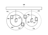
- FIG. 1 is a diagram illustrating a configuration example of a wireless communication system.
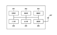
- FIG. 2 is a diagram illustrating a hardware configuration example of a communication device.
- FIG. 3 is a diagram illustrating a functional configuration example of an access point;
- FIG. 4 is a diagram showing a functional configuration example of a station.
- FIG. 5 is a diagram illustrating an example of communication flow in a wireless communication system.
- FIG. 6A is a diagram illustrating an example of interference avoidance adjustment.
- FIG. 6B is a diagram illustrating an example of interference avoidance adjustment.
- FIG. 6A is a diagram illustrating an example of interference avoidance adjustment.
- FIG. 6C is a diagram illustrating an example of interference avoidance adjustment.
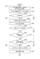
- FIG. 7A is a diagram illustrating an example of a flow of processing performed by a communication device;
- FIG. 7B is a diagram illustrating an example of the flow of processing performed by a communication device;
- FIG. 7C is a diagram illustrating an example of a flow of processing performed by a communication device;
- FIG. 8A is a diagram explaining the configuration of the MAC frame format.
- FIG. 8B is a diagram explaining the configuration of the MAC frame format.
- FIG. 8C is a diagram explaining the configuration of the MAC frame format.
- FIG. 9 is a diagram for explaining the structure of the HT Control field format.
- FIG. 10A is a diagram explaining the configuration of a trigger frame.
- FIG. 10A is a diagram explaining the configuration of a trigger frame.
- FIG. 10B is a diagram explaining the configuration of a trigger frame.
- FIG. 10C is a diagram explaining the configuration of a trigger frame.
- FIG. 10D is a diagram explaining the configuration of a trigger frame.
- FIG. 10E is a diagram explaining the configuration of a trigger frame.
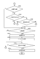
- FIG. 11 is a diagram illustrating an example of communication flow in a wireless communication system.
- This wireless communication system is a wireless communication system in which access points (APs) each configure a network and communicate with connected stations (STAs) via a wireless LAN conforming to the IEEE802.11 standard series, for example. is. Although only two APs (AP101, AP106) are shown in FIG. 1, there may naturally be three or more APs, and the number of APs may be one. Two or more APs can communicate with each other via the backhaul network 100 . In addition, although four STAs (STA 102, STA 103, STA 107, and STA 108) are shown in FIG. good.
- STA 102 and STA 103 are currently connected to AP 101 and are communication partner devices of AP 101 . It is also assumed that STA 107 and STA 108 are currently connected to AP 106 and are communication partner devices of AP 106 . It should be noted that the AP and STA merely indicate that they operate as a wireless LAN base station and terminal, respectively, and can be any communication device that can operate as both an AP and an STA, for example. .
- the backhaul network 100 can be configured by, for example, a wired communication line such as Ethernet (registered trademark) or a telephone line, but is not limited to this.
- the backhaul network 100 may be configured by a wireless communication line, or may be configured by a combination of a wireless communication line and a wired communication line.
- the wireless communication line can be, for example, a wireless communication line by a cellular communication network such as LTE (Long Term Evolution) or fifth generation (5G).
- the wireless communication line may be a wireless communication line based on other wireless communication standards such as WiMAX (Worldwide Interoperability for Microwave Access) and IEEE802.11 standard series.
- the backhaul network 100 can be used to interconnect the BSS (Basic Service Set) of the AP and other networks when the AP builds a DS (Distributions System).
- BSS Basic Service Set
- DS Distributions System
- the AP 101 configures and manages a first network (first BSS) that provides communication services to STAs existing in the area 104 .
- AP 106 configures and manages a second network (second BSS) that provides communication services to STAs existing in area 109 .
- Area 105 indicates a range in which communications of the first BSS are free from interference from APs and STAs belonging to other BSSs (eg, the second BSS).
- An area 110 indicates a range in which the communication of the second BSS is free from interference from APs and STAs belonging to other BSSs (for example, the first BSS).
- an area of the area 104 that is not included in the area 105 is capable of communication of the first BSS, but is subject to interference from communication of APs or STAs belonging to other BSSs, or This is an area that can interfere with STA communications.
- areas of area 109 that are not included in area 110 are capable of communication of the second BSS, but are subject to interference from communications of APs or STAs belonging to other BSSs, or This is an area that can interfere with STA communications.
- both AP 101 and AP 106 are assumed to have a Multi-AP Coordination configuration function.
- the Multi-AP Coordination function is a function that cooperates with other APs to provide communication to STAs that are currently connected, and provides faster communication than communication by only one AP or communication in a better communication environment.
- the Multi-AP Coordination function indicates a communication environment with a higher signal-to-noise ratio, less interference, less communication delay, less jitter, etc. compared to when communication is provided by only one AP. Any of the indicators can be improved.
- Such a communication method is, for example, JTX (Joint Transmission) using D-MIMO (Distributed Multiple Input Multiple Output).
- D-MIMO is MIMO that transmits and receives signals in parallel over geographically distributed antennas (APs).
- APs geographically distributed antennas
- DL downlink
- the null antenna weight is adjusted based on the information indicating the state of the transmission path between the AP and the STA so that the signal does not reach a specific STA during communication. There is steering.
- Coordinated OFDMA and Fractional Coordinated OFDMA exist as one of such communication techniques. These will be described later. Coordinated OFDMA is hereinafter referred to as "C-OFDMA", and Fractional Coordinated OFDMA is referred to as "FC-OFDMA”. Moreover, when C-OFDMA and FC-OFDMA are not particularly distinguished, they may simply be referred to as C-OFDMA. Note that if the Multi-AP Coordination configuration function is not executed, AP 101 manages only the first BSS and AP 106 manages only the second BSS. Here, “management” mainly refers to resource allocation of OFDMA and management of timing of its communication.
- the AP notifies the STA that there is no need to perform carrier sensing in an environment where it is assumed that no interference will occur.
- AP 101 can create an environment in which STA 102 and STA 103 do not need to perform carrier sensing by coordinating with AP 106 using the Multi-AP Coordination function so that mutual interference does not occur. Then, in this case, AP 101 transmits information indicating that it is not necessary to perform carrier sensing to STA 102 and STA 103, and STA 102 and STA 103 transmit uplink (UL) signals to AP 101 without performing carrier sensing. Send.
- the uplink is the link used to transmit signals from the terminal to the base station (ie, STA to AP).
- the link used to transmit signals from the AP to the STAs is called downlink (DL).
- AP 106 also transmits to STA 107 and STA 108 information indicating that it is not necessary to perform carrier sensing, and STA 107 and STA 108 transmit UL signals to AP 101 without performing carrier sensing.
- the AP can notify the STA that it does not need to perform carrier sensing even if it knows that there are no other BSSs in the vicinity, for example.
- the network is configured such that only one AP is provided in a limited area and other AP's communications do not interfere with the one AP's communications, the impact of interference is considered. There is no need to do so.
- the AP can perform carrier sense for the STAs being connected even if cooperative operation with other APs is not performed. You can notify that it is unnecessary.
- the AP confirms that other APs do not exist in the vicinity, or obtains information such as that other APs in the vicinity have stopped communication, and interferes. You may recognize that it is an environment in which
- the communication device has a storage unit 201, a control unit 202, a function unit 203, an input unit 204, an output unit 205, a communication unit 206, and an antenna 207 as an example of its hardware configuration.
- the storage unit 201 is composed of one or more memories including both or either one of ROM and RAM, and stores programs for performing various operations described later and various information such as communication parameters for wireless communication.
- ROM is an acronym for Read Only Memory
- RAM is an acronym for Random Access Memory.
- storage media such as flexible disks, hard disks, optical disks, magneto-optical disks, CD-ROMs, CD-Rs, magnetic tapes, non-volatile memory cards, and DVDs are used.
- the storage unit 201 may be configured to include storage devices such as a plurality of memories.
- the control unit 202 is composed of, for example, one or more processors such as CPU and MPU, ASIC (Application Specific Integrated Circuit), DSP (Digital Signal Processor), FPGA (Field Programmable Gate Array), and the like.
- CPU is an acronym for Central Processing Unit
- MPU is an acronym for Micro Processing Unit.
- the control unit 202 may be a multi-core processor.
- a control unit 202 controls the entire apparatus by executing a program stored in the storage unit 201 .
- the control unit 202 may control the entire apparatus through cooperation between the program stored in the storage unit 201 and an OS (Operating System).
- control unit 202 controls the function unit 203 to perform predetermined processing such as imaging, printing, and projection.
- the functional unit 203 is hardware for the device to execute predetermined processing.
- the functional unit 203 is an imaging unit and performs imaging processing.
- the functional unit 203 is a printing unit and performs print processing.
- the functional unit 203 is a projection unit and performs projection processing.
- the data processed by the function unit 203 may be data stored in the storage unit 201, or may be data communicated with another AP or STA via the communication unit 206, which will be described later.
- the function unit 203 may include a processing circuit for realizing the AP function and the STA function. may be configured to perform
- the input unit 204 receives various operations from the user.
- the output unit 205 performs various outputs to the user.
- the output from the output unit 205 includes, for example, at least one of display on a screen, audio output from a speaker, vibration output, and the like.
- both the input unit 204 and the output unit 205 may be realized by one module like a touch panel.
- the communication unit 206 controls wireless communication conforming to the IEEE802.11 standard series and IP communication.
- the communication unit 206 is a so-called wireless chip, and may itself include one or more processors and memories. In this embodiment, the communication unit 206 is capable of executing processing complying with at least the IEEE802.11be standard.
- the communication unit 206 controls the antenna 207 to transmit and receive radio signals for wireless communication.
- the AP and STA communicate content such as image data, document data, and video data with other communication devices via the communication unit 206 .
- the antenna 207 is, for example, an antenna capable of transmitting and receiving at least one of the sub-GHz band, 2.4 GHz band, 5 GHz band, and 6 GHz band.
- Antenna 207 may be a single antenna or a set of two or more antennas for MIMO (Multi-Input and Multi-Output) transmission and reception. Also, the antenna 207 may include two or more (two or more sets) of antennas each capable of corresponding to a different frequency band.
- the communication unit 206 has a Multi-AP Coordination function. Although one communication unit 206 and one antenna 207 are shown in FIG. 2, a plurality of combinations thereof may be prepared. Also, one or more antennas 207 may be shared by a plurality of communication units 206 .
- the AP has, for example, a wireless LAN control section 301, a UI control section 302, a storage control section 303, a cooperative operation method selection section 304, and a Single-AP configuration control section 305.
- the AP also has a JTX configuration control unit 306 , a null steering configuration control unit 307 , a C-OFDMA configuration control unit 308 , an FC-OFDMA configuration control unit 309 and a schedule adjustment configuration control unit 310 .
- these functions can be realized, for example, by the control unit 202 executing a program stored in the storage unit 201 (in one example, by the control unit 202 controlling the communication unit 206).
- the wireless LAN control unit 301 performs control for transmitting and receiving wireless signals with other communication devices (for example, other APs and STAs) according to the wireless LAN standard. That is, the wireless LAN control unit 301 generates and transmits wireless frames containing control information and data to be transmitted, and receives wireless frames from other communication devices, according to the IEEE802.11 standard series. Execute communication control.
- a UI control unit 302 detects an operation of a user interface (UI) such as a touch panel or buttons by a user (not shown) of the AP, and performs processing such as converting the detected operation into data that can be used inside the AP. .
- the UI control unit 302 also has functions for presenting information to the user, such as image display and audio output.
- the storage control unit 303 controls the storage unit 201 to store information about processing executed by the AP, and controls reading of data stored in the storage unit 201 .
- Cooperative operation method selection section 304 determines whether or not another AP exists within a predetermined range in which cooperative operation is possible, capability information of other APs, information indicating the connection state between other APs and STAs, and the like. Based on this, the method of the Multi-AP Coordination function to be used is selected.
- the Single-AP configuration control section 305 executes control when the Multi-AP Coordinate function is not operated, that is, when the AP communicates with the STA alone.
- the JTX configuration control unit 306, null steering configuration control unit 307, C-OFDMA configuration control unit 308, and FC-OFDMA configuration control unit 309 are functional units for executing their respective Multi-AP Coordinate functions. That is, the JTX configuration control unit 306, for example, performs control for executing JTX using D-MIMO, and the null steering configuration control unit 307 performs control for executing null steering. In addition, C-OFDMA configuration control section 308 and FC-OFDMA configuration control section 309 perform control for executing C-OFDMA and FC-OFDMA, respectively.
- the schedule adjustment configuration control unit 310 schedules the operation of the Multi-AP Coordinated function.
- FIG. 4 shows an example of the functional configuration of STAs (STA 102, STA 103, STA 107, STA 108).
- the STA has, for example, a wireless LAN control section 401, a UI control section 402, a storage control section 403, and a carrier sense control section 404.
- FIG. Note that these functions can be realized, for example, by the control unit 202 executing a program stored in the storage unit 201 (in one example, by the control unit 202 controlling the communication unit 206).
- a wireless LAN control unit 401, a UI control unit 402, and a memory control unit 403 are the same as the corresponding functional units of the AP (wireless LAN control unit 301, UI control unit 302, and memory control unit 303).
- Carrier sense control section 404 determines whether or not carrier sense is necessary in the radio frame received from the AP, and controls whether or not to execute carrier sense based on the determination result. For example, when determining that carrier sensing is unnecessary, the carrier sense control unit 404 can control the wireless LAN control unit 401 to transmit UL wireless frames without performing carrier sensing. Further, for example, when determining that carrier sense is necessary, the carrier sense control unit 404 can control the wireless LAN control unit 401 to perform carrier sense before transmitting the UL radio frame.
- FIG. 5 illustrates an example communication flow performed in a wireless communication system.
- connections are established between the AP 101 and the STAs 102 and 103 (S501, S502).
- the AP and STA exchange management frames containing information elements (IEs) indicating mutual capability information and operational information.
- the Management frame is, for example, Beacon, Probe Request/Response, Association Request/Response, or Authentication Request/Response.
- the AP 101 sets an Association ID for each of the STA 102 and STA 103 in connection processing. This ID is used as an STA ID for identifying each STA in a TF (trigger frame) described later.
- This IE is, for example, the HT Capability element in the IEEE802.11n standard, and the VHT Capability element in the IEEE802.11ac standard.
- This IE indicates, for example, whether the IEEE802.11ax standard supports BQR (Bandwidth Query Report). This is indicated by 1 bit in the "BQR Support" subfield included in HE MAC Capabilities.
- the AP By setting this bit to '1', the AP indicates that it can receive a BQR from the terminal, and the STA generates a BQR by setting this bit to '1', and the AP Indicates that it is possible to notify to Also, the compatibility with Multi-AP introduced from the IEEE802.11be standard is notified by the EHT Capabilities element.
- AP 101 While connected to STA 102 and STA 103, AP 101 transmits BSRP (BSR Poll) TF for requesting BSR (Buffer Status Report) to these STAs (S503). Then, STA 102 and STA 103 transmit BSR indicating the amount of data retained in the transmission buffer to AP 101 according to BSRP TF (S504). Thereafter, AP 101 transmits BQRP (BQR Poll) TF for reporting BQR indicating channel availability to STA 102 and STA 103 (S505). Then, STA 102 and STA 103 transmit BQR to AP 102 according to this BQRP TF (S506). Note that the processes from S501 to S506 described later are similarly executed between the AP 106 and the STAs 107 and 108 .
- AP 101 executes a multi-AP configuration setup procedure with AP 106 (S507).
- This procedure includes negotiation to determine which of AP 101 and AP 106 will act as the Master AP (and which will act as the Slave AP).
- the Master AP is an AP that operates in the role of controlling the entire Multi-AP configuration, and operates to determine the RU and timing that each AP should use.
- the Master AP can be called a Coordinator AP or a Sharing AP.
- Slave APs can be called Coordinated APs or Shared APs. In this example, it is assumed that AP 101 has been determined to operate as the Master AP.
- the AP 101 and AP 106 execute interference avoidance adjustment processing (S508).
- this adjustment will be described with reference to FIGS. 6A to 6C.
- FIGS. 6A to 6C the horizontal axis indicates time and the vertical axis indicates frequency.
- FIGS. 6A to 6C schematically show frequencies and times, and specific time lengths, time units, frequency bandwidths, and frequency units are not particularly limited.
- the length of time and the unit of time may vary depending on the use case of the Multi-AP Coordination configuration. For example, from the TU (Time Unit, 1024 microseconds) of the IEEE802.11 standard series, milliseconds, seconds, or more numerical values and units related to human sensitivity and operation are used as units of time length and time. sell.
- the unit of frequency bandwidth and frequency can be, for example, an OFDMA RU (Resource Unit) defined by the IEEE 802.11ax standard.
- a multi-band band or multi-channel 20 MHz unit channel may be used as the frequency unit.
- solid-line rectangles indicate time/frequency resources used by AP 101 (first BSS)
- dashed-line rectangles indicate time/frequency resources used by AP 106 (second BSS).
- An interference limited terminal is also called an interference limited STA, and refers to a STA that is affected by communication in a BSS to which its own device does not belong.
- SAT 103 and STA 108 are interference limited terminals.
- a STA that is not affected by communications of other BSSs is called a non-interference limited STA.
- STA 102 and STA 107 are non-interference limited terminals.
- An interference-limited terminal may be called an edge terminal (edge STA), and a non-interference-limited terminal may be called a center terminal (center STA).
- FIG. 6A is a diagram explaining the C-OFDMA method.
- the available frequency resources RUs
- APs and STAs the available frequency resources
- the RUs used in the first communication between AP101 and STA102 and STA103 do not overlap the RUs used in the second communication between AP106 and STA107 and STA108 in the frequency domain.
- C-OFDMA separates the frequency resources available in each BSS so that they do not overlap each other, so it is possible to prevent mutual interference between communications between BSSs. That is, when C-OFDMA is used, communication between AP101 and STA102 and STA103 can be prevented from interfering with communication between AP106 and STA107 and STA108.
- FC-OFDMA allows the RUs used among multiple BSSs to overlap in the frequency domain.
- the overlapping frequency region is used for communication of STAs located near the AP, for example, so that interference between BSSs can be prevented.
- the AP 101 can receive the radio frame even if the STA 102 transmits the radio frame with low power. It is also assumed that such radio frames will never reach AP 106, STA 107, and STA 108 with sufficient power. Also, it is assumed that the radio frame transmitted by STA 107 with low power will not reach AP 101, STA 102, and STA 103 with sufficient power.
- FC-OFDMA ensures that even if the same frequency and time resources are used by multiple BSSs, interference will only occur at a sufficiently low power level compared to the power of the signal within the BSS. , can be said to be an interference avoidance scheme in the power axis.
- FIG. 6B shows an example in which the first BSS and the second BSS share the entire frequency resource, only part of the frequency resource may be shared.
- FIG. 6C shows an example of dividing resources in the time domain.
- the first BSS and the second BSS are coordinated to use different time resources. According to this, communication is not performed on the second BSS while the first BSS is communicating, and communication is not performed on the first BSS while the second BSS is communicating. Interference between them can be prevented.
- the type of interference avoidance is determined as to whether interference is to be avoided (suppressed) in any of the frequency, power, and time domains. Note that these are only examples, and interference avoidance may be performed in other areas (for example, code, space, etc.). At this point, processing for interference avoidance control is performed among the communication devices (AP 101, STA 102, STA 103, AP 106, STA 107, STA 108) as necessary.
- a process is performed to identify whether the In one example, a predetermined radio frame transmitted by an AP is measured by another AP or STA, and the STA notifies the connected AP of the measurement result.
- STA 102 and STA 103, AP 106, STA 107 and STA 108 measure a predetermined radio frame transmitted by AP 101.
- STA 102 and STA 103 report measurement results to AP 101
- STA 107 and STA 108 report measurement results to AP 102.
- AP 101, STA 102 and STA 103, STA 107 and STA 108 measure a predetermined radio frame transmitted by AP 106.
- STA 102 and STA 103 report measurement results to AP 101
- STA 107 and STA 108 report measurement results to AP 102.
- FIG. This identifies "how the frame from the AP was received by other APs and STAs".
- power-based interference avoidance control such as FC-OFDMA
- AP 101 and AP 106 may share this identified result and use it for subsequent interference avoidance processing.
- each AP may measure frames from each STA and share the results as well.
- AP 101 transmits a Multi-AP TF to AP 106 (S509).
- the Multi-AP TF will be described later.
- AP 101 has decided to perform interference avoidance control in the frequency domain with AP 106 .
- the Multi-AP TF transmitted by AP101 includes information indicating that interference avoidance control should be performed in the frequency domain and information indicating available frequency resources in AP106.
- AP 101 transmits Basic TF to STA 102 and STA 103 (S510), and AP 106 transmits Basic TF to STA 107 and STA 108 (S511).
- AP 101 determines frequency resources to allocate to STA 102 and STA 103 from, for example, second frequency resources different from the first frequency resources allocated to AP 106 in the Multi-AP TF.
- AP 106 determines frequency resources to allocate to STA 107 and STA 108 from among the first frequency resources specified in the Multi-AP TF. Note that the AP 101 and AP 106 set the CS Required bit of the Common field of the Basic TF according to the result of the interference avoidance adjustment processing in S508.
- This bit indicates whether or not the STA that will transmit the radio frame with the TF needs to perform carrier sense. For example, when the CS Required bit is "0", it indicates that carrier sensing is unnecessary.
- AP 101 and AP 106 transmit Basic TF with this bit set to '0' when interference avoidance coordination can be performed.
- the second frequency resource is used for signal transmission to AP 101 and the first frequency resource is used for signal transmission to AP 106, so that an environment in which there is no mutual interference can be obtained. . Therefore, AP101 and AP106 can notify the STA that carrier sensing is not required by the CS Required bit set in the TF.
- STA 102 and STA 103 Upon receiving the Basic TF from AP 101, STA 102 and STA 103 transmit TB PPDU (Trigger Based Physical layer Protocol Data Unit) to AP 101 (S512). Also, upon receiving the Basic TF from AP 106, STA 107 and STA 108 transmit TB PPDU to AP 106 (S513). Data to be transmitted from each STA to the AP is transmitted by the TB PPDU. Thereafter, AP 101 transmits Multi-STA BA (Block Ack) to STA 102 and STA 103 (S514), and AP 106 transmits Multi-STA BA to STA 107 and STA 108 (S515).
- TB PPDU Trigger Based Physical layer Protocol Data Unit
- the AP 106 can prompt the source of the data to resend the data (not shown).
- the AP 106 can prompt data retransmission by not transmitting NACK or ACK when a Hybrid Automatic Repeat reQuest (HARQ) procedure is adopted.
- the AP 106 may also prompt retransmission of data by sending BlockAck with BlockAck Bitmap not set.
- FIGS. 7A to 7C The processing of FIGS. 7A to 7C is implemented by executing a program stored in the storage unit 201 by the control unit 202 of the AP, for example. Note that at least part of the following processing may be realized by dedicated hardware. It is assumed that the AP has completed various settings such as settings related to BSS operation, enable/disable settings for Multi-AP operation related to this embodiment, and settings for TF transmission conditions. It is also assumed that AP 101 has established connections (association procedures have been completed) with STA 102 and STA 103 . Similarly, it is assumed that AP 106 has established connections with STA 107 and STA 108 .
- STA capabilities include an item called "absolute transmission power accuracy" that indicates the accuracy of transmission power adjustment. This value classifies the device class. Terminals with absolute transmission power accuracy of ⁇ 3 dB are classified as Class A device class. On the other hand, a terminal with absolute transmission power accuracy of ⁇ 9 dB is classified as Class B in device class. This information can be used, for example, to determine whether interference avoidance control in the power domain is possible.
- the AP transmits a TF for inquiring communication characteristics to the STAs currently connected (S701), and receives information on communication characteristics from each STA as a response to the TF (S702).
- the communication characteristics here are information indicating traffic characteristics, and BSR is used as an example.
- the BSR is included in the Control subfield of a MAC (Medium Access Control) frame, which will be described later, and is used for notifying the amount of data for each access category held in the transmission buffer by the STA.
- the communication characteristic inquiry may be a TSPEC (traffic specification) inquiry.
- TSPEC can specify the maximum and minimum values of Service Interval, Service Start Time, minimum Data Rate, Burst Size, and the like.
- Service Interval is information that can specify the time between two service periods that are not interposed by another service period.
- Service Start Time is information that can specify the time when the first service period of the service starts.
- Data Rate indicates the communication speed
- Burst Size indicates the burst size of data to be transmitted.
- the AP determines whether or not to take the lead in executing UL communication (S703).
- the AP instructs the STA to transmit data using the TF.
- the AP can determine not to execute UL communication led by its own device.
- the AP can determine to perform UL communication when multiple STAs hold data to be transmitted.
- the AP takes the lead when instructing the transmission of the data to that STA by the TF. It determines to execute UL communication. If the AP determines that it will take the lead in executing UL communication (YES in S703), it moves the process to S704; to S726.
- the AP 101 transmits a TF (BQRP TF) for inquiring about the BQR to each STA, and then receives the BQR from each STA as a response (S705).
- BQRP TF TF
- the BQR is notified using the Control subfield of the MAC frame described later, and is used to notify information indicating whether or not the channel operated by the BSS can be used in units of 20 MHz. That is, the BQR indicates with at least 1 bit whether the 20 MHz partial frequency band included in the channel being operated by the BSS is available (busy or not available).
- the maximum frequency bandwidth that a BSS can operate is 320 MHz, so the BQR length can be 16 bits (2 octets) or more.
- the STA can determine the availability of each partial frequency band based on the state when the BQRP TF is received, it is not limited to this. For example, the STA may determine the availability of each partial frequency band based on the ratio of busy or not available from the previous reception of the BQRP TF to the current reception of the BQRP TF.
- the AP determines whether all channels in operation are available based on the received BQR (S706). If all channels in operation are available (YES in S706), the AP advances the process to S713. Note that in this case it is assumed that there are no other BSSs interfering with the BSS being formed by the AP. On the other hand, if at least part of the channels in operation are not available (NO in S706), the AP then determines whether the unavailable (busy or not available) channels are being used by the wireless LAN. is determined (S707).
- the AP for example, by receiving a notification of the detection result of the wireless LAN signal from the STA, or by detecting the signal of another BSS by itself or knowing in advance the information of other APs in the vicinity This determination is made based on Note that the AP may receive the notification of the wireless LAN signal detection result from the STA, for example, in S705 using the BQR supplementary information notification procedure.
- the supplementary information can indicate information of the BSS that uses the channel (for example, information that associates the BSSID with the channel) when the channel state in units of 20 MHz is busy. This information can be communicated by the contents of the new Action Frame and Data Frame in the IEEE802.11 standard.
- the AP determines whether communication with the AP of that BSS is possible using a multi-AP configuration (S708). Then, when the AP determines that it is possible to communicate with other APs using the channel using the Multi-AP configuration (YES in S708), the AP executes Multi-AP setup processing with that AP. (S709). In the Multi-AP setup process, the AP searches for other APs that can cooperate in the Multi-AP configuration and determines Master AP and Slave AP.
- APs can cooperate in a Multi-AP configuration, for example, by receiving a Beacon containing information indicating that they have Multi-AP capability or are operating in Multi-AP. Other APs can be searched. Also, the AP may identify other APs with which it can cooperate in a multi-AP configuration by checking setting information by the user or the like. On the other hand, if the unavailable channel is not used by another BSS in the wireless LAN (NO in S707), or if communication with other APs using the channel using the Multi-AP configuration is not possible (in S708 NO), the AP advances the process to S715. That is, if the adjustment by the AP cannot be performed, the process proceeds to S715. Note that the AP may prompt the user to change the channel to be operated to another channel at this point, and advance the process to S720.
- the AP exchanges information indicating the type of control that can be adjusted with the other APs that make up the multi-AP (S710).
- Information indicating the type of control that can be adjusted is, for example, as described with reference to FIGS. Possible.
- Interference avoidance control in the frequency domain can be used depending on whether it is necessary to avoid a specific channel in communication or whether communication is possible on any channel. If communication is possible on any channel, it is determined that interference avoidance control in the frequency domain is possible, and if it is necessary to avoid a specific channel, it is determined that interference avoidance control in the frequency domain is not possible. can be judged. For example, in a channel where radar exists, it is necessary to move the channel after radar detection and monitor for a specified time, but if the communication characteristics of the STA do not allow such processing, avoid using that channel. It will be necessary to Therefore, in such a case, it is determined that adjustment in the frequency domain is not possible.
- Whether or not interference avoidance control in the time domain can be used is determined based on the periodicity of communication and the allowable delay. For example, performing interference avoidance control in the time domain generates a period during which communication cannot be performed, but if the communication characteristics of the STA cannot allow this, it is determined that adjustment in the time domain is not possible.
- the availability of interference avoidance control in the power domain can be determined based on the device classes of APs and STAs.
- the AP specifies the transmission power of the STA by transmitting a TF in which the value of UL Target receiver power in the User Info field is set.
- the permissible interference level is notified to other BSSs, and multiple BSSs performing multi-AP communication control mutual transmission power. For this reason, the AP designates the received power value that should be achieved in its own device without interfering with other BSSs as the UL Target receiver power. It is assumed that the range of transmission power values satisfying such conditions has a certain width.
- the AP determines whether there is a control type that can be used in common with other APs that exchanged information on the types of interference avoidance control that can be performed in the multi-AP configuration in S710.
- the AP determines the adjustment type, and selects the determined adjustment type. It is shared between APs (S712).
- the AP for example, both the frequency domain and the time domain, or a combination of at least one of the frequency domain and the time domain and the power domain, if control in a plurality of types is possible, in any combination It may be determined to perform interference avoidance control.
- the AP sets the "CS Required bit” in the TF transmitted in the process described later to "0" (S713).
- This "CS Required bit” is a bit indicating whether or not carrier sense is required, "0" indicates that carrier sense is not required, and "1" indicates that carrier sense is required.
- interference avoidance control can be performed in either the frequency or time domain between BSSs, and in order to notify the STA that carrier sensing is not required, the TF with this bit set to "0" is set to the STA. to be sent to
- the AP determines whether or not interference avoidance control is possible in the power domain (S714).
- the AP determines that interference avoidance control in the power domain is possible (YES in S714)
- the AP determines to use interference avoidance control in the power domain (S712), and sets "CS Required bit” in TF to "0". (S713).
- the AP determines that interference avoidance control in the power domain is not possible (YES in S714), it sets the "CS Required bit" in the TF to "1" (S715).
- the STA when it is determined that interference avoidance control cannot be performed between BSSs, the STA is notified that carrier sensing should be performed and signals should be transmitted.
- the determination of S714 may be performed at the same time as S711. However, as described above, some kind of sounding process is required to determine whether interference avoidance control based on power is possible. Therefore, the sounding process may be performed in parallel with the determination of S711, and the determination of S714 may be performed after the determination of S711, as shown in FIGS. 7A to 7C.
- interference avoidance control in the power domain cannot sufficiently avoid interference compared to interference avoidance control in the frequency domain or time domain, such as abrupt changes due to changes in the communication environment.
- interference avoidance control in the frequency domain or time domain when interference avoidance control in the frequency domain or time domain can be performed, those interference avoidance controls are used, and as shown in FIGS. Only the applicability of interference avoidance control in the power domain may be determined. Note that the sounding process may be performed in advance so that the determination of S714 can also be performed at the time of the process of S711. In this case, if the AP can perform interference avoidance control between BSSs in some way, the process proceeds to S712, and if such interference avoidance control cannot be performed, the process proceeds to S715. may be moved.
- the AP determines that carrier sense is unnecessary when interference avoidance control is performed in the frequency domain or time domain, and carrier sense is required when only interference avoidance control in the power domain is performed. It may be determined that there is That is, the AP may determine whether or not carrier sensing is necessary depending on whether the type of interference avoidance control that can be executed is a predetermined type.
- Multi-AP TF is an extension of TF in the IEEE802.11ax standard and is used to allocate OFDMA RUs or channels in units of 20 MHz to APs rather than STAs.
- the frame configuration of the Multi-AP TF will be described later using FIGS. 10A to 10E.
- the AP determines allocation of RUs for UL communication to STAs within the range of RUs or channels specified by the Multi-AP TF (S719), and assigns TF is transmitted (S720).
- the value of the "CS Required bit" set in S714 or S715 described above is set in the common field of the TF sent here.
- the UL Length value in this TF is determined based on the Duration value specified in the Multi-AP TF.
- the AP then transmits an acknowledgment (ACK) to the STA that sent the TB PPDU (S722).
- ACK acknowledgment
- the STA can recognize that there is no need to perform carrier sensing.
- the STA can recognize that carrier sensing should be performed.
- the AP determines whether or not to continue UL communication (S723).
- the AP determines whether to inquire about the channel state (S724). For example, the AP determines the channel state based on at least one of the following conditions: that the AP itself has detected a change in the wireless medium, that a predetermined time has passed since the previous BQR inquiry, or that an unsolicited BQR has been received from the STA. You can find out by asking.
- An unsolicited BQR is a BQR spontaneously transmitted by a STA that has not received a BQRP TF from the AP.
- the STA can include the BQR in the Control subfield of the MAC frame, which will be described later, and transmit it.
- the MAC frame can be included in the TB PPDU transmitted from the STA in S721, or included in the radio frame during communication transmitted without using the TF by EDCA (Enhanced Distributed Channel Access).
- EDCA Enhanced Distributed Channel Access
- the STA may notify the AP of the BSR by an unsolicited method that does not depend on the TF.
- the process returns to S704.
- the AP determines whether or not to maintain the interference avoidance control for the type (for example, determined in S712) (S725). Then, if the AP maintains the type of interference avoidance control (YES in S725), the process returns to S716, and if not (NO in S725), the process returns to S709.
- the AP must maintain the type of interference avoidance control according to, for example, changes in the status of the BSS formed by other APs that are counterpart devices in the Multi-AP configuration and the BSS formed by the own device, activation of different BSSs, and the like. can decide. This allows the AP to re-execute the multi-AP setup and re-select the appropriate type of interference avoidance control.
- the AP determines not to continue UL communication (YES in S723), it determines whether to execute DL communication (S726). Then, when the AP determines to perform DL communication (YES in S726), it transmits PPDU to one or more STAs.
- the AP uses MU (Multi User) PPDU when transmitting data to multiple STAs at once, and SU (Single User) PPDU when transmitting data to a single STA. can be used. Note that the AP may perform sounding for MIMO or inquire of the STA about the BQR as necessary during the DL communication.
- the AP After transmitting the PPDU, the AP receives an acknowledgment (ACK) from the STA that is the destination of the PPDU (S728).
- ACK acknowledgment
- the AP can resend data to the STA when detecting a reception failure at the STA (not shown).
- the AP can detect a reception failure by, for example, receiving a NACK when a HARQ (Hybrid Automatic Repeat Quest) procedure is adopted, or by not receiving an ACK.
- the AP may detect a reception failure based on receiving a BlockAck in which the BlockAck Bitmap is not set. After that, the AP returns the process to S726 and determines whether to continue the DL communication.
- the AP determines whether to change the operation of the AP (S729). For example, the AP determines whether it has received a user operation to change settings such as enabling/disabling of the Multi-AP operation. Note that the AP may move the process to S729 when accepting a setting change operation by the user at any stage during execution of the above process. That is, in the above example, the determination of S729 is performed after a series of communications including UL communication and DL communication is completed. You may move to S729. If the AP determines to change the operation (YES in S729), it changes the operation setting (S730) and ends the process.
- the AP may return the process to S701 after changing the operation setting. If the AP determines not to change the operation (NO in S729), it returns the process to S701 while maintaining the current settings.
- the STA when an AP can avoid interference between BSSs in advance by a Multi-AP configuration with other APs, the STA indicates that carrier sense is unnecessary. can be notified to Also, the AP can explicitly notify that carrier sensing is necessary in an environment where the STA should perform carrier sensing.
- the value of the "CS Required bit" is set based on whether or not the interference between APs can be adjusted, but the present invention is not limited to this.
- the AP may be configured to always set the "CS Required bit" to "0" when settings are made to indicate that the BSS formed by the AP should be given priority.
- the STA may be notified that carrier sensing is unnecessary in the BSS formed by the own device, regardless of whether or not coordination with other APs is possible.
- the AP may always set the "CS Required bit” to "1" to indicate that carrier sensing is required. These can be set, for example, by the user's operation of the AP.
- the "CS Required bit” may be set regardless of the interference avoidance control as described above. In addition, it may be indicated that carrier sense is required when the "CS Required bit” is "0", and that carrier sense is not required when the "CS Required bit” is "1".
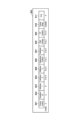
- FIG. 8A shows a configuration example of the entire MAC frame 800.
- Frame Control 801 is a field related to control of the entire frame and has a length of 2 octets (16 bits). Details of Frame Control 801 have subfields as described later with reference to FIG. 8B.
- Duration/ID 802 has a 2-octet length, and when the MSB (Most Significant Bits: B15) is "1", the remaining 15 bits indicate the frame length, TXOP, etc. time in the range of 0 to 32767 microseconds.
- Address 803 is a 6-octet length field, and addresses such as BSSID, source, and destination are set according to the MAC frame type (Type 822).
- Address 804, Address 805, and Address 807 are similar fields, but are set as required according to the number of addresses to be indicated.
- a Sequence Control 806 is a field set with a length of 2 octets as necessary to store information such as a data sequence number.
- the QoS Control 808 is a field set with a length of 2 octets as necessary to store information such as BSR (Buffer Status Report) of the standard prior to IEEE 802.11ax.
- BSR Buffer Status Report
- the BSR is represented by two pieces of information.
- the first of the two pieces of information is a 4-bit TID (Traffic Identifier).
- TID Traffic Identifier
- the values 0 to 7 among the values indicated by this TID correspond to the four access categories AC_VO (voice)/AC_VI (video)/AC_BE (best effort)/AC_BK (background). indicate either.
- the second information is an 8-bit queue size. Queue size is expressed in units of 256 octets and indicates the amount of data retained in the transmission buffer.
- HT Control 809 is a field set with a 4-octet length as needed.
- setting the leading 1 bit to "0" indicates that the frame is for HT (High Throughput: IEEE802.11n).
- setting the leading two bits to 10 indicates that the frame is for VHT (Very High Throughput: IEEE802.11ac).
- setting the leading two bits to 11 indicates that the frame is for HE (High Efficiency: IEEE802.11ax). It is undecided whether or not such a definition will be made for frames for EHT (Extremely High Throughput: IEEE802.11be).
- the Frame Body 810 is a field in which data to be transmitted is stored, and its length is variable according to the data length. As part of the Frame Body 810, an IE as shown in FIG. 8C can be stored.
- FCS 811 is a Frame Check Sequence and stores bits for error detection.
- Protocol Version 821 is a 2-bit subfield that indicates the version of the protocol, and is set to "0" in the case of IEEE802.11 frames.
- Type 822 is a 2-bit subfield indicating the frame type, and indicates whether the frame is a Management, Control, or Data frame.
- Subtype 823 is a 4-bit subfield that stores information for further classifying the types of Management, Control, and Data.
- To DS 824 is a 1-bit subfield indicating whether the destination of the frame is a DS (Distribution System). From DS 825 is a 1-bit subfield that indicates whether the source of the frame is DS.
- More Fragment 826 is a 1-bit subfield that indicates whether the frame is part of a fragment.
- Retry 827 is a 1-bit subfield indicating whether or not it is a retransmission of previously transmitted data.
- Power Management 828 is a 1-bit subfield indicating whether the STA is in power saving mode.
- More Data 829 is a 1-bit subfield that indicates whether there is more transmission data after the data transmitted in the current frame.
- Protected Frame 830 is a 1-bit subfield that indicates whether the frame is protected by encryption.
- +HTC 831 is a 1-bit subfield indicating whether HT Control 809 is included, for example.
- Element ID 841 stores the IE identifier.
- the IEEE802.11be EHT value follows the HE Capabilities element value of IEEE802.11ax and is set to 255, for example.
- Length 842 indicates the length of this information element.
- the Element ID Extension 843 stores an IE identifier that is set as needed. For example, in this embodiment, values corresponding to the EHT Capabilities element regarding capability information and the EHT Operation element regarding operational information are newly defined. These values are stored in the Element ID Extension 843.
- the EHT MAC Capabilities Information 844 stores information about MAC layer capabilities.
- the EHT PHY Capabilities Information 845 stores information about physical layer (PHY) capabilities.
- the Supported EHT-MCS And NSS Set 846 stores values indicating supported modulation and coding schemes (MCS) and number of spatial streams (NSS).
- PPE Physical layer Packet Extension
- Thresholds 847 is optional information.
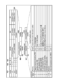
- the configuration of the HT Control 809 will be outlined using FIG.
- Variant 901 is the type of information. The type of information is determined by two bits (bit 902 and bit 903). In this embodiment, HE (High Efficiency: IEEE802.11ax) and EHT (Extremely High Throughput: IEEE802.11be) correspond to the same bit string "11". The definition for EHT is undecided.
- A-Control 904 is a 30-bit long field if the type is HE or EHT.
- A-Control 904 includes Control List 905 and Padding 906 . Control ID 907 indicates the type of Control List 905, and Control Information 908 indicates the content corresponding to that type.
- Control ID 907 For example, in the BSR of S702 of this embodiment, "3" is stored as Control ID 907, and 26-bit information is stored as Control Information 908. Also, in the BQR of S705, "5" is stored as the Control ID 907, and 10 or 16-bit information is stored as the Control Information 908. This 10- or 16-bit information indicates the channel status every 20 MHz. Note that this is an example, and the state of the channel may be indicated using more than 16 bits of information. The state of the channel may be indicated by one bit, for example idle or not available (busy, etc.). Note that the details of the unavailability may be further notified.
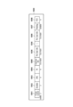
- the configuration of the Trigger Frame (TF1000) will be outlined using FIGS. 10A to 10E.
- the TF is a frame introduced from the IEEE802.11ax standard, and is a frame that indicates start timing and wireless channel information using the frame, which is necessary for multiple STAs (Users) to transmit frames to the AP in parallel. is.
- the Frame Control 1001 shown in FIG. 10A is a field common to the IEEE802.11 standard series, and contains, for example, a value indicating an IEEE802.11be Trigger Frame. The length of this field is 2 octets. Duration 1002 is a field indicating the time length of this frame, and its length is 2 octets. RA 1003 is a field indicating the address of the receiver (Receiver Address) and has a length of 6 octets. TA1004 is a field indicating the sender's address (Transmitter Address) and has a length of 6 octets.
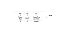
- Common Info 1005 is a field indicating information common to multiple terminals that are destinations of this TF, and has a length of 8 octets or more. Details of Common Info 1005 will be described later.
- Per User Info 1006 is a field indicating individual information for each destination of this TF, and a separate field is prepared for each destination. The length of each Per User Info 1006 is 5 octets or more.
- Padding 1007 is a field for giving time allowance to the terminal group that received this TF. The AP determines this time window based on each STA's MinTrigProcTime. Generally, the padding corresponding to the maximum value among the MinTrigProcTimes of the group of STAs to which the TF is addressed is used.
- FCS 1008 is a Frame Check Sequence and stores bits for error detection.
- Trigger Type 1011 is a subfield with a length of 4 bits, the details of which are shown in FIG. 10C, for example.
- Trigger Type 1011 value of "8" is prepared for the Multi-AP TF.
- Length 1012 stores the length corresponding to the type specified in Trigger Type 1011.
- Trigger Type dependent 1013 is a description corresponding to the type specified in Trigger Type 1011.
- the type 1031 stores information indicating the type of interference avoidance control to be used in the multi-AP configuration.
- the type 1031 can be expressed, for example, as 3-bit information indicating whether or not to use interference avoidance control in the frequency domain, time domain, and power domain with 1 bit each. For example, bit 0 indicates whether to use interference avoidance control in the frequency domain, bit 1 indicates whether to use interference avoidance control in the time domain, and bit 2 indicates whether to use interference avoidance control in the power domain. or not, respectively.
- a bit string “101” indicates that interference avoidance control is performed in the frequency domain and power domain.
- bit string "011” indicates that interference avoidance control is performed in the time domain and the power domain.
- bit string “111” indicates that interference avoidance control is performed in all of the frequency domain, time domain, and power domain. Note that this is just an example, and any bit string that can express possible combinations may be used, and a region of the number of bits corresponding to that bit string may be prepared as the type 1031 .
- Channel/RU 1032 is 1-bit information indicating whether to perform frequency division in a 20 MHz channel or to perform frequency division in RU units.
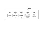
- BSSID 1041 is a field with a length of 48 bits for uniquely identifying the destination AP of the Multi-AP TF. For example, when AP101 transmits a Multi-AP TF to AP106, the identification information of AP106 is stored in BSSID1041.
- Start Time 1042 is a 64-bit long field that indicates the start time at which the BSS can use the channel or RU. This start time may be expressed, for example, by relative time from the transmission time of the Multi-AP TF, or by absolute time.
- Duration 1043 is a 32-bit long field that indicates how long the BSS can use the channel or RU.
- Channel/RU Allocation 1044 is a field that stores information indicating frequency resource allocation by channel or RU in units of 20 MHz. The details of IEEE 802.11be RU allocation are undecided, but in one example, it is similar to IEEE 802.11ax and Channel/RU Allocation 1044 can have a length of 9 bits or more.
- TPC Parameter 1045 sets a constraint value for transmission power control for STAs when interference avoidance control in the power domain is used.
- a new Multi-AP TF is defined, whereby the interference avoidance control to be executed can be shared between APs for communication. That is, for example, when performing interference avoidance control in the frequency domain, the AP transmits a Multi-AP TF in which the bit corresponding to the frequency domain in the type 1031 is set to "1" to other APs.
- the Channel/RU Allocation 1044 indicates frequency resources that can be used by the multi-AP transmission destination AP.
- the frequency resource is specified in units of 20 MHz when Channel is specified by Channel/RU 1032, and in units of RU when RU is specified.
- other APs are notified of information that enables execution of interference avoidance control in the frequency domain.
- the AP transmits a Multi-AP TF in which the bit corresponding to the time domain in type 1031 is set to "1" to other APs.
- Start Time 1042 and Duration 1043 indicate time resources that can be used by the destination AP of the Multi-AP.
- other APs are notified of information that enables execution of interference avoidance control in the time domain.
- the AP transmits a Multi-AP TF in which the bit corresponding to the power domain in the type 1031 is set to "1" to other APs.
- the TPC Parameter 1045 notifies the transmission power limit information to prevent the transmission signal of the STA connected to the transmission destination AP of the Multi-AP TF from interfering with the transmission source AP of the TF. be.
- the AP 101 notifies the AP 106 of information on performing interference avoidance control in the power domain and limiting the transmission power.
- This transmit power limit information may indicate, for example, the maximum transmit power that all STAs (eg, STA 107 and STA 108) connected to AP 106 should meet.
- AP 101 transmits to STA 102 and STA 103 a TF including information designating transmission power limits of STA 102 and STA 103 so that interference with AP 106 is sufficiently suppressed.
- AP 106 transmits to STA 107 and STA 108 a TF including information designating the transmission power limit of STA 107 and STA 108 based on the information stored in TPC Parameter 1045 from AP 101 .
- the STA transmission power limit is set by "UL Target receive power" included in Per User Info 1006 in Basic TF.
- a maximum value of transmission power may be specified for a specific STA. For example, since the STA 102 and STA 107 are located near the AP to which they are connected, even if the transmission power is suppressed, there is little impact on communication. Therefore, a Basic TF may be transmitted specifying these STAs and instructing them to lower their transmission power. Also, for example, it is possible to perform interference avoidance control in both the frequency domain and the time domain. In this case, for example, STA 102 and STA 107 may use the same frequency resource to perform UL communication with low transmission power, and STA 103 and STA 108 may be assigned different frequency resources. This also ensures that UL communications from STA 102 and STA 103 to AP 101 do not interfere with AP 106 and UL communications from STA 107 and STA 108 to AP 106 do not interfere with AP 101 .
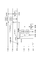
- the AP 101 executes interference avoidance adjustment with the AP 106 and determines to set interference avoidance control in the time domain (S1101).
- AP 101 determines the time resources used by AP 101 (first BSS) and AP 106 (second BSS). Then, the AP 101 sets a value indicating the time domain in the type 1031, and transmits to the AP 106 the Multi-AP TF specified by the Start Time 1042 and the Duration 1043 for the UL communication of the second BSS (S1102). .
- the timing at which the UL communication of the first BSS is started can be set to the timing after the SIFS (Short Inter Frame Space) has passed after the transmission of the Multi-AP TF. Also, the UL communication of the second BSS can be set at the timing when SIFS, the communication duration, and the transmission period of ACK have passed after the transmission of the Multi-AP TF, and SIFS has passed.
- SIFS Short Inter Frame Space
- the AP 101 transmits the Basic TF to the STAs 102 and 103 at the UL communication start timing of the first BSS (S1103).
- communication is not performed in the second BSS, and it is assumed that no interference will occur, so a Basic TF with the CS Required bit set to "0" is transmitted.
- the STA 102 and STA 103 recognize that carrier sense is not to be executed.
- STA 102 and STA 103 transmit TB PPDU to AP 101 according to TF (S1104), and AP 101 transmits ACK to STA 102 and STA 103 (S1105).
- the AP 106 waits for the Start Time 1042 specified in the TF from the transmission of the Multi-AP TF in S1102, and then transmits the Basic TF to the STAs 107 and 108 (S1106).
- the Basic TF with the CS Required bit set to "0" is transmitted.
- the STA 107 and STA 108 recognize that carrier sense is not to be executed.
- STA 107 and STA 108 transmit TB PPDU to AP 106 according to TF (S1107), and AP 106 transmits ACK to STA 107 and STA 108 (S1108).
- the second BSS may communicate first.
- communication may be performed without using the Basic TF in the first BSS or the second BSS. That is, UL communication by EDCA may be performed.
- DL communication may be performed. This is because adjustments are made so that other BSSs do not communicate during the set period.
- the AP can prevent degradation of frequency utilization efficiency due to carrier sensing by causing the STA to perform carrier sensing only when necessary (especially when operating in a multi-AP configuration). In addition, since unnecessary carrier sensing is not performed, it is possible to reduce the processing load on the STA and reduce its power consumption.
- the present invention supplies a program that implements one or more functions of the above-described embodiments to a system or device via a network or a storage medium, and one or more processors in the computer of the system or device reads and executes the program. It can also be realized by processing to It can also be implemented by a circuit (for example, ASIC) that implements one or more functions.
- a circuit for example, ASIC
Landscapes
- Engineering & Computer Science (AREA)
- Computer Networks & Wireless Communication (AREA)
- Signal Processing (AREA)
- Quality & Reliability (AREA)
- Mobile Radio Communication Systems (AREA)
Priority Applications (3)
| Application Number | Priority Date | Filing Date | Title |
|---|---|---|---|
| CN202280062052.4A CN117941452A (zh) | 2021-09-14 | 2022-08-25 | 接入点设备、通信方法、通信系统和程序 |
| EP22869768.6A EP4404674A4 (en) | 2021-09-14 | 2022-08-25 | ACCESS POINT (AP) DEVICE, COMMUNICATION METHOD AND SYSTEM, AND PROGRAM |
| US18/602,695 US20240251389A1 (en) | 2021-09-14 | 2024-03-12 | Access point apparatus, communication method, communication system, and computer-readable storage medium |
Applications Claiming Priority (2)
| Application Number | Priority Date | Filing Date | Title |
|---|---|---|---|
| JP2021149581A JP7846508B2 (ja) | 2021-09-14 | 2021-09-14 | アクセスポイント装置、通信方法、通信システム、及び、プログラム |
| JP2021-149581 | 2021-09-14 |
Related Child Applications (1)
| Application Number | Title | Priority Date | Filing Date |
|---|---|---|---|
| US18/602,695 Continuation US20240251389A1 (en) | 2021-09-14 | 2024-03-12 | Access point apparatus, communication method, communication system, and computer-readable storage medium |
Publications (1)
| Publication Number | Publication Date |
|---|---|
| WO2023042621A1 true WO2023042621A1 (ja) | 2023-03-23 |
Family
ID=85602147
Family Applications (1)
| Application Number | Title | Priority Date | Filing Date |
|---|---|---|---|
| PCT/JP2022/031986 Ceased WO2023042621A1 (ja) | 2021-09-14 | 2022-08-25 | アクセスポイント装置、通信方法、通信システム、及び、プログラム |
Country Status (5)
| Country | Link |
|---|---|
| US (1) | US20240251389A1 (https=) |
| EP (1) | EP4404674A4 (https=) |
| JP (1) | JP7846508B2 (https=) |
| CN (1) | CN117941452A (https=) |
| WO (1) | WO2023042621A1 (https=) |
Cited By (1)
| Publication number | Priority date | Publication date | Assignee | Title |
|---|---|---|---|---|
| EP4239994A1 (en) * | 2022-03-01 | 2023-09-06 | Canon Kabushiki Kaisha | Image forming apparatus, method, program, and medium |
Families Citing this family (2)
| Publication number | Priority date | Publication date | Assignee | Title |
|---|---|---|---|---|
| JP2025086825A (ja) * | 2023-11-28 | 2025-06-09 | キヤノン株式会社 | 通信装置、通信装置の制御方法、およびプログラム |
| GB2643891A (en) * | 2024-09-05 | 2026-03-11 | Canon Kk | Methods and devices for TWT coordination and configuration in multi-AP operation |
Citations (4)
| Publication number | Priority date | Publication date | Assignee | Title |
|---|---|---|---|---|
| JP2016537905A (ja) * | 2013-08-27 | 2016-12-01 | クゥアルコム・インコーポレイテッドQualcomm Incorporated | 高効率ワイヤレス(hew)アクセスポイント(ap)協調プロトコル |
| JP2019527502A (ja) * | 2016-07-06 | 2019-09-26 | ウィルス インスティテュート オブ スタンダーズ アンド テクノロジー インコーポレイティド | トリガー情報を使用する無線通信方法及びそれを使用する無線通信端末 |
| JP2021511730A (ja) * | 2018-01-19 | 2021-05-06 | 華為技術有限公司Huawei Technologies Co.,Ltd. | 協調伝送制御方法、装置、およびシステム |
| JP2021149581A (ja) | 2020-03-19 | 2021-09-27 | 株式会社東海理化電機製作所 | パラメータ情報設定システム、パラメータ情報設定装置及びパラメータ情報設定方法 |
Family Cites Families (1)
| Publication number | Priority date | Publication date | Assignee | Title |
|---|---|---|---|---|
| US11963155B2 (en) * | 2020-03-06 | 2024-04-16 | Qualcomm Incorporated | Coordinated access point transmissions |
-
2021
- 2021-09-14 JP JP2021149581A patent/JP7846508B2/ja active Active
-
2022
- 2022-08-25 WO PCT/JP2022/031986 patent/WO2023042621A1/ja not_active Ceased
- 2022-08-25 EP EP22869768.6A patent/EP4404674A4/en active Pending
- 2022-08-25 CN CN202280062052.4A patent/CN117941452A/zh active Pending
-
2024
- 2024-03-12 US US18/602,695 patent/US20240251389A1/en active Pending
Patent Citations (4)
| Publication number | Priority date | Publication date | Assignee | Title |
|---|---|---|---|---|
| JP2016537905A (ja) * | 2013-08-27 | 2016-12-01 | クゥアルコム・インコーポレイテッドQualcomm Incorporated | 高効率ワイヤレス(hew)アクセスポイント(ap)協調プロトコル |
| JP2019527502A (ja) * | 2016-07-06 | 2019-09-26 | ウィルス インスティテュート オブ スタンダーズ アンド テクノロジー インコーポレイティド | トリガー情報を使用する無線通信方法及びそれを使用する無線通信端末 |
| JP2021511730A (ja) * | 2018-01-19 | 2021-05-06 | 華為技術有限公司Huawei Technologies Co.,Ltd. | 協調伝送制御方法、装置、およびシステム |
| JP2021149581A (ja) | 2020-03-19 | 2021-09-27 | 株式会社東海理化電機製作所 | パラメータ情報設定システム、パラメータ情報設定装置及びパラメータ情報設定方法 |
Non-Patent Citations (1)
| Title |
|---|
| See also references of EP4404674A4 |
Cited By (2)
| Publication number | Priority date | Publication date | Assignee | Title |
|---|---|---|---|---|
| EP4239994A1 (en) * | 2022-03-01 | 2023-09-06 | Canon Kabushiki Kaisha | Image forming apparatus, method, program, and medium |
| US12008275B2 (en) | 2022-03-01 | 2024-06-11 | Canon Kabushiki Kaisha | Image forming apparatus enables first wireless communication mode via access point and second wireless communication mode not via access point and to further receive trigger frame via the access point, method, and non-transitory computer-readable storage medium |
Also Published As
| Publication number | Publication date |
|---|---|
| JP2023042335A (ja) | 2023-03-27 |
| CN117941452A (zh) | 2024-04-26 |
| EP4404674A1 (en) | 2024-07-24 |
| EP4404674A4 (en) | 2025-09-17 |
| JP7846508B2 (ja) | 2026-04-15 |
| US20240251389A1 (en) | 2024-07-25 |
Similar Documents
| Publication | Publication Date | Title |
|---|---|---|
| JP7411744B2 (ja) | Wlanにおけるbssカラー強化型送信(bss-cet) | |
| EP4208973B1 (en) | Multi-ap setup and transmission procedures for wlan systems | |
| US10999852B2 (en) | Methods and apparatus for requesting buffer status reports for implementing multiple user uplink medium access control protocols in a wireless network | |
| US11259274B2 (en) | Resource pool sharing between network scheduled UE and autonomous scheduled UE transmissions | |
| JP6513820B2 (ja) | チャネル状態情報サウンディングおよびフィードバックのための方法および装置 | |
| CN101548488B (zh) | 无线通信系统、无线终端站、无线基站以及无线通信方法 | |
| JP6356253B2 (ja) | 無線lanにおけるフレームを送信する方法及び装置 | |
| US20200296762A1 (en) | Technique for device-to-device communication | |
| EP4404674A1 (en) | Access point device, communication method, communication system, and program | |
| JP2018506231A (ja) | グループブロック肯定応答送信のためのシステムおよび方法 | |
| JP2018521526A (ja) | 複数ユーザアップリンク応答ルールのための方法および装置 | |
| CN115868229A (zh) | 控制设备及其控制方法、通信设备及其通信方法以及程序 | |
| KR20190099444A (ko) | Txop를 사용하는 무선 통신 방법 및 이를 사용하는 무선 통신 단말 | |
| WO2021038122A1 (en) | Spatial reuse for hidden node scenario | |
| WO2024091480A1 (en) | Multi-ap transmission scheme selection | |
| US12615677B2 (en) | Communication apparatus, communication control method, communication method, and computer-readable storage medium | |
| US12040851B2 (en) | Cooperative beamforming in wireless network | |
| JP5420903B2 (ja) | スマートアンテナを有する無線通信システムにおいてデータを送受信する方法および装置 | |
| EP3909139A1 (en) | Cooperative beamforming in wireless network | |
| US12604235B2 (en) | Wireless network load balancing | |
| WO2016056685A1 (ko) | 이종 망 시스템에서 단말의 상향링크 전송 방법 및 장치 | |
| JP7759225B2 (ja) | 通信装置、制御方法、及び、プログラム | |
| JP2025162844A (ja) | 通信装置、制御方法、及びプログラム | |
| KR20250172960A (ko) | 액세스 포인트간 지원 매체 동기화 복구 |
Legal Events
| Date | Code | Title | Description |
|---|---|---|---|
| 121 | Ep: the epo has been informed by wipo that ep was designated in this application |
Ref document number: 22869768 Country of ref document: EP Kind code of ref document: A1 |
|
| WWE | Wipo information: entry into national phase |
Ref document number: 202280062052.4 Country of ref document: CN |
|
| WWE | Wipo information: entry into national phase |
Ref document number: 2022869768 Country of ref document: EP |
|
| NENP | Non-entry into the national phase |
Ref country code: DE |
|
| ENP | Entry into the national phase |
Ref document number: 2022869768 Country of ref document: EP Effective date: 20240415 |