WO2023042402A1 - Behavior monitoring system and behavior monitoring method - Google Patents
Behavior monitoring system and behavior monitoring method Download PDFInfo
- Publication number
- WO2023042402A1 WO2023042402A1 PCT/JP2021/034435 JP2021034435W WO2023042402A1 WO 2023042402 A1 WO2023042402 A1 WO 2023042402A1 JP 2021034435 W JP2021034435 W JP 2021034435W WO 2023042402 A1 WO2023042402 A1 WO 2023042402A1
- Authority
- WO
- WIPO (PCT)
- Prior art keywords
- monitored
- person
- monitoring system
- behavior monitoring
- unit
- Prior art date
Links
- 238000012544 monitoring process Methods 0.000 title claims abstract description 61
- 238000000034 method Methods 0.000 title claims description 32
- 238000012545 processing Methods 0.000 claims abstract description 57
- 238000001514 detection method Methods 0.000 claims abstract description 30
- 230000033001 locomotion Effects 0.000 claims description 26
- 230000035484 reaction time Effects 0.000 claims description 10
- 230000007423 decrease Effects 0.000 claims description 7
- 230000003247 decreasing effect Effects 0.000 claims description 6
- 230000003542 behavioural effect Effects 0.000 claims 1
- 230000004044 response Effects 0.000 abstract description 6
- 238000005259 measurement Methods 0.000 description 36
- 230000008569 process Effects 0.000 description 24
- 238000012806 monitoring device Methods 0.000 description 19
- 230000009471 action Effects 0.000 description 11
- 238000004891 communication Methods 0.000 description 6
- 238000010586 diagram Methods 0.000 description 6
- 238000003384 imaging method Methods 0.000 description 5
- 238000011156 evaluation Methods 0.000 description 3
- 230000004913 activation Effects 0.000 description 2
- 238000001994 activation Methods 0.000 description 2
- 230000006866 deterioration Effects 0.000 description 2
- 230000036541 health Effects 0.000 description 2
- 230000002159 abnormal effect Effects 0.000 description 1
- 230000005856 abnormality Effects 0.000 description 1
- 238000012937 correction Methods 0.000 description 1
- 239000000284 extract Substances 0.000 description 1
- 238000009434 installation Methods 0.000 description 1
- 230000002452 interceptive effect Effects 0.000 description 1
- 238000004519 manufacturing process Methods 0.000 description 1
- 230000000474 nursing effect Effects 0.000 description 1
- 230000033764 rhythmic process Effects 0.000 description 1
- 230000004622 sleep time Effects 0.000 description 1
Images


Classifications
-
- G—PHYSICS
- G08—SIGNALLING
- G08B—SIGNALLING OR CALLING SYSTEMS; ORDER TELEGRAPHS; ALARM SYSTEMS
- G08B21/00—Alarms responsive to a single specified undesired or abnormal condition and not otherwise provided for
- G08B21/18—Status alarms
- G08B21/22—Status alarms responsive to presence or absence of persons
-
- G—PHYSICS
- G08—SIGNALLING
- G08B—SIGNALLING OR CALLING SYSTEMS; ORDER TELEGRAPHS; ALARM SYSTEMS
- G08B25/00—Alarm systems in which the location of the alarm condition is signalled to a central station, e.g. fire or police telegraphic systems
- G08B25/01—Alarm systems in which the location of the alarm condition is signalled to a central station, e.g. fire or police telegraphic systems characterised by the transmission medium
- G08B25/04—Alarm systems in which the location of the alarm condition is signalled to a central station, e.g. fire or police telegraphic systems characterised by the transmission medium using a single signalling line, e.g. in a closed loop
Definitions
- This specification discloses a behavior monitoring system and a behavior monitoring method.
- the management center acquires each piece of life data on a daily basis, obtains the average value and standard deviation for each piece of life data in a unit period, and obtains an eigenvector indicating the relationship between a plurality of pieces of life data in the unit period.
- the management center calculates standardized data of each life data using the average value and standard deviation of each life data in the unit period, and standardized data of each life data. and two eigenvector components of the eigenvectors indicating the relationship between each piece of life data, which have a great influence on the life rhythm of the elderly. Then, the management center determines the health condition of the elderly person by monitoring the overall gap between the obtained life pattern and the life pattern in the past unit period.
- the place where the force mat can be installed is limited to the entrance/exit of the room, and it may not be sufficient to monitor the behavior of the monitored person.
- the pedal force mat will interfere with their walking.
- the main purpose of the present disclosure is to enable appropriate monitoring of the behavior of the monitoring target with a simple configuration without interfering with the behavior of the monitoring target.
- a behavior monitoring system of the present disclosure is a behavior monitoring system for monitoring the behavior of a person to be monitored who lives in a dwelling, and is installed in the dwelling and detects the person to be monitored without contact within different detection ranges.
- a detection unit including a sensor; a storage unit for storing data; a processing unit that stores the reaction time as reaction data in the storage unit when there is a reaction to any of them, and calculates the moving distance of the monitored person for each unit time based on the data stored in the storage unit; The gist of it is to be prepared.
- the behavior monitoring system of this disclosure includes a detection unit, a storage unit, and a processing unit.
- the detection unit is installed in a residence and includes a plurality of motion sensors that detect the person to be monitored in a different detection range without contact.
- the processing unit acquires in advance the distance between two points of the plurality of human sensors and stores it in the storage unit. Then, when any of the plurality of motion sensors reacts, the reaction time is stored as reaction data in the storage unit, and based on the data stored in the storage unit, the moving distance of the person to be monitored per unit time is calculated. do.
- the detection unit is composed of a motion sensor that can detect the person to be monitored without contact, there is a degree of freedom in installation, and it can be installed in a position that does not interfere with the behavior of the person to be monitored.
- the moving distance of the monitoring subject per unit time is calculated based on the reaction data (reaction time) of each human sensor, the behavior of the monitoring subject can be appropriately monitored with a simple configuration.
- a behavior monitoring method of the present disclosure is a behavior monitoring method for monitoring the behavior of a person to be monitored living in a dwelling, wherein the person to be monitored is detected using a plurality of detection means in the dwelling. acquires the distance between two points of the detection means and stores it in a storage unit, and when there is a reaction in any of the plurality of detection means, stores the reaction time in the storage unit as reaction data,
- the gist of the invention is to calculate a movement distance of a person to be monitored per unit time based on data stored in the storage unit.
- the behavior monitoring method of the present disclosure calculates the movement distance of the monitoring subject per unit time based on the reaction data (reaction time) of a plurality of detection means, the behavior of the monitoring subject can be appropriately monitored with a simple configuration. can be monitored.
- a detection means such as a lighting switch installed in a residence as the detection means, the behavior of the person to be monitored can be monitored without installing a new sensor.
- FIG. 4 is a flowchart showing an example of data measurement processing; 6 is a flowchart showing an example of data reception processing; It is a flow chart which shows an example of action judging processing.
- FIG. 5 is an explanatory diagram showing an example of a distance table between two points; It is the figure which graphed the movement distance and the staying time of each room.
- FIG. 4 is an explanatory diagram showing how a surveillance camera is used to estimate a room in which a person to be monitored is present;
- FIG. 4 is an explanatory diagram showing how a surveillance camera is used to estimate a room in which a person to be monitored is present;
- FIG. 10 is an explanatory diagram showing how two motion sensors are used to estimate a room where a person to be monitored is present;
- FIG. 1 is a schematic configuration diagram of the behavior monitoring system 10 of this embodiment.
- the behavior monitoring system 10 of this embodiment includes a management server 20 that manages the entire system, and monitoring devices 30 that are installed in residences A to C where persons to be monitored live.
- the residences A to C are, for example, residences for the elderly or people requiring nursing care to live alone.
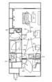
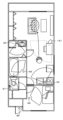
- FIG. It has a washroom, a bathroom, a toilet room, and an entrance.
- the behavior monitoring system 10 can be used, for example, to monitor the behavior of an elderly person or a person requiring care instead of a caregiver, and to quickly find an abnormality in the behavior.
- the monitoring device 30 includes a control section 31 , a communication section 32 , a display section 33 , a speaker 34 and sensors 40 .
- the control unit 31 is configured as a microprocessor centered around a CPU, and includes a ROM, a RAM, and the like in addition to the CPU.
- the display unit 33 and the speaker 34 output various information from the management server 20 by display and sound.
- the display unit 33 is configured as a touch panel type display unit that allows input by the operator.
- the sensors 40 are sensors for detecting where the person to be monitored who lives in the house is, and as shown in FIG. 46, 47 and a door sensor 48 provided at the front door.
- the human sensors 41 to 47 are sensors that detect a person within a detection area without contact, and are configured as infrared sensors that detect infrared rays and convert them into electrical signals, for example.
- Human sensors 41, 42, and 43 are provided in the living room, dining room, and kitchen of the LDK room, respectively.
- a human sensor 44 is provided in the bedroom, and a human sensor 45 is provided in the washroom.
- the human sensor 46 is provided in the bathroom, and the human sensor 47 is provided in the toilet room.
- the door sensor 48 detects opening and closing of the front door, and is configured as a magnet-type open/close sensor that has a permanent magnet fixed on the door side and a magnetic sensor fixed on the frame side, for example.
- the management server 20 includes a processing unit 21, a communication unit 22, and a storage unit 23.
- the processing unit 21 is configured as a microprocessor centered around a CPU, and includes a ROM, a RAM, and the like in addition to the CPU.
- the communication unit 22 of the management server 20 is connected to the communication unit 32 of each monitoring device 30 via the network 11 such as the Internet. exchange signals.
- the storage unit 23 is configured by an HDD, an SSD, or the like, receives data measured by each monitoring device 30, and stores the data for a certain period of time.
- the operation of each monitoring device 30 includes data measurement processing. Further, the operation of the management server 20 includes data reception processing and action determination processing.
- the data measurement process is the process of measuring (collecting) the whereabouts of the person being monitored from the sensors installed in each room of the residence.
- FIG. 3 is a flowchart showing an example of data measurement processing executed by the control unit 31 of each monitoring device 30. As shown in FIG. This process is repeatedly executed at predetermined time intervals.
- the control unit 31 of the monitoring device 30 first determines whether or not the human sensor 41 for the living room provided in the living room responds (step S100). When determining that the human sensor 41 for the living room responds, the control unit 31 determines that the monitored person is in the living room (step S102), and transmits the determination result to the management server 20 as measurement data. Then (step S136), the data measurement process ends.
- control unit 31 determines in step S100 that there is no response from the living sensor 41, it next determines whether there is a response from the dining sensor 42 provided in the dining room (step S100). S104). When the control unit 31 determines that the dining motion sensor 41 responds, it determines that the person to be monitored is in the dining room (step S106), and transmits the determination result to the management server 20 as measurement data. Then (step S136), the data measurement process ends.
- step S104 determines whether the human sensor 43 for the kitchen provided in the kitchen responds (step S104). S108).
- the control unit 31 determines that the human sensor 43 for the kitchen responds, it determines that the person to be monitored is in the kitchen (step S110), and transmits the determination result to the management server 20 as measurement data. Then (step S136), the data measurement process ends.
- step S108 determines whether the kitchen human sensor 43 provided in the bedroom responds. S112).
- step S114 determines that the person to be monitored is in the bedroom (step S114), and transmits the determination result to the management server 20 as measurement data. Then (step S136), the data measurement process ends.
- control unit 31 determines in step S112 that there is no response from the human sensor 44 for the bedroom, it next determines whether there is a response from the human sensor 45 for the washroom provided in the washroom (step S116). When determining that the human sensor 45 for the washroom responds, the control unit 31 determines that the person to be monitored is in the washroom (step S118), and sends the determination result to the management server 20 as measurement data. The data is transmitted (step S136), and the data measurement process ends.
- control unit 31 determines in step S116 that the human sensor 45 for the bathroom does not respond, it next determines whether the human sensor 46 for the bathroom provided in the bathroom responds (step S116). S120). When determining that the human sensor 46 for the bathroom responds, the control unit 31 determines that the monitored person is in the bathroom (step S122), and transmits the determination result to the management server 20 as measurement data. Then (step S136), the data measurement process ends.
- control unit 31 determines in step S120 that the human sensor 46 for the bathroom does not respond, it next determines whether the human sensor 47 for the toilet room provided in the toilet room responds. (Step S124). When determining that the human sensor 47 for the toilet room has responded, the control unit 31 determines that the person to be monitored is in the toilet room (step S126), and uses the determination result as measurement data to the management server 20. (step S136), and the data measurement process ends.
- step S124 determines whether the entrance door sensor 48 provided on the entrance door responds. S128).
- step S134 determines whether or not it is determined in step S134 described later that the person to be monitored is at home.
- step S132 determines that the person to be monitored has gone out (step S132), transmits the determination result to the management server 20 as measurement data (step S136), End the data measurement process.
- control unit 31 determines that the person to be monitored has not been determined to be at home (determined to be out of the house), it determines that the person to be monitored has returned home, that is, is at home (step S134). , the determination result is transmitted to the management server 20 as measurement data (step S136), and the data measurement process ends.
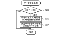
- the data reception process is a process of receiving measurement data transmitted from each monitoring device 30 .
- FIG. 4 is a flowchart showing an example of data reception processing executed by the processing unit 21 of the management server 20. As shown in FIG. This process is repeatedly executed at predetermined time intervals.
- the processing unit 21 of the management server 20 first determines whether measurement data has been received from the monitoring device 30 (step S200). When the processing unit 21 determines that the measurement data has not been received, it ends the data reception processing. On the other hand, when the processing unit 21 determines that it has received the measurement data, it accesses the time server via the Internet and acquires the current date, time (hour/minute/second) and day of the week as time information (step S202), the acquired time information is stored in the storage unit 23 in association with the received measurement data (step S204), and the data reception process ends.
- the time information may be obtained by reading the current time from an RTC (real time clock).
- FIG. 5 is a flowchart showing an example of action determination processing executed by the processing unit 21 of the management server 20. As shown in FIG. This process is repeatedly executed at predetermined time intervals.
- the processing unit 21 When the action determination process is executed, the processing unit 21 first stores measurement data (data of the room in which the person to be monitored was in) for a certain period of time (for example, one month or one week) in the storage unit 23. is accumulated (step S210). When the processing unit 21 determines that the measurement data for the fixed period has not been accumulated, the processing unit 21 ends the action determination processing. On the other hand, when the processing unit 21 determines that the measurement data for a certain period of time has been accumulated, the processing unit 21 sequentially extracts two points of measurement data that are continuous in time series from the measurement data for the certain period of time and have different room judgments ( Step S212), and the distance between two points is sequentially obtained based on the measurement data of the two points that are sequentially extracted (step S214).
- measurement data data of the room in which the person to be monitored was in
- a certain period of time for example, one month or one week
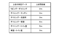
- the relationship between the measurement data of the two points and the distance between the two points is obtained in advance and registered in the storage unit 23 as a distance table between the two points. This is done by deriving the corresponding two-point distance from a two-point distance table.
- FIG. 6 shows an example of the distance table between two points.
- the processing unit 21 calculates the integrated value of the acquired distances between the two points for each unit time (for example, every 30 minutes or every hour), thereby calculating the unit time of the person to be monitored.
- the moving distance for each is calculated (step S216).
- the processing unit 21 aggregates the calculated movement distances for each unit time for each month, each week, and each day (step S218), and also counts the number of entry points for each room (by area) for each month, each week, and each day. The number of times is counted (step S220).
- the processing unit 21 compares the calculated moving distance with a value calculated in the past, and determines whether or not the moving distance of the monitored person has decreased by a predetermined amount or more (step S222). This determination may be made, for example, by comparing the value of the current day with the value of the previous day, the value of the current week with the value of the previous week, or the value of the current month with the value of the previous month. It may be done by comparing values. Alternatively, an evaluation value such as an average value of the aggregated values may be set, and the set evaluation value may be compared with past evaluation values.
- the processing unit 21 determines that the movement distance of the monitoring subject has not decreased by a predetermined amount or more, it determines that the walking function of the monitoring subject is normal (step S224), and outputs the determination result (normal) to the monitoring device 30. (step S232), and terminates the action determination process.
- the monitoring device 30 outputs from the display unit 33 or the speaker 34 that the current state is normal based on the received determination result.
- the processing unit 21 determines that the movement distance of the monitoring subject has decreased by a predetermined amount or more, it determines that the walking function of the monitoring subject has deteriorated (step S226). It is determined whether or not there is a room in which the number of times of entry has decreased by a predetermined amount or more by comparing with past values (step S228). This determination may be made for each room, for example, by comparing the current day's value with the previous day's value, the current week's value with the last week's value, or the current month's value. It may be done by comparing the value with the value of the previous month.
- the processing unit 21 determines that there is a corresponding room, it determines that there is an obstacle in the movement route toward the corresponding room (step S230), the walking function is deteriorated, and there is an obstacle in the movement route toward the corresponding room. is sent to the monitoring device 30 (step S232), and the action determination process is terminated.
- the processing unit 21 transmits the determination result that the walking function is degraded to the monitoring device 30 (step S232), and terminates the action determination process.
- the monitoring device 30 outputs to the display unit 33 and the speaker 34 the fact that the current state is abnormal and the content thereof based on the received determination result.
- the person to be monitored can recognize that the walking function is declining, which can be used for early treatment. Furthermore, by combining this with the presence or absence of a decrease in the number of times of entering the room, it is possible to confirm where the impact of the deterioration of walking function appears in daily life.
- the processing unit 21 transmits the movement distance per unit time, the number of times of room entry for each room, and the stay time for each room to the monitoring device 30, and the monitoring device 30 graphs these data. may be displayed on the display unit 33 (see FIG. 7).
- the processing unit 21 may transmit the determination result to a pre-registered information portable terminal such as a smart phone in order to notify the monitored person, the guardian of the monitored person, or the like.
- the human sensors 41 to 47 of the present embodiment correspond to the human sensors of the present disclosure
- the storage section 23 corresponds to the storage section
- the processing section 21 corresponds to the processing section
- the display unit 33 corresponds to the output unit.
- the human sensors 41 to 47 and the door sensor 48 correspond to detection means.
- the processing unit 21 estimates the room (area) where the person to be monitored is located based on the detection signals from the human sensors 41 to 47 provided in each room of the residence.
- a monitoring camera 141 is installed in some rooms (areas) in place of the human sensor, and the processing unit 21 detects the person to be monitored based on the imaging signal from the monitoring camera 141.
- the room (area) in which the user is present may be estimated.
- a destination room (area) may be estimated.
- the processing unit 21 detects that the person to be monitored is captured by the monitoring camera 141 whose imaging area is the dining room, and that the person to be monitored has moved toward the living room in the captured image. Once recognized, it can be inferred that the monitored person is in the living room.
- the processing unit 21 may use two human sensors whose detection areas are areas adjacent to each other to estimate the area where the person to be monitored exists even when the two human sensors do not react. .
- the processing unit 21 detects the presence of a person in the dining room.
- the sensitive sensor 42 changes from the unresponsive state to the responsive state to the unresponsive state, it can be estimated that the monitored person is in the living room. This makes it possible to reduce the number of human sensors.
- the processing unit 21 may detect the person to be monitored using a plurality of detection means pre-installed in the residence. For example, a person to be monitored may be detected based on signals from a plurality of lighting switches provided in each room for turning on and off the lighting in the room. In this case, the processing unit 21 registers the distance between rooms in advance, and when the lighting switch of one room is turned off from on among the rooms and then the lighting switch of the other room is turned on from off , the corresponding distance among the registered distances between rooms may be obtained as the moving distance.
- the processing unit acquires the distance between two points of the plurality of human sensors in advance and stores it in the storage unit. Then, when any of the plurality of motion sensors reacts, the reaction time is stored as reaction data in the storage unit, and based on the data stored in the storage unit, the moving distance of the person to be monitored per unit time is calculated. do. Since the motion sensor can detect the person to be monitored without contact, it can be installed at a position that does not interfere with the behavior of the person to be monitored. In addition, since the moving distance of the monitoring subject per unit time is calculated based on the reaction data (reaction time) of each human sensor, the behavior of the monitoring subject can be appropriately monitored with a simple configuration.
- the processing unit may further compare increases and decreases in the movement distance for each unit time in chronological order. By doing so, it is possible to accurately determine the deterioration of the monitoring subject's walking function with a simple configuration.
- an output unit may be provided that outputs a warning when the moving distance per unit time decreases by a predetermined distance or more in time series.
- the plurality of motion sensors are provided in each of the plurality of rooms of the residence, and the processing unit detects when any of the plurality of motion sensors reacts.
- the number of times a person to be monitored enters a room may be counted and stored in the storage unit. This makes it possible to appropriately grasp changes in the behavior of the person being monitored.
- the processing unit may further compare the increase/decrease in the number of times of room entry for each room in time series.
- an output unit may be provided that outputs a warning when the number of times of entering the room has decreased in time series by a predetermined number or more.
- the present disclosure is not limited to the form of a behavior monitoring system, and can also be in the form of a behavior monitoring method.
- the person to be monitored is detected using a plurality of detection means in the residence, and the distance between two points among the plurality of detection means is acquired in advance and stored in the storage unit.
- the reaction time is stored as reaction data in the storage unit, and the moving distance of the person to be monitored per unit time is calculated based on the data stored in the storage unit.
- the present disclosure can be used in the manufacturing industry of behavior monitoring systems.
Abstract
This behavior monitoring system comprises a detection unit, a storage unit, and a processing unit. The detection unit includes a plurality of human detection sensors that are installed in a residence, and that detect a monitored person in different detection regions in a non-contact manner. The processing unit acquires, in advance, the distance between two points associated with the plurality of human detection sensors, and stores the distance in the storage unit. Then, when one of the plurality of human detection sensors responds, the response time is stored in the storage unit as response data, and the distance traveled by the monitored person per unit time is calculated on the basis of the data stored in the storage unit.
Description
本明細書は、行動監視システムおよび行動監視方法について開示する。
This specification discloses a behavior monitoring system and a behavior monitoring method.
従来、この種の行動監視システムとしては、一人住まいの高齢者の健康状態を管理センタで遠隔診断するものが提案されている(例えば、特許文献1参照)。このシステムでは、住居に住む高齢者に関する複数の異なる生活データを測定して管理センタに送信する。複数の異なる生活データには、住宅の寝室、便所、玄関、居間、台所、浴室、洗面所などの出入口に設けた踏力マットのマット作動回数標準偏差、睡眠時間の情報値と補正値、マット作動頻度、移動速度、トイレ回数が含まれる。管理センタは、一日単位毎に各生活データを取り込み、単位期間における生活データ毎の平均値と標準偏差を求めると共に単位期間における複数の生活データ間の関連性を示す固有ベクトルを求めておく。管理センタは、一日単位の複数の生活データの測定値を入力すると、単位期間における生活データ毎の平均値と標準偏差を用いて各生活データの標準化データを算出し、各生活データの標準化データと各生活データ間の関連性を示す固有ベクトルのうち高齢者の生活リズムに影響が大きい2つの固有ベクトル成分とによって一日単位の生活パターン(行動パターン)を求める。そして、管理センタは、求めた生活パターンと過去の単位期間における生活パターンとの総合的な隔たりを監視して高齢者の健康状態を判定する。
Conventionally, as this type of behavior monitoring system, there has been proposed a system for remotely diagnosing the health condition of an elderly person living alone at a management center (see Patent Document 1, for example). The system measures and transmits to a control center a number of different life data relating to elderly people living in a residence. Multiple different life data include the standard deviation of the number of mat activations of the pedal force mat installed at the entrance of the bedroom, toilet, entrance, living room, kitchen, bathroom, washroom, etc., sleep time information value and correction value, mat activation Includes frequency, movement speed, and number of toilets. The management center acquires each piece of life data on a daily basis, obtains the average value and standard deviation for each piece of life data in a unit period, and obtains an eigenvector indicating the relationship between a plurality of pieces of life data in the unit period. When a plurality of measured values of daily life data are input, the management center calculates standardized data of each life data using the average value and standard deviation of each life data in the unit period, and standardized data of each life data. and two eigenvector components of the eigenvectors indicating the relationship between each piece of life data, which have a great influence on the life rhythm of the elderly. Then, the management center determines the health condition of the elderly person by monitoring the overall gap between the obtained life pattern and the life pattern in the past unit period.
しかしながら、上述したシステムでは、生活データの測定に踏力マットを用いるため、踏力マットを設置可能な場所が部屋の出入口に限られ、監視対象者の行動を監視するのに不十分な場合がある。また、歩行力が衰えた高齢者にとって、踏力マットが歩行の邪魔となるおそれもある。
However, in the system described above, since the force mat is used to measure life data, the place where the force mat can be installed is limited to the entrance/exit of the room, and it may not be sufficient to monitor the behavior of the monitored person. In addition, for elderly people whose walking ability has weakened, there is a risk that the pedal force mat will interfere with their walking.
本開示は、監視対象者の行動の邪魔になることなく、簡易な構成により監視対象者の行動を適切に監視可能とすることを主目的とする。
The main purpose of the present disclosure is to enable appropriate monitoring of the behavior of the monitoring target with a simple configuration without interfering with the behavior of the monitoring target.
本開示は、上述の主目的を達成するために以下の手段を採った。
This disclosure has taken the following means to achieve the above-mentioned main objectives.
本開示の行動監視システムは、住居に住む監視対象者の行動を監視する行動監視システムであって、前記住居に設置され、それぞれ異なる検知範囲内において監視対象者を非接触で検知する複数の人感センサを含む検知部と、データを記憶する記憶部と、予め前記複数の人感センサのうちの2点間距離を取得して前記記憶部に記憶しておき、前記複数の人感センサのいずれかに反応があった場合に反応時刻を反応データとして前記記憶部に記憶し、前記記憶部に記憶したデータに基づいて監視対象者の単位時間毎の移動距離を算出する処理部と、を備えることを要旨とする。
A behavior monitoring system of the present disclosure is a behavior monitoring system for monitoring the behavior of a person to be monitored who lives in a dwelling, and is installed in the dwelling and detects the person to be monitored without contact within different detection ranges. a detection unit including a sensor; a storage unit for storing data; a processing unit that stores the reaction time as reaction data in the storage unit when there is a reaction to any of them, and calculates the moving distance of the monitored person for each unit time based on the data stored in the storage unit; The gist of it is to be prepared.
この本開示の行動監視システムは、検知部と記憶部と処理部とを備える。検知部は、住居に設置され、それぞれ異なる検知範囲内において監視対象者を非接触で検知する複数の人感センサを含む。処理部は、予め複数の人感センサのうちの2点間距離を取得して記憶部に記憶しておく。そして、複数の人感センサのいずれかに反応があった場合に反応時刻を反応データとして記憶部に記憶し、記憶部に記憶したデータに基づいて監視対象者の単位時間毎の移動距離を算出する。検知部は監視対象者を非接触で検知可能な人感センサで構成されるため、設置の自由度があり、監視対象者の行動の邪魔にならない位置に設置可能である。また、各人感センサの反応データ(反応時刻)に基づいて監視対象者の単位時間毎の移動距離を算出するため、簡易な構成により監視対象者の行動を適切に監視することができる。
The behavior monitoring system of this disclosure includes a detection unit, a storage unit, and a processing unit. The detection unit is installed in a residence and includes a plurality of motion sensors that detect the person to be monitored in a different detection range without contact. The processing unit acquires in advance the distance between two points of the plurality of human sensors and stores it in the storage unit. Then, when any of the plurality of motion sensors reacts, the reaction time is stored as reaction data in the storage unit, and based on the data stored in the storage unit, the moving distance of the person to be monitored per unit time is calculated. do. Since the detection unit is composed of a motion sensor that can detect the person to be monitored without contact, there is a degree of freedom in installation, and it can be installed in a position that does not interfere with the behavior of the person to be monitored. In addition, since the moving distance of the monitoring subject per unit time is calculated based on the reaction data (reaction time) of each human sensor, the behavior of the monitoring subject can be appropriately monitored with a simple configuration.
本開示の行動監視方法は、住居に住む監視対象者の行動を監視する行動監視方法であって、前記住居において、複数の検知手段を用いて監視対象者を検知するものであり、予め前記複数の検知手段のうちの2点間距離を取得して記憶部に記憶しておき、前記複数の検知手段のいずれかに反応があった場合に反応時刻を反応データとして前記記憶部に記憶し、前記記憶部に記憶したデータに基づいて監視対象者の単位時間毎の移動距離を算出することを要旨とする。
A behavior monitoring method of the present disclosure is a behavior monitoring method for monitoring the behavior of a person to be monitored living in a dwelling, wherein the person to be monitored is detected using a plurality of detection means in the dwelling. acquires the distance between two points of the detection means and stores it in a storage unit, and when there is a reaction in any of the plurality of detection means, stores the reaction time in the storage unit as reaction data, The gist of the invention is to calculate a movement distance of a person to be monitored per unit time based on data stored in the storage unit.
この本開示の行動監視方法は、複数の検知手段の反応データ(反応時刻)に基づいて監視対象者の単位時間毎の移動距離を算出するため、簡易な構成により監視対象者の行動を適切に監視することができる。また、検知手段として、例えば照明スイッチ等の住居に備え付けられている検知手段を用いることで、新たにセンサを設置することなく監視対象者の行動を監視することができる。
Since the behavior monitoring method of the present disclosure calculates the movement distance of the monitoring subject per unit time based on the reaction data (reaction time) of a plurality of detection means, the behavior of the monitoring subject can be appropriately monitored with a simple configuration. can be monitored. In addition, by using a detection means such as a lighting switch installed in a residence as the detection means, the behavior of the person to be monitored can be monitored without installing a new sensor.
次に、本開示を実施するための形態について図面を参照しながら説明する。
Next, a mode for carrying out the present disclosure will be described with reference to the drawings.
図1は、本実施形態の行動監視システム10の概略構成図である。本実施形態の行動監視システム10は、図1に示すように、システム全体を管理する管理サーバ20と、監視対象者が住む各住居A~Cにそれぞれ設置された監視装置30と、を備える。なお、住居A~Cは、例えば高齢者や要介護者が一人暮らしをするための住居であり、例えば、図2に示すように、L(リビング)D(ダイニング)K(キッチン)室と寝室と洗面所と浴室とトイレ室と玄関とを有する。行動監視システム10は、例えば、介護者に代わって、高齢者や要介護者を監視対象者としてその行動を監視し、行動の異常を早期に見つけ出すために用いることができる。
FIG. 1 is a schematic configuration diagram of the behavior monitoring system 10 of this embodiment. As shown in FIG. 1, the behavior monitoring system 10 of this embodiment includes a management server 20 that manages the entire system, and monitoring devices 30 that are installed in residences A to C where persons to be monitored live. In addition, the residences A to C are, for example, residences for the elderly or people requiring nursing care to live alone. For example, as shown in FIG. It has a washroom, a bathroom, a toilet room, and an entrance. The behavior monitoring system 10 can be used, for example, to monitor the behavior of an elderly person or a person requiring care instead of a caregiver, and to quickly find an abnormality in the behavior.
監視装置30は、制御部31と通信部32と表示部33とスピーカ34とセンサ類40とを備える。制御部31は、CPUを中心としたマイクロプロセッサとして構成され、CPUの他にROMやRAM等を備える。表示部33およびスピーカ34は、管理サーバ20からの各種情報を表示や音声によって出力するものである。本実施形態では、表示部33は、操作者による入力が可能なタッチパネル式の表示部として構成される。
The monitoring device 30 includes a control section 31 , a communication section 32 , a display section 33 , a speaker 34 and sensors 40 . The control unit 31 is configured as a microprocessor centered around a CPU, and includes a ROM, a RAM, and the like in addition to the CPU. The display unit 33 and the speaker 34 output various information from the management server 20 by display and sound. In this embodiment, the display unit 33 is configured as a touch panel type display unit that allows input by the operator.
センサ類40は、住居に住む監視対象者がどこにいるのかを検知するためのセンサであり、図2に示すように、各部屋に設けられた人感センサ41,42,43,44,45,46,47と、玄関ドアに設けられたドアセンサ48とを含む。
The sensors 40 are sensors for detecting where the person to be monitored who lives in the house is, and as shown in FIG. 46, 47 and a door sensor 48 provided at the front door.
人感センサ41~47は、非接触により検知エリア内の人を検知するセンサであり、例えば、赤外線を感知して電気信号に変換する赤外線センサとして構成される。人感センサ41,42,43は、それぞれLDK室のリビング,ダイニング,キッチンに設けられている。人感センサ44は、寝室に設けられ、人感センサ45は、洗面所に設けられている。また、人感センサ46は、浴室に設けられ、人感センサ47は、トイレ室に設けられている。
The human sensors 41 to 47 are sensors that detect a person within a detection area without contact, and are configured as infrared sensors that detect infrared rays and convert them into electrical signals, for example. Human sensors 41, 42, and 43 are provided in the living room, dining room, and kitchen of the LDK room, respectively. A human sensor 44 is provided in the bedroom, and a human sensor 45 is provided in the washroom. Also, the human sensor 46 is provided in the bathroom, and the human sensor 47 is provided in the toilet room.
ドアセンサ48は、玄関ドアの開閉を検知するものであり、例えば、ドア側に固定された永久磁石と枠側に固定された磁気センサとを有する磁石式の開閉センサとして構成される。
The door sensor 48 detects opening and closing of the front door, and is configured as a magnet-type open/close sensor that has a permanent magnet fixed on the door side and a magnetic sensor fixed on the frame side, for example.
管理サーバ20は、処理部21と通信部22と記憶部23とを備える。処理部21は、CPUを中心としたマイクロプロセッサとして構成され、CPUの他にROMやRAM等を備える。管理サーバ20の通信部22は、インターネット等のネットワーク11を介して各監視装置30の通信部32と接続され、管理サーバ20と各監視装置30は、通信部22,32を介して互いにデータや信号をやり取りする。記憶部23は、HDDやSSD等により構成され、各監視装置30で測定されたデータを受信して一定期間に亘って記憶する。
The management server 20 includes a processing unit 21, a communication unit 22, and a storage unit 23. The processing unit 21 is configured as a microprocessor centered around a CPU, and includes a ROM, a RAM, and the like in addition to the CPU. The communication unit 22 of the management server 20 is connected to the communication unit 32 of each monitoring device 30 via the network 11 such as the Internet. exchange signals. The storage unit 23 is configured by an HDD, an SSD, or the like, receives data measured by each monitoring device 30, and stores the data for a certain period of time.
次に、こうして構成された行動監視システムの動作、すなわち、各監視装置30の動作と管理サーバ20の動作とについて説明する。各監視装置30の動作には、データ測定処理が含まれる。また、管理サーバ20の動作には、データ受信処理と行動判定処理とが含まれる。
Next, the operation of the behavior monitoring system configured in this way, that is, the operation of each monitoring device 30 and the operation of the management server 20 will be described. The operation of each monitoring device 30 includes data measurement processing. Further, the operation of the management server 20 includes data reception processing and action determination processing.
データ測定処理は、住居の各部屋に設けられたセンサから監視対象者の居場所を測定(収集)する処理である。図3は、各監視装置30の制御部31により実行されるデータ測定処理の一例を示すフローチャートである。この処理は、所定時間毎に繰り返し実行される。
The data measurement process is the process of measuring (collecting) the whereabouts of the person being monitored from the sensors installed in each room of the residence. FIG. 3 is a flowchart showing an example of data measurement processing executed by the control unit 31 of each monitoring device 30. As shown in FIG. This process is repeatedly executed at predetermined time intervals.
データ測定処理が実行されると、監視装置30の制御部31は、まず、リビングに設けられたリビング用の人感センサ41に反応があるか否かを判定する(ステップS100)。制御部31は、リビング用の人感センサ41に反応があると判定すると、監視対象者はリビングに在室していると判定し(ステップS102)、判定結果を測定データとして管理サーバ20に送信して(ステップS136)、データ測定処理を終了する。
When the data measurement process is executed, the control unit 31 of the monitoring device 30 first determines whether or not the human sensor 41 for the living room provided in the living room responds (step S100). When determining that the human sensor 41 for the living room responds, the control unit 31 determines that the monitored person is in the living room (step S102), and transmits the determination result to the management server 20 as measurement data. Then (step S136), the data measurement process ends.
制御部31は、ステップS100でリビング用の人感センサ41に反応がないと判定すると、次に、ダイニングに設けられたダイニング用の人感センサ42に反応があるか否かを判定する(ステップS104)。制御部31は、ダイニング用の人感センサ41に反応があると判定すると、監視対象者はダイニングに在室していると判定し(ステップS106)、判定結果を測定データとして管理サーバ20に送信して(ステップS136)、データ測定処理を終了する。
When the control unit 31 determines in step S100 that there is no response from the living sensor 41, it next determines whether there is a response from the dining sensor 42 provided in the dining room (step S100). S104). When the control unit 31 determines that the dining motion sensor 41 responds, it determines that the person to be monitored is in the dining room (step S106), and transmits the determination result to the management server 20 as measurement data. Then (step S136), the data measurement process ends.
制御部31は、ステップS104でダイニング用の人感センサ42に反応がないと判定すると、次に、キッチンに設けられたキッチン用の人感センサ43に反応があるか否かを判定する(ステップS108)。制御部31は、キッチン用の人感センサ43に反応があると判定すると、監視対象者はキッチンに在室していると判定し(ステップS110)、判定結果を測定データとして管理サーバ20に送信して(ステップS136)、データ測定処理を終了する。
When the controller 31 determines in step S104 that the human sensor 42 for dining does not respond, it next determines whether the human sensor 43 for the kitchen provided in the kitchen responds (step S104). S108). When the control unit 31 determines that the human sensor 43 for the kitchen responds, it determines that the person to be monitored is in the kitchen (step S110), and transmits the determination result to the management server 20 as measurement data. Then (step S136), the data measurement process ends.
制御部31は、ステップS108でキッチン用の人感センサ43に反応がないと判定すると、次に、寝室に設けられた寝室用の人感センサ44に反応があるか否かを判定する(ステップS112)。制御部31は、寝室用の人感センサ44に反応があると判定すると、監視対象者は寝室に在室していると判定し(ステップS114)、判定結果を測定データとして管理サーバ20に送信して(ステップS136)、データ測定処理を終了する。
When the controller 31 determines in step S108 that the kitchen human sensor 43 does not respond, it next determines whether the bedroom human sensor 44 provided in the bedroom responds (step S108). S112). When determining that the motion sensor 44 for the bedroom responds, the control unit 31 determines that the person to be monitored is in the bedroom (step S114), and transmits the determination result to the management server 20 as measurement data. Then (step S136), the data measurement process ends.
制御部31は、ステップS112で寝室用の人感センサ44に反応がないと判定すると、次に、洗面所に設けられた洗面所用の人感センサ45に反応があるか否かを判定する(ステップS116)。制御部31は、洗面所用の人感センサ45に反応があると判定すると、監視対象者は洗面所に在室していると判定し(ステップS118)、判定結果を測定データとして管理サーバ20に送信して(ステップS136)、データ測定処理を終了する。
If the control unit 31 determines in step S112 that there is no response from the human sensor 44 for the bedroom, it next determines whether there is a response from the human sensor 45 for the washroom provided in the washroom ( step S116). When determining that the human sensor 45 for the washroom responds, the control unit 31 determines that the person to be monitored is in the washroom (step S118), and sends the determination result to the management server 20 as measurement data. The data is transmitted (step S136), and the data measurement process ends.
制御部31は、ステップS116で洗面所用の人感センサ45に反応がないと判定すると、次に、浴室に設けられた浴室用の人感センサ46に反応があるか否かを判定する(ステップS120)。制御部31は、浴室用の人感センサ46に反応があると判定すると、監視対象者は浴室に在室していると判定し(ステップS122)、判定結果を測定データとして管理サーバ20に送信して(ステップS136)、データ測定処理を終了する。
If the control unit 31 determines in step S116 that the human sensor 45 for the bathroom does not respond, it next determines whether the human sensor 46 for the bathroom provided in the bathroom responds (step S116). S120). When determining that the human sensor 46 for the bathroom responds, the control unit 31 determines that the monitored person is in the bathroom (step S122), and transmits the determination result to the management server 20 as measurement data. Then (step S136), the data measurement process ends.
制御部31は、ステップS120で浴室用の人感センサ46に反応がないと判定すると、次に、トイレ室に設けられたトイレ室用の人感センサ47に反応があるか否かを判定する(ステップS124)。制御部31は、トイレ室用の人感センサ47に反応があると判定すると、監視対象者はトイレ室に在室していると判定し(ステップS126)、判定結果を測定データとして管理サーバ20に送信して(ステップS136)、データ測定処理を終了する。
If the control unit 31 determines in step S120 that the human sensor 46 for the bathroom does not respond, it next determines whether the human sensor 47 for the toilet room provided in the toilet room responds. (Step S124). When determining that the human sensor 47 for the toilet room has responded, the control unit 31 determines that the person to be monitored is in the toilet room (step S126), and uses the determination result as measurement data to the management server 20. (step S136), and the data measurement process ends.
制御部31は、ステップS124でトイレ室用の人感センサ47に反応がないと判定すると、次に、玄関ドアに設けられた玄関用のドアセンサ48に反応があるか否かを判定する(ステップS128)。制御部31は、玄関用のドアセンサ48に反応があると判定すると、後述するステップS134により監視対象者は在宅中であると判定されているか否かを判定する(ステップS130)。制御部31は、在宅中であると判定されていると判定すると、監視対象者は外出したと判定し(ステップS132)、判定結果を測定データとして管理サーバ20に送信して(ステップS136)、データ測定処理を終了する。一方、制御部31は、在宅中であると判定されていない(外出中であると判定されている)と判定すると、監視対象者は帰宅した、すなわち在宅中であると判定し(ステップS134)、判定結果を測定データとして管理サーバ20に送信して(ステップS136)、データ測定処理を終了する。
When the controller 31 determines in step S124 that the toilet room human sensor 47 does not respond, it next determines whether the entrance door sensor 48 provided on the entrance door responds (step S124). S128). When determining that the entrance door sensor 48 has responded, the control unit 31 determines whether or not it is determined in step S134 described later that the person to be monitored is at home (step S130). When it is determined that the person to be monitored is at home, the control unit 31 determines that the person to be monitored has gone out (step S132), transmits the determination result to the management server 20 as measurement data (step S136), End the data measurement process. On the other hand, when the control unit 31 determines that the person to be monitored has not been determined to be at home (determined to be out of the house), it determines that the person to be monitored has returned home, that is, is at home (step S134). , the determination result is transmitted to the management server 20 as measurement data (step S136), and the data measurement process ends.
次に、管理サーバ20の動作(データ受信処理および行動判定処理)について説明する。
Next, the operation of the management server 20 (data reception processing and action determination processing) will be described.
データ受信処理は、各監視装置30から送信された測定データを受信する処理である。図4は、管理サーバ20の処理部21により実行されるデータ受信処理の一例を示すフローチャートである。この処理は、所定時間毎に繰り返し実行される。
The data reception process is a process of receiving measurement data transmitted from each monitoring device 30 . FIG. 4 is a flowchart showing an example of data reception processing executed by the processing unit 21 of the management server 20. As shown in FIG. This process is repeatedly executed at predetermined time intervals.
データ受信処理が実行されると、管理サーバ20の処理部21は、まず、監視装置30から測定データを受信したか否かを判定する(ステップS200)。処理部21は、測定データを受信していないと判定すると、データ受信処理を終了する。一方、処理部21は、測定データを受信したと判定すると、インターネットを介して時刻サーバにアクセスして現在の年月日、時間(時/分/秒)および曜日を時刻情報として取得し(ステップS202)、取得した時刻情報を受信した測定データと関連付けて記憶部23に記憶して(ステップS204)、データ受信処理を終了する。なお、時刻情報の取得は、RTC(リアルタイムクロック)から現在の時刻を読み取ることにより行なわれてもよい。
When the data reception process is executed, the processing unit 21 of the management server 20 first determines whether measurement data has been received from the monitoring device 30 (step S200). When the processing unit 21 determines that the measurement data has not been received, it ends the data reception processing. On the other hand, when the processing unit 21 determines that it has received the measurement data, it accesses the time server via the Internet and acquires the current date, time (hour/minute/second) and day of the week as time information (step S202), the acquired time information is stored in the storage unit 23 in association with the received measurement data (step S204), and the data reception process ends. The time information may be obtained by reading the current time from an RTC (real time clock).
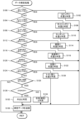
行動判定処理は、各監視装置30から収集した測定データに基づいて監視対象者の行動の適否を判定するものである。図5は、管理サーバ20の処理部21により実行される行動判定処理の一例を示すフローチャートである。この処理は、所定時間毎に繰り返し実行される。
The behavior determination process determines whether the behavior of the person being monitored is appropriate based on the measurement data collected from each monitoring device 30 . FIG. 5 is a flowchart showing an example of action determination processing executed by the processing unit 21 of the management server 20. As shown in FIG. This process is repeatedly executed at predetermined time intervals.
行動判定処理が実行されると、処理部21は、まず、記憶部23に一定期間分(例えば1ヶ月分や1週間分)の測定データ(監視対象者が在室していた部屋のデータ)が蓄積されているか否かを判定する(ステップS210)。処理部21は、一定期間分の測定データが蓄積されていないと判定すると、行動判定処理を終了する。一方、処理部21は、一定期間分の測定データが蓄積されていると判定すると、一定期間分の測定データから時系列で連続すると共に部屋の判定が異なる2点の測定データを順次抽出し(ステップS212)、順次抽出した2点の測定データに基づいて2点間距離を順次取得する(ステップS214)。2点間距離の取得は、2点の測定データと2点間距離との関係を予め求めて2点間距離テーブルとして記憶部23に登録しておき、2点の測定データが与えられると、2点間距離テーブルから対応する2点間距離を導出することにより行なわれる。図6に、2点間距離テーブルの一例を示す。
When the action determination process is executed, the processing unit 21 first stores measurement data (data of the room in which the person to be monitored was in) for a certain period of time (for example, one month or one week) in the storage unit 23. is accumulated (step S210). When the processing unit 21 determines that the measurement data for the fixed period has not been accumulated, the processing unit 21 ends the action determination processing. On the other hand, when the processing unit 21 determines that the measurement data for a certain period of time has been accumulated, the processing unit 21 sequentially extracts two points of measurement data that are continuous in time series from the measurement data for the certain period of time and have different room judgments ( Step S212), and the distance between two points is sequentially obtained based on the measurement data of the two points that are sequentially extracted (step S214). To acquire the distance between two points, the relationship between the measurement data of the two points and the distance between the two points is obtained in advance and registered in the storage unit 23 as a distance table between the two points. This is done by deriving the corresponding two-point distance from a two-point distance table. FIG. 6 shows an example of the distance table between two points.
処理部21は、各2点間距離を順次取得すると、取得した各2点間距離の単位時間毎(例えば30分間毎や1時間毎)の積算値を算出することにより監視対象者の単位時間毎の移動距離を算出する(ステップS216)。続いて、処理部21は、算出した単位時間毎の移動距離を月毎、週毎および日毎にそれぞれ集計すると共に(ステップS218)、月毎、週毎および日毎に部屋別(エリア別)の入室回数を集計する(ステップS220)。次に、処理部21は、算出した移動距離と過去に算出した値とを比較して監視対象者の移動距離が所定程度以上減少したか否かを判定する(ステップS222)。この判定は、例えば、当日の値と前日の値とを比較することにより行なってもよいし、今週の値と先週の値とを比較することにより行なってもよいし、今月の値と先月の値とを比較することにより行なってもよい。また、集計した値の平均値などの評価値を設定し、設定した評価値を過去の評価値とを比較することにより行なってもよい。処理部21は、監視対象者の移動距離が所定程度以上減少していないと判定すると、監視対象者の歩行機能は正常であると判定し(ステップS224)、判定結果(正常)を監視装置30に送信して(ステップS232)、行動判定処理を終了する。監視装置30は、受信した判定結果に基づいて現在の状態は正常である旨を表示部33やスピーカ34から出力する。
After sequentially acquiring the distances between the two points, the processing unit 21 calculates the integrated value of the acquired distances between the two points for each unit time (for example, every 30 minutes or every hour), thereby calculating the unit time of the person to be monitored. The moving distance for each is calculated (step S216). Subsequently, the processing unit 21 aggregates the calculated movement distances for each unit time for each month, each week, and each day (step S218), and also counts the number of entry points for each room (by area) for each month, each week, and each day. The number of times is counted (step S220). Next, the processing unit 21 compares the calculated moving distance with a value calculated in the past, and determines whether or not the moving distance of the monitored person has decreased by a predetermined amount or more (step S222). This determination may be made, for example, by comparing the value of the current day with the value of the previous day, the value of the current week with the value of the previous week, or the value of the current month with the value of the previous month. It may be done by comparing values. Alternatively, an evaluation value such as an average value of the aggregated values may be set, and the set evaluation value may be compared with past evaluation values. If the processing unit 21 determines that the movement distance of the monitoring subject has not decreased by a predetermined amount or more, it determines that the walking function of the monitoring subject is normal (step S224), and outputs the determination result (normal) to the monitoring device 30. (step S232), and terminates the action determination process. The monitoring device 30 outputs from the display unit 33 or the speaker 34 that the current state is normal based on the received determination result.
一方、処理部21は、監視対象者の移動距離が所定程度以上減少したと判定すると、監視対象者の歩行機能が低下していると判定し(ステップS226)、更に部屋別に集計した入室回数と過去の値とを比較して入室回数が所定程度以上減少した部屋があるか否かを判定する(ステップS228)。この判定は、部屋毎に、例えば、当日の値と前日の値とを比較することにより行なってもよいし、今週の値と先週の値とを比較することにより行なってもよいし、今月の値と先月の値とを比較することにより行なってもよい。処理部21は、該当する部屋があると判定すると、該当する部屋に向かう移動ルートに障害があると判定し(ステップS230)、歩行機能が低下し、該当する部屋に向かう移動ルートに障害があるとの判定結果を監視装置30に送信して(ステップS232)、行動判定処理を終了する。一方、処理部21は、ステップS228で該当する部屋がないと判定すると、歩行機能が低下しているとの判定結果を監視装置30に送信して(ステップS232)、行動判定処理を終了する。監視装置30は、受信した判定結果に基づいて現在の状態は異常である旨やその内容を表示部33やスピーカ34に出力する。これにより、監視対象者は歩行機能が低下していること把握することができ、早期治療に役立てることができる。更に、入室回数の減少の有無と組み合わせることで、歩行機能の低下による影響が生活のどこに現われているのかを確認することができる。
On the other hand, when the processing unit 21 determines that the movement distance of the monitoring subject has decreased by a predetermined amount or more, it determines that the walking function of the monitoring subject has deteriorated (step S226). It is determined whether or not there is a room in which the number of times of entry has decreased by a predetermined amount or more by comparing with past values (step S228). This determination may be made for each room, for example, by comparing the current day's value with the previous day's value, the current week's value with the last week's value, or the current month's value. It may be done by comparing the value with the value of the previous month. When the processing unit 21 determines that there is a corresponding room, it determines that there is an obstacle in the movement route toward the corresponding room (step S230), the walking function is deteriorated, and there is an obstacle in the movement route toward the corresponding room. is sent to the monitoring device 30 (step S232), and the action determination process is terminated. On the other hand, when determining that there is no corresponding room in step S228, the processing unit 21 transmits the determination result that the walking function is degraded to the monitoring device 30 (step S232), and terminates the action determination process. The monitoring device 30 outputs to the display unit 33 and the speaker 34 the fact that the current state is abnormal and the content thereof based on the received determination result. As a result, the person to be monitored can recognize that the walking function is declining, which can be used for early treatment. Furthermore, by combining this with the presence or absence of a decrease in the number of times of entering the room, it is possible to confirm where the impact of the deterioration of walking function appears in daily life.
なお、処理部21は、単位時間毎の移動距離や、部屋別の入室回数、部屋別の滞在時間を監視装置30に送信することで、当該監視装置30が、これらのデータをグラフ化したものを表示部33に表示するようにしてもよい(図7参照)。また、処理部21は、判定結果を監視対象者や当該監視対象者の保護者等に通知するために、予め登録されているスマートフォン等の情報携帯端末に送信するようにしてもよい。
Note that the processing unit 21 transmits the movement distance per unit time, the number of times of room entry for each room, and the stay time for each room to the monitoring device 30, and the monitoring device 30 graphs these data. may be displayed on the display unit 33 (see FIG. 7). In addition, the processing unit 21 may transmit the determination result to a pre-registered information portable terminal such as a smart phone in order to notify the monitored person, the guardian of the monitored person, or the like.
ここで、実施形態の主要な要素と請求の範囲に記載した本開示の主要な要素との対応関係について説明する。即ち、本実施形態の人感センサ41~47が本開示の人感センサに相当し、記憶部23が記憶部に相当し、処理部21が処理部に相当する。また、表示部33が出力部に相当する。人感センサ41~47やドアセンサ48が検知手段に相当する。
Here, the correspondence between the main elements of the embodiment and the main elements of the present disclosure described in the claims will be described. That is, the human sensors 41 to 47 of the present embodiment correspond to the human sensors of the present disclosure, the storage section 23 corresponds to the storage section, and the processing section 21 corresponds to the processing section. Also, the display unit 33 corresponds to the output unit. The human sensors 41 to 47 and the door sensor 48 correspond to detection means.
なお、本開示は上述した実施形態に何ら限定されることはなく、本開示の技術的範囲に属する限り種々の態様で実施し得ることはいうまでもない。
It goes without saying that the present disclosure is by no means limited to the above-described embodiments, and can be implemented in various forms as long as they fall within the technical scope of the present disclosure.
例えば、上述した実施形態では、処理部21は、住居の各部屋に設けられた人感センサ41~47からの検知信号に基づいて監視対象者のいる部屋(エリア)を推定するものとした。しかし、図8に示すように、一部の部屋(エリア)については人感センサに代えて監視カメラ141が設置され、処理部21は、監視カメラ141からの撮像信号に基づいて監視対象者のいる部屋(エリア)を推定するものとしてもよい。この場合、監視対象者が監視カメラ141の撮像エリア内から撮像エリア外へと移動したときには、当該撮像エリア内において監視対象者が移動した方向を撮像画像から認識することにより、当該監視対象者の移動先の部屋(エリア)を推定するようにしてもよい。例えば、処理部21は、図8および図9に示すように、ダイニングを撮像エリアとする監視カメラ141で監視対象者が撮像され、撮像画像において監視対象者がリビングへ向かう方向へ移動したことが認識されると、当該監視対象者はリビングにいると推定することができる。
For example, in the above-described embodiment, the processing unit 21 estimates the room (area) where the person to be monitored is located based on the detection signals from the human sensors 41 to 47 provided in each room of the residence. However, as shown in FIG. 8, a monitoring camera 141 is installed in some rooms (areas) in place of the human sensor, and the processing unit 21 detects the person to be monitored based on the imaging signal from the monitoring camera 141. The room (area) in which the user is present may be estimated. In this case, when the person to be monitored moves from within the imaging area of the monitoring camera 141 to outside the imaging area, the direction in which the person to be monitored moves within the imaging area is recognized from the captured image, thereby allowing the person to be monitored to move. A destination room (area) may be estimated. For example, as shown in FIGS. 8 and 9, the processing unit 21 detects that the person to be monitored is captured by the monitoring camera 141 whose imaging area is the dining room, and that the person to be monitored has moved toward the living room in the captured image. Once recognized, it can be inferred that the monitored person is in the living room.
また、処理部21は、互いに隣接するエリアを検知エリアとする2つの人感センサを用いて当該2つの人感センサが反応しない場合においても監視対象者のいるエリアを推定するようにしてもよい。例えば、処理部21は、図10に示すように、LDK室において、キッチンに設けられた人感センサ43が無反応状態から反応状態、無反応状態へと変化した後、ダイニングに設けられた人感センサ42が無反応状態から反応状態、無反応状態へと変化した場合には、監視対象者はリビングにいると推定することができる。これにより、人感センサの数を削減することが可能である。
In addition, the processing unit 21 may use two human sensors whose detection areas are areas adjacent to each other to estimate the area where the person to be monitored exists even when the two human sensors do not react. . For example, as shown in FIG. 10, in the LDK room, after the human sensor 43 provided in the kitchen changes from the unresponsive state to the responsive state and then to the unresponsive state, the processing unit 21 detects the presence of a person in the dining room. When the sensitive sensor 42 changes from the unresponsive state to the responsive state to the unresponsive state, it can be estimated that the monitored person is in the living room. This makes it possible to reduce the number of human sensors.
さらに、処理部21は、住居に予め備え付けられている複数の検知手段を用いて監視対象者を検知するようにしてもよい。例えば、部屋の照明を点灯および消灯させるために部屋毎に設けられた複数の照明スイッチからの信号に基づいて監視対象者を検知してもよい。この場合、処理部21は、予め部屋間の距離を登録しておき、部屋間で一方の部屋の照明スイッチがオンからオフされ、その後、他方の部屋の照明スイッチがオフからオンされたときに、登録した部屋間の距離のうち対応する距離を移動距離として取得してもよい。
Furthermore, the processing unit 21 may detect the person to be monitored using a plurality of detection means pre-installed in the residence. For example, a person to be monitored may be detected based on signals from a plurality of lighting switches provided in each room for turning on and off the lighting in the room. In this case, the processing unit 21 registers the distance between rooms in advance, and when the lighting switch of one room is turned off from on among the rooms and then the lighting switch of the other room is turned on from off , the corresponding distance among the registered distances between rooms may be obtained as the moving distance.
以上説明した本開示の行動監視システムでは、処理部は、予め複数の人感センサのうちの2点間距離を取得して記憶部に記憶しておく。そして、複数の人感センサのいずれかに反応があった場合に反応時刻を反応データとして記憶部に記憶し、記憶部に記憶したデータに基づいて監視対象者の単位時間毎の移動距離を算出する。人感センサは監視対象者を非接触で検知可能であるため、設置の自由度があり、監視対象者の行動の邪魔にならない位置に設置可能である。また、各人感センサの反応データ(反応時刻)に基づいて監視対象者の単位時間毎の移動距離を算出するため、簡易な構成により監視対象者の行動を適切に監視することができる。
In the behavior monitoring system of the present disclosure described above, the processing unit acquires the distance between two points of the plurality of human sensors in advance and stores it in the storage unit. Then, when any of the plurality of motion sensors reacts, the reaction time is stored as reaction data in the storage unit, and based on the data stored in the storage unit, the moving distance of the person to be monitored per unit time is calculated. do. Since the motion sensor can detect the person to be monitored without contact, it can be installed at a position that does not interfere with the behavior of the person to be monitored. In addition, since the moving distance of the monitoring subject per unit time is calculated based on the reaction data (reaction time) of each human sensor, the behavior of the monitoring subject can be appropriately monitored with a simple configuration.
こうした本開示の行動監視システムにおいて、前記処理部は、更に前記単位時間毎の移動距離の増減を時系列で比較してもよい。こうすれば、簡易な構成により監視対象者の歩行機能の低下を精度良く判定することができる。この場合、前記単位時間毎の移動距離が所定距離以上、時系列で減少した場合に警告を出力する出力部を備えてもよい。
In the behavior monitoring system of the present disclosure, the processing unit may further compare increases and decreases in the movement distance for each unit time in chronological order. By doing so, it is possible to accurately determine the deterioration of the monitoring subject's walking function with a simple configuration. In this case, an output unit may be provided that outputs a warning when the moving distance per unit time decreases by a predetermined distance or more in time series.
また、本開示の行動監視システムにおいて、前記複数の人感センサは、前記住居の複数の部屋にそれぞれ設けられ、前記処理部は、前記複数の人感センサのいずれかに反応があった場合に部屋毎に監視対象者の入室回数を計数して前記記憶部に記憶してもよい。こうすれば、監視対象者の行動の変化を適切に把握することが可能となる。この場合、前記処理部は、更に前記部屋毎の入室回数の増減を時系列で比較してもよい。さらにこの場合、前記部屋の入室回数が所定回数以上、時系列で減少した場合に警告を出力する出力部を備えてもよい。
Further, in the behavior monitoring system of the present disclosure, the plurality of motion sensors are provided in each of the plurality of rooms of the residence, and the processing unit detects when any of the plurality of motion sensors reacts. The number of times a person to be monitored enters a room may be counted and stored in the storage unit. This makes it possible to appropriately grasp changes in the behavior of the person being monitored. In this case, the processing unit may further compare the increase/decrease in the number of times of room entry for each room in time series. Furthermore, in this case, an output unit may be provided that outputs a warning when the number of times of entering the room has decreased in time series by a predetermined number or more.
また、本開示は、行動監視システムの形態とするものに限られず、行動監視方法の形態とすることもできる。この場合、前記住居において、複数の検知手段を用いて監視対象者を検知するものであり、予め前記複数の検知手段のうちの2点間距離を取得して記憶部に記憶しておき、前記複数の検知手段のいずれかに反応があった場合に反応時刻を反応データとして前記記憶部に記憶し、前記記憶部に記憶したデータに基づいて監視対象者の単位時間毎の移動距離を算出してもよい。
In addition, the present disclosure is not limited to the form of a behavior monitoring system, and can also be in the form of a behavior monitoring method. In this case, the person to be monitored is detected using a plurality of detection means in the residence, and the distance between two points among the plurality of detection means is acquired in advance and stored in the storage unit. When there is a reaction in any of the plurality of detection means, the reaction time is stored as reaction data in the storage unit, and the moving distance of the person to be monitored per unit time is calculated based on the data stored in the storage unit. may
本開示は、行動監視システムの製造産業などに利用可能である。
The present disclosure can be used in the manufacturing industry of behavior monitoring systems.
10 行動監視システム、11 ネットワーク、20 管理サーバ、21 処理部、22 通信部、23 記憶部、30 監視装置、31 制御部、32 通信部、33 表示部、34 スピーカ、40 センサ類、41~47 人感センサ、48 ドアセンサ、141 監視カメラ。
10 action monitoring system, 11 network, 20 management server, 21 processing unit, 22 communication unit, 23 storage unit, 30 monitoring device, 31 control unit, 32 communication unit, 33 display unit, 34 speaker, 40 sensors, 41 to 47 Human sensor, 48 door sensor, 141 surveillance camera.
Claims (7)
- 住居に住む監視対象者の行動を監視する行動監視システムであって、
前記住居に設置され、それぞれ異なる検知範囲内において監視対象者を非接触で検知する複数の人感センサを含む検知部と、
データを記憶する記憶部と、
予め前記複数の人感センサのうちの2点間距離を取得して前記記憶部に記憶しておき、前記複数の人感センサのいずれかに反応があった場合に反応時刻を反応データとして前記記憶部に記憶し、前記記憶部に記憶したデータに基づいて監視対象者の単位時間毎の移動距離を算出する処理部と、
を備える行動監視システム。 A behavior monitoring system for monitoring the behavior of a person to be monitored living in a residence,
a detection unit that is installed in the residence and includes a plurality of human sensors that detect a person to be monitored in a different detection range in a non-contact manner;
a storage unit that stores data;
A distance between two points of the plurality of human sensors is acquired in advance and stored in the storage unit, and when any one of the plurality of human sensors reacts, reaction time is used as reaction data. a processing unit that stores data in a storage unit and calculates the movement distance of the monitored person per unit time based on the data stored in the storage unit;
behavior monitoring system. - 請求項1に記載の行動監視システムであって、
前記処理部は、更に前記単位時間毎の移動距離の増減を時系列で比較する、
行動監視システム。 A behavior monitoring system according to claim 1,
The processing unit further compares an increase or decrease in the movement distance for each unit time in chronological order.
behavior monitoring system. - 請求項2に記載の行動監視システムであって、
前記単位時間毎の移動距離が所定距離以上、時系列で減少した場合に警告を出力する出力部を備える行動監視システム。 The behavior monitoring system according to claim 2,
A behavior monitoring system comprising an output unit that outputs a warning when the movement distance per unit time decreases by a predetermined distance or more in time series. - 請求項1ないし3いずれか1項に記載の行動監視システムであって、
前記複数の人感センサは、前記住居の複数の部屋にそれぞれ設けられ、
前記処理部は、前記複数の人感センサのいずれかに反応があった場合に部屋毎に監視対象者の入室回数を計数して前記記憶部に記憶する、
行動監視システム。 The behavior monitoring system according to any one of claims 1 to 3,
The plurality of motion sensors are provided in each of the plurality of rooms of the residence,
The processing unit counts the number of times a person to be monitored enters a room for each room when any of the plurality of motion sensors responds, and stores the number in the storage unit.
behavior monitoring system. - 請求項4に記載の行動監視システムであって、
前記処理部は、更に前記部屋毎の入室回数の増減を時系列で比較する、
行動監視システム。 The behavior monitoring system according to claim 4,
The processing unit further compares the increase or decrease in the number of times of entry for each room in chronological order.
behavior monitoring system. - 請求項5に記載の行動監視システムであって、
前記部屋の入室回数が所定回数以上、時系列で減少した場合に警告を出力する出力部を備える行動監視システム。 A behavior monitoring system according to claim 5,
A behavior monitoring system comprising an output unit that outputs a warning when the number of times the room has been entered has decreased in time series by a predetermined number of times or more. - 住居に住む監視対象者の行動を監視する行動監視方法であって、
前記住居において、複数の検知手段を用いて監視対象者を検知するものであり、
予め前記複数の検知手段のうちの2点間距離を取得して記憶部に記憶しておき、
前記複数の検知手段のいずれかに反応があった場合に反応時刻を反応データとして前記記憶部に記憶し、前記記憶部に記憶したデータに基づいて監視対象者の単位時間毎の移動距離を算出する、
行動監視方法。 A behavior monitoring method for monitoring the behavior of a person to be monitored living in a residence,
In the residence, a person to be monitored is detected using a plurality of detection means,
Obtaining in advance the distance between two points of the plurality of detecting means and storing it in a storage unit,
When any one of the plurality of detection means reacts, the reaction time is stored in the storage unit as reaction data, and the moving distance of the person to be monitored per unit time is calculated based on the data stored in the storage unit. do,
Behavioral monitoring methods.
Priority Applications (2)
| Application Number | Priority Date | Filing Date | Title |
|---|---|---|---|
| PCT/JP2021/034435 WO2023042402A1 (en) | 2021-09-17 | 2021-09-17 | Behavior monitoring system and behavior monitoring method |
| CN202180099882.XA CN117561552A (en) | 2021-09-17 | 2021-09-17 | Action monitoring system and action monitoring method |
Applications Claiming Priority (1)
| Application Number | Priority Date | Filing Date | Title |
|---|---|---|---|
| PCT/JP2021/034435 WO2023042402A1 (en) | 2021-09-17 | 2021-09-17 | Behavior monitoring system and behavior monitoring method |
Publications (1)
| Publication Number | Publication Date |
|---|---|
| WO2023042402A1 true WO2023042402A1 (en) | 2023-03-23 |
Family
ID=85602650
Family Applications (1)
| Application Number | Title | Priority Date | Filing Date |
|---|---|---|---|
| PCT/JP2021/034435 WO2023042402A1 (en) | 2021-09-17 | 2021-09-17 | Behavior monitoring system and behavior monitoring method |
Country Status (2)
| Country | Link |
|---|---|
| CN (1) | CN117561552A (en) |
| WO (1) | WO2023042402A1 (en) |
Citations (2)
| Publication number | Priority date | Publication date | Assignee | Title |
|---|---|---|---|---|
| JPH10257204A (en) * | 1997-03-07 | 1998-09-25 | Kawasaki Gakuen | Remote daily behavior confirmation device and system |
| JP2003275181A (en) | 2002-03-26 | 2003-09-30 | Hitachi Engineering & Services Co Ltd | Method and device for remotely diagnosing health state of person at home |
-
2021
- 2021-09-17 WO PCT/JP2021/034435 patent/WO2023042402A1/en active Application Filing
- 2021-09-17 CN CN202180099882.XA patent/CN117561552A/en active Pending
Patent Citations (2)
| Publication number | Priority date | Publication date | Assignee | Title |
|---|---|---|---|---|
| JPH10257204A (en) * | 1997-03-07 | 1998-09-25 | Kawasaki Gakuen | Remote daily behavior confirmation device and system |
| JP2003275181A (en) | 2002-03-26 | 2003-09-30 | Hitachi Engineering & Services Co Ltd | Method and device for remotely diagnosing health state of person at home |
Also Published As
| Publication number | Publication date |
|---|---|
| CN117561552A (en) | 2024-02-13 |
Similar Documents
| Publication | Publication Date | Title |
|---|---|---|
| EP1585078B1 (en) | system and method for determining whether a resident is at home or away | |
| AU2014375197B2 (en) | Method and system for monitoring | |
| JP3813024B2 (en) | Living behavior remote confirmation device and living behavior remote confirmation system | |
| US20050285941A1 (en) | Monitoring devices | |
| US20190110741A1 (en) | Life rhythm measurement system and life rhythm measurement method | |
| US20100141397A1 (en) | System for activity recognition | |
| JP3178027U (en) | Safety confirmation system with security function | |
| JP2009077908A (en) | Care receiver movement detector and care receiver movement detecting method | |
| AU2022202454A1 (en) | Method and system for monitoring | |
| JP5457148B2 (en) | Security system | |
| CN108242127A (en) | A kind of safety monitoring method, apparatus and system | |
| WO2023042402A1 (en) | Behavior monitoring system and behavior monitoring method | |
| US20210225465A1 (en) | Tracking individual user health using intrusion detection sensors | |
| US20230053526A1 (en) | Automated door system | |
| JP2003281658A (en) | Safety reporting system | |
| KR20200072896A (en) | Apparatus for monitoring care person and method for managing care person using the same | |
| WO2017104321A1 (en) | Monitoring system and monitoring method | |
| KR20230050619A (en) | System and method for monitoring biometrics based on positioning | |
| WO2023058154A1 (en) | Action monitoring system and action monitoring method | |
| KR20140109521A (en) | Household Management System and Method | |
| Moshtaghi et al. | Monitoring personal safety by unobtrusively detecting unusual periods of inactivity | |
| JPH11224390A (en) | Device and system for monitoring person staying in room | |
| KR20190020951A (en) | Method and apparatus for alerting dangers of elderly person living alnoe | |
| JP2003132463A (en) | Activity grasping device | |
| JP7303650B2 (en) | Security system |
Legal Events
| Date | Code | Title | Description |
|---|---|---|---|
| 121 | Ep: the epo has been informed by wipo that ep was designated in this application |
Ref document number: 21957583 Country of ref document: EP Kind code of ref document: A1 |
|
| WWE | Wipo information: entry into national phase |
Ref document number: 2023548084 Country of ref document: JP |
|
| WWE | Wipo information: entry into national phase |
Ref document number: 18688936 Country of ref document: US |