WO2023042366A1 - 回転子、電動機、送風機、空気調和装置、及び回転子の製造方法 - Google Patents
回転子、電動機、送風機、空気調和装置、及び回転子の製造方法 Download PDFInfo
- Publication number
- WO2023042366A1 WO2023042366A1 PCT/JP2021/034255 JP2021034255W WO2023042366A1 WO 2023042366 A1 WO2023042366 A1 WO 2023042366A1 JP 2021034255 W JP2021034255 W JP 2021034255W WO 2023042366 A1 WO2023042366 A1 WO 2023042366A1
- Authority
- WO
- WIPO (PCT)
- Prior art keywords
- magnet
- rotor
- magnets
- magnetic
- rare earth
- Prior art date
- Legal status (The legal status is an assumption and is not a legal conclusion. Google has not performed a legal analysis and makes no representation as to the accuracy of the status listed.)
- Ceased
Links
Images


Classifications
-
- H—ELECTRICITY
- H02—GENERATION; CONVERSION OR DISTRIBUTION OF ELECTRIC POWER
- H02K—DYNAMO-ELECTRIC MACHINES
- H02K1/00—Details of the magnetic circuit
- H02K1/06—Details of the magnetic circuit characterised by the shape, form or construction
- H02K1/22—Rotating parts of the magnetic circuit
- H02K1/27—Rotor cores with permanent magnets
Definitions
- the present disclosure relates to rotors, electric motors, blowers, air conditioners, and rotor manufacturing methods.
- a motor rotor composed of two types of permanent magnets with different magnetic properties is known. See, for example, US Pat.
- Patent Documents 1 and 2 have ferrite bond magnets and rare earth bond magnets arranged outside the ferrite bond magnets.
- the shape of the bonded rare earth magnets of Patent Documents 1 and 2 when viewed in the axial direction is annular.
- the rotor described in Patent Document 3 has a ferrite bond magnet and a plurality of rare earth bond magnets supported by the ferrite bond magnet and arranged in the circumferential direction. Therefore, the cost of the rotor of Patent Document 3 is lower than that of the rotors of Patent Documents 1 and 2.
- An object of the present disclosure is to suppress the occurrence of distortion of the effective magnetic flux.
- a rotor according to one aspect of the present disclosure is a rotor having an even number of N magnetic poles, including a first magnet magnetized to have a polar anisotropic orientation, and N second magnets arranged on the outer circumference, made of a material different from the first magnets and magnetized to have a polar anisotropic orientation, and The direction of the first magnetic lines of force, which are the magnetic lines of force formed between them, is different from the direction of the second magnetic lines of force, which are the lines of magnetic force formed between the adjacent second magnets among the N second magnets. .
- a method of manufacturing a rotor according to another aspect of the present disclosure is a method of manufacturing a rotor having an even number of N magnetic poles, wherein a first magnet magnetized to have a polar anisotropic orientation is and forming N second magnets arranged around the periphery of the first magnet, made of a material different from the first magnet and magnetized to have a polar anisotropic orientation. and the direction of the first magnetic force line, which is the magnetic force line formed between the adjacent magnetic poles in the first magnet, is between the adjacent second magnets among the N second magnets different from the direction of the second magnetic lines of force, which are the magnetic lines of force formed in the
- FIG. 1 is a partial cross-sectional view showing the configuration of an electric motor according to Embodiment 1;
- FIG. 1 is a plan view showing a configuration of an electric motor according to Embodiment 1;
- FIG. 3 is a partial cross-sectional view showing the configuration of the rotor and stator of the electric motor shown in FIGS. 1 and 2;
- FIG. 2 is a plan view showing the configuration of the rotor according to Embodiment 1;
- FIG. 2 is a cross-sectional view showing the configuration of the rotor according to Embodiment 1;
- FIG. FIG. 5 is a plan view showing the configuration of ferrite bond magnets of the rotor shown in FIG. 4;
- 4 is a schematic diagram showing lines of magnetic force formed in the rotor according to the first embodiment;
- FIG. 6 is a schematic diagram showing magnetic lines of force formed in a rotor according to Comparative Example 1.
- FIG. (A) is a plan view showing the configuration of a rotor according to Comparative Example 2.
- FIG. (B) is a side view showing the configuration of a rotor according to Comparative Example 2.
- FIG. 7 is a graph showing the surface magnetic flux density distribution of the rotor according to Embodiment 1, the surface magnetic flux density distribution of the rotor according to Comparative Example 1, and the rotor surface magnetic flux density distribution according to Comparative Example 2;
- 4 is a flow chart showing a manufacturing process of the rotor according to Embodiment 1.
- FIG. 6 is a flow chart showing a manufacturing process of the rotor body shown in FIGS. 3 to 5;
- FIG. 4 is a schematic diagram showing lines of magnetic force formed in ferrite bond magnets of the rotor according to Embodiment 1.
- FIG. 4 is a schematic diagram showing magnetic lines of force formed in rare earth bonded magnets of the rotor according to Embodiment 1.
- FIG. 4 is a diagram showing an oriented magnet and an oriented iron core for molding a ferrite bond magnet for the rotor according to Embodiment 1;
- FIG. 4 is a diagram showing oriented magnets and an oriented iron core for molding rare earth bonded magnets for the rotor according to Embodiment 1;
- 4A is a plan view showing a portion of the rotor according to Embodiment 1 and lines of magnetic force in the portion;
- FIG. 4 is a schematic diagram showing lines of magnetic force formed in ferrite bond magnets of the rotor according to Embodiment 1.
- FIG. 4 is a schematic diagram showing magnetic lines of force formed in rare earth bonded magnets of the rotor according to Embodiment
- FIG. 17(B) is an enlarged plan view showing magnetic lines of force in part E shown in FIG. 17(A).
- FIG. FIG. 6 is a diagram schematically showing the configuration of a blower according to Embodiment 2;
- FIG. 10 is a diagram schematically showing the configuration of an air conditioner according to Embodiment 3;
- a rotor, an electric motor, a fan, an air conditioner, and a rotor manufacturing method according to embodiments of the present disclosure will be described below with reference to the drawings.
- the following embodiments are examples only and can be modified within the various scope of the present disclosure.
- each drawing may show an xyz orthogonal coordinate system.
- the z-axis is the coordinate axis parallel to the axis A of the rotor.
- the x-axis is a coordinate axis orthogonal to the z-axis.
- the y-axis is a coordinate axis orthogonal to both the x-axis and the z-axis.
- FIG. 1 is a partial cross-sectional view showing the configuration of electric motor 100 according to Embodiment 1.
- FIG. 2 is a plan view showing the configuration of electric motor 100 according to the first embodiment.
- Electric motor 100 is, for example, a permanent magnet synchronous motor.
- Electric motor 100 has rotor 1 and stator 6 .
- the rotor 1 is arranged inside the stator 6. That is, the electric motor 100 is an inner rotor type electric motor. An air gap G is formed between the rotor 1 and the stator 6 . Air gap G is, for example, a gap of 0.5 mm.
- the rotor 1 has a shaft 10 as a rotating shaft.
- the shaft 10 extends in the z-axis direction.
- the z-axis direction is also referred to as the "axial direction”.
- the direction along the circumference of a circle centered on the axis A of the shaft 10 is called the "circumferential direction C”
- the direction of a straight line passing through the axis A perpendicular to the z-axis direction is called the "radial direction”.
- Axis A is the central axis of rotation of rotor 1 .
- the xy plane is a plane perpendicular to the axial direction of the rotor 1 .
- the stator 6 has a stator core 61, a coil 62, an insulator 63, and a mold resin portion 64.
- the stator core 61 has an annular yoke 61a centered on the axis A and a plurality of teeth 61b extending radially inward from the yoke 61a.
- the plurality of teeth 61b are arranged in the circumferential direction C at equal angular intervals.
- the teeth 61b face the outer circumference 1c of the rotor 1 with an air gap G therebetween.
- the number of teeth 61b is twelve. Note that the number of teeth 61b is not limited to twelve, and may be any number of two or more.
- the coil 62 is wound around the stator core 61.
- the insulator 63 insulates the stator core 61 and the coil 62 .
- the mold resin portion 64 covers the stator core 61 , the coils 62 and the insulators 63 .
- the electric motor 100 further has a circuit board 8 provided with a magnetic sensor 8a.
- the magnetic sensor 8 a detects the position of the rotor 1 in the circumferential direction C by detecting the magnetic field of a sensor magnet (not shown) provided on the rotor 1 . Note that the electric motor 100 can be realized without the magnetic sensor 8a.
- FIG. 3 is a partial cross-sectional view showing the configuration of rotor 1 and stator 6 shown in FIG.
- FIG. 4 is a plan view showing the configuration of the rotor 1 according to Embodiment 1.
- FIG. The rotor 1 has a predetermined even number of N magnetic poles (for example, eight in the first embodiment).
- the rotor 1 has a shaft 10, ferrite bond magnets 20 as first magnets, and a plurality of rare earth bond magnets 31 as a plurality of second magnets.
- the number of rare earth bonded magnets 31 is the same as the number of poles of rotor 1 . That is, the number of rare earth bonded magnets 31 is N, which is an even number.
- a rotor main body 50 supported by the shaft 10 is configured by the ferrite bond magnet 20 and the plurality of rare earth bond magnets 31 .
- the length L 1 is longer than the length L 6 .
- the amount of effective magnetic flux interlinking with the stator core 61 from the bond magnets (that is, the ferrite bond magnets 20 and the rare earth bond magnets 31) forming the rotor main body 50 can be increased.
- the length L1 may be the same as the length L6 .
- the resin portion 7 is made of, for example, unsaturated polyester resin.
- the resin portion 7 has an inner cylinder portion 71 , an outer cylinder portion 72 , and a plurality of (for example, four) ribs 73 .
- the inner cylindrical portion 71 has a cylindrical shape and is fixed to the outer circumference 10 a of the shaft 10 .
- the outer cylindrical portion 72 is cylindrical and fixed to the inner periphery 20b of the ferrite bond magnet 20.
- a plurality of ribs 73 connect the inner tubular portion 71 and the outer tubular portion 72 .
- the plurality of ribs 73 radially extend radially outward from the outer periphery of the inner tubular portion 71 .
- the ferrite bond magnet 20 may be directly fixed to the shaft 10 without interposing the resin portion 7 .
- Ferrite bond magnet 20 includes a ferrite magnet and resin.
- the resin contained in ferrite bond magnet 20 is, for example, at least one of nylon resin, PPS (Poly Phenylene Sulfide) resin, and epoxy resin.
- FIG. 6 is a plan view showing the configuration of the ferrite bond magnet 20 shown in FIG.
- the planar shape of the ferrite bonded magnet 20 parallel to the xy plane is an annular shape with the axis A as the center.
- the outer circumference 20c of the ferrite bond magnet 20 forms part of the outer circumference 1c of the rotor 1 (see FIG. 2).
- the ferrite bond magnet 20 has a plurality of grooves 22 provided on the outer circumference 20c.
- the outer periphery 20 c is a radially outward surface of the ferrite bond magnet 20 .
- a plurality of rare earth bonded magnets 31 are arranged in the plurality of grooves 22, respectively.
- the number of grooves 22 is the same as the number of rare earth bonded magnets 31 and the number of poles of rotor 1 . That is, the number of the plurality of grooves 22 is an even number of N (for example, 8).
- the plurality of grooves 22 are arranged at predetermined intervals in the circumferential direction C. As shown in FIG. In the example shown in FIG. 6, the plurality of grooves 22 are arranged in the circumferential direction C at regular intervals.
- the groove portion 22 is a long groove elongated in the z-axis direction.
- the groove portion 22 has a bottom surface 22a and side surfaces 22b.
- the bottom surface 22 a is a radially outward surface of the groove portion 22 .
- the side surfaces 22b extend radially outward from both widthwise ends of the bottom surface 22a.
- the side surface 22b is a boundary portion between the ferrite bonded magnet 20 and the rare earth bonded magnet 31 (hereinafter also referred to as "magnet boundary portion").
- the ferrite bond magnet 20 is magnetized so as to have a polar anisotropic orientation. As a result, two grooves 22 adjacent to each other in the circumferential direction C are formed with magnetic poles having different polarities.
- the N-pole groove 22 is denoted by 22n
- the S-pole groove 22 is denoted by 22s.
- the N-pole grooves 22n and the S-pole grooves 22s are alternately arranged.
- a magnetic flux (not shown) that has flowed in from the radially outer side of the S-pole groove 22s advances to the N-pole groove 22n that is adjacent to the groove 22s in the circumferential direction C. As shown in FIG.
- the rotor 1 (see FIG. 3) does not require a rotor core forming a magnetic path inside the ferrite bond magnet 20 in the radial direction. As a result, the number of parts in the rotor 1 can be reduced, and the weight of the rotor 1 can be reduced.
- the portion 23 between the N-pole groove portion 22n and the S-pole groove portion 22s adjacent in the circumferential direction C constitutes the interpolar portion of the rotor 1 .
- Rare earth bonded magnet 31 constitutes the pole center of rotor 1 .
- the rare earth bonded magnet 31 includes a rare earth magnet and resin.
- Rare earth magnets are, for example, neodymium magnets containing neodymium (Nd), iron (Fe) and boron (B), or samarium iron nitrogen magnets containing samarium (Sm), Fe and nitrogen (N).
- the resin contained in rare earth bonded magnet 31 is the same as the resin contained in ferrite bonded magnet 20, for example. That is, the resin contained in rare earth bonded magnet 31 is, for example, at least one or more of nylon resin, PPS resin, and epoxy resin.
- the magnetic pole strength (that is, the amount of magnetism) of the rare earth bonded magnet 31 is greater than the magnetic pole strength of the ferrite bonded magnet 20 .
- the magnetic force of rare earth bonded magnet 31 is greater than the magnetic force of ferrite bonded magnet 20 .
- rare earth bonded magnet 31 is made of a different material from ferrite bonded magnet 20 .
- a plurality of rare earth bonded magnets 31 are arranged at intervals in the circumferential direction C.
- a plurality of rare earth bonded magnets 31 are arranged in the circumferential direction C at equal intervals.
- the outer circumference 31c of the rare earth bonded magnet 31 forms part of the outer circumference 1c of the rotor 1 (see FIG. 2).
- Each of the plurality of rare earth bonded magnets 31 is magnetized so as to have a polar anisotropic orientation.
- a plurality of rare earth bonded magnets 31 adjacent in the circumferential direction C have magnetic poles with different polarities.
- the plurality of rare earth bonded magnets 31 are joined to the plurality of grooves 22 of the ferrite bonded magnet 20, respectively.
- rare earth bonded magnet 31 is joined to groove 22 of ferrite bonded magnet 20 by integrally molding (also referred to as “two-color molding”) ferrite bonded magnet 20 and rare earth bonded magnet 31 .
- the plurality of rare earth bonded magnets 31 are filled in the plurality of grooves 22, respectively.
- integral molding of the ferrite bonded magnet 20 and the rare earth bonded magnet 31 means that the rare earth bonded magnet 31 is molded while the previously manufactured ferrite bonded magnet 20 is placed in a mold.
- a plurality of rare earth bonded magnets 31 are used as one piece. The work of arranging them in the mold one by one becomes unnecessary. Therefore, productivity of the rotor main body 50 can be improved.
- FIG. 7 is a schematic diagram showing magnetic lines of force formed in the rotor 1 according to Embodiment 1.
- FIG. 7 the magnetic lines of force formed between the magnetic poles (that is, the N pole and the S pole) adjacent to each other in the circumferential direction C of the ferrite bond magnet 20 are referred to as "first magnetic lines of force M1".
- a first magnetic field line M1 indicates the direction of the oriented magnetic field formed by the adjacent magnetic poles of the ferrite bonded magnet 20 .
- second magnetic lines of force M2 the magnetic lines of force formed between the magnetic poles (that is, the N pole and the S pole) of the rare earth bonded magnets 31 adjacent in the circumferential direction C.
- a second magnetic force line M2 indicates the direction of the oriented magnetic field formed by the magnetic poles of the rare earth bonded magnets 31 adjacent in the circumferential direction C.
- the direction of the first magnetic lines of force M1 is different from the direction of the second magnetic lines of force M2.
- the direction of the oriented magnetic field in the ferrite bonded magnet 20 is different from the direction of the oriented magnetic field formed by the two rare earth bonded magnets 31 adjacent in the circumferential direction C.
- FIG. 8 is a schematic diagram showing magnetic lines of force formed in the rotor 101a according to Comparative Example 1.
- FIG. 8 in the rotor 101a, the ferrite bond magnet 20 and the rare earth bond magnet 31 are magnetized so as to have the same polar anisotropy orientation. different from 1. That is, in the rotor 101a, the direction of the magnetic lines of force M11 formed in the ferrite bonded magnet 20 is the direction of the magnetic lines of force M12 formed by two rare earth bonded magnets 31 adjacent in the circumferential direction C among the plurality of rare earth bonded magnets 31. is the same as
- FIG. 9A is a plan view showing the configuration of a rotor 101b according to Comparative Example 2.
- FIG. 9B is a side view showing the configuration of a rotor 101b according to Comparative Example 2.
- FIG. 9A and 9B in the rotor 101b, an annular rare earth bonded magnet 130b is arranged on the outer circumference 120c of the annular ferrite bonded magnet 120b. That is, rotor 101b differs from rotor 1 according to the first embodiment in that the entire outer periphery 101c of rotor 101b is formed of rare earth bonded magnet 130b.
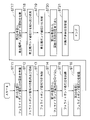
- FIG. 10 shows the distribution of the surface magnetic flux density of the rotor 1 according to the first embodiment, the distribution of the surface magnetic flux density of the rotor 101a according to the first comparative example, and the distribution of the surface magnetic flux density of the rotor 101b according to the second comparative example.
- the horizontal axis indicates the position [degrees] in the circumferential direction C on the outer peripheries 1c, 101c, 101d of the rotors 1, 101a, 101b
- the vertical axis indicates the surface magnetic flux density [a.u. ] is shown.
- the solid line represents the waveform W1 of the surface magnetic flux density distribution of the rotor 1 according to the first embodiment.
- FIG. 10 shows the distribution of the surface magnetic flux density of the rotor 1 according to the first embodiment, the distribution of the surface magnetic flux density of the rotor 101a according to the first comparative example, and the distribution of the surface magnetic flux density of the rotor 101b according to the second comparative example.
- the horizontal axis indicates the
- the dashed line indicates the waveform W2 of the surface magnetic flux density distribution of the rotor 101a according to Comparative Example 1
- the dashed line indicates the waveform W3 of the surface magnetic flux density distribution of the rotor 101b according to Comparative Example 2.
- the waveform W3 is a sinusoidal waveform.
- changes in the surface magnetic flux density in the circumferential direction C are uniform.
- waveform W2 is less smooth than waveform W3.
- the change in surface magnetic flux density is not uniform in the rotor 101b.
- distortion occurs in the inter-electrode portion of the rotor 1 in the waveform W2.
- the waveform W1 has a shape more similar to a sine wave than the waveform W2.
- the direction of the oriented magnetic field in ferrite bonded magnet 20 and the direction of the oriented magnetic field in rare earth bonded magnet 31 are different from each other.
- the magnetic flux of the ferrite bonded magnet 20 is concentrated at and near the magnetic boundary between the ferrite bonded magnet 20 and the rare earth bonded magnet 31, and the surface magnetic flux density at and near the magnetic boundary increases. Therefore, it is possible to suppress the occurrence of distortion of the effective magnetic flux interlinking with the stator core 61 (see FIG. 3) in the interpolar portion of the rotor 1 .
- first magnetic lines of force M1 and the second magnetic lines of force M2 will be described.
- the curvature of first magnetic force line M1 in the xy plane is the same as the curvature of second magnetic force line M2. greater than This makes it easier for the first magnetic lines of force M1 to be oriented in the radial direction in the interpolar portion of the rotor 1 .
- the difference between the surface magnetic flux density at the center of the pole of the rotor 1 and the surface magnetic flux density at the inter-polar part becomes small, so that the waveform W1 of the surface magnetic flux density of the rotor 1 approximates the waveform W3 of a sine wave ( See Figure 10). Therefore, it is possible to suppress the occurrence of distortion of the effective magnetic flux.
- the cost of the rotor 1 according to Embodiment 1 will be explained in comparison with the rotor 101b according to Comparative Example 2.
- the entire outer circumference 101d of the rotor 101b is composed of the rare earth bonded magnets 130b.
- the outer periphery 1c of the rotor 1 is formed by the outer periphery 20c of the ferrite bonded magnet 20 and the outer periphery 31c of each of the plurality of rare earth bonded magnets 31.
- the amount of rare earth bonded magnets 31 used can be reduced compared to rotor 101b.
- the amount of rare earth bonded magnets 31 used can be reduced by about 20% compared to rotor 101b.
- the rare earth bonded magnet 31 is more expensive than the ferrite bonded magnet 20 .
- the material unit price of the rare earth bonded magnet 31 is ten times or more the material unit price of the ferrite bonded magnet 20 . Therefore, since the outer circumference 1c of the rotor 1 is composed of the outer circumference 20c of the ferrite bonded magnet 20 and the outer circumference 31c of the rare earth bonded magnet 31, the amount of rare earth bonded magnet 31 used can be reduced. Therefore, according to Embodiment 1, the cost of the rotor 1 can be reduced.
- FIG. 11 is a flow chart showing the manufacturing process of the rotor 1. As shown in FIG. A magnetizer is used in the manufacturing process of the rotor 1 .
- step ST1 the rotor main body 50 is formed. Details of step ST1 will be described later.
- step ST2 the rotor main body 50 is connected to the shaft 10.
- the rotor main body 50 is connected to the shaft 10 by integrating the rotor main body 50 and the shaft 10 via the resin portion 7 .
- step ST3 for example, the rotor main body 50 is magnetized using a magnetizer.
- FIG. 12 is a flow chart showing the steps for forming the rotor body 50 shown in FIGS.
- a first mold for molding the ferrite bonded magnet 20 a second mold for molding the rare earth bonded magnet 31, a magnet for magnetic field orientation, and a An iron core is used.
- step ST11 the inside of the first mold for molding the ferrite bond magnet 20 is filled with the raw material of the ferrite bond magnet 20.
- the ferrite bond magnet 20 is molded by injection molding, for example. Note that the ferrite bond magnet 20 may be molded by other molding methods such as press molding instead of injection molding.
- step ST12 while orienting the ferrite bond magnet 20, the ferrite bond magnet 20 having a predetermined shape is molded.
- an orientation core for orientation specifically, an orientation core 91 shown in FIG. 15 to be described later
- an orientation magnet for orientation specifically, an orientation magnet 81 shown in FIG. 15 to be described later
- a bonded ferrite magnet 20 having a polar anisotropic orientation is formed.
- the ferrite bond magnet 20 is magnetized so that the surface magnetic flux density between the plurality of grooves 22 increases as it approaches the side surface 22b. That is, the ferrite bonded magnet 20 is polar anisotropically oriented so that the surface magnetic flux density is maximized at the outer periphery of the boundary between the ferrite bonded magnet 20 and the rare earth bonded magnet 31 . Details of the method for orienting the ferrite bond magnet 20 will be described later.
- step ST13 the formed ferrite bond magnet 20 is cooled.
- the ferrite bond magnet 20 is taken out from the first mold.
- step ST15 the ferrite bond magnet 20 taken out is demagnetized.
- step ST16 the ferrite bond magnet 20 is placed inside the second mold for injection molding the rare earth bond magnet 31.
- step ST17 the raw material of the rare earth bonded magnet 31 is filled into the groove 22 of the ferrite bonded magnet 20 placed in the second mold.
- Rare-earth bonded magnet 31 is formed by, for example, injection molding. Note that the rare earth bonded magnet 31 may be molded by other molding methods such as press molding instead of injection molding.
- step ST18 while orienting the raw material of rare earth bonded magnet 31, rare earth bonded magnet 31 having a predetermined shape is formed.
- an orientation iron core for magnetic field orientation specifically, an orientation iron core 92 shown in FIG. 16 to be described later
- a magnet for magnetic field orientation specifically, an orientation magnet shown in FIG. 16 to be described later
- the rotor main body 50 in which the ferrite bond magnet 20 and the plurality of rare earth bond magnets 31 are integrally formed can be formed.
- step ST19 the rotor main body 50 formed in step ST18 is cooled.
- step ST20 the cooled rotor main body 50 is taken out from the second mold.
- step ST21 the rotor body 50 taken out in step ST20 is demagnetized.
- FIG. 13 is a schematic diagram showing the first magnetic lines of force M1 of the ferrite bond magnet 20 magnetized in step ST12 shown in FIG.
- FIG. 14 is a schematic diagram showing second magnetic lines of force M2 of rare earth bonded magnet 31 magnetized in step ST18 shown in FIG.
- the N pole rare earth bonded magnet 31 is denoted by 31n
- the S pole rare earth bonded magnet 31 is denoted by 31s.
- the ferrite bond magnet 20 is magnetized so that the direction of the first magnetic force line M1 of the rare earth bond magnet 31 is aligned with the direction of the second magnetic force line M2.
- FIG. 15 is a schematic diagram showing an oriented magnet 81 and an oriented iron core 91 for forming the ferrite bond magnet 20.
- the oriented magnet 81 and the plurality of oriented iron cores 91 are arranged in a mold (not shown).
- the multiple oriented cores 91 are arranged in the circumferential direction C at regular intervals.
- the oriented magnet 81 and the plurality of oriented iron cores 91 form a magnetic circuit for applying a polar anisotropic oriented magnetic field B1.
- the tip portion 91a of the oriented core 91 is branched in the circumferential direction C from the outer side to the inner side in the radial direction.
- Tip portion 91 a of oriented iron core 91 is arranged to face portion 23 between groove portions 22 adjacent in circumferential direction C of ferrite bond magnet 20 .
- the tip 91a of the oriented iron core 91 can be arranged close to the boundary between the ferrite bonded magnet 20 and the rare earth bonded magnet 31 (that is, the side surface 22b of the groove 22) and its vicinity. Therefore, the curvature of the first magnetic lines of force M1 of the ferrite bond magnet 20 in the xy plane can be increased. In other words, according to Embodiment 1, the first magnetic lines of force M1 of ferrite bond magnet 20 tend to be directed outward in the radial direction.
- FIG. 16 is a schematic diagram showing an oriented magnet 81 and an oriented iron core 92 for forming the rare earth bonded magnet 31.
- an orienting magnet 81 which is a magnet for magnetic field orientation
- a plurality of orienting cores 92 which are iron cores for magnetic field orientation
- the oriented magnets 81 and the oriented iron cores 92 are arranged in a mold (not shown).
- the plurality of oriented cores 92 are arranged at predetermined intervals.
- the oriented magnet 81 and the plurality of oriented iron cores 92 form a magnetic circuit for applying a polar anisotropic oriented magnetic field B2.
- a radially inner end portion 92a of the oriented core 92 faces the central portion of the rare earth bond magnet 31 in the circumferential direction C, unlike the end portion 91a of the oriented core 91 shown in FIG. As a result, the magnetic flux can be concentrated in the central portion in the circumferential direction C of the rare earth bonded magnet 31, which is the central portion of the pole.
- FIG. 17(A) is a plan view showing a portion of the rotor 1 according to Embodiment 1 and the lines of magnetic force M1 and M2 in the portion.
- FIG. 17(B) is an enlarged plan view showing magnetic lines of force M1 and M2 at the E portion shown in FIG. 17(A).
- 17A and 17B let D be a straight line that connects the axis A and the side surface 22b of the groove 22.
- the angle ⁇ formed between the straight line D and the first magnetic force line M1 of the ferrite bond magnet 20 is smaller than the angle ⁇ formed between the straight line D and the second magnetic force line M2 of the rare earth bond magnet 31 .
- the oriented magnetic field of the ferrite bond magnet 20 can be concentrated on the side surface 22b of the groove 22, which is the boundary, and the surface magnetic flux density in the interpolar portion of the rotor 1 can be increased. Therefore, since the waveform W1 of the distribution of the surface magnetic flux density of the rotor 1 approximates the waveform W3 of the sine wave (see FIG. 10), the occurrence of distortion of the effective magnetic flux interlinking with the stator core 61 (see FIG. 3) can be suppressed. can be suppressed.
- the direction of the first magnetic lines of force M1 formed by the adjacent magnetic poles of the ferrite bonded magnet 20 is aligned with the direction of the second magnetic lines of force M2 of the rare earth bonded magnets 31 adjacent in the circumferential direction C. different.
- the curvature of the first magnetic force line M1 in the xy plane is greater than the curvature of the second magnetic force line M2. small.
- the oriented magnetic field of the ferrite bond magnet 20 can be concentrated on the side surface 22b of the groove portion 22, which is the boundary portion.
- the waveform W1 of the distribution of the surface magnetic flux density of the rotor 1 approximates the waveform W3 of the sine wave, the generation of distortion of the effective magnetic flux interlinking with the stator core 61 can be suppressed. Therefore, in the rotor 1, it is possible to suppress the occurrence of distortion of the effective magnetic flux while reducing the cost.
- the magnetic flux of the magnetic flux flowing into the stator core 61 from the interpolar portion of the rotor 1 that is, the portion 23 between the grooves 22 adjacent to each other in the circumferential direction C of the ferrite bond magnet 20) amount can be increased.
- the angle ⁇ formed by the straight line D and the first magnetic force line M1 of the ferrite bond magnet 20 is the straight line D and the second magnetic line of force M2 of the rare earth bonded magnet 31 is smaller than the angle ⁇ .
- the oriented magnetic field of ferrite bonded magnet 20 can be concentrated at least in the vicinity of the magnetic boundary between ferrite bonded magnet 20 and rare earth bonded magnet 31 (specifically, side surface 22b of groove 22). Therefore, since the waveform W1 of the distribution of the surface magnetic flux density of the rotor 1 approximates the waveform W3 of the sine wave, it is possible to suppress the occurrence of distortion of the effective magnetic flux.
- oriented core 91 for magnetic field orientation of ferrite bonded magnet 20 is arranged so as to face the boundary between ferrite bonded magnet 20 and rare earth bonded magnet 31 .
- the oriented magnetic field of ferrite bonded magnet 20 can be concentrated at least in the vicinity of the magnetic boundary between ferrite bonded magnet 20 and rare earth bonded magnet 31 . Therefore, since the waveform W1 of the distribution of the surface magnetic flux density of the rotor 1 approximates the waveform W3 of the sine wave, it is possible to suppress the occurrence of distortion of the effective magnetic flux.
- electric motor 100 has rotor 1 and stator 6 .
- the rotor 1 can suppress the occurrence of distortion of the effective magnetic flux. Therefore, by including the rotor 1 in the electric motor 100 , it is possible to suppress a decrease in the output of the electric motor 100 .
- FIG. 18 is a diagram schematically showing the configuration of fan 200 according to the second embodiment.
- blower 200 has electric motor 100 and fan 201 as an impeller driven by electric motor 100 .
- Fan 201 is attached to shaft 10 of electric motor 100 (see FIG. 1, for example).
- the blower 200 is used, for example, as an outdoor blower for an outdoor unit 320 of an air conditioner 300 shown in FIG. 19 to be described later.
- fan 201 is, for example, a propeller fan.
- blower 200 has electric motor 100 described in the first embodiment. As described above, in the electric motor 100, the decrease in output is suppressed, so in the blower 200 having the electric motor 100, it is possible to suppress the decrease in the output.
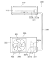
- FIG. 19 is a diagram schematically showing the configuration of an air conditioner 300 according to Embodiment 3. As shown in FIG.
- the air conditioner 300 has an indoor unit 310, an outdoor unit 320, and refrigerant pipes 330.
- the indoor unit 310 and the outdoor unit 320 are connected by a refrigerant pipe 330 to form a refrigerant circuit in which refrigerant circulates.
- the air conditioner 300 can operate, for example, a cooling operation in which cold air is blown from the indoor unit 310 or a heating operation in which warm air is blown.
- the indoor unit 310 has an indoor fan 311 and a housing 312 that accommodates the indoor fan 311 .
- the indoor fan 311 has an electric motor 311a and a fan 311b driven by the electric motor 311a.
- the fan 311b is attached to the shaft of the electric motor 311a. Rotation of the shaft of the electric motor 311a rotates the fan 311b to generate airflow.
- Fan 311b is, for example, a cross-flow fan.
- the outdoor unit 320 has a fan 200 as an outdoor fan, a compressor 321, and a housing 322 that accommodates the fan 200 and the compressor 321.
- the compressor 321 has a compression mechanism portion 321a that compresses refrigerant and an electric motor 321b that drives the compression mechanism portion 321a.
- the compression mechanism portion 321a and the electric motor 321b are connected to each other by a rotating shaft 321c.
- Electric motor 321b of compressor 321 may be electric motor 100 according to the first embodiment.
- the outdoor unit 320 further has a four-way valve (not shown) that switches the flow direction of the refrigerant.
- the four-way valve of the outdoor unit 320 allows the high-temperature, high-pressure refrigerant gas delivered from the compressor 321 to flow through the heat exchanger of the outdoor unit 320 during cooling operation, and through the heat exchanger of the indoor unit 310 during heating operation.
- the fan 200 according to Embodiment 2 may be used not only as the outdoor fan of the outdoor unit 320 but also as the indoor fan 311 described above.
- the blower 200 may be provided not only in the air conditioner 300 but also in other electrical equipment.
- the air conditioner 300 has the blower 200 described in the second embodiment. As described above, since the output of the fan 200 is suppressed from being lowered, the output of the air conditioner 300 having the fan 200 can also be suppressed from being lowered.
Landscapes
- Engineering & Computer Science (AREA)
- Power Engineering (AREA)
- Permanent Field Magnets Of Synchronous Machinery (AREA)
Priority Applications (2)
| Application Number | Priority Date | Filing Date | Title |
|---|---|---|---|
| JP2023548053A JPWO2023042366A1 (https=) | 2021-09-17 | 2021-09-17 | |
| PCT/JP2021/034255 WO2023042366A1 (ja) | 2021-09-17 | 2021-09-17 | 回転子、電動機、送風機、空気調和装置、及び回転子の製造方法 |
Applications Claiming Priority (1)
| Application Number | Priority Date | Filing Date | Title |
|---|---|---|---|
| PCT/JP2021/034255 WO2023042366A1 (ja) | 2021-09-17 | 2021-09-17 | 回転子、電動機、送風機、空気調和装置、及び回転子の製造方法 |
Publications (1)
| Publication Number | Publication Date |
|---|---|
| WO2023042366A1 true WO2023042366A1 (ja) | 2023-03-23 |
Family
ID=85602588
Family Applications (1)
| Application Number | Title | Priority Date | Filing Date |
|---|---|---|---|
| PCT/JP2021/034255 Ceased WO2023042366A1 (ja) | 2021-09-17 | 2021-09-17 | 回転子、電動機、送風機、空気調和装置、及び回転子の製造方法 |
Country Status (2)
| Country | Link |
|---|---|
| JP (1) | JPWO2023042366A1 (https=) |
| WO (1) | WO2023042366A1 (https=) |
Cited By (1)
| Publication number | Priority date | Publication date | Assignee | Title |
|---|---|---|---|---|
| JP7791473B1 (ja) * | 2024-09-27 | 2025-12-24 | ダイキン工業株式会社 | ボンド磁石の製造方法、ロータ、モータ、送風機、および、冷凍装置 |
Citations (4)
| Publication number | Priority date | Publication date | Assignee | Title |
|---|---|---|---|---|
| JPH0638478A (ja) * | 1992-07-21 | 1994-02-10 | Victor Co Of Japan Ltd | 電動機用マグネット及びその製造方法 |
| JP2005045978A (ja) * | 2003-07-25 | 2005-02-17 | Favess Co Ltd | モータ |
| JP2012228072A (ja) * | 2011-04-20 | 2012-11-15 | Mitsubishi Electric Corp | 永久磁石型回転電機およびその製造方法 |
| WO2020129123A1 (ja) * | 2018-12-17 | 2020-06-25 | 三菱電機株式会社 | 回転子、電動機、送風機、及び空気調和機、並びに回転子の製造方法 |
Family Cites Families (1)
| Publication number | Priority date | Publication date | Assignee | Title |
|---|---|---|---|---|
| WO2020261420A1 (ja) * | 2019-06-26 | 2020-12-30 | 三菱電機株式会社 | 回転子、電動機、送風機、空気調和機、及び回転子の製造方法 |
-
2021
- 2021-09-17 WO PCT/JP2021/034255 patent/WO2023042366A1/ja not_active Ceased
- 2021-09-17 JP JP2023548053A patent/JPWO2023042366A1/ja active Pending
Patent Citations (4)
| Publication number | Priority date | Publication date | Assignee | Title |
|---|---|---|---|---|
| JPH0638478A (ja) * | 1992-07-21 | 1994-02-10 | Victor Co Of Japan Ltd | 電動機用マグネット及びその製造方法 |
| JP2005045978A (ja) * | 2003-07-25 | 2005-02-17 | Favess Co Ltd | モータ |
| JP2012228072A (ja) * | 2011-04-20 | 2012-11-15 | Mitsubishi Electric Corp | 永久磁石型回転電機およびその製造方法 |
| WO2020129123A1 (ja) * | 2018-12-17 | 2020-06-25 | 三菱電機株式会社 | 回転子、電動機、送風機、及び空気調和機、並びに回転子の製造方法 |
Cited By (2)
| Publication number | Priority date | Publication date | Assignee | Title |
|---|---|---|---|---|
| JP7791473B1 (ja) * | 2024-09-27 | 2025-12-24 | ダイキン工業株式会社 | ボンド磁石の製造方法、ロータ、モータ、送風機、および、冷凍装置 |
| WO2026070735A1 (ja) * | 2024-09-27 | 2026-04-02 | ダイキン工業株式会社 | ボンド磁石の製造方法、ロータ、モータ、送風機、および、冷凍装置 |
Also Published As
| Publication number | Publication date |
|---|---|
| JPWO2023042366A1 (https=) | 2023-03-23 |
Similar Documents
| Publication | Publication Date | Title |
|---|---|---|
| CN101803157B (zh) | 永磁旋转电机 | |
| US20110241467A1 (en) | Permanent magnet motor | |
| JP7072726B2 (ja) | 回転子、電動機、送風機、空気調和機、及び回転子の製造方法 | |
| AU2018453979B2 (en) | Rotor, electric motor, fan, air conditioner, and method for manufacturing rotor | |
| WO2018066084A1 (ja) | 電動機および空気調和装置 | |
| WO2023042366A1 (ja) | 回転子、電動機、送風機、空気調和装置、及び回転子の製造方法 | |
| US20250211043A1 (en) | Motor, blower, and air conditioner | |
| JP7442688B2 (ja) | 回転子、電動機、送風機及び空気調和装置 | |
| JP7130051B2 (ja) | 回転子、電動機、圧縮機、及び冷凍空調装置 | |
| US20230216360A1 (en) | Electric motor, compressor, blower, refrigerator | |
| JPWO2023195076A5 (https=) | ||
| US20230246492A1 (en) | Compressor | |
| JP7098047B2 (ja) | モータ、ファン、および空気調和機 | |
| US20220376568A1 (en) | Rotor, electric motor, fan, and air conditioner | |
| JP7415024B2 (ja) | 電動機、送風機及び空気調和装置 | |
| WO2023144919A1 (ja) | 回転子、電動機、送風機及び空気調和装置 | |
| JP7531692B2 (ja) | 回転子、電動機、送風機及び空気調和装置 | |
| JPWO2023042366A5 (https=) | ||
| JP7026805B2 (ja) | ステータ、モータ、ファン、及び空気調和機並びにステータの製造方法 | |
| JP7791473B1 (ja) | ボンド磁石の製造方法、ロータ、モータ、送風機、および、冷凍装置 | |
| US20230378829A1 (en) | Rotor, motor, blower, air conditioner, and manufacturing method of rotor | |
| WO2024100869A1 (ja) | 回転子、電動機、ファン、及び空気調和機 |
Legal Events
| Date | Code | Title | Description |
|---|---|---|---|
| 121 | Ep: the epo has been informed by wipo that ep was designated in this application |
Ref document number: 21957547 Country of ref document: EP Kind code of ref document: A1 |
|
| WWE | Wipo information: entry into national phase |
Ref document number: 2023548053 Country of ref document: JP |
|
| NENP | Non-entry into the national phase |
Ref country code: DE |
|
| 122 | Ep: pct application non-entry in european phase |
Ref document number: 21957547 Country of ref document: EP Kind code of ref document: A1 |