WO2023032321A1 - 情報処理装置、情報処理方法及びプログラム - Google Patents
情報処理装置、情報処理方法及びプログラム Download PDFInfo
- Publication number
- WO2023032321A1 WO2023032321A1 PCT/JP2022/013402 JP2022013402W WO2023032321A1 WO 2023032321 A1 WO2023032321 A1 WO 2023032321A1 JP 2022013402 W JP2022013402 W JP 2022013402W WO 2023032321 A1 WO2023032321 A1 WO 2023032321A1
- Authority
- WO
- WIPO (PCT)
- Prior art keywords
- user
- information processing
- information
- human
- area
- Prior art date
- Legal status (The legal status is an assumption and is not a legal conclusion. Google has not performed a legal analysis and makes no representation as to the accuracy of the status listed.)
- Ceased
Links
Images













Classifications
-
- G—PHYSICS
- G01—MEASURING; TESTING
- G01B—MEASURING LENGTH, THICKNESS OR SIMILAR LINEAR DIMENSIONS; MEASURING ANGLES; MEASURING AREAS; MEASURING IRREGULARITIES OF SURFACES OR CONTOURS
- G01B11/00—Measuring arrangements characterised by the use of optical techniques
- G01B11/24—Measuring arrangements characterised by the use of optical techniques for measuring contours or curvatures
-
- G—PHYSICS
- G06—COMPUTING OR CALCULATING; COUNTING
- G06V—IMAGE OR VIDEO RECOGNITION OR UNDERSTANDING
- G06V10/00—Arrangements for image or video recognition or understanding
- G06V10/20—Image preprocessing
- G06V10/25—Determination of region of interest [ROI] or a volume of interest [VOI]
-
- A—HUMAN NECESSITIES
- A63—SPORTS; GAMES; AMUSEMENTS
- A63F—CARD, BOARD, OR ROULETTE GAMES; INDOOR GAMES USING SMALL MOVING PLAYING BODIES; VIDEO GAMES; GAMES NOT OTHERWISE PROVIDED FOR
- A63F13/00—Video games, i.e. games using an electronically generated display having two or more dimensions
- A63F13/20—Input arrangements for video game devices
- A63F13/21—Input arrangements for video game devices characterised by their sensors, purposes or types
- A63F13/212—Input arrangements for video game devices characterised by their sensors, purposes or types using sensors worn by the player, e.g. for measuring heart beat or leg activity
-
- A—HUMAN NECESSITIES
- A63—SPORTS; GAMES; AMUSEMENTS
- A63F—CARD, BOARD, OR ROULETTE GAMES; INDOOR GAMES USING SMALL MOVING PLAYING BODIES; VIDEO GAMES; GAMES NOT OTHERWISE PROVIDED FOR
- A63F13/00—Video games, i.e. games using an electronically generated display having two or more dimensions
- A63F13/20—Input arrangements for video game devices
- A63F13/21—Input arrangements for video game devices characterised by their sensors, purposes or types
- A63F13/213—Input arrangements for video game devices characterised by their sensors, purposes or types comprising photodetecting means, e.g. cameras, photodiodes or infrared cells
-
- A—HUMAN NECESSITIES
- A63—SPORTS; GAMES; AMUSEMENTS
- A63F—CARD, BOARD, OR ROULETTE GAMES; INDOOR GAMES USING SMALL MOVING PLAYING BODIES; VIDEO GAMES; GAMES NOT OTHERWISE PROVIDED FOR
- A63F13/00—Video games, i.e. games using an electronically generated display having two or more dimensions
- A63F13/25—Output arrangements for video game devices
-
- A—HUMAN NECESSITIES
- A63—SPORTS; GAMES; AMUSEMENTS
- A63F—CARD, BOARD, OR ROULETTE GAMES; INDOOR GAMES USING SMALL MOVING PLAYING BODIES; VIDEO GAMES; GAMES NOT OTHERWISE PROVIDED FOR
- A63F13/00—Video games, i.e. games using an electronically generated display having two or more dimensions
- A63F13/70—Game security or game management aspects
-
- G—PHYSICS
- G06—COMPUTING OR CALCULATING; COUNTING
- G06F—ELECTRIC DIGITAL DATA PROCESSING
- G06F3/00—Input arrangements for transferring data to be processed into a form capable of being handled by the computer; Output arrangements for transferring data from processing unit to output unit, e.g. interface arrangements
- G06F3/01—Input arrangements or combined input and output arrangements for interaction between user and computer
- G06F3/011—Arrangements for interaction with the human body, e.g. for user immersion in virtual reality
-
- G—PHYSICS
- G06—COMPUTING OR CALCULATING; COUNTING
- G06F—ELECTRIC DIGITAL DATA PROCESSING
- G06F3/00—Input arrangements for transferring data to be processed into a form capable of being handled by the computer; Output arrangements for transferring data from processing unit to output unit, e.g. interface arrangements
- G06F3/01—Input arrangements or combined input and output arrangements for interaction between user and computer
- G06F3/011—Arrangements for interaction with the human body, e.g. for user immersion in virtual reality
- G06F3/012—Head tracking input arrangements
-
- G—PHYSICS
- G06—COMPUTING OR CALCULATING; COUNTING
- G06T—IMAGE DATA PROCESSING OR GENERATION, IN GENERAL
- G06T7/00—Image analysis
- G06T7/50—Depth or shape recovery
-
- G—PHYSICS
- G06—COMPUTING OR CALCULATING; COUNTING
- G06T—IMAGE DATA PROCESSING OR GENERATION, IN GENERAL
- G06T7/00—Image analysis
- G06T7/70—Determining position or orientation of objects or cameras
- G06T7/73—Determining position or orientation of objects or cameras using feature-based methods
-
- G—PHYSICS
- G06—COMPUTING OR CALCULATING; COUNTING
- G06V—IMAGE OR VIDEO RECOGNITION OR UNDERSTANDING
- G06V20/00—Scenes; Scene-specific elements
- G06V20/20—Scenes; Scene-specific elements in augmented reality scenes
-
- G—PHYSICS
- G06—COMPUTING OR CALCULATING; COUNTING
- G06V—IMAGE OR VIDEO RECOGNITION OR UNDERSTANDING
- G06V40/00—Recognition of biometric, human-related or animal-related patterns in image or video data
- G06V40/10—Human or animal bodies, e.g. vehicle occupants or pedestrians; Body parts, e.g. hands
- G06V40/103—Static body considered as a whole, e.g. static pedestrian or occupant recognition
-
- A—HUMAN NECESSITIES
- A63—SPORTS; GAMES; AMUSEMENTS
- A63F—CARD, BOARD, OR ROULETTE GAMES; INDOOR GAMES USING SMALL MOVING PLAYING BODIES; VIDEO GAMES; GAMES NOT OTHERWISE PROVIDED FOR
- A63F2300/00—Features of games using an electronically generated display having two or more dimensions, e.g. on a television screen, showing representations related to the game
- A63F2300/80—Features of games using an electronically generated display having two or more dimensions, e.g. on a television screen, showing representations related to the game specially adapted for executing a specific type of game
- A63F2300/8082—Virtual reality
-
- G—PHYSICS
- G06—COMPUTING OR CALCULATING; COUNTING
- G06T—IMAGE DATA PROCESSING OR GENERATION, IN GENERAL
- G06T2207/00—Indexing scheme for image analysis or image enhancement
- G06T2207/10—Image acquisition modality
- G06T2207/10028—Range image; Depth image; 3D point clouds
-
- G—PHYSICS
- G06—COMPUTING OR CALCULATING; COUNTING
- G06T—IMAGE DATA PROCESSING OR GENERATION, IN GENERAL
- G06T2207/00—Indexing scheme for image analysis or image enhancement
- G06T2207/20—Special algorithmic details
- G06T2207/20036—Morphological image processing
- G06T2207/20044—Skeletonization; Medial axis transform
Definitions
- the present disclosure relates to an information processing device, an information processing method, and a program.
- a technology is known that uses AR (Augment Reality) or VR (Virtual Reality) to display an image rendered by a rendering device on, for example, a head-mounted display (HMD) worn by a user.
- AR Augment Reality
- VR Virtual Reality
- Such a technique includes, for example, the technique described in Patent Document 1 below.
- information about the real environment is acquired in order to place the content in an appropriate position.
- information about the real environment is acquired in order to set a region (play area) in which the user can safely move.
- the system acquires information about the real environment, such as obstacles, from the sensors mounted on the HMD (Head Mounted Display). At this time, for example, if the user is captured in the camera and the sensor detects the user, the system may erroneously detect the user as an obstacle.
- the sensors mounted on the HMD Head Mounted Display
- the area where content can be placed may be limited, or the play area may be set smaller than it actually is.
- an information processing device includes a control unit. Based on a user posture estimated using a sensor mounted on a device used by a user, a control unit determines distance information generated based on a distance measuring device mounted on the device, including the user. Estimate the area. The control unit updates environment information around the user based on the human area and the distance information.
- FIG. 1 is a diagram for explaining an overview of an information processing system according to the present disclosure
- FIG. FIG. 4 is a diagram for explaining an example of setting a play area
- FIG. It is a figure for demonstrating an example of a user's erroneous detection.
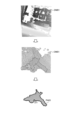
- 1 is a diagram for explaining an overview of an information processing method by an information processing system according to the present disclosure
- FIG. 1 is a block diagram showing a configuration example of a terminal device according to an embodiment of the present disclosure
- FIG. 1 is a block diagram showing a configuration example of an information processing device according to an embodiment of the present disclosure
- FIG. It is a figure which shows an example of the depth map which the estimation process part which concerns on embodiment of this indication acquires.
- FIG. 4 is a diagram showing an example of a ranging area of a depth map by a terminal device according to an embodiment of the present disclosure
- FIG. FIG. 5 is a diagram for explaining reflection of a user according to the embodiment of the present disclosure
- FIG. FIG. 4 is a diagram for explaining the length of the human region according to the embodiment of the present disclosure
- FIG. FIG. 4 is a diagram for explaining the length of the human region according to the embodiment of the present disclosure
- FIG. FIG. 4 is a diagram for explaining the width of the human region according to the embodiment of the present disclosure
- FIG. FIG. 4 is a diagram for explaining the width of the human region according to the embodiment of the present disclosure
- FIG. FIG. 4 is a diagram for explaining the width of the human region according to the embodiment of the present disclosure
- FIG. 4 is a chart showing an example of a human region confidence value table according to an embodiment of the present disclosure
- FIG. FIG. 4 is a diagram for explaining an example of a human region according to an embodiment of the present disclosure
- FIG. FIG. 4 is a diagram for explaining an example of a human region according to an embodiment of the present disclosure
- FIG. FIG. 3 is a diagram showing an example of information processing according to an embodiment of the present disclosure
- FIG. FIG. 4 is a diagram showing an example of Occupancy Map generation processing according to an embodiment of the present disclosure
- FIG. 11 is a diagram for explaining a user's posture according to the first modified example of the embodiment of the present disclosure
- FIG. 11 is a diagram for explaining an example of human region correction according to the first modification of the embodiment of the present disclosure
- FIG. 10 is a diagram showing an example of Occupancy Map generation processing according to the first modified example of the embodiment of the present disclosure
- FIG. 11 is a diagram for explaining a user's posture according to a second modified example of the embodiment of the present disclosure
- FIG. FIG. 11 is a diagram for explaining a human region according to a third modified example of the embodiment of the present disclosure
- FIG. FIG. 11 is a diagram for explaining an example of detection of a human region according to the third modified example of the embodiment of the present disclosure
- FIG. FIG. 11 is a diagram for explaining an example of detection of a human region according to the third modified example of the embodiment of the present disclosure
- FIG. FIG. 11 is a diagram for explaining an example of detection of a human region according to the third modified example of the embodiment of the present disclosure
- FIG. 12 is a diagram showing an example of Occupancy Map generation processing according to the third modified example of the embodiment of the present disclosure
- FIG. 13 is a diagram showing an example of an environment Occupancy Map according to the fourth modified example of the embodiment of the present disclosure
- FIG. 12 is a diagram showing an example of a human area Occupancy Map according to the fourth modified example of the embodiment of the present disclosure
- FIG. 13 is a diagram showing an example of an Occupancy Map according to the fourth modified example of the embodiment of the present disclosure
- FIG. 14 is a diagram showing an example of Occupancy Map generation processing according to the fourth modified example of the embodiment of the present disclosure
- FIG. 21 is a diagram for explaining a plane region according to a fifth modified example of the embodiment of the present disclosure
- FIG. 20 is a diagram showing an example of a plane detection map according to a fifth modified example of the embodiment of the present disclosure
- FIG. 14 is a diagram showing an example of Occupancy Map generation processing according to the fifth modified example of the embodiment of the present disclosure
- FIG. 16 is a flowchart showing an example of the flow of plane estimation processing according to the fifth modified example of the embodiment of the present disclosure
- FIG. 1 is a hardware configuration diagram showing an example of a computer that implements functions of an information processing apparatus according to an embodiment of the present disclosure
- FIG. 1 is a diagram for explaining an outline of an information processing system 1 according to the present disclosure. As shown in FIG. 1 , the information processing system 1 includes an information processing device 100 and a terminal device 200 .
- the information processing device 100 and the terminal device 200 can communicate with each other via various wired or wireless networks. Any communication method can be applied to the network, regardless of whether it is wired or wireless (for example, WiFi (registered trademark), Bluetooth (registered trademark), etc.).
- the number of information processing devices 100 and terminal devices 200 included in the information processing system 1 is not limited to the number illustrated in FIG. 1, and may be included in a greater number.
- FIG. 1 illustrates a case where the information processing system 1 has the information processing device 100 and the terminal device 200 individually, the present invention is not limited to this.
- the information processing device 100 and the terminal device 200 may be implemented as one device.
- a single device such as a stand-alone HMD can implement the functions of both the information processing device 100 and the terminal device 200 .
- the terminal device 200 is a wearable device (eyewear device) such as a glasses-type HMD worn by the user U on the head.
- eyewear device such as a glasses-type HMD worn by the user U on the head.
- the eyewear device applicable as the terminal device 200 may be a so-called see-through type head-mounted display (AR (Augmented Reality) glasses) that transmits an image in real space, or may transmit an image in real space. It may be of a goggle type (VR (Virtual Reality) goggles).
- AR Augmented Reality
- VR Virtual Reality
- the terminal device 200 is not limited to being an HMD, and may be a tablet, smartphone, or the like held by the user U, for example.
- the information processing device 100 comprehensively controls the operation of the terminal device 200 .
- the information processing device 100 is implemented by, for example, a processing circuit such as a CPU (Central Processing Unit) or a GPU (Graphics Processing Unit). A detailed configuration of the information processing apparatus 100 according to the present disclosure will be described later.
- the information processing apparatus 100 specifies a safe play area (permissible area) that does not come into contact with real objects, and controls the HMD so that the user U moves within the play area. Control.
- the area PA is identified as a play area where the user U can move and reach out without colliding with obstacles.
- the play area may be represented as a three-dimensional area such as a combination of a dotted line PA1 indicated on the floor and a wall PA2 vertically extending from the dotted line PA1.
- the play area may be represented as a two-dimensional area of dotted line PA1.
- the play area can be set as a two-dimensional area or a three-dimensional area.
- the user U designates the play area by drawing a boundary line using a device such as a game controller (not shown).
- the information processing system detects the position of the user U and sets a predetermined range within a radius of several meters around the user U as the play area.
- the conventional information processing system sets a predetermined range according to the position of the user U as the play area, the predetermined range includes obstacles, and the user U may collide with the obstacles. Furthermore, in this case, even if there is an area without obstacles outside the predetermined range, the conventional information processing system cannot set the area as a play area, which narrows the range in which the user U can move. There is fear.
- an information processing system that generates information (environmental information) on a three-dimensional space surrounding the user U and sets a play area.
- the environment information represents an object existing in a three-dimensional space using a plurality of planes or voxels (lattice).
- Environmental information includes, for example, an occupancy grid map, a 3D mesh, and the like.
- FIG. 2 is a diagram for explaining a setting example of the play area.
- the information processing system acquires distance information DM01 of objects in the surrounding environment from, for example, a distance measuring device mounted on the HMD worn by the user U.
- the distance information DM01 shown in the upper diagram of FIG. 2 is a depth map representing the distance from the distance measuring device to the object.
- the information processing system generates environment information OM01 based on distance information DM01.
- the information processing system generates an occupancy grid map (hereinafter also referred to as Occupancy Map) as the environment information OM01.
- Occupancy Map an occupancy grid map
- Occupancy Map is a well-known technique for representing an environment in 3D.
- the surrounding environment is expressed as a plurality of voxels arranged in a 3D grid in a 3D space.
- a plurality of voxels indicate occupancy/unoccupancy of an object by holding the following three states respectively.
- Occupied Indicates that the voxel is occupied by an object (occupied state).
- Free Indicates that the voxel is not occupied by an object and is an empty space (unoccupied state).
- Unknown Indicates that it cannot be determined whether or not the voxel is occupied by an object due to insufficient observation (unknown state).
- the method of generating the Occupancy Map is disclosed, for example, in reference [1].
- the information processing system estimates the existence probability of an object for each voxel from the time-series ranging information (distance information DM01 described above), and determines the state of each voxel.
- the information processing system sets the play area using the generated environment information OM01. As shown in the lower diagram of FIG. 2, the information processing system 1 detects the floor plane from the environment information OM01 and sets the floor plane as the play area PA01.
- the information processing system can set the play area PA01 in which the user U can move safely by acquiring the environment information OM01 around the user U.
- the information processing system can use the environment information OM01 for purposes other than setting the play area PA01.
- the information processing system can use the environment information OM01 to set the moving route and presentation position of the AI character (content) to be presented to the user U.
- the information processing system causes the AI character to avoid obstacles in the same manner as the user U moves. Therefore, the information processing system uses the environment information OM01 to calculate the moving route of the AI character.
- the user U may get into the distance information acquired by the information processing system.
- the feet of the user U may enter the distance measuring range of the distance measuring device (the circled portion in the upper diagram of FIG. 3). ).
- the information processing system generates environment information with the user U as an object (obstacle).
- the circled portion is the portion where the information processing system erroneously detects the user U as an obstacle.
- FIG. 3 is a diagram for explaining an example of erroneous detection of user U. In FIG.
- the information processing system sets a plane that does not include the user U as the play area. In this way, if the information processing system detects the user U as an obstacle, the accuracy of the environment information may be degraded, and the play area may not be set correctly.
- the information processing system 1 estimates a human area including the user U from the distance information based on the user's U posture.
- the information processing system 1 updates the environment information around the user U based on the estimated human area and distance information.
- FIG. 4 is a diagram for explaining an overview of the information processing method by the information processing system 1 according to the present disclosure.
- the information processing system 1 estimates a human area including the user U from the distance information. For example, the information processing system 1 sets the human area according to the orientation of the user U's face. At this time, the information processing system 1 can set a plurality of human regions R01 and R02 according to the distance from the user U, in other words, the distance from the HMD 200.
- FIG. 1 is a diagrammatic representation of the human area including the user U from the distance information. For example, the information processing system 1 sets the human area according to the orientation of the user U's face. At this time, the information processing system 1 can set a plurality of human regions R01 and R02 according to the distance from the user U, in other words, the distance from the HMD 200.
- the information processing system 1 sets a human area reliability value for the distance information included in the human areas R01 and R02. For example, when the distance information is a depth map, the information processing system 1 gives human region confidence values to pixels included in the human regions R01 and R02.
- the human area confidence value is, for example, a value indicating that the distance information is a person (user U). The greater the human area confidence value, the higher the possibility that the distance information is the distance to the user U.
- the information processing system 1 sets different human area reliability values for the areas R01 and R02.
- the information processing system 1 sets the human region confidence value such that the human region confidence value of the region R02 closer to the user U, in other words, the HMD 200, is greater than the human region confidence value of the region R01.
- the details of setting the human area reliability value will be described later.
- the information processing system 1 generates or updates environment information according to the set human region reliability value. Specifically, the information processing system 1 updates the environment information so that distance information (pixels of the depth map) with a large human region confidence value is not reflected in the environment information (voxels of the occupancy map). For example, when the information processing system 1 updates a voxel corresponding to a pixel that has a human region confidence value of “1”, in other words, that is most likely to be a human, the value (range measurement value) of the pixel is Update without using. The details of updating the environment information using the human area reliability value will be described later.
- the information processing system 1 can further reduce false detection of the user U. Therefore, as shown in the lower diagram of FIG. 4, the information processing system 1 can generate environment information in which the influence of the user U is further reduced.
- FIG. 5 is a block diagram showing a configuration example of the terminal device 200 according to the embodiment of the present disclosure. As shown in FIG. 5, the terminal device 200 includes a communication section 210, a sensor section 220, a display section 230, an input section 240, and a control section 250.
- the communication unit 210 transmits and receives information to and from another device.
- the communication unit 210 transmits a video reproduction request and a sensing result of the sensor unit 220 to the information processing apparatus 100 under the control of the control unit 250 .
- the communication unit 210 receives video to be reproduced from the information processing device 100 .
- the sensor unit 220 may include, for example, a camera (image sensor), depth sensor, microphone, acceleration sensor, gyroscope, geomagnetic sensor, GPS (Global Positioning System) receiver, and the like. Moreover, the sensor unit 220 may include a speed sensor, an acceleration sensor, an angular velocity sensor (gyro sensor), and an inertial measurement unit (IMU: Inertial Measurement Unit) integrating them.
- a camera image sensor
- depth sensor depth sensor
- microphone acceleration sensor
- acceleration sensor gyroscope
- geomagnetic sensor GPS (Global Positioning System) receiver
- GPS Global Positioning System
- IMU Inertial Measurement Unit
- the sensor unit 220 senses the position of the terminal device 200 in real space (or the position of the user U who uses the terminal device 200), the orientation and posture of the terminal device 200, or the acceleration. Further, the sensor unit 220 senses depth information around the terminal device 200 . If the sensor unit 220 includes a distance measuring device that senses depth information, the distance measuring device may be a stereo camera, a ToF (Time of Flight) distance image sensor, or the like.
- the distance measuring device may be a stereo camera, a ToF (Time of Flight) distance image sensor, or the like.
- Display unit 230 displays an image under the control of control unit 250 .
- the display 230 may have a right-eye display and a left-eye display (not shown).
- the right-eye display unit projects an image using at least a partial area of the right-eye lens (not shown) included in the terminal device 200 as a projection surface.
- the left-eye display unit projects an image using at least a partial area of a left-eye lens (not shown) included in the terminal device 200 as a projection surface.
- the display unit 230 can project an image using at least a partial area of the goggle-type lens as a projection plane.
- the left-eye lens and right-eye lens may be made of a transparent material such as resin or glass.
- the display unit 230 can be configured as a non-transmissive display device.
- the display unit 230 may be configured to include an LCD (Liquid Crystal Display) or an OLED (Organic Light Emitting Diode).
- LCD Liquid Crystal Display
- OLED Organic Light Emitting Diode
- Input unit 240 may include a touch panel, buttons, levers, switches, and the like.
- the input unit 240 receives various inputs from the user U. FIG. For example, when an AI character is placed in the virtual space, the input unit 240 can receive an input from the user U for changing the placement position of the AI character.
- Control unit 250 comprehensively controls the operation of the terminal device 200 using, for example, a CPU, a GPU (Graphics Processing Unit), and a RAM built in the terminal device 200 .
- the control unit 250 causes the display unit 230 to display an image received from the information processing device 100 .
- control unit 250 causes the display unit 230 to display a portion of the image corresponding to the position and orientation information of the terminal device 200 (or the user U or the like) sensed by the sensor unit 220 .
- the control unit 250 when the display unit 230 has a right-eye display unit and a left-eye display unit (not shown), the control unit 250 generates the right-eye image and the left-eye image based on the video received from the information processing device 100. . Then, the control unit 250 causes the right-eye display unit to display the right-eye image and the left-eye display unit to display the left-eye image. Thereby, the display unit 230 can allow the user U to view the stereoscopic video.
- control unit 250 can perform various recognition processes based on the sensing results of the sensor unit 220.
- control unit 250 can recognize actions of the user U wearing the terminal device 200 (eg, gestures of the user U, movement of the user U, etc.) based on the sensing result.
- FIG. 6 is a block diagram showing a configuration example of the information processing device 100 according to the embodiment of the present disclosure.
- the information processing apparatus 100 includes a communication section 110, a storage section 120, and a control section .
- the communication unit 110 transmits and receives information to and from another device. For example, the communication unit 110 transmits video to be played back to the information processing device 100 under the control of the control unit 130 .
- the communication unit 110 also receives a video reproduction request and a sensing result from the terminal device 200 .
- the storage unit 120 is realized by, for example, a semiconductor memory device such as a RAM (Random Access Memory), a ROM (Read Only Memory), a flash memory, or a storage device such as a hard disk or an optical disk.
- a semiconductor memory device such as a RAM (Random Access Memory), a ROM (Read Only Memory), a flash memory, or a storage device such as a hard disk or an optical disk.
- Control unit 130 comprehensively controls the operation of the information processing apparatus 100 using, for example, a CPU, a GPU (Graphics Processing Unit), a RAM, and the like built in the information processing apparatus 100 .
- the control unit 130 is implemented by the processor executing various programs stored in a storage device inside the information processing apparatus 100 using a RAM (Random Access Memory) or the like as a work area.
- the control unit 130 may be implemented by an integrated circuit such as an ASIC (Application Specific Integrated Circuit) or an FPGA (Field Programmable Gate Array).
- ASIC Application Specific Integrated Circuit
- FPGA Field Programmable Gate Array
- the control unit 130 includes a pose estimation unit 131, an occupancy map generation unit 132, and an area estimation unit 133, as shown in FIG.
- Each block (pose estimation unit 131 to area estimation unit 133) constituting control unit 130 is a functional block indicating the function of control unit 130.
- FIG. These functional blocks may be software blocks or hardware blocks.
- each of the functional blocks described above may be one software module realized by software (including microprograms), or may be one circuit block on a semiconductor chip (die). Of course, each functional block may be one processor or one integrated circuit.
- the configuration method of the functional blocks is arbitrary. Note that the control unit 130 may be configured by functional units different from the functional blocks described above.
- the pose estimation unit 131 estimates the posture (pose) of the terminal device 200 based on the sensing result obtained by the sensor unit 220 of the terminal device 200 . For example, the pose estimation unit 131 acquires a measurement result (hereinafter also referred to as position/orientation information) of an IMU, which is an example of the sensor unit 220, and a photographing result of a camera (hereinafter also referred to as a camera image).
- a measurement result hereinafter also referred to as position/orientation information
- an IMU which is an example of the sensor unit 220
- a photographing result of a camera hereinafter also referred to as a camera image
- the pose estimation unit 131 estimates the self-position/orientation (hereinafter also referred to as camera pose) and the direction of gravity of the terminal device 200 (or user U) based on the acquired position/orientation information and the camera image.
- the pose estimation unit 131 outputs the estimated camera pose and gravity direction to the occupancy map generation unit 132 .
- the occupancy map generation unit 132 generates or updates the occupancy map based on the camera pose, gravity direction, and distance information.
- the occupancy map generator 132 acquires the camera pose and the direction of gravity from the pose estimator 131 as described above.
- the occupancy map generator 132 acquires a depth map as distance information from the terminal device 200, for example.
- the Occupancy Map generation unit 132 includes an estimation processing unit 1321 and an integration processing unit 1322.
- Estimatiation processing unit 1321 The estimation processing unit 1321 estimates a human region in the depth map based on the camera pose, the direction of gravity, and the distance information. The estimation processing unit 1321 also assigns a human region confidence value c to each pixel of the depth map corresponding to the estimated human region.
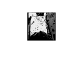
- FIG. 7 is a diagram illustrating an example of a depth map acquired by the estimation processing unit 1321 according to the embodiment of the present disclosure.
- FIG. 8 is a diagram illustrating an example of a ranging area of a depth map by the terminal device 200 according to the embodiment of the present disclosure.
- the estimation processing unit 1321 acquires a depth map as shown in FIG.
- the sensor unit 220 (ranging device) of the terminal device 200 generates the depth map shown in FIG. 7 of the distance to the object existing within the ranging area F0 represented by a quadrangular pyramid in FIG.
- FIG. 9 is a diagram for explaining the reflection of the user U according to the embodiment of the present disclosure.
- the downward angle ⁇ is defined as the angle between the direction vector L of the face of the user U (distance measurement direction of the distance measuring device) and the direction vector G of the center of gravity.
- the distance measuring direction vector L of the distance measuring device is a vector extending perpendicularly from the apex to the bottom of the quadrangular pyramid that is the distance measuring area (see FIG. 8).
- the distance measuring direction vector L is also referred to as the front direction vector L of the distance measuring device or the distance measuring front direction vector L.
- the orientation of the face of the user U and the front direction of distance measurement are the same, but the orientation of the face of the user U and the front direction of distance measurement do not necessarily have to be the same.
- the estimation processing unit 1321 increases the height r of the human region as the downward angle ⁇ decreases.
- 10 and 11 are diagrams for explaining the length r of the human region according to the embodiment of the present disclosure.
- the height r of the human area is defined as the length from the bottom of the depth map. This corresponds to a quadrangular pyramid area F1 having a bottom surface extending from one side to a length r of the bottom surface of the distance measurement area F0 shown as a quadrangular pyramid in FIG.
- the estimation processing unit 1321 determines the length r of the human region using, for example, the following formula (1).
- r max is the maximum value of the length r, and is a value that can be changed according to the size of the depth map, the ranging direction L, and the like.
- ⁇ max and ⁇ min are parameters that are changed according to the value of human region confidence value c, which will be described later.
- the estimation processing unit 1321 can estimate a plurality of human regions having different lengths r according to the human region confidence value c. .
- FIG. 12 and 13 are diagrams for explaining the width w of the human region according to the embodiment of the present disclosure.
- the estimation processing unit 1321 sets a human region F having a human region width w narrower than the width of the depth map, as shown in FIG. This corresponds to a region F2 where the length of the long side of the bottom surface of the region F1 shown as a quadrangular pyramid in FIG. 13 is w.
- the estimation processing unit 1321 changes the width w according to the human region reliability value c, which will be described later. As a result, the estimation processing unit 1321 can estimate a plurality of human regions F with different widths w according to the human region reliability value c.
- the estimation processing unit 1321 estimates a human region F of length r and width w in the depth map, and gives pixels included in the human region F a human region confidence value c.
- the estimation processing unit 1321 estimates a plurality of human regions F.
- the estimation processing unit 1321 sets different human region reliability values c for each of the plurality of human regions F.
- FIG. 14 is a chart showing an example of a human area confidence value table according to the embodiment of the present disclosure.
- the human region confidence value table is generated, for example, based on experiments. It is assumed that the human area reliability value table is stored in advance in the storage unit 120 (see FIG. 6) of the information processing apparatus 100, for example.
- the estimation processing unit 1321 refers to the human region reliability value table stored in the storage unit 120 to determine the human region reliability value c corresponding to the length r and width w.
- the human region confidence value table holds human region confidence values c corresponding to combinations of multiple lengths r and multiple widths w.
- the value of the length r varies depending on the downward angles ⁇ , r max , ⁇ max and ⁇ min .
- the downward angle ⁇ is uniquely determined when the depth map is generated. That is, the rangefinder performs range finding at a predetermined downward angle ⁇ to generate a depth map. Therefore, the length r set for a given depth map is a value corresponding to r max , ⁇ max and ⁇ min . That is, as shown in FIG. 14, multiple lengths r are set according to the values of r max , ⁇ max , and ⁇ min .
- the length r and the width w are values indicating the ratio of the human area F in the height direction or width direction of the depth map. That is, when the length r is "0" or the width w is "0", the depth map does not include the human region F, and when the length r is "1" and the width w is "1", the entire depth map becomes the human area F.
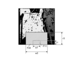
- FIG. 15 and 16 are diagrams for explaining an example of the human area F according to the embodiment of the present disclosure.
- FIG. 15 shows a human area F11 having a length r1 and a width w1, and a human area F33 having a length r3 and a width w3.
- the downward angle ⁇ is assumed to be a predetermined value.
- the estimation processing unit 1321 refers to the human region reliability value table shown in FIG. 14 and sets "1.0" as the human region reliability value c for the pixels included in the human region F11.
- the estimation processing unit 1321 also refers to the human region reliability value table shown in FIG. 14 and sets “0.2” as the human region reliability value c for the pixels included in the human region F33.
- the estimation processing unit 1321 estimates a plurality of human areas F11, F12, F13, F21, F22, F23, F31, F32, and F33 according to the human area reliability value table.
- the estimation processing unit 1321 generates a depth map with a human region confidence value by setting a human region confidence value c for each of a plurality of human regions according to the human region confidence value table.
- the estimation processing unit 1321 outputs the generated depth map with human region confidence value to the integration processing unit 1322 .
- the integration processing unit 1322 generates an occupancy map based on the camera pose and the depth map with human region confidence value.
- the Occupancy Map is a known technique that is generated by the method disclosed, for example, in reference [1].
- the integration processing unit 1322 updates the Occupancy Map each time by changing the occupancy probability based on the depth point observation for each voxel of the Occupancy Map. At this time, the integration processing unit 1322 changes (varies) the occupancy probability according to the value of the human region reliability value c. For example, when changing the occupancy probability, the integration processing unit 1322 reduces the influence of voxels corresponding to pixels with a high human region confidence value c, thereby generating an occupancy map that further reduces false detection of the user U. .
- Z 1:t ) of voxel n is It is calculated based on the following formula (2).
- this formula (2) can be written down as the following formulas (3) and (4).
- the integration processing unit 1322 generates Occupancy Map1 reflecting the human region confidence value c by changing Equation (3) to Equation (5) below.
- c is the human area confidence value. That is, as shown in equation (5), the closer the human region confidence value c is to "1", the less likely it is that the distance information will be reflected in the Occupancy Map.
- the integration processing unit 1322 outputs the generated Occupancy Map to the area estimation unit 133.
- the area estimation unit 133 estimates a play area where the user U can move safely based on the Occupancy Map generated by the integration processing unit 1322, the direction of gravity, the position of the user U, and the like. For example, the area estimation unit 133 estimates the floor plane from the Occupancy Map, and sets the floor plane on which the user U is located as the play area.
- FIG. 17 is a diagram illustrating an example of information processing according to the embodiment of the present disclosure.
- the information processing shown in FIG. 17 is executed, for example, by the information processing apparatus 100 at a predetermined cycle.
- the predetermined period may be the same as the distance measurement period of the distance measuring device.
- the information processing device 100 acquires the position and orientation information and the camera image from the terminal device 200, it executes camera pose estimation processing (step S101) to estimate the camera pose and the direction of gravity.
- the information processing device 100 uses the estimated camera pose and gravity direction, and the distance information acquired from the terminal device 200 to execute the Occupancy Map generation process (step S102) to generate an Occupancy Map.
- FIG. 18 is a diagram showing an example of Occupancy Map generation processing according to the embodiment of the present disclosure.
- the occupancy map generation processing shown in FIG. 18 is executed by the information processing device 100, for example.
- the information processing apparatus 100 performs depth map human region estimation processing using the camera pose, gravity direction, and distance information (depth map) (step S201), and generates a depth map with a human region confidence value.
- the information processing apparatus 100 estimates at least one human region F using the camera pose and the direction of gravity, and sets a human region confidence value c corresponding to the human region F to pixels within the human region F.
- the information processing apparatus 100 sets the human area reliability value c such that the closer the human area is to the distance measuring apparatus, in other words, the user U, the larger the human area reliability value c.
- the information processing device 100 performs depth spatio-temporal integration processing using the camera pose and the depth map with human region confidence value (step S202) to generate an occupancy map. For example, the information processing apparatus 100 updates the occupancy probability of each voxel so that the occupancy probability of voxels corresponding to pixels with a large human region confidence value c is less likely to be updated.
- the information processing apparatus 100 can further reduce erroneous detection of the user U and generate an Occupancy Map with higher accuracy. Therefore, the information processing device 100 can set the play area with higher accuracy.
- Reference [2] discloses a method of detecting a human region from a first-person viewpoint color image using deep learning.
- recognizers used in deep learning require large computational resources.
- reference [2] does not mention the Occupancy Map.
- the information processing apparatus 100 can estimate the human region without using a recognizer, and without using a large computational resource, can quickly determine the location of the user U from the Occupancy Map. The influence can be further reduced.
- the information processing apparatus 100 can generate an occupancy map that reduces the influence of the user U using the sensing results of the distance measuring device and the IMU installed in the terminal device 200. can. In this way, the information processing apparatus 100 can generate a highly accurate Occupancy Map without using a device for detecting the human region F, such as a controller.
- the information processing apparatus 100 can generate an Occupancy Map while the user U is moving. At this time, the information processing apparatus 100 can estimate the area near the moving user U as the human area F, and generate an occupancy map in which the influence of the human area F is reduced.
- the information processing apparatus 100 can generate an occupancy map that reduces the influence of the user U from the gravity direction, camera pose, and depth map. Therefore, when the direction of gravity, camera pose, and depth map can be acquired, the information processing apparatus 100 can generate an occupancy map that reduces the influence of the user U even if a color image cannot be acquired.
- FIG. 19 is a diagram for explaining the posture of the user U according to the first modified example of the embodiment of the present disclosure. As shown in FIG. 19, when the user U is sitting (sitting position), when the user U looks down, the person area F captured by the camera (depth map) becomes larger than when the user U is standing.
- the information processing apparatus 100 detects whether the user U is standing or sitting in addition to the camera pose as the user posture, and corrects the human region F when the sitting position is detected.
- FIG. 20 is a diagram for explaining an example of correction of the human region F according to the first modified example of the embodiment of the present disclosure.
- the information processing apparatus 100 estimates the area having the height r as the human area F as described above.
- the information processing apparatus 100 when the information processing apparatus 100 detects the sitting position of the user U, the information processing apparatus 100 corrects the human area F by calculating the height r using the following formula (6) instead of the formula (1). , to estimate the human region F s .
- FIG. 21 is a diagram showing an example of Occupancy Map generation processing according to the first modification of the embodiment of the present disclosure.
- the control unit 130 (see FIG. 6) of the information processing device 100 executes posture determination processing for determining the posture (standing/sitting) of the user U based on the floor surface and the camera pose (step S301).
- the information processing device 100 detects the floor plane, for example, by calculating the maximum plane with RANSAC for Occupancy Mpa. It should be noted that the calculation of the maximum plane by RANSAC can be performed using, for example, the technique described in reference [3].
- the information processing apparatus 100 detects the eye level of the user U based on the floor plane and the camera pose.
- the information processing apparatus 100 detects the standing position if the detected eye height is equal to or greater than a predetermined threshold, and detects the sitting position if the detected eye height is less than the predetermined threshold.
- the predetermined threshold value may be a value determined in advance, and may be set according to the height of the user U, for example.
- the height of the user U may be input by the user U himself or may be estimated from an external camera (not shown) or the like.
- the information processing apparatus 100 executes depth map human region estimation processing based on the posture of the user U in addition to the camera pose, gravity direction, and distance information (step S302), and generates a depth map with a human region confidence value.
- the information processing apparatus 100 When the information processing apparatus 100 detects a standing position (standing state) as the posture of the user U, the information processing apparatus 100 generates a depth map with a human region confidence value in the same manner as in the embodiment.
- the information processing apparatus 100 uses Equation (6) instead of Equation (1) to generate a depth map with a human region confidence value. do.
- the method for estimating the human region Fs is the same as the method for estimating the human region F in the embodiment except for the calculation of the height rs , so the description is omitted.
- the information processing apparatus 100 can estimate the corrected human area Fs by detecting the sitting position as the posture of the user U, and can further improve the accuracy of generating the Occupancy Map.
- the information processing apparatus 100 detects the ranging front direction as the posture of the user U, but the present invention is not limited to this.
- the information processing device 100 may detect the posture of the user U itself.
- FIG. 22 is a diagram for explaining the posture of the user U according to the second modified example of the embodiment of the present disclosure.
- the information processing device 100 acquires camera images from the terminal device 200 .
- the information processing device 100 estimates the skeleton of the user U as the posture from the camera image.
- a technique for estimating the skeleton as the posture of the user U from a first-person viewpoint camera image is disclosed in Reference [4], for example.
- the information processing apparatus 100 can estimate the posture of the user U using an external sensor, as described in Reference [5], for example.
- FIG. 23 is a diagram for explaining the human region Ft according to the third modification of the embodiment of the present disclosure.
- the information processing apparatus 100 estimates the skeleton of the user U as a posture, and reflects the skeleton in the depth map as shown in the middle diagram of FIG.
- the information processing apparatus 100 defines the human region Ft as a range with a radius rt centered on the skeleton reflected in the depth map.
- the human area reliability value c increases as the value of the radius rt decreases. Also, when human areas with different radii overlap, the information processing apparatus 100 sets the larger value to the human area reliability value c of the overlapping area.
- the information processing apparatus 100 estimates the human region Ft using the skeleton of the user U as the posture of the user U, and generates a depth map with a human region confidence value. Note that the process of generating an occupancy map using a depth map with a human region confidence value is the same as that of the embodiment, and thus description thereof is omitted.
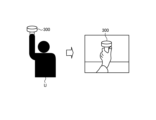
- the information processing apparatus 100 acquires distance information (depth map) including the human arm and the controller 300, as shown in the right diagram of FIG.
- the information processing apparatus 100 also acquires information (for example, position information) on the controller 300 from the controller 300, for example.
- the information processing apparatus 100 estimates the arm of the user U as the human area according to the acquired position information of the controller 300 .
- the information processing device 100 performs clustering processing on the depth map.
- the information processing apparatus 100 performs clustering by calculating the distance between measurement points (pixels) of the depth map using, for example, the k-means method described in Reference [6].
- the information processing device 100 acquires a point group including the controller 300 from among the clustered point groups based on the position information of the controller 300 .
- the information processing apparatus 100 defines a human region F as a point group closer to the terminal device 200 than the controller 300 in the point group including the controller 300 .
- the information processing apparatus 100 generates a depth map with a human region confidence value by setting a human region confidence value c to pixels included in the human region F of the depth map.
- the information processing apparatus 100 performs clustering processing on the depth map shown in the upper left diagram, and detects point cloud areas CL1 and CL2 shown in the lower left diagram. Based on the positional information of the controller 300, the information processing apparatus 100 estimates the point cloud area CL2, which includes the controller 300 and is closer to the terminal device 200 than the controller 300, as the human area F as shown in the right figure.
- FIG. 26 is a diagram showing an example of Occupancy Map generation processing according to the third modification of the embodiment of the present disclosure.
- the information processing device 100 executes depth map human region estimation processing using the camera pose, the direction of gravity, the distance information, and the position information of the controller 300 (step S401).
- the information processing apparatus 100 uses the camera pose, the direction of gravity, and the distance information to estimate the human area F as in the embodiment. Also, the information processing apparatus 100 estimates the arm of the user U as the human area F using the distance information and the position information of the controller 300 .
- the information processing apparatus 100 sets the human region confidence value c to the pixels of the estimated human region F in the depth map, and generates a depth map with human region confidence value. Note that the depth spatio-temporal integration processing using the depth map with the human region confidence value is the same as that of the embodiment, so the description is omitted.
- the information processing apparatus 100 estimates the arm of the user U as the human area F using the position information of the controller 300 held by the user U. As a result, the information processing device 100 can generate an Occupancy Map with higher accuracy.
- the information processing device 100 estimates the point cloud region CL2 closer to the terminal device 200 than the controller 300 as the human region F, but the present invention is not limited to this.
- the information processing apparatus 100 may divide the point cloud region CL2 into a plurality of human regions. More specifically, for example, the information processing apparatus 100 sets a plurality of human regions F in the point cloud region CL2 such that the closer to the terminal device 200, the larger the human region reliability value c. may
- the information processing apparatus 100 updates the voxels of the Occupancy Map with the degree of influence according to the value of the human region reliability value c, but the present invention is not limited to this.
- the information processing apparatus 100 generates an occupancy map using the human area reliability value c will be described.
- the information processing apparatus 100 generates two human area Occupancy Maps (human area environment information) and an environment Occupancy Map (surrounding environment information), and from the human area Occupancy Map and the environment Occupancy Map, the user U Generate an Occupancy Map with reduced impact.
- the human area occupancy map is an occupancy map in which the human area confidence value c is input as the occupancy probability.
- the environment occupancy map is an occupancy map generated without using the human area confidence value c, and corresponds to the conventional occupancy map.
- FIG. 27 is a diagram showing an example of an environment Occupancy Map according to the fourth modification of the embodiment of the present disclosure.
- the information processing device 100 generates an environment Occupancy Map, for example, based on the distance information acquired by the ranging device of the terminal device 200 . That is, the information processing device 100 generates the environment Occupancy Map without using the human region confidence value c. Therefore, the environment Occupancy Map includes the user U as an object (obstacle), as indicated by the circled portion in FIG.
- FIG. 28 is a diagram showing an example of a human area Occupancy Map according to the fourth modification of the embodiment of the present disclosure.
- the information processing apparatus 100 sets the occupancy probability of the voxel corresponding to the pixel for which the human region reliability value c is set as the set human region reliability value c, for example, based on the depth map with the human region reliability value. That is, the information processing device 100 uses the human region confidence value c as the object occupancy probability to generate the human region occupancy map.
- the Human Area Occupancy Map treats whether or not it is a human area as an occupancy probability. Therefore, the human area Occupancy Map becomes an Occupancy Map corresponding to the human area.
- the information processing device 100 generates an Occupancy Map that does not include the human area by subtracting the human area Occupancy Map from the generated environment Occupancy Map. More specifically, the information processing apparatus 100 generates the Occupancy Map by regarding the voxels of the environment Occupancy Map corresponding to the Occupied voxels of the human region Occupancy Map as Unknown voxels.
- FIG. 29 is a diagram showing an example of an Occupancy Map according to the fourth modification of the embodiment of the present disclosure.
- the information processing apparatus 100 generates an occupancy map that does not include the human area by subtracting the human area occupancy map from the generated environment occupancy map.
- FIG. 30 is a diagram showing an example of Occupancy Map generation processing according to the fourth modification of the embodiment of the present disclosure. Note that the processing of the information processing apparatus 100 for generating a depth map with a human region confidence value is the same as that of the embodiment, and thus the description thereof is omitted.
- the information processing device 100 executes the first Occupancy Map generation process using the camera pose and the depth map with the human region confidence value (step S501) to generate the human region Occupancy Map. For example, the information processing device 100 generates a human area occupancy map using the human area confidence value c as the object occupancy probability.
- the information processing device 100 also uses the camera pose and distance information (depth map) to execute the second Occupancy Map generation process (step S502) to generate an environment Occupancy Map.
- the human region confidence value c is not assigned to the distance information (depth map) used by the information processing apparatus 100 to generate the environment Occupanry Map.
- the information processing device 100 generates an environment Occupancy Map using, for example, an existing method.
- the information processing device 100 executes map integration processing using the generated human region occupancy map and environment occupancy map (step S503) to generate an occupancy map.
- the information processing device 100 generates an occupancy map that does not include the human area by subtracting (or masking) the human area occupancy map from the environment occupancy map.
- the information processing device 100 generates the human region occupancy map, and subtracts the human region occupancy map from the environment occupancy map to generate an occupancy map that further reduces the influence of the user U. be able to.
- the information processing apparatus 100 can generate an occupancy map in which the influence of human regions is further reduced by using plane information.
- generation of an occupancy map using plane information, which is a plane area, will be described as a fifth modification.
- the user U's surrounding environment includes many planes parallel to the floor, such as desks.
- the plane does not include the human area. Therefore, the information processing apparatus 100 generates an occupancy map by excluding the plane area from the human area.
- FIG. 31 is a diagram for explaining a plane region according to the fifth modified example of the embodiment of the present disclosure.
- the information processing apparatus 100 estimates a rectangular human region F having a height r and a width w. Therefore, as shown in FIG. 31, not only the user U but also a planar area P such as the floor may be included.
- the information processing apparatus 100 corrects the human area F by excluding the plane area P from the human area F, and generates an occupancy map.
- FIG. 32 is a diagram showing an example of a plane detection map according to the fifth modification of the embodiment of the present disclosure.
- the information processing device 100 detects a plane from the plane detection map. For example, the information processing apparatus 100 acquires a set of central points of voxels as a point cloud for each occupied voxel of the plane detection map. Next, the information processing apparatus 100 detects iterative planes using RANSAC described in Reference [3], for example.
- the information processing apparatus 100 extracts, from among the detected planes, planes that have normals in the direction of gravity and that include points equal to or larger than a predetermined threshold as plane regions. For example, in FIG. 32, the information processing apparatus 100 extracts two plane regions P1 and P2. In this manner, the information processing apparatus 100 may extract one or a plurality of plane regions.
- the information processing device 100 updates the Occupancy Map using the depth map with the human region confidence value. At this time, the information processing apparatus 100 updates the Occupancy Map by regarding the human region reliability value c of the voxels included in the detected plane region as "0".
- FIG. 33 is a diagram showing an example of Occupancy Map generation processing according to the fifth modification of the embodiment of the present disclosure. It should be noted that the depth map human region estimation processing shown in FIG. 33 is the same as the processing of the embodiment, and thus the description thereof is omitted.
- the information processing apparatus 100 executes plane estimation processing using the camera pose, the gravity direction, and the distance information (step S601), and extracts a plane area.
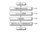
- FIG. 34 is a flowchart showing an example of the flow of plane estimation processing according to the fifth modification of the embodiment of the present disclosure.
- the information processing apparatus 100 generates a plane detection map (step S701). For example, the information processing apparatus 100 generates a plane detection map by updating the occupancy map without using the human region confidence value c.
- the information processing apparatus 100 acquires a point cloud from the plane detection map (step S702). For example, the information processing apparatus 100 acquires a set of central points of voxels as a point cloud for each occupied voxel of the plane detection map.
- the information processing apparatus 100 detects a plane using the acquired pint cloud (step S703).
- the information processing apparatus 100 repeatedly detects planes using RANSAC described in Reference [3], for example.
- the information processing apparatus 100 extracts a plane area according to the normal direction from the plane detected in step S703 (step S704).
- the information processing apparatus 100 extracts, from among the detected planes, planes that have normals in the direction of gravity and that include points equal to or larger than a predetermined threshold as plane regions parallel to the floor.
- the information processing device 100 that has extracted the plane region in the plane estimation process executes depth spatio-temporal integration processing using the plane region, the camera pose, and the depth map with the human region confidence value (step S602), and obtains the Occupancy Map. Generate.
- the information processing apparatus 100 updates the Occupancy Map by regarding the human area reliability value c of the voxels included in the plane area as "0".
- the information processing apparatus 100 detects a planar area parallel to the floor, excludes the planar area from the human area, and generates an occupancy map. Accordingly, even when the human region of the depth map includes the environment such as the floor and the table near the user U, the information processing apparatus 100 can estimate the human region more accurately. Therefore, the information processing device 100 can generate a more accurate Occupancy Map.
- the terminal device 200 may implement a part of the functions of the information processing device 100 of this embodiment.
- the terminal device 200 may generate a depth map with a human region confidence value, or may generate an Occupancy Map.
- the information processing device 100 sets the user U's play area, but the present invention is not limited to this.
- the information processing apparatus 100 may set a range in which moving objects such as vehicles and drones can safely move as the play area.
- the information processing apparatus 100 may set, as the play area, a range in which a partially fixed object such as a robot arm can be safely driven.
- the target object for which the information processing apparatus 100 sets the play area is not limited to the user U.
- a communication program for executing the above operations is distributed by storing it in a computer-readable recording medium such as an optical disk, semiconductor memory, magnetic tape, or flexible disk.
- the control device is configured by installing the program in a computer and executing the above-described processing.
- the control device may be a device (for example, a personal computer) external to the information processing device 100 and the terminal device 200 .
- the control device may be a device inside the information processing device 100 and the terminal device 200 (for example, the control units 130 and 250).
- the above communication program may be stored in a disk device provided in a server device on a network such as the Internet, so that it can be downloaded to a computer.
- the functions described above may be realized through cooperation between an OS (Operating System) and application software.
- the parts other than the OS may be stored in a medium and distributed, or the parts other than the OS may be stored in a server device so that they can be downloaded to a computer.
- each component of each device illustrated is functionally conceptual and does not necessarily need to be physically configured as illustrated.
- the specific form of distribution and integration of each device is not limited to the illustrated one, and all or part of them can be functionally or physically distributed and integrated in arbitrary units according to various loads and usage conditions. Can be integrated and configured. Note that this distribution/integration configuration may be performed dynamically.
- the present embodiment can be applied to any configuration that constitutes a device or system, such as a processor as a system LSI (Large Scale Integration), a module using a plurality of processors, a unit using a plurality of modules, etc. Furthermore, it can also be implemented as a set or the like (that is, a configuration of a part of the device) to which other functions are added.
- a processor as a system LSI (Large Scale Integration)
- module using a plurality of processors a unit using a plurality of modules, etc.
- it can also be implemented as a set or the like (that is, a configuration of a part of the device) to which other functions are added.
- the system means a set of a plurality of components (devices, modules (parts), etc.), and it does not matter whether all the components are in the same housing. Therefore, a plurality of devices housed in separate housings and connected via a network, and a single device housing a plurality of modules in one housing, are both systems. .
- this embodiment can take a configuration of cloud computing in which one function is shared by a plurality of devices via a network and processed jointly.
- FIG. 35 is a hardware configuration diagram showing an example of a computer 1000 that implements the functions of the information processing apparatus 100 according to the embodiment of the present disclosure.
- the computer 1000 has a CPU 1100 , a RAM 1200 , a ROM (Read Only Memory) 1300 , a HDD (Hard Disk Drive) 1400 , a communication interface 1500 and an input/output interface 1600 .
- Each part of computer 1000 is connected by bus 1050 .
- the CPU 1100 operates based on programs stored in the ROM 1300 or HDD 1400 and controls each section. For example, the CPU 1100 loads programs stored in the ROM 1300 or HDD 1400 into the RAM 1200 and executes processes corresponding to various programs.
- the ROM 1300 stores boot programs such as BIOS (Basic Input Output System) executed by the CPU 1100 when the computer 1000 is started, and programs dependent on the hardware of the computer 1000.
- BIOS Basic Input Output System
- the HDD 1400 is a computer-readable recording medium that non-temporarily records programs executed by the CPU 1100 and data used by such programs.
- HDD 1400 is a recording medium that records a program for the medical arm control method according to the present disclosure, which is an example of program data 1450 .
- a communication interface 1500 is an interface for connecting the computer 1000 to an external network 1550 (for example, the Internet).
- CPU 1100 receives data from another device via communication interface 1500, and transmits data generated by CPU 1100 to another device.
- the input/output interface 1600 is an interface for connecting the input/output device 1650 and the computer 1000 .
- the CPU 1100 receives data from input devices such as a keyboard and mouse via the input/output interface 1600 .
- the CPU 1100 also transmits data to an output device such as a display, speaker, or printer via the input/output interface 1600 .
- the input/output interface 1600 may function as a media interface for reading a program or the like recorded on a predetermined computer-readable recording medium.
- Media include, for example, optical recording media such as DVD (Digital Versatile Disc) and PD (Phase change rewritable disk), magneto-optical recording media such as MO (Magneto-Optical disk), tape media, magnetic recording media, semiconductor memories, etc. is.
- the CPU 1100 of the computer 1000 implements the functions of the control unit 130 and the like by executing programs loaded on the RAM 1200.
- CPU 1100 reads program data 1450 from HDD 1400 and executes it, as another example, an information processing program may be obtained from another device via external network 1550 .
- the information processing apparatus 100 may be applied to a system composed of a plurality of devices on the premise of connection to a network (or communication between devices), such as cloud computing. good. That is, the information processing apparatus 100 according to the present embodiment described above can be realized as the information processing system 1 according to the present embodiment by, for example, a plurality of apparatuses.
- Each component described above may be configured using general-purpose members, or may be configured by hardware specialized for the function of each component. Such a configuration can be changed as appropriate according to the technical level of implementation.
- the present technology can also take the following configuration.
- a human region including the user is estimated from distance information generated based on a distance measuring device mounted on the device.
- a control unit that updates environment information around the user based on the person area and the distance information;
- the distance information is a depth map;
- the control unit assigns a human region confidence value to the pixel of the depth map when the pixel is included in the human region.
- the environment information is an occupancy grid map;
- the control unit updates the occupancy state of each grid of the occupancy grid map with a value corresponding to the human region confidence value.
- the information processing device estimates the user's arm as the person region according to the position of the second device held by the user.
- the control unit (1) updating the environment information using human area environment information generated based on the distance information in the human area and surrounding environment information generated based on the distance information in all areas;
- the information processing device according to .
- the environment information, the human area environment information, and the surrounding environment information are occupancy grid maps;
- the control unit The information processing apparatus according to any one of (1) to (10), wherein the human region is corrected based on plane information detected using the distance information.
- the information processing device according to any one of (1) to (11), wherein the device used by the user is a device that is worn on the head of the user and provides predetermined content to the user.
- a human region including the user is estimated from distance information generated based on a distance measuring device mounted on the device. and updating environment information around the user based on the person area and the distance information; Information processing method including.
- a human region including the user is estimated from distance information generated based on a distance measuring device mounted on the device.
- a control unit that updates environment information around the user based on the person area and the distance information;
- information processing system 100 information processing device 110, 210 communication unit 120 storage unit 130, 250 control unit 200 terminal device 220 sensor unit 230 display unit 230 display unit 240 input unit 300 controller
Landscapes
- Engineering & Computer Science (AREA)
- Multimedia (AREA)
- Theoretical Computer Science (AREA)
- General Physics & Mathematics (AREA)
- Physics & Mathematics (AREA)
- Human Computer Interaction (AREA)
- General Engineering & Computer Science (AREA)
- Computer Vision & Pattern Recognition (AREA)
- General Business, Economics & Management (AREA)
- General Health & Medical Sciences (AREA)
- Heart & Thoracic Surgery (AREA)
- Cardiology (AREA)
- Biophysics (AREA)
- Life Sciences & Earth Sciences (AREA)
- Health & Medical Sciences (AREA)
- Computer Security & Cryptography (AREA)
- Business, Economics & Management (AREA)
- Image Analysis (AREA)
Priority Applications (4)
| Application Number | Priority Date | Filing Date | Title |
|---|---|---|---|
| EP22863911.8A EP4397943A4 (en) | 2021-08-31 | 2022-03-23 | INFORMATION PROCESSING DEVICE, INFORMATION PROCESSING METHOD AND PROGRAM |
| CN202280057128.4A CN117859039A (zh) | 2021-08-31 | 2022-03-23 | 信息处理装置、信息处理方法和程序 |
| US18/684,045 US20240386693A1 (en) | 2021-08-31 | 2022-03-23 | Information processing apparatus, information processing method, and program |
| JP2023545063A JPWO2023032321A1 (https=) | 2021-08-31 | 2022-03-23 |
Applications Claiming Priority (2)
| Application Number | Priority Date | Filing Date | Title |
|---|---|---|---|
| JP2021141542 | 2021-08-31 | ||
| JP2021-141542 | 2021-08-31 |
Publications (1)
| Publication Number | Publication Date |
|---|---|
| WO2023032321A1 true WO2023032321A1 (ja) | 2023-03-09 |
Family
ID=85411675
Family Applications (1)
| Application Number | Title | Priority Date | Filing Date |
|---|---|---|---|
| PCT/JP2022/013402 Ceased WO2023032321A1 (ja) | 2021-08-31 | 2022-03-23 | 情報処理装置、情報処理方法及びプログラム |
Country Status (5)
| Country | Link |
|---|---|
| US (1) | US20240386693A1 (https=) |
| EP (1) | EP4397943A4 (https=) |
| JP (1) | JPWO2023032321A1 (https=) |
| CN (1) | CN117859039A (https=) |
| WO (1) | WO2023032321A1 (https=) |
Families Citing this family (2)
| Publication number | Priority date | Publication date | Assignee | Title |
|---|---|---|---|---|
| WO2022202056A1 (ja) * | 2021-03-22 | 2022-09-29 | ソニーグループ株式会社 | 情報処理装置、情報処理方法、およびプログラム |
| KR20260046705A (ko) * | 2024-09-30 | 2026-04-07 | 한국전자통신연구원 | 무인 항공기의 탐색 경로를 계획하기 위한 전자 장치 및 전자 장치의 동작 방법 |
Citations (2)
| Publication number | Priority date | Publication date | Assignee | Title |
|---|---|---|---|---|
| WO2018173399A1 (ja) * | 2017-03-21 | 2018-09-27 | ソニー株式会社 | 情報処理装置、情報処理方法、およびプログラム |
| WO2020203831A1 (ja) * | 2019-03-29 | 2020-10-08 | 株式会社ソニー・インタラクティブエンタテインメント | 境界設定装置、境界設定方法及びプログラム |
Family Cites Families (8)
| Publication number | Priority date | Publication date | Assignee | Title |
|---|---|---|---|---|
| US9571816B2 (en) * | 2012-11-16 | 2017-02-14 | Microsoft Technology Licensing, Llc | Associating an object with a subject |
| US12235659B2 (en) * | 2016-02-29 | 2025-02-25 | AI Incorporated | Obstacle recognition method for autonomous robots |
| US11927965B2 (en) * | 2016-02-29 | 2024-03-12 | AI Incorporated | Obstacle recognition method for autonomous robots |
| US9996944B2 (en) * | 2016-07-06 | 2018-06-12 | Qualcomm Incorporated | Systems and methods for mapping an environment |
| US10803663B2 (en) * | 2017-08-02 | 2020-10-13 | Google Llc | Depth sensor aided estimation of virtual reality environment boundaries |
| US11178373B2 (en) * | 2018-07-31 | 2021-11-16 | Intel Corporation | Adaptive resolution of point cloud and viewpoint prediction for video streaming in computing environments |
| US11099638B2 (en) * | 2019-10-24 | 2021-08-24 | Facebook Technologies, Llc | Systems and methods for generating dynamic obstacle collision warnings based on detecting poses of users |
| US11507203B1 (en) * | 2021-06-21 | 2022-11-22 | Meta Platforms Technologies, Llc | Body pose estimation using self-tracked controllers |
-
2022
- 2022-03-23 JP JP2023545063A patent/JPWO2023032321A1/ja active Pending
- 2022-03-23 US US18/684,045 patent/US20240386693A1/en active Pending
- 2022-03-23 EP EP22863911.8A patent/EP4397943A4/en active Pending
- 2022-03-23 WO PCT/JP2022/013402 patent/WO2023032321A1/ja not_active Ceased
- 2022-03-23 CN CN202280057128.4A patent/CN117859039A/zh active Pending
Patent Citations (2)
| Publication number | Priority date | Publication date | Assignee | Title |
|---|---|---|---|---|
| WO2018173399A1 (ja) * | 2017-03-21 | 2018-09-27 | ソニー株式会社 | 情報処理装置、情報処理方法、およびプログラム |
| WO2020203831A1 (ja) * | 2019-03-29 | 2020-10-08 | 株式会社ソニー・インタラクティブエンタテインメント | 境界設定装置、境界設定方法及びプログラム |
Non-Patent Citations (5)
| Title |
|---|
| ANDRIJA GAJIC ET AL.: "Egocentric Human Segmentation for Mixed Reality", ARXIV, 2020 |
| ARMIN HORNUNG ET AL.: "OctoMap: An efficient probabilistic 3D mapping framework based on octrees.", AUTONOMOUS ROBOTS, vol. 34, no. 3, 2013, pages 189 - 206, XP055147395, DOI: 10.1007/s10514-012-9321-0 |
| BUGRA TEKIN ET AL., STRUCTURED PREDICTION OF 3D HUMAN POSE WITH DEEP NEURAL NETWORKS |
| DENIS TOME ET AL.: "xR-EgoPose: Egocentric 3D Human Pose from an HMD Camera", INTERNATIONAL CONFERENCE ON COMPUTER VISION (ICCV, 2019 |
| RUWEN SCHNABEL ET AL.: "Computer graphics forum.", vol. 26, 2007, BLACKWELL PUBLISHING LTD, article "Efficient RANSAC for point-cloud shape detection." |
Also Published As
| Publication number | Publication date |
|---|---|
| CN117859039A (zh) | 2024-04-09 |
| EP4397943A4 (en) | 2024-12-18 |
| EP4397943A1 (en) | 2024-07-10 |
| JPWO2023032321A1 (https=) | 2023-03-09 |
| US20240386693A1 (en) | 2024-11-21 |
Similar Documents
| Publication | Publication Date | Title |
|---|---|---|
| CN111344644B (zh) | 用于基于运动的自动图像捕获的技术 | |
| EP3956867B1 (en) | 2d obstacle boundary detection | |
| EP3271687B1 (en) | Augmented reality navigation | |
| JP7420135B2 (ja) | 情報処理装置、情報処理方法、及びプログラム | |
| JP7782933B2 (ja) | 拡張現実提供装置のポーズ決定方法及び装置 | |
| JP2022529367A (ja) | 姿勢付き単眼ビデオからの周囲推定 | |
| US10992916B2 (en) | Depth data adjustment based on non-visual pose data | |
| WO2018174954A1 (en) | System and method for merging maps | |
| CN113228117B (zh) | 创作装置、创作方法和记录有创作程序的记录介质 | |
| US20240362860A1 (en) | Calculation method and calculation device | |
| WO2023032321A1 (ja) | 情報処理装置、情報処理方法及びプログラム | |
| JP7103354B2 (ja) | 情報処理装置、情報処理方法、及びプログラム | |
| EP4435721A1 (en) | Information processing device, information processing method, and program | |
| US20250191301A1 (en) | Information processing apparatus, information processing method, and program | |
| CN114332448B (zh) | 基于稀疏点云的平面拓展方法及其系统和电子设备 | |
| JP6385621B2 (ja) | 画像表示装置、画像表示方法及び画像表示プログラム | |
| US12306403B2 (en) | Electronic device and method for controlling electronic device | |
| JP7701101B2 (ja) | 地図生成装置、地図生成方法、及びプログラム | |
| US20250180360A1 (en) | Information processing apparatus, method, and storage medium | |
| US20250218113A1 (en) | System and method with 3d layout model generator | |
| KR20230161309A (ko) | 깊이 정보를 획득하는 증강 현실 디바이스 및 그 동작 방법 | |
| CN120129931A (zh) | 信息处理装置、信息处理方法和程序 | |
| CN121752870A (zh) | 特征关联 | |
| JP2020095671A (ja) | 認識装置及び認識方法 |
Legal Events
| Date | Code | Title | Description |
|---|---|---|---|
| 121 | Ep: the epo has been informed by wipo that ep was designated in this application |
Ref document number: 22863911 Country of ref document: EP Kind code of ref document: A1 |
|
| WWE | Wipo information: entry into national phase |
Ref document number: 2023545063 Country of ref document: JP |
|
| WWE | Wipo information: entry into national phase |
Ref document number: 18684045 Country of ref document: US |
|
| WWE | Wipo information: entry into national phase |
Ref document number: 202280057128.4 Country of ref document: CN |
|
| WWE | Wipo information: entry into national phase |
Ref document number: 2022863911 Country of ref document: EP |
|
| NENP | Non-entry into the national phase |
Ref country code: DE |
|
| ENP | Entry into the national phase |
Ref document number: 2022863911 Country of ref document: EP Effective date: 20240402 |