WO2023032091A1 - 検出システム、検出装置、及び検出方法 - Google Patents
検出システム、検出装置、及び検出方法 Download PDFInfo
- Publication number
- WO2023032091A1 WO2023032091A1 PCT/JP2021/032160 JP2021032160W WO2023032091A1 WO 2023032091 A1 WO2023032091 A1 WO 2023032091A1 JP 2021032160 W JP2021032160 W JP 2021032160W WO 2023032091 A1 WO2023032091 A1 WO 2023032091A1
- Authority
- WO
- WIPO (PCT)
- Prior art keywords
- optical fiber
- fiber cable
- sensing data
- abnormality
- sensing
- Prior art date
- Legal status (The legal status is an assumption and is not a legal conclusion. Google has not performed a legal analysis and makes no representation as to the accuracy of the status listed.)
- Ceased
Links
Images


Classifications
-
- G—PHYSICS
- G01—MEASURING; TESTING
- G01H—MEASUREMENT OF MECHANICAL VIBRATIONS OR ULTRASONIC, SONIC OR INFRASONIC WAVES
- G01H9/00—Measuring mechanical vibrations or ultrasonic, sonic or infrasonic waves by using radiation-sensitive means, e.g. optical means
- G01H9/004—Measuring mechanical vibrations or ultrasonic, sonic or infrasonic waves by using radiation-sensitive means, e.g. optical means using fibre optic sensors
-
- G—PHYSICS
- G01—MEASURING; TESTING
- G01D—MEASURING NOT SPECIALLY ADAPTED FOR A SPECIFIC VARIABLE; ARRANGEMENTS FOR MEASURING TWO OR MORE VARIABLES NOT COVERED IN A SINGLE OTHER SUBCLASS; TARIFF METERING APPARATUS; MEASURING OR TESTING NOT OTHERWISE PROVIDED FOR
- G01D5/00—Mechanical means for transferring the output of a sensing member; Means for converting the output of a sensing member to another variable where the form or nature of the sensing member does not constrain the means for converting; Transducers not specially adapted for a specific variable
- G01D5/26—Mechanical means for transferring the output of a sensing member; Means for converting the output of a sensing member to another variable where the form or nature of the sensing member does not constrain the means for converting; Transducers not specially adapted for a specific variable characterised by optical transfer means, i.e. using infrared, visible, or ultraviolet light
- G01D5/32—Mechanical means for transferring the output of a sensing member; Means for converting the output of a sensing member to another variable where the form or nature of the sensing member does not constrain the means for converting; Transducers not specially adapted for a specific variable characterised by optical transfer means, i.e. using infrared, visible, or ultraviolet light with attenuation or whole or partial obturation of beams of light
- G01D5/34—Mechanical means for transferring the output of a sensing member; Means for converting the output of a sensing member to another variable where the form or nature of the sensing member does not constrain the means for converting; Transducers not specially adapted for a specific variable characterised by optical transfer means, i.e. using infrared, visible, or ultraviolet light with attenuation or whole or partial obturation of beams of light the beams of light being detected by photocells
- G01D5/353—Mechanical means for transferring the output of a sensing member; Means for converting the output of a sensing member to another variable where the form or nature of the sensing member does not constrain the means for converting; Transducers not specially adapted for a specific variable characterised by optical transfer means, i.e. using infrared, visible, or ultraviolet light with attenuation or whole or partial obturation of beams of light the beams of light being detected by photocells influencing the transmission properties of an optical fibre
- G01D5/35338—Mechanical means for transferring the output of a sensing member; Means for converting the output of a sensing member to another variable where the form or nature of the sensing member does not constrain the means for converting; Transducers not specially adapted for a specific variable characterised by optical transfer means, i.e. using infrared, visible, or ultraviolet light with attenuation or whole or partial obturation of beams of light the beams of light being detected by photocells influencing the transmission properties of an optical fibre using other arrangements than interferometer arrangements
- G01D5/35354—Sensor working in reflection
- G01D5/35358—Sensor working in reflection using backscattering to detect the measured quantity
- G01D5/35361—Sensor working in reflection using backscattering to detect the measured quantity using elastic backscattering to detect the measured quantity, e.g. using Rayleigh backscattering
Definitions
- the present disclosure relates to detection systems, detection devices, and detection methods.
- optical fiber sensing which uses optical fibers as sensors for sensing.
- optical fiber sensing is interferometric optical fiber sensing.
- the reflected light received from the sensing fiber and the reflected light received from the reference fiber interfere with each other. Techniques are disclosed.
- Patent Literature 2 discloses a technique of detecting the environment around an optical fiber cable (for example, the state of a structure such as a utility pole) by performing distributed optical fiber sensing.
- DFOS Distributed Fiber Optic Sensing
- DVS Distributed Vibration Sensing
- Patent Document 2 detects the environment around the optical fiber cable by performing distributed optical fiber sensing.
- the optical fiber cable itself has an abnormality (for example, damage caused by animal feeding).
- an abnormality for example, damage caused by animal feeding.
- the detection results also fluctuate.
- an object of the present disclosure is to solve the above-described problems and to provide a detection system, a detection device, and a detection method that can detect that an abnormality has occurred in the optical fiber cable itself.
- a detection system comprises: a first optical fiber cable and a second optical fiber cable; By performing optical fiber sensing using each of the first optical fiber cable and the second optical fiber cable, first sensing data corresponding to the first optical fiber cable is acquired, and the second light is obtained. a sensing unit that acquires second sensing data corresponding to the fiber cable; an abnormality detection unit that detects occurrence of an abnormality in the first optical fiber cable or the second optical fiber cable based on both the first sensing data and the second sensing data; Prepare.
- a detection device comprises: Acquiring first sensing data corresponding to the first optical fiber cable from a sensing unit that performs optical fiber sensing using each of the first optical fiber cable and the second optical fiber cable, and obtaining the first sensing data corresponding to the first optical fiber cable and the second optical fiber an acquisition unit that acquires second sensing data corresponding to the cable; an abnormality detection unit that detects occurrence of an abnormality in the first optical fiber cable or the second optical fiber cable based on both the first sensing data and the second sensing data; Prepare.
- a detection method comprises: A detection method using a detection device, Acquiring first sensing data corresponding to the first optical fiber cable from a sensing unit that performs optical fiber sensing using each of the first optical fiber cable and the second optical fiber cable, and obtaining the first sensing data corresponding to the first optical fiber cable and the second optical fiber an acquiring step of acquiring second sensing data corresponding to the cable; an abnormality detection step of detecting occurrence of an abnormality in the first optical fiber cable or the second optical fiber cable based on both the first sensing data and the second sensing data; including.
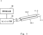
- FIG. 1 is a diagram showing a configuration example of a detection system according to Embodiment 1;
- FIG. FIG. 4 is a diagram showing a modified configuration example of the detection system according to Embodiment 1;
- FIG. 5 is a flow diagram illustrating an example of a schematic operation flow when detecting occurrence of abnormality in the first optical fiber cable or the second optical fiber cable in the detection system according to Embodiment 1;
- FIG. 10 is a diagram showing a configuration example of a detection system according to Embodiment 2; An example in which the difference value between the vibration intensity indicated by the first sensing data and the vibration intensity indicated by the second sensing data fluctuates when an abnormality occurs in either the first optical fiber cable or the second optical fiber cable will be described. It is a diagram.
- FIG. 1 is a diagram showing a configuration example of a detection system according to Embodiment 1
- FIG. FIG. 4 is a diagram showing a modified configuration example of the detection system according to Embodiment 1
- FIG. 5 is a
- FIG. 10 is a flow diagram illustrating an example of a schematic operation flow when detecting occurrence of abnormality in the first optical fiber cable or the second optical fiber cable in the detection system according to the second embodiment; It is a figure which shows the example of the correspondence table which the abnormality detection part which concerns on other embodiment uses. It is a block diagram showing a hardware configuration example of a computer that realizes a detection device according to each embodiment.
- the detection system 1 according to the first embodiment includes a first optical fiber cable 10-1, a second optical fiber cable 10-2, a sensing unit 20, and an abnormality detection unit 30.
- a first optical fiber cable 10-1 includes a first optical fiber cable 10-1, a second optical fiber cable 10-2, a sensing unit 20, and an abnormality detection unit 30.
- the first optical fiber cable 10-1 includes at least one first optical fiber 11-1. Also, the second optical fiber cable 10-2 includes at least one second optical fiber 11-2.
- the first optical fiber cable 10-1 and the second optical fiber cable 10-2 are arranged so as to extend substantially parallel to each other. Also, the first optical fiber cable 10-1 and the second optical fiber cable 10-2 are arranged adjacent to each other. For example, the first optical fiber cable 10-1 and the second optical fiber cable 10-2 may be arranged in close contact with each other, or may be arranged at a predetermined interval.
- optical fiber cables consisting of the first optical fiber cable 10-1 and the second optical fiber cable 10-2 are provided in FIG. 1, the number of optical fiber cables is limited to two. It may be three or more.
- the sensing unit 20 performs optical fiber sensing using each of the first optical fiber cable 10-1 and the second optical fiber cable 10-2. For example, the sensing unit 20 performs distributed fiber optic sensing. Thereby, the sensing unit 20 acquires the first sensing data indicating the detection result detected by the first optical fiber cable 10-1 (for example, vibration generated around the first optical fiber cable 10-1), Second sensing data indicating the detection result detected by the second optical fiber cable 10-2 (for example, vibration generated around the second optical fiber cable 10-2) is acquired.
- the abnormality detection unit 30 detects the occurrence of an abnormality in the first optical fiber cable 10-1 or the second optical fiber cable 10-2 based on both the first sensing data and the second sensing data acquired by the sensing unit 20. To detect.
- the abnormality detection unit 30 may be provided in the same device as the sensing unit 20, may be provided in a device different from the sensing unit 20, or may be provided on the cloud.
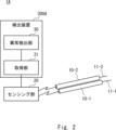
- FIG. 2 shows a configuration example of a detection system 1A in which the abnormality detection unit 30 is provided in a device (detection device 300A) different from the sensing unit 20. As shown in FIG. In the detection system 1A shown in FIG. 2, an acquisition unit 31 that acquires the first sensing data and the second sensing data from the sensing unit 20 is added to the detection device 300A.
- FIG. 3 in the detection system 1 according to the first embodiment, a schematic diagram of detecting occurrence of an abnormality in the first optical fiber cable 10-1 or the second optical fiber cable 10-2 is shown. An example of the flow of operations will be described.
- the sensing unit 20 performs optical fiber sensing using each of the first optical fiber cable 10-1 and the second optical fiber cable 10-2. As a result, the sensing unit 20 acquires first sensing data corresponding to the first optical fiber cable 10-1 and acquires second sensing data corresponding to the second optical fiber cable 10-2 (step S101). .
- the abnormality detection unit 30 detects an abnormality in the first optical fiber cable 10-1 or the second optical fiber cable 10-2. The occurrence is detected (step S102).
- the sensing unit 20 uses each of the first optical fiber cable 10-1 and the second optical fiber cable 10-2 to execute optical fiber sensing, First sensing data corresponding to the first optical fiber cable 10-1 is acquired, and second sensing data corresponding to the second optical fiber cable 10-2 is acquired.
- the abnormality detection unit 30 detects the occurrence of abnormality in the first optical fiber cable 10-1 or the second optical fiber cable 10-2 based on both the first sensing data and the second sensing data. This makes it possible to detect that an abnormality has occurred in the first optical fiber cable 10-1 or the second optical fiber cable 10-2 itself.
- the second embodiment is a specific embodiment of the first embodiment described above, and is an example of detecting the running condition of a vehicle around the optical fiber cable as the environment around the optical fiber cable.
- the detection system 1B according to Embodiment 2 includes a first optical fiber cable 100-1, a second optical fiber cable 100-2, a sensing device 200, and a detection device 300B.
- FIG. 4 shows a state in which an abnormality (here, human injury using a knife) occurs in the first optical fiber cable 100-1.
- the first optical fiber cable 100-1 and the second optical fiber cable 100-2 correspond to the first optical fiber cable 10-1 and the second optical fiber cable 10-2 in Embodiment 1 described above.
- the term "optical fiber cable 100" is appropriately used.
- the sensing device 200 corresponds to the sensing unit 20 in the first embodiment described above.
- An abnormality detection unit 303 and an acquisition unit 301, which will be described later, in the detection device 300B correspond to the abnormality detection unit 30 and the acquisition unit 31 in Embodiment 1 described above, respectively.
- the first optical fiber cable 100-1 includes at least one first optical fiber 101-1. Also, the second optical fiber cable 100-2 includes at least one second optical fiber 101-2.
- the first optical fiber cable 100-1 and the second optical fiber cable 100-2 are arranged to extend substantially parallel to each other along a road (not shown).
- the first optical fiber cable 100-1 and the second optical fiber cable 100-2 are arranged inside the truss 103 installed along the road, but this arrangement method is limited. It should be placed along the road instead.
- first optical fiber cable 100-1 and the second optical fiber cable 100-2 are arranged adjacent to each other.
- first optical fiber cable 100-1 and the second optical fiber cable 100-2 may be arranged in close contact with each other, or may be arranged at a predetermined interval.
- the number of the optical fiber cables 100 is reduced to two.
- the number is not limited, and may be three or more.
- the sensing device 200 performs distributed optical fiber sensing using each of the first optical fiber cable 100-1 and the second optical fiber cable 100-2, and includes a first DFOS unit 201 and a second DFOS unit 202. ing.
- the first DFOS unit 201 and the second DFOS unit 202 are realized by DVS, for example.
- the first DFOS unit 201 and the second DFOS unit 202 are provided in the same device (sensing device 200) in FIG. 4, they may be provided in separate devices.
- the first DFOS unit 201 When performing distributed optical fiber sensing, the first DFOS unit 201 inputs pulsed light into the first optical fiber 101-1 constituting the first optical fiber cable 100-1, and the pulsed light passes through the first optical fiber 101-1. 1 is received via the first optical fiber 101-1.
- the first optical fiber cable 100-1 can detect vibrations caused by the running of the vehicle around the first optical fiber cable 100-1.
- the vibration data of the vibration is obtained. It contains first sensing data indicating:
- the first DFOS unit 201 performs distributed optical fiber sensing to acquire first sensing data indicating vibration data of vibrations generated by the running of the vehicle around the first optical fiber cable 100-1.
- the second DFOS unit 202 when performing distributed optical fiber sensing, causes pulsed light to enter the second optical fiber 101-2 constituting the second optical fiber cable 100-2, and the pulsed light is the second light. Backscattered light generated by being transmitted through the fiber 101-2 is received via the second optical fiber 101-2. Then, the second DFOS unit 202 acquires second sensing data representing vibration data of vibrations generated by the running of the vehicle around the second optical fiber cable 100-2.
- the detection device 300 ⁇ /b>B includes an acquisition section 301 , an environment detection section 302 and an anomaly detection section 303 .
- the acquisition unit 301 acquires first sensing data from the first DFOS unit 201 and acquires second sensing data from the second DFOS unit 202 .
- the first sensing data indicates vibration data of the vibration generated by the running of the vehicle around the first optical fiber cable 100-1
- the second sensing data indicates the vibration around the second optical fiber cable 100-2. Vibration data of vibration generated by running of a vehicle is shown. Also, the first optical fiber cable 100-1 and the second optical fiber cable 100-2 are arranged adjacent to each other.
- the environment detection unit 302 detects the driving situation of the vehicle around the first optical fiber cable 100-1 and the second optical fiber cable 100-2 based on at least one of the first sensing data and the second sensing data. To detect.
- the difference value between the vibration intensity indicated by the first sensing data and the vibration intensity indicated by the second sensing data is There is a difference in vibration intensity according to the positional relationship between the first optical fiber cable 100-1 and the second optical fiber cable 100-2. Therefore, as long as the positional relationship between the first optical fiber cable 100-1 and the second optical fiber cable 100-2 does not change, the above-described difference value is a substantially constant value.
- an abnormality for example, damage caused by animal feeding
- the first sensing data and the second sensing data variation occurs only in the sensing data corresponding to the optical fiber cable 100 in which an abnormality has occurred (for example, the value of the vibration intensity indicated by the sensing data changes from the normal value of the optical fiber cable 100 to a predetermined threshold value).
- the above-described difference value which was a substantially constant value under normal conditions, fluctuates (for example, the difference value fluctuates from the normal value of the optical fiber cable 100 by exceeding a predetermined threshold. same as below).
- FIG. 5 shows an example in which an abnormality (damage) has occurred in the first optical fiber cable 100-1.
- the first sensing data and the second sensing data are detected at positions on the first optical fiber cable 100-1 and the second optical fiber cable 100-2 which are at the same distance from the sensing device 200, respectively.
- the horizontal axis represents time and the vertical axis represents vibration intensity.
- the second sensing data corresponding to the normal second optical fiber cable 100-2 shows only the vibrations generated as the vehicle travels.
- the vibration generated according to the running of the vehicle appears, as well as the vibration generated according to the abnormality (damage). are also appearing.
- a peak occurs in the difference value between the vibration intensity indicated by the first sensing data and the vibration intensity indicated by the second sensing data. This peak does not occur when both the first optical fiber cable 100-1 and the second optical fiber cable 100-2 are normal.
- the abnormality detection unit 303 detects the vibration intensity of the first optical fiber cable 100-1 or the second optical fiber cable 100-2. Detects the occurrence of anomalies in
- the types of abnormalities in the optical fiber cable 100 include damage to the optical fiber cable 100 due to predation by animals, human damage to the optical fiber cable 100 using a knife or the like, deterioration of the optical fiber cable 100, and damage to the optical fiber cable 100.
- external pressure eg, external pressure due to displacement of the trough 102 to the .
- a schematic diagram of detecting the occurrence of an abnormality in the first optical fiber cable 100-1 or the second optical fiber cable 100-2 is shown. An example of the flow of operations will be described.
- the sensing device 200 first performs distributed optical fiber sensing using each of the first optical fiber cable 100-1 and the second optical fiber cable 100-2. As a result, the sensing device 200 acquires first sensing data corresponding to the first optical fiber cable 100-1 and acquires second sensing data corresponding to the second optical fiber cable 100-2 (step S201). .
- the acquisition unit 301 acquires the first sensing data and the second sensing data acquired by the sensing device 200. Then, based on the difference value between the vibration intensity indicated by the first sensing data and the vibration intensity indicated by the second sensing data, the abnormality detection unit 303 determines whether the first optical fiber cable 100-1 or the second optical fiber cable 100 -2 is detected (step S202).
- sensing device 200 uses each of first optical fiber cable 100-1 and second optical fiber cable 100-2 to perform distributed optical fiber sensing.
- first sensing data corresponding to the first optical fiber cable 100-1 is acquired
- second sensing data corresponding to the second optical fiber cable 100-2 is acquired.
- the detection device 300B detects the vibration intensity in the first optical fiber cable 100-1 or the second optical fiber cable 100-2 based on the difference value between the vibration intensity indicated by the first sensing data and the vibration intensity indicated by the second sensing data. Detect the occurrence of anomalies. This makes it possible to detect that an abnormality has occurred in the first optical fiber cable 100-1 or the second optical fiber cable 100-2 itself.
- the abnormality detection unit 303 according to the second embodiment described above can add or modify operations as follows.
- the abnormality detection unit 303 does not always need to monitor the difference value between the vibration intensity indicated by the first sensing data and the vibration intensity indicated by the second sensing data.
- the difference value described above may be monitored using the occurrence of a change as a trigger. According to this configuration, it is possible to reduce the processing load of the abnormality detection unit 303 as compared with the above-described configuration in which the difference value is constantly monitored.
- the abnormality detection unit 303 detects the occurrence of abnormality in the first optical fiber cable 100-1 or the second optical fiber cable 100-2 based on the difference value described above, the first sensing data and the second sensing data Among the data, the optical fiber cable 100 corresponding to the sensing data in which fluctuation occurs may be specified as the optical fiber cable 100 in which the abnormality has occurred.
- the abnormality detection unit 303 detects the occurrence of an abnormality in the first optical fiber cable 100-1 or the second optical fiber cable 100-2 based on the difference value described above, and detects the occurrence of an abnormality in the first sensing data and the second sensing data. If both sensing data fluctuate, it may be determined that both the first optical fiber cable 100-1 and the second optical fiber cable 100-2 are abnormal.
- the abnormality detection unit 303 may notify the system user of the optical fiber cable 100 in which an abnormality has occurred. In this case, the abnormality detection unit 303 may transmit a GUI (Graphical User Interface) screen showing the optical fiber cable 100 in which the abnormality has occurred to the terminal (not shown) of the system user.
- GUI Graphic User Interface
- the abnormality detection unit 303 detects, for example, the time when the first DFOS unit 201 enters the pulsed light into the first optical fiber cable 100-1, and the time when the first DFOS unit 201 detects backscattered light from the first optical fiber cable 100-1. It is possible to specify the position (distance from sensing device 200) where the first sensing data contained in the backscattered light was detected based on the time difference between the reception time and the time. Using this, when an abnormality occurs in the first optical fiber cable 100-1, the abnormality detection unit 303 detects the position of the abnormality on the first optical fiber cable 100-1 (distance from the sensing device 200). You can specify.
- a correspondence table that associates the distance from the sensing device 200 with the latitude/longitude information at that distance may be stored in advance in a memory (not shown) or the like.
- the abnormality detection unit 303 may use the correspondence table shown in FIG. 7 to specify the latitude and longitude of the position where the abnormality occurs on the first optical fiber cable 100-1.
- the anomaly detection unit 303 may specify the location (distance from the sensing device 200 or latitude and longitude) of the occurrence of an anomaly on the second optical fiber cable 100-2.
- the abnormality detection unit 303 may notify the system user of the location of the abnormality on the optical fiber cable 100 (distance from the sensing device 200 or latitude and longitude). In this case, the abnormality detection unit 303 may transmit a GUI screen showing the location of the abnormality on the optical fiber cable 100 to the terminal (not shown) of the system user.
- the types of abnormality in the optical fiber cable 100 include damage to the optical fiber cable 100 due to animal damage, human damage to the optical fiber cable 100 using a knife or the like, and deterioration of the optical fiber cable 100. , external pressure to the optical fiber cable 100, and the like.
- the difference value pattern described above is a unique variation pattern in which the intensity of peaks, the position of occurrence of peaks, the number of peaks, etc. differ according to the type of abnormality.
- the abnormality detection unit 303 may identify the type of abnormality that has occurred in the optical fiber cable 100 by utilizing the fact that the difference value pattern described above is a unique variation pattern corresponding to the type of abnormality. .
- this specifying method for example, the following can be considered.
- the anomaly detection unit 303 prepares a plurality of sets of teacher data indicating the anomaly and patterns of difference values when the anomaly occurs for each type of anomaly of the optical fiber cable 100, and detects the prepared plurality of sets. are sequentially input to build a learning model in advance by a convolutional neural network (CNN) and store it in advance in a memory (not shown) or the like.
- CNN convolutional neural network
- the abnormality detection unit 303 detects the occurrence of an abnormality in the optical fiber cable 100 based on the difference value described above, the abnormality detection unit 303 inputs the pattern of the difference value described above to the learning model. As a result, the abnormality detection unit 303 obtains information on the type of abnormality as the output result of the learning model.
- computer 400 includes processor 401, memory 402, storage 403, input/output interface (input/output I/F) 404, communication interface (communication I/F) 405, and the like.
- the processor 401, the memory 402, the storage 403, the input/output interface 404, and the communication interface 405 are connected by a data transmission path for mutual data transmission/reception.
- the processor 401 is an arithmetic processing device such as a CPU (Central Processing Unit) or a GPU (Graphics Processing Unit).
- the memory 402 is, for example, RAM (Random Access Memory) or ROM (Read Only Memory).
- the storage 403 is, for example, a storage device such as a HDD (Hard Disk Drive), an SSD (Solid State Drive), or a memory card. Also, the storage 403 may be a memory such as a RAM or a ROM.
- a program is stored in the storage 403 .
- This program includes instructions (or software code) that, when read into a computer, cause the computer 400 to perform one or more functions in the detection devices 300A, 300B described above.
- the acquisition units 31 and 301, the environment detection unit 302, and the abnormality detection units 30 and 303 in the detection devices 300A and 300B described above may be realized by the processor 401 reading and executing a program stored in the storage 403. .
- the storage function in the detection devices 300A and 300B described above may be realized by the memory 402 or the storage 403. FIG.
- the above program may be stored in a non-transitory computer-readable medium or a tangible storage medium.
- computer readable media or tangible storage media may include RAM, ROM, flash memory, SSD or other memory technology, CD (Compact Disc)-ROM, DVD (Digital Versatile Disc), Blu-ray ( (registered trademark) discs or other optical disc storage, magnetic cassettes, magnetic tapes, magnetic disk storage or other magnetic storage devices.
- the program may also be transmitted on a transitory computer-readable medium or communication medium.
- transitory computer readable media or communication media include electrical, optical, acoustic, or other forms of propagated signals.
- the input/output interface 404 is connected to a display device 4041, an input device 4042, a sound output device 4043, and the like.
- the display device 4041 is a device that displays a screen corresponding to drawing data processed by the processor 401, such as an LCD (Liquid Crystal Display), a CRT (Cathode Ray Tube) display, or a monitor.
- the input device 4042 is a device that receives an operator's operation input, and is, for example, a keyboard, mouse, touch sensor, or the like.
- the display device 4041 and the input device 4042 may be integrated and implemented as a touch panel.
- the sound output device 4043 is a device, such as a speaker, that outputs sound corresponding to the sound data processed by the processor 401 .
- a communication interface 405 transmits and receives data to and from an external device.
- communication interface 405 communicates with external devices via wired or wireless communication paths.
- the present invention is not limited to this.
- the present disclosure can also be applied to a detection system that detects an intruder or the state of a structure such as a utility pole as an environment around an optical fiber cable.
- a detection system comprising: (Appendix 2) each of the first sensing data and the second sensing data includes vibration data; The abnormality detection unit detects the occurrence of the abnormality based on a difference value between the vibration intensity indicated by the first sensing data and the vibration intensity indicated by the second sensing data.
- the abnormality detection unit detects the first sensing data corresponding to the one of the first sensing data and the second sensing data in which variation occurs. Identifying the optical fiber cable or the second optical fiber cable as the optical fiber cable in which the abnormality has occurred; 2. The detection system of clause 2. (Appendix 4) The abnormality detection unit monitors the difference value triggered by a change in either the first sensing data or the second sensing data. 4. A detection system according to Appendix 2 or 3. (Appendix 5) The abnormality includes injury due to feeding damage of animals, 5. A detection system according to any one of appendices 1 to 4.
- the sensing unit acquires the first sensing data and the second sensing data by performing distributed optical fiber sensing using each of the first optical fiber cable and the second optical fiber cable, 6.
- a detection system according to any one of appendices 1 to 5.
- An environment detection unit that detects an environment around the first optical fiber cable and the second optical fiber cable based on at least one of the first sensing data and the second sensing data, 7.
- a detection system according to any one of clauses 1-6.
- (Appendix 8) Acquiring first sensing data corresponding to the first optical fiber cable from a sensing unit that performs optical fiber sensing using each of the first optical fiber cable and the second optical fiber cable, and obtaining the first sensing data corresponding to the first optical fiber cable and the second optical fiber an acquisition unit that acquires second sensing data corresponding to the cable; an abnormality detection unit that detects occurrence of an abnormality in the first optical fiber cable or the second optical fiber cable based on both the first sensing data and the second sensing data;
- a detection device comprising: (Appendix 9) each of the first sensing data and the second sensing data includes vibration data; The abnormality detection unit detects the occurrence of the abnormality based on a difference value between the vibration intensity indicated by the first sensing data and the vibration intensity indicated by the second sensing data.
- the detection device according to appendix 8. (Appendix 10) When the abnormality detection unit detects the occurrence of the abnormality based on the difference value, the abnormality detection unit detects the first sensing data corresponding to the one of the first sensing data and the second sensing data in which variation occurs. Identifying the optical fiber cable or the second optical fiber cable as the optical fiber cable in which the abnormality has occurred; 9. The detection device according to appendix 9. (Appendix 11) The abnormality detection unit monitors the difference value triggered by a change in either the first sensing data or the second sensing data. 11. The detection device according to appendix 9 or 10. (Appendix 12) The abnormality includes injury due to feeding damage of animals, 12. The detection device according to any one of appendices 8 to 11.
- the sensing unit performs distributed optical fiber sensing using each of the first optical fiber cable and the second optical fiber cable. 13. The detection device according to any one of appendices 8 to 12.
- An environment detection unit that detects an environment around the first optical fiber cable and the second optical fiber cable based on at least one of the first sensing data and the second sensing data, 14. The detection device according to any one of appendices 8 to 13.
- a detection method using a detection device Acquiring first sensing data corresponding to the first optical fiber cable from a sensing unit that performs optical fiber sensing using each of the first optical fiber cable and the second optical fiber cable, and obtaining the first sensing data corresponding to the first optical fiber cable and the second optical fiber an acquiring step of acquiring second sensing data corresponding to the cable; an abnormality detection step of detecting occurrence of an abnormality in the first optical fiber cable or the second optical fiber cable based on both the first sensing data and the second sensing data;
- a method of detection including (Appendix 16) each of the first sensing data and the second sensing data includes vibration data; In the abnormality detection step, the occurrence of the abnormality is detected based on a difference value between the vibration intensity indicated by the first sensing data and the vibration intensity indicated by the second sensing data.
- the detection method according to appendix 15. (Appendix 17) In the abnormality detection step, when the occurrence of the abnormality is detected based on the difference value, the first sensing data corresponding to the one of the first sensing data and the second sensing data in which variation occurs. Identifying the optical fiber cable or the second optical fiber cable as the optical fiber cable in which the abnormality has occurred; The detection method according to appendix 16. (Appendix 18) In the abnormality detection step, the difference value is monitored with a trigger that a change occurs in either the first sensing data or the second sensing data. 18. The detection method according to appendix 16 or 17. (Appendix 19) The abnormality includes injury due to feeding damage of animals, 19. The detection method according to any one of appendices 15 to 18.
- the sensing unit performs distributed optical fiber sensing using each of the first optical fiber cable and the second optical fiber cable. 20. The detection method according to any one of appendices 15 to 19. (Appendix 21) further comprising detecting an environment around the first optical fiber cable and the second optical fiber cable based on at least one of the first sensing data and the second sensing data; 21. The detection method according to any one of appendices 15 to 20.
- Detection system 10-1 100-1 First optical fiber cable 10-2, 100-2 Second optical fiber cable 11-1, 101-1 First optical fiber 11-2, 101-2 Second 2 optical fibers 20 sensing unit 30, 303 abnormality detection unit 31, 301 acquisition unit 200 sensing device 201 first DFOS unit 202 second DFOS unit 300A, 300B detection device 302 environment detection unit 400 computer 401 processor 402 memory 403 storage 404 input/output interface 4041 Display device 4042 Input device 4043 Sound output device 405 Communication interface
Landscapes
- Physics & Mathematics (AREA)
- General Physics & Mathematics (AREA)
- Measurement Of Mechanical Vibrations Or Ultrasonic Waves (AREA)
Priority Applications (3)
| Application Number | Priority Date | Filing Date | Title |
|---|---|---|---|
| US18/684,889 US20240353253A1 (en) | 2021-09-01 | 2021-09-01 | Detection system, detection apparatus, and detection method |
| PCT/JP2021/032160 WO2023032091A1 (ja) | 2021-09-01 | 2021-09-01 | 検出システム、検出装置、及び検出方法 |
| JP2023544883A JP7616402B2 (ja) | 2021-09-01 | 2021-09-01 | 検出システム、検出装置、及び検出方法 |
Applications Claiming Priority (1)
| Application Number | Priority Date | Filing Date | Title |
|---|---|---|---|
| PCT/JP2021/032160 WO2023032091A1 (ja) | 2021-09-01 | 2021-09-01 | 検出システム、検出装置、及び検出方法 |
Publications (1)
| Publication Number | Publication Date |
|---|---|
| WO2023032091A1 true WO2023032091A1 (ja) | 2023-03-09 |
Family
ID=85410940
Family Applications (1)
| Application Number | Title | Priority Date | Filing Date |
|---|---|---|---|
| PCT/JP2021/032160 Ceased WO2023032091A1 (ja) | 2021-09-01 | 2021-09-01 | 検出システム、検出装置、及び検出方法 |
Country Status (3)
| Country | Link |
|---|---|
| US (1) | US20240353253A1 (https=) |
| JP (1) | JP7616402B2 (https=) |
| WO (1) | WO2023032091A1 (https=) |
Citations (3)
| Publication number | Priority date | Publication date | Assignee | Title |
|---|---|---|---|---|
| WO1998004895A1 (en) * | 1996-07-25 | 1998-02-05 | Anritsu Corporation | Optical fiber monitor using optical time domain reflectometer and monitoring method |
| JP2001227994A (ja) * | 2000-02-15 | 2001-08-24 | Fujikura Ltd | 光ファイバセンサの組立方法および光ファイバセンサ |
| WO2021152787A1 (ja) * | 2020-01-30 | 2021-08-05 | 日本電気株式会社 | 構造物劣化検出システム、構造物劣化検出方法、及び構造物劣化検出装置 |
Family Cites Families (1)
| Publication number | Priority date | Publication date | Assignee | Title |
|---|---|---|---|---|
| JP4864752B2 (ja) | 2006-10-26 | 2012-02-01 | 株式会社フジクラ | 光伝送線路監視装置、光伝送線路監視方法、及び監視プログラム |
-
2021
- 2021-09-01 WO PCT/JP2021/032160 patent/WO2023032091A1/ja not_active Ceased
- 2021-09-01 US US18/684,889 patent/US20240353253A1/en active Pending
- 2021-09-01 JP JP2023544883A patent/JP7616402B2/ja active Active
Patent Citations (3)
| Publication number | Priority date | Publication date | Assignee | Title |
|---|---|---|---|---|
| WO1998004895A1 (en) * | 1996-07-25 | 1998-02-05 | Anritsu Corporation | Optical fiber monitor using optical time domain reflectometer and monitoring method |
| JP2001227994A (ja) * | 2000-02-15 | 2001-08-24 | Fujikura Ltd | 光ファイバセンサの組立方法および光ファイバセンサ |
| WO2021152787A1 (ja) * | 2020-01-30 | 2021-08-05 | 日本電気株式会社 | 構造物劣化検出システム、構造物劣化検出方法、及び構造物劣化検出装置 |
Also Published As
| Publication number | Publication date |
|---|---|
| JP7616402B2 (ja) | 2025-01-17 |
| JPWO2023032091A1 (https=) | 2023-03-09 |
| US20240353253A1 (en) | 2024-10-24 |
Similar Documents
| Publication | Publication Date | Title |
|---|---|---|
| US11561118B2 (en) | State specifying system, state specifying apparatus, state specifying method, and non-transitory computer readable medium | |
| JP7235115B2 (ja) | 光ファイバセンシングシステム、光ファイバセンシング機器、及び異常判断方法 | |
| WO2020116030A1 (ja) | 道路監視システム、道路監視装置、道路監視方法、及び非一時的なコンピュータ可読媒体 | |
| US12078769B2 (en) | Monitoring system, monitoring device, monitoring method, and non-transitory computer-readable medium | |
| CN116506013A (zh) | 光缆同路由检测方法、装置、系统、电子设备及存储介质 | |
| WO2026045842A1 (zh) | 一种光纤状态监测方法、装置、设备、介质及产品 | |
| WO2024004119A1 (ja) | センシングシステム、センシング機器、及びセンシング方法 | |
| JP7533566B2 (ja) | 監視システム、監視装置、及び監視方法 | |
| US20220291262A1 (en) | Optical fiber sensing system, optical fiber sensing equipment, and power outage detection method | |
| WO2023032091A1 (ja) | 検出システム、検出装置、及び検出方法 | |
| JP7718501B2 (ja) | 光ファイバセンシングシステム、光ファイバセンシング機器、及び光ファイバセンシング方法 | |
| CN118189053A (zh) | 用于油气管道的入侵预警方法、处理器、系统及存储介质 | |
| JP7264252B2 (ja) | 光ファイバセンシングシステム及び光ファイバセンシング方法 | |
| WO2022113252A1 (ja) | 位置特定システム、振動発生器、及び位置特定方法 | |
| WO2024057379A1 (ja) | 光ファイバセンシングシステム、光ファイバセンシング機器、及び破断検知方法 | |
| WO2023053184A1 (ja) | 光ファイバセンシングシステム、光ファイバセンシング機器、及び道路監視方法 | |
| US20230070029A1 (en) | Detection system, detection device, and detection method | |
| US20240411911A1 (en) | Data providing system, data providing apparatus, and data providing method | |
| US20250198390A1 (en) | Deterioration detection system, deterioration detection apparatus, and deterioration detection method | |
| US20240361178A1 (en) | Monitoring system, monitoring apparatus, and monitoring method | |
| KR102761052B1 (ko) | 균형 이탈 모니터링 시스템 및 방법 | |
| US20240137118A1 (en) | Systems and methods for monitoring integrity and reliability of a network of fiber cables in real-time | |
| CN113960409B (zh) | 电缆故障原因确定方法、装置、设备及存储介质 | |
| WO2023209758A1 (ja) | センシングシステム、センシング機器、及びセンシング方法 | |
| JP7347646B2 (ja) | 停電検出システム、停電検出装置、及び停電検出方法 |
Legal Events
| Date | Code | Title | Description |
|---|---|---|---|
| 121 | Ep: the epo has been informed by wipo that ep was designated in this application |
Ref document number: 21955981 Country of ref document: EP Kind code of ref document: A1 |
|
| WWE | Wipo information: entry into national phase |
Ref document number: 2023544883 Country of ref document: JP |
|
| WWE | Wipo information: entry into national phase |
Ref document number: 18684889 Country of ref document: US |
|
| NENP | Non-entry into the national phase |
Ref country code: DE |
|
| 122 | Ep: pct application non-entry in european phase |
Ref document number: 21955981 Country of ref document: EP Kind code of ref document: A1 |