WO2023032085A1 - 映像送信システム、端末装置および映像送信方法 - Google Patents
映像送信システム、端末装置および映像送信方法 Download PDFInfo
- Publication number
- WO2023032085A1 WO2023032085A1 PCT/JP2021/032150 JP2021032150W WO2023032085A1 WO 2023032085 A1 WO2023032085 A1 WO 2023032085A1 JP 2021032150 W JP2021032150 W JP 2021032150W WO 2023032085 A1 WO2023032085 A1 WO 2023032085A1
- Authority
- WO
- WIPO (PCT)
- Prior art keywords
- point cloud
- cloud data
- information
- line
- user
- Prior art date
- Legal status (The legal status is an assumption and is not a legal conclusion. Google has not performed a legal analysis and makes no representation as to the accuracy of the status listed.)
- Ceased
Links
Images






Classifications
-
- G—PHYSICS
- G06—COMPUTING OR CALCULATING; COUNTING
- G06T—IMAGE DATA PROCESSING OR GENERATION, IN GENERAL
- G06T7/00—Image analysis
-
- G—PHYSICS
- G06—COMPUTING OR CALCULATING; COUNTING
- G06T—IMAGE DATA PROCESSING OR GENERATION, IN GENERAL
- G06T7/00—Image analysis
- G06T7/50—Depth or shape recovery
-
- H—ELECTRICITY
- H04—ELECTRIC COMMUNICATION TECHNIQUE
- H04N—PICTORIAL COMMUNICATION, e.g. TELEVISION
- H04N21/00—Selective content distribution, e.g. interactive television or video on demand [VOD]
- H04N21/40—Client devices specifically adapted for the reception of or interaction with content, e.g. set-top-box [STB]; Operations thereof
- H04N21/43—Processing of content or additional data, e.g. demultiplexing additional data from a digital video stream; Elementary client operations, e.g. monitoring of home network or synchronising decoder's clock; Client middleware
- H04N21/442—Monitoring of processes or resources, e.g. detecting the failure of a recording device, monitoring the downstream bandwidth, the number of times a movie has been viewed, the storage space available from the internal hard disk
Definitions
- the present invention relates to a video transmission system, a terminal device, and a video transmission method.
- point cloud data is used as one of the data for representing the three-dimensional shape of objects on computer screens, television screens, etc. Technologies related to this include the inventions disclosed in Patent Documents 1 and 2 below.
- Patent Document 1 relates to technology for transmitting point cloud data via a communication network.
- a display request including at least one of the viewpoint and the line-of-sight direction specified by the user as a specification relating to the display state of the three-dimensional shape is transmitted to the transmitting device.
- the transmission device Extract the point cloud data of the part that should be prioritized.
- Patent document 2 relates to a technique for improving the efficiency of data processing using point clouds.
- the visibility determination unit determines which of a plurality of blocks in the shooting space is visible to the user according to the viewpoint position, posture, and line-of-sight direction of the user (or virtual camera). determine whether or not Then, the visibility determination unit identifies a plurality of blocks visually recognized by the user as blocks to be drawn.
- the visibility determination unit identifies a plurality of blocks visually recognized by the user as drawing target blocks.
- the transmission device transmits data to terminals of a plurality of users by multicast distribution or broadcast distribution, since the line of sight differs depending on the user, images suitable for each of the plurality of users are distributed. I can't.
- One aspect of the present invention has been made in view of the above problems, and aims to provide a technology capable of distributing suitable video according to the line of sight of a plurality of users.
- a video transmission system includes transmission means for transmitting second point cloud data extracted from first point cloud data representing a first region in a three-dimensional space; It comprises receiving means for receiving the second point cloud data according to the information, and output means for outputting an image to be displayed to the user based on the second point cloud data.
- a terminal device includes line-of-sight information acquisition means for acquiring line-of-sight information indicating a user's line of sight; according to line-of-sight information; and output means for outputting an image to be displayed to the user based on the second point cloud data received by the receiving means.
- a video transmission method transmits second point cloud data extracted from first point cloud data representing a first region in a three-dimensional space, receives the second point cloud data, and outputs an image to be displayed to the user based on the second point cloud data.
- FIG. 1 is a block diagram showing a functional configuration of a video transmission system according to exemplary Embodiment 1 of the present invention
- FIG. It is a figure which shows an example of the 1st area
- FIG. 9 is a block diagram showing the functional configuration of a video transmission system according to exemplary Embodiment 2 of the present invention; It is a figure for demonstrating the receiving method of point cloud data by a receiving part.
- FIG. 9 is a block diagram showing the functional configuration of a video transmission system according to exemplary Embodiment 2 of the present invention. It is a figure for demonstrating the receiving method of point cloud data by a receiving part.
- FIG. 4 is a diagram for explaining a case where a plurality of users receive point cloud data;
- FIG. 4 is a diagram for explaining an evaluation function related to viewing quality;
- FIG. 10 is a sequence diagram showing the flow of a video transmission method by the video transmission system according to exemplary Embodiment 2 of the present invention;
- FIG. 9 is a flow diagram showing the flow of a video reception method by a terminal device according to exemplary embodiment 2 of the present invention;
- FIG. 10 is a block diagram showing the functional configuration of a video transmission system according to exemplary Embodiment 3 of the present invention;
- FIG. 10 is a diagram for explaining a method of determining distribution priority according to the number of gaze areas of multiple users;
- FIG. 11 is a flow diagram showing the flow of a video transmission method by the video transmission system according to exemplary Embodiment 3 of the present invention
- FIG. 12 is a block diagram showing a functional configuration of a video transmission system according to exemplary Embodiment 4 of the present invention
- FIG. 12 is a block diagram showing a functional configuration of a video transmission system according to exemplary Embodiment 5 of the present invention
- FIG. 12 is a block diagram showing a functional configuration of a video transmission system according to exemplary Embodiment 6 of the present invention
- It is a figure which shows an example of the hardware of a computer.
- the video transmission system 100 selects and receives second point cloud data according to the line-of-sight information of the user, and outputs the received second point cloud data. It is.
- FIG. 1 is a block diagram showing the configuration of a video transmission system 100. As shown in FIG.
- the video transmission system 100 includes a transmission section 11, a reception section 21, and an output section 22.
- the transmission unit 11 is a configuration that implements transmission means in this exemplary embodiment.
- the receiving unit 21 is a configuration that implements receiving means in this exemplary embodiment.
- the output unit 22 is a configuration that implements output means in this exemplary embodiment.
- the transmission unit 11 transmits the second point cloud data extracted from the first point cloud data representing the first region in the three-dimensional space.
- FIG. 2 is a diagram showing an example of the first area in the three-dimensional space.
- a three-dimensional space is captured by LiDAR (Light Detection and Ranging), a depth camera, or the like.
- LiDAR Light Detection and Ranging
- a depth camera or the like.
- a three-dimensional space to be photographed by the sensor will be referred to as an object space to be photographed.
- the three-dimensional space is a concept that includes three-dimensional spaces such as real places and places in virtual space.
- the imaging target space is divided into multiple regions.
- the shooting target space is divided into 3 ⁇ 3 ⁇ 4 regions.
- One of the divided areas is called a first area. Note that the number of divisions of the imaging target space shown in FIG. 2 is an example, and other numbers may be used.
- Point cloud data representing the shooting target space is transmitted for each area of the shooting target space.
- it may be one of the cubes when the shooting target space is composed of cubes.
- a specific person existing in a three-dimensional space may be set as one region.
- parts such as a person's face, arms, and legs may be set as one region respectively.
- objects such as cars and trees may each be set as one region.
- the first point cloud data represents the first area of the shooting target space.
- Point cloud data is a set of data points representing a three-dimensional space, and for example, data generated by the above-described LiDAR or depth camera, or data obtained by processing such data. be.
- a data point contains information about the position and color of an object in three-dimensional space.
- extracting the second point cloud data from the first point cloud data means, as an example, at least one of the divided data obtained by extracting from the first point cloud data, It means generating the second point cloud data from the first point cloud data so that the second point cloud data contains the second point cloud data.
- a specific method for extracting the second point cloud data from the first point cloud data will be described later.
- the divided data means that the original data before extraction, for example, includes only a part of the first point cloud data, but does not include all of the first point cloud data.
- the receiving unit 21 receives the second point cloud data according to line-of-sight information regarding the user's line of sight.
- Line-of-sight information is information related to the line-of-sight direction of the user using the terminal device.
- the line-of-sight information may include information such as the movement of the user's eyeballs and the orientation of the user's face.
- the line-of-sight information is collected using a sensor installed in a terminal device having the output unit 22 or a sensor installed at the user's location.
- the terminal device is VR (Virtual Reality) goggles or the like
- the user's line-of-sight information may be collected using an acceleration sensor, an angular velocity sensor, or the like included in the VR goggles.
- the terminal device may acquire image data captured by a camera provided at the viewing location where the user is, and the user's line-of-sight information may be collected by analyzing the image data in the terminal device.
- the output unit 22 outputs an image to be displayed to the user based on the second point cloud data.
- the output unit 22 is a device for displaying an image on a terminal device, and is configured with a display panel as an example.
- the image may be a still image or a moving image (video).
- outputting an image means displaying an image, for example.
- the output unit 22 displays an image represented by the second point cloud data.
- the output unit 22 applies processing for improving viewing quality, such as changing the point size of the second point cloud data and mesh processing, to the second point cloud data, and then the point cloud data after the application is It is also possible to adopt a configuration in which an image representing the image is displayed.
- Examples of terminal devices include VR goggles, televisions, PCs (Personal Computers), tablet terminals, smart phones, etc., but these are not intended to limit the present exemplary embodiment.
- FIG. 3 is a diagram for explaining an example of a point cloud data extraction method.
- the first point cloud data is hierarchically extracted.
- point cloud data is extracted in a binary tree fashion. That is, point cloud data with a point cloud density of 1/2 is hierarchically extracted from the point cloud data, and the point cloud density is halved.
- an extraction method down-sampling in which sampling is performed at regular intervals, a method in which sampling is performed at random, or the like is used.
- the divided data A which is one of the point cloud data
- the divided data A is different from the divided data A.
- One point cloud data is obtained.
- point cloud data with a point cloud density of 1/2 is further extracted from the other point cloud data.
- the divided data B which is one of the point cloud data
- the other point cloud data different from the divided data B are obtained.
- point cloud data with a point cloud density of 1/2 is further extracted from the other point cloud data.
- the divided data C which is one of the point cloud data
- the divided data D which is different from the divided data C
- point cloud data having a point cloud density of 1/2 may be extracted from either the divided data C or the divided data D.
- FIG. Moreover, conditions such as reaching a pre-specified number of point groups, reaching a specified number of times of extraction, and the like may be used as termination conditions for such extraction processing.
- FIG. 4 is a diagram showing a specific example of extracting point cloud data with a point cloud density of 1/2 from the first point cloud data. As shown in FIG. 4, every other point group indicated by " ⁇ " in the first row of the first point group data is extracted as divided data A. As shown in FIG. Also, every other point cloud indicated by " ⁇ " in the first line of the first point cloud data is extracted as the other divided data.
- every other point cloud indicated by " ⁇ ” located below “ ⁇ ” in the first row is extracted as divided data A.
- every other point group indicated by “ ⁇ ” positioned below “ ⁇ ” in the first line is extracted as the other divided data.
- every other piece of point cloud data that is not adjacent to each other in the vertical and horizontal directions is extracted, and point cloud data with a point cloud density of 1/2 is created.
- split data is created by a similar method when creating 1/2 point cloud data from the other point cloud data extracted from the first point cloud data. Further, when the divided data C and the divided data D are generated from the other point cloud data of the divided data B, the divided data are generated by the same method.
- ⁇ and " ⁇ ” in Fig. 4 may represent one point of data included in the first point cloud data, or may represent data of a plurality of points.
- division data A to division data D are extracted from the first point cloud data, and point clouds included in a given division data overlap with point clouds included in other division data. never do. Also, the point cloud included in the first point cloud data is included in any of the divided data A to D. FIG. Therefore, by synthesizing the divided data A to D, it is possible to reconstruct the first point cloud data.
- the method of extracting point cloud data is not limited to the method of extracting point cloud data with a point cloud density of 1/2 from point cloud data.
- the point cloud data extracted from the first point cloud data may be referred to as point cloud data A to D.
- the following point cloud data A to D are an example of the extraction method of FIG. is not limited to data extracted by
- the point cloud density may be reduced by aggregating the point clouds included in the point cloud data.
- the point cloud density may be reduced by calculating the average value of the data of a certain point and the data of surrounding points, and using the data of a plurality of points as the data of one point.
- the transmission unit 11 transmits the second point cloud data extracted from the first point cloud data.
- extracting the second point cloud data from the first point cloud data means that at least one of the divided data obtained by dividing the first point cloud data is extracted from the second point cloud data as described above. means generating the second point cloud data from the first point cloud data so that the point cloud data of .
- the second point cloud data is, for example, data with a point cloud density different from that of the first point cloud data.
- the second point cloud data may include a plurality of point cloud data with different point cloud densities from the first point cloud data extracted from the first point cloud data.
- the transmission unit 11 may extract the second point cloud data from the first point cloud data so that the second point cloud data includes all of the divided data A to D shown in FIG. good. Further, the transmitting unit 11 transmits the second point cloud data from the first point cloud data so that the second point cloud data includes at least one of the divided data A to D shown in FIG. may be extracted.
- the transmitter 11 can distribute the same second point cloud data to a plurality of users by broadcast distribution or multicast distribution.
- each divided data included in the second point cloud data is compressed. For example, when transmitting the second point cloud data including all of the divided data A to D, the transmission unit 11 compresses the divided data A to create the compressed data A. Similarly, the transmission unit 11 individually compresses the divided data B to D to create compressed data B to D. FIG. Then, the transmitting unit 11 distributes the second point cloud data including the compressed data A to D.
- the receiving unit 21 receives the second point cloud data according to the line-of-sight information of the user. For example, when the user's line of sight is directed to the first area shown in FIG. B (1/4) and divided data C (1/8) are received. Then, the output unit 22 may synthesize and display the divided data A (1/2), the divided data B (1/4), and the divided data C (1/8).
- the receiving unit 21 divides the area adjacent to the first area into divided data A (1/2) and divided data C (1/8). receive. Then, the output unit 22 synthesizes the divided data A (1/2) and the divided data C (1/8) and displays them. Therefore, as an example, the point cloud density is lower than in the first region.
- the receiving unit 21 receives only the divided data C(1/8) for the area away from the first area. Then, the output unit 22 displays the divided data C(1/8). Therefore, as an example, the point cloud density is even lower than in the area adjacent to the first area.
- the receiving unit 21 receives the second point cloud data according to the line-of-sight information regarding the user's line of sight. Therefore, it is possible to display a region where the user's line of sight is directed with a high point cloud density and a region where the user's line of sight is not directed with a low point cloud density. can be provided.
- the receiving unit 21 since the receiving unit 21 receives the point cloud data according to the user's line-of-sight information, the amount of data to be received can be reduced, and the communication load can be reduced. In addition, as described above, the point cloud density is increased in the area where the user's line of sight is directed, and the point cloud density is gradually decreased as the distance from the area increases. can.
- the transmission unit 11 distributes the second point cloud data to a plurality of users by broadcast distribution or multicast distribution, and the reception unit 21 corresponding to each user receives line-of-sight information related to the user's line of sight.
- the second point cloud data is received, and the output unit 22 corresponding to each user outputs an image based on the second point cloud data. It is possible to deliver high-quality video.
- the transmission unit 11 when performing multicast distribution to a plurality of users, notifies each of the plurality of users of the multicast group to which the divided data is to be distributed. Which multicast group a plurality of users belong to is determined according to which divided data they receive.
- MCG multicast group
- users belonging to multicast group (hereinafter abbreviated as MCG) 1 are distributed with (divided data A to divided data D), and users belonging to MCG 2 are distributed with (divided data B to divided data D), Assume that (divided data C, divided data D) is distributed to users belonging to MCG3.
- the receiving unit 21 distributes data to one or a plurality of MCGs according to the line-of-sight information of the user. belonging data may be received.
- the receiving unit 21 receives the second point cloud data, which is divided data of the multicast group to which it belongs, and corresponds to the user's line-of-sight information. For example, if the multicast group to which the receiving unit 21 belongs is MCG2, the receiving unit 21 receives the second point cloud data corresponding to the line-of-sight information of the user from the divided data B to D.
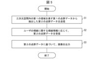
- FIG. 5 is a flow diagram showing the flow of the video transmission method. As shown in FIG. 5, the video transmission method includes steps S1 to S3.
- the transmission unit 11 transmits the second point cloud data extracted from the first point cloud data representing the first region in the three-dimensional space (S1).
- the receiving unit 21 receives second point cloud data in accordance with line-of-sight information regarding the user's line of sight (S2).
- the output unit 22 outputs an image to be displayed to the user based on the second point cloud data (S3).
- step S2 the second point cloud data is received according to the line-of-sight information regarding the user's line of sight. Therefore, it is possible to display a region where the user's line of sight is directed with a high point cloud density and a region where the user's line of sight is not directed with a low point cloud density. can be provided.
- step S2 since the point cloud data is received according to the user's line-of-sight information, the amount of data to be received can be reduced, and the communication load can be reduced.
- the point cloud density is increased in the area where the user's line of sight is directed, and the point cloud density is gradually decreased as the distance from the area increases. can.
- step S1 for example, by broadcast distribution or multicast distribution, the second point cloud data is distributed to a plurality of users, and in step S2, according to the line-of-sight information regarding each user's line of sight, the second point cloud data is received, and in step S3, an image is output based on the second point cloud data corresponding to each user, so that high-quality video corresponding to the line of sight of a plurality of users is distributed. It becomes possible to
- the transmission unit 11 performs multicast distribution or broadcast distribution of the second point cloud data, thereby enabling data distribution to multiple users without requiring additional communication resources.
- the distribution method is not limited to broadcast distribution and multicast distribution as described above.
- FIG. 6 is a block diagram showing the functional configuration of the video transmission system 100'.
- the video transmission system 100' includes a server device 1 and a terminal device 2.
- the video transmission system 100' includes a server device 1 and a terminal device 2.
- the server device 1 includes a transmitter 11 , a space divider 12 , a point cloud data extractor 13 and a transmission information generator 14 .
- the transmission unit 11 is a configuration that implements transmission means in this exemplary embodiment.
- the space division unit 12 is a configuration that implements space division means in this exemplary embodiment.
- the point cloud data extraction unit 13 is a configuration that implements the point cloud data extraction means in this exemplary embodiment.
- the transmission information generation unit 14 is a configuration that implements transmission information generation means in this exemplary embodiment.
- the space division unit 12 divides the image of the shooting target space in the three-dimensional space into a plurality of areas. For example, as shown in FIG. 2, the space division unit 12 divides the shooting target space into a plurality of areas. One of the regions divided by the space dividing section 12 is called a first region. A first region of the imaging target space includes first point cloud data.
- the point cloud data extraction unit 13 extracts second point cloud data from the point cloud data representing the first region after being divided by the space dividing unit 12 .
- extracting the second point cloud data from the first point cloud data means, as described in the first exemplary embodiment, an example of split data obtained by splitting the first point cloud data. It means generating the second point cloud data from the first point cloud data such that the second point cloud data includes at least one of them.
- the point cloud data extraction unit 13 may divide the first point cloud data and extract second point cloud data including a plurality of point cloud data with different point cloud densities.
- the point cloud data extraction unit 13 divides the first point cloud data into a plurality of point cloud data, for example, divided data A to divided data D as shown in FIG. It is good also as a structure which extracts. As described in the first exemplary embodiment, it is possible to reconstruct the first point cloud data by synthesizing the divided data A to D.
- the transmission unit 11 transmits the second point cloud data.
- transmission of the second point cloud data is performed via a network as an example.
- a network as an example.
- wireless LAN Local Area Network
- wired LAN Wireless Local Area Network
- WAN Wide Area Network
- public line network public line network
- mobile data communication network Or a combination of these networks can be used.
- the transmission unit 11 may transmit fourth point cloud data extracted from third point cloud data representing a second area different from the first area in the three-dimensional space.
- third point cloud data representing a second area different from the first area in the three-dimensional space.
- the point cloud data extraction unit 13 divides the third point cloud data representing the second region, 4 point cloud data is extracted.
- the same method as the above-described method for extracting the second point cloud data from the first point cloud data is used. can be used.
- the transmission information generation unit 14 generates transmission information regarding the second point cloud data.
- the transmission information generating unit 14 for example, provides spatial information of the divided area, the number of points included in the point cloud data for each divided data, the bit rate of the point cloud data, the channel information for distributing the second point cloud data, and the like. and output to the transmission unit 11 .
- An example of spatial information is the coordinates of the eight corners of a rectangular parallelepiped that constitutes each divided space.
- the transmission information includes, for example, the number of point groups of divided data A to D shown in FIG. 3 and channel information for distributing the divided data (IP address of multicast group in IP multicast, etc.). Note that, as shown in FIG. 7, the divided areas themselves may be named and used as spatial information.
- the transmission information includes information about the size of the second point cloud data.
- the information about the size of the second point cloud data is, for example, the number of points of the second point cloud data, the point cloud density of the second point cloud data, and the data capacity of the second point cloud data.
- the transmission information includes information on the position occupied by the first area in the shooting target space, information on the correspondence relationship between the first area and the second point cloud data, and information on the bit rate of the second point cloud data. may contain at least one of
- the information about the correspondence relationship between the first region and the second point cloud data is, for example, information indicating which of the divided regions the second point cloud data corresponds to. is. Further, it may include information on the transmission path for transmitting the second point cloud data.
- the transmission unit 11 transmits the second point cloud data and transmission information. At this time, when the second point cloud data includes a plurality of divided data, the transmitting unit 11 transmits transmission information to the terminal device 2 in association with each of the plurality of divided data.
- the server device 1 may use a different transmission path for each piece of divided data when distributing the 3D video.
- the transmission information may include information on the transmission line that transmits the divided data. For example, divided data with a high point cloud density is distributed using a transmission line that can be transmitted at high speed. Also, divided data with a low point cloud density is distributed using a separate transmission line with a relatively low speed.
- the terminal device 2 includes a line-of-sight information collection unit 23 that acquires line-of-sight information indicating the user's line of sight, and a first point cloud data representing a first region in the three-dimensional space.
- a receiving unit 21 that receives the second point cloud data according to line-of-sight information, and an output unit 22 that outputs an image to be displayed to the user based on the second point cloud data received by the receiving unit 21.
- an acquired data specifying unit 24 for specifying point cloud data to be acquired. Specific processing by each unit included in the terminal device 2 will be described later.
- the receiving unit 21 of the terminal device 2 may receive viewpoint information indicating from which direction the user views the three-dimensional space represented by the point cloud data. For example, in FIG. 7, the user is viewing the three-dimensional space represented by the point cloud data from the left viewpoint.
- the receiving unit 21 is a configuration that implements receiving means in this exemplary embodiment.
- the output unit 22 is a configuration that implements output means in this exemplary embodiment.
- the line-of-sight information collection unit 23 is a configuration that implements line-of-sight information acquisition means in this exemplary embodiment.
- the acquired data specifying unit 24 is a configuration that implements specifying means in this exemplary embodiment.
- FIG. 7 is a diagram for explaining how the receiving unit 21 receives the point cloud data.
- the receiving unit 21 receives the second point cloud data according to the line-of-sight information of the user collected by the line-of-sight information collecting unit 23 such as VR goggles. For example, as shown in FIG. 7, when the user's line of sight is directed to the area b2, the receiving unit 21 receives the second point cloud data of the area b2 so that the point cloud density of the area b2 is high. .
- the acceleration sensor provided in the VR goggles , an angular velocity sensor, or the like may be used to collect the line-of-sight information of the user.
- the line-of-sight information collection unit 23 may acquire image data captured by a camera provided at the viewing location where the user is present, and the line-of-sight information collection unit 23 may analyze the captured data to collect the user's line-of-sight information. good.
- the receiving unit 21 calculates the second point clouds of the regions b1, b3, b5, and b8 so that the regions b1, b3, b5, and b8 adjacent to the region b2 have a lower point cloud density than the region b2. Receive data.
- the terminal device 2 may include an acquired data specifying unit 24 that specifies the image quality to be displayed to the user, and the receiving unit 21 may receive the second point cloud data according to the specified image quality. For example, when the user's line of sight is directed to the first area shown in FIG. Identify and receive split data with high density. Further, the image of the area other than the first area, to which the user's line of sight is not directed, has a lower image quality than the image of the first area. Identify and receive data.
- the transmission unit 11 of the server device 1 extracts fourth point cloud data from the third point cloud data representing a second area different from the first area in the three-dimensional space and further transmits the fourth point cloud data.
- the receiving unit 21 of the terminal device 2 receives the fourth point cloud data in accordance with the line-of-sight information, and the output unit 22 outputs the second point cloud data and the fourth point cloud data to the user You may make it output the image displayed with respect to.
- the transmitting unit 11 of the server device 1 transmits the second point cloud data and the transmission information
- the receiving unit 21 of the terminal device 2 transmits the second point cloud data according to the line-of-sight information and the received transmission information.
- the data may be received, and the output unit 22 may output an image to be displayed to the user based on the second point cloud data and the transmission information.
- FIG. 8 is a diagram for explaining a case where a plurality of users receive point cloud data.
- the reception unit 21 of the terminal device 2 of the first user adjusts the area b2 so that the point cloud density of the area b2 is high.
- the receiving unit 21 of the terminal device 2 of the first user adjusts the point cloud density of the regions b4, b6, etc. distant from the region b2 so that the point cloud density of the regions b4, b3, b5, etc. is even lower than that of the regions b1, b3, b5, etc. , b6, etc. are received.
- the receiving unit 21 of the terminal device 2 of the second user selects the second points of the region b8 so that the point cloud density of the region b8 is high.
- Receive group data Further, the receiving unit 21 of the terminal device 2 of the second user adjusts the area b5, b7, b9 so that the point cloud density of the areas b5, b7, b9, etc. adjacent to the area b8 is lower than that of the area b8.
- receive second point cloud data such as
- the receiving unit 21 of the terminal device 2 of the second user adjusts the point cloud density of the regions b4, b6, etc. distant from the region b8 so that the point cloud density of the regions b4, b7, b9, etc. is even lower than that of the regions b5, b7, b9, etc. , b6, etc. are received.
- the terminal devices 2 of the first user and the second user can receive and output the point cloud data with the optimum point cloud density according to their line-of-sight information.
- the acquisition data specifying unit 24 specifies the second point cloud data to be acquired based on the viewing quality-related evaluation function specified by the display distance of the first region and the point cloud density of the second point cloud data.
- the display distance represents the distance from the user's viewpoint to an arbitrary area in the three-dimensional space represented by the point cloud data.
- the display distance of the first area represents the distance from the user's viewpoint to the first area in the three-dimensional space represented by the point cloud data.
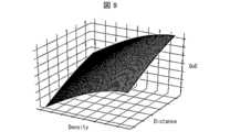
- FIG. 9 is a diagram for explaining the evaluation function regarding viewing quality.
- the viewing quality QoE
- the viewing quality is defined by the point cloud density (Density) of the point cloud data and the display distance to the area where the user's line of sight is directed (hereinafter sometimes referred to as the gaze area). (Distance).
- a function representing the relationship between the point cloud density and the display distance to the gaze area is used as an evaluation function for viewing quality.
- the acquired data specifying unit 24 determines the viewing quality determined by the point cloud density of each divided area (if the distributed point cloud data is divided, the total value of the point cloud densities of the divided data) and the display distance.
- the priority of the divided data is specified for each region so as to maximize the total value of .
- the receiving unit 21 receives the divided data from the server device 1 according to the priority specified by the acquired data specifying unit 24 .
- the acquired data specifying unit 24 maximizes the total value of the viewing quality determined by the bit rate of the point cloud data representing each region distributed from the server device 1 and the display distance. , the priority of the divided data may be specified.
- Total viewing quality ⁇ U(b(n, i), d(n)) (Formula 1) ⁇ b(n, i) ⁇ min (radio band, processing capacity maximum reception rate) (Formula 2)
- the acquired data specifying unit 24 specifies the priority of the divided data for each region so that the total viewing quality of (Formula 1) is maximized within the range where the constraint condition of (Formula 2) is satisfied.
- the upper limit of the number of point cloud data that can be obtained is limited by the terminal capability of the terminal device 2 and the ever-changing network bandwidth.
- the point cloud data is received according to the priority so that the upper limit of .
- the output unit 22 synthesizes the received point cloud data corresponding to each divided area so as to integrate them, and performs display processing.
- the output unit 22 applies processing for improving viewing quality, such as changing the point size of the second point cloud data and mesh processing, to the second point cloud data, and then the point cloud data after the application is It is also possible to adopt a configuration in which an image representing the image is displayed.
- Examples of terminal devices include VR goggles, televisions, PCs (Personal Computers), tablet terminals, smart phones, etc., but these are not intended to limit the present exemplary embodiment.
- FIG. 10 is a flow diagram showing the flow of the video transmission method. As shown in FIG. 10, the video transmission method includes steps S11 to S18.
- the space division unit 12 of the server device 1 divides the shooting target space into a plurality of areas (S11). Then, the point cloud data extraction unit 13 of the server device 1 divides the first point cloud data representing the first region, and generates second point cloud data including a plurality of point cloud data with different point cloud densities. Extract (S12).
- the transmission information generation unit 14 of the server device 1 generates transmission information from the area of the point cloud data extracted by the point cloud data extraction unit 13, the point cloud density of the point cloud data, etc. (S13), and the transmission unit 11 transmits transmission information to the terminal device 2 .
- the acquired data specifying unit 24 of the terminal device 2 acquires the user's line-of-sight information collected by the line-of-sight information collecting unit 23 (S14).
- the acquisition data specifying unit 24 acquires the transmission information, and specifies point cloud data to be acquired from the user's line-of-sight information and the transmission information (S15 ), and notifies the receiving unit 21 of the identified point cloud data.
- the receiving unit 21 of the terminal device 2 receives only the point cloud data notified from the acquired data specifying unit 24 (S16), and receives The obtained point cloud data is output to the output unit 22 .
- the output unit 22 of the terminal device 2 synthesizes the point cloud data received by the receiving unit 21 (S17), and outputs the synthesized image (S18). Thereafter, the processes of steps S11 to S18 are repeated. Therefore, each time the line-of-sight information of the user is changed, in steps S15 to S18, point cloud data corresponding to the changed line-of-sight information is received, the point cloud data are combined, and an image is output. Become.
- FIG. 11 is a flow diagram showing the flow of the video reception method by the terminal device 2 according to the exemplary embodiment 2 of the present invention.
- the acquired data specifying unit 24 determines the target distance to the gaze region obtained from the user's line-of-sight information collected by the line-of-sight information collecting unit 23, the transmission information received from the server device 1, the target distance and the point cloud density, and (S21).
- the receiving unit 21 selects a plurality of pieces of point cloud data distributed from the server device 1 to form a three-dimensional image. receive the point cloud data necessary for (S22).
- the output unit 22 integrates and synthesizes the received point cloud data corresponding to each area, and performs display processing (S23).
- each part of the server device 1 may be implemented in separate devices on the cloud.
- the transmission unit 11 and the space division unit 12 may be one device
- the point cloud data extraction unit 13 and the transmission information generation unit 14 may be one device. These may be implemented in one device or in separate devices. For example, when implemented in separate devices, information of each unit is transmitted and received via a communication network to advance processing.
- each part of the terminal device 2 may be implemented in separate devices on the cloud.
- the receiving unit 21 and the output unit 22 may be one device
- the line-of-sight information collecting unit 23 and the acquired data specifying unit 24 may be one device. These may be implemented in one device or in separate devices. For example, when implemented in separate devices, information of each unit is transmitted and received via a communication network to advance processing.
- the transmission information generation unit 14 generates information about the position occupied by the first area in the shooting target space, the first area and the first area. and generating transmission information including at least one of information on the correspondence with the second point cloud data and information on the bit rate of the second point cloud data. Therefore, the output unit 22 can appropriately synthesize and display the second point cloud data based on the transmission information.
- the acquired data specifying unit 24 acquires the second point cloud data based on the viewing quality-related evaluation function specified by the display distance to the first region and the point cloud density of the second point cloud data. identify. Therefore, the output unit 22 can display the 3D video with high viewing quality.
- the server device 1 side can obtain the point cloud data of each region according to the line of sight of each user. It is possible to reduce the load on the server device 1 as compared with the case of extracting .
- the server device 1 distributes the point cloud data by wireless communication, it is assumed that the wireless band is insufficient and all the point cloud data cannot be distributed.
- the server device 1 acquires user's line-of-sight information (gazing area) from the terminal device 2 and distributes point cloud data based on the line-of-sight information of a plurality of users, thereby reducing the consumption band. It is intended to reduce
- FIG. 12 is a block diagram showing the functional configuration of a video transmission system 100A according to exemplary embodiment 3 of the present invention.
- a video transmission system 100A includes a server device 1A and a terminal device 2A.
- the server device 1A also includes a space division unit 12, a point cloud data extraction unit 13, a transmission information generation unit 14, a communication unit 15, and a transmission data identification unit 16.
- the communication unit 15 transmits the second point cloud data and transmission information to the terminal device 2A, and receives the user's gaze region from the terminal device 2A.
- the server device 1A further includes a transmission data identification unit 16 in addition to the configuration of the server device 1 according to exemplary embodiment 2, and instead of the transmission unit 11, the communication unit 15 It has
- the communication unit (transmitting unit) 15 transmits the second point cloud data according to the line-of-sight information of the user. Specifically, first, the transmission data specifying unit 16 determines the distribution priority for the point cloud data based on the line-of-sight information (gazing area) of a plurality of users received by the communication unit 15. Identify point cloud data to be transmitted according to distribution performance and network bandwidth constraints. Then, the communication unit 15 distributes the point cloud data according to the distribution priority determined by the transmission data specifying unit 16 .
- the transmission data specifying unit 16 distributes point cloud data (for example, divided data C shown in FIG. 3) having the minimum point cloud density obtained by dividing all regions, and processing performance and network bandwidth As long as there is room in the user's attention area, point cloud data is assigned to the empty band in order from the point cloud data with the highest point cloud density among the divided multiple point cloud data according to the number of user's gaze areas. You may do so.
- point cloud data for example, divided data C shown in FIG. 3
- FIG. 13 is a diagram for explaining a method of determining distribution priority according to the number of gaze areas of multiple users.
- a score is assigned according to the distance between each of a plurality of users and each divided area. As shown in FIG. 13, the smallest score is assigned to the area close to the area where the user is gazing on the left side, and the greater the distance, the greater the score.
- the transmission data specifying unit 16 adds up the scores of all the users in each divided area and assigns a score. The distribution priority of the area with the minimum score is increased, and the distribution priority is decreased as the score increases.
- FIG. 14 is a flow chart showing the flow of the video transmission method by the video transmission system 100A according to the exemplary embodiment 3 of the present invention.
- the space dividing unit 12 acquires point cloud data of the shooting target space (S31), and spatially divides the point cloud data (S32).
- the point cloud data extracting unit 13 converts the first point cloud data representing the first region spatially divided by the space dividing unit 12 into point cloud data having different point cloud densities. Extract (S33).
- the communication unit 15 determines whether or not there is a processing performance of the server device 1A capable of distributing all of the extracted point cloud data and a communication band between the terminal device 2A and the communication network (S34).
- step S34 If all of the extracted point cloud data can be delivered (S34, Yes), the process proceeds to step S36. If even a part of all the extracted point cloud data cannot be distributed (S34, No), the transmission data specifying unit 16 selects points to be distributed based on the gaze areas and distance information of a plurality of users. Group data is determined (S35).
- step S36 the communication unit 15 distributes the point cloud data determined to be distributed by the transmission data specifying unit 16 by broadcast distribution or multicast distribution, and ends the process.
- the server device 1 stores the generated divided data in the server device 1, and the terminal device 2 accesses the server device 1 and receives the divided data according to the line of sight of the user, so that the video can be viewed on demand. can also be configured.
- the server device 1 redistributes the recorded 3D video
- the second point cloud data is prepared by referring to the gaze regions of the plurality of users when the 3D video was previously distributed, and the recorded 3D video is prepared.
- the original video may be redistributed.
- the server device 1A when the server device 1A distributes 3D video, it records the gaze areas of multiple users in association with each scene of the 3D video. Then, when the server device 1A redistributes the same 3D video, it refers to the gaze areas of the previous users to determine point cloud data to be distributed, and transmits the 3D video. Therefore, it is possible to distribute the divided data so that the image quality is high for the part that was watched by a plurality of users last time.
- the server device 1A may prepare the second point cloud data by referring to the gaze area of one user, and redistribute the recorded 3D video. For example, when the server device 1A distributes the 3D video, it records the region of interest of a certain user in association with each scene of the 3D video. Then, when the server device 1A redistributes the 3D video to the same user, it refers to the gaze region of the user to determine point cloud data to be distributed, and transmits the 3D video. Therefore, it is possible to distribute the divided data so that the image quality is high for the part that the user has been paying attention to.
- the transmission data specifying unit 16 distributes point cloud data based on the gaze regions of a plurality of users received by the communication unit 15. Determine the priority and identify the point cloud data to be sent. Therefore, the communication unit 15 can transmit the point cloud data in accordance with the distribution performance of the server device 1A and the restriction of the network band.
- FIG. 15 is a block diagram showing the functional configuration of a video transmission system 100B according to exemplary embodiment 4 of the present invention.
- a video transmission system 100B includes a server device 1B and a terminal device 2 .
- the server device 1B also includes a transmission unit 11, a space division unit 12, a point cloud data extraction unit 13, a transmission information generation unit 14, and a division area recognition unit 17.
- the divided area recognition unit 17 recognizes a person or an object, and specifies an area for each person or object, or for each part of the human body.
- the space division unit 12 divides the space according to the areas identified by the division area recognition unit 17. For example, a region is divided for each part of the human body, and the space corresponding to the region is divided. For example, when the user is watching a soccer game, the point cloud data of the soccer player's foot is taken as one unit, and the point cloud data extracting unit 13 extracts the point cloud data to generate a second point cloud. Extract data. Subsequent processing is the same as that described in the first to third exemplary embodiments.
- the divided area recognition unit 17 identifies an area for each person or object, or for each part of the human body. Therefore, it is possible to provide 3D images with the same quality for each person or object, or for each part of the human body.
- FIG. 16 is a block diagram showing the functional configuration of a video transmission system 100C according to Exemplary Embodiment 5 of the present invention.
- a video transmission system 100C includes a server device 1C and a terminal device 2 .
- the server device 1C also includes a transmission unit 11, a space division unit 12, a point cloud data extraction unit 13, a transmission information generation unit 14, and a gaze point identification unit 18.
- the attention point specifying unit 18 designates an area such as a person or an object that the viewer wishes to pay attention to on the distribution side, and designates the area (hereinafter referred to as a designated attention point) so as to have a high image quality. For example, a mark that can be detected by a sensor is added to an object or area to be focused. Then, the gaze point specifying unit 18 analyzes the acquired image and specifies the area to which the user wants to draw attention by, for example, recognizing the marked target to which one wants to draw attention.
- the server device 1C distributes a video of a stage such as a play
- a mark that can be detected by the sensor is attached to a person or object to be noticed. This allows the gaze point identifying unit 18 to recognize the marked target to which attention should be paid.
- various sensors can be used as long as they are sensors that acquire information of the shooting target space. A camera or the like can be used as an example of the sensor.
- the transmission information generation unit 14 generates transmission information so that the attention area specified by the gaze point specifying unit 18 has high image quality. Further, the point cloud data extraction unit 13 extracts the second point cloud data so that the attention area specified by the gaze point specifying unit 18 has high image quality. Subsequent processing is the same as that described in the first to third exemplary embodiments.
- the server device 1C may have a configuration that restricts the line of sight of the viewer. For example, the server device 1C transmits an instruction to invalidate the line-of-sight information collected by the line-of-sight information collection unit 23 to the terminal device 2 .
- the acquired data specifying unit 24 of the terminal device 2 specifies the point cloud data regardless of the viewer's line-of-sight information. Thus, regardless of the line of sight of the viewer, it is possible to display the person or object to be noticed on the terminal device 2 with high image quality.
- a configuration may be provided that limits the directions in which the user can view the distributed video. This allows the user to view the video from a direction suitable for theater viewing.
- the gaze point specifying unit 18 specifies the gaze specified point so as to have high image quality. Therefore, it is possible for the distribution side to specify an area such as a person or an object that the viewer wants to pay attention to, and to provide 3D video of the specified area with high image quality.
- illustrations, photographs, etc. are superimposed on the three-dimensional video that is transmitted to the terminal device 2A.
- FIG. 17 is a block diagram showing the functional configuration of a video transmission system 100D according to exemplary embodiment 6 of the present invention.
- a video transmission system 100D includes a server device 1D and a terminal device 2A.
- the server device 1D also includes a space division unit 12, a point cloud data extraction unit 13, a transmission information generation unit 14, a communication unit 15, and a combined data reception unit 19.
- the composite data receiving unit 19 receives data representing an illustration to be superimposed on the point cloud data of the three-dimensional space being transmitted from the user who is distributing the video.
- the communication unit 15 of the server device 1D transmits the received data representing the illustration to the terminal device 2A together with the point cloud data.
- the output unit 22 of the terminal device 2A displays the received illustration superimposed on the point cloud data.
- the communication unit 25 of the terminal device 2A transmits data such as an illustration specified by the user viewing the video to the server device 1D.
- the communication unit 15 of the server device 1D receives data such as illustrations transmitted from the terminal device 2A.
- the combined data receiving unit 19 also receives data such as an illustration received by the communication unit 15 and notifies the transmission information generating unit 14 of the position, color, and the like of the illustration.
- the transmission information generation unit 14 generates transmission information from the illustration, the position and color of the illustration, etc. in response to the notification from the combined data reception unit 19 . Further, the point cloud data extraction unit 13 superimposes the illustration on the point cloud data, extracts the point cloud data on which the illustration is superimposed, and extracts the second point cloud data. Subsequent processing is the same as that described in the first to third exemplary embodiments.
- the data such as the illustration or the like is not transmitted to the server device 1D, but is transmitted to the terminal device 2A of the viewing user.
- the terminal device 2A may have a function of superimposing an illustration or the like on the video.
- the terminal device 2A receives data such as an illustration designated by the user from the user viewing the video.
- Data such as an illustration received from the user is superimposed on the video received from the server device 1D and displayed.
- the point cloud data extraction unit 13 superimposes the illustration on the point cloud data, and extracts the second image from the point cloud data on which the illustration is superimposed. Added point cloud data extraction. Therefore, it is possible for the user to insert his or her favorite illustration or the like into the three-dimensional video.
- Some or all of the functions of the server devices 1, 1A to 1D and the terminal devices 2, 2A may be implemented by hardware such as integrated circuits (IC chips), or may be implemented by software.
- the server devices 1, 1A to 1D and the terminal devices 2, 2A are realized, for example, by computers that execute program instructions, which are software for realizing each function.
- An example of such a computer (hereinafter referred to as computer C) is shown in FIG.
- Computer C comprises at least one processor C1 and at least one memory C2.
- a program P for operating the computer C as the server devices 1, 1A to 1D and the terminal devices 2, 2A is recorded in the memory C2.
- the processor C1 reads the program P from the memory C2 and executes it, thereby implementing the functions of the server devices 1, 1A to 1D and the terminal devices 2, 2A.
- processor C1 for example, CPU (Central Processing Unit), GPU (Graphic Processing Unit), DSP (Digital Signal Processor), MPU (Micro Processing Unit), FPU (Floating point number Processing Unit), PPU (Physics Processing Unit) , a microcontroller, or a combination thereof.
- memory C2 for example, a flash memory, HDD (Hard Disk Drive), SSD (Solid State Drive), or a combination thereof can be used.
- the computer C may further include a RAM (Random Access Memory) for expanding the program P during execution and temporarily storing various data.
- Computer C may further include a communication interface for sending and receiving data to and from other devices.
- Computer C may further include an input/output interface for connecting input/output devices such as a keyboard, mouse, display, and printer.
- the program P can be recorded on a non-temporary tangible recording medium M that is readable by the computer C.
- a recording medium M for example, a tape, disk, card, semiconductor memory, programmable logic circuit, or the like can be used.
- the computer C can acquire the program P via such a recording medium M.
- the program P can be transmitted via a transmission medium.
- a transmission medium for example, a communication network or broadcast waves can be used.
- Computer C can also obtain program P via such a transmission medium.
- (Appendix 1) transmitting means for transmitting second point cloud data extracted from first point cloud data representing a first region in a three-dimensional space; Receiving means for receiving the second point cloud data according to line-of-sight information related to the user's line of sight; and output means for outputting an image to be displayed to the user based on the second point cloud data.
- Appendix 2 comprising specifying means for specifying the image quality to be displayed to the user;
- the video transmission system according to appendix 1, wherein the receiving means receives the second point cloud data according to the specified image quality.
- the receiving means to receive the second point cloud data corresponding to the image quality of the video.
- appendix 3 The video transmission according to appendix 1 or 2, wherein the second point cloud data includes a plurality of point cloud data extracted from the first point cloud data and having a point cloud density different from that of the first point cloud data. system.
- the output means synthesizes and outputs any of the plurality of point cloud data, thereby making it possible to display images with different qualities.
- the transmission means is Transmitting fourth point cloud data extracted from third point cloud data representing a second region different from the first region in the three-dimensional space;
- the receiving means receives the fourth point cloud data according to the line-of-sight information,
- the video transmission system according to any one of Appendices 1 to 3, wherein the output means outputs an image to be displayed to the user based on the second point cloud data and the fourth point cloud data.
- the transmitting means to transmit point cloud data with different point cloud densities for each region in the three-dimensional space.
- the video transmission system comprises transmission information generating means for generating transmission information regarding the second point cloud data, The transmission means transmits the second point cloud data and the transmission information, The receiving means receives the second point cloud data according to the line-of-sight information and the received transmission information, 5.
- the video transmission system according to any one of appendices 1 to 4, wherein the output means outputs an image to be displayed to the user based on the second point cloud data and the transmission information.
- the output means can output an image based on the second point cloud data in accordance with the transmission information, and it is possible to suitably display the 3D video.
- the transmission information is information about the position of the first region in the three-dimensional space;
- the output means can more preferably display the 3D video.
- Appendix 7 The video transmission system according to any one of Appendices 1 to 6, wherein the transmission means transmits the second point cloud data according to the line-of-sight information of the user.
- the transmission means can easily specify the second point cloud data to be transmitted according to the line-of-sight information of the user.
- the receiving means it is possible for the receiving means to receive suitable video according to the line of sight of the user.
- Appendix 9 comprising specifying means for specifying the image quality to be displayed to the user;
- the receiving means to receive the second point cloud data corresponding to the image quality of the video.
- appendix 10 The terminal device according to appendix 8 or 9, wherein the second point cloud data includes a plurality of point cloud data extracted from the first point cloud data and having a point cloud density different from that of the first point cloud data.
- the output means synthesizes and outputs any of the plurality of point cloud data, thereby making it possible to display images with different qualities.
- the receiving means receives fourth point cloud data extracted from third point cloud data representing a second area different from the first area in the three-dimensional space according to the line-of-sight information. , 11. The terminal device according to any one of appendices 8 to 10, wherein the output means outputs an image to be displayed to the user based on the second point cloud data and the fourth point cloud data.
- the receiving means to receive point cloud data with different point cloud densities for each region in the three-dimensional space.
- the receiving means receives the second point cloud data according to the line-of-sight information and transmission information regarding the received second point cloud data, 12.
- the terminal device according to any one of attachments 8 to 11, wherein the output means outputs an image to be displayed to the user based on the second point cloud data and the transmission information.
- the output means can output an image based on the second point cloud data in accordance with the transmission information, and it is possible to suitably display the 3D video.
- the video transmission method includes: generating transmission information about the second point cloud data; In the step of transmitting the second point cloud data, transmitting the second point cloud data and the transmission information; In the step of receiving the second point cloud data, receiving the second point cloud data according to the line-of-sight information and the received transmission information; In the step of outputting the image, 17.
- the video transmission method according to any one of appendices 13 to 16, wherein an image to be displayed to the user is output based on the second point cloud data and the transmission information.
- a server apparatus comprising: a transmission unit that transmits the second point cloud data.
- Appendix 22 9. The video transmission system according to any one of Appendices 1 to 8, wherein the output means synthesizes and displays a plurality of point cloud data included in the second point cloud data.
- Appendix 23 at least one processor, the processor transmitting second point cloud data extracted from first point cloud data representing a first region in three-dimensional space; A process of receiving the second point cloud data according to line-of-sight information about the user's line of sight; A video transmission system for executing a process of outputting an image based on the second point cloud data.
- the video transmission system may further include a memory, and the memory stores a program for causing the processor to execute the transmission process, the reception process, and the output process. may have been Also, this program may be recorded in a computer-readable non-temporary tangible recording medium.
- Appendix 24 at least one processor, wherein the processor acquires line-of-sight information indicating a user's line of sight; A process of receiving second point cloud data extracted from first point cloud data representing a first region in a three-dimensional space according to the line-of-sight information; and outputting an image based on the received second point cloud data.
- the terminal device may further include a memory, and the memory stores a program for causing the processor to execute the acquiring process, the receiving process, and the outputting process.
- this program may be recorded in a computer-readable non-temporary tangible recording medium.
- Appendix 25 comprising at least one processor, wherein the processor divides an image of a shooting target space in a three-dimensional space into a plurality of regions; A process of extracting second point cloud data from the point cloud data representing the first region after division; and a process of transmitting the second point cloud data.
- the server device may further include a memory, and the memory stores a program for causing the processor to execute the dividing process, the extracting process, and the transmitting process. may be Also, this program may be recorded in a computer-readable non-temporary tangible recording medium.
Landscapes
- Engineering & Computer Science (AREA)
- Computer Vision & Pattern Recognition (AREA)
- Physics & Mathematics (AREA)
- General Physics & Mathematics (AREA)
- Theoretical Computer Science (AREA)
- Computer Networks & Wireless Communication (AREA)
- Databases & Information Systems (AREA)
- Multimedia (AREA)
- Signal Processing (AREA)
- Information Transfer Between Computers (AREA)
Priority Applications (2)
| Application Number | Priority Date | Filing Date | Title |
|---|---|---|---|
| JP2023544878A JP7616401B2 (ja) | 2021-09-01 | 2021-09-01 | 映像送信システム、端末装置および映像送信方法 |
| PCT/JP2021/032150 WO2023032085A1 (ja) | 2021-09-01 | 2021-09-01 | 映像送信システム、端末装置および映像送信方法 |
Applications Claiming Priority (1)
| Application Number | Priority Date | Filing Date | Title |
|---|---|---|---|
| PCT/JP2021/032150 WO2023032085A1 (ja) | 2021-09-01 | 2021-09-01 | 映像送信システム、端末装置および映像送信方法 |
Publications (1)
| Publication Number | Publication Date |
|---|---|
| WO2023032085A1 true WO2023032085A1 (ja) | 2023-03-09 |
Family
ID=85410957
Family Applications (1)
| Application Number | Title | Priority Date | Filing Date |
|---|---|---|---|
| PCT/JP2021/032150 Ceased WO2023032085A1 (ja) | 2021-09-01 | 2021-09-01 | 映像送信システム、端末装置および映像送信方法 |
Country Status (2)
| Country | Link |
|---|---|
| JP (1) | JP7616401B2 (https=) |
| WO (1) | WO2023032085A1 (https=) |
Citations (3)
| Publication number | Priority date | Publication date | Assignee | Title |
|---|---|---|---|---|
| JP2012178133A (ja) * | 2011-02-03 | 2012-09-13 | Nippon Telegr & Teleph Corp <Ntt> | 被写体認識装置、被写体認識方法及び被写体認識プログラム |
| JP2015197329A (ja) * | 2014-03-31 | 2015-11-09 | 三菱重工業株式会社 | データ伝送システム、データ伝送装置、データ伝送方法、及びデータ伝送プログラム |
| WO2019065536A1 (ja) * | 2017-09-26 | 2019-04-04 | パナソニック インテレクチュアル プロパティ コーポレーション オブ アメリカ | 再構成方法および再構成装置 |
Family Cites Families (3)
| Publication number | Priority date | Publication date | Assignee | Title |
|---|---|---|---|---|
| CN111727463B (zh) * | 2018-01-19 | 2025-04-11 | 松下电器(美国)知识产权公司 | 三维数据编码方法、三维数据解码方法、三维数据编码装置、以及三维数据解码装置 |
| WO2020013249A1 (ja) * | 2018-07-13 | 2020-01-16 | パナソニック インテレクチュアル プロパティ コーポレーション オブ アメリカ | 三次元データ符号化方法、三次元データ復号方法、三次元データ符号化装置、及び三次元データ復号装置 |
| WO2021141221A1 (ko) * | 2020-01-07 | 2021-07-15 | 엘지전자 주식회사 | 포인트 클라우드 데이터 송신 장치, 포인트 클라우드 데이터 송신 방법, 포인트 클라우드 데이터 수신 장치 및 포인트 클라우드 데이터 수신 방법 |
-
2021
- 2021-09-01 WO PCT/JP2021/032150 patent/WO2023032085A1/ja not_active Ceased
- 2021-09-01 JP JP2023544878A patent/JP7616401B2/ja active Active
Patent Citations (3)
| Publication number | Priority date | Publication date | Assignee | Title |
|---|---|---|---|---|
| JP2012178133A (ja) * | 2011-02-03 | 2012-09-13 | Nippon Telegr & Teleph Corp <Ntt> | 被写体認識装置、被写体認識方法及び被写体認識プログラム |
| JP2015197329A (ja) * | 2014-03-31 | 2015-11-09 | 三菱重工業株式会社 | データ伝送システム、データ伝送装置、データ伝送方法、及びデータ伝送プログラム |
| WO2019065536A1 (ja) * | 2017-09-26 | 2019-04-04 | パナソニック インテレクチュアル プロパティ コーポレーション オブ アメリカ | 再構成方法および再構成装置 |
Also Published As
| Publication number | Publication date |
|---|---|
| JP7616401B2 (ja) | 2025-01-17 |
| JPWO2023032085A1 (https=) | 2023-03-09 |
Similar Documents
| Publication | Publication Date | Title |
|---|---|---|
| US11217006B2 (en) | Methods and systems for performing 3D simulation based on a 2D video image | |
| CN112489182B (zh) | 用于生成图像的系统、方法和存储介质 | |
| US10582191B1 (en) | Dynamic angle viewing system | |
| JP6415675B1 (ja) | 生成装置、生成方法及びプログラム | |
| EP3759683B1 (en) | Image processing device, encoding device, decoding device, image processing method, program, encoding method, and decoding method | |
| JP2019054488A (ja) | 提供装置および提供方法、プログラム | |
| US11055917B2 (en) | Methods and systems for generating a customized view of a real-world scene | |
| CN112738495A (zh) | 虚拟视点图像生成方法、系统、电子设备及存储介质 | |
| CN112738534A (zh) | 数据处理方法及系统、服务器和存储介质 | |
| TW202029742A (zh) | 影像合成 | |
| EP3742402B1 (en) | Generation of a virtual viewpoint image | |
| KR20180120456A (ko) | 파노라마 영상을 기반으로 가상현실 콘텐츠를 제공하는 장치 및 그 방법 | |
| WO2022224964A1 (ja) | 情報処理装置及び情報処理方法 | |
| CN112738646A (zh) | 数据处理方法、设备、系统、可读存储介质及服务器 | |
| JP6450305B2 (ja) | 情報取得装置、情報取得方法及び情報取得プログラム | |
| US11315306B2 (en) | Systems and methods for processing volumetric data | |
| JP2019103126A (ja) | カメラシステム、カメラ制御装置、カメラ制御方法及びプログラム | |
| WO2022181379A1 (ja) | 画像処理装置、画像処理方法、及びプログラム | |
| JP7616401B2 (ja) | 映像送信システム、端末装置および映像送信方法 | |
| CN108985275A (zh) | 增强现实设备及电子设备的显示追踪方法和装置 | |
| KR102765849B1 (ko) | 스마트 디스플레이를 통해 증강 현실 컨텐츠를 제공하는 장치, 방법 및 컴퓨터 프로그램 | |
| US12388965B2 (en) | Image processing system, image processing method, and storage medium | |
| JPWO2018173207A1 (ja) | 情報処理装置 | |
| WO2022209361A1 (ja) | 画像処理装置、画像処理方法、及びプログラム | |
| US11043035B2 (en) | Methods and systems for simulating image capture in an extended reality system |
Legal Events
| Date | Code | Title | Description |
|---|---|---|---|
| 121 | Ep: the epo has been informed by wipo that ep was designated in this application |
Ref document number: 21955975 Country of ref document: EP Kind code of ref document: A1 |
|
| WWE | Wipo information: entry into national phase |
Ref document number: 2023544878 Country of ref document: JP |
|
| NENP | Non-entry into the national phase |
Ref country code: DE |
|
| 122 | Ep: pct application non-entry in european phase |
Ref document number: 21955975 Country of ref document: EP Kind code of ref document: A1 |