WO2023031988A1 - 電子機器及びプログラム - Google Patents
電子機器及びプログラム Download PDFInfo
- Publication number
- WO2023031988A1 WO2023031988A1 PCT/JP2021/031679 JP2021031679W WO2023031988A1 WO 2023031988 A1 WO2023031988 A1 WO 2023031988A1 JP 2021031679 W JP2021031679 W JP 2021031679W WO 2023031988 A1 WO2023031988 A1 WO 2023031988A1
- Authority
- WO
- WIPO (PCT)
- Prior art keywords
- hand
- electronic device
- unit
- data
- cursor
- Prior art date
- Legal status (The legal status is an assumption and is not a legal conclusion. Google has not performed a legal analysis and makes no representation as to the accuracy of the status listed.)
- Ceased
Links
Images



Classifications
-
- G—PHYSICS
- G06—COMPUTING OR CALCULATING; COUNTING
- G06F—ELECTRIC DIGITAL DATA PROCESSING
- G06F3/00—Input arrangements for transferring data to be processed into a form capable of being handled by the computer; Output arrangements for transferring data from processing unit to output unit, e.g. interface arrangements
- G06F3/01—Input arrangements or combined input and output arrangements for interaction between user and computer
- G06F3/017—Gesture based interaction, e.g. based on a set of recognized hand gestures
-
- G—PHYSICS
- G06—COMPUTING OR CALCULATING; COUNTING
- G06F—ELECTRIC DIGITAL DATA PROCESSING
- G06F3/00—Input arrangements for transferring data to be processed into a form capable of being handled by the computer; Output arrangements for transferring data from processing unit to output unit, e.g. interface arrangements
- G06F3/002—Specific input/output arrangements not covered by G06F3/01 - G06F3/16
- G06F3/005—Input arrangements through a video camera
-
- G—PHYSICS
- G06—COMPUTING OR CALCULATING; COUNTING
- G06F—ELECTRIC DIGITAL DATA PROCESSING
- G06F3/00—Input arrangements for transferring data to be processed into a form capable of being handled by the computer; Output arrangements for transferring data from processing unit to output unit, e.g. interface arrangements
- G06F3/01—Input arrangements or combined input and output arrangements for interaction between user and computer
- G06F3/048—Interaction techniques based on graphical user interfaces [GUI]
- G06F3/0481—Interaction techniques based on graphical user interfaces [GUI] based on specific properties of the displayed interaction object or a metaphor-based environment, e.g. interaction with desktop elements like windows or icons, or assisted by a cursor's changing behaviour or appearance
- G06F3/04812—Interaction techniques based on cursor appearance or behaviour, e.g. being affected by the presence of displayed objects
-
- G—PHYSICS
- G06—COMPUTING OR CALCULATING; COUNTING
- G06V—IMAGE OR VIDEO RECOGNITION OR UNDERSTANDING
- G06V40/00—Recognition of biometric, human-related or animal-related patterns in image or video data
- G06V40/10—Human or animal bodies, e.g. vehicle occupants or pedestrians; Body parts, e.g. hands
- G06V40/107—Static hand or arm
- G06V40/11—Hand-related biometrics; Hand pose recognition
-
- G—PHYSICS
- G06—COMPUTING OR CALCULATING; COUNTING
- G06V—IMAGE OR VIDEO RECOGNITION OR UNDERSTANDING
- G06V40/00—Recognition of biometric, human-related or animal-related patterns in image or video data
- G06V40/20—Movements or behaviour, e.g. gesture recognition
- G06V40/28—Recognition of hand or arm movements, e.g. recognition of deaf sign language
-
- G—PHYSICS
- G06—COMPUTING OR CALCULATING; COUNTING
- G06V—IMAGE OR VIDEO RECOGNITION OR UNDERSTANDING
- G06V2201/00—Indexing scheme relating to image or video recognition or understanding
- G06V2201/03—Recognition of patterns in medical or anatomical images
- G06V2201/033—Recognition of patterns in medical or anatomical images of skeletal patterns
Definitions
- the present invention relates to electronic equipment and programs.
- the positions of the fingers of the right hand are acquired by a camera, and the operation area is set in the air so as to correspond to the screen of the mobile phone near the finger positions, and the operator's finger operations are performed.
- the following patent document discloses a technique of moving a cursor on a screen or highlighting and designating an icon by moving a finger in correspondence with a position within an area.
- the cursor can be moved without contact by moving the right hand in the air. Cannot run.
- An electronic device includes an acquisition unit that acquires imaged data of an operator's hand, an estimation unit that estimates skeleton data corresponding to the hand based on the imaged data, and the skeleton data. and a determination unit that determines a cursor position for operating the electronic device based on the cursor position.
- An electronic device includes an acquisition unit that acquires imaging data of an operator's hand, an estimation unit that estimates skeleton data corresponding to the hand based on the imaging data, and the skeleton data. and an operation unit for operating an application executed by the electronic device based on.
- a program provides an acquisition process for acquiring imaging data of an operator's hand and estimating skeleton data corresponding to the hand based on the imaging data, in at least one processor included in an electronic device. and a determining process of determining a cursor position for operating the electronic device based on the skeleton data.
- a program that causes at least one processor included in an electronic device to perform an acquisition process of acquiring imaging data of an operator's hand, and to acquire skeleton data corresponding to the hand based on the imaging data.
- An inference process of guessing and an operation process of operating an application executed by the electronic device are executed based on the skeleton data.
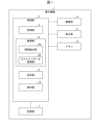
- FIG. 1 is a block diagram showing an example of the configuration of an electronic device according to Embodiment 1;
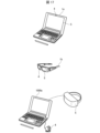
- FIG. 2 is a diagram showing the appearance of a specific configuration example of the electronic device according to Embodiment 1.
- FIG. 4 is a flowchart illustrating an example of the flow of estimating skeleton data according to the first embodiment; It is a figure which shows an example of the image data of a clenched fist. It is an example of the schematic diagram which superimposed the skeleton on the image data of the hand. It is an example of the schematic diagram which superimposed the skeleton on the image data of the hand.
- 4 is a flowchart for explaining an example of the flow of determining a cursor position based on skeleton data according to the first embodiment; It is an example of the schematic diagram which superimposed the skeleton on the image data of the hand. It is an example of the schematic diagram which superimposed the skeleton on the image data of the hand. It is an example of the schematic diagram which superimposed the skeleton on the image data of the hand. 4A and 4B are external views for explaining an example of the operation of the electronic device according to the first embodiment; FIG. It is a figure which shows an example of a change of cursor shape. 4A and 4B are external views for explaining an example of the operation of the electronic device according to the first embodiment; FIG.
- FIG. 2 is a block diagram showing an example of the configuration of an electronic device according to Embodiment 2;
- FIG. FIG. 12 is an external view for explaining an example of the operation of the electronic device according to Embodiment 3;
- FIG. 12 is a block diagram showing an example of the configuration of an electronic device according to Embodiment 4;
- 14A and 14B are diagrams showing appearances of some specific configuration examples of the electronic device according to the fourth embodiment;
- FIG. 1 is an example of a block diagram of a computer;
- the electronic device according to each embodiment refers to general devices to which electronic engineering is applied, such as smartphones, tablets, personal computers (including notebook and desktop types), smart glasses, head mounted displays, etc. It is not limited to these.
- FIG. 1 is a block diagram showing an example of the configuration of an electronic device 1 according to Embodiment 1. As shown in FIG. As an example, a case where the electronic device 1 is a smart phone will be described below, but the present embodiment is not limited to this, and can be applied to electronic devices in general.
- the electronic device 1 may be configured by a control section 2, an imaging section 4, a display section 5, a memory 6, and a storage section 7, for example.
- control unit 2 may be configured by an arithmetic device such as a microcomputer configured by a semiconductor device.
- the imaging unit 4 may have a function of acquiring imaging data (including still images and moving images) of the operator's (user's) hands.
- the imaging unit 4 is assumed to be a camera or sensor built into the electronic device 1, but an external camera or sensor may be used.
- the imaging unit 4 may be a depth camera capable of not only capturing an image (for example, an RGB image) but also measuring the distance (depth) to an object.
- Known techniques can be used for the distance measurement method, such as three-dimensional Lidar (Light Detection and Ranging), or, for example, a triangulation method using infrared light, a TOF (Time Of Flight) method, or the like.
- the imaging unit 4 may be a stereo camera having two or more imaging units.
- the imaging data acquired by the imaging unit 4 may include information indicating depth, and imaging data including information indicating depth may also be simply referred to as "imaging data".
- imaging data may be an image (for example, an RGB image) having pixel values indicating color and brightness, or an image having pixel values indicating depth (depth image).
- the memory 6 may be configured by a memory of a microcomputer integrated with the control unit 2. Also, the memory 6 may be a RAM or a ROM configured by an independent semiconductor device connected to the control unit 2 . The memory 6 may temporarily store various programs executed by the control unit 2 and various data referred to by these programs.
- the storage unit 7 may be configured by a memory of a writable semiconductor device such as a RAM or a flash memory built into the electronic device 1 . Alternatively, the storage unit 7 may be configured by an external memory connected to the electronic device 1 . The storage unit 7 may also store learning models, which will be described later.
- control unit 2 may be configured to include an acquisition unit 3 , an estimation unit 8 , a determination unit (detection unit) 9 and an operation unit (cursor display unit) 10 .
- the acquisition unit 3 may have a function of acquiring captured data of the operator's hand from the camera 4 .
- the estimation unit 8 may have a function of estimating the skeleton data corresponding to the hand of the operator based on the imaging data acquired by the acquisition unit 3 .
- skeleton data represents the shape of an object having volume by a set of line segments (skeleton) that is the skeleton of the object. It may be represented by a line segment indicating the axis or a line segment indicating the frame of the portion.
- a skeleton may differ from the actual skeleton of the object. For example, the skeleton of the hand does not necessarily have to follow the bones of the hand.
- Skeleton data may also be a set of points called a skeleton mesh obtained by sampling several representative points of the skeleton.
- An algorithm for the estimation unit 8 to estimate the skeleton data corresponding to the hand of the operator based on the imaging data acquired by the acquisition unit 3 is not particularly limited.
- Skeleton data corresponding to the operator's hand may be estimated using a learning model machine-learned using a pair of the captured image data and the skeleton data of the hand as teacher data.
- the estimation unit 8 may include an area extraction unit 8a and a skeleton data estimation unit 8b.
- the area extracting unit 8a may extract an area including the hand based on the imaging data.
- Algorithm for the region extraction unit 8a to extract a region containing a hand is not particularly limited, and a known algorithm may be used. By doing so, a region including the hand may be extracted from the imaging data.
- the term "palm" refers to a part of the hand other than the fingers.
- the region extracting unit 8a detects a palm when the operator does not hold his hand, for example, when the operator's hand is open, and detects a clenched fist when the operator holds his hand. you can The region extraction unit 8a may extract a region including the operator's hand based on the detected position and range of the clenched fist or palm.
- the skeleton data estimation unit 8b may estimate skeleton data corresponding to the hand from the area including the hand extracted by the area extraction unit 8a.
- the skeleton data estimator 8b may use the learning model as described above to estimate the skeleton data corresponding to the hand.
- the processing speed and estimation accuracy can be improved by extracting the area containing the hand and then estimating the skeleton data using the extracted area.
- the processing speed can be further improved by the area extraction unit 8a extracting an area including a hand based on the detection result of a clenched fist or a palm in the imaging data.
- the shape of the open hand is a complicated shape, and the processing time for the detection process is long. .
- the determination unit 9 may have a function of determining the cursor position for operating the electronic device 1 based on the skeleton data estimated by the estimation unit 8 . That is, the electronic device 1 may be an electronic device that can be operated by input involving coordinates, and the cursor position may be used to indicate the coordinates of the input. The determination unit 9 may also have a function of detecting an action (gesture) for operating the electronic device 1 based on the skeleton data estimated by the estimation unit 8 .
- the operation unit 10 may operate the application executed by the electronic device 1 based on the cursor position determined by the determination unit 9 . Further, the operation unit 10 may operate the application executed by the electronic device 1 based on the action (gesture) detected by the determination unit 9 .
- FIG. 2 is a diagram showing the appearance of a specific configuration example of the electronic device 1 according to the first embodiment.
- the imaging unit 4 may be a camera that captures the surface side of the electronic device 1 (the side where the electronic device 1 is shown in FIG. 2).
- the electronic device 1 also has a camera for photographing the back side (the side opposite to the electronic device 1 shown in FIG. good too. However, when using the camera on the back side, the operator's hand is blocked by the electronic device 1, making it difficult to see directly.
- the electronic device 1 may have a display section 5 (display) on the surface side. An image is displayed on the display unit 5 of the electronic device 1 , and the electronic device 1 may be operated by touching the display unit 5 with a finger or other object.
- the electronic device 1 may have a control section 2, a memory 6 and a storage section 7 therein.
- FIG. 3 is a flowchart illustrating an example of the flow of estimating skeleton data according to the first embodiment.
- FIG. 4 is a diagram showing an example of image data of the clenched fist 40 included in the imaging data detected by the area extracting unit 8a in step S32.
- the image data of the clenched fist 40 detected by the region extraction unit 8a may vary from person to person. Also, the right hand or the left hand may be selectively indicated depending on the dominant hand of the operator. FIG. 4 shows the case where the dominant hand of the operator is the right hand, but if the operator's dominant hand is the left hand, the image data of the clenched fist of the left hand may be acquired.
- Algorithms for detecting a clenched fist or a palm by the region extraction unit 8a are not particularly limited, and a known object recognition algorithm may be used.
- a clenched fist or a palm may be detected using a learning model in which pairs with regions are trained as teacher data.
- the region extracting unit 8a may extract a region containing the hand corresponding to the clenched fist or the palm (step S33). For example, in step S32, the region extracting unit 8a detects a fist or palm using a learning model that is trained using a set of image data of a fist or palm and a region of the hand corresponding to the fist or palm as teacher data. If so, the region extraction unit 8a may extract the region of the hand, which is the output of the learning model, as the region 41 including the hand corresponding to the clenched fist or the palm. Alternatively, the region extracting unit 8a may extract the region 41 including the hand corresponding to the clenched fist or the palm based on the position of the clenched fist or the palm detected in step S32.
- the region extracting unit 8a can quickly detect one or more hand regions by extracting a region containing a hand based on a clenched fist or a palm, and the skeleton data estimating unit 8b can estimate skeleton data. can do.
- the skeleton data estimation unit 8b may estimate skeleton data from the area including the hand extracted by the area extraction unit 8a (step S34).
- the skeleton data estimating unit 8b performs machine-learning using sets of imaging data of a large number of hands (including hands of various shapes such as clenched fists and open hands) and skeleton data of the hands as teacher data.
- the skeleton data corresponding to the operator's hand may be estimated from the area including the hand extracted by the area extraction unit 8a.
- the skeleton data estimating unit 8b includes a learning model for right hand recognition machine-learned using a set of imaged data of the right hand and skeleton data of the hand as teacher data, and an image data of the left hand and the skeleton of the hand.
- a learning model for left hand recognition that has been machine-learned using pairs of data as teacher data, and depending on which learning model the skeleton data was acquired, whether the operator's hand is the right hand or the left hand is recognized.
- FIG. 5 is an example of a schematic diagram in which the skeleton 51 indicated by the skeleton data determined by the skeleton data estimation unit 8b is superimposed on the image data of the hand 50 with a clenched fist. However, the superimposed skeleton 51 is added schematically, and the skeleton data should be determined in the control unit 2 .
- FIG. 6 is an example of a schematic diagram in which the skeleton 61 indicated by the skeleton data determined by the skeleton data estimation unit 8b is superimposed on the image data of the open hand 60 .
- the estimating unit 8 estimates the skeleton data, so that the control unit 2 can determine the operator's position such as the position of the operator's palm and fingers on the plane and the three-dimensional depth between the finger position and the palm position.
- the control unit 2 can determine the operator's position such as the position of the operator's palm and fingers on the plane and the three-dimensional depth between the finger position and the palm position.
- Various values can be obtained from the hands of As a result, for example, it is possible to obtain data equivalent to that obtained when the operator wears a glove-type sensor on his or her hand.
- the determining unit 9 can determine the cursor position and detect gestures (actions), and can operate the electronic device 1 or the application executed by the electronic device 1 .
- FIG. 7 is a flow chart explaining an example of the flow of determining the cursor position based on the skeleton data according to the first embodiment.
- the determination unit 9 may determine the cursor position based on the skeleton data estimated by the estimation unit 9 (step S61).
- the determination unit 9 may calculate the position of a specific part of the operator's hand based on the skeleton data and determine the cursor position so as to correspond to the position.
- the determining unit 9 may calculate the position of the base of a specific finger of the operator's hand and determine the cursor position so as to correspond to the position of the base of the specific finger.
- the determining unit 9 determines the position of the region containing the hand extracted by the region extracting unit 8a in the imaging data, and the position of the operator's hand in the entire hand at a specific part calculated based on the skeleton data. may be determined as the cursor position.
- FIG. 8 is an example of a schematic diagram in which a skeleton is superimposed on the image data of the hand 70 of the operator.
- the determination unit 9 may specify a point 72 indicating the root B of the index finger based on the skeleton data 73 and determine the cursor position so as to correspond to the position of the specified point 72 .
- the determination unit (detection unit) 9 may detect gestures (actions for operating the electronic device 1) based on the skeleton data 73 estimated by the estimation unit 9 (step S62).
- the gesture (action) detected by the determination unit 9 is not particularly limited, and various gestures (actions) may be detected. you can
- different gestures may be assigned to each form of the skeleton model.
- the form of the skeleton model is represented by specific parameters defined in the skeleton data 73 and the conditions that the parameters satisfy. For example, when a specific parameter defined in the skeleton data 73 satisfies a specific condition, the determination unit 9 may detect a gesture corresponding to the parameter and condition.
- a predetermined threshold Whether or not the relative distance is less than or equal to a predetermined threshold Whether or not the relative distance is within a predetermined range Whether or not the angle is less than or equal to a predetermined threshold Whether or not the angle is within a predetermined range , a predetermined shape (for example, whether the shape formed by the five fingers is a “pa” shape or a “goo” shape, etc.) ⁇ Whether the moving speed is equal to or less than a predetermined threshold value ⁇ Whether the moving speed is within a predetermined range ⁇ Whether the condition satisfying the above conditions has continued for a threshold value or more, etc., but are not limited to these.
- the predetermined point may be an arbitrary point in the skeleton data 73, such as an arbitrary position of an arbitrary finger, an arbitrary position of the palm, or an arbitrary position of a clenched fist.
- the gesture to be assigned may be changed depending on whether the user is right-handed or left-handed.
- the determination unit 9 may refer to Table 1 below to determine the gesture.
- Table 1 is a table showing assigned gestures for each combination of parameters and conditions. Note that one or more parameters may be used. Also, the same gesture may be assigned to multiple combinations.
- the determining unit 9 may detect gestures based on the relative distances of a plurality of predetermined points in the skeleton data 73. For example, in a hand 70 shown in FIG. A click action may be detected based on the positional relationship with 72 . Note that the fingertip does not only refer to the tip of the finger, but may be any movable part of the finger other than the tip.
- the point corresponding to the first joint of the index finger may be the point 71, and the point indicating the base B of the index finger may be the point 72.
- the point corresponding to the tip of the index finger may be the point 71 and the point corresponding to the tip of the thumb may be the point 72 .
- the gesture may be detected based on the positional relationship of three points corresponding to the tip of the index finger, the tip of the middle finger, and the tip of the thumb. In this way, any points in the skeleton data 73 can be used as points used for gesture detection.
- the operator may form a hand such as hand 80 shown in FIG. 9, then form a hand such as hand 90 shown in FIG.
- a click action may be performed by reverting to shape.
- the determining unit 9 may specify a point 81 indicating the tip A of the index finger and a point 82 indicating the root B of the index finger based on the skeleton data 83 for the hand 80 . Further, the determination unit 9 may specify a point 91 indicating the tip A of the index finger and a point 92 indicating the root B of the index finger for the hand 90 based on the skeleton data 93 .
- the base 82 of the index finger set in step S63 since the base 82 of the index finger set in step S63 is covered by the thumb, it need not be recognized from the image of the operator's hand. However, as for information on the operator's hand 80, the skeleton and/or the virtual glove model are recognized by the recognition of the operator's hand shown in FIG. It's okay.
- the position A of the tip 81 of the index finger set in step S62 in FIG. 8 and the position B of the root 82 of the index finger set in step S63 are positioned apart from each other, as in the state in which the operator's hand 80 is open. good.
- the tip 81 of the index finger set in step S62 can be recognized from the image of the operator's hand acquired from the camera 4, and the base 82 of the index finger set in step S63 can be recognized by the operation acquired from the camera 4. He explained that it is okay not to be able to recognize from the image of the person's hand. However, both the tip 81 of the index finger set in step S62 and the root 82 of the index finger set in step S63 may not be recognizable from the image of the operator's hand acquired from the camera 4. This may be because the information of the operator's hand 80 is recognized as a skeleton and/or a virtual glove model by recognition of the operator's hand shown in FIG. 3, as described above.
- the determining unit 9 detects that the distance between the points 91 and 92 on the hand 90 is narrower than the distance between the points 81 and 82 on the hand 80, and then detects It may be determined that the click action has been performed when it is detected that the distance between the point 81 and the point 82 is reached.
- the determination unit 9 may determine that a click action has been performed when the index finger and the middle finger are both extended and the index finger and the middle finger are in contact and then separated. The determination unit 9 may determine whether or not each finger is in an extended state, for example, based on whether or not the tips, bases, and joint points of the fingers are aligned. Further, the finger to be judged is not limited to the index finger and the middle finger.
- the determination unit 9 can detect a gesture based on the positional relationship between the fingertip point of a specific finger and the base point of the finger. Specifically, for example, the determination unit 9 can detect a click action based on the positional relationship between the tip point of the index finger and the base point of the finger. According to this, since the root portion of the finger, which is the fulcrum of the motion, moves less, the present invention according to the embodiment can easily detect the gesture. That is, according to the present invention according to one embodiment, operational stability can be improved.
- the operator changes the shape of the hand into the shape of the hand indicating the start of the gesture, moves the hand, and then changes the shape of the hand to the shape of the hand indicating the end of the gesture.
- Gestures can be made that specify movement, such as drag-and-drop actions.
- the operator makes a hand shape like the hand 80 shown in FIG. 9, then makes the hand shape like the hand 90 shown in FIG.
- a swipe action may be performed by reverting to the hand shape.
- the determination unit 9 detects that the distance between the points 91 and 92 on the hand 90 is smaller than the distance between the points 81 and 82 on the hand 80, and then the point 91 It may be determined that a swipe action has been performed when it detects that the has moved and then spreads to the distance between points 81 and 82 on the hand 80 .
- the operator's hand 90 in FIG. 10 is a very complicated hand because the fingers other than the index finger are clenched (bent) and the index finger is overlapped and bent. has the shape of In particular, the base of the index finger is hidden by other fingers.
- the determining unit 9 can detect each point including the base of the index finger based on the skeleton data.
- FIG. 11 is an external view for explaining an example of the operation of the electronic device 1.
- the electronic device 1 may specifically be a smart phone.
- the electronic device 1 may include a camera 104 and a display section 105 .
- the acquisition unit 3 may set the monitor area 106 on the display unit 105 and display the captured image captured by the camera 104 in the monitor area 106 .
- the monitor area 106 displays the operator's hand captured by the camera 104, and may be displayed in the upper left corner of the screen so as not to hide the screen of the operation target. Also, this monitor area 106 may not be provided.
- the operation unit (cursor display unit) 10 may display a cursor 107 on the display unit (display screen) 105 at a position corresponding to the cursor position determined by the determination unit 9 . That is, the cursor 107 may move up and down, left and right, according to the movement of the operator's hand within the range captured by the camera 104 .
- the operation unit 10 may display an icon for executing an application executable by the electronic device 1 in the icon area 108 of the display unit 105 . Then, when the determination unit 9 detects a click action while the cursor 107 overlaps the icon in the icon area 108, the operation unit 10 may execute the application corresponding to the icon.
- the operation unit 10 moves the cursor position and detects the detected action.
- the application may be operated.
- the shape and color of the cursor 107 displayed on the display unit 105 by the operation unit 10 are not particularly limited. good.
- the operation unit 10 displays the cursor 107 in blue
- the determination unit 9 detects a click action and a swipe action
- the operation unit 10 displays the cursor 107 may be displayed in green
- the determination unit 9 detects a drag-and-drop action
- the operation unit 10 may change the color of the cursor 107, such as displaying the cursor 107 in red.
- the operation unit 10 may change the shape of the cursor according to the action detected by the determination unit 9.
- FIG. 12 is a diagram showing an example of changes in cursor shape. For example, when the determination unit 9 detects no action, the operation unit 10 displays the cursor 107a, and when the determination unit 9 detects a click action, the operation unit 10 displays an animation such as the cursor 107b. When the determination unit 9 detects a swipe action, the operation unit 10 may change the shape of the cursor, such as displaying a cursor 107c.
- part of the display unit 105 may be the system area (specific area) 109 .
- a system area 109 is an area in which a UI for system operation (for example, a home button, a return button, an option button, etc.) is displayed, and the display cannot be changed by the operation unit 10 .
- FIG. 13 is an external view showing an example of the display section 105 when the cursor position determined by the determining section 9 is within the system area 109.
- the operation unit 10 cannot display the cursor within the system area 109 .
- the operation unit 10 may display the cursor 107 d outside the system area 109 in a display mode different from the cursor 107 displayed when the cursor is positioned outside the system area 109 .
- the cursor 107d may have a different shape from the cursor 107 and may have a different color.
- the determination unit 9 detects a click action in this state
- the operation unit 10 may execute processing when a click action is performed at the cursor position within the system area 109 .
- the UI for system operation can also be successfully operated.
- the operator moves the hand and/or performs gestures with the hand within the imaging range of the camera 104 of the electronic device 1, thereby pointing the electronic device 1 without touching the electronic device 1. It can be operated like a device.
- Embodiment 2 ⁇ Configuration example> A configuration example of the second embodiment will be described below with reference to the drawings.
- the configuration of the electronic device according to Embodiment 2 is the same as the configuration of Embodiment 1 shown in FIG.
- FIG. 14 is a block diagram showing an example of the configuration of the electronic device 1 according to the second embodiment.
- the present embodiment differs from the first embodiment in that the operation unit 10 includes a determination unit 9 . That is, in this embodiment, the operation unit 10 may operate the application executed by the electronic device 1 based on the skeleton data 73 estimated by the estimation unit 8 .
- the determination unit 9 does not necessarily have to determine the cursor position, and may detect only the gesture based on the skeleton data 73. Then, the operation unit 10 and the determination unit 9 may operate the application based on the gesture. This makes it possible to operate an application that does not require a cursor position for operation.
- Embodiment 3 ⁇ Configuration example> A configuration example of the third embodiment will be described below with reference to the drawings. Unless otherwise specified, the configuration of the electronic device according to Embodiment 3 is the same as that of Embodiment 1 shown in FIG.
- FIG. 15 is an external view of the electronic device 141 for explaining the operation of the electronic device by gestures with both hands.
- Electronic device 141 may include camera 144 and display 145 .
- the display section 145 may be provided with a monitor area 146 and an icon area 149 .
- the operation unit 10 may cause the display unit 145 to display a cursor 147 .
- the determination unit 9 may detect gestures (actions) made by the operator with both hands. For example, when the operator makes the index finger and thumb L-shaped and combines the tips of the index fingers and the thumbs of both hands to form a rectangle, the decision unit 9 detects the first special action. good too. When the determination unit 9 detects the first special action, the operation unit 10 changes the shape of the cursor to a rectangular cursor 147A, and displays the property of the item displayed under the cursor 147A on the display unit 105. You may let gestures (actions) made by the operator with both hands. For example, when the operator makes the index finger and thumb L-shaped and combines the tips of the index fingers and the thumbs of both hands to form a rectangle, the decision unit 9 detects the first special action. good too. When the determination unit 9 detects the first special action, the operation unit 10 changes the shape of the cursor to a rectangular cursor 147A, and displays the property of the item displayed under the cursor 147A on the display unit 105. You may let
- the determination unit 9 may detect the second special action.
- the operation unit 10 changes the shape of the cursor to a cross mark cursor 147B, and moves the item displayed under the cursor 147B to the trash box. good.
- the determination unit 9 may detect all gestures of the operator's left hand, right hand, and both hands. Thereby, the electronic device 141 can be operated using all gestures that can be made by human hands.
- the area extracting unit 8a extracts an area including a hand corresponding to a clenched fist or a palm detected in the imaging data, thereby detecting an area including a plurality of hands at the same time. can be done.
- the operator can operate the electronic device 141 without touching the electronic device 141 by moving the hand and/or making hand gestures within the imaging range of the camera 104 of the electronic device 141. you can
- Embodiment 4 ⁇ Configuration example> A configuration example of the fourth embodiment will be described below with reference to the drawings. Unless otherwise specified, the configuration of the electronic device according to Embodiment 4 is the same as that of Embodiment 1 shown in FIG.
- FIG. 16 is a block diagram showing an example of the configuration of the electronic device 1000 according to the fourth embodiment.
- the electronic device 1000 does not include the imaging unit 4 and the display unit 5 and is connected to the imaging unit 4 and the display unit 5 outside.
- the electronic device may not necessarily include the imaging unit 4 and the display unit 5, and may have a configuration in which at least one of the imaging unit 4 and the display unit 5 exists outside.
- FIG. 17A and 17B are diagrams showing appearances of some specific configuration examples of the electronic device according to the fourth embodiment.
- the electronic device 1a is a notebook computer, and may include a camera (imaging unit 4) and a display (display unit 5).
- the electronic device 1b is smart glasses, and may include a camera (imaging unit 4) and a display or a retinal projection unit (display unit 5).
- An external head-mounted display (display unit 5) and camera (imaging unit 4) may be wirelessly or wiredly connected to the electronic device 1000a.
- an icon can be displayed, for example, in the lower right corner of the display section of the electronic device.
- the shape of this icon may be a human shape, but is not limited to this.
- Some or all of the functions of the electronic devices 1, 141, and 1000 may be implemented by hardware such as integrated circuits (IC chips), or may be implemented by software.
- the electronic devices 1, 141 and 1000 may be implemented by, for example, a computer that executes instructions of a program, which is software that implements each function.
- FIG. 15 is an example of a block diagram of this computer.
- the computer 150 may include a CPU (Central Processing Unit) 151 and a memory 152 .
- a program 153 for operating the computer 150 as the electronic devices 1 , 141 and 1000 may be recorded in the memory 152 .
- the CPU 151 may implement each function of the electronic devices 1 , 21 , 101 and 141 by reading the program 153 from the memory 152 and executing it.
- the CPU 151 may use a GPU (Graphic Processing Unit), a DSP (Digital Signal Processor), an MPU (Micro Processing Unit), an FPU (Floating point number Processing Unit), a PPU (Physics Processing Unit), or a microcontroller.
- the memory 152 may be, for example, RAM (Random Access Memory), ROM (Read Only Memory), flash memory, HDD (Hard Disk Drive), SSD (Solid State Drive), or a combination thereof.
- the computer 150 may further include a communication interface for sending and receiving data to and from other devices.
- the computer 150 may further include an input/output interface for connecting input/output devices such as a keyboard, mouse, display, and printer.
- the program 153 may be recorded in a non-transitory tangible recording medium 154 readable by the computer 150 .
- the recording medium 154 for example, a tape, disk, card, semiconductor memory, programmable logic circuit, or the like may be used.
- Computer 150 may read program 153 from recording medium 154 .
- Computer 150 may read program 153 via a transmission medium.
- a transmission medium for example, a communication network or broadcast waves may be used.
- Appendix 1 an electronic device, an acquisition unit that acquires imaging data of an operator's hand; an estimation unit that estimates skeleton data corresponding to the hand based on the imaging data; a determination unit that determines a cursor position for operating the electronic device based on the skeleton data; electronic equipment.
- Appendix 2 an electronic device, an acquisition unit that acquires imaging data of an operator's hand; an estimation unit that estimates skeleton data corresponding to the hand based on the imaging data; an operation unit that operates an application executed by the electronic device based on the skeleton data; electronic equipment.
- (Appendix 3) at least one processor included in the electronic device, Acquisition processing for acquiring imaging data of an operator's hand; an estimation process for estimating skeleton data corresponding to the hand based on the imaging data; a determination process of determining a cursor position for operating the electronic device based on the skeleton data; A program to run the
- (Appendix 4) at least one processor included in the electronic device, Acquisition processing for acquiring imaging data of an operator's hand; an estimation process for estimating skeleton data corresponding to the hand based on the imaging data; an operation process for operating an application executed by the electronic device based on the skeleton data; A program to run the
- the present invention is not limited to the above-described embodiments, but can be modified in various ways within the scope of the claims, and can be obtained by appropriately combining technical means disclosed in different embodiments. is also included in the technical scope of the present invention.
- a new technical feature can be formed by combining the technical means disclosed in each embodiment.
Landscapes
- Engineering & Computer Science (AREA)
- Theoretical Computer Science (AREA)
- General Engineering & Computer Science (AREA)
- Human Computer Interaction (AREA)
- General Physics & Mathematics (AREA)
- Physics & Mathematics (AREA)
- Multimedia (AREA)
- Social Psychology (AREA)
- Psychiatry (AREA)
- Health & Medical Sciences (AREA)
- General Health & Medical Sciences (AREA)
- Computer Vision & Pattern Recognition (AREA)
- User Interface Of Digital Computer (AREA)
- Position Input By Displaying (AREA)
- Image Analysis (AREA)
Priority Applications (9)
| Application Number | Priority Date | Filing Date | Title |
|---|---|---|---|
| CN202180005525.2A CN116075801A (zh) | 2021-08-30 | 2021-08-30 | 电子设备及程序 |
| US17/764,151 US20230061557A1 (en) | 2021-08-30 | 2021-08-30 | Electronic device and program |
| PCT/JP2021/031679 WO2023031988A1 (ja) | 2021-08-30 | 2021-08-30 | 電子機器及びプログラム |
| KR1020257000168A KR20250005559A (ko) | 2021-08-30 | 2021-08-30 | 전자기기 및 프로그램 |
| CA3229530A CA3229530A1 (en) | 2021-08-30 | 2021-08-30 | Electronic apparatus and program |
| JP2022517908A JP7213396B1 (ja) | 2021-08-30 | 2021-08-30 | 電子機器及びプログラム |
| KR1020227009845A KR20230035209A (ko) | 2021-08-30 | 2021-08-30 | 전자기기 및 프로그램 |
| EP21955885.5A EP4398072A4 (en) | 2021-08-30 | 2021-08-30 | ELECTRONIC DEVICE AND PROGRAM |
| AU2021463303A AU2021463303B2 (en) | 2021-08-30 | 2021-08-30 | Electronic apparatus and program |
Applications Claiming Priority (1)
| Application Number | Priority Date | Filing Date | Title |
|---|---|---|---|
| PCT/JP2021/031679 WO2023031988A1 (ja) | 2021-08-30 | 2021-08-30 | 電子機器及びプログラム |
Publications (1)
| Publication Number | Publication Date |
|---|---|
| WO2023031988A1 true WO2023031988A1 (ja) | 2023-03-09 |
Family
ID=85035377
Family Applications (1)
| Application Number | Title | Priority Date | Filing Date |
|---|---|---|---|
| PCT/JP2021/031679 Ceased WO2023031988A1 (ja) | 2021-08-30 | 2021-08-30 | 電子機器及びプログラム |
Country Status (8)
| Country | Link |
|---|---|
| US (1) | US20230061557A1 (https=) |
| EP (1) | EP4398072A4 (https=) |
| JP (1) | JP7213396B1 (https=) |
| KR (2) | KR20230035209A (https=) |
| CN (1) | CN116075801A (https=) |
| AU (1) | AU2021463303B2 (https=) |
| CA (1) | CA3229530A1 (https=) |
| WO (1) | WO2023031988A1 (https=) |
Families Citing this family (4)
| Publication number | Priority date | Publication date | Assignee | Title |
|---|---|---|---|---|
| KR20240107515A (ko) * | 2022-12-30 | 2024-07-09 | 현대자동차주식회사 | 사용자 인터페이스 장치 및 방법, 이를 포함하는 차량 |
| WO2025088912A1 (ja) * | 2023-10-23 | 2025-05-01 | ソニーグループ株式会社 | 情報処理装置、情報処理方法、及びプログラム |
| JP7657998B1 (ja) | 2024-03-14 | 2025-04-07 | ソフトバンク株式会社 | 電子機器、プログラム、及び制御方法 |
| JP7733158B1 (ja) * | 2024-03-14 | 2025-09-02 | ソフトバンク株式会社 | 電子機器、プログラム、及び制御方法 |
Citations (3)
| Publication number | Priority date | Publication date | Assignee | Title |
|---|---|---|---|---|
| JPH05324181A (ja) * | 1992-05-26 | 1993-12-07 | Takenaka Komuten Co Ltd | ハンドポインティング式入力装置 |
| JP2013171529A (ja) | 2012-02-22 | 2013-09-02 | Shimane Prefecture | 操作入力装置、操作判定方法およびプログラム |
| WO2014010670A1 (ja) * | 2012-07-13 | 2014-01-16 | Isayama Taro | 要素選択装置、要素選択方法、および、プログラム |
Family Cites Families (42)
| Publication number | Priority date | Publication date | Assignee | Title |
|---|---|---|---|---|
| US8005263B2 (en) * | 2007-10-26 | 2011-08-23 | Honda Motor Co., Ltd. | Hand sign recognition using label assignment |
| US8881049B2 (en) * | 2007-12-14 | 2014-11-04 | Apple Inc. | Scrolling displayed objects using a 3D remote controller in a media system |
| US8514251B2 (en) * | 2008-06-23 | 2013-08-20 | Qualcomm Incorporated | Enhanced character input using recognized gestures |
| US8379987B2 (en) * | 2008-12-30 | 2013-02-19 | Nokia Corporation | Method, apparatus and computer program product for providing hand segmentation for gesture analysis |
| JP2010181978A (ja) * | 2009-02-03 | 2010-08-19 | Seiko Epson Corp | 共同作業装置及び共同作業の制御方法 |
| JP2011028366A (ja) * | 2009-07-22 | 2011-02-10 | Sony Corp | 操作制御装置および操作制御方法 |
| US20170017393A1 (en) * | 2010-04-23 | 2017-01-19 | Handscape Inc., A Delaware Corporation | Method for controlling interactive objects from a touchpad of a computerized device |
| US9891820B2 (en) * | 2010-04-23 | 2018-02-13 | Handscape Inc. | Method for controlling a virtual keyboard from a touchpad of a computerized device |
| WO2011142317A1 (ja) * | 2010-05-11 | 2011-11-17 | 日本システムウエア株式会社 | ジェスチャー認識装置、方法、プログラム、および該プログラムを格納したコンピュータ可読媒体 |
| JP5656514B2 (ja) * | 2010-08-27 | 2015-01-21 | キヤノン株式会社 | 情報処理装置及び方法 |
| US8768006B2 (en) * | 2010-10-19 | 2014-07-01 | Hewlett-Packard Development Company, L.P. | Hand gesture recognition |
| US8994718B2 (en) * | 2010-12-21 | 2015-03-31 | Microsoft Technology Licensing, Llc | Skeletal control of three-dimensional virtual world |
| US8897491B2 (en) * | 2011-06-06 | 2014-11-25 | Microsoft Corporation | System for finger recognition and tracking |
| US9030498B2 (en) * | 2011-08-15 | 2015-05-12 | Apple Inc. | Combining explicit select gestures and timeclick in a non-tactile three dimensional user interface |
| WO2013135299A1 (en) * | 2012-03-15 | 2013-09-19 | Cherradi El Fadili Ibrahim Farid | Extending the free fingers typing technology and introducing the finger taps language technology |
| US9671874B2 (en) * | 2012-11-08 | 2017-06-06 | Cuesta Technology Holdings, Llc | Systems and methods for extensions to alternative control of touch-based devices |
| WO2014128749A1 (ja) * | 2013-02-19 | 2014-08-28 | 株式会社ブリリアントサービス | 形状認識装置、形状認識プログラム、および形状認識方法 |
| JP6095478B2 (ja) * | 2013-05-16 | 2017-03-15 | スタンレー電気株式会社 | 入力操作装置 |
| US9383894B2 (en) * | 2014-01-08 | 2016-07-05 | Microsoft Technology Licensing, Llc | Visual feedback for level of gesture completion |
| WO2015108112A1 (ja) * | 2014-01-15 | 2015-07-23 | 株式会社Juice Design | 操作判定装置、操作判定方法、および、プログラム |
| RU2014108820A (ru) * | 2014-03-06 | 2015-09-20 | ЭлЭсАй Корпорейшн | Процессор изображений, содержащий систему распознавания жестов с функциональными возможностями обнаружения и отслеживания пальцев |
| US9990046B2 (en) * | 2014-03-17 | 2018-06-05 | Oblong Industries, Inc. | Visual collaboration interface |
| US9589203B2 (en) * | 2014-03-24 | 2017-03-07 | Tata Consultancy Services Limited | Action based activity determination system and method |
| US10852838B2 (en) * | 2014-06-14 | 2020-12-01 | Magic Leap, Inc. | Methods and systems for creating virtual and augmented reality |
| US9804696B2 (en) * | 2015-01-02 | 2017-10-31 | Microsoft Technology Licensing, Llc | User-input control device toggled motion tracking |
| EP3210098A1 (en) * | 2015-01-28 | 2017-08-30 | Huawei Technologies Co., Ltd. | Hand or finger detection device and a method thereof |
| ES2929648T3 (es) * | 2015-04-30 | 2022-11-30 | Sony Group Corp | Dispositivo de procesamiento de imágenes, método de procesamiento de imágenes y programa |
| US10409443B2 (en) * | 2015-06-24 | 2019-09-10 | Microsoft Technology Licensing, Llc | Contextual cursor display based on hand tracking |
| US10372228B2 (en) * | 2016-07-20 | 2019-08-06 | Usens, Inc. | Method and system for 3D hand skeleton tracking |
| US11263409B2 (en) * | 2017-11-03 | 2022-03-01 | Board Of Trustees Of Michigan State University | System and apparatus for non-intrusive word and sentence level sign language translation |
| US10296102B1 (en) * | 2018-01-31 | 2019-05-21 | Piccolo Labs Inc. | Gesture and motion recognition using skeleton tracking |
| US11573641B2 (en) * | 2018-03-13 | 2023-02-07 | Magic Leap, Inc. | Gesture recognition system and method of using same |
| US11009941B2 (en) * | 2018-07-25 | 2021-05-18 | Finch Technologies Ltd. | Calibration of measurement units in alignment with a skeleton model to control a computer system |
| US10902250B2 (en) * | 2018-12-21 | 2021-01-26 | Microsoft Technology Licensing, Llc | Mode-changeable augmented reality interface |
| US11294472B2 (en) * | 2019-01-11 | 2022-04-05 | Microsoft Technology Licensing, Llc | Augmented two-stage hand gesture input |
| US10984575B2 (en) * | 2019-02-06 | 2021-04-20 | Snap Inc. | Body pose estimation |
| CN110443154B (zh) * | 2019-07-15 | 2022-06-03 | 北京达佳互联信息技术有限公司 | 关键点的三维坐标定位方法、装置、电子设备和存储介质 |
| US11182909B2 (en) * | 2019-12-10 | 2021-11-23 | Google Llc | Scalable real-time hand tracking |
| US12343616B2 (en) * | 2020-03-09 | 2025-07-01 | Disney Enterprises, Inc. | Interactive entertainment system |
| US11954242B2 (en) * | 2021-01-04 | 2024-04-09 | Apple Inc. | Devices, methods, and graphical user interfaces for interacting with three-dimensional environments |
| EP4295218A1 (en) * | 2021-03-22 | 2023-12-27 | Apple Inc. | Methods for manipulating objects in an environment |
| US12279882B2 (en) * | 2021-07-23 | 2025-04-22 | Google Llc | Movement disorder diagnostics from video data using body landmark tracking |
-
2021
- 2021-08-30 EP EP21955885.5A patent/EP4398072A4/en active Pending
- 2021-08-30 CA CA3229530A patent/CA3229530A1/en active Pending
- 2021-08-30 CN CN202180005525.2A patent/CN116075801A/zh active Pending
- 2021-08-30 US US17/764,151 patent/US20230061557A1/en active Pending
- 2021-08-30 AU AU2021463303A patent/AU2021463303B2/en active Active
- 2021-08-30 KR KR1020227009845A patent/KR20230035209A/ko not_active Ceased
- 2021-08-30 JP JP2022517908A patent/JP7213396B1/ja active Active
- 2021-08-30 KR KR1020257000168A patent/KR20250005559A/ko active Pending
- 2021-08-30 WO PCT/JP2021/031679 patent/WO2023031988A1/ja not_active Ceased
Patent Citations (3)
| Publication number | Priority date | Publication date | Assignee | Title |
|---|---|---|---|---|
| JPH05324181A (ja) * | 1992-05-26 | 1993-12-07 | Takenaka Komuten Co Ltd | ハンドポインティング式入力装置 |
| JP2013171529A (ja) | 2012-02-22 | 2013-09-02 | Shimane Prefecture | 操作入力装置、操作判定方法およびプログラム |
| WO2014010670A1 (ja) * | 2012-07-13 | 2014-01-16 | Isayama Taro | 要素選択装置、要素選択方法、および、プログラム |
Non-Patent Citations (1)
| Title |
|---|
| See also references of EP4398072A4 |
Also Published As
| Publication number | Publication date |
|---|---|
| KR20230035209A (ko) | 2023-03-13 |
| US20230061557A1 (en) | 2023-03-02 |
| AU2021463303A1 (en) | 2024-03-07 |
| JP7213396B1 (ja) | 2023-01-26 |
| EP4398072A4 (en) | 2025-01-29 |
| CN116075801A (zh) | 2023-05-05 |
| EP4398072A1 (en) | 2024-07-10 |
| KR20250005559A (ko) | 2025-01-09 |
| CA3229530A1 (en) | 2023-03-09 |
| JPWO2023031988A1 (https=) | 2023-03-09 |
| AU2021463303B2 (en) | 2026-02-05 |
Similar Documents
| Publication | Publication Date | Title |
|---|---|---|
| JP7213396B1 (ja) | 電子機器及びプログラム | |
| US11048333B2 (en) | System and method for close-range movement tracking | |
| US8290210B2 (en) | Method and system for gesture recognition | |
| US9910498B2 (en) | System and method for close-range movement tracking | |
| JPWO2023031988A5 (https=) | ||
| US9317130B2 (en) | Visual feedback by identifying anatomical features of a hand | |
| JP6165485B2 (ja) | 携帯端末向けarジェスチャユーザインタフェースシステム | |
| KR20140140095A (ko) | 증강된 가상 터치패드 및 터치스크린 | |
| US20160320846A1 (en) | Method for providing user commands to an electronic processor and related processor program and electronic circuit | |
| CN105046249B (zh) | 一种人机交互方法 | |
| JPWO2015030264A1 (ja) | クリック動作検出装置,方法およびプログラム | |
| JP2024520943A (ja) | キー機能実行方法、キー機能実行システム、キー機能実行装置、電子機器、及びコンピュータプログラム | |
| JP2025104251A (ja) | 実物感のあるタイピング又はタッチの実現方法 | |
| Roy et al. | Real time hand gesture based user friendly human computer interaction system | |
| CN104851134A (zh) | 虚拟触发与真实物体触发相结合的扩增实境系统及其方法 | |
| Hartanto et al. | Real time hand gesture movements tracking and recognizing system | |
| CN107797748A (zh) | 虚拟键盘输入方法和装置及机器人 | |
| JP2015122124A (ja) | 仮想マウスによるデータ入力機能を有する情報装置 | |
| Shajideen et al. | Human-computer interaction system using 2D and 3D hand gestures | |
| CN106791775A (zh) | 一种图像处理方法和移动终端 | |
| TW201925989A (zh) | 互動系統 | |
| JP6523509B1 (ja) | ゲームプログラム、方法、および情報処理装置 | |
| Dave et al. | Project Mudra: Personalization of Computers using Natural Interface | |
| Pullan et al. | High Resolution Touch Screen Module | |
| KR20250007373A (ko) | 모션 인식 장치 및 방법 |
Legal Events
| Date | Code | Title | Description |
|---|---|---|---|
| ENP | Entry into the national phase |
Ref document number: 2022517908 Country of ref document: JP Kind code of ref document: A |
|
| 121 | Ep: the epo has been informed by wipo that ep was designated in this application |
Ref document number: 21955885 Country of ref document: EP Kind code of ref document: A1 |
|
| WWE | Wipo information: entry into national phase |
Ref document number: 2021463303 Country of ref document: AU Ref document number: 3229530 Country of ref document: CA Ref document number: 808435 Country of ref document: NZ Ref document number: AU2021463303 Country of ref document: AU |
|
| ENP | Entry into the national phase |
Ref document number: 2021463303 Country of ref document: AU Date of ref document: 20210830 Kind code of ref document: A |
|
| WWE | Wipo information: entry into national phase |
Ref document number: 11202401080Q Country of ref document: SG |
|
| WWE | Wipo information: entry into national phase |
Ref document number: 2021955885 Country of ref document: EP |
|
| NENP | Non-entry into the national phase |
Ref country code: DE |
|
| ENP | Entry into the national phase |
Ref document number: 2021955885 Country of ref document: EP Effective date: 20240402 |