WO2023026819A1 - 高強度鋼板およびその製造方法 - Google Patents
高強度鋼板およびその製造方法 Download PDFInfo
- Publication number
- WO2023026819A1 WO2023026819A1 PCT/JP2022/030044 JP2022030044W WO2023026819A1 WO 2023026819 A1 WO2023026819 A1 WO 2023026819A1 JP 2022030044 W JP2022030044 W JP 2022030044W WO 2023026819 A1 WO2023026819 A1 WO 2023026819A1
- Authority
- WO
- WIPO (PCT)
- Prior art keywords
- less
- steel sheet
- layer
- cold
- martensite
- Prior art date
- Legal status (The legal status is an assumption and is not a legal conclusion. Google has not performed a legal analysis and makes no representation as to the accuracy of the status listed.)
- Ceased
Links
Images



Classifications
-
- C—CHEMISTRY; METALLURGY
- C21—METALLURGY OF IRON
- C21D—MODIFYING THE PHYSICAL STRUCTURE OF FERROUS METALS; GENERAL DEVICES FOR HEAT TREATMENT OF FERROUS OR NON-FERROUS METALS OR ALLOYS; MAKING METAL MALLEABLE, e.g. BY DECARBURISATION OR TEMPERING
- C21D9/00—Heat treatment, e.g. annealing, hardening, quenching or tempering, adapted for particular articles; Furnaces therefor
- C21D9/46—Heat treatment, e.g. annealing, hardening, quenching or tempering, adapted for particular articles; Furnaces therefor for sheet metals
-
- B—PERFORMING OPERATIONS; TRANSPORTING
- B32—LAYERED PRODUCTS
- B32B—LAYERED PRODUCTS, i.e. PRODUCTS BUILT-UP OF STRATA OF FLAT OR NON-FLAT, e.g. CELLULAR OR HONEYCOMB, FORM
- B32B15/00—Layered products comprising a layer of metal
- B32B15/01—Layered products comprising a layer of metal all layers being exclusively metallic
- B32B15/012—Layered products comprising a layer of metal all layers being exclusively metallic one layer being formed of an iron alloy or steel, another layer being formed of aluminium or an aluminium alloy
-
- B—PERFORMING OPERATIONS; TRANSPORTING
- B32—LAYERED PRODUCTS
- B32B—LAYERED PRODUCTS, i.e. PRODUCTS BUILT-UP OF STRATA OF FLAT OR NON-FLAT, e.g. CELLULAR OR HONEYCOMB, FORM
- B32B15/00—Layered products comprising a layer of metal
- B32B15/01—Layered products comprising a layer of metal all layers being exclusively metallic
- B32B15/013—Layered products comprising a layer of metal all layers being exclusively metallic one layer being formed of an iron alloy or steel, another layer being formed of a metal other than iron or aluminium
-
- C—CHEMISTRY; METALLURGY
- C21—METALLURGY OF IRON
- C21D—MODIFYING THE PHYSICAL STRUCTURE OF FERROUS METALS; GENERAL DEVICES FOR HEAT TREATMENT OF FERROUS OR NON-FERROUS METALS OR ALLOYS; MAKING METAL MALLEABLE, e.g. BY DECARBURISATION OR TEMPERING
- C21D6/00—Heat treatment of ferrous alloys
- C21D6/004—Heat treatment of ferrous alloys containing Cr and Ni
-
- C—CHEMISTRY; METALLURGY
- C21—METALLURGY OF IRON
- C21D—MODIFYING THE PHYSICAL STRUCTURE OF FERROUS METALS; GENERAL DEVICES FOR HEAT TREATMENT OF FERROUS OR NON-FERROUS METALS OR ALLOYS; MAKING METAL MALLEABLE, e.g. BY DECARBURISATION OR TEMPERING
- C21D6/00—Heat treatment of ferrous alloys
- C21D6/005—Heat treatment of ferrous alloys containing Mn
-
- C—CHEMISTRY; METALLURGY
- C21—METALLURGY OF IRON
- C21D—MODIFYING THE PHYSICAL STRUCTURE OF FERROUS METALS; GENERAL DEVICES FOR HEAT TREATMENT OF FERROUS OR NON-FERROUS METALS OR ALLOYS; MAKING METAL MALLEABLE, e.g. BY DECARBURISATION OR TEMPERING
- C21D6/00—Heat treatment of ferrous alloys
- C21D6/008—Heat treatment of ferrous alloys containing Si
-
- C—CHEMISTRY; METALLURGY
- C21—METALLURGY OF IRON
- C21D—MODIFYING THE PHYSICAL STRUCTURE OF FERROUS METALS; GENERAL DEVICES FOR HEAT TREATMENT OF FERROUS OR NON-FERROUS METALS OR ALLOYS; MAKING METAL MALLEABLE, e.g. BY DECARBURISATION OR TEMPERING
- C21D8/00—Modifying the physical properties of ferrous metals or ferrous alloys by deformation combined with, or followed by, heat treatment
- C21D8/02—Modifying the physical properties of ferrous metals or ferrous alloys by deformation combined with, or followed by, heat treatment during manufacturing of plates or strips
-
- C—CHEMISTRY; METALLURGY
- C21—METALLURGY OF IRON
- C21D—MODIFYING THE PHYSICAL STRUCTURE OF FERROUS METALS; GENERAL DEVICES FOR HEAT TREATMENT OF FERROUS OR NON-FERROUS METALS OR ALLOYS; MAKING METAL MALLEABLE, e.g. BY DECARBURISATION OR TEMPERING
- C21D8/00—Modifying the physical properties of ferrous metals or ferrous alloys by deformation combined with, or followed by, heat treatment
- C21D8/02—Modifying the physical properties of ferrous metals or ferrous alloys by deformation combined with, or followed by, heat treatment during manufacturing of plates or strips
- C21D8/0221—Modifying the physical properties of ferrous metals or ferrous alloys by deformation combined with, or followed by, heat treatment during manufacturing of plates or strips characterised by the working steps
- C21D8/0226—Hot rolling
-
- C—CHEMISTRY; METALLURGY
- C21—METALLURGY OF IRON
- C21D—MODIFYING THE PHYSICAL STRUCTURE OF FERROUS METALS; GENERAL DEVICES FOR HEAT TREATMENT OF FERROUS OR NON-FERROUS METALS OR ALLOYS; MAKING METAL MALLEABLE, e.g. BY DECARBURISATION OR TEMPERING
- C21D8/00—Modifying the physical properties of ferrous metals or ferrous alloys by deformation combined with, or followed by, heat treatment
- C21D8/02—Modifying the physical properties of ferrous metals or ferrous alloys by deformation combined with, or followed by, heat treatment during manufacturing of plates or strips
- C21D8/0221—Modifying the physical properties of ferrous metals or ferrous alloys by deformation combined with, or followed by, heat treatment during manufacturing of plates or strips characterised by the working steps
- C21D8/0236—Cold rolling
-
- C—CHEMISTRY; METALLURGY
- C21—METALLURGY OF IRON
- C21D—MODIFYING THE PHYSICAL STRUCTURE OF FERROUS METALS; GENERAL DEVICES FOR HEAT TREATMENT OF FERROUS OR NON-FERROUS METALS OR ALLOYS; MAKING METAL MALLEABLE, e.g. BY DECARBURISATION OR TEMPERING
- C21D8/00—Modifying the physical properties of ferrous metals or ferrous alloys by deformation combined with, or followed by, heat treatment
- C21D8/02—Modifying the physical properties of ferrous metals or ferrous alloys by deformation combined with, or followed by, heat treatment during manufacturing of plates or strips
- C21D8/0247—Modifying the physical properties of ferrous metals or ferrous alloys by deformation combined with, or followed by, heat treatment during manufacturing of plates or strips characterised by the heat treatment
- C21D8/0263—Modifying the physical properties of ferrous metals or ferrous alloys by deformation combined with, or followed by, heat treatment during manufacturing of plates or strips characterised by the heat treatment following hot rolling
-
- C—CHEMISTRY; METALLURGY
- C21—METALLURGY OF IRON
- C21D—MODIFYING THE PHYSICAL STRUCTURE OF FERROUS METALS; GENERAL DEVICES FOR HEAT TREATMENT OF FERROUS OR NON-FERROUS METALS OR ALLOYS; MAKING METAL MALLEABLE, e.g. BY DECARBURISATION OR TEMPERING
- C21D8/00—Modifying the physical properties of ferrous metals or ferrous alloys by deformation combined with, or followed by, heat treatment
- C21D8/02—Modifying the physical properties of ferrous metals or ferrous alloys by deformation combined with, or followed by, heat treatment during manufacturing of plates or strips
- C21D8/0247—Modifying the physical properties of ferrous metals or ferrous alloys by deformation combined with, or followed by, heat treatment during manufacturing of plates or strips characterised by the heat treatment
- C21D8/0273—Final recrystallisation annealing
-
- C—CHEMISTRY; METALLURGY
- C21—METALLURGY OF IRON
- C21D—MODIFYING THE PHYSICAL STRUCTURE OF FERROUS METALS; GENERAL DEVICES FOR HEAT TREATMENT OF FERROUS OR NON-FERROUS METALS OR ALLOYS; MAKING METAL MALLEABLE, e.g. BY DECARBURISATION OR TEMPERING
- C21D8/00—Modifying the physical properties of ferrous metals or ferrous alloys by deformation combined with, or followed by, heat treatment
- C21D8/02—Modifying the physical properties of ferrous metals or ferrous alloys by deformation combined with, or followed by, heat treatment during manufacturing of plates or strips
- C21D8/0278—Modifying the physical properties of ferrous metals or ferrous alloys by deformation combined with, or followed by, heat treatment during manufacturing of plates or strips involving a particular surface treatment
- C21D8/0284—Application of a separating or insulating coating
-
- C—CHEMISTRY; METALLURGY
- C22—METALLURGY; FERROUS OR NON-FERROUS ALLOYS; TREATMENT OF ALLOYS OR NON-FERROUS METALS
- C22C—ALLOYS
- C22C38/00—Ferrous alloys, e.g. steel alloys
- C22C38/001—Ferrous alloys, e.g. steel alloys containing N
-
- C—CHEMISTRY; METALLURGY
- C22—METALLURGY; FERROUS OR NON-FERROUS ALLOYS; TREATMENT OF ALLOYS OR NON-FERROUS METALS
- C22C—ALLOYS
- C22C38/00—Ferrous alloys, e.g. steel alloys
- C22C38/002—Ferrous alloys, e.g. steel alloys containing In, Mg, or other elements not provided for in one single group C22C38/001 - C22C38/60
-
- C—CHEMISTRY; METALLURGY
- C22—METALLURGY; FERROUS OR NON-FERROUS ALLOYS; TREATMENT OF ALLOYS OR NON-FERROUS METALS
- C22C—ALLOYS
- C22C38/00—Ferrous alloys, e.g. steel alloys
- C22C38/005—Ferrous alloys, e.g. steel alloys containing rare earths, i.e. Sc, Y, Lanthanides
-
- C—CHEMISTRY; METALLURGY
- C22—METALLURGY; FERROUS OR NON-FERROUS ALLOYS; TREATMENT OF ALLOYS OR NON-FERROUS METALS
- C22C—ALLOYS
- C22C38/00—Ferrous alloys, e.g. steel alloys
- C22C38/008—Ferrous alloys, e.g. steel alloys containing tin
-
- C—CHEMISTRY; METALLURGY
- C22—METALLURGY; FERROUS OR NON-FERROUS ALLOYS; TREATMENT OF ALLOYS OR NON-FERROUS METALS
- C22C—ALLOYS
- C22C38/00—Ferrous alloys, e.g. steel alloys
- C22C38/02—Ferrous alloys, e.g. steel alloys containing silicon
-
- C—CHEMISTRY; METALLURGY
- C22—METALLURGY; FERROUS OR NON-FERROUS ALLOYS; TREATMENT OF ALLOYS OR NON-FERROUS METALS
- C22C—ALLOYS
- C22C38/00—Ferrous alloys, e.g. steel alloys
- C22C38/04—Ferrous alloys, e.g. steel alloys containing manganese
-
- C—CHEMISTRY; METALLURGY
- C22—METALLURGY; FERROUS OR NON-FERROUS ALLOYS; TREATMENT OF ALLOYS OR NON-FERROUS METALS
- C22C—ALLOYS
- C22C38/00—Ferrous alloys, e.g. steel alloys
- C22C38/06—Ferrous alloys, e.g. steel alloys containing aluminium
-
- C—CHEMISTRY; METALLURGY
- C22—METALLURGY; FERROUS OR NON-FERROUS ALLOYS; TREATMENT OF ALLOYS OR NON-FERROUS METALS
- C22C—ALLOYS
- C22C38/00—Ferrous alloys, e.g. steel alloys
- C22C38/08—Ferrous alloys, e.g. steel alloys containing nickel
-
- C—CHEMISTRY; METALLURGY
- C22—METALLURGY; FERROUS OR NON-FERROUS ALLOYS; TREATMENT OF ALLOYS OR NON-FERROUS METALS
- C22C—ALLOYS
- C22C38/00—Ferrous alloys, e.g. steel alloys
- C22C38/10—Ferrous alloys, e.g. steel alloys containing cobalt
-
- C—CHEMISTRY; METALLURGY
- C22—METALLURGY; FERROUS OR NON-FERROUS ALLOYS; TREATMENT OF ALLOYS OR NON-FERROUS METALS
- C22C—ALLOYS
- C22C38/00—Ferrous alloys, e.g. steel alloys
- C22C38/12—Ferrous alloys, e.g. steel alloys containing tungsten, tantalum, molybdenum, vanadium, or niobium
-
- C—CHEMISTRY; METALLURGY
- C22—METALLURGY; FERROUS OR NON-FERROUS ALLOYS; TREATMENT OF ALLOYS OR NON-FERROUS METALS
- C22C—ALLOYS
- C22C38/00—Ferrous alloys, e.g. steel alloys
- C22C38/14—Ferrous alloys, e.g. steel alloys containing titanium or zirconium
-
- C—CHEMISTRY; METALLURGY
- C22—METALLURGY; FERROUS OR NON-FERROUS ALLOYS; TREATMENT OF ALLOYS OR NON-FERROUS METALS
- C22C—ALLOYS
- C22C38/00—Ferrous alloys, e.g. steel alloys
- C22C38/16—Ferrous alloys, e.g. steel alloys containing copper
-
- C—CHEMISTRY; METALLURGY
- C22—METALLURGY; FERROUS OR NON-FERROUS ALLOYS; TREATMENT OF ALLOYS OR NON-FERROUS METALS
- C22C—ALLOYS
- C22C38/00—Ferrous alloys, e.g. steel alloys
- C22C38/18—Ferrous alloys, e.g. steel alloys containing chromium
- C22C38/32—Ferrous alloys, e.g. steel alloys containing chromium with boron
-
- C—CHEMISTRY; METALLURGY
- C22—METALLURGY; FERROUS OR NON-FERROUS ALLOYS; TREATMENT OF ALLOYS OR NON-FERROUS METALS
- C22C—ALLOYS
- C22C38/00—Ferrous alloys, e.g. steel alloys
- C22C38/18—Ferrous alloys, e.g. steel alloys containing chromium
- C22C38/34—Ferrous alloys, e.g. steel alloys containing chromium with more than 1.5% by weight of silicon
-
- C—CHEMISTRY; METALLURGY
- C22—METALLURGY; FERROUS OR NON-FERROUS ALLOYS; TREATMENT OF ALLOYS OR NON-FERROUS METALS
- C22C—ALLOYS
- C22C38/00—Ferrous alloys, e.g. steel alloys
- C22C38/18—Ferrous alloys, e.g. steel alloys containing chromium
- C22C38/38—Ferrous alloys, e.g. steel alloys containing chromium with more than 1.5% by weight of manganese
-
- C—CHEMISTRY; METALLURGY
- C22—METALLURGY; FERROUS OR NON-FERROUS ALLOYS; TREATMENT OF ALLOYS OR NON-FERROUS METALS
- C22C—ALLOYS
- C22C38/00—Ferrous alloys, e.g. steel alloys
- C22C38/18—Ferrous alloys, e.g. steel alloys containing chromium
- C22C38/40—Ferrous alloys, e.g. steel alloys containing chromium with nickel
- C22C38/58—Ferrous alloys, e.g. steel alloys containing chromium with nickel with more than 1.5% by weight of manganese
-
- C—CHEMISTRY; METALLURGY
- C22—METALLURGY; FERROUS OR NON-FERROUS ALLOYS; TREATMENT OF ALLOYS OR NON-FERROUS METALS
- C22C—ALLOYS
- C22C38/00—Ferrous alloys, e.g. steel alloys
- C22C38/60—Ferrous alloys, e.g. steel alloys containing lead, selenium, tellurium, or antimony, or more than 0.04% by weight of sulfur
-
- C—CHEMISTRY; METALLURGY
- C23—COATING METALLIC MATERIAL; COATING MATERIAL WITH METALLIC MATERIAL; CHEMICAL SURFACE TREATMENT; DIFFUSION TREATMENT OF METALLIC MATERIAL; COATING BY VACUUM EVAPORATION, BY SPUTTERING, BY ION IMPLANTATION OR BY CHEMICAL VAPOUR DEPOSITION, IN GENERAL; INHIBITING CORROSION OF METALLIC MATERIAL OR INCRUSTATION IN GENERAL
- C23C—COATING METALLIC MATERIAL; COATING MATERIAL WITH METALLIC MATERIAL; SURFACE TREATMENT OF METALLIC MATERIAL BY DIFFUSION INTO THE SURFACE, BY CHEMICAL CONVERSION OR SUBSTITUTION; COATING BY VACUUM EVAPORATION, BY SPUTTERING, BY ION IMPLANTATION OR BY CHEMICAL VAPOUR DEPOSITION, IN GENERAL
- C23C2/00—Hot-dipping or immersion processes for applying the coating material in the molten state without affecting the shape; Apparatus therefor
- C23C2/02—Pretreatment of the material to be coated, e.g. for coating on selected surface areas
- C23C2/022—Pretreatment of the material to be coated, e.g. for coating on selected surface areas by heating
- C23C2/0224—Two or more thermal pretreatments
-
- C—CHEMISTRY; METALLURGY
- C23—COATING METALLIC MATERIAL; COATING MATERIAL WITH METALLIC MATERIAL; CHEMICAL SURFACE TREATMENT; DIFFUSION TREATMENT OF METALLIC MATERIAL; COATING BY VACUUM EVAPORATION, BY SPUTTERING, BY ION IMPLANTATION OR BY CHEMICAL VAPOUR DEPOSITION, IN GENERAL; INHIBITING CORROSION OF METALLIC MATERIAL OR INCRUSTATION IN GENERAL
- C23C—COATING METALLIC MATERIAL; COATING MATERIAL WITH METALLIC MATERIAL; SURFACE TREATMENT OF METALLIC MATERIAL BY DIFFUSION INTO THE SURFACE, BY CHEMICAL CONVERSION OR SUBSTITUTION; COATING BY VACUUM EVAPORATION, BY SPUTTERING, BY ION IMPLANTATION OR BY CHEMICAL VAPOUR DEPOSITION, IN GENERAL
- C23C2/00—Hot-dipping or immersion processes for applying the coating material in the molten state without affecting the shape; Apparatus therefor
- C23C2/04—Hot-dipping or immersion processes for applying the coating material in the molten state without affecting the shape; Apparatus therefor characterised by the coating material
- C23C2/06—Zinc or cadmium or alloys based thereon
-
- C—CHEMISTRY; METALLURGY
- C23—COATING METALLIC MATERIAL; COATING MATERIAL WITH METALLIC MATERIAL; CHEMICAL SURFACE TREATMENT; DIFFUSION TREATMENT OF METALLIC MATERIAL; COATING BY VACUUM EVAPORATION, BY SPUTTERING, BY ION IMPLANTATION OR BY CHEMICAL VAPOUR DEPOSITION, IN GENERAL; INHIBITING CORROSION OF METALLIC MATERIAL OR INCRUSTATION IN GENERAL
- C23C—COATING METALLIC MATERIAL; COATING MATERIAL WITH METALLIC MATERIAL; SURFACE TREATMENT OF METALLIC MATERIAL BY DIFFUSION INTO THE SURFACE, BY CHEMICAL CONVERSION OR SUBSTITUTION; COATING BY VACUUM EVAPORATION, BY SPUTTERING, BY ION IMPLANTATION OR BY CHEMICAL VAPOUR DEPOSITION, IN GENERAL
- C23C2/00—Hot-dipping or immersion processes for applying the coating material in the molten state without affecting the shape; Apparatus therefor
- C23C2/04—Hot-dipping or immersion processes for applying the coating material in the molten state without affecting the shape; Apparatus therefor characterised by the coating material
- C23C2/12—Aluminium or alloys based thereon
-
- C—CHEMISTRY; METALLURGY
- C23—COATING METALLIC MATERIAL; COATING MATERIAL WITH METALLIC MATERIAL; CHEMICAL SURFACE TREATMENT; DIFFUSION TREATMENT OF METALLIC MATERIAL; COATING BY VACUUM EVAPORATION, BY SPUTTERING, BY ION IMPLANTATION OR BY CHEMICAL VAPOUR DEPOSITION, IN GENERAL; INHIBITING CORROSION OF METALLIC MATERIAL OR INCRUSTATION IN GENERAL
- C23C—COATING METALLIC MATERIAL; COATING MATERIAL WITH METALLIC MATERIAL; SURFACE TREATMENT OF METALLIC MATERIAL BY DIFFUSION INTO THE SURFACE, BY CHEMICAL CONVERSION OR SUBSTITUTION; COATING BY VACUUM EVAPORATION, BY SPUTTERING, BY ION IMPLANTATION OR BY CHEMICAL VAPOUR DEPOSITION, IN GENERAL
- C23C2/00—Hot-dipping or immersion processes for applying the coating material in the molten state without affecting the shape; Apparatus therefor
- C23C2/26—After-treatment
- C23C2/28—Thermal after-treatment, e.g. treatment in oil bath
-
- C—CHEMISTRY; METALLURGY
- C25—ELECTROLYTIC OR ELECTROPHORETIC PROCESSES; APPARATUS THEREFOR
- C25D—PROCESSES FOR THE ELECTROLYTIC OR ELECTROPHORETIC PRODUCTION OF COATINGS; ELECTROFORMING; APPARATUS THEREFOR
- C25D3/00—Electroplating: Baths therefor
- C25D3/02—Electroplating: Baths therefor from solutions
- C25D3/22—Electroplating: Baths therefor from solutions of zinc
-
- C—CHEMISTRY; METALLURGY
- C21—METALLURGY OF IRON
- C21D—MODIFYING THE PHYSICAL STRUCTURE OF FERROUS METALS; GENERAL DEVICES FOR HEAT TREATMENT OF FERROUS OR NON-FERROUS METALS OR ALLOYS; MAKING METAL MALLEABLE, e.g. BY DECARBURISATION OR TEMPERING
- C21D2211/00—Microstructure comprising significant phases
- C21D2211/001—Austenite
-
- C—CHEMISTRY; METALLURGY
- C21—METALLURGY OF IRON
- C21D—MODIFYING THE PHYSICAL STRUCTURE OF FERROUS METALS; GENERAL DEVICES FOR HEAT TREATMENT OF FERROUS OR NON-FERROUS METALS OR ALLOYS; MAKING METAL MALLEABLE, e.g. BY DECARBURISATION OR TEMPERING
- C21D2211/00—Microstructure comprising significant phases
- C21D2211/004—Dispersions; Precipitations
-
- C—CHEMISTRY; METALLURGY
- C21—METALLURGY OF IRON
- C21D—MODIFYING THE PHYSICAL STRUCTURE OF FERROUS METALS; GENERAL DEVICES FOR HEAT TREATMENT OF FERROUS OR NON-FERROUS METALS OR ALLOYS; MAKING METAL MALLEABLE, e.g. BY DECARBURISATION OR TEMPERING
- C21D2211/00—Microstructure comprising significant phases
- C21D2211/005—Ferrite
-
- C—CHEMISTRY; METALLURGY
- C21—METALLURGY OF IRON
- C21D—MODIFYING THE PHYSICAL STRUCTURE OF FERROUS METALS; GENERAL DEVICES FOR HEAT TREATMENT OF FERROUS OR NON-FERROUS METALS OR ALLOYS; MAKING METAL MALLEABLE, e.g. BY DECARBURISATION OR TEMPERING
- C21D2211/00—Microstructure comprising significant phases
- C21D2211/008—Martensite
-
- C—CHEMISTRY; METALLURGY
- C21—METALLURGY OF IRON
- C21D—MODIFYING THE PHYSICAL STRUCTURE OF FERROUS METALS; GENERAL DEVICES FOR HEAT TREATMENT OF FERROUS OR NON-FERROUS METALS OR ALLOYS; MAKING METAL MALLEABLE, e.g. BY DECARBURISATION OR TEMPERING
- C21D2241/00—Treatments in a special environment
Definitions
- the present invention relates to a high-strength steel sheet and its manufacturing method.
- Parts such as crash boxes have punched end faces and bent parts. Therefore, steel sheets used for these parts are required to have good stretch flangeability and bendability.
- a part using a high-strength steel sheet having a tensile strength of 1180 MPa or more may suffer so-called delayed fracture due to penetration of hydrogen therein.
- Steel sheets for automobiles are required to have good delayed fracture resistance because stress is applied during pressing and assembly, and there is a risk of hydrogen intrusion from the environment after that.
- the present invention has been made in view of the above points, and provides a high-strength steel sheet having a tensile strength of 1180 MPa or more and excellent part strength, stretch flangeability, bendability and delayed fracture resistance. With the goal.
- the present invention provides the following [1] to [14].
- [1] A steel sheet is provided, and the steel sheet contains, in mass %, C: 0.090% or more and 0.390% or less, Si: 0.01% or more and 2.00% or less, Mn: 2.00% or more and 4.
- the balance has a component composition consisting of Fe and inevitable impurities and a microstructure, and in the microstructure, the area ratio of martensite is 70% or more and the area ratio of ferrite is 10% or less, A high-strength steel sheet, wherein the area ratio of retained austenite is 10% or less, and the ratio of the number of martensite blocks in which metastable carbides are present to the number of martensite blocks is 2% or more.
- the high-strength steel sheet according to [1] above, wherein the number density of the metastable carbides in the martensite block in which the metastable carbides are present is 1 ⁇ 10 6 /mm 2 or more.
- the above component composition further includes Ti: 0.200% or less, Nb: 0.200% or less, V: 0.200% or less, Ta: 0.10% or less, W: 0.10% or less, in terms of % by mass.
- B 0.0100% or less
- Cr 1.00% or less
- Mo 1.00% or less
- Ni 1.00% or less
- Co 0.010% or less
- Cu 1.00% below
- Sn 0.200% or less
- Sb 0.200% or less
- Ca 0.0100% or less
- Mg 0.0100% or less
- REM 0.0100% or less
- Zr 0.100% or less
- the above [1] or [2] containing at least one element selected from the group consisting of Te: 0.100% or less, Hf: 0.10% or less, and Bi: 0.200% or less high-strength steel plate.
- the steel sheet has a soft layer as a surface layer, the surface layer is a portion from the surface of the steel sheet to 200 ⁇ m in the thickness direction, and the soft layer is the 1 ⁇ 4 position of the thickness of the steel sheet.
- the high-strength steel sheet according to any one of [1] to [3] above, wherein the portion has a Vickers hardness of 85% or less with respect to the Vickers hardness of .
- the nano-hardness is measured at 300 points or more in the range of 50 ⁇ m ⁇ 50 ⁇ m at the 1/4 position in the plate thickness direction of the soft layer, the nano-hardness is 7.0 GPa with respect to the total number of measurement points.
- the standard deviation ⁇ A of the nano-hardness at the thickness direction depth 1 ⁇ 4 position of the soft layer is 1.8 GPa or less, and the nano-hardness at the thickness direction depth 1 ⁇ 2 position of the soft layer.
- the residence time t1 in the temperature range T1 above Ms ° C. and 700 ° C. or less is 1000 s or less, and Ms -80 ° C. or more and Ms ° C. or less.
- the first average cooling rate v1 in the temperature range T2 is 1.0 ° C./s or more and 40.0 ° C./s or less, and the second average cooling rate v2 in the temperature range T3 of 150 ° C. or more and less than Ms-80 ° C.
- Formula 2 100 ⁇ X ⁇ 400 [12]
- heating at the heating temperature is performed in an atmosphere with a dew point of ⁇ 30° C. or higher to form a soft layer on the surface layer of the cold-rolled sheet. It is a portion from the surface of the rolled sheet to 200 ⁇ m in the sheet thickness direction, and the soft layer is a portion where the Vickers hardness is 85% or less with respect to the Vickers hardness at the 1/4 position of the sheet thickness of the cold-rolled sheet.
- a high-strength steel sheet that has a tensile strength of 1180 MPa or more and is excellent in part strength, stretch flange formability, bendability and delayed fracture resistance.
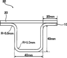
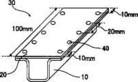
- FIG. 4 is a perspective view showing a state in which a test piece is subjected to orthogonal bending; It is a front view of a test body. It is a perspective view of a test body. FIG. 4 is a perspective view showing a state in which an axial crush test is being performed on a specimen;
- the high-strength steel sheet of the present invention has a steel sheet (base steel sheet), and this steel sheet has a composition and a microstructure described below.
- the high-strength steel sheet of the present invention has a tensile strength of 1180 MPa or more and is excellent in part strength, stretch flange formability, bendability and delayed fracture resistance.
- High strength means that the tensile strength (TS) determined by a tensile test described later is 1180 MPa or more.
- Excellent part strength means that the yield ratio (YR) determined by a tensile test described later is 65% or more.
- Excellent stretch flangeability means that the hole expansion ratio ( ⁇ ) determined by the hole expansion test described later is 30% or more.
- Excellent bendability means that no cracks occur in any of the five test pieces in the bending test described below.
- Excellent delayed fracture resistance means that in the delayed fracture test described later, when TS is 1180 MPa or more and less than 1700 MPa, after 48 hours, when TS is 1700 MPa or more, cracks are confirmed after 24 hours. means not
- the steel sheet (base steel sheet) constituting the high-strength steel sheet of the present invention will be described.
- the steel sheet is, for example, a cold-rolled sheet after undergoing post-heating, which will be described later.
- the plate thickness of the steel plate is not particularly limited, and is usually 0.3 mm or more and 2.8 mm or less.
- composition of the steel sheet (hereinafter also referred to as “chemical composition of the present invention” for convenience) will be described.
- “%” in the component composition of the present invention means “% by mass” unless otherwise specified.
- C (C: 0.090% or more and 0.390% or less) C is one of the important basic components of steel, and particularly in the present invention, it affects the area ratios of martensite and ferrite. If the C content is too low, the area ratio of martensite decreases, making it difficult to achieve a TS of 1180 MPa or more. Therefore, the C content is 0.090% or more, preferably 0.100% or more, and more preferably 0.110% or more. On the other hand, if the C content is too high, the amount of retained austenite increases excessively, and the hardness of martensite generated from the retained austenite during punching greatly increases.
- the C content is 0.390% or less, preferably 0.360% or less, and more preferably 0.350% or less.
- Si 0.01% or more and 2.00% or less
- Si increases the strength of the steel sheet by suppressing the precipitation of cementite in martensite and solid-solution strengthening.
- the Si content is 0.01% or more, preferably 0.20% or more, and more preferably 0.30% or more.
- the Si content is 2.00% or less, preferably 1.50% or less, and more preferably 1.30% or less.
- Mn is one of the important basic components of steel, and particularly in the present invention, it affects the area ratio of martensite. If the Mn content is too low, the martensite area ratio decreases, making it difficult to achieve a TS of 1180 MPa or more. Therefore, the Mn content is 2.00% or more, preferably 2.20% or more, and more preferably 2.50% or more. On the other hand, if the Mn content is too high, the austenite is stabilized, the retained austenite is excessively increased, and the hardness of the martensite generated from the retained austenite at the time of punching greatly increases.
- the Mn content is 4.00% or less, preferably 3.80% or less, and more preferably 3.60% or less.
- the P content is 0.100% or less, preferably 0.070% or less, more preferably 0.050% or less, and even more preferably 0.020% or less.
- the lower limit of the P content is not particularly limited.
- P is a solid-solution strengthening element and increases the strength of the steel sheet. Therefore, the P content is preferably 0.001% or more, more preferably 0.002% or more.
- the S content is 0.0200% or less, preferably 0.0100% or less, more preferably 0.0050% or less, and even more preferably 0.0020% or less.
- the lower limit of the S content is not particularly limited, it is preferably 0.0001% due to production technology restrictions.
- Al (Al: 1.000% or less) Al performs sufficient deoxidation to reduce inclusions in the steel. However, if the Al content is too high, a large amount of ferrite is generated, the hole expansion ratio is lowered, and the stretch flangeability is lowered. Therefore, the Al content is 1.000% or less, preferably 0.500% or less, and more preferably 0.100% or less. On the other hand, in order to stably deoxidize, the Al content is preferably 0.010% or more, more preferably 0.015% or more, and even more preferably 0.020% or more.
- N (N: 0.0100% or less) N exists as a nitride and lowers the ultimate deformability of the steel sheet. As a result, the hole expansion ratio is lowered and the stretch flangeability is lowered. Also, the bendability is reduced. Therefore, the N content is 0.0100% or less, preferably 0.0070% or less, and more preferably 0.0050% or less. Although the lower limit of the N content is not particularly limited, it is preferably 0.0001% due to production technology restrictions.
- O (O: 0.0100% or less) O exists as an oxide and lowers the ultimate deformability of the steel sheet. As a result, the hole expansion ratio is lowered and the stretch flangeability is lowered. Also, the bendability is reduced. Therefore, the O content is 0.0100% or less, preferably 0.0050% or less, more preferably 0.0030% or less, and even more preferably 0.0020% or less. Although the lower limit of the O content is not particularly limited, it is preferably 0.0001% due to production technology restrictions.
- the component composition of the present invention may further contain at least one element selected from the group consisting of the elements described below in mass %.
- Ti, Nb and V each 0.200% or less
- the contents of Ti, Nb and V are each preferably 0.200% or less, more preferably 0.100% or less, and still more preferably 0.080% or less. If the content of each element is within this range, a large amount of coarse precipitates and inclusions are not generated, and the ultimate deformability of the steel sheet is not lowered, so the stretch flangeability (hole expansion ratio) is more excellent. Moreover, bendability is also more excellent.
- the lower limits of the contents of Ti, Nb and V are not particularly limited.
- Ti, Nb and V increase the strength of the steel sheet by forming fine carbides, nitrides or carbonitrides during hot rolling or annealing, which will be described later. Therefore, when Ti, Nb and V are added, the content of Ti, Nb and V is preferably 0.001% or more, and preferably 0.005% or more, from the viewpoint of obtaining the effect of adding these elements. More preferably, 0.010% or more is even more preferable.
- Ta and W each 0.10% or less
- the contents of Ta and W are each preferably 0.10% or less, more preferably 0.08% or less, and still more preferably 0.04% or less. If the content of each element is within this range, a large amount of coarse precipitates and inclusions are not generated, and the ultimate deformability of the steel sheet is not lowered, so the stretch flangeability (hole expansion ratio) is more excellent. Moreover, bendability is also more excellent.
- the lower limits of the Ta and W contents are not particularly limited. However, Ta and W increase the strength of the steel sheet by forming fine carbides, nitrides or carbonitrides during hot rolling or annealing, which will be described later. Therefore, when Ta and W are added, the contents of Ta and W are preferably 0.01% or more, respectively, from the viewpoint of obtaining the effect of adding these elements.
- the B content is preferably 0.0100% or less, more preferably 0.0080% or less, even more preferably 0.0050% or less.
- the lower limit of the B content is not particularly limited. However, B segregates at austenite grain boundaries during annealing, which will be described later, and improves hardenability. Therefore, when B is added, the B content is preferably 0.0003% or more, more preferably 0.0005% or more, and still more preferably 0.0010% or more, from the viewpoint of obtaining the effect of B addition.
- each of Cr, Mo and Ni is preferably 1.00% or less, more preferably 0.90% or less, and still more preferably 0.80% or less. If the content of each element is within this range, coarse precipitates and inclusions do not increase, and the ultimate deformability of the steel sheet does not decrease, resulting in better stretch flangeability (hole expansion ratio). Moreover, bendability is also more excellent.
- the lower limits of the contents of Cr, Mo and Ni are not particularly limited. However, Cr, Mo and Ni improve hardenability.
- the content of Cr, Mo and Ni is preferably 0.01% or more, and preferably 0.02% or more, from the viewpoint of obtaining the effect of adding these elements. More preferably, 0.03% or more is even more preferable.
- the Co content is preferably 0.010% or less, more preferably 0.008% or less, even more preferably 0.006% or less. If the Co content is within this range, coarse precipitates and inclusions do not increase, and the ultimate deformability of the steel sheet does not decrease, so the stretch flange formability (hole expansion ratio) is more excellent. Moreover, bendability is also more excellent.
- the lower limit of Co content is not particularly limited. However, Co improves hardenability. Therefore, when Co is added, the Co content is preferably 0.001% or more, more preferably 0.002% or more, and still more preferably 0.004% or more, from the viewpoint of obtaining the effect of Co addition.
- the Cu content is preferably 1.00% or less, more preferably 0.80% or less, and even more preferably 0.30% or less. If the Cu content is within this range, coarse precipitates and inclusions do not increase and the ultimate deformability of the steel sheet does not decrease, so the stretch flangeability (hole expansion ratio) is more excellent. Moreover, bendability is also more excellent.
- the lower limit of the Cu content is not particularly limited. However, Cu improves hardenability. Therefore, when Cu is added, the Cu content is preferably 0.01% or more, more preferably 0.03% or more, and still more preferably 0.05% or more, from the viewpoint of obtaining the effect of adding Cu.
- the Sn content is preferably 0.200% or less, more preferably 0.100% or less, and even more preferably 0.050% or less. If the Sn content is within this range, cracks do not form inside the steel sheet during casting or hot rolling described later, and the ultimate deformability of the steel sheet does not decrease, so stretch flangeability (hole expansion ratio) is improved. Better. Moreover, bendability is also more excellent.
- the lower limit of the Sn content is not particularly limited. However, Sn improves hardenability. Therefore, when Sn is added, the Sn content is preferably 0.001% or more, more preferably 0.004% or more, and still more preferably 0.008% or more, from the viewpoint of obtaining the effect of Sn addition.
- the Sb content is preferably 0.200% or less, more preferably 0.100% or less, and even more preferably 0.050% or less. If the Sb content is within this range, coarse precipitates and inclusions do not increase, and the ultimate deformability of the steel sheet does not decrease, so the stretch flangeability (hole expansion ratio) is more excellent. Moreover, bendability is also more excellent.
- the lower limit of the Sb content is not particularly limited. However, Sb controls the softening thickness of the surface layer to enable strength adjustment. Therefore, when Sb is added, the Sb content is preferably 0.001% or more, more preferably 0.003% or more, and still more preferably 0.007% or more, from the viewpoint of obtaining the effect of adding Sb.
- the Ca, Mg and REM (rare earth metal) contents are each preferably 0.0100% or less, more preferably 0.0050% or less, and even more preferably 0.0030% or less. If the content of each element is within this range, coarse precipitates and inclusions do not increase, and the ultimate deformability of the steel sheet does not decrease, resulting in better stretch flangeability (hole expansion ratio). Moreover, bendability is also more excellent.
- the lower limits of the Ca, Mg and REM contents are not particularly limited. However, Ca, Mg and REM spheroidize the shape of nitrides and sulfides and improve the ultimate deformability of the steel sheet.
- the contents of Ca, Mg, and REM are each preferably 0.0002% or more, and 0.0005% or more, from the viewpoint of obtaining the effect of adding these elements. More preferably, 0.0010% or more is even more preferable.
- Zr and Te each 0.100% or less
- the contents of Zr and Te are each preferably 0.100% or less, more preferably 0.080% or less, and still more preferably 0.050% or less. If the content of each element is within this range, coarse precipitates and inclusions do not increase, and the ultimate deformability of the steel sheet does not decrease, resulting in better stretch flangeability (hole expansion ratio). Moreover, bendability is also more excellent.
- the lower limits of the contents of Zr and Te are not particularly limited. However, Zr and Te spheroidize the shape of nitrides and sulfides and improve the ultimate deformability of the steel sheet. Therefore, when Zr and Te are added, the contents of Zr and Te are preferably 0.001% or more, more preferably 0.003% or more, respectively, from the viewpoint of obtaining the effect of adding these elements. More preferably 0.007% or more.
- the Hf content is preferably 0.10% or less, more preferably 0.08% or less, and even more preferably 0.05% or less. If the Hf content is within this range, coarse precipitates and inclusions do not increase, and the ultimate deformability of the steel sheet does not decrease, so the stretch flangeability (hole expansion ratio) is more excellent. Moreover, bendability is also more excellent.
- the lower limit of Hf content is not particularly limited. However, Hf spheroidizes the shape of nitrides and sulfides and improves the ultimate deformability of the steel sheet. Therefore, when Hf is added, the Hf content is preferably 0.01% or more, more preferably 0.02% or more, from the viewpoint of obtaining the effect of adding Hf.
- the Bi content is preferably 0.200% or less, more preferably 0.100% or less, and even more preferably 0.030% or less. If the Bi content is within this range, coarse precipitates and inclusions do not increase, and the ultimate deformability of the steel sheet does not decrease, so the stretch flangeability (hole expansion ratio) is more excellent. Moreover, bendability is also more excellent.
- the lower limit of the Bi content is not particularly limited. However, Bi is an element that reduces segregation. Therefore, when Bi is added, the Bi content is preferably 0.001% or more, more preferably 0.002% or more, and still more preferably 0.004% or more, from the viewpoint of obtaining the effect of Bi addition.
- the balance in the component composition of the present invention consists of Fe and unavoidable impurities.
- Fe for Ti, Nb, V, Ta, W, B, Cr, Mo, Ni, Co, Cu, Sn, Sb, Ca, Mg, REM, Zr, Te, Hf and Bi, the content of each element is If the content is less than the lower limit of the preferred range, the element is treated as an unavoidable impurity because it does not impair the effects of the present invention.
- microstructure of the steel sheet (hereinafter also referred to as "the microstructure of the present invention” for convenience) will be described.
- the area ratio of martensite is 70% or more, preferably 75% or more, more preferably 80% or more, and even more preferably 85% or more.
- the upper limit is not particularly limited, and this effect can be obtained even if the area ratio of martensite is 100%.
- Martensite includes lower bainite, martensite self-tempered during cooling performed in annealing described later, martensite tempered by post-heating described later, and the like. The observation position of martensite is the 1/4 position of the plate thickness of the steel plate, as will be described later.
- the area ratio of ferrite is 10% or less, preferably 8% or less, more preferably 5% or less, and even more preferably 3% or less.
- the lower limit is not particularly limited, and this effect can be obtained even if the area ratio of ferrite is 0%.
- Ferrites include allotriomorph ferrite, idiomorph ferrite, Widmanstetten ferrite, upper bainite, and the like. The observation position of the ferrite is the 1/4 position of the plate thickness of the steel plate, as will be described later.
- the method for measuring the area ratios of martensite and ferrite is as follows. First, a sample is cut out from a steel plate so that the plate thickness cross section (L cross section at the position of 1/4 of the plate thickness) parallel to the rolling direction is the observation surface. The observation surface of the sample is mirror-polished with diamond paste, then finished with colloidal silica, and etched with 1% by volume of nital to expose the structure. Next, the observation surface of the sample is observed at a magnification of 3000 times using a scanning electron microscope (SEM) under the condition of an acceleration voltage of 10 kV to obtain SEM images for 3 fields of view. The area ratio of each tissue is calculated from the obtained SEM image using Adobe Photoshop (manufactured by Adobe Systems).
- Adobe Photoshop manufactured by Adobe Systems
- the area ratio of each tissue is obtained by dividing the area of each tissue by the measured area.
- the area ratio of each tissue is calculated for three fields of view, and the average value thereof is taken as the area ratio of each tissue.
- ferrite has a gray flat structure
- martensite has a hierarchical structure with fine irregularities inside, and both can be distinguished from each other.
- the area ratio of retained austenite is 10% or less, preferably 8% or less, more preferably 5% or less, and even more preferably 4% or less.
- the lower limit is not particularly limited, and this effect can be obtained even if the area ratio of retained austenite is 0%.
- the method for measuring the area ratio of retained austenite is as follows. First, the steel plate is ground so that the 1/4 position of the plate thickness (the position corresponding to 1/4 of the plate thickness in the depth direction from the steel plate surface) is the measurement surface, and then chemical polishing is performed to further 0.1 mm. Grind and get a sample. The (200) plane, (220) plane and (311) plane of fcc iron (austenite) and the (200) plane of bcc iron were measured using an X-ray diffractometer using a Co K ⁇ ray source. The integrated reflection intensities of the (211) and (220) planes are measured.
- the intensity ratio of the integrated reflection intensity of each surface of fcc iron to the integrated reflection intensity of each surface of bcc iron is obtained. Let the average value of nine intensity ratios be the volume fraction of retained austenite. The volume fraction of retained austenite is regarded as the area fraction of retained austenite.
- the ratio of the number of martensite blocks in which metastable carbides are present to the number of martensite blocks is 2% or more, preferably 5% or more, and 10%. 20% or more is more preferable, and 30% or more is particularly preferable.
- the upper limit of the ratio p is not particularly limited, and may be 100%.
- Metastable carbides are metastable carbides that precipitate during the tempering process of martensite.
- Metastable carbides are, for example, Fe carbides (iron-based carbides) other than cementite, and include at least one carbide selected from the group consisting of epsilon ( ⁇ ) carbides, eta ( ⁇ ) carbides and chi ( ⁇ ) carbides. be done.
- the method for measuring the ratio of the number of martensite blocks in which metastable carbides are present (ratio p) to the number of martensite blocks is as follows. First, the steel plate is ground so that the 1/4 position of the plate thickness (the position corresponding to 1/4 of the plate thickness in the depth direction from the steel plate surface) is the observation surface, and then electrolytically polished to obtain a sample. make. Observation surfaces of the prepared samples are observed using a transmission electron microscope (TEM) under the condition of an acceleration voltage of 200 kV. Since the dislocation density of martensite is significantly higher than that of ferrite and retained austenite, martensite can be distinguished from each other and identified within the observation field by observing the strain contrast in the TEM bright-field image.
- TEM transmission electron microscope
- a martensite block is one of the structural units of martensite having a hierarchical structure, and is a group of laths having the same habit plane and the same crystal orientation.
- the diffraction contrast differs for each block in martensite, it can be distinguished from other structural units such as packets and laths, and martensite blocks can be identified.
- an electron beam is incident from the [100] orientation of the martensite block, an electron diffraction pattern of the matrix martensite is obtained.
- Adjacent martensitic blocks have different crystal orientations across the block boundaries, and thus have different contrasts in bright-field images, so that they can be distinguished from each other.
- FIG. 1 is an example of an electron diffraction pattern of martensite in which carbides are present. If carbides are present in the single observed martensite block, the electron diffraction pattern of the carbides is obtained in addition to the electron diffraction pattern of the matrix martensite ( ⁇ ), as shown in FIG.
- the martensite block is: Defined as martensitic blocks in which metastable carbides are present.
- the ratio of the number of martensite blocks in which metastable carbides are present to the number of martensite blocks is "the number of martensite blocks whose ratio d c / dm to the number of martensite blocks is 1.020 or more and 1.150 or less.
- Metastable carbides may exist inside martensite blocks or at boundaries such as block boundaries, but preferably inside martensite blocks.
- the obtained value is defined as the ratio (ratio p) [%] of the number of martensite blocks in which the metastable carbide exists to the number of martensite blocks.
- the number density of metastable carbides in a martensite block in which metastable carbides are present is preferably 1 ⁇ 10 6 /mm 2 or more, and 10 ⁇ 10 6 /mm 2 or more is more preferable, and 100 ⁇ 10 6 /mm 2 or more is even more preferable.
- the upper limit of the number density n is not particularly limited . /mm 2 is more preferred, and 10,000 ⁇ 10 6 /mm 2 is even more preferred.
- the number density of metastable carbides (number density n) in a martensite block in which metastable carbides are present is obtained as follows. In measuring the fraction p using TEM as described above, a selected area electron diffraction pattern was obtained in a single martensite block in which metastable carbides were present, and the electron diffraction spots obtained from the metastable carbides were used to obtain a dark field get the image. In dark field images, metastable carbides exhibit a white contrast. A 300 nm ⁇ 300 nm area is imaged inside a single martensite block and the number of metastable carbides is counted. It should be noted that adjacent martensite blocks may exist in a region of 300 nm ⁇ 300 nm across a block boundary.
- the area of a martensite block in which metastable carbides are present is defined as the area of a single martensite block for which a selected area electron diffraction pattern was obtained. Adjacent martensitic blocks have different crystal orientations across the block boundaries, and thus have different contrasts in bright-field images, so that they can be distinguished from each other.
- the average equivalent circle diameter of the metastable carbides in the martensite block is preferably 20 nm or less, more preferably 5 nm or less.
- the average equivalent circle diameter of the metastable carbides in the martensite block is determined as follows. In measuring the fraction p using TEM as described above, a selected area electron diffraction pattern was obtained in a single martensite block in which metastable carbides were present, and the electron diffraction spots obtained from the metastable carbides were used to obtain a dark field get the image. In dark field images, metastable carbides exhibit a white contrast. A dark-field image of a 300 nm ⁇ 300 nm area is taken inside a single martensite block and image processing is performed to obtain a binarized image so that the metastable carbides can be distinguished. By particle analysis of the binarized image, the equivalent circle diameter is obtained for each metastable carbide particle.
- the binarized image is divided using the Watershed method. Equivalent circle diameters are determined for each of all the metastable carbides present in the area of 300 nm ⁇ 300 nm (for 3 fields of view). The average value of the equivalent circle diameters for the three fields of view is obtained, and this is taken as the average value of the equivalent circle diameters of the metastable carbides in the martensite block.
- the microstructure of the present invention may have a structure (residual structure) other than the martensite, ferrite and retained austenite described above.
- the area ratio of the remaining structure is preferably 3% or less because the effect of the present invention is not impaired.
- residual structures include pearlite; carbides such as cementite precipitated in ferrite; alloy carbonitrides precipitated in ferrite; other structures known as steel plate structures; Metastable carbides precipitated in martensite and iron-based carbides such as cementite precipitated in martensite are not included in the residual structure.
- the steel sheet (base steel sheet) constituting the high-strength steel sheet of the present invention preferably has a soft layer on its surface layer. Since the soft layer contributes to suppressing the progress of bending cracks during press forming and collision, the bendability is more excellent, and the fracture resistance at the time of collision is also excellent.
- the surface layer is a portion extending from the surface of the steel sheet (cold-rolled sheet) to 200 ⁇ m in the sheet thickness direction.
- the soft layer is a decarburized layer, more specifically, a portion having a Vickers hardness of 85% or less with respect to the Vickers hardness at the position of 1/4 thickness of the steel sheet (cold-rolled sheet).
- the Vickers hardness at the 1/4 position of the steel plate thickness is the cross section (parallel to the surface of the steel plate) surface) Vickers hardness.
- the Vickers hardness is measured according to JIS Z 2244-1:2020 with a load of 10 gf.
- the thickness of the soft layer is preferably 3 ⁇ m or more, more preferably 7 ⁇ m or more, and even more preferably 11 ⁇ m or more.
- the thickness of the soft layer is preferably 150 ⁇ m or less, more preferably 100 ⁇ m or less, and even more preferably 80 ⁇ m or less.
- the thickness of the soft layer is obtained as follows. First, using a Vickers hardness tester, the Vickers hardness is measured at intervals of 1 ⁇ m from a position 1 ⁇ m in the plate thickness direction from the surface of the steel sheet to a position 100 ⁇ m in the plate thickness direction with a load of 10 gf. Next, the Vickers hardness is measured at intervals of 20 ⁇ m to the center of the plate thickness. Note that the Vickers hardness is measured after smoothing a cross section (L cross section) of the steel sheet parallel to the rolling direction by wet polishing.
- a portion (region) where the Vickers hardness measured in this way is 85% or less with respect to the Vickers hardness at the 1/4 position of the plate thickness of the steel plate is defined as the soft layer, and the plate thickness of this portion (region) The thickness in the direction is determined as the thickness of the soft layer (unit: ⁇ m).
- ratio r The nano-hardness is measured at 300 points or more (for example, 512 points) within a range of 50 ⁇ m ⁇ 50 ⁇ m at 1/4 position in the plate thickness direction of the soft layer. At this time, the ratio of measurement points with a nano-hardness of 7.0 GPa or more to the total number of measurement points is called "ratio r".
- the ratio r is, for example, 0.20 or less, preferably 0.15 or less, and more preferably 0.10 or less.
- a smaller ratio r means less hard structures (such as martensite) and inclusions in the microstructure. When the microstructure has few hard structures and inclusions, void formation, void connection, and crack propagation can be suppressed more effectively during press forming and collision. That is, the bendability is further excellent, and the breakage resistance at the time of collision is further excellent (the value of SF max , which will be described later, is favorable).
- standard deviation ⁇ A and standard deviation ⁇ B The standard deviation of the nano-hardness at the 1 ⁇ 4 position in the plate thickness direction of the soft layer is called “standard deviation ⁇ A ”.
- standard deviation ⁇ B The standard deviation of the nano-hardness at the half depth position in the thickness direction of the soft layer is called “standard deviation ⁇ B ".
- the standard deviation ⁇ A is, for example, 2.0 GPa or less, preferably 1.8 GPa or less, and more preferably 1.7 GPa or less.
- the standard deviation ⁇ B is, for example, 2.5 GPa or less, preferably 2.2 GPa or less, and more preferably 2.1 GPa or less.
- a small standard deviation ⁇ A and a small standard deviation ⁇ B means that the hardness difference of each structure in the microstructure is small. In this case, formation of voids, connection of voids, and propagation of cracks can be further suppressed during press forming and collision. That is, the bendability is further improved, and the breakage resistance at the
- Nanohardness is hardness measured using the nanoindentation method. More specifically, the nano-hardness at the 1/4 position and 1/2 position in the plate thickness direction depth of the soft layer is obtained as follows. First, when a plated layer and/or a metal plated layer (both of which will be described later) are formed on the surface of the steel sheet, the plated layer and/or the metal plated layer are peeled off. After that, mechanical polishing is performed from the surface of the steel plate to the thickness direction depth 1/4 position (or 1/2 position) of the soft layer, then buffing is performed using diamond and alumina, and colloidal polishing is performed. Polishing with silica is performed.
- an L cross-section at the 1/4 position (or 1/2 position) of the depth in the plate thickness direction of the soft layer is obtained.
- the nano-hardness of the L-section of the soft layer is measured under the conditions of a load of 500 ⁇ N, a measurement area of 50 ⁇ m ⁇ 50 ⁇ m, and a dot interval of 2 ⁇ m.
- the high-strength steel sheet of the present invention may have a metal plating layer (also referred to as "pre-annealing plating layer") on the surface of the steel sheet.
- the metal plating layer is a layer different from the plating layer described later.
- a metal electroplating layer is preferable as the metal plating layer. Since the metal plating layer contributes to suppressing the occurrence of bending cracks during press forming and collision, the bendability is more excellent, and the fracture resistance at the time of collision is also excellent.
- the metal plating layer is preferably a metal plating layer having a component composition composed of Fe and unavoidable impurities (hereinafter also referred to as "Fe-based metal plating layer”).
- the metal plating layer is preferably a metal plating layer having a composition composed of Ni and unavoidable impurities (hereinafter also referred to as "Ni-based metal plating layer").
- the component composition of the Fe-based metal plating layer is at least one selected from the group consisting of B, C, P, N, O, Ni, Mn, Mo, Zn, W, Pb, Sn, Cr, V and Co. elements in a total amount of 10% by mass or less.
- the C content is preferably 0.08% by mass or less.
- the adhesion amount (per side) of the metal plating layer is more than 0 g/m 2 , preferably 2.0 g/m 2 or more, more preferably 5.0 g/m 2 or more, and further preferably 8.0 g/m 2 or more. preferable.
- the upper limit of the adhesion amount (per side) of the metal plating layer is not particularly limited, but from the viewpoint of cost, it is preferably 60.0 g/m 2 or less, more preferably 50.0 g/m 2 or less. /m 2 or less is more preferable, 30.0 g/m 2 or less is particularly preferable, and 20.0 g/m 2 or less is most preferable.
- the adhesion amount of the metal plating layer is obtained as follows. First, a steel plate on which a metal plating layer is formed is cut into a size of 10 mm ⁇ 15 mm and embedded in resin to obtain an embedded sample. Any three points in the cross section of the embedded sample are observed using a scanning electron microscope (SEM) at an acceleration voltage of 15 kV at a magnification of 2000 to 10000 times depending on the thickness of the metal plating layer, and metal plating Measure the layer thickness. By multiplying the average value of the thicknesses at the three locations by the specific gravity of the metal element (for example, Fe) of the metal plating layer, it is converted into the adhesion amount per one side of the metal plating layer.
- SEM scanning electron microscope
- the high-strength steel sheet of the present invention may have a plating layer on the surface of the steel sheet or metal plating layer.
- the plated layer is a layer different from the metal plated layer described above, and is formed by a plating process to be described later.
- the plated layer is not particularly limited, and examples thereof include a hot-dip plated layer and an electroplated layer.
- the plated layer may be an alloyed plated layer (alloyed plated layer).
- the plating layer includes a zinc plating layer (Zn plating layer), an Al plating layer, etc. Among them, a zinc plating layer is preferable.
- the galvanized layer may contain elements such as Al and Mg.
- the composition of the plated layer is not particularly limited, and may be a general composition.
- the plating layer when it is a hot-dip galvanized layer or an alloyed hot-dip galvanized layer, it generally contains Fe: 20% by mass or less, Al: 0.001 to 1.0% by mass, and Pb , Sb, Si, Sn, Mg, Mn, Ni, Cr, Co, Ca, Cu, Li, Ti, Be, Bi and at least one selected from the group consisting of REM in total 0 to 3.5% by mass and the balance being Zn and unavoidable impurities.
- the coating weight per side of the plated layer is preferably 20 to 80 g/m 2 .
- An alloyed hot-dip galvanized layer obtained by alloying a hot-dip galvanized layer with such an adhesion amount is also preferable.
- the Fe content in the plated layer is preferably less than 7% by mass.
- the Fe content in the plated layer is preferably 7 to 20% by mass, more preferably 7 to 15% by mass.
- the adhesion amount of the coating layer is determined as follows. First, 0.6 g of a corrosion inhibitor (IBIT 700BK (registered trademark), manufactured by Asahi Kagaku Kogyo Co., Ltd.) that suppresses the corrosion of Fe is added to 1 L of a 10% by mass hydrochloric acid aqueous solution to obtain a treatment liquid. A steel sheet having a plating layer formed thereon is immersed as a test material in the obtained treatment liquid to dissolve the plating layer. By measuring the mass of the test material before and after dissolving the plating layer, the mass decrease of the test material is obtained. The coating amount (g/m 2 ) of the coating layer is obtained by dividing the obtained mass reduction amount by the surface area of the steel sheet (the area of the portion covered with the coating layer).
- a corrosion inhibitor IBIT 700BK (registered trademark) that suppresses the corrosion of Fe is added to 1 L of a 10% by mass hydrochloric acid aqueous solution to obtain a treatment liquid.
- the manufacturing method of the present invention is also a method of manufacturing the above-described high-strength steel sheet of the present invention.
- ⁇ Hot rolling, pickling and cold rolling> In the manufacturing method of the present invention, first, a steel slab having the chemical composition of the present invention is subjected to hot rolling, pickling, and cold rolling to obtain a cold-rolled sheet.
- a method for melting molten steel to be a steel slab (steel material) is not particularly limited, and a known melting method using a converter, an electric furnace, or the like can be employed.
- Steel slabs are preferably produced by continuous casting to prevent macro segregation, but they can also be produced by other methods such as ingot casting and thin slab casting.
- the manufactured steel slab is once cooled to room temperature, then heated again, subjected to hot rolling (rough rolling and finish rolling), and then coiled.
- hot rolling rough rolling and finish rolling
- a hot-rolled sheet is obtained.
- the produced steel slab may be charged into the heating furnace as a warm piece without being cooled to room temperature, or may be rolled (roughly rolled) immediately after being slightly heated.
- a rough rolled plate is obtained by rough rolling a steel slab.
- the temperature at which the steel slab is roughly rolled (slab heating temperature) is preferably 1100° C. or higher from the viewpoint of dissolving carbides and reducing the rolling load.
- the slab heating temperature is preferably 1300° C. or lower in order to prevent an increase in scale loss.
- the slab heating temperature is the surface temperature of the steel slab. When the slab heating temperature is lowered, it is preferable to heat the rough rolled sheet using a bar heater or the like before finish rolling from the viewpoint of preventing troubles in hot rolling.
- the temperature (finish rolling temperature) at which finish rolling is performed is preferably the Ar3 transformation point or higher. This reduces the rolling load. Furthermore, the rolling reduction in the non-recrystallized state of austenite is reduced, the development of an abnormal structure elongated in the rolling direction is suppressed, and the workability is excellent. Finish rolling may be carried out continuously by joining rough rolled plates. The rough rolled sheet may be wound once before the finish rolling is performed. In order to reduce the rolling load, part or all of the finish rolling may be lubricated rolling. Lubricating rolling is also preferable from the viewpoint of homogenizing the shape and quality of the steel sheet. The coefficient of friction during lubricating rolling is preferably in the range of 0.10 to 0.25.
- the coiling temperature after hot rolling is preferably 300 to 700°C from the viewpoint of improving the threadability during cold rolling and annealing, which will be described later.
- the hot-rolled sheet obtained by hot rolling is pickled.
- oxides on the surface of the hot-rolled sheet are removed, and the high-strength steel sheet, which is the final product, is excellent in chemical conversion treatability and quality of the coating layer.
- the pickling may be performed once, or may be carried out in a plurality of times.
- the hot-rolled sheet after pickling is optionally subjected to softening heat treatment and then cold-rolled.
- a cold-rolled sheet is thus obtained.
- the conditions for cold rolling are not particularly limited, but the cumulative reduction in cold rolling is preferably 20 to 75%.
- the number of rolling passes and the rolling reduction of each pass are not particularly limited.
- the cold-rolled sheet thus obtained is optionally subjected to a metal plating treatment (pre-annealing plating treatment) described below, and then subjected to annealing and post-heating described below.
- a metal plating treatment pre-annealing plating treatment
- the hot-rolled sheet (including the hot-rolled sheet after pickling) and the cold-rolled sheet described above may be subjected to some kind of annealing before the metal plating treatment (pre-annealing plating treatment) is performed.
- the metal plating treatment is a treatment for forming the above-described metal plating layer (pre-annealing plating layer) on the surface (at least one side) of the cold-rolled sheet before annealing, which will be described later.
- metal electroplating treatment metal electroplating treatment is preferable.
- a metal electroplating layer can be formed as a metal plating layer.
- an electroplating bath used for metal electroplating a sulfuric acid bath, a hydrochloric acid bath, a mixed bath of both, or the like can be used.
- the adhesion amount of the formed metal electroplating layer can be adjusted by the energization time of the metal electroplating process.
- Metal elements contained in the electroplating bath include, for example, Cr, Mn, Fe, Co, Ni, Cu, Ga, Ge, As, Ru, Rh, Pd, Ag, Cd, In, Sn, Sb, Os, Ir , Rt, Au, Hg, Ti, Pb and Bi. Of these, Fe or Ni is preferred.
- the electroplating bath can further contain at least one element selected from the group consisting of B, C, P, N, O, Ni, Mn, Mo, Zn, W, Pb, Sn, Cr, V and Co. .
- the total content of these elements in the electroplating bath is preferably such that the total content of these elements in the formed metal plating layer is 10% by mass or less.
- the content of Fe ions (Fe 2+ ) or Ni ions (Ni 2+ ) in the electroplating bath before starting energization is preferably 0.5 to 2.0 mol/L.
- the electroplating bath can contain metallic elements as metal ions and non-metallic elements as part of boric acid, phosphoric acid, nitric acid, organic acids, and the like.
- the electroplating bath may further contain a conductivity aid such as sodium sulfate or potassium sulfate; a chelating agent; a pH buffer;
- the temperature of the electroplating bath is preferably 30 to 85° C. from the viewpoint of constant temperature maintenance.
- the pH of the electroplating bath is preferably 1.0 or more from the viewpoint of preventing a decrease in current efficiency due to hydrogen generation, and is preferably 3.0 or less in consideration of electrical conductivity.
- the current density is preferably 10 A/dm 2 or more from the viewpoint of productivity, and preferably 150 A/dm 2 or less from the viewpoint of facilitating control of the amount of the metal electroplating layer to be formed.
- the speed at which the cold-rolled sheet is passed through the electroplating bath (sheet threading speed) is preferably 5 mpm or more from the viewpoint of productivity, and 150 mpm from the viewpoint of stably controlling the adhesion amount of the metal electroplating layer to be formed. The following are preferred.
- degreasing and water washing for cleaning the surface of the cold-rolled sheet, and pickling and water washing for activating the surface of the cold-rolled sheet may be performed.
- the method of degreasing and washing with water is not particularly limited, and conventional methods can be used.
- Various acid solutions such as sulfuric acid, hydrochloric acid, nitric acid, and mixtures thereof can be used for pickling. Among them, sulfuric acid, hydrochloric acid, or mixtures thereof are preferred.
- the concentration of the acid solution is preferably 1 to 20% by mass in consideration of the ability to remove the oxide film and the prevention of surface defects due to over-acid pickling. Antifoaming agents, pickling accelerators, pickling inhibitors, and the like may be added to the acid solution.
- the obtained cold-rolled sheet is annealed.
- the cold-rolled sheet is heated at a heating temperature described later, and then cooled to a cooling stop temperature described later.
- the heating temperature is 800° C. or higher, preferably 820° C. or higher.
- the upper limit of the heating temperature is not particularly limited, 950° C. is preferable from the viewpoint of workability and the like.
- the time (heating time) for heating the cold-rolled sheet at the heating temperature is not particularly limited, but if it is too short, the reverse transformation to austenite may not proceed sufficiently, so it is preferably 30 seconds or longer, more preferably 60 seconds or longer.
- the upper limit of the heating time is not particularly limited, and is, for example, 6000 s, preferably 3000 s. In addition, "s" means a second.
- the dew point of the atmosphere when the cold-rolled sheet is heated at the above-described heating temperature is preferably ⁇ 30° C. or higher, more preferably ⁇ 20° C. or higher, still more preferably ⁇ 15° C. or higher, and particularly preferably ⁇ 5° C. or higher.
- the dew point is preferably 30° C. or less from the viewpoint of suitably preventing the surface oxidation of the metal plating layer (plating layer before annealing) and improving the adhesion of the plating layer formed by the plating treatment described later. .
- ⁇ Retention time t1 in temperature range T1 above Ms ° C. and 700 °C or less 1000 s or less>>
- the cold-rolled sheet that is cooled to the cooling stop temperature after heating passes through a temperature range T1 of Ms°C or higher and 700°C or lower. If the cold-rolled sheet stays in the temperature region T1 for too long (residence time t1), excessive ferrite transformation occurs and the area ratio of ferrite increases, failing to obtain good stretch flangeability and bendability. Therefore, the residence time t1 is 1000 s or less, preferably 500 s or less, and more preferably 300 s or less.
- the lower limit of the residence time t1 is not particularly limited, it is preferably 1 s, more preferably 5 s, and still more preferably 10 s from the viewpoint of reducing the burden of capital investment.
- Cooling in the temperature range T1 may be either continuous cooling or intermittent cooling.
- intermittent cooling is preferable from the viewpoint of alleviating the stress generated due to structural changes during cooling, achieving a good steel sheet shape, and obtaining better stretch flangeability and bendability.
- the first average cooling rate v1 is 1.0° C./s or higher, preferably 2.0° C./s or higher, and more preferably 3.0° C./s or higher.
- the first average cooling rate v1 is 40.0° C./s or less, preferably 25.0° C./s or less, and more preferably 20.0° C./s or less.
- Continuous cooling is preferable for cooling in the temperature range T2.
- the second average cooling rate v2 is 0.3° C./s or higher, preferably 0.5° C./s or higher, and more preferably 1.0° C./s or higher.
- the second average cooling rate v2 is less than the first average cooling rate v1. If the second average cooling rate v2 is equal to or higher than the first average cooling rate v1, the diffusion of C in martensite will be insufficient, and the precursor stage of metastable carbide will not occur sufficiently. As a result, in the subsequent post-heating, the precipitation of metastable carbides is suppressed, the ratio p becomes low, and the delayed fracture resistance becomes insufficient.
- Continuous cooling is preferable for cooling in the temperature range T3.
- Ms is the temperature (Ms point) at which martensite transformation begins to occur, and the value measured by the Formaster test is used.
- the cold-rolled sheet may be subjected to bending and unbending one or more times. Bending and unbending is preferably performed in a temperature range of 150°C or higher and Ms°C or lower. Bending and unbending are bending performed in a direction perpendicular to the rolling direction and subsequent unbending. Bending and unbending promotes martensite transformation. As a result, metastable carbides are efficiently precipitated in post-heating, which will be described later, and the ratio (ratio p) of the number of martensite blocks in which metastable carbides are present to the number of martensite blocks is increased.
- the number of times of bending and unbending is preferably 1 or more, more preferably 2 or more, and even more preferably 3 or more.
- the number of bending and unbending processes is preferably 10 times or less, more preferably 8 times or less, and even more preferably 5 times or less.
- the method of bending and unbending is not particularly limited, but generally includes a method using rolls.
- the diameter of the roll used for bending and unbending is not particularly limited, but is preferably 300 to 2000 mm.
- ⁇ Cooling stop temperature 150°C or less>>
- the cooling stop temperature is 150° C. or lower. This fully completes the martensite transformation. If the cooling stop temperature is higher than 150°C, the untransformed austenite does not transform into martensite, the amount of retained austenite becomes excessive, and good part strength and stretch flangeability cannot be obtained.
- the cold-rolled sheet cooled to the cooling stop temperature may be further cooled to room temperature.
- the cooling rate from the cooling stop temperature to room temperature is not particularly limited.
- the cooling method is also not particularly limited, and any method can be adopted, such as gas jet cooling, mist cooling, water cooling, air cooling, and the like.
- ⁇ Post-heating> The annealed (heated and cooled) cold-rolled sheet is then post-heated.
- metastable carbides that improve the delayed fracture resistance are precipitated in the martensite blocks generated during the cooling in the annealing described above.
- a high-strength steel sheet having a TS of 1180 MPa or more which is excellent in delayed fracture resistance while having good part strength, stretch-flangeability and bendability, can be obtained.
- the annealed cold-rolled sheet is subjected to post-heating at a temperature X (unit: ° C.), which is the highest temperature reached, and a holding time Y (unit: s) at temperature X-10 ° C. or higher. It is carried out under the conditions satisfying the following formula 1.
- a temperature X unit: ° C.
- Y unit: s
- ratio p the ratio of the number of martensite blocks in which metastable carbides are present
- Formula 1 8000 ⁇ (273+X) ⁇ (20+Log(Y/3600)) ⁇ 12000
- variable part Z (273+X) ⁇ (20+Log(Y/3600))" in Equation 1 above is hereinafter referred to as "variable part Z" for convenience.
- the value of the variable part Z is 8000 or more, preferably 8500 or more, and more preferably 9000 or more, because the ratio p is high.
- the value of the variable part Z is 12,000 or less, preferably 11,500 or less, and more preferably 11,000 or less, because the ratio p is high.
- the temperature X (unit: °C) preferably satisfies Formula 2 below. This increases the metastable carbide number density (number density n) in the martensite block where metastable carbides are present.
- Formula 2 100 ⁇ X ⁇ 400
- the temperature X is preferably 100° C. or higher, more preferably 120° C. or higher, and even more preferably 150° C. or higher, because the number density n increases.
- the temperature X is preferably 400° C. or lower, more preferably 380° C. or lower, and even more preferably 350° C. or lower.
- the high-strength steel sheet of the present invention is obtained by the production method of the present invention.
- the obtained high-strength steel sheet of the present invention is a plated steel sheet having a plated layer.
- the cold-rolled sheet may be plated.
- the plating treatment for example, hot dip galvanizing treatment (treatment for forming a hot dip galvanized layer), alloying hot dip galvanizing treatment (alloying hot dip galvanizing by performing alloying treatment after hot dip galvanizing treatment processing to form a layer) and the like.
- An electroplating layer may be formed by an electroplating process. The plating treatment is performed, for example, on the cold-rolled sheet staying in the temperature range T1 (Ms° C. or higher and 700° C. or lower).
- the hot-dip galvanizing treatment When the hot-dip galvanizing treatment is performed, it is preferable to immerse the cold-rolled sheet in a galvanizing bath at 440 to 500° C., and then adjust the coating amount of the coating layer by gas wiping or the like.
- the amount of Al in the zinc plating bath is preferably 0.10-0.23% by mass.
- the hot-dip galvanizing treatment is preferably carried out during residence in the above-described temperature range T1 (Ms° C. or higher and 700° C. or lower) during annealing.
- the temperature of the alloying treatment is too low, the Zn—Fe alloying rate becomes excessively slow, which may impair the productivity.
- the temperature of the alloying treatment is too high, untransformed austenite may transform into pearlite and the TS may decrease.
- Skin pass rolling may be performed after the plating treatment.
- the rolling reduction in skin pass rolling is preferably 0.05% or more from the viewpoint of increasing the yield strength.
- the upper limit of the rolling reduction is not particularly limited, it is preferably 1.50% from the viewpoint of productivity.
- Skin-pass rolling may be performed online or offline.
- the skin pass with the target rolling reduction may be performed at once, or may be performed in several steps.
- the obtained cold-rolled sheets were subjected to annealing and post-heating under the conditions shown in Table 3 below to obtain steel sheets.
- the heating time at the heating temperature was 200 seconds.
- the bending and unbending processing was performed in the temperature range T2 and the temperature range T3.
- ⁇ Plating treatment Some of the cold-rolled sheets were subjected to hot-dip galvanizing treatment during retention in the temperature range T1 (Ms°C or higher and 700°C or lower) to form a coating layer (hot-dip galvanizing layer) on both sides. . That is, a hot-dip galvanized steel sheet (GI) was obtained. A hot-dip galvanizing bath (bath temperature: 470° C.) containing 0.20% by mass of Al and the balance being Zn and unavoidable impurities was used for the hot-dip galvanizing treatment. The adhesion amount per side of the hot-dip galvanized layer was about 45 g/m 2 . The composition of the formed hot-dip galvanized layer contained 0.1 to 1.0% by mass of Fe and 0.2 to 1.0% by mass of Al, with the balance being Fe and unavoidable impurities. .
- Another part of the cold-rolled sheet is subjected to alloying hot-dip galvanizing treatment while staying in the temperature range T1 (Ms ° C. or higher and 700 ° C. or lower) to obtain a coating layer (alloyed hot-dip zinc plating layer) was formed. That is, an alloyed hot-dip galvanized steel sheet (GA) was obtained.
- a hot dip galvanizing bath bath temperature: 470° C.
- the alloying treatment was performed at 550°C.
- the amount of the alloyed hot-dip galvanized layer deposited on one side was about 45 g/m 2 .
- the composition of the galvannealed layer thus formed contained 7 to 15% by mass of Fe and 0.1 to 1.0% by mass of Al, with the balance being Fe and unavoidable impurities.
- GI when a hot-dip galvanized layer is formed
- GA when an alloyed hot-dip galvanized layer is formed
- CR when a galvannealed layer is not formed
- Type in Table 3 below. described in the column.
- hot-dip galvanized steel sheets (GI) and alloyed hot-dip galvanized steel sheets (GA) are also simply referred to as “steel sheets”.
- a bending test was performed in accordance with JIS Z 2248. Specifically, a strip-shaped test piece having a width of 30 mm and a length of 100 mm was taken from the obtained steel sheet so that the direction parallel to the rolling direction of the steel sheet was the axial direction of the bending test. A 90° V bending test was performed using the sampled test piece under the conditions of an indentation load of 100 kN and a pressing holding time of 5 seconds. The maximum bending radius R at which the value (R/t) obtained by dividing the bending radius R by the plate thickness t is 5 or less (for example, when the plate thickness t is 1.4 mm, the bending radius R is 7.0 mm). A bending test was performed on two specimens.
- ⁇ Delayed fracture test A strip-shaped test piece having a width of 70 mm and a length of 16 mm was taken from the obtained steel sheet so that the direction perpendicular to the rolling direction of the steel sheet was the mechanically ground end face. Bending deformation was applied to the sampled test piece so that a stress equivalent to 800 MPa was applied to the central portion by four-point bending. Next, the bending-deformed test piece was immersed in a 0.1% by mass ammonium thiocyanate solution at 25° C. whose pH was adjusted to 5.0 using a McIlvain buffer. After that, the test piece in this solution was observed to confirm the presence or absence of cracks.
- the evaluation results of delayed fracture resistance were good in the order of (i), (ii), (iii) and (iv) below.
- the proportion p is 2% or more and less than 20% and the number density n is less than 1 ⁇ 10 6 /mm
- the proportion p is 2% or more and less than 20% and the number density n is 1 ⁇ 10 6 pcs/mm or more
- Proportion p is 20% or more and less than 30%
- Proportion p is 30% or more
- the steel sheets of 2-6, 8-10 and 17-20 were insufficient in at least one of tensile strength, part strength, stretch flange formability, bendability and delayed fracture resistance.
- the obtained cold-rolled steel was subjected to annealing and post-heating under the conditions shown in Table 5 below to obtain steel sheets.
- the heating time at the heating temperature was 200 seconds.
- the bending and unbending processing was performed in the temperature range T2 and the temperature range T3.
- a metal electroplating treatment was performed as a metal plating treatment (pre-annealing plating treatment) to form an Fe-based metal plating layer or a Ni-based metal plating layer.
- a metal plating treatment pre-annealing plating treatment
- Fe when the Fe-based metal plating layer is formed
- Ni when the Ni-based metal plating layer is formed
- - when the metal plating treatment is not performed
- - in Table 5 below. described in the column of "metal plating treatment”.
- a sulfuric acid bath bath temperature: 50° C., pH: 2.0
- a sulfuric acid bath bath temperature: 50° C., pH: 2.0
- Electrolytic treatment was carried out in an electroplating bath with the cold-rolled sheet as the cathode and the iridium oxide electrode as the anode at a current density of 45 A/dm 2 .
- the adhesion amount of the formed metal plating layer was controlled by adjusting the energization time.
- ⁇ Plating treatment Some of the cold-rolled sheets were subjected to hot-dip galvanizing treatment during retention in the temperature range T1 (Ms°C or higher and 700°C or lower) to form a coating layer (hot-dip galvanizing layer) on both sides. . That is, a hot-dip galvanized steel sheet (GI) was obtained. A hot-dip galvanizing bath (bath temperature: 470° C.) containing 0.20% by mass of Al and the balance being Zn and unavoidable impurities was used for the hot-dip galvanizing treatment. The adhesion amount per side of the hot-dip galvanized layer was about 45 g/m 2 . The composition of the formed hot-dip galvanized layer contained 0.1 to 1.0% by mass of Fe and 0.2 to 1.0% by mass of Al, with the balance being Fe and unavoidable impurities. .
- Another part of the cold-rolled sheet is subjected to alloying hot-dip galvanizing treatment while staying in the temperature range T1 (Ms ° C. or higher and 700 ° C. or lower) to obtain a coating layer (alloyed hot-dip zinc plating layer) was formed. That is, an alloyed hot-dip galvanized steel sheet (GA) was obtained.
- a hot dip galvanizing bath bath temperature: 470° C.
- the alloying treatment was performed at 550°C.
- the amount of the alloyed hot-dip galvanized layer deposited on one side was about 45 g/m 2 .
- the composition of the galvannealed layer thus formed contained 7 to 15% by mass of Fe and 0.1 to 1.0% by mass of Al, with the balance being Fe and unavoidable impurities.
- GI when a hot-dip galvanized layer is formed
- GA when an alloyed hot-dip galvanized layer is formed
- CR when a galvannealed layer is not formed. described in the column.
- hot-dip galvanized steel sheets (GI) and alloyed hot-dip galvanized steel sheets (GA) are also simply referred to as “steel sheets”.
- the obtained steel plate was subjected to a tensile test and a hole expansion test in the same manner as in Test Example 1, and the yield strength (YS), tensile strength (TS), yield ratio (YR), and total elongation (El) were measured. and the hole expansion ratio ( ⁇ ) were determined.
- the obtained steel plate was subjected to a bending test and a delayed fracture test in the same manner as in Test Example 1 to evaluate bendability and delayed fracture resistance. All the results are shown in Table 6 below.
- FIG. 2A is a perspective view showing a state in which the test piece T1 is subjected to 90° bending.
- FIG. 2B is a perspective view showing a state in which the test piece T1 is subjected to orthogonal bending.
- D1 indicates the width direction (C direction) and D2 indicates the rolling direction (L direction).
- the test piece T1 was subjected to 90° bending (primary bending) with a radius of curvature/plate thickness of 4.2. More specifically, as shown in FIG. 2A, a punch B1 was pressed under the following conditions into a test piece T1 placed on a die A1 having a V-groove. Next, the test piece T1 was subjected to orthogonal bending (secondary bending). More specifically, as shown in FIG. 2B, a punch B2 was pressed into the test piece T1 placed on the support roll A2 under the following conditions.
- the stroke at the maximum load was obtained from the stroke-load curve obtained when orthogonal bending was applied. 90° bending and orthogonal bending were performed three times, and the average value of three strokes at maximum load was obtained as SF max (unit: mm). When the obtained SF max satisfies the following condition A, it was determined that the fracture resistance (resistance to bending fracture) at the time of collision is excellent.
- An axial crush test was performed as follows. First, a test piece of 150 mm ⁇ 100 mm was cut from the obtained steel plate by shearing. The 150 mm side of the test piece is a side parallel to the rolling direction (L direction) of the steel plate. Next, the test piece is molded (bent) to a depth of 40 mm using a mold with a punch shoulder radius of 5.0 mm and a die shoulder radius of 5.0 mm. A hat-shaped member 10 was fabricated as shown in FIGS. 3A and 3B. A test piece having a size of 80 mm ⁇ 100 mm was cut out from the obtained steel plate, separately from the test piece for the hat-shaped member 10 , and used as the flat plate 20 .
- FIGS. 3A and 3B The hat-shaped member 10 and the flat plate 20 were spot-welded to produce a specimen 30 as shown in FIGS. 3A and 3B.
- 3A is a front view of test body 30, and
- FIG. 3B is a perspective view of test body 30.
- FIG. 3B the spot-welded portions 40 were positioned such that the distance between the end portion of the specimen 30 and the spot-welded portions 40 was 10 mm, and the distance between adjacent spot-welded portions 40 was 20 mm.
- FIG. 3C is a perspective view showing a state in which the specimen 30 is subjected to an axial crush test. As shown in FIG. 3C, one end of the specimen 30 was joined to the base plate 50 by TIG welding.
Landscapes
- Chemical & Material Sciences (AREA)
- Engineering & Computer Science (AREA)
- Materials Engineering (AREA)
- Metallurgy (AREA)
- Organic Chemistry (AREA)
- Mechanical Engineering (AREA)
- Thermal Sciences (AREA)
- Physics & Mathematics (AREA)
- Crystallography & Structural Chemistry (AREA)
- Chemical Kinetics & Catalysis (AREA)
- Electrochemistry (AREA)
- Oil, Petroleum & Natural Gas (AREA)
- Heat Treatment Of Sheet Steel (AREA)
- Coating With Molten Metal (AREA)
Priority Applications (6)
| Application Number | Priority Date | Filing Date | Title |
|---|---|---|---|
| JP2022576110A JP7294549B1 (ja) | 2021-08-24 | 2022-08-05 | 高強度鋼板およびその製造方法 |
| KR1020247004226A KR20240032937A (ko) | 2021-08-24 | 2022-08-05 | 고강도 강판 및 그 제조 방법 |
| US18/683,349 US20250137084A1 (en) | 2021-08-24 | 2022-08-05 | High-strength steel sheet and method for manufacturing same |
| CN202280054470.9A CN117795113A (zh) | 2021-08-24 | 2022-08-05 | 高强度钢板及其制造方法 |
| MX2024002348A MX2024002348A (es) | 2021-08-24 | 2022-08-05 | Lamina de acero de alta resistencia y metodo de fabricacion de la misma. |
| EP22861109.1A EP4375384A4 (en) | 2021-08-24 | 2022-08-05 | HIGH STRENGTH STEEL SHEET AND ITS MANUFACTURING METHOD |
Applications Claiming Priority (2)
| Application Number | Priority Date | Filing Date | Title |
|---|---|---|---|
| JP2021136566 | 2021-08-24 | ||
| JP2021-136566 | 2021-08-24 |
Publications (1)
| Publication Number | Publication Date |
|---|---|
| WO2023026819A1 true WO2023026819A1 (ja) | 2023-03-02 |
Family
ID=85323095
Family Applications (1)
| Application Number | Title | Priority Date | Filing Date |
|---|---|---|---|
| PCT/JP2022/030044 Ceased WO2023026819A1 (ja) | 2021-08-24 | 2022-08-05 | 高強度鋼板およびその製造方法 |
Country Status (7)
| Country | Link |
|---|---|
| US (1) | US20250137084A1 (https=) |
| EP (1) | EP4375384A4 (https=) |
| JP (1) | JP7294549B1 (https=) |
| KR (1) | KR20240032937A (https=) |
| CN (1) | CN117795113A (https=) |
| MX (1) | MX2024002348A (https=) |
| WO (1) | WO2023026819A1 (https=) |
Cited By (5)
| Publication number | Priority date | Publication date | Assignee | Title |
|---|---|---|---|---|
| JPWO2024029145A1 (https=) * | 2022-08-03 | 2024-02-08 | ||
| WO2025013460A1 (ja) * | 2023-07-12 | 2025-01-16 | Jfeスチール株式会社 | 鋼板、部材および部品並びにそれらの製造方法 |
| JPWO2025075096A1 (https=) * | 2023-10-04 | 2025-04-10 | ||
| WO2025150338A1 (ja) * | 2024-01-09 | 2025-07-17 | Jfeスチール株式会社 | 亜鉛系めっき鋼板及びその製造方法 |
| WO2025150337A1 (ja) * | 2024-01-09 | 2025-07-17 | Jfeスチール株式会社 | 亜鉛系めっき鋼板及びその製造方法 |
Families Citing this family (3)
| Publication number | Priority date | Publication date | Assignee | Title |
|---|---|---|---|---|
| KR20250094763A (ko) * | 2023-12-18 | 2025-06-26 | 주식회사 포스코 | 냉연강판 및 그 제조방법 |
| WO2026070623A1 (ja) * | 2024-09-30 | 2026-04-02 | Jfeスチール株式会社 | 鋼板 |
| CN120082813B (zh) * | 2025-05-06 | 2025-08-01 | 北京科技大学 | 一种低成本高强韧低密度耐腐蚀的桥梁钢及其制备方法 |
Citations (4)
| Publication number | Priority date | Publication date | Assignee | Title |
|---|---|---|---|---|
| JP2016050343A (ja) | 2014-08-29 | 2016-04-11 | 新日鐵住金株式会社 | 耐水素脆化特性に優れた超高強度冷延鋼板およびその製造方法 |
| JP2020059881A (ja) * | 2018-10-09 | 2020-04-16 | 日本製鉄株式会社 | 鋼材およびその製造方法 |
| WO2021153393A1 (ja) * | 2020-01-31 | 2021-08-05 | Jfeスチール株式会社 | 鋼板、部材及びそれらの製造方法 |
| WO2021193057A1 (ja) * | 2020-03-27 | 2021-09-30 | Motp合同会社 | 鋼材及びその製造方法 |
Family Cites Families (5)
| Publication number | Priority date | Publication date | Assignee | Title |
|---|---|---|---|---|
| JP6237364B2 (ja) * | 2014-03-17 | 2017-11-29 | 新日鐵住金株式会社 | 衝突特性に優れた高強度鋼板及びその製造方法 |
| EP3323906B1 (en) * | 2015-07-13 | 2020-09-30 | Nippon Steel Corporation | Steel sheet, hot-dip galvanized steel sheet, alloyed hot-dip galvanized steel sheet, and production methods therefor |
| EP3342893A4 (en) * | 2015-08-24 | 2019-01-16 | Nippon Steel & Sumitomo Metal Corporation | ALLOY STEEL PLATE PLATED WITH ZINC MELT AND METHOD OF MANUFACTURE THEREOF |
| KR102312464B1 (ko) * | 2017-02-10 | 2021-10-13 | 제이에프이 스틸 가부시키가이샤 | 고강도 아연 도금 강판 및 그 제조 방법 |
| JP2018188675A (ja) * | 2017-04-28 | 2018-11-29 | Jfeスチール株式会社 | 高強度熱延鋼板およびその製造方法 |
-
2022
- 2022-08-05 CN CN202280054470.9A patent/CN117795113A/zh active Pending
- 2022-08-05 EP EP22861109.1A patent/EP4375384A4/en active Pending
- 2022-08-05 MX MX2024002348A patent/MX2024002348A/es unknown
- 2022-08-05 US US18/683,349 patent/US20250137084A1/en active Pending
- 2022-08-05 JP JP2022576110A patent/JP7294549B1/ja active Active
- 2022-08-05 WO PCT/JP2022/030044 patent/WO2023026819A1/ja not_active Ceased
- 2022-08-05 KR KR1020247004226A patent/KR20240032937A/ko active Pending
Patent Citations (4)
| Publication number | Priority date | Publication date | Assignee | Title |
|---|---|---|---|---|
| JP2016050343A (ja) | 2014-08-29 | 2016-04-11 | 新日鐵住金株式会社 | 耐水素脆化特性に優れた超高強度冷延鋼板およびその製造方法 |
| JP2020059881A (ja) * | 2018-10-09 | 2020-04-16 | 日本製鉄株式会社 | 鋼材およびその製造方法 |
| WO2021153393A1 (ja) * | 2020-01-31 | 2021-08-05 | Jfeスチール株式会社 | 鋼板、部材及びそれらの製造方法 |
| WO2021193057A1 (ja) * | 2020-03-27 | 2021-09-30 | Motp合同会社 | 鋼材及びその製造方法 |
Non-Patent Citations (1)
| Title |
|---|
| See also references of EP4375384A4 |
Cited By (12)
| Publication number | Priority date | Publication date | Assignee | Title |
|---|---|---|---|---|
| JPWO2024029145A1 (https=) * | 2022-08-03 | 2024-02-08 | ||
| WO2024029145A1 (ja) * | 2022-08-03 | 2024-02-08 | 日本製鉄株式会社 | 鋼板 |
| WO2025013460A1 (ja) * | 2023-07-12 | 2025-01-16 | Jfeスチール株式会社 | 鋼板、部材および部品並びにそれらの製造方法 |
| JP7652346B1 (ja) * | 2023-07-12 | 2025-03-27 | Jfeスチール株式会社 | 鋼板、部材および部品並びにそれらの製造方法 |
| JPWO2025075096A1 (https=) * | 2023-10-04 | 2025-04-10 | ||
| WO2025075096A1 (ja) * | 2023-10-04 | 2025-04-10 | Jfeスチール株式会社 | 骨格部材 |
| WO2025150338A1 (ja) * | 2024-01-09 | 2025-07-17 | Jfeスチール株式会社 | 亜鉛系めっき鋼板及びその製造方法 |
| WO2025150337A1 (ja) * | 2024-01-09 | 2025-07-17 | Jfeスチール株式会社 | 亜鉛系めっき鋼板及びその製造方法 |
| JPWO2025150338A1 (https=) * | 2024-01-09 | 2025-07-17 | ||
| JPWO2025150337A1 (https=) * | 2024-01-09 | 2025-07-17 | ||
| JP7786644B2 (ja) | 2024-01-09 | 2025-12-16 | Jfeスチール株式会社 | 亜鉛系めっき鋼板及びその製造方法 |
| JP7786646B2 (ja) | 2024-01-09 | 2025-12-16 | Jfeスチール株式会社 | 亜鉛系めっき鋼板及びその製造方法 |
Also Published As
| Publication number | Publication date |
|---|---|
| KR20240032937A (ko) | 2024-03-12 |
| CN117795113A (zh) | 2024-03-29 |
| EP4375384A1 (en) | 2024-05-29 |
| US20250137084A1 (en) | 2025-05-01 |
| MX2024002348A (es) | 2024-03-13 |
| JP7294549B1 (ja) | 2023-06-20 |
| EP4375384A4 (en) | 2024-11-13 |
| JPWO2023026819A1 (https=) | 2023-03-02 |
Similar Documents
| Publication | Publication Date | Title |
|---|---|---|
| JP7601257B2 (ja) | 鋼板、部材およびそれらの製造方法 | |
| JP7294549B1 (ja) | 高強度鋼板およびその製造方法 | |
| JP7367893B1 (ja) | 高強度鋼板、高強度鋼板を用いてなる部材、部材からなる自動車の骨格構造部品用又は自動車の補強部品、ならびに高強度鋼板及び部材の製造方法 | |
| CN117062928B (zh) | 镀锌钢板、部件以及它们的制造方法 | |
| US20250313912A1 (en) | Steel sheet, member, and methods for producing same | |
| JP7537634B2 (ja) | 鋼板、部材およびそれらの製造方法 | |
| JP7619483B2 (ja) | 亜鉛めっき鋼板、部材およびそれらの製造方法 | |
| WO2023007833A1 (ja) | 亜鉛めっき鋼板および部材、ならびに、それらの製造方法 | |
| JP7197062B1 (ja) | 亜鉛めっき鋼板および部材、ならびに、それらの製造方法 | |
| JP7364119B1 (ja) | 溶融亜鉛めっき鋼板、溶融亜鉛めっき鋼板を用いてなる部材、部材からなる自動車の骨格構造部品用又は自動車の補強部品、ならびに溶融亜鉛めっき鋼板及び部材の製造方法 | |
| JP7601256B2 (ja) | 鋼板、部材およびそれらの製造方法 | |
| JP7820407B2 (ja) | 鋼板、部材およびそれらの製造方法 | |
| JP7613635B2 (ja) | 亜鉛めっき鋼板、部材及びそれらの製造方法 | |
| JP7473860B1 (ja) | 高強度鋼板、その製造方法、部材及び自動車部品 | |
| JP7711775B2 (ja) | 溶融亜鉛めっき鋼板、溶融亜鉛めっき鋼板を用いてなる部材、部材からなる自動車の骨格構造部品又は自動車の補強部品、ならびに溶融亜鉛めっき鋼板及び部材の製造方法 | |
| EP4663784A1 (en) | Zinc-plated steel sheet, member, and methods for producing same | |
| KR102955048B1 (ko) | 아연 도금 강판 및 부재, 그리고, 그들의 제조 방법 |
Legal Events
| Date | Code | Title | Description |
|---|---|---|---|
| ENP | Entry into the national phase |
Ref document number: 2022576110 Country of ref document: JP Kind code of ref document: A |
|
| 121 | Ep: the epo has been informed by wipo that ep was designated in this application |
Ref document number: 22861109 Country of ref document: EP Kind code of ref document: A1 |
|
| WWE | Wipo information: entry into national phase |
Ref document number: 202280054470.9 Country of ref document: CN |
|
| ENP | Entry into the national phase |
Ref document number: 20247004226 Country of ref document: KR Kind code of ref document: A |
|
| WWE | Wipo information: entry into national phase |
Ref document number: 1020247004226 Country of ref document: KR |
|
| WWE | Wipo information: entry into national phase |
Ref document number: 18683349 Country of ref document: US |
|
| WWE | Wipo information: entry into national phase |
Ref document number: 202417010192 Country of ref document: IN |
|
| WWE | Wipo information: entry into national phase |
Ref document number: 2022861109 Country of ref document: EP |
|
| WWE | Wipo information: entry into national phase |
Ref document number: 2401001110 Country of ref document: TH |
|
| ENP | Entry into the national phase |
Ref document number: 2022861109 Country of ref document: EP Effective date: 20240220 |
|
| NENP | Non-entry into the national phase |
Ref country code: DE |
|
| WWP | Wipo information: published in national office |
Ref document number: 18683349 Country of ref document: US |