WO2023026581A1 - Supercharger - Google Patents
Supercharger Download PDFInfo
- Publication number
- WO2023026581A1 WO2023026581A1 PCT/JP2022/017383 JP2022017383W WO2023026581A1 WO 2023026581 A1 WO2023026581 A1 WO 2023026581A1 JP 2022017383 W JP2022017383 W JP 2022017383W WO 2023026581 A1 WO2023026581 A1 WO 2023026581A1
- Authority
- WO
- WIPO (PCT)
- Prior art keywords
- cover
- housing
- covers
- turbine housing
- connecting piece
- Prior art date
Links
- 238000009413 insulation Methods 0.000 claims description 7
- 239000002184 metal Substances 0.000 claims description 6
- 229910052751 metal Inorganic materials 0.000 claims description 6
- 239000012774 insulation material Substances 0.000 abstract 1
- 238000003466 welding Methods 0.000 description 13
- 239000007789 gas Substances 0.000 description 8
- 239000011810 insulating material Substances 0.000 description 8
- 238000005266 casting Methods 0.000 description 4
- 239000012212 insulator Substances 0.000 description 4
- 239000000463 material Substances 0.000 description 4
- 230000008878 coupling Effects 0.000 description 3
- 238000010168 coupling process Methods 0.000 description 3
- 238000005859 coupling reaction Methods 0.000 description 3
- 238000005096 rolling process Methods 0.000 description 3
- 229910001220 stainless steel Inorganic materials 0.000 description 3
- 239000010935 stainless steel Substances 0.000 description 3
- VYPSYNLAJGMNEJ-UHFFFAOYSA-N Silicium dioxide Chemical compound O=[Si]=O VYPSYNLAJGMNEJ-UHFFFAOYSA-N 0.000 description 2
- 238000012986 modification Methods 0.000 description 2
- 230000004048 modification Effects 0.000 description 2
- 230000008646 thermal stress Effects 0.000 description 2
- 229910001018 Cast iron Inorganic materials 0.000 description 1
- 239000011230 binding agent Substances 0.000 description 1
- 239000000835 fiber Substances 0.000 description 1
- 230000007774 longterm Effects 0.000 description 1
- 238000000034 method Methods 0.000 description 1
- 238000000746 purification Methods 0.000 description 1
- 239000000377 silicon dioxide Substances 0.000 description 1
Images


Classifications
-
- F—MECHANICAL ENGINEERING; LIGHTING; HEATING; WEAPONS; BLASTING
- F01—MACHINES OR ENGINES IN GENERAL; ENGINE PLANTS IN GENERAL; STEAM ENGINES
- F01D—NON-POSITIVE DISPLACEMENT MACHINES OR ENGINES, e.g. STEAM TURBINES
- F01D25/00—Component parts, details, or accessories, not provided for in, or of interest apart from, other groups
- F01D25/24—Casings; Casing parts, e.g. diaphragms, casing fastenings
- F01D25/26—Double casings; Measures against temperature strain in casings
-
- F—MECHANICAL ENGINEERING; LIGHTING; HEATING; WEAPONS; BLASTING
- F02—COMBUSTION ENGINES; HOT-GAS OR COMBUSTION-PRODUCT ENGINE PLANTS
- F02B—INTERNAL-COMBUSTION PISTON ENGINES; COMBUSTION ENGINES IN GENERAL
- F02B39/00—Component parts, details, or accessories relating to, driven charging or scavenging pumps, not provided for in groups F02B33/00 - F02B37/00
-
- F—MECHANICAL ENGINEERING; LIGHTING; HEATING; WEAPONS; BLASTING
- F02—COMBUSTION ENGINES; HOT-GAS OR COMBUSTION-PRODUCT ENGINE PLANTS
- F02C—GAS-TURBINE PLANTS; AIR INTAKES FOR JET-PROPULSION PLANTS; CONTROLLING FUEL SUPPLY IN AIR-BREATHING JET-PROPULSION PLANTS
- F02C7/00—Features, components parts, details or accessories, not provided for in, or of interest apart form groups F02C1/00 - F02C6/00; Air intakes for jet-propulsion plants
- F02C7/24—Heat or noise insulation
-
- F—MECHANICAL ENGINEERING; LIGHTING; HEATING; WEAPONS; BLASTING
- F04—POSITIVE - DISPLACEMENT MACHINES FOR LIQUIDS; PUMPS FOR LIQUIDS OR ELASTIC FLUIDS
- F04D—NON-POSITIVE-DISPLACEMENT PUMPS
- F04D29/00—Details, component parts, or accessories
- F04D29/40—Casings; Connections of working fluid
- F04D29/42—Casings; Connections of working fluid for radial or helico-centrifugal pumps
- F04D29/4206—Casings; Connections of working fluid for radial or helico-centrifugal pumps especially adapted for elastic fluid pumps
-
- F—MECHANICAL ENGINEERING; LIGHTING; HEATING; WEAPONS; BLASTING
- F05—INDEXING SCHEMES RELATING TO ENGINES OR PUMPS IN VARIOUS SUBCLASSES OF CLASSES F01-F04
- F05D—INDEXING SCHEME FOR ASPECTS RELATING TO NON-POSITIVE-DISPLACEMENT MACHINES OR ENGINES, GAS-TURBINES OR JET-PROPULSION PLANTS
- F05D2220/00—Application
- F05D2220/40—Application in turbochargers
-
- F—MECHANICAL ENGINEERING; LIGHTING; HEATING; WEAPONS; BLASTING
- F05—INDEXING SCHEMES RELATING TO ENGINES OR PUMPS IN VARIOUS SUBCLASSES OF CLASSES F01-F04
- F05D—INDEXING SCHEME FOR ASPECTS RELATING TO NON-POSITIVE-DISPLACEMENT MACHINES OR ENGINES, GAS-TURBINES OR JET-PROPULSION PLANTS
- F05D2240/00—Components
- F05D2240/10—Stators
- F05D2240/14—Casings or housings protecting or supporting assemblies within
-
- F—MECHANICAL ENGINEERING; LIGHTING; HEATING; WEAPONS; BLASTING
- F05—INDEXING SCHEMES RELATING TO ENGINES OR PUMPS IN VARIOUS SUBCLASSES OF CLASSES F01-F04
- F05D—INDEXING SCHEME FOR ASPECTS RELATING TO NON-POSITIVE-DISPLACEMENT MACHINES OR ENGINES, GAS-TURBINES OR JET-PROPULSION PLANTS
- F05D2260/00—Function
- F05D2260/20—Heat transfer, e.g. cooling
- F05D2260/231—Preventing heat transfer
Definitions
- the turbocharger may be equipped with a heat insulating material to suppress the temperature drop of the exhaust gas.
- a supercharger disclosed in Patent Document 1 includes a heat insulating material between a cover surrounding a turbine housing of the supercharger and an outer surface of the turbine housing.
- the cover has a generally cylindrical shape and is axially divided into two parts. The two parts are joined together by welding.
- the turbocharger housing can have various shapes. Therefore, depending on the shape of the housing, it may be difficult to attach the cover containing the heat insulating material to the housing. Therefore, it would be desirable to develop a technique that could improve the attachment of the cover to the housing.
- An object of the present disclosure is to provide a supercharger capable of improving attachment of the cover to the housing in consideration of the above problems.
- a turbocharger includes a housing and a plurality of covers each surrounding at least a portion of an outer surface of the housing, the plurality of covers including at least a first cover and a second cover. , a plurality of covers, each of the plurality of covers, disposed directly on the outer surface of the housing, each containing a thermal insulator between the cover and the outer surface of the housing, the first cover and the second cover; and a connecting piece that connects.
- the first cover, the second cover and the connecting piece may be made of the same metal.
- the plurality of covers may be arranged along a circumferential direction of the shaft of the supercharger, the first cover and the second cover may have a circumferential gap therebetween;
- a connecting piece may be disposed in the circumferential gap and a closed loop defined around the housing by the plurality of covers and connecting pieces.
- attachment of the cover to the housing can be improved.
- FIG. 1 is a schematic cross-sectional view showing a turbocharger according to an embodiment.
- FIG. 2 is a perspective view showing the turbine housing together with the cover.
- FIG. 3 is a perspective view showing the turbine housing without the cover.
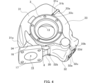
- FIG. 4 is another perspective view showing the turbine housing together with the cover.
- FIG. 1 is a schematic cross-sectional view showing the turbocharger TC according to the embodiment.
- the supercharger TC is applied to an engine.
- the supercharger TC includes a housing 1 , a shaft 7 , a turbine impeller 8 and a compressor impeller 9 .
- the turbine impeller 8 and the compressor impeller 9 rotate integrally with the shaft 7. Therefore, the central axial direction, radial direction and circumferential direction of the shaft 7 are common to the turbine impeller 8 and the compressor impeller 9 .
- the central axial, radial and circumferential directions of these shafts 7, turbine impeller 8 and compressor impeller 9 are simply referred to as "central axial”, “radial” and “circular” respectively, unless otherwise indicated. may be referred to as "circumferential".
- the housing 1 includes a bearing housing 2, a turbine housing 3 and a compressor housing 4.
- One end of the bearing housing 2 is connected to the turbine housing 3 in the central axis direction by a fastening mechanism 21a such as a G coupling.
- a fastening mechanism 21a such as a G coupling.
- the other end of the bearing housing 2 is connected to the compressor housing 4 by a fastening mechanism 21b such as a fastening bolt.
- the bearing housing 2, turbine housing 3 and compressor housing 4 are made of cast iron.
- covers 31, 32 , 33 are attached to the turbine housing 3 .
- cover 33 is not shown in FIG.
- covers 31, 32, 33 may also be referred to as "insulator covers”.
- the covers 31 , 32 accommodate thermal insulation 41 , 42 between the covers 31 , 32 and the outer surface 30 of the turbine housing 3 . Details of the covers 31, 32, and 33 will be described later.
- the bearing housing 2 includes bearing holes 22 .
- the bearing hole 22 extends in the center axis direction inside the bearing housing 2 .
- the bearing hole 22 accommodates a pair of rolling bearings 50,60.
- Rolling bearings 50 and 60 rotatably support shaft 7 .
- a pair of rolling bearings 50 and 60 are spaced apart from each other in the central axis direction.
- a turbine impeller 8 is provided at a first end of the shaft 7 in the central axis direction. Turbine impeller 8 rotates integrally with shaft 7 .
- a turbine impeller 8 is rotatably housed in the turbine housing 3 .
- a compressor impeller 9 is provided at a second end of the shaft 7 opposite to the first end in the central axis direction. The compressor impeller 9 rotates together with the shaft 7 .
- a compressor impeller 9 is rotatably housed in the compressor housing 4 .
- the compressor housing 4 includes an air intake 10 at the end opposite to the bearing housing 2 in the central axis direction.
- the intake port 10 is connected to an air cleaner (not shown).
- Bearing housing 2 and compressor housing 4 define a diffuser flow path 11 therebetween.
- the diffuser flow path 11 expands from the inner side to the outer side in the radial direction.
- the diffuser channel 11 has an annular shape.
- the diffuser flow path 11 communicates with the intake port 10 via the compressor impeller 9 .
- the compressor housing 4 includes a compressor scroll flow path 12.
- the compressor scroll channel 12 is located radially outside the diffuser channel 11 .
- the compressor scroll channel 12 communicates with the diffuser channel 11 . Further, the compressor scroll flow path 12 communicates with an intake port of an engine (not shown).
- the turbine housing 3 includes a discharge port 13 at the end opposite to the bearing housing 2 in the center axis direction.
- the discharge port 13 is connected to an exhaust gas purification device (not shown).
- Turbine housing 3 includes a connecting channel 14 .
- the connecting channel 14 expands from the inner side to the outer side in the radial direction.
- the connecting channel 14 has an annular shape.
- the connection flow path 14 communicates with the discharge port 13 via the turbine impeller 8 .
- the turbine housing 3 includes a turbine scroll passage 15.
- the turbine scroll channel 15 is located radially outside the connecting channel 14 .
- the turbine scroll channel 15 communicates with the connecting channel 14 .
- the turbine scroll passage 15 communicates with a gas inlet (not shown).
- the gas inlet receives exhaust gas discharged from an exhaust manifold of an engine (not shown).
- the exhaust gas is guided from the gas inlet to the turbine scroll passage 15 and then to the discharge port 13 via the connecting passage 14 and the turbine impeller 8 .
- the exhaust gases rotate the turbine impeller 8 while passing through the spaces between the blades of the turbine impeller 8 .
- the rotational force of turbine impeller 8 is transmitted to compressor impeller 9 via shaft 7 .
- the air is pressurized as described above.
- pressurized air is directed to the intake of the engine.
- FIG. 2 is a perspective view showing the turbine housing 3 together with the covers 31 , 32 , 33 and shows the inside of the turbine housing 3 , that is, the side facing the bearing housing 2 .
- 3 is a perspective view showing the turbine housing 3 without the covers 31, 32, 33, showing the turbine housing 3 from the same direction as in FIG.
- a plurality of covers 31, 32, 33 are attached to the turbine housing 3 as described above.
- Three covers 31 , 32 , 33 are attached to the turbine housing 3 in this embodiment. More or less than three covers may be attached to the turbine housing 3 in other embodiments.
- the covers 31, 32, 33 surround the turbine housing 3 in the circumferential direction. Specifically, the covers 31 , 32 , 33 enclose the turbine housing 3 along the contour of the turbine housing 3 that is furthest from the central axis in the radial direction.
- the covers 31, 32, 33 are divided from each other in the circumferential direction. In other embodiments, the covers may be split from one another, for example along the central axis.
- each of the covers 31, 32, 33 has a space between the outer surface 30 of the turbine housing 3 and each of the covers 31, 32, 33.
- the cover 33 is not shown in FIG. 1 as described above.
- the cover 31 accommodates thermal insulation 41 in the space between the cover 31 and the outer surface 30 of the turbine housing 3 .
- the cover 32 also accommodates thermal insulation 42 in the space between the cover 32 and the outer surface 30 of the turbine housing 3 .
- the cover 33 (FIG. 2) accommodates a heat insulating material 43 (FIG. 3) in the space between the cover 33 and the outer surface 30 of the turbine housing 3.
- the heat insulators 41, 42, 43 may be made of a material containing silica fibers and a binder, for example.
- the materials of the heat insulators 41, 42, 43 are not limited to these, and other materials may be used.
- the insulation 41 , 42 , 43 may be fixed to the inner surfaces of the covers 31 , 32 , 33 or to the outer surface 30 of the turbine housing 3 .
- FIG. 4 is a perspective view showing the turbine housing 3 together with the covers 31, 32, 33 as seen from another direction, showing the outside of the turbine housing 3.
- FIG. 4 shows the turbine housing 3 from the opposite direction to FIG.
- the first cover 31 includes a first end 31a and a second end 31b in the circumferential direction.
- the second cover 32 includes a first end 32a and a second end 32b in the circumferential direction.
- the third cover 33 includes a first end 33a and a second end 33b in the circumferential direction.
- the first cover 31 includes a flange 31c at the second end 31b.
- the flange 31c protrudes away from the outer surface 30 of the turbine housing 3 and is bent substantially perpendicularly to the direction of protrusion.
- a flange 31 c is provided along the edge of the second end 31 b of the first cover 31 .
- the third cover 33 also includes a flange 33c at the first end 33a.
- Flange 33c has a shape corresponding to flange 31c. That is, the flange 33c protrudes away from the outer surface 30 of the turbine housing 3 and is bent substantially perpendicularly to the protruding direction.
- a flange 33 c is provided along the edge of the first end 33 a of the third cover 33 .
- the first cover 31 and the third cover 33 are made of the same metal such as stainless steel, and the flanges 31c and 33c are fixed to each other by welding.
- Fixing means for the flanges 31c and 33c is not limited to welding, and other fixing means such as bolts, wires or hooks may be used.
- the second cover 32 includes a flange 32c at the first end 32a.
- the flange 32c protrudes away from the outer surface 30 of the turbine housing 3 and is bent generally perpendicular to the direction of protrusion.
- a flange 32 c is provided along the edge of the first end 32 a of the second cover 32 .
- the third cover 33 also includes a flange 33d at the second end 33b.
- Flange 33d has a shape corresponding to flange 32c. That is, the flange 33d protrudes away from the outer surface 30 of the turbine housing 3 and is bent substantially perpendicularly to the protruding direction.
- a flange 33 d is provided along the edge of the second end 33 b of the third cover 33 .
- the second cover 32 and the third cover 33 are made of the same metal such as stainless steel, and the flanges 32c and 33d are fixed to each other by welding.
- Fixing means for the flanges 32c and 33d is not limited to welding, and other fixing means may be used.
- turbine housing 3 includes scroll walls 16 that define turbine scroll passages 15 .
- the scroll wall 16 is also provided with a flange 17 .
- the first cover 31 and the second cover 32 are circumferentially spaced between the first end 31a of the first cover 31 and the second end 32b of the second cover 32. It has a gap g.
- the first end 31a of the first cover 31 and the second end 32b of the second cover 32 are indirectly connected to each other by a connecting piece 34 bridging the gap g.
- each connecting piece 34 is connected to the first end 31 a of the first cover 31 and the other end is connected to the second end 32 b of the second cover 32 .
- the connecting piece 34 is made of the same metal as the first cover 31 and the second cover 32, such as stainless steel, and is fixed to the first cover 31 and the second cover 32 by welding.
- the fixing means of the connecting piece 34 to the first cover 31 and the second cover 32 is not limited to welding, and other fixing means such as bolts, wires or hooks may be used.
- the connecting piece 34 is arranged directly on the outer surface 30 of the turbine housing 3 . That is, the connecting piece 34 does not accommodate the heat insulating material 41 . From another point of view, the connecting piece 34 is only used to bridge the first cover 31 and the second cover 32 . For example, the connecting piece 34 may contact the outer surface 30 of the turbine housing 3 , may be non-contacting with the outer surface 30 , or may partially contact the outer surface 30 .
- the covers 31 , 32 , 33 and the connecting piece 34 are circumferentially connected to each other to define a closed loop around the turbine housing 3 . Therefore, the covers 31 , 32 , 33 and the connecting piece 34 can be tightly wound around the turbine housing 3 , whereby the covers 31 , 32 , 33 are more firmly fixed to the turbine housing 3 .
- each of the covers 31 , 32 , 33 is attached to the outer surface 30 of the turbine housing 3 by spot welding in addition to being wrapped around the turbine housing 3 by the covers 31 , 32 , 33 and the connecting piece 34 . fixed directly.
- the connecting piece 34 may also be fixed directly to the outer surface 30 of the turbine housing 3 by spot welding as well.
- the outer surface 30 of the turbine housing 3 includes a casting surface.
- the covers 31, 32, 33 and the connecting piece 34 define a closed loop around the turbine housing 3, so even if the spot welds to the casting surface are broken, the covers 31, 32, 33 and The connecting piece 34 is subsequently fixed to the turbine housing 3 .
- the turbocharger TC as described above includes a turbine housing 3 and a plurality of covers 31, 32, 33 each surrounding at least a portion of the outer surface 30 of the turbine housing 3.
- the plurality of covers 31, 32, 33 are , at least a first cover 31 and a second cover 32 , each of the plurality of covers 31 , 32 , 33 having thermal insulation 41 , 33 between the cover 31 , 32 , 33 and the outer surface 30 of the turbine housing 3 .
- a plurality of covers 31, 32, 33 housing 42, 43, a connecting piece 34 positioned directly on the outer surface 30 of the turbine housing 3 and connecting the first cover 31 and the second cover 32; Prepare.
- the coupling used only for coupling can be used.
- a piece 34 can bridge the first cover 31 and the second cover 32 . Therefore, for example, even if the shape of the turbine housing 3 is complicated, a plurality of covers can be connected by the connecting piece 34 . Therefore, the attachment of the covers 31, 32, 33 to the turbine housing 3 can be improved.
- the first cover 31, the second cover 32 and the connecting piece 34 are made of the same metal. Therefore, even if the supercharger TC is repeatedly exposed to thermal stress, the first cover 31, the second cover 32 and the connecting piece 34 can follow the thermal expansion. Therefore, loosening of the attachment of the first cover 31 , the second cover 32 and the connecting piece 34 to the turbine housing 3 can be suppressed. Moreover, when the first cover 31, the second cover 32 and the connecting piece 34 are connected by welding, the welding strength can be improved.
- a plurality of covers 31, 32, 33 are arranged along the circumferential direction of the shaft 7 of the supercharger TC, and the first cover 31 and the second cover 32 are A connecting piece 34 is disposed in the gap g and a closed loop is defined around the turbine housing 3 by the plurality of covers 31 , 32 , 33 and the connecting piece 34 with a circumferential gap g therebetween.
- the covers 31 , 32 , 33 and the connecting piece 34 can be tightly wound around the turbine housing 3 , whereby the covers 31 , 32 , 33 are more firmly fixed to the turbine housing 3 . be done.
- the connecting piece 34 is applied to the covers 31, 32 attached to the turbine housing 3. Additionally or alternatively, however, in other embodiments the connecting piece may be applied to a cover, not shown, which is attached to the compressor housing 4 . In this case, insulation is accommodated between the outer surface of the compressor housing 4 and the cover, while the connecting piece is arranged directly on the outer surface of the compressor housing 4 .
Abstract
This supercharger comprises: a housing 3; a plurality of covers 31, 32, 33 that each surround at least part of an outer surface 30 of the housing 3, the plurality of covers 31, 32, 33 including at least a first cover 31 and a second cover 32, and each of the plurality of covers 31, 32, 33 accommodating a heat insulation material between the covers 31, 32, 33 and the outer surface 30 of the housing 3; and a linking piece 34 that is disposed directly on the outer surface 30 of the housing 3 and that links the first cover 31 and the second cover 32.
Description
本開示は、過給機に関する。本出願は2021年8月26日に提出された日本特許出願第2021-138212号に基づく優先権の利益を主張するものであり、その内容は本出願に援用される。
This disclosure relates to turbochargers. This application claims the benefit of priority based on Japanese Patent Application No. 2021-138212 filed on August 26, 2021, the content of which is incorporated herein by reference.
過給機は、排気ガスの温度低下を抑制するために、断熱材を備える場合がある。例えば、特許文献1に開示される過給機は、過給機のタービンハウジングを囲むカバーと、タービンハウジングの外面との間に断熱材を備える。カバーは、概ね円筒形状を有しており、軸線方向に沿って2つの部分に分割される。2つの部分は、溶接によって互いに結合される。
The turbocharger may be equipped with a heat insulating material to suppress the temperature drop of the exhaust gas. For example, a supercharger disclosed in Patent Document 1 includes a heat insulating material between a cover surrounding a turbine housing of the supercharger and an outer surface of the turbine housing. The cover has a generally cylindrical shape and is axially divided into two parts. The two parts are joined together by welding.
過給機のハウジングは、様々な形状を有し得る。したがって、ハウジングの形状によっては、断熱材を収容するカバーをハウジングに対して取り付けることが困難な場合がある。したがって、ハウジングに対するカバーの取付を改良することができる技術の開発が望まれる。
The turbocharger housing can have various shapes. Therefore, depending on the shape of the housing, it may be difficult to attach the cover containing the heat insulating material to the housing. Therefore, it would be desirable to develop a technique that could improve the attachment of the cover to the housing.
本開示は、上記のような課題を考慮して、ハウジングに対するカバーの取付を改良することができる、過給機を提供することを目的とする。
An object of the present disclosure is to provide a supercharger capable of improving attachment of the cover to the housing in consideration of the above problems.
本開示の一態様に係る過給機は、ハウジングと、各々がハウジングの外面の少なくとも一部を囲う複数のカバーであって、複数のカバーは、少なくとも第1のカバーおよび第2のカバーを含み、複数のカバーの各々は、当該カバーとハウジングの外面との間に断熱材を収容する、複数のカバーと、ハウジングの外面上に直接的に配置され、第1のカバーおよび第2のカバーを連結する連結ピースと、を備える。
A turbocharger according to one aspect of the present disclosure includes a housing and a plurality of covers each surrounding at least a portion of an outer surface of the housing, the plurality of covers including at least a first cover and a second cover. , a plurality of covers, each of the plurality of covers, disposed directly on the outer surface of the housing, each containing a thermal insulator between the cover and the outer surface of the housing, the first cover and the second cover; and a connecting piece that connects.
第1のカバー、第2のカバーおよび連結ピースは、同一の金属で形成されてもよい。
The first cover, the second cover and the connecting piece may be made of the same metal.
複数のカバーは、過給機のシャフトの円周方向に沿って配置されてもよく、第1のカバーおよび第2のカバーは、それらの間に円周方向の隙間を有してもよく、連結ピースは、円周方向の隙間に配置され、複数のカバーおよび連結ピースによって、ハウジングの周りに閉ループが規定されてもよい。
The plurality of covers may be arranged along a circumferential direction of the shaft of the supercharger, the first cover and the second cover may have a circumferential gap therebetween; A connecting piece may be disposed in the circumferential gap and a closed loop defined around the housing by the plurality of covers and connecting pieces.
本開示によれば、ハウジングに対するカバーの取付を改良することができる。
According to the present disclosure, attachment of the cover to the housing can be improved.
以下に添付図面を参照しながら、本開示の実施形態について詳細に説明する。かかる実施形態に示す具体的な寸法、材料および数値等は、理解を容易とするための例示にすぎず、特に断る場合を除き、本開示を限定するものではない。なお、本明細書および図面において、実質的に同一の機能、構成を有する要素については、同一の符号を付することにより重複説明を省略し、また本開示に直接関係のない要素は図示を省略する。
Embodiments of the present disclosure will be described in detail below with reference to the accompanying drawings. Specific dimensions, materials, numerical values, and the like shown in such embodiments are merely examples for facilitating understanding, and do not limit the present disclosure unless otherwise specified. In the present specification and drawings, elements having substantially the same function and configuration are given the same reference numerals to omit redundant description, and elements that are not directly related to the present disclosure are omitted from the drawings. do.
図1は、実施形態に係る過給機TCを示す概略的な断面図である。例えば、過給機TCは、エンジンに適用される。過給機TCは、ハウジング1と、シャフト7と、タービンインペラ8と、コンプレッサインペラ9と、を備える。
FIG. 1 is a schematic cross-sectional view showing the turbocharger TC according to the embodiment. For example, the supercharger TC is applied to an engine. The supercharger TC includes a housing 1 , a shaft 7 , a turbine impeller 8 and a compressor impeller 9 .
後述するように、タービンインペラ8およびコンプレッサインペラ9は、シャフト7と一体的に回転する。したがって、シャフト7の中心軸線方向、径方向および円周方向は、タービンインペラ8およびコンプレッサインペラ9に共通である。本開示では、これらシャフト7、タービンインペラ8およびコンプレッサインペラ9の中心軸線方向、径方向および円周方向は、他に指示が無い限り、それぞれ単に「中心軸線方向」、「径方向」および「円周方向」と称され得る。
As will be described later, the turbine impeller 8 and the compressor impeller 9 rotate integrally with the shaft 7. Therefore, the central axial direction, radial direction and circumferential direction of the shaft 7 are common to the turbine impeller 8 and the compressor impeller 9 . In this disclosure, the central axial, radial and circumferential directions of these shafts 7, turbine impeller 8 and compressor impeller 9 are simply referred to as "central axial", "radial" and "circular" respectively, unless otherwise indicated. may be referred to as "circumferential".
ハウジング1は、ベアリングハウジング2と、タービンハウジング3と、コンプレッサハウジング4と、を含む。中心軸線方向において、ベアリングハウジング2の一方の端部は、Gカップリング等の締結機構21aによってタービンハウジング3に連結される。中心軸線方向において、ベアリングハウジング2の他方の端部は、締結ボルト等の締結機構21bによってコンプレッサハウジング4に連結される。例えば、ベアリングハウジング2、タービンハウジング3およびコンプレッサハウジング4は、鋳鉄によって形成される。
The housing 1 includes a bearing housing 2, a turbine housing 3 and a compressor housing 4. One end of the bearing housing 2 is connected to the turbine housing 3 in the central axis direction by a fastening mechanism 21a such as a G coupling. In the central axis direction, the other end of the bearing housing 2 is connected to the compressor housing 4 by a fastening mechanism 21b such as a fastening bolt. For example, the bearing housing 2, turbine housing 3 and compressor housing 4 are made of cast iron.
タービンハウジング3には、複数のカバー31,32,33が取り付けられる。なお、図1には、カバー33は示されていない。本開示において、カバー31,32,33は、「インシュレータカバー」とも称され得る。カバー31,32は、カバー31,32とタービンハウジング3の外面30との間に、断熱材41,42を収容する。カバー31,32,33については、詳しくは後述する。
A plurality of covers 31 , 32 , 33 are attached to the turbine housing 3 . Note that the cover 33 is not shown in FIG. In the present disclosure, covers 31, 32, 33 may also be referred to as "insulator covers". The covers 31 , 32 accommodate thermal insulation 41 , 42 between the covers 31 , 32 and the outer surface 30 of the turbine housing 3 . Details of the covers 31, 32, and 33 will be described later.
ベアリングハウジング2は、軸受孔22を含む。軸受孔22は、ベアリングハウジング2内を中心軸線方向に延在する。軸受孔22は、一対の転がり軸受50,60を収容する。転がり軸受50,60は、シャフト7を回転可能に支持する。一対の転がり軸受50,60は、中心軸線方向に互いに離間する。
The bearing housing 2 includes bearing holes 22 . The bearing hole 22 extends in the center axis direction inside the bearing housing 2 . The bearing hole 22 accommodates a pair of rolling bearings 50,60. Rolling bearings 50 and 60 rotatably support shaft 7 . A pair of rolling bearings 50 and 60 are spaced apart from each other in the central axis direction.
中心軸線方向において、シャフト7の第1の端部には、タービンインペラ8が設けられる。タービンインペラ8は、シャフト7と一体的に回転する。タービンインペラ8は、タービンハウジング3に回転可能に収容される。中心軸線方向において、第1の端部とは反対側のシャフト7の第2の端部には、コンプレッサインペラ9が設けられる。コンプレッサインペラ9は、シャフト7と一体的に回転する。コンプレッサインペラ9は、コンプレッサハウジング4に回転可能に収容される。
A turbine impeller 8 is provided at a first end of the shaft 7 in the central axis direction. Turbine impeller 8 rotates integrally with shaft 7 . A turbine impeller 8 is rotatably housed in the turbine housing 3 . A compressor impeller 9 is provided at a second end of the shaft 7 opposite to the first end in the central axis direction. The compressor impeller 9 rotates together with the shaft 7 . A compressor impeller 9 is rotatably housed in the compressor housing 4 .
コンプレッサハウジング4は、中心軸線方向においてベアリングハウジング2と反対側の端部に、吸気口10を含む。吸気口10は、不図示のエアクリーナに接続される。ベアリングハウジング2およびコンプレッサハウジング4は、それらの間にディフューザ流路11を規定する。ディフューザ流路11は、径方向の内側から外側に向けて拡がる。ディフューザ流路11は、環状形状を有する。ディフューザ流路11は、コンプレッサインペラ9を介して吸気口10に連通する。
The compressor housing 4 includes an air intake 10 at the end opposite to the bearing housing 2 in the central axis direction. The intake port 10 is connected to an air cleaner (not shown). Bearing housing 2 and compressor housing 4 define a diffuser flow path 11 therebetween. The diffuser flow path 11 expands from the inner side to the outer side in the radial direction. The diffuser channel 11 has an annular shape. The diffuser flow path 11 communicates with the intake port 10 via the compressor impeller 9 .
コンプレッサハウジング4は、コンプレッサスクロール流路12を含む。コンプレッサスクロール流路12は、ディフューザ流路11に対して径方向外側に位置する。コンプレッサスクロール流路12は、ディフューザ流路11と連通する。また、コンプレッサスクロール流路12は、不図示のエンジンの吸気口と連通する。
The compressor housing 4 includes a compressor scroll flow path 12. The compressor scroll channel 12 is located radially outside the diffuser channel 11 . The compressor scroll channel 12 communicates with the diffuser channel 11 . Further, the compressor scroll flow path 12 communicates with an intake port of an engine (not shown).
上記のようなコンプレッサハウジング4では、コンプレッサインペラ9が回転すると、吸気口10からコンプレッサハウジング4内に空気が吸気される。吸気は、コンプレッサインペラ9の翼の間の空間を通る間に、遠心力によって増速される。増速された空気は、ディフューザ流路11およびコンプレッサスクロール流路12で加圧される。加圧された空気は、不図示の吐出口から流出し、エンジンの吸気口に導かれる。
In the compressor housing 4 as described above, when the compressor impeller 9 rotates, air is drawn into the compressor housing 4 through the intake port 10 . The intake air is accelerated by centrifugal force while passing through the spaces between the blades of the compressor impeller 9 . The accelerated air is pressurized in diffuser passage 11 and compressor scroll passage 12 . The pressurized air flows out from a discharge port (not shown) and is led to the intake port of the engine.
タービンハウジング3は、中心軸線方向においてベアリングハウジング2と反対側の端部に、吐出口13を含む。吐出口13は、不図示の排気ガス浄化装置に接続される。タービンハウジング3は、連結流路14を含む。連結流路14は、径方向の内側から外側に向けて拡がる。連結流路14は、環状形状を有する。連結流路14は、タービンインペラ8を介して吐出口13に連通する。
The turbine housing 3 includes a discharge port 13 at the end opposite to the bearing housing 2 in the center axis direction. The discharge port 13 is connected to an exhaust gas purification device (not shown). Turbine housing 3 includes a connecting channel 14 . The connecting channel 14 expands from the inner side to the outer side in the radial direction. The connecting channel 14 has an annular shape. The connection flow path 14 communicates with the discharge port 13 via the turbine impeller 8 .
タービンハウジング3は、タービンスクロール流路15を含む。タービンスクロール流路15は、連結流路14に対して径方向の外側に位置する。タービンスクロール流路15は、連結流路14と連通する。また、タービンスクロール流路15は、不図示のガス流入口と連通する。ガス流入口は、不図示のエンジンの排気マニホールドから排出される排気ガスを受け入れる。
The turbine housing 3 includes a turbine scroll passage 15. The turbine scroll channel 15 is located radially outside the connecting channel 14 . The turbine scroll channel 15 communicates with the connecting channel 14 . Further, the turbine scroll passage 15 communicates with a gas inlet (not shown). The gas inlet receives exhaust gas discharged from an exhaust manifold of an engine (not shown).
上記のようなタービンハウジング3では、排気ガスは、ガス流入口からタービンスクロール流路15に導かれ、さらに、連結流路14およびタービンインペラ8を介して吐出口13に導かれる。排気ガスは、タービンインペラ8の翼の間の空間を通る間に、タービンインペラ8を回転させる。タービンインペラ8の回転力は、シャフト7を介してコンプレッサインペラ9に伝達される。コンプレッサインペラ9が回転すると、上記のとおりに空気が加圧される。こうして、加圧された空気がエンジンの吸気口に導かれる。
In the turbine housing 3 as described above, the exhaust gas is guided from the gas inlet to the turbine scroll passage 15 and then to the discharge port 13 via the connecting passage 14 and the turbine impeller 8 . The exhaust gases rotate the turbine impeller 8 while passing through the spaces between the blades of the turbine impeller 8 . The rotational force of turbine impeller 8 is transmitted to compressor impeller 9 via shaft 7 . As the compressor impeller 9 rotates, the air is pressurized as described above. Thus, pressurized air is directed to the intake of the engine.
続いて、カバー31,32,33について説明する。
Next, the covers 31, 32, 33 will be explained.
図2は、カバー31,32,33と共にタービンハウジング3を示す斜視図であり、タービンハウジング3の内側、すなわち、ベアリングハウジング2と対向する側を示す。図3は、カバー31,32,33無しにタービンハウジング3を示す斜視図であり、図2と同じ方向からタービンハウジング3を示す。
FIG. 2 is a perspective view showing the turbine housing 3 together with the covers 31 , 32 , 33 and shows the inside of the turbine housing 3 , that is, the side facing the bearing housing 2 . 3 is a perspective view showing the turbine housing 3 without the covers 31, 32, 33, showing the turbine housing 3 from the same direction as in FIG.
図2を参照して、上記のように、タービンハウジング3には、複数のカバー31,32,33が取り付けられる。本実施形態では、3つのカバー31,32,33が、タービンハウジング3に取り付けられる。他の実施形態では、3つより多いまたは3つより少ないカバーが、タービンハウジング3に取り付けられてもよい。
With reference to FIG. 2, a plurality of covers 31, 32, 33 are attached to the turbine housing 3 as described above. Three covers 31 , 32 , 33 are attached to the turbine housing 3 in this embodiment. More or less than three covers may be attached to the turbine housing 3 in other embodiments.
カバー31,32,33は、円周方向にタービンハウジング3を囲う。具体的には、カバー31,32,33は、径方向において中心軸線から最も離れたタービンハウジング3の輪郭に沿って、タービンハウジング3を囲う。カバー31,32,33は、円周方向に互いに分割されている。他の実施形態では、カバーは、例えば、中心軸線方向に互いに分割されていてもよい。
The covers 31, 32, 33 surround the turbine housing 3 in the circumferential direction. Specifically, the covers 31 , 32 , 33 enclose the turbine housing 3 along the contour of the turbine housing 3 that is furthest from the central axis in the radial direction. The covers 31, 32, 33 are divided from each other in the circumferential direction. In other embodiments, the covers may be split from one another, for example along the central axis.
図1を参照して、カバー31,32,33の各々は、タービンハウジング3の外面30と各カバー31,32,33との間に、空間を有する。なお、上記のように、図1には、カバー33は示されていない。カバー31は、カバー31とタービンハウジング3の外面30との間の空間に、断熱材41を収容する。また、カバー32は、カバー32とタービンハウジング3の外面30との間の空間に、断熱材42を収容する。また、図2および図3を参照して、カバー33(図2)は、カバー33とタービンハウジング3の外面30との間の空間に、断熱材43(図3)を収容する。断熱材41,42,43は、例えば、シリカ繊維およびバインダを含む材料によって形成されてもよい。断熱材41,42,43の材料はこれに限定されず、他の材料が使用されてもよい。例えば、断熱材41,42,43は、カバー31,32,33の内面に固定されてもよく、または、タービンハウジング3の外面30に固定されてもよい。
With reference to FIG. 1, each of the covers 31, 32, 33 has a space between the outer surface 30 of the turbine housing 3 and each of the covers 31, 32, 33. Note that the cover 33 is not shown in FIG. 1 as described above. The cover 31 accommodates thermal insulation 41 in the space between the cover 31 and the outer surface 30 of the turbine housing 3 . The cover 32 also accommodates thermal insulation 42 in the space between the cover 32 and the outer surface 30 of the turbine housing 3 . 2 and 3, the cover 33 (FIG. 2) accommodates a heat insulating material 43 (FIG. 3) in the space between the cover 33 and the outer surface 30 of the turbine housing 3. As shown in FIG. The heat insulators 41, 42, 43 may be made of a material containing silica fibers and a binder, for example. The materials of the heat insulators 41, 42, 43 are not limited to these, and other materials may be used. For example, the insulation 41 , 42 , 43 may be fixed to the inner surfaces of the covers 31 , 32 , 33 or to the outer surface 30 of the turbine housing 3 .
図4は、カバー31,32,33と共にタービンハウジング3を示す別方向から見た斜視図であり、タービンハウジング3の外側を示す。すなわち、図4は、図2と反対の方向からタービンハウジング3を示す。第1のカバー31は、円周方向において第1の端部31aおよび第2の端部31bを含む。第2のカバー32は、円周方向において第1の端部32aおよび第2の端部32bを含む。第3のカバー33は、円周方向において第1の端部33aおよび第2の端部33bを含む。
FIG. 4 is a perspective view showing the turbine housing 3 together with the covers 31, 32, 33 as seen from another direction, showing the outside of the turbine housing 3. FIG. 4 shows the turbine housing 3 from the opposite direction to FIG. The first cover 31 includes a first end 31a and a second end 31b in the circumferential direction. The second cover 32 includes a first end 32a and a second end 32b in the circumferential direction. The third cover 33 includes a first end 33a and a second end 33b in the circumferential direction.
第1のカバー31は、第2の端部31bにフランジ31cを含む。フランジ31cは、タービンハウジング3の外面30から離間するように突出し、さらに、突出方向に概ね直角に曲げられている。例えば、フランジ31cは、第1のカバー31の第2の端部31bの縁部に沿って設けられる。また、第3のカバー33は、第1の端部33aにフランジ33cを含む。フランジ33cは、フランジ31cに対応する形状を有する。すなわち、フランジ33cは、タービンハウジング3の外面30から離間するように突出し、さらに、突出方向に概ね直角に曲げられている。例えば、フランジ33cは、第3のカバー33の第1の端部33aの縁部に沿って設けられる。本実施形態では、第1のカバー31および第3のカバー33は、同じ金属、例えばステンレスによって形成されており、フランジ31cおよびフランジ33cは、溶接によって互いに固定される。フランジ31cおよびフランジ33cの固定手段は溶接に限らず、例えば、ボルト、針金またはフック等の他の固定手段が用いられてもよい。
The first cover 31 includes a flange 31c at the second end 31b. The flange 31c protrudes away from the outer surface 30 of the turbine housing 3 and is bent substantially perpendicularly to the direction of protrusion. For example, a flange 31 c is provided along the edge of the second end 31 b of the first cover 31 . The third cover 33 also includes a flange 33c at the first end 33a. Flange 33c has a shape corresponding to flange 31c. That is, the flange 33c protrudes away from the outer surface 30 of the turbine housing 3 and is bent substantially perpendicularly to the protruding direction. For example, a flange 33 c is provided along the edge of the first end 33 a of the third cover 33 . In this embodiment, the first cover 31 and the third cover 33 are made of the same metal such as stainless steel, and the flanges 31c and 33c are fixed to each other by welding. Fixing means for the flanges 31c and 33c is not limited to welding, and other fixing means such as bolts, wires or hooks may be used.
第2のカバー32は、第1の端部32aにフランジ32cを含む。フランジ32cは、タービンハウジング3の外面30から離間するように突出し、さらに、突出方向に概ね直角に曲げられている。例えば、フランジ32cは、第2のカバー32の第1の端部32aの縁部に沿って設けられる。また、第3のカバー33は、第2の端部33bにフランジ33dを含む。フランジ33dは、フランジ32cに対応する形状を有する。すなわち、フランジ33dは、タービンハウジング3の外面30から離間するように突出し、さらに、突出方向に概ね直角に曲げられている。例えば、フランジ33dは、第3のカバー33の第2の端部33bの縁部に沿って設けられる。本実施形態では、第2のカバー32および第3のカバー33は、同じ金属、例えばステンレスによって形成されており、フランジ32cおよびフランジ33dは、溶接によって互いに固定される。フランジ32cおよびフランジ33dの固定手段は溶接に限らず、他の固定手段が用いられてもよい。
The second cover 32 includes a flange 32c at the first end 32a. The flange 32c protrudes away from the outer surface 30 of the turbine housing 3 and is bent generally perpendicular to the direction of protrusion. For example, a flange 32 c is provided along the edge of the first end 32 a of the second cover 32 . The third cover 33 also includes a flange 33d at the second end 33b. Flange 33d has a shape corresponding to flange 32c. That is, the flange 33d protrudes away from the outer surface 30 of the turbine housing 3 and is bent substantially perpendicularly to the protruding direction. For example, a flange 33 d is provided along the edge of the second end 33 b of the third cover 33 . In this embodiment, the second cover 32 and the third cover 33 are made of the same metal such as stainless steel, and the flanges 32c and 33d are fixed to each other by welding. Fixing means for the flanges 32c and 33d is not limited to welding, and other fixing means may be used.
上記のように、第1のカバー31および第3のカバー33は、円周方向に連続的に配置され、フランジ31cおよびフランジ33cによって直接的に固定される。同様に、第2のカバー32および第3のカバー33は、円周方向に連続的に配置され、フランジ32cおよびフランジ33dによって直接的に固定される。しかしながら、タービンハウジング3は、タービンスクロール流路15を規定するスクロール壁16を含む。また、スクロール壁16には、フランジ17が設けられる。本実施形態では、これらスクロール壁16およびフランジ17の位置に起因して、第1のカバー31および第2のカバー32を円周方向に連続して配置することが困難である。したがって、第1のカバー31および第2のカバー32は、第1のカバー31の第1の端部31aと、第2のカバー32の第2の端部32bとの間に、円周方向に隙間gを有する。第1のカバー31の第1の端部31aと、第2のカバー32の第2の端部32bとは、隙間gを橋渡しする連結ピース34によって、互いに間接的に連結される。
As described above, the first cover 31 and the third cover 33 are arranged continuously in the circumferential direction and directly fixed by the flanges 31c and 33c. Similarly, the second cover 32 and the third cover 33 are arranged continuously in the circumferential direction and directly fixed by the flanges 32c and 33d. However, turbine housing 3 includes scroll walls 16 that define turbine scroll passages 15 . The scroll wall 16 is also provided with a flange 17 . In this embodiment, due to the positions of the scroll wall 16 and the flange 17, it is difficult to arrange the first cover 31 and the second cover 32 continuously in the circumferential direction. Thus, the first cover 31 and the second cover 32 are circumferentially spaced between the first end 31a of the first cover 31 and the second end 32b of the second cover 32. It has a gap g. The first end 31a of the first cover 31 and the second end 32b of the second cover 32 are indirectly connected to each other by a connecting piece 34 bridging the gap g.
図2および図4を参照して、本実施形態では、2つの連結ピース34が使用される。他の実施形態では、1つのみの連結ピース34が使用されてもよく、または、3つ以上の連結ピース34が使用されてもよい。2つの連結ピース34は、中心軸線方向においてタービンハウジング3の両方の面、例えばスクロール壁16の両方の面に、タービンスクロール流路15を挟んで配置される。各連結ピース34の一方の端部は、第1のカバー31の第1の端部31aに連結され、他方の端部は、第2のカバー32の第2の端部32bに連結される。本実施形態では、連結ピース34は、第1のカバー31および第2のカバー32と同じ金属、例えばステンレスによって形成されており、溶接によって第1のカバー31および第2のカバー32に固定される。連結ピース34の第1のカバー31および第2のカバー32への固定手段は溶接に限らず、例えば、ボルト、針金またはフック等の他の固定手段が用いられてもよい。
With reference to FIGS. 2 and 4, two connecting pieces 34 are used in this embodiment. In other embodiments, only one connecting piece 34 may be used, or more than two connecting pieces 34 may be used. The two connecting pieces 34 are arranged on both sides of the turbine housing 3 , for example, on both sides of the scroll wall 16 in the center axis direction, with the turbine scroll flow path 15 interposed therebetween. One end of each connecting piece 34 is connected to the first end 31 a of the first cover 31 and the other end is connected to the second end 32 b of the second cover 32 . In this embodiment, the connecting piece 34 is made of the same metal as the first cover 31 and the second cover 32, such as stainless steel, and is fixed to the first cover 31 and the second cover 32 by welding. . The fixing means of the connecting piece 34 to the first cover 31 and the second cover 32 is not limited to welding, and other fixing means such as bolts, wires or hooks may be used.
連結ピース34は、タービンハウジング3の外面30上に直接的に配置される。すなわち、連結ピース34は、断熱材41を収容しない。別の観点では、連結ピース34は、第1のカバー31および第2のカバー32を橋渡しするためのみに使用される。例えば、連結ピース34は、タービンハウジング3の外面30と接触してもよく、または、外面30と非接触であってもよく、または、外面30と部分的に接触してもよい。
The connecting piece 34 is arranged directly on the outer surface 30 of the turbine housing 3 . That is, the connecting piece 34 does not accommodate the heat insulating material 41 . From another point of view, the connecting piece 34 is only used to bridge the first cover 31 and the second cover 32 . For example, the connecting piece 34 may contact the outer surface 30 of the turbine housing 3 , may be non-contacting with the outer surface 30 , or may partially contact the outer surface 30 .
上記のように、カバー31,32,33および連結ピース34は、円周方向に互いに連結され、タービンハウジング3の周りに閉ループを規定する。したがって、カバー31,32,33および連結ピース34は、タービンハウジング3により強固に巻き付くことができ、これによって、カバー31,32,33は、タービンハウジング3により強固に固定される。
As described above, the covers 31 , 32 , 33 and the connecting piece 34 are circumferentially connected to each other to define a closed loop around the turbine housing 3 . Therefore, the covers 31 , 32 , 33 and the connecting piece 34 can be tightly wound around the turbine housing 3 , whereby the covers 31 , 32 , 33 are more firmly fixed to the turbine housing 3 .
なお、本実施形態では、カバー31,32,33の各々は、上記のカバー31,32,33および連結ピース34によるタービンハウジング3への巻き付きに加えて、スポット溶接によってタービンハウジング3の外面30に直接的に固定される。また、連結ピース34も同様に、スポット溶接によってタービンハウジング3の外面30に直接的に固定されてもよい。しかしながら、タービンハウジング3の外面30は鋳肌を含む。カバー31,32,33が鋳肌にスポット溶接される場合、スポット溶接の強度は低くなる場合がある。したがって、過給機TCが長期の使用によって繰り返し熱応力に晒されると、スポット溶接は、タービンハウジング3の外面30から剥がれる可能性がある。しかしながら、本実施形態では、カバー31,32,33および連結ピース34が、タービンハウジング3の周りに閉ループを規定するため、鋳肌へのスポット溶接が剥がれる場合にも、カバー31,32,33および連結ピース34は、引き続きタービンハウジング3に固定される。
In this embodiment, each of the covers 31 , 32 , 33 is attached to the outer surface 30 of the turbine housing 3 by spot welding in addition to being wrapped around the turbine housing 3 by the covers 31 , 32 , 33 and the connecting piece 34 . fixed directly. The connecting piece 34 may also be fixed directly to the outer surface 30 of the turbine housing 3 by spot welding as well. However, the outer surface 30 of the turbine housing 3 includes a casting surface. When the covers 31, 32, 33 are spot-welded to the casting surface, the spot-welding strength may be low. Therefore, when the supercharger TC is subjected to repeated thermal stresses due to long-term use, the spot welds may delaminate from the outer surface 30 of the turbine housing 3 . However, in this embodiment, the covers 31, 32, 33 and the connecting piece 34 define a closed loop around the turbine housing 3, so even if the spot welds to the casting surface are broken, the covers 31, 32, 33 and The connecting piece 34 is subsequently fixed to the turbine housing 3 .
以上のような過給機TCは、タービンハウジング3と、各々がタービンハウジング3の外面30の少なくとも一部を囲う複数のカバー31,32,33であって、複数のカバー31,32,33は、少なくとも第1のカバー31および第2のカバー32を含み、複数のカバー31,32,33の各々は、当該カバー31,32,33とタービンハウジング3の外面30との間に断熱材41,42,43を収容する、複数のカバー31,32,33と、タービンハウジング3の外面30上に直接的に配置され、第1のカバー31および第2のカバー32を連結する連結ピース34と、を備える。このような構成によれば、タービンハウジング3の形状に起因して、第1のカバー31および第2のカバー32を連続的に配置できない場合であっても、連結のためのみに使用される連結ピース34によって、第1のカバー31および第2のカバー32を橋渡しすることができる。したがって、例えば、タービンハウジング3の形状が複雑な場合であっても、連結ピース34によって、複数のカバーをつなぎ留めることができる。よって、タービンハウジング3に対するカバー31,32,33の取付を改良することができる。
The turbocharger TC as described above includes a turbine housing 3 and a plurality of covers 31, 32, 33 each surrounding at least a portion of the outer surface 30 of the turbine housing 3. The plurality of covers 31, 32, 33 are , at least a first cover 31 and a second cover 32 , each of the plurality of covers 31 , 32 , 33 having thermal insulation 41 , 33 between the cover 31 , 32 , 33 and the outer surface 30 of the turbine housing 3 . a plurality of covers 31, 32, 33 housing 42, 43, a connecting piece 34 positioned directly on the outer surface 30 of the turbine housing 3 and connecting the first cover 31 and the second cover 32; Prepare. According to such a configuration, even if the first cover 31 and the second cover 32 cannot be arranged continuously due to the shape of the turbine housing 3, the coupling used only for coupling can be used. A piece 34 can bridge the first cover 31 and the second cover 32 . Therefore, for example, even if the shape of the turbine housing 3 is complicated, a plurality of covers can be connected by the connecting piece 34 . Therefore, the attachment of the covers 31, 32, 33 to the turbine housing 3 can be improved.
また、過給機TCでは、第1のカバー31、第2のカバー32および連結ピース34は、同一の金属で形成される。したがって、過給機TCが繰り返し熱応力に晒されても、第1のカバー31、第2のカバー32および連結ピース34は、熱膨張に追従することができる。よって、第1のカバー31、第2のカバー32および連結ピース34のタービンハウジング3への取付が緩むことを抑制することができる。また、第1のカバー31、第2のカバー32および連結ピース34を溶接によって連結する場合、溶接の強度を向上することができる。
Also, in the supercharger TC, the first cover 31, the second cover 32 and the connecting piece 34 are made of the same metal. Therefore, even if the supercharger TC is repeatedly exposed to thermal stress, the first cover 31, the second cover 32 and the connecting piece 34 can follow the thermal expansion. Therefore, loosening of the attachment of the first cover 31 , the second cover 32 and the connecting piece 34 to the turbine housing 3 can be suppressed. Moreover, when the first cover 31, the second cover 32 and the connecting piece 34 are connected by welding, the welding strength can be improved.
また、過給機TCでは、複数のカバー31,32,33は、過給機TCのシャフト7の円周方向に沿って配置され、第1のカバー31および第2のカバー32は、それらの間に円周方向の隙間gを有し、連結ピース34は、隙間gに配置され、複数のカバー31,32,33および連結ピース34によって、タービンハウジング3の周りに閉ループが規定される。このような構成によれば、カバー31,32,33および連結ピース34は、タービンハウジング3により強固に巻き付くことができ、これによって、カバー31,32,33が、タービンハウジング3により強固に固定される。また、複数のカバー31,32,33および連結ピース34によって、タービンハウジング3の周りに閉ループが規定されることから、例えば、鋳肌へのスポット溶接が剥がれる場合にも、カバー31,32,33および連結ピース34を、引き続きタービンハウジング3に固定することができる。
Further, in the supercharger TC, a plurality of covers 31, 32, 33 are arranged along the circumferential direction of the shaft 7 of the supercharger TC, and the first cover 31 and the second cover 32 are A connecting piece 34 is disposed in the gap g and a closed loop is defined around the turbine housing 3 by the plurality of covers 31 , 32 , 33 and the connecting piece 34 with a circumferential gap g therebetween. With such a configuration, the covers 31 , 32 , 33 and the connecting piece 34 can be tightly wound around the turbine housing 3 , whereby the covers 31 , 32 , 33 are more firmly fixed to the turbine housing 3 . be done. Further, since a closed loop is defined around the turbine housing 3 by the plurality of covers 31, 32, 33 and the connecting piece 34, even if the spot welding to the casting surface is broken, for example, the covers 31, 32, 33 can be and the connecting piece 34 can subsequently be fixed to the turbine housing 3 .
以上、添付図面を参照しながら実施形態について説明したが、本開示は上記実施形態に限定されない。当業者であれば、特許請求の範囲に記載された範疇において、各種の変更例または修正例に想到し得ることは明らかであり、それらについても当然に本開示の技術的範囲に属するものと了解される。
Although the embodiments have been described above with reference to the accompanying drawings, the present disclosure is not limited to the above embodiments. It is clear that a person skilled in the art can conceive of various modifications or modifications within the scope of the claims, and it is understood that these also belong to the technical scope of the present disclosure. be done.
例えば、上記の実施形態では、連結ピース34は、タービンハウジング3に取り付けられるカバー31,32に適用される。しかしながら、追加的にまたは代替的に、他の実施形態では、連結ピースは、コンプレッサハウジング4に取り付けられる不図示のカバーに適用されてもよい。この場合、コンプレッサハウジング4の外面とカバーとの間には断熱材が収容される一方で、連結ピースは、コンプレッサハウジング4の外面上に直接的に配置される。
For example, in the above embodiment, the connecting piece 34 is applied to the covers 31, 32 attached to the turbine housing 3. Additionally or alternatively, however, in other embodiments the connecting piece may be applied to a cover, not shown, which is attached to the compressor housing 4 . In this case, insulation is accommodated between the outer surface of the compressor housing 4 and the cover, while the connecting piece is arranged directly on the outer surface of the compressor housing 4 .
3 タービンハウジング(ハウジング)
7 シャフト
31 第1のカバー
32 第2のカバー
33 第3のカバー
34 連結ピース
41 断熱材
42 断熱材
43 断熱材
g 隙間
TC 過給機 3 turbine housing (housing)
7shaft 31 first cover 32 second cover 33 third cover 34 connecting piece 41 heat insulating material 42 heat insulating material 43 heat insulating material g gap TC supercharger
7 シャフト
31 第1のカバー
32 第2のカバー
33 第3のカバー
34 連結ピース
41 断熱材
42 断熱材
43 断熱材
g 隙間
TC 過給機 3 turbine housing (housing)
7
Claims (3)
- ハウジングと、
各々が前記ハウジングの外面の少なくとも一部を囲う複数のカバーであって、前記複数のカバーは、少なくとも第1のカバーおよび第2のカバーを含み、前記複数のカバーの各々は、当該カバーと前記ハウジングの外面との間に断熱材を収容する、複数のカバーと、
前記ハウジングの外面上に直接的に配置され、前記第1のカバーおよび前記第2のカバーを連結する連結ピースと、
を備える、過給機。 a housing;
a plurality of covers each enclosing at least a portion of the outer surface of the housing, the plurality of covers including at least a first cover and a second cover, each of the plurality of covers comprising the cover and the a plurality of covers containing insulation between the outer surface of the housing;
a connecting piece positioned directly on the outer surface of the housing and connecting the first cover and the second cover;
A supercharger. - 前記第1のカバー、前記第2のカバーおよび前記連結ピースは、同一の金属で形成される、請求項1に記載の過給機。 The turbocharger according to claim 1, wherein said first cover, said second cover and said connecting piece are made of the same metal.
- 前記複数のカバーは、前記過給機のシャフトの円周方向に沿って配置され、前記第1のカバーおよび前記第2のカバーは、それらの間に前記円周方向の隙間を有し、
前記連結ピースは、前記円周方向の隙間に配置され、前記複数のカバーおよび前記連結ピースによって、前記ハウジングの周りに閉ループが規定される、請求項1または2に記載の過給機。 the plurality of covers are arranged along the circumferential direction of the shaft of the supercharger, the first cover and the second cover having the circumferential gap therebetween;
3. A supercharger according to claim 1 or 2, wherein the connecting piece is arranged in the circumferential gap and the plurality of covers and the connecting piece define a closed loop around the housing.
Priority Applications (4)
| Application Number | Priority Date | Filing Date | Title |
|---|---|---|---|
| JP2023543680A JPWO2023026581A1 (en) | 2021-08-26 | 2022-04-08 | |
| CN202280032409.4A CN117321297A (en) | 2021-08-26 | 2022-04-08 | Supercharger |
| DE112022002119.5T DE112022002119T5 (en) | 2021-08-26 | 2022-04-08 | Turbocharger |
| US18/499,343 US20240060431A1 (en) | 2021-08-26 | 2023-11-01 | Turbocharger |
Applications Claiming Priority (2)
| Application Number | Priority Date | Filing Date | Title |
|---|---|---|---|
| JP2021138212 | 2021-08-26 | ||
| JP2021-138212 | 2021-08-26 |
Related Child Applications (1)
| Application Number | Title | Priority Date | Filing Date |
|---|---|---|---|
| US18/499,343 Continuation US20240060431A1 (en) | 2021-08-26 | 2023-11-01 | Turbocharger |
Publications (1)
| Publication Number | Publication Date |
|---|---|
| WO2023026581A1 true WO2023026581A1 (en) | 2023-03-02 |
Family
ID=85322653
Family Applications (1)
| Application Number | Title | Priority Date | Filing Date |
|---|---|---|---|
| PCT/JP2022/017383 WO2023026581A1 (en) | 2021-08-26 | 2022-04-08 | Supercharger |
Country Status (5)
| Country | Link |
|---|---|
| US (1) | US20240060431A1 (en) |
| JP (1) | JPWO2023026581A1 (en) |
| CN (1) | CN117321297A (en) |
| DE (1) | DE112022002119T5 (en) |
| WO (1) | WO2023026581A1 (en) |
Citations (7)
| Publication number | Priority date | Publication date | Assignee | Title |
|---|---|---|---|---|
| JPS57129928U (en) * | 1981-02-06 | 1982-08-13 | ||
| JPH0673337U (en) * | 1993-03-24 | 1994-10-18 | 日産ディーゼル工業株式会社 | Heat shield for turbocharger |
| JPH07189725A (en) * | 1993-12-27 | 1995-07-28 | Ishikawajima Harima Heavy Ind Co Ltd | Lagging cover for turbine housing |
| WO2016010847A1 (en) * | 2014-07-16 | 2016-01-21 | Borgwarner Inc. | Exhaust-gas turbocharger with thermally insulated casing |
| JP2016014353A (en) * | 2014-07-02 | 2016-01-28 | 株式会社Ihi | Turbocharger heat insulation cover |
| JP2019127944A (en) * | 2018-01-25 | 2019-08-01 | マン・エナジー・ソリューションズ・エスイー | Turbocharger |
| JP2021076077A (en) * | 2019-11-11 | 2021-05-20 | トヨタ自動車株式会社 | Internal combustion engine |
Family Cites Families (10)
| Publication number | Priority date | Publication date | Assignee | Title |
|---|---|---|---|---|
| US8500398B1 (en) * | 2008-10-09 | 2013-08-06 | Walker Design, Inc. | Turbocharger heat shield |
| JP6261436B2 (en) * | 2013-04-09 | 2018-01-17 | アーベーベー ターボ システムズ アクチエンゲゼルシャフト | Centrifugal compressor housing |
| JP6060315B2 (en) * | 2013-05-14 | 2017-01-11 | ボーグワーナー インコーポレーテッド | Turbine housing of exhaust gas turbocharger |
| DE102014103809A1 (en) * | 2014-03-20 | 2015-12-03 | Benteler Automobiltechnik Gmbh | Exhaust manifold for an exhaust system of an internal combustion engine |
| DE102014103820A1 (en) * | 2014-03-20 | 2015-09-24 | Benteler Automobiltechnik Gmbh | Exhaust manifold for an exhaust system of an internal combustion engine |
| US10544703B2 (en) * | 2017-01-30 | 2020-01-28 | Garrett Transportation I Inc. | Sheet metal turbine housing with cast core |
| US11306610B2 (en) * | 2017-12-22 | 2022-04-19 | Marelli Corporation | Turbine housing and washing method of turbine housing |
| WO2019130879A1 (en) * | 2017-12-26 | 2019-07-04 | カルソニックカンセイ株式会社 | Method for manufacturing turbibe housing |
| DE112020001965B4 (en) * | 2019-04-17 | 2024-05-02 | Ihi Corporation | Turbine housing and turbocharger |
| JP2021138212A (en) | 2020-03-03 | 2021-09-16 | トヨタ自動車株式会社 | vehicle |
-
2022
- 2022-04-08 JP JP2023543680A patent/JPWO2023026581A1/ja active Pending
- 2022-04-08 CN CN202280032409.4A patent/CN117321297A/en active Pending
- 2022-04-08 WO PCT/JP2022/017383 patent/WO2023026581A1/en active Application Filing
- 2022-04-08 DE DE112022002119.5T patent/DE112022002119T5/en active Pending
-
2023
- 2023-11-01 US US18/499,343 patent/US20240060431A1/en active Pending
Patent Citations (7)
| Publication number | Priority date | Publication date | Assignee | Title |
|---|---|---|---|---|
| JPS57129928U (en) * | 1981-02-06 | 1982-08-13 | ||
| JPH0673337U (en) * | 1993-03-24 | 1994-10-18 | 日産ディーゼル工業株式会社 | Heat shield for turbocharger |
| JPH07189725A (en) * | 1993-12-27 | 1995-07-28 | Ishikawajima Harima Heavy Ind Co Ltd | Lagging cover for turbine housing |
| JP2016014353A (en) * | 2014-07-02 | 2016-01-28 | 株式会社Ihi | Turbocharger heat insulation cover |
| WO2016010847A1 (en) * | 2014-07-16 | 2016-01-21 | Borgwarner Inc. | Exhaust-gas turbocharger with thermally insulated casing |
| JP2019127944A (en) * | 2018-01-25 | 2019-08-01 | マン・エナジー・ソリューションズ・エスイー | Turbocharger |
| JP2021076077A (en) * | 2019-11-11 | 2021-05-20 | トヨタ自動車株式会社 | Internal combustion engine |
Also Published As
| Publication number | Publication date |
|---|---|
| DE112022002119T5 (en) | 2024-04-11 |
| JPWO2023026581A1 (en) | 2023-03-02 |
| US20240060431A1 (en) | 2024-02-22 |
| CN117321297A (en) | 2023-12-29 |
Similar Documents
| Publication | Publication Date | Title |
|---|---|---|
| US7384236B2 (en) | Exhaust-gas-turbine casing | |
| JP6126246B2 (en) | Turbine housing | |
| US5868553A (en) | Exhaust gas turbine of an exhaust gas turbocharger | |
| US10465601B2 (en) | Variable nozzle unit and variable-capacity supercharger | |
| JP6650037B2 (en) | Turbine housing, exhaust turbine, and supercharger | |
| WO2012090724A1 (en) | Turbine scroll structure | |
| JPS5849691B2 (en) | exhaust turbine supercharger | |
| CN111065803B (en) | Turbocharger | |
| US20220034239A1 (en) | Turbine housing and turbocharger | |
| JP5722798B2 (en) | Turbine housing for exhaust turbocharger of drive unit and method of manufacturing turbine housing | |
| EP3354856B1 (en) | Turbine housing assembly | |
| JP6626975B2 (en) | Turbine housing, exhaust turbine, and supercharger | |
| WO2019044777A1 (en) | Turbocharger | |
| JP5414892B2 (en) | Composite hub for pressure wave superchargers | |
| JP4153722B2 (en) | Axial-flow turbine for exhaust-driven turbocharger | |
| WO2023026581A1 (en) | Supercharger | |
| WO2019087279A1 (en) | Turbine and turbocharger comprising same | |
| JP5854819B2 (en) | Fastening structure of turbocharger | |
| JP2011021573A (en) | Turbocharger | |
| JPH11132051A (en) | Turbo charger | |
| JPS61218733A (en) | Exhaust gas turbine supercharger | |
| JP5071345B2 (en) | Rotor | |
| JPWO2020174533A1 (en) | Turbine housing and turbocharger | |
| JPS60184906A (en) | Turbine housing | |
| US11313247B2 (en) | Turbine housing |
Legal Events
| Date | Code | Title | Description |
|---|---|---|---|
| 121 | Ep: the epo has been informed by wipo that ep was designated in this application |
Ref document number: 22860878 Country of ref document: EP Kind code of ref document: A1 |
|
| WWE | Wipo information: entry into national phase |
Ref document number: 2023543680 Country of ref document: JP |
|
| WWE | Wipo information: entry into national phase |
Ref document number: 112022002119 Country of ref document: DE |