WO2023026527A1 - 情報処理装置、情報処理方法、及び、カメラ - Google Patents
情報処理装置、情報処理方法、及び、カメラ Download PDFInfo
- Publication number
- WO2023026527A1 WO2023026527A1 PCT/JP2022/009609 JP2022009609W WO2023026527A1 WO 2023026527 A1 WO2023026527 A1 WO 2023026527A1 JP 2022009609 W JP2022009609 W JP 2022009609W WO 2023026527 A1 WO2023026527 A1 WO 2023026527A1
- Authority
- WO
- WIPO (PCT)
- Prior art keywords
- camera
- stabilization
- center
- information processing
- feature points
- Prior art date
- Legal status (The legal status is an assumption and is not a legal conclusion. Google has not performed a legal analysis and makes no representation as to the accuracy of the status listed.)
- Ceased
Links
Images


Classifications
-
- G—PHYSICS
- G03—PHOTOGRAPHY; CINEMATOGRAPHY; ANALOGOUS TECHNIQUES USING WAVES OTHER THAN OPTICAL WAVES; ELECTROGRAPHY; HOLOGRAPHY
- G03B—APPARATUS OR ARRANGEMENTS FOR TAKING PHOTOGRAPHS OR FOR PROJECTING OR VIEWING THEM; APPARATUS OR ARRANGEMENTS EMPLOYING ANALOGOUS TECHNIQUES USING WAVES OTHER THAN OPTICAL WAVES; ACCESSORIES THEREFOR
- G03B5/00—Adjustment of optical system relative to image or object surface other than for focusing
Definitions
- the present technology relates to an information processing device, an information processing method, and a camera, and more particularly to an information processing device, an information processing method, and a camera suitable for use in detecting the center of stabilization processing.
- Patent Document 1 Conventionally, in a camera equipped with an image sensor, a lens, and a gyro sensor, there has been proposed a method of correcting camera shake using internal parameters of the camera (see Patent Document 1, for example).
- the center of stabilization is the intersection of the center axis (rotation axis) of stabilization processing and the image coordinate system of the camera.
- stabilization processing means electronic image stabilization (EIS), or electronic image stabilization and optical image stabilization (OIS), or mechanical image stabilization (MIS).
- Image Stabilizer is used to suppress the effects of camera shake on images.
- the method is, for example, a method of transforming the image shape of the photographed image according to the rotation of the camera.
- Techniques for transforming image shapes include, for example, congruence transformation, similarity transformation, affine transformation, and projective transformation.
- Congruent transformation is a transformation method in which images before and after transformation are perfectly matched by allowing only rotation of images and matching the rotation angles.
- Similarity transformation is a transformation method that enables enlargement and reduction in addition to congruence transformation.
- Affine transformation is a transformation method that enables transformation of a rhombus in addition to congruence transformation and similarity transformation.
- Projective transformation is a transformation method that enables transformation to any quadrangle for all functions of congruence transformation, similarity transformation, and affine transformation.
- the principal point (Cx, Cy) of the internal parameters of the camera is set, for example, at the intersection of the optical axis of the lens and the image coordinate system of the camera. More specifically, for example, it is set at the center of the captured image captured by the camera.
- the camera when the camera is worn while playing sports, or when the camera is incorporated into an assembly robot in a factory, etc., the camera is subject to strong impacts and vibrations, which can cause distortion in the lens and housing, resulting in the stabilization process. Sometimes the central axis shifts. In this case, it becomes necessary to re-measure the stabilization center and correct the principal point (Cx, Cy) of the camera's intrinsic parameters.
- Non-Patent Document 1 proposes a camera calibration method.
- This technology was created in view of this situation, and enables the center of the stabilization process of the camera to be accurately and easily detected. As a result, it is possible to improve the accuracy of camera shake correction.
- An information processing apparatus provides a position of a predetermined feature point in a plurality of photographed images obtained by photographing in a plurality of postures with different angles in a roll direction while a camera is performing stabilization processing.
- a detection unit that detects the stabilization center, which is the center of the stabilization process, based on the above.
- An information processing method is the position of a predetermined feature point in a plurality of photographed images obtained by photographing in a plurality of postures with different roll direction angles while the camera is performing stabilization processing. , the stabilization center, which is the center of the stabilization process, is detected.
- a camera performs stabilization processing, and based on the positions of predetermined feature points in a plurality of captured images obtained by capturing images in a plurality of postures with different angles in the roll direction, , the stabilization center, which is the center of the stabilization process, is detected.
- a camera includes a lens, an image sensor, a motion sensor, and stabilization that performs stabilization processing on a captured image obtained by the image sensor based on measurement values of the motion sensor.
- a processing unit that determines the center of the stabilization process based on the positions of predetermined feature points in a plurality of captured images obtained by shooting in a plurality of postures with different angles in the roll direction while the stabilization process is being performed;
- a detection unit that detects the center of stabilization, and based on the detection result of the center of stabilization, detects a principal point of an internal parameter; and a parameter setting unit that sets the detected principal point as a parameter used in the stabilization process.
- a stabilization process is performed on a photographed image obtained by an image sensor based on a measurement value of the motion sensor, and the angle in the roll direction differs after the stabilization process is performed.
- a stabilization center which is the center of the stabilization process, is detected based on the positions of predetermined feature points in the plurality of captured images obtained by shooting in a plurality of postures, and based on the detection result of the stabilization center, Principal points of the internal parameters are detected, and the detected principal points are set as parameters used in the stabilization process.
- FIG. 1 is a block diagram showing an embodiment of a measurement system to which the present technology is applied;
- FIG. It is a schematic diagram which shows the structural example of the hardware of a camera.
- 1 is a block diagram showing a first embodiment of a camera and an external terminal;
- FIG. 4 is a block diagram showing a second embodiment of a camera and an external terminal;
- FIG. FIG. 11 is a block diagram showing a third embodiment of a camera and an external terminal;
- FIG. FIG. 11 is a block diagram showing a fourth embodiment of a camera;
- FIG. 1 is a block diagram showing a first embodiment of a rotating mechanism;
- FIG. It is a block diagram showing a second embodiment of a rotation mechanism.
- It is a top view which shows 3rd Embodiment of a rotation mechanism.
- FIG. 10 is a diagram showing an example of a trajectory of feature points of a captured image when the center of the lens and the central axis of the rotation mechanism overlap; It is a figure which shows the example which the center of a lens and the central axis of a rotation mechanism have shifted
- FIG. 10 is a diagram showing an example of a trajectory of feature points of a captured image when the center of the lens and the central axis of the rotation mechanism overlap; It is a figure which shows the example which the center of a lens and the central axis of a rotation mechanism have shifted
- FIG. 10 is a diagram showing an example of a trajectory of feature points of a captured image when the center of the lens and the central axis of the rotation mechanism are misaligned; It is a figure which shows the example which used the XY stage for the attachment jig.
- FIG. 4 is a diagram showing an example of sizes of respective parts of the camera; It is a figure which shows the positional relationship between a camera coordinate system and an image coordinate system, and a central axis.
- FIG. 10 is a diagram for explaining a method of calculating a deviation amount between the center of the camera coordinate system and the image coordinate system and the central axis; It is a figure which shows the structural example of an angle jig. It is a figure which shows the structural example of an angle jig.
- FIG. 10 is a diagram showing an example in which a board showing a pattern including a single feature point is used as the measurement object;
- FIG. 10 is a diagram showing an example in which a board showing a pattern including a plurality of feature points is used as a measurement object;
- FIG. 10 is a diagram showing an example in which a board showing a pattern including a single feature point is used as the measurement object
- FIG. 10 is a diagram showing an example in which a board showing a pattern including a plurality of feature points is used as a measurement object
- FIG. 10 is a diagram showing an example of using an external object as a measurement object
- 4 is a flowchart for explaining calibration processing
- It is a figure which shows the example of a display of a picked-up image.
- FIG. 4 is a diagram showing an example of a mesh of a normal camera coordinate system and a mesh of a camera coordinate system reflecting lens distortion; It is a figure which shows the example of a display of a picked-up image and a cross mark.
- FIG. 5 is a diagram showing a display example of feature points of a captured image;
- FIG. 10 is a diagram showing an example of a trajectory of feature points of a captured image; It is a figure for demonstrating a stabilization process.
- FIG. 10 is a diagram showing a display example of a clipped image;
- FIG. 10 is a diagram showing an example of a trajectory of feature points of a clipped image;
- FIG. 10 is a diagram showing an example of a trajectory of feature points of a clipped image;
- FIG. 10 is a diagram showing an example of a trajectory of feature points of a clipped image;
- FIG. 10 is a diagram showing an example of a trajectory of feature points of a clipped image;
- FIG. 10 is
- FIG. 4 is a graph showing an example of angular velocity measurements of a motion sensor during periods of rest;
- FIG. 4 is a diagram for explaining a stabilization center detection method;
- FIG. 4 is a diagram for explaining a stabilization center detection method;
- It is a block diagram which shows the structural example of a computer.
- FIG. 10 is a diagram showing an example of use of a system for setting principal points of internal parameters;
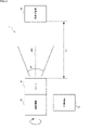
- FIG. 1 is a block diagram showing an embodiment of a measurement system 1 to which this technology is applied.
- the measurement system 1 includes a camera 11, an external terminal 12, a rotation mechanism 13, and an object 14 to be measured.
- the measurement system 1 is a system that detects the center of stabilization of the camera 11 and sets the principal point (Cx, Cy) of the internal parameters of the camera 11 based on the detection result of the center of stabilization.
- the principal point of the camera 11 is not the principal point of the optical center of the camera 11, but the principal point (Cx, Cy) of the internal parameters of the camera 11. do.
- the camera 11 is attached to the rotation mechanism 13 and photographs the object 14 to be measured.
- the external terminal 12 is composed of, for example, a general-purpose terminal such as a smartphone, tablet, or PC (Personal Computer), or a dedicated terminal for camera calibration.
- the external terminal 12 performs wireless or wired communication with the camera 11 .
- the rotation mechanism 13 is a mechanism that rotates the camera 11 in the roll direction around the rotation axis AR1.
- the roll direction of the camera 11 is the direction in which the lens 103 rotates around the optical axis (the Z axis of the camera coordinate system).
- the measurement object 14 is an object that provides feature points used for detecting the center of stabilization of the camera 11 .
- the camera 11 and the measurement object 14 face the camera 11, and are installed so that the feature points of the measurement object 14 do not protrude from the viewing angle ⁇ 1 of the camera 11 when the camera 11 rotates around the rotation axis AR1. be.
- L the distance between the camera 11 and the object 14 to be measured.
- FIG. 2 schematically shows an example of the hardware configuration of the camera 11. As shown in FIG.
- the camera 11 includes a housing 101, a support substrate 102, a lens 103, an image sensor 104, a motion sensor 105, a DSP (Digital Signal Processor) 106, and a stabilization chip 107.
- a DSP Digital Signal Processor
- the support substrate 102 is installed in the housing 101 so as to be substantially perpendicular to the optical axis AC1 of the lens 103.
- the lens 103 is installed at a predetermined position on the housing 101 and forms an image of the subject on the light receiving surface of the image sensor 104 .
- the image sensor 104 is installed on the support substrate 102 so as to be substantially perpendicular to the optical axis AC1 of the lens 103.
- the image sensor 104 captures the image of the subject formed by the lens 103 and generates a captured image.
- the motion sensor 105 is installed on the surface of the support substrate 102 opposite to the surface on which the image sensor 104 is installed.
- the motion sensor 105 includes, for example, a gyro sensor and an acceleration sensor, and detects angular velocity and acceleration of the camera 11 .
- the DSP 106 is installed on the inner surface of the housing 101.
- the DSP 106 executes various image processing and the like on the captured image.
- the stabilization chip 107 is installed on the inner surface of the housing 101 .
- a stabilization chip 107 performs stabilization processing on a captured image.
- FIG. 3 shows an example configuration of the functions of the camera 11 and the external terminal 12 in FIG.
- the camera 11 includes a parameter setting unit 121, a mesh setting unit 122, an offset setting unit 123, a stabilization processing unit 124, and a UI (User Interface) processing unit 125. , a signal processing unit 126 , an image clipping unit 127 , and an I/O (Input/Output) interface unit 128 .
- the image sensor 104, the parameter setting unit 121, the mesh setting unit 122, the offset setting unit 123, the stabilization processing unit 124, the UI processing unit 125, the signal processing unit 126, the image clipping unit 127, and the I/O interface unit 128 are connected to the bus. are connected to each other through
- the image sensor 104 supplies captured image data corresponding to the captured image to the stabilization processing unit 124 and the signal processing unit 126 .
- the parameter setting unit 121 inputs input information including the internal parameters of the camera 11 input from the external terminal 12, and principal point information indicating the detection result of the principal point of the camera 11 by the detection unit 155 of the external terminal 12, to I/ It receives from the external terminal 12 via the O interface unit 128 .
- a parameter setting unit 121 sets internal parameters of the camera 11 based on the input information and the principal point information.
- the parameter setting unit 121 supplies parameter information regarding the set internal parameters to the stabilization processing unit 124 . Also, the parameter setting section 121 transmits the parameter information to the external terminal 12 via the I/O interface section 128 .
- the mesh setting unit 122 receives from the external terminal 12 via the I/O interface unit 128 the mesh information regarding the mesh of the camera coordinate system generated by the mesh generating unit 153 of the external terminal 12 .
- the mesh setting unit 122 sets the mesh of the camera coordinate system by storing the mesh information. Also, the mesh setting unit 122 supplies the mesh information to the image clipping unit 127 .
- the offset setting section 123 receives offset information indicating the offset value of the motion sensor 105 adjusted by the offset adjustment section 154 of the external terminal 12 from the external terminal 12 via the I/O interface section 128 .
- the offset setting unit 123 sets the offset value of the motion sensor 105 based on the offset information.
- the offset setting unit 123 generates motion sensor information indicating the angular velocity and acceleration of the camera 11 measured by the motion sensor 105 and supplies it to the stabilization processing unit 124 . Also, the offset setting section 123 transmits the motion sensor information to the external terminal 12 via the I/O interface section 128 .
- the stabilization processing unit 124 is implemented by, for example, the stabilization chip 107 in FIG.
- the stabilization processing unit 124 performs stabilization processing on the captured image based on the parameter information and the motion sensor information.
- the stabilization process is a process (homography process) of projectively transforming the captured image in accordance with the rotation of the camera 11 .
- the stabilization processing unit 124 supplies the captured image data corresponding to the captured image after stabilization processing to the signal processing unit 126 .
- the UI processing unit 125 executes processing related to the user interface of the camera 11.
- the signal processing unit 126 is realized by the DSP 106 in FIG. 2, for example.
- the signal processing unit 126 performs various kinds of signal processing on the captured image before or after stabilization processing.
- the signal processing unit 126 transmits captured image data corresponding to the captured image before stabilization processing to the external terminal 12 via the I/O interface unit 128 .
- the signal processing unit 126 supplies the captured image data corresponding to the captured image after the stabilization process to the image clipping unit 127 .
- the image clipping unit 127 clips an image of a predetermined size from the captured image after stabilization processing based on the mesh information.
- the image clipping unit 127 transmits clipped image data corresponding to the clipped photographed image (hereinafter referred to as a clipped image) to the external terminal 12 via the I/O interface unit 128 .
- the I/O interface unit 128 is wired or wirelessly connected to the external terminal 12 and communicates with the external terminal 12 .
- the I/O interface unit 128 When the I/O interface unit 128 is connected to the external terminal 12 by wire, it includes, for example, a generally used external connection connector.
- the external terminal 12 includes an I/O interface section 151, a UI processing section 152, a mesh creation section 153, an offset adjustment section 154, a detection section 155, and a display operation section 156.
- the I/O interface unit 151, UI processing unit 152, mesh creation unit 153, offset adjustment unit 154, detection unit 155, and display operation unit 156 are interconnected via a bus.
- the I/O interface unit 151 is wired or wirelessly connected to the camera 11 and communicates with the camera 11 .
- the I/O interface unit 151 When the I/O interface unit 151 is wired-connected to the camera 11, it includes, for example, a generally used external connection connector.
- the UI processing unit 152 executes processing related to the user interface of the external terminal 12. For example, the UI processing unit 152 performs display control of the display operation unit 156 .
- the mesh creation unit 153 receives parameter information from the camera 11 via the I/O interface unit 151 .
- the mesh creation unit 153 creates a mesh of the camera coordinate system so as to have a desired format for the camera 11 based on the parameter information.
- the mesh creation unit 153 generates mesh information regarding the created mesh and transmits it to the camera 11 via the I/O interface unit 151 .
- the offset adjustment unit 154 receives motion sensor information from the camera 11 via the I/O interface unit 151 .
- the offset adjuster 154 adjusts the offset value of the motion sensor 105 based on the motion sensor information.
- the offset adjustment unit 154 generates offset information indicating the offset value of the motion sensor 105 after adjustment, and transmits it to the camera 11 via the I/O interface unit 151 .
- the detection unit 155 receives captured image data and clipped image data from the camera 11 via the I/O interface unit 151 .
- the detection unit 155 detects feature points in the captured image data and the clipped image data, and supplies information about the detected feature points to the UI processing unit 152 .
- the detection unit 155 detects the center of stabilization based on the captured image data and the clipped image data, and detects the principal point of the camera 11 based on the detection result of the center of stabilization.
- the detection unit 155 generates principal point information indicating the detection result of the principal point of the camera 11 and transmits it to the camera 11 via the I/O interface unit 151 .
- the display operation unit 156 is configured by, for example, a touch panel, or a combination of a display device such as a monitor and a keyboard, and an operation member.
- the display operation unit 156 is used, for example, to display various types of information and to input operation signals and various types of information to the camera 11 and the external terminal 12 .
- the display operation unit 156 displays captured images, clipped images, feature points and optical flows of the captured images and clipped images, measurement results of the motion sensor 105, and the like.
- the display operation unit 156 displays a setting screen under the control of the UI processing unit 152, and enables setting, creation, confirmation, etc. of various types of information.
- Information that can be set, created, confirmed, etc. on the setting screen includes, for example, internal parameters of the camera 11, mesh information of the camera coordinate system, setting information related to feature point detection, setting information related to stabilization processing, and settings related to stabilization-centered detection processing. information, setting information on signal processing, and setting information on shooting (for example, aperture, shutter speed, gain, AE (automatic exposure), etc.).
- Information that can be set, created, confirmed, etc. on the setting screen includes, for example, information on each part of the camera 11 and the external terminal 12 .
- the display operation unit 156 supplies input information regarding input operation signals and various types of information to each unit of the external terminal 12 . Also, the display operation unit 156 transmits input information to the camera 11 via the I/O interface unit 151 .
- the configuration of the camera 11 and the external terminal 12 in FIG. 3 is an example, and can be changed as appropriate. For example, it is possible to change the division of functions between the camera 11 and the external terminal 12 .
- the mesh creation unit 153 and the offset adjustment unit 154 can be provided in the camera 11 instead of the external terminal 12.
- the mesh creation unit 153, the offset adjustment unit 154, and the detection unit 155 can be provided in the camera 11 instead of the external terminal 12.
- the mesh setting unit 122 and the mesh creation unit 153 can be integrated into one.
- the offset setting section 123 and the offset adjustment section 154 can be combined into one.
- the camera 11 may be provided with an operation unit and a display unit.
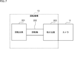
- FIG. 7 shows a first embodiment of the rotating mechanism 13. As shown in FIG.
- the rotating mechanism 13 includes a rotating jig 201 , a rotating shaft 202 and a mounting jig 203 .
- the rotating jig 201 and the mounting jig 203 are connected via a rotating shaft 202 .
- the rotating jig 201 is a jig for rotating the rotating shaft 202 .
- the rotating jig 201 is configured by a handle or the like, which will be described later.
- the attachment jig 203 is a jig for attaching the camera 11 to the rotation mechanism 13 .
- the mounting jig 203 connected to the rotating shaft 202 and the camera 11 attached to the mounting jig 203 rotate.
- FIG. 8 shows a second embodiment of the rotating mechanism 13. As shown in FIG. In the figure, the parts corresponding to those of the rotating mechanism 13 in FIG. 7 are denoted by the same reference numerals, and description thereof will be omitted as appropriate.
- the rotation mechanism 13 of FIG. 8 has a configuration in which an angle jig 204 is added to the rotation mechanism 13 of FIG.
- the angle jig 204 is provided between the rotating jig 201 and the mounting jig 203 .
- the angle jig 204 is a jig capable of changing the angles of the mounting jig 203 in the pitch direction and the yaw direction. By adjusting the angles of the angle jig 204 in the pitch and yaw directions, it is possible to adjust the angles of the camera 11 attached to the mounting jig 203 in the pitch and yaw directions.
- FIG. 9 and 10 show a third embodiment of the rotating mechanism 13.
- FIG. 9 is a plan view of the rotation mechanism 13
- FIG. 10 is a block diagram showing a configuration example of the rotation mechanism 13. As shown in FIG. In the figure, parts corresponding to those of the rotating mechanism 13 in FIG. 8 are denoted by the same reference numerals, and description thereof will be omitted as appropriate.
- the rotating mechanism 13 includes a rotating shaft 202, a mounting jig 203, a mounting base 221, a handle 222, bearings 223-1, and bearings 223-2.
- the rotary shaft 202 is fixed by bearings 223-1 and 223-2 installed on the installation table 221 and is rotatable.
- a handle 222 is attached to one end of the rotating shaft 202
- a mounting jig 203 is attached to the other end of the rotating shaft 202 .
- a camera 11 is attached to an attachment jig 203 .
- the user can rotate the camera 11 in the roll direction around the rotation axis 202 by rotating the handle 222 .
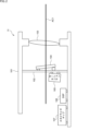
- FIG. 11 and 12 show a fourth embodiment of the rotating mechanism 13.
- FIG. 11 is a plan view of the rotation mechanism 13
- FIG. 12 is a block diagram showing a configuration example of the rotation mechanism 13. As shown in FIG. 9 and 10 are denoted by the same reference numerals, and description thereof will be omitted as appropriate.
- the rotating mechanism 13 includes a mounting jig 203, a handle 222, bearings 223-1 to 223-4, a mounting table 241, a rotating shaft 242, gears 243-1 and 243-2, a timing belt 244, a rotating shaft 245, and a cable. 246 and an I/O interface unit 247 .
- the rotary shaft 242 is fixed by bearings 223-1 and 223-2 installed on the installation table 221 and is rotatable.
- a handle 222 is installed at one end of the rotating shaft 242 .
- a gear 243 - 1 is installed near the center of the rotating shaft 242 .
- the rotating shaft 245 is fixed parallel to the rotating shaft 242 by bearings 223-3 and 223-4 installed on the installation table 221, and is rotatable.
- a mounting jig 203 is installed at one end of the rotating shaft 245 .
- a gear 243 - 2 is installed on the rotating shaft 245 at a position corresponding to the gear 243 - 1 on the rotating shaft 242 .
- a timing belt 244 connects the gears 243-1 and 243-2. Therefore, by rotating the handle 222, the rotating shaft 242 rotates, and the rotation of the rotating shaft 242 is transmitted to the rotating shaft 245 by the gear 243-1, the timing belt 244, and the gear 243-2. As a result, the rotating shaft 245 rotates, and the camera 11 attached to the mounting jig 203 rotates about the rotating shaft 245 in the roll direction.
- a cable 246 passes through the inside of the rotating shaft 245 and connects the camera 11 and the I/O interface section 247 .
- the I/O interface unit 247 is, for example, wired or wirelessly connected to the external terminal 12 shown in FIGS. 3 to 5, and communicates with the external terminal 12.
- the I/O interface unit 247 When the I/O interface unit 247 is connected to the external terminal 12 by wire, it includes, for example, a generally used external connection connector.
- a motor may be provided instead of the handle 222 to mechanically rotate the rotating shaft 202 or the rotating shafts 242 and 245 .
- a stepping motor can be used as the motor.
- the user can manually rotate the camera 11 in the roll direction or manually rotate the camera 11 in the roll direction to a predetermined rotation position (roll position), as will be described later. direction angle).
- FIG. 13 the relationship between the shift between the center of the lens 103 of the camera 11 and the rotation axis AR1 of the rotation mechanism 13 and the stabilization process will be described with reference to FIGS. 13 to 20.
- FIG. 13 the relationship between the shift between the center of the lens 103 of the camera 11 and the rotation axis AR1 of the rotation mechanism 13 and the stabilization process will be described with reference to FIGS. 13 to 20.
- FIG. 13 shows an example in which the center CL1 of the lens 103 of the camera 11 and the rotation axis AR1 of the rotation mechanism 13 overlap.
- the rotation axis AR1 passes through the center CL1 of the lens 103 and substantially overlaps with the optical axis AO1 of the lens 103 .
- FIG. 14 shows an example of the trajectory of feature points in a photographed image of the measurement object 14 when the center CL1 of the lens 103 and the rotation axis AR1 overlap.
- the center of the camera coordinate system and the center of the image coordinate system (captured image) substantially overlap with the rotation axis AR1.
- the measurement object 14 has a pattern indicating 3 rows ⁇ 3 columns of dots (feature points).
- FIG. 14B shows an example of the trajectory of the feature points in the captured image when the camera 11 is rotated in the roll direction around the rotation axis AR1 without executing the stabilization process.
- the feature points move circularly around the center of the captured image.
- FIG. 14C shows an example of the trajectory of the feature points in the captured image when the camera 11 is rotated in the roll direction around the rotation axis AR1 while the stabilization process is being performed. In this example, even if the camera 11 rotates, the feature points remain stationary and do not move.
- the stabilization center can be accurately detected in the stabilization center detection process described later.
- FIG. 15 shows an example in which the center CL1 of the lens 103 of the camera 11 and the rotation axis AR1 of the rotation mechanism 13 are shifted by a distance t. In this case, a deviation of the length t also occurs between the rotation axis AR1 and the optical axis AO1 of the lens 103 .
- FIG. 16 shows an example of the trajectory of feature points in a photographed image of the measurement object 14 when the center CL1 of the lens 103 and the rotation axis AR1 are displaced by a distance t. .
- the center of the camera coordinate system and the center of the image coordinate system (captured image) are shifted from the rotation axis AR1 by a distance t.
- FIG. 16B shows an example of the trajectory of the feature points in the captured image when the camera 11 is rotated in the roll direction around the rotation axis AR1 without executing the stabilization process.
- the center of the image coordinate system rotates as the camera 11 rotates. Therefore, in the photographed image, the feature point is moved by the sum of the rotational component associated with the rotation of the camera 11 and the rotational component of the center of the image coordinate system.
- FIG. 16C shows an example of the trajectory of the feature points in the captured image when the camera 11 is rotated in the roll direction around the rotation axis AR1 while performing the stabilization process.
- the feature points move circularly according to the rotation of the center of the image coordinate system.
- the stabilization center cannot be accurately detected in the stabilization center detection process described later.
- the mounting jig 203 it is desirable to adjust at least one of the position of the camera 11 and the position of the mounting jig 203 so that the center CL1 of the lens 103 and the rotation axis AR1 overlap.
- an XY stage 251 may be used as the mounting jig 203 as shown in FIG.
- the XY stage 251 is a member capable of horizontally and vertically moving the stage on which the camera 11 is installed. As a result, for example, as shown in FIG. 17A, even if there is a misalignment between the center CL1 of the lens 103 and the rotation axis AR1, by moving the XY stage 251, the position shown in FIG. The center CL1 of the lens 103 can be superimposed on the rotation axis AR1 so that
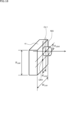
- the amount of deviation between the center of the camera coordinate system and the center of the image coordinate system and the rotation axis AR1 may be corrected.
- the center of rotation when the camera 11 is rotated by rotating the rotation mechanism 13 is defined as CR1.
- the rotation center CR ⁇ b>1 overlaps the rotation axis AR ⁇ b>1 of the rotation mechanism 13 .
- the height (vertical distance) between the center of rotation CR1 and the center CL1 of the lens 103 is defined as H_LENS
- the width (distance in the horizontal direction) is defined as W_LENS .
- the height of the camera 11 is designated as H CAM
- the width as W CAM .
- the amount of deviation between the center of the camera coordinate system of the camera 11 and the rotation axis AR1 is assumed to be t.
- the amount of deviation t the amount of deviation in the height (vertical) direction is defined as th
- the amount of deviation in the lateral (horizontal) direction is defined as tw .
- PC1 the point at which the object 14 to be measured and the rotation axis AR1 intersect
- the amount of deviation between the center of the image coordinate system and the rotation axis AR1 is assumed to be tf .
- the amount of deviation tf the amount of deviation in the height (vertical) direction is tfh
- the amount of deviation in the lateral (horizontal) direction is tfw .
- FIG. 20A shows the relationship between the amount of deviation t in the camera coordinate system and the distance L between the camera 11 and the object 14 to be measured.
- B of FIG. 20 shows the relationship between the shift amount tf in the image coordinate system and the focal length f of the lens 103 .
- the triangle of A in FIG. 20 and the triangle of B in FIG. 20 are similar. Further, the deviation amount tv and the deviation amount th in the camera coordinate system are represented by the following equations (1) and (2).
- the deviation amount tfv and the deviation amount tfh in the image coordinate system are represented by the following equations (3) and (4).
- the displacement amount t fv and the displacement amount t fh are obtained by the following equation (5 ) and (6), 0.5 pixels.
- the detection unit 155 of the external terminal 12 acquires information on H LENS , W LENS , the distance L, and the focal length f from the outside, and calculates the deviation amount t fv and the deviation amount t fh of the image coordinate system. Then, after detecting the center of stabilization in a process described later, the detection unit 155 corrects the detected value by the deviation amount tfv and the deviation amount tfh . As a result, an error in the center of stabilization caused by the amount of deviation between the center of the camera coordinate system of the camera 11 and the rotation axis AR1 of the rotation mechanism 13 is corrected, and the detection accuracy of the center of stabilization is improved.
- the distance between the camera 11 and the measurement object 14 may be set to infinity.
- the amount of deviation tfv and the amount of deviation tfh become substantially 0, and correction of the detected value at the center of stabilization becomes unnecessary.
- FIGS. 21 and 22 differ from the example of FIG. 13 in that an angle jig 204 is provided between the rotating shaft 202 and the mounting jig 203 .
- the angle jig 204 is a jig for tilting the optical axis AO1 of the lens 103 of the camera 11 with respect to the rotation axis AR1 of the rotation mechanism 13 by an angle ⁇ .
- the camera 11 can be installed so that the orientation of the optical axis AO1 (the Z axis of the camera coordinate system) with respect to the rotation axis AR1 becomes an angle ⁇ .
- the amount of change in the motion sensor 105 (the angular velocity and acceleration of the camera 11) can be increased, improving the detection accuracy of the stabilization center.
- the angle jig 204 may change the orientation of the camera 11 (angle ⁇ ), or may fix the orientation of the camera 11 .
- the angle ⁇ it is desirable to set the angle ⁇ to a value sufficiently smaller than 1/2 ( ⁇ /2) of the viewing angle ⁇ of the lens 103 . If the angle ⁇ is set to ⁇ /2 or more, the measurement object 14 protrudes from the image coordinate system when the camera 11 rotates, making it impossible to detect the feature points of the measurement object 14 and the stabilization center. Because there is
- the position of the camera 11 can be adjusted so that the center CL1 of the lens 103 overlaps the rotation axis AR1. good.
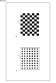
- FIG. 24 shows an example in which a board, which is a plate-shaped member showing a pattern containing a single feature point, is used as the measurement object 14.
- FIG. 24 shows an example in which a board, which is a plate-shaped member showing a pattern containing a single feature point, is used as the measurement object 14.
- FIG. 24A shows an example in which a board with a circular mark arranged in the center is used as the measurement object 14.
- FIG. 24B shows an example of using a board showing a set of grids as the measurement object 14.
- FIG. 25 shows an example in which a board, which is a plate-shaped member showing a pattern including a plurality of characteristic points, is used as the measurement object 14.
- FIG. 25 shows an example in which a board, which is a plate-shaped member showing a pattern including a plurality of characteristic points, is used as the measurement object 14.
- FIG. 25A shows an example in which a board on which a plurality of circular marks are arranged in a grid pattern is used as the measurement object 14.
- FIG. 25A shows an example in which a board on which a plurality of circular marks are arranged in a grid pattern is used as the measurement object 14.
- FIG. 25B shows an example in which a board showing a grid pattern is used as the measurement object 14.
- the measurement object 14 When a board showing a predetermined pattern is used as the measurement object 14, it is assumed that the measurement object 14 is installed indoors. Therefore, it is desirable to set the distance L between the camera 11 and the measurement object 14 to several centimeters to several tens of meters.
- grid patterns such as B in FIG. 24 and B in FIG. 25 may be deformed when viewed obliquely, and the detection accuracy of feature points may decrease. Therefore, it is preferable to use a board on which circular marks are arranged as shown in FIGS. 24A and 25A.
- FIG. 26 shows an example of using an external object as the measurement object 14.
- FIG. 26A shows an example of using an outdoor house or building as the measurement object 14.
- FIG. 26A shows an example of using an outdoor house or building as the measurement object 14.
- FIG. 26B shows an example of using outdoor signs and utility poles as measurement objects 14 .
- the external object used as the measurement object 14 can be an object whose feature points can be detected and whose feature points are stationary, other than the example in FIG.
- fixed objects such as trees, bridges, mountains, and rivers, stationary stars such as the North Star, and the like can be used as the measurement object 14 .
- the distance L between the camera 11 and the measurement target 14 is desirable to set the distance L between the camera 11 and the measurement target 14 to several tens of meters or more, or a distance equivalent to infinity.
- an environment for detecting the stabilization center is constructed as shown in FIG. 1 described above. That is, the camera 11 is attached to the rotation mechanism 13 and the measurement object 14 is installed so as to face the camera 11 .
- the size of the image sensor 104 is 4000 pixels long by 4000 pixels wide, and the lens 103 is a fisheye lens with a viewing angle of 180° and a focal length of 1000 pixels per pixel will be described below. Further, it is assumed that the camera 11 and the rotation mechanism 13 are installed so that the center CL1 of the lens 103 and the rotation axis AR1 of the rotation mechanism 13 overlap.
- step S1 the measurement system 1 captures and displays the measurement object 14.
- the image sensor 104 of the camera 11 captures an image of the measurement object 14 through the lens 103 and supplies the obtained captured image data to the signal processing unit 126 .
- the signal processing unit 126 performs various signal processing on the captured image, and transmits the captured image data after the signal processing to the external terminal 12 via the I/O interface unit 128 .
- the I/O interface unit 151 of the external terminal 12 receives the captured image data from the external terminal 12.
- the I/O interface unit 151 supplies captured image data to each unit of the external terminal 12 .
- the display operation unit 156 displays a photographed image showing the measurement object 14 based on the photographed image data. As a result, for example, as shown in FIG. 28, a photographed image of the object 14 to be measured is displayed on the display/manipulation unit 156 .
- step S2 the external terminal 12 acquires the internal parameters of the camera 11.
- the user inputs internal parameters of the camera 11 via the display operation unit 156 of the external terminal 12 .
- the intrinsic parameters of the camera 11 include the camera 11 principal point (Cx, Cy), focal length (fx, fy), and correction coefficients k 1 to k 4 , p 1 and p 2 . These internal parameters are used for distortion correction and stabilization processing of the lens 103 .
- distortion correction of the lens 103 is performed using the following equations (7) to (12).
- the coordinates (Xc, Yc, Zc) are the coordinates of the camera coordinate system of the camera 11, and the coordinates (u, v) are the coordinates of the captured image in the image coordinate system.
- distortion correction of the lens 103 is performed using, for example, the following equations (13) to (20).
- the focal length (fx, fy) and the correction coefficients k 1 to k 4 , p 1 and p 2 use the lens manufacturer's specification values or guaranteed values.
- parameters measured using a lens parameter measuring instrument are used.
- the coordinates of the center of the captured image are tentatively set.
- the display operation unit 156 generates input information including the input internal parameters and supplies it to each unit of the external terminal 12 . Also, the display operation unit 156 transmits input information to the camera 11 via the I/O interface unit 151 .
- the parameter setting section 121 of the camera 11 receives input information via the I/O interface section 128 .
- the parameter setting unit 121 sets internal parameters of the camera 11 based on the input information.
- the parameter setting unit 121 generates parameter information regarding the set internal parameters, and supplies the parameter information to the stabilization processing unit 124 .
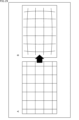
- step S3 the measurement system 1 creates and sets the mesh of the camera coordinate system.
- the mesh creation unit 153 of the external terminal 12 creates a mesh of the camera coordinate system based on the internal parameters of the camera 11 acquired in step S2.
- a camera coordinate system mesh that reflects the distortion of the lens 103 as shown in FIG. 29B is created for a normal camera coordinate system mesh. be done.
- Any method can be applied to create the mesh of the camera coordinate system.
- the methods described in Patent Document 1, Japanese Patent Application Laid-Open No. 2013-134088, or International Publication No. 2020-039747 can be applied.
- a plurality of types of mesh may be prepared in advance, and an appropriate mesh may be selected from among them based on the internal parameters of the camera 11.
- the mesh creation unit 153 generates mesh information regarding the created mesh and transmits it to the camera 11 via the I/O interface unit 151.
- the mesh setting unit 122 of the camera 11 receives mesh information from the external terminal 12 via the I/O interface unit 128.
- the mesh setting unit 122 sets the mesh of the camera coordinate system based on the mesh information.
- the mesh setting unit 122 generates mesh information regarding the set mesh and supplies it to the image clipping unit 127 .
- step S4 the display operation unit 156 of the external terminal 12 displays the center of the captured image under the control of the UI processing unit 152.
- a cross mark which is information indicating the position of the center of the captured image, is superimposed on the captured image displayed on the display operation unit 156 .
- the user can adjust the center of the captured image so that the center of the measurement object
- the position of the measuring object 14 is adjusted so that it overlaps with the center of the object 14 .
- step S5 the external terminal 12 detects and displays feature points of the captured image.
- the detection unit 155 of the external terminal 12 detects feature points of the captured image.
- Any method can be applied to detect feature points.
- Moravec's corner detection algorithm Harris, Stephens, and Plessey's corner detection algorithm
- multiscale Harris operator Shi and Tomasi's method
- curvature-based method Laplacian-Gaussian and derivative methods
- Wang and Brady's method Trajkovic and Techniques such as Hedley's technique and FAST feature detection can be applied.
- the detection unit 155 supplies information on the detected feature points to the UI processing unit 152 .
- the display operation unit 156 superimposes information indicating the position of the feature point on the captured image being displayed.
- the center of the measurement object 14 in the captured image is detected as the feature point PF1, and information indicating the position of the detected feature point PF1 is displayed on the display operation unit 156. It is superimposed on the captured image inside.
- the user uses the display operation unit 156 to select one feature point to be used for detecting the center of stabilization, and to prevent other feature points from being displayed.
- the user can use the display operation unit 156 to change the feature point detection method and detection parameters. good too.
- the user uses the rotation mechanism 13 to rotate the camera 11 in the roll direction.
- the display operation unit 156 superimposes the trajectory of the feature point PF1 on the captured image under the control of the UI processing unit 152. Then, the user confirms that the feature point PF1 does not disappear and is continuously displayed on the display operation unit 156 even when the camera 11 is rotated. That is, the user confirms that the feature point PF1 does not protrude from the viewing angle ⁇ 1 of the camera 11 even if the camera 11 is rotated.
- the user adjusts the position of the measurement object 14 so that the feature point PF1 does not protrude from the viewing angle ⁇ 1 of the camera 11.
- the user may, if necessary, adjust the position of the measurement object 14 so that the center of the circle indicating the trajectory of the feature point PF1 substantially overlaps with the center of the captured image, as shown in FIG. 32B. to adjust.
- step S6 the camera 11 starts stabilization processing.
- the user uses the operation unit (not shown) of the camera 11 to turn on the camera shake correction function.
- the UI processing unit 125 sets the camera shake correction function to ON and notifies each unit of the camera 11 that the camera shake correction function has been set to ON.
- the stabilization processing unit 124 executes stabilization processing. For example, the stabilization processing unit 124 converts the coordinates (u, v) of the captured image to the coordinates (u′, v ') to perform the stabilization process.
- the rotation matrix R and the projective transformation matrix K are represented by the following equations (22) to (24).
- ⁇ pitch , ⁇ yaw , and ⁇ roll represent the rotation angle in the pitch direction, the rotation angle in the yaw direction, and the rotation angle in the roll direction, respectively.
- rotation vector for example, quaternion, rotation matrix SO(3), Euler angles, etc.
- quaternion rotation matrix SO(3), Euler angles, etc.
- the stabilization processing unit 124 supplies the captured image data after stabilization processing to the image clipping unit 127 .
- the image clipping unit 127 clips an image of a predetermined size from the captured image based on the mesh information supplied from the mesh setting unit 122. For example, the image clipping unit 127 clips a clipped image of 1920 pixels high by 1080 pixels wide from a captured image of 4000 pixels high x 4000 pixels wide. For example, if the viewing angle of the captured image is 180°, the viewing angle of the clipped image can be set to 90°. Note that the viewing angle of the clipped image can be set to an angle other than 90°.
- the image clipping unit 127 transmits clipped image data corresponding to the clipped image clipped from the captured image to the external terminal 12 via the I/O interface unit 128 .
- the I/O interface section 128 of the external terminal 12 receives the cropped image data and supplies it to each section of the external terminal 12 .
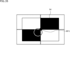
- the detection unit 155 detects feature points of the clipped image based on the clipped image data, and supplies information about the detected feature points to the UI processing unit 152 .
- the display operation unit 156 displays the clipped image based on the clipped image data under the control of the UI processing unit 152 .
- the display operation unit 156 superimposes information indicating the positions of the cross mark and the feature point on the clipped image.
- a clipped image including the measurement object 14 and superimposed with information indicating the position of the cross mark and the feature point PF1 is displayed on the display operation unit 156.
- step S7 the external terminal 12 starts tracking feature points.
- the user uses the display operation unit 156 to perform an operation to turn on the optical flow function.
- the UI processing unit 152 turns on the optical flow function and notifies each unit of the external terminal 12 that the optical flow function has been turned on.
- the detection unit 155 starts tracking the feature points in the clipped image, and supplies the UI processing unit 152 with information on the tracking result of the feature points.
- the user uses the rotation mechanism 13 to rotate the camera 11 in the roll direction.
- the display operation unit 156 superimposes information indicating the trajectory of the feature point PF1 on the clipped image under the control of the UI processing unit 152. Then, the user confirms that the feature point PF1 does not disappear and is continuously displayed on the display operation unit 156 even when the camera 11 is rotated. That is, the user confirms that the feature point PF1 does not protrude from the cropped image even if the camera 11 is rotated.
- the user adjusts the position of the measurement object 14 so that the center of the trajectory of the feature point PF1 substantially overlaps the center of the clipped image, for example, as shown in FIG. 36B.
- step S8 the offset setting unit 123 of the camera 11 determines whether or not the offset of the motion sensor 105 has been corrected. If it is determined that the offset of the motion sensor 105 has not been corrected, the process proceeds to step S9.
- step S9 the measurement system 1 corrects the offset of the motion sensor 105.
- the motion sensor 105 measures the angular velocity of the motion sensor 105 during periods of rest, ie, the zero point of the angular velocity of the motion sensor 105 .
- the angular velocities of the motion sensor 105 are represented, for example, by angular velocities Gx, Gy, and Gz on the X-axis, Y-axis, and Z-axis of the camera coordinate system.
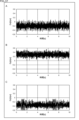
- FIG. 37 shows an example of angular velocity measurements of the motion sensor 105 during a period of rest.
- FIG. 37A shows an example of measured values of the angular velocity Gx.
- B of FIG. 37 shows an example of the output value of the angular velocity Gy.
- C of FIG. 37 shows an example of the measured value of the angular velocity Gz.
- the zero point of the angular velocity Gx is -0.1987 dps.
- the zero point of angular velocity Gy is 0.292656 dps.
- the zero point of the angular velocity Gz is ⁇ 0.34035 dps.
- the offset setting unit 123 generates motion sensor information including the measurement result of the angular velocity of the motion sensor 105 during the stationary period, and transmits it to the external terminal 12 via the I/O interface unit 128 .
- the offset adjustment unit 154 of the external terminal 12 receives the motion sensor information from the camera 11 via the I/O interface unit 151.
- the offset adjustment unit 154 calculates the average of the measured values of the angular velocity Gx, the angular velocity Gy, and the angular velocity Gz during the stationary period as the zero point of the angular velocity Gx, the angular velocity Gy, and the angular velocity Gz.
- the offset adjustment unit 154 calculates offset values for correcting the zero point values of the angular velocities Gx, Gy, and Gz of the motion sensor 105 to zero.
- the offset adjustment unit 154 transmits offset information indicating the calculated offset value to the camera 11 via the I/O interface unit 151 .
- the offset setting section 123 of the camera 11 receives offset information from the external terminal 12 via the I/O interface section 128 .
- the offset setting unit 123 sets the offset value of the angular velocity of the motion sensor 105 based on the offset information.
- the offset values of the acceleration of the motion sensor 105 in the X, Y, and Z axes of the camera coordinate system are also set in the same manner as the angular velocity offset values.
- step S8 determines that the offset of the motion sensor 105 has been corrected. If it is determined in step S8 that the offset of the motion sensor 105 has been corrected, the process of step S9 is skipped and the process proceeds to step S10.
- step S10 the measurement system 1 executes stabilization center detection processing.
- the detection unit 155 sets the position of the feature point PF1 in the image coordinate system of the cropped image after the camera 11 is stationary for a predetermined time (for example, 10 seconds) to the initial value of the stabilization center.
- the user uses the rotation mechanism 13 to rotate the camera 11 in the roll direction a predetermined number of times (for example, 5 times).
- the detection unit 155 detects the position of the feature point PF1 in the image coordinate system of the clipped image of each frame obtained by photographing the camera 11 in a plurality of postures with different angles in the roll direction. To detect.
- the detection unit 155 detects the center and radius of the trajectory of the feature point PF1 for each rotation as variations in the center of stabilization and the position of the feature point PF1, respectively.
- the detection unit 155 uses Hough transform to detect a circle that is the trajectory of the feature point PF1, and detects the center and radius of the detected circle.
- the following shows an example of the detection result of the initial value of the stabilization center and the variations in the positions of the stabilization center and the feature point PF1 in the first to fifth rotations.
- the detection unit 155 for example, by the method described above with reference to FIGS.
- the detection result of the center of stabilization may be corrected.
- the detection unit 155 calculates the average of the center of stabilization and the average of variations in the positions of the feature points PF1.
- the average of the center of stabilization and the average of variations in the positions of the feature points PF1 are as follows.
- the detection unit 155 for example, by the method described above with reference to FIGS.
- the average of the center of stabilization may be corrected.
- the detection unit 155 calculates the difference between the initial value of the center of stabilization and the average of the center of stabilization as the deviation amount of the center of stabilization.
- the amount of deviation of the center of stabilization is as follows.
- the detection unit 155 for example, by the method described above with reference to FIGS.
- the deviation amount of the center of stabilization may be corrected.
- the detection unit 155 calculates the principal point of the camera 11 by subtracting the amount of deviation of the stabilization center from the currently set principal point of the camera 11 .
- the principal point of the camera 11 is provisionally set to (2000, 2000) in step S2. Therefore, the principal point of camera 11 is calculated as follows.
- the coordinates of the principal point of the camera 11 in this formula are the coordinates obtained by transforming the stabilization center in the image coordinate system of the clipped image into the stabilization center in the image coordinate system of the captured image.
- step S11 the detection unit 155 determines whether or not to end the stabilization center detection process. If it is determined to continue the stabilization center detection process, the process proceeds to step S12.
- step S12 the measurement system 1 updates the principal point of the camera 11 used for stabilization processing.
- the detection unit 155 supplies the mesh generation unit 153 with the principal point information indicating the principal point of the camera 11 calculated in the process of step S10, and transmits the information to the camera 11 via the I/O interface unit 151. do.
- the parameter setting section 121 of the camera 11 receives the principal point information from the external terminal 12 via the I/O interface section 128 .
- the parameter setting unit 121 updates the currently set principal point of the camera 11 to the value indicated by the principal point information.
- the parameter setting unit 121 supplies the stabilization processing unit 124 with parameter information regarding internal parameters including the updated principal point of the camera 11 .
- step S3 the process returns to step S3, and the processes from step S3 to step S12 are repeatedly executed until it is determined in step S11 that the stabilization center detection process is finished.
- the stabilization center detection process is repeatedly executed while the principal point of the camera 11 used for the stabilization process in the next detection process is updated based on the stabilization center detection result.
- step S11 determines to end the stabilization center detection process.
- the detection unit 155 determines to end the stabilization center detection processing when the stabilization center detection processing has been performed a predetermined number of times (for example, five times).
- step S13 the measurement system 1 corrects the principal point of the camera 11.
- the detection unit 155 of the external terminal 12 executes the stabilization center detection process a plurality of times, and in the detection process at which the average variation in the position of the feature point PF1 is minimized, the camera 11 used for the stabilization process A principal point is determined to be the principal point of the camera 11 .
- the detection results when the detection process is executed five times are as follows, the average variation in the positions of the feature points PF1 in the third detection process is minimized. Therefore, (1933, 1997), which is the principal point of camera 11 used in the third detection process, is determined as the principal point of camera 11 .
- the detection unit 155 supplies principal point information indicating the set principal points of the camera 11 to the mesh creation unit 153 and also transmits the information to the camera 11 via the I/O interface unit 151 .
- the parameter setting section 121 of the camera 11 receives the principal point information from the external terminal 12 via the I/O interface section 128 .
- the parameter setting unit 121 corrects the currently set principal point of the camera 11 to the value indicated by the principal point information.
- the parameter setting unit 121 supplies the stabilization processing unit 124 with parameter information regarding internal parameters including the corrected principal point of the camera 11 .
- step S14 the measurement system 1 corrects the camera coordinate system mesh.
- the mesh creation unit 153 of the external terminal 12 creates a mesh of the camera coordinate system based on the internal parameters including the principal point of the camera 11 corrected in step S13.
- the mesh creation unit 153 generates mesh information regarding the created mesh of the camera coordinate system, and transmits it to the camera 11 via the I/O interface unit 151 .
- the mesh setting unit 122 of the camera 11 receives mesh information from the external terminal 12 via the I/O interface unit 128.
- the mesh setting unit 122 corrects the mesh of the camera coordinate system based on the received information.
- the mesh setting unit 122 supplies mesh information regarding the corrected mesh to the image clipping unit 127 .
- the user checks the operation of the camera shake correction function. Specifically, for example, the user turns on/off the power of the camera 11, sets the camera shake correction function to on, and then rotates the rotation mechanism 13 so that the feature points of the measurement object 14 do not move and remain stationary. Make sure you are
- the center of stabilization can be determined for each individual camera 11 without using a highly flat checkerboard or the like. Simple and easy to detect. Further, the center of stabilization can be detected in a state in which stabilization processing is actually performed using the motion sensor 105 provided in the camera 11 . Furthermore, the principal point of the camera 11 used for stabilization processing can be set based on the detected stabilization center.
- the detection unit 155 can detect the stabilization center by the method described above with reference to FIG. 27 while the user manually rotates the camera 11 in the roll direction without using the rotation mechanism 13 .
- the distance between the camera 11 and the measurement object 14 is set to infinity, and the camera 11 is rotated. You should let it run.
- the trajectory of the feature points of the clipped image when the camera 11 is rotated does not necessarily have to be circular, and may be oval or distorted, for example. Then, as in the case where the trajectory of the feature points is circular, the center of the trajectory of the feature points may be detected as the stabilization center.
- the cropped image, the feature points, the trajectory of the feature points, etc. are displayed on the display operation unit 158 of the external terminal 12 in the same manner as described above. Therefore, the user can manually rotate the camera 11 in the roll direction while checking the captured image, the state of the feature points, and the like, and detect the center of stabilization.
- the camera 11 is rotated in the roll direction with the camera shake correction function set to ON, and the measurement object 14 is photographed with the camera 11 while the camera 11 is installed in a plurality of postures with different angles in the roll direction.
- the stabilization center may be detected based on the positions of the feature points of the clipped image obtained in the posture.
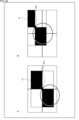
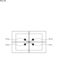
- the user places the camera 11 facing the object 14 to be measured, sets the camera shake correction function to ON, and installs the camera 11 on a table or the like in a normal posture. That is, the camera 11 is placed on a stand or the like with its bottom face down.
- the camera 11 photographs the measurement object 14 in this first posture.
- the detection unit 155 of the external terminal 12 detects the feature point PF1a of the measurement object 14 in the cropped image cut from the captured image captured in the first posture, as shown in FIG. 38A.
- the user places the camera 11 against the object 14 to be measured, rotates the camera 11 counterclockwise by 90 degrees in the roll direction with the camera shake correction function turned on, and places the camera 11 on a table or the like.
- the camera 11 photographs the measurement object 14 in this second posture.
- the detection unit 155 of the external terminal 12 detects the feature point PF1b of the measurement object 14 in the cropped image cut from the captured image captured in the second posture, as shown in FIG. 38B.
- the user places the camera 11 against the object 14 to be measured, rotates the camera 11 counterclockwise by 90 degrees in the roll direction with the camera shake correction function turned on, and places the camera 11 on a table or the like.
- the camera 11 photographs the measurement object 14 in this third posture.
- the detection unit 155 of the external terminal 12 detects the feature point PF1c of the measurement object 14 in the cropped image cut from the captured image captured in the third posture, as shown in FIG. 38C.
- the user places the camera 11 against the object 14 to be measured, rotates the camera 11 counterclockwise by 90 degrees in the roll direction with the camera shake correction function turned on, and places the camera 11 on a table or the like.
- the camera 11 photographs the measurement object 14 in this fourth posture.
- the detection unit 155 of the external terminal 12 detects the feature points PF1d of the measurement object 14 in the cutout image cut out from the captured image captured in the fourth posture, as shown in FIG. 38D.
- the detection unit 155 of the external terminal 12 detects the center of the feature points PF1a to PF1d as the center of stabilization in the image coordinate system of the cropped image. For example, the detection unit 155 detects the intersection of a straight line connecting the feature points PF1a and PF1c and a straight line connecting the feature points PF1b and PF1d as the stabilization center.
- the cropped image, the feature points, the trajectory of the feature points, etc. are displayed on the display operation unit 158 of the external terminal 12 in the same manner as described above. Therefore, the user can manually rotate the camera 11 in the roll direction while confirming the captured image, the state of the feature points, etc., and detect the center of stabilization while setting the camera 11 in a predetermined posture.
- the distance between the camera 11 and the measurement object 14 should be set to infinity, and the camera 11 should be rotated. Just do it.
- the detected value at the center of stabilization may be corrected by the amount of .
- the postures for photographing the measurement object 14 are not necessarily limited to the four postures described above, and three or more arbitrary postures with different angles in the roll direction can be adopted. However, it is desirable that the angles in the roll direction of each posture be spaced as much as possible. Then, the center of the feature point group detected in each of the plurality of clipped images clipped from the plurality of captured images captured in each posture is detected as the stabilization center. For the center of the feature point group, for example, the center of gravity of the feature point group is used.
- the camera 11 may be rotated clockwise in the roll direction.
- the stabilization center detection process may be terminated when the average variation in the position of the feature point PF1 is equal to or less than a predetermined threshold.
- the stabilization center detection process may be repeated until the average variation in the positions of the feature points PF1 is equal to or less than a predetermined threshold.
- the principal point of the camera 11 used in the detection process in which the average variation in the positions of the feature points PF1 is equal to or less than a predetermined threshold may be determined as the principal point of the camera 11.
- the parameter setting unit 121 may set the principal point of the camera 11 based on the detection result of the stabilization center.
- This technology is applicable to various cameras equipped with a motion sensor and an image stabilization function (e.g., digital still cameras, digital video cameras, surveillance cameras, portable cameras, etc.), devices for adjusting the principal points of these cameras, applicable to the system.
- an image stabilization function e.g., digital still cameras, digital video cameras, surveillance cameras, portable cameras, etc.
- the present technology can be applied to components (for example, LSI, etc.) and software that perform image stabilization functions using motion sensors.
- the series of processes described above can be executed by hardware or by software.
- a program that constitutes the software is installed in the computer.
- the computer includes, for example, a computer built into dedicated hardware and a general-purpose personal computer capable of executing various functions by installing various programs.
- FIG. 40 is a block diagram showing an example of the hardware configuration of a computer that executes the series of processes described above by a program.
- CPU Central Processing Unit
- ROM Read Only Memory
- RAM Random Access Memory
- An input/output interface 1005 is further connected to the bus 1004 .
- An input unit 1006 , an output unit 1007 , a storage unit 1008 , a communication unit 1009 and a drive 1010 are connected to the input/output interface 1005 .
- the input unit 1006 consists of input switches, buttons, a microphone, an imaging device, and the like.
- the output unit 1007 includes a display, a speaker, and the like.
- the storage unit 1008 includes a hard disk, nonvolatile memory, and the like.
- a communication unit 1009 includes a network interface and the like.
- a drive 1010 drives a removable medium 1011 such as a magnetic disk, optical disk, magneto-optical disk, or semiconductor memory.
- the CPU 1001 loads, for example, a program recorded in the storage unit 1008 into the RAM 1003 via the input/output interface 1005 and the bus 1004, and executes the program. A series of processes are performed.
- the program executed by the computer 1000 can be provided by being recorded on removable media 1011 such as package media, for example. Also, the program can be provided via a wired or wireless transmission medium such as a local area network, the Internet, or digital satellite broadcasting.
- the program can be installed in the storage unit 1008 via the input/output interface 1005 by loading the removable medium 1011 into the drive 1010 . Also, the program can be received by the communication unit 1009 and installed in the storage unit 1008 via a wired or wireless transmission medium. In addition, programs can be installed in the ROM 1002 and the storage unit 1008 in advance.
- the program executed by the computer may be a program that is processed in chronological order according to the order described in this specification, or may be executed in parallel or at a necessary timing such as when a call is made. It may be a program in which processing is performed.
- a system means a set of multiple components (devices, modules (parts), etc.), and it does not matter whether all the components are in the same housing. Therefore, a plurality of devices housed in separate housings and connected via a network, and a single device housing a plurality of modules in one housing, are both systems. .
- this technology can take the configuration of cloud computing in which one function is shared by multiple devices via a network and processed jointly.
- each step described in the flowchart above can be executed by a single device, or can be shared by a plurality of devices.
- one step includes multiple processes
- the multiple processes included in the one step can be executed by one device or shared by multiple devices.
- FIG. 41 is a diagram showing an example of use of the system for setting the principal points of the internal parameters described above.
- the system described above can be used in various cases for sensing visible light, infrared light, ultraviolet light, X-rays, and other light, for example, as follows.
- ⁇ Devices that capture images for viewing purposes, such as digital cameras and mobile devices with camera functions.
- Devices used for transportation such as in-vehicle sensors that capture images behind, around, and inside the vehicle, surveillance cameras that monitor running vehicles and roads, and ranging sensors that measure the distance between vehicles.
- Devices used in home appliances such as TVs, refrigerators, air conditioners, etc., to take pictures and operate devices according to gestures ⁇ Endoscopes, devices that perform angiography by receiving infrared light, etc.
- Equipment used for medical and healthcare purposes such as surveillance cameras for crime prevention and cameras for personal authentication
- microscopes used for beauty such as microscopes used for beauty
- Sports such as action cameras and wearable cameras for use in sports ⁇ Cameras, etc. for monitoring the condition of fields and crops , agricultural equipment
- Stabilization center which is the center of the stabilization process, is determined based on the positions of predetermined feature points in a plurality of captured images obtained by shooting in a plurality of postures with different angles in the roll direction while the camera is performing the stabilization process.
- An information processing device comprising a detection unit that detects (2) The detection unit detects, as the stabilization center, the center of the trajectory of the feature points in the captured image captured while the camera is rotated in a roll direction in a state in which the stabilization process is performed. The information according to (1) above. processing equipment.
- the detection unit detects the center of the trajectory of the feature points for each rotation while the camera rotates a plurality of times in the roll direction as the stabilization center, and performs the following detection based on the stabilization center detection result.
- the detection processing for updating the principal points of the internal parameters of the camera used in the stabilization processing is executed a predetermined number of times, and the stabilization processing is performed in the detection processing at times when variations in the positions of the feature points are minimized.
- the detection unit detects the center of the trajectory of the feature points for each rotation while the camera rotates a plurality of times in the roll direction as the stabilization center, and performs the following detection based on the stabilization center detection result.
- the detection process of updating the principal points of the internal parameters of the camera used in the stabilization process in the process is repeated until variations in the positions of the feature points become equal to or less than a predetermined threshold,
- the detection unit detects, as the stabilization center, the center of the trajectory of the feature points in the captured image captured while being rotated in the roll direction by a predetermined rotation mechanism.
- Information processing equipment (6) The information processing apparatus according to (5), wherein the camera is rotated in a roll direction in a state in which the center of the lens of the camera and the rotation axis of the rotation mechanism overlap.
- the information processing apparatus further comprising a parameter setting unit that sets the detected principal point of the camera as a parameter used in the stabilization process.
- the information processing apparatus further comprising a stabilization processing unit that performs the stabilization processing based on the parameter set by the parameter setting unit.
- the information processing apparatus according to any one of (1) to (12), further comprising a user interface processing unit that superimposes and displays information indicating the center of the captured image and the positions of the feature points on the captured image.
- the detection unit corrects the detection result of the stabilization center based on the amount of deviation between the rotation axis of the camera in the roll direction and the center of the camera coordinate system of the camera.
- the information processing device according to any one of .
- a lens an image sensor; a motion sensor; a stabilization processing unit that performs stabilization processing on the captured image obtained by the image sensor based on the measurement value of the motion sensor;
- the center of the stabilization process which is the center of the stabilization process, is determined based on the positions of predetermined feature points in a plurality of the captured images obtained by shooting in a plurality of postures with different angles in the roll direction while the stabilization process is being performed.
- a detection unit that detects a principal point of an internal parameter based on the detection result of the stabilization center;
- a camera comprising: a parameter setting unit that sets the detected principal point as a parameter used in the stabilization process.
Landscapes
- Physics & Mathematics (AREA)
- General Physics & Mathematics (AREA)
- Studio Devices (AREA)
Priority Applications (1)
| Application Number | Priority Date | Filing Date | Title |
|---|---|---|---|
| JP2023543650A JP7760594B2 (ja) | 2021-08-25 | 2022-03-07 | 情報処理装置、情報処理方法、及び、カメラ |
Applications Claiming Priority (2)
| Application Number | Priority Date | Filing Date | Title |
|---|---|---|---|
| JP2021-136903 | 2021-08-25 | ||
| JP2021136903 | 2021-08-25 |
Publications (1)
| Publication Number | Publication Date |
|---|---|
| WO2023026527A1 true WO2023026527A1 (ja) | 2023-03-02 |
Family
ID=85322620
Family Applications (1)
| Application Number | Title | Priority Date | Filing Date |
|---|---|---|---|
| PCT/JP2022/009609 Ceased WO2023026527A1 (ja) | 2021-08-25 | 2022-03-07 | 情報処理装置、情報処理方法、及び、カメラ |
Country Status (2)
| Country | Link |
|---|---|
| JP (1) | JP7760594B2 (https=) |
| WO (1) | WO2023026527A1 (https=) |
Citations (3)
| Publication number | Priority date | Publication date | Assignee | Title |
|---|---|---|---|---|
| JP2001251552A (ja) * | 2000-03-08 | 2001-09-14 | Ricoh Co Ltd | ぶれ防止機能付き撮像装置 |
| JP2010283463A (ja) * | 2009-06-02 | 2010-12-16 | Fujifilm Corp | 撮像装置、焦点距離算出方法および焦点距離算出プログラム |
| WO2016021455A1 (ja) * | 2014-08-04 | 2016-02-11 | オリンパス株式会社 | 撮像装置及びその像ブレ補正方法 |
Family Cites Families (4)
| Publication number | Priority date | Publication date | Assignee | Title |
|---|---|---|---|---|
| US8395672B2 (en) * | 2007-07-13 | 2013-03-12 | Panasonic Corporation | Imaging device that detects inclination of image and apparatus in a rolling direction |
| US8330824B2 (en) * | 2007-11-09 | 2012-12-11 | Panasonic Corporation | Camera, camera system, and camera body |
| JP5962093B2 (ja) * | 2012-03-16 | 2016-08-03 | 富士通株式会社 | 視軸制御装置、視軸制御装置のジャイロ検出補正方法、そのジャイロ検出補正プログラム |
| JP6053422B2 (ja) * | 2012-09-24 | 2016-12-27 | キヤノン株式会社 | 撮像装置および撮像方法 |
-
2022
- 2022-03-07 JP JP2023543650A patent/JP7760594B2/ja active Active
- 2022-03-07 WO PCT/JP2022/009609 patent/WO2023026527A1/ja not_active Ceased
Patent Citations (3)
| Publication number | Priority date | Publication date | Assignee | Title |
|---|---|---|---|---|
| JP2001251552A (ja) * | 2000-03-08 | 2001-09-14 | Ricoh Co Ltd | ぶれ防止機能付き撮像装置 |
| JP2010283463A (ja) * | 2009-06-02 | 2010-12-16 | Fujifilm Corp | 撮像装置、焦点距離算出方法および焦点距離算出プログラム |
| WO2016021455A1 (ja) * | 2014-08-04 | 2016-02-11 | オリンパス株式会社 | 撮像装置及びその像ブレ補正方法 |
Also Published As
| Publication number | Publication date |
|---|---|
| JPWO2023026527A1 (https=) | 2023-03-02 |
| JP7760594B2 (ja) | 2025-10-27 |
Similar Documents
| Publication | Publication Date | Title |
|---|---|---|
| JP5389879B2 (ja) | 撮像装置、監視カメラ、およびカメラ画面のマスク方法 | |
| US8743219B1 (en) | Image rotation correction and restoration using gyroscope and accelerometer | |
| JP6702323B2 (ja) | カメラモジュール、固体撮像素子、電子機器、および撮像方法 | |
| CN101753818B (zh) | 成像设备和成像方法 | |
| CN100552531C (zh) | 调整投影仪姿态的计算机实现方法和装置 | |
| US20100149368A1 (en) | Imaging apparatus, imaging method, and program | |
| US9509920B2 (en) | Method of automatically tracking and photographing celestial objects, and camera employing this method | |
| US9013585B2 (en) | Image capture device | |
| US20090128700A1 (en) | Image processing apparatus and image processing method | |
| US20100141799A1 (en) | Imaging apparatus, imaging method, and program | |
| US20140063279A1 (en) | Image capture device and image processor | |
| JP2018189730A (ja) | 像ブレ補正装置及びその制御方法、プログラム、記憶媒体 | |
| US9258484B2 (en) | Image pickup apparatus and control method for same | |
| JPWO2009011105A1 (ja) | 撮像装置 | |
| US9210323B2 (en) | Image capture device and image processor | |
| CN103037182A (zh) | 校准方法和视频显示装置 | |
| JP2016201745A (ja) | 画像処理装置、撮像装置、画像処理装置の制御方法、及びプログラム | |
| US10412306B1 (en) | Optical image stabilization method and apparatus | |
| US10606149B2 (en) | Information processing device, information processing method, and program | |
| US20180316840A1 (en) | Optical image stabilization devices and methods for gyroscope alignment | |
| US11310423B2 (en) | Image capturing method and image capturing apparatus | |
| CN113596322B (zh) | 图像处理方法、装置、电子设备及存储介质 | |
| CN102215333A (zh) | 用于成像设备的组装方法和成像设备 | |
| JP2013009202A (ja) | カメラ方向調整装置及びカメラ方向調整方法 | |
| US20210314473A1 (en) | Signal processing device, imaging device, and signal processing method |
Legal Events
| Date | Code | Title | Description |
|---|---|---|---|
| WWE | Wipo information: entry into national phase |
Ref document number: 2023543650 Country of ref document: JP |
|
| NENP | Non-entry into the national phase |
Ref country code: DE |
|
| 122 | Ep: pct application non-entry in european phase |
Ref document number: 22860825 Country of ref document: EP Kind code of ref document: A1 |