WO2023021992A1 - 装置 - Google Patents
装置 Download PDFInfo
- Publication number
- WO2023021992A1 WO2023021992A1 PCT/JP2022/029798 JP2022029798W WO2023021992A1 WO 2023021992 A1 WO2023021992 A1 WO 2023021992A1 JP 2022029798 W JP2022029798 W JP 2022029798W WO 2023021992 A1 WO2023021992 A1 WO 2023021992A1
- Authority
- WO
- WIPO (PCT)
- Prior art keywords
- image
- unit
- irradiation
- display unit
- area
- Prior art date
- Legal status (The legal status is an assumption and is not a legal conclusion. Google has not performed a legal analysis and makes no representation as to the accuracy of the status listed.)
- Ceased
Links
Images

Classifications
-
- G—PHYSICS
- G01—MEASURING; TESTING
- G01S—RADIO DIRECTION-FINDING; RADIO NAVIGATION; DETERMINING DISTANCE OR VELOCITY BY USE OF RADIO WAVES; LOCATING OR PRESENCE-DETECTING BY USE OF THE REFLECTION OR RERADIATION OF RADIO WAVES; ANALOGOUS ARRANGEMENTS USING OTHER WAVES
- G01S17/00—Systems using the reflection or reradiation of electromagnetic waves other than radio waves, e.g. lidar systems
-
- G—PHYSICS
- G02—OPTICS
- G02B—OPTICAL ELEMENTS, SYSTEMS OR APPARATUS
- G02B30/00—Optical systems or apparatus for producing three-dimensional [3D] effects, e.g. stereoscopic images
- G02B30/50—Optical systems or apparatus for producing three-dimensional [3D] effects, e.g. stereoscopic images the image being built up from image elements distributed over a three-dimensional [3D] volume, e.g. voxels
- G02B30/56—Optical systems or apparatus for producing three-dimensional [3D] effects, e.g. stereoscopic images the image being built up from image elements distributed over a three-dimensional [3D] volume, e.g. voxels by projecting aerial or floating images
-
- G—PHYSICS
- G21—NUCLEAR PHYSICS; NUCLEAR ENGINEERING
- G21K—HANDLING OF PARTICLES OR IONISING RADIATION NOT OTHERWISE PROVIDED FOR; IRRADIATION DEVICES; GAMMA RAY OR X-RAY MICROSCOPES
- G21K5/00—Irradiation devices
Definitions
- the present disclosure relates to a device, and more particularly to a device that displays the range of irradiation with electromagnetic waves or particle beams.
- the laser light and electromagnetic waves that irradiate the area of the search range are not visible light, and it was not possible for the human eye to directly see which range was being searched. Therefore, in order to recognize which area is irradiated with the laser beam or the electromagnetic wave, it has been proposed to superimpose an image showing the irradiated area on the background using an image display device.
- the relationship between the displayed content on the screen and the real space was poor, and it was difficult to visually recognize the illuminated area in an intuitive and realistic way. If the irradiation area can be visually recognized more intuitively, it becomes possible to quickly perform an operation after detecting the object, and to perform remote control of the moving object more quickly and appropriately.
- the present disclosure has been made in view of the conventional problems described above, and aims to provide a device that allows intuitive visual recognition of the irradiation area of laser light, electromagnetic waves, or particle beams.
- the apparatus of the present disclosure includes an irradiation unit that irradiates a predetermined position with an electromagnetic wave or a particle beam, and a reaction of the electromagnetic wave or the particle beam reflected from the predetermined position that is measured. and an aerial image forming display unit for forming a real image or a virtual image and displaying the image in the air, wherein the spatial image forming display unit superimposes the real image or the virtual image on the predetermined position and forms an image. It is characterized by
- a real image or a virtual image is superimposed on the position to be irradiated with an electromagnetic wave or a particle beam, and the aerial image forming display unit forms a real image or a virtual image in the air, so that the irradiation area of the electromagnetic wave or the particle beam can be intuitively determined. can be visually recognized.
- an imaging unit that captures an image in the predetermined position and direction as a line-of-sight image
- a mounting unit that mounts the irradiation unit, the measurement unit, the imaging unit, and the aerial image formation display unit.
- a driving section for moving the mounting section, and the aerial image forming display section causes the imaging section to form the real image or the virtual image.
- an image display unit that displays the line-of-sight image and a remote control unit that remotely controls the driving unit are provided.
- a predetermined range is defined as a search area, and an irradiation position changing unit that changes the predetermined position within the search area is provided, and the aerial imaging display unit displays the area presentation image as the search area. The area is superimposed and imaged.
- the aerial image forming display unit includes an image irradiating unit that irradiates image irradiation light including the area presentation image, and an imaging optical unit that forms an image of the image irradiation light in the air. and a projection variation unit that changes the relative position of the image irradiation unit with respect to the imaging optical unit in conjunction with a change in the search area.
- the electromagnetic waves or the particle beams irradiated by the irradiation unit are ultraviolet light, visible light, infrared light, terahertz waves, millimeter waves, microwaves, alpha rays, beta rays, or gamma rays. Either.
- FIG. 2 is a perspective view schematically showing irradiation of electromagnetic waves EM or particle beams and formation of an image in the air
- FIG. 4 is a diagram showing the relationship between an irradiation range V2 for irradiation with an electromagnetic wave EM or a particle beam and a search region V1.
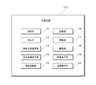
- It is a block diagram which shows the outline
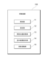
- FIG. 1 is a block diagram showing an outline of an exploration device 100 according to this embodiment.
- the exploration device 100 of this embodiment includes an irradiation unit 11 , a measurement unit 12 , an irradiation position change unit 13 , an aerial imaging display unit 14 and a projection variation unit 15 .
- the investigation device 100 is provided with a control section (not shown) that is connected to each section so as to be able to communicate with each other and controls each section.
- the irradiation unit 11 irradiates an external search position (predetermined position) with an electromagnetic wave or a particle beam based on a control signal from the control unit.
- Electromagnetic waves or particle beams to be irradiated are not limited, but are preferably ultraviolet light, visible light, infrared light, terahertz waves, millimeter waves, microwaves, alpha rays, beta rays or gamma rays.
- electromagnetic waves in that wavelength band when an object to be explored has a property of absorbing a specific wavelength band, it is preferable to use electromagnetic waves in that wavelength band.
- the specific configuration of the irradiation unit 11 is not limited, and known devices such as a semiconductor laser device, a LiDAR (Light Detection And Ranging) device, and an electromagnetic wave irradiation device can be used.
- Examples of objects to be explored with electromagnetic waves or particle beams irradiated from the irradiation unit 11 include exploration of explosives (C3, C4 explosives, etc.) by terahertz waves, biological exploration by infrared rays, and object exploration by visible light and image recognition. , material exploration by investigating heating and heat generation by millimeter waves, buried object exploration by microwaves, etc.
- a particle beam such as an alpha ray or a beta ray or a gamma ray to destroy or stop the function of an electronic device which is an object.
- an electronic device using an infrared light sensor is used as a target object, and a signal is transmitted by irradiating infrared light.
- the measurement unit 12 measures the electromagnetic waves reflected by the target or non-target, or other electromagnetic waves or reactions caused by electromagnetic wave absorption or particle beam collision by the target, and transmits them to the control unit.
- the measurement unit 12 is not limited to a specific configuration as long as it can detect the reaction caused by the electromagnetic wave or particle beam emitted from the irradiation unit 11, and a known device such as a light receiving element or radio wave measuring device can be used.
- the control unit of the exploration device 100 determines the presence or absence of the object in the irradiation area, the shape of the object, etc. as the irradiation area information.
- a known image recognition technique or object detection based on calculation of electromagnetic wave reflectance can be used.
- the irradiation position changing unit 13 changes the region irradiated with the electromagnetic wave or particle beam emitted from the irradiation unit 11 based on the control signal from the control unit.
- the specific configuration of the irradiation position changing unit 13 is not limited, it may be a motor device that mechanically changes the direction of the irradiation unit 11, a DMD (digital mirror device) that optically scans the electromagnetic waves irradiated from the irradiation unit 11, , a known device such as a device for controlling the directivity of electromagnetic waves can be used.
- the aerial image formation display unit 14 forms a real image or a virtual image of visible light in the air and displays it to the viewpoint.
- the specific configuration of the aerial image display unit 14 is not limited, a glasses-type HUD (Head Up Display) device using a waveguide and a diffraction grating, a HUD device using a retroreflector, or the like can be used.
- the aerial image display unit 14 it is preferable to use one capable of forming different images at a plurality of positions in the air (for example, JP 2021-047234 A, JP 2021-047234 A, 089396, Japanese Patent Application Laid-Open No. 2021-096284, etc.).
- the aerial image formation display unit 14 preferably has a configuration including an image irradiation unit that irradiates image irradiation light that is visible light, and an imaging optical unit that forms an image of the image irradiation light in the air.
- a laser light source, a liquid crystal display device, an organic EL display device, or the like can be used as the image irradiation unit.
- the imaging optical section includes an optical element that guides the image irradiation light emitted from the image irradiation section and projects the image irradiation light in the viewpoint direction so as to form an image in the air.
- the projection variation unit 15 sets a predetermined range as the search area, and when the search area is changed, the image forming position of the real image or the virtual image on the aerial image formation display unit 14 is changed in conjunction with the change in the search area. Change the position relative to the viewpoint.
- the aerial image display unit 14 has an image irradiation unit and an image formation optical unit
- the image irradiation unit and/or the image formation optical unit are mechanically driven to change the mutual device positions. good too.
- the display position of the image included in the image irradiation light may be relatively changed.
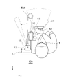
- FIG. 2 is a schematic diagram showing the investigation device 100 according to this embodiment.
- the irradiation unit 11, the measurement unit 12, and the irradiation position changing unit 13 are attached to the viewer's shoulder, and the spectacle-type aerial image formation display unit 14 and the projection variation unit 15 are attached to the viewer's head. is installed.
- the mounting position of each part is not limited to the example shown in FIG. 2, and each part may be mounted separately, or a plurality of parts may be housed in one housing and mounted collectively.
- the irradiation unit 11 irradiates electromagnetic waves EM having directivity in front of the viewer under the control of the control unit.
- electromagnetic wave EM an example using electromagnetic wave EM is shown here, the same applies to the case of irradiating particle beams.
- the irradiation position changing unit 13 changes the irradiation direction of the electromagnetic wave EM emitted from the irradiation unit 11 based on the control of the control unit.
- the control unit obtains the angle of view from the viewer's viewpoint e, and calculates in which direction the electromagnetic wave EM emitted from the irradiation unit 11 is positioned within the angle of view when the line-of-sight direction is viewed from the viewpoint e. .
- the control unit forms an indicator image A2, which is a virtual image or a real image, in the air, and superimposes it on the investigation position for display.
- control unit may set the range to be irradiated with the electromagnetic wave EM as the exploration area V1, and irradiate the electromagnetic wave EM only within the range of the exploration area V1.
- control unit calculates to which range the search area V1 corresponds within the angle of view from the viewpoint e. After that, the control unit forms an area presentation image A1, which is a virtual image or a real image, in the air, and displays the area presentation image A1 superimposed on the search area V1.
- control unit may change the position of the search area V1.
- the control unit recalculates the range of the exploration area V1 within the angle of view of the viewpoint e, recalculates the display position of the area presentation image A1, and determines the imaging position. change.
- the display position in normal aerial imaging is changed.
- the projection variation section 15 is used to move the aerial image formation display section 14.
- the search area In conjunction with the change of V1, the projection variation unit 15 changes the relative position of the image irradiation unit with respect to the imaging optical unit.
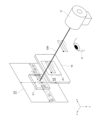
- FIG. 3 is a perspective view schematically showing the irradiation of electromagnetic waves EM or particle beams and the formation of images in the air.
- the entire range that can be irradiated with the electromagnetic wave EM using the irradiation position changing unit 13 is defined as an irradiation possible range V2.
- a predetermined range within the irradiable range V2 is set as the search area V1.
- the irradiation unit 11 irradiates the electromagnetic wave EM, and the irradiation position changing unit 13 scans the irradiation position of the electromagnetic wave EM within the investigation region V1.
- the aerial image formation display unit 14 superimposes the region presentation image A1 on the investigation region V1 and forms an image in the line-of-sight direction from the viewer's viewpoint e. Further, the aerial image display unit 14 superimposes and forms an indicator image A2 on the investigation position irradiated with the electromagnetic wave EM.
- the viewer can see the exploration area V1 irradiated with the electromagnetic wave EM and the area actually irradiated with the electromagnetic wave EM. It is possible to visually recognize the search position being superimposed on the background. Further, the area presentation image A1 and the indicator image A2 are formed in the air as a virtual image or a real image with a sense of depth, and the distance from the viewpoint e can be changed. You can more intuitively see the irradiation area of .
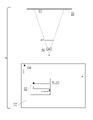
- FIG. 4 is a diagram showing the relationship between an irradiation range V2 for irradiation with electromagnetic waves or particle beams and the exploration area V1.
- a predetermined area of the irradiable range V2 is set as the search area V1 in this modified example as well.
- the area presentation image A1 is imaged at a position a predetermined distance away from the viewpoint e, and the indicator image A2 is imaged between the area presentation image A1 and the viewpoint e.
- the irradiation position changing unit 13 scans the entire irradiation possible range V2 with the electromagnetic wave EM at high speed.
- high speed means that the search position moves quickly within the search area V1 and the scanning interval is large.
- the aerial image formation display unit 14 may superimpose the indicator image A2 over the entire irradiation range V2. However, since the visibility of the indicator image A2 deteriorates in high-speed scanning over a wide area, the aerial image formation display unit 14 omits the image formation and superimposition of the area presentation image A1 and the indicator image A2 in the entire scanning process. may
- the control unit selects a predetermined range determined to have a high possibility of existence of the object as the search area. Set as V1.
- the irradiation position changing unit 13 scans the search region V1 with the electromagnetic wave EM as a detailed scanning step. In the scanning of the electromagnetic wave EM in the detailed scanning process, the movement of the search position is slower than in the overall scanning process, and the scanning interval is set smaller.
- the aerial imaging display unit 14 superimposes the area presentation image A1 on the investigation area V1 to form an image, and superimposes the indicator image A2 on the investigation position to form an image.
- the inside of the irradiable range V2 is searched at high speed in the overall scanning step, a predetermined region in which the object is likely to exist is set as the searching region V1, and the detailed scanning step is performed within the searching region V1. to explore.
- the accuracy of searching for the object while searching for the object in a wider range.
- the visibility of the search position is improved. can be improved.
- FIG. 5 is a block diagram showing an overview of the exploration device 110 according to this embodiment.
- FIG. 6 is a schematic diagram showing the investigation device 110 according to this embodiment.
- the exploration device 110 of this embodiment includes an irradiation unit 11, a measurement unit 12, an irradiation position change unit 13, an aerial imaging display unit 14, a projection variation unit 15, and an imaging unit 16. , a mounting section 17 , a drive section 18 , an image display section 19 and a remote control section 20 .
- the exploration device 110 also includes a power source 21 and a control section 22 .
- the imaging unit 16 captures an image in a predetermined position direction as a line-of-sight image.
- the specific configuration of the imaging unit 16 is not limited, and a known imaging device using an imaging element such as a CCD (Charge Coupled Device) sensor or a CMOS (Complementary MOS) sensor can be used.
- Information about the line-of-sight image captured by the imaging unit 16 is transmitted to the control unit 22 and the image display unit 19 .
- the mounting unit 17 is a portion that constitutes the housing of the moving body, and includes the irradiation unit 11, the measurement unit 12, the irradiation position changing unit 13, the aerial image formation display unit 14, the projection variation unit 15, the imaging unit 16, and the power source 21. and the control unit 22 are mounted.
- the shape of the mounting portion 17 is not limited, and various forms such as a humanoid robot, a drone that flies in the air, and a vehicle-like moving body can be used.
- the drive unit 18 generates power based on a control signal supplied from the outside, converts the generated power into motion, and moves the mounting unit 17 .
- the power generation mechanism of the drive unit 18 is not limited, and a known configuration such as a motor device that generates torque by electric power, an internal combustion engine, an external combustion engine, etc. can be used.
- the mechanism for converting the power of the drive unit 18 into motion is not limited, and known devices such as wheels, crawler tracks, multi-legged walking devices, propeller mechanisms, and jet engines can be used.
- the image display unit 19 is connected to the control unit 22 by wire or wirelessly so that information can be communicated, and displays the line-of-sight image captured by the imaging unit 16 .
- a specific configuration of the image display unit 19 is not limited, and a known device such as a liquid crystal display device or an organic EL display device can be used. Further, a touch panel type sensor or the like may be mounted on the image display section 19 and configured integrally with the remote control section 20 .
- the remote control unit 20 is connected to the control unit 22 by wire or wirelessly so that information can be communicated, and sends control signals to the drive unit 18 based on the operation of the operator.
- the specific configuration of the remote control unit 20 is not limited, and known devices such as a touch panel sensor, keyboard, mouse, button controller, and motion detection controller can be used.
- the power source 21 supplies energy for generating power in the drive section 18 .
- a specific configuration of the power source 21 is not limited, and a known power source such as a commercial power source, a secondary battery, a gasoline storage chamber, a hydrogen storage chamber, and a fuel cell can be used.
- the control unit 22 is connected to each unit of the exploration device 110 so that information can be communicated by wire or wirelessly, executes a predetermined procedure according to a predetermined program, and controls the operation of each unit.
- a specific configuration of the control unit 22 is not limited, and a conventionally known computer device can be used.
- the control unit 22 may include a memory device, a recording medium, a communication device, and the like.
- the aerial image formation display unit 14 superimposes the irradiation position of the electromagnetic wave EM and the indicator image A2, and causes the imaging unit 16 to form a real image or a virtual image. Further, when the search area V1 is set, the aerial imaging display unit 14 superimposes the search area V1 and the area presentation image A1 to form a real image or a virtual image on the imaging unit 16 .
- the imaging unit 16 captures a forward line-of-sight image via the aerial imaging display unit 14 and displays the line-of-sight image on the image display unit 19 .
- the line-of-sight image is obtained by superimposing the area presentation image A1 and the indicator image A2 on the background through the aerial image forming display unit 14 .
- the operator operates the moving object using the remote control unit 20 while viewing the line-of-sight image displayed on the image display unit 19 .
- the image formation timing of the area presentation image A1 and the indicator image A2 may be synchronized with the change of the irradiation position by the irradiation position changing unit 13, and either the change of the irradiation position or the image formation timing may be changed for a predetermined time.
- Image A1 and indicator image A2 may be imaged.
- the exploration device 110 is attached to the mobile object, and the operator operates the mobile object with the remote control unit 20 while viewing the line-of-sight image displayed on the image display unit 19 .
- the area presentation image A1 and the indicator image A2 imaged in the air are captured by the imaging unit 16, the area presentation image A1 and the indicator image A2 are superimposed on the background in the line-of-sight image to give a sense of depth. be done. Therefore, the line-of-sight image has a high sense of realism as if a person were actually viewing the front at the position of the imaging unit 16 .
- Reference Signs List 100 110 Exploring device 11 Irradiation unit 12 Measurement unit 13 Irradiation position change unit 14 Aerial imaging display unit 15 Projection variation unit 16 Imaging unit 17 Mounting unit 18 Driving unit 19 Image display unit 20 Remote control unit 21 Power source 22 Control unit V1 Search area V2 Irradiable range A1 Area presentation image A2 Indicator image
Landscapes
- Physics & Mathematics (AREA)
- Engineering & Computer Science (AREA)
- General Physics & Mathematics (AREA)
- General Engineering & Computer Science (AREA)
- High Energy & Nuclear Physics (AREA)
- Optics & Photonics (AREA)
- Computer Networks & Wireless Communication (AREA)
- Electromagnetism (AREA)
- Radar, Positioning & Navigation (AREA)
- Remote Sensing (AREA)
- Geophysics And Detection Of Objects (AREA)
Abstract
装置(100)であって、所定の位置に対して電磁波または粒子線を照射する照射部(11)と、所定の位置から反射された電磁波または粒子線衝突の反応を測定する測定部(12)と、実像または虚像を結像させて空中に表示する空中結像表示部(14)とを備え、空間結像表示部(14)は、実像または虚像を所定の位置に重ね合わせて結像させることを特徴とする。
Description
本開示は、装置に関し、特に電磁波または粒子線を照射する範囲を表示する装置に関する。
従来から、対象物を探索するためにレーザ光や電磁波を照射し、反射した光や電磁波を測定することで、対象物を認識して特定する探索装置が提案されている(例えば特許文献1を参照)。また、人間の到達が困難な場所や空間での作業では、探索装置が搭載された移動体を遠隔操作して、移動体に取り付けられた照射装置からレーザ光や電磁波を照射することが提案されている。
このような探索装置では、探索範囲の領域に照射するレーザ光や電磁波は可視光ではなく、人間の目ではどの範囲を探索しているかを直接視認することができなかった。そのため、どの領域に対してレーザ光や電磁波が照射されているかを認識するために、画像表示装置を用いて照射領域を示す画像を背景に重ね合わせることも提案されている。
しかし、画面を通しての視認では画面上の表示内容と現実空間との関連性が乏しく、直感的で臨場感のある方法で照射領域を視認することは困難だった。照射領域をより直感的に視認することができれば、対象物を検知した後の動作を迅速に行うことや、移動体の遠隔操作をより迅速かつ適切に行うことが可能となる。
そこで本開示は、上記従来の問題点に鑑みなされたものであり、レーザ光や電磁波または粒子線の照射領域を直感的に視認できる装置を提供することを目的とする。
上記課題を解決するために、本開示の装置は、所定の位置に対して電磁波または粒子線を照射する照射部と、前記所定の位置から反射された前記電磁波または前記粒子線衝突の反応を測定する測定部と、実像または虚像を結像させて空中に表示する空中結像表示部とを備え、前記空間結像表示部は、前記実像または虚像を前記所定の位置に重ね合わせて結像させることを特徴とする。
このような本開示の装置では、電磁波または粒子線を照射する位置に重ね合わせて、空中結像表示部で実像または虚像を空中に結像させることで、電磁波または粒子線の照射領域を直感的に視認できる。
また、本開示の一態様では、前記所定の位置方向の画像を視線画像として撮像する撮像部と、前記照射部、前記測定部、前記撮像部および前記空中結像表示部を搭載する搭載部と、前記搭載部を移動させる駆動部とを備え、前記空中結像表示部は、前記撮像部に対して前記実像または虚像を結像させる。
また、本開示の一態様では、前記視線画像を表示する画像表示部と、前記駆動部を遠隔操作する遠隔操作部とを備える。
また、本開示の一態様では、所定の範囲を探査領域とし、前記所定の位置を前記探査領域内で変更する照射位置変更部を備え、前記空中結像表示部は、領域提示画像を前記探査領域に重ね合わせて結像させる。
また、本開示の一態様では、前記空中結像表示部は、前記領域提示画像を含んだ画像照射光を照射する画像照射部と、前記画像照射光を空中に結像させる結像光学部とを備え、前記探査領域の変化と連動して、前記結像光学部に対する前記画像照射部の相対位置を変化させる投影変動部を備える。
また、本開示の一態様では、前記照射部が照射する前記電磁波または前記粒子線は、紫外光、可視光、赤外光、テラヘルツ波、ミリ波、マイクロ波、アルファ線、ベータ線またはガンマ線の何れかである。
本開示では、レーザ光や電磁波または粒子線の照射領域を直感的に視認できる装置を提供することができる。
(第1実施形態)
以下、本開示の実施形態について、図面を参照して詳細に説明する。各図面に示される同一または同等の構成要素、部材、処理には、同一の符号を付すものとし、適宜重複した説明は省略する。図1は、本実施形態に係る探査装置100の概要を示すブロック図である。図1に示すように、本実施形態の探査装置100は、照射部11と、測定部12と、照射位置変更部13と、空中結像表示部14と、投影変動部15を備えている。また、探査装置100には各部と情報通信可能に接続されて、各部を制御する制御部を備えている(図示省略)。
以下、本開示の実施形態について、図面を参照して詳細に説明する。各図面に示される同一または同等の構成要素、部材、処理には、同一の符号を付すものとし、適宜重複した説明は省略する。図1は、本実施形態に係る探査装置100の概要を示すブロック図である。図1に示すように、本実施形態の探査装置100は、照射部11と、測定部12と、照射位置変更部13と、空中結像表示部14と、投影変動部15を備えている。また、探査装置100には各部と情報通信可能に接続されて、各部を制御する制御部を備えている(図示省略)。
照射部11は、制御部からの制御信号に基づいて、外部の探査位置(所定の位置)に対して電磁波または粒子線を照射する。照射する電磁波または粒子線は限定されないが、紫外光、可視光、赤外光、テラヘルツ波、ミリ波、マイクロ波、アルファ線、ベータ線またはガンマ線の何れかであることが好ましい。特に、探査対象である対象物が特定の波長帯域を吸収する性質を備えている場合には、当該波長帯域の電磁波を用いることが好ましい。また、照射部11の具体的構成も限定されず、半導体レーザ装置やLiDAR(Light Detection And Ranging)装置、電磁波照射装置等の公知のものを用いることができる。
照射部11から照射される電磁波または粒子線と探査する対象物の例としては、テラヘルツ波による爆発物(C3,C4爆薬等)の探査、赤外線による生物探査、可視光と画像認識による物体の探査、ミリ波による加熱とそれによる発熱を調査することによる物質探査、マイクロ波による埋設物探査などが挙げられる。また、対象物の探査以外の用途としては、アルファ線やベータ線等の粒子線やガンマ線を照射して対象物である電子機器を破壊または機能停止させる用途が挙げられる。また、赤外光センサを用いた電子機器を対象物として、赤外光を照射して信号を伝達する用途例も挙げられる。
測定部12は、対象物または非対象物によって反射された電磁波、または、対象物による電磁波吸収や粒子線衝突によって生じる他の電磁波や反応を測定し、制御部に伝達する。測定部12は、照射部11から照射される電磁波または粒子線による反応を検出できれば具体的構成は限定されず、受光素子や電波測定器等の公知のものを用いることができる。測定部12での測定結果に基づいて、探査装置100の制御部では照射領域情報として照射領域における対象物の有無や、対象物の形状等を判定する。制御部での照射領域情報の判定には、公知の画像認識技術や電磁波反射率の算出による対象物検知を用いることができる。
照射位置変更部13は、制御部からの制御信号に基づいて、照射部11から照射される電磁波または粒子線の照射される領域を変更する。照射位置変更部13の具体的構成は限定されないが、照射部11の向きを機械的に変更するモータ装置や、照射部11から照射された電磁波を光学的に走査するDMD(デジタルミラーデバイス)や、電磁波の指向性を制御する装置等の公知のものを用いることができる。
空中結像表示部14は、可視光の実像または虚像を空中に結像させて視点に対して表示する。空中結像表示部14の具体的構成は限定されないが、導波路と回折格子を用いた眼鏡型のHUD(Head Up Display)装置や、再帰反射板を用いたHUD装置等を用いることができる。空中結像表示部14としては、空中における複数の位置に異なる画像を結像することが可能なものを用いることが好ましい(例えば、日本国特開2021-047234号公報、日本国特開2021-089396号公報、日本国特開2021-096284号公報等を参照)。
また、空中結像表示部14は、可視光である画像照射光を照射する画像照射部と、画像照射光を空中に結像させる結像光学部とを備える構成とすることが好ましい。画像照射部はレーザ光源や液晶表示装置、有機EL表示装置等が挙げられる。結像光学部は、画像照射部から照射された画像照射光を導波するとともに、空中で結像するように視点方向に画像照射光を投影する光学要素を備える。
投影変動部15は、所定の範囲を探査領域と設定し、探査領域が変更された場合に、探査領域の変化と連動して、空中結像表示部14での実像または虚像の結像位置と視点との位置を相対的に変化させる。空中結像表示部14が画像照射部と結像光学部とを備えている場合には、画像照射部または/および結像光学部を機械的に駆動して、互いの装置位置を変化させるとしてもよい。または、画像照射光に含まれる画像の表示位置を相対的に変化させるとしてもよい。
図2は、本実施形態に係る探査装置100について示す模式図である。図2に示した例では、視聴者の肩に照射部11、測定部12および照射位置変更部13が装着され、視聴者の頭部に眼鏡型の空中結像表示部14および投影変動部15が装着されている。各部の装着位置は図2に示した例に限定されず、また、各部が別体として装着されても、複数部分を一つの筐体に収容してまとめて装着されてもよい。
図2に示したように、照射部11は制御部の制御に基づいて指向性を持った電磁波EMを視聴者の前方に照射する。ここでは、電磁波EMを用いた例を示しているが、粒子線を照射する場合も同様である。また、照射位置変更部13は、制御部の制御に基づいて照射部11から照射される電磁波EMの照射方向を変更する。制御部は、視聴者の視点eからの画角を求め、照射部11から照射される電磁波EMが、視点eから視線方向を視認した場合の画角内においてどの方向に位置するかを算出する。その後、制御部は、虚像または実像であるインジケータ画像A2を空中に結像して、探査位置に重ね合わせて表示する。
また、制御部は、電磁波EMを照射する範囲を探査領域V1として設定して、探査領域V1の範囲内に対してのみ、電磁波EMを照射するようにしてもよい。この場合には、制御部は、視点eからの画角内において探査領域V1をどの範囲に対応するかを算出する。その後、制御部は、虚像または実像である領域提示画像A1を空中に結像して、探査領域V1に重ね合わせて表示する。
また、制御部は、探査領域V1の位置を変更してもよい。探査領域V1の位置を変更した場合には、制御部は視点eの画角内における探査領域V1の範囲を再度算出するとともに、領域提示画像A1の表示位置を再度算出して、結像位置を変化させる。ここで、空中結像表示部14の表示可能領域内において、探査領域V1および領域提示画像A1を変化させる場合には、通常の空中結像における表示位置の変更を行う。空中結像表示部14の表示可能領域を超えて、探査領域V1および領域提示画像A1を変化させる場合には、投影変動部15を用いて空中結像表示部14の移動を行う。
空中結像表示部14として、領域提示画像A1を含んだ画像照射光を照射する画像照射部と、画像照射光を空中に結像させる結像光学部との組み合わせを用いる場合には、探査領域V1の変化と連動して、投影変動部15で結像光学部に対する画像照射部の相対位置を変化させる。
図3は、電磁波EMまたは粒子線の照射と画像の空中への結像を模式的に示す斜視図である。照射位置変更部13を用いて電磁波EMを照射可能な全範囲を、照射可能範囲V2とする。照射可能範囲V2内における所定の範囲が、探査領域V1として設定されている。照射部11は電磁波EMを照射し、照射位置変更部13が電磁波EMの照射位置を探査領域V1内で走査する。空中結像表示部14は、視聴者の視点eから視線方向において、領域提示画像A1を探査領域V1に重ね合わせて結像する。また空中結像表示部14は、電磁波EMが照射されている探査位置にインジケータ画像A2を重ね合わせて結像する。
空中結像表示部14を用いて、領域提示画像A1およびインジケータ画像A2を空中に結像して表示することで、視聴者は電磁波EMが照射される探査領域V1と、実際に電磁波EMが照射されている探査位置を、背景と重ね合わせて視認することができる。また、領域提示画像A1およびインジケータ画像A2は、奥行き感を持った虚像または実像として空中に結像され、視点eからの距離も変更可能であるため、実空間を背景として重ね合わせることで電磁波EMの照射領域をより直感的に視認できる。
(第1実施形態の変形例)
次に、第1実施形態の変形例について図4を用いて説明する。第1実施形態では探査領域V1に限定して電磁波EMを照射したが、本変形例では照射可能範囲V2への照射も行う。図4は、電磁波または粒子線を照射する照射可能範囲V2と探査領域V1との関係を示す図である。
次に、第1実施形態の変形例について図4を用いて説明する。第1実施形態では探査領域V1に限定して電磁波EMを照射したが、本変形例では照射可能範囲V2への照射も行う。図4は、電磁波または粒子線を照射する照射可能範囲V2と探査領域V1との関係を示す図である。
図4の上段に示すように、本変形例でも照射可能範囲V2の所定の領域が、探査領域V1に設定される。探査領域V1に対応して、視点eから所定の距離離れた位置に領域提示画像A1が結像され、領域提示画像A1と視点eの間にインジケータ画像A2が結像される。本変形例では全体スキャン工程として、照射位置変更部13は、電磁波EMを照射可能範囲V2全体で高速に走査する。ここで高速とは、探査領域V1内での探査位置の移動が速く、走査間隔が大きいことを意味する。全体スキャン工程において、空中結像表示部14が照射可能範囲V2内全体でインジケータ画像A2を重ね合わせるとしてもよい。しかし、広範囲での高速な走査では、インジケータ画像A2の視認性が低下するため、全体スキャン工程では、空中結像表示部14は領域提示画像A1とインジケータ画像A2の結像と重ね合わせを省略してもよい。
全体スキャン工程で照射可能範囲V2内への電磁波EMの照射と、測定部12での測定を行った後、制御部は、対象物の存在する可能性が高いと判断した所定の範囲を探査領域V1として設定する。探査領域V1を設定した後に、詳細スキャン工程として、照射位置変更部13は、電磁波EMを探査領域V1内で走査する。詳細スキャン工程での電磁波EMの走査は、全体スキャン工程よりも探査位置の移動が遅く、走査間隔も小さく設定される。詳細スキャン工程では、空中結像表示部14は探査領域V1に領域提示画像A1を重ね合わせて結像し、探査位置にインジケータ画像A2を重ね合わせて結像する。
本変形例では、全体スキャン工程で照射可能範囲V2内を高速に探査し、対象物の存在する可能性が高い所定の領域を探査領域V1として設定し、探査領域V1内を詳細スキャン工程で詳細に探査する。これにより、より広い範囲での対象物の探査を実行しつつ、対象物の探査精度を向上させることができる。また、全体スキャン工程では領域提示画像A1とインジケータ画像A2の結像を省略し、詳細スキャン工程でのみ領域提示画像A1とインジケータ画像A2を重ね合わせて結像することで、探査位置の視認性を向上させることができる。
(第2実施形態)
次に、本開示の第2実施形態について図5,図6を用いて説明する。第1実施形態と重複する内容は説明を省略する。第1実施形態では視聴者の身体に探査装置を装着した例を示したが、本実施形態では移動体に探査装置を装着して遠隔操作する。図5は、本実施形態に係る探査装置110の概要を示すブロック図である。図6は、本実施形態に係る探査装置110について示す模式図である。図5に示すように、本実施形態の探査装置110は、照射部11と、測定部12と、照射位置変更部13と、空中結像表示部14と、投影変動部15と、撮像部16と、搭載部17と、駆動部18と、画像表示部19と、遠隔操作部20を備えている。また、探査装置110は動力源21と制御部22を備えている。
次に、本開示の第2実施形態について図5,図6を用いて説明する。第1実施形態と重複する内容は説明を省略する。第1実施形態では視聴者の身体に探査装置を装着した例を示したが、本実施形態では移動体に探査装置を装着して遠隔操作する。図5は、本実施形態に係る探査装置110の概要を示すブロック図である。図6は、本実施形態に係る探査装置110について示す模式図である。図5に示すように、本実施形態の探査装置110は、照射部11と、測定部12と、照射位置変更部13と、空中結像表示部14と、投影変動部15と、撮像部16と、搭載部17と、駆動部18と、画像表示部19と、遠隔操作部20を備えている。また、探査装置110は動力源21と制御部22を備えている。
撮像部16は、所定の位置方向の画像を視線画像として撮像する。撮像部16の具体的構成は限定されず、CCD(Charge Coupled Device)センサやCMOS(Complementary MOS)センサ等の撮像素子を用いた公知の撮像装置を用いることができる。撮像部16が撮像した視線画像の情報は、制御部22および画像表示部19に伝達される。
搭載部17は、移動体の筐体を構成する部分であり、照射部11、測定部12、照射位置変更部13、空中結像表示部14、投影変動部15、撮像部16、動力源21および制御部22を搭載する。搭載部17の形状は限定されず、例えば人型のロボットや、空中を飛行するドローン、車両形状の移動体など各種形態を用いることができる。
駆動部18は、外部から供給される制御信号に基づいて動力を発生させ、発生した動力を運動に変換して、搭載部17を移動させる。駆動部18の動力発生機構は限定されず、電力によってトルクを発生するモータ装置や、内燃機関、外燃機関等の公知の構成を用いることができる。また、駆動部18の動力を運動に変換する機構も限定されず、車輪や無限軌道装置、多足歩行装置、プロペラ機構、ジェットエンジン等の公知のものを用いることができる。
画像表示部19は、制御部22との間で有線または無線によって情報通信可能に接続されており、撮像部16が撮像した視線画像を表示する。画像表示部19の具体的構成は限定されず、液晶表示装置や有機EL表示装置等の公知のものを用いることができる。また、画像表示部19にタッチパネル式センサ等を搭載して、遠隔操作部20と一体に構成してもよい。
遠隔操作部20は、制御部22との間で有線または無線によって情報通信可能に接続されており、作業者の操作に基づいて、駆動部18に対して制御信号を送出する。遠隔操作部20の具体的構成は限定されず、タッチパネル式センサ、キーボード、マウス、ボタン式コントローラ、モーション検知式コントローラ等の公知のものを用いることができる。
動力源21は、駆動部18で動力を発生させるためのエネルギーを供給する。動力源21の具体的構成は限定されず、商用電源、二次電池、ガソリン貯蔵室、水素貯蔵室、燃料電池等の公知のものを用いることができる。
制御部22は、探査装置110の各部と有線または無線で情報通信可能に接続され、予め定められたプログラムに従って所定の手順を実行し、各部の動作を制御する。制御部22の具体的構成は限定されず、従来公知のコンピュータ装置を用いることができる。また、制御部22にはメモリ装置や記録媒体、通信装置等を備えるとしてもよい。
本実施形態では、空中結像表示部14は、電磁波EMの照射位置とインジケータ画像A2を重ね合わせて、撮像部16に対して実像または虚像を結像させる。また、探査領域V1を設定した場合には、空中結像表示部14は、探査領域V1と領域提示画像A1を重ね合わせて撮像部16に対して実像または虚像を結像させる。
撮像部16は、空中結像表示部14を介して前方の視線画像を撮像し、画像表示部19に視線画像を表示する。このとき、視線画像には空中結像表示部14を介した背景に、領域提示画像A1およびインジケータ画像A2が重ね合わされたものとなる。作業者は、画像表示部19に表示された視線画像を視認しながら、遠隔操作部20を用いて移動体を操作する。ここで、領域提示画像A1およびインジケータ画像A2の結像タイミングは、照射位置変更部13による照射位置の変更と同期していてもよく、照射位置の変更と結像タイミングのどちらかを所定時間だけ異ならせるとしてもよい。一例としては、対象物が電磁波EMまたは粒子線によって敏感に熱的な反応を示す場合には、電磁波EMまたは粒子線の対象物への照射で反応が終了する数ミリ秒から数秒後に、領域提示画像A1およびインジケータ画像A2を結像してもよい。
本実施形態では、移動体に探査装置110を装着して、作業者が、画像表示部19に表示された視線画像を視認しながら、遠隔操作部20で移動体を操作する。また、空中に結像された領域提示画像A1およびインジケータ画像A2を、撮像部16で撮像するため、視線画像では、領域提示画像A1とインジケータ画像A2が奥行き感を持って背景と重ね合わせて表示される。したがって、視線画像は、現実に撮像部16の位置で人間が前方を視認しているかのような臨場感の高いものとなる。これにより、人間が立ち入ることが困難な場所においても、作業者の安全を確保しつつ精度の高い対象物探査を行うことができる。
本開示は上述した各実施形態に限定されるものではなく、請求項に示した範囲で種々の変更が可能であり、異なる実施形態にそれぞれ開示された技術的手段を適宜組み合わせて得られる実施形態についても本開示の技術的範囲に含まれる。
本出願は、2021年8月20日出願の日本特許出願(特願2021-135243)に基づくものであり、その内容はここに参照として取り込まれる。
本開示によれば、レーザ光や電磁波または粒子線の照射領域を直感的に視認できる装置を提供することができる。
100,110…探査装置
11…照射部
12…測定部
13…照射位置変更部
14…空中結像表示部
15…投影変動部
16…撮像部
17…搭載部
18…駆動部
19…画像表示部
20…遠隔操作部
21…動力源
22…制御部
V1…探査領域
V2…照射可能範囲
A1…領域提示画像
A2…インジケータ画像
11…照射部
12…測定部
13…照射位置変更部
14…空中結像表示部
15…投影変動部
16…撮像部
17…搭載部
18…駆動部
19…画像表示部
20…遠隔操作部
21…動力源
22…制御部
V1…探査領域
V2…照射可能範囲
A1…領域提示画像
A2…インジケータ画像
Claims (6)
- 所定の位置に対して電磁波または粒子線を照射する照射部と、
前記所定の位置から反射された前記電磁波または前記粒子線衝突の反応を測定する測定部と、
実像または虚像を結像させて空中に表示する空中結像表示部とを備え、
前記空間結像表示部は、前記実像または虚像を前記所定の位置に重ね合わせて結像させることを特徴とする装置。 - 前記所定の位置方向の画像を視線画像として撮像する撮像部と、
前記照射部、前記測定部、前記撮像部および前記空中結像表示部を搭載する搭載部と、
前記搭載部を移動させる駆動部とを備え、
前記空中結像表示部は、前記撮像部に対して前記実像または虚像を結像させることを特徴とする、請求項1に記載の装置。 - 前記視線画像を表示する画像表示部と、
前記駆動部を遠隔操作する遠隔操作部とを備えることを特徴とする、請求項2に記載の装置。 - 所定の範囲を探査領域とし、
前記所定の位置を前記探査領域内で変更する照射位置変更部を備え、
前記空中結像表示部は、領域提示画像を前記探査領域に重ね合わせて結像させることを特徴とする、請求項1から3の何れか一つに記載の装置。 - 前記空中結像表示部は、前記領域提示画像を含んだ画像照射光を照射する画像照射部と、
前記画像照射光を空中に結像させる結像光学部とを備え、
前記探査領域の変化と連動して、前記結像光学部に対する前記画像照射部の相対位置を変化させる投影変動部を備えることを特徴とする、請求項4に記載の装置。 - 前記照射部が照射する前記電磁波または前記粒子線は、紫外光、可視光、赤外光、テラヘルツ波、ミリ波、マイクロ波、アルファ線、ベータ線またはガンマ線の何れかであることを特徴とする、請求項1から3の何れか一つに記載の装置。
Applications Claiming Priority (2)
| Application Number | Priority Date | Filing Date | Title |
|---|---|---|---|
| JP2021-135243 | 2021-08-20 | ||
| JP2021135243A JP2023029129A (ja) | 2021-08-20 | 2021-08-20 | 装置 |
Publications (1)
| Publication Number | Publication Date |
|---|---|
| WO2023021992A1 true WO2023021992A1 (ja) | 2023-02-23 |
Family
ID=85239490
Family Applications (1)
| Application Number | Title | Priority Date | Filing Date |
|---|---|---|---|
| PCT/JP2022/029798 Ceased WO2023021992A1 (ja) | 2021-08-20 | 2022-08-03 | 装置 |
Country Status (2)
| Country | Link |
|---|---|
| JP (1) | JP2023029129A (ja) |
| WO (1) | WO2023021992A1 (ja) |
Citations (5)
| Publication number | Priority date | Publication date | Assignee | Title |
|---|---|---|---|---|
| JP2005021453A (ja) * | 2003-07-03 | 2005-01-27 | Toshiba Corp | 治療線照射装置 |
| JP2007030673A (ja) * | 2005-07-26 | 2007-02-08 | Fujitsu Ten Ltd | 車両用表示装置 |
| JP2015146009A (ja) * | 2014-01-31 | 2015-08-13 | 有希 前田 | 結像光学素子 |
| JP2017531178A (ja) * | 2014-09-10 | 2017-10-19 | ファロ テクノロジーズ インコーポレーテッド | 環境を光学的にスキャンし測定するためのデバイスおよび方法ならびに制御の方法 |
| US20200141695A1 (en) * | 2018-09-03 | 2020-05-07 | Meprolight (1990) Ltd. | System and method for displaying an aiming vector of a firearm |
-
2021
- 2021-08-20 JP JP2021135243A patent/JP2023029129A/ja active Pending
-
2022
- 2022-08-03 WO PCT/JP2022/029798 patent/WO2023021992A1/ja not_active Ceased
Patent Citations (5)
| Publication number | Priority date | Publication date | Assignee | Title |
|---|---|---|---|---|
| JP2005021453A (ja) * | 2003-07-03 | 2005-01-27 | Toshiba Corp | 治療線照射装置 |
| JP2007030673A (ja) * | 2005-07-26 | 2007-02-08 | Fujitsu Ten Ltd | 車両用表示装置 |
| JP2015146009A (ja) * | 2014-01-31 | 2015-08-13 | 有希 前田 | 結像光学素子 |
| JP2017531178A (ja) * | 2014-09-10 | 2017-10-19 | ファロ テクノロジーズ インコーポレーテッド | 環境を光学的にスキャンし測定するためのデバイスおよび方法ならびに制御の方法 |
| US20200141695A1 (en) * | 2018-09-03 | 2020-05-07 | Meprolight (1990) Ltd. | System and method for displaying an aiming vector of a firearm |
Also Published As
| Publication number | Publication date |
|---|---|
| JP2023029129A (ja) | 2023-03-03 |
Similar Documents
| Publication | Publication Date | Title |
|---|---|---|
| US20250080700A1 (en) | Rotating lidar with co-aligned imager | |
| US10877281B2 (en) | Compact optical system with MEMS scanners for image generation and object tracking | |
| US8994819B2 (en) | Integrated optical detection system | |
| EP3274737B1 (en) | Methods and systems for lidar optics alignment | |
| US8605011B2 (en) | Virtual viewfinder on full windshield head-up display | |
| US20200033474A1 (en) | Lidar system with flexible scan parameters | |
| JPWO2011111201A1 (ja) | 画像位置調整装置 | |
| CN105247414B (zh) | 影像投射装置 | |
| CN110346815A (zh) | 具有多个光检测和测距装置(lidar)的车辆 | |
| CN104142505A (zh) | 具有目标感测单元用于目标跟踪和取向检测的激光跟踪仪 | |
| WO2016118369A1 (en) | Applying real world scale to virtual content | |
| US12607729B2 (en) | Test system for testing a LIDAR device | |
| JP2014126468A (ja) | 中継機を用いたレーザ照射システム | |
| JP2016006447A (ja) | 画像表示装置 | |
| JP2024546427A5 (ja) | ||
| CN118362046A (zh) | 基于双电光频率梳的激光跟踪干涉空间坐标测量系统和方法 | |
| WO2023021992A1 (ja) | 装置 | |
| CN111766949B (zh) | 三维图像显示设备、显示方法、电子设备以及存储介质 | |
| JP6358982B2 (ja) | 遠隔操作装置及び遠隔操作方法 | |
| JP6501444B2 (ja) | プロジェクション装置を備えた、とりわけ通信機器である電子機器、および、電子機器の動作方法 | |
| CN214202336U (zh) | 触控反馈系统和终端设备 | |
| CN117452433B (zh) | 基于单点单光子探测器的360度三维成像装置及方法 | |
| JP7724129B2 (ja) | レーザ照射システム | |
| WO2026086238A1 (zh) | 安检机器人设备 | |
| CN119078878A (zh) | 车辆野外探索自动驾驶系统、装置和车辆 |
Legal Events
| Date | Code | Title | Description |
|---|---|---|---|
| 121 | Ep: the epo has been informed by wipo that ep was designated in this application |
Ref document number: 22858313 Country of ref document: EP Kind code of ref document: A1 |
|
| NENP | Non-entry into the national phase |
Ref country code: DE |
|
| 122 | Ep: pct application non-entry in european phase |
Ref document number: 22858313 Country of ref document: EP Kind code of ref document: A1 |