WO2023021743A1 - 情報処理装置、情報処理方法およびプログラム - Google Patents
情報処理装置、情報処理方法およびプログラム Download PDFInfo
- Publication number
- WO2023021743A1 WO2023021743A1 PCT/JP2022/008814 JP2022008814W WO2023021743A1 WO 2023021743 A1 WO2023021743 A1 WO 2023021743A1 JP 2022008814 W JP2022008814 W JP 2022008814W WO 2023021743 A1 WO2023021743 A1 WO 2023021743A1
- Authority
- WO
- WIPO (PCT)
- Prior art keywords
- information processing
- information
- terminal
- host terminal
- interactivity
- Prior art date
- Legal status (The legal status is an assumption and is not a legal conclusion. Google has not performed a legal analysis and makes no representation as to the accuracy of the status listed.)
- Ceased
Links
Images












Classifications
-
- H—ELECTRICITY
- H04—ELECTRIC COMMUNICATION TECHNIQUE
- H04L—TRANSMISSION OF DIGITAL INFORMATION, e.g. TELEGRAPHIC COMMUNICATION
- H04L12/00—Data switching networks
- H04L12/02—Details
- H04L12/16—Arrangements for providing special services to substations
- H04L12/18—Arrangements for providing special services to substations for broadcast or conference, e.g. multicast
- H04L12/1813—Arrangements for providing special services to substations for broadcast or conference, e.g. multicast for computer conferences, e.g. chat rooms
-
- G—PHYSICS
- G06—COMPUTING OR CALCULATING; COUNTING
- G06F—ELECTRIC DIGITAL DATA PROCESSING
- G06F3/00—Input arrangements for transferring data to be processed into a form capable of being handled by the computer; Output arrangements for transferring data from processing unit to output unit, e.g. interface arrangements
- G06F3/01—Input arrangements or combined input and output arrangements for interaction between user and computer
-
- G—PHYSICS
- G06—COMPUTING OR CALCULATING; COUNTING
- G06F—ELECTRIC DIGITAL DATA PROCESSING
- G06F3/00—Input arrangements for transferring data to be processed into a form capable of being handled by the computer; Output arrangements for transferring data from processing unit to output unit, e.g. interface arrangements
- G06F3/01—Input arrangements or combined input and output arrangements for interaction between user and computer
- G06F3/048—Interaction techniques based on graphical user interfaces [GUI]
- G06F3/0481—Interaction techniques based on graphical user interfaces [GUI] based on specific properties of the displayed interaction object or a metaphor-based environment, e.g. interaction with desktop elements like windows or icons, or assisted by a cursor's changing behaviour or appearance
-
- G—PHYSICS
- G06—COMPUTING OR CALCULATING; COUNTING
- G06F—ELECTRIC DIGITAL DATA PROCESSING
- G06F3/00—Input arrangements for transferring data to be processed into a form capable of being handled by the computer; Output arrangements for transferring data from processing unit to output unit, e.g. interface arrangements
- G06F3/14—Digital output to display device ; Cooperation and interconnection of the display device with other functional units
-
- G—PHYSICS
- G09—EDUCATION; CRYPTOGRAPHY; DISPLAY; ADVERTISING; SEALS
- G09B—EDUCATIONAL OR DEMONSTRATION APPLIANCES; APPLIANCES FOR TEACHING, OR COMMUNICATING WITH, THE BLIND, DEAF OR MUTE; MODELS; PLANETARIA; GLOBES; MAPS; DIAGRAMS
- G09B5/00—Electrically-operated educational appliances
- G09B5/06—Electrically-operated educational appliances with both visual and audible presentation of the material to be studied
- G09B5/065—Combinations of audio and video presentations, e.g. videotapes, videodiscs, television systems
-
- H—ELECTRICITY
- H04—ELECTRIC COMMUNICATION TECHNIQUE
- H04L—TRANSMISSION OF DIGITAL INFORMATION, e.g. TELEGRAPHIC COMMUNICATION
- H04L67/00—Network arrangements or protocols for supporting network services or applications
-
- H—ELECTRICITY
- H04—ELECTRIC COMMUNICATION TECHNIQUE
- H04N—PICTORIAL COMMUNICATION, e.g. TELEVISION
- H04N7/00—Television systems
- H04N7/14—Systems for two-way working
- H04N7/15—Conference systems
Definitions
- the present disclosure relates to an information processing device, an information processing method, and a program.
- a system in which audio and video are transmitted and received between a plurality of terminal devices connected to each other in a predetermined network (see Patent Document 1, for example). Such a system enables remote meetings, lectures, live distribution of contents, and the like.
- One object of the present disclosure is to provide an information processing device, an information processing method, and a program that enable smooth communication between terminals.
- the present disclosure for example, Acquiring information about interactivity strength based on arrangement information indicating a relationship between a plurality of information processing terminals, and obtaining an output form in an output unit of at least one information processing terminal among the plurality of information processing terminals based on the interactivity strength is an information processing device including a control unit that performs control to change the
- a control unit acquires information about interactivity strength based on arrangement information indicating a relationship between a plurality of information processing terminals, and outputs an output of at least one information processing terminal among the plurality of information processing terminals based on the bidirectional strength.
- This is an information processing method for performing control to change the output form in a unit.
- a control unit acquires information about interactivity strength based on arrangement information indicating a relationship between a plurality of information processing terminals, and outputs an output of at least one information processing terminal among the plurality of information processing terminals based on the bidirectional strength. It is a program for causing a computer to execute an information processing method for controlling to change an output form in a unit.
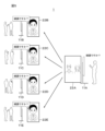
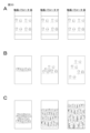
- FIG. 1 is a diagram that is referenced when describing issues to be considered in the present disclosure.
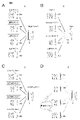
- Figures 2A-2D are diagrams that are referenced when discussing issues to be considered in this disclosure.
- FIG. 3 shows a configuration example of a video communication system according to one embodiment.
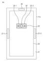
- FIG. 4 shows an external configuration example of a video communication system according to one embodiment.
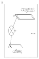
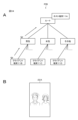
- FIG. 5 is a diagram that is referred to when describing an outline of an embodiment.
- FIG. 6 is a diagram that is referred to when describing an outline of an embodiment.
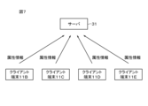
- FIG. 7 is a diagram for explaining an example of a method of generating arrangement information according to an embodiment.
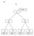
- FIG. 8 is a diagram for explaining an example of arrangement information and arrangement positions of host terminals according to an embodiment.
- FIG. 1 is a diagram that is referenced when describing issues to be considered in the present disclosure.
- Figures 2A-2D are diagrams that are referenced when discussing issues to be considered in this disclosure.
- FIG. 3 shows a configuration example of a
- FIG. 9 is a diagram for explaining another example of the arrangement positions of the host terminals.
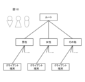
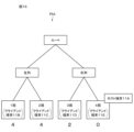
- FIG. 10 is a diagram for explaining another example of arrangement information.
- FIG. 11 is a diagram for explaining another example of arrangement information.
- FIG. 12 is a diagram for explaining another example of arrangement information.
- FIG. 13 is a diagram for explaining another example of arrangement information.
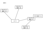
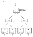
- FIG. 14 is a diagram for explaining an example of arrangement information having another structure.
- FIG. 15 is a diagram for explaining an example of arrangement information having another structure.
- FIG. 16 is a diagram for explaining distance data according to one embodiment.
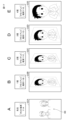
- 17A to 17E are diagrams for explaining an example in which the display form of an image is changed according to distance data.
- FIG. 18 is a diagram for explaining the changed placement positions of the host terminals in the placement information.
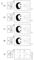
- FIGS. 19A to 19E are diagrams for explaining an example in which the display form of an image is changed according to distance data.
- FIG. 20 is a diagram for explaining a dialogue target scope according to one embodiment.
- FIG. 21 is a diagram for explaining a dialogue target scope according to one embodiment.
- FIG. 22 is a diagram for explaining another example of the dialogue target scope.
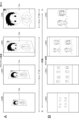
- 23A and 23B are diagrams for explaining an example of change in output form based on bidirectional intensity.
- 24A to 24C are diagrams for explaining specific examples of changes in output mode based on bidirectional intensity.
- 25A to 25C are diagrams for explaining specific examples of changes in output mode based on bidirectional intensity.
- 26A to 26C are diagrams for explaining specific examples of changes in the output form based on the bidirectional intensity.
- FIGS. 27A to 27C are diagrams for explaining specific examples of changes in output mode based on bidirectional intensity.
- FIG. 28 is a diagram for explaining a specific example of change in output mode based on interactivity strength.
- 29A to 29E are diagrams for explaining specific examples of changes in the sound output form based on the bidirectional intensity.
- 30A to 30E are diagrams for explaining specific examples of changes in sound output form based on bidirectional intensity.
- 31A to 31C are diagrams for explaining specific examples of changes in the output mode based on the bidirectional intensity.
- 32A to 32C are diagrams for explaining specific examples of changes in the output form based on the bidirectional intensity.
- 33A to 33C are diagrams for explaining specific examples of changes in the output form based on the bidirectional intensity.
- FIG. 34A and 34B are diagrams for explaining an example of processing related to a response request from a client terminal to a host terminal.
- 35A and 35B are diagrams for explaining another example of processing related to a response request from the client terminal to the host terminal.
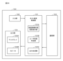
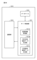
- FIG. 36 is a block diagram illustrating a configuration example of a host terminal;
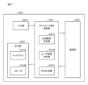
- FIG. 37 is a block diagram illustrating a configuration example of a client terminal;
- FIG. 38 is a block diagram illustrating a configuration example of a server;
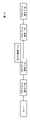
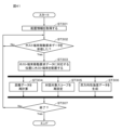
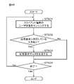
- FIG. 39 is a flow chart showing the flow of processing for generating arrangement information according to one embodiment.
- FIG. 40 is a flow chart showing the flow of processing performed on the host terminal side in the host terminal arrangement position change processing according to one embodiment.
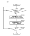
- FIG. 41 is a flowchart showing the flow of processing performed on the server side in the host terminal arrangement position change processing according to one embodiment.
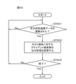
- FIG. 42 is a flow chart showing the flow of processing performed on the host terminal side in the host terminal arrangement position change processing according to one embodiment.
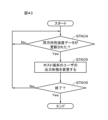
- FIG. 43 is a flow chart showing the flow of processing performed on the client terminal side in the host terminal arrangement position change processing according to the embodiment.
- FIG. 44 is a flowchart showing the flow of processing (processing on the host terminal side) considering the presence or absence of an arrangement information change instruction.
- FIG. 45 is a flow chart showing the flow of processing (processing on the server side) considering the presence or absence of an arrangement information change instruction.
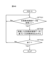
- FIG. 46 is a flowchart showing the flow of processing performed on the client terminal side in response request processing according to one embodiment.
- FIG. 47 is a flowchart showing the flow of processing performed on the server side in response request processing according to one embodiment.
- FIG. 48 is a flow chart showing the flow of processing performed on the host terminal side in response request processing according to one embodiment.
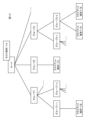
- FIG. 49 is a diagram for explaining a modification.
- FIG. 1 is a diagram schematically showing such a remote teaching system (remote teaching system 1).
- the distance learning system 1 has, for example, a host terminal 2 and four client terminals 3A to 3D. Each terminal is installed at a different location (remote location) and is connected via a network such as the Internet. Audio and video can be transmitted and received between the host terminal 2 and the client terminals 3A to 3D.
- the host terminal 2 is, for example, a teacher's terminal, and the client terminals 3A-3D are student's terminals.
- Students respond to the teacher's utterances. As shown in FIG. 2B, for example, the student at the client terminal 3A replies "I made it!. Also, the student at the client terminal 3B replies "I don't know!. Also, the student at the client terminal 3C replies, "Are you sure?" Also, the student at the client terminal 3D replies, "I am hungry.”
- Voice data corresponding to each student's reply is transmitted to the host terminal 2 via the network. For example, the voice data of the student on the client terminal 3A (speech data saying "I can do it!) may Suppose it is reproduced clearly.
- the audio data reproduced by each of the client terminals 3A to 3D is the teacher's response to the student of the client terminal 3A. Therefore, although the student at the client terminal 3A does not feel uncomfortable with the teacher's response, the students at the client terminals 3B to 3D who receive a response that does not match their own remarks will have their remarks ignored by the teacher. I feel.
- FIG. 3 shows a configuration example of a video communication system according to an embodiment of the present disclosure.
- the video communication system 10 is configured by connecting a telecommunication device 11a and a telecommunication device 11b as two information processing devices via a network 12 such as the Internet.
- the telecommunication equipment 11a and the telecommunication equipment 11b are provided in different spaces, such as different buildings or different rooms.
- a user near the telecommunication device 11a and a user near the telecommunication device 11b shown in FIG. 3 are remote users from each other.
- each of the telecommunication devices 11a and 11b basically have the same configuration.
- each of the telecommunication devices 11a and 11b includes a large-sized display, a camera for photographing the surroundings, and a microphone for collecting surrounding sounds such as environmental sounds. , a speaker for outputting sound, and the like are provided.
- the telecommunication device 11a displays images captured by the telecommunication device 11b and outputs sounds collected by the telecommunication device 11b.
- the image captured by the telecommunication device 11b shows the space in which the telecommunication device 11b is installed, including the appearance of the user of the telecommunication device 11b.
- the sound collected by the telecommunication device 11b includes environmental sounds of the space in which the telecommunication device 11b is installed, including the voice of the user of the telecommunication device 11b.
- the telecommunication device 11b displays images captured by the telecommunication device 11a and outputs sounds collected by the telecommunication device 11a.
- the image captured by the telecommunication device 11a shows the space in which the telecommunication device 11a is installed, including the appearance of the user of the telecommunication device 11a.
- the sound collected by the telecommunication device 11a includes environmental sounds of the space in which the telecommunication device 11a is installed, including the voice of the user of the telecommunication device 11a.
- the user of the telecommunication device 11b can feel as if the user of the telecommunication device 11a is on the other side of the telecommunication device 11b near him.
- the user of the telecommunication device 11a can communicate naturally with the user of the telecommunication device 11b as if the user of the telecommunication device 11b were in an adjacent space.
- the user of the telecommunication device 11b can naturally communicate with the user of the telecommunication device 11a as if the user of the telecommunication device 11a were in an adjacent space.
- the users of the telecommunication devices 11a and 11b are able to communicate more smoothly while feeling close to each other's existence, without actively trying to communicate with each other.
- the telecommunication devices 11a and 11b will be collectively referred to as the telecommunication devices 11 when there is no need to distinguish between them.
- Other configurations provided in pairs will also be collectively described in the same manner.
- two telecommunication devices are shown in FIG. 3, three or more telecommunication devices may be connected to each other.
- one telecommunication device among a plurality of telecommunication devices is set as a host terminal, and the telecommunication devices other than the host terminal are set as client terminals.
- FIG. 4 is a front view showing an example configuration of the appearance of the telecommunication device 11a.
- a vertically long rectangular display composed of an LCD (Liquid Crystal Display), an organic EL (Electro Luminescence) display, or the like is provided with a narrow frame 21 left. 22 are provided.
- LCD Liquid Crystal Display
- organic EL Electro Luminescence
- a sensor unit 23 is provided in front of the display 22 via a pointing member (not shown) fixed to the frame 21, for example.
- the sensor unit 23 is provided with a camera 24 and two sensors 25-1 and 25-2.
- a microphone 26 is provided on the upper edge portion of the upper, lower, left, and right edge portions that constitute the frame 21, and speakers 27-1 and 27-2 are provided on the left and right edge portions, respectively.
- the display 22 displays an image corresponding to the captured image captured by the telecommunication device 11b based on the image information transmitted from the telecommunication device 11b.
- the camera 24 photographs the space in front of the telecommunication device 11a.
- Video information representing a video corresponding to the captured image captured by the camera 24 is transmitted to the telecommunication device 11b.
- the sensors 25-1 and 25-2 are sensors that detect the state of the user of the telecommunication device 11a.
- a biosensor a line-of-sight detection sensor, a sensor for detecting an operation on a physical operation device such as a mouse, or the like can be applied.
- the microphone 26 collects the sound of the space in which the telecommunication device 11a is installed. Sound information representing the sound collected by the microphone 26 is transmitted to the telecommunication device 11b.
- the speakers 27-1 and 27-2 output the sound of the space in which the telecommunication device 11b is installed based on the sound information transmitted from the telecommunication device 11b.
- telecommunication devices other than the telecommunication device 11a such as the telecommunication device 11b, have the same configuration as the telecommunication device 11a shown in FIG.
- the installation positions of the camera 24, the sensors 25-1 and 25-2, the microphone 26, and the speakers 27-1 and 27-2 are only examples, and other positions are possible as long as the functions can be realized. , and the number of installations is arbitrary. Note that the display 22 and the speakers 27-1 and 27-2 correspond to the output section in this embodiment.
- each telecommunication device has the same configuration and functions as the telecommunication device 11a described above.
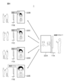
- one of the five telecommunication devices is the host terminal 11A (specifically, the terminal of the teacher who is the user), and the other telecommunication devices are client terminals 11B to 11E (specifically, Specifically, the user is a student's terminal).
- images of two students are displayed on the display (display 22A) of the host terminal 11A.
- Two students are assumed to be users of the client terminal 11E.
- the display 22B of the client terminal 11B the display 22C of the client terminal 11C, the display 22D of the client terminal 11D, and the display 22E of the client terminal 11E
- the video of the teacher who is the user of the host terminal 11A is displayed in a similar output form (this In the example, the image is displayed in a straight-facing image).
- arrangement information is defined that indicates the relationship between a plurality of information processing terminals, that is, between the host terminal and the client terminal. Then, it acquires the interactivity intensity data based on the arrangement information, and performs control to change the output form of the output unit that reproduces the video and audio based on the interactivity intensity data.
- control may be performed by a host terminal or a client terminal, or may be performed by an information processing terminal (for example, a server) that does not directly participate in a distance learning system, etc.
- the information processing apparatus of the present disclosure may be a host terminal, a client terminal, or a server.
- the communication targets of the teacher who is the user of the host terminal 11A are two students who are the users of the client terminal 11E.
- the teacher's image is specifically displayed on the display 22E, in other words, in a form that allows the students to recognize that the teacher is trying to communicate with them.
- the teacher facing the teacher is displayed on the display 22E.
- the users of the other client terminals are not the students with whom the teacher is trying to communicate. Therefore, on the displays 22B to 22D of the client terminals 11B to 11D, the images of the teacher are displayed abstractly, in other words, in such a form that the teachers can recognize that they are not trying to communicate with them. . For example, it is displayed so that the teacher is not facing the teacher and is small.
- the students who are the users of the client terminal 11E can recognize that the teacher's remarks are directed at them. Further, the students who are users of the client terminals 11B to 11D can recognize that the teacher's remarks are not directed at them. Therefore, only the student who is the user of the client terminal 11E can respond to the teacher's statement. As described above, smooth communication can be achieved without the above-described problems.
- the arrangement information is information indicating the relationship between information processing terminals, specifically, between a host terminal and a plurality of client terminals.
- Placement information is generated, for example, based on attribute information.
- the arrangement information is generated by a server, for example.
- each of the client terminals 11B to 11E transmits attribute information of the user of the client terminal to the server 31 using the communication function.
- the server 31 generates arrangement information using the attribute information transmitted from each client terminal.
- the position and group number in the virtual classroom are sent to the server 31 as attribute information.
- the client terminal 11B transmits to the server 31 the attribute information "left column/group 1".
- the client terminal 11C transmits to the server 31 the attribute information "left column/group 2”.
- Attribute information of "right column/3rd group” is transmitted to the server 31 from the client terminal 11D.
- the attribute information "right column/group 4" is transmitted to the server 31 from the client terminal 11E.
- the server 31 generates location information based on the attribute information sent from each client terminal.
- FIG. 8 shows an example of placement information (placement information PIA) generated by the server 31 .
- the placement information PIA has, for example, a hierarchical structure (tree structure). That is, the placement information PIA has a "root” as a starting point, and has "left column” and "right column” as layers next to the root. Furthermore, the arrangement information PIA has the arrangement position in the arrangement information PIA of each team, in other words, the client terminal as the next hierarchy.
- the placement information PIA has "group 1 (corresponding to the attribute information of the client terminal 11B)” and “group 2 (corresponding to the attribute information of the client terminal 11C)” as the hierarchy next to the "left column”.
- the arrangement information PIA has "group 3 (corresponding to the attribute information of the client terminal 11D)” and “group 4 (corresponding to the attribute information of the client terminal 11E)” as the hierarchy next to the "right column”. Attributes in the arrangement information and attributes corresponding to each client terminal (team name in this example) are also referred to as nodes as appropriate in the following description.
- the host terminal 11A is arranged in the arrangement information.
- the host terminal 11A (the user is the teacher's terminal) is arranged at a position corresponding to the route in the arrangement information PIA by default.
- the location of the host terminal 11A in the location information PIA is not limited to the route.
- the host terminal 11A may be arranged in a node designated in advance by the host terminal 11A.
- the host terminal 11A may be arranged in the node "right column".
- the arrangement position of the host terminal 11A in the arrangement information PIA is changed. For example, the arrangement position of the host terminal 11A is changed (moved) from the root to the node "right column” or the node "left column", or from the node "right column” to the node "left column”.
- the client terminal sends attribute information to the server, but it is not limited to this.
- location information may be generated based on attribute information input by the host terminal. Specifically, even if the host terminal instructs the server about nodes such as groups and right columns, which are examples of attribute information, and client terminals belonging to the nodes, the server generates arrangement information according to the instructions. good.
- FIG. 10 shows another example of arrangement information.
- the example shown in FIG. 10 uses gender (male/female/other) as attribute information, and shows arrangement information generated according to gender.
- FIG. 11 shows another example of arrangement information.
- the example shown in FIG. 11 uses the place of residence (country name/city) as the attribute information and shows the location information generated according to the place of residence.
- FIG. 12 shows another example of arrangement information.
- the example shown in FIG. 12 shows arrangement information generated according to seat positions, using seat positions in event tickets for live performances, movies, and the like as attribute information.
- the seat position in this example is, for example, a virtual seat position, and a movie screen or a live artist viewed from the virtual seat position is displayed on the display of the client terminal.
- the seat positions associated with the ticket are transmitted to the server, and the server arranges the seats shown in FIG. 12 based on the seat positions.
- Information can be generated. That is, it is possible to simplify the input of attribute information on the client terminal.
- attribute information is not always required to generate location information.
- each client terminal is classified into an arbitrary group having no attribute, as shown in FIG. 13, for example.
- the classification may be performed randomly or according to preset rules.
- the structure of the arrangement information may be a structure other than the tree structure.
- the arrangement information may be a linear list structure.
- the arrangement information may have a graph structure. 14 and 15, the host terminal 11A and the client terminal 11C are shown so as to overlap each other, but this means that the arrangement position of the host terminal 11A and the arrangement position of the client terminal 11C are the same. showing.
- the interactivity intensity data is data corresponding to the interactivity intensity based on the arrangement information described above.
- the interactivity strength data includes distance data indicating the distance between predetermined information processing terminals in the above-described arrangement information.
- the interactivity strength data in this example includes distance data indicating the distance between the above-described host terminal and each client terminal.
- FIG. 16 shows the arrangement information PIA described above.
- the arrangement position of the host terminal 11A is, for example, the same arrangement position as the arrangement position of Team 4 (client terminal 11E).
- the distance data is defined, for example, by the number of movements to the arrangement position of the host terminal 11A along the nodes in the arrangement information PIA. Since the arrangement position of the host terminal 11A and the arrangement position of the client terminal 11E are the same, the distance data indicating the distance from the client terminal 11E to the host terminal 11A is "0". In addition, the host terminal 11A seen from the client terminal 11D reaches the position of the host terminal 11A through the node "right column”. Also, the host terminal 11A viewed from the client terminal 11C reaches the position of the host terminal 11A through the node "left column", the route, and the node "right column”. 4”. The same applies to distance data from the client terminal 11B to the host terminal 11A.
- control is performed to change the output form of the output unit according to the distance data, which is one of the bidirectional intensity data.
- FIG. 17A shows an example of an image displayed on the display 22A of the teacher's terminal, that is, the host terminal 11A. All or some of the students who are users of the client terminals 11B to 11E are displayed on the display 22A. 17B to 17E show examples of images displayed on the displays 22B to 22E of the client terminals 11B to 11E. Teachers are displayed on the displays 22B to 22E.
- the teacher who is the user of the host terminal 11A will be referred to as the teacher TH
- the students of the respective users of the client terminals 11B to 11E will be referred to as the students SB to SE (however, even if there are a plurality of students, they are not distinguished). Appropriately called.
- the larger the distance data the more abstractly the information corresponding to the host terminal 11A and the client terminals 11B to 11E (in this example, the teacher TH and the images of the students SB to SE). is changed. Also, the smaller the distance data, the more the output form is changed so that the information corresponding to the host terminal 11A and the client terminals 11B to 11E is expressed more concretely.
- the distance data between the host terminal 11A and the client terminal 11E is "0". That is, when viewed from the host terminal 11A, the distance data of the client terminal 11E is the smallest among the client terminals 11B to 11E. Therefore, the image of the student SE who is the user of the client terminal 11E is specifically displayed on the display 22A of the host terminal 11A. For example, the display 22A displays only the student SE (see FIG. 17A). Conversely, when viewed from the client terminal 11E, the distance data for the host terminal 11A is also the smallest. Accordingly, the appearance of the teacher TH is specifically displayed on the display 22E of the client terminal 11E. For example, on the display 22E, the figure of the teacher TH is displayed in a large size facing the teacher TH (see FIG. 17E).
- the distance data between the host terminal 11A and the client terminal 11D is "2". Therefore, the display 22D of the client terminal 11D displays the appearance of the teacher TH more abstractly than the teacher TH displayed on the display 22E of the client terminal 11E. For example, on the display 22D, the figure of the teacher TH is displayed slightly tilted (not facing) and slightly smaller (see FIG. 17D).
- the distance data between the host terminal 11A and the client terminal 11C is "4". Therefore, the teacher TH is displayed on the display 22C of the client terminal 11C more abstractly than the teacher TH displayed on the displays 22E and 22D. For example, on the display 22C, the figure of the teacher TH is greatly tilted (not facing) and displayed in a small size (see FIG. 17C).
- the distance data between the host terminal 11A and the client terminal 11B is also "4". Therefore, the teacher TH is displayed on the display 22B of the client terminal 11B in the same display form as the display 22C (see FIG. 17B).
- the arrangement position of the host terminal 11A in the arrangement information PIA can be changed.
- FIG. 18 consider an example in which the arrangement position of the host terminal 11A is changed from the position of the client terminal 11E to the root.
- the distance data between the host terminal 11A and each client terminal changes as the arrangement of the host terminal 11A changes.
- the distance data between the host terminal 11A and each client terminal is all "2".
- the display form of the video is also changed as shown in FIGS. 19A to 19E.
- the distance data from the host terminal 11A to each client terminal is all equal to "2". Therefore, the display 22A of the host terminal 11A displays an image that looks down on all the students (students SB to SE) (see FIG. 19A).
- the students (students SB and SC) of the client terminals 11B and 11C are displayed on the left side of the display 22A, and the client terminals 11D and 11E are displayed on the right side of the display 22A. Students (students SD and SE) may be displayed.
- each client terminal displays (displays 22B to 22E) of each client terminal display the teacher TH in a similar display form (see FIGS. 19B to 19E).
- Interactivity intensity data may include interaction target scope data.
- the dialogue target scope data is data indicating whether or not it is included in a range in which interaction via the output unit is possible (hereinafter also referred to as dialogue target scope as appropriate).
- the dialogue target scope is set based on the distance data described above, for example. For example, a threshold is set for the distance data to the host terminal 11A, and the dialogue target scope is set so as to include client terminals corresponding to distance data equal to or less than the threshold.
- the dialogue target scope is set to include client terminals whose distance data is "1" or less.
- the arrangement position of the host terminal 11A is assumed to be the node "right column”.
- the respective distance data from the host terminal 11A to the client terminals 11B to 11E are "3", "3", "1", "1". Therefore, in this example, the client terminals 11D and 11E are client terminals included in the dialogue target scope (the dialogue target scope SP indicated by the dotted line in FIG. 20).
- the client terminals 11B and 11C are client terminals that are not included in the dialogue target scope SP.
- the client terminals included in the dialogue target scope SP may also be changed in accordance with the change in the arrangement position of the host terminal 11A. For example, assume that the host terminal 11A moves to the position of the client terminal 11E as shown in FIG. As the host terminal 11A moves, the distance data between the host terminal 11A and the client terminal 11E changes from “1" to "0” as shown in FIG. Also, the distance data between the host terminal 11A and the client terminal 11E changes from "1" to "2". Therefore, the client terminal included in the dialog subject scope SP is only the client terminal 11E, and the other client terminals 11B to 11D are client terminals not included in the dialog subject scope SP.
- the dialogue target scope does not necessarily have to be based on distance data.
- the dialogue target scope SP may be set so as to include all of the client terminals arranged in the hierarchy below the host terminal 11A in the arrangement information.
- control is performed to change the output form of the output unit so that the information corresponding to the client terminal is abstractly expressed.
- control is performed to change the output form of the output unit so that the information corresponding to the client terminal is specifically expressed.
- FIG. 23 shows a display example of information (eg, teacher's TH) corresponding to the host terminal displayed on the display of the client terminal.
- the rightmost diagram of the four diagrams in FIG. 23A shows the display 22E of the client terminal (for example, the client terminal 11E) included within the dialogue target scope SP.
- the display 22E is displayed in a form in which the teacher TH is facing the teacher.
- information for example, group name regarding the current communication partner of the teacher TH, that is, the client terminal within the dialogue target scope SP may be displayed.
- the appearance of the teacher TH is displayed abstractly.
- the teacher TH is displayed at an angle so that the teacher TH does not face the teacher.
- further display is made according to the distance data.
- the figure of the teacher TH is displayed to become smaller as the distance data becomes larger.
- similar display control is performed on the display 22A of the host terminal 11A.
- the output mode of the output unit is changed based on the distance data included in the interactivity intensity data and the dialogue target scope data indicating whether or not the object is within the dialogue target scope.
- FIGS. 23A and 23B schematically show the display form, for example, by performing a predetermined calculation using the distance data and the dialogue target scope data, an evaluation value corresponding to the interactivity intensity data can be obtained.
- the computation is such that the smaller the distance data and the closer the dialogue object scope data, the higher the evaluation value.
- an evaluation value corresponding to the bidirectional intensity data is obtained. The higher the evaluation value, the more concretely the images of the teacher and students are displayed, and the lower the evaluation value, the more concretely the images of the teacher and students are displayed.
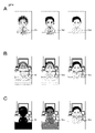
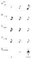
- FIG. 24A is an example in which the stronger the interactive strength, the more clearly the teacher TH is displayed, and the weaker the interactive strength, the more blurred the teacher TH.
- FIG. 24B is an example in which the stronger the interactive strength, the clearer the teacher TH's figure is displayed, and the weaker the interactive strength, the lighter the density of the teacher TH's figure is displayed.
- This example can be realized by changing the ⁇ value in image processing called so-called ⁇ blending.
- FIG. 24C the stronger the interactive strength, the more clearly the teacher TH is displayed, and the weaker the interactive strength, the closer the teacher TH's appearance is to black (it is difficult to recognize that it is the teacher TH). is displayed).
- the example shown in FIG. 25A is an example in which the stronger the interactive strength, the more color the teacher TH's appearance is displayed, and the weaker the interactive strength, the lower the gradation in the image of the teacher TH's appearance.
- the figure of the teacher TH is displayed in grayscale.
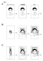
- FIG. 25B is an example in which the figure of the teacher TH is displayed larger as the interactivity strength is stronger, and the figure of the teacher TH is displayed smaller as the interactivity strength is weaker.
- the stronger the interactivity, the more the teacher TH is displayed to face the teacher, and the weaker the interactivity, the more the teacher TH faces sideways instead of facing the teacher. is an example.
- the example shown in FIG. 26A is an example in which the stronger the interactivity strength, the closer the teacher TH is displayed, and the weaker the interactivity strength, the farther the teacher TH is displayed.
- the example shown in FIG. 26B is an example in which the stronger the interactivity, the larger the displayed region of the teacher TH. In this example, when the interactive strength is the strongest, the teacher TH's entire figure is displayed, and when the interactive strength is the weakest, the teacher TH's figure is slightly displayed.
- the example shown in FIG. 26C is an example in which the stronger the interactive strength, the more clearly the teacher TH is displayed, and the weaker the interactive strength, the more blurred or partially displayed the teacher TH.
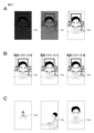
- the example shown in FIG. 27A is an example in which the stronger the interactive strength, the higher the brightness of the video including the teacher's TH, and the weaker the interactive strength, the lower the brightness of the video including the teacher's TH.
- the moving image parameters are set so that the stronger the interactive strength, the clearer the image of the teacher TH becomes, and the weaker the interactive strength, the more difficult it is to recognize the image of the teacher TH.
- Motion picture parameters include frame rate, resolution, bit rate, and the like. For example, at least one of the frame rate, resolution, and bit rate increases as the interactivity strength increases, and at least one of the frame rate, resolution, and bit rate decreases as the interactivity strength decreases.
- FIG. 27C is an example of switching the camera for photographing the figure of the teacher TH so that the stronger the interactivity intensity is, the more the entire figure of the teacher TH is captured.
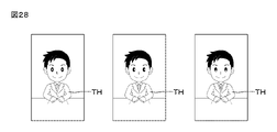
- FIG. 28 is an example of switching the line of sight of the teacher TH according to the interactivity intensity.
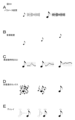
- the example shown in FIG. 29A is an example in which the higher the interactivity strength, the higher the volume of the reproduced sound, and the lower the interactivity strength, the lower the volume of the reproduced sound.
- the example shown in FIG. 29B is an example in which the stronger the bidirectional strength, the smaller the amount of echo added to the reproduced sound, and the weaker the bidirectional strength, the larger the amount of echo added to the reproduced sound.
- the example shown in FIG. 29C is an example in which the stronger the interactivity strength, the smaller the reverberation added to the reproduced sound, and the weaker the interactivity strength, the greater the reverberation added to the reproduced sound.
- 29D is an example in which the stronger the interactivity intensity, the smaller the noise added to the reproduced sound, and the weaker the interactivity intensity, the larger the noise added to the reproduced sound.
- the example shown in FIG. 29E is an example in which the sound picked up by the microphone closer to the teacher TH is reproduced as the bidirectional strength is stronger, and the sound is picked up by the microphone farther from the teacher TH as the bidirectional strength is weaker. This is an example in which the generated sound is reproduced.
- FIG. 30A shows parameters in sound reproduction processing so that the stronger the interactivity strength, the more concretely (clearly) the sound is reproduced, and the weaker the interactivity strength, the more abstract (unclear) the sound is reproduced.
- Such parameters include sampling frequency, bit rate, and the like.
- FIG. 30B is an example of changing the arrangement of sound sources according to the interactivity strength. For example, the stronger the interactivity, the more the sound is localized near the front of the user of the client terminal. is played.
- FIG. 30C is an example of changing the frequency characteristic according to the bidirectional strength.
- FIG. 30D shows an example in which only the voice of the teacher TH is reproduced when the interactivity strength is high, and a different sound source is mixed with the teacher's voice when the interactivity strength is low, thereby making it difficult to hear the teacher TH's voice.
- FIG. 30E is an example in which the delay of the reproduced sound is reduced as the interactivity strength is stronger, and the delay of the reproduced sound is increased as the interactivity strength is weaker.
- the host terminal 11A can, for example, output video and sound corresponding to any client terminal to its own output unit such as the display 22A.
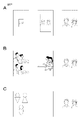
- FIG. 31A is an example in which the stronger the interactivity with the client terminal, the larger the information corresponding to the client terminal (for example, the student's video) is displayed.
- FIG. 31B is an example of switching cameras so that the stronger the interactivity, the more specifically the information corresponding to the client terminal is displayed.
- the strength of interactivity with the client terminal is strong, the image captured by the camera placed in front of the student of the client terminal is displayed, and when the strength of interactivity with the client terminal is weak, the client terminal Images taken by cameras placed beside and behind the students are displayed.
- FIG. 31C the stronger the interactivity strength, the more the image of the student corresponding to the client terminal is displayed. For example.
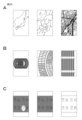
- FIG. 32A is an example of displaying more specific attributes as the strength of interactivity with the client terminal increases. For example, when the interactivity is strong, a specific map (fine map) is displayed, and when the interactivity is weak, a rough map such as a region or country is displayed.
- FIG. 32B is an example in which the attributes of the client terminal (for example, seat position) are displayed as they are.
- FIG. 32C is an example in which the user of the client terminal specified by the host terminal 11A is displayed so as to be spotlighted.
- Motion picture parameters include frame rate, resolution, bit rate, and the like. For example, at least one of the frame rate, resolution, and bit rate increases as the interactivity strength increases, and at least one of the frame rate, resolution, and bit rate decreases as the interactivity strength decreases.
- FIG. 33B is an example of changing the arrangement of the students who are the users of the client terminals.
- FIG. 33C is an example of changing the position of the virtual viewpoint in the virtual space according to the interactivity strength.
- a response request is transmitted to the host terminal 11A based on the inter-node connection of the arrangement information. Specifically, a response request is transmitted from the client terminal 11B to the host terminal 11A located on the route via the node "male".
- the host terminal 11A receives the response request from the client terminal 11B. By transmitting the response request based on the location information, the host terminal 11A can recognize that the response request has been made from the client terminal whose attribute is "male". Therefore, for example, as shown in FIG. 34B, an image is displayed on the display 22A of the host terminal 11A in which the part of the man is blinking.
- the host terminal 11A is placed at the node "Others", and the client terminals (in this example, the client terminals 11D and 11E) located one layer below the node are the object of interaction.
- the display 22A of the host terminal 11A displays the users (students SD, SE) corresponding to the client terminals within the dialogue target scope SP.
- the client terminal 11B issues a response request to the host terminal 11A.
- the response request is transmitted to the host terminal 11A located at the node "Others" via the nodes "Male” and "Root".
- the response request made by the client terminal 11B is a response request from outside the dialogue target scope SP.
- the presence of the response request is displayed in such a way that it is easy to recognize that the response request is from outside the dialogue target scope SP.
- FIG. 35B by blinking the vicinity of the corner of the display 22A, the user of the host terminal 11A is notified that there is a response request from outside the dialogue target scope SP.
- FIG. 36 is a block diagram showing a configuration example of the host terminal 100.
- the host terminal 100 has a host terminal control section 101, an input section 102, a communication section 103, and an output section 104, for example.
- the host terminal control unit 101 comprehensively controls the operation of the host terminal 100 .
- the host terminal control unit 101 is composed of, for example, a CPU (Central Processing Unit), and has a ROM (Read Only Memory) in which programs are stored and a RAM (Random Access Memory) used as a work memory. (The illustration of these memories is omitted.)
- the host terminal control unit 101 outputs the interactivity intensity data based on the arrangement information indicating the relationship between the plurality of client terminals 200 including itself. Control is performed to change the output form of the unit 104 .
- the host terminal control unit 101 has an arrangement information state change instruction unit 101A, a user state determination unit 101B, and an output generation unit 101C.
- the arrangement information state change instruction unit 101A generates arrangement information state change instruction data for changing arrangement information.
- the arrangement information state change instruction data may include data for instructing a change in the arrangement position of the host terminal in the arrangement information (hereinafter referred to as host terminal movement request data), or may change the arrangement information itself (reset data). ) (hereinafter referred to as location information change instruction data), or both.
- the user state determination unit 101B interprets the user's intention based on the input result to the input unit 102.
- the output generation unit 101C changes the output form of information in the output unit 104 based on the bidirectional intensity data.
- the bidirectional intensity data and the output form are associated with each other. Determined by referring to the table.
- Interactivity intensity data may include data indicating how to change the output configuration.
- the input unit 102 includes a device that receives user's operation input, a sensor that senses the user's state, and the like.
- a keyboard, a touch panel, or the like is given as an example of a device that receives a user's operation input.
- sensors include a microphone that accepts voice input and a camera that accepts gesture input.
- the communication unit 103 communicates with other information processing terminals, specifically, client terminals 200 and servers 300, which will be described later.
- the communication unit 103 has a modulation/demodulation circuit and the like (not shown) corresponding to the communication system.
- the output unit 104 is a device that outputs information from other information processing terminals (for example, person images of students and live audience members).
- the output unit 104 according to this embodiment has a display 104A (for example, corresponding to the display 22A described above) and a speaker 104B (for example, corresponding to the speakers 27-1 and 27-2 described above).
- FIG. 37 is a block diagram showing a configuration example of the client terminal 200.
- the client terminal 200 has a client terminal control section 201, an input section 202, a communication section 203, and an output section 204, for example.
- the client terminal control unit 201 comprehensively controls the operation of the client terminal 200.
- the client terminal control unit 201 is composed of, for example, a CPU, and has a ROM in which programs are stored and a RAM used as a work memory (not shown). )
- the client terminal control unit 201 performs control to change the output form of the output unit 204 according to the interactivity intensity data based on the arrangement information indicating the relationship between the host terminal 100 including itself and the plurality of client terminals 200. .
- the client terminal control section 201 has a response request generation section 201A, a user state determination section 201B, and an output generation section 201C.
- the response request generation unit 201A generates response request data for requesting a response to the host terminal 100.
- FIG. The user state determination unit 201B interprets the user's intention based on the input result to the input unit 202.
- FIG. The output generation unit 201C changes the output form of information in the output unit 204 based on the bidirectional intensity data.
- the bidirectional intensity data and the output form are associated with each other. Determined by referring to the table.
- Interactivity intensity data may include data indicating how to change the output configuration.
- the input unit 202 includes a device that accepts user's operation input, a sensor that senses the user's state, and the like.
- a keyboard, a touch panel, or the like is given as an example of a device that receives a user's operation input.
- sensors include a microphone that accepts voice input and a camera that accepts gesture input.
- the communication unit 203 communicates with other information processing terminals, specifically the host terminal 100 and the server 300 .
- the communication unit 203 has a modulation/demodulation circuit and the like (not shown) corresponding to the communication system.
- the output unit 204 is a device that outputs information from other information processing terminals (for example, person images of students and live audience members).
- the output unit 204 according to this embodiment has a display 204A and a speaker 204B.
- FIG. 38 is a block diagram showing a configuration example of the server 300.
- the server 300 has a server control unit 301, a database 302, and a communication unit 303, for example.
- the server control unit 301 comprehensively controls the operation of the server 300 .
- the server control unit 301 is composed of, for example, a CPU, and has a ROM in which programs are stored and a RAM used as a work memory (not shown).
- the server control unit 301 has an arrangement information management unit 301A, an interactivity strength data generation unit 301B, and a response request expression data generation unit 301C.
- the placement information management unit 301A manages the placement information, specifically, the generation and modification of the placement information, the placement position of the host terminal 100 in the placement information, and the like.
- the interactivity strength data generation unit 301B acquires the distance data and the dialogue target scope data in the arrangement information, and generates the interactivity strength data based on the distance data and the dialogue target scope data.
- the response request expression data generation unit 301C generates response request expression data defining how to output a response request from the client terminal 200 to the host terminal 100.
- the database 302 is a database that stores the processing results of the arrangement information management unit 301A, the attributes of each client terminal 200, and the like.
- the communication unit 303 communicates with the host terminal 100 and the client terminal 200.
- the communication unit 303 has a modulation/demodulation circuit and the like according to the communication system.
- each of the plurality of client terminals 200 transmits attribute information to the server 300 via the communication section 203 .
- the attribute information is acquired by the server 300 receiving the attribute information transmitted from each client terminal 200 via the communication unit 303 .
- the attribute information received by the communication unit 303 is supplied to the server control unit 301 . Then, the process proceeds to step ST102.
- step ST102 the arrangement information management section 301A of the server control section 301 generates arrangement information using the attribute information. Then, the process proceeds to step ST103.
- step ST103 the arrangement information management section 301A determines the arrangement position of the host terminal 100 in the generated arrangement information.
- the placement information management unit 301A places the host terminal 100 on the route in the generated placement information.
- the host terminal 100 may be arranged at a position other than the route, such as the arrangement position designated by the host terminal 100 . Then, the process proceeds to step ST104.
- step ST104 the location information management unit 301A calculates distance data between the host terminal 100 and each client terminal 200 based on the generated location information. Also, the placement information management unit 301A sets the dialogue target scope based on the generated placement information. The criteria for setting the dialogue target scope may be determined in advance or may be instructed by the host terminal 100 . Then, the process proceeds to step ST105.
- the interactivity strength data generator 301B generates the interactivity strength data for each client and the host terminal 100 based on the distance data and the dialogue target scope data indicating whether or not it is within the dialogue target scope.
- Interactivity intensity data for each client terminal 200 viewed from the perspective is generated.
- Interactivity intensity data is transmitted to host terminal 100 and client terminal 200 .
- the output form of the output section 104 is changed based on the interactivity intensity data transmitted from the server 300 .
- Such processing is performed by the host terminal control unit 101 (specifically, the output generation unit 101C).
- the output form in the output section 204 is changed based on the interactivity intensity data transmitted from the server 300 .
- Such processing is performed by the control unit 201 (specifically, the output generation unit 201C).
- the server 300 receives the ID of the client terminal 200, and reads attribute information corresponding to the ID from the database 302. You may do so. Moreover, as described above, when the arrangement information management unit 301A generates the arrangement information, the attribute information may not be used. Also, the generated arrangement information may be transmitted from the server 300 to the host terminal 100 or the client terminal 200 . Since the host terminal 100 can change the arrangement position in the arrangement information, it is preferable that the arrangement information be transmitted to at least the host terminal 100 . The arrangement information may be displayed on the host terminal 100 so that the user of the host terminal 100 can recognize it.
- FIG. 40 is a flow chart showing the flow of processing performed by the host terminal 100 in the host terminal arrangement position change processing.
- input section 102 senses the user state of host terminal 100 .
- a sensing result by the input unit 102 is supplied to the host terminal control unit 101 . Then, the process proceeds to step ST202.
- step ST202 the user state determination section 101B interprets the sensing result from the input section 102. Then, user state determination section 101B determines whether or not there is an input corresponding to the movement request of host terminal 100 .
- the arrangement information PIA see FIG. 9
- the user state determination unit 101B interprets the contents of speech and operation of the user of the host terminal 100, and interprets that the user of the host terminal 100 desires to move to the position of "group 4" in the arrangement information. That is, user state determination section 101B determines that there is an input corresponding to a movement request. In this case, the process proceeds to step ST203.
- the process proceeds to step ST204.
- step ST203 the arrangement information state change instruction unit 101A generates arrangement state change instruction data, more specifically, host migration request data.
- the generated host migration request data is transmitted to the server 300 via the communication section 103 . Then, the process proceeds to step ST204.
- step ST204 the host terminal control section 101 determines whether or not a series of processes has ended. If not completed, the process returns to step ST201, and if completed, the process in the host terminal 100 ends.
- FIG. 41 is a flow chart showing the flow of processing performed on the server 300 side subsequent to the processing described in FIG. 40 in the host terminal arrangement position change processing.
- the server control section 301 acquires arrangement information. For example, already generated arrangement information is read from the database 302 . Then, the process proceeds to step ST302.
- step ST302 server control section 301 monitors whether host terminal movement request data from host terminal 100 is received via communication section 303 or not. If server control section 301 determines that it has not received the host terminal movement request data, it repeats the process of step ST302. If server control section 301 determines that host terminal movement request data has been received, the process proceeds to step ST303.
- step ST303 the location information management section 301A locates the host terminal 100 at the position corresponding to the host terminal movement request data in the location information.
- step ST303 the processes of steps ST304 to ST306 are performed. Since the arrangement position of host terminal 100 in the arrangement information has been changed, distance data is recalculated (step ST304). Also, since the placement position of the host terminal 100 in the placement information is changed, the dialog target scope is reset and the dialog target scope data is updated (step ST305). Interactivity strength data is generated again based on the recalculated distance data and the updated interaction target scope data (step ST306). The generated interactivity intensity data is transmitted to each of the host terminal 100 and the client terminal 200 via the communication section 303 . Then, the process proceeds to step ST307.
- step ST307 the server control unit 301 determines whether or not the series of processes has ended. If not completed, the process returns to step ST302, and if completed, the process in server 300 ends.
- FIG. 42 is a flow chart showing the flow of processing performed by the host terminal 100 subsequent to the processing described in FIG. 41 in the host terminal arrangement position change processing.
- the host terminal control section 101 determines whether or not the interactivity strength data has been updated. Such determination can be made based on whether or not new bidirectional intensity data has been received via the communication unit 103 . If the bidirectional intensity data has not been updated, the process returns to step ST401. If the bidirectional intensity data has been updated, the process proceeds to step ST402.
- step ST402 the output generation section 101C changes the output form of the client terminals 200 to the host terminal 100 based on the updated interactivity intensity data. For example, assume that when the host terminal 100 is located at the root, images of all the students who are users of the client terminal 200 are displayed on the display 104A. It is assumed that the host terminal 100 has moved to the position of the client terminal 200 corresponding to "group 4" according to the host terminal movement data. In this case, the interactivity strength data is updated so as to increase the interactivity strength between the host terminal 100 and the client terminals 200 of the "group 4". Based on the updated interactivity intensity data, display 104A now displays only the students of "Group 4". Then, the process proceeds to step ST403.
- step ST403 the host terminal control section 101 determines whether or not a series of processes has ended. If not completed, the process returns to step ST401, and if completed, the process in the host terminal 100 ends.
- FIG. 43 is a flow chart showing the flow of processing performed by the client terminal 200 subsequent to the processing described in FIG. 41 in the host terminal arrangement position change processing.
- the client terminal control section 201 determines whether or not the interactivity strength data has been updated. Such determination can be made according to whether or not new bidirectional intensity data has been received via the communication unit 203 . If the bidirectional intensity data has not been updated, the process returns to step ST404. If the bidirectional intensity data has been updated, the process proceeds to step ST405.
- step ST405 the output generating section 201C changes the output mode for the user of the host terminal 100 in the output section 104 based on the updated interactivity intensity data.
- the interactivity strength data before and after the update is compared, and if the interactivity strength becomes stronger, the user of the host terminal 100 is output more specifically in the output unit 204, and if the interactivity strength becomes weaker. , the user of the host terminal 100 in the output unit 204 is more abstractly output. Then, the process proceeds to step ST406.
- step ST406 the host terminal control section 101 determines whether or not a series of processes has ended. If not completed, the process returns to step ST404, and if completed, the process in each client terminal 200 ends.
- the arrangement information state change instruction data may include arrangement information change instruction data as well as host terminal movement request data.
- An instruction to change the arrangement information is issued by the host terminal 100, for example.
- FIG. 44 is a flow chart showing the flow of processing (processing performed by the host terminal 100) in consideration of whether there is an instruction to change the arrangement information.
- the same reference numerals are given to the same processes as those described above, and overlapping explanations are appropriately omitted. The same applies to descriptions of other flowcharts.
- step ST205 the user state determination section 101B interprets the sensing result from the input section 102.
- step ST. the user state determination unit 101B determines whether or not there is an input corresponding to the arrangement information change instruction. For example, the user of the host terminal 100 performs an utterance or an input operation saying, "Let's split up by residence instead of groups.” Such speech or the like is detected by the input unit 102 .
- the user state determination unit 101B interprets the content of speech and the content of the operation of the user of the host terminal 100, and interprets that the user of the host terminal 100 has instructed to change the arrangement information.
- the user state determination unit 101B determines that there is an input corresponding to an instruction to change the arrangement information. In this case, the process proceeds to step ST206.
- the process proceeds to step ST204.
- step ST206 the arrangement information state change instruction section 101A generates arrangement state change instruction data, more specifically, arrangement information change instruction data.
- the generated arrangement information change instruction data is transmitted to server 300 via communication unit 103 . Then, the process proceeds to step ST204.
- FIG. 45 is a flow chart showing the flow of processing (processing performed by the server 300) in consideration of whether or not there is an instruction to change the arrangement information.
- server control section 301 determines whether or not arrangement information state change instruction data has been received. When server control section 301 determines that it has not received the arrangement information state change instruction data, the process returns to step ST308. If server control section 301 determines that it has received arrangement information state change instruction data, the process proceeds to step ST309.
- step ST309 the server control section 301 determines whether or not the received arrangement information state change instruction data includes arrangement information change instruction data. If the arrangement information change instruction data is not included, the process proceeds to step ST311. If the arrangement information change instruction data is included, the process proceeds to step ST310.
- the arrangement information management section 301A generates new arrangement information based on the arrangement information change instruction data.
- the placement information management unit 301A generates the placement information according to, for example, the attribute information included in the placement information change instruction data. Then, the process proceeds to step ST311.
- step ST311 the server control section 301 determines whether or not the received arrangement information state change instruction data includes host terminal movement request data. If the host terminal move request data is not included, the process proceeds to steps ST304 to ST306. If host terminal movement request data is included, the process proceeds to step ST303.
- step ST311 If the host terminal movement request data is included in the determination process of step ST311, in the process of step ST303, the host terminal is moved to the position designated by the host terminal movement request data in the arrangement information generated in step ST310. 100 are placed.
- response request processing Processing related to response requests from client terminals
- FIG. 46 is a flow chart showing the flow of processing performed by the client terminal 200 in response request processing.
- the input section 202 senses the user state of the client terminal 200.
- FIG. The sensing result by input section 202 is sent to client terminal control section 201, and the process proceeds to step ST502.
- step ST502 the user state determination section 201B interprets the sensing result from the input section 502. User state determination section 201B then determines whether or not there is an input corresponding to the response request from client terminal 200 . For example, when an utterance such as "Teacher, I have a question.” In this case, the process proceeds to step ST503. If user state determination section 201B determines that there is no input corresponding to the response request, the process proceeds to step ST504.
- step ST503 the response request generating section 201A generates response request data.
- the generated response request data is transmitted to server 300 via communication unit 203 . Then, the process proceeds to step ST504.
- step ST504 the client terminal control section 201 determines whether or not a series of processes has ended. If not completed, the process returns to step ST502, and if completed, the process in the client terminal 200 ends.
- FIG. 47 is a flowchart showing the flow of processing performed on the server 300 side subsequent to the processing described in FIG. 46 in response request processing.
- server control section 301 monitors whether or not response request data from client terminal 200 is received. If server control section 301 determines that it has not received the response request data, it repeats the process of step ST601. When server control section 301 determines that response request data has been received, the process proceeds to step ST602.
- server control section 301 (specifically, response request expression data generation section 301C) refers to the arrangement information to determine whether client terminal 200 that has transmitted the response request data is within the dialogue target scope. to judge whether Then, the process proceeds to step ST603.
- the response request expression data generating section 301C generates response request expression data.
- the response request expression data generation unit 301C makes it easier for the user of the host terminal 100 to recognize the response request (for example, The response request expression data is generated so as to be displayed in the mode shown in FIG. 34B).
- the response request expression data generation unit 301C generates a remote response request (for example, when the response request is sent from outside the display 104A).
- the response request expression data is generated so as to be displayed or the like in the manner in which the request is made (for example, the manner shown in FIG. 35B).
- the generated response request expression data is transmitted to the host terminal 100 via the communication section 303 . Then, the process proceeds to step ST604.
- step ST604 the server control unit 301 determines whether or not the series of processes has ended. If it has not ended, the process returns to step ST601, and if it has ended, the process in server 300 ends.
- FIG. 48 is a flow chart showing the flow of processing performed by the host terminal 100 subsequent to the processing described in FIG. 47 in response request processing.
- step ST 701 host terminal control section 101 determines whether or not response request expression data has been received via communication section 103 .
- the processing relating to step ST701 is repeated.
- step ST702 the process proceeds to step ST702.
- step ST702 the output generating section 101C outputs the response request by display or sound reproduction in a manner based on the response request expression data. Then, the process proceeds to step ST703.
- step ST703 the server control unit 301 determines whether or not the series of processes has ended. If it has not ended, the process returns to step ST701, and if it has ended, the process in server 300 ends.
- Restrictions may be set on the nodes (arrangement possible range) where the host terminal can be arranged in the arrangement information.
- the distance data between the host terminal and the client terminal can be set to a certain value or more. Since the distance data can be set to a certain value or more, the user's display of the client terminal can be abstracted to a certain degree or more. For example, it is possible to make the face of the user of the client terminal unclear beyond a certain level. Therefore, it is possible to protect the privacy of the user of the client terminal.
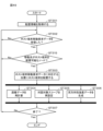
- the process of step ST315 is performed after step ST302.
- step ST315 it is determined whether or not the migration destination corresponding to the host terminal migration request data is a node where the host terminal can be arranged. If the node can be arranged, the process proceeds to step ST303, and if the node cannot be arranged, the process returns to step ST302.
- the output unit may be, for example, a device that gives the user a tactile sensation (vibration, hardness, thermal sensation, texture, etc.) or a device that gives the user an odor.
- a tactile sensation vibration, hardness, thermal sensation, texture, etc.
- control may be performed such that the vibration is increased or the smell is increased.
- the interactivity intensity data is generated based on the distance data and the dialogue target scope data has been described, but it may be generated based on either one.
- the dialogue target scope may be changed when the arrangement information is changed.
- the definition of the interaction target scope (for example, the range one layer below the host terminal) may be changed. Further, control may be performed such that not all of the arrangement information but only a part (for example, a hierarchy below a predetermined hierarchy) is changed.
- the host terminal or a predetermined client terminal may function as the server.
- the server obtains information about the interactivity strength, and based on the bidirectional strength, the output form in the output unit of at least one information processing terminal (for example, the host terminal or the client terminal) among the plurality of information processing terminals may be controlled to change the For example, the server generates control data for changing the output mode based on the interactivity strength, and transmits the generated control data to the host terminal and the client terminal.
- the output mode of the output unit is changed by the host terminal or the client terminal performing control according to the control data.
- the server may obtain the information about the interactivity strength from another server, or the server itself may generate the information about the interactivity strength based on the arrangement information. You may acquire it by doing.
- the present disclosure can also take the following configuration. (1) acquiring information about the interactivity strength based on arrangement information indicating the relationship between a plurality of information processing terminals, and based on the interactivity strength, the output unit of at least one information processing terminal among the plurality of information processing terminals; An information processing apparatus comprising a control unit that performs control to change an output form.
- the interactivity intensity data includes distance data indicating a distance between predetermined information processing terminals in the arrangement information, The information processing apparatus according to (1), wherein the control section performs control to change an output form of the output section according to the distance data.
- the control unit performs control to change the output form of the output unit so that the information corresponding to the information processing terminal is more abstractly represented as the distance data is larger, and the control unit changes the output form as the distance data is smaller.
- the information processing apparatus according to (2) wherein control is performed to change the output form of the output unit so that information corresponding to the information processing terminal is specifically expressed.
- the interactivity strength data includes dialogue target scope data indicating whether or not it is included in a dialogue target scope, which is a range in which interaction via the output unit is possible in the arrangement information, The information processing apparatus according to (2), wherein the control unit performs control to change an output form of the output unit according to the distance data and the dialogue target scope data.
- the control unit changes the output form of the output unit so that information corresponding to the predetermined information processing terminal is abstractly expressed. and when the predetermined information processing terminal is included in the dialogue target scope, the output form of the output unit is changed so that the information corresponding to the predetermined information processing terminal is specifically expressed.
- the information processing apparatus according to (4) which performs control to cause the (6)
- the information processing apparatus according to (4) or (5) wherein the dialogue target scope is set based on the distance data.
- the predetermined information processing terminal includes a host terminal arranged in the arrangement information.
- the predetermined information processing terminal includes a client terminal, The output unit outputs information corresponding to a response request from the client terminal, (4) The information processing apparatus according to (4), wherein the control unit performs control to change an output form of information corresponding to the response request based on the dialogue target scope data. (13) The information processing apparatus according to (12), wherein the control unit performs control to output the information corresponding to the response request in a different output form based on whether or not the client terminal is included in the dialogue target scope. (14) The information processing apparatus according to any one of (1) to (13), wherein the arrangement information is defined according to attribute information input from each information processing terminal. (15) The information processing apparatus according to any one of (1) to (14), wherein the arrangement information is changeable.
- the information processing apparatus includes a device that displays video, The information processing apparatus according to any one of (1) to (16), wherein the control unit changes an output form of the video.
- the output unit includes a device that reproduces audio, The information processing apparatus according to any one of (1) to (17), wherein the control unit changes an output form of the sound.
- a control unit acquires information about interactivity strength based on arrangement information indicating a relationship between a plurality of information processing terminals, and controls at least one information processing terminal among the plurality of information processing terminals based on the interactivity strength.
- a control unit acquires information about interactivity strength based on arrangement information indicating a relationship between a plurality of information processing terminals, and controls at least one information processing terminal among the plurality of information processing terminals based on the interactivity strength.
Landscapes
- Engineering & Computer Science (AREA)
- Theoretical Computer Science (AREA)
- General Engineering & Computer Science (AREA)
- Physics & Mathematics (AREA)
- General Physics & Mathematics (AREA)
- Multimedia (AREA)
- Human Computer Interaction (AREA)
- Signal Processing (AREA)
- Computer Networks & Wireless Communication (AREA)
- Educational Administration (AREA)
- Educational Technology (AREA)
- Business, Economics & Management (AREA)
- Information Transfer Between Computers (AREA)
- Two-Way Televisions, Distribution Of Moving Picture Or The Like (AREA)
Priority Applications (3)
| Application Number | Priority Date | Filing Date | Title |
|---|---|---|---|
| JP2023542196A JPWO2023021743A1 (cg-RX-API-DMAC7.html) | 2021-08-17 | 2022-03-02 | |
| US18/682,511 US20240348465A1 (en) | 2021-08-17 | 2022-03-02 | Information processing device, information processing method, and program |
| CN202280055501.2A CN117795948A (zh) | 2021-08-17 | 2022-03-02 | 信息处理装置、信息处理方法和程序 |
Applications Claiming Priority (2)
| Application Number | Priority Date | Filing Date | Title |
|---|---|---|---|
| JP2021-132992 | 2021-08-17 | ||
| JP2021132992 | 2021-08-17 |
Publications (1)
| Publication Number | Publication Date |
|---|---|
| WO2023021743A1 true WO2023021743A1 (ja) | 2023-02-23 |
Family
ID=85240347
Family Applications (1)
| Application Number | Title | Priority Date | Filing Date |
|---|---|---|---|
| PCT/JP2022/008814 Ceased WO2023021743A1 (ja) | 2021-08-17 | 2022-03-02 | 情報処理装置、情報処理方法およびプログラム |
Country Status (4)
| Country | Link |
|---|---|
| US (1) | US20240348465A1 (cg-RX-API-DMAC7.html) |
| JP (1) | JPWO2023021743A1 (cg-RX-API-DMAC7.html) |
| CN (1) | CN117795948A (cg-RX-API-DMAC7.html) |
| WO (1) | WO2023021743A1 (cg-RX-API-DMAC7.html) |
Citations (3)
| Publication number | Priority date | Publication date | Assignee | Title |
|---|---|---|---|---|
| JP2000165831A (ja) * | 1998-11-30 | 2000-06-16 | Nec Corp | 多地点テレビ会議システム |
| JP2006279588A (ja) * | 2005-03-29 | 2006-10-12 | Yamaha Corp | 多地点通信会議用端末 |
| JP2011107329A (ja) * | 2009-11-16 | 2011-06-02 | Wao Corporation | サーバ装置、双方向教育方法、およびプログラム |
Family Cites Families (1)
| Publication number | Priority date | Publication date | Assignee | Title |
|---|---|---|---|---|
| US20080137553A1 (en) * | 2006-12-12 | 2008-06-12 | Yi-Shou Hsu | Method of automatic certification and secure configuration of a wlan system and transmission device thereof |
-
2022
- 2022-03-02 US US18/682,511 patent/US20240348465A1/en not_active Abandoned
- 2022-03-02 CN CN202280055501.2A patent/CN117795948A/zh not_active Withdrawn
- 2022-03-02 WO PCT/JP2022/008814 patent/WO2023021743A1/ja not_active Ceased
- 2022-03-02 JP JP2023542196A patent/JPWO2023021743A1/ja not_active Ceased
Patent Citations (3)
| Publication number | Priority date | Publication date | Assignee | Title |
|---|---|---|---|---|
| JP2000165831A (ja) * | 1998-11-30 | 2000-06-16 | Nec Corp | 多地点テレビ会議システム |
| JP2006279588A (ja) * | 2005-03-29 | 2006-10-12 | Yamaha Corp | 多地点通信会議用端末 |
| JP2011107329A (ja) * | 2009-11-16 | 2011-06-02 | Wao Corporation | サーバ装置、双方向教育方法、およびプログラム |
Also Published As
| Publication number | Publication date |
|---|---|
| JPWO2023021743A1 (cg-RX-API-DMAC7.html) | 2023-02-23 |
| CN117795948A (zh) | 2024-03-29 |
| US20240348465A1 (en) | 2024-10-17 |
Similar Documents
| Publication | Publication Date | Title |
|---|---|---|
| Tsepapadakis et al. | Are you talking to me? An Audio Augmented Reality conversational guide for cultural heritage | |
| KR102507260B1 (ko) | 메타버스 가상공간의 강사 아바타 생성을 위한 서비스 서버 및 그 방법 | |
| JP2022046670A (ja) | 対話型拡張現実表示を表示するためのシステム、方法、及び媒体 | |
| KR20220027187A (ko) | 장면 인터랙션 방법 및 장치, 전자 장치 및 컴퓨터 저장 매체 | |
| KR20220160699A (ko) | 내비게이션 가능한 아바타들이 있는 웹 기반 화상 회의 가상 환경 및 그 응용들 | |
| US20050254505A1 (en) | Smart digital modules and smart digital wall surfaces combining the same, and context aware interactive multimedia system using the same and operation method thereof | |
| KR102668429B1 (ko) | 전자장치 및 그 제어방법 | |
| Langlotz et al. | Audio stickies: visually-guided spatial audio annotations on a mobile augmented reality platform | |
| KR102476444B1 (ko) | 비대면 환경에서의 사용자 간에 실시간 상호작용이 가능한 원격방식의 그림 제작 서비스를 제공하는 방법 | |
| KR20210022579A (ko) | 정보 처리 장치 및 정보 처리 방법, 그리고 정보 처리 시스템 | |
| JP2019036953A (ja) | 映像通話を利用した道案内方法およびシステム | |
| Khan | Advancements and challenges in 360 augmented reality video streaming: A comprehensive review | |
| US20230413003A1 (en) | Audio processing in a virtual environment | |
| JP7841578B2 (ja) | 配信システム | |
| JP2005538638A (ja) | ワイヤレス投影システム | |
| Feitl et al. | Accessible electrostatic surface haptics: Towards an interactive audiotactile map interface for people with visual impairments | |
| Shidende et al. | A personalized captioning strategy for the deaf and hard-of-hearing users in an augmented reality environment | |
| WO2022231709A1 (en) | Integrating overlaid digital content into data via processing circuitry using an audio buffer | |
| KR20220168536A (ko) | 인공지능 대화 엔진 학습 방법 및 그 시스템 | |
| US20240296748A1 (en) | System and method for language skill development using a virtual reality environment | |
| CN117795948A (zh) | 信息处理装置、信息处理方法和程序 | |
| CN117612417A (zh) | 基于ar技术的课堂教学方法 | |
| US11816759B1 (en) | Split applications in a multi-user communication session | |
| Paratore et al. | Haptic-based cognitive mapping to support shopping malls exploration | |
| JP2022098220A (ja) | 学習支援方法、学習支援システム、学習支援装置、学習支援プログラム |
Legal Events
| Date | Code | Title | Description |
|---|---|---|---|
| 121 | Ep: the epo has been informed by wipo that ep was designated in this application |
Ref document number: 22858068 Country of ref document: EP Kind code of ref document: A1 |
|
| WWE | Wipo information: entry into national phase |
Ref document number: 2023542196 Country of ref document: JP |
|
| WWE | Wipo information: entry into national phase |
Ref document number: 202280055501.2 Country of ref document: CN |
|
| WWE | Wipo information: entry into national phase |
Ref document number: 18682511 Country of ref document: US |
|
| NENP | Non-entry into the national phase |
Ref country code: DE |
|
| 122 | Ep: pct application non-entry in european phase |
Ref document number: 22858068 Country of ref document: EP Kind code of ref document: A1 |