WO2023017601A1 - Electrochemical cell, power generation method using electrochemical cell, and method for producing hydrogen gas using electrochemical cell - Google Patents
Electrochemical cell, power generation method using electrochemical cell, and method for producing hydrogen gas using electrochemical cell Download PDFInfo
- Publication number
- WO2023017601A1 WO2023017601A1 PCT/JP2021/029742 JP2021029742W WO2023017601A1 WO 2023017601 A1 WO2023017601 A1 WO 2023017601A1 JP 2021029742 W JP2021029742 W JP 2021029742W WO 2023017601 A1 WO2023017601 A1 WO 2023017601A1
- Authority
- WO
- WIPO (PCT)
- Prior art keywords
- electrochemical cell
- cathode
- hydrogen
- anode
- proton conductor
- Prior art date
Links
- UFHFLCQGNIYNRP-UHFFFAOYSA-N Hydrogen Chemical compound [H][H] UFHFLCQGNIYNRP-UHFFFAOYSA-N 0.000 title claims abstract description 96
- 238000000034 method Methods 0.000 title claims abstract description 34
- 238000010248 power generation Methods 0.000 title claims abstract description 29
- 238000004519 manufacturing process Methods 0.000 title claims abstract description 17
- 239000000446 fuel Substances 0.000 claims abstract description 117
- 239000004020 conductor Substances 0.000 claims abstract description 102
- HBBGRARXTFLTSG-UHFFFAOYSA-N Lithium ion Chemical compound [Li+] HBBGRARXTFLTSG-UHFFFAOYSA-N 0.000 claims abstract description 30
- 229910001416 lithium ion Inorganic materials 0.000 claims abstract description 30
- 239000003054 catalyst Substances 0.000 claims description 108
- 229910052739 hydrogen Inorganic materials 0.000 claims description 70
- 239000001257 hydrogen Substances 0.000 claims description 70
- UAEPNZWRGJTJPN-UHFFFAOYSA-N methylcyclohexane Chemical compound CC1CCCCC1 UAEPNZWRGJTJPN-UHFFFAOYSA-N 0.000 claims description 66
- BASFCYQUMIYNBI-UHFFFAOYSA-N platinum Chemical compound [Pt] BASFCYQUMIYNBI-UHFFFAOYSA-N 0.000 claims description 56
- 238000006356 dehydrogenation reaction Methods 0.000 claims description 53
- OKKJLVBELUTLKV-UHFFFAOYSA-N Methanol Chemical compound OC OKKJLVBELUTLKV-UHFFFAOYSA-N 0.000 claims description 48
- QGZKDVFQNNGYKY-UHFFFAOYSA-N Ammonia Chemical compound N QGZKDVFQNNGYKY-UHFFFAOYSA-N 0.000 claims description 36
- GYNNXHKOJHMOHS-UHFFFAOYSA-N methyl-cycloheptane Natural products CC1CCCCCC1 GYNNXHKOJHMOHS-UHFFFAOYSA-N 0.000 claims description 33
- BDAGIHXWWSANSR-UHFFFAOYSA-N methanoic acid Natural products OC=O BDAGIHXWWSANSR-UHFFFAOYSA-N 0.000 claims description 32
- PNEYBMLMFCGWSK-UHFFFAOYSA-N aluminium oxide Inorganic materials [O-2].[O-2].[O-2].[Al+3].[Al+3] PNEYBMLMFCGWSK-UHFFFAOYSA-N 0.000 claims description 29
- 229910052697 platinum Inorganic materials 0.000 claims description 27
- LCGLNKUTAGEVQW-UHFFFAOYSA-N Dimethyl ether Chemical compound COC LCGLNKUTAGEVQW-UHFFFAOYSA-N 0.000 claims description 26
- 150000001875 compounds Chemical class 0.000 claims description 26
- XLYOFNOQVPJJNP-UHFFFAOYSA-N water Chemical compound O XLYOFNOQVPJJNP-UHFFFAOYSA-N 0.000 claims description 23
- 239000002245 particle Substances 0.000 claims description 20
- 229910021529 ammonia Inorganic materials 0.000 claims description 18
- 238000005868 electrolysis reaction Methods 0.000 claims description 18
- OSWFIVFLDKOXQC-UHFFFAOYSA-N 4-(3-methoxyphenyl)aniline Chemical compound COC1=CC=CC(C=2C=CC(N)=CC=2)=C1 OSWFIVFLDKOXQC-UHFFFAOYSA-N 0.000 claims description 16
- 235000019253 formic acid Nutrition 0.000 claims description 16
- 229930195733 hydrocarbon Natural products 0.000 claims description 15
- 150000002430 hydrocarbons Chemical class 0.000 claims description 15
- 239000001301 oxygen Substances 0.000 claims description 14
- 229910052760 oxygen Inorganic materials 0.000 claims description 14
- NNBZCPXTIHJBJL-UHFFFAOYSA-N decalin Chemical compound C1CCCC2CCCCC21 NNBZCPXTIHJBJL-UHFFFAOYSA-N 0.000 claims description 12
- -1 hydride compound Chemical class 0.000 claims description 12
- MEBONNVPKOBPEA-UHFFFAOYSA-N 1,1,2-trimethylcyclohexane Chemical compound CC1CCCCC1(C)C MEBONNVPKOBPEA-UHFFFAOYSA-N 0.000 claims description 10
- 239000004215 Carbon black (E152) Substances 0.000 claims description 10
- PXXNTAGJWPJAGM-UHFFFAOYSA-N vertaline Natural products C1C2C=3C=C(OC)C(OC)=CC=3OC(C=C3)=CC=C3CCC(=O)OC1CC1N2CCCC1 PXXNTAGJWPJAGM-UHFFFAOYSA-N 0.000 claims description 6
- QWUWMCYKGHVNAV-UHFFFAOYSA-N 1,2-dihydrostilbene Chemical compound C=1C=CC=CC=1CCC1=CC=CC=C1 QWUWMCYKGHVNAV-UHFFFAOYSA-N 0.000 claims description 5
- XDTMQSROBMDMFD-UHFFFAOYSA-N Cyclohexane Chemical compound C1CCCCC1 XDTMQSROBMDMFD-UHFFFAOYSA-N 0.000 claims description 5
- 125000003118 aryl group Chemical group 0.000 claims description 5
- 230000003915 cell function Effects 0.000 claims description 3
- 229910005833 GeO4 Inorganic materials 0.000 abstract description 3
- 239000011701 zinc Substances 0.000 description 60
- 239000007789 gas Substances 0.000 description 45
- 238000006243 chemical reaction Methods 0.000 description 34
- YXFVVABEGXRONW-UHFFFAOYSA-N Toluene Chemical compound CC1=CC=CC=C1 YXFVVABEGXRONW-UHFFFAOYSA-N 0.000 description 33
- 238000009792 diffusion process Methods 0.000 description 28
- QTBSBXVTEAMEQO-UHFFFAOYSA-N Acetic acid Chemical compound CC(O)=O QTBSBXVTEAMEQO-UHFFFAOYSA-N 0.000 description 24
- 238000005342 ion exchange Methods 0.000 description 24
- CURLTUGMZLYLDI-UHFFFAOYSA-N Carbon dioxide Chemical compound O=C=O CURLTUGMZLYLDI-UHFFFAOYSA-N 0.000 description 18
- 239000007784 solid electrolyte Substances 0.000 description 13
- 239000000126 substance Substances 0.000 description 13
- 239000000843 powder Substances 0.000 description 12
- 229910005317 Li14Zn(GeO4)4 Inorganic materials 0.000 description 10
- 229910002092 carbon dioxide Inorganic materials 0.000 description 9
- 239000001569 carbon dioxide Substances 0.000 description 9
- QPTUMKXXAAHOOE-UHFFFAOYSA-M cesium;hydron;phosphate Chemical compound [Cs+].OP(O)([O-])=O QPTUMKXXAAHOOE-UHFFFAOYSA-M 0.000 description 9
- XLOMVQKBTHCTTD-UHFFFAOYSA-N Zinc monoxide Chemical compound [Zn]=O XLOMVQKBTHCTTD-UHFFFAOYSA-N 0.000 description 8
- 239000003125 aqueous solvent Substances 0.000 description 8
- WPYMKLBDIGXBTP-UHFFFAOYSA-N benzoic acid Chemical compound OC(=O)C1=CC=CC=C1 WPYMKLBDIGXBTP-UHFFFAOYSA-N 0.000 description 8
- 229910021293 PO 4 Inorganic materials 0.000 description 7
- 239000003014 ion exchange membrane Substances 0.000 description 7
- 238000000465 moulding Methods 0.000 description 7
- MUBZPKHOEPUJKR-UHFFFAOYSA-N Oxalic acid Chemical compound OC(=O)C(O)=O MUBZPKHOEPUJKR-UHFFFAOYSA-N 0.000 description 6
- QVGXLLKOCUKJST-UHFFFAOYSA-N atomic oxygen Chemical compound [O] QVGXLLKOCUKJST-UHFFFAOYSA-N 0.000 description 6
- 230000000052 comparative effect Effects 0.000 description 6
- 238000000354 decomposition reaction Methods 0.000 description 6
- 239000007788 liquid Substances 0.000 description 6
- 239000011148 porous material Substances 0.000 description 6
- 238000002407 reforming Methods 0.000 description 6
- LFQSCWFLJHTTHZ-UHFFFAOYSA-N Ethanol Chemical compound CCO LFQSCWFLJHTTHZ-UHFFFAOYSA-N 0.000 description 5
- 229920000557 Nafion® Polymers 0.000 description 5
- 239000002253 acid Substances 0.000 description 5
- 239000007864 aqueous solution Substances 0.000 description 5
- 230000005611 electricity Effects 0.000 description 5
- 150000004678 hydrides Chemical class 0.000 description 5
- 239000008188 pellet Substances 0.000 description 5
- 230000036647 reaction Effects 0.000 description 5
- 239000007787 solid Substances 0.000 description 5
- 238000012546 transfer Methods 0.000 description 5
- IJGRMHOSHXDMSA-UHFFFAOYSA-N Atomic nitrogen Chemical compound N#N IJGRMHOSHXDMSA-UHFFFAOYSA-N 0.000 description 4
- 239000005711 Benzoic acid Substances 0.000 description 4
- IAZDPXIOMUYVGZ-UHFFFAOYSA-N Dimethylsulphoxide Chemical compound CS(C)=O IAZDPXIOMUYVGZ-UHFFFAOYSA-N 0.000 description 4
- VGGSQFUCUMXWEO-UHFFFAOYSA-N Ethene Chemical compound C=C VGGSQFUCUMXWEO-UHFFFAOYSA-N 0.000 description 4
- 239000005977 Ethylene Substances 0.000 description 4
- AFVFQIVMOAPDHO-UHFFFAOYSA-N Methanesulfonic acid Chemical compound CS(O)(=O)=O AFVFQIVMOAPDHO-UHFFFAOYSA-N 0.000 description 4
- NBIIXXVUZAFLBC-UHFFFAOYSA-N Phosphoric acid Chemical compound OP(O)(O)=O NBIIXXVUZAFLBC-UHFFFAOYSA-N 0.000 description 4
- MCMNRKCIXSYSNV-UHFFFAOYSA-N Zirconium dioxide Chemical compound O=[Zr]=O MCMNRKCIXSYSNV-UHFFFAOYSA-N 0.000 description 4
- 235000010233 benzoic acid Nutrition 0.000 description 4
- 230000000694 effects Effects 0.000 description 4
- 238000010304 firing Methods 0.000 description 4
- 239000012528 membrane Substances 0.000 description 4
- 229910052751 metal Inorganic materials 0.000 description 4
- 239000002184 metal Substances 0.000 description 4
- 239000002904 solvent Substances 0.000 description 4
- 125000006850 spacer group Chemical group 0.000 description 4
- JOXIMZWYDAKGHI-UHFFFAOYSA-N toluene-4-sulfonic acid Chemical compound CC1=CC=C(S(O)(=O)=O)C=C1 JOXIMZWYDAKGHI-UHFFFAOYSA-N 0.000 description 4
- 239000011787 zinc oxide Substances 0.000 description 4
- OKTJSMMVPCPJKN-UHFFFAOYSA-N Carbon Chemical compound [C] OKTJSMMVPCPJKN-UHFFFAOYSA-N 0.000 description 3
- KFZMGEQAYNKOFK-UHFFFAOYSA-N Isopropanol Chemical compound CC(C)O KFZMGEQAYNKOFK-UHFFFAOYSA-N 0.000 description 3
- 239000002227 LISICON Substances 0.000 description 3
- ZMXDDKWLCZADIW-UHFFFAOYSA-N N,N-Dimethylformamide Chemical compound CN(C)C=O ZMXDDKWLCZADIW-UHFFFAOYSA-N 0.000 description 3
- LRHPLDYGYMQRHN-UHFFFAOYSA-N N-Butanol Chemical compound CCCCO LRHPLDYGYMQRHN-UHFFFAOYSA-N 0.000 description 3
- NINIDFKCEFEMDL-UHFFFAOYSA-N Sulfur Chemical compound [S] NINIDFKCEFEMDL-UHFFFAOYSA-N 0.000 description 3
- 239000002152 aqueous-organic solution Substances 0.000 description 3
- 238000009835 boiling Methods 0.000 description 3
- 229910052799 carbon Inorganic materials 0.000 description 3
- 238000010586 diagram Methods 0.000 description 3
- 239000002828 fuel tank Substances 0.000 description 3
- 230000006870 function Effects 0.000 description 3
- 150000002500 ions Chemical class 0.000 description 3
- 229910052741 iridium Inorganic materials 0.000 description 3
- GKOZUEZYRPOHIO-UHFFFAOYSA-N iridium atom Chemical compound [Ir] GKOZUEZYRPOHIO-UHFFFAOYSA-N 0.000 description 3
- 239000000463 material Substances 0.000 description 3
- 238000005259 measurement Methods 0.000 description 3
- VNWKTOKETHGBQD-UHFFFAOYSA-N methane Chemical compound C VNWKTOKETHGBQD-UHFFFAOYSA-N 0.000 description 3
- 239000000203 mixture Substances 0.000 description 3
- 229910000510 noble metal Inorganic materials 0.000 description 3
- 239000003960 organic solvent Substances 0.000 description 3
- BDERNNFJNOPAEC-UHFFFAOYSA-N propan-1-ol Chemical compound CCCO BDERNNFJNOPAEC-UHFFFAOYSA-N 0.000 description 3
- 239000002994 raw material Substances 0.000 description 3
- 230000009467 reduction Effects 0.000 description 3
- RTZZCYNQPHTPPL-UHFFFAOYSA-N 3-nitrophenol Chemical compound OC1=CC=CC([N+]([O-])=O)=C1 RTZZCYNQPHTPPL-UHFFFAOYSA-N 0.000 description 2
- UGFAIRIUMAVXCW-UHFFFAOYSA-N Carbon monoxide Chemical compound [O+]#[C-] UGFAIRIUMAVXCW-UHFFFAOYSA-N 0.000 description 2
- BVKZGUZCCUSVTD-UHFFFAOYSA-L Carbonate Chemical compound [O-]C([O-])=O BVKZGUZCCUSVTD-UHFFFAOYSA-L 0.000 description 2
- WHXSMMKQMYFTQS-UHFFFAOYSA-N Lithium Chemical compound [Li] WHXSMMKQMYFTQS-UHFFFAOYSA-N 0.000 description 2
- WMFOQBRAJBCJND-UHFFFAOYSA-M Lithium hydroxide Chemical compound [Li+].[OH-] WMFOQBRAJBCJND-UHFFFAOYSA-M 0.000 description 2
- PXHVJJICTQNCMI-UHFFFAOYSA-N Nickel Chemical compound [Ni] PXHVJJICTQNCMI-UHFFFAOYSA-N 0.000 description 2
- KDLHZDBZIXYQEI-UHFFFAOYSA-N Palladium Chemical compound [Pd] KDLHZDBZIXYQEI-UHFFFAOYSA-N 0.000 description 2
- ATUOYWHBWRKTHZ-UHFFFAOYSA-N Propane Chemical compound CCC ATUOYWHBWRKTHZ-UHFFFAOYSA-N 0.000 description 2
- KJTLSVCANCCWHF-UHFFFAOYSA-N Ruthenium Chemical compound [Ru] KJTLSVCANCCWHF-UHFFFAOYSA-N 0.000 description 2
- WYURNTSHIVDZCO-UHFFFAOYSA-N Tetrahydrofuran Chemical compound C1CCOC1 WYURNTSHIVDZCO-UHFFFAOYSA-N 0.000 description 2
- 229910052783 alkali metal Inorganic materials 0.000 description 2
- 150000001340 alkali metals Chemical class 0.000 description 2
- 229910000147 aluminium phosphate Inorganic materials 0.000 description 2
- 230000015572 biosynthetic process Effects 0.000 description 2
- 229910002091 carbon monoxide Inorganic materials 0.000 description 2
- 238000001816 cooling Methods 0.000 description 2
- 239000012024 dehydrating agents Substances 0.000 description 2
- 239000003792 electrolyte Substances 0.000 description 2
- YBMRDBCBODYGJE-UHFFFAOYSA-N germanium oxide Inorganic materials O=[Ge]=O YBMRDBCBODYGJE-UHFFFAOYSA-N 0.000 description 2
- 229910052744 lithium Inorganic materials 0.000 description 2
- XGZVUEUWXADBQD-UHFFFAOYSA-L lithium carbonate Chemical compound [Li+].[Li+].[O-]C([O-])=O XGZVUEUWXADBQD-UHFFFAOYSA-L 0.000 description 2
- 229910052808 lithium carbonate Inorganic materials 0.000 description 2
- IIPYXGDZVMZOAP-UHFFFAOYSA-N lithium nitrate Chemical compound [Li+].[O-][N+]([O-])=O IIPYXGDZVMZOAP-UHFFFAOYSA-N 0.000 description 2
- 229940098779 methanesulfonic acid Drugs 0.000 description 2
- 239000004570 mortar (masonry) Substances 0.000 description 2
- 229910052757 nitrogen Inorganic materials 0.000 description 2
- 235000006408 oxalic acid Nutrition 0.000 description 2
- PVADDRMAFCOOPC-UHFFFAOYSA-N oxogermanium Chemical compound [Ge]=O PVADDRMAFCOOPC-UHFFFAOYSA-N 0.000 description 2
- 239000012071 phase Substances 0.000 description 2
- 239000005518 polymer electrolyte Substances 0.000 description 2
- 229920005597 polymer membrane Polymers 0.000 description 2
- 238000010298 pulverizing process Methods 0.000 description 2
- 238000006057 reforming reaction Methods 0.000 description 2
- 229910052707 ruthenium Inorganic materials 0.000 description 2
- 239000002915 spent fuel radioactive waste Substances 0.000 description 2
- 238000003756 stirring Methods 0.000 description 2
- 229910052717 sulfur Inorganic materials 0.000 description 2
- 239000011593 sulfur Substances 0.000 description 2
- 238000003786 synthesis reaction Methods 0.000 description 2
- 229920000049 Carbon (fiber) Polymers 0.000 description 1
- VYZAMTAEIAYCRO-UHFFFAOYSA-N Chromium Chemical compound [Cr] VYZAMTAEIAYCRO-UHFFFAOYSA-N 0.000 description 1
- RYGMFSIKBFXOCR-UHFFFAOYSA-N Copper Chemical compound [Cu] RYGMFSIKBFXOCR-UHFFFAOYSA-N 0.000 description 1
- MYMOFIZGZYHOMD-UHFFFAOYSA-N Dioxygen Chemical compound O=O MYMOFIZGZYHOMD-UHFFFAOYSA-N 0.000 description 1
- OTMSDBZUPAUEDD-UHFFFAOYSA-N Ethane Chemical compound CC OTMSDBZUPAUEDD-UHFFFAOYSA-N 0.000 description 1
- GYHNNYVSQQEPJS-UHFFFAOYSA-N Gallium Chemical compound [Ga] GYHNNYVSQQEPJS-UHFFFAOYSA-N 0.000 description 1
- 229910006111 GeCl2 Inorganic materials 0.000 description 1
- 229910005793 GeO 2 Inorganic materials 0.000 description 1
- DGAQECJNVWCQMB-PUAWFVPOSA-M Ilexoside XXIX Chemical compound C[C@@H]1CC[C@@]2(CC[C@@]3(C(=CC[C@H]4[C@]3(CC[C@@H]5[C@@]4(CC[C@@H](C5(C)C)OS(=O)(=O)[O-])C)C)[C@@H]2[C@]1(C)O)C)C(=O)O[C@H]6[C@@H]([C@H]([C@@H]([C@H](O6)CO)O)O)O.[Na+] DGAQECJNVWCQMB-PUAWFVPOSA-M 0.000 description 1
- 229910018119 Li 3 PO 4 Inorganic materials 0.000 description 1
- FUJCRWPEOMXPAD-UHFFFAOYSA-N Li2O Inorganic materials [Li+].[Li+].[O-2] FUJCRWPEOMXPAD-UHFFFAOYSA-N 0.000 description 1
- ZOKXTWBITQBERF-UHFFFAOYSA-N Molybdenum Chemical compound [Mo] ZOKXTWBITQBERF-UHFFFAOYSA-N 0.000 description 1
- OAICVXFJPJFONN-UHFFFAOYSA-N Phosphorus Chemical compound [P] OAICVXFJPJFONN-UHFFFAOYSA-N 0.000 description 1
- ZLMJMSJWJFRBEC-UHFFFAOYSA-N Potassium Chemical compound [K] ZLMJMSJWJFRBEC-UHFFFAOYSA-N 0.000 description 1
- 229910004283 SiO 4 Inorganic materials 0.000 description 1
- HCHKCACWOHOZIP-UHFFFAOYSA-N Zinc Chemical compound [Zn] HCHKCACWOHOZIP-UHFFFAOYSA-N 0.000 description 1
- 239000000010 aprotic solvent Substances 0.000 description 1
- 229910052795 boron group element Inorganic materials 0.000 description 1
- 239000001273 butane Substances 0.000 description 1
- 239000006227 byproduct Substances 0.000 description 1
- 239000004917 carbon fiber Substances 0.000 description 1
- 229910052800 carbon group element Inorganic materials 0.000 description 1
- 239000003575 carbonaceous material Substances 0.000 description 1
- 238000010349 cathodic reaction Methods 0.000 description 1
- CETPSERCERDGAM-UHFFFAOYSA-N ceric oxide Chemical compound O=[Ce]=O CETPSERCERDGAM-UHFFFAOYSA-N 0.000 description 1
- 229910000422 cerium(IV) oxide Inorganic materials 0.000 description 1
- 230000008859 change Effects 0.000 description 1
- 239000003153 chemical reaction reagent Substances 0.000 description 1
- 229910052804 chromium Inorganic materials 0.000 description 1
- 239000011651 chromium Substances 0.000 description 1
- 229910017052 cobalt Inorganic materials 0.000 description 1
- 239000010941 cobalt Substances 0.000 description 1
- GUTLYIVDDKVIGB-UHFFFAOYSA-N cobalt atom Chemical compound [Co] GUTLYIVDDKVIGB-UHFFFAOYSA-N 0.000 description 1
- 238000002485 combustion reaction Methods 0.000 description 1
- 239000000805 composite resin Substances 0.000 description 1
- 238000007906 compression Methods 0.000 description 1
- 230000006835 compression Effects 0.000 description 1
- 239000000498 cooling water Substances 0.000 description 1
- 229910052802 copper Inorganic materials 0.000 description 1
- 239000010949 copper Substances 0.000 description 1
- 230000008021 deposition Effects 0.000 description 1
- 238000003795 desorption Methods 0.000 description 1
- XUCJHNOBJLKZNU-UHFFFAOYSA-M dilithium;hydroxide Chemical compound [Li+].[Li+].[OH-] XUCJHNOBJLKZNU-UHFFFAOYSA-M 0.000 description 1
- 229910001882 dioxygen Inorganic materials 0.000 description 1
- 238000007599 discharging Methods 0.000 description 1
- 238000001035 drying Methods 0.000 description 1
- 239000010411 electrocatalyst Substances 0.000 description 1
- 238000003487 electrochemical reaction Methods 0.000 description 1
- 239000007772 electrode material Substances 0.000 description 1
- 238000011156 evaluation Methods 0.000 description 1
- 230000001747 exhibiting effect Effects 0.000 description 1
- 238000001914 filtration Methods 0.000 description 1
- 239000002803 fossil fuel Substances 0.000 description 1
- 229910052733 gallium Inorganic materials 0.000 description 1
- 229910052732 germanium Inorganic materials 0.000 description 1
- GNPVGFCGXDBREM-UHFFFAOYSA-N germanium atom Chemical compound [Ge] GNPVGFCGXDBREM-UHFFFAOYSA-N 0.000 description 1
- QHGIKMVOLGCZIP-UHFFFAOYSA-N germanium dichloride Chemical compound Cl[Ge]Cl QHGIKMVOLGCZIP-UHFFFAOYSA-N 0.000 description 1
- 229910001849 group 12 element Inorganic materials 0.000 description 1
- 238000010438 heat treatment Methods 0.000 description 1
- 239000010416 ion conductor Substances 0.000 description 1
- 229920000554 ionomer Polymers 0.000 description 1
- 239000011159 matrix material Substances 0.000 description 1
- 239000000155 melt Substances 0.000 description 1
- 150000002736 metal compounds Chemical class 0.000 description 1
- 239000013081 microcrystal Substances 0.000 description 1
- 229910052750 molybdenum Inorganic materials 0.000 description 1
- 239000011733 molybdenum Substances 0.000 description 1
- IJDNQMDRQITEOD-UHFFFAOYSA-N n-butane Chemical compound CCCC IJDNQMDRQITEOD-UHFFFAOYSA-N 0.000 description 1
- OFBQJSOFQDEBGM-UHFFFAOYSA-N n-pentane Natural products CCCCC OFBQJSOFQDEBGM-UHFFFAOYSA-N 0.000 description 1
- 229910052759 nickel Inorganic materials 0.000 description 1
- 239000012299 nitrogen atmosphere Substances 0.000 description 1
- 239000004745 nonwoven fabric Substances 0.000 description 1
- 229920000620 organic polymer Polymers 0.000 description 1
- 239000007800 oxidant agent Substances 0.000 description 1
- 230000001590 oxidative effect Effects 0.000 description 1
- 125000004430 oxygen atom Chemical group O* 0.000 description 1
- 229910052763 palladium Inorganic materials 0.000 description 1
- 229910052698 phosphorus Inorganic materials 0.000 description 1
- 239000011574 phosphorus Substances 0.000 description 1
- 229920001343 polytetrafluoroethylene Polymers 0.000 description 1
- 239000004810 polytetrafluoroethylene Substances 0.000 description 1
- 229910052700 potassium Inorganic materials 0.000 description 1
- 239000011591 potassium Substances 0.000 description 1
- 239000000047 product Substances 0.000 description 1
- 230000001737 promoting effect Effects 0.000 description 1
- 239000001294 propane Substances 0.000 description 1
- 238000010926 purge Methods 0.000 description 1
- 238000000746 purification Methods 0.000 description 1
- 239000000376 reactant Substances 0.000 description 1
- 230000036632 reaction speed Effects 0.000 description 1
- 230000001105 regulatory effect Effects 0.000 description 1
- 238000011160 research Methods 0.000 description 1
- 239000013557 residual solvent Substances 0.000 description 1
- 230000004044 response Effects 0.000 description 1
- 238000007789 sealing Methods 0.000 description 1
- 239000002002 slurry Substances 0.000 description 1
- 229910052708 sodium Inorganic materials 0.000 description 1
- 239000011734 sodium Substances 0.000 description 1
- 238000003746 solid phase reaction Methods 0.000 description 1
- 238000010532 solid phase synthesis reaction Methods 0.000 description 1
- 239000006104 solid solution Substances 0.000 description 1
- 229910001220 stainless steel Inorganic materials 0.000 description 1
- 239000010935 stainless steel Substances 0.000 description 1
- 150000003464 sulfur compounds Chemical class 0.000 description 1
- YLQBMQCUIZJEEH-UHFFFAOYSA-N tetrahydrofuran Natural products C=1C=COC=1 YLQBMQCUIZJEEH-UHFFFAOYSA-N 0.000 description 1
- 238000002411 thermogravimetry Methods 0.000 description 1
- 230000007704 transition Effects 0.000 description 1
- 238000004627 transmission electron microscopy Methods 0.000 description 1
- 229910052720 vanadium Inorganic materials 0.000 description 1
- GPPXJZIENCGNKB-UHFFFAOYSA-N vanadium Chemical compound [V]#[V] GPPXJZIENCGNKB-UHFFFAOYSA-N 0.000 description 1
- 238000007740 vapor deposition Methods 0.000 description 1
- 229910052725 zinc Inorganic materials 0.000 description 1
Images


Classifications
-
- H—ELECTRICITY
- H01—ELECTRIC ELEMENTS
- H01M—PROCESSES OR MEANS, e.g. BATTERIES, FOR THE DIRECT CONVERSION OF CHEMICAL ENERGY INTO ELECTRICAL ENERGY
- H01M8/00—Fuel cells; Manufacture thereof
- H01M8/10—Fuel cells with solid electrolytes
- H01M8/12—Fuel cells with solid electrolytes operating at high temperature, e.g. with stabilised ZrO2 electrolyte
- H01M8/124—Fuel cells with solid electrolytes operating at high temperature, e.g. with stabilised ZrO2 electrolyte characterised by the process of manufacturing or by the material of the electrolyte
- H01M8/1246—Fuel cells with solid electrolytes operating at high temperature, e.g. with stabilised ZrO2 electrolyte characterised by the process of manufacturing or by the material of the electrolyte the electrolyte consisting of oxides
-
- C—CHEMISTRY; METALLURGY
- C25—ELECTROLYTIC OR ELECTROPHORETIC PROCESSES; APPARATUS THEREFOR
- C25B—ELECTROLYTIC OR ELECTROPHORETIC PROCESSES FOR THE PRODUCTION OF COMPOUNDS OR NON-METALS; APPARATUS THEREFOR
- C25B1/00—Electrolytic production of inorganic compounds or non-metals
- C25B1/01—Products
- C25B1/02—Hydrogen or oxygen
- C25B1/04—Hydrogen or oxygen by electrolysis of water
- C25B1/042—Hydrogen or oxygen by electrolysis of water by electrolysis of steam
-
- C—CHEMISTRY; METALLURGY
- C25—ELECTROLYTIC OR ELECTROPHORETIC PROCESSES; APPARATUS THEREFOR
- C25B—ELECTROLYTIC OR ELECTROPHORETIC PROCESSES FOR THE PRODUCTION OF COMPOUNDS OR NON-METALS; APPARATUS THEREFOR
- C25B13/00—Diaphragms; Spacing elements
- C25B13/04—Diaphragms; Spacing elements characterised by the material
- C25B13/05—Diaphragms; Spacing elements characterised by the material based on inorganic materials
- C25B13/07—Diaphragms; Spacing elements characterised by the material based on inorganic materials based on ceramics
-
- C—CHEMISTRY; METALLURGY
- C25—ELECTROLYTIC OR ELECTROPHORETIC PROCESSES; APPARATUS THEREFOR
- C25B—ELECTROLYTIC OR ELECTROPHORETIC PROCESSES FOR THE PRODUCTION OF COMPOUNDS OR NON-METALS; APPARATUS THEREFOR
- C25B15/00—Operating or servicing cells
- C25B15/08—Supplying or removing reactants or electrolytes; Regeneration of electrolytes
-
- C—CHEMISTRY; METALLURGY
- C25—ELECTROLYTIC OR ELECTROPHORETIC PROCESSES; APPARATUS THEREFOR
- C25B—ELECTROLYTIC OR ELECTROPHORETIC PROCESSES FOR THE PRODUCTION OF COMPOUNDS OR NON-METALS; APPARATUS THEREFOR
- C25B9/00—Cells or assemblies of cells; Constructional parts of cells; Assemblies of constructional parts, e.g. electrode-diaphragm assemblies; Process-related cell features
- C25B9/05—Pressure cells
-
- C—CHEMISTRY; METALLURGY
- C25—ELECTROLYTIC OR ELECTROPHORETIC PROCESSES; APPARATUS THEREFOR
- C25B—ELECTROLYTIC OR ELECTROPHORETIC PROCESSES FOR THE PRODUCTION OF COMPOUNDS OR NON-METALS; APPARATUS THEREFOR
- C25B9/00—Cells or assemblies of cells; Constructional parts of cells; Assemblies of constructional parts, e.g. electrode-diaphragm assemblies; Process-related cell features
- C25B9/17—Cells comprising dimensionally-stable non-movable electrodes; Assemblies of constructional parts thereof
- C25B9/19—Cells comprising dimensionally-stable non-movable electrodes; Assemblies of constructional parts thereof with diaphragms
-
- C—CHEMISTRY; METALLURGY
- C25—ELECTROLYTIC OR ELECTROPHORETIC PROCESSES; APPARATUS THEREFOR
- C25B—ELECTROLYTIC OR ELECTROPHORETIC PROCESSES FOR THE PRODUCTION OF COMPOUNDS OR NON-METALS; APPARATUS THEREFOR
- C25B9/00—Cells or assemblies of cells; Constructional parts of cells; Assemblies of constructional parts, e.g. electrode-diaphragm assemblies; Process-related cell features
- C25B9/60—Constructional parts of cells
- C25B9/65—Means for supplying current; Electrode connections; Electric inter-cell connections
-
- C—CHEMISTRY; METALLURGY
- C25—ELECTROLYTIC OR ELECTROPHORETIC PROCESSES; APPARATUS THEREFOR
- C25B—ELECTROLYTIC OR ELECTROPHORETIC PROCESSES FOR THE PRODUCTION OF COMPOUNDS OR NON-METALS; APPARATUS THEREFOR
- C25B9/00—Cells or assemblies of cells; Constructional parts of cells; Assemblies of constructional parts, e.g. electrode-diaphragm assemblies; Process-related cell features
- C25B9/70—Assemblies comprising two or more cells
- C25B9/73—Assemblies comprising two or more cells of the filter-press type
- C25B9/75—Assemblies comprising two or more cells of the filter-press type having bipolar electrodes
-
- C—CHEMISTRY; METALLURGY
- C25—ELECTROLYTIC OR ELECTROPHORETIC PROCESSES; APPARATUS THEREFOR
- C25B—ELECTROLYTIC OR ELECTROPHORETIC PROCESSES FOR THE PRODUCTION OF COMPOUNDS OR NON-METALS; APPARATUS THEREFOR
- C25B9/00—Cells or assemblies of cells; Constructional parts of cells; Assemblies of constructional parts, e.g. electrode-diaphragm assemblies; Process-related cell features
- C25B9/70—Assemblies comprising two or more cells
- C25B9/73—Assemblies comprising two or more cells of the filter-press type
- C25B9/77—Assemblies comprising two or more cells of the filter-press type having diaphragms
-
- H—ELECTRICITY
- H01—ELECTRIC ELEMENTS
- H01M—PROCESSES OR MEANS, e.g. BATTERIES, FOR THE DIRECT CONVERSION OF CHEMICAL ENERGY INTO ELECTRICAL ENERGY
- H01M12/00—Hybrid cells; Manufacture thereof
- H01M12/08—Hybrid cells; Manufacture thereof composed of a half-cell of a fuel-cell type and a half-cell of the secondary-cell type
-
- H—ELECTRICITY
- H01—ELECTRIC ELEMENTS
- H01M—PROCESSES OR MEANS, e.g. BATTERIES, FOR THE DIRECT CONVERSION OF CHEMICAL ENERGY INTO ELECTRICAL ENERGY
- H01M4/00—Electrodes
- H01M4/86—Inert electrodes with catalytic activity, e.g. for fuel cells
- H01M4/90—Selection of catalytic material
- H01M4/92—Metals of platinum group
- H01M4/925—Metals of platinum group supported on carriers, e.g. powder carriers
-
- H—ELECTRICITY
- H01—ELECTRIC ELEMENTS
- H01M—PROCESSES OR MEANS, e.g. BATTERIES, FOR THE DIRECT CONVERSION OF CHEMICAL ENERGY INTO ELECTRICAL ENERGY
- H01M8/00—Fuel cells; Manufacture thereof
- H01M8/06—Combination of fuel cells with means for production of reactants or for treatment of residues
- H01M8/0606—Combination of fuel cells with means for production of reactants or for treatment of residues with means for production of gaseous reactants
- H01M8/0612—Combination of fuel cells with means for production of reactants or for treatment of residues with means for production of gaseous reactants from carbon-containing material
- H01M8/0637—Direct internal reforming at the anode of the fuel cell
-
- H—ELECTRICITY
- H01—ELECTRIC ELEMENTS
- H01M—PROCESSES OR MEANS, e.g. BATTERIES, FOR THE DIRECT CONVERSION OF CHEMICAL ENERGY INTO ELECTRICAL ENERGY
- H01M8/00—Fuel cells; Manufacture thereof
- H01M8/06—Combination of fuel cells with means for production of reactants or for treatment of residues
- H01M8/0606—Combination of fuel cells with means for production of reactants or for treatment of residues with means for production of gaseous reactants
- H01M8/0656—Combination of fuel cells with means for production of reactants or for treatment of residues with means for production of gaseous reactants by electrochemical means
-
- H—ELECTRICITY
- H01—ELECTRIC ELEMENTS
- H01M—PROCESSES OR MEANS, e.g. BATTERIES, FOR THE DIRECT CONVERSION OF CHEMICAL ENERGY INTO ELECTRICAL ENERGY
- H01M8/00—Fuel cells; Manufacture thereof
- H01M8/10—Fuel cells with solid electrolytes
- H01M8/1009—Fuel cells with solid electrolytes with one of the reactants being liquid, solid or liquid-charged
-
- H—ELECTRICITY
- H01—ELECTRIC ELEMENTS
- H01M—PROCESSES OR MEANS, e.g. BATTERIES, FOR THE DIRECT CONVERSION OF CHEMICAL ENERGY INTO ELECTRICAL ENERGY
- H01M8/00—Fuel cells; Manufacture thereof
- H01M8/10—Fuel cells with solid electrolytes
- H01M8/12—Fuel cells with solid electrolytes operating at high temperature, e.g. with stabilised ZrO2 electrolyte
- H01M8/1213—Fuel cells with solid electrolytes operating at high temperature, e.g. with stabilised ZrO2 electrolyte characterised by the electrode/electrolyte combination or the supporting material
-
- H—ELECTRICITY
- H01—ELECTRIC ELEMENTS
- H01M—PROCESSES OR MEANS, e.g. BATTERIES, FOR THE DIRECT CONVERSION OF CHEMICAL ENERGY INTO ELECTRICAL ENERGY
- H01M8/00—Fuel cells; Manufacture thereof
- H01M8/10—Fuel cells with solid electrolytes
- H01M8/12—Fuel cells with solid electrolytes operating at high temperature, e.g. with stabilised ZrO2 electrolyte
- H01M8/1231—Fuel cells with solid electrolytes operating at high temperature, e.g. with stabilised ZrO2 electrolyte with both reactants being gaseous or vaporised
-
- H—ELECTRICITY
- H01—ELECTRIC ELEMENTS
- H01M—PROCESSES OR MEANS, e.g. BATTERIES, FOR THE DIRECT CONVERSION OF CHEMICAL ENERGY INTO ELECTRICAL ENERGY
- H01M8/00—Fuel cells; Manufacture thereof
- H01M8/22—Fuel cells in which the fuel is based on materials comprising carbon or oxygen or hydrogen and other elements; Fuel cells in which the fuel is based on materials comprising only elements other than carbon, oxygen or hydrogen
- H01M8/222—Fuel cells in which the fuel is based on compounds containing nitrogen, e.g. hydrazine, ammonia
-
- H—ELECTRICITY
- H01—ELECTRIC ELEMENTS
- H01M—PROCESSES OR MEANS, e.g. BATTERIES, FOR THE DIRECT CONVERSION OF CHEMICAL ENERGY INTO ELECTRICAL ENERGY
- H01M8/00—Fuel cells; Manufacture thereof
- H01M8/10—Fuel cells with solid electrolytes
- H01M8/12—Fuel cells with solid electrolytes operating at high temperature, e.g. with stabilised ZrO2 electrolyte
- H01M2008/1293—Fuel cells with solid oxide electrolytes
-
- H—ELECTRICITY
- H01—ELECTRIC ELEMENTS
- H01M—PROCESSES OR MEANS, e.g. BATTERIES, FOR THE DIRECT CONVERSION OF CHEMICAL ENERGY INTO ELECTRICAL ENERGY
- H01M2300/00—Electrolytes
- H01M2300/0017—Non-aqueous electrolytes
- H01M2300/0065—Solid electrolytes
- H01M2300/0068—Solid electrolytes inorganic
- H01M2300/0071—Oxides
- H01M2300/0074—Ion conductive at high temperature
-
- Y—GENERAL TAGGING OF NEW TECHNOLOGICAL DEVELOPMENTS; GENERAL TAGGING OF CROSS-SECTIONAL TECHNOLOGIES SPANNING OVER SEVERAL SECTIONS OF THE IPC; TECHNICAL SUBJECTS COVERED BY FORMER USPC CROSS-REFERENCE ART COLLECTIONS [XRACs] AND DIGESTS
- Y02—TECHNOLOGIES OR APPLICATIONS FOR MITIGATION OR ADAPTATION AGAINST CLIMATE CHANGE
- Y02E—REDUCTION OF GREENHOUSE GAS [GHG] EMISSIONS, RELATED TO ENERGY GENERATION, TRANSMISSION OR DISTRIBUTION
- Y02E60/00—Enabling technologies; Technologies with a potential or indirect contribution to GHG emissions mitigation
- Y02E60/30—Hydrogen technology
- Y02E60/50—Fuel cells
Landscapes
- Chemical & Material Sciences (AREA)
- Engineering & Computer Science (AREA)
- Electrochemistry (AREA)
- Chemical Kinetics & Catalysis (AREA)
- Manufacturing & Machinery (AREA)
- General Chemical & Material Sciences (AREA)
- Materials Engineering (AREA)
- Sustainable Energy (AREA)
- Sustainable Development (AREA)
- Life Sciences & Earth Sciences (AREA)
- Metallurgy (AREA)
- Organic Chemistry (AREA)
- Inorganic Chemistry (AREA)
- Ceramic Engineering (AREA)
- Fuel Cell (AREA)
- Electrolytic Production Of Non-Metals, Compounds, Apparatuses Therefor (AREA)
Abstract
Description
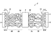
以下に、本発明の電気化学セルの実施形態について説明する。第1実施形態では、本発明の電気化学セルを燃料電池に適用した例について説明する。図1に示すように、燃料電池1は、互いに積層された複数の発電セル2を有する燃料電池スタック3を有する。図1及び図2に示すように、各発電セル2は、プロトン伝導体5と、プロトン伝導体5の一側に設けられたアノード6と、プロトン伝導体5の他側に設けられたカソード7と、プロトン伝導体5のアノード6側に設けられ、アノード室8を形成する第1セパレータ9と、プロトン伝導体5のカソード7側に設けられ、カソード室11を形成する第2セパレータ12とを有する。 (First embodiment)
Embodiments of the electrochemical cell of the present invention are described below. In the first embodiment, an example in which the electrochemical cell of the present invention is applied to a fuel cell will be described. As shown in FIG. 1, the


第1実施形態に係る燃料電池において、燃料はメチルシクロヘキサンに代えて、アンモニア、ギ酸、メタノール、ジメチルエーテルから構成される群から選択される少なくとも1つを含んでも良い。アンモニアを燃料として使用する場合、第1実施形態に係る燃料電池において、脱水素触媒を公知のアンモニア分解触媒に置換すると良い。アンモニア分解触媒は、アンモニアから水素と窒素とを生成する分解反応を促進する触媒であり、例えばルテニウム系触媒、コバルト系触媒又はニッケル系触媒であると良い。ギ酸を燃料として使用する場合、第1実施形態に係る燃料電池において、脱水素触媒を公知のギ酸改質触媒に置換すると良い。ギ酸改質触媒は、ギ酸から水素と二酸化炭素とを生成する改質反応を促進する触媒であり、例えばイリジウム錯体触媒であると良い。メタノールを燃料として使用する場合、第1実施形態に係る燃料電池において、脱水素触媒を公知のメタノール改質触媒に置換すると良い。メタノール改質触媒は、メタノールと水から水素と二酸化炭素とを生成する改質反応を促進する触媒であり、例えばイリジウム錯体触媒であると良い。ジメチルエーテルを燃料として使用する場合、第1実施形態に係る燃料電池において、脱水素触媒を公知のジメチルエーテル改質触媒に置換すると良い。アンモニア、ギ酸、メタノール、又はジメチルエーテルから水素を生成する反応は、いずれも吸熱反応であるため、カソード反応によって発生する熱を利用して反応を促進することができる。 (Second embodiment)
In the fuel cell according to the first embodiment, the fuel may contain at least one selected from the group consisting of ammonia, formic acid, methanol, and dimethyl ether instead of methylcyclohexane. When ammonia is used as the fuel, it is preferable to replace the dehydrogenation catalyst in the fuel cell according to the first embodiment with a known ammonia decomposition catalyst. The ammonia decomposition catalyst is a catalyst that promotes a decomposition reaction that produces hydrogen and nitrogen from ammonia, and may be, for example, a ruthenium-based catalyst, a cobalt-based catalyst, or a nickel-based catalyst. When formic acid is used as the fuel, it is preferable to replace the dehydrogenation catalyst with a known formic acid reforming catalyst in the fuel cell according to the first embodiment. The formic acid reforming catalyst is a catalyst that promotes a reforming reaction that produces hydrogen and carbon dioxide from formic acid, and is preferably an iridium complex catalyst, for example. When methanol is used as the fuel, it is preferable to replace the dehydrogenation catalyst in the fuel cell according to the first embodiment with a known methanol reforming catalyst. The methanol reforming catalyst is a catalyst that promotes a reforming reaction that produces hydrogen and carbon dioxide from methanol and water, and is preferably an iridium complex catalyst, for example. When dimethyl ether is used as the fuel, it is preferable to replace the dehydrogenation catalyst in the fuel cell according to the first embodiment with a known dimethyl ether reforming catalyst. Since any reaction that produces hydrogen from ammonia, formic acid, methanol, or dimethyl ether is an endothermic reaction, the heat generated by the cathode reaction can be used to promote the reaction.
第1実施形態に係る燃料電池の各発電セル2は、図4に示すように、電解槽50としても使用することができる。この場合、プロトン伝導体5はイオン交換膜として機能し、第1セパレータ9及び第2セパレータ12は容器52として機能する。アノード55は直流電源53の正極に接続され、カソード56は直流電源53の負極に接続されている。これにより、アノード55及びカソード56間に直流電圧が印加される。アノード55及びカソード56は容器54と電気的に絶縁されている。アノード室58及びカソード室59はプロトン伝導体5によって互いに区画されている。アノード室58には酸化されるべき第1物質が供給され、カソード室59には還元されるべき第2物質が供給されるとよい。 (Third embodiment)
Each
Li源として炭酸リチウム、Zn源として酸化亜鉛、Ge源として酸化ゲルマニウムを用いた。炭酸リチウム、酸化亜鉛、酸化ゲルマニウムを重量比で25:4:21の比率で加え、密閉容器内でエタノールとジルコニアボールと共に24時間微細化混合したスラリーを130℃で乾燥させて得られた粉末を、プレス機でペレットに成型した。このペレットをアルミナるつぼ内で空気中1150℃、5時間焼成した後に、マグネット乳鉢で2時間粉砕し、ふたたびペレットに成形してアルミナるつぼ内で空気中1150℃、5時間焼成した。焼成後のペレットを再びマグネット乳鉢で2時間粉砕してイオン交換前のLi14Zn(GeO4)4粉末を得た。 (Method for preparing Li 14 Zn(GeO 4 ) 4 )
Lithium carbonate was used as the Li source, zinc oxide as the Zn source, and germanium oxide as the Ge source. Lithium carbonate, zinc oxide, and germanium oxide were added in a weight ratio of 25:4:21, and the slurry was finely mixed with ethanol and zirconia balls for 24 hours in a closed vessel. , and molded into pellets in a press. The pellets were calcined in air at 1150° C. for 5 hours in an alumina crucible, pulverized in a magnetic mortar for 2 hours, formed into pellets again, and calcined in air at 1150° C. for 5 hours in an alumina crucible. The fired pellets were again pulverized in a magnet mortar for 2 hours to obtain Li 14 Zn(GeO 4 ) 4 powder before ion exchange.
イオン交換前のLi14Zn(GeO4)4粉末の試料2.5gを、非水系溶媒として脱水剤で水分を除去したトルエンを用い、ここにプロトン源として安息香酸を5mMの濃度となるように溶解させた非水系有機溶液100ml中で、24時間攪拌してイオン交換を実施した。イオン交換後にろ過して粉末を回収して、トルエンで洗浄後に、130℃で一晩真空乾燥することによって、実施例1のイオン交換粉末を得た。実施例1のプロトン伝導体の可動リチウムイオンのプロトンへのイオン交換率は52%であった。 (Example 1)
A 2.5 g sample of Li 14 Zn(GeO 4 ) 4 powder before ion exchange was mixed with toluene from which water was removed with a dehydrating agent as a non-aqueous solvent, and benzoic acid was added as a proton source to a concentration of 5 mM. Ion exchange was carried out in 100 ml of dissolved non-aqueous organic solution with stirring for 24 hours. After the ion exchange, the powder was collected by filtration, washed with toluene, and vacuum-dried at 130° C. overnight to obtain the ion-exchanged powder of Example 1. The ion exchange rate of mobile lithium ions to protons in the proton conductor of Example 1 was 52%.
イオン交換前のLi14Zn(GeO4)4粉末を重量の40倍の5mM酢酸水溶液中、室温下で24時間攪拌してイオン交換を行い、ろ過洗浄後に130℃の真空乾燥機で乾燥を行って比較例1のイオン交換体を得た。比較例1のプロトン伝導体の可動リチウムイオンのプロトンへのイオン交換率は100%であった。 (Comparative example 1)
The Li 14 Zn(GeO 4 ) 4 powder before ion exchange was stirred in a 5 mM acetic acid aqueous solution of 40 times its weight at room temperature for 24 hours to perform ion exchange, filtered and washed, and then dried in a vacuum dryer at 130°C. An ion exchanger of Comparative Example 1 was obtained. The ion exchange rate of mobile lithium ions to protons in the proton conductor of Comparative Example 1 was 100%.
実施例1及び比較例1のイオン交換体の導電率を測定した。測定は、電気化学評価装置(Solartron analytical社製、ModuLab)を使用して、10%加湿窒素雰囲気下で、直流四端子法及び交流二端子法で行った。測定結果を以下の表1に示す。

The conductivity of the ion exchangers of Example 1 and Comparative Example 1 was measured. The measurement was performed using an electrochemical evaluation device (ModuLab, manufactured by Solartron Analytical) in a 10% humidified nitrogen atmosphere by a direct current four-terminal method and an alternating current two-terminal method. The measurement results are shown in Table 1 below.
非水系溶媒としてジメチルスルホキシドを用いプロトン源としてm-ニトロフェノール、酢酸、安息香酸、p-トルエンスルホン酸、シュウ酸,メタンスルホン酸を用いて、5~100mMの範囲で濃度を変えて、実施例1と同様の方法でイオン交換操作を行った。その後、イオン交換操作を行ったLi14Zn(GeO4)4粉末の熱重量分析によって、イオン交換量を確認した。結果、各プロトン源に対して、イオン交換率は45~65%であった。 (Example 2)
Using dimethyl sulfoxide as a non-aqueous solvent and using m-nitrophenol, acetic acid, benzoic acid, p-toluenesulfonic acid, oxalic acid, and methanesulfonic acid as proton sources, and varying the concentration in the range of 5 to 100 mM, An ion exchange operation was performed in the same manner as in 1. After that, the amount of ion exchange was confirmed by thermogravimetric analysis of the Li 14 Zn(GeO 4 ) 4 powder subjected to the ion exchange operation. As a result, the ion exchange rate was 45-65% for each proton source.
2 :発電セル(電気化学セル)
3 :燃料電池スタック
5 :プロトン伝導体
6 :アノード
6A :アノード触媒層
6B :アノードガス拡散層
7 :カソード
7A :カソード触媒層
7B :カソードガス拡散層
8 :アノード室
9 :第1セパレータ
11 :カソード室
12 :第2セパレータ
25 :負極
26 :正極
41 :温度調節装置
50 :電解槽(電気化学セル)
52 :容器
53 :直流電源
54 :容器
55 :アノード
56 :カソード
57 :アノード
58 :アノード室
59 :カソード室 1: Fuel cell (electrochemical cell)
2: Power generation cell (electrochemical cell)
3: Fuel cell stack 5: Proton conductor 6:
52: Container 53: DC power supply 54: Container 55: Anode 56: Cathode 57: Anode 58: Anode chamber 59: Cathode chamber
Claims (22)
- 電気化学セルであって、
xが0以上の数であるLi14-2xZn1+x(GeO4)4のリチウムイオンの一部がプロトンに置換された(Li,H)14-2xZn1+x(GeO4)4であり、300℃において0.01S/cm以上の導電率を有するプロトン伝導体と、
前記プロトン伝導体の一側に設けられたアノードと、
前記プロトン伝導体の他側に設けられたカソードと、
前記プロトン伝導体の前記アノード側に設けられ、アノード室を形成する第1セパレータと、
前記プロトン伝導体の前記カソード側に設けられ、カソード室を形成する第2セパレータとを有する電気化学セル。 an electrochemical cell,
(Li, H) 14-2x Zn 1+x (GeO 4 ) 4 in which some of the lithium ions of Li 14-2x Zn 1+x (GeO 4 ) 4 where x is a number of 0 or more are substituted with protons; a proton conductor having a conductivity of 0.01 S/cm or higher at °C;
an anode provided on one side of the proton conductor;
a cathode provided on the other side of the proton conductor;
a first separator provided on the anode side of the proton conductor and forming an anode chamber;
and a second separator provided on the cathode side of the proton conductor and forming a cathode compartment. - 前記プロトン伝導体の温度を200℃以上600℃以下に維持する温度調節手段を有する請求項1に記載の電気化学セル。 The electrochemical cell according to claim 1, comprising temperature control means for maintaining the temperature of said proton conductor at 200°C or higher and 600°C or lower.
- 前記xは、0である請求項1又は2に記載の電気化学セル。 The electrochemical cell according to claim 1 or 2, wherein said x is 0.
- Li14-2xZn1+x(GeO4)4に含まれる可動リチウムイオンの40%以上70%以下がプロトンに置換されている請求項1~3のいずれか1つの項に記載の電気化学セル。 4. The electrochemical cell according to any one of claims 1 to 3, wherein 40% or more and 70% or less of mobile lithium ions contained in Li 14-2x Zn 1+x (GeO 4 ) 4 are replaced with protons.
- Li14-2xZn1+x(GeO4)4に含まれる可動リチウムイオンの50%以上60%以下がプロトンに置換されている請求項1~3のいずれか1つの項に記載の電気化学セル。 4. The electrochemical cell according to any one of claims 1 to 3, wherein 50% or more and 60% or less of mobile lithium ions contained in Li 14-2x Zn 1+x (GeO 4 ) 4 are replaced with protons.
- 前記プロトン伝導体、前記アノード、前記カソード、前記第1セパレータ、及び前記第2セパレータによって形成されるセルを複数有し、
前記セルの1つの前記第1セパレータは、前記セルの他の1つの前記第2セパレータと熱交換可能に接触している請求項1~5のいずれか1つの項に記載の電気化学セル。 having a plurality of cells formed by the proton conductor, the anode, the cathode, the first separator, and the second separator;
An electrochemical cell according to any one of claims 1 to 5, wherein said first separator of one of said cells is in heat exchange contact with said second separator of another one of said cells. - 前記アノード室に水素が供給され、
前記カソード室に空気が供給され、
前記アノード及び前記カソード間に起電力が生じ、当該電気化学セルが水素-酸素燃料電池として機能する請求項1~6のいずれか1つの項に記載の電気化学セル。 hydrogen is supplied to the anode chamber;
Air is supplied to the cathode chamber,
An electrochemical cell according to any one of claims 1 to 6, wherein an electromotive force is generated between said anode and said cathode, said electrochemical cell functioning as a hydrogen-oxygen fuel cell. - 前記アノード室に水素を含む水素含有化合物が供給され、
前記カソード室に空気が供給され、
前記アノード室に前記水素含有化合物から水素ガスを発生させる触媒を含む触媒層が設けられ、
前記アノード及び前記カソード間に起電力が生じ、当該電気化学セルが水素-酸素燃料電池として機能する請求項1~6のいずれか1つの項に記載の電気化学セル。 supplying a hydrogen-containing compound containing hydrogen to the anode chamber;
Air is supplied to the cathode chamber,
a catalyst layer containing a catalyst for generating hydrogen gas from the hydrogen-containing compound is provided in the anode chamber;
An electrochemical cell according to any one of claims 1 to 6, wherein an electromotive force is generated between said anode and said cathode, said electrochemical cell functioning as a hydrogen-oxygen fuel cell. - 前記水素含有化合物が、1~3環の芳香族を水素化した有機ハイドライド化合物である請求項8に記載の電気化学セル。 The electrochemical cell according to claim 8, wherein the hydrogen-containing compound is an organic hydride compound obtained by hydrogenating a 1- to 3-ring aromatic.
- 前記水素含有化合物が、メチルシクロヘキサン、シクロヘキサン、トリメチルシクロヘキサン、デカリン、ベンジルトルエン、及びジベンゾトリオールから構成される群から選択される少なくとも1つを含む請求項8に記載の電気化学セル。 The electrochemical cell according to claim 8, wherein the hydrogen-containing compound contains at least one selected from the group consisting of methylcyclohexane, cyclohexane, trimethylcyclohexane, decalin, benzyltoluene, and dibenzotriol.
- 前記水素含有化合物が、アンモニア、ギ酸、メタノール、ジメチルエーテルから構成される群から選択される少なくとも1つを含む請求項8に記載の電気化学セル。 The electrochemical cell according to claim 8, wherein the hydrogen-containing compound contains at least one selected from the group consisting of ammonia, formic acid, methanol, and dimethyl ether.
- 前記触媒が、アルミナ担体と、前記アルミナ担体に担持された白金とを含む脱水素触媒であり、
前記白金の平均粒子径が2nm以下である請求項8~11のいずれか1つの項に記載の電気化学セル。 The catalyst is a dehydrogenation catalyst containing an alumina carrier and platinum supported on the alumina carrier,
The electrochemical cell according to any one of claims 8 to 11, wherein the platinum has an average particle size of 2 nm or less. - 前記アノード室に水蒸気が供給され、
前記アノード及び前記カソード間に直流電源が接続され、
前記カソードで水素が生成するように、当該電気化学セルが電解槽として機能する請求項1~6のいずれか1つの項に記載の電気化学セル。 water vapor is supplied to the anode chamber;
a DC power supply is connected between the anode and the cathode;
An electrochemical cell according to any preceding claim, wherein the electrochemical cell functions as an electrolyser so that hydrogen is produced at the cathode. - 請求項1~6のいずれか1つに記載された電気化学セルを用いた発電方法であって、
前記アノード室に水素を供給し、
前記カソード室に空気を供給し、
前記プロトン伝導体の温度を200℃以上600℃以下に維持する発電方法。 A power generation method using the electrochemical cell according to any one of claims 1 to 6,
supplying hydrogen to the anode chamber;
supplying air to the cathode chamber;
A power generation method for maintaining the temperature of the proton conductor at 200° C. or higher and 600° C. or lower. - 請求項1~6のいずれか1つに記載された電気化学セルを用いた発電方法であって、
前記アノード室に水素含有化合物から水素ガスを発生させる触媒層が設けられ、
前記アノード室に前記水素含有化合物を供給し、
前記カソード室に空気を供給し、
前記プロトン伝導体の温度を200℃以上600℃以下に維持する発電方法。 A power generation method using the electrochemical cell according to any one of claims 1 to 6,
A catalyst layer for generating hydrogen gas from a hydrogen-containing compound is provided in the anode chamber,
supplying the hydrogen-containing compound to the anode chamber;
supplying air to the cathode chamber;
A power generation method for maintaining the temperature of the proton conductor at 200° C. or higher and 600° C. or lower. - 前記水素含有化合物が、1~3環の芳香族を水素化した有機ハイドライド化合物である請求項15に記載の発電方法。 The power generation method according to claim 15, wherein the hydrogen-containing compound is an organic hydride compound obtained by hydrogenating a 1- to 3-ring aromatic.
- 前記水素含有化合物が、メチルシクロヘキサン、シクロヘキサン、トリメチルシクロヘキサン、デカリン、ベンジルトルエン、及びジベンゾトリオールから構成される群から選択される少なくとも1つを含む請求項15に記載の発電方法。 The power generation method according to claim 15, wherein the hydrogen-containing compound contains at least one selected from the group consisting of methylcyclohexane, cyclohexane, trimethylcyclohexane, decalin, benzyltoluene, and dibenzotriol.
- 前記水素含有化合物が、アンモニア、ギ酸、メタノール、ジメチルエーテルから構成される群から選択される少なくとも1つを含む請求項8に記載の発電方法。 The power generation method according to claim 8, wherein the hydrogen-containing compound contains at least one selected from the group consisting of ammonia, formic acid, methanol, and dimethyl ether.
- 前記触媒層が、アルミナ担体と、前記アルミナ担体に担持された白金とを含む脱水素触媒を有し、
前記白金の平均粒子径が2nm以下である請求項8~11のいずれか1つの項に記載の発電方法。 The catalyst layer has a dehydrogenation catalyst containing an alumina carrier and platinum supported on the alumina carrier,
The power generation method according to any one of claims 8 to 11, wherein the platinum has an average particle size of 2 nm or less. - 請求項1~6のいずれか1つに記載された電気化学セルを用いた電気分解による水素ガスの製造方法であって、
前記アノード室に水蒸気を供給し、
前記プロトン伝導体の温度を200℃以上600℃以下に維持し、
前記アノード及び前記カソード間に直流電圧を印加し、前記カソードにおいて水素ガスを生成させる水素ガスの製造方法。 A method for producing hydrogen gas by electrolysis using the electrochemical cell according to any one of claims 1 to 6,
supplying water vapor to the anode chamber;
maintaining the temperature of the proton conductor at 200° C. or higher and 600° C. or lower;
A method for producing hydrogen gas, wherein a DC voltage is applied between the anode and the cathode to generate hydrogen gas at the cathode. - 請求項1~6のいずれか1つに記載された電気化学セルを用いた電気分解による水素ガスの製造方法であって、
前記アノード室に触媒を設け、
前記アノード室にメチルシクロヘキサン、ギ酸、メタノール、ジメチルエーテルを含む群から選択される少なくとも1つの炭化水素、又はアンモニアを供給し、
前記プロトン伝導体の温度を200℃以上600℃以下に維持し、
前記アノード及び前記カソード間に直流電圧を印加し、
前記アノード室において前記触媒によって前記炭化水素又は前記アンモニアから発生したプロトンを、前記プロトン伝導体を介して前記カソードに移動させ、前記カソードにおいて水素ガスを生成させる水素ガスの製造方法。 A method for producing hydrogen gas by electrolysis using the electrochemical cell according to any one of claims 1 to 6,
providing a catalyst in the anode chamber;
supplying at least one hydrocarbon selected from the group comprising methylcyclohexane, formic acid, methanol, dimethyl ether, or ammonia to the anode chamber;
maintaining the temperature of the proton conductor at 200° C. or higher and 600° C. or lower;
applying a DC voltage between the anode and the cathode;
A method for producing hydrogen gas, wherein protons generated from the hydrocarbon or the ammonia by the catalyst in the anode chamber are transferred to the cathode via the proton conductor to generate hydrogen gas at the cathode. - 請求項1~6のいずれか1つに記載された電気化学セルを用いた電気分解による水素ガスの製造方法であって、電気分解を加圧条件下で行う水素ガスの製造方法。 A method for producing hydrogen gas by electrolysis using the electrochemical cell according to any one of claims 1 to 6, wherein the electrolysis is performed under pressurized conditions.
Priority Applications (8)
| Application Number | Priority Date | Filing Date | Title |
|---|---|---|---|
| KR1020237009587A KR20230051707A (en) | 2021-08-12 | 2021-08-12 | Electrochemical cell, power generation method using an electrochemical cell, and method for producing hydrogen gas using an electrochemical cell |
| CA3192944A CA3192944A1 (en) | 2021-08-12 | 2021-08-12 | Electrochemical cell, power generation method using electrochemical cell, and manufacturing method of hydrogen gas using electrochemical cell |
| JP2023541185A JPWO2023017601A1 (en) | 2021-08-12 | 2021-08-12 | |
| US18/245,827 US20230343978A1 (en) | 2021-08-12 | 2021-08-12 | Electrochemical cell, power generation method using electrochemical cell, and manufacturing method of hydrogen gas using electrochemical cell |
| PCT/JP2021/029742 WO2023017601A1 (en) | 2021-08-12 | 2021-08-12 | Electrochemical cell, power generation method using electrochemical cell, and method for producing hydrogen gas using electrochemical cell |
| AU2021460215A AU2021460215B9 (en) | 2021-08-12 | 2021-08-12 | Electrochemical cell, power generation method using electrochemical cell, and method for producing hydrogen gas using electrochemical cell |
| CN202180063803.XA CN116325251A (en) | 2021-08-12 | 2021-08-12 | Electrochemical cell, power generation method using electrochemical cell, and hydrogen production method using electrochemical cell |
| TW111110318A TWI816332B (en) | 2021-08-12 | 2022-03-21 | Electrochemical unit, power generation method using electrochemical unit, and hydrogen production method using electrochemical unit |
Applications Claiming Priority (1)
| Application Number | Priority Date | Filing Date | Title |
|---|---|---|---|
| PCT/JP2021/029742 WO2023017601A1 (en) | 2021-08-12 | 2021-08-12 | Electrochemical cell, power generation method using electrochemical cell, and method for producing hydrogen gas using electrochemical cell |
Publications (1)
| Publication Number | Publication Date |
|---|---|
| WO2023017601A1 true WO2023017601A1 (en) | 2023-02-16 |
Family
ID=85199692
Family Applications (1)
| Application Number | Title | Priority Date | Filing Date |
|---|---|---|---|
| PCT/JP2021/029742 WO2023017601A1 (en) | 2021-08-12 | 2021-08-12 | Electrochemical cell, power generation method using electrochemical cell, and method for producing hydrogen gas using electrochemical cell |
Country Status (8)
| Country | Link |
|---|---|
| US (1) | US20230343978A1 (en) |
| JP (1) | JPWO2023017601A1 (en) |
| KR (1) | KR20230051707A (en) |
| CN (1) | CN116325251A (en) |
| AU (1) | AU2021460215B9 (en) |
| CA (1) | CA3192944A1 (en) |
| TW (1) | TWI816332B (en) |
| WO (1) | WO2023017601A1 (en) |
Citations (5)
| Publication number | Priority date | Publication date | Assignee | Title |
|---|---|---|---|---|
| JP2005166486A (en) | 2003-12-03 | 2005-06-23 | Kri Inc | Direct type fuel cell system |
| JP2008060043A (en) * | 2006-09-04 | 2008-03-13 | Mitsubishi Electric Corp | Conductive composition |
| US20130026409A1 (en) * | 2011-04-08 | 2013-01-31 | Recapping, Inc. | Composite ionic conducting electrolytes |
| JP5897811B2 (en) | 2011-03-30 | 2016-03-30 | 千代田化工建設株式会社 | Hybrid hydrogen production and power generation system |
| CN109761598A (en) * | 2019-01-12 | 2019-05-17 | 杨忠华 | A kind of preparation method of ceramic electrolyte |
Family Cites Families (2)
| Publication number | Priority date | Publication date | Assignee | Title |
|---|---|---|---|---|
| US9379368B2 (en) * | 2011-07-11 | 2016-06-28 | California Institute Of Technology | Electrochemical systems with electronically conductive layers |
| FR3002695B1 (en) * | 2013-02-28 | 2021-04-02 | I Ten | PROCESS FOR MANUFACTURING AN ENTIRELY SOLID MONOLITHIC BATTERY |
-
2021
- 2021-08-12 WO PCT/JP2021/029742 patent/WO2023017601A1/en active Application Filing
- 2021-08-12 AU AU2021460215A patent/AU2021460215B9/en active Active
- 2021-08-12 KR KR1020237009587A patent/KR20230051707A/en unknown
- 2021-08-12 CA CA3192944A patent/CA3192944A1/en active Pending
- 2021-08-12 CN CN202180063803.XA patent/CN116325251A/en active Pending
- 2021-08-12 US US18/245,827 patent/US20230343978A1/en active Pending
- 2021-08-12 JP JP2023541185A patent/JPWO2023017601A1/ja active Pending
-
2022
- 2022-03-21 TW TW111110318A patent/TWI816332B/en active
Patent Citations (5)
| Publication number | Priority date | Publication date | Assignee | Title |
|---|---|---|---|---|
| JP2005166486A (en) | 2003-12-03 | 2005-06-23 | Kri Inc | Direct type fuel cell system |
| JP2008060043A (en) * | 2006-09-04 | 2008-03-13 | Mitsubishi Electric Corp | Conductive composition |
| JP5897811B2 (en) | 2011-03-30 | 2016-03-30 | 千代田化工建設株式会社 | Hybrid hydrogen production and power generation system |
| US20130026409A1 (en) * | 2011-04-08 | 2013-01-31 | Recapping, Inc. | Composite ionic conducting electrolytes |
| CN109761598A (en) * | 2019-01-12 | 2019-05-17 | 杨忠华 | A kind of preparation method of ceramic electrolyte |
Non-Patent Citations (3)
| Title |
|---|
| "The Electrochemical Society of Japan", AUTUMN MEETING PROCEEDINGS, 2018, pages 1B02 |
| CHEM. MATER., vol. 29, 2017, pages 1490 - 1495 |
| JOURNAL OF THE GAS TURBINE SOCIETY, vol. 49, no. 2, 2021, pages 1 - 6 |
Also Published As
| Publication number | Publication date |
|---|---|
| AU2021460215B9 (en) | 2024-02-15 |
| AU2021460215A1 (en) | 2023-05-04 |
| JPWO2023017601A1 (en) | 2023-02-16 |
| TWI816332B (en) | 2023-09-21 |
| TW202306900A (en) | 2023-02-16 |
| KR20230051707A (en) | 2023-04-18 |
| US20230343978A1 (en) | 2023-10-26 |
| AU2021460215B2 (en) | 2024-01-25 |
| CN116325251A (en) | 2023-06-23 |
| CA3192944A1 (en) | 2023-02-16 |
Similar Documents
| Publication | Publication Date | Title |
|---|---|---|
| Abdalla et al. | Nanomaterials for solid oxide fuel cells: A review | |
| Carrette et al. | Fuel cells: principles, types, fuels, and applications | |
| US6156184A (en) | Polymeric membrane electrochemical cell operating at temperatures above 100° C. | |
| JP2006283103A (en) | Steam electrolysis cell | |
| Nguyen et al. | Reversible fuel cells | |
| Jain et al. | Hydrogen Fuel Cell: A Review of different types of fuel Cells with Emphasis on PEM fuel cells and Catalysts used in the PEM fuel cell | |
| Joe et al. | Production of hydrogen by anion exchange membrane using AWE | |
| Birss et al. | Electrochemical energy production using fuel cell technologies | |
| WO2023017601A1 (en) | Electrochemical cell, power generation method using electrochemical cell, and method for producing hydrogen gas using electrochemical cell | |
| KR20190083546A (en) | Electrochemical hydrogenation reactor and method of hydrogenation using the same | |
| Zolghadri et al. | Co-electrolysis process for syngas production | |
| Basu | Fuel cell systems | |
| TWI814287B (en) | Proton conductor and its manufacturing method | |
| Zabihian et al. | Carbon Monoxide-Resistant Anode Catalysts for Single-Cell Direct Carbon Monoxide Fuel Cells: Platinum-Ruthenium Anode Electrocatalysts | |
| Petreanu et al. | Fuel Cells: Alternative Energy Sources for Stationary, Mobile and Automotive Applications | |
| Devi Renuka et al. | Unitized regenerative fuel cells: future of renewable energy research | |
| Reyes-Rodríguez et al. | Recent contributions in the development of fuel cell technologies | |
| Atri et al. | A Review of Water Electrolysis, Fuel Cells and Its Use in Energy Storage | |
| Abdulkareem | Design and development of proton exchange membrane (PEM) from synthetic rubber and carbon nanoballs for PEM fuel cell | |
| Nguyen et al. | Symbols used, units, abbreviation | |
| Voskanyan et al. | Zirconium, cerium and yttrium on Ti cathodes for evolution of H2 in an acid electrolyte | |
| 조민경 | Analysis on Membrane Electrode Assembly for Intermediate Temperature Proton Exchange Membrane Fuel Cell and Alkaline Anion Exchange Membrane Water Electrolysis | |
| Pilatowsky et al. | Selected Fuel Cells for Cogeneration CHP Processes | |
| Lamy | Fuel cell systems: Which technological breakthrough for industrial development | |
| Lobato et al. | When Less is More: Optimization of Ultra-Low Platinum Loading Electrodes for Green Hydrogen Production |
Legal Events
| Date | Code | Title | Description |
|---|---|---|---|
| ENP | Entry into the national phase |
Ref document number: 2023541185 Country of ref document: JP Kind code of ref document: A Ref document number: 3192944 Country of ref document: CA |
|
| ENP | Entry into the national phase |
Ref document number: 20237009587 Country of ref document: KR Kind code of ref document: A |
|
| WWE | Wipo information: entry into national phase |
Ref document number: AU2021460215 Country of ref document: AU |
|
| 121 | Ep: the epo has been informed by wipo that ep was designated in this application |
Ref document number: 21953496 Country of ref document: EP Kind code of ref document: A1 |
|
| ENP | Entry into the national phase |
Ref document number: 2021460215 Country of ref document: AU Date of ref document: 20210812 Kind code of ref document: A |
|
| WWE | Wipo information: entry into national phase |
Ref document number: 523440201 Country of ref document: SA |
|
| NENP | Non-entry into the national phase |
Ref country code: DE |
|
| ENP | Entry into the national phase |
Ref document number: 2021953496 Country of ref document: EP Effective date: 20240312 |