WO2023012869A1 - 通信制御装置、通信制御方法、通信システム、及びプログラム - Google Patents
通信制御装置、通信制御方法、通信システム、及びプログラム Download PDFInfo
- Publication number
- WO2023012869A1 WO2023012869A1 PCT/JP2021/028633 JP2021028633W WO2023012869A1 WO 2023012869 A1 WO2023012869 A1 WO 2023012869A1 JP 2021028633 W JP2021028633 W JP 2021028633W WO 2023012869 A1 WO2023012869 A1 WO 2023012869A1
- Authority
- WO
- WIPO (PCT)
- Prior art keywords
- communication
- information
- communication control
- communication terminal
- control device
- Prior art date
- Legal status (The legal status is an assumption and is not a legal conclusion. Google has not performed a legal analysis and makes no representation as to the accuracy of the status listed.)
- Ceased
Links
Images





Classifications
-
- H—ELECTRICITY
- H04—ELECTRIC COMMUNICATION TECHNIQUE
- H04W—WIRELESS COMMUNICATION NETWORKS
- H04W64/00—Locating users or terminals or network equipment for network management purposes, e.g. mobility management
- H04W64/006—Locating users or terminals or network equipment for network management purposes, e.g. mobility management with additional information processing, e.g. for direction or speed determination
-
- H—ELECTRICITY
- H04—ELECTRIC COMMUNICATION TECHNIQUE
- H04W—WIRELESS COMMUNICATION NETWORKS
- H04W72/00—Local resource management
- H04W72/04—Wireless resource allocation
-
- H—ELECTRICITY
- H04—ELECTRIC COMMUNICATION TECHNIQUE
- H04W—WIRELESS COMMUNICATION NETWORKS
- H04W72/00—Local resource management
- H04W72/50—Allocation or scheduling criteria for wireless resources
- H04W72/51—Allocation or scheduling criteria for wireless resources based on terminal or device properties
Definitions
- the present disclosure relates to network resource allocation in communication systems.
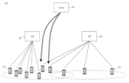
- each terminal 10 communicates with the access point 20 with the strongest radio wave intensity. Therefore, even if the distribution of the terminals 10 is uneven as shown in FIG. 1, it is difficult to optimize the allocation to the access points 20 .
- SSID Service Set Identifier
- Non-Patent Document 1 calculates optimal values for resource allocation by the control node 30 (WiSMA: Strategy Management Architecture for Wireless resource optimization). Then, the control node 30 controls the access point 20 to which the terminal 10 connects based on the calculation result. For example, the control node 30 issues a connection change instruction to the terminal 10 that needs to change the connection destination access point 20 .
- WiSMA only controls logical connection configuration based on MAC addresses. For this reason, for example, there is a problem that it is difficult to control the connection destination for each detailed section in a room.
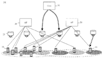
- Non-Patent Document 2 uses the visible light from the light source 25 as a control plane, as shown in FIG. 3, to enable detailed control for each physical position in the room.
- the control node 30 computes the optimal values for resource allocation.
- the control node 30 controls the visible light pattern and color for each light source 25 .
- the visible light includes information for guiding the terminal 10 to the access point 20 to be connected.
- the terminal 10 connects to the destination access point 20 according to the pattern, color, etc. of the received light.
- Non-Patent Document 3 In order to realize the technology of Non-Patent Document 3, it is necessary to add a visible light modulation function to the light source and add visible light reception and demodulation functions to the terminal. In this way, in pinpoint radio resource allocation corresponding to the physical position of a terminal indoors, there is a problem that it is necessary to add functions to facilities and equipment.
- the present invention provides a communication control device, a communication control method, a communication system that does not require addition of functions to facility equipment for allocating communication resources corresponding to physical positions of terminals indoors, and The purpose is to provide a program.
- the communication control device grasps the position of a communication terminal in a specific space from a location metadata source, and performs communication control according to the position.
- the communication control device includes: a receiving unit for receiving location metadata source information from communication terminals within an arbitrary area; a controller that calculates the position of the communication terminal within the arbitrary area based on information from the location metadata source and allocates communication resources according to the position of the communication terminal; Prepare.
- a communication control method includes: receiving location metadata source information from communication terminals in any area; calculating a position of the communication terminal within the arbitrary area based on information from the location metadata source; and allocating communication resources according to the position of the communication terminal.
- This communication control device and this communication control method estimate the position of the communication terminal from the location metadata source.
- Location metadata sources can be obtained from existing sensors, beacon devices, or GPS provided in communication terminals. If the positions of communication terminals can be grasped, radio resource allocation (bandwidth allocation, beamforming, etc.) can be performed based on the distribution of communication terminals. Therefore, the present invention can provide a communication control apparatus and a communication control method that do not require the addition of functions to facility equipment for allocating communication resources corresponding to physical locations of terminals indoors.
- the communication control device is characterized by using a low-layer communication protocol for communication of the location metadata source information.
- location metadata source data can be collected with low load and low latency. In other words, by collecting the location information with low delay, it is possible to grasp the position of the communication terminal in real time and with high accuracy.
- the receiving unit of the communication control device is characterized by receiving the acceleration acquired by the communication terminal together with the information of the location metadata source. It is possible to improve the accuracy of position estimation of the communication terminal and predict the destination.
- a communication system comprises the location metadata source in the arbitrary area and the communication control device.
- the present invention is a program for causing a computer to function as the communication control device.
- the data collection device of the present invention can also be implemented by a computer and a program, and the program can be recorded on a recording medium or provided through a network.
- the present invention can provide a communication control device, a communication control method, a communication system, and a program that do not require addition of functions to facility equipment for allocating communication resources corresponding to the physical location of terminals indoors.
- FIG. 1 is a diagram for explaining a communication system according to the present invention
- FIG. It is a figure explaining operation
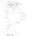
- FIG. 4 is a diagram for explaining the communication system of this embodiment.
- the communication system comprises a location metadata source (26, 27) within the arbitrary area 5 and a communication controller 35.
- the communication control device 35 includes a receiving unit 31 that receives information of the location metadata sources (26, 27) from the communication terminals 10 in the arbitrary area 5, and based on the information of the location metadata sources (26, 27), an arbitrary and a controller 30 that calculates the position of the communication terminal 10 within the area 5 and allocates communication resources according to the position of the communication terminal 10 .
- the positions of the beacon device 27, the sensor 26, and the wireless access point 20 installed within the arbitrary area 5 can be accurately grasped by collecting and analyzing sensing information.
- the sensor 26 detects position, acceleration, temperature, sound, human line of sight, image, wireless information, etc., and sends it to the communication control device 35 as sensing information including information for identifying itself (for example, MAC address). can be sent.
- the communication control device 35 grasping the respective positional relationships within the arbitrary area 5 based on the information obtained from the sensor 26, the beacon device 27, and the access point 20; The current status of the communication terminal 10 in the arbitrary area 5 based on information such as acceleration and beacon information (unique number of the sensor 26 or beacon device 27, signal strength, etc.) collected from the communication terminal 10 via a low-layer communication protocol with low delay Based on the positional relationship between the sensor 26, the beacon device 27, and the access point 20, and the information (eg, MAC address) that identifies the individual communication terminal 10, wired/wireless communication resources (bandwidth, wireless / light beams, etc.) to terminals.
- information eg, MAC address
- the communication terminal 10 sends the information received from the BLE beacon, sensor, etc. to the communication control device 35 .
- the communication terminal 10 may also send sensor information such as acceleration to the communication control device 35 .
- Low layer communication and “low layer communication protocol” mean protocols corresponding to the second layer and the third layer of the OSI reference model.
- the controller 30 collates the positional relationship among the access point 20 , the sensor 26 and the beacon 27 and the real-time position and acceleration information of the communication terminal 10 to estimate the physical position of the communication terminal 10 .
- the controller 30 performs the following control on each wireless access point 20 under its control. (1) Detailed control of the access point 20 to which the communication terminal 10 should connect according to the position (resolution determined by the number of sensors 26 and beacons 27, shape of the arbitrary area 5) (2) Pinpointing the communication terminal 10 Optimal Resource Allocation by Targeted Beamforming (3) Resource Allocation Focused on Communication of a Specific Communication Terminal 10 During Congestion
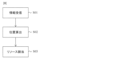
- FIG. 8 is a diagram for explaining a communication control method performed by this communication system.
- This communication control method is Receiving location metadata source information from the communication terminal 10 in the arbitrary area 5 (step S01); Calculating the position of the communication terminal 10 in the arbitrary area 5 based on the information of the location metadata source (step S02), and allocating communication resources according to the position of the communication terminal 10 (step S03).
- the location metadata source may be a GPS or BLE beacon, or may be a group of IoT sensors equipped with a mechanism for grasping location information. In other words, any means that can identify the position of the communication terminal 10 may be used.
- the communication terminal 10 acquires information about its own location from a location metadata source (step S01).
- the communication terminal 10 may also acquire the location information of the location metadata source itself.
- the communication terminal 10 transmits the information to the receiving section 31 of the communication control device 35 (step S01a).
- Information for ascertaining the locations of communication terminals and sensors is transmitted to the communication control device 35 with low load and low delay using a low-layer communication protocol.
- the information received by the receiving unit 31 is transferred to the data collection analysis unit 30a.
- the data collection and analysis unit 30a collects and analyzes information from sensors and communication terminals, and calculates the position (eg, three-dimensional coordinates) of the communication terminal 10 (step S02).
- the calculation result of the data collection and analysis section 30a is transferred to the control section 30b (step S02a).
- the control unit 30b grasps the location of the communication terminal 10 and performs communication resource allocation calculation (step S03).
- the control unit 30b notifies the wireless access point 20 of the calculated communication resource allocation as a control signal (step S04).
- Wireless access point 20 allocates communication resources according to the position of communication terminal 10 according to the control signal (step S05). Allocation of communication resources includes, for example, band allocation, beamforming in wireless communication, and directing an optical axis in visible light communication.
- FIG. 6 the dotted line is the communication route before the communication terminal 11 moves, and the solid line is the communication route after the communication terminal 11 moves.
- the data collection and analysis unit 30a checks the received acceleration data of the communication terminal 11, and determines that the communication terminal has moved when the acceleration exceeds a predetermined threshold. After that, as described with reference to FIGS. 5 and 7, steps S01 to S02a are performed.
- the movement of the communication terminal 11 is not limited to crossing over different areas as shown in FIG. 6, and may be movement within the same area.
- the control unit 30b grasps the location of the communication terminal 10 and performs communication resource allocation calculation (step S03).
- the control unit 30b allocates communication resources in accordance with movement of the communication terminal 10 or change in location. In some cases, the allocation of communication resources may not change.
- the control unit 30b notifies the wireless access point 20 of the calculated communication resource allocation as a control signal (step S04).
- Wireless access point 20 allocates communication resources according to the position of communication terminal 10 according to the control signal (step S05).
- the wireless access point 20 receives a control signal for changing the allocation of communication resources due to movement of the communication terminal 10 or change of location, the wireless access point 20 performs band allocation, beamforming, and change of the optical axis accordingly.
- the wireless access point 20 receives a control signal that does not change the allocation of communication resources even if the communication terminal 10 moves or changes its location, the wireless access point 20 does not perform band allocation, beam forming, or change of the optical axis accordingly.
- this communication system utilizes sensing data collected with low latency to perform highly accurate indoor location and advanced network control (such as pinpoint network resource allocation corresponding to physical location). can be realized. For this reason, this communication system does not add physical additional functions (visible light communication, etc.) to the terminal, and based on real-time terminal position information collected with low load, the position and density of people/terminals. , direction of movement, speed of movement, etc., fine-grained network control (pinpoint beamforming, resource allocation, etc.) can be performed.
- the controller 30 can also be implemented by a computer and a program, and the program can be recorded on a recording medium or provided through a network.
- FIG. 9 shows a block diagram of system 100 .
- System 100 includes computer 105 connected to network 135 .
- the network 135 is a data communication network.
- Network 135 may be a private network or a public network, and may be (a) a personal area network covering, for example, a room; (b) a local area network covering, for example, a building; (d) a metropolitan area network covering, for example, a city; (e) a wide area network covering, for example, a connected area across city, regional, or national boundaries; Any or all of an area network, or (f) the Internet. Communication is by electronic and optical signals through network 135 .
- Computer 105 includes a processor 110 and memory 115 coupled to processor 110 . Although computer 105 is represented herein as a stand-alone device, it is not so limited, but rather may be connected to other devices not shown in a distributed processing system.
- the processor 110 is an electronic device made up of logic circuits that respond to and execute instructions.
- the memory 115 is a tangible computer-readable storage medium in which a computer program is encoded.
- memory 115 stores data and instructions, or program code, readable and executable by processor 110 to control its operation.
- Memory 115 may be implemented in random access memory (RAM), hard drive, read only memory (ROM), or a combination thereof.
- One of the components of memory 115 is program module 120 .
- Program modules 120 contain instructions for controlling processor 110 to perform the processes described herein. Although operations are described herein as being performed by computer 105 or a method or process or its subprocesses, those operations are actually performed by processor 110 .
- module is used herein to refer to a functional operation that can be embodied either as a standalone component or as an integrated composition of multiple subcomponents. Accordingly, program module 120 may be implemented as a single module or as multiple modules working in cooperation with each other. Further, although program modules 120 are described herein as being installed in memory 115 and thus being implemented in software, program modules 120 may be implemented in hardware (eg, electronic circuitry), firmware, software, or a combination thereof. Either of them can be realized.
- Storage device 140 is a tangible computer-readable storage medium that stores program modules 120 .
- Examples of storage devices 140 include compact discs, magnetic tapes, read-only memory, optical storage media, hard drives or memory units consisting of multiple parallel hard drives, and universal serial bus (USB) flash drives. be done.
- storage device 140 may be random access memory or other type of electronic storage device located in a remote storage system, not shown, and connected to computer 105 via network 135 .
- System 100 further includes data source 150 A and data source 150 B, collectively referred to herein as data source 150 and communicatively coupled to network 135 .
- data sources 150 may include any number of data sources, one or more.
- Data sources 150 contain unstructured data and can include social media.
- System 100 further includes user device 130 operated by user 101 and connected to computer 105 via network 135 .
- User device 130 includes input devices such as a keyboard or voice recognition subsystem for allowing user 101 to communicate information and command selections to processor 110 .
- User device 130 further includes an output device such as a display or printer or speech synthesizer.
- a cursor control such as a mouse, trackball, or touch-sensitive screen, allows user 101 to manipulate a cursor on the display to convey further information and command selections to processor 110 .
- the processor 110 outputs results 122 of execution of the program modules 120 to the user device 130 .
- processor 110 may provide output to storage 125, such as a database or memory, or via network 135 to a remote device not shown.
- the program module 120 may be a program that performs the flowchart of FIG. System 100 may operate as controller 30 .
- various inventions can be formed by appropriately combining a plurality of constituent elements disclosed in the above embodiments. For example, some components may be omitted from all components shown in the embodiments. Furthermore, constituent elements across different embodiments may be combined as appropriate.
Landscapes
- Engineering & Computer Science (AREA)
- Computer Networks & Wireless Communication (AREA)
- Signal Processing (AREA)
- Mobile Radio Communication Systems (AREA)
Abstract
Description
任意エリア内の通信端末から場所メタデータ源の情報を受信する受信部と、
前記場所メタデータ源の情報に基づいて、前記任意エリア内における前記通信端末の位置を算出し、前記通信端末の位置に応じて通信リソースを割り当てるコントローラと、
を備える。
任意エリア内の通信端末から場所メタデータ源の情報を受信すること、
前記場所メタデータ源の情報に基づいて、前記任意エリア内における前記通信端末の位置を算出すること、及び
前記通信端末の位置に応じて通信リソースを割り当てること
を行う。
図4は、本実施形態の通信システムを説明する図である。本通信システムは、任意エリア5内の場所メタデータ源(26、27)と、通信制御装置35と、を備える。通信制御装置35は、任意エリア5内の通信端末10から場所メタデータ源(26、27)の情報を受信する受信部31と、場所メタデータ源(26、27)の情報に基づいて、任意エリア5内における通信端末10の位置を算出し、通信端末10の位置に応じて通信リソースを割り当てるコントローラ30と、を備える。
センサ26、ビーコン装置27、及びアクセスポイント20から得られた情報を基に任意エリア5内におけるそれぞれの位置関係を把握すること、
通信端末10から低レイヤ通信プロトコルを介して低遅延に収集した加速度及びビーコン情報(センサ26やビーコン装置27の固有番号、信号強度等)の情報を基に任意エリア5内における通信端末10の現在位置を把握すること、及び
センサ26、ビーコン装置27、及びアクセスポイント20の位置関係、通信端末10の個体を識別する情報(例:MACアドレス)を基に、有線/無線通信リソース(帯域、無線/光ビーム等)の端末への割り当て行う。
(1)位置(センサ26及びビーコン27の数で定まる解像度、任意エリア5の形状)に応じた、通信端末10が接続すべきアクセスポイント20のきめ細かな制御
(2)通信端末10をピンポイントに狙ったビームフォーミングによる最適なリソース割り当て
(3)混雑時における、特定の通信端末10の通信にフォーカスしたリソース割り当て
任意エリア5内の通信端末10から場所メタデータ源の情報を受信すること(ステップS01)、
場所メタデータ源の情報に基づいて、任意エリア5内における通信端末10の位置を算出すること(ステップS02)、及び
通信端末10の位置に応じて通信リソースを割り当てること(ステップS03)を行う。
このため、本通信システムは、端末に物理的な追加機能(可視光通信等)を加えることなく、かつ、低負荷に収集したリアルタイムの端末位置情報をもとに、人/端末の位置、密度、移動方向、移動速度等に応じたきめこまやかなネットワーク制御(ピンポイントなビームフォーミング、リソース割り当てなど)を行うことができる。
コントローラ30はコンピュータとプログラムによっても実現でき、プログラムを記録媒体に記録することも、ネットワークを通して提供することも可能である。
図9は、システム100のブロック図を示している。システム100は、ネットワーク135へと接続されたコンピュータ105を含む。
なお、この発明は上記実施形態に限定されるものではなく、この発明の要旨を逸脱しない範囲で種々変形して実施可能である。要するにこの発明は、上位実施形態そのままに限定されるものではなく、実施段階ではその要旨を逸脱しない範囲で構成要素を変形して具体化できる。
10:通信端末
20:アクセスポイント
25:光源
26:センサ
27:ビーコン装置
30:コントローラ
30a:データ収集分析部
30b:コントロール部
31:受信部
35:通信制御装置
100:システム
101:ユーザ
105:コンピュータ
110:プロセッサ
115:メモリ
120:プログラムモジュール
122:結果
125:記憶装置
130:ユーザデバイス
135:ネットワーク
140:記憶装置
150:データソース
Claims (8)
- 任意エリア内の通信端末から場所メタデータ源の情報を受信する受信部と、
前記場所メタデータ源の情報に基づいて、前記任意エリア内における前記通信端末の位置を算出し、前記通信端末の位置に応じて通信リソースを割り当てるコントローラと、
を備える通信制御装置。 - 前記場所メタデータ源の情報の通信には低レイヤ通信プロトコルを利用することを特徴とする請求項1に記載の通信制御装置。
- 前記受信部は、前記場所メタデータ源の情報とともに前記通信端末が取得した加速度も受信することを特徴とする請求項1又は2に記載の通信制御装置。
- 任意エリア内の通信端末から場所メタデータ源の情報を受信すること、
前記場所メタデータ源の情報に基づいて、前記任意エリア内における前記通信端末の位置を算出すること、及び
前記通信端末の位置に応じて通信リソースを割り当てること
を行う通信制御方法。 - 前記場所メタデータ源の情報の通信には低レイヤ通信プロトコルを利用することを特徴とする請求項4に記載の通信制御方法。
- 前記場所メタデータ源の情報とともに前記通信端末が取得した加速度も受信することを特徴とする請求項4又は5に記載の通信制御方法。
- 前記任意エリア内の前記場所メタデータ源と、
請求項1から3のいずれかに記載の通信制御装置と、
を備える通信システム。 - 請求項1から3のいずれかに記載の通信制御装置としてコンピュータを機能させるためのプログラム。
Priority Applications (3)
| Application Number | Priority Date | Filing Date | Title |
|---|---|---|---|
| PCT/JP2021/028633 WO2023012869A1 (ja) | 2021-08-02 | 2021-08-02 | 通信制御装置、通信制御方法、通信システム、及びプログラム |
| US18/579,652 US20240334387A1 (en) | 2021-08-02 | 2021-08-02 | Communication control device, communication control method, communication system, and program |
| JP2023539394A JP7641472B2 (ja) | 2021-08-02 | 2021-08-02 | 通信制御装置、通信制御方法、通信システム、及びプログラム |
Applications Claiming Priority (1)
| Application Number | Priority Date | Filing Date | Title |
|---|---|---|---|
| PCT/JP2021/028633 WO2023012869A1 (ja) | 2021-08-02 | 2021-08-02 | 通信制御装置、通信制御方法、通信システム、及びプログラム |
Publications (1)
| Publication Number | Publication Date |
|---|---|
| WO2023012869A1 true WO2023012869A1 (ja) | 2023-02-09 |
Family
ID=85154350
Family Applications (1)
| Application Number | Title | Priority Date | Filing Date |
|---|---|---|---|
| PCT/JP2021/028633 Ceased WO2023012869A1 (ja) | 2021-08-02 | 2021-08-02 | 通信制御装置、通信制御方法、通信システム、及びプログラム |
Country Status (3)
| Country | Link |
|---|---|
| US (1) | US20240334387A1 (ja) |
| JP (1) | JP7641472B2 (ja) |
| WO (1) | WO2023012869A1 (ja) |
Citations (2)
| Publication number | Priority date | Publication date | Assignee | Title |
|---|---|---|---|---|
| JP2017183780A (ja) * | 2016-03-28 | 2017-10-05 | 株式会社ゼンリンデータコム | 端末、情報処理システム、情報処理方法、及びプログラム |
| JP2019537873A (ja) * | 2016-10-21 | 2019-12-26 | クアルコム,インコーポレイテッド | ビームフォーミング手順において使用するためのミリメートル波長ネットワークマップ |
Family Cites Families (8)
| Publication number | Priority date | Publication date | Assignee | Title |
|---|---|---|---|---|
| JP2544855B2 (ja) * | 1991-09-25 | 1996-10-16 | 住友電気工業株式会社 | 車両誘導装置 |
| JP2000268288A (ja) * | 1999-03-19 | 2000-09-29 | Nippon Telegr & Teleph Corp <Ntt> | 移動車両位置追跡制御システム |
| JP2003208381A (ja) * | 2001-04-20 | 2003-07-25 | Nippon Telegr & Teleph Corp <Ntt> | トークン型コンテンツ提供システム及びトークン型コンテンツ提供方法及び携帯型利用者端末 |
| WO2010026799A1 (ja) * | 2008-09-02 | 2010-03-11 | 日本電気株式会社 | コンテンツダウンロードシステム、エージェント、及びコンテンツダウンロード方法 |
| JP5971323B2 (ja) * | 2010-01-06 | 2016-08-17 | 日本電気株式会社 | 通信装置、通信システムおよび通信方法 |
| JP5623143B2 (ja) * | 2010-06-04 | 2014-11-12 | 京セラ株式会社 | 無線端末装置及び制御方法 |
| EP3026596A1 (en) * | 2014-11-26 | 2016-06-01 | Thomson Licensing | System for identifying a location of a mobile tag reader |
| JP2021005832A (ja) * | 2019-06-27 | 2021-01-14 | 矢崎総業株式会社 | 車両通信システム |
-
2021
- 2021-08-02 US US18/579,652 patent/US20240334387A1/en active Pending
- 2021-08-02 WO PCT/JP2021/028633 patent/WO2023012869A1/ja not_active Ceased
- 2021-08-02 JP JP2023539394A patent/JP7641472B2/ja active Active
Patent Citations (2)
| Publication number | Priority date | Publication date | Assignee | Title |
|---|---|---|---|---|
| JP2017183780A (ja) * | 2016-03-28 | 2017-10-05 | 株式会社ゼンリンデータコム | 端末、情報処理システム、情報処理方法、及びプログラム |
| JP2019537873A (ja) * | 2016-10-21 | 2019-12-26 | クアルコム,インコーポレイテッド | ビームフォーミング手順において使用するためのミリメートル波長ネットワークマップ |
Also Published As
| Publication number | Publication date |
|---|---|
| JP7641472B2 (ja) | 2025-03-07 |
| US20240334387A1 (en) | 2024-10-03 |
| JPWO2023012869A1 (ja) | 2023-02-09 |
Similar Documents
| Publication | Publication Date | Title |
|---|---|---|
| KR101616486B1 (ko) | 모바일 디바이스 포지셔닝 | |
| JP5657798B2 (ja) | 構造物内の移動端末の位置推定の使用に関する方法および装置 | |
| CN110213714B (zh) | 终端定位的方法及装置 | |
| US8971919B2 (en) | Fast generation of radio coverage map of access points in an indoor environment | |
| CN108828523A (zh) | 振动波定位方法、装置、系统和计算机存储介质 | |
| JP2019021975A (ja) | 制御装置および飛行体制御方法 | |
| CN116074199B (zh) | 6g空天地场景细粒度按需服务方法 | |
| WO2024001077A1 (zh) | 一种巡检单元的巡检控制方法、装置及电子设备 | |
| CN114339912A (zh) | 网络连接方法、装置、设备和存储介质 | |
| US9037131B2 (en) | Efficient generation of radio coverage map of access points in an indoor environment | |
| CN110770594B (zh) | 客运车辆地理定位 | |
| JP7641472B2 (ja) | 通信制御装置、通信制御方法、通信システム、及びプログラム | |
| CN112649827A (zh) | 用于轨道交通室内外的无缝切换实时导航方法及设备 | |
| WO2014097348A1 (ja) | 情報処理装置の制御方法、制御プログラム、情報処理装置 | |
| US20230319506A1 (en) | Active information for user devices for improved service delivery | |
| JP7567937B2 (ja) | IoT通信システム、アクセスポイント、センサ装置、IoT通信方法およびプログラム | |
| JP7122269B2 (ja) | 無線構成の評価方法及び無線設計支援シミュレータ | |
| TWI721685B (zh) | 用於預測行動網路的客訴熱區的系統和方法 | |
| CN112235430B (zh) | 阻碍收集有效信息的方法和装置、电子设备 | |
| CN114676491A (zh) | 一种铁路通信铁塔设计高度快速优化确定方法及系统 | |
| WO2022201682A1 (ja) | 位置検知システム、位置検知方法及びプログラム | |
| CN116248560B (zh) | 目标信息的生成方法、装置及存储介质 | |
| CN115988412B (zh) | 基于基站位置的5g切片接入方法、装置、设备和介质 | |
| US20250220623A1 (en) | Seamless roaming in ultra-wideband | |
| WO2026028389A1 (ja) | 無線通信装置及び位置推定方法 |
Legal Events
| Date | Code | Title | Description |
|---|---|---|---|
| 121 | Ep: the epo has been informed by wipo that ep was designated in this application |
Ref document number: 21952700 Country of ref document: EP Kind code of ref document: A1 |
|
| WWE | Wipo information: entry into national phase |
Ref document number: 2023539394 Country of ref document: JP |
|
| WWE | Wipo information: entry into national phase |
Ref document number: 18579652 Country of ref document: US |
|
| NENP | Non-entry into the national phase |
Ref country code: DE |
|
| 122 | Ep: pct application non-entry in european phase |
Ref document number: 21952700 Country of ref document: EP Kind code of ref document: A1 |