WO2023008428A1 - Cell image analysis method - Google Patents
Cell image analysis method Download PDFInfo
- Publication number
- WO2023008428A1 WO2023008428A1 PCT/JP2022/028777 JP2022028777W WO2023008428A1 WO 2023008428 A1 WO2023008428 A1 WO 2023008428A1 JP 2022028777 W JP2022028777 W JP 2022028777W WO 2023008428 A1 WO2023008428 A1 WO 2023008428A1
- Authority
- WO
- WIPO (PCT)
- Prior art keywords
- cell
- cell image
- image
- value
- probability
- Prior art date
Links
- 238000003703 image analysis method Methods 0.000 title claims abstract description 43
- 238000004458 analytical method Methods 0.000 claims abstract description 43
- 210000004027 cell Anatomy 0.000 claims description 705
- 239000011248 coating agent Substances 0.000 claims description 44
- 238000010191 image analysis Methods 0.000 claims description 38
- 238000003384 imaging method Methods 0.000 claims description 38
- 230000002159 abnormal effect Effects 0.000 claims description 34
- 238000000034 method Methods 0.000 claims description 29
- 210000004748 cultured cell Anatomy 0.000 claims description 11
- 238000010586 diagram Methods 0.000 description 16
- 230000012447 hatching Effects 0.000 description 9
- 238000013527 convolutional neural network Methods 0.000 description 3
- 238000012258 culturing Methods 0.000 description 3
- 230000004069 differentiation Effects 0.000 description 3
- 230000000694 effects Effects 0.000 description 3
- 239000003550 marker Substances 0.000 description 3
- 230000004048 modification Effects 0.000 description 2
- 238000012986 modification Methods 0.000 description 2
- 238000004113 cell culture Methods 0.000 description 1
- 210000001671 embryonic stem cell Anatomy 0.000 description 1
- 230000006870 function Effects 0.000 description 1
- 238000011534 incubation Methods 0.000 description 1
- 210000004263 induced pluripotent stem cell Anatomy 0.000 description 1
- 238000002372 labelling Methods 0.000 description 1
- 239000004973 liquid crystal related substance Substances 0.000 description 1
- 102000004169 proteins and genes Human genes 0.000 description 1
- 108090000623 proteins and genes Proteins 0.000 description 1
- 230000011218 segmentation Effects 0.000 description 1
- 239000007787 solid Substances 0.000 description 1
Images


Classifications
-
- C—CHEMISTRY; METALLURGY
- C12—BIOCHEMISTRY; BEER; SPIRITS; WINE; VINEGAR; MICROBIOLOGY; ENZYMOLOGY; MUTATION OR GENETIC ENGINEERING
- C12M—APPARATUS FOR ENZYMOLOGY OR MICROBIOLOGY; APPARATUS FOR CULTURING MICROORGANISMS FOR PRODUCING BIOMASS, FOR GROWING CELLS OR FOR OBTAINING FERMENTATION OR METABOLIC PRODUCTS, i.e. BIOREACTORS OR FERMENTERS
- C12M1/00—Apparatus for enzymology or microbiology
- C12M1/34—Measuring or testing with condition measuring or sensing means, e.g. colony counters
-
- C—CHEMISTRY; METALLURGY
- C12—BIOCHEMISTRY; BEER; SPIRITS; WINE; VINEGAR; MICROBIOLOGY; ENZYMOLOGY; MUTATION OR GENETIC ENGINEERING
- C12Q—MEASURING OR TESTING PROCESSES INVOLVING ENZYMES, NUCLEIC ACIDS OR MICROORGANISMS; COMPOSITIONS OR TEST PAPERS THEREFOR; PROCESSES OF PREPARING SUCH COMPOSITIONS; CONDITION-RESPONSIVE CONTROL IN MICROBIOLOGICAL OR ENZYMOLOGICAL PROCESSES
- C12Q1/00—Measuring or testing processes involving enzymes, nucleic acids or microorganisms; Compositions therefor; Processes of preparing such compositions
- C12Q1/02—Measuring or testing processes involving enzymes, nucleic acids or microorganisms; Compositions therefor; Processes of preparing such compositions involving viable microorganisms
-
- G—PHYSICS
- G06—COMPUTING; CALCULATING OR COUNTING
- G06T—IMAGE DATA PROCESSING OR GENERATION, IN GENERAL
- G06T7/00—Image analysis
Definitions
- This invention relates to a cell image analysis method, and more particularly to a cell analysis method for analyzing cells using a learned model.
- International Publication No. 2019/171546 discloses a cell image analysis method for analyzing a cell image captured by an imaging device. Specifically, International Publication No. 2019/171546 discloses a configuration for acquiring a cell image by photographing cells cultured in a culture plate with an imaging device such as a microscope. In addition, the cell image analysis method disclosed in International Publication No. 2019/171546 uses the analysis results of the trained model to classify whether the cells appearing in the cell image are normal cells or abnormal cells. . Further, International Publication No. 2019/171546 discloses a configuration for classifying cells by segmentation processing for determining which category each pixel belongs to for each pixel of a cell image.
- the present invention has been made to solve the above problems, and one object of the present invention is to provide a cell image analysis method capable of easily grasping the accuracy of classification of cells reflected in a cell image. is to provide
- a cell image analysis method comprises a step of acquiring a cell image showing cells, and a trained model trained to classify cells into two or more types and a step of inputting a cell image to the cell image, and based on the analysis result of each pixel of the cell image output by the trained model, the cell appearing in the cell image is any of two or more types of classification a step of acquiring an index value representing the accuracy; and a step of displaying the acquired index value.
- the cell image analysis method in the above one aspect based on the analysis result of each pixel of the cell image output by the trained model, the cell image is classified into any of two or more types. and a step of displaying the obtained index value. As a result, an index value representing the accuracy of which of the two or more types of classification the cell in the cell image belongs to is displayed. By checking the index value, the operator can It is possible to easily grasp the accuracy of classification of cells reflected in the cell image. As a result, it is possible to provide a cell image analysis method that makes it possible to easily grasp the accuracy of classification of cells appearing in a cell image.
- FIG. 1 is a schematic diagram showing the overall configuration of a cell image analysis device according to one embodiment;
- FIG. It is a schematic diagram for explaining a cell image.
- FIG. 3 is a schematic diagram for explaining cells cultured in a culture vessel;
- FIG. 4 is a schematic diagram for explaining a method of learning a learning model and a method of analyzing a cell image using a learned model according to one embodiment;
- 7A to 7C are schematic diagrams for explaining differences in cell images due to different imaging conditions;
- FIG. FIG. 4 is a schematic diagram for explaining a configuration in which an image processing unit according to one embodiment generates a probability distribution image;
- 4A to 4C are schematic diagrams for explaining a superimposed cell image generated by a superimposed cell image generating unit according to one embodiment;
- FIG. 4 is a schematic diagram for explaining differences in numerical data of representative values of probability values due to differences in focus of cell images.
- FIG. 10 is a schematic diagram for explaining a configuration for displaying a frequency distribution of probability values when a cell image is in focus;
- FIG. 10 is a schematic diagram for explaining a configuration for displaying a frequency distribution of probability values when a cell image is out of focus;
- FIG. 4 is a schematic diagram for explaining a configuration in which a cell analysis device according to one embodiment displays a superimposed cell image, a representative value of probability values, and a frequency distribution.
- 4A and 4B are schematic diagrams for explaining differences in superimposed cell images due to differences in coating agents of culture vessels for culturing cells.
- FIG. 5 is a schematic diagram for explaining differences in numerical data of representative values of probability values due to differences in coating agents.
- 7A to 7D are schematic diagrams (A) to (D) for explaining differences in superimposed cell images due to differences in the number of days in which cells are cultured.
- FIG. FIG. 4 is a schematic diagram for explaining differences in numerical data of representative values of probability values due to differences in the number of days of cell culture. 4 is a flow chart for explaining a process of displaying an index value, a frequency distribution, and a superimposed cell image by a cell image analysis device according to one embodiment; 4 is a flow chart for explaining processing for generating a learned model by the cell image analysis device according to one embodiment. 4 is a flow chart for classifying cell images by the cell image analysis device according to one embodiment.
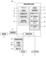
- the cell image analysis apparatus 100 includes an image acquisition unit 1, a processor 2, a storage unit 3, a display unit 4, and an input reception unit 5, as shown in FIG.
- the image acquisition unit 1 is configured to acquire a cell image 10.
- the cell image 10 is an image showing cells 90 (see FIG. 2).
- the cell image 10 is an image of cultured cells 90 cultured in a culture solution 81 (see FIG. 3) filled in a culture vessel 80 (see FIG. 3).
- the image acquisition unit 1 is configured to acquire the cell image 10 from a device for capturing the cell image 10, such as a microscope 8 to which an imaging device is attached.
- Image acquisition unit 1 includes, for example, an input/output interface.
- the processor 2 is configured to analyze the acquired cell image 10.
- the processor 2 includes a CPU (Central Processing Unit), a ROM (Read Only Memory), a RAM (Random Access Memory), a GPU (Graphics Processing Unit), or an FPGA (Field-Programmable Gate Array) configured for image processing. contains.
- the processor 2 including a CPU as hardware includes, as functional blocks of software (programs), a control unit 2a, an image analysis unit 2b, an image processing unit 2c, and a superimposed cell image generation unit 2d. .
- the processor 2 functions as a control unit 2a, an image analysis unit 2b, an image processing unit 2c, and a superimposed cell image generation unit 2d.
- the control unit 2a, the image analysis unit 2b, the image processing unit 2c, and the superimposed cell image generation unit 2d may be individually configured by hardware by providing a dedicated processor (processing circuit).
- the control unit 2a is configured to control the cell image analysis device 100.
- the control unit 2a is also configured to acquire an index value 20 representing the degree of certainty as to which of two or more types the cell 90 appearing in the cell image 10 belongs to.
- the control unit 2a is configured to obtain, as the index value 20, a representative value 20a of the probability values 21 obtained based on the probability values 21 (see FIG. 4) output by the trained model 6.
- the index value 20 is a real number representing the degree of certainty of which of two or more types the cell 90 captured in the cell image 10 belongs to.
- the index value 20 is a numerical value in the range of 0-100.
- the control unit 2a outputs one index value 20 for one cell image 10.
- control unit 2a determines whether the cell image 10 is in focus when photographed, whether the coating agent for the culture vessel 80 (see FIG. 3) is appropriate, and the number of days of culture. is appropriate or not, at least one of the index values 20 is acquired.
- the probability value 21 is an estimated value of the classification output by the trained model 6 as an analysis result.
- the learned model 6 outputs a probability value 21 for each pixel of the cell image 10 as an analysis result.
- control unit 2a is configured to perform control to display the superimposed cell image 50 on the display unit 4. Details of the configuration for the control unit 2a to acquire the index value 20 and the details of the superimposed cell image 50 will be described later.
- the image analysis unit 2b classifies the cells 90 (see FIG. 2) into two or more types. Specifically, it is configured to classify the cells 90 appearing in the cell image 10 into two or more types using the trained model 6 that has learned to classify the cells 90 into two or more types.
- the trained model 6 includes a first trained model 6a, a second trained model 6b, and a third trained model 6c that classify for each imaging condition and culture condition, which will be described later. The details of the normal cells, the abnormal cells, the first trained model 6a, the second trained model 6b, and the third trained model 6c will be described later.
- the image processing unit 2c is configured to generate a probability distribution image 12 (see FIG. 6), which will be described later.
- the image processing unit 2 c is also configured to acquire a cell region, which is the region of the cells 90 appearing in the cell image 10 , based on the probability distribution image 12 . Details of the configuration for generating the probability distribution image 12 and the configuration for acquiring the cell region by the image processing unit 2c will be described later.
- the superimposed cell image generation unit 2d is configured to generate a superimposed cell image 50 in which the distribution of the probability values 21 (see FIG. 4) is superimposed on the cell image 10.
- the details of the configuration for generating the superimposed cell image 50 by the superimposed cell image generation unit 2d will be described later.
- the storage unit 3 is configured to store the cell image 10, the first trained model 6a, the second trained model 6b, and the third trained model 6c. Further, the storage unit 3 is configured to store various programs executed by the processor 2 .
- the storage unit 3 includes, for example, a storage device such as an HDD (Hard Disk Drive) or an SSD (Solid State Drive).
- the display unit 4 is configured to display the superimposed cell image 50 generated by the superimposed cell image generation unit 2d, the index value 20, the frequency distribution 22, and the like.
- Display unit 4 includes, for example, a display device such as a liquid crystal monitor.
- the input reception unit 5 is configured to be able to receive operation input by the operator.
- Input reception unit 5 includes an input device such as a mouse and a keyboard.
- a cell image 10 is an image in which a cultured cell 90 is captured.
- the cell image 10 is a microscopic image captured by a microscope 8 to which an imaging device is attached.
- a cell image 10 is an image of a cell 90 having differentiation potential as a cultured cell 90 .
- the cells 90 include iPS cells (induced pluripotent stem cells), ES cells (embryonic stem cells), and the like.
- an undifferentiated cell is a cell which has differentiation ability.
- undifferentiated deviant cells are cells that have started to differentiate into specific cells and do not have differentiation potential. In this embodiment, undifferentiated cells are defined as normal cells. Also, undifferentiated deviant cells are defined as abnormal cells.
- cells 90 are cultured cells cultured in culture solution 81 filled in culture container 80 .
- the cell image 10 is an image including cultured cells 90 cultured in the culture container 80 .
- a coating agent for culturing the cells 90 is applied to the bottom surface 80 a of the culture vessel 80 .
- the coating agent contains proteins and the like necessary for the cells 90 to settle in the culture container 80 .
- the cell image analysis apparatus 100 analyzes the cell image 10 to classify the cells 90 appearing in the cell image 10 into two or more types.
- the cell image analysis apparatus 100 analyzes the cell image 10 using the learned model 6 (see FIG. 1) to determine whether the cell 90 in the cell image 10 is one of two or more types. Determine which category it is.
- the trained model 6 outputs a probability value 21 for each pixel of the cell image 10 by inputting the cell image 10 .
- the probability value 21 is an estimate of the classification.
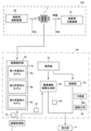
- FIG. 4 is a block diagram showing the flow of image processing according to this embodiment.
- the cell image analysis method is broadly divided into an image analysis method 101 and a trained model 6 (see FIG. 1) generation method 102 .
- a method 102 for generating a trained model 6 generates a trained model 6 by having the learning model 7 learn using the cell image 10 .
- the trained model 6 is generated by learning so as to output a probability value 21 for each pixel of the cell image 10 as an analysis result.
- the method 102 for generating the trained model 6 includes a step 102a of inputting a teacher cell image 30 to the learning model 7 and causing the learning model 7 to output a correct teacher image 31. and Step 102b for learning.
- the trained model 6 is, for example, a convolutional neural network (CNN) shown in FIG. 4, or includes a convolutional neural network as part thereof.
- the learned model 6 generated by learning the learning model 7 is stored in the storage unit 3 ( FIG. 1 ) of the cell image analysis device 100 .
- the trained model 6 determines whether the cell image 10 is in focus, whether the coating agent for the culture vessel 80 is appropriate, and whether the number of days of culture is appropriate. It is created by learning to classify at least one of no.
- a method 102 for generating a trained model 6 includes labeling the teacher cell image 30, which is the cell image 10, and the cell image 10 with at least two types of imaging conditions corresponding to the classification, or A learned model 6 is generated using the correct teacher image 31 with label values associated with at least two corresponding culture conditions.
- the trained model 6 includes a first trained model 6a, a second trained model 6b, and a third trained model 6c.
- the first trained model 6a is based on the cell image 10, and the cells 90 appearing in the cell image 10 are photographed under two or more types of photographing conditions. It is a trained model that has learned to classify whether it is an image. That is, the teacher cell images 30 used to generate the first trained model 6a are the cell images 10 obtained under different imaging conditions.
- the teacher correct image 31 is an image to which each pixel is assigned a different label value depending on the difference in imaging conditions.
- the teacher correct image 31 is an image in which label values of two or more types of imaging conditions are attached to each pixel.
- the imaging condition is whether or not the cell image 10 (teacher cell image 30) is in focus. Therefore, the teacher correct image 31 is an image in which a focused label value and an out-of-focus label value when photographing the cell image 10 are attached to each pixel. That is, the teacher correct image 31 is an image divided into two classes, a focused class and an out-of-focus class.
- the first trained model 6a is generated by having the learning model 7 learn to classify each pixel of the input image into one of two or more types under the shooting conditions. do.
- the second trained model 6b and the third trained model 6c are images in which the cells 90 in the cell image 10 are cultured under two or more types of culture conditions based on the cell image 10. It is a trained model that has learned to classify Specifically, when generating the second trained model 6b and the third trained model 6c, cell images 10 with different culture conditions are used as teacher cell images 30.
- FIG. Also, as the teacher correct image 31, an image is used in which each pixel is labeled with a different label value depending on the culture condition. Specifically, the teacher correct image 31 is an image in which label values of two or more types of culture conditions are attached to each pixel.
- the culture conditions include differences in the coating agents of the culture vessels 80 (see FIG. 3) in which the cells 90 are cultured and differences in the number of days the cells 90 are cultured.
- the teacher correct image 31 to which at least two types of label values regarding the coating agent of the culture container 80 in which the cells 90 are cultured is attached.
- the label value indicating that the coating agent of the culture container 80 in which the cells 90 are cultured is the coating agent A and the label value that is not the coating agent A are assigned to each pixel.
- the correct image 31 for teacher is an image divided into two classes, a class of coating agent A and a class of coating agent B.
- the teacher correct image 31 to which at least two types of label values regarding the number of culture days of the cells 90 are attached is used.
- a label value indicating that the number of culture days of the cell 90 is a predetermined number of days and a label value not The attached image is used as the correct image 31 for teacher.
- the predetermined number of culture days is, for example, 5 days. That is, the teacher correct image 31 is an image divided into two classes, a class with 5 days of culture and a class with a number of days other than 5 days of culture.
- the trained model 6 is suitable for analyzing whether the cell 90 is a normal cell or an abnormal cell by performing two or more types of classification under imaging conditions or culture conditions. It is created by learning to classify whether or not there is. In addition, in the present embodiment, the trained model 6 is created by learning to classify whether cells 90 of the same type are suitable for analysis as to whether they are normal cells or abnormal cells. there is
- the image analysis method 101 classifies which of two or more types the cells 90 appearing in the cell image 10 acquired by the image acquisition unit 1 from the microscope 8 (see FIG. 1) are. It is an image analysis method.
- the image analysis method 101 according to the present embodiment includes the steps of acquiring a cell image 10 showing a cell 90 (see FIG. 2), inputting the cell image 10 to the trained model 6, and a step of acquiring an index value 20 representing the accuracy of which of two or more types the cell 90 shown in the cell image 10 belongs to, based on the analysis result of each pixel of the cell image 10; and displaying the index value 20 obtained. Detailed processing of each step of the image analysis method 101 will be described later.
- the step of acquiring the cell image 10 is performed by the image acquisition unit 1.
- the image acquisition unit 1 acquires a cell image 10 from an image capturing device such as a microscope 8 (see FIG. 1).
- the image acquisition unit 1 also outputs the acquired cell image 10 to the image analysis unit 2b.
- the image acquisition unit 1 also outputs the acquired cell image 10 to the superimposed cell image generation unit 2d.
- the step of analyzing the cell image 10 is performed by the image analysis unit 2b.
- the image analysis unit 2 b acquires the index value 20 by inputting the cell image 10 to the trained model 6 . Specifically, the image analysis unit 2b inputs the cell image 10 to any one of the first trained model 6a, the second trained model 6b, and the third trained model 6c, so that the index value 20 is get. Whether the image analysis unit 2b analyzes using the first trained model 6a, the second trained model 6b, or the third trained model 6c is determined by the control unit 2a.
- the image analysis unit 2b also outputs the acquired index value 20 to the control unit 2a and the superimposed cell image generation unit 2d. Specifically, the image analysis unit 2b outputs the probability value 21 as the index value 20 to the control unit 2a and the superimposed cell image generation unit 2d.
- the control unit 2a determines whether analysis is to be performed using the first trained model 6a, the second trained model 6b, or the third trained model 6c based on the operation input by the operator. judge. Specifically, the control unit 2a analyzes the cell image 10 using the first trained model 6a or the second trained model 6b based on an operation input indicating under which conditions the analysis is to be performed. It is determined whether to perform the analysis or to perform the analysis by the third trained model 6c.
- the control unit 2a acquires the representative value 20a of the probability value 21.
- the control unit 2a obtains one representative value 20a for one cell image 10 based on the probability value 21 obtained for each pixel of the cell image 10.
- FIG. in this embodiment, the control unit 2a is configured to acquire the average value of the probability values 21 as the representative value 20a.
- control unit 2a acquires the frequency distribution 22 of the probability value 21. Further, the control unit 2a causes the display unit 4 to display the acquired representative value 20a and the frequency distribution 22. FIG. The details of the configuration in which the control unit 2a acquires the representative value 20a and the frequency distribution 22 will be described later.
- the superimposed cell image generation unit 2d generates a superimposed cell image 50 based on the cell image 10 and the index value 20. Also, the superimposed cell image generation unit 2 d causes the display unit 4 to display the generated superimposed cell image 50 .
- differences in cell images 10 due to differences in imaging conditions will be described. In the present embodiment, whether the cell image 10 is in focus or not is the difference in the imaging conditions.
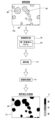
- the cell images 10a to 10c shown in FIGS. 5A to 5C were taken at the same location in the culture vessel 80 (see FIG. 3) with different focal positions.
- the cell image 10a shown in FIG. 5(A) is the cell image 10 in focus. That is, the cell image 10a is an image in which the contrast of the cells 90 is high. In other words, the cell image 10a is an image in which the outline of the cell 90 is clear. Note that an image in focus does not mean that all the cells 90 appearing in the cell image 10 are in focus, but means that the central portion of the cell image 10 is in focus. That is, the focus of the cells 90 captured in the cell image 10a is not uniform, and the degree of defocus increases as the distance from the center of the image increases. That is, there may be cells 90 out of focus in the cell image 10a.
- a cell image 10b shown in FIG. 5(B) is an out-of-focus cell image 10. That is, the cell image 10b shown in FIG. 5B is an image of the cells 90 with low contrast. In other words. The cell image 10b is an image in which the contours of the cells 90 are unclear. Further, the cell image 10b is an image in which the degree of out-of-focus (the degree of defocus) is smaller than that of the cell image 10c shown in FIG. 5(C). Note that “defocus ⁇ 1” marked in FIG. 5(B) indicates that the degree of defocus of the cell image 10b is smaller than that of the cell image 10c shown in FIG. 5(C). . Also, in the cell image 10b shown in FIG.
- the outline of the cell 90 is indicated by a dashed line to indicate that the focus has shifted. Also, in the cell image 10b shown in FIG. 5B, the focus of the cells 90 in the image is not uniform, and the degree of defocus increases as the distance from the center of the image increases.
- a cell image 10c shown in FIG. 5(C) is an out-of-focus cell image 10. That is, the cell image 10c shown in FIG. 5C is an image of the cells 90 with low contrast. In other words, the cell image 10c is an image in which the contours of the cells 90 are unclear. Further, the cell image 10c is an image in which the degree of out-of-focus (the degree of defocus) is larger than that of the cell image 10b. That is, the cell image 10c is an image in which the contours of the cells 90 are less clear. Note that "defocus -2" marked in FIG. 5(C) indicates that the degree of defocus of the cell image 10c is larger than that of the cell image 10b shown in FIG. 5(B).
- the outline of the cell 90 is not shown, indicating that the cell image 10c is out of focus as compared with the cell image 10b. Also, in the cell image 10b shown in FIG. 5B, the focus of the cells 90 in the image is not uniform, and the degree of defocus increases as the distance from the center of the image increases.
- the image analysis unit 2b uses the first trained model 6a to classify which of two or more types the cells 90 appearing in the cell images 10a to 10c belong to.
- the image analysis unit 2b inputs the cell images 10a to 10c to the first trained model 6a, and based on the probability value 21 output from the first trained model 6a, the probability A distribution image 12 is generated.
- the image analysis unit 2b acquires the probability value 21 by inputting the in-focus cell image 10a to the first trained model 6a. That is, in the example shown in FIG. 6, the image analysis unit 2b acquires the probability value 21 for each pixel of the cell image 10a. The image analysis unit 2b also outputs the acquired probability value 21 to the image processing unit 2c. In the example shown in FIG. 6, the image analysis unit 2b acquires, as the probability value 21, the estimated value of the class in which each pixel of the cell image 10 is in focus.
- the image processing unit 2c generates a probability distribution image 12, which is an image showing the distribution of probability values 21.
- the probability distribution image 12 is an image in which probability values 21, which are estimated values of classification, are distributed as pixel values.
- the probability distribution image 12 shown in FIG. 6 is an image representing the distribution of the probability values 21 that are estimated values of the class in which each pixel of the cell image 10 is in focus.
- the difference in the probability value 21 is represented by the difference in hatching.
- the probability value 21 increases in the order of black, dark hatching, and light hatching. Further, as shown in legend 8, one hatching does not indicate one probability value 21, but one hatching is attached to each probability value 21 within a predetermined range.
- the image analysis unit 2b inputs the cell image 10 to the first trained model 6a to obtain the probability value 21 which is the estimated value of the out-of-focus class.
- a probability distribution image 12 showing the distribution of is also obtained.
- the image processing unit 2c also processes the out-of-focus cell image 10b (see FIG. 5) and the cell image 10c (see FIG. 5) in the same manner as the probability distribution image 12 of the in-focus class and the focus obtain the probability distribution image 12 of the class that does not match.
- the superimposed cell image generator 2 d generates a superimposed cell image 50 based on the cell image 10 and the probability distribution image 12 . Specifically, the superimposed cell image generation unit 2d generates the superimposed cell image 50 using the cell image 10 and the probability distribution image 12 acquired for each of at least two types of label values.
- the superimposed cell image generation unit 2d generates a superimposed cell image 50 by superimposing on the cell image 10 labels that can identify differences in the probability values 21.
- the superimposed cell image generation unit 2d superimposes mutually identifiable labels on the probability values 21 of the label values of two or more types of classification.
- the superimposed cell image generation unit 2d superimposes mutually identifiable labels on the probability values 21 of the label values of two or more types of imaging conditions. More specifically, the superimposed cell image generating unit 2d creates labels that are mutually identifiable as the probability value 21 of the label value that is in focus and the probability value 21 of the label value that is out of focus.
- the superimposed cell image generator 2d superimposes a blue label 51 on the probability value 21 of the label value in focus. Also, the superimposed cell image generation unit 2d superimposes a red label 52 on the probability value 21 of the label value that is out of focus.
- blue markers 51 are represented by hatching with the smallest spacing.
- red markers 52 are indicated by hatching with the widest spacing.
- a superimposed cell image 50a shown in FIG. 7(A) is obtained by inputting the cell image 10a (see FIG. 5(A)) in focus to the first trained model 6a. It is an image in which the distribution of the probability value 21 is superimposed.
- a superimposed cell image 50b shown in FIG. 7B is obtained by inputting the out-of-focus cell image 10b (see FIG. 5B) into the first trained model 6a. It is an image in which the distribution of the obtained probability values 21 is superimposed.
- a superimposed cell image 50c shown in FIG. 7C is obtained by inputting the out-of-focus cell image 10c (see FIG. 5C) into the first trained model 6a. It is an image in which the distribution of the obtained probability values 21 is superimposed.
- FIG. 7C is obtained by inputting the out-of-focus cell image 10c (see FIG. 5C) into the first trained model 6a. It is an image in which the distribution of the obtained probability values 21 is superimposed.
- a blue marker 51 is superimposed on the probability value 21 of being in focus.
- a red marker 52 is superimposed on the out-of-focus probability value 21 . Therefore, in the example shown in FIG. 7, in a region where the probability value 21 of being in focus and the probability value 21 of being out of focus are mixed, the gradation mark 53 of blue and red is superimposed. Is displayed. In addition, in the example shown in FIG. 7, as shown in legend 9, the blue-red gradation mark 53 is indicated by hatching at medium intervals.
- the in-focus superimposed cell image 50a there are many regions where blue markers 51 are superimposed, indicating that the probability value of the in-focus is 21. Also, in the superimposed cell image 50c, which is most out of focus, there are many regions superimposed with red markers 52 indicating that the out-of-focus probability value 21 is high. In addition, in the superimposed cell image 50b with a smaller focus shift than in the superimposed cell image 50c, the area where the blue label 51 is superimposed is the largest, followed by the area where the gradation-like label 53 of blue and red is superimposed. many in Moreover, in the superimposed cell image 50b, there is also a region where the red marker 52 is superimposed.
- the control unit 2a is configured to acquire a representative value 20a of the probability values 21.
- the control unit 2 a is configured to acquire numerical data of the representative value 20 a of the probability values 21 . That is, in this embodiment, the control unit 2a is configured to acquire one representative value 20a from the probability values 21 acquired for each pixel of the cell image 10a. Further, in the present embodiment, the control unit 2a is configured to acquire the representative value 20a of the probability values 21 in the cell region as the representative value 20a of the probability values 21.
- control unit 2a acquires the representative value 20a based on the probability value 21 of the label value for one of the two or more types of imaging conditions. Specifically, the control unit 2a acquires the representative value 20a based on the probability value 21 of the label value in focus. That is, the control unit 2a acquires the representative value 20a based on the probability value 21 of the label value suitable for analyzing whether the cell is normal or abnormal.
- the control unit 2a acquires a graph collectively displaying numerical data of a plurality of representative values 20a, as shown in the graph 40a.
- the horizontal axis indicates the defocus for each cell image 10
- the vertical axis indicates the representative value 20a. That is, the horizontal axis "0" in the graph 40a represents the focused cell image 10a. Further, the horizontal axis "-1" in the graph 40a represents the out-of-focus cell image 10b. Further, the horizontal axis "-2" in the graph 40a represents the out-of-focus cell image 10c.
- the representative value 20a becomes smaller as the focus shifts.
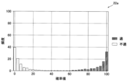
- a frequency distribution 22a shown in FIG. 9 is a frequency distribution obtained based on the probability value 21 of the focused cell image 10a.
- the frequency distribution 22a has the probability value 21 on the horizontal axis and the frequency on the vertical axis. That is, the frequency distribution 22a is a graph of the frequency of the probability values 21 in each pixel of the cell image 10a (see FIG. 5).
- the probability value 21 of the label value of the first type among the two or more types is hatched. That is, in the frequency distribution 22a, the probability values 21 of the focused class are hatched.
- the probability value 21 of the label value of the second type different from the first type among the two or more types is shown in white without hatching. That is, in the frequency distribution 22a, the probability value 21 of the out-of-focus class is shown in white.
- the frequency distribution 22a of the in-focus cell image 10a has a high frequency of pixels with a high probability value 21 in the in-focus class. will be distributed. Further, in the frequency distribution 22a of the in-focus cell image 10a, since the frequency of pixels with low probability values 21 in the out-of-focus class is also high, many pixels are distributed on the left side of the frequency distribution 22a. .
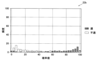
- a frequency distribution 22b shown in FIG. 10 is a frequency distribution acquired based on the probability values 21 of the out-of-focus cell image 10b.
- the frequency distribution 22b has the probability value 21 on the horizontal axis and the frequency on the vertical axis. That is, the frequency distribution 22b is a graph of the frequency of the probability values 21 in each pixel of the cell image 10b (see FIG. 5).
- the probability values 21 of the focused class are hatched, and the probability values 21 of the out-of-focus class are not hatched and are white. is illustrated.
- the frequency distribution 22b of the out-of-focus cell image 10b is compared to the frequency distribution 22a (see FIG. 9) of the in-focus cell image 10a for the in-focus class.
- the frequency of pixels with a high probability value 21 is low, and the frequency of pixels with a low probability value 21 in the in-focus class is high. It is not concentrated on the right side of the distribution 22a, but is distributed almost entirely.
- the frequency distribution 22a of the in-focus cell image 10a has a low frequency of pixels with low probability values 21 in the out-of-focus class, and a low frequency of pixels with low probability values 21 in the out-of-focus class. becomes higher, the frequency distribution 22a is not concentrated on the left side, but is distributed almost entirely. That is, by looking at the shape of the frequency distribution 22, it is possible to easily grasp which of two or more types the cells 90 appearing in the cell image 10 belong to under the imaging conditions. .
- the control unit 2a displays the numerical data of the representative value 20a (see FIG. 4) of the probability values 21 (see FIG. 4) on the display unit 4, and A superimposed cell image 50 in which the distribution of probability values 21 is superimposed on the cell image 10 is displayed.
- the control unit 2a displays the numerical data of the representative values 20a of the probability values 21, the superimposed cell image 50, and the frequency distribution 22 (see FIG. 4) of the probability values 21 on the display unit 4.
- the control unit 2a displays superimposed cell images 50a to 50c as the superimposed cell images 50.
- the control unit 2a displays a graph 40a as the numerical data of the representative value 20a.
- the control unit 2a displays a frequency distribution 22a as the frequency distribution 22.
- a superimposed cell image 50d shown in FIG. 12A is generated based on the cell image 10 and the probability distribution image 12 generated based on the index value 20 obtained by analyzing the cell image 10 with the second trained model 6b. This is an image.
- the superimposed cell image 50d is an image generated based on the cell image 10 obtained by photographing the cells 90 cultured in the culture container 80 to which the coating agent A is applied on the bottom surface 80a of the culture container 80. is.
- the configuration for generating the superimposed cell image 50d uses the first trained model 6a to generate the superimposed cell image 50a to the superimposed cell image 50c, except that the second trained model 6b is used instead of the first trained model 6a. Since the configuration is the same as the configuration to be generated, detailed description is omitted.
- a superimposed cell image 50e shown in FIG. 12B is based on the probability distribution image 12 generated based on the index value 20 obtained by analyzing the cell image 10 with the second trained model 6b and the cell image 10. This is the generated image.
- the superimposed cell image 50e is an image generated based on the cell image 10 obtained by photographing the cells 90 cultured in the culture vessel 80 to which the coating agent B is applied on the bottom surface 80a of the culture vessel 80. is.
- the second trained model 6b is generated by learning that the probability that the coating agent applied to the bottom surface 80a of the culture container 80 is the coating agent A is output as the probability value 21. be done. Therefore, in the superimposed cell image 50d shown in FIG.
- the control unit 2a acquires a representative value 20a for each cell image 10 based on the probability values 21 output by the second trained model 6b. Further, the control unit 2a obtains a graph collectively displaying a plurality of representative values 20a, such as a graph 40b shown in FIG.
- a graph 40b is a graph showing the difference in the representative value 20a depending on the coating agent.
- the horizontal axis is the type of coating agent
- the vertical axis is the representative value 20a.
- the control unit 2a generates the graph 40b except that the probability value 21 output by the second trained model 6b is used instead of the probability value 21 output by the first trained model 6a. Since the configuration is the same as that for generating , detailed description is omitted.
- the representative value 20a of the cell image 10 taken of the cells 90 cultured in the culture vessel 80 coated with the coating agent A is cultured in the culture vessel 80 coated with the coating agent B. It can be seen that it is larger than the representative value 20a of the cell image 10 in which the cell 90 is captured.
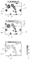
- a superimposed cell image 50f shown in FIG. 14A is an image generated based on the cell image 10 obtained by photographing the cells 90 cultured for 5 days.
- the superimposed cell image 50f is an image generated based on the cell image 10 and the probability distribution image 12 generated based on the index value 20 obtained by analyzing the cell image 10a with the third trained model 6c. is.
- the configuration for generating the superimposed cell image 50f uses the first trained model 6a to generate the superimposed cell image 50a to the superimposed cell image 50c, except that the third trained model 6c is used instead of the first trained model 6a. Since the configuration is the same as the configuration to be generated, detailed description is omitted.
- a superimposed cell image 50g shown in FIG. 14(B) is an image generated based on the cell image 10 obtained by photographing the cells 90 cultured for 4 days.
- a superimposed cell image 50h shown in FIG. 14C is an image generated based on the cell image 10 obtained by photographing the cells 90 cultured for 6 days.
- a superimposed cell image 50i shown in FIG. 14(D) is an image generated based on the cell image 10 obtained by photographing the cells 90 cultured for 7 days.
- the third learned model 6c is generated by learning to output the probability value 21 of whether the number of culture days is 5 or not. Therefore, in the superimposed cell image 50f shown in FIG. 14(A), there are many regions where blue markers 51 are superimposed (regions hatched with the narrowest interval). In addition, in the superimposed cell image 50g shown in FIG. 14B, when compared with the superimposed cell image 50g shown in FIG. area) increases. In addition, as shown in FIGS. 14(C) and 14(D), as the number of culture days increases, an area image on which the red label 52 is superimposed is formed, and the gradation-like label 53 of blue and red is displayed. The overlapped area (medium-spaced hatched area) increases.
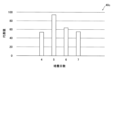
- the control unit 2a acquires the representative value 20a for each cell image 10 based on the probability value 21 output by the third trained model 6c. Further, the control unit 2a obtains a graph collectively displaying a plurality of representative values 20a, such as a graph 40c shown in FIG.
- a graph 40c is a graph showing the difference in the representative value 20a due to the difference in culture days.
- the horizontal axis is the culture days
- the vertical axis is the representative value 20a.
- the control unit 2a generates the graph 40c except that the probability value 21 output by the third trained model 6c is used instead of the probability value 21 output by the first trained model 6a. Since the configuration is the same as that for generating , detailed description is omitted.
- the representative value 20a of the cell image 10 obtained by photographing the cells 90 cultured for 5 days is the highest.
- the representative value 20a of the cell images 10 photographed for the cells 90 cultured for days other than 5 is smaller than the representative value 20a of the cell images 10 photographed for the cells 90 cultured for 5 days.
- the representative value 20a of the cell image 10 obtained by imaging the cell 90 cultured for 4 days and the representative value 20a of the cell image 10 obtained by imaging the cell 90 cultured for 6 days it is found that the number of culture days is 6. It can be seen that the representative value 20a of the cell image 10 obtained by photographing the day's cells 90 is higher.
- the display unit 4 displays a plurality of superimposed cell images 50, numerical data (graph) of representative values 20a, and a frequency distribution 22a. Therefore, based on the plurality of superimposed cell images 50 displayed on the display unit 4, the numerical data (graph) of the representative values 20a, and the frequency distribution 22a, the operator determines that the cells 90 appearing in the cell image 10 are 2 It is possible to determine which of the three or more types it belongs to. That is, the operator can analyze whether the cells 90 appearing in the cell image 10 are normal cells or abnormal cells under two or more types of imaging conditions or two or more types of culture conditions. A suitable classification can be determined.
- the operator can determine whether or not the cell image 10 is suitable for analyzing whether the cell 90 shown in the cell image 10 is a normal cell or an abnormal cell.
- a threshold is set as to whether or not the cell image 10 is suitable for analysis as to whether the cell 90 reflected in the cell image 10 is a normal cell or an abnormal cell. becomes possible. Therefore, in this embodiment, the control unit 2a is configured to determine whether the index value 20 is greater than the threshold. Specifically, the control unit 2a determines whether or not the representative value 20a of the probability values 21 is greater than the threshold set by the operator. It is determined whether the cells are suitable for analysis as to whether they are normal cells or abnormal cells.
- the control unit 2a determines that the cell image 10 is suitable for analyzing whether the cell 90 reflected in the cell image 10 is a normal cell or an abnormal cell. do. Further, for example, when the representative value 20a is less than 50%, the control unit 2a determines that the cell image 10 is not suitable for analyzing whether the cell 90 shown in the cell image 10 is a normal cell or an abnormal cell. judge.
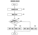
- the image acquisition unit 1 acquires the cell image 10 in which the cell 90 is captured.
- step 201 the image analysis unit 2b inputs the cell image 10 to the trained model 6 that has learned to classify the cells 90 into two or more types.
- the image processing unit 2c acquires the cell area, which is the area of the cell 90 shown in the cell image 10.
- the image processing unit 2c acquires cell regions based on the probability distribution image 12 (see FIG. 6).
- step 203 the control unit 2a classifies the cell 90 appearing in the cell image 10 into any of two or more types based on the analysis result of each pixel of the cell image 10 output by the trained model 6.
- An index value 20 representing the accuracy of whether or not is acquired.
- the control unit 2 a obtains, as the index value 20 , the representative value 20 a of the probability values 21 obtained based on the probability values 21 output by the learned model 6 .
- the control unit 2a determines whether the cell image 10 is in focus, whether the coating agent for the culture container 80 is appropriate, and whether the number of culture days is appropriate. At least one of the index values 20 is acquired.
- the control unit 2a analyzes whether the cell image 10 is a normal cell or an abnormal cell based on the probability value 21. is obtained as the index value 20.
- the control unit 2a acquires the representative value 20a of the probability values 21 in the cell region as the representative value 20a of the probability values 21. Specifically, the control unit 2a acquires the average value of the probability values 21 as the representative value 20a.
- the control unit 2a acquires the frequency distribution 22. Specifically, the control unit 2a acquires the frequency distribution 22 based on the probability values 21 output by the trained model 6. FIG.
- the superimposed cell image generation unit 2d generates the superimposed cell image 50. Specifically, the superimposed cell image generator 2d generates a superimposed cell image 50 based on the cell image 10 and the probability distribution image 12 (see FIG. 6) obtained based on the probability value 21.
- the control unit 2a displays the obtained index value 20.
- the control unit 2a displays a superimposed cell image 50 in which the numerical data of the representative value 20a of the probability values 21 and the distribution of the probability values 21 are superimposed on the cell image 10.
- the control unit 2 a displays the frequency distribution 22 of the probability values 21 together with the numerical data of the representative values 20 a of the probability values 21 and the superimposed cell image 50 .
- step 204 may be performed first.
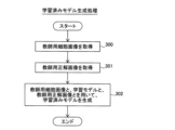
- the image acquisition unit 1 acquires the teacher cell image 30 .
- the teacher cell image 30 is the cell image 10 .
- the image acquisition unit 1 acquires the teacher correct image 31 .
- the correct teacher image 31 is a label value associated with at least two types of imaging conditions corresponding to the classification, or labeled values associated with at least two types of culture conditions corresponding to the classification with respect to the cell image 10. It is a label image.
- the cell images 10 labeled with at least two types of imaging conditions corresponding to the classification are converted into teacher correct images. 31.
- the label values related to the imaging conditions the cell images 10 to which the in-focus label values and the out-of-focus label values when the cell images 10 were photographed are attached to each pixel are used as the teacher. obtained as the correct image 31 for use.
- the out-of-focus label value includes a plurality of label values depending on the degree of the out-of-focus.
- the out-of-focus label values include two label values.
- the image acquisition unit 1 uses the cell images 10 labeled with at least two types of culture conditions corresponding to the classification as a teacher. obtained as the correct image 31 for use. Specifically, the image acquiring unit 1 acquires the cell images 10 to which at least two types of label values regarding the coating agent of the culture vessel 80 in which the cells 90 are cultured are added as the teacher correct image 31 . In this embodiment, the image acquisition unit 1 creates a correct teacher image in which two label values, that is, the label value of the coating agent A and the label value of the coating agent B, are attached to each pixel as label values related to the coating agents. 31 is obtained.
- the image acquisition unit 1 uses the cell images 10 labeled with at least two types of culture conditions corresponding to the classification as a teacher. obtained as the correct image 31 for use. Specifically, the image acquiring unit 1 acquires the cell images 10 to which at least two types of label values regarding the culture days of the cells 90 are attached as the teacher correct images 31 . In the present embodiment, the image acquisition unit 1 creates a correct teacher image in which a label value indicating the number of culture days is 5 and a label value indicating the number of culture days other than 5 are attached to each pixel as label values related to the number of culture days. 31 is obtained.
- step 302 the image processing unit 2c attaches label values relating to at least two imaging conditions corresponding to the classification to the teacher cell image 30, which is the cell image 10, and the cell image 10, or A learned model 6 is created using the teacher correct image 31 to which the label values for at least two corresponding culture conditions are attached.
- the image processing unit 2c attaches two types of label values indicating whether or not the cell image 10 is in focus as the label values relating to the imaging conditions, or Using the teacher correct image 31 with at least two types of label values associated with either the coating agent of the culture container 80 in which the cells 90 are cultured or the number of culture days as the label values regarding the culture conditions, the learned model 6 to create After that, the process ends.
- the control unit 2a acquires the index value 20.
- the control unit 2a acquires the index value 20 acquired by the image analysis unit 2b using the cell image 10 and the learned model 6. FIG.
- the control unit 2a acquires a threshold value. Specifically, the controller 2 a acquires a threshold value preset by the operator and stored in the storage unit 3 .
- the control unit 2a determines whether the index value 20 is greater than the threshold. That is, the control unit 2a determines whether the index value 20 is greater than the threshold for each cell image 10. FIG. If the index value 20 is greater than the threshold, the process proceeds to step 403; If the index value 20 is less than the threshold, processing proceeds to step 404 .
- control unit 2a classifies the cell images 10 into images suitable for analyzing whether the cells 90 are normal cells or abnormal cells. Further, the control unit 2a stores in the storage unit 3 the cell images 10 classified into images suitable for analyzing whether the cells 90 are normal cells or abnormal cells. After that, the process ends.
- step 404 the control unit 2a converts the cell image 10 to an image not suitable for analysis as to whether the cell 90 is a normal cell or an abnormal cell. Classify. In this case, the control unit 2a does not store the cell image 10 in the storage unit 3. FIG. After that, the process ends.
- the cell image analysis method includes the step of acquiring the cell image 10 showing the cell 90, and the trained model 6 trained to classify the cell 90 into two or more types. Based on the step of inputting the cell image 10 and the analysis result of each pixel of the cell image 10 output by the trained model 6, the cell 90 reflected in the cell image 10 is any of two or more types. and a step of displaying the obtained index value 20 .
- the index value 20 representing the accuracy of which of the two or more types of classification the cell 90 shown in the cell image 10 belongs to is displayed, so that the operator can confirm the index value 20.
- the accuracy of the classification of the cells 90 shown in the cell image 10 can be easily grasped.
- the trained model 6 is trained to output the probability value 21, which is the estimated value of the classification, as the analysis result, and in the step of acquiring the index value 20, A representative value 20 a of the probability values 21 obtained based on the probability values 21 output by the trained model 6 is obtained as the index value 20 .
- the accuracy of the classification of the cells 90 appearing in the cell image 10 can be easily determined for each cell image 10 by the representative value 20a of the probability value 21. can grasp.
- the cell image 10 is an image including the cultured cells 90 cultured in the culture container 80, and the trained model 6 is in focus when the cell image 10 is taken. whether the culture container 80 has an appropriate coating agent, and whether the number of culture days is appropriate, and is created by learning to classify at least one of them,
- the step of acquiring the index value 20 whether the cell image 10 is focused, whether the coating agent for the culture container 80 is appropriate, and whether the number of culture days is appropriate At least one of the index values 20 is obtained. Accordingly, by checking the index value 20, the operator can check whether the cell image 10 is in focus, whether the coating agent for the culture container 80 is appropriate, and whether the number of culture days is is appropriate or not.
- the trained model 6 is created by learning to classify whether the cell 90 is suitable for analysis as to whether it is a normal cell or an abnormal cell.
- the probability that the cell image 10 is suitable for analyzing whether the cell 90 reflected in the cell image 10 is a normal cell or an abnormal cell is determined based on the probability value 21.
- the represented value is obtained as the index value 20 .
- an index value 20 representing the degree of suitability of the cell image 10 for analyzing whether the cell 90 shown in the cell image 10 is a normal cell or an abnormal cell is displayed.
- the trained model 6 learns to classify whether the cells 90 of the same type are suitable for analysis as to whether they are normal cells or abnormal cells. It is created by As a result, by analyzing the cell image 10 using the trained model 6, it is possible to classify images suitable for analysis as to whether the cell 90 of the same type is a normal cell or an abnormal cell. .
- the present embodiment further includes the step of acquiring the cell area, which is the area of the cell 90 shown in the cell image 10, and in the step of acquiring the representative value 20a of the probability values 21, As the representative value 20a, the representative value 20a of the probability values 21 in the cell area is obtained.
- the representative value 20a As the representative value 20a, the representative value 20a of the probability values 21 in the cell area is obtained.
- the numerical data of the representative values 20a of the probability values 21 and the distribution of the probability values 21 are superimposed on the cell image 10.
- a superimposed cell image 50 is displayed.
- the representative value 20a of the probability values 21 is displayed, so that the accuracy of classification of the cells 90 appearing in the cell image 10 can be easily grasped for each cell image 10 from the numerical data of the representative value 20a of the probability values 21. be able to.
- the superimposed cell image 50 is displayed, the accuracy of classification of each of the cells 90 appearing in the cell image 10 can be grasped from the superimposed cell image 50 .
- the numerical data of the representative value 20a of the probability values 21 and the superimposed cell image 50 together with the frequency distribution of the probability values 21 22 is displayed. Accordingly, by confirming the frequency distribution 22 together with the numerical data of the representative value 20a of the probability values 21 and the superimposed cell image 50, the accuracy of the classification of the cells 90 reflected in the cell image 10 can be multifaceted for each cell image 10. can be grasped.
- the average value of the probability values 21 is acquired as the representative value 20a.
- the representative value 20a is the value of the first type of classification.
- the cell 90 appearing in the cell image 10 as a whole are the cell images 10 classified as the second type classification different from the first type classification, a part of the probability of the cell image 10 Due to the value 21, the cell 90 appearing in the cell image 10 is classified as being the first type of two or more types. Therefore, as described above, by obtaining the average value of the probability values 21 as the representative value 20a, when classifying the cell image 10 by classifying the cell 90 appearing in the cell image 10, a part of the cell image 10 Due to the probability value 21 of , it is possible to suppress the cell image 10 from being classified as the first type of two or more types. As a result, by classifying the cells 90 appearing in the cell image 10 , it is possible to suppress a decrease in classification accuracy when classifying the cell image 10 .
- the teacher cell image 30, which is the cell image 10, and the cell image 10 are labeled with at least two types of imaging conditions corresponding to the classification, or It further comprises a step of creating a trained model 6 using the correct teacher image 31 labeled with at least two types of culture conditions corresponding to the classification.
- the cell image 10 can be obtained by , it is possible to generate a trained model 6 that can be used to classify which one of two or more types of shooting conditions an image was shot under.
- the cell image 10 can be obtained by using the cell image 10 and the cells 90 shown in the cell image 10 in two or more types of culture conditions. It is possible to generate a trained model 6 that can be used to classify whether an image shows cells 90 cultured under any of the conditions.
- the step of creating the learned model 6 as label values relating to imaging conditions, two types of label values indicating whether or not the cell image 10 is in focus when photographed are used. or at least two types of label values for either the coating agent of the culture vessel 80 for culturing the cells 90 or the number of days of culture as the label values for the culture conditions. to create a trained model 6.
- a trained model 6 can be generated that can be used to classify images into one or more types of classifications.
- this embodiment further includes the step of determining whether the index value 20 is greater than the threshold.
- the cell image 10 with the index value 20 larger than the threshold can be classified as an image suitable for analyzing whether the cell 90 appearing in the cell image 10 is a normal cell or an abnormal cell.
- the cell image 10 with the index value 20 equal to or less than the threshold can be classified as an image that is not suitable for analysis as to whether the cell 90 reflected in the cell image 10 is a normal cell or an abnormal cell. Therefore, when analyzing whether the cell 90 reflected in the cell image 10 is a normal cell or an abnormal cell using a plurality of cell images 10, it is possible to determine whether the cell 90 reflected in the cell image 10 is a normal cell or an abnormal cell. Analysis can be performed using only the cell image 10 suitable for analysis of whether or not it is a cell. As a result, it is possible to prevent a decrease in accuracy in analyzing whether the cells 90 appearing in the cell image 10 are normal cells or abnormal cells.
- control unit 2a acquires the average value of the probability values 21 as the representative value 20a
- the control unit 2a may be configured to acquire one of the median, maximum, minimum, and mode values of the probability values 21 as the representative value 20a.
- the trained model 6 learns to classify whether or not it is in focus, whether the coating agent of the culture vessel 80 is appropriate, and whether the cell
- the trained model 6 may be created by learning based on shooting conditions other than whether or not the camera is in focus.
- the learned model 6 may be created by learning to classify whether or not the type of photographing device is appropriate as the photographing condition.
- the learned model 6 may be created by learning classification based on culture conditions other than whether the coating agent of the culture vessel 80 is appropriate or whether the number of days of culture is appropriate.
- the trained model 6 may be created by learning to classify whether the type of incubation device is appropriate. Any imaging conditions and culture conditions classified by the trained model 6 may be used.
- control unit 2a obtains the representative value 20a of the probability values 21 in the cell region
- control unit 2 a may be configured to obtain representative value 20 a based on probability values 21 of all pixels included in cell image 10 .
- the control unit 2a is preferably configured to acquire the representative value 20a of the probability values 21 in the cell area.
- control unit 2a displays the superimposed cell image 50, the numerical data of the representative values 20a, and the frequency distribution 22 on the display unit 4 was shown.
- the control unit 2a may be configured to display only the numerical data of the representative value 20a on the display unit 4.
- the control unit 2a may be configured to display the numerical data of the representative value 20a and the superimposed cell image 50 on the display unit 4.
- the control unit 2a when the control unit 2a displays the numerical data of the representative values 20a on the display unit 4, the graphs 40a, 40b and 40b collectively display the numerical data of the plurality of representative values 20a. 40c, but the present invention is not limited to this.
- the control unit 2a when displaying the numerical data of the representative value 20a, the control unit 2a may be configured to display the numerical value itself of the representative value 20a instead of displaying it in a graph.
- the cell image analysis device 100 may be configured to use a trained model 6 generated by an image analysis device or the like different from the cell image analysis device 100 .
- the superimposed cell image generation unit 2d superimposes the blue label 51 on the probability value 21 of the label value of the first type of classification among the two or more types
- An example of the configuration for generating the superimposed cell image 50 in which the red label 52 is superimposed on the probability value 21 of the label value of the second type classification different from the type has been shown, but the present invention is not limited to this.
- the superimposed cell image generation unit 2d superimposes labels of any color on the probability values 21 of each label value of two or more types of classification. good.
- the image processing unit 2c is configured to use the teacher correct image 31 with two types of label values indicating whether or not it is in focus when generating the first trained model 6a.
- the image processing unit 2c may be configured to train the learning model 7 using correct teacher images to which three or more types of label values are assigned depending on the degree of focus matching.
- the image processing unit 2c when the image processing unit 2c generates the second trained model 6b, the correct answer for teacher to which two types of label values indicating whether the type of the coating agent is the coating agent A or not is attached.
- the image processing unit 2c may be configured to make the learning model 7 learn using correct teacher images with label values of three types higher depending on the type of coating agent.
- the image processing unit 2c when the image processing unit 2c generates the third trained model 6c, the correct image 31 for teacher attached with two types of label values indicating whether or not the number of culture days is 5 days.
- the image processing unit 2c may be configured to make the learning model 7 learn using teacher correct images to which three or more types of label values are attached according to the number of culture days.
- the image processing unit 2 c may be configured to acquire the cell image 10 previously acquired by the image acquisition unit 1 and stored in the storage unit 3 .
- control unit 2a determines whether or not the index value 20 is greater than the threshold.
- the present invention is not limited to this.
- the control unit 2a does not have to perform the process of determining whether the index value 20 is greater than the threshold.
- (Item 1) a step of obtaining a cell image showing cells; inputting the cell image into a trained model trained to classify the cell into two or more types; An index value representing the accuracy of which of two or more types the cell appearing in the cell image belongs to, based on the analysis result of each pixel of the cell image output by the trained model. and obtaining and displaying the acquired index value.
- the trained model is trained to output a probability value that is an estimated value of the classification as the analysis result,
- the cell image analysis method according to item 1 wherein in the step of obtaining the index value, a representative value of the probability values obtained based on the probability values output by the trained model is obtained as the index value.
- the cell image is an image containing cultured cells cultured in a culture vessel
- the trained model determines whether the cell image is in focus, whether the coating agent for the culture vessel is appropriate, and whether the number of culture days is appropriate. It is created by learning to classify at least one, In the step of obtaining the index value, whether the cell image is in focus, whether the coating agent of the culture vessel is appropriate, and whether the number of days of culture is appropriate 3.
- the trained model is created by learning to classify whether the cell is suitable for analysis as to whether it is a normal cell or an abnormal cell, In the step of obtaining the index value, based on the probability value, the cell image represents the degree of suitability for analysis as to whether the cell appearing in the cell image is the normal cell or the abnormal cell. 4. The image analysis method according to item 2 or 3, wherein a value is obtained as the index value.
- the trained model is created by learning to classify whether the cells of the same type are suitable for analysis as to whether they are normal cells or abnormal cells.
- (Item 6) further comprising the step of obtaining a cell area that is the area of the cell appearing in the cell image; 6.
- Label values relating to at least two types of imaging conditions corresponding to the classification are attached to the teacher cell image, which is the cell image, and the cell image, or at least two types of culture conditions corresponding to the classification 10.
- the cell image analysis method according to any one of items 1 to 9, further comprising the step of creating the trained model using the labeled correct image for teacher.
Abstract
This cell image analysis method comprises: a step for acquiring a cell image (10) in which cells (90) appear; a step for inputting the cell image to a learned model (6) having been trained to classify cells into two or more groups; a step for acquiring an index value (20) that shows a certainty of into which of the two or more groups the cells appearing in the cell image are classified, on the basis of the analysis results of each pixel of the cell image outputted by the learned model; and a step for displaying the index value thus acquired.
Description
この発明は、細胞画像解析方法に関し、特に、学習済みモデルによって細胞を解析する細胞解析方法に関する。
This invention relates to a cell image analysis method, and more particularly to a cell analysis method for analyzing cells using a learned model.
従来、学習済みモデルによって細胞を解析する細胞解析方法が知られている。このような細胞解析方法は、たとえば、国際公開第2019/171546号に開示されている。
Conventionally, a cell analysis method that analyzes cells using a trained model is known. Such cell analysis methods are disclosed, for example, in WO2019/171546.
国際公開第2019/171546号には、撮像装置によって撮像された細胞の画像を解析する細胞画像解析方法が開示されている。具体的には、国際公開第2019/171546号には、培養プレートによって培養された細胞を顕微鏡などの撮影装置によって撮影することにより、細胞画像を取得する構成が開示されている。また、国際公開第2019/171546号に開示されている細胞画像の解析方法は、学習済みモデルの解析結果を用いて、細胞画像に写る細胞が正常細胞であるか異常細胞であるかを分類する。また、国際公開第2019/171546号には、細胞画像の各画素に対して、各画素がどのカテゴリーに属するかを求めるセグメンテーション処理によって、細胞を分類する構成が開示されている。
International Publication No. 2019/171546 discloses a cell image analysis method for analyzing a cell image captured by an imaging device. Specifically, International Publication No. 2019/171546 discloses a configuration for acquiring a cell image by photographing cells cultured in a culture plate with an imaging device such as a microscope. In addition, the cell image analysis method disclosed in International Publication No. 2019/171546 uses the analysis results of the trained model to classify whether the cells appearing in the cell image are normal cells or abnormal cells. . Further, International Publication No. 2019/171546 discloses a configuration for classifying cells by segmentation processing for determining which category each pixel belongs to for each pixel of a cell image.
ここで、国際公開第2019/171546号には開示されていないが、学習済みモデルの解析結果を用いて細胞画像に写る細胞の分類を行う場合、各画素における解析結果のうち、最も高い値によって、画素毎に分類を行う。しかしながら、最も高い値によって細胞を分類する場合、最も高い値とその次に高い値との差がわずかであってもそうでなくても、同様の分類結果となる。すなわち、細胞画像に写る細胞の分類を行う際に、分類の確度が高い場合でも高くない場合でも、解析結果が最も大きい値であれば同様の分類結果となる。そのため、細胞画像に写る細胞の分類の確度を、操作者が細胞画像を一見して把握することが困難な場合がある。そこで、細胞画像に写る細胞の分類の確度を容易に把握することが可能な細胞画像解析方法が望まれている。
Here, although not disclosed in International Publication No. 2019/171546, when classifying cells appearing in a cell image using the analysis results of the trained model, among the analysis results at each pixel, the highest value , classification is performed for each pixel. However, when sorting cells by the highest value, the same sorting results are obtained whether the difference between the highest value and the next highest value is small or not. That is, when classifying cells appearing in a cell image, regardless of whether the accuracy of classification is high or not, if the analysis result is the largest value, the same classification result is obtained. Therefore, it may be difficult for the operator to grasp the accuracy of classification of cells appearing in the cell image at a glance of the cell image. Therefore, there is a demand for a cell image analysis method capable of easily ascertaining the accuracy of classification of cells appearing in a cell image.
この発明は、上記のような課題を解決するためになされたものであり、この発明の1つの目的は、細胞画像に写る細胞の分類の確度を容易に把握することが可能な細胞画像解析方法を提供することである。
The present invention has been made to solve the above problems, and one object of the present invention is to provide a cell image analysis method capable of easily grasping the accuracy of classification of cells reflected in a cell image. is to provide
上記目的を達成するために、この発明の一の局面による細胞画像解析方法は、細胞が写る細胞画像を取得するステップと、細胞を2つ以上の種類に分類することを学習させた学習済みモデルに細胞画像を入力するステップと、学習済みモデルにより出力された細胞画像の各画素の解析結果に基づいて、細胞画像に写る細胞が、2つ以上の種類の分類のうちのいずれの分類であるかの確度を表す指標値を取得するステップと、取得した指標値を表示するステップと、を備える。
In order to achieve the above object, a cell image analysis method according to one aspect of the present invention comprises a step of acquiring a cell image showing cells, and a trained model trained to classify cells into two or more types and a step of inputting a cell image to the cell image, and based on the analysis result of each pixel of the cell image output by the trained model, the cell appearing in the cell image is any of two or more types of classification a step of acquiring an index value representing the accuracy; and a step of displaying the acquired index value.
上記一の局面における細胞画像解析方法では、上記のように、学習済みモデルにより出力された細胞画像の各画素の解析結果に基づいて、細胞画像が、2つ以上の種類の分類のうちのいずれの分類であるかの確度を表す指標値を取得するステップと、取得した指標値を表示するステップと、を備える。これにより、細胞画像に写る細胞が、2つ以上の種類の分類のうちのいずれの分類であるかの確度を表す指標値が表示されるので、操作者は、指標値を確認することにより、細胞画像に写る細胞の分類の確度を容易に把握することができる。その結果、細胞画像に写る細胞の分類の確度を容易に把握することが可能な細胞画像解析方法を提供することができる。
In the cell image analysis method in the above one aspect, as described above, based on the analysis result of each pixel of the cell image output by the trained model, the cell image is classified into any of two or more types. and a step of displaying the obtained index value. As a result, an index value representing the accuracy of which of the two or more types of classification the cell in the cell image belongs to is displayed. By checking the index value, the operator can It is possible to easily grasp the accuracy of classification of cells reflected in the cell image. As a result, it is possible to provide a cell image analysis method that makes it possible to easily grasp the accuracy of classification of cells appearing in a cell image.
以下、本発明を具体化した実施形態を図面に基づいて説明する。
An embodiment embodying the present invention will be described below based on the drawings.
図1を参照して、一実施形態による細胞画像解析装置100の構成について説明する。
The configuration of a cell image analysis device 100 according to one embodiment will be described with reference to FIG.
(細胞画像解析装置の構成)
細胞画像解析装置100は、図1に示すように、画像取得部1と、プロセッサ2と、記憶部3と、表示部4と、入力受付部5と、を備える。 (Configuration of cell image analysis device)
The cellimage analysis apparatus 100 includes an image acquisition unit 1, a processor 2, a storage unit 3, a display unit 4, and an input reception unit 5, as shown in FIG.
細胞画像解析装置100は、図1に示すように、画像取得部1と、プロセッサ2と、記憶部3と、表示部4と、入力受付部5と、を備える。 (Configuration of cell image analysis device)
The cell
画像取得部1は、細胞画像10を取得するように構成されている。細胞画像10は、細胞90(図2参照)が写る画像である。具体的には、細胞画像10は、培養容器80(図3参照)に充填された培養溶液81(図3参照)中において培養された培養細胞90を撮影した画像である。本実施形態では、画像取得部1は、たとえば、撮像装置が取り付けられた顕微鏡8などの細胞画像10を撮影する装置から細胞画像10を取得するように構成されている。画像取得部1は、たとえば、入出力インターフェースを含む。
The image acquisition unit 1 is configured to acquire a cell image 10. The cell image 10 is an image showing cells 90 (see FIG. 2). Specifically, the cell image 10 is an image of cultured cells 90 cultured in a culture solution 81 (see FIG. 3) filled in a culture vessel 80 (see FIG. 3). In this embodiment, the image acquisition unit 1 is configured to acquire the cell image 10 from a device for capturing the cell image 10, such as a microscope 8 to which an imaging device is attached. Image acquisition unit 1 includes, for example, an input/output interface.
プロセッサ2は、取得した細胞画像10を解析するように構成されている。プロセッサ2は、CPU(Central Processing Unit)、ROM(Read Only Memory)、RAM(Random Access Memory)、GPU(Graphics Processing Unit)、または、画像処理用に構成されたFPGA(Field-Programmable Gate Array)などを含んでいる。また、ハードウェアとしてのCPUなどからなるプロセッサ2は、ソフトウェア(プログラム)の機能ブロックとして、制御部2aと、画像解析部2bと、画像処理部2cと、重畳細胞画像生成部2dと、を含む。プロセッサ2は、記憶部3に記憶されたプログラムを実行することにより、制御部2a、画像解析部2b、画像処理部2c、および、重畳細胞画像生成部2dとして機能する。制御部2a、画像解析部2b、画像処理部2c、および、重畳細胞画像生成部2dは、専用のプロセッサ(処理回路)を設けてハードウェアにより個別に構成されていてもよい。
The processor 2 is configured to analyze the acquired cell image 10. The processor 2 includes a CPU (Central Processing Unit), a ROM (Read Only Memory), a RAM (Random Access Memory), a GPU (Graphics Processing Unit), or an FPGA (Field-Programmable Gate Array) configured for image processing. contains. In addition, the processor 2 including a CPU as hardware includes, as functional blocks of software (programs), a control unit 2a, an image analysis unit 2b, an image processing unit 2c, and a superimposed cell image generation unit 2d. . By executing programs stored in the storage unit 3, the processor 2 functions as a control unit 2a, an image analysis unit 2b, an image processing unit 2c, and a superimposed cell image generation unit 2d. The control unit 2a, the image analysis unit 2b, the image processing unit 2c, and the superimposed cell image generation unit 2d may be individually configured by hardware by providing a dedicated processor (processing circuit).
制御部2aは、細胞画像解析装置100の制御を行うように構成されている。また、制御部2aは、細胞画像10に写る細胞90が、2つ以上の種類のうちのいずれの分類であるかの確度を表す指標値20を取得するように構成されている。具体的には、制御部2aは、学習済みモデル6によって出力された確率値21(図4参照)に基づいて取得される確率値21の代表値20aを、指標値20として取得するように構成されている。なお、指標値20とは、細胞画像10に写る細胞90が、2つ以上の種類のうちのいずれの分類であるかの確度を表す実数値である。本実施形態では、指標値20は、0~100の範囲の数値である。また、本実施形態では、制御部2aは、1枚の細胞画像10に対して、1つの指標値20を出力する。
The control unit 2a is configured to control the cell image analysis device 100. The control unit 2a is also configured to acquire an index value 20 representing the degree of certainty as to which of two or more types the cell 90 appearing in the cell image 10 belongs to. Specifically, the control unit 2a is configured to obtain, as the index value 20, a representative value 20a of the probability values 21 obtained based on the probability values 21 (see FIG. 4) output by the trained model 6. It is Note that the index value 20 is a real number representing the degree of certainty of which of two or more types the cell 90 captured in the cell image 10 belongs to. In this embodiment, the index value 20 is a numerical value in the range of 0-100. Further, in the present embodiment, the control unit 2a outputs one index value 20 for one cell image 10. FIG.
より具体的には、制御部2aは、細胞画像10を撮影した際の焦点が合っているか否か、培養容器80(図3参照)のコーティング剤が適切であるか否か、および、培養日数が適切であるか否かのうち、少なくともいずれかの指標値20を取得するように構成されている。なお、確率値21は、学習済みモデル6が解析結果として出力する分類の推定値である。学習済みモデル6は、解析結果として、細胞画像10の画素毎に、確率値21を出力する。
More specifically, the control unit 2a determines whether the cell image 10 is in focus when photographed, whether the coating agent for the culture vessel 80 (see FIG. 3) is appropriate, and the number of days of culture. is appropriate or not, at least one of the index values 20 is acquired. The probability value 21 is an estimated value of the classification output by the trained model 6 as an analysis result. The learned model 6 outputs a probability value 21 for each pixel of the cell image 10 as an analysis result.
また、制御部2aは、重畳細胞画像50を表示部4に表示させる制御を行うように構成されている。制御部2aが指標値20を取得する構成、および、重畳細胞画像50の詳細については、後述する。
In addition, the control unit 2a is configured to perform control to display the superimposed cell image 50 on the display unit 4. Details of the configuration for the control unit 2a to acquire the index value 20 and the details of the superimposed cell image 50 will be described later.
本実施形態では、画像解析部2bは、細胞90(図2参照)を2つ以上の種類に分類する。具体的には、細胞90を2つ以上の種類に分類することを学習させた学習済みモデル6を用いて、細胞画像10に写る細胞90を2つ以上の種類に分類するように構成されている。また、学習済みモデル6は、後述する撮影条件、および、培養条件ごとに分類を行う第1学習済みモデル6a、第2学習済みモデル6b、および、第3学習済みモデル6cを含む。なお、正常細胞、異常細胞、第1学習済みモデル6a、第2学習済みモデル6b、および、第3学習済みモデル6cの詳細については、後述する。
In this embodiment, the image analysis unit 2b classifies the cells 90 (see FIG. 2) into two or more types. Specifically, it is configured to classify the cells 90 appearing in the cell image 10 into two or more types using the trained model 6 that has learned to classify the cells 90 into two or more types. there is Also, the trained model 6 includes a first trained model 6a, a second trained model 6b, and a third trained model 6c that classify for each imaging condition and culture condition, which will be described later. The details of the normal cells, the abnormal cells, the first trained model 6a, the second trained model 6b, and the third trained model 6c will be described later.
画像処理部2cは、後述する確率分布画像12(図6参照)を生成するように構成されている。また、画像処理部2cは、確率分布画像12に基づいて、細胞画像10に写る細胞90の領域である細胞領域を取得するように構成されている。画像処理部2cが確率分布画像12を生成する構成、および、細胞領域を取得する構成の詳細については、後述する。
The image processing unit 2c is configured to generate a probability distribution image 12 (see FIG. 6), which will be described later. The image processing unit 2 c is also configured to acquire a cell region, which is the region of the cells 90 appearing in the cell image 10 , based on the probability distribution image 12 . Details of the configuration for generating the probability distribution image 12 and the configuration for acquiring the cell region by the image processing unit 2c will be described later.
重畳細胞画像生成部2dは、確率値21(図4参照)の分布を細胞画像10に重畳した重畳細胞画像50を生成するように構成されている。重畳細胞画像生成部2dが重畳細胞画像50を生成する構成の詳細については、後述する。
The superimposed cell image generation unit 2d is configured to generate a superimposed cell image 50 in which the distribution of the probability values 21 (see FIG. 4) is superimposed on the cell image 10. The details of the configuration for generating the superimposed cell image 50 by the superimposed cell image generation unit 2d will be described later.
記憶部3は、細胞画像10、第1学習済みモデル6a、第2学習済みモデル6b、および、第3学習済みモデル6cを記憶するように構成されている。また、記憶部3は、プロセッサ2が実行する各種プログラムを記憶するように構成されている。記憶部3は、たとえば、HDD(Hard Disk Drive)、または、SSD(Solid State Drive)などの記憶装置を含む。
The storage unit 3 is configured to store the cell image 10, the first trained model 6a, the second trained model 6b, and the third trained model 6c. Further, the storage unit 3 is configured to store various programs executed by the processor 2 . The storage unit 3 includes, for example, a storage device such as an HDD (Hard Disk Drive) or an SSD (Solid State Drive).
表示部4は、重畳細胞画像生成部2dによって生成された重畳細胞画像50、指標値20、および、頻度分布22などを表示するように構成されている。表示部4は、たとえば、液晶モニタなどの表示装置を含む。
The display unit 4 is configured to display the superimposed cell image 50 generated by the superimposed cell image generation unit 2d, the index value 20, the frequency distribution 22, and the like. Display unit 4 includes, for example, a display device such as a liquid crystal monitor.
入力受付部5は、操作者による操作入力を受け付け可能に構成されている。入力受付部5は、たとえば、マウス、キーボードなどの、入力デバイスを含む。
The input reception unit 5 is configured to be able to receive operation input by the operator. Input reception unit 5 includes an input device such as a mouse and a keyboard.
(細胞画像)
図2を参照して、細胞画像10について説明する。細胞画像10は、培養細胞90が写る画像である。なお、本実施形態では、細胞画像10は、撮像装置が取り付けられた顕微鏡8によって撮影された顕微鏡画像である。細胞画像10は、培養細胞90として、分化能を有する細胞90を撮影した画像である。たとえば、細胞90は、iPS細胞(induced Pluripotent Stem Cell)、ES細胞(Embryonic Stem Cell)などを含む。なお、未分化細胞とは、分化能を有している細胞である。また、未分化逸脱細胞とは、特定の細胞への分化が開始し、分化能を有していない細胞である。本実施形態では、未分化細胞を正常細胞とする。また、未分化逸脱細胞を、異常細胞とする。 (cell image)
Thecell image 10 will be described with reference to FIG. A cell image 10 is an image in which a cultured cell 90 is captured. In addition, in this embodiment, the cell image 10 is a microscopic image captured by a microscope 8 to which an imaging device is attached. A cell image 10 is an image of a cell 90 having differentiation potential as a cultured cell 90 . For example, the cells 90 include iPS cells (induced pluripotent stem cells), ES cells (embryonic stem cells), and the like. In addition, an undifferentiated cell is a cell which has differentiation ability. In addition, undifferentiated deviant cells are cells that have started to differentiate into specific cells and do not have differentiation potential. In this embodiment, undifferentiated cells are defined as normal cells. Also, undifferentiated deviant cells are defined as abnormal cells.
図2を参照して、細胞画像10について説明する。細胞画像10は、培養細胞90が写る画像である。なお、本実施形態では、細胞画像10は、撮像装置が取り付けられた顕微鏡8によって撮影された顕微鏡画像である。細胞画像10は、培養細胞90として、分化能を有する細胞90を撮影した画像である。たとえば、細胞90は、iPS細胞(induced Pluripotent Stem Cell)、ES細胞(Embryonic Stem Cell)などを含む。なお、未分化細胞とは、分化能を有している細胞である。また、未分化逸脱細胞とは、特定の細胞への分化が開始し、分化能を有していない細胞である。本実施形態では、未分化細胞を正常細胞とする。また、未分化逸脱細胞を、異常細胞とする。 (cell image)
The
(培養容器によって培養される培養細胞)
次に、図3を参照して、培養容器80によって培養される培養細胞90について説明する。 (Cultured cells cultured in a culture vessel)
Next, thecultured cells 90 cultured in the culture container 80 will be described with reference to FIG.
次に、図3を参照して、培養容器80によって培養される培養細胞90について説明する。 (Cultured cells cultured in a culture vessel)
Next, the
図3に示すように、細胞90は、培養容器80に充填された培養溶液81中において培養された培養細胞である。本実施形態では、細胞画像10は、培養容器80において培養された培養細胞90を含む画像である。なお、培養容器80の底面80aには、細胞90を培養するためのコーティング剤が塗布されている。コーティング剤は、細胞90が培養容器80に定着する際に必要となるたんぱく質などを含む。
As shown in FIG. 3, cells 90 are cultured cells cultured in culture solution 81 filled in culture container 80 . In this embodiment, the cell image 10 is an image including cultured cells 90 cultured in the culture container 80 . A coating agent for culturing the cells 90 is applied to the bottom surface 80 a of the culture vessel 80 . The coating agent contains proteins and the like necessary for the cells 90 to settle in the culture container 80 .
(画像解析方法)
次に、図4を参照して、本実施形態による細胞画像解析方法によって、細胞画像10を解析する方法について説明する。なお、本実施形態では、細胞画像解析装置100(図1参照)が、細胞画像10を解析することにより、細胞画像10に写る細胞90を2つ以上の種類に分類する構成について説明する。本実施形態では、細胞画像解析装置100は、学習済みモデル6(図1参照)を用いて細胞画像10を解析することにより、細胞画像10に写る細胞90が、2つ以上の種類のうちのいずれの分類であるかを判定する。学習済みモデル6は、細胞画像10が入力されることにより、細胞画像10の画素毎に、確率値21を出力する。確率値21は、分類の推定値である。 (Image analysis method)
Next, a method of analyzing thecell image 10 by the cell image analysis method according to this embodiment will be described with reference to FIG. In this embodiment, a configuration will be described in which the cell image analysis apparatus 100 (see FIG. 1) analyzes the cell image 10 to classify the cells 90 appearing in the cell image 10 into two or more types. In the present embodiment, the cell image analysis apparatus 100 analyzes the cell image 10 using the learned model 6 (see FIG. 1) to determine whether the cell 90 in the cell image 10 is one of two or more types. Determine which category it is. The trained model 6 outputs a probability value 21 for each pixel of the cell image 10 by inputting the cell image 10 . The probability value 21 is an estimate of the classification.
次に、図4を参照して、本実施形態による細胞画像解析方法によって、細胞画像10を解析する方法について説明する。なお、本実施形態では、細胞画像解析装置100(図1参照)が、細胞画像10を解析することにより、細胞画像10に写る細胞90を2つ以上の種類に分類する構成について説明する。本実施形態では、細胞画像解析装置100は、学習済みモデル6(図1参照)を用いて細胞画像10を解析することにより、細胞画像10に写る細胞90が、2つ以上の種類のうちのいずれの分類であるかを判定する。学習済みモデル6は、細胞画像10が入力されることにより、細胞画像10の画素毎に、確率値21を出力する。確率値21は、分類の推定値である。 (Image analysis method)
Next, a method of analyzing the
図4は、本実施形態による画像処理の流れを示したブロック図である。図4に示すように、本実施形態では、細胞画像解析方法は、大きく分けて、画像解析方法101と、学習済みモデル6(図1参照)の生成方法102を含む。
FIG. 4 is a block diagram showing the flow of image processing according to this embodiment. As shown in FIG. 4, in this embodiment, the cell image analysis method is broadly divided into an image analysis method 101 and a trained model 6 (see FIG. 1) generation method 102 .
(学習モデルの生成)
本実施形態による学習済みモデル6の生成方法102は、細胞画像10を用いて学習モデル7を学習させることにより、学習済みモデル6を生成する。具体的には、学習済みモデル6は、解析結果として、細胞画像10の画素毎に確率値21を出力するように学習されることにより生成される。図4に示すように、学習済みモデル6の生成方法102は、学習モデル7に教師用細胞画像30を入力するステップ102aと、学習モデル7に対して、教師用正解画像31を出力させることを学習させるステップ102bとを含む。学習済みモデル6は、たとえば、図4に示す畳み込みニューラルネットワーク(Convolutional neural network;CNN)であるか、畳み込みニューラルネットワークを一部に含む。学習モデル7を学習させることにより生成された学習済みモデル6は、細胞画像解析装置100の記憶部3(図1)に記憶される。 (Generation of learning model)
Amethod 102 for generating a trained model 6 according to the present embodiment generates a trained model 6 by having the learning model 7 learn using the cell image 10 . Specifically, the trained model 6 is generated by learning so as to output a probability value 21 for each pixel of the cell image 10 as an analysis result. As shown in FIG. 4, the method 102 for generating the trained model 6 includes a step 102a of inputting a teacher cell image 30 to the learning model 7 and causing the learning model 7 to output a correct teacher image 31. and Step 102b for learning. The trained model 6 is, for example, a convolutional neural network (CNN) shown in FIG. 4, or includes a convolutional neural network as part thereof. The learned model 6 generated by learning the learning model 7 is stored in the storage unit 3 ( FIG. 1 ) of the cell image analysis device 100 .
本実施形態による学習済みモデル6の生成方法102は、細胞画像10を用いて学習モデル7を学習させることにより、学習済みモデル6を生成する。具体的には、学習済みモデル6は、解析結果として、細胞画像10の画素毎に確率値21を出力するように学習されることにより生成される。図4に示すように、学習済みモデル6の生成方法102は、学習モデル7に教師用細胞画像30を入力するステップ102aと、学習モデル7に対して、教師用正解画像31を出力させることを学習させるステップ102bとを含む。学習済みモデル6は、たとえば、図4に示す畳み込みニューラルネットワーク(Convolutional neural network;CNN)であるか、畳み込みニューラルネットワークを一部に含む。学習モデル7を学習させることにより生成された学習済みモデル6は、細胞画像解析装置100の記憶部3(図1)に記憶される。 (Generation of learning model)
A
本実施形態では、学習済みモデル6は、細胞画像10を撮影した際の焦点が合っているか否か、培養容器80のコーティング剤が適切であるか否か、および、培養日数が適切であるか否かのうち、少なくともいずれかを分類することを学習させることにより作成されている。学習済みモデル6の生成方法102は、細胞画像10である教師用細胞画像30と、細胞画像10に対して、分類に対応する少なくとも2種類の撮影条件に関するラベル値を付すか、または、分類に対応する少なくとも2種類の培養条件に関するラベル値を付された教師用正解画像31とを用いて、学習済みモデル6を生成する。
In this embodiment, the trained model 6 determines whether the cell image 10 is in focus, whether the coating agent for the culture vessel 80 is appropriate, and whether the number of days of culture is appropriate. It is created by learning to classify at least one of no. A method 102 for generating a trained model 6 includes labeling the teacher cell image 30, which is the cell image 10, and the cell image 10 with at least two types of imaging conditions corresponding to the classification, or A learned model 6 is generated using the correct teacher image 31 with label values associated with at least two corresponding culture conditions.
なお、本実施形態では、学習済みモデル6は、第1学習済みモデル6aと、第2学習済みモデル6bと、第3学習済みモデル6cとを含む。第1学習済みモデル6aは、細胞画像10に基づいて、細胞画像10に写る細胞90が、2つ以上の種類の撮影条件によって撮影された画像のうち、いずれの種類の撮影条件で撮影された画像であるかを分類することを学習した学習済みモデルである。すなわち、第1学習済みモデル6aの生成に用いる教師用細胞画像30は、撮影条件を異ならせた細胞画像10である。
Note that in the present embodiment, the trained model 6 includes a first trained model 6a, a second trained model 6b, and a third trained model 6c. The first trained model 6a is based on the cell image 10, and the cells 90 appearing in the cell image 10 are photographed under two or more types of photographing conditions. It is a trained model that has learned to classify whether it is an image. That is, the teacher cell images 30 used to generate the first trained model 6a are the cell images 10 obtained under different imaging conditions.
また、教師用正解画像31は、撮影条件の違いによって異なるラベル値を画素毎に付した画像である。具体的には、教師用正解画像31は、2つ以上の種類の撮影条件のラベル値が画素毎に付された画像である。なお、撮影条件は、細胞画像10(教師用細胞画像30)の焦点が合っているか否かである。したがって、教師用正解画像31は、細胞画像10を撮影する際の焦点が合っているラベル値と、焦点が合っていないラベル値とを、各画素に対して付された画像である。すなわち、教師用正解画像31は、焦点が合っているクラスと、焦点がずれているクラスとの、2つのクラスに分けられた画像である。これにより、撮影条件において、入力された画像の各画素が、2つ以上の種類のうちのいずれであるかを分類することを学習モデル7に学習させることにより、第1学習済みモデル6aを生成する。
In addition, the teacher correct image 31 is an image to which each pixel is assigned a different label value depending on the difference in imaging conditions. Specifically, the teacher correct image 31 is an image in which label values of two or more types of imaging conditions are attached to each pixel. The imaging condition is whether or not the cell image 10 (teacher cell image 30) is in focus. Therefore, the teacher correct image 31 is an image in which a focused label value and an out-of-focus label value when photographing the cell image 10 are attached to each pixel. That is, the teacher correct image 31 is an image divided into two classes, a focused class and an out-of-focus class. As a result, the first trained model 6a is generated by having the learning model 7 learn to classify each pixel of the input image into one of two or more types under the shooting conditions. do.
第2学習済みモデル6bおよび第3学習済みモデル6cは、細胞画像10に基づいて、細胞画像10に写る細胞90が、2つ以上の種類の培養条件で培養された細胞90が写る画像であるかを分類することを学習した学習済みモデルである。具体的には、第2学習済みモデル6bおよび第3学習済みモデル6cを生成する場合には、教師用細胞画像30として、培養条件を異ならせた細胞画像10を用いる。また、教師用正解画像31として、培養条件の違いによって異なるラベル値を画素毎に付した画像を用いる。具体的には、教師用正解画像31は、2つ以上の種類の培養条件のラベル値が画素毎に付された画像である。なお、培養条件は、細胞90を培養する培養容器80(図3参照)のコーティング剤の違い、および、細胞90の培養日数の違いを含む。
The second trained model 6b and the third trained model 6c are images in which the cells 90 in the cell image 10 are cultured under two or more types of culture conditions based on the cell image 10. It is a trained model that has learned to classify Specifically, when generating the second trained model 6b and the third trained model 6c, cell images 10 with different culture conditions are used as teacher cell images 30. FIG. Also, as the teacher correct image 31, an image is used in which each pixel is labeled with a different label value depending on the culture condition. Specifically, the teacher correct image 31 is an image in which label values of two or more types of culture conditions are attached to each pixel. The culture conditions include differences in the coating agents of the culture vessels 80 (see FIG. 3) in which the cells 90 are cultured and differences in the number of days the cells 90 are cultured.
すなわち、第2学習済みモデル6bを生成する場合には、細胞90を培養する培養容器80のコーティング剤に関する少なくとも2種類のラベル値が付された教師用正解画像31を用いる。具体的には、第2学習済みモデル6bを生成する場合には、細胞90を培養する培養容器80のコーティング剤がコーティング剤Aであるラベル値と、コーティング剤Aではないラベル値とを各画素に対して付された画像を、教師用正解画像31として用いる。すなわち、教師用正解画像31は、コーティング剤がAのクラスと、コーティング剤がBのクラスとの、2つのクラスに分けられた画像である。
That is, when generating the second trained model 6b, the teacher correct image 31 to which at least two types of label values regarding the coating agent of the culture container 80 in which the cells 90 are cultured is attached. Specifically, when generating the second trained model 6b, the label value indicating that the coating agent of the culture container 80 in which the cells 90 are cultured is the coating agent A and the label value that is not the coating agent A are assigned to each pixel. is used as the correct image 31 for teacher. That is, the correct image for teacher 31 is an image divided into two classes, a class of coating agent A and a class of coating agent B. FIG.
また、第3学習済みモデル6cを生成する場合には、細胞90の培養日数に関する少なくとも2種類のラベル値が付された教師用正解画像31を用いる。具体的には、第3学習済みモデル6cを生成する場合には、細胞90の培養日数が所定の日数であるラベル値と、培養日数が所定の日数ではないラベル値とが各画素に対して付された画像を、教師用正解画像31として用いる。本実施形態では、所定の培養日数は、たとえば、5日である。すなわち、教師用正解画像31は、培養日数が5日のクラスと、培養日数が5日以外のクラスとの、2つのクラスに分けられた画像である。
Also, when generating the third trained model 6c, the teacher correct image 31 to which at least two types of label values regarding the number of culture days of the cells 90 are attached is used. Specifically, when generating the third trained model 6c, a label value indicating that the number of culture days of the cell 90 is a predetermined number of days and a label value not The attached image is used as the correct image 31 for teacher. In this embodiment, the predetermined number of culture days is, for example, 5 days. That is, the teacher correct image 31 is an image divided into two classes, a class with 5 days of culture and a class with a number of days other than 5 days of culture.
本実施形態では、学習済みモデル6は、撮影条件、または、培養条件において、2つ以上の種類の分類を行うことにより、細胞90が正常細胞であるか異常細胞であるかの解析に適しているか否かを分類することを学習させることにより作成される。また、本実施形態では、学習済みモデル6は、同一種類の細胞90について、正常細胞であるか異常細胞であるかの解析に適しているか否かを分類することを学習させることにより作成されている。
In this embodiment, the trained model 6 is suitable for analyzing whether the cell 90 is a normal cell or an abnormal cell by performing two or more types of classification under imaging conditions or culture conditions. It is created by learning to classify whether or not there is. In addition, in the present embodiment, the trained model 6 is created by learning to classify whether cells 90 of the same type are suitable for analysis as to whether they are normal cells or abnormal cells. there is
(画像解析方法)
本実施形態による画像解析方法101は、画像取得部1が顕微鏡8(図1参照)などから取得した細胞画像10に写る細胞90が、2つ以上の種類のうちのいずれであるかを分類する画像解析方法である。本実施形態による画像解析方法101は、細胞90(図2参照)が写る細胞画像10を取得するステップと、学習済みモデル6に細胞画像10を入力するステップと、学習済みモデル6により出力された細胞画像10の各画素の解析結果に基づいて、細胞画像10に写る細胞90が、2つ以上の種類のうちのいずれの分類であるかの確度を表す指標値20を取得するステップと、取得した指標値20を表示するステップと、を備える。画像解析方法101の各ステップの詳細な処理については、後述する。 (Image analysis method)
Theimage analysis method 101 according to the present embodiment classifies which of two or more types the cells 90 appearing in the cell image 10 acquired by the image acquisition unit 1 from the microscope 8 (see FIG. 1) are. It is an image analysis method. The image analysis method 101 according to the present embodiment includes the steps of acquiring a cell image 10 showing a cell 90 (see FIG. 2), inputting the cell image 10 to the trained model 6, and a step of acquiring an index value 20 representing the accuracy of which of two or more types the cell 90 shown in the cell image 10 belongs to, based on the analysis result of each pixel of the cell image 10; and displaying the index value 20 obtained. Detailed processing of each step of the image analysis method 101 will be described later.
本実施形態による画像解析方法101は、画像取得部1が顕微鏡8(図1参照)などから取得した細胞画像10に写る細胞90が、2つ以上の種類のうちのいずれであるかを分類する画像解析方法である。本実施形態による画像解析方法101は、細胞90(図2参照)が写る細胞画像10を取得するステップと、学習済みモデル6に細胞画像10を入力するステップと、学習済みモデル6により出力された細胞画像10の各画素の解析結果に基づいて、細胞画像10に写る細胞90が、2つ以上の種類のうちのいずれの分類であるかの確度を表す指標値20を取得するステップと、取得した指標値20を表示するステップと、を備える。画像解析方法101の各ステップの詳細な処理については、後述する。 (Image analysis method)
The
本実施形態では、細胞画像10を取得するステップは、画像取得部1によって行われる。画像取得部1は、顕微鏡8(図1参照)などの画像撮影装置から細胞画像10を取得する。また、画像取得部1は、取得した細胞画像10を画像解析部2bに対して出力する。また、画像取得部1は、取得した細胞画像10を、重畳細胞画像生成部2dに対して出力する。
In this embodiment, the step of acquiring the cell image 10 is performed by the image acquisition unit 1. The image acquisition unit 1 acquires a cell image 10 from an image capturing device such as a microscope 8 (see FIG. 1). The image acquisition unit 1 also outputs the acquired cell image 10 to the image analysis unit 2b. The image acquisition unit 1 also outputs the acquired cell image 10 to the superimposed cell image generation unit 2d.
また、本実施形態では、細胞画像10を解析するステップは、画像解析部2bによって行われる。画像解析部2bは、学習済みモデル6に対して、細胞画像10を入力することにより、指標値20を取得する。具体的には、画像解析部2bは、細胞画像10を第1学習済みモデル6a、第2学習済みモデル6b、および、第3学習済みモデル6cのいずれかに入力することにより、指標値20を取得する。画像解析部2bが第1学習済みモデル6aを用いて解析を行うか、第2学習済みモデル6bを用いて解析を行うか、第3学習済みモデル6cを用いて解析を行うかは、制御部2aによって決定される。また、画像解析部2bは、取得した指標値20を、制御部2aおよび重畳細胞画像生成部2dに出力する。具体的には、画像解析部2bは、指標値20として、確率値21を、制御部2aおよび重畳細胞画像生成部2dに出力する。
Also, in this embodiment, the step of analyzing the cell image 10 is performed by the image analysis unit 2b. The image analysis unit 2 b acquires the index value 20 by inputting the cell image 10 to the trained model 6 . Specifically, the image analysis unit 2b inputs the cell image 10 to any one of the first trained model 6a, the second trained model 6b, and the third trained model 6c, so that the index value 20 is get. Whether the image analysis unit 2b analyzes using the first trained model 6a, the second trained model 6b, or the third trained model 6c is determined by the control unit 2a. The image analysis unit 2b also outputs the acquired index value 20 to the control unit 2a and the superimposed cell image generation unit 2d. Specifically, the image analysis unit 2b outputs the probability value 21 as the index value 20 to the control unit 2a and the superimposed cell image generation unit 2d.
制御部2aは、操作者の操作入力によって、第1学習済みモデル6aによって解析を行うか、第2学習済みモデル6bによって解析を行うか、第3学習済みモデル6cを用いて解析を行うかを判定する。具体的には、制御部2aは、細胞画像10を、どの条件によって解析を行うかの操作入力に基づいて、第1学習済みモデル6aによって解析を行うか、第2学習済みモデル6bによって解析を行うか、第3学習済みモデル6cによって解析を行うかを判定する。
The control unit 2a determines whether analysis is to be performed using the first trained model 6a, the second trained model 6b, or the third trained model 6c based on the operation input by the operator. judge. Specifically, the control unit 2a analyzes the cell image 10 using the first trained model 6a or the second trained model 6b based on an operation input indicating under which conditions the analysis is to be performed. It is determined whether to perform the analysis or to perform the analysis by the third trained model 6c.
また、制御部2aは、確率値21に基づいて、確率値21の代表値20aを取得する。本実施形態では、制御部2aは、細胞画像10の画素毎に取得された確率値21に基づいて、1枚の細胞画像10に対して、1つの代表値20aを取得する。本実施形態では、制御部2aは、代表値20aとして、確率値21の平均値を取得するように構成されている。
Also, based on the probability value 21, the control unit 2a acquires the representative value 20a of the probability value 21. In this embodiment, the control unit 2a obtains one representative value 20a for one cell image 10 based on the probability value 21 obtained for each pixel of the cell image 10. FIG. In this embodiment, the control unit 2a is configured to acquire the average value of the probability values 21 as the representative value 20a.
また、制御部2aは、確率値21に基づいて、確率値21の頻度分布22を取得する。また、制御部2aは、取得した代表値20aおよび頻度分布22を表示部4に表示させる。制御部2aが代表値20a、および、頻度分布22を取得する構成の詳細については、後述する。
Also, based on the probability value 21, the control unit 2a acquires the frequency distribution 22 of the probability value 21. Further, the control unit 2a causes the display unit 4 to display the acquired representative value 20a and the frequency distribution 22. FIG. The details of the configuration in which the control unit 2a acquires the representative value 20a and the frequency distribution 22 will be described later.
重畳細胞画像生成部2dは、細胞画像10と、指標値20とに基づいて、重畳細胞画像50を生成する。また、重畳細胞画像生成部2dは、生成した重畳細胞画像50を表示部4に表示させる。
The superimposed cell image generation unit 2d generates a superimposed cell image 50 based on the cell image 10 and the index value 20. Also, the superimposed cell image generation unit 2 d causes the display unit 4 to display the generated superimposed cell image 50 .
(撮影条件の違いによる細胞画像の違い)
次に、図5を参照して、撮影条件の違いによる細胞画像10の違いについて説明する。本実施形態では、細胞画像10を撮影する際の焦点が合っているか否かを、撮影条件の違いとする。なお、図5(A)~図5(C)に示す細胞画像10a~細胞画像10cは、培養容器80(図3参照)の同一箇所において、焦点位置を変更して撮影したものである。 (Differences in cell images due to differences in imaging conditions)
Next, with reference to FIG. 5, differences incell images 10 due to differences in imaging conditions will be described. In the present embodiment, whether the cell image 10 is in focus or not is the difference in the imaging conditions. The cell images 10a to 10c shown in FIGS. 5A to 5C were taken at the same location in the culture vessel 80 (see FIG. 3) with different focal positions.
次に、図5を参照して、撮影条件の違いによる細胞画像10の違いについて説明する。本実施形態では、細胞画像10を撮影する際の焦点が合っているか否かを、撮影条件の違いとする。なお、図5(A)~図5(C)に示す細胞画像10a~細胞画像10cは、培養容器80(図3参照)の同一箇所において、焦点位置を変更して撮影したものである。 (Differences in cell images due to differences in imaging conditions)
Next, with reference to FIG. 5, differences in
図5(A)に示す細胞画像10aは、焦点が合っている細胞画像10である。すなわち、細胞画像10aでは、細胞90のコントラストが高い画像である。言い換えると、細胞画像10aは、細胞90の輪郭線が鮮明な画像である。なお、焦点が合っている画像とは、細胞画像10に写る全ての細胞90に対して焦点が合っているという意味ではなく、細胞画像10の中心部における焦点が合っているという意味である。すなわち、細胞画像10a内に写る細胞90の焦点が均一ではなく、画像の中心から離れるにつれて、焦点のずれ度合いが大きくなる。すなわち、細胞画像10aにおいて、焦点が合っていない細胞90が存在する場合がある。
The cell image 10a shown in FIG. 5(A) is the cell image 10 in focus. That is, the cell image 10a is an image in which the contrast of the cells 90 is high. In other words, the cell image 10a is an image in which the outline of the cell 90 is clear. Note that an image in focus does not mean that all the cells 90 appearing in the cell image 10 are in focus, but means that the central portion of the cell image 10 is in focus. That is, the focus of the cells 90 captured in the cell image 10a is not uniform, and the degree of defocus increases as the distance from the center of the image increases. That is, there may be cells 90 out of focus in the cell image 10a.
図5(B)に示す細胞画像10bは、焦点が合っていない細胞画像10である。すなわち、図5(B)に示す細胞画像10bは、細胞90のコントラストが低い画像である。言い換えると。細胞画像10bは、細胞90の輪郭が不鮮明な画像である。また、細胞画像10bは、焦点が合っていない度合い(焦点ずれの度合い)が、図5(C)に示す細胞画像10cよりも小さい画像である。なお、図5(B)において標記している「焦点ずれ-1」とは、細胞画像10bの焦点のずれの度合いが、図5(C)に示す細胞画像10cよりも小さいことを表している。また、図5(B)に示す細胞画像10bでは、細胞90の輪郭線を破線で図示することにより、焦点がずれていることを示している。また、図5(B)に示す細胞画像10bにおいても、画像内に写る細胞90の焦点が均一ではなく、画像の中心から離れるにつれて、焦点のずれ度合いが大きくなる。
A cell image 10b shown in FIG. 5(B) is an out-of-focus cell image 10. That is, the cell image 10b shown in FIG. 5B is an image of the cells 90 with low contrast. In other words. The cell image 10b is an image in which the contours of the cells 90 are unclear. Further, the cell image 10b is an image in which the degree of out-of-focus (the degree of defocus) is smaller than that of the cell image 10c shown in FIG. 5(C). Note that “defocus −1” marked in FIG. 5(B) indicates that the degree of defocus of the cell image 10b is smaller than that of the cell image 10c shown in FIG. 5(C). . Also, in the cell image 10b shown in FIG. 5B, the outline of the cell 90 is indicated by a dashed line to indicate that the focus has shifted. Also, in the cell image 10b shown in FIG. 5B, the focus of the cells 90 in the image is not uniform, and the degree of defocus increases as the distance from the center of the image increases.
図5(C)に示す細胞画像10cは、焦点が合っていない細胞画像10である。すなわち、図5(C)に示す細胞画像10cは、細胞90のコントラストが低い画像である。言い換えると、細胞画像10cは、細胞90の輪郭が不鮮明な画像である。また、細胞画像10cは、焦点が合っていない度合い(焦点ずれの度合い)が、細胞画像10bよりも大きい画像である。すなわち、細胞画像10cは、細胞90の輪郭がより不鮮明な画像である。なお、図5(C)において標記している「焦点ずれ-2」とは、細胞画像10cの焦点のずれ度合いが、図5(B)に示す細胞画像10bよりも大きいことを表している。また、図5(C)に示す細胞画像10cでは、細胞90の輪郭線を図示しないことにより、細胞画像10bよりも焦点がずれていることを示している。また、図5(B)に示す細胞画像10bにおいても、画像内に写る細胞90の焦点が均一ではなく、画像の中心から離れるにつれて、焦点のずれ度合いが大きくなる。
A cell image 10c shown in FIG. 5(C) is an out-of-focus cell image 10. That is, the cell image 10c shown in FIG. 5C is an image of the cells 90 with low contrast. In other words, the cell image 10c is an image in which the contours of the cells 90 are unclear. Further, the cell image 10c is an image in which the degree of out-of-focus (the degree of defocus) is larger than that of the cell image 10b. That is, the cell image 10c is an image in which the contours of the cells 90 are less clear. Note that "defocus -2" marked in FIG. 5(C) indicates that the degree of defocus of the cell image 10c is larger than that of the cell image 10b shown in FIG. 5(B). Also, in the cell image 10c shown in FIG. 5C, the outline of the cell 90 is not shown, indicating that the cell image 10c is out of focus as compared with the cell image 10b. Also, in the cell image 10b shown in FIG. 5B, the focus of the cells 90 in the image is not uniform, and the degree of defocus increases as the distance from the center of the image increases.
(確率分布画像)
本実施形態では、画像解析部2bは、第1学習済みモデル6aを用いて、細胞画像10a~細胞画像10cに写る細胞90が、2つ以上の種類のいずれであるかを分類する。 (probability distribution image)
In this embodiment, theimage analysis unit 2b uses the first trained model 6a to classify which of two or more types the cells 90 appearing in the cell images 10a to 10c belong to.
本実施形態では、画像解析部2bは、第1学習済みモデル6aを用いて、細胞画像10a~細胞画像10cに写る細胞90が、2つ以上の種類のいずれであるかを分類する。 (probability distribution image)
In this embodiment, the
具体的には、画像解析部2bは、第1学習済みモデル6aに対して細胞画像10a~細胞画像10cを入力することにより第1学習済みモデル6aから出力される確率値21に基づいて、確率分布画像12を生成する。
Specifically, the image analysis unit 2b inputs the cell images 10a to 10c to the first trained model 6a, and based on the probability value 21 output from the first trained model 6a, the probability A distribution image 12 is generated.
図6に示す例では、画像解析部2bは、焦点が合っている細胞画像10aを第1学習済みモデル6aに入力することにより、確率値21を取得する。すなわち、図6に示す例では、画像解析部2bは、細胞画像10aの画素毎に、確率値21を取得する。また、画像解析部2bは、取得した確率値21を画像処理部2cに出力する。図6に示す例では、画像解析部2bは、確率値21として、細胞画像10の各画素の焦点が合っているクラスの推定値を取得する。
In the example shown in FIG. 6, the image analysis unit 2b acquires the probability value 21 by inputting the in-focus cell image 10a to the first trained model 6a. That is, in the example shown in FIG. 6, the image analysis unit 2b acquires the probability value 21 for each pixel of the cell image 10a. The image analysis unit 2b also outputs the acquired probability value 21 to the image processing unit 2c. In the example shown in FIG. 6, the image analysis unit 2b acquires, as the probability value 21, the estimated value of the class in which each pixel of the cell image 10 is in focus.
図6に示すように、画像処理部2cは、確率値21の分布を示す画像である確率分布画像12を生成する。確率分布画像12は、分類の推定値である確率値21を画素値として分布させた画像である。なお、図6に示す確率分布画像12は、細胞画像10の各画素の焦点が合っているクラスの推定値である確率値21の分布を表した画像である。なお、図6に示す例では、確率値21の違いを、ハッチングの違いにより表している。なお、凡例8に示すように、黒色、濃いハッチング、薄いハッチングの順に、確率値21が大きくなる。また、凡例8に示すように、1つのハッチングが1つの確率値21を示すのではなく、所定の範囲の確率値21ごとに、1つのハッチングを付している。
As shown in FIG. 6, the image processing unit 2c generates a probability distribution image 12, which is an image showing the distribution of probability values 21. The probability distribution image 12 is an image in which probability values 21, which are estimated values of classification, are distributed as pixel values. Note that the probability distribution image 12 shown in FIG. 6 is an image representing the distribution of the probability values 21 that are estimated values of the class in which each pixel of the cell image 10 is in focus. In addition, in the example shown in FIG. 6, the difference in the probability value 21 is represented by the difference in hatching. In addition, as shown in Legend 8, the probability value 21 increases in the order of black, dark hatching, and light hatching. Further, as shown in legend 8, one hatching does not indicate one probability value 21, but one hatching is attached to each probability value 21 within a predetermined range.
なお、図6には図示していないが、画像解析部2bは、第1学習済みモデル6aに対して細胞画像10を入力することにより、焦点が合っていないクラスの推定値である確率値21の分布を示した確率分布画像12も取得する。
Although not shown in FIG. 6, the image analysis unit 2b inputs the cell image 10 to the first trained model 6a to obtain the probability value 21 which is the estimated value of the out-of-focus class. A probability distribution image 12 showing the distribution of is also obtained.
なお、画像処理部2cは、焦点がずれた細胞画像10b(図5参照)および細胞画像10c(図5参照)についても、同様に、焦点が合っているクラスの確率分布画像12、および、焦点が合っていないクラスの確率分布画像12を取得する。
Note that the image processing unit 2c also processes the out-of-focus cell image 10b (see FIG. 5) and the cell image 10c (see FIG. 5) in the same manner as the probability distribution image 12 of the in-focus class and the focus obtain the probability distribution image 12 of the class that does not match.
(重畳細胞画像および撮影条件の違いによる重畳細胞画像の違い)
次に、図7を参照して、重畳細胞画像50(図1参照)、および、撮影条件の違いによる重畳細胞画像50の違いを説明する。重畳細胞画像生成部2dは、細胞画像10と、確率分布画像12とに基づいて、重畳細胞画像50を生成する。具体的には、重畳細胞画像生成部2dは、細胞画像10と、少なくとも2種類のラベル値毎に取得した確率分布画像12とを用いて、重畳細胞画像50を生成する。 (Differences in superimposed cell images due to differences in superimposed cell images and imaging conditions)
Next, with reference to FIG. 7, the superimposed cell image 50 (see FIG. 1) and the difference in thesuperimposed cell image 50 due to different imaging conditions will be described. The superimposed cell image generator 2 d generates a superimposed cell image 50 based on the cell image 10 and the probability distribution image 12 . Specifically, the superimposed cell image generation unit 2d generates the superimposed cell image 50 using the cell image 10 and the probability distribution image 12 acquired for each of at least two types of label values.
次に、図7を参照して、重畳細胞画像50(図1参照)、および、撮影条件の違いによる重畳細胞画像50の違いを説明する。重畳細胞画像生成部2dは、細胞画像10と、確率分布画像12とに基づいて、重畳細胞画像50を生成する。具体的には、重畳細胞画像生成部2dは、細胞画像10と、少なくとも2種類のラベル値毎に取得した確率分布画像12とを用いて、重畳細胞画像50を生成する。 (Differences in superimposed cell images due to differences in superimposed cell images and imaging conditions)
Next, with reference to FIG. 7, the superimposed cell image 50 (see FIG. 1) and the difference in the
具体的には、重畳細胞画像生成部2dは、確率分布画像12に基づいて、確率値21の違いを識別可能な標識を細胞画像10に重畳させることにより、重畳細胞画像50を生成する。本実施形態では、重畳細胞画像生成部2dは、2つ以上の種類の分類のラベル値の確率値21を、互いに識別可能な標識を重畳させる。具体的には、重畳細胞画像生成部2dは、2つ以上の種類の撮影条件のラベル値の確率値21を、互いに識別可能な標識を重畳させる。より具体的には、重畳細胞画像生成部2dは、焦点が合っているラベル値の確率値21と、焦点が合っていないラベル値の確率値21とを、互いに識別可能な標識を細胞画像10に重畳させる。たとえば、重畳細胞画像生成部2dは、焦点が合っているラベル値の確率値21に対して、青色の標識51を重畳させる。また、重畳細胞画像生成部2dは、焦点が合っていないラベル値の確率値21に対して、赤色の標識52を重畳させる。図7に示す例では、凡例9に示すように、青色の標識51を、間隔が最も狭いハッチングを付すことにより表している。また、図7に示す例では、凡例9に示すように、赤色の標識52を、間隔が最も広いハッチングを付すことにより表している。
Specifically, based on the probability distribution image 12, the superimposed cell image generation unit 2d generates a superimposed cell image 50 by superimposing on the cell image 10 labels that can identify differences in the probability values 21. In the present embodiment, the superimposed cell image generation unit 2d superimposes mutually identifiable labels on the probability values 21 of the label values of two or more types of classification. Specifically, the superimposed cell image generation unit 2d superimposes mutually identifiable labels on the probability values 21 of the label values of two or more types of imaging conditions. More specifically, the superimposed cell image generating unit 2d creates labels that are mutually identifiable as the probability value 21 of the label value that is in focus and the probability value 21 of the label value that is out of focus. superimposed on For example, the superimposed cell image generator 2d superimposes a blue label 51 on the probability value 21 of the label value in focus. Also, the superimposed cell image generation unit 2d superimposes a red label 52 on the probability value 21 of the label value that is out of focus. In the example shown in FIG. 7, as shown in Legend 9, blue markers 51 are represented by hatching with the smallest spacing. Further, in the example shown in FIG. 7, as shown in Legend 9, the red markers 52 are indicated by hatching with the widest spacing.
図7(A)に示す重畳細胞画像50aは、焦点が合っている細胞画像10a(図5(A)参照)に対して、細胞画像10aを第1学習済みモデル6aに入力することによって取得された確率値21の分布を重畳させた画像である。また、図7(B)に示す重畳細胞画像50bは、焦点が合っていない細胞画像10b(図5(B)参照)に対して、細胞画像10bを第1学習済みモデル6aに入力することによって取得された確率値21の分布を重畳させた画像である。また、図7(C)に示す重畳細胞画像50cは、焦点が合っていない細胞画像10c(図5(C)参照)に対して、細胞画像10cを第1学習済みモデル6aに入力することによって取得された確率値21の分布を重畳させた画像である。図7に示す例は、焦点が合っている確率値21に対して青色の標識51を重畳させている。また、焦点が合っていない確率値21に対して、赤色の標識52を重畳させている。したがって、図7に示す例では、焦点が合っている確率値21と、焦点が合っていない確率値21とが混在する領域では、青色と赤色とのグラデーション状の標識53が重畳されたように表示される。なお、図7に示す例では、凡例9に示すように、青色と赤色とのグラデーション状の標識53を、間隔が中程度のハッチングを付すことにより表している。
A superimposed cell image 50a shown in FIG. 7(A) is obtained by inputting the cell image 10a (see FIG. 5(A)) in focus to the first trained model 6a. It is an image in which the distribution of the probability value 21 is superimposed. A superimposed cell image 50b shown in FIG. 7B is obtained by inputting the out-of-focus cell image 10b (see FIG. 5B) into the first trained model 6a. It is an image in which the distribution of the obtained probability values 21 is superimposed. A superimposed cell image 50c shown in FIG. 7C is obtained by inputting the out-of-focus cell image 10c (see FIG. 5C) into the first trained model 6a. It is an image in which the distribution of the obtained probability values 21 is superimposed. In the example shown in FIG. 7, a blue marker 51 is superimposed on the probability value 21 of being in focus. Also, a red marker 52 is superimposed on the out-of-focus probability value 21 . Therefore, in the example shown in FIG. 7, in a region where the probability value 21 of being in focus and the probability value 21 of being out of focus are mixed, the gradation mark 53 of blue and red is superimposed. Is displayed. In addition, in the example shown in FIG. 7, as shown in legend 9, the blue-red gradation mark 53 is indicated by hatching at medium intervals.
焦点が合っている重畳細胞画像50aにおいては、焦点が合っている確率値21であることを表す青色の標識51が重畳された領域が多い。また、焦点が最もずれている重畳細胞画像50cにおいては、焦点が合っていない確率値21が高いことを示す赤色の標識52が重畳された領域が多い。また、焦点のずれが重畳細胞画像50cよりも小さい重畳細胞画像50bでは、青色の標識51が重畳された領域が最も多く、青色と赤色とのグラデーション状の標識53が重畳された領域がその次に多い。また、重畳細胞画像50bでは、赤色の標識52が重畳された領域も存在する。
In the in-focus superimposed cell image 50a, there are many regions where blue markers 51 are superimposed, indicating that the probability value of the in-focus is 21. Also, in the superimposed cell image 50c, which is most out of focus, there are many regions superimposed with red markers 52 indicating that the out-of-focus probability value 21 is high. In addition, in the superimposed cell image 50b with a smaller focus shift than in the superimposed cell image 50c, the area where the blue label 51 is superimposed is the largest, followed by the area where the gradation-like label 53 of blue and red is superimposed. many in Moreover, in the superimposed cell image 50b, there is also a region where the red marker 52 is superimposed.
(代表値および撮影条件の違いによる代表値の違い)
本実施形態では、図8に示すように、制御部2aは、確率値21の代表値20aを取得するように構成されている。具体的には、制御部2aは、確率値21の代表値20aの数値データを取得するように構成されている。すなわち、本実施形態では、制御部2aは、細胞画像10aの画素毎に取得される確率値21から、1つの代表値20aを取得するように構成されている。また、本実施形態では、制御部2aは、確率値21の代表値20aとして、細胞領域内における確率値21の代表値20aを取得するように構成されている。なお、細胞領域は、画像処理部2cによって取得される。具体的には、画像処理部2cは、少なくとも2種類のラベル値の確率分布画像12を互いに加算し、加算後の確率分布画像12において、所定の確率値21以上の領域を、細胞領域として取得する。 (Differences in representative values due to differences in representative values and shooting conditions)
In this embodiment, as shown in FIG. 8, thecontrol unit 2a is configured to acquire a representative value 20a of the probability values 21. In the example shown in FIG. Specifically, the control unit 2 a is configured to acquire numerical data of the representative value 20 a of the probability values 21 . That is, in this embodiment, the control unit 2a is configured to acquire one representative value 20a from the probability values 21 acquired for each pixel of the cell image 10a. Further, in the present embodiment, the control unit 2a is configured to acquire the representative value 20a of the probability values 21 in the cell region as the representative value 20a of the probability values 21. FIG. Note that the cell region is acquired by the image processing unit 2c. Specifically, the image processing unit 2c adds the probability distribution images 12 of at least two types of label values to each other, and in the probability distribution image 12 after the addition, acquires a region having a predetermined probability value of 21 or more as a cell region. do.
本実施形態では、図8に示すように、制御部2aは、確率値21の代表値20aを取得するように構成されている。具体的には、制御部2aは、確率値21の代表値20aの数値データを取得するように構成されている。すなわち、本実施形態では、制御部2aは、細胞画像10aの画素毎に取得される確率値21から、1つの代表値20aを取得するように構成されている。また、本実施形態では、制御部2aは、確率値21の代表値20aとして、細胞領域内における確率値21の代表値20aを取得するように構成されている。なお、細胞領域は、画像処理部2cによって取得される。具体的には、画像処理部2cは、少なくとも2種類のラベル値の確率分布画像12を互いに加算し、加算後の確率分布画像12において、所定の確率値21以上の領域を、細胞領域として取得する。 (Differences in representative values due to differences in representative values and shooting conditions)
In this embodiment, as shown in FIG. 8, the
なお、本実施形態では、制御部2aは、2つ以上の種類の撮影条件のうちのいずれかの分類のラベル値の確率値21に基づいて、代表値20aを取得する。具体的には、制御部2aは、焦点が合っているラベル値の確率値21に基づいて、代表値20aを取得する。すなわち、制御部2aは、正常細胞であるか異常細胞であるかの解析に適しているラベル値の確率値21に基づいて、代表値20aを取得する。
Note that in the present embodiment, the control unit 2a acquires the representative value 20a based on the probability value 21 of the label value for one of the two or more types of imaging conditions. Specifically, the control unit 2a acquires the representative value 20a based on the probability value 21 of the label value in focus. That is, the control unit 2a acquires the representative value 20a based on the probability value 21 of the label value suitable for analyzing whether the cell is normal or abnormal.
また、本実施形態では、制御部2aは、グラフ40aに示すように、複数の代表値20aの数値データをまとめて表示するグラフを取得する。グラフ40aは、横軸が細胞画像10毎の焦点のずれを示しており、縦軸が代表値20aを示している。すなわち、グラフ40aにおける横軸「0」は、焦点が合っている細胞画像10aを表している。また、グラフ40aにおける横軸「-1」は、焦点がずれた細胞画像10bを表している。また、グラフ40aにおける横軸「-2」は、焦点がずれた細胞画像10cを表している。グラフ40aに示すように、焦点がずれるにつれて、代表値20aが小さくなる。
In addition, in the present embodiment, the control unit 2a acquires a graph collectively displaying numerical data of a plurality of representative values 20a, as shown in the graph 40a. In the graph 40a, the horizontal axis indicates the defocus for each cell image 10, and the vertical axis indicates the representative value 20a. That is, the horizontal axis "0" in the graph 40a represents the focused cell image 10a. Further, the horizontal axis "-1" in the graph 40a represents the out-of-focus cell image 10b. Further, the horizontal axis "-2" in the graph 40a represents the out-of-focus cell image 10c. As shown in the graph 40a, the representative value 20a becomes smaller as the focus shifts.
(頻度分布および撮影条件の違いによる頻度分布の違い)
次に、図9および図10を参照して、制御部2aが取得する頻度分布22(図4参照)、および、撮影条件の違いによる頻度分布22(図4参照)の違いについて説明する。 (Differences in frequency distribution due to differences in frequency distribution and imaging conditions)
Next, with reference to FIGS. 9 and 10, the frequency distribution 22 (see FIG. 4) acquired by thecontrol unit 2a and differences in the frequency distribution 22 (see FIG. 4) due to differences in imaging conditions will be described.
次に、図9および図10を参照して、制御部2aが取得する頻度分布22(図4参照)、および、撮影条件の違いによる頻度分布22(図4参照)の違いについて説明する。 (Differences in frequency distribution due to differences in frequency distribution and imaging conditions)
Next, with reference to FIGS. 9 and 10, the frequency distribution 22 (see FIG. 4) acquired by the
図9に示す頻度分布22aは、焦点が合っている細胞画像10aの確率値21に基づいて取得された頻度分布である。頻度分布22aは、横軸が確率値21であり、縦軸が頻度である。すなわち、頻度分布22aは、細胞画像10a(図5参照)の各画素における確率値21の頻度をグラフ化したものである。また、頻度分布22aにおいて、2つ以上の種類のうちの第1の種類のラベル値の確率値21に対しては、ハッチングを付している。すなわち、頻度分布22aにおいて、焦点が合っているクラスの確率値21に対して、ハッチングを付している。また、頻度分布22aにおいて、2つ以上の種類のうちの、第1の種類とは異なる第2の種類のラベル値の確率値21については、ハッチングを付さず、白色で図示している。すなわち、頻度分布22aにおいて、焦点が合っていないクラスの確率値21を白色で図示している。
A frequency distribution 22a shown in FIG. 9 is a frequency distribution obtained based on the probability value 21 of the focused cell image 10a. The frequency distribution 22a has the probability value 21 on the horizontal axis and the frequency on the vertical axis. That is, the frequency distribution 22a is a graph of the frequency of the probability values 21 in each pixel of the cell image 10a (see FIG. 5). Further, in the frequency distribution 22a, the probability value 21 of the label value of the first type among the two or more types is hatched. That is, in the frequency distribution 22a, the probability values 21 of the focused class are hatched. Further, in the frequency distribution 22a, the probability value 21 of the label value of the second type different from the first type among the two or more types is shown in white without hatching. That is, in the frequency distribution 22a, the probability value 21 of the out-of-focus class is shown in white.
図9に示すように、焦点が合っている細胞画像10aの頻度分布22aは、焦点が合っているクラスの確率値21が高い画素の頻度が高いため、頻度分布22aの右側に多くの画素が分布することになる。また、焦点が合っている細胞画像10aの頻度分布22aは、焦点が合っていないクラスの確率値21が低い画素の頻度も高くなるため、頻度分布22aの左側においても、多くの画素が分布する。
As shown in FIG. 9, the frequency distribution 22a of the in-focus cell image 10a has a high frequency of pixels with a high probability value 21 in the in-focus class. will be distributed. Further, in the frequency distribution 22a of the in-focus cell image 10a, since the frequency of pixels with low probability values 21 in the out-of-focus class is also high, many pixels are distributed on the left side of the frequency distribution 22a. .
図10に示す頻度分布22bは、焦点がずれている細胞画像10bの確率値21に基づいて取得された頻度分布である。頻度分布22bは、横軸が確率値21であり、縦軸が頻度である。すなわち、頻度分布22bは、細胞画像10b(図5参照)の各画素における確率値21の頻度をグラフ化したものである。また、頻度分布22bにおいても、焦点が合っているクラスの確率値21に対しては、ハッチングを付しており、焦点があっていないクラスの確率値21については、ハッチングを付さず、白色で図示している。
A frequency distribution 22b shown in FIG. 10 is a frequency distribution acquired based on the probability values 21 of the out-of-focus cell image 10b. The frequency distribution 22b has the probability value 21 on the horizontal axis and the frequency on the vertical axis. That is, the frequency distribution 22b is a graph of the frequency of the probability values 21 in each pixel of the cell image 10b (see FIG. 5). In the frequency distribution 22b, the probability values 21 of the focused class are hatched, and the probability values 21 of the out-of-focus class are not hatched and are white. is illustrated.
図10に示すように、焦点が合っていない細胞画像10bの頻度分布22bは、焦点が合っている細胞画像10aの頻度分布22a(図9参照)と比較して、焦点が合っているクラスの確率値21が高い画素の頻度が低くなり、焦点が合っているクラスの確率値21が低い画素の頻度が高くなるため、焦点が合っているクラスの確率値21が高い画素の分布が、頻度分布22aの右側に偏るのではなく、略全体に分布することになる。また、焦点が合っている細胞画像10aの頻度分布22aは、焦点が合っていないクラスの確率値21が低い画素の頻度が低くなり、焦点が合っていないクラスの確率値21が低い画素の頻度が高くなるため、頻度分布22aの左側に偏るのではなく、略全体に分布する。すなわち、頻度分布22の形状を一見することにより、撮影条件において、細胞画像10に写る細胞90が、2つ以上の種類のうちのいずれの分類であるか否かを容易に把握することができる。
As shown in FIG. 10, the frequency distribution 22b of the out-of-focus cell image 10b is compared to the frequency distribution 22a (see FIG. 9) of the in-focus cell image 10a for the in-focus class. The frequency of pixels with a high probability value 21 is low, and the frequency of pixels with a low probability value 21 in the in-focus class is high. It is not concentrated on the right side of the distribution 22a, but is distributed almost entirely. In addition, the frequency distribution 22a of the in-focus cell image 10a has a low frequency of pixels with low probability values 21 in the out-of-focus class, and a low frequency of pixels with low probability values 21 in the out-of-focus class. becomes higher, the frequency distribution 22a is not concentrated on the left side, but is distributed almost entirely. That is, by looking at the shape of the frequency distribution 22, it is possible to easily grasp which of two or more types the cells 90 appearing in the cell image 10 belong to under the imaging conditions. .
(重畳細胞画像、代表値、および、頻度分布の表示)
本実施形態では、制御部2a(図1参照)は、図11に示すように、表示部4において、確率値21(図4参照)の代表値20a(図4参照)の数値データ、および、確率値21の分布を細胞画像10に重畳した重畳細胞画像50を表示する。本実施形態では、制御部2aは、表示部4において、確率値21の代表値20aの数値データ、および、重畳細胞画像50とともに、確率値21の頻度分布22(図4参照)を表示する。なお、図11に示す例では、制御部2aは、重畳細胞画像50として、重畳細胞画像50a~重畳細胞画像50cを表示している。また、図11に示す例では、制御部2aは、代表値20aの数値データとして、グラフ40aを表示している。また、図11に示す例では、制御部2aは頻度分布22として、頻度分布22aを表示している。 (Display of superimposed cell image, representative value, and frequency distribution)
In the present embodiment, as shown in FIG. 11, thecontrol unit 2a (see FIG. 1) displays the numerical data of the representative value 20a (see FIG. 4) of the probability values 21 (see FIG. 4) on the display unit 4, and A superimposed cell image 50 in which the distribution of probability values 21 is superimposed on the cell image 10 is displayed. In this embodiment, the control unit 2a displays the numerical data of the representative values 20a of the probability values 21, the superimposed cell image 50, and the frequency distribution 22 (see FIG. 4) of the probability values 21 on the display unit 4. In the example shown in FIG. 11, the control unit 2a displays superimposed cell images 50a to 50c as the superimposed cell images 50. FIG. Further, in the example shown in FIG. 11, the control unit 2a displays a graph 40a as the numerical data of the representative value 20a. Further, in the example shown in FIG. 11, the control unit 2a displays a frequency distribution 22a as the frequency distribution 22. FIG.
本実施形態では、制御部2a(図1参照)は、図11に示すように、表示部4において、確率値21(図4参照)の代表値20a(図4参照)の数値データ、および、確率値21の分布を細胞画像10に重畳した重畳細胞画像50を表示する。本実施形態では、制御部2aは、表示部4において、確率値21の代表値20aの数値データ、および、重畳細胞画像50とともに、確率値21の頻度分布22(図4参照)を表示する。なお、図11に示す例では、制御部2aは、重畳細胞画像50として、重畳細胞画像50a~重畳細胞画像50cを表示している。また、図11に示す例では、制御部2aは、代表値20aの数値データとして、グラフ40aを表示している。また、図11に示す例では、制御部2aは頻度分布22として、頻度分布22aを表示している。 (Display of superimposed cell image, representative value, and frequency distribution)
In the present embodiment, as shown in FIG. 11, the
(コーティング剤の違いによる重畳細胞画像の違い)
次に、図12を参照して、コーティング剤の違いによる重畳細胞画像50(図1参照)の違いについて説明する。図12(A)に示す重畳細胞画像50dは、細胞画像10を第2学習済みモデル6bによって解析した指標値20に基づいて生成された確率分布画像12と、細胞画像10とに基づいて生成された画像である。具体的には、重畳細胞画像50dは、培養容器80の底面80aに対して、コーティング剤Aが塗布された培養容器80によって培養された細胞90を撮影した細胞画像10に基づいて生成された画像である。なお、重畳細胞画像50dを生成する構成は、第1学習済みモデル6aの代わりに第2学習済みモデル6bを用いる点以外は、第1学習済みモデル6aによって重畳細胞画像50a~重畳細胞画像50cを生成する構成と同様の構成であるため、詳細な説明は省略する。 (Differences in superimposed cell images due to differences in coating agents)
Next, with reference to FIG. 12, differences in the superimposed cell image 50 (see FIG. 1) due to different coating agents will be described. A superimposed cell image 50d shown in FIG. 12A is generated based on thecell image 10 and the probability distribution image 12 generated based on the index value 20 obtained by analyzing the cell image 10 with the second trained model 6b. This is an image. Specifically, the superimposed cell image 50d is an image generated based on the cell image 10 obtained by photographing the cells 90 cultured in the culture container 80 to which the coating agent A is applied on the bottom surface 80a of the culture container 80. is. Note that the configuration for generating the superimposed cell image 50d uses the first trained model 6a to generate the superimposed cell image 50a to the superimposed cell image 50c, except that the second trained model 6b is used instead of the first trained model 6a. Since the configuration is the same as the configuration to be generated, detailed description is omitted.
次に、図12を参照して、コーティング剤の違いによる重畳細胞画像50(図1参照)の違いについて説明する。図12(A)に示す重畳細胞画像50dは、細胞画像10を第2学習済みモデル6bによって解析した指標値20に基づいて生成された確率分布画像12と、細胞画像10とに基づいて生成された画像である。具体的には、重畳細胞画像50dは、培養容器80の底面80aに対して、コーティング剤Aが塗布された培養容器80によって培養された細胞90を撮影した細胞画像10に基づいて生成された画像である。なお、重畳細胞画像50dを生成する構成は、第1学習済みモデル6aの代わりに第2学習済みモデル6bを用いる点以外は、第1学習済みモデル6aによって重畳細胞画像50a~重畳細胞画像50cを生成する構成と同様の構成であるため、詳細な説明は省略する。 (Differences in superimposed cell images due to differences in coating agents)
Next, with reference to FIG. 12, differences in the superimposed cell image 50 (see FIG. 1) due to different coating agents will be described. A superimposed cell image 50d shown in FIG. 12A is generated based on the
また、図12(B)に示す重畳細胞画像50eは、細胞画像10を第2学習済みモデル6bによって解析した指標値20に基づいて生成された確率分布画像12と、細胞画像10とに基づいて生成された画像である。具体的には、重畳細胞画像50eは、培養容器80の底面80aに対して、コーティング剤Bが塗布された培養容器80によって培養された細胞90を撮影した細胞画像10に基づいて生成された画像である。本実施形態では、第2学習済みモデル6bは、培養容器80の底面80aに対して塗布されたコーティング剤が、コーティング剤Aである確率を、確率値21として出力することを学習させることにより生成される。したがって、図12(A)に示す重畳細胞画像50dでは、青色の標識51が重畳された領域(間隔が最も狭いハッチングが付された領域)が多い。また、図12(B)に示す重畳細胞画像50eでは、赤色の標識52が重畳された領域(間隔が最も広いハッチングが付された領域)が多い。
A superimposed cell image 50e shown in FIG. 12B is based on the probability distribution image 12 generated based on the index value 20 obtained by analyzing the cell image 10 with the second trained model 6b and the cell image 10. This is the generated image. Specifically, the superimposed cell image 50e is an image generated based on the cell image 10 obtained by photographing the cells 90 cultured in the culture vessel 80 to which the coating agent B is applied on the bottom surface 80a of the culture vessel 80. is. In this embodiment, the second trained model 6b is generated by learning that the probability that the coating agent applied to the bottom surface 80a of the culture container 80 is the coating agent A is output as the probability value 21. be done. Therefore, in the superimposed cell image 50d shown in FIG. 12(A), there are many regions where blue markers 51 are superimposed (regions hatched with the narrowest interval). Also, in the superimposed cell image 50e shown in FIG. 12B, there are many regions where the red markers 52 are superimposed (regions hatched with the widest spacing).
(コーティング剤の違いによる代表値の違い)
制御部2aは、第2学習済みモデル6bによって出力された確率値21に基づいて、細胞画像10毎に、代表値20aを取得する。また、制御部2aは、図13に示すグラフ40bのように、複数の代表値20aをまとめて表示するグラフを取得する。グラフ40bは、コーティング剤の違いによる代表値20aの違いを示すグラフである。グラフ40bは、横軸がコーティング剤の種類であり、縦軸が代表値20aである。なお、制御部2aがグラフ40bを生成する構成は、第1学習済みモデル6aが出力した確率値21の代わりに、第2学習済みモデル6bが出力した確率値21を用いる点以外は、グラフ40aを生成する構成と同様であるため、詳細な説明は省略する。 (Differences in typical values due to differences in coating agents)
Thecontrol unit 2a acquires a representative value 20a for each cell image 10 based on the probability values 21 output by the second trained model 6b. Further, the control unit 2a obtains a graph collectively displaying a plurality of representative values 20a, such as a graph 40b shown in FIG. A graph 40b is a graph showing the difference in the representative value 20a depending on the coating agent. In the graph 40b, the horizontal axis is the type of coating agent, and the vertical axis is the representative value 20a. Note that the control unit 2a generates the graph 40b except that the probability value 21 output by the second trained model 6b is used instead of the probability value 21 output by the first trained model 6a. Since the configuration is the same as that for generating , detailed description is omitted.
制御部2aは、第2学習済みモデル6bによって出力された確率値21に基づいて、細胞画像10毎に、代表値20aを取得する。また、制御部2aは、図13に示すグラフ40bのように、複数の代表値20aをまとめて表示するグラフを取得する。グラフ40bは、コーティング剤の違いによる代表値20aの違いを示すグラフである。グラフ40bは、横軸がコーティング剤の種類であり、縦軸が代表値20aである。なお、制御部2aがグラフ40bを生成する構成は、第1学習済みモデル6aが出力した確率値21の代わりに、第2学習済みモデル6bが出力した確率値21を用いる点以外は、グラフ40aを生成する構成と同様であるため、詳細な説明は省略する。 (Differences in typical values due to differences in coating agents)
The
グラフ40bに示すように、コーティング剤Aが塗布された培養容器80で培養された細胞90を撮影した細胞画像10の代表値20aの方が、コーティング剤Bが塗布された培養容器80で培養された細胞90を撮影した細胞画像10の代表値20aよりも大きいことがわかる。
As shown in the graph 40b, the representative value 20a of the cell image 10 taken of the cells 90 cultured in the culture vessel 80 coated with the coating agent A is cultured in the culture vessel 80 coated with the coating agent B. It can be seen that it is larger than the representative value 20a of the cell image 10 in which the cell 90 is captured.
(培養日数の違いによる重畳細胞画像の違い)
次に、図14を参照して、培養日数の違いによる重畳細胞画像50(図1参照)の違いについて説明する。図14(A)に示す重畳細胞画像50fは、培養日数が5日の細胞90を撮影した細胞画像10に基づいて生成された画像である。具体的には、重畳細胞画像50fは、細胞画像10aを第3学習済みモデル6cによって解析した指標値20に基づいて生成された確率分布画像12と、細胞画像10とに基づいて生成された画像である。なお、重畳細胞画像50fを生成する構成は、第1学習済みモデル6aの代わりに第3学習済みモデル6cを用いる点以外は、第1学習済みモデル6aによって重畳細胞画像50a~重畳細胞画像50cを生成する構成と同様の構成であるため、詳細な説明は省略する。 (Differences in superimposed cell images due to differences in culture days)
Next, with reference to FIG. 14, the difference in the superimposed cell image 50 (see FIG. 1) due to the difference in culture days will be described. Asuperimposed cell image 50f shown in FIG. 14A is an image generated based on the cell image 10 obtained by photographing the cells 90 cultured for 5 days. Specifically, the superimposed cell image 50f is an image generated based on the cell image 10 and the probability distribution image 12 generated based on the index value 20 obtained by analyzing the cell image 10a with the third trained model 6c. is. Note that the configuration for generating the superimposed cell image 50f uses the first trained model 6a to generate the superimposed cell image 50a to the superimposed cell image 50c, except that the third trained model 6c is used instead of the first trained model 6a. Since the configuration is the same as the configuration to be generated, detailed description is omitted.
次に、図14を参照して、培養日数の違いによる重畳細胞画像50(図1参照)の違いについて説明する。図14(A)に示す重畳細胞画像50fは、培養日数が5日の細胞90を撮影した細胞画像10に基づいて生成された画像である。具体的には、重畳細胞画像50fは、細胞画像10aを第3学習済みモデル6cによって解析した指標値20に基づいて生成された確率分布画像12と、細胞画像10とに基づいて生成された画像である。なお、重畳細胞画像50fを生成する構成は、第1学習済みモデル6aの代わりに第3学習済みモデル6cを用いる点以外は、第1学習済みモデル6aによって重畳細胞画像50a~重畳細胞画像50cを生成する構成と同様の構成であるため、詳細な説明は省略する。 (Differences in superimposed cell images due to differences in culture days)
Next, with reference to FIG. 14, the difference in the superimposed cell image 50 (see FIG. 1) due to the difference in culture days will be described. A
また、図14(B)に示す重畳細胞画像50gは、培養日数が4日の細胞90を撮影した細胞画像10に基づいて生成された画像である。また、図14(C)に示す重畳細胞画像50hは、培養日数が6日の細胞90を撮影した細胞画像10に基づいて生成された画像である。また、図14(D)に示す重畳細胞画像50iは、培養日数が7日の細胞90を撮影した細胞画像10に基づいて生成された画像である。
A superimposed cell image 50g shown in FIG. 14(B) is an image generated based on the cell image 10 obtained by photographing the cells 90 cultured for 4 days. A superimposed cell image 50h shown in FIG. 14C is an image generated based on the cell image 10 obtained by photographing the cells 90 cultured for 6 days. A superimposed cell image 50i shown in FIG. 14(D) is an image generated based on the cell image 10 obtained by photographing the cells 90 cultured for 7 days.
第3学習済みモデル6cは、培養日数が5日であるか否かの確率値21を出力することを学習させることにより生成される。したがって、図14(A)に示す重畳細胞画像50fでは、青色の標識51が重畳された領域(間隔が最も狭いハッチングが付された領域)が多い。また、図14(B)に示す重畳細胞画像50gでは、図14(A)に示す重畳細胞画像50gと比較した場合、赤色の標識52が重畳された領域(間隔が最も広いハッチングが付された領域)が増加する。また、図14(C)および図14(D)に示すように、培養日数が増加するにつれて、赤色の標識52が重畳された領域画像化するとともに、青色と赤色とのグラデーション状の標識53が重畳された領域(中程度の間隔のハッチングが付された領域)が増加する。
The third learned model 6c is generated by learning to output the probability value 21 of whether the number of culture days is 5 or not. Therefore, in the superimposed cell image 50f shown in FIG. 14(A), there are many regions where blue markers 51 are superimposed (regions hatched with the narrowest interval). In addition, in the superimposed cell image 50g shown in FIG. 14B, when compared with the superimposed cell image 50g shown in FIG. area) increases. In addition, as shown in FIGS. 14(C) and 14(D), as the number of culture days increases, an area image on which the red label 52 is superimposed is formed, and the gradation-like label 53 of blue and red is displayed. The overlapped area (medium-spaced hatched area) increases.
(培養日数の違いによる代表値の違い)
制御部2aは、第3学習済みモデル6cによって出力された確率値21に基づいて、細胞画像10毎に、代表値20aを取得する。また、制御部2aは、図15に示すグラフ40cのように、複数の代表値20aをまとめて表示するグラフを取得する。グラフ40cは、培養日数の違いによる代表値20aの違いを示すグラフである。グラフ40cは、横軸が培養日数であり、縦軸が代表値20aである。なお、制御部2aがグラフ40cを生成する構成は、第1学習済みモデル6aが出力した確率値21の代わりに、第3学習済みモデル6cが出力した確率値21を用いる点以外は、グラフ40aを生成する構成と同様であるため、詳細な説明は省略する。 (Differences in representative values due to differences in culture days)
Thecontrol unit 2a acquires the representative value 20a for each cell image 10 based on the probability value 21 output by the third trained model 6c. Further, the control unit 2a obtains a graph collectively displaying a plurality of representative values 20a, such as a graph 40c shown in FIG. A graph 40c is a graph showing the difference in the representative value 20a due to the difference in culture days. In the graph 40c, the horizontal axis is the culture days, and the vertical axis is the representative value 20a. Note that the control unit 2a generates the graph 40c except that the probability value 21 output by the third trained model 6c is used instead of the probability value 21 output by the first trained model 6a. Since the configuration is the same as that for generating , detailed description is omitted.
制御部2aは、第3学習済みモデル6cによって出力された確率値21に基づいて、細胞画像10毎に、代表値20aを取得する。また、制御部2aは、図15に示すグラフ40cのように、複数の代表値20aをまとめて表示するグラフを取得する。グラフ40cは、培養日数の違いによる代表値20aの違いを示すグラフである。グラフ40cは、横軸が培養日数であり、縦軸が代表値20aである。なお、制御部2aがグラフ40cを生成する構成は、第1学習済みモデル6aが出力した確率値21の代わりに、第3学習済みモデル6cが出力した確率値21を用いる点以外は、グラフ40aを生成する構成と同様であるため、詳細な説明は省略する。 (Differences in representative values due to differences in culture days)
The
グラフ40cに示すように、培養日数が5日の細胞90を撮影した細胞画像10の代表値20aが最も高い。また、培養日数が5日以外の細胞90撮影した細胞画像10の代表値20aは、培養日数が5日の細胞90を撮影した細胞画像10の代表値20aよりも小さいことがわかる。また、培養日数が4日の細胞90を撮影した細胞画像10の代表値20aと、培養日数が6日の細胞90を撮影した細胞画像10の代表値20aとを比較した場合、培養日数が6日の細胞90を撮影した細胞画像10の代表値20aの方が高いことがわかる。
As shown in the graph 40c, the representative value 20a of the cell image 10 obtained by photographing the cells 90 cultured for 5 days is the highest. In addition, it can be seen that the representative value 20a of the cell images 10 photographed for the cells 90 cultured for days other than 5 is smaller than the representative value 20a of the cell images 10 photographed for the cells 90 cultured for 5 days. In addition, when comparing the representative value 20a of the cell image 10 obtained by imaging the cell 90 cultured for 4 days and the representative value 20a of the cell image 10 obtained by imaging the cell 90 cultured for 6 days, it is found that the number of culture days is 6. It can be seen that the representative value 20a of the cell image 10 obtained by photographing the day's cells 90 is higher.
(代表値の閾値処理)
本実施形態では、図11に示すように、表示部4において、複数の重畳細胞画像50と、代表値20aの数値データ(グラフ)と、頻度分布22aとが表示される。そのため、操作者は、表示部4に表示された複数の重畳細胞画像50と、代表値20aの数値データ(グラフ)と、頻度分布22aとに基づいて、細胞画像10に写る細胞90が、2つ以上の種類のうちのいずれの分類であるかを判定することができる。すなわち、操作者は、細胞画像10に写る細胞90が、2つ以上の種類の撮影条件、または、2つ以上の種類の培養条件のうち、正常細胞であるか異常細胞であるかの解析に適した分類を判定することができる。したがって、操作者は、細胞画像10が、細胞画像10に写る細胞90が正常細胞であるか異常細胞であるかの解析に適しているか否かを判定することができる。その際、代表値20aの数値データに基づいて、細胞画像10が、細胞画像10に写る細胞90が正常細胞であるか異常細胞であるかの解析に適しているか否かの閾値を設定することが可能となる。そこで、本実施形態では、制御部2aは、指標値20が閾値よりも大きいか否かを判定するように構成されている。具体的には、制御部2aは、確率値21の代表値20aが、操作者によって設定された閾値よりも大きいか否かを判定することにより、細胞画像10が、細胞画像10に写る細胞90が正常細胞であるか異常細胞であるかの解析に適しているか否かを判定する。たとえば、制御部2aは、代表値20aが50%よりも大きい場合に、細胞画像10が、細胞画像10に写る細胞90が正常細胞であるか異常細胞であるかの解析に適していると判定する。また、たとえば、制御部2aは、代表値20aが50%未満の場合に、細胞画像10が、細胞画像10に写る細胞90が正常細胞であるか異常細胞であるかの解析に適していないと判定する。 (Threshold processing of representative values)
In this embodiment, as shown in FIG. 11, thedisplay unit 4 displays a plurality of superimposed cell images 50, numerical data (graph) of representative values 20a, and a frequency distribution 22a. Therefore, based on the plurality of superimposed cell images 50 displayed on the display unit 4, the numerical data (graph) of the representative values 20a, and the frequency distribution 22a, the operator determines that the cells 90 appearing in the cell image 10 are 2 It is possible to determine which of the three or more types it belongs to. That is, the operator can analyze whether the cells 90 appearing in the cell image 10 are normal cells or abnormal cells under two or more types of imaging conditions or two or more types of culture conditions. A suitable classification can be determined. Therefore, the operator can determine whether or not the cell image 10 is suitable for analyzing whether the cell 90 shown in the cell image 10 is a normal cell or an abnormal cell. At that time, based on the numerical data of the representative value 20a, a threshold is set as to whether or not the cell image 10 is suitable for analysis as to whether the cell 90 reflected in the cell image 10 is a normal cell or an abnormal cell. becomes possible. Therefore, in this embodiment, the control unit 2a is configured to determine whether the index value 20 is greater than the threshold. Specifically, the control unit 2a determines whether or not the representative value 20a of the probability values 21 is greater than the threshold set by the operator. It is determined whether the cells are suitable for analysis as to whether they are normal cells or abnormal cells. For example, when the representative value 20a is greater than 50%, the control unit 2a determines that the cell image 10 is suitable for analyzing whether the cell 90 reflected in the cell image 10 is a normal cell or an abnormal cell. do. Further, for example, when the representative value 20a is less than 50%, the control unit 2a determines that the cell image 10 is not suitable for analyzing whether the cell 90 shown in the cell image 10 is a normal cell or an abnormal cell. judge.
本実施形態では、図11に示すように、表示部4において、複数の重畳細胞画像50と、代表値20aの数値データ(グラフ)と、頻度分布22aとが表示される。そのため、操作者は、表示部4に表示された複数の重畳細胞画像50と、代表値20aの数値データ(グラフ)と、頻度分布22aとに基づいて、細胞画像10に写る細胞90が、2つ以上の種類のうちのいずれの分類であるかを判定することができる。すなわち、操作者は、細胞画像10に写る細胞90が、2つ以上の種類の撮影条件、または、2つ以上の種類の培養条件のうち、正常細胞であるか異常細胞であるかの解析に適した分類を判定することができる。したがって、操作者は、細胞画像10が、細胞画像10に写る細胞90が正常細胞であるか異常細胞であるかの解析に適しているか否かを判定することができる。その際、代表値20aの数値データに基づいて、細胞画像10が、細胞画像10に写る細胞90が正常細胞であるか異常細胞であるかの解析に適しているか否かの閾値を設定することが可能となる。そこで、本実施形態では、制御部2aは、指標値20が閾値よりも大きいか否かを判定するように構成されている。具体的には、制御部2aは、確率値21の代表値20aが、操作者によって設定された閾値よりも大きいか否かを判定することにより、細胞画像10が、細胞画像10に写る細胞90が正常細胞であるか異常細胞であるかの解析に適しているか否かを判定する。たとえば、制御部2aは、代表値20aが50%よりも大きい場合に、細胞画像10が、細胞画像10に写る細胞90が正常細胞であるか異常細胞であるかの解析に適していると判定する。また、たとえば、制御部2aは、代表値20aが50%未満の場合に、細胞画像10が、細胞画像10に写る細胞90が正常細胞であるか異常細胞であるかの解析に適していないと判定する。 (Threshold processing of representative values)
In this embodiment, as shown in FIG. 11, the
(重畳細胞画像、代表値、および、頻度分布の表示処理)
次に、図16を参照して、細胞画像解析装置100が、重畳細胞画像50、代表値20a、および、頻度分布22を表示する処理について説明する。 (Display processing of superimposed cell image, representative value, and frequency distribution)
Next, with reference to FIG. 16, the process of displaying thesuperimposed cell image 50, the representative value 20a, and the frequency distribution 22 by the cell image analysis apparatus 100 will be described.
次に、図16を参照して、細胞画像解析装置100が、重畳細胞画像50、代表値20a、および、頻度分布22を表示する処理について説明する。 (Display processing of superimposed cell image, representative value, and frequency distribution)
Next, with reference to FIG. 16, the process of displaying the
ステップ200において、画像取得部1は、細胞90が写る細胞画像10を取得する。
At step 200, the image acquisition unit 1 acquires the cell image 10 in which the cell 90 is captured.
ステップ201において、画像解析部2bは、細胞90を2つ以上の種類に分類することを学習させた学習済みモデル6に細胞画像10を入力する。
In step 201, the image analysis unit 2b inputs the cell image 10 to the trained model 6 that has learned to classify the cells 90 into two or more types.
ステップ202において、画像処理部2cは、細胞画像10に写る細胞90の領域である細胞領域を取得する。本実施形態では、画像処理部2cは、確率分布画像12(図6参照)に基づいて、細胞領域を取得する。
At step 202, the image processing unit 2c acquires the cell area, which is the area of the cell 90 shown in the cell image 10. In this embodiment, the image processing unit 2c acquires cell regions based on the probability distribution image 12 (see FIG. 6).
ステップ203において、制御部2aは、学習済みモデル6により出力された細胞画像10の各画素の解析結果に基づいて、細胞画像10に写る細胞90が、2つ以上の種類のうちのいずれの分類であるかの確度を表す指標値20を取得する。本実施形態では、ステップ203の処理において、制御部2aは、学習済みモデル6によって出力された確率値21に基づいて取得される確率値21の代表値20aを、指標値20として取得する。具体的には、制御部2aは、細胞画像10を撮影した際の焦点が合っているか否か、培養容器80のコーティング剤が適切であるか否か、および、培養日数が適切であるか否かのうち、少なくともいずれかの指標値20を取得する。また、本実施形態では、ステップ203の処理において、制御部2aは、確率値21に基づいて、細胞画像10が、細胞画像10に写る細胞90が正常細胞であるか異常細胞であるかの解析に適している確度を表す値を、指標値20として取得する。
In step 203, the control unit 2a classifies the cell 90 appearing in the cell image 10 into any of two or more types based on the analysis result of each pixel of the cell image 10 output by the trained model 6. An index value 20 representing the accuracy of whether or not is acquired. In this embodiment, in the process of step 203 , the control unit 2 a obtains, as the index value 20 , the representative value 20 a of the probability values 21 obtained based on the probability values 21 output by the learned model 6 . Specifically, the control unit 2a determines whether the cell image 10 is in focus, whether the coating agent for the culture container 80 is appropriate, and whether the number of culture days is appropriate. At least one of the index values 20 is acquired. In the present embodiment, in the process of step 203, the control unit 2a analyzes whether the cell image 10 is a normal cell or an abnormal cell based on the probability value 21. is obtained as the index value 20.
また、本実施形態では、ステップ203の処理において、制御部2aは、確率値21の代表値20aとして、細胞領域内における確率値21の代表値20aを取得する。具体的には、制御部2aは、代表値20aとして、確率値21の平均値を取得する。
Also, in the present embodiment, in the process of step 203, the control unit 2a acquires the representative value 20a of the probability values 21 in the cell region as the representative value 20a of the probability values 21. Specifically, the control unit 2a acquires the average value of the probability values 21 as the representative value 20a.
ステップ204において、制御部2aは、頻度分布22を取得する。具体的には、制御部2aは、学習済みモデル6が出力した確率値21に基づいて、頻度分布22を取得する。
At step 204, the control unit 2a acquires the frequency distribution 22. Specifically, the control unit 2a acquires the frequency distribution 22 based on the probability values 21 output by the trained model 6. FIG.
ステップ205において、重畳細胞画像生成部2dは、重畳細胞画像50を生成する。具体的には、重畳細胞画像生成部2dは、細胞画像10と、確率値21に基づいて取得された確率分布画像12(図6参照)とに基づいて、重畳細胞画像50を生成する。
In step 205, the superimposed cell image generation unit 2d generates the superimposed cell image 50. Specifically, the superimposed cell image generator 2d generates a superimposed cell image 50 based on the cell image 10 and the probability distribution image 12 (see FIG. 6) obtained based on the probability value 21.
ステップ206において、制御部2aは、取得した指標値20を表示する。本実施形態では、ステップ206の処理において、制御部2aは、確率値21の代表値20aの数値データ、および、確率値21の分布を細胞画像10に重畳した重畳細胞画像50を表示する。なお、本実施形態では、制御部2aは、確率値21の代表値20aの数値データ、および、重畳細胞画像50とともに、確率値21の頻度分布22を表示する。その後、処理は、終了する。
At step 206, the control unit 2a displays the obtained index value 20. In the present embodiment, in the processing of step 206, the control unit 2a displays a superimposed cell image 50 in which the numerical data of the representative value 20a of the probability values 21 and the distribution of the probability values 21 are superimposed on the cell image 10. In this embodiment, the control unit 2 a displays the frequency distribution 22 of the probability values 21 together with the numerical data of the representative values 20 a of the probability values 21 and the superimposed cell image 50 . After that, the process ends.
なお、ステップ204の処理と、ステップ205の処理とは、どちらが先に行われてもよい。
It should be noted that either the processing of step 204 or the processing of step 205 may be performed first.
(学習済みモデルの生成処理)
次に図17を参照して、学習済みモデル6の生成処理について説明する。 (Generation process of learned model)
Next, with reference to FIG. 17, processing for generating the learnedmodel 6 will be described.
次に図17を参照して、学習済みモデル6の生成処理について説明する。 (Generation process of learned model)
Next, with reference to FIG. 17, processing for generating the learned
ステップ300において、画像取得部1は、教師用細胞画像30を取得する。教師用細胞画像30は、細胞画像10である。
At step 300 , the image acquisition unit 1 acquires the teacher cell image 30 . The teacher cell image 30 is the cell image 10 .
ステップ301において、画像取得部1は、教師用正解画像31を取得する。教師用正解画像31は、細胞画像10に対して、分類に対応する少なくとも2種類の撮影条件に関するラベル値を付すか、または、分類に対応する少なくとも2種類の培養条件に関するラベル値を付されたラベル画像である。
At step 301 , the image acquisition unit 1 acquires the teacher correct image 31 . The correct teacher image 31 is a label value associated with at least two types of imaging conditions corresponding to the classification, or labeled values associated with at least two types of culture conditions corresponding to the classification with respect to the cell image 10. It is a label image.
本実施形態では、第1学習済みモデル6aを生成する場合には、ステップ301の処理において、分類に対応する少なくとも2種類の撮影条件に関するラベル値が付された細胞画像10を、教師用正解画像31として取得する。具体的には、撮影条件に関するラベル値として、細胞画像10を撮影した際の焦点が合っているラベル値と、焦点がずれているラベル値とが画素毎に付された細胞画像10を、教師用正解画像31として取得する。なお、焦点がずれているラベル値は、焦点ずれの程度によって、複数のラベル値が含まれる。本実施形態では、焦点がずれているラベル値は、2つのラベル値を含む。
In this embodiment, when generating the first trained model 6a, in the process of step 301, the cell images 10 labeled with at least two types of imaging conditions corresponding to the classification are converted into teacher correct images. 31. Specifically, as the label values related to the imaging conditions, the cell images 10 to which the in-focus label values and the out-of-focus label values when the cell images 10 were photographed are attached to each pixel are used as the teacher. obtained as the correct image 31 for use. Note that the out-of-focus label value includes a plurality of label values depending on the degree of the out-of-focus. In this embodiment, the out-of-focus label values include two label values.
また、第2学習済みモデル6bを生成する場合には、ステップ301の処理において、画像取得部1は、分類に対応する少なくとも2種類の培養条件に関するラベル値を付された細胞画像10を、教師用正解画像31として取得する。具体的には、画像取得部1は、細胞90を培養する培養容器80のコーティング剤に関する少なくとも2種類のラベル値が付された細胞画像10を、教師用正解画像31として取得する。本実施形態では、画像取得部1は、コーティング剤に関するラベル値として、コーティング剤Aのラベル値と、コーティング剤Bのラベル値との、2つのラベル値が画素毎に付された教師用正解画像31を取得する。
Further, when generating the second trained model 6b, in the process of step 301, the image acquisition unit 1 uses the cell images 10 labeled with at least two types of culture conditions corresponding to the classification as a teacher. obtained as the correct image 31 for use. Specifically, the image acquiring unit 1 acquires the cell images 10 to which at least two types of label values regarding the coating agent of the culture vessel 80 in which the cells 90 are cultured are added as the teacher correct image 31 . In this embodiment, the image acquisition unit 1 creates a correct teacher image in which two label values, that is, the label value of the coating agent A and the label value of the coating agent B, are attached to each pixel as label values related to the coating agents. 31 is obtained.
また、第3学習済みモデル6cを生成する場合には、ステップ301の処理において、画像取得部1は、分類に対応する少なくとも2種類の培養条件に関するラベル値を付された細胞画像10を、教師用正解画像31として取得する。具体的には画像取得部1は、細胞90の培養日数に関する少なくとも2種類のラベル値を付された細胞画像10を、教師用正解画像31として取得する。本実施形態では、画像取得部1は、培養日数に関するラベル値として、培養日数が5日であるラベル値と、培養日数が5日以外のラベル値とが画素毎に付された教師用正解画像31を取得する。
Further, when generating the third trained model 6c, in the process of step 301, the image acquisition unit 1 uses the cell images 10 labeled with at least two types of culture conditions corresponding to the classification as a teacher. obtained as the correct image 31 for use. Specifically, the image acquiring unit 1 acquires the cell images 10 to which at least two types of label values regarding the culture days of the cells 90 are attached as the teacher correct images 31 . In the present embodiment, the image acquisition unit 1 creates a correct teacher image in which a label value indicating the number of culture days is 5 and a label value indicating the number of culture days other than 5 are attached to each pixel as label values related to the number of culture days. 31 is obtained.
ステップ302において、画像処理部2cは、細胞画像10である教師用細胞画像30と、細胞画像10に対して、分類に対応する少なくとも2種類の撮影条件に関するラベル値を付すか、または、分類に対応する少なくとも2種類の培養条件に関するラベル値を付された教師用正解画像31とを用いて、学習済みモデル6を作成する。
In step 302, the image processing unit 2c attaches label values relating to at least two imaging conditions corresponding to the classification to the teacher cell image 30, which is the cell image 10, and the cell image 10, or A learned model 6 is created using the teacher correct image 31 to which the label values for at least two corresponding culture conditions are attached.
本実施形態では、ステップ302の処理において画像処理部2cは、撮影条件に関するラベル値として、細胞画像10を撮影した際の焦点が合っているか否かの2種類のラベル値を付すか、または、培養条件に関するラベル値として、細胞90を培養する培養容器80のコーティング剤、および、培養日数のいずれかに関する少なくとも2種類のラベル値を付された教師用正解画像31を用いて、学習済みモデル6を作成する。その後、処理は、終了する。
In the present embodiment, in the process of step 302, the image processing unit 2c attaches two types of label values indicating whether or not the cell image 10 is in focus as the label values relating to the imaging conditions, or Using the teacher correct image 31 with at least two types of label values associated with either the coating agent of the culture container 80 in which the cells 90 are cultured or the number of culture days as the label values regarding the culture conditions, the learned model 6 to create After that, the process ends.
(細胞画像の分類処理)
次に、図18を参照して、細胞画像解析装置100が、細胞画像10を分類する処理について説明する。 (Classification processing of cell images)
Next, with reference to FIG. 18, a process of classifying thecell image 10 by the cell image analysis apparatus 100 will be described.
次に、図18を参照して、細胞画像解析装置100が、細胞画像10を分類する処理について説明する。 (Classification processing of cell images)
Next, with reference to FIG. 18, a process of classifying the
ステップ400において、制御部2aは、指標値20を取得する。本実施形態では、制御部2aは、画像解析部2bが、細胞画像10および学習済みモデル6を用いて取得した指標値20を取得する。
At step 400, the control unit 2a acquires the index value 20. In this embodiment, the control unit 2a acquires the index value 20 acquired by the image analysis unit 2b using the cell image 10 and the learned model 6. FIG.
ステップ401において、制御部2aは、閾値を取得する。具体的には、制御部2aは、操作者によって予め設定され、記憶部3に記憶された閾値を取得する。
At step 401, the control unit 2a acquires a threshold value. Specifically, the controller 2 a acquires a threshold value preset by the operator and stored in the storage unit 3 .
ステップ402において、制御部2aは、指標値20が閾値よりも大きいか否かを判定する。すなわち、制御部2aは、細胞画像10毎に、指標値20が閾値よりも大きいか否かを判定する。指標値20が閾値よりも大きい場合、処理は、ステップ403へ進む。指標値20が閾値よりも小さい場合、処理は、ステップ404へ進む。
At step 402, the control unit 2a determines whether the index value 20 is greater than the threshold. That is, the control unit 2a determines whether the index value 20 is greater than the threshold for each cell image 10. FIG. If the index value 20 is greater than the threshold, the process proceeds to step 403; If the index value 20 is less than the threshold, processing proceeds to step 404 .
ステップ403において、制御部2aは、細胞画像10を、細胞90が正常細胞であるか異常細胞であるかの解析に適している画像に分類する。また、制御部2aは、細胞90が正常細胞であるか異常細胞であるかの解析に適している画像に分類した細胞画像10を記憶部3に記憶する。その後、処理は、終了する。
At step 403, the control unit 2a classifies the cell images 10 into images suitable for analyzing whether the cells 90 are normal cells or abnormal cells. Further, the control unit 2a stores in the storage unit 3 the cell images 10 classified into images suitable for analyzing whether the cells 90 are normal cells or abnormal cells. After that, the process ends.
また、処理が、ステップ402からステップ404へ進んだ場合、ステップ404において、制御部2aは、細胞画像10を、細胞90が正常細胞であるか異常細胞であるかの解析に適していない画像に分類する。この場合、制御部2aは、細胞画像10を記憶部3に記憶しない。その後、処理は、終了する。
Also, when the process proceeds from step 402 to step 404, in step 404, the control unit 2a converts the cell image 10 to an image not suitable for analysis as to whether the cell 90 is a normal cell or an abnormal cell. Classify. In this case, the control unit 2a does not store the cell image 10 in the storage unit 3. FIG. After that, the process ends.
(本実施形態の効果)
本実施形態では、以下のような効果を得ることができる。 (Effect of this embodiment)
The following effects can be obtained in this embodiment.
本実施形態では、以下のような効果を得ることができる。 (Effect of this embodiment)
The following effects can be obtained in this embodiment.
本実施形態では、上記のように、細胞画像解析方法は、細胞90が写る細胞画像10を取得するステップと、細胞90を2つ以上の種類に分類することを学習させた学習済みモデル6に細胞画像10を入力するステップと、学習済みモデル6により出力された細胞画像10の各画素の解析結果に基づいて、細胞画像10に写る細胞90が、2つ以上の種類のうちのいずれの種類であるかの確度を表す指標値20を取得するステップと、取得した指標値20を表示するステップと、を備える。
In the present embodiment, as described above, the cell image analysis method includes the step of acquiring the cell image 10 showing the cell 90, and the trained model 6 trained to classify the cell 90 into two or more types. Based on the step of inputting the cell image 10 and the analysis result of each pixel of the cell image 10 output by the trained model 6, the cell 90 reflected in the cell image 10 is any of two or more types. and a step of displaying the obtained index value 20 .
これにより、細胞画像10に写る細胞90が、2つ以上の種類の分類のうちのいずれの分類であるかの確度を表す指標値20が表示されるので、操作者は、指標値20を確認することにより、細胞画像10に写る細胞90の分類の確度を容易に把握することができる。その結果、細胞画像10に写る細胞90の分類の確度を容易に把握することが可能な細胞画像解析方法を提供することができる。
As a result, the index value 20 representing the accuracy of which of the two or more types of classification the cell 90 shown in the cell image 10 belongs to is displayed, so that the operator can confirm the index value 20. By doing so, the accuracy of the classification of the cells 90 shown in the cell image 10 can be easily grasped. As a result, it is possible to provide a cell image analysis method capable of easily grasping the accuracy of classification of the cells 90 appearing in the cell image 10 .
また、上記実施形態では、以下のように構成したことによって、下記のような更なる効果が得られる。
In addition, in the above embodiment, the following further effects can be obtained by configuring as follows.
すなわち、本実施形態では、上記のように、学習済みモデル6は、解析結果として、分類の推定値である確率値21を出力するように学習されており、指標値20を取得するステップにおいて、学習済みモデル6によって出力された確率値21に基づいて取得される確率値21の代表値20aを、指標値20として取得する。これにより、細胞画像10の画素毎の確率値21を表示する構成とは異なり、細胞画像10に写る細胞90の分類の確度を、確率値21の代表値20aによって、細胞画像10毎に容易に把握することができる。
That is, in the present embodiment, as described above, the trained model 6 is trained to output the probability value 21, which is the estimated value of the classification, as the analysis result, and in the step of acquiring the index value 20, A representative value 20 a of the probability values 21 obtained based on the probability values 21 output by the trained model 6 is obtained as the index value 20 . Thus, unlike the configuration in which the probability value 21 for each pixel of the cell image 10 is displayed, the accuracy of the classification of the cells 90 appearing in the cell image 10 can be easily determined for each cell image 10 by the representative value 20a of the probability value 21. can grasp.
また、本実施形態では、上記のように、細胞画像10は、培養容器80において培養された培養細胞90を含む画像であり、学習済みモデル6は、細胞画像10を撮影した際の焦点が合っているか否か、培養容器80のコーティング剤が適切であるか否か、および、培養日数が適切であるか否かのうち、少なくともいずれかを分類することを学習させることにより作成されており、指標値20を取得するステップにおいて、細胞画像10を撮影した際の焦点が合っているか否か、培養容器80のコーティング剤が適切であるか否か、および、培養日数が適切であるか否かのうち、少なくともいずれかの指標値20を取得する。これにより、操作者は、指標値20を確認することによって、細胞画像10を撮影した際の焦点が合っているか否か、培養容器80のコーティング剤が適切であるか否か、および、培養日数が適切であるか否かの少なくともいずれかを容易に把握することができる。
Further, in the present embodiment, as described above, the cell image 10 is an image including the cultured cells 90 cultured in the culture container 80, and the trained model 6 is in focus when the cell image 10 is taken. whether the culture container 80 has an appropriate coating agent, and whether the number of culture days is appropriate, and is created by learning to classify at least one of them, In the step of acquiring the index value 20, whether the cell image 10 is focused, whether the coating agent for the culture container 80 is appropriate, and whether the number of culture days is appropriate At least one of the index values 20 is obtained. Accordingly, by checking the index value 20, the operator can check whether the cell image 10 is in focus, whether the coating agent for the culture container 80 is appropriate, and whether the number of culture days is is appropriate or not.
また、本実施形態では、上記のように、学習済みモデル6は、細胞90が正常細胞であるか異常細胞であるかの解析に適しているか否かを分類することを学習させることにより作成されており、指標値20を取得するステップにおいて、確率値21に基づいて、細胞画像10が、細胞画像10に写る細胞90が正常細胞であるか異常細胞であるかの解析に適している確度を表す値を、指標値20として取得する。これにより、細胞画像10が、細胞画像10に写る細胞90が正常細胞であるか異常細胞であるかの解析に適している確度を表す指標値20が表示されるので、操作者は、指標値20を確認することにより、細胞画像10が、細胞画像10に写る細胞90が正常細胞であるか異常細胞であるかの解析に適しているか否かを容易に把握することができる。その結果、細胞画像10が、細胞画像10に写る細胞90が正常細胞であるか異常細胞であるかの解析に適しているか否かを容易に把握することが可能な細胞画像解析方法を提供することができる。
In addition, in the present embodiment, as described above, the trained model 6 is created by learning to classify whether the cell 90 is suitable for analysis as to whether it is a normal cell or an abnormal cell. In the step of obtaining the index value 20, the probability that the cell image 10 is suitable for analyzing whether the cell 90 reflected in the cell image 10 is a normal cell or an abnormal cell is determined based on the probability value 21. The represented value is obtained as the index value 20 . As a result, an index value 20 representing the degree of suitability of the cell image 10 for analyzing whether the cell 90 shown in the cell image 10 is a normal cell or an abnormal cell is displayed. By checking 20, it is possible to easily grasp whether or not the cell image 10 is suitable for analyzing whether the cell 90 reflected in the cell image 10 is a normal cell or an abnormal cell. As a result, a cell image analysis method capable of easily grasping whether or not the cell image 10 is suitable for analyzing whether the cell 90 reflected in the cell image 10 is a normal cell or an abnormal cell is provided. be able to.
また、本実施形態では、上記のように、学習済みモデル6は、同一種類の細胞90について、正常細胞であるか異常細胞であるかの解析に適しているか否かを分類することを学習させることにより作成されている。これにより、学習済みモデル6を用いて細胞画像10を解析することにより、同一種類の細胞90に対して、正常細胞であるか異常細胞であるかの解析に適した画像を分類することができる。
Further, in the present embodiment, as described above, the trained model 6 learns to classify whether the cells 90 of the same type are suitable for analysis as to whether they are normal cells or abnormal cells. It is created by As a result, by analyzing the cell image 10 using the trained model 6, it is possible to classify images suitable for analysis as to whether the cell 90 of the same type is a normal cell or an abnormal cell. .
また、本実施形態では、上記のように、細胞画像10に写る細胞90の領域である細胞領域を取得するステップをさらに備え、確率値21の代表値20aを取得するステップにおいて、確率値21の代表値20aとして、細胞領域内における確率値21の代表値20aを取得する。これにより、細胞画像10の全体の画素の確率値21に基づいて代表値20aを取得する構成と比較して、処理負荷が増加することを抑制することができる。
In addition, as described above, the present embodiment further includes the step of acquiring the cell area, which is the area of the cell 90 shown in the cell image 10, and in the step of acquiring the representative value 20a of the probability values 21, As the representative value 20a, the representative value 20a of the probability values 21 in the cell area is obtained. As a result, an increase in the processing load can be suppressed compared to the configuration in which the representative value 20a is obtained based on the probability values 21 of the entire pixels of the cell image 10. FIG.
また、本実施形態では、上記のように、確率値21の代表値20aを表示するステップにおいて、確率値21の代表値20aの数値データ、および、確率値21の分布を細胞画像10に重畳した重畳細胞画像50を表示する。これにより、確率値21の代表値20aが表示されるので、確率値21の代表値20aの数値データによって、細胞画像10に写る細胞90の分類の確度を、細胞画像10毎に容易に把握することができる。また、重畳細胞画像50が表示されるので、重畳細胞画像50により、細胞画像10に写る細胞90の各々について、分類の確度を把握することができる。
Further, in the present embodiment, as described above, in the step of displaying the representative value 20a of the probability values 21, the numerical data of the representative values 20a of the probability values 21 and the distribution of the probability values 21 are superimposed on the cell image 10. A superimposed cell image 50 is displayed. As a result, the representative value 20a of the probability values 21 is displayed, so that the accuracy of classification of the cells 90 appearing in the cell image 10 can be easily grasped for each cell image 10 from the numerical data of the representative value 20a of the probability values 21. be able to. In addition, since the superimposed cell image 50 is displayed, the accuracy of classification of each of the cells 90 appearing in the cell image 10 can be grasped from the superimposed cell image 50 .
また、本実施形態では、上記のように、確率値21の代表値20aを表示するステップにおいて、確率値21の代表値20aの数値データ、および、重畳細胞画像50とともに、確率値21の頻度分布22を表示する。これにより、確率値21の代表値20aの数値データ、および、重畳細胞画像50とともに、頻度分布22を確認することにより、細胞画像10に写る細胞90の分類の確度を、細胞画像10毎に多面的に把握することができる。
Further, in the present embodiment, as described above, in the step of displaying the representative value 20a of the probability values 21, the numerical data of the representative value 20a of the probability values 21 and the superimposed cell image 50 together with the frequency distribution of the probability values 21 22 is displayed. Accordingly, by confirming the frequency distribution 22 together with the numerical data of the representative value 20a of the probability values 21 and the superimposed cell image 50, the accuracy of the classification of the cells 90 reflected in the cell image 10 can be multifaceted for each cell image 10. can be grasped.
また、本実施形態では、上記のように、確率値21の代表値20aを取得するステップにおいて、代表値20aとして、確率値21の平均値を取得する。ここで、たとえば、確率値21の中央値を代表値20aとして取得する構成と比較して、細胞画像10において、面積は小さいが、2つ以上の種類のうちの第1の種類の分類の確度(確率値21)が非常に大きい領域が含まれる場合に、代表値20aが、第1の種類の分類の値となる。その場合、細胞画像10に写る細胞90が全体としては第1の種類の分類とは異なる第2の種類の分類として分類される細胞画像10であった場合でも、細胞画像10の一部の確率値21に起因して、細胞画像10に写る細胞90が、2つ以上の種類の第1の種類であると分類される。そこで、上記のように、確率値21の平均値を代表値20aとして取得することにより、細胞画像10に写る細胞90を分類することによって細胞画像10の分類を行う場合に、細胞画像10の一部分の確率値21に起因して、細胞画像10が、2つ以上の種類の第1の種類であると分類されることを抑制することができる。その結果、細胞画像10に写る細胞90の分類を行うことにより、細胞画像10の分類を行う際に、分類の精度が低下することを抑制することができる。
Also, in the present embodiment, as described above, in the step of acquiring the representative value 20a of the probability values 21, the average value of the probability values 21 is acquired as the representative value 20a. Here, for example, compared to the configuration in which the median value of the probability values 21 is obtained as the representative value 20a, the area of the cell image 10 is small, but the accuracy of the classification of the first type among the two or more types When the (probability value 21) is very large, the representative value 20a is the value of the first type of classification. In that case, even if the cells 90 appearing in the cell image 10 as a whole are the cell images 10 classified as the second type classification different from the first type classification, a part of the probability of the cell image 10 Due to the value 21, the cell 90 appearing in the cell image 10 is classified as being the first type of two or more types. Therefore, as described above, by obtaining the average value of the probability values 21 as the representative value 20a, when classifying the cell image 10 by classifying the cell 90 appearing in the cell image 10, a part of the cell image 10 Due to the probability value 21 of , it is possible to suppress the cell image 10 from being classified as the first type of two or more types. As a result, by classifying the cells 90 appearing in the cell image 10 , it is possible to suppress a decrease in classification accuracy when classifying the cell image 10 .
また、本実施形態では、上記のように、細胞画像10である教師用細胞画像30と、細胞画像10に対して、分類に対応する少なくとも2種類の撮影条件に関するラベル値を付すか、または、分類に対応する少なくとも2種類の培養条件に関するラベル値を付された教師用正解画像31とを用いて、学習済みモデル6を作成するステップをさらに備える。これにより、細胞画像10に対して、分類に対応する少なくとも2種類の撮影条件に関するラベル値を付された教師用正解画像31を用いることによって、細胞画像10が、細胞画像10に写る細胞90が、2つ以上の種類の撮影条件のうちのいずれの撮影条件によって撮影された画像であるかを分類するために用いることが可能な学習済みモデル6を生成することができる。また、分類に対応する少なくとも2種類の培養条件に関するラベル値を付された教師用正解画像31を用いることによって、細胞画像10が、細胞画像10に写る細胞90が、2つ以上の種類の培養条件のうちのいずれの培養条件によって培養された細胞90が写る画像であるか否かを分類するために用いることが可能な学習済みモデル6を生成することができる。
Further, in the present embodiment, as described above, the teacher cell image 30, which is the cell image 10, and the cell image 10 are labeled with at least two types of imaging conditions corresponding to the classification, or It further comprises a step of creating a trained model 6 using the correct teacher image 31 labeled with at least two types of culture conditions corresponding to the classification. As a result, by using the teacher correct image 31 to which the label values related to at least two types of imaging conditions corresponding to the classification are attached to the cell image 10, the cell image 10 can be obtained by , it is possible to generate a trained model 6 that can be used to classify which one of two or more types of shooting conditions an image was shot under. In addition, by using the teacher correct image 31 to which the label values regarding at least two types of culture conditions corresponding to the classification are attached, the cell image 10 can be obtained by using the cell image 10 and the cells 90 shown in the cell image 10 in two or more types of culture conditions. It is possible to generate a trained model 6 that can be used to classify whether an image shows cells 90 cultured under any of the conditions.
また、本実施形態では、上記のように、学習済みモデル6を作成するステップにおいて、撮影条件に関するラベル値として、細胞画像10を撮影した際の焦点が合っているか否かの2種類のラベル値を付すか、または、培養条件に関するラベル値として、細胞90を培養する培養容器80のコーティング剤、および、培養日数のいずれかに関する少なくとも2種類のラベル値を付された教師用正解画像31を用いて、学習済みモデル6を作成する。これにより、細胞画像10の焦点が合っているか否か、培養容器80のコーティング剤が適切なものであるか否か、および、培養日数が適切であるか否かのいずれかの条件において、2つ以上の種類の分類に画像を分類するために用いることが可能な学習済みモデル6を生成することができる。
In addition, in the present embodiment, as described above, in the step of creating the learned model 6, as label values relating to imaging conditions, two types of label values indicating whether or not the cell image 10 is in focus when photographed are used. or at least two types of label values for either the coating agent of the culture vessel 80 for culturing the cells 90 or the number of days of culture as the label values for the culture conditions. to create a trained model 6. As a result, whether or not the cell image 10 is in focus, whether or not the coating agent of the culture vessel 80 is appropriate, and whether or not the number of days of culture is appropriate, 2 A trained model 6 can be generated that can be used to classify images into one or more types of classifications.
また、本実施形態では、上記のように、指標値20が閾値よりも大きいか否かを判定するステップをさらに備える。これにより、指標値20が閾値よりも大きい細胞画像10を、細胞画像10に写る細胞90が正常細胞であるか異常細胞であるかの解析に適した画像であると分類することができる。また、指標値20が閾値以下の細胞画像10を、細胞画像10に写る細胞90が正常細胞であるか異常細胞であるかの解析に適していない画像であると分類することができる。したがって、複数の細胞画像10を用いて、細胞画像10に写る細胞90が正常細胞であるか異常細胞であるかの解析を行う場合に、細胞画像10に写る細胞90が正常細胞であるか異常細胞であるかの解析に適した細胞画像10のみを用いて解析を行うことができる。その結果、細胞画像10に写る細胞90が正常細胞であるか異常細胞であるかの解析の精度が低下することを抑制することができる。
In addition, as described above, this embodiment further includes the step of determining whether the index value 20 is greater than the threshold. Thereby, the cell image 10 with the index value 20 larger than the threshold can be classified as an image suitable for analyzing whether the cell 90 appearing in the cell image 10 is a normal cell or an abnormal cell. Also, the cell image 10 with the index value 20 equal to or less than the threshold can be classified as an image that is not suitable for analysis as to whether the cell 90 reflected in the cell image 10 is a normal cell or an abnormal cell. Therefore, when analyzing whether the cell 90 reflected in the cell image 10 is a normal cell or an abnormal cell using a plurality of cell images 10, it is possible to determine whether the cell 90 reflected in the cell image 10 is a normal cell or an abnormal cell. Analysis can be performed using only the cell image 10 suitable for analysis of whether or not it is a cell. As a result, it is possible to prevent a decrease in accuracy in analyzing whether the cells 90 appearing in the cell image 10 are normal cells or abnormal cells.
[変形例]
今回開示された実施形態は、全ての点で例示であり制限的なものではないと考えられるべきである。本発明の範囲は上記実施形態の説明ではなく請求の範囲によって示され、さらに請求の範囲と均等の意味および範囲内での全ての変更(変形例)が含まれる。 [Modification]
The embodiments disclosed this time should be considered illustrative and not restrictive in all respects. The scope of the present invention is indicated by the scope of claims rather than the description of the above embodiments, and includes all changes (modifications) within the meaning and scope equivalent to the scope of the claims.
たとえば、上記実施形態では、制御部2aが、代表値20aとして、確率値21の平均値を取得する構成の例を示したが、本発明はこれに限られない。たとえば、制御部2aは、代表値20aとして、確率値21の中央値、最大値、最小値、および、最頻値のうちのいずれかを取得するように構成されていてもよい。
For example, in the above-described embodiment, an example of a configuration in which the control unit 2a acquires the average value of the probability values 21 as the representative value 20a was shown, but the present invention is not limited to this. For example, the control unit 2a may be configured to acquire one of the median, maximum, minimum, and mode values of the probability values 21 as the representative value 20a.
また、上記実施形態では、学習済みモデル6が、撮影条件として、焦点が合っているか否かを分類することを学習させるか、培養容器80のコーティング剤が適切であるか否か、および、細胞90の培養日数が適切であるか否かのうち、少なくともいずれかを分類することを学習させることにより作成される構成の例を示したが、本発明はこれに限られない。たとえば、学習済みモデル6は、撮影条件として、焦点が合っているか否か以外の条件に基づいて、学習させることにより作成されてもよい。たとえば、学習済みモデル6は、撮影条件として、撮影装置の種類が適切であるか否かを分類することを学習させることにより作成されてもよい。また、学習済みモデル6は、培養容器80のコーティング剤が適切であるか否か、または、培養日数が適切であるか否か以外の培養条件に基づく分類を学習させることにより作成されてもよい。たとえば、学習済みモデル6は、培養装置の種類が適切であるか否かを分類することを学習させることにより作成されてもよい。学習済みモデル6が分類する撮影条件、および、培養条件は、どのようなものであってもよい。
Further, in the above embodiment, the trained model 6 learns to classify whether or not it is in focus, whether the coating agent of the culture vessel 80 is appropriate, and whether the cell Although an example of a configuration created by learning to classify at least one of whether or not 90 days of culture is appropriate has been shown, the present invention is not limited to this. For example, the trained model 6 may be created by learning based on shooting conditions other than whether or not the camera is in focus. For example, the learned model 6 may be created by learning to classify whether or not the type of photographing device is appropriate as the photographing condition. In addition, the learned model 6 may be created by learning classification based on culture conditions other than whether the coating agent of the culture vessel 80 is appropriate or whether the number of days of culture is appropriate. . For example, the trained model 6 may be created by learning to classify whether the type of incubation device is appropriate. Any imaging conditions and culture conditions classified by the trained model 6 may be used.
また、上記実施形態では、制御部2aが、細胞領域における確率値21の代表値20aを取得する構成の例を示したが、本発明はこれに限られない。たとえば、制御部2aは、細胞画像10に含まれる全ての画素の確率値21に基づいて、代表値20aを取得するように構成されていてもよい。しかしながら、制御部2aが、細胞画像10に含まれる全ての画素の確率値21の代表値20aを取得する構成の場合、代表値20aを取得する処理の負荷が増加する。したがって、制御部2aは、細胞領域における確率値21の代表値20aを取得するように構成されることが好ましい。
Also, in the above embodiment, an example of a configuration in which the control unit 2a obtains the representative value 20a of the probability values 21 in the cell region was shown, but the present invention is not limited to this. For example, control unit 2 a may be configured to obtain representative value 20 a based on probability values 21 of all pixels included in cell image 10 . However, if the control unit 2a is configured to acquire the representative value 20a of the probability values 21 of all the pixels included in the cell image 10, the processing load for acquiring the representative value 20a increases. Therefore, the control unit 2a is preferably configured to acquire the representative value 20a of the probability values 21 in the cell area.
また、上記実施形態では、制御部2aが、表示部4において、重畳細胞画像50と、代表値20aの数値データと、頻度分布22とを表示する構成の例を示したが、本発明はこれに限られない。たとえば、制御部2aは、表示部4において、代表値20aの数値データのみを表示するように構成されていてもよい。また、制御部2aは、表示部4において、代表値20aの数値データ、および、重畳細胞画像50を表示するように構成されていてもよい。
Further, in the above-described embodiment, an example of a configuration in which the control unit 2a displays the superimposed cell image 50, the numerical data of the representative values 20a, and the frequency distribution 22 on the display unit 4 was shown. is not limited to For example, the control unit 2a may be configured to display only the numerical data of the representative value 20a on the display unit 4. FIG. Further, the control unit 2a may be configured to display the numerical data of the representative value 20a and the superimposed cell image 50 on the display unit 4. FIG.
また、上記実施形態では、制御部2aが、代表値20aの数値データを表示部4に表示する際に、複数の代表値20aの数値データをまとめて表示するグラフ40a、グラフ40b、および、グラフ40cのいずれかを表示する構成の例を示したが、本発明はこれに限られない。たとえば、制御部2aは、代表値20aの数値データを表示する際に、グラフで表示するのではなく、代表値20aの数値自体を表示するように構成されていてもよい。
In the above embodiment, when the control unit 2a displays the numerical data of the representative values 20a on the display unit 4, the graphs 40a, 40b and 40b collectively display the numerical data of the plurality of representative values 20a. 40c, but the present invention is not limited to this. For example, when displaying the numerical data of the representative value 20a, the control unit 2a may be configured to display the numerical value itself of the representative value 20a instead of displaying it in a graph.
また、上記実施形態では、細胞画像解析装置100が、学習済みモデル6を生成する構成の例を示したが、本発明はこれに限られない。たとえば、細胞画像解析装置100は、細胞画像解析装置100とは異なる画像解析装置などによって生成された学習済みモデル6を使用するように構成されていてもよい。
Also, in the above embodiment, an example of the configuration in which the cell image analysis device 100 generates the learned model 6 is shown, but the present invention is not limited to this. For example, the cell image analysis device 100 may be configured to use a trained model 6 generated by an image analysis device or the like different from the cell image analysis device 100 .
また、上記実施形態では、重畳細胞画像生成部2dが、2つ以上の種類のうちの第1の種類の分類のラベル値の確率値21に対して青色の標識51を重畳し、第1の種類とは異なる第2の種類の分類のラベル値の確率値21に対して赤色の標識52を重畳した重畳細胞画像50を生成する構成の例を示したが、本発明はこれに限られない。確率値21の違いが識別可能であれば、重畳細胞画像生成部2dは、2つ以上の種類の分類の各ラベル値の確率値21に対して、どのような色の標識を重畳させてもよい。
Further, in the above embodiment, the superimposed cell image generation unit 2d superimposes the blue label 51 on the probability value 21 of the label value of the first type of classification among the two or more types, An example of the configuration for generating the superimposed cell image 50 in which the red label 52 is superimposed on the probability value 21 of the label value of the second type classification different from the type has been shown, but the present invention is not limited to this. . If the difference between the probability values 21 is identifiable, the superimposed cell image generation unit 2d superimposes labels of any color on the probability values 21 of each label value of two or more types of classification. good.
また、上記実施形態では、画像処理部2cが、第1学習済みモデル6aを生成する際に、焦点が合っているか否かの2種類のラベル値を付した教師用正解画像31を用いる構成の例を示したが、本発明はこれに限られない。たとえば、画像処理部2cは、焦点の一致度によって、3種類以上のラベル値が付された教師用正解画像を用いて学習モデル7を学習させるように構成されていてもよい。
Further, in the above-described embodiment, the image processing unit 2c is configured to use the teacher correct image 31 with two types of label values indicating whether or not it is in focus when generating the first trained model 6a. Although an example has been given, the invention is not so limited. For example, the image processing unit 2c may be configured to train the learning model 7 using correct teacher images to which three or more types of label values are assigned depending on the degree of focus matching.
また、上記実施形態では、画像処理部2cが、第2学習済みモデル6bを生成する際に、コーティング剤の種類がコーティング剤Aであるか否かの2種類のラベル値を付した教師用正解画像31を用いる構成の例を示したが、本発明はこれに限られない。たとえば、画像処理部2cは、コーティング剤の種類に応じて、3種類上のラベル値が付された教師用正解画像を用いて学習モデル7を学習させるように構成されていてもよい。
In the above-described embodiment, when the image processing unit 2c generates the second trained model 6b, the correct answer for teacher to which two types of label values indicating whether the type of the coating agent is the coating agent A or not is attached. Although an example of a configuration using the image 31 has been shown, the present invention is not limited to this. For example, the image processing unit 2c may be configured to make the learning model 7 learn using correct teacher images with label values of three types higher depending on the type of coating agent.
また、上記実施形態では、画像処理部2cが、第3学習済みモデル6cを生成する際に、培養日数が5日であるか否かの2種類のラベル値を付した教師用正解画像31を用いる構成の例を示したが、本発明はこれに限られない。たとえば、画像処理部2cは、培養日数に応じて、3種類以上のラベル値が付された教師用正解画像を用いて学習モデル7を学習させるように構成されていてもよい。
Further, in the above embodiment, when the image processing unit 2c generates the third trained model 6c, the correct image 31 for teacher attached with two types of label values indicating whether or not the number of culture days is 5 days. Although an example of the configuration used has been shown, the present invention is not limited to this. For example, the image processing unit 2c may be configured to make the learning model 7 learn using teacher correct images to which three or more types of label values are attached according to the number of culture days.
また、上記実施形態では、ステップ201の処理として、画像取得部1が細胞画像10を取得する構成の例を示したが、本発明はこれに限られない。たとえば、画像処理部2cが、画像取得部1によって予め取得され、記憶部3に記憶された細胞画像10を取得するように構成されていてもよい。
Also, in the above-described embodiment, as the process of step 201, an example of a configuration in which the image acquisition unit 1 acquires the cell image 10 is shown, but the present invention is not limited to this. For example, the image processing unit 2 c may be configured to acquire the cell image 10 previously acquired by the image acquisition unit 1 and stored in the storage unit 3 .
また、上記実施形態では、制御部2aが、指標値20が閾値よりも大きいか否かを判定する処理を行う構成の例を示したが、本発明はこれに限られない。たとえば、制御部2aは、指標値20が閾値よりも大きいか否かを判定する処理を行わなくてもよい。
Also, in the above embodiment, an example of a configuration in which the control unit 2a determines whether or not the index value 20 is greater than the threshold has been described, but the present invention is not limited to this. For example, the control unit 2a does not have to perform the process of determining whether the index value 20 is greater than the threshold.
[態様]
上記した例示的な実施形態は、以下の態様の具体例であることが当業者により理解される。 [Aspect]
It will be appreciated by those skilled in the art that the exemplary embodiments described above are specific examples of the following aspects.
上記した例示的な実施形態は、以下の態様の具体例であることが当業者により理解される。 [Aspect]
It will be appreciated by those skilled in the art that the exemplary embodiments described above are specific examples of the following aspects.
(項目1)
細胞が写る細胞画像を取得するステップと、
前記細胞を2つ以上の種類に分類することを学習させた学習済みモデルに前記細胞画像を入力するステップと、
前記学習済みモデルにより出力された前記細胞画像の各画素の解析結果に基づいて、前記細胞画像に写る前記細胞が、2つ以上の種類のうちのいずれの分類であるかの確度を表す指標値を取得するステップと、
取得した前記指標値を表示するステップと、を備える、細胞画像解析方法。 (Item 1)
a step of obtaining a cell image showing cells;
inputting the cell image into a trained model trained to classify the cell into two or more types;
An index value representing the accuracy of which of two or more types the cell appearing in the cell image belongs to, based on the analysis result of each pixel of the cell image output by the trained model. and obtaining
and displaying the acquired index value.
(項目2)
前記学習済みモデルは、前記解析結果として、前記分類の推定値である確率値を出力するように学習されており、
前記指標値を取得するステップにおいて、前記学習済みモデルによって出力された前記確率値に基づいて取得される前記確率値の代表値を、前記指標値として取得する、項目1に記載の細胞画像解析方法。 (Item 2)
The trained model is trained to output a probability value that is an estimated value of the classification as the analysis result,
The cell image analysis method according toitem 1, wherein in the step of obtaining the index value, a representative value of the probability values obtained based on the probability values output by the trained model is obtained as the index value. .
前記学習済みモデルは、前記解析結果として、前記分類の推定値である確率値を出力するように学習されており、
前記指標値を取得するステップにおいて、前記学習済みモデルによって出力された前記確率値に基づいて取得される前記確率値の代表値を、前記指標値として取得する、項目1に記載の細胞画像解析方法。 (Item 2)
The trained model is trained to output a probability value that is an estimated value of the classification as the analysis result,
The cell image analysis method according to
(項目3)
前記細胞画像は、培養容器において培養された培養細胞を含む画像であり、
前記学習済みモデルは、前記細胞画像を撮影した際の焦点が合っているか否か、前記培養容器のコーティング剤が適切であるか否か、および、培養日数が適切であるか否かのうち、少なくともいずれかを分類することを学習させることにより作成されており、
前記指標値を取得するステップにおいて、前記細胞画像を撮影した際の焦点が合っているか否か、前記培養容器のコーティング剤が適切であるか否か、および、培養日数が適切であるか否かのうち、少なくともいずれかの前記指標値を取得する、項目2に記載の細胞画像解析方法。 (Item 3)
The cell image is an image containing cultured cells cultured in a culture vessel,
The trained model determines whether the cell image is in focus, whether the coating agent for the culture vessel is appropriate, and whether the number of culture days is appropriate. It is created by learning to classify at least one,
In the step of obtaining the index value, whether the cell image is in focus, whether the coating agent of the culture vessel is appropriate, and whether the number of days of culture is appropriate 3. The cell image analysis method according toitem 2, wherein at least one of the index values is obtained.
前記細胞画像は、培養容器において培養された培養細胞を含む画像であり、
前記学習済みモデルは、前記細胞画像を撮影した際の焦点が合っているか否か、前記培養容器のコーティング剤が適切であるか否か、および、培養日数が適切であるか否かのうち、少なくともいずれかを分類することを学習させることにより作成されており、
前記指標値を取得するステップにおいて、前記細胞画像を撮影した際の焦点が合っているか否か、前記培養容器のコーティング剤が適切であるか否か、および、培養日数が適切であるか否かのうち、少なくともいずれかの前記指標値を取得する、項目2に記載の細胞画像解析方法。 (Item 3)
The cell image is an image containing cultured cells cultured in a culture vessel,
The trained model determines whether the cell image is in focus, whether the coating agent for the culture vessel is appropriate, and whether the number of culture days is appropriate. It is created by learning to classify at least one,
In the step of obtaining the index value, whether the cell image is in focus, whether the coating agent of the culture vessel is appropriate, and whether the number of days of culture is appropriate 3. The cell image analysis method according to
(項目4)
前記学習済みモデルは、前記細胞が正常細胞であるか異常細胞であるかの解析に適しているか否かを分類することを学習させることにより作成されており、
前記指標値を取得するステップにおいて、前記確率値に基づいて、前記細胞画像が、前記細胞画像に写る前記細胞が前記正常細胞であるか前記異常細胞であるかの解析に適している確度を表す値を、前記指標値として取得する、項目2または3に記載の画像解析方法。 (Item 4)
The trained model is created by learning to classify whether the cell is suitable for analysis as to whether it is a normal cell or an abnormal cell,
In the step of obtaining the index value, based on the probability value, the cell image represents the degree of suitability for analysis as to whether the cell appearing in the cell image is the normal cell or the abnormal cell. 4. The image analysis method according to item 2 or 3, wherein a value is obtained as the index value.
前記学習済みモデルは、前記細胞が正常細胞であるか異常細胞であるかの解析に適しているか否かを分類することを学習させることにより作成されており、
前記指標値を取得するステップにおいて、前記確率値に基づいて、前記細胞画像が、前記細胞画像に写る前記細胞が前記正常細胞であるか前記異常細胞であるかの解析に適している確度を表す値を、前記指標値として取得する、項目2または3に記載の画像解析方法。 (Item 4)
The trained model is created by learning to classify whether the cell is suitable for analysis as to whether it is a normal cell or an abnormal cell,
In the step of obtaining the index value, based on the probability value, the cell image represents the degree of suitability for analysis as to whether the cell appearing in the cell image is the normal cell or the abnormal cell. 4. The image analysis method according to
(項目5)
前記学習済みモデルは、同一種類の前記細胞について、前記正常細胞であるか前記異常細胞であるかの解析に適しているか否かを分類することを学習させることにより作成されている、項目4に記載の細胞画像解析方法。 (Item 5)
The trained model is created by learning to classify whether the cells of the same type are suitable for analysis as to whether they are normal cells or abnormal cells. The cell image analysis method described.
(項目6)
前記細胞画像に写る前記細胞の領域である細胞領域を取得するステップをさらに備え、
前記確率値の前記代表値を取得するステップにおいて、前記確率値の前記代表値として、前記細胞領域内における前記確率値の前記代表値を取得する、項目2~5のいずれか1項に記載の細胞画像解析方法。 (Item 6)
further comprising the step of obtaining a cell area that is the area of the cell appearing in the cell image;
6. The item according to any one ofitems 2 to 5, wherein in the step of obtaining the representative value of the probability values, the representative value of the probability values in the cell region is obtained as the representative value of the probability values. Cell image analysis method.
前記細胞画像に写る前記細胞の領域である細胞領域を取得するステップをさらに備え、
前記確率値の前記代表値を取得するステップにおいて、前記確率値の前記代表値として、前記細胞領域内における前記確率値の前記代表値を取得する、項目2~5のいずれか1項に記載の細胞画像解析方法。 (Item 6)
further comprising the step of obtaining a cell area that is the area of the cell appearing in the cell image;
6. The item according to any one of
(項目7)
前記確率値の前記代表値を表示するステップにおいて、前記確率値の前記代表値の数値データ、および、前記確率値の分布を前記細胞画像に重畳した重畳細胞画像を表示する、項目2~6のいずれか1項に記載の細胞画像解析方法。 (Item 7)
ofitems 2 to 6, wherein in the step of displaying the representative value of the probability values, a superimposed cell image obtained by superimposing numerical data of the representative value of the probability values and a distribution of the probability values on the cell image is displayed. The cell image analysis method according to any one of items 1 and 2.
前記確率値の前記代表値を表示するステップにおいて、前記確率値の前記代表値の数値データ、および、前記確率値の分布を前記細胞画像に重畳した重畳細胞画像を表示する、項目2~6のいずれか1項に記載の細胞画像解析方法。 (Item 7)
of
(項目8)
前記確率値の前記代表値を表示するステップにおいて、前記確率値の前記代表値の前記数値データ、および、前記重畳細胞画像とともに、前記確率値の頻度分布を表示する、項目7に記載の細胞画像解析方法。 (Item 8)
The cell image according toitem 7, wherein, in the step of displaying the representative value of the probability values, a frequency distribution of the probability values is displayed together with the numerical data of the representative values of the probability values and the superimposed cell image. analysis method.
前記確率値の前記代表値を表示するステップにおいて、前記確率値の前記代表値の前記数値データ、および、前記重畳細胞画像とともに、前記確率値の頻度分布を表示する、項目7に記載の細胞画像解析方法。 (Item 8)
The cell image according to
(項目9)
前記確率値の前記代表値を取得するステップにおいて、前記代表値として、前記確率値の平均値を取得する、項目2~8のいずれか1項に記載の細胞画像解析方法。 (Item 9)
The cell image analysis method according to any one ofitems 2 to 8, wherein, in the step of acquiring the representative value of the probability values, an average value of the probability values is acquired as the representative value.
前記確率値の前記代表値を取得するステップにおいて、前記代表値として、前記確率値の平均値を取得する、項目2~8のいずれか1項に記載の細胞画像解析方法。 (Item 9)
The cell image analysis method according to any one of
(項目10)
前記細胞画像である教師用細胞画像と、前記細胞画像に対して、前記分類に対応する少なくとも2種類の撮影条件に関するラベル値を付すか、または、前記分類に対応する少なくとも2種類の培養条件に関する前記ラベル値を付された教師用正解画像とを用いて、前記学習済みモデルを作成するステップをさらに備える、項目1~9のいずれか1項に記載の細胞画像解析方法。 (Item 10)
Label values relating to at least two types of imaging conditions corresponding to the classification are attached to the teacher cell image, which is the cell image, and the cell image, or at least two types of culture conditions corresponding to theclassification 10. The cell image analysis method according to any one of items 1 to 9, further comprising the step of creating the trained model using the labeled correct image for teacher.
前記細胞画像である教師用細胞画像と、前記細胞画像に対して、前記分類に対応する少なくとも2種類の撮影条件に関するラベル値を付すか、または、前記分類に対応する少なくとも2種類の培養条件に関する前記ラベル値を付された教師用正解画像とを用いて、前記学習済みモデルを作成するステップをさらに備える、項目1~9のいずれか1項に記載の細胞画像解析方法。 (Item 10)
Label values relating to at least two types of imaging conditions corresponding to the classification are attached to the teacher cell image, which is the cell image, and the cell image, or at least two types of culture conditions corresponding to the
(項目11)
前記学習済みモデルを作成するステップにおいて、前記撮影条件に関する前記ラベル値として、前記細胞画像を撮影した際の焦点が合っているか否かの2種類の前記ラベル値を付すか、または、前記培養条件に関する前記ラベル値として、前記細胞を培養する培養容器のコーティング剤、および、培養日数のいずれかに関する少なくとも2種類の前記ラベル値を付された前記教師用正解画像を用いて、前記学習済みモデルを作成する、項目10に記載の細胞画像解析方法。 (Item 11)
In the step of creating the learned model, as the label values related to the imaging conditions, two types of label values are attached to indicate whether or not the cell image is in focus when the cell image is captured, or the culture conditions As the label values for 11. The cell image analysis method according toitem 10.
前記学習済みモデルを作成するステップにおいて、前記撮影条件に関する前記ラベル値として、前記細胞画像を撮影した際の焦点が合っているか否かの2種類の前記ラベル値を付すか、または、前記培養条件に関する前記ラベル値として、前記細胞を培養する培養容器のコーティング剤、および、培養日数のいずれかに関する少なくとも2種類の前記ラベル値を付された前記教師用正解画像を用いて、前記学習済みモデルを作成する、項目10に記載の細胞画像解析方法。 (Item 11)
In the step of creating the learned model, as the label values related to the imaging conditions, two types of label values are attached to indicate whether or not the cell image is in focus when the cell image is captured, or the culture conditions As the label values for 11. The cell image analysis method according to
(項目12)
前記指標値が閾値よりも大きいか否かを判定するステップをさらに備える、項目1~11のいずれか1項に記載の細胞画像解析方法。 (Item 12)
The cell image analysis method according to any one ofitems 1 to 11, further comprising determining whether the index value is greater than a threshold.
前記指標値が閾値よりも大きいか否かを判定するステップをさらに備える、項目1~11のいずれか1項に記載の細胞画像解析方法。 (Item 12)
The cell image analysis method according to any one of
6 学習済みモデル
10 細胞画像
20 指標値
20a 代表値(平均値)
21 確率値
22、22a、22b 頻度分布
80 培養容器
81 培養溶液
90 細胞(培養細胞) 6 trainedmodel 10 cell image 20 index value 20a representative value (average value)
21 probability value 22, 22a, 22b frequency distribution 80 culture container 81 culture solution 90 cell (cultured cell)
10 細胞画像
20 指標値
20a 代表値(平均値)
21 確率値
22、22a、22b 頻度分布
80 培養容器
81 培養溶液
90 細胞(培養細胞) 6 trained
21
Claims (12)
- 細胞が写る細胞画像を取得するステップと、
前記細胞を2つ以上の種類に分類することを学習させた学習済みモデルに前記細胞画像を入力するステップと、
前記学習済みモデルにより出力された前記細胞画像の各画素の解析結果に基づいて、前記細胞画像に写る前記細胞が、2つ以上の種類の分類のうちのいずれの分類であるかの確度を表す指標値を取得するステップと、
取得した前記指標値を表示するステップと、を備える、細胞画像解析方法。 a step of obtaining a cell image showing cells;
inputting the cell image into a trained model trained to classify the cell into two or more types;
Based on the analysis result of each pixel of the cell image output by the trained model, represents the accuracy of which of two or more types of classification the cell reflected in the cell image belongs to. obtaining an index value;
and displaying the acquired index value. - 前記学習済みモデルは、前記解析結果として、前記分類の推定値である確率値を出力するように学習されており、
前記指標値を取得するステップにおいて、前記学習済みモデルによって出力された前記確率値に基づいて取得される前記確率値の代表値を、前記指標値として取得する、請求項1に記載の細胞画像解析方法。 The trained model is trained to output a probability value that is an estimated value of the classification as the analysis result,
The cell image analysis according to claim 1, wherein in the step of obtaining the index value, a representative value of the probability values obtained based on the probability values output by the trained model is obtained as the index value. Method. - 前記細胞画像は、培養容器において培養された培養細胞を含む画像であり、
前記学習済みモデルは、前記細胞画像を撮影した際の焦点が合っているか否か、前記培養容器のコーティング剤が適切であるか否か、および、培養日数が適切であるか否かのうち、少なくともいずれかを分類することを学習させることにより作成されており、
前記指標値を取得するステップにおいて、前記細胞画像を撮影した際の焦点が合っているか否か、前記培養容器のコーティング剤が適切であるか否か、および、培養日数が適切であるか否かのうち、少なくともいずれかの前記指標値を取得する、請求項2に記載の細胞画像解析方法。 The cell image is an image containing cultured cells cultured in a culture vessel,
The trained model determines whether the cell image is in focus, whether the coating agent for the culture vessel is appropriate, and whether the number of culture days is appropriate. It is created by learning to classify at least one,
In the step of obtaining the index value, whether the cell image is in focus, whether the coating agent of the culture vessel is appropriate, and whether the number of days of culture is appropriate The cell image analysis method according to claim 2, wherein at least one of the index values is acquired. - 前記学習済みモデルは、前記細胞が正常細胞であるか異常細胞であるかの解析に適しているか否かを分類することを学習させることにより作成されており、
前記指標値を取得するステップにおいて、前記確率値に基づいて、前記細胞画像が、前記細胞画像に写る前記細胞が前記正常細胞であるか前記異常細胞であるかの解析に適している度合いを表す値を、前記指標値として取得する、請求項2に記載の細胞画像解析方法。 The trained model is created by learning to classify whether the cell is suitable for analysis as to whether it is a normal cell or an abnormal cell,
In the step of obtaining the index value, based on the probability value, the cell image represents a degree of suitability for analysis as to whether the cell appearing in the cell image is the normal cell or the abnormal cell. The cell image analysis method according to claim 2, wherein a value is acquired as the index value. - 前記学習済みモデルは、同一種類の前記細胞について、前記正常細胞であるか前記異常細胞であるかの解析に適しているか否かを分類することを学習させることにより作成されている、請求項4に記載の細胞画像解析方法。 5. The trained model is created by learning to classify whether the cells of the same type are suitable for analysis as to whether they are normal cells or abnormal cells. The cell image analysis method described in .
- 前記細胞画像に写る前記細胞の領域である細胞領域を取得するステップをさらに備え、
前記確率値の前記代表値を取得するステップにおいて、前記確率値の前記代表値として、前記細胞領域内における前記確率値の前記代表値を取得する、請求項2に記載の細胞画像解析方法。 further comprising the step of obtaining a cell area that is the area of the cell appearing in the cell image;
3. The cell image analysis method according to claim 2, wherein in the step of acquiring said representative value of said probability values, said representative value of said probability values in said cell region is acquired as said representative value of said probability values. - 前記確率値の前記代表値を表示するステップにおいて、前記確率値の前記代表値の数値データ、および、前記確率値の分布を前記細胞画像に重畳した重畳細胞画像を表示する、請求項2に記載の細胞画像解析方法。 3. The method according to claim 2, wherein in the step of displaying the representative value of the probability values, a superimposed cell image obtained by superimposing the numerical data of the representative value of the probability values and the distribution of the probability values on the cell image is displayed. cell image analysis method.
- 前記確率値の前記代表値を表示するステップにおいて、前記確率値の前記代表値の前記数値データ、および、前記重畳細胞画像とともに、前記確率値の頻度分布を表示する、請求項7に記載の細胞画像解析方法。 8. The cell according to claim 7, wherein, in the step of displaying the representative value of the probability values, a frequency distribution of the probability values is displayed together with the numerical data of the representative value of the probability values and the superimposed cell image. Image analysis method.
- 前記確率値の前記代表値を取得するステップにおいて、前記代表値として、前記確率値の平均値を取得する、請求項2に記載の細胞画像解析方法。 The cell image analysis method according to claim 2, wherein in the step of obtaining the representative value of the probability values, an average value of the probability values is obtained as the representative value.
- 前記細胞画像である教師用細胞画像と、前記細胞画像に対して、前記分類に対応する少なくとも2種類の撮影条件に関するラベル値を付すか、または、前記分類に対応する少なくとも2種類の培養条件に関する前記ラベル値を付された教師用正解画像とを用いて、前記学習済みモデルを作成するステップをさらに備える、請求項1に記載の細胞画像解析方法。 Label values relating to at least two types of imaging conditions corresponding to the classification are attached to the teacher cell image, which is the cell image, and the cell image, or at least two types of culture conditions corresponding to the classification 2. The cell image analysis method according to claim 1, further comprising the step of creating said trained model using said labeled correct teacher images.
- 前記学習済みモデルを作成するステップにおいて、前記撮影条件に関する前記ラベル値として、前記細胞画像を撮影した際の焦点が合っているか否かの2種類の前記ラベル値を付すか、または、前記培養条件に関する前記ラベル値として、前記細胞を培養する培養容器のコーティング剤、および、培養日数のいずれかに関する少なくとも2種類の前記ラベル値を付された前記教師用正解画像を用いて、前記学習済みモデルを作成する、請求項10に記載の細胞画像解析方法。 In the step of creating the learned model, as the label values related to the imaging conditions, two types of label values are attached to indicate whether or not the cell image is in focus when the cell image is captured, or the culture conditions As the label values for The cell image analysis method according to claim 10, wherein the cell image analysis method is created.
- 前記指標値が閾値よりも大きいか否かを判定するステップをさらに備える、請求項1に記載の細胞画像解析方法。 The cell image analysis method according to claim 1, further comprising the step of determining whether the index value is greater than a threshold.
Priority Applications (2)
| Application Number | Priority Date | Filing Date | Title |
|---|---|---|---|
| CN202280047142.6A CN117597430A (en) | 2021-07-29 | 2022-07-26 | Cell image analysis method |
| JP2023538552A JPWO2023008428A1 (en) | 2021-07-29 | 2022-07-26 |
Applications Claiming Priority (2)
| Application Number | Priority Date | Filing Date | Title |
|---|---|---|---|
| JP2021-124772 | 2021-07-29 | ||
| JP2021124772 | 2021-07-29 |
Publications (1)
| Publication Number | Publication Date |
|---|---|
| WO2023008428A1 true WO2023008428A1 (en) | 2023-02-02 |
Family
ID=85087711
Family Applications (1)
| Application Number | Title | Priority Date | Filing Date |
|---|---|---|---|
| PCT/JP2022/028777 WO2023008428A1 (en) | 2021-07-29 | 2022-07-26 | Cell image analysis method |
Country Status (3)
| Country | Link |
|---|---|
| JP (1) | JPWO2023008428A1 (en) |
| CN (1) | CN117597430A (en) |
| WO (1) | WO2023008428A1 (en) |
Citations (7)
| Publication number | Priority date | Publication date | Assignee | Title |
|---|---|---|---|---|
| WO2019171546A1 (en) * | 2018-03-08 | 2019-09-12 | 株式会社島津製作所 | Cellular image analysis method, cellular image analysis device, and learning model creation method |
| WO2020031243A1 (en) * | 2018-08-06 | 2020-02-13 | 株式会社島津製作所 | Method for correcting teacher label image, method for preparing learned model, and image analysis device |
| JP2020531971A (en) * | 2017-08-15 | 2020-11-05 | シーメンス ヘルスケア ゲゼルシヤフト ミツト ベシユレンクテル ハフツング | Method of identifying the quality of cell images acquired by a holographic microscope using a convolutional neural network |
| WO2020241772A1 (en) * | 2019-05-31 | 2020-12-03 | 国立大学法人京都大学 | Information processing device, screening device, information processing method, screening method, and program |
| WO2021009906A1 (en) * | 2019-07-18 | 2021-01-21 | 株式会社島津製作所 | Cell image analysis method and cell image analysis device |
| JP2021018459A (en) * | 2019-07-17 | 2021-02-15 | オリンパス株式会社 | Evaluation support method, evaluation support system, and program |
| WO2021059572A1 (en) * | 2019-09-27 | 2021-04-01 | 富士フイルム株式会社 | Information processing device, method for operating information processing device, and program for operating information processing device |
-
2022
- 2022-07-26 WO PCT/JP2022/028777 patent/WO2023008428A1/en active Application Filing
- 2022-07-26 JP JP2023538552A patent/JPWO2023008428A1/ja active Pending
- 2022-07-26 CN CN202280047142.6A patent/CN117597430A/en active Pending
Patent Citations (7)
| Publication number | Priority date | Publication date | Assignee | Title |
|---|---|---|---|---|
| JP2020531971A (en) * | 2017-08-15 | 2020-11-05 | シーメンス ヘルスケア ゲゼルシヤフト ミツト ベシユレンクテル ハフツング | Method of identifying the quality of cell images acquired by a holographic microscope using a convolutional neural network |
| WO2019171546A1 (en) * | 2018-03-08 | 2019-09-12 | 株式会社島津製作所 | Cellular image analysis method, cellular image analysis device, and learning model creation method |
| WO2020031243A1 (en) * | 2018-08-06 | 2020-02-13 | 株式会社島津製作所 | Method for correcting teacher label image, method for preparing learned model, and image analysis device |
| WO2020241772A1 (en) * | 2019-05-31 | 2020-12-03 | 国立大学法人京都大学 | Information processing device, screening device, information processing method, screening method, and program |
| JP2021018459A (en) * | 2019-07-17 | 2021-02-15 | オリンパス株式会社 | Evaluation support method, evaluation support system, and program |
| WO2021009906A1 (en) * | 2019-07-18 | 2021-01-21 | 株式会社島津製作所 | Cell image analysis method and cell image analysis device |
| WO2021059572A1 (en) * | 2019-09-27 | 2021-04-01 | 富士フイルム株式会社 | Information processing device, method for operating information processing device, and program for operating information processing device |
Also Published As
| Publication number | Publication date |
|---|---|
| CN117597430A (en) | 2024-02-23 |
| JPWO2023008428A1 (en) | 2023-02-02 |
Similar Documents
| Publication | Publication Date | Title |
|---|---|---|
| JP7149360B2 (en) | Method and system for automated microbial colony counting from samples streaked onto plates | |
| JP7148581B2 (en) | Colony contrast collection | |
| US11037292B2 (en) | Cell image evaluation device and cell image evaluation control program | |
| US7268939B1 (en) | Tracking of cells with a compact microscope imaging system with intelligent controls | |
| JP6801000B2 (en) | Cell image evaluation device and cell image evaluation control program | |
| Quinn et al. | Automated blood smear analysis for mobile malaria diagnosis | |
| CN103518224B (en) | Method for analysing microbial growth | |
| JP5481696B2 (en) | Fertilized egg quality evaluation support system, fertilized egg quality evaluation support device, and fertilized egg quality evaluation support method | |
| CN111051955A (en) | Identifying quality of cell images acquired with digital holographic microscope by using convolutional neural networks | |
| US10007834B2 (en) | Detection control device, detection system, non-transitory storage medium, and detection control method | |
| JPWO2011162213A1 (en) | Microorganism detection method, microorganism detection apparatus, and program | |
| WO2019180833A1 (en) | Cell observation device | |
| Chalfoun et al. | Segmenting time‐lapse phase contrast images of adjacent NIH 3T3 cells | |
| WO2023008428A1 (en) | Cell image analysis method | |
| US20230021099A1 (en) | Method and assistance system for checking samples for defects | |
| US11756190B2 (en) | Cell image evaluation device, method, and program | |
| US20210349007A1 (en) | Method for generating data for particle analysis, program for generating data for particle analysis, and device for generating data for particle analysis | |
| JP2018205860A (en) | Classifier construction method, classifier, and classifier construction device | |
| JP2022514427A (en) | Systems and methods for monitoring bacterial growth of bacterial colonies and predicting colony biomass | |
| JP2019091308A (en) | Object detector, image analysis device, object analytical method, image analysis method, program, and learning data | |
| WO2023008526A1 (en) | Cell image analysis method | |
| US10540535B2 (en) | Automatically identifying regions of interest on images of biological cells | |
| WO2023008525A1 (en) | Cell image analysis method | |
| EP4317403A1 (en) | Cell counting method, construction method of machine learning model for cell counting, computer program, and storage medium | |
| US20240071057A1 (en) | Microscopy System and Method for Testing a Sensitivity of an Image Processing Model |
Legal Events
| Date | Code | Title | Description |
|---|---|---|---|
| 121 | Ep: the epo has been informed by wipo that ep was designated in this application |
Ref document number: 22849489 Country of ref document: EP Kind code of ref document: A1 |
|
| WWE | Wipo information: entry into national phase |
Ref document number: 2023538552 Country of ref document: JP |
|
| NENP | Non-entry into the national phase |
Ref country code: DE |