WO2023007904A1 - 電子機器、電子機器の制御方法、プログラム、記憶媒体 - Google Patents
電子機器、電子機器の制御方法、プログラム、記憶媒体 Download PDFInfo
- Publication number
- WO2023007904A1 WO2023007904A1 PCT/JP2022/019861 JP2022019861W WO2023007904A1 WO 2023007904 A1 WO2023007904 A1 WO 2023007904A1 JP 2022019861 W JP2022019861 W JP 2022019861W WO 2023007904 A1 WO2023007904 A1 WO 2023007904A1
- Authority
- WO
- WIPO (PCT)
- Prior art keywords
- image
- area
- mode
- electronic device
- display
- Prior art date
- Legal status (The legal status is an assumption and is not a legal conclusion. Google has not performed a legal analysis and makes no representation as to the accuracy of the status listed.)
- Ceased
Links
Images




Classifications
-
- G—PHYSICS
- G02—OPTICS
- G02B—OPTICAL ELEMENTS, SYSTEMS OR APPARATUS
- G02B7/00—Mountings, adjusting means, or light-tight connections, for optical elements
- G02B7/28—Systems for automatic generation of focusing signals
-
- G—PHYSICS
- G03—PHOTOGRAPHY; CINEMATOGRAPHY; ANALOGOUS TECHNIQUES USING WAVES OTHER THAN OPTICAL WAVES; ELECTROGRAPHY; HOLOGRAPHY
- G03B—APPARATUS OR ARRANGEMENTS FOR TAKING PHOTOGRAPHS OR FOR PROJECTING OR VIEWING THEM; APPARATUS OR ARRANGEMENTS EMPLOYING ANALOGOUS TECHNIQUES USING WAVES OTHER THAN OPTICAL WAVES; ACCESSORIES THEREFOR
- G03B13/00—Viewfinders; Focusing aids for cameras; Means for focusing for cameras; Autofocus systems for cameras
- G03B13/32—Means for focusing
- G03B13/34—Power focusing
- G03B13/36—Autofocus systems
-
- G—PHYSICS
- G03—PHOTOGRAPHY; CINEMATOGRAPHY; ANALOGOUS TECHNIQUES USING WAVES OTHER THAN OPTICAL WAVES; ELECTROGRAPHY; HOLOGRAPHY
- G03B—APPARATUS OR ARRANGEMENTS FOR TAKING PHOTOGRAPHS OR FOR PROJECTING OR VIEWING THEM; APPARATUS OR ARRANGEMENTS EMPLOYING ANALOGOUS TECHNIQUES USING WAVES OTHER THAN OPTICAL WAVES; ACCESSORIES THEREFOR
- G03B17/00—Details of cameras or camera bodies; Accessories therefor
- G03B17/02—Bodies
-
- G—PHYSICS
- G03—PHOTOGRAPHY; CINEMATOGRAPHY; ANALOGOUS TECHNIQUES USING WAVES OTHER THAN OPTICAL WAVES; ELECTROGRAPHY; HOLOGRAPHY
- G03B—APPARATUS OR ARRANGEMENTS FOR TAKING PHOTOGRAPHS OR FOR PROJECTING OR VIEWING THEM; APPARATUS OR ARRANGEMENTS EMPLOYING ANALOGOUS TECHNIQUES USING WAVES OTHER THAN OPTICAL WAVES; ACCESSORIES THEREFOR
- G03B17/00—Details of cameras or camera bodies; Accessories therefor
- G03B17/18—Signals indicating condition of a camera member or suitability of light
-
- H—ELECTRICITY
- H04—ELECTRIC COMMUNICATION TECHNIQUE
- H04N—PICTORIAL COMMUNICATION, e.g. TELEVISION
- H04N23/00—Cameras or camera modules comprising electronic image sensors; Control thereof
- H04N23/60—Control of cameras or camera modules
- H04N23/62—Control of parameters via user interfaces
-
- H—ELECTRICITY
- H04—ELECTRIC COMMUNICATION TECHNIQUE
- H04N—PICTORIAL COMMUNICATION, e.g. TELEVISION
- H04N23/00—Cameras or camera modules comprising electronic image sensors; Control thereof
- H04N23/60—Control of cameras or camera modules
- H04N23/63—Control of cameras or camera modules by using electronic viewfinders
-
- H—ELECTRICITY
- H04—ELECTRIC COMMUNICATION TECHNIQUE
- H04N—PICTORIAL COMMUNICATION, e.g. TELEVISION
- H04N23/00—Cameras or camera modules comprising electronic image sensors; Control thereof
- H04N23/60—Control of cameras or camera modules
- H04N23/63—Control of cameras or camera modules by using electronic viewfinders
- H04N23/631—Graphical user interfaces [GUI] specially adapted for controlling image capture or setting capture parameters
- H04N23/632—Graphical user interfaces [GUI] specially adapted for controlling image capture or setting capture parameters for displaying or modifying preview images prior to image capturing, e.g. variety of image resolutions or capturing parameters
-
- H—ELECTRICITY
- H04—ELECTRIC COMMUNICATION TECHNIQUE
- H04N—PICTORIAL COMMUNICATION, e.g. TELEVISION
- H04N23/00—Cameras or camera modules comprising electronic image sensors; Control thereof
- H04N23/60—Control of cameras or camera modules
- H04N23/63—Control of cameras or camera modules by using electronic viewfinders
- H04N23/633—Control of cameras or camera modules by using electronic viewfinders for displaying additional information relating to control or operation of the camera
- H04N23/634—Warning indications
-
- H—ELECTRICITY
- H04—ELECTRIC COMMUNICATION TECHNIQUE
- H04N—PICTORIAL COMMUNICATION, e.g. TELEVISION
- H04N23/00—Cameras or camera modules comprising electronic image sensors; Control thereof
- H04N23/60—Control of cameras or camera modules
- H04N23/63—Control of cameras or camera modules by using electronic viewfinders
- H04N23/633—Control of cameras or camera modules by using electronic viewfinders for displaying additional information relating to control or operation of the camera
- H04N23/635—Region indicators; Field of view indicators
-
- H—ELECTRICITY
- H04—ELECTRIC COMMUNICATION TECHNIQUE
- H04N—PICTORIAL COMMUNICATION, e.g. TELEVISION
- H04N23/00—Cameras or camera modules comprising electronic image sensors; Control thereof
- H04N23/60—Control of cameras or camera modules
- H04N23/64—Computer-aided capture of images, e.g. transfer from script file into camera, check of taken image quality, advice or proposal for image composition or decision on when to take image
-
- H—ELECTRICITY
- H04—ELECTRIC COMMUNICATION TECHNIQUE
- H04N—PICTORIAL COMMUNICATION, e.g. TELEVISION
- H04N23/00—Cameras or camera modules comprising electronic image sensors; Control thereof
- H04N23/60—Control of cameras or camera modules
- H04N23/667—Camera operation mode switching, e.g. between still and video, sport and normal or high- and low-resolution modes
-
- H—ELECTRICITY
- H04—ELECTRIC COMMUNICATION TECHNIQUE
- H04N—PICTORIAL COMMUNICATION, e.g. TELEVISION
- H04N23/00—Cameras or camera modules comprising electronic image sensors; Control thereof
- H04N23/60—Control of cameras or camera modules
- H04N23/67—Focus control based on electronic image sensor signals
-
- H—ELECTRICITY
- H04—ELECTRIC COMMUNICATION TECHNIQUE
- H04N—PICTORIAL COMMUNICATION, e.g. TELEVISION
- H04N23/00—Cameras or camera modules comprising electronic image sensors; Control thereof
- H04N23/60—Control of cameras or camera modules
- H04N23/67—Focus control based on electronic image sensor signals
- H04N23/675—Focus control based on electronic image sensor signals comprising setting of focusing regions
-
- H—ELECTRICITY
- H04—ELECTRIC COMMUNICATION TECHNIQUE
- H04N—PICTORIAL COMMUNICATION, e.g. TELEVISION
- H04N5/00—Details of television systems
- H04N5/222—Studio circuitry; Studio devices; Studio equipment
- H04N5/262—Studio circuits, e.g. for mixing, switching-over, change of character of image, other special effects ; Cameras specially adapted for the electronic generation of special effects
- H04N5/2628—Alteration of picture size, shape, position or orientation, e.g. zooming, rotation, rolling, perspective, translation
Definitions
- the present invention relates to electronic equipment, and more particularly to electronic equipment having an imaging unit.
- auxiliary line that divides an area in an image (live view image) displayed on the display unit of a digital camera or smartphone when shooting a still image or video.
- the aspect marker indicates to the user, at the time of shooting, the approximate range for trimming the image.
- Patent Document 1 describes a technique for displaying aspect markers suitable for both still image mode and moving image mode.
- Patent Document 2 in an electronic camera capable of simultaneously recording a still image and a moving image (two images), an icon indicating an image remaining as a record among the still image and the moving image and a guide indicating the shooting range of each image are disclosed.
- Techniques for displaying the frames together are described. These technologies enable the user to shoot while looking at the auxiliary lines and GUI that are appropriately displayed according to the type of image desired (for example, either a still image or a moving image). .
- the user when performing specific processing (for example, AF or AE) related to shooting, the user may not want to perform the specific processing in any of a plurality of regions into which the aspect marker divides the image. be. For example, when shooting a still image, the user may not want AF to be performed in areas separated by the aspect markers and away from the center of the image.
- specific processing for example, AF or AE
- an object of the present invention is to provide an electronic device capable of performing specific processing related to shooting within a range desired by the user.
- One aspect of the present invention is display control means for controlling a first auxiliary line dividing an image into at least a first area and a second area so as to be superimposed on the image and displayed on a display means; In a first mode for capturing a first type of image, specific processing relating to capturing is disabled for the first region, and the specific processing is not performed for the second region. control to make it executable, In a second mode for capturing a second type of image different from the first type of image, the specific processing is performed on an area including the first area and the second area. and control means for controlling to enable execution of the above.
- FIG. 1A and 1B are external views of a digital camera according to this embodiment.
- FIG. 2 is a configuration diagram of a digital camera according to this embodiment.
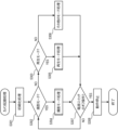
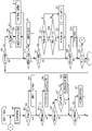
- FIG. 3 is a flowchart of camera activation processing according to this embodiment.
- FIG. 4 is a flowchart of shooting mode processing according to this embodiment.
- FIG. 5 is a flowchart of display-related processing according to this embodiment.
- FIG. 6 is a flowchart of playback mode processing according to this embodiment.
- 7A and 7B are diagrams for explaining screens of the display unit according to the present embodiment.
- 8A to 8C are diagrams for explaining screens for shooting mode processing according to the present embodiment.
- 9A to 9C are diagrams for explaining screens for shooting mode processing according to the present embodiment.
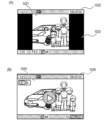
- 10A and 10B are diagrams for explaining screens of reproduction mode processing according to the present embodiment.
- the user does not want to perform specific processing in any of the multiple areas where the image is divided by the aspect markers when performing specific processing related to shooting. There is On the other hand, in certain cases, the user may wish to perform certain processing on an area including multiple areas into which the aspect marker divides the image.
- the user wants to upload the captured video to multiple SNSs. Specifically, based on one video file, the user uploads a video with an aspect ratio of 16:9 to the first SNS as a main video, and uploads a video with an aspect ratio of 1:1 as a promotional video to the second SNS. You may want to upload to your SNS.
- the user expects that various imaging functions such as AF and AE will be performed within the range of the aspect ratio (16:9) for the main moving image.
- the execution area of such an imaging function is restricted according to the position of the aspect marker (for example, AF is executed only in one of the regions divided by the aspect marker), and so on. video production may not be possible.
- FIG. 1A and 1B show external views of a digital camera 100 as an example of a device to which the present invention can be applied.
- 1A is a front perspective view of the digital camera 100
- FIG. 1B is a back perspective view of the digital camera 100.
- FIG. 1A is a front perspective view of the digital camera 100
- FIG. 1B is a back perspective view of the digital camera 100.
- the display unit 28 is a display unit provided on the back surface of the digital camera 100, and displays images and various information.
- the touch panel 70 a can detect a touch operation on the display surface (touch operation surface; touch operation member) of the display unit 28 .
- the viewfinder display section 43 is a display section provided on the upper surface of the digital camera 100 and displays various setting values of the digital camera 100 such as shutter speed and aperture.
- a shutter button 61 is an operation member for giving a photographing instruction (imaging instruction).
- the mode switching switch 60 is an operating member for switching between various modes.
- the terminal cover 40 is a cover that protects a connector (not shown) that connects the digital camera 100 to an external device.
- the main electronic dial 71 is a rotating operation member, and by turning the main electronic dial 71, it is possible to change the set values such as the shutter speed and aperture.
- the power switch 72 is an operation member for switching the power of the digital camera 100 between ON and OFF.
- the sub-electronic dial 73 is a rotary operation member, and by rotating the sub-electronic dial 73, the selection frame (cursor) can be moved, the image can be advanced, and the like.
- the 4-way key 74 is configured such that the up, down, left, and right portions can be pushed, respectively, and processing can be performed according to the pressed portion of the 4-way key 74 .
- the SET button 75 is a push button and is mainly used for determining selection items.
- a multi-controller (hereinafter referred to as MC) 65 can accept direction instructions in eight directions and a push operation in the central portion.
- the movie button 76 is used to instruct the start and stop of movie shooting (recording).
- the AE lock button 77 is a push button, and the exposure state can be fixed by pressing the AE lock button 77 in the shooting standby state.
- the enlargement button 78 is an operation button for switching between ON and OFF of the enlargement mode in the live view display (LV display) of the shooting mode. By operating the main electronic dial 71 after turning on the enlargement mode, the live view image (LV image) can be enlarged or reduced. In the reproduction mode, the enlargement button 78 functions as an operation button for enlarging the reproduced image and increasing the enlargement ratio.
- the playback button 79 is an operation button for switching between shooting mode and playback mode.
- the menu button 81 is a push button used to perform an instruction operation for displaying a menu screen.
- a menu screen on which various settings can be made is displayed on the display unit 28 .
- the user can intuitively perform various settings using the menu screen displayed on the display unit 28 and the 4-way key 74, SET button 75, or MC65.
- the line-of-sight confirmation button 82 is an operation member included in the operation unit 70, and is a push button for instructing execution or cancellation of selection of a subject based on the position of a line-of-sight pointer, which will be described later.
- the line-of-sight determination button is arranged at a position where it can be easily operated even when the user is looking through the viewfinder (a state where the eyepiece is focused on the eyepiece 16), and can be operated with the thumb of the right hand holding the grip 90.
- the communication terminal 10 is a communication terminal for the digital camera 100 to communicate with the lens unit 150 (described later; detachable).
- the eyepiece unit 16 is an eyepiece unit of an eyepiece finder (looking-in type finder), and the user can visually recognize an image displayed on an internal EVF 29 (described later) through the eyepiece unit 16 .
- the eyepiece detection unit 57 is an eyepiece detection sensor that detects whether or not the user (photographer) is eyeing the eyepiece unit 16 .
- a lid 202 is a lid for a slot that stores a recording medium 200 (described later).
- the grip part 90 is a holding part shaped so that the user can easily hold it with his or her right hand when holding the digital camera 100 .
- a shutter button 61 and a main electronic dial 71 are arranged at positions that can be operated with the index finger of the right hand while holding the digital camera 100 by gripping the grip portion 90 with the little finger, the ring finger and the middle finger of the right hand. Also, in the same state, the sub-electronic dial 73 and line-of-sight determination button 82 are arranged at positions that can be operated with the thumb of the right hand.
- FIG. 2 is a block diagram showing a configuration example of the digital camera 100.
- a lens unit 150 is a lens unit that mounts an interchangeable photographing lens. Although the lens 103 is normally composed of a plurality of lenses, only one lens is shown in FIG. 2 for the sake of simplicity.
- a communication terminal 6 is a communication terminal for the lens unit 150 to communicate with the digital camera 100 side
- a communication terminal 10 is a communication terminal for the digital camera 100 to communicate with the lens unit 150 side.
- the lens unit 150 communicates with the system control section 50 via these communication terminals 6 and 10 .
- the lens unit 150 controls the diaphragm 1 through the diaphragm driving circuit 2 by the lens system control circuit 4 inside. Also, the lens unit 150 focuses by displacing the lens 103 via the AF drive circuit 3 by the lens system control circuit 4 .
- the shutter 101 is a focal plane shutter that can freely control the exposure time of the imaging unit 22 under the control of the system control unit 50 .
- the image pickup unit 22 is an image pickup device configured by a CCD, CMOS device, or the like that converts an optical image into an electrical signal.
- the imaging unit 22 may have an imaging surface phase difference sensor that outputs defocus amount information to the system control unit 50 .
- the image processing unit 24 performs predetermined processing (resize processing such as pixel interpolation and reduction, color conversion processing, etc.) on data from the A/D converter 23 or data from the memory control unit 15 .
- the image processing unit 24 performs predetermined arithmetic processing using captured image data, and the system control unit 50 performs exposure control and distance measurement control based on the arithmetic results obtained by the image processing unit 24 .
- TTL through-the-lens
- AF autofocus
- AE automatic exposure
- EF flash pre-emission
- the image processing unit 24 further performs predetermined arithmetic processing using the captured image data, and performs TTL AWB (Auto White Balance) processing based on the obtained arithmetic result.
- the memory control unit 15 controls transmission and reception of data among the A/D converter 23 , the image processing unit 24 and the memory 32 .
- Output data from the A/D converter 23 is written into the memory 32 via the image processing section 24 and the memory control section 15 .
- the output data from the A/D converter 23 is written to the memory 32 via the memory control section 15 without passing through the image processing section 24 .
- the memory 32 stores image data obtained by the imaging unit 22 and converted into digital data by the A/D converter 23 and image data to be displayed on the display unit 28 and the EVF 29 .
- the memory 32 has a storage capacity sufficient to store a predetermined number of still images, moving images for a predetermined period of time, and audio.
- the memory 32 also serves as a memory for image display (video memory).
- the image data for display written in the memory 32 is displayed by the display section 28 or the EVF 29 via the memory control section 15 .
- Each of the display unit 28 and the EVF 29 performs display according to a signal from the memory control unit 15 on a display device such as LCD or organic EL.
- the data A/D-converted by the A/D converter 23 and accumulated in the memory 32 are sequentially transferred to the display unit 28 or the EVF 29 for display, thereby performing live view display (LV).
- An image displayed in live view display is hereinafter referred to as a live view image (LV image).
- the line-of-sight detection unit 160 detects the line of sight of the user's eye, which is brought into contact with the eyepiece unit 16 , looking at the EVF 29 .
- the line-of-sight detection unit 160 includes a dichroic mirror 162 , an imaging lens 163 , a line-of-sight detection sensor 164 , a line-of-sight detection circuit 165 and an infrared light emitting diode 166 .
- the infrared light emitting diode 166 is a light emitting element for detecting the user's line of sight position within the finder screen, and irradiates the user's eyeball (eye) 161 with infrared light. Infrared light emitted from an infrared light emitting diode 166 is reflected by an eyeball (eye) 161 , and the reflected infrared light reaches a dichroic mirror 162 . Dichroic mirror 162 reflects only infrared light and transmits visible light. The reflected infrared light whose optical path has been changed forms an image on the imaging surface of the line-of-sight detection sensor 164 via the imaging lens 163 .
- the imaging lens 163 is an optical member that constitutes the line-of-sight detection optical system.
- the line-of-sight detection sensor 164 is composed of an imaging device such as a CCD image sensor.
- the line-of-sight detection sensor 164 photoelectrically converts the incident infrared reflected light into an electric signal and outputs the electric signal to the line-of-sight detection circuit 165 .
- the line-of-sight detection circuit 165 detects the user's line-of-sight position from the movement of the user's eyeballs (eyes) 161 based on the output signal of the line-of-sight detection sensor 164 , and outputs the detection information to the system control unit 50 and the gaze determination unit 170 . .
- the gaze determination unit 170 determines that the user is gazing at the area when the period during which the user's line of sight is fixed on the area exceeds a predetermined threshold. do. Therefore, it can be said that the area is the gaze position (gazing area), which is the position where the gaze is performed.
- the line of sight is fixed in a certain area means, for example, that the average position of the movement of the line of sight is within the area until a predetermined period of time elapses, and the variation (dispersion) is greater than a predetermined value. is also less.
- the predetermined threshold can be arbitrarily changed by the system control unit 50 .
- the gaze determination unit 170 may not be provided as an independent block, and the system control unit 50 may perform the same function as the gaze determination unit 170 based on the detection information received from the line-of-sight detection circuit 165 .
- the line-of-sight detection unit 160 detects the line of sight using a method called the corneal reflection method.
- the corneal reflection method infrared light emitted from an infrared light emitting diode 166 is reflected by an eyeball (eye) 161 (especially the cornea), and the positional relationship between the reflected light and the pupil of the eyeball (eye) 161 is used to determine the line of sight.
- This method detects orientation and position.
- the method of detecting the line of sight (the direction and position of the line of sight) is not particularly limited, and methods other than the above may be used.
- a method called a scleral reflection method which utilizes the difference in light reflectance between the iris and the white of the eye, may be used.
- Various setting values of the camera such as shutter speed and aperture, are displayed on the viewfinder display section 43 via the viewfinder display section drive circuit 44 .
- the nonvolatile memory 56 is an electrically erasable/recordable memory, such as a FLASH-ROM. Constants for the operation of the system control unit 50, programs, and the like are recorded in the nonvolatile memory 56.
- FIG. The program here is a program for executing various flowcharts described later in this embodiment.
- the system control unit 50 is a control unit consisting of at least one processor or circuit, and controls the digital camera 100 as a whole.
- the system control unit 50 executes the program recorded in the non-volatile memory 56 described above, thereby realizing each process of this embodiment described later.
- the system memory 52 is, for example, a RAM.
- the system control unit 50 also performs display control by controlling the memory 32, the display unit 28, and the like.
- the system timer 53 is a timing unit that measures the time used for various controls and the time of the built-in clock.
- the power supply control unit 80 is composed of a battery detection circuit, a DC-DC converter, a switch circuit for switching blocks to be energized, and the like, and detects whether or not a battery is installed, the type of battery, and the remaining amount of the battery. Also, the power supply control unit 80 controls the DC-DC converter based on the detection results and instructions from the system control unit 50, and supplies necessary voltage to each unit including the recording medium 200 for a necessary period.
- the power supply unit 30 is composed of a primary battery (alkaline battery, lithium battery, etc.), a secondary battery (NiCd battery, NiMH battery, Li battery, etc.), an AC adapter, or the like.
- a recording medium I/F 18 is an interface with a recording medium 200 such as a memory card or hard disk.
- a recording medium 200 is a recording medium such as a memory card for recording captured images, and is composed of a semiconductor memory, a magnetic disk, or the like.
- the communication unit 54 transmits and receives image signals and audio signals to and from an external device connected wirelessly or by a wired cable.
- the communication unit 54 can be connected to a wireless LAN (Local Area Network) and the Internet. Also, the communication unit 54 can communicate with an external device using Bluetooth (registered trademark) or Bluetooth Low Energy.
- the communication unit 54 can transmit images (including LV images) captured by the imaging unit 22 and images recorded in the recording medium 200, and can receive image data and other various information from external devices.
- the orientation detection unit 55 detects the orientation of the digital camera 100 with respect to the direction of gravity. Based on the posture detected by the posture detection unit 55, whether the image captured by the imaging unit 22 is an image captured with the digital camera 100 held horizontally or an image captured with the digital camera 100 held vertically. can be determined.
- the system control unit 50 can add direction information corresponding to the posture detected by the posture detection unit 55 to the image file of the image captured by the imaging unit 22, or can rotate and record the image. be.
- An acceleration sensor, a gyro sensor, or the like can be used as the posture detection unit 55 . It is also possible to detect the movement of the digital camera 100 (pan, tilt, lift, whether it is stationary, etc.) using an acceleration sensor or a gyro sensor, which is the posture detection unit 55 .
- the eyepiece detection unit 57 detects approach (eye contact) and departure (eye separation) of the eye (object) 161 from the eyepiece unit 16 of the eyepiece finder (hereinafter simply referred to as "finder") (approach detection). It is a detection sensor.
- the system control unit 50 switches display (display state)/non-display (non-display state) of the display unit 28 and the EVF 29 according to the state detected by the eye proximity detection unit 57 . More specifically, at least in the shooting standby state and when the switching of the display destination is automatic switching, the display destination is set to the display unit 28 and the display is turned on while the EVF 29 is not displayed.
- the display destination is set to the EVF 29, and the display is turned on, and the display unit 28 is turned off.
- an infrared proximity sensor can be used as the eyepiece detection unit 57 , and it is possible to detect the approach of any object to the eyepiece unit 16 of the viewfinder containing the EVF 29 .
- an infrared ray projected from a light projecting unit (not shown) of the eyepiece detection unit 57 is reflected by the object and received by a light receiving unit (not shown) of the infrared proximity sensor. It is also possible to determine how close the object is from the eyepiece 16 (eyepiece distance) based on the amount of received infrared rays.
- the eye proximity detection unit 57 performs eye proximity detection for detecting the proximity distance of an object to the eyepiece unit 16 .
- an object approaching within a predetermined distance from the eyepiece unit 16 is detected from the non-eyepiece state (non-approach state)
- the threshold for detecting eye contact and the threshold for detecting eye detachment may be different, for example, by providing hysteresis.
- the eye contact state is assumed until eye separation is detected.
- the eye contact detection unit 57 it is assumed that, after eye separation is detected, the eye is in a non-eye contact state until eye contact is detected.
- the infrared proximity sensor is only an example, and other sensors may be employed as the eye contact detection unit 57 as long as they can detect the approach of an eye or an object that can be regarded as an eye contact.
- the system control unit 50 can detect the following line-of-sight states toward the EVF 29 by controlling the line-of-sight detection unit 160 .
- the line of sight that was not directed to the EVF 29 is now directed to the EVF 29 . That is, the start of line-of-sight input.
- a state in which no line of sight is input to the EVF 29 (a state in which the EVF 29 is not seen).
- the system control unit 50 is notified of these operations/states and the position (direction) in which the line of sight is directed to the EVF 29 via an internal bus. determine whether the
- the operation unit 70 is an input unit that receives operations (user operations) from the user, and is used to input various operation instructions to the system control unit 50 .
- the operation unit 70 includes a mode switching switch 60, a shutter button 61, a power switch 72, a touch panel 70a, and the like.
- the operation unit 70 also includes other operation members 70b such as a main electronic dial 71, a sub electronic dial 73, a 4-way key 74, a SET button 75, a movie button 76, an AE lock button 77, an enlargement button 78, a playback button 79, A menu button 81, MC65, etc. are included.
- the mode switching switch 60 switches the operation mode of the system control unit 50 to any one of still image shooting mode, moving image shooting mode, playback mode, and the like.
- Modes included in the still image shooting mode include auto shooting mode, auto scene discrimination mode, manual mode, aperture priority mode (Av mode), shutter speed priority mode (Tv mode), and program AE mode (P mode).
- a mode change switch 60 allows the user to switch directly between these modes.
- the movie shooting mode may also include multiple modes.
- the shutter button 61 has a first shutter switch 62 and a second shutter switch 64 .
- the first shutter switch 62 is turned on when the shutter button 61 is being operated, that is, when the shutter button 61 is half-pressed (imaging preparation instruction), and generates a first shutter switch signal SW1.
- the system control unit 50 starts shooting preparation operations such as AF (autofocus) processing, AE (auto exposure) processing, AWB (auto white balance) processing, and EF (flash pre-flash) processing in response to the first shutter switch signal SW1. do.
- the second shutter switch 64 is turned ON when the operation of the shutter button 61 is completed, that is, when the shutter button 61 is fully pressed (imaging instruction), and generates a second shutter switch signal SW2.
- the system control unit 50 starts a series of photographing processing operations from signal reading from the imaging unit 22 to writing of the photographed image as an image file on the recording medium 200.
- the touch panel 70a and the display unit 28 can be configured integrally.
- the touch panel 70 a is configured so that the light transmittance does not interfere with the display of the display section 28 and is attached to the upper layer of the display surface of the display section 28 .
- the input coordinates on the touch panel 70a and the display coordinates on the display surface of the display unit 28 are associated with each other. This makes it possible to provide a GUI (graphical user interface) as if the user could directly operate the screen displayed on the display unit 28 .
- the system control unit 50 can detect the following operations or states on the touch panel 70a.
- the touch panel 70a is newly touched by a finger or pen that has not touched the touch panel 70a, that is, the start of touch (hereinafter referred to as Touch-Down).
- Touch-On A state in which the touch panel 70a is touched with a finger or a pen (hereinafter referred to as Touch-On).
- touch-move The finger or pen is moving while touching the touch panel 70a (hereinafter referred to as touch-move).
- touch-Up The finger or pen touching the touch panel 70a is released from the touch panel 70a, that is, the end of the touch (hereinafter referred to as Touch-Up).
- Touch-Off A state in which nothing is touched on the touch panel 70a
- a touchon is also detected at the same time. After touchdown, touchon continues to be detected unless touchup is detected. Touch-on is detected at the same time when touch-move is detected. Even if touch-on is detected, touch-move is not detected if the touch position does not move. After it is detected that all the fingers and pens that have touched have touched up, the touch is turned off.
- the system control unit 50 is notified of these operations/states and the coordinates of the position where the finger or pen touches the touch panel 70a through the internal bus. Based on the notified information, the system control unit 50 determines what kind of operation (touch operation) has been performed on the touch panel 70a. As for the touch move, the moving direction of the finger or pen moving on the touch panel 70a can also be determined for each vertical component/horizontal component on the touch panel 70a based on the change in the position coordinates. It is determined that a slide operation has been performed when it is detected that the touch-move has been performed for a predetermined distance or more. An operation in which the finger is quickly moved by a certain distance while touching the touch panel 70a and then released is called a flick.
- a flick is, in other words, an operation of quickly tracing the touch panel 70a as if flicking it with a finger. It can be determined that a flick has been performed when a touch-move of a predetermined distance or more at a predetermined speed or more is detected, and a touch-up is detected as it is (it can be determined that a flick has occurred following a slide operation). Further, a touch operation of touching (multi-touching) a plurality of points (for example, two points) to bring the touch positions closer to each other is called pinch-in, and a touch operation of moving the touch positions away from each other is called pinch-out. Pinch-out and pinch-in are collectively called pinch operation (or simply pinch).
- the touch panel 70a may be of any of various types of touch panels such as a resistive film type, a capacitive type, a surface acoustic wave type, an infrared type, an electromagnetic induction type, an image recognition type, an optical sensor type, and the like. good. There is a method of detecting that there is a touch when there is contact with the touch panel, and a method of detecting that there is a touch when there is an approach of a finger or pen to the touch panel.
- the digital camera 100 may be provided with an audio input unit (not shown) for transmitting to the system control unit 50 obtained from a built-in microphone or an audio input device connected via an audio input terminal.
- the system control unit 50 selects the input audio signal as necessary, performs analog-to-digital conversion, performs level optimization processing, specific frequency reduction processing, and the like, and generates an audio signal.
- the user sets the method of specifying the position of the position index (for example, the AF frame) when the touch-move operation is performed in the eye-focused state to either the absolute position specification method or the relative position specification method. can do.
- the absolute position specifying method is a method in which input coordinates on the touch panel 70a and display coordinates on the display surface of the EVF 29 are associated.
- an AF frame is set at a position associated with the touched position (position whose coordinates are input) even if there is no touch-move (before touchdown). position).
- the position set by the absolute positioning method is based on the touched-down position, regardless of the position set before the touchdown.
- the relative position specifying method is a method in which input coordinates on the touch panel 70a and display coordinates on the display surface of the EVF 29 are not associated with each other. In the case of the relative position specifying method, when there is only a touchdown on the touch panel 70a and there is no touch-move, the position of the AF frame does not move from the position before the touchdown.
- the position of the currently set AF frame (the position set before touch-down) will move in the direction of the touch-move movement according to the amount of movement of the touch-move.
- the position of the AF frame moves by the distance.
- AF area As the AF area (AF frame setting method), one of a plurality of AF methods including "single point AF" and “whole area AF” can be set. In addition, it is possible to set whether or not to detect the subject (tracking).
- One-point AF is a method in which a user designates one point as a position for performing AF using a one-point AF frame.
- “Whole area AF” is a method in which the AF position is automatically set based on automatic selection conditions when the user does not designate a tracking target.
- the face By multiplying these AF area settings, it is possible to reflect the tracking settings, and if the tracking is set to "Yes", if a person's face is detected from the LV image, the face will be prioritized as the AF target subject mode to select.
- the size of the face is large, the position of the face is close to the digital camera 100 (closest side), the position of the face is close to the center in the image, and the pre-registered individual is detected.
- One face is selected according to priority such as being a face and set as an AF target subject.
- a person's face is not detected, other than the face is detected according to the priority, such as close to the digital camera 100 (closest side), high contrast, high priority subject such as animal or vehicle, or moving object. , and set it as an AF target subject.
- the priority such as close to the digital camera 100 (closest side)
- high contrast high priority subject such as animal or vehicle, or moving object.
- the subject to be tracked is set as an AF target subject. That is, the automatic selection conditions are weighted using at least one element condition among the element conditions shown in the example below, and the obtained score is equal to or greater than a predetermined threshold, or the obtained score is the highest. It is a condition. - It is the face of the detected person. ⁇ The size of the face is large. - The position of the face is close to the digital camera 100 (closest side).
- ⁇ It is a pre-registered individual face. - Close to the digital camera 100 (closest side). ⁇ High contrast. ⁇ The subject is a high-priority subject such as an animal or vehicle. ⁇ It is a moving body.
- FIG. 3 shows a flowchart of camera activation processing of the digital camera 100 according to this embodiment.
- the processing of the flowchart shown in FIG. 3 is realized by the system control unit 50 expanding the program stored in the nonvolatile memory 56 into the system memory 52 and executing the program.
- the digital camera 100 is activated in the photographing mode in response to the power switch 72 being turned on, the flags, control variables, etc. are initialized, and the processing of the flowchart shown in FIG. 3 is started.
- the system control unit 50 executes initialization processing of various flags for camera startup processing.
- the system control unit 50 determines whether the operation mode of the digital camera 100 is the shooting mode. If the operation mode of the digital camera 100 is the shooting mode, the process proceeds to S304; otherwise, the process proceeds to S303.
- the system control unit 50 determines whether the operation mode of the digital camera 100 is playback mode. If the operation mode of the digital camera 100 is the reproduction mode, the process proceeds to S305; otherwise, the process proceeds to S306.
- the system control unit 50 performs shooting mode processing (see FIGS. 4 and 5), which will be described later.
- the system control unit 50 performs the later-described reproduction mode process (see FIG. 6).
- the system control unit 50 performs other mode processing. For example, the system control unit 50 switches to the wireless communication mode and performs processing of transmitting the captured image file to another device.
- the system control unit 50 determines whether an operation to turn off the power switch 72 (off operation) has been performed. If the power switch 72 is turned off, the process proceeds to S308; otherwise, the process proceeds to S302.
- the system control unit 50 stores various flags for camera termination processing, etc., and stops the operation of the digital camera 100 .
- FIG. 1 photographing mode processing when the digital camera 100 photographs a subject will be described with reference to FIGS. 4 and 5.
- reproduction mode processing when the digital camera 100 reproduces the photographed image will be described.
- the system control unit 50 displays a live view image on the display unit 28, and displays two aspect markers that divide the live view image into three areas superimposed on the live view image.
- the live view image displayed on the display unit 28 is divided into an inner area, which is an area close to the center of the screen of the display unit 28, and two outer areas, which are farther from the center of the screen than the inner area, by the two aspect markers. (see FIG. 8A). Below, the two outer regions are simply described as outer regions without distinction.
- the digital camera 100 records only the inner area of the areas into which the live view image is divided by the aspect markers when shooting.
- the digital camera 100 records both the inner area and the outer area when shooting.
- the digital camera 100 limits the recording target to the inner area only, and also includes specific processing related to capturing (moving range of the AF frame, etc.) in the inner area.
- both the area to be photographed and the area to be subjected to AF can be set to the inner area, so that the area outside the area to be photographed in the still image after being photographed will not be in focus. It is possible to suppress and obtain a suitable still image.
- the area intended by the user is in focus at the time of photographing, it is possible to reduce the number of times required for preparing to photograph a still image.
- FIG. 4 is a flowchart for explaining main processing of the shooting mode processing (processing of S304) of the digital camera 100 according to this embodiment.
- the processing of the flowchart shown in FIG. 4 is realized by the system control unit 50 loading the program stored in the nonvolatile memory 56 into the system memory 52 and executing the program.
- the system control unit 50 performs display-related processing, which will be described later using FIG.
- the system control unit 50 performs processing for changing various settings in the menu.
- the system control unit 50 determines whether or not a mode switching operation has been performed on the operation unit 70 to switch between shooting modes (still image mode and moving image mode). If the mode switching operation has been performed, the process proceeds to S403; otherwise, the process proceeds to S404.
- the system control unit 50 switches the shooting mode. Specifically, the system control unit 50 switches to the moving image mode if the current shooting mode is the still image mode, and switches to the still image mode if the current shooting mode is the moving image mode.
- FIG. 7A is an example of the first layer of the menu screen displayed on the display unit 28.
- the user selects a desired shooting mode by selecting either a still image 701a (an option representing a still image mode) or a moving image 701b (an option representing a moving image mode) in the mode switching item 701. It is possible to choose. Therefore, it can be said that the mode switching operation is an operation of selecting an option representing a shooting mode other than the current shooting mode.
- the system control unit 50 switches the shooting mode according to the option selected by the user's operation on the operation unit 70 . For other items on the menu screen, the user can similarly select one of a plurality of options to switch the setting of the item.
- the system control unit 50 determines whether or not a display switching operation has been performed on the operation unit 70 to switch the aspect marker display setting.
- Aspect marker display settings are settings for whether or not to display aspect markers, and settings for the aspect ratio of the inner region when displaying aspect markers. If the display switching operation has been performed, the process proceeds to S405; otherwise, the process proceeds to S406.
- the menu screen changes from the first layer screen to a dedicated screen (second layer screen) for selecting options for the aspect marker shown in FIG. 7B. Transition.
- the dedicated screen displays an option 702a that does not display an aspect marker, and options 702b to 702f that display an aspect marker such that the inner area has a predetermined aspect ratio.
- the user performs a display switching operation by selecting one of the options 702a to 702f.
- Options 702b-702f are options representing displaying aspect markers so that the aspect ratios of the inner region are 1:1, 4:5, 5:4, 9:16, and 2.35:1, respectively.
- the aspect marker is not limited to the aspect marker. That is, instead of the aspect marker, arbitrary auxiliary lines (for example, grid lines) related to shooting may be used.
- auxiliary lines for example, grid lines
- the system control unit 50 switches the aspect marker display setting according to the display switching operation (which of the options 702a to 702f is selected).
- the system control unit 50 determines whether the current shooting mode is the still image mode. If the current shooting mode is the still image mode, the process proceeds to S407; otherwise (if the current shooting mode is the moving image mode), the process proceeds to S409.
- the system control unit 50 determines whether or not a GUI switching operation, which is an operation for switching range display settings, has been performed on the operation unit 70.
- the range display setting is the setting of the display (display form) of the GUI indicating the shooting range when shooting a still image. If the GUI switching operation has been performed, the process proceeds to S408; otherwise, the process proceeds to S409.
- the user can perform a GUI switching operation by selecting either "line only” or “mask” in the range display setting item 703 in FIG. 7A. Specifically, the user can perform an operation of selecting "setting to represent the imaging range only with aspect markers" (line display setting) by selecting the option of "line only”. On the other hand, the user selects an option of "Mask” to perform an operation of selecting "a setting to represent the shooting range with an aspect marker and to cover the outer area with a mask” (mask display setting). It can be carried out.
- the “mask” in this embodiment refers to a display superimposed on the live view image. The live view image may be completely invisible (the transparency of the mask is 0) due to the mask display, or a mask having a degree of transparency that allows the live view image to be visually recognized may be used.
- the system control unit 50 switches the range display setting according to the GUI switching operation.
- the system control unit 50 determines whether or not a setting switching operation has been performed on the operation unit 70 to switch AF-related settings. If the setting switching operation has been performed, the process proceeds to S410; otherwise, the process proceeds to S411.
- the user can perform a setting switching operation by selecting one of a plurality of AF methods including "single point AF" and "whole area AF" in the AF area item 704. Also, the user can perform a setting switching operation by selecting whether or not to detect a subject in the tracking item 705 .
- the system control unit 50 switches AF-related settings according to the setting switching operation.
- the system control unit 50 determines whether or not a shooting start operation, which is an operation for starting shooting, has been performed on the operation unit 70. If the shooting start operation has been performed, the process proceeds to S412; otherwise, the process proceeds to S415.
- the system control unit 50 determines whether or not the current shooting mode is the still image mode. If the current shooting mode is the still image mode, the process advances to S413. If the current shooting mode is the moving image mode, the process proceeds to S414.
- the system control unit 50 starts recording only the inner area of the live view image displayed on the display unit 28 as still image shooting start processing.
- the system control unit 50 starts recording the entire live view image displayed on the display unit 28, including not only the inner area but also the outer area, as moving image shooting start processing.
- the system control unit 50 determines whether or not a shooting end operation, which is an operation for ending shooting, has been performed on the operation unit 70. If the photographing end operation has been performed, the process proceeds to S416; otherwise, the process proceeds to S417.
- the system control unit 50 performs a photographing end process.
- the photographing end processing includes processing for arranging the recorded image on a medium in a predetermined format, processing for releasing the buffer used during photographing, and the like.
- the system control unit 50 stores the shot still image in the recording medium 200 as an image file of the still image (still image file).
- the system control unit 50 stores the captured moving image in the recording medium 200 as a moving image file (moving image file).
- the system control unit 50 determines whether or not to move the AF frame. For example, when "single-point AF" is set as the AF method, if an operation for moving the AF frame (AF frame moving operation) is performed, the system control unit 50 determines to move the AF frame. do.
- the AF frame moving operation refers to a user's touch operation on the touch panel 70a, an operation on any one of the four direction keys 74, or the like.
- the system control unit 50 determines to move the AF frame. If the AF frame is to be moved, proceed to S418; otherwise, proceed to S422.
- the system control unit 50 determines whether the AF frame is about to move to a position (outer area) outside the aspect marker. For example, when "single-point AF" is set as the AF method, if a position in the outer area is designated by the AF frame moving operation, the system control unit 50 determines that the AF frame is about to move to the outer area. I judge. On the other hand, when the AF method is set to "whole area AF", when the subject for which the AF frame is set (for example, the subject to be tracked for which AF continues to be performed) moves to the outer area, system control The unit 50 determines that the AF frame is about to move to the outer area.
- the process proceeds to S419; otherwise, the process proceeds to S421. If it is determined in S417 that the AF frame is to be moved without executing the process of S418, the process may proceed to S419.
- the system control unit 50 determines whether or not an AF frame movement range limitation flag (restriction flag), which will be described later, is ON. If the restriction flag is ON, the process proceeds to S420; otherwise, the process proceeds to S421.
- the restriction flag indicates whether AF frame movement (AF) is executable or not.
- the system control unit 50 moves the AF frame to perform AF in the inner area. For example, when "single-point AF" is set as the AF method, the system control unit 50 selects a position within the inner region where the AF frame can be moved and which is instructed by the AF frame movement operation instruction. AF frame is moved to a position closest to , and AF is performed at that position. On the other hand, when the "whole area AF" is set as the AF method, the system control unit 50 executes AF only for the tracking target subject located in the inner area.
- the system control unit 50 performs AF by moving the AF frame in the entire live view image including the inner area and the outer area, regardless of the position of the aspect marker. For example, when "single-point AF" is set as the AF method, the system control unit 50 moves the AF frame to the position indicated by the AF frame movement operation instruction, and performs AF at that position. On the other hand, when the AF method is set to “all area AF”, the system control unit 50 moves the AF frame to a position where it overlaps the tracking target subject in the entire live view image, and Execute AF. Note that if it is determined in S418 that the AF frame is not about to move to the outer area, the AF frame will not move to the outer area, and as a result, AF will be executed only in the inner area in S421. .
- the system control unit 50 determines whether or not another operation has been performed on the operation unit 70. If another operation has been performed, the process proceeds to S423; otherwise, the process proceeds to S424.
- the system control unit 50 performs other processing according to other operations.
- other operations and other processing are, for example, operations for changing other parameters (shutter speed, exposure compensation, etc.) related to photography and processing based thereon.
- the system control unit 50 determines whether or not the operation unit 70 has been operated to end the shooting mode. If the shooting mode end operation has been performed, the processing of this flowchart ends, otherwise the process advances to step S401.
- the end operation corresponds to, for example, a switching operation between shooting mode and playback mode.
- FIG. 5 is a flowchart of display-related processing of the digital camera 100 according to this embodiment.
- the processing of the flowchart shown in FIG. 5 is realized by the system control unit 50 expanding the program stored in the nonvolatile memory 56 into the system memory 52 and executing the program.
- the system control unit 50 displays a live view image on the display unit 28 based on the signal detected by the imaging unit 22.
- the system control unit 50 displays an aspect marker on the display unit 28 according to the aspect marker display setting so as to be superimposed on the live view image.
- the system control unit 50 determines whether the current shooting mode is the still image mode. If the current shooting mode is the moving image mode, the process proceeds to S507; otherwise, the process proceeds to S504.
- the system control unit 50 if the range display setting is the mask display setting, the system control unit 50 superimposes and displays the mask on the outer region on the display unit 28 (see FIG. 8B). On the other hand, if the range display setting is the line display setting, the system control unit 50 does not display the mask (see FIG. 8A).
- the system control unit 50 causes the display unit 28 to display a still image OSD indicating information related to the still image mode, such as the still image mode information display 802 in FIG. 8A, superimposed on the live view image. do.
- Information related to the still image mode includes information such as the number of shots that can be taken, remaining battery capacity, ISO sensitivity, shutter speed, or aperture value, for example.
- the system control unit 50 turns ON the restriction flag (AF frame movement range restriction flag).
- the restriction flag AF frame movement range restriction flag.
- the system control unit 50 displays, on the display unit 28, a moving image OSD indicating information related to the moving image mode, such as the moving image mode information display 912 in FIG. 9A, superimposed on the live view image.
- Information related to the movie mode includes, for example, information such as recordable time, remaining battery capacity, ISO sensitivity, or aperture value.
- the system control unit 50 turns off the restriction flag.
- the AF frame moves in the entire area of the live view image including the inner area and the outer area, and AF is performed in the entire area of the live view image. That is, the system control unit 50 enables movement of the AF frame and execution of AF with respect to the inner area and the outer area.
- the system control unit 50 superimposes an AF frame on the live view image and displays it on the display unit 28 based on the current AF-related settings.
- FIG. 8A to 9C are screen examples in shooting mode processing of the digital camera 100 according to the embodiment.
- FIG. 8A is the screen of the display unit 28 in still image mode.
- FIG. 8A shows the screen at the end of the process of S509 when the shooting mode is the still image mode (NO in S503) and the mask is not displayed in S504.
- FIG. 8A is a screen example when the range display setting is a line display setting (setting in which only aspect markers are displayed).
- a still image mode information display 802 , an aspect marker 803 , and an AF frame 804 are displayed superimposed on a live view image 801 .
- Aspect marker 803 is hereinafter an example of an aspect marker that sets the aspect ratio of the inner region to 1:1.
- the restriction flag is ON, the AF frame 804 is not displayed outside (outer region) the two aspect markers 803, and AF is not executed.
- FIG. 8B is a screen example of the display unit 28 when the range display setting is the mask display setting (the mask is also displayed).
- FIG. 8B shows the screen at the end of the process of S509 when the shooting mode is the still image mode (NO in S503) and the mask is displayed in S504.
- a mask 805 is displayed superimposed on the live view image 801, and only the live view image 801 inside the two aspect markers 803 is displayed.
- the example of FIG. 8B has the advantage that it is easy to have an image of the image after shooting.
- the example of FIG. 8A has the advantage that it is easy to capture the state of the subject outside the shooting range, and it is easy to change the aspect ratio of the inner area (change the position of the aspect marker 803).
- FIG. 8C is a screen example of the display section 28 in the shooting preparation state in the still image mode.
- FIG. 8C is a screen at the end of the process of S423 when the first shutter switch 62 is operated as another operation of S422 while the screen of FIG. 8A is being displayed.
- the state transitions to this photographing preparation state.
- a live view image 801 and an aspect marker 803 are displayed in the same manner as in FIG. 8A.
- FIG. 8C also displays an information display 806 corresponding to the shooting state (including the shooting preparation state) and a focus frame 807 indicating the result of AF execution. Since the restriction flag is ON in the still image mode, the focus frame 807 is never displayed outside the aspect marker 803 .
- the second shutter switch 64 when the second shutter switch 64 is operated to take a picture while the screen shown in FIG. 8C is displayed, if the user has set the silent shutter, the outer periphery of the live view image will be displayed.
- a perimeter frame is displayed, which is a frame drawn along.
- the silent shutter setting is a setting that does not make the shutter sound when shooting.
- the outer frame is a frame for notifying the user of the shooting timing (that the shooting is being performed) in order to solve the problem that the shooting timing cannot be recognized because there is no shutter sound.
- FIG. 9A is an example of the screen of the display section 28 in the moving image mode.
- FIG. 9A is the screen at the end of the process of S509 when the shooting mode is the moving image mode (YES in S503).
- a moving image mode information display 912 an aspect marker 913 , a mask 914 , and an AF frame 915 are displayed superimposed on a live view image 911 .
- the AF frame 915 can be displayed in the outer area (outside the aspect marker 913).
- FIG. 9B is the screen at the end of the process of S414 when the operation to start moving image shooting is performed while the screen of FIG. 9A is displayed (YES in S411 and NO in S412).
- FIG. 9B is a screen example during moving image recording, and unlike FIG. 9A, an information display 916 corresponding to the moving image recording state is displayed. Even in this case, since the restriction flag is OFF, the AF frame 915 can be displayed in the outer area.
- the display unit 28 may simultaneously display an aspect marker and a marker (auxiliary line) other than the aspect marker.
- the display unit 28 may display grid lines 917 for confirming the position of the subject in the live view image 911 together with the aspect markers 913, as shown in FIG. 9C.
- the system control unit 50 does not have to restrict the movement of the AF frame in the two areas divided by the grid line 917 regardless of the restriction flag. That is, the system control unit 50 may perform AF by moving the AF frame in an area including both of the two areas divided by the grid line 917, regardless of which shooting mode is selected. .
- the system control unit 50 can move the AF frame (AF execution) may not be restricted (disabled).
- the system control unit 50 sets the AF frame in the area including the two or more areas. may be moved to perform AF.
- the system control unit 50 does not move the AF frame in the area including the two or more areas in the movie mode. , AF may not be executed. Further, the system control unit 50 may hide the grid lines 917 when recording of a still image or moving image is started (when shooting is started).
- control for limiting the movement of the AF frame (limiting the AF execution range) according to the mode for an image containing two areas divided by an auxiliary line such as an aspect marker explained.
- the user can obtain an image subjected to AF within the range of the image (moving image) to be finally used, and it is possible to recapture the image (moving image). load can be reduced.
- FIG. 6 is a flowchart of playback mode processing of the digital camera 100 according to this embodiment.
- the processing of the flowchart shown in FIG. 6 is realized by the system control unit 50 loading the program stored in the nonvolatile memory 56 into the system memory 52 and executing the program.
- the system control unit 50 acquires the image file stored in the recording medium 200.
- the system control unit 50 reproduces the acquired image file as an image on the display unit 28.
- the system control unit 50 determines whether the image file acquired at S601 is a moving image file. If the image file is a moving image file, the process proceeds to S605; otherwise, the process proceeds to S604.
- system control unit 50 superimposes the information on the still image file and the still image GUI for performing operations on the still image file on the display unit 28 on the image being reproduced.
- FIG. 10A is a screen example of the display unit 28 showing the playback state of a still image.
- a still image GUI 1022 is displayed superimposed on the image 1021 being reproduced.
- the image 1021 being played back is an image file that was shot based on the setting of the aspect ratio of 1:1 in S413, blank areas 1023 that are not recorded are displayed on both sides of the image 1021. ing.
- the system control unit 50 superimposes information on the moving image file and moving image GUI for operating the moving image file on the display unit 28 on the image being reproduced.
- FIG. 10B is a screen example of the display unit 28 showing the playback state of the moving image.
- a moving image GUI 1025 is displayed superimposed on the image 1024 being reproduced.
- an image 1024 being played back is a file shot in S414 based on the setting of the aspect ratio of the inner area to 1:1. According to FIG. 10B, it can be seen that the area outside the aspect marker (outside area) is also recorded.
- the system control unit 50 determines whether or not an image switching operation has been performed on the operation unit 70 to switch the image file displayed on the display unit 28 to the next file. If an image switching operation has been performed, the process proceeds to S607; otherwise, the process proceeds to S608.
- the system control unit 50 switches the image file to be displayed (reproduced) on the display unit 28 to the next file.
- the system control unit 50 determines whether or not another operation has been performed on the operation unit 70. If another operation has been performed, the process proceeds to S609; otherwise, the process proceeds to S610.
- the system control unit 50 performs other processing.
- other operations and other processing are, for example, operations for changing other parameters related to reproduction (reproduction speed, brightness of the display section 28, etc.) and processing based thereon.
- the system control unit 50 determines whether or not the operation unit 70 has been operated to end the reproduction mode process. If the playback mode processing end operation is performed, the processing of this flowchart ends. Otherwise, proceed to S602.
- the termination operation of the reproduction mode process corresponds to, for example, an operation for switching between the shooting mode and the reproduction mode.
- auxiliary lines such as aspect markers
- AF is performed only in the area inside the image divided by the aspect marker (within the area of the image whose aspect ratio is adjusted by the aspect marker).
- the aspect marker is set to be displayed and in the still image mode
- AF is performed only in the area inside the image divided by the aspect marker (within the area of the image whose aspect ratio is adjusted by the aspect marker).
- the area outside the auxiliary lines is not used. In such a case, if the image is focused on the area outside the auxiliary line, there is no focus position in the image to be used inside the auxiliary line, and the image may not be desired by the user.
- the system control unit 50 performs AF not only on the inner area of the aspect marker, but also on the outer area.
- the still image mode there are cases where the area outside the aspect marker is not used, so it is considered that there will be little inconvenience even if AF is performed only within a narrower range than the image actually captured.
- moving image mode if AF cannot be performed only in a range narrower than the moving image that is actually captured, focusing can be performed only in a part of the range that can be captured, which is very inconvenient for the user.
- the system control unit 50 performs control so that AF is performed (focused) only within the range of the image that the user will use, according to the shooting mode.
- AF is a specific process related to shooting, for a desired range depending on the situation.
- the system control unit 50 determines the AF execution range according to whether the mode is a mode for shooting only the inner area or a mode for shooting the entire live view image.
- a process of whether or not to restrict may be executed.
- the system control unit 50 may turn ON the restriction flag in the mode for capturing only the inner region, and turn the restriction flag OFF in the mode for capturing the entire live view image.
- the mode for photographing only the inner area is a mode in which only the image (inner area) within the two aspect markers is recorded without including the outer area.
- a mode for shooting the entire live view image is a mode that records an image that includes the inner area and the outer area, and also includes the area outside the aspect marker.
- the specific processes subject to restrictions are AE, the process of setting (displaying) the center position of the enlarged display of the live view image (the center position when the live view image is enlarged and displayed), the degree of focus with the subject (focus state ) may be displayed (focus guide).
- the specific process may be a process of setting (displaying) a white acquisition position for manual white balance.
- auxiliary information other than the aspect marker such as auxiliary lines
- the system control unit 50 limits the movement range of the AF frame according to the position of the aspect marker, but does not limit the movement range of the AF frame according to other auxiliary information (regardless of the auxiliary information).
- the movement of the AF frame may be made executable at first, or may be restricted. For example, when displaying safety zones separated by auxiliary lines, the system control unit 50 limits the movement range of the AF frame to the safety zone (execution of AF in the safety zone) even in the movie mode. (the execution of AF is disabled).
- the system control unit 50 does not move the AF frame and does not perform AF in the safety zone of the two areas divided by the auxiliary line for indicating the safety zone, regardless of which shooting mode is selected. You may do so.
- the safety zone is supplementary information that indicates a range that cannot be completely seen even if a telop or the like is inserted in editing, assuming distribution on multiple media such as PCs and televisions.
- the system control unit 50 can change whether to turn on the restriction flag according to the option for selecting the aspect ratio of the inner region (see FIG. 7B). good.
- the restriction flag when the restriction flag is turned ON, the system control unit 50 moves the AF frame only in the inner area to perform AF.
- the restriction flag is turned OFF, the system control unit 50 moves the AF frame to the area including both the inner area and the outer area to perform AF.
- the aspect ratio of the inner region is 1:1
- the system control unit 50 generates a normal video with an aspect ratio of 16:9 and a 1:1 video to be posted on SNS or the like. , and the restriction flag is set to OFF.
- the system control unit 50 assumes that the purpose is only to shoot the main part of the movie,
- the movement restriction of the AF frame may be turned ON even in the mode.
- the system control unit 50 can turn off the restriction flag when a subject is selected by the user and the subject is tracked as the main subject. good.
- the system control unit 50 may turn off the restriction flag even in the still image mode (regardless of the shooting mode).
- Predetermined cases include cases where a subject authenticated and registered as an individual is indicated by an AF frame (when the subject for AF is a pre-registered subject), and settings assuming a moving subject with AF-related settings. (SERVO or tracking) is performed.
- SERVO continuous means that when a predetermined condition is satisfied (for example, the first shutter switch 62 is continuously pressed), the subject is tracked and the subject is kept in focus (focus is maintained). ) setting.
- the system control unit 50 has a high possibility that the object will move greatly.
- the flag may be turned OFF.
- the system control unit 50 can operate a specific operation unit (for example, the line-of-sight detection circuit 165) for indicating a position, even in the still image mode, even if the restriction flag is turned off. good. According to this, the user can indicate the position in the entire live view image in any shooting mode.
- the system control unit 50 does not determine whether the mode is still image mode or moving image mode, but whether it is a mode for capturing an image of a still subject or a mode for capturing an image of a moving subject. Restriction flags may be set accordingly. For example, the system control unit 50 turns ON the restriction flag in a mode for capturing an image of a stationary subject. The system control unit 50 turns off the restriction flag if the mode is for capturing an image of a moving subject. Similarly, if the user has set uploading to a specific SNS (for example, the SNS shooting mode is on), the system control unit 50 restricts the still image/moving image mode. Flags may be set on.
- the system control unit 50 may set a restriction flag according to the display format of the SNS to be uploaded. Depending on the SNS, only the area inside the aspect marker (i.e. 1:1 area) is visible to other users, while the area outside the aspect marker (i.e. 16:9 area) is also visible to other users. Some can be seen by other users. Therefore, the system control unit 50 may communicate with the SNS to which the digital camera 100 uploads via the communication unit 54 to identify the SNS connected to the digital camera 100 . Then, the system control unit 50 may change the ON/OFF setting of the restriction flag according to the identified SNS (SNS display format). Further, even if the SNS is not identified via the communication unit 54, if a specific SNS is specified by the user, the system control unit 50 can change the setting of the restriction flag according to the specified SNS. good.
- the aspect marker is represented by a solid line, but it is not limited to this.
- Aspect markers may be represented by dotted lines or other lines.
- the system control unit 50 may add the information of the aspect marker displayed at the time of shooting to the image file, and display the aspect marker as an OSD even in the playback mode (at the time of playback).
- system control unit 50 may be performed by one piece of hardware. Overall control may be performed.
- the present invention is not limited to this example, and can be applied to any electronic device having a photographing means. That is, the present invention can be applied to personal computers, PDAs, mobile phone terminals, portable image viewers, printers equipped with displays, digital photo frames, music players, game machines, electronic book readers, and the like.
- the present invention can be applied not only to the main body of an imaging device, which is a digital camera, but also to a control device that communicates with an imaging device (including a network camera) via wired or wireless communication and remotely controls the imaging device.
- Devices that remotely control imaging devices include, for example, devices such as smartphones, tablet PCs, and desktop PCs. It is possible to remotely control the image capturing apparatus by notifying the image capturing apparatus of commands for performing various operations and settings from the control apparatus side based on operations performed on the control apparatus side and processing performed on the control apparatus side. be. Also, a live view image captured by an imaging device may be received via wired or wireless communication and displayed on the control device side.
- each functional unit in each of the above embodiments may or may not be individual hardware. Functions of two or more functional units may be implemented by common hardware. Each of the multiple functions of one functional unit may be implemented by separate hardware. Two or more functions of one functional unit may be realized by common hardware. Also, each functional unit may or may not be realized by hardware such as ASIC, FPGA, and DSP.
- the device may have a processor and a memory (storage medium) in which a control program is stored. The functions of at least some of the functional units of the device may be realized by the processor reading out and executing the control program from the memory.
- the present invention supplies a program that implements one or more functions of the above embodiments to a system or apparatus via a network or a storage medium, and one or more processors in the computer of the system or apparatus reads and executes the program. It can also be realized by processing to It can also be implemented by a circuit (for example, ASIC) that implements one or more functions.
- a circuit for example, ASIC
Landscapes
- Engineering & Computer Science (AREA)
- Multimedia (AREA)
- Signal Processing (AREA)
- Physics & Mathematics (AREA)
- General Physics & Mathematics (AREA)
- Human Computer Interaction (AREA)
- Optics & Photonics (AREA)
- Studio Devices (AREA)
- Indication In Cameras, And Counting Of Exposures (AREA)
Priority Applications (3)
| Application Number | Priority Date | Filing Date | Title |
|---|---|---|---|
| DE112022003682.6T DE112022003682T5 (de) | 2021-07-26 | 2022-05-10 | Elektronische Einrichtung, Steuerungsverfahren für elektronische Einrichtung, Programm und Speichermedium |
| GB2402668.4A GB2624576A (en) | 2021-07-26 | 2022-05-10 | Electronic device, electronic device control method, program, and storage medium |
| US18/416,976 US12563290B2 (en) | 2021-07-26 | 2024-01-19 | Electronic device capable of controlling processing in different divided image regions in different shooting modes, and control method of electronic device |
Applications Claiming Priority (2)
| Application Number | Priority Date | Filing Date | Title |
|---|---|---|---|
| JP2021121504A JP7799396B2 (ja) | 2021-07-26 | 2021-07-26 | 電子機器、電子機器の制御方法、プログラム、記憶媒体 |
| JP2021-121504 | 2021-07-26 |
Related Child Applications (1)
| Application Number | Title | Priority Date | Filing Date |
|---|---|---|---|
| US18/416,976 Continuation US12563290B2 (en) | 2021-07-26 | 2024-01-19 | Electronic device capable of controlling processing in different divided image regions in different shooting modes, and control method of electronic device |
Publications (1)
| Publication Number | Publication Date |
|---|---|
| WO2023007904A1 true WO2023007904A1 (ja) | 2023-02-02 |
Family
ID=85086584
Family Applications (1)
| Application Number | Title | Priority Date | Filing Date |
|---|---|---|---|
| PCT/JP2022/019861 Ceased WO2023007904A1 (ja) | 2021-07-26 | 2022-05-10 | 電子機器、電子機器の制御方法、プログラム、記憶媒体 |
Country Status (5)
| Country | Link |
|---|---|
| US (1) | US12563290B2 (https=) |
| JP (1) | JP7799396B2 (https=) |
| DE (1) | DE112022003682T5 (https=) |
| GB (1) | GB2624576A (https=) |
| WO (1) | WO2023007904A1 (https=) |
Citations (3)
| Publication number | Priority date | Publication date | Assignee | Title |
|---|---|---|---|---|
| WO2009028703A1 (ja) * | 2007-08-27 | 2009-03-05 | Sony Corporation | 撮像装置及び撮像方法 |
| JP2010226185A (ja) * | 2009-03-19 | 2010-10-07 | Olympus Imaging Corp | 撮像装置および撮像装置の制御方法 |
| JP2014137535A (ja) * | 2013-01-18 | 2014-07-28 | Olympus Imaging Corp | 撮像装置 |
Family Cites Families (6)
| Publication number | Priority date | Publication date | Assignee | Title |
|---|---|---|---|---|
| US7916897B2 (en) * | 2006-08-11 | 2011-03-29 | Tessera Technologies Ireland Limited | Face tracking for controlling imaging parameters |
| US8648959B2 (en) * | 2010-11-11 | 2014-02-11 | DigitalOptics Corporation Europe Limited | Rapid auto-focus using classifier chains, MEMS and/or multiple object focusing |
| JP5799514B2 (ja) | 2011-02-01 | 2015-10-28 | 株式会社ニコン | 撮像装置 |
| JP6407017B2 (ja) | 2014-12-25 | 2018-10-17 | キヤノン株式会社 | 表示制御装置およびその制御方法 |
| US9686463B2 (en) * | 2015-03-10 | 2017-06-20 | Qualcomm Incorporated | Systems and methods for continuous auto focus (CAF) |
| CN111278649A (zh) | 2017-10-24 | 2020-06-12 | 大金工业株式会社 | 层积体 |
-
2021
- 2021-07-26 JP JP2021121504A patent/JP7799396B2/ja active Active
-
2022
- 2022-05-10 WO PCT/JP2022/019861 patent/WO2023007904A1/ja not_active Ceased
- 2022-05-10 DE DE112022003682.6T patent/DE112022003682T5/de active Pending
- 2022-05-10 GB GB2402668.4A patent/GB2624576A/en active Pending
-
2024
- 2024-01-19 US US18/416,976 patent/US12563290B2/en active Active
Patent Citations (3)
| Publication number | Priority date | Publication date | Assignee | Title |
|---|---|---|---|---|
| WO2009028703A1 (ja) * | 2007-08-27 | 2009-03-05 | Sony Corporation | 撮像装置及び撮像方法 |
| JP2010226185A (ja) * | 2009-03-19 | 2010-10-07 | Olympus Imaging Corp | 撮像装置および撮像装置の制御方法 |
| JP2014137535A (ja) * | 2013-01-18 | 2014-07-28 | Olympus Imaging Corp | 撮像装置 |
Also Published As
| Publication number | Publication date |
|---|---|
| JP2023017312A (ja) | 2023-02-07 |
| US12563290B2 (en) | 2026-02-24 |
| DE112022003682T5 (de) | 2024-05-29 |
| US20240163553A1 (en) | 2024-05-16 |
| GB202402668D0 (en) | 2024-04-10 |
| JP7799396B2 (ja) | 2026-01-15 |
| GB2624576A (en) | 2024-05-22 |
Similar Documents
| Publication | Publication Date | Title |
|---|---|---|
| JP7467071B2 (ja) | 電子機器、電子機器の制御方法、プログラム、記憶媒体 | |
| CN112104809B (zh) | 电子装置、电子装置的控制方法及存储介质 | |
| US20260032350A1 (en) | Electronic device, control method, and non-transitory computer readable medium | |
| JP7346375B2 (ja) | 電子機器及びその制御方法及びプログラム及び記録媒体 | |
| JP2021022897A (ja) | 電子機器、電子機器の制御方法、プログラムおよび記憶媒体 | |
| US11240419B2 (en) | Electronic device that can execute function in accordance with line of sight of user, method of controlling electronic device, and non-transitory computer readable medium | |
| US20250175705A1 (en) | Electronic apparatus, control method for electronic apparatus, program, and storage medium | |
| US11442244B2 (en) | Imaging device | |
| JP2021114731A (ja) | 撮像制御装置及びその制御方法 | |
| JP2020197976A (ja) | 電子機器、電子機器の制御方法、プログラム、記憶媒体 | |
| JP7431567B2 (ja) | 電子機器およびその制御方法、プログラム、並びに記憶媒体 | |
| JP2021018634A (ja) | 電子機器およびその制御方法 | |
| JP7799396B2 (ja) | 電子機器、電子機器の制御方法、プログラム、記憶媒体 | |
| JP2021097356A (ja) | 撮像制御装置 | |
| US12501143B2 (en) | Image capture apparatus, control method for the same, and non-transitory computer-readable storage medium | |
| US12423854B2 (en) | Electronic apparatus, method for controlling electronic apparatus, and storage medium | |
| US20230291995A1 (en) | Electronic apparatus, method for controlling electronic apparatus, and storage medium | |
| JP7791284B2 (ja) | 撮像装置 | |
| US20250254415A1 (en) | Image capture apparatus and control method | |
| JP2022095306A (ja) | 表示制御装置及びその制御方法 | |
| JP2022095264A (ja) | 表示制御装置及びその制御方法 | |
| JP2021082188A (ja) | 電子機器、電子機器の制御方法、プログラム、記憶媒体 | |
| JP2021152744A (ja) | 電子機器及びその制御方法 |
Legal Events
| Date | Code | Title | Description |
|---|---|---|---|
| ENP | Entry into the national phase |
Ref document number: 202402668 Country of ref document: GB Kind code of ref document: A Free format text: PCT FILING DATE = 20220510 |
|
| WWE | Wipo information: entry into national phase |
Ref document number: 2402668.4 Country of ref document: GB |
|
| WWP | Wipo information: published in national office |
Ref document number: 2402668.4 Country of ref document: GB |
|
| 122 | Ep: pct application non-entry in european phase |
Ref document number: 22848986 Country of ref document: EP Kind code of ref document: A1 |