WO2023007586A1 - 判定方法、判定プログラム、及び情報処理装置 - Google Patents
判定方法、判定プログラム、及び情報処理装置 Download PDFInfo
- Publication number
- WO2023007586A1 WO2023007586A1 PCT/JP2021/027739 JP2021027739W WO2023007586A1 WO 2023007586 A1 WO2023007586 A1 WO 2023007586A1 JP 2021027739 W JP2021027739 W JP 2021027739W WO 2023007586 A1 WO2023007586 A1 WO 2023007586A1
- Authority
- WO
- WIPO (PCT)
- Prior art keywords
- image area
- images
- face
- pixel
- image
- Prior art date
- Legal status (The legal status is an assumption and is not a legal conclusion. Google has not performed a legal analysis and makes no representation as to the accuracy of the status listed.)
- Ceased
Links
Images





Classifications
-
- G—PHYSICS
- G06—COMPUTING OR CALCULATING; COUNTING
- G06V—IMAGE OR VIDEO RECOGNITION OR UNDERSTANDING
- G06V10/00—Arrangements for image or video recognition or understanding
- G06V10/40—Extraction of image or video features
- G06V10/44—Local feature extraction by analysis of parts of the pattern, e.g. by detecting edges, contours, loops, corners, strokes or intersections; Connectivity analysis, e.g. of connected components
-
- G—PHYSICS
- G06—COMPUTING OR CALCULATING; COUNTING
- G06V—IMAGE OR VIDEO RECOGNITION OR UNDERSTANDING
- G06V40/00—Recognition of biometric, human-related or animal-related patterns in image or video data
- G06V40/40—Spoof detection, e.g. liveness detection
-
- G—PHYSICS
- G06—COMPUTING OR CALCULATING; COUNTING
- G06T—IMAGE DATA PROCESSING OR GENERATION, IN GENERAL
- G06T3/00—Geometric image transformations in the plane of the image
- G06T3/60—Rotation of whole images or parts thereof
-
- G—PHYSICS
- G06—COMPUTING OR CALCULATING; COUNTING
- G06T—IMAGE DATA PROCESSING OR GENERATION, IN GENERAL
- G06T7/00—Image analysis
-
- G—PHYSICS
- G06—COMPUTING OR CALCULATING; COUNTING
- G06V—IMAGE OR VIDEO RECOGNITION OR UNDERSTANDING
- G06V10/00—Arrangements for image or video recognition or understanding
- G06V10/20—Image preprocessing
- G06V10/22—Image preprocessing by selection of a specific region containing or referencing a pattern; Locating or processing of specific regions to guide the detection or recognition
- G06V10/225—Image preprocessing by selection of a specific region containing or referencing a pattern; Locating or processing of specific regions to guide the detection or recognition based on a marking or identifier characterising the area
-
- G—PHYSICS
- G06—COMPUTING OR CALCULATING; COUNTING
- G06V—IMAGE OR VIDEO RECOGNITION OR UNDERSTANDING
- G06V40/00—Recognition of biometric, human-related or animal-related patterns in image or video data
- G06V40/10—Human or animal bodies, e.g. vehicle occupants or pedestrians; Body parts, e.g. hands
- G06V40/16—Human faces, e.g. facial parts, sketches or expressions
- G06V40/161—Detection; Localisation; Normalisation
- G06V40/166—Detection; Localisation; Normalisation using acquisition arrangements
-
- G—PHYSICS
- G06—COMPUTING OR CALCULATING; COUNTING
- G06V—IMAGE OR VIDEO RECOGNITION OR UNDERSTANDING
- G06V40/00—Recognition of biometric, human-related or animal-related patterns in image or video data
- G06V40/10—Human or animal bodies, e.g. vehicle occupants or pedestrians; Body parts, e.g. hands
- G06V40/16—Human faces, e.g. facial parts, sketches or expressions
- G06V40/161—Detection; Localisation; Normalisation
- G06V40/167—Detection; Localisation; Normalisation using comparisons between temporally consecutive images
-
- G—PHYSICS
- G06—COMPUTING OR CALCULATING; COUNTING
- G06V—IMAGE OR VIDEO RECOGNITION OR UNDERSTANDING
- G06V40/00—Recognition of biometric, human-related or animal-related patterns in image or video data
- G06V40/10—Human or animal bodies, e.g. vehicle occupants or pedestrians; Body parts, e.g. hands
- G06V40/16—Human faces, e.g. facial parts, sketches or expressions
- G06V40/168—Feature extraction; Face representation
- G06V40/171—Local features and components; Facial parts ; Occluding parts, e.g. glasses; Geometrical relationships
-
- G—PHYSICS
- G06—COMPUTING OR CALCULATING; COUNTING
- G06V—IMAGE OR VIDEO RECOGNITION OR UNDERSTANDING
- G06V40/00—Recognition of biometric, human-related or animal-related patterns in image or video data
- G06V40/10—Human or animal bodies, e.g. vehicle occupants or pedestrians; Body parts, e.g. hands
- G06V40/16—Human faces, e.g. facial parts, sketches or expressions
- G06V40/172—Classification, e.g. identification
Definitions
- the present invention relates to image judgment technology.
- Biometric authentication technology is a technology that verifies a person's identity using biometric features such as fingerprints, face, and veins.
- biometric authentication technology a biometric feature acquired in a situation where confirmation is required is compared (verified) with a pre-registered biometric feature, and identity verification is performed by determining whether or not the two match.
- Face recognition technology which is one of biometric authentication technologies, is attracting attention as a means of contactless identity verification. Face recognition technology is used for a variety of purposes, including access control for personal terminals such as personal computers (PCs) and smartphones, room entry/exit control, and personal identification at airport boarding gates.
- the facial image information used as biometric features in this face recognition technology differs from the information used as biometric features in other biometric authentication technologies such as fingerprint authentication and palm vein authentication. It can also be acquired by shooting with a simple camera.
- face images are often published on the Internet through social networking services (SNS) and the like. For this reason, there is a concern that by presenting a photograph printed with a publicly available face image or a screen of a smartphone or the like on which the face image is displayed to a camera, a third party may impersonate the person himself/herself.
- SNS social networking services
- a biometric discrimination device that discriminates whether an object from which biometric information (for example, a face image) is acquired is a living body or a non-living body.
- This device acquires an image containing biometric information of an object, detects a biometric region (face region) from the acquired image, and compares the image features of the detected biometric region with a normal target obtained in advance. A comparison is made with the image features of the living body region obtained when the object exists at a predetermined position. As a result of this comparison, the device determines that the object is non-living when it determines that there is a difference of a predetermined value or more between the two image features. Also, as another method, this apparatus determines that the object is non-living when it detects an object surrounding the living area with a rectangular shape, a curved line, or a polygon in the background area around the face.
- an identification card photographing system that can appropriately recognize the contents described in the identification card by making it possible to accurately and automatically correct tilt distortion of the image of the identification card. It has been known.
- the photograph detection means detects the photograph area, and the size of the photograph obtained by the photograph detection means is used to , to correct the aspect ratio of the image after tilt correction.
- a face authentication processing device that accurately detects spoofing during authentication.
- This device includes a face recognition section, a frame detection section, an arrangement determination section, and a validity determination section.
- the face recognition unit acquires a captured image of a target person and detects the face of the target person in an input image of the captured image.
- the frame detection unit detects a linear frame in the input image.
- the arrangement determination unit determines whether or not there is a frame surrounding the face of the target person using the face position information obtained by the face detection and the frame position information obtained by the frame detection.
- the validity determination unit determines the validity of the authentication result of the face information of the target person based on the frame arrangement determination result.
- the flat panel detector inputs two captured images of the same face image captured by two imaging devices.
- the two face detection units detect face images in the two captured images.
- the determination unit determines whether or not the two face images are planar based on the feature points corresponding to the two face images and the two face images.
- the validity determination unit determines validity of the face authentication result based on the determination result as to whether or not the two face images are flat.
- a face authentication system that eliminates fraudulent acts using photographs, etc., and prevents a decrease in convenience due to erroneous determination of fraudulent acts.
- This system performs face authentication of a person passing through an authentication area adjacent to a management area, and includes image acquisition means, storage means, face matching means, scheme determination means, and authentication means.
- the storage means captures an authentication area from the management area side and sequentially acquires face images including a person's face.
- the storage means stores a pre-registered registered face image of the user.
- the face collation means collates the acquired face image with the registered face image.
- the scheme determination means determines that the act is fraudulent when the temporal change in the face image is small.
- the authentication means authenticates, as a user, a person who matches the registered face image and is not determined to have acted fraudulently.
- the plan determination means determines that there is no fraud when a change in a predetermined local area in the face image is detected.
- Non-Patent Document 1 a technique for detecting an image area of a person's face from a captured image has been proposed (see, for example, Non-Patent Document 1).
- JP 2006-99614 A JP 2011-9986 A JP 2018-169943 A JP 2019-197426 A JP 2014-219703 A
- the photographed image is the photographed image of the actual person or the photographed image of the person, such as a photograph of the person or a display screen showing the person. , sufficient determination accuracy may not be obtained.
- the image of the frame as the image of the object is located around the face image even though it is actually the image of the object in the background.
- the captured image may be erroneously determined to be a captured image of a displayed object.
- an object of the present invention is to improve the accuracy of determining whether or not a photographed image is a photograph of a displayed object of a person.
- the computer acquires multiple images taken by the camera at different times.
- each of the plurality of acquired images includes an image area of a person's face and an image area located outside the image area of the person's face and having a shape that satisfies a predetermined condition
- the computer displays the person's face. It is determined whether or not it is an object. The computer makes this determination based on the state of change between the plurality of images regarding the positional relationship between the image area of the face and the image area of the shape.
- FIG. 7 is a flow chart showing the details of a captured image determination process
- 7 is a flow chart showing the processing contents of linear region detection processing
- 8 is a flow chart showing the details of vertical area detection processing
- 8 is a flowchart showing the details of horizontal area detection processing
- FIG. 10 is a flowchart (part 1) showing the contents of determination processing
- FIG. FIG. 11 is a flowchart (part 2) showing the processing content of determination processing
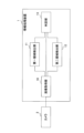
- FIG. 1 shows the configuration of an exemplary information processing device 1. As shown in FIG. This information processing apparatus 1 determines whether an image captured by the camera 2 is obtained by photographing the actual person or is obtained by photographing a displayed object of the person. conduct.
- the information processing device 1 includes an image acquisition section 10 , a first area detection section 11 , a second area detection section 12 and a determination section 13 .
- the image acquisition unit 10 acquires a plurality of images captured by the camera 2 at different times.
- the first area detection unit 11 detects an image area of a person's face in each of the multiple images acquired by the image acquisition unit 10 .
- Several techniques are known for detecting an image area of a person's face from a captured image.
- the first area detection unit 11 may use any of these methods, for example, the method proposed in Non-Patent Document 1 cited above.
- the second area detection unit 12 detects an image area having a shape that satisfies a predetermined condition from the remaining area outside the image area of the person's face in each of the plurality of images acquired by the image acquisition unit 10 .
- the determination unit 13 determines whether or not the face of the person represented in the plurality of images acquired by the image acquisition unit 10 is a display object. The determination unit 13 makes this determination based on the positional relationship between the image area of the face detected by the first area detection unit 11 and the image area having the above-described shape detected by the second area detection unit 12. This is done based on the state of change between images.
- This method is a method used by the second area detection unit 12 in the information processing apparatus 1 of FIG. 1 to detect a linear image area as an image area having a shape that satisfies a predetermined condition.
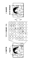
- an image example indicated as [A] is a photographed image obtained by photographing a photograph of a person's face (display object). Since the photo paper is easy to bend, the shape of the frame at the edge of the photo, which should be straight, is curved in this image example.
- an edge intensity map representing the edge intensity at the position of each pixel as the edge intensity of each pixel is generated from the captured image as an edge intensity image.
- [B] is an example of an edge strength image
- a partial region of the image [A] (part of the remaining region after excluding the face image region from the edge strength image of the captured image) ) of 7 pixels each in the vertical and horizontal directions (area including part of the frame).
- the edge strength value for each pixel is shown arranged at the position of each pixel.
- the pixels that make up the linear image area are selected. Note that, in the following description, the pixels forming the linear image area are referred to as "specific pixels". The selection of this specific pixel is performed by the following procedure.
- the pixel with the highest edge strength among the pixels included in the first pixel row in the edge strength image is selected as the first specific pixel.
- the pixel with the highest edge strength is the pixel with the edge strength value of "50". be. Therefore, this pixel is selected as the first specific pixel.
- the position of the selected specific pixel is shaded.
- pixels adjacent to the specific pixels are selected from the pixel rows adjacent to the pixel row that was selected in the above-described selection of the specific pixels (the pixel rows that included the specific pixels). Then, the pixel with the maximum edge strength is selected as the next specific pixel.
- pixels having an edge strength value of "50" are identified from the first pixel row to be selected in the edge strength image of [B] in FIG. selected as pixels. Therefore, in this case, the pixel row adjacent to the pixel row to be selected in the selection of the specific pixel is the second pixel row. Of the pixels included in the second pixel row, the pixels adjacent to the specific pixel are three pixels whose edge strength values are "44", "67", and "38", respectively. Among these three adjacent pixels, the pixel with the highest edge strength is the pixel with the edge strength value of "67", so this pixel is selected as the next specific pixel.
- next specific pixel is selected in this manner, the above-described selection of the next specific pixel is repeated for each pixel column.
- the pixel row to be selected in the selection of the specific pixel is selected.
- the pixel column adjacent to is the pixel column of the third column.
- the pixels adjacent to the specific pixel are three pixels whose edge intensity values are "58", "40", and "27”, respectively.
- the pixel with the highest edge strength is the pixel with the edge strength value of "58", so this pixel is selected as the next specific pixel.
- the next specific pixels are repeatedly selected with the pixel columns of the 4th, 5th, 6th, and 7th columns as the selection targets.
- pixels having edge intensity values of "76", “64”, “51”, and “57” are selected as specific pixels from the respective pixel columns.
- a linear image area in the captured image is detected by detecting an image area formed by a group of specific pixels obtained by repeating selection of specific pixels in the edge intensity image.
- the values of the edge strength are "50,” “67,” and "58,” respectively, from the pixel columns of the first example to the seventh column in the edge strength image of [B] in FIG. , '76', '64', '51' and '57' are selected as specific pixels.
- a linear image area formed by a specific pixel group composed of these specific pixels is detected from the photographed image illustrated in [A] of FIG.
- the example image of [C] represents the result of detection of a linear image area performed on the example image of [A] with a dashed line.
- linear image areas are detected along the left frame and right frame of the edge of the photo of the person's face. This is because the linear image area is detected for each of the two split images obtained by splitting the image [A] into the left and right parts.
- a linear image area is detected from the image area of the captured image as described above.
- the linear image area may be referred to as "linear area”.
- This method is a method used by the determination unit 13 in the information processing apparatus 1 of FIG.
- the image example of [A] in FIG. 2 is a photographed image obtained by photographing a person's face (display object).
- the positional relationship between the image area of the person's face and the linear area (frame at the edge of the photograph) detected as described above is obtained by photographing at different times. It is assumed that changes between captured images are synchronous.
- the image example in FIG. 3 is an example of a photographed image obtained by photographing an actual person.
- This example image shows a wall as the background of the person.
- This wall contains a linear object, and this linear object is also reflected in the captured image.
- this method it is determined whether or not changes in the positional relationship between the image area of the person's face and the line-shaped area are synchronized between the images captured at different times. If it is determined in this determination that the changes in the positional relationship between the two are not synchronized, it is determined that the person's face included in the captured image is not a display object.
- the above determination may be performed based on the degree of motion vector similarity for each of the face image region and the linear region, which is calculated using a plurality of captured images captured at different times, for example.
- the linear region represents the contour of the displayed object (frame at the edge of the photograph, display device, etc.). may be performed. In this determination, when it is determined that the linear region represents the outline of the display object, it is determined that the human face is the display object. You may make it further improve the precision of the determination that it is.
- the outline of the display object has the following characteristics.
- the outline of the displayed object is clear in the captured image, and it is highly probable that the edge strength of the pixels forming the outline is high.
- the linear shape representing the contour of the display object is highly likely to be parallel or nearly perpendicular to the orientation of the person's face shown in the display object.
- the distance between the line shape representing the outline of the display object and the person's face represented in the display object is close.
- the linear region represents the outline of the displayed object. That is, for example, this determination may be made using the edge intensity at the position of each pixel forming the linear region (the edge intensity for each pixel included in the specific pixel group).
- the inclination of a straight line that approximates the linear area with respect to the line segment connecting the positions of the left and right eyes of the person represented in the face image area is used as an index representing the orientation of the linear area with respect to the orientation of the person's face.
- the slope of this approximation straight line may be used to make this determination.
- the distance between the approximate straight line and the position of the person's nose represented in the face image area is used as an index representing the distance between the linear area and the person's face, and the distance between the approximate straight line and the nose is determined.
- the distance between the positions may be used to make this determination.
- this determination may be made using any two of the edge strength, the slope of the approximate straight line, and the distance.
- this determination may be made using all three of the above-described edge strength, slope of the approximate straight line, and distance.
- the linear region is displayed using the edge intensity, the slope of the approximate straight line, and the distance.
- the accuracy of representing the outline of the object may be calculated. In this case, whether or not the linear region represents the outline of the display object may be determined based on the result of comparing the calculated accuracy with a predetermined accuracy threshold.
- the degree of certainty that the linear region represents the outline of the displayed object for example, the degree of certainty R calculated by calculating the following formula (1) may be used.
- ⁇ is the average value of edge intensities at the positions of the pixels that make up the linear region (the average value of edge intensities of the specific pixels that make up the specific pixel group).
- ⁇ is the slope of the approximate straight line for the linear area with respect to the line segment connecting the positions of the left and right eyes of the person represented in the face image area.
- d is the distance between the approximate straight line and the position of the person's nose represented in the face image area.
- ⁇ , ⁇ , and ⁇ are weighting constants determined according to the degree of importance with respect to the accuracy R for each value of ⁇ , ⁇ , and d, and appropriate values are obtained in advance through experiments, for example.
- formula (1) is used when the line shape representing the outline of the display object is nearly parallel to the direction of the face of the person represented on the display object, more specifically, when the value of the inclination ⁇ is ⁇ It is used when 45° ⁇ +45°.
- the value of the inclination ⁇ is -90° ⁇ - In the case of 45° or +45° ⁇ +90°, the following formula (2) is used as the formula for calculating the accuracy R.
- the information processing apparatus 1 of FIG. 1 may be configured by a combination of a computer and software.
- FIG. 4 shows an example of the hardware configuration of the computer 20.
- the computer 20 includes hardware such as a processor 21, a memory 22, a storage device 23, a reader 24, a communication interface 26, and an input/output interface 27 as components. These components are connected via a bus 28, and data can be exchanged between the components.
- the processor 21 may be, for example, a single processor or a multiprocessor and multicore.
- the processor 21 uses the memory 22 to execute, for example, a photographed image determination program describing the procedure of photographed image determination processing, which will be described later.
- the memory 22 is, for example, a semiconductor memory, and may include a RAM area and a ROM area.
- the storage device 23 is, for example, a hard disk, a semiconductor memory such as a flash memory, or an external storage device. Note that RAM is an abbreviation for Random Access Memory. Also, ROM is an abbreviation for Read Only Memory.
- the reading device 24 accesses the removable storage medium 25 according to instructions from the processor 21 .
- the removable storage medium 25 is, for example, a semiconductor device (USB memory, etc.), a medium for inputting/outputting information by magnetic action (magnetic disk, etc.), a medium for inputting/outputting information by optical action (CD-ROM, DVD, etc.).
- USB is an abbreviation for Universal Serial Bus.
- CD is an abbreviation for Compact Disc.
- DVD is an abbreviation for Digital Versatile Disk.
- the communication interface 26 transmits and receives data via a communication network (not shown) according to instructions from the processor 21, for example.
- the input/output interface 27 acquires various data such as the image data of the captured image sent from the camera 2 . Also, the input/output interface 27 outputs the result of the determination process, which will be described later, output from the processor 21 .
- a program executed by the processor 21 of the computer 20 is provided, for example, in the following form. (1) Pre-installed in the storage device 23 . (2) provided by the removable storage medium 25; (3) provided from a server such as a program server to the communication interface 26 via a communication network;
- the hardware configuration of the computer 20 is an example, and the embodiment is not limited to this.
- some or all of the functions of the functional units described above may be implemented as hardware such as FPGA and SoC.
- FPGA is an abbreviation for Field Programmable Gate Array.
- SoC is an abbreviation for System-on-a-chip.
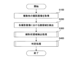
- FIG. 5 is a flow chart showing the details of this photographed image determination process.
- a process of acquiring a plurality of captured images is performed.
- a plurality of time-series images captured by the camera 2 at different times are acquired from the camera 2 via the input/output interface 27 and stored in the memory 22 .
- the processor 21 provides the function of the image acquisition unit 10 of FIG. 1 by executing the process of S100.
- processing is performed to detect an image area of a person's face in each of the plurality of images acquired by the processing of S100.
- the processor 21 provides the function of the first area detection unit 11 in FIG. 1 by executing the process of S200.
- the image area of the person's face which is the image area detected from the captured image by the process of S200, is sometimes referred to as a "face area”.
- This linear area detection process is a process of detecting a linear area from the remaining area outside the face area detected by the process of S200 in each of the plurality of images obtained by the process of S100. The details of this linear region detection processing will be described later.
- This determination process is a process of determining whether or not the face of a person represented in the plurality of images obtained by the process of S100 is a display object. This determination is made according to the method described above, based on the state of change between a plurality of images regarding the positional relationship between the face area and the realistic display area detected by the processing in S200 and S300. The details of this determination process will be described later.
- FIG. 6 is a flow chart showing the details of the linear area detection process.
- the processor 21 provides the function of the second area detection section 12 in FIG. 1 by executing this linear area detection process.
- this linear area detection process is a process that is executed for each of the plurality of captured images acquired by the process of S100 in FIG.
- Affine transformation for example, is known as a transformation process that rotates an image.
- affine transformation is used as a method of rotational transformation for a captured image.
- the positions of the left and right eyes are detected from the face area detected from the captured image by the process of S200 in FIG.
- the photographed image is rotationally transformed to horizontalize the line segment connecting the positions of the left and right eyes.
- the edges of the photographed image after this rotation conversion are trimmed so that the top and bottom sides are parallel to the above line segment, and the left and right sides are perpendicular to the above line segment.
- a process for generating a rectangular image is performed.
- the process of S310 is not performed, and the rectangular image is processed.
- the subsequent processing may be performed on the captured image.
- processing is performed to generate a plurality of edge strength images from the plurality of rectangular images generated in the processing of S310.
- the Laplacian filter among these methods is used to generate an edge strength image from a rectangular image.
- processing is performed to generate a residual edge strength image by excluding the region corresponding to the face region in the original captured image from the edge strength image generated by the processing of S320.
- the edge strength for each pixel included in the region corresponding to the face region in the original captured image is set to "0". of residual edge strength images are generated.
- vertical area detection processing is performed in S340, and horizontal area detection processing is performed in subsequent S350.
- Both of these are processes for detecting a linear region from a rectangular image according to the method described above using the residual edge intensity image generated by the process of S330.
- the vertical area detection process is for detecting a linear area in the vertical direction
- the horizontal area detection process is for detecting a linear area in the horizontal direction. Details of these processes will be described later.
- the processing up to this point is the linear region detection processing.
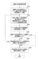
- FIG. 7 is a flow chart showing the details of vertical area detection processing.
- the pixel having the maximum edge strength among the pixels included in the uppermost pixel row in the residual edge strength image generated by the processing of S330 is selected as the first specific pixel. done.
- the position of the first specific pixel selected by this process becomes the starting point of the linear region.
- This process of S344 is for determining whether or not the edge intensity of the specific pixels selected by the process of S343 is of a level that can be regarded as a line area image area.
- the process proceeds to S345.
- the position of the specific pixel selected by the process of S343 is a line. It is regarded as the end of the shape area, and the process proceeds to S346.
- a process is performed to determine whether or not the pixel row including the specific pixels selected by the process of S343 is the lower pixel row in the residual edge intensity image generated by the process of S330.
- this determination processing when it is determined that the pixel row including the specific pixel is the bottom pixel row (when the determination result is YES), the position of the specific pixel selected by the processing of S343 is positioned in the linear area. The process proceeds to S346 assuming that it is the end.
- this determination process when it is determined that the pixel row including the specific pixel is not the pixel row at the bottom end (when the determination result is NO), the linear region may continue downward in the image. Therefore, the process returns to S342 and the above-described processes are repeated.
- the processing up to this point is the vertical region detection processing.
- the pixel row for which the first specific pixels are selected in the processing of S341 in the vertical region detection processing is the upper pixel row in the residual edge intensity image.
- the edge intensity image is generated from a rectangular image, and the upper edge of the rectangular image is parallel to the line segment connecting the positions of the left and right eyes in the face region. Therefore, the repetition of the processing from S342 to S345 is an example of repetition of the first selection when the first pixel row is parallel to the line segment, and the detection of the vertical linear region by the processing of S346 is This corresponds to detection of the first linear image area.
- FIG. 8 is a flow chart showing the details of horizontal area detection processing.
- a vertical linear area is searched from the top to the bottom of the image.
- the search is performed from left to right of the image.
- the pixel having the maximum edge strength among the pixels included in the leftmost pixel row in the residual edge strength image generated by the processing of S330 is selected as the first specific pixel. done.
- the position of the first specific pixel selected by this process becomes the starting point of the linear region.
- processing is performed to select, as the next specific pixel, the adjacent pixel with the highest edge strength among the adjacent pixels extracted by the processing of S352.
- the edge intensity of the specific pixel selected by the process of S353 is an edge intensity that can be regarded as the image area of the line area. It is for
- the process proceeds to S355.
- the position of the specific pixel selected by the process of S353 is a line. It is regarded as the end of the shape area, and the process proceeds to S356.
- processing is performed to determine whether the pixel row including the specific pixels selected by the processing of S353 is the rightmost pixel row in the residual edge intensity image generated by the processing of S330.
- this determination processing when it is determined that the pixel row including the specific pixel is the rightmost pixel row (when the determination result is YES), the position of the specific pixel selected by the processing of S353 is the position of the linear region. Assuming that it is the right end, the process proceeds to S356.
- this determination process when it is determined that the pixel row including the specific pixel is not the rightmost pixel row (when the determination result is NO), the linear region may continue to the right of the image. Therefore, the process returns to S352 and the above-described processes are repeated.
- the processing up to this point is the horizontal area detection processing.
- the pixel row for which the first specific pixels are selected in the process of S351 in this horizontal region detection process is the leftmost pixel row in the residual edge strength image.
- the edge strength image is generated from a rectangular image, and the left edge of the rectangular image is perpendicular to the line segment connecting the positions of the left and right eyes in the face region. Therefore, the repetition of the processing from S352 to S355 is an example of the repetition of the second selection when the first pixel row is perpendicular to the line segment, and the detection of the horizontal linear region by the processing of S356. corresponds to the detection of the second line-shaped image region.
- 9A and 9B are flowcharts showing the details of the determination process.
- the processor 21 provides the function of the determination unit 13 of FIG. 1 by executing this determination processing.
- Each of the processes from S401 to S405 shown in FIG. 9A performs the vertical linear area detected in the process of S340 in FIG. 6 and the horizontal linear area detected in the process of S350 in FIG. is performed for each of the
- a straight line approximating the linear area is obtained, and the positions of the left and right eyes of the person represented in the face area in the rectangular image are calculated for this approximate straight line.
- a process of calculating the inclination ⁇ with respect to the line segment connecting the is performed.
- the least-squares method is used to obtain the approximate straight line for the linear region from the positions of the constituent pixels of the linear region, but other methods may be used to obtain the approximate straight line.
- the two images are selected, for example, the images captured by the camera 2 consecutively in time series among the multiple images acquired by the process of S100 in FIG. Between these two images, there is no significant difference in the linear area representing the outer frame of the photograph or the linear object on the background wall.
- the average value ⁇ of edge strength, the slope ⁇ , and the distance d are considered to be close values. Therefore, the process of associating the two rectangular images with the linear regions in which these values are close to each other between the rectangular images of the two images is performed as the process of S404.
- a motion vector for the linear region associated by the processing in S404 is calculated based on the position of the linear region in each of the two rectangular images (for example, the barycentric position of the linear region). processing is performed.
- step S406 the motion vector for the face area in each of the two rectangular images is calculated as the position of the face area (for example, the nose of the person represented in the face area) in each of the two rectangular images. position).
- processing is performed to calculate the cosine similarity between the motion vector for the linear region and the motion vector for the face region.
- an average of motion vectors for linear regions in the vertical and horizontal directions is used as the motion vector for the linear region. Note that the motion vectors for the linear regions in the vertical direction and the horizontal direction are calculated by the processing of S405.
- the motion vector calculated by the process of S406 is used as the motion vector for the face area.
- processing is performed to determine whether the cosine similarity value calculated by the processing of S407 is equal to or greater than a predetermined similarity threshold.
- This determination process is for determining whether or not changes in the positional relationship between the linear area and the face area are synchronized. In this determination process, when it is determined that the value of the cosine similarity is equal to or greater than the similarity threshold (when the determination result is YES), changes in the positional relationship between the linear region and the face region are synchronized. It is judged that there is, and the process proceeds to S409.
- the linear region represents the outline of the display object using the average value ⁇ of the edge strength, the slope ⁇ , and the distance d calculated by the processing of S401 to S403.
- a process of calculating the accuracy R is performed.
- the above-described formula (2) is used to calculate the accuracy R for the linear area in the vertical direction
- the above-described formula (1) is used to calculate the accuracy R for the horizontal linear area. be done.
- a process of comparing the average value of the accuracy R for each linear area in the vertical direction and the horizontal direction with a predetermined accuracy threshold is performed. This processing is for determining whether or not the linear region represents the outline of the display object.
- this size comparison when it is determined that the average value of the accuracy R is equal to or greater than the accuracy threshold value (when the determination result is YES), it is determined that the linear region represents the contour of the displayed object, and the process proceeds to S411. Proceed with processing.
- this size comparison when it is determined that the average value of the accuracy R is smaller than the accuracy threshold (when the determination result is NO), it is determined that the linear region does not represent the outline of the displayed object, The process proceeds to S412.
- the above processing is the judgment processing.
- one vertical linear area is detected.
- the photographed image acquired by the processing of S100 in FIG. You may make it detect two.
- the photographed image obtained by the processing of S100 in FIG. Two areas may be detected.
- a vertical linear region may be detected that starts at the top of the image and ends at a position above the bottom of the image.
- the lower end of the image may be set as the starting end, and a vertical linear region extending upward from the starting end of the image may be further detected.
- the pixels of interest in the vertical area detection process of FIG. 7 may be selected sequentially upward from the pixel row at the bottom of the image. More specifically, when the determination result of S344 in FIG. 7 is NO, the processing similar to the processing of S341 to S346 may be performed.
- This similar process is different from the process of FIG. 7.
- the edge strength is the maximum. is selected as the first specific pixel.
- pixels adjacent to the specific pixel is extracted.
- a process of determining whether or not the pixel row including the specific pixels selected by the process of S343 is the top pixel row in the residual edge strength image generated by the process of S330 is performed.
- a horizontal linear area may be detected that starts at the left end of the image and ends at a position to the left of the right end of the image.
- the right end of the image may be set as the starting point, and a horizontal linear area extending from the starting point to the left of the image may be further detected.
- This similar process is different from the process of FIG. 7.
- the edge strength is the maximum. is selected as the first specific pixel.
- pixels adjacent to the specific pixel is extracted.
- a process of determining whether or not the pixel column including the specific pixels selected by the process of S353 is the leftmost pixel column in the residual edge intensity image generated by the process of S330 is performed.
Landscapes
- Engineering & Computer Science (AREA)
- Physics & Mathematics (AREA)
- General Physics & Mathematics (AREA)
- Theoretical Computer Science (AREA)
- Multimedia (AREA)
- Health & Medical Sciences (AREA)
- Oral & Maxillofacial Surgery (AREA)
- Human Computer Interaction (AREA)
- General Health & Medical Sciences (AREA)
- Computer Vision & Pattern Recognition (AREA)
- Image Analysis (AREA)
- Collating Specific Patterns (AREA)
Priority Applications (5)
| Application Number | Priority Date | Filing Date | Title |
|---|---|---|---|
| JP2023537789A JP7552913B2 (ja) | 2021-07-27 | 2021-07-27 | 判定方法、判定プログラム、及び情報処理装置 |
| EP21951796.8A EP4379652A4 (en) | 2021-07-27 | 2021-07-27 | DETERMINATION METHOD, DETERMINATION PROGRAM AND INFORMATION PROCESSING DEVICE |
| CN202180099659.5A CN117561551A (zh) | 2021-07-27 | 2021-07-27 | 判定方法、判定程序以及信息处理装置 |
| PCT/JP2021/027739 WO2023007586A1 (ja) | 2021-07-27 | 2021-07-27 | 判定方法、判定プログラム、及び情報処理装置 |
| US18/529,071 US20240104963A1 (en) | 2021-07-27 | 2023-12-05 | Determination method, determination program, and information processing apparatus |
Applications Claiming Priority (1)
| Application Number | Priority Date | Filing Date | Title |
|---|---|---|---|
| PCT/JP2021/027739 WO2023007586A1 (ja) | 2021-07-27 | 2021-07-27 | 判定方法、判定プログラム、及び情報処理装置 |
Related Child Applications (1)
| Application Number | Title | Priority Date | Filing Date |
|---|---|---|---|
| US18/529,071 Continuation US20240104963A1 (en) | 2021-07-27 | 2023-12-05 | Determination method, determination program, and information processing apparatus |
Publications (1)
| Publication Number | Publication Date |
|---|---|
| WO2023007586A1 true WO2023007586A1 (ja) | 2023-02-02 |
Family
ID=85086369
Family Applications (1)
| Application Number | Title | Priority Date | Filing Date |
|---|---|---|---|
| PCT/JP2021/027739 Ceased WO2023007586A1 (ja) | 2021-07-27 | 2021-07-27 | 判定方法、判定プログラム、及び情報処理装置 |
Country Status (5)
| Country | Link |
|---|---|
| US (1) | US20240104963A1 (https=) |
| EP (1) | EP4379652A4 (https=) |
| JP (1) | JP7552913B2 (https=) |
| CN (1) | CN117561551A (https=) |
| WO (1) | WO2023007586A1 (https=) |
Citations (6)
| Publication number | Priority date | Publication date | Assignee | Title |
|---|---|---|---|---|
| JP2006099614A (ja) | 2004-09-30 | 2006-04-13 | Toshiba Corp | 生体判別装置および生体判別方法 |
| JP2011009986A (ja) | 2009-06-25 | 2011-01-13 | Ricoh Co Ltd | 身分証明書撮影システム、身分証明書撮影方法およびプログラム |
| JP2014219703A (ja) | 2013-04-30 | 2014-11-20 | セコム株式会社 | 顔認証システム |
| JP2018169943A (ja) | 2017-03-30 | 2018-11-01 | パナソニックIpマネジメント株式会社 | 顔認証処理装置、顔認証処理方法及び顔認証処理システム |
| JP2019197426A (ja) | 2018-05-10 | 2019-11-14 | パナソニックIpマネジメント株式会社 | 顔認証装置、顔認証方法および顔認証システム |
| WO2020152917A1 (ja) * | 2019-01-23 | 2020-07-30 | Necソリューションイノベータ株式会社 | 顔認証装置、顔認証方法、プログラム、および記録媒体 |
Family Cites Families (2)
| Publication number | Priority date | Publication date | Assignee | Title |
|---|---|---|---|---|
| WO2016076914A1 (en) * | 2014-11-13 | 2016-05-19 | Intel Corporation | Facial liveness detection in image biometrics |
| US10990808B2 (en) * | 2016-02-09 | 2021-04-27 | Aware, Inc. | Face liveness detection using background/foreground motion analysis |
-
2021
- 2021-07-27 WO PCT/JP2021/027739 patent/WO2023007586A1/ja not_active Ceased
- 2021-07-27 EP EP21951796.8A patent/EP4379652A4/en active Pending
- 2021-07-27 JP JP2023537789A patent/JP7552913B2/ja active Active
- 2021-07-27 CN CN202180099659.5A patent/CN117561551A/zh active Pending
-
2023
- 2023-12-05 US US18/529,071 patent/US20240104963A1/en active Pending
Patent Citations (6)
| Publication number | Priority date | Publication date | Assignee | Title |
|---|---|---|---|---|
| JP2006099614A (ja) | 2004-09-30 | 2006-04-13 | Toshiba Corp | 生体判別装置および生体判別方法 |
| JP2011009986A (ja) | 2009-06-25 | 2011-01-13 | Ricoh Co Ltd | 身分証明書撮影システム、身分証明書撮影方法およびプログラム |
| JP2014219703A (ja) | 2013-04-30 | 2014-11-20 | セコム株式会社 | 顔認証システム |
| JP2018169943A (ja) | 2017-03-30 | 2018-11-01 | パナソニックIpマネジメント株式会社 | 顔認証処理装置、顔認証処理方法及び顔認証処理システム |
| JP2019197426A (ja) | 2018-05-10 | 2019-11-14 | パナソニックIpマネジメント株式会社 | 顔認証装置、顔認証方法および顔認証システム |
| WO2020152917A1 (ja) * | 2019-01-23 | 2020-07-30 | Necソリューションイノベータ株式会社 | 顔認証装置、顔認証方法、プログラム、および記録媒体 |
Non-Patent Citations (2)
| Title |
|---|
| KAIPENG ZHANG ET AL.: "Joint Face Detection and Alignment using Multi-task Cascaded Convolutional Networks & quot", IEEE SIGNAL PROCESSING LETTERS (SPL, vol. 23, October 2016 (2016-10-01), pages 1499 - 1503 |
| See also references of EP4379652A4 |
Also Published As
| Publication number | Publication date |
|---|---|
| EP4379652A4 (en) | 2024-07-31 |
| JPWO2023007586A1 (https=) | 2023-02-02 |
| CN117561551A (zh) | 2024-02-13 |
| JP7552913B2 (ja) | 2024-09-18 |
| US20240104963A1 (en) | 2024-03-28 |
| EP4379652A1 (en) | 2024-06-05 |
Similar Documents
| Publication | Publication Date | Title |
|---|---|---|
| US12014571B2 (en) | Method and apparatus with liveness verification | |
| EP4320606B1 (en) | Personalized biometric anti-spoofing protection using machine learning and enrollment data | |
| KR102455633B1 (ko) | 라이브니스 검사 방법 및 장치 | |
| CN106599772B (zh) | 活体验证方法和装置及身份认证方法和装置 | |
| JP7242528B2 (ja) | モバイルデバイスを用いてキャプチャした画像を使用する、指紋によるユーザ認証を実施するためのシステムおよび方法 | |
| US9424458B1 (en) | Systems and methods for performing fingerprint based user authentication using imagery captured using mobile devices | |
| CN104966079B (zh) | 区分真人面部与平坦表面 | |
| US7873189B2 (en) | Face recognition by dividing an image and evaluating a similarity vector with a support vector machine | |
| US20170262472A1 (en) | Systems and methods for recognition of faces e.g. from mobile-device-generated images of faces | |
| CN113614731B (zh) | 使用软生物特征的认证验证 | |
| EP2479707A1 (en) | Methods and systems of authentication | |
| JP2008117333A (ja) | 情報処理装置、情報処理方法、個人識別装置、個人識別装置における辞書データ生成・更新方法および辞書データ生成・更新プログラム | |
| EP2148303A1 (en) | Vein pattern management system, vein pattern registration device, vein pattern authentication device, vein pattern registration method, vein pattern authentication method, program, and vein data structure | |
| EP3642756A1 (en) | Detecting artificial facial images using facial landmarks | |
| CN107977559A (zh) | 一种身份认证方法、装置、设备和计算机可读存储介质 | |
| US11704937B2 (en) | Iris authentication device, iris authentication method and recording medium | |
| CN111460435A (zh) | 一种用户注册方法、验证方法和注册装置 | |
| KR20200127818A (ko) | 라이브니스 검사 방법 및 장치, 얼굴 인증 방법 및 장치 | |
| JP7415640B2 (ja) | 認証方法、情報処理装置、及び認証プログラム | |
| JP7552913B2 (ja) | 判定方法、判定プログラム、及び情報処理装置 | |
| JP2022040244A (ja) | 情報処理装置、方法およびプログラム | |
| JP7524980B2 (ja) | 判定方法、判定プログラム、及び情報処理装置 | |
| Phade et al. | Bio Tongue: A Tongue ID based Biometric Authentication System | |
| Deborah et al. | A Repository based Criminal Identification-Evolution in Forensics using Deep Learning | |
| Zahia et al. | Person Recognition and Authenticity Through Facial Analysis Combining LSTM and Siamese Networks |
Legal Events
| Date | Code | Title | Description |
|---|---|---|---|
| 121 | Ep: the epo has been informed by wipo that ep was designated in this application |
Ref document number: 21951796 Country of ref document: EP Kind code of ref document: A1 |
|
| WWE | Wipo information: entry into national phase |
Ref document number: 2023537789 Country of ref document: JP |
|
| WWE | Wipo information: entry into national phase |
Ref document number: 202180099659.5 Country of ref document: CN |
|
| WWE | Wipo information: entry into national phase |
Ref document number: 2021951796 Country of ref document: EP |
|
| NENP | Non-entry into the national phase |
Ref country code: DE |
|
| ENP | Entry into the national phase |
Ref document number: 2021951796 Country of ref document: EP Effective date: 20240227 |