WO2023002905A1 - Method for manufacturing cell culture container, and cell culture container - Google Patents
Method for manufacturing cell culture container, and cell culture container Download PDFInfo
- Publication number
- WO2023002905A1 WO2023002905A1 PCT/JP2022/027665 JP2022027665W WO2023002905A1 WO 2023002905 A1 WO2023002905 A1 WO 2023002905A1 JP 2022027665 W JP2022027665 W JP 2022027665W WO 2023002905 A1 WO2023002905 A1 WO 2023002905A1
- Authority
- WO
- WIPO (PCT)
- Prior art keywords
- cell culture
- container material
- culture vessel
- mold
- thin
- Prior art date
Links
- 238000004113 cell culture Methods 0.000 title claims abstract description 125
- 238000004519 manufacturing process Methods 0.000 title claims abstract description 78
- 238000000034 method Methods 0.000 title claims abstract description 74
- 238000003825 pressing Methods 0.000 claims abstract description 25
- 238000012258 culturing Methods 0.000 claims abstract 4
- 239000012611 container material Substances 0.000 claims description 160
- 230000002093 peripheral effect Effects 0.000 claims description 49
- 239000012779 reinforcing material Substances 0.000 claims description 25
- 239000000463 material Substances 0.000 claims description 21
- 238000012546 transfer Methods 0.000 claims description 19
- 238000001125 extrusion Methods 0.000 claims description 3
- 229920005992 thermoplastic resin Polymers 0.000 claims description 3
- 230000000052 comparative effect Effects 0.000 description 24
- 238000012360 testing method Methods 0.000 description 19
- PPBRXRYQALVLMV-UHFFFAOYSA-N Styrene Chemical compound C=CC1=CC=CC=C1 PPBRXRYQALVLMV-UHFFFAOYSA-N 0.000 description 16
- 238000010586 diagram Methods 0.000 description 16
- 239000002609 medium Substances 0.000 description 16
- 229920005989 resin Polymers 0.000 description 16
- 239000011347 resin Substances 0.000 description 16
- -1 polyethylene Polymers 0.000 description 11
- 239000012790 adhesive layer Substances 0.000 description 9
- 239000007788 liquid Substances 0.000 description 8
- 230000000694 effects Effects 0.000 description 6
- 229920000139 polyethylene terephthalate Polymers 0.000 description 6
- 239000005020 polyethylene terephthalate Substances 0.000 description 6
- 239000004698 Polyethylene Substances 0.000 description 5
- 229920000573 polyethylene Polymers 0.000 description 5
- VGGSQFUCUMXWEO-UHFFFAOYSA-N Ethene Chemical compound C=C VGGSQFUCUMXWEO-UHFFFAOYSA-N 0.000 description 4
- 239000005977 Ethylene Substances 0.000 description 4
- 239000003522 acrylic cement Substances 0.000 description 4
- 229910052782 aluminium Inorganic materials 0.000 description 4
- XAGFODPZIPBFFR-UHFFFAOYSA-N aluminium Chemical compound [Al] XAGFODPZIPBFFR-UHFFFAOYSA-N 0.000 description 4
- 239000001963 growth medium Substances 0.000 description 4
- 238000010438 heat treatment Methods 0.000 description 4
- 238000012986 modification Methods 0.000 description 4
- 230000004048 modification Effects 0.000 description 4
- 229920002725 thermoplastic elastomer Polymers 0.000 description 4
- 238000002474 experimental method Methods 0.000 description 3
- 229920000092 linear low density polyethylene Polymers 0.000 description 3
- 239000004707 linear low-density polyethylene Substances 0.000 description 3
- 229910052751 metal Inorganic materials 0.000 description 3
- 239000002184 metal Substances 0.000 description 3
- 229920000728 polyester Polymers 0.000 description 3
- 238000012545 processing Methods 0.000 description 3
- VSKJLJHPAFKHBX-UHFFFAOYSA-N 2-methylbuta-1,3-diene;styrene Chemical compound CC(=C)C=C.C=CC1=CC=CC=C1.C=CC1=CC=CC=C1 VSKJLJHPAFKHBX-UHFFFAOYSA-N 0.000 description 2
- KAKZBPTYRLMSJV-UHFFFAOYSA-N Butadiene Chemical compound C=CC=C KAKZBPTYRLMSJV-UHFFFAOYSA-N 0.000 description 2
- XUIMIQQOPSSXEZ-UHFFFAOYSA-N Silicon Chemical compound [Si] XUIMIQQOPSSXEZ-UHFFFAOYSA-N 0.000 description 2
- 238000001816 cooling Methods 0.000 description 2
- 229920001577 copolymer Polymers 0.000 description 2
- 238000005336 cracking Methods 0.000 description 2
- 229920001971 elastomer Polymers 0.000 description 2
- 239000000806 elastomer Substances 0.000 description 2
- 229920005672 polyolefin resin Polymers 0.000 description 2
- 238000011160 research Methods 0.000 description 2
- 229910052710 silicon Inorganic materials 0.000 description 2
- 239000010703 silicon Substances 0.000 description 2
- 238000003860 storage Methods 0.000 description 2
- SMZOUWXMTYCWNB-UHFFFAOYSA-N 2-(2-methoxy-5-methylphenyl)ethanamine Chemical compound COC1=CC=C(C)C=C1CCN SMZOUWXMTYCWNB-UHFFFAOYSA-N 0.000 description 1
- NIXOWILDQLNWCW-UHFFFAOYSA-N 2-Propenoic acid Natural products OC(=O)C=C NIXOWILDQLNWCW-UHFFFAOYSA-N 0.000 description 1
- 229920002126 Acrylic acid copolymer Polymers 0.000 description 1
- 239000004709 Chlorinated polyethylene Substances 0.000 description 1
- YCKRFDGAMUMZLT-UHFFFAOYSA-N Fluorine atom Chemical compound [F] YCKRFDGAMUMZLT-UHFFFAOYSA-N 0.000 description 1
- 239000005062 Polybutadiene Substances 0.000 description 1
- 239000004743 Polypropylene Substances 0.000 description 1
- XTXRWKRVRITETP-UHFFFAOYSA-N Vinyl acetate Chemical compound CC(=O)OC=C XTXRWKRVRITETP-UHFFFAOYSA-N 0.000 description 1
- BZHJMEDXRYGGRV-UHFFFAOYSA-N Vinyl chloride Chemical compound ClC=C BZHJMEDXRYGGRV-UHFFFAOYSA-N 0.000 description 1
- 230000001464 adherent effect Effects 0.000 description 1
- 239000000853 adhesive Substances 0.000 description 1
- 230000001070 adhesive effect Effects 0.000 description 1
- 230000004931 aggregating effect Effects 0.000 description 1
- 230000015572 biosynthetic process Effects 0.000 description 1
- 238000005520 cutting process Methods 0.000 description 1
- 239000003814 drug Substances 0.000 description 1
- HQQADJVZYDDRJT-UHFFFAOYSA-N ethene;prop-1-ene Chemical group C=C.CC=C HQQADJVZYDDRJT-UHFFFAOYSA-N 0.000 description 1
- 229920006242 ethylene acrylic acid copolymer Polymers 0.000 description 1
- 239000005038 ethylene vinyl acetate Substances 0.000 description 1
- 239000011737 fluorine Substances 0.000 description 1
- 229910052731 fluorine Inorganic materials 0.000 description 1
- 238000001415 gene therapy Methods 0.000 description 1
- 238000009169 immunotherapy Methods 0.000 description 1
- 229920000554 ionomer Polymers 0.000 description 1
- 239000004973 liquid crystal related substance Substances 0.000 description 1
- 229910021645 metal ion Inorganic materials 0.000 description 1
- 150000002739 metals Chemical class 0.000 description 1
- 229920003145 methacrylic acid copolymer Polymers 0.000 description 1
- 210000002220 organoid Anatomy 0.000 description 1
- 230000035699 permeability Effects 0.000 description 1
- 229920001200 poly(ethylene-vinyl acetate) Polymers 0.000 description 1
- 229920002857 polybutadiene Polymers 0.000 description 1
- 229920013716 polyethylene resin Polymers 0.000 description 1
- 229920000098 polyolefin Polymers 0.000 description 1
- 229920001155 polypropylene Polymers 0.000 description 1
- 229920001296 polysiloxane Polymers 0.000 description 1
- 229920002635 polyurethane Polymers 0.000 description 1
- 239000004814 polyurethane Substances 0.000 description 1
- 230000001172 regenerating effect Effects 0.000 description 1
- 230000007261 regionalization Effects 0.000 description 1
- 230000003014 reinforcing effect Effects 0.000 description 1
- 238000007789 sealing Methods 0.000 description 1
- 239000002210 silicon-based material Substances 0.000 description 1
- 229920002379 silicone rubber Polymers 0.000 description 1
- 239000000725 suspension Substances 0.000 description 1
- 125000000383 tetramethylene group Chemical group [H]C([H])([*:1])C([H])([H])C([H])([H])C([H])([H])[*:2] 0.000 description 1
- 229920001169 thermoplastic Polymers 0.000 description 1
- 239000004416 thermosoftening plastic Substances 0.000 description 1
- 210000001519 tissue Anatomy 0.000 description 1
- 239000004711 α-olefin Substances 0.000 description 1
Images


Classifications
-
- C—CHEMISTRY; METALLURGY
- C12—BIOCHEMISTRY; BEER; SPIRITS; WINE; VINEGAR; MICROBIOLOGY; ENZYMOLOGY; MUTATION OR GENETIC ENGINEERING
- C12M—APPARATUS FOR ENZYMOLOGY OR MICROBIOLOGY; APPARATUS FOR CULTURING MICROORGANISMS FOR PRODUCING BIOMASS, FOR GROWING CELLS OR FOR OBTAINING FERMENTATION OR METABOLIC PRODUCTS, i.e. BIOREACTORS OR FERMENTERS
- C12M23/00—Constructional details, e.g. recesses, hinges
- C12M23/02—Form or structure of the vessel
- C12M23/14—Bags
-
- C—CHEMISTRY; METALLURGY
- C12—BIOCHEMISTRY; BEER; SPIRITS; WINE; VINEGAR; MICROBIOLOGY; ENZYMOLOGY; MUTATION OR GENETIC ENGINEERING
- C12M—APPARATUS FOR ENZYMOLOGY OR MICROBIOLOGY; APPARATUS FOR CULTURING MICROORGANISMS FOR PRODUCING BIOMASS, FOR GROWING CELLS OR FOR OBTAINING FERMENTATION OR METABOLIC PRODUCTS, i.e. BIOREACTORS OR FERMENTERS
- C12M1/00—Apparatus for enzymology or microbiology
-
- C—CHEMISTRY; METALLURGY
- C12—BIOCHEMISTRY; BEER; SPIRITS; WINE; VINEGAR; MICROBIOLOGY; ENZYMOLOGY; MUTATION OR GENETIC ENGINEERING
- C12M—APPARATUS FOR ENZYMOLOGY OR MICROBIOLOGY; APPARATUS FOR CULTURING MICROORGANISMS FOR PRODUCING BIOMASS, FOR GROWING CELLS OR FOR OBTAINING FERMENTATION OR METABOLIC PRODUCTS, i.e. BIOREACTORS OR FERMENTERS
- C12M23/00—Constructional details, e.g. recesses, hinges
- C12M23/26—Constructional details, e.g. recesses, hinges flexible
-
- C—CHEMISTRY; METALLURGY
- C12—BIOCHEMISTRY; BEER; SPIRITS; WINE; VINEGAR; MICROBIOLOGY; ENZYMOLOGY; MUTATION OR GENETIC ENGINEERING
- C12M—APPARATUS FOR ENZYMOLOGY OR MICROBIOLOGY; APPARATUS FOR CULTURING MICROORGANISMS FOR PRODUCING BIOMASS, FOR GROWING CELLS OR FOR OBTAINING FERMENTATION OR METABOLIC PRODUCTS, i.e. BIOREACTORS OR FERMENTERS
- C12M25/00—Means for supporting, enclosing or fixing the microorganisms, e.g. immunocoatings
- C12M25/02—Membranes; Filters
-
- C—CHEMISTRY; METALLURGY
- C12—BIOCHEMISTRY; BEER; SPIRITS; WINE; VINEGAR; MICROBIOLOGY; ENZYMOLOGY; MUTATION OR GENETIC ENGINEERING
- C12M—APPARATUS FOR ENZYMOLOGY OR MICROBIOLOGY; APPARATUS FOR CULTURING MICROORGANISMS FOR PRODUCING BIOMASS, FOR GROWING CELLS OR FOR OBTAINING FERMENTATION OR METABOLIC PRODUCTS, i.e. BIOREACTORS OR FERMENTERS
- C12M3/00—Tissue, human, animal or plant cell, or virus culture apparatus
Definitions
- the present invention relates to cell culture technology, and in particular to a method for manufacturing a cell culture vessel having a fine uneven pattern structure on the culture surface.
- Methods for forming a fine uneven pattern structure on a culture surface generally include a thermal transfer method in which a plate-like or belt-like mold for forming an uneven pattern structure is pressed against the surface of a thermoplastic film and heated and pressurized, For example, there is a method in which a melted resin material is brought into contact with the surface of a cooling roll for forming an uneven pattern structure.
- these methods can be used to manufacture a cell culture vessel having a normal size culture surface, they cannot be easily applied to the manufacture of a cell culture vessel having a large size culture surface. was there.
- the problem of thinning the resin does not pose a problem as long as a certain amount of thickness is allowed, cracks can be prevented by increasing the thickness of the equipment. Since it is necessary to increase the gas permeability of the container wall, there is a demand to make the thickness of the equipment as thin as possible. Therefore, the risk of cracking has become a serious problem in the production of cell culture vessels.
- Patent Literature 1 discloses an endless belt-shaped metal mold capable of forming an uneven pattern structure on a large-sized culture surface.
- manufacturing such a belt-shaped mold is expensive, and there is a risk that the resin will be cut when the film having the concave-convex pattern structure formed thereon is peeled off from the mold.
- Patent Document 2 discloses a technique of arranging a plurality of molds side by side and transferring a fine pattern formed on the surface of the molds.
- this technique relates to a nano-order display element for manufacturing a large-screen liquid crystal display, and is pattern formation on a photocurable resin rather than thermal transfer.
- this mold is applied to thermal transfer, the resin flows into the gaps between the molds and protrusions are generated.
- the present inventors have made intensive research and have provided a primary mold with a convex portion for forming an uneven pattern structure on the surface of the container material and a convex portion for flattening a part of the surface of the container material.
- the present invention was completed by successfully solving the above problems by using a secondary mold.
- SUMMARY OF THE INVENTION The present invention has been made in view of the above circumstances, and aims to provide a method for manufacturing a cell culture vessel and a cell culture vessel having no projections or thin portions on the culture surface.
- the method for manufacturing a cell culture vessel of the present invention is a method for manufacturing a cell culture vessel having a cell culture surface, wherein the surface of the vessel material is provided with projections forming an uneven pattern structure.
- the primary mold and a secondary mold having a convex portion for flattening a part of the surface of the container material, the primary mold is pressed against the container material, and the container material is The uneven pattern structure is formed in the container material, the secondary mold is pressed against the thin portion formed in the container material, the thin portion is modified into a flattened portion, and the modified flattened portion
- the plurality of primary molds are arranged adjacently along a boundary line and pressed against the container material to form the uneven pattern structure on the container material. pressing the secondary mold against the projecting portions and the thin-walled portions formed at portions corresponding to the boundary lines of the plurality of primary molds in the container material, thereby flattening the projecting portions and the thin-walled portions; It is preferable to adopt a method of modifying the modified portion.
- the single primary mold is used to press the container material a plurality of times to form the uneven pattern structure on the container material. It is also preferable to adopt a method of pressing the secondary mold against the thin portion formed at a portion corresponding to the periphery of the primary mold to convert the thin portion into a flattened portion.
- the method for manufacturing a cell culture vessel of the present invention is a method of pressing the thin-walled portion and a predetermined region inside the thin-walled portion with the secondary mold. Further, in the method for producing a cell culture vessel of the present invention, the container material is adhered to a reinforcing material, and the primary mold and the secondary mold are attached to the surface of the container material opposite to the adhesion surface of the reinforcing material. It is also preferable to use a method of pressing the .
- the method for manufacturing a cell culture vessel of the present invention includes a method of pressing the primary mold and the secondary mold to form the concave-convex pattern structure and the flattened portion on the container material by thermal transfer or melt extrusion molding. It is also preferable to Further, in the method for manufacturing a cell culture vessel of the present invention, as the concave-convex pattern structure, a plurality of substantially triangular prisms are formed in parallel in a mountain range, or a plurality of concave portions with or without fine holes are formed. It is also preferable to set it as a method. Further, in the method for producing a cell culture vessel of the present invention, it is also preferable that the cell culture vessel is a bag-like vessel having a cell culture surface inside.
- the cell culture vessel of the present invention is a bag-like cell culture vessel having a cell culture surface inside, wherein the culture surface is provided with a plurality of areas having a concavo-convex pattern structure, and the concavo-convex pattern structure is A flattened portion is provided between the formed regions, and the flattened portion is provided along the entire periphery of the culture surface.
- the uneven pattern structure preferably has a plurality of substantially triangular prisms arranged in a mountain range, or a plurality of concave portions with or without fine holes.
- the present invention it is possible to provide a method for manufacturing a cell culture vessel and a cell culture vessel that do not have protrusions or thin portions on the culture surface.
- FIG. 4 is a schematic diagram showing steps of a method for manufacturing a cell culture vessel according to an embodiment of the present invention.
- FIG. 2 is a schematic diagram showing the state of the first step in the method for manufacturing the cell culture vessel according to the embodiment of the present invention.
- FIG. 4 is a schematic diagram showing how the first step and the second step of the method for manufacturing the cell culture vessel according to the embodiment of the present invention are performed by thermal transfer.
- FIG. 2 is a schematic diagram showing a state in which a primary mold is arranged in a container material and a secondary mold in the method for manufacturing a cell culture vessel according to an embodiment of the present invention.
- FIG. 5 is a schematic diagram showing a modification of the arrangement of the primary mold and the secondary mold in the method for manufacturing the cell culture vessel according to the embodiment of the present invention.
- FIG. 2 is a schematic diagram showing a primary mold and a reference example thereof in the method for manufacturing a cell culture vessel according to the embodiment of the present invention;
- FIG. 3 is a schematic diagram showing a reference example of a secondary mold in the method for manufacturing a cell culture vessel according to the embodiment of the present invention;
- FIG. 4 is a diagram showing the results of Test 1 for the method for manufacturing a cell culture vessel according to the embodiment of the present invention;
- FIG. 4 is a diagram showing the results of Test 2 on the method for manufacturing a cell culture vessel according to the embodiment of the present invention;
- FIG. 10 is a photograph showing a projecting portion and a thin portion of a container material obtained in Comparative Example 3 in Test 3 of the method for manufacturing a cell culture container according to the embodiment of the present invention.
- FIG. 11 is a diagram showing photographs of a flattened portion with a modified protrusion and a flattened portion with a modified thin-walled portion obtained in Example 3 in Test 3 of the method for manufacturing a cell culture vessel according to an embodiment of the present invention; be.
- FIG. 4 is a diagram showing the results of Test 3 on the method for manufacturing a cell culture vessel according to the embodiment of the present invention;
- the method for manufacturing a cell culture vessel according to the present embodiment is a method for manufacturing a cell culture vessel having a cell culture surface. As shown in FIG. and a secondary mold 20 with projections (21, 22) for flattening a part of the surface of the container material 30 are used. Further, the method for manufacturing a cell culture vessel of the present embodiment has a first step of pressing the primary mold 10 against the container material 30 to form the uneven pattern structure 31 on the container material 30 .
- the secondary mold 20 is pressed against the thin portion 33 formed in the container material 30 in the first step, and the thin portion 33 is flattened into the flattened portion 35. It has a second step of modifying.
- a cell culture vessel is formed by using the surface of the container material 30 including at least a part of the modified flattened portion 35 and the concave-convex pattern structure 31 as a culture surface. do.
- the flattened portion means a surface that does not have an uneven pattern structure, does not mean that it is completely flat, and includes cases where there is a curve.
- the convex part 11 of the primary mold 10 may be any structure as long as it can form a concave-convex pattern structure on the container material 30, and as shown in FIG. may be called.).
- the primary mold 10 is shown as a cross-sectional view at the center in the depth direction as seen from the front side, and the convex portion 11 is formed in the shape of a triangular prism in the depth direction.
- a plurality of primary molds 10 are arranged adjacent to each other along the boundary line and pressed against the container material 30, and the container material 30 has a concavo-convex pattern structure. 31 is preferably formed.
- the secondary mold 20 is formed on the projecting portion 32 and the thin portion 33 formed at the portion corresponding to the boundary line of the plurality of primary molds 10 in the container material 30. is preferably pressed to change the protruding portion 32 and the thinned portion 33 into flattened portions (34, 35).
- the method for manufacturing a cell culture vessel of the present embodiment in the first step, one primary mold 10 is used to press the container material 30 multiple times to form the uneven pattern structure 31 on the container material 30. It is also preferable to In addition, the method for manufacturing a cell culture vessel of the present embodiment includes a thin-walled portion formed at a portion corresponding to the peripheral portion of the primary mold 10 in the container material 30 (including a thin-walled portion formed at a portion corresponding to the boundary line). ) to convert the thinned portions into flattened portions (34, 35).
- the primary mold 10 and the secondary mold 20 are molds made of metal or silicon, for example. It was made using In this specification and claims, molds made of materials other than metals are also collectively referred to as molds.
- a polyethylene sheet having a thickness of 0.1 mm, for example, can be used as the container material 30 .
- a resin film or the like can be suitably used, and a polyolefin resin such as polyethylene or polypropylene can be used.
- a polyolefin resin such as polyethylene or polypropylene
- examples thereof include polyethylene, copolymers of ethylene and ⁇ -olefin, copolymers of ethylene and vinyl acetate, and ionomers using ethylene, acrylic acid or methacrylic acid copolymers, and metal ions.
- Polyolefin, styrene-based elastomer, polyester-based thermoplastic elastomer, and the like can also be used.
- soft vinyl chloride resin polybutadiene resin, ethylene-vinyl acetate copolymer, chlorinated polyethylene resin, polyurethane thermoplastic elastomer, polyester thermoplastic elastomer, silicone thermoplastic elastomer, styrene elastomer, such as SBS (styrene ⁇ Butadiene/styrene), SIS (styrene/isoprene/styrene), SEBS (styrene/ethylene/butylene/styrene), SEPS (styrene/ethylene/propylene/styrene), polyolefin resin, fluorine-based resin, and the like may be used.
- SBS styrene ⁇ Butadiene/styrene
- SIS styrene/isoprene/styrene
- SEBS styrene/ethylene/butylene/styrene
- SEPS sty
- FIG. 2 shows an example of the arrangement of the primary mold 10 and the container material 30 in the first step.
- two primary molds 10 are placed on a container material 30, and by pressing the primary molds 10 against the container material 30, an uneven pattern structure 31 is formed on the surface of the container material 30. It is designed to be At this time, the portion of the container material 30 corresponding to the boundary line between the two primary molds 10 is often formed with a projecting portion 32 as a result of the resin flowing into a slight gap between the primary molds 10 .
- resin flows out of the primary mold 10, and as a result, a thin portion 33 is often formed in which the thickness of the container material 30 is reduced.
- these projecting portion 32 and thin portion 33 are modified into flattened portions (border flattened portion 34, peripheral flattened portion 35) using the secondary mold 20. By doing so, it is possible to manufacture a cell culture vessel without the protruding portion 32 and the thin portion 33, thereby solving these problems.
- a flattened portion is formed in the cell culture vessel, and a part of the uneven pattern structure 31 is crushed. It is a minor loss and poses no particular problem in cell culture.
- the container material 30 by bonding it to a reinforcing material. That is, it is preferable to bond the container material 30 to the reinforcing material, and press the primary mold 10 and the secondary mold 20 against the surface of the container material 30 opposite to the bonding surface of the reinforcing material.
- the primary mold 10 and the secondary mold 20 By bonding the container material 30 to the reinforcing material in this way, the protruding part 32 and the thin part 33 formed on the container material 30 by the primary mold 10 are stably flattened by the secondary mold 20. It is possible to change the part.
- this reinforcing material has an adhesive layer, and it is preferable that the container material 30 is adhered and fixed to this adhesive layer.
- simply stacking the container material 30 on the reinforcing material does not have the effect of stably changing the protrusion 32 and the thin-walled portion 33 formed on the container material 30 into flattened portions by the secondary mold 20 .
- such an effect can be sufficiently obtained by firmly attaching to a reinforcing material having an adhesive layer and being harder than the container material 30 (polyethylene or the like).
- the adhesive layer makes it possible to easily peel off the reinforcing material.
- the material for the reinforcing member is not particularly limited, polyester-based materials are suitable, and it is preferable to use polyethylene terephthalate (PET), which is harder than polyethylene, readily available and inexpensive.
- PET polyethylene terephthalate
- an acrylic adhesive material can be suitably used as a material for the adhesive layer.
- thermoplastic resin as described above as the material of the container material 30, and the formation of the uneven pattern structure 31 in the container material 30 by pressing the primary mold 10 is performed by thermal transfer or melt extrusion molding. preferably performed by
- a thermal transfer device 40 as shown in FIG. 3 can be used. That is, a cushioning material 50 (such as silicon rubber) is provided on the base plate 41, and the container 30 having a reinforcing material 60 (polyethylene terephthalate, etc.) having an adhesive layer adhered to the lower surface is placed on the cushioning material 50. Then, a plurality of primary molds 10 are arranged on the upper surface of the container material 30, and the primary molds 10 are heated while pressing the heating plate 43 against the primary molds 10 using the pressurizing cylinders 42. One step can be performed.
- a cushioning material 50 such as silicon rubber
- the container 30 having a reinforcing material 60 polyethylene terephthalate, etc.
- the primary mold 10 is removed from the upper surface of the container material 30 and the secondary mold 20 is attached to the lower surface of the heating plate 43 .
- the boundary protrusion 21 of the secondary mold 20 is positioned above the protrusion 32 formed on the container material 30, and the peripheral edge protrusion 22 of the secondary mold 20 is formed on the container material 30.
- the secondary mold 20 is arranged so as to be positioned above the thinned portion 33 .
- the second step can be performed by heating the container material 30 while pressing the secondary mold 20 arranged on the heating plate 43 against the container material 30 using the pressurizing cylinder 42 .
- the shape of the uneven pattern structure 31 formed on the container material 30 is not particularly limited as long as it is an uneven pattern.
- a plurality of such triangular prisms can be arranged in parallel in a mountain range (V pattern).
- the container material 30 is shown as a cross-sectional view at the center in the depth direction as seen from the front side, and the concave-convex pattern structure 31 is formed in a triangular prism shape in the depth direction.
- the concave-convex pattern structure 31 formed on the container material 30 may have a shape other than the V pattern described above, for example, a plurality of triangular prisms may be arranged side by side in the shape of a mountain range at intervals. Also, a plurality of recesses (wells) may be formed, and the recess may be hemispherical, conical, polygonal pyramidal, or the like, and the shape of the recess is not particularly limited. Furthermore, the bottom of the recess may or may not have fine holes.
- FIG. 4(a) shows a state in which two primary molds 10 are arranged in the container material 30, and FIG. 4(b) is a schematic diagram showing the structure of the secondary mold 20 used in this case.
- the upper side shows a plan view, and the lower side shows a front view.
- two primary molds 10 are arranged on the container material 30 and the primary molds 10 are pressed against the container material 30 to form the uneven pattern structure 31 on the container material 30 .
- a projecting portion 32 is formed at a portion of the container material 30 corresponding to the boundary line of the primary mold 10 .
- a thin portion 33 is formed at a portion of the container material 30 corresponding to the peripheral portion of the primary mold 10 excluding the boundary line.
- the secondary mold 20 includes a boundary convex portion 21 for pressing the protruding portion 32 to transform it into a flattened boundary portion 34, and a peripheral edge for pressing a thin portion 33 to transform it into a flattened peripheral portion 35. It has projections 22 and support portions 23 that support them.
- the boundary convex portion 21 and the peripheral convex portion 22 have the same height from the bottom surface of the support portion 23 .
- FIG. 4(a) by repeatedly pressing with one primary mold 10 without using two primary molds 10, an uneven pattern structure 31 is formed on the container material 30.
- a thin portion 33 is formed in a portion of the container material 30 corresponding to the boundary line of the repeatedly used primary mold 10, and corresponds to the peripheral edge portion of the container material 30 excluding the boundary line of the primary mold 10.
- a thin portion 33 is also formed in the portion.
- the peripheral convex portion 22 is formed with a wide width so that it can be pressed to a predetermined region inside the thin portion 33. 33 and a predetermined area inside the thin portion 33 are preferably pressed.
- the reason for this is that when a bag-like container having a cell culture surface inside is formed as a cell culture container, the periphery of the culture surface can be heat-sealed (thermally welded) so as to prevent liquid leakage.
- the V pattern forming surface needs to be the inner surface of the bag. For this reason, since the V-pattern forming surface is located on the opposite surface of the container material 30 to the heat sealer, heat is not transmitted efficiently and it is difficult to completely weld them. If the temperature of the heat sealer is increased until the V pattern forming surface is completely softened (welded), it is possible to completely weld the V pattern (the V pattern disappears). The part in direct contact is too hot and burns (carbonizes), which is not preferable.
- the predetermined area to be heat-sealed in order to form the container material 30 into a bag shape is also changed in advance into a flattened portion by the secondary mold 20. It is possible to perform heat sealing suitably.
- FIG. 5(a) shows a state in which four primary molds 10 are arranged in a container material 30, and FIG. 5(b) is a schematic diagram showing the structure of a secondary mold 20b used in this case, The upper side shows a plan view, and the lower side shows a front view.
- FIG. 5(a) four primary molds 10 are arranged on the container material 30, and the primary molds 10 are pressed against the container material 30, thereby forming the concave-convex pattern structure 31 on the container material 30.
- a projecting portion 32 is formed at a portion of the container material 30 corresponding to the boundary line of the primary mold 10 .
- a thin portion 33 is formed at a portion of the container material 30 corresponding to the peripheral portion of the primary mold 10 excluding the boundary line.
- a secondary mold 20b having a boundary convex portion 21b and a peripheral convex portion 22b is used to form a container material 30 having a projecting portion 32 and a thin portion 33.
- the container material 30 without the projecting portion 32 and the thin portion 33 can be obtained.
- the secondary mold 20b includes a boundary convex portion 21b for pressing the protruding portion 32 to transform it into a flattened boundary portion 34, and a peripheral edge for pressing the thin portion 33 to transform it into a flattened peripheral portion 35. It has projections 22b and support portions 23b that support them.
- the boundary convex portion 21b and the peripheral convex portion 22b have the same height from the bottom surface of the support portion 23b.
- the concave-convex pattern structure 31 is formed on the container material 30 .
- a thin portion 33 is formed in a portion of the container material 30 corresponding to the boundary line of the repeatedly used primary mold 10, and corresponds to the peripheral edge portion of the container material 30 excluding the boundary line of the primary mold 10.
- a thin portion 33 is also formed in the portion.
- the thin portion can be obtained by using the secondary mold 20b provided with the boundary convex portion 21b and the peripheral edge convex portion 22b shown in FIG. 5(b).
- 33 can be modified into a flattened portion. That is, the boundary convex portion 21b changes the thin portion 33 formed in the portion corresponding to the boundary line of the primary mold 10 to the boundary flattened portion 34, and the peripheral convex portion 22b changes the peripheral edge portion of the primary mold 10. It is possible to modify the formed thinned portion 33 into a peripheral flattened portion 35 .
- the container material 30 As a method of forming a cell culture vessel using the surface of the container material 30 including the flattened portions 34 and 35 and the uneven pattern structure 31 as a culture surface, for example, the container material Two containers 30 can be prepared, and the container materials 30 can be overlapped so that the culture surface faces inside, and the periphery can be heat-sealed. It is also possible to prepare one container material 30 and one sheet of resin film without a culture surface, stack them so that the culture surface faces inside, and heat-seal the periphery.
- the method of forming the cell culture vessel is not particularly limited as long as the surface of the vessel material 30 including the flattened portion and the uneven pattern structure 31 described above can be used as the culture surface.
- FIG. 6A shows a primary mold 10 used in the method for manufacturing a cell culture vessel of the present embodiment, and the primary mold 10 in the container material 30 by pressing the primary mold 10 against the container material 30. It shows how a thin portion 33 is formed at a portion corresponding to the peripheral portion.
- the present inventors Prior to the completion of the present invention, the present inventors cut the convex portion 110 on the peripheral edge of the primary mold 100 and pressed the primary mold 100 against the container material 30, as shown in FIG. 6(b). By doing so, the thickness of the portion of the container material 30 corresponding to the peripheral edge portion of the primary mold 10 is increased, and an experiment was conducted to see if the thin portion 33 could be prevented from being formed.
- the primary mold 100 in which the protrusion 110 on the peripheral edge is cut is used, the resin flows out from the peripheral edge of the primary mold 10 when the container material 30 is pressed, and as a result, the thin portion 33 is formed. found to be formed. Therefore, after research, the inventors of the present invention used a combination of the primary mold 10 and the secondary mold 20, and modified the thin-walled portion 33 into a flattened portion with the secondary mold 20, so that the primary mold 10 This has solved the problem that the thin portion 33 is formed at the portion corresponding to the peripheral portion of the . Even when such a primary mold 100 is used, it is possible to use the primary mold 100 in this embodiment because the thin-walled portion can be eliminated by using the secondary mold 20. be.
- FIG. 7 is a schematic diagram showing the configuration of the secondary mold 200 having the boundary convex portion 210 and not having the peripheral convex portion.
- the cell culture vessel of the present embodiment is obtained by the method for manufacturing a cell culture vessel described above, and is a bag-like cell culture vessel having a cell culture surface inside, wherein the culture surface has an uneven pattern structure 31.
- a flattened portion 34 is provided between the plurality of regions in which the concave-convex pattern structure 31 is formed, and a flattened portion 35 is provided along the entire periphery of the culture surface. characterized by
- the shape of the uneven pattern structure 31 is not particularly limited as long as it is an uneven pattern.
- a plurality of triangular prisms may be arranged side by side in the shape of a mountain range at intervals.
- a plurality of recesses (wells) may be formed, and the recesses may or may not have fine holes at the bottom.
- Cells to be cultured using the cell culture vessel of the present embodiment are not particularly limited, and may be suspension cells, adherent cells, spheres (cell clusters), or organoids prepared by aggregating several types of cells. .
- the uneven pattern is formed on the container material. Even if the structure is formed, by using a secondary mold, it is possible to obtain a container material without protrusions or thin-walled parts, which makes it difficult for cracks to occur and facilitates feeding of the culture medium. , it is possible to obtain a cell culture vessel capable of reducing the amount of medium used.
- Tests conducted to confirm the effects of the cell culture vessel manufacturing method according to the embodiment of the present invention will be described below.
- Tests conducted to confirm the effects of the cell culture vessel manufacturing method according to the embodiment of the present invention will be described below.
- Test 1 In this test, two primary molds are used simultaneously to form a concavo-convex pattern structure on the container material, and then the secondary mold is used to modify the protrusions and thin-walled portions formed on the container material into flattened parts. I did an experiment.
- the primary mold and the secondary mold used in this test were produced.
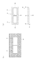
- a silicon (Si) material of 120 ⁇ 90 mm is used, dicing is performed with a blade having an angle of 75 degrees with the horizontal, and a plurality of primary molds such as the primary mold 10 in the schematic diagram of FIG. Triangular prisms were formed in parallel in the longitudinal direction of the same silicon material in the shape of a mountain range (hereinafter sometimes referred to as a V pattern).
- the primary mold 10 is shown as a cross-sectional view at the center in the depth direction as seen from the front side, and the plurality of convex portions 11 of the primary mold 10 are formed in the shape of a triangular prism in the depth direction. .
- a plurality of protrusions in the primary mold were formed continuously without gaps, and the pitch (the width of the base of one protrusion portion) was 0.11 mm. Also, the height of the convex portion (the height from the base to the vertex of the convex portion) was 0.2 mm.
- the secondary mold we created a mold that can be modified into a flattened portion by protruding portions and thin portions formed when two primary molds are arranged adjacent to each other in the longitudinal direction. Specifically, using an aluminum material of 180 ⁇ 120, a rectangular parallelepiped boundary protrusion 21 like the secondary mold 20 in the schematic diagram of FIG. 1 is produced in the lateral direction of the aluminum material. bottom. At this time, the boundary convex portion 21 was produced by cutting.
- the secondary mold 20 is shown as a cross-sectional view at the center in the depth direction viewed from the front side, and the boundary convex portion 21 of the secondary mold 20 is formed in the shape of a rectangular parallelepiped in the depth direction. ing.
- a peripheral protrusion 22 was formed on the peripheral edge of the secondary mold 20 .
- the peripheral convex portion 22 was formed around the entire periphery of the secondary mold 20 so as to be wider than the boundary convex portion 21 .
- the width of the boundary convex portion in the secondary mold was set to 2 mm, and the width of the peripheral edge convex portion 22 was set to 6 mm.
- the height of both the boundary convex portion and the peripheral edge convex portion was set to 5 mm.
- the width of the boundary convex portion was set to 2 mm in this test, the size is not particularly limited, and a narrower width is desirable from the viewpoint of reducing the area that crushes the uneven pattern structure 31 .
- the width of the boundary convex portion is too narrow, it becomes difficult to perform alignment for changing the protrusion 32 into a flattened portion.
- a linear low-density polyethylene film (manufactured by Toyo Seikan Group Holdings Co., Ltd.) with a thickness of 0.11 mm and a size of 200 x 140 mm was used as the container material.
- this container material was adhered to a reinforcing material made of polyethylene terephthalate using an acrylic adhesive. At this time, the thickness of the reinforcing material was 0.06 mm, and the thickness of the adhesive layer was 0.02 mm.
- two primary molds are arranged adjacent to each other in the longitudinal direction on the opposite side of the reinforcing material bonding surface of the container material, and a thermal transfer device (Toyo Seikan) is used. (manufactured by Group Holdings Co., Ltd.) was used to process an uneven pattern structure on the surface of the container material.
- the temperature of the primary mold was set to 130° C., and the two primary molds were pressurized at 4000 N for 20 seconds.
- Comparative Example 1 was a method of manufacturing a cell culture vessel using the surface of this container material as the culture surface of the cell culture vessel and using only this primary mold.
- protrusions were formed at sites corresponding to boundaries between adjacent primary molds.
- a thin portion was formed in the peripheral portion of the primary mold except for the boundary line. Photographs of these protrusions and thin-walled portions were taken from the side using a microscope, and the height of the protrusions from the bottom surface of the container and the thickness of the thin-walled portion of the container were measured.
- a secondary mold was attached to the thermal transfer device, and the secondary mold was pressed against the surface of the container material processed with the concave-convex pattern structure.
- the temperature of the secondary mold was set to 130° C., and a pressure of 4000 N was applied to the secondary mold for 20 seconds.
- the secondary mold was pressed against the projecting portion and the thin-walled portion formed at the portion corresponding to the boundary line of the adjacent primary molds, and the projecting portion and the thin-walled portion were changed into flattened portions.
- Example 1 was a method of manufacturing a cell culture vessel using a primary mold and a secondary mold. Then, a photograph is taken from the side surface of the flattened portion using a microscope, and the height of the flattened portion with the modified protrusion from the bottom surface of the container material and the thickness of the container material at the flattened portion with the modified thin-walled portion are determined. It was measured.
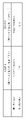
- Comparative Example 1 and Example 1 The results and effects of Comparative Example 1 and Example 1 are shown in FIG. As shown in the figure, the height of the projection in Comparative Example 1 was 0.3 to 0.8 mm, and the height of the highest portion of the projection was 0.8 mm. On the other hand, the height of the flattened portion in which the protruded portion was modified in Example 1 was 0.02 to 0.05 mm, and the height of the highest portion of the flattened portion was 0.05 mm. .
- Comparative Example 1 As described above, in Comparative Example 1, there is a protrusion on the culture surface, so there is a possibility that an obstacle may occur when the medium is fed. , it was clarified that the risk of failure occurring during medium feeding can be prevented.
- the minimum liquid thickness when the medium is discharged from the cell culture vessel is 0.8 mm in Comparative Example 1, but can be 0.05 mm in Example 1. It was clarified that the liquid thickness could be reduced and the medium consumption could be reduced.
- the thickness of the thin portion of Comparative Example 1 was 0.01 to 0.015 mm, and the thickness of the thinnest portion of the thin portion was 0.01 mm.
- the thickness of the flattened portion in which the thinned portion was modified in Example 1 was 0.025 to 0.03 mm, and the thickness of the thinnest portion of the flattened portion was 0.025 mm. That is, the container material obtained in Example 1 had no thin-walled portion, and cracks were less likely to occur than those obtained in Comparative Example 1.
- the same primary mold as in Test 1 was used.
- the secondary mold a mold was prepared in which the projecting portion and the thin-walled portion generated when two primary molds were arranged side by side in the lateral direction could be modified into flattened portions. Specifically, it was produced in the same manner as Test 1 using an aluminum material of 240 ⁇ 90.
- the width of the boundary convex portion in the secondary mold was set to 2 mm, and the width of the peripheral edge convex portion 22 was set to 6 mm.
- the height of both the boundary convex portion and the peripheral edge convex portion was set to 5 mm.
- a linear low-density polyethylene film (manufactured by Toyo Seikan Group Holdings Co., Ltd.) with a thickness of 0.11 mm and a size of 300 x 140 mm was used as the container material.
- this container material was adhered to a reinforcing material made of polyethylene terephthalate using an acrylic adhesive. At this time, the thickness of the reinforcing material was 0.06 mm, and the thickness of the adhesive layer was 0.02 mm.
- one primary mold is arranged at one position where two primary molds can be arranged adjacent to each other in the transverse direction on the opposite surface of the container material to the adhesive surface of the reinforcing material, Using a thermal transfer device (manufactured by Toyo Seikan Group Holdings Co., Ltd.), an uneven pattern structure was processed on the surface of the container material. At this time, the temperature of the primary mold was set to 130° C., and a pressure of 2000 N was applied to one primary mold for 20 seconds.
- Comparative Example 2 was a method of manufacturing a cell culture vessel using the surface of this vessel material as the culture surface of the cell culture vessel and using only this primary mold.
- a secondary mold was attached to the thermal transfer device, and the secondary mold was pressed against the surface of the container material processed with the concave-convex pattern structure.
- the temperature of the secondary mold was set to 130° C., and a pressure of 4000 N was applied to the secondary mold for 20 seconds.
- the secondary mold was pressed against the thin-walled portion to convert the thin-walled portion into a flattened portion.
- Example 2 A method for manufacturing a cell culture vessel using the surface of this container material as the culture surface of the cell culture vessel and using the primary mold and the secondary mold is referred to as Example 2. Then, a photograph was taken using a microscope from the side surface of the flattened portion, and the thickness of the container material in the flattened portion where the thin portion was modified was measured. In addition, the tensile strength of each of the container materials having the concave-convex pattern structure obtained in Comparative Example 2 and Example 2 was measured using a precision universal testing machine (Shimadzu Corporation, product number AG-IS). It was measured. At this time, the tension was applied in a direction parallel to the V pattern formed on the container material (transverse direction of the primary mold).
- Comparative Example 2 and Example 2 The results and effects of Comparative Example 2 and Example 2 are shown in FIG. As shown in the figure, the thickness of the thin portion of Comparative Example 2 was 0.008 to 0.012 mm, and the thickness of the thinnest portion of the thin portion was 0.008 mm. On the other hand, the height of the flattened portion where the thinned portion was modified was 0.022 to 0.028 mm, and the thickness of the thinnest portion of the flattened portion was 0.022 mm. Further, the tensile strength of the container material obtained in Comparative Example 2 was 2N, whereas the tensile strength of the container material obtained in Example 2 was 8N.
- Example 2 has a significantly reduced risk of cracking as compared to the container material obtained in Comparative Example 2, as a result of the modification of the thin-walled portion to the flattened portion. became clear.
- Test 3 In this test, four primary molds are used simultaneously to form a concavo-convex pattern structure on the container material, and then the secondary mold is used to modify the protrusions and thin portions formed on the container material into flattened parts. I did an experiment.
- the same primary mold as in Test 1 was used.
- the secondary mold as shown in FIG. 5, a mold was prepared in which the protruding portions and thin-walled portions generated when four primary molds were arranged adjacently could be changed into flattened portions. Specifically, it was produced in the same manner as in Test 1 using an aluminum material of 240 ⁇ 180.
- the width of the boundary convex portion in the secondary mold was set to 2 mm, and the width of the peripheral edge convex portion 22 was set to 6 mm.
- the height of both the boundary convex portion and the peripheral edge convex portion was set to 5 mm.
- a linear low-density polyethylene film (manufactured by Toyo Seikan Group Holdings Co., Ltd.) with a thickness of 0.11 mm and a size of 300 x 240 mm was used as the container material.
- this container material was adhered to a reinforcing material made of polyethylene terephthalate using an acrylic adhesive. At this time, the thickness of the reinforcing material was 0.06 mm, and the thickness of the adhesive layer was 0.02 mm.
- a secondary mold was attached to the thermal transfer device, and the secondary mold was pressed against the surface of the container material processed with the concave-convex pattern structure.
- the temperature of the secondary mold was set to 130° C., and the four primary molds were pressurized twice at 4000 N for 20 seconds.
- the secondary mold was pressed against the projecting portion and the thin-walled portion formed at the portion corresponding to the boundary line of the adjacent primary molds, and the projecting portion and the thin-walled portion were changed into flattened portions.
- Example 3 was a method of manufacturing a cell culture vessel using a primary mold and a secondary mold. Then, a photograph is taken from the side surface of the flattened portion using a microscope, and the height of the flattened portion with the modified protrusion from the bottom surface of the container material and the thickness of the container material at the flattened portion with the modified thin-walled portion are determined. It was measured.
- FIG. 11 shows a photograph of the flattened portion with modified protruding portion and the flattened portion with modified thin portion taken at this time.
- Comparative Example 3 and Example 3 The results and effects of Comparative Example 3 and Example 3 are shown in FIG. As shown in the figure, the height of the protrusion in Comparative Example 3 was 0.3 to 0.7 mm, and the height of the highest portion of the protrusion was 0.7 mm. In contrast, the height of the flattened portion with modified protrusions was 0.02 to 0.06 mm, and the height of the highest portion of the flattened portion was 0.06 mm.
- Comparative Example 3 there is a protrusion on the culture surface, so there is a possibility that an obstacle may occur when feeding the culture medium. , it was clarified that the risk of failure occurring during medium feeding can be prevented.
- the minimum liquid thickness when the medium is discharged from the cell culture vessel is 0.7 mm in Comparative Example 3, but can be 0.06 mm in Example 3. It was clarified that the liquid thickness could be reduced and the medium consumption could be reduced.
- the thickness of the thin portion of Comparative Example 3 was 0.009 to 0.013 mm, and the thickness of the thinnest portion of the thin portion was 0.009 mm.
- the height of the flattened portion in which the thinned portion was modified was 0.024 to 0.03 mm, and the thickness of the thinnest portion of the flattened portion of Example 3 was 0.024 mm. . That is, the container material obtained in Example 3 had no thin-walled portion, and cracks were less likely to occur than those obtained in Comparative Example 3.
- the present invention is not limited to the above embodiments and examples, and it goes without saying that various modifications can be made within the scope of the present invention.
- the number of primary molds used to form one culture surface is increased, such as 6 or 8, and the secondary mold is repeatedly pressed a plurality of times. It is possible to make appropriate changes, such as modifying the protruding portion or thin-walled portion of the container material into a flattened portion.
- the present invention can be suitably used when manufacturing a cell culture vessel having a large-sized culture surface.
Landscapes
- Health & Medical Sciences (AREA)
- Life Sciences & Earth Sciences (AREA)
- Engineering & Computer Science (AREA)
- Chemical & Material Sciences (AREA)
- Bioinformatics & Cheminformatics (AREA)
- Wood Science & Technology (AREA)
- Organic Chemistry (AREA)
- Zoology (AREA)
- Biotechnology (AREA)
- Biomedical Technology (AREA)
- Genetics & Genomics (AREA)
- Microbiology (AREA)
- Biochemistry (AREA)
- General Engineering & Computer Science (AREA)
- General Health & Medical Sciences (AREA)
- Sustainable Development (AREA)
- Clinical Laboratory Science (AREA)
- Immunology (AREA)
- Medicinal Chemistry (AREA)
- Cell Biology (AREA)
- Virology (AREA)
- Apparatus Associated With Microorganisms And Enzymes (AREA)
Abstract
Description
このような状況において、熱可塑性樹脂からなる袋状の細胞培養容器を用いて細胞を自動的に大量培養することが行われている。また、細胞培養容器の培養面に微細な凹凸パターン構造を形成することによって、培養効率を向上させることも提案されている。 In recent years, in fields such as pharmaceutical production, gene therapy, regenerative medicine, and immunotherapy, there has been a demand for efficient and large-scale culture of cells and tissues in an artificial environment.
Under such circumstances, cells are automatically cultured on a large scale using bag-like cell culture vessels made of thermoplastic resin. It has also been proposed to improve the culture efficiency by forming a fine uneven pattern structure on the culture surface of the cell culture vessel.
これらの方法は、通常サイズの培養面を有する細胞培養容器を製造する場合には利用可能であるものの、大判サイズの培養面を有する細胞培養容器を製造する場合には、容易に適用できないという問題があった。 Methods for forming a fine uneven pattern structure on a culture surface generally include a thermal transfer method in which a plate-like or belt-like mold for forming an uneven pattern structure is pressed against the surface of a thermoplastic film and heated and pressurized, For example, there is a method in which a melted resin material is brought into contact with the surface of a cooling roll for forming an uneven pattern structure.
Although these methods can be used to manufacture a cell culture vessel having a normal size culture surface, they cannot be easily applied to the manufacture of a cell culture vessel having a large size culture surface. was there.
しかしながら、このように分割して培養面を加工すると、金型の境目に軟化した樹脂が流れ込むことによって大きな突起が発生し、また金型の周縁部において樹脂が流れ出すため複数回に分けて使用した金型の間や金型の周縁部に対応する部位の樹脂が薄くなり、亀裂が発生し易くなるという問題が生じていた。 On the other hand, there is a method of processing the culture surface by dividing it by using multiple small molds side by side instead of using a single large mold, and using small molds in multiple batches. A method of processing the culture surface by dividing by
However, when the culture surface is divided and processed in this way, the softened resin flows into the boundary of the mold, resulting in large protrusions, and the resin flows out at the periphery of the mold. A problem has arisen in that the resin between the molds and the portions corresponding to the peripheral parts of the molds becomes thinner and cracks are more likely to occur.
本発明は、上記事情に鑑みてなされたものであり、培養面に突起部や薄肉部を有することのない細胞培養容器の製造方法、及び細胞培養容器の提供を目的とする。 Therefore, the present inventors have made intensive research and have provided a primary mold with a convex portion for forming an uneven pattern structure on the surface of the container material and a convex portion for flattening a part of the surface of the container material. The present invention was completed by successfully solving the above problems by using a secondary mold.
SUMMARY OF THE INVENTION The present invention has been made in view of the above circumstances, and aims to provide a method for manufacturing a cell culture vessel and a cell culture vessel having no projections or thin portions on the culture surface.
また、本発明の細胞培養容器の製造方法は、前記容器器材を補強材に接着し、前記容器器材における前記補強材の接着面の反対面に対して、前記一次金型と前記二次金型を押圧する方法とすることも好ましい。 Moreover, it is also preferable that the method for manufacturing a cell culture vessel of the present invention is a method of pressing the thin-walled portion and a predetermined region inside the thin-walled portion with the secondary mold.
Further, in the method for producing a cell culture vessel of the present invention, the container material is adhered to a reinforcing material, and the primary mold and the secondary mold are attached to the surface of the container material opposite to the adhesion surface of the reinforcing material. It is also preferable to use a method of pressing the .
また、本発明の細胞培養容器の製造方法は、前記凹凸パターン構造として、複数の略三角柱を山脈状に並列して形成し、又は、微細穴を有し若しくは有さない複数の凹部を形成する方法とすることも好ましい。
また、本発明の細胞培養容器の製造方法は、前記細胞培養容器が、内部に細胞の培養面を有する袋状の容器である方法とすることも好ましい。 Further, the method for manufacturing a cell culture vessel of the present invention includes a method of pressing the primary mold and the secondary mold to form the concave-convex pattern structure and the flattened portion on the container material by thermal transfer or melt extrusion molding. It is also preferable to
Further, in the method for manufacturing a cell culture vessel of the present invention, as the concave-convex pattern structure, a plurality of substantially triangular prisms are formed in parallel in a mountain range, or a plurality of concave portions with or without fine holes are formed. It is also preferable to set it as a method.
Further, in the method for producing a cell culture vessel of the present invention, it is also preferable that the cell culture vessel is a bag-like vessel having a cell culture surface inside.
また、本発明の細胞培養容器は、前記凹凸パターン構造が、複数の略三角柱が山脈状に並列し、又は、微細穴を有し若しくは有さない複数の凹部である構成とすることが好ましい。 The cell culture vessel of the present invention is a bag-like cell culture vessel having a cell culture surface inside, wherein the culture surface is provided with a plurality of areas having a concavo-convex pattern structure, and the concavo-convex pattern structure is A flattened portion is provided between the formed regions, and the flattened portion is provided along the entire periphery of the culture surface.
In the cell culture vessel of the present invention, the uneven pattern structure preferably has a plurality of substantially triangular prisms arranged in a mountain range, or a plurality of concave portions with or without fine holes.
また、本実施形態の細胞培養容器の製造方法は、容器器材30に対して一次金型10を押圧して、容器器材30に凹凸パターン構造31を形成する第一工程を有している。 The method for manufacturing a cell culture vessel according to the present embodiment is a method for manufacturing a cell culture vessel having a cell culture surface. As shown in FIG. and a
Further, the method for manufacturing a cell culture vessel of the present embodiment has a first step of pressing the
そして、本実施形態の細胞培養容器の製造方法は、改変された平坦化部35の少なくとも一部と形成された凹凸パターン構造31を含む容器器材30の表面を培養面として、細胞培養容器を形成する。 Furthermore, in the method for manufacturing a cell culture vessel of the present embodiment, the
In the method for manufacturing a cell culture vessel of the present embodiment, a cell culture vessel is formed by using the surface of the
また、一次金型10の凸部11は、容器器材30に凹凸パターン構造を形成できるものであればよく、図1に示すように複数の三角柱が山脈状に並列したもの(以下、Vパターンと称する場合がある。)であってもよい。なお、同図において、一次金型10は正面側から見た奥行き方向中央の断面図として表されており、凸部11は、奥行き方向に三角柱状に形成されている。 In the present specification and claims, the flattened portion means a surface that does not have an uneven pattern structure, does not mean that it is completely flat, and includes cases where there is a curve.
Moreover, the
また、本実施形態の細胞培養容器の製造方法は、容器器材30における複数の一次金型10の境界線に対応する部位に形成された突出部32と薄肉部33に対して二次金型20を押圧して、突出部32と薄肉部33を平坦化部(34,35)に改変することが好ましい。 In the method for manufacturing a cell culture vessel of the present embodiment, in the first step, a plurality of
In addition, in the method for manufacturing a cell culture vessel according to the present embodiment, the
また、本実施形態の細胞培養容器の製造方法は、容器器材30における一次金型10の周縁部に対応する部位に形成された薄肉部(境界線に対応する部位に形成された薄肉部を含む)に対して前記二次金型20を押圧して、薄肉部を平坦化部(34,35)に改変することも好ましい。 Furthermore, in the method for manufacturing a cell culture vessel of the present embodiment, in the first step, one
In addition, the method for manufacturing a cell culture vessel of the present embodiment includes a thin-walled portion formed at a portion corresponding to the peripheral portion of the
具体的には、容器器材30の材料としては、樹脂フィルムなどを好適に用いることができ、ポリエチレンやポリプロピレンなどのポリオレフィン系樹脂等を用いることができる。例えば、ポリエチレン、エチレンとα-オレフィンの共重合体、エチレンと酢酸ビニルの共重合体、エチレンとアクリル酸やメタクリル酸共重合体と金属イオンを用いたアイオノマー等を挙げることができる。また、ポリオレフィン、スチレン系エラストマー、ポリエステル系熱可塑性エラストマー等を用いることもできる。さらに、軟質塩化ビニル樹脂、ポリブタジエン樹脂、エチレン-酢酸ビニル共重合体、塩素化ポリエチレン樹脂、ポリウレタン系熱可塑性エラストマー、ポリエステル系熱可塑性エラストマー、シリコーン系熱可塑性エラストマー、スチレン系エラストマー、例えば、SBS(スチレン・ブタジエン・スチレン)、SIS(スチレン・イソプレン・スチレン)、SEBS(スチレン・エチレン・ブチレン・スチレン)、SEPS(スチレン・エチレン・プロピレン・スチレン)、ポリオレフィン樹脂、フッ素系樹脂等を用いてもよい。 A polyethylene sheet having a thickness of 0.1 mm, for example, can be used as the
Specifically, as the material of the
図2において、2個の一次金型10が容器器材30上に配置されており、一次金型10を容器器材30に対して押圧することによって、容器器材30の表面に凹凸パターン構造31が形成されるようになっている。
このとき、容器器材30における2個の一次金型10の境界線に対応する部位は、一次金型10間の僅かな隙間に樹脂が流れ込む結果、突出部32が形成されることが多くある。また、境界線を除く一次金型10の周縁部においては、樹脂が一次金型10の外側に流れ出る結果、容器器材30の厚みが薄くなる薄肉部33が形成されることが多くある。 FIG. 2 shows an example of the arrangement of the
In FIG. 2, two
At this time, the portion of the
また、薄肉部33が形成された容器器材30を用いて細胞培養容器を製造すると、薄肉部33において亀裂が生じやすく、培地の液漏れが発生するという問題がある。 When a cell culture vessel is manufactured using the
In addition, when a cell culture vessel is manufactured using the
このように容器器材30を補強材に接着して使用することによって、一次金型10によって容器器材30に形成された突出部32と薄肉部33を、二次金型20によって安定して平坦化部に改変することが可能になっている。 Moreover, in the method for manufacturing a cell culture vessel according to the present embodiment, it is preferable to use the
By bonding the
ここで、容器器材30を単純に補強材に重ねるだけでは、容器器材30に形成された突出部32と薄肉部33を二次金型20によって安定して平坦化部に改変する効果は小さい。一方、粘着層を有する、容器器材30(ポリエチレンなど)よりも硬い補強材にしっかり貼り付けることによって、このような効果を十分に得ることができる。 Moreover, it is preferable that this reinforcing material has an adhesive layer, and it is preferable that the
Here, simply stacking the
補強材の材料としては、特に限定されないが、ポリエステル系の材料が適しており、ポリエチレンよりも硬く、入手し易く低廉なポリエチレンテレフタレート(PET)を用いることが好ましい。また、粘着層の材料としては、例えばアクリル系粘着材を好適に用いることができる。 That is, by attaching the reinforcing material to the
Although the material for the reinforcing member is not particularly limited, polyester-based materials are suitable, and it is preferable to use polyethylene terephthalate (PET), which is harder than polyethylene, readily available and inexpensive. Moreover, as a material for the adhesive layer, for example, an acrylic adhesive material can be suitably used.
そして、加圧シリンダー42を用いて加熱プレート43に配置された二次金型20を容器器材30に対して押圧しつつ容器器材30を加熱することにより、第二工程を行うことができる。 Next, the
Then, the second step can be performed by heating the
すなわち、二次金型20は、突出部32を押圧して境界平坦化部34に改変するための境界凸部21と、薄肉部33を押圧して周縁平坦化部35に改変するための周縁凸部22と、これらを支持する支持部23を備えている。境界凸部21と周縁凸部22の支持部23の底面からの高さは同一である。 Therefore, in this embodiment, as shown in FIG. By pressing , the
That is, the
この場合、容器器材30における繰り返し用いた一次金型10の境界線に対応する部位には、薄肉部33が形成され、また容器器材30における一次金型10の境界線を除く周縁部に対応する部位にも、薄肉部33が形成される。 Further, in FIG. 4(a), by repeatedly pressing with one
In this case, a
すなわち、境界凸部21によって一次金型10の境界線に対応する部位に形成された薄肉部33を境界平坦化部34に改変すると共に、周縁凸部22によって、一次金型10の周縁部に形成された薄肉部33を周縁平坦化部35に改変することが可能である。 Even when the
That is, the
その理由は、細胞培養容器として内部に細胞の培養面を有する袋状の容器を形成する場合に、培養面の周囲を液漏れがないようにヒートシール(熱溶着)できるためである。 Furthermore, in the method for manufacturing a cell culture vessel according to the present embodiment, the peripheral
The reason for this is that when a bag-like container having a cell culture surface inside is formed as a cell culture container, the periphery of the culture surface can be heat-sealed (thermally welded) so as to prevent liquid leakage.
また、仮に、Vパターン形成面が完全に軟化(溶着)するまでヒートシーラーの温度を上げると、Vパターン部を完全に溶着させる(Vパターンは消滅する)ことは可能であるが、ヒートシーラーに直接接触している部分は温度が高すぎて焦げて(炭化)してしまうため、好ましくない。
そこで、本実施形態の細胞培養容器の製造方法では、容器器材30を袋状にするためにヒートシールを行う所定領域についても二次金型20によって予め平坦化部に改変しておくことによって、ヒートシールを好適に行うことを可能としている。 That is, when the
If the temperature of the heat sealer is increased until the V pattern forming surface is completely softened (welded), it is possible to completely weld the V pattern (the V pattern disappears). The part in direct contact is too hot and burns (carbonizes), which is not preferable.
Therefore, in the method for manufacturing a cell culture vessel according to the present embodiment, the predetermined area to be heat-sealed in order to form the
すなわち、二次金型20bは、突出部32を押圧して境界平坦化部34に改変するための境界凸部21bと、薄肉部33を押圧して周縁平坦化部35に改変するための周縁凸部22bと、これらを支持する支持部23bを備えている。境界凸部21bと周縁凸部22bの支持部23bの底面からの高さは同一である。 Therefore, in the present embodiment, as shown in FIG. 5B, a
That is, the
この場合、容器器材30における繰り返し用いた一次金型10の境界線に対応する部位には、薄肉部33が形成され、また容器器材30における一次金型10の境界線を除く周縁部に対応する部位にも、薄肉部33が形成される。 In addition, in FIG. 5( a ), by repeatedly pressing using one or two
In this case, a
すなわち、境界凸部21bによって一次金型10の境界線に対応する部位に形成された薄肉部33を境界平坦化部34に改変すると共に、周縁凸部22bによって、一次金型10の周縁部に形成された薄肉部33を周縁平坦化部35に改変することが可能である。 Even when the
That is, the boundary
また、容器器材30を1枚と培養面が形成されていない樹脂フィルムを1枚準備して、培養面が内側になるようにこれらを重ね合わせて、周囲をヒートシールすることもできる。
その他、細胞培養容器を形成する方法については、上述した平坦化部と凹凸パターン構造31を含む容器器材30の表面を培養面とすることができればよく、具体的な手段については特に限定されない。 In the method for manufacturing a cell culture vessel of the present embodiment, as a method of forming a cell culture vessel using the surface of the
It is also possible to prepare one
In addition, the method of forming the cell culture vessel is not particularly limited as long as the surface of the
図6(a)は、本実施形態の細胞培養容器の製造方法において用いられる一次金型10と、この一次金型10を容器器材30に押圧することによって、容器器材30における一次金型10の周縁部に対応する部位に薄肉部33が形成される様子を示している。 Here, with reference to FIG. 6, the primary mold and its reference example in the method for manufacturing the cell culture vessel of the present embodiment will be described.
FIG. 6A shows a
そこで、本発明者らは研究の末、一次金型10と二次金型20を組み合わせて使用し、二次金型20によって薄肉部33を平坦化部に改変することによって、一次金型10の周縁部に対応する部位に薄肉部33が形成される問題を解消するに至った。
なお、このような一次金型100を使用した場合にも、二次金型20を用いることによって、薄肉部を無くすことができるため、本実施形態において一次金型100を使用することは可能である。 However, even if the
Therefore, after research, the inventors of the present invention used a combination of the
Even when such a
図7は、境界凸部210を備え、周縁凸部を備えていない二次金型200の構成を示す模式図であり、上側が平面図を、下側が正面図を示している。 Next, referring to FIG. 7, a reference example of the secondary mold in the method for manufacturing the cell culture vessel of the present embodiment will be described.
FIG. 7 is a schematic diagram showing the configuration of the
そこで、本実施形態の細胞培養容器の製造方法においては、境界凸部21と共に周縁凸部22を備えた二次金型20を用いることによって、突出部32を安定的に平坦化部に改変することを可能としている。 Moreover, when such a
Therefore, in the method for manufacturing a cell culture vessel of the present embodiment, by using the
[試験1]
本試験では、2個の一次金型を同時に用いて容器器材に凹凸パターン構造を形成し、次いで二次金型を用いて容器器材に形成された突出部と薄肉部を平坦化部に改変する実験を行った。 Tests conducted to confirm the effects of the cell culture vessel manufacturing method according to the embodiment of the present invention will be described below.
[Test 1]
In this test, two primary molds are used simultaneously to form a concavo-convex pattern structure on the container material, and then the secondary mold is used to modify the protrusions and thin-walled portions formed on the container material into flattened parts. I did an experiment.
一次金型としては、120×90mmのシリコン(Si)材を使用して、水平との角度が75度のブレードによりダイシング加工を行い、図1の模式図における一次金型10のような複数の三角柱を同シリコン材の長手方向に山脈状に並列して形成したもの(以下、Vパターンと称する場合がある。)を作製した。なお、同図において、一次金型10は正面側から見た奥行き方向中央の断面図として表されており、一次金型10の複数の凸部11は、奥行き方向に三角柱状に形成されている。
一次金型における複数の凸部は、互いに隙間無く連続して形成されており、そのピッチ(1個の凸部部分の底辺の幅)は、0.11mmであった。また、同凸部の高さ(凸部部分の底辺から頂点までの高さ)は、0.2mmであった。 First, as the primary mold and the secondary mold used in this test, the following were produced.
As the primary mold, a silicon (Si) material of 120 × 90 mm is used, dicing is performed with a blade having an angle of 75 degrees with the horizontal, and a plurality of primary molds such as the
A plurality of protrusions in the primary mold were formed continuously without gaps, and the pitch (the width of the base of one protrusion portion) was 0.11 mm. Also, the height of the convex portion (the height from the base to the vertex of the convex portion) was 0.2 mm.
二次金型における境界凸部の幅を2mmとし、周縁凸部22の幅を6mmとした。また、境界凸部と周縁凸部の高さは、共に5mmとした。 Also, a
The width of the boundary convex portion in the secondary mold was set to 2 mm, and the width of the peripheral edge
そして、この容器器材の表面を細胞培養容器における培養面とし、この一次金型のみを使用した細胞培養容器の製造方法を比較例1とした。 Next, as shown in FIG. 4( a ), two primary molds are arranged adjacent to each other in the longitudinal direction on the opposite side of the reinforcing material bonding surface of the container material, and a thermal transfer device (Toyo Seikan) is used. (manufactured by Group Holdings Co., Ltd.) was used to process an uneven pattern structure on the surface of the container material. At this time, the temperature of the primary mold was set to 130° C., and the two primary molds were pressurized at 4000 N for 20 seconds.
Comparative Example 1 was a method of manufacturing a cell culture vessel using the surface of this container material as the culture surface of the cell culture vessel and using only this primary mold.
これによって、隣り合う一次金型の境界線に対応する部位に形成された突出部と薄肉部に対して二次金型を押圧して、突出部と薄肉部を平坦化部に改変した。 Next, a secondary mold was attached to the thermal transfer device, and the secondary mold was pressed against the surface of the container material processed with the concave-convex pattern structure. At this time, the temperature of the secondary mold was set to 130° C., and a pressure of 4000 N was applied to the secondary mold for 20 seconds.
As a result, the secondary mold was pressed against the projecting portion and the thin-walled portion formed at the portion corresponding to the boundary line of the adjacent primary molds, and the projecting portion and the thin-walled portion were changed into flattened portions.
同図に示されるように、比較例1の突出部の高さは、0.3~0.8mmであり、突出部の最高部の高さは、0.8mmであった。これに対して、実施例1における突出部が改変された平坦化部の高さは、0.02~0.05mmであり、平坦化部の最高部の高さは、0.05mmであった。 The results and effects of Comparative Example 1 and Example 1 are shown in FIG.
As shown in the figure, the height of the projection in Comparative Example 1 was 0.3 to 0.8 mm, and the height of the highest portion of the projection was 0.8 mm. On the other hand, the height of the flattened portion in which the protruded portion was modified in Example 1 was 0.02 to 0.05 mm, and the height of the highest portion of the flattened portion was 0.05 mm. .
また、細胞培養容器から培地を排出する時の最小液厚は、比較例1では0.8mmとなるが、実施例1では0.05mmとすることができるため、培地交換時に細胞培養容器内の液厚を小さくすることができ、培地の消費量を低減可能であることが明らかになった。 As described above, in Comparative Example 1, there is a protrusion on the culture surface, so there is a possibility that an obstacle may occur when the medium is fed. , it was clarified that the risk of failure occurring during medium feeding can be prevented.
In addition, the minimum liquid thickness when the medium is discharged from the cell culture vessel is 0.8 mm in Comparative Example 1, but can be 0.05 mm in Example 1. It was clarified that the liquid thickness could be reduced and the medium consumption could be reduced.
すなわち、実施例1によって得られた容器器材には薄肉部がなく、比較例1によって得られたものよりも亀裂が生じ難いものであった。 The thickness of the thin portion of Comparative Example 1 was 0.01 to 0.015 mm, and the thickness of the thinnest portion of the thin portion was 0.01 mm. On the other hand, the thickness of the flattened portion in which the thinned portion was modified in Example 1 was 0.025 to 0.03 mm, and the thickness of the thinnest portion of the flattened portion was 0.025 mm.
That is, the container material obtained in Example 1 had no thin-walled portion, and cracks were less likely to occur than those obtained in Comparative Example 1.
本試験では、1個の一次金型を2回繰り返し用いて容器器材に凹凸パターン構造を形成し、次いで二次金型を用いて容器器材に形成された薄肉部を平坦化部に改変する実験を行った。 [Test 2]
In this test, one primary mold was repeatedly used twice to form a concavo-convex pattern structure on the container material, and then a secondary mold was used to modify the thin part formed on the container material into a flattened part. did
二次金型としては、一次金型を短手方向に2個隣接して配置した場合に発生する突出部と薄肉部を平坦化部に改変可能なものを作製した。具体的には、240×90のアルミニウム材を使用して、試験1と同様の方法で作製した。
二次金型における境界凸部の幅を2mmとし、周縁凸部22の幅を6mmとした。また、境界凸部と周縁凸部の高さは、共に5mmとした。 The same primary mold as in
As the secondary mold, a mold was prepared in which the projecting portion and the thin-walled portion generated when two primary molds were arranged side by side in the lateral direction could be modified into flattened portions. Specifically, it was produced in the same manner as
The width of the boundary convex portion in the secondary mold was set to 2 mm, and the width of the peripheral edge
このとき、一次金型の温度を130℃とし、1個の一次金型に対して2000Nで20秒間加圧を行った。 Next, one primary mold is arranged at one position where two primary molds can be arranged adjacent to each other in the transverse direction on the opposite surface of the container material to the adhesive surface of the reinforcing material, Using a thermal transfer device (manufactured by Toyo Seikan Group Holdings Co., Ltd.), an uneven pattern structure was processed on the surface of the container material.
At this time, the temperature of the primary mold was set to 130° C., and a pressure of 2000 N was applied to one primary mold for 20 seconds.
そして、この容器器材の表面を細胞培養容器における培養面とし、この一次金型のみを使用した細胞培養容器の製造方法を比較例2とした。 Next, this primary mold is removed, one primary mold is placed at the other position where two primary molds can be arranged adjacent to each other in the transverse direction, and the surface of the container material is similarly placed. On the other hand, the processing of the concave-convex pattern structure was performed for the second time.
Comparative Example 2 was a method of manufacturing a cell culture vessel using the surface of this vessel material as the culture surface of the cell culture vessel and using only this primary mold.
これによって、薄肉部に対して二次金型を押圧して、薄肉部を平坦化部に改変した。 Next, a secondary mold was attached to the thermal transfer device, and the secondary mold was pressed against the surface of the container material processed with the concave-convex pattern structure. At this time, the temperature of the secondary mold was set to 130° C., and a pressure of 4000 N was applied to the secondary mold for 20 seconds.
As a result, the secondary mold was pressed against the thin-walled portion to convert the thin-walled portion into a flattened portion.
また、比較例2と実施例2によって得られた凹凸パターン構造の形成された容器器材に対して、精密万能試験機(島津製作所社,品番AG-IS)を使用して、それぞれの引っ張り強度を測定した。このとき、容器器材に形成されたVパターンに並行な方向(一次金型の短手方向)に引っ張りを行った。 A method for manufacturing a cell culture vessel using the surface of this container material as the culture surface of the cell culture vessel and using the primary mold and the secondary mold is referred to as Example 2. Then, a photograph was taken using a microscope from the side surface of the flattened portion, and the thickness of the container material in the flattened portion where the thin portion was modified was measured.
In addition, the tensile strength of each of the container materials having the concave-convex pattern structure obtained in Comparative Example 2 and Example 2 was measured using a precision universal testing machine (Shimadzu Corporation, product number AG-IS). It was measured. At this time, the tension was applied in a direction parallel to the V pattern formed on the container material (transverse direction of the primary mold).
同図に示されるように、比較例2の薄肉部の厚みは、0.008~0.012mmであり、薄肉部の最薄部の厚みは、0.008mmであった。これに対して、薄肉部が改変された平坦化部の高さは、0.022~0.028mmであり、平坦化部の最薄部の厚みは、0.022mmであった。
また、比較例2によって得られた容器器材の引っ張り強度は2Nであったのに対して、実施例2によって得られた容器器材の引っ張り強度は8Nであった The results and effects of Comparative Example 2 and Example 2 are shown in FIG.
As shown in the figure, the thickness of the thin portion of Comparative Example 2 was 0.008 to 0.012 mm, and the thickness of the thinnest portion of the thin portion was 0.008 mm. On the other hand, the height of the flattened portion where the thinned portion was modified was 0.022 to 0.028 mm, and the thickness of the thinnest portion of the flattened portion was 0.022 mm.
Further, the tensile strength of the container material obtained in Comparative Example 2 was 2N, whereas the tensile strength of the container material obtained in Example 2 was 8N.
本試験では、4個の一次金型を同時に用いて容器器材に凹凸パターン構造を形成し、次いで二次金型を用いて容器器材に形成された突出部と薄肉部を平坦化部に改変する実験を行った。 [Test 3]
In this test, four primary molds are used simultaneously to form a concavo-convex pattern structure on the container material, and then the secondary mold is used to modify the protrusions and thin portions formed on the container material into flattened parts. I did an experiment.
二次金型としては、図5に示すように、一次金型を4個隣接して配置した場合に発生する突出部と薄肉部を平坦化部に改変可能なものを作製した。具体的には、240×180のアルミニウム材を使用して、試験1と同様の方法で作製した。
二次金型における境界凸部の幅を2mmとし、周縁凸部22の幅を6mmとした。また、境界凸部と周縁凸部の高さは、共に5mmとした。 The same primary mold as in
As the secondary mold, as shown in FIG. 5, a mold was prepared in which the protruding portions and thin-walled portions generated when four primary molds were arranged adjacently could be changed into flattened portions. Specifically, it was produced in the same manner as in
The width of the boundary convex portion in the secondary mold was set to 2 mm, and the width of the peripheral edge
そして、この容器器材の表面を細胞培養容器における培養面とし、この一次金型のみを使用した細胞培養容器の製造方法を比較例3とした。 Next, as shown in FIG. 5(a), four primary molds are arranged adjacent to each other in the longitudinal direction and the lateral direction on the surface of the container material opposite to the bonding surface of the reinforcing material, and a thermal transfer device is used. (manufactured by Toyo Seikan Group Holdings Co., Ltd.), the uneven pattern structure was processed on the surface of the container material. At this time, the temperature of the primary mold was set to 130° C., and the four primary molds were pressurized twice at 4000 N for 20 seconds.
Comparative Example 3 was a method of manufacturing a cell culture vessel using the surface of this container material as the culture surface of the cell culture vessel and using only this primary mold.
これによって、隣り合う一次金型の境界線に対応する部位に形成された突出部と薄肉部に対して二次金型を押圧して、突出部と薄肉部を平坦化部に改変した。 Next, a secondary mold was attached to the thermal transfer device, and the secondary mold was pressed against the surface of the container material processed with the concave-convex pattern structure. At this time, the temperature of the secondary mold was set to 130° C., and the four primary molds were pressurized twice at 4000 N for 20 seconds.
As a result, the secondary mold was pressed against the projecting portion and the thin-walled portion formed at the portion corresponding to the boundary line of the adjacent primary molds, and the projecting portion and the thin-walled portion were changed into flattened portions.
同図に示されるように、比較例3の突出部の高さは、0.3~0.7mmであり、突出部の最高部の高さは、0.7mmであった。これに対して、突出部が改変された平坦化部の高さは、0.02~0.06mmであり、平坦化部の最高部の高さは、0.06mmであった。 The results and effects of Comparative Example 3 and Example 3 are shown in FIG.
As shown in the figure, the height of the protrusion in Comparative Example 3 was 0.3 to 0.7 mm, and the height of the highest portion of the protrusion was 0.7 mm. In contrast, the height of the flattened portion with modified protrusions was 0.02 to 0.06 mm, and the height of the highest portion of the flattened portion was 0.06 mm.
また、細胞培養容器から培地を排出する時の最小液厚は、比較例3は0.7mmとなるが、実施例3では0.06mmとすることができるため、培地交換時に細胞培養容器内の液厚を小さくすることができ、培地の消費量を低減可能であることが明らかになった。 As described above, in Comparative Example 3, there is a protrusion on the culture surface, so there is a possibility that an obstacle may occur when feeding the culture medium. , it was clarified that the risk of failure occurring during medium feeding can be prevented.
In addition, the minimum liquid thickness when the medium is discharged from the cell culture vessel is 0.7 mm in Comparative Example 3, but can be 0.06 mm in Example 3. It was clarified that the liquid thickness could be reduced and the medium consumption could be reduced.
すなわち、実施例3によって得られた容器器材には薄肉部がなく、比較例3によって得られたものよりも亀裂が生じ難いものであった。 The thickness of the thin portion of Comparative Example 3 was 0.009 to 0.013 mm, and the thickness of the thinnest portion of the thin portion was 0.009 mm. On the other hand, the height of the flattened portion in which the thinned portion was modified was 0.024 to 0.03 mm, and the thickness of the thinnest portion of the flattened portion of Example 3 was 0.024 mm. .
That is, the container material obtained in Example 3 had no thin-walled portion, and cracks were less likely to occur than those obtained in Comparative Example 3.
11 凸部
12 支持部
20,20b 二次金型
21,21b 境界凸部
22,22b 周縁凸部
23,23b 支持部
30 容器器材
31 凹凸パターン構造
32 突出部
33 薄肉部
34 境界平坦化部
35 周縁平坦化部
60 補強材
REFERENCE SIGNS
Claims (10)
- 細胞の培養面を有する細胞培養容器の製造方法であって、
容器器材の表面に凹凸パターン構造を形成する凸部を備えた一次金型と、前記容器器材の表面の一部を平坦化するための凸部を備えた二次金型を使用し、
前記容器器材に対して前記一次金型を押圧して、前記容器器材に前記凹凸パターン構造を形成し、
前記容器器材において形成された薄肉部に対して前記二次金型を押圧して、前記薄肉部を平坦化部に改変し、
改変された前記平坦化部の少なくとも一部と形成された前記凹凸パターン構造を含む前記容器器材の表面を前記培養面として、前記細胞培養容器を形成する
ことを特徴とする細胞培養容器の製造方法。 A method for manufacturing a cell culture vessel having a cell culture surface,
Using a primary mold having projections for forming an uneven pattern structure on the surface of the container material and a secondary mold having projections for flattening a part of the surface of the container material,
pressing the primary mold against the container material to form the uneven pattern structure on the container material;
pressing the secondary mold against the thin-walled portion formed in the container material to modify the thin-walled portion into a flattened portion;
A method for manufacturing a cell culture vessel, wherein the cell culture vessel is formed using the surface of the vessel material including the concave-convex pattern structure formed with at least a part of the modified flattened portion as the culture surface. . - 複数の前記一次金型を境界線に沿って隣接して配置し前記容器器材に対して押圧し、前記容器器材に前記凹凸パターン構造を形成し、
前記容器器材における複数の前記一次金型の境界線に対応する部位に形成された突出部と前記薄肉部に対して前記二次金型を押圧して、前記突出部と前記薄肉部を平坦化部に改変する
ことを特徴とする請求項1記載の細胞培養容器の製造方法。 A plurality of the primary molds are arranged adjacent to each other along a boundary line and pressed against the container material to form the uneven pattern structure on the container material,
The secondary mold is pressed against the projecting portions and the thin-walled portions formed at portions corresponding to the boundary lines of the plurality of primary molds in the container material, and the projecting portions and the thin-walled portions are flattened. The method for manufacturing a cell culture vessel according to claim 1, wherein the part is modified. - 1個の前記一次金型を用いて前記容器器材に対して複数回押圧し、前記容器器材に前記凹凸パターン構造を形成し、
前記容器器材における前記一次金型の周縁部に対応する部位に形成された前記薄肉部に対して前記二次金型を押圧して、前記薄肉部を平坦化部に改変する
ことを特徴とする請求項1記載の細胞培養容器の製造方法。 Pressing the container material multiple times using the single primary mold to form the uneven pattern structure on the container material,
The secondary mold is pressed against the thin-walled portion formed at a portion corresponding to the peripheral edge of the primary mold in the container material, and the thin-walled portion is modified into a flattened portion. The method for manufacturing the cell culture vessel according to claim 1. - 前記薄肉部及び前記薄肉部の内側の所定領域を前記二次金型によって押圧することを特徴とする請求項1~3のいずれかに記載の細胞培養容器の製造方法。 The method for manufacturing a cell culture vessel according to any one of claims 1 to 3, wherein the thin-walled portion and a predetermined region inside the thin-walled portion are pressed by the secondary mold.
- 前記容器器材を補強材に接着し、前記容器器材における前記補強材の接着面の反対面に対して、前記一次金型と前記二次金型を押圧することを特徴とする請求項1~4のいずれかに記載の細胞培養容器の製造方法。 Claims 1 to 4, characterized in that the container material is adhered to a reinforcing material, and the primary mold and the secondary mold are pressed against a surface of the container material opposite to the bonding surface of the reinforcing material. The method for producing a cell culture vessel according to any one of 1.
- 前記容器器材が熱可塑性樹脂であり、前記一次金型及び前記二次金型を押圧して熱転写または溶融押出し成形によって前記容器器材に前記凹凸パターン構造及び平坦化部を形成することを特徴とする請求項1~5のいずれかに記載の細胞培養容器の製造方法。 The container material is a thermoplastic resin, and the uneven pattern structure and the flattened portion are formed on the container material by thermal transfer or melt extrusion molding by pressing the primary mold and the secondary mold. A method for manufacturing a cell culture vessel according to any one of claims 1 to 5.
- 前記凹凸パターン構造として、複数の略三角柱を山脈状に並列して形成し、又は、微細穴を有し若しくは有さない複数の凹部を形成することを特徴とする請求項1~6のいずれかに記載の細胞培養容器の製造方法。 7. The concave-convex pattern structure according to any one of claims 1 to 6, wherein a plurality of substantially triangular prisms are formed in parallel in a mountain range, or a plurality of concave portions with or without fine holes are formed. 3. The method for producing the cell culture vessel according to .
- 前記細胞培養容器が、内部に細胞の培養面を有する袋状の容器であることを特徴とする請求項1~7のいずれかに記載の細胞培養容器の製造方法。 The method for producing a cell culture vessel according to any one of claims 1 to 7, wherein the cell culture vessel is a bag-like vessel having a cell culture surface inside.
- 内部に細胞の培養面を有する袋状の細胞培養容器であって、
前記培養面に凹凸パターン構造が形成された複数の領域が備えられると共に、前記凹凸パターン構造が形成された複数の領域の間に平坦化部が備えられ、かつ、前記培養面の全周縁に平坦化部が備えられた
ことを特徴とする細胞培養容器。 A bag-shaped cell culture vessel having a cell culture surface inside,
The culture surface is provided with a plurality of regions having a concavo-convex pattern structure formed thereon, a flattened portion is provided between the plurality of regions having the concavo-convex pattern structure formed thereon, and the entire peripheral edge of the culture surface is flat. A cell culture vessel characterized by comprising a culturing part. - 前記凹凸パターン構造が、複数の略三角柱が山脈状に並列し、又は、微細穴を有し若しくは有さない複数の凹部であることを特徴とする請求項9記載の細胞培養容器。
10. The cell culture vessel according to claim 9, wherein the concave-convex pattern structure is a plurality of substantially triangular prisms arranged in a mountain range, or a plurality of concave portions with or without fine holes.
Priority Applications (3)
| Application Number | Priority Date | Filing Date | Title |
|---|---|---|---|
| EP22845839.4A EP4375357A1 (en) | 2021-07-21 | 2022-07-14 | Method for manufacturing cell culture container, and cell culture container |
| CN202280047097.4A CN117597427A (en) | 2021-07-21 | 2022-07-14 | Method for producing cell culture vessel and cell culture vessel |
| US18/411,643 US20240150695A1 (en) | 2021-07-21 | 2024-01-12 | Method for producing cell culture vessel and cell culture vessel |
Applications Claiming Priority (2)
| Application Number | Priority Date | Filing Date | Title |
|---|---|---|---|
| JP2021-120664 | 2021-07-21 | ||
| JP2021120664A JP2023016393A (en) | 2021-07-21 | 2021-07-21 | Method for manufacturing cell culture vessel and cell culture vessel |
Related Child Applications (1)
| Application Number | Title | Priority Date | Filing Date |
|---|---|---|---|
| US18/411,643 Continuation US20240150695A1 (en) | 2021-07-21 | 2024-01-12 | Method for producing cell culture vessel and cell culture vessel |
Publications (1)
| Publication Number | Publication Date |
|---|---|
| WO2023002905A1 true WO2023002905A1 (en) | 2023-01-26 |
Family
ID=84979193
Family Applications (1)
| Application Number | Title | Priority Date | Filing Date |
|---|---|---|---|
| PCT/JP2022/027665 WO2023002905A1 (en) | 2021-07-21 | 2022-07-14 | Method for manufacturing cell culture container, and cell culture container |
Country Status (5)
| Country | Link |
|---|---|
| US (1) | US20240150695A1 (en) |
| EP (1) | EP4375357A1 (en) |
| JP (1) | JP2023016393A (en) |
| CN (1) | CN117597427A (en) |
| WO (1) | WO2023002905A1 (en) |
Citations (5)
| Publication number | Priority date | Publication date | Assignee | Title |
|---|---|---|---|---|
| JP2006325532A (en) * | 2005-05-30 | 2006-12-07 | Hitachi Ltd | Cell culture vessel, method for producing the same and cultured cell |
| JP5102731B2 (en) | 2008-09-26 | 2012-12-19 | 株式会社日立産機システム | Fine structure |
| JP6075103B2 (en) | 2013-02-14 | 2017-02-08 | 東レ株式会社 | Endless belt metal mold and manufacturing method thereof |
| JP2018196362A (en) * | 2017-05-24 | 2018-12-13 | デクセリアルズ株式会社 | Culture bag, and culture apparatus |
| JP2019206180A (en) * | 2018-05-28 | 2019-12-05 | 大日本印刷株式会社 | Resin mold, method of producing replica mold, and method of producing optical device |
-
2021
- 2021-07-21 JP JP2021120664A patent/JP2023016393A/en active Pending
-
2022
- 2022-07-14 CN CN202280047097.4A patent/CN117597427A/en active Pending
- 2022-07-14 EP EP22845839.4A patent/EP4375357A1/en active Pending
- 2022-07-14 WO PCT/JP2022/027665 patent/WO2023002905A1/en active Application Filing
-
2024
- 2024-01-12 US US18/411,643 patent/US20240150695A1/en active Pending
Patent Citations (5)
| Publication number | Priority date | Publication date | Assignee | Title |
|---|---|---|---|---|
| JP2006325532A (en) * | 2005-05-30 | 2006-12-07 | Hitachi Ltd | Cell culture vessel, method for producing the same and cultured cell |
| JP5102731B2 (en) | 2008-09-26 | 2012-12-19 | 株式会社日立産機システム | Fine structure |
| JP6075103B2 (en) | 2013-02-14 | 2017-02-08 | 東レ株式会社 | Endless belt metal mold and manufacturing method thereof |
| JP2018196362A (en) * | 2017-05-24 | 2018-12-13 | デクセリアルズ株式会社 | Culture bag, and culture apparatus |
| JP2019206180A (en) * | 2018-05-28 | 2019-12-05 | 大日本印刷株式会社 | Resin mold, method of producing replica mold, and method of producing optical device |
Also Published As
| Publication number | Publication date |
|---|---|
| EP4375357A1 (en) | 2024-05-29 |
| US20240150695A1 (en) | 2024-05-09 |
| CN117597427A (en) | 2024-02-23 |
| JP2023016393A (en) | 2023-02-02 |
Similar Documents
| Publication | Publication Date | Title |
|---|---|---|
| CN1072100C (en) | Multiple embossed webs | |
| CN107407416B (en) | Gasket molded product and its manufacturing method | |
| SE461145B (en) | SEAT AND DEVICE CONSIDER THE CONTAINER OF THE CONTAINER | |
| JP2023022117A (en) | Formed thermoplastic article having smooth edges | |
| US20220306976A1 (en) | Method and apparatus for producing container, cell culture vessel, method for culturing cells, method for producing cell culture vessel, and apparatus for producing cell culture vessel | |
| WO2023002905A1 (en) | Method for manufacturing cell culture container, and cell culture container | |
| US11414637B2 (en) | Cell culture vessel, support jig for cell culture vessel and cell culture method | |
| JP2008528842A (en) | Retractable sign material and clothing tape backed by fabric | |
| WO2017170335A1 (en) | Cell culture vessel, support jig for cell culture vessel and cell culture method | |
| JP4116314B2 (en) | Manufacturing method of micro embossed sheet | |
| TW446615B (en) | Method and apparatus for thermoforming of plastic vessel | |
| JP6363834B2 (en) | Hollow structure and method for producing the same | |
| US20220169969A1 (en) | Adherent cell culture substrate, culture vessel, cell detachment method, and method for producing adherent cell culture substrate | |
| JP4533542B2 (en) | Manufacturing method of micro embossed sheet | |
| US10071523B2 (en) | Apparatus and methods for controlling pressure on a thermoforming assistive device | |
| JP4923316B2 (en) | Method and apparatus for manufacturing deformed pouch | |
| JP7369586B2 (en) | Laminated bodies for resealable sealants, resealable sealants, containers with resealable sealants, packaging bodies | |
| WO2018220876A1 (en) | Method for manufacturing stereoscopic image forming device, and stereoscopic image forming device | |
| KR101067131B1 (en) | Apparatus and method for inflation extrusion molding of pressure-sensitive adhesive sheet | |
| JP2013240966A (en) | Method and apparatus of manufacturing hollow structure and end face sealing structure | |
| JP2821657B2 (en) | Manufacturing method of plastic container | |
| JP7385668B2 (en) | Gasket manufacturing method for fuel cell separator | |
| CN212501365U (en) | Latticed heat-sealing die of semi-fluid filling machine | |
| CN217895583U (en) | Disposable biological reaction container | |
| KR101602815B1 (en) | Soft mold for optical film and method of fabricating the same |
Legal Events
| Date | Code | Title | Description |
|---|---|---|---|
| 121 | Ep: the epo has been informed by wipo that ep was designated in this application |
Ref document number: 22845839 Country of ref document: EP Kind code of ref document: A1 |
|
| WWE | Wipo information: entry into national phase |
Ref document number: 202280047097.4 Country of ref document: CN |
|
| WWE | Wipo information: entry into national phase |
Ref document number: 2022845839 Country of ref document: EP |
|
| NENP | Non-entry into the national phase |
Ref country code: DE |
|
| ENP | Entry into the national phase |
Ref document number: 2022845839 Country of ref document: EP Effective date: 20240221 |