WO2022270455A1 - 表示制御装置、表示制御方法、及びプログラム - Google Patents
表示制御装置、表示制御方法、及びプログラム Download PDFInfo
- Publication number
- WO2022270455A1 WO2022270455A1 PCT/JP2022/024486 JP2022024486W WO2022270455A1 WO 2022270455 A1 WO2022270455 A1 WO 2022270455A1 JP 2022024486 W JP2022024486 W JP 2022024486W WO 2022270455 A1 WO2022270455 A1 WO 2022270455A1
- Authority
- WO
- WIPO (PCT)
- Prior art keywords
- display
- display device
- text image
- user
- adjustment amount
- Prior art date
- Legal status (The legal status is an assumption and is not a legal conclusion. Google has not performed a legal analysis and makes no representation as to the accuracy of the status listed.)
- Ceased
Links
Images







Classifications
-
- H—ELECTRICITY
- H04—ELECTRIC COMMUNICATION TECHNIQUE
- H04S—STEREOPHONIC SYSTEMS
- H04S7/00—Indicating arrangements; Control arrangements, e.g. balance control
- H04S7/30—Control circuits for electronic adaptation of the sound field
- H04S7/302—Electronic adaptation of stereophonic sound system to listener position or orientation
- H04S7/303—Tracking of listener position or orientation
-
- G—PHYSICS
- G02—OPTICS
- G02B—OPTICAL ELEMENTS, SYSTEMS OR APPARATUS
- G02B27/00—Optical systems or apparatus not provided for by any of the groups G02B1/00 - G02B26/00, G02B30/00
- G02B27/02—Viewing or reading apparatus
-
- G—PHYSICS
- G06—COMPUTING OR CALCULATING; COUNTING
- G06F—ELECTRIC DIGITAL DATA PROCESSING
- G06F3/00—Input arrangements for transferring data to be processed into a form capable of being handled by the computer; Output arrangements for transferring data from processing unit to output unit, e.g. interface arrangements
- G06F3/01—Input arrangements or combined input and output arrangements for interaction between user and computer
-
- G—PHYSICS
- G09—EDUCATION; CRYPTOGRAPHY; DISPLAY; ADVERTISING; SEALS
- G09B—EDUCATIONAL OR DEMONSTRATION APPLIANCES; APPLIANCES FOR TEACHING, OR COMMUNICATING WITH, THE BLIND, DEAF OR MUTE; MODELS; PLANETARIA; GLOBES; MAPS; DIAGRAMS
- G09B21/00—Teaching, or communicating with, the blind, deaf or mute
-
- G—PHYSICS
- G09—EDUCATION; CRYPTOGRAPHY; DISPLAY; ADVERTISING; SEALS
- G09G—ARRANGEMENTS OR CIRCUITS FOR CONTROL OF INDICATING DEVICES USING STATIC MEANS TO PRESENT VARIABLE INFORMATION
- G09G5/00—Control arrangements or circuits for visual indicators common to cathode-ray tube indicators and other visual indicators
-
- G—PHYSICS
- G09—EDUCATION; CRYPTOGRAPHY; DISPLAY; ADVERTISING; SEALS
- G09G—ARRANGEMENTS OR CIRCUITS FOR CONTROL OF INDICATING DEVICES USING STATIC MEANS TO PRESENT VARIABLE INFORMATION
- G09G5/00—Control arrangements or circuits for visual indicators common to cathode-ray tube indicators and other visual indicators
- G09G5/22—Control arrangements or circuits for visual indicators common to cathode-ray tube indicators and other visual indicators characterised by the display of characters or indicia using display control signals derived from coded signals representing the characters or indicia, e.g. with a character-code memory
-
- G—PHYSICS
- G09—EDUCATION; CRYPTOGRAPHY; DISPLAY; ADVERTISING; SEALS
- G09G—ARRANGEMENTS OR CIRCUITS FOR CONTROL OF INDICATING DEVICES USING STATIC MEANS TO PRESENT VARIABLE INFORMATION
- G09G5/00—Control arrangements or circuits for visual indicators common to cathode-ray tube indicators and other visual indicators
- G09G5/22—Control arrangements or circuits for visual indicators common to cathode-ray tube indicators and other visual indicators characterised by the display of characters or indicia using display control signals derived from coded signals representing the characters or indicia, e.g. with a character-code memory
- G09G5/32—Control arrangements or circuits for visual indicators common to cathode-ray tube indicators and other visual indicators characterised by the display of characters or indicia using display control signals derived from coded signals representing the characters or indicia, e.g. with a character-code memory with means for controlling the display position
-
- G—PHYSICS
- G09—EDUCATION; CRYPTOGRAPHY; DISPLAY; ADVERTISING; SEALS
- G09G—ARRANGEMENTS OR CIRCUITS FOR CONTROL OF INDICATING DEVICES USING STATIC MEANS TO PRESENT VARIABLE INFORMATION
- G09G5/00—Control arrangements or circuits for visual indicators common to cathode-ray tube indicators and other visual indicators
- G09G5/36—Control arrangements or circuits for visual indicators common to cathode-ray tube indicators and other visual indicators characterised by the display of a graphic pattern, e.g. using an all-points-addressable [APA] memory
- G09G5/38—Control arrangements or circuits for visual indicators common to cathode-ray tube indicators and other visual indicators characterised by the display of a graphic pattern, e.g. using an all-points-addressable [APA] memory with means for controlling the display position
-
- G—PHYSICS
- G10—MUSICAL INSTRUMENTS; ACOUSTICS
- G10L—SPEECH ANALYSIS TECHNIQUES OR SPEECH SYNTHESIS; SPEECH RECOGNITION; SPEECH OR VOICE PROCESSING TECHNIQUES; SPEECH OR AUDIO CODING OR DECODING
- G10L15/00—Speech recognition
- G10L15/28—Constructional details of speech recognition systems
-
- G—PHYSICS
- G10—MUSICAL INSTRUMENTS; ACOUSTICS
- G10L—SPEECH ANALYSIS TECHNIQUES OR SPEECH SYNTHESIS; SPEECH RECOGNITION; SPEECH OR VOICE PROCESSING TECHNIQUES; SPEECH OR AUDIO CODING OR DECODING
- G10L25/00—Speech or voice analysis techniques not restricted to a single one of groups G10L15/00 - G10L21/00
- G10L25/48—Speech or voice analysis techniques not restricted to a single one of groups G10L15/00 - G10L21/00 specially adapted for particular use
- G10L25/51—Speech or voice analysis techniques not restricted to a single one of groups G10L15/00 - G10L21/00 specially adapted for particular use for comparison or discrimination
-
- H—ELECTRICITY
- H04—ELECTRIC COMMUNICATION TECHNIQUE
- H04N—PICTORIAL COMMUNICATION, e.g. TELEVISION
- H04N5/00—Details of television systems
- H04N5/64—Constructional details of receivers, e.g. cabinets or dust covers
-
- H—ELECTRICITY
- H04—ELECTRIC COMMUNICATION TECHNIQUE
- H04R—LOUDSPEAKERS, MICROPHONES, GRAMOPHONE PICK-UPS OR LIKE ACOUSTIC ELECTROMECHANICAL TRANSDUCERS; ELECTRIC HEARING AIDS; PUBLIC ADDRESS SYSTEMS
- H04R3/00—Circuits for transducers
- H04R3/005—Circuits for transducers for combining the signals of two or more microphones
-
- H—ELECTRICITY
- H04—ELECTRIC COMMUNICATION TECHNIQUE
- H04S—STEREOPHONIC SYSTEMS
- H04S2400/00—Details of stereophonic systems covered by H04S but not provided for in its groups
- H04S2400/11—Positioning of individual sound objects, e.g. moving airplane, within a sound field
Definitions
- the present disclosure relates to a display control device, a display control method, and a program.
- Patent Literature 1 discloses a head-mounted display device for assisting hearing-impaired persons in recognizing ambient sounds. This device allows the wearer to visually recognize the surrounding sounds by displaying the results of speech recognition of ambient sounds using multiple microphones as text information in a part of the wearer's field of vision. make it possible.
- An object of the present disclosure is to provide a user-friendly display method in a display device that displays a text image corresponding to voice within the user's field of view.
- a display control device has, for example, the following configuration. That is, a display control device for controlling the display of a display device wearable by a user, comprising acquisition means for acquiring sounds collected by a plurality of microphones, and estimating the direction of arrival of the sounds acquired by the acquisition means. generation means for generating a text image corresponding to the voice acquired by the acquisition means; and adjustment amount of the display position of the text image on the display section of the display device, the user's operation and the display device.
- determining means for determining based on at least one detection result of a state, and determining the text image generated by the generating means as a display position within the display unit and the direction of arrival estimated by the estimating means and the determining means and display control means for displaying at a display position determined according to the adjustment amount determined by the means.
- FIG. 1 is a schematic diagram of a display device;
- FIG. Fig. 3 shows the function of the display device;
- 4 is a flowchart showing an example of processing by a controller;
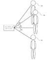
- FIG. 4 is a diagram for explaining sound collection by a microphone; It is a figure for demonstrating the arrival direction of a sound.
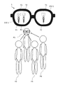
- FIG. 4 is a diagram showing a display example on a display device;
- FIG. 10 is a diagram for explaining how it looks in the field of vision of the wearer;
- FIG. 10 is a diagram showing how an image looks before display position adjustment; It is a figure which shows how it looks after display position adjustment. It is a figure which shows an example of the adjustment method of a display position.
- 9 is a flowchart showing an example of processing related to display position adjustment;
- FIG. 10 is a diagram for explaining a method of designating a display position adjustment target;
- FIG. 1 is a diagram showing a configuration example of a display device.
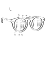
- FIG. 2 is a diagram showing the outline of a glass-type display device, which is an example of the display device shown in FIG.
- the display device 1 shown in FIG. 1 is configured to collect sound and display a text image corresponding to the collected sound in a manner corresponding to the direction of arrival of the sound.
- Forms of the display device 1 include, for example, at least one of the following. ⁇ Glass-type display devices ⁇ Head-mounted displays ⁇ Mobile terminals
- the display device 1 includes multiple microphones 101 , a display 102 , a sensor 104 , an operation section 105 and a controller 10 .
- Each microphone 101 is arranged so as to maintain a predetermined positional relationship with each other.
- the display device 1 when the display device 1 is a glass-type display device, the display device 1 includes a right temple 21, a right end piece 22, a bridge 23, a left end piece 24, a left temple 25, a rim 26 and is wearable by the user.
- a microphone 101 - 1 is arranged on the right temple 21 .
- a microphone 101 - 2 is placed on the right end piece 22 .
- a microphone 101 - 3 is placed on the bridge 23 .
- a microphone 101 - 4 is placed on the left end piece 24 .
- a microphone 101 - 5 is arranged on the left temple 25 .
- the microphone 101 picks up sounds around the display device 1, for example. Sounds collected by the microphone 101 include, for example, at least one of the following sounds. ⁇ Speech by a person ⁇ Sound of the environment where the display device 1 is used (hereinafter referred to as “environmental sound”)
- the display 102 is a transparent member (for example, at least one of glass, plastic, and half mirror). In this case, the display 102 is placed within the field of view of the user wearing the glass display device.
- the displays 102-1 to 102-2 are supported by the rim 26.
- the display 102-1 is arranged so as to be positioned in front of the user's right eye when the user wears the display device 1.
- FIG. The display 102-2 is arranged so as to be positioned in front of the user's left eye when the user wears the display device 1.
- the display 102 presents (for example, displays) an image under the control of the controller 10.
- a projector (not shown) placed behind the right temple 21 projects an image onto the display 102-1
- a projector (not shown) placed behind the left temple 25 projects an image onto the display 102-2. be done.
- the display 102-1 and the display 102-2 present images. The user can visually recognize the scenery transmitted through the display 102-1 and the display 102-2 at the same time as viewing the image.
- the method by which the display device 1 presents images is not limited to the above example.
- the display device 1 may project images directly from a projector to the user's eyes.
- a sensor 104 is a sensor that detects the state of the display device 1 .
- the sensor 104 includes a gyro sensor or a tilt sensor, and detects tilt of the display device 1 in the elevation direction.
- the type of the sensor 104 and the contents of the detected state are not limited to this example.
- the operation unit 105 accepts user operations.
- the operation unit 105 is, for example, a drive button, keyboard, pointing device, touch panel, remote controller, switch, or a combination thereof, and detects user operations on the display device 1 .
- the type of the operation unit 105 and the details of the detected operation are not limited to this example.
- the controller 10 is an information processing device that controls the display device 1 .
- the controller 10 is wired or wirelessly connected to the microphone 101, the display 102, the sensor 104, and the operation unit 105.
- FIG. When the display device 1 is a glass-type display device as shown in FIG. 2, the controller 10 is arranged inside the right temple 21, for example.
- the arrangement of the controller 10 is not limited to the example in FIG. 2, and the controller 10 may be configured separately from the display device 1, for example.
- the controller 10 includes a storage device 11, a processor 12, an input/output interface 13, and a communication interface 14.
- the storage device 11 is configured to store programs and data.
- the storage device 11 is, for example, a combination of ROM (Read Only Memory), RAM (Random Access Memory), and storage (eg, flash memory or hard disk).
- Programs include, for example, the following programs. ⁇ OS (Operating System) program ⁇ Application program that executes information processing
- the data includes, for example, the following data. ⁇ Databases referenced in information processing ⁇ Data obtained by executing information processing (that is, execution results of information processing)
- the processor 12 is configured to implement the functions of the controller 10 by activating programs stored in the storage device 11 .
- Processor 12 is an example of a computer.
- the processor 12 activates a program stored in the storage device 11 to display an image representing text (hereinafter referred to as a “text image”) corresponding to the speech sound collected by the microphone 101 at a predetermined position on the display 102 . Realize the function to be presented to.
- the display device 1 may have dedicated hardware such as ASIC or FPGA, and at least part of the processing of the processor 12 described in this embodiment may be executed by the dedicated hardware.
- the input/output interface 13 acquires at least one of the following. - Audio signal collected by the microphone 101 - Information indicating the state of the display device 1 detected by the sensor 104 - Input according to the user operation accepted by the operation unit 105 configured to output information to an output device connected to the An output device is, for example, the display 102 .
- the communication interface 14 is configured to control communication between the display device 1 and an external device (eg, server or mobile terminal) not shown.
- an external device eg, server or mobile terminal
- FIG. 3 is a diagram showing the functions of the display device.
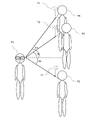
- a user P1 wearing a display device 1 is having a conversation with speakers P2 to P4.
- a microphone 101 picks up the uttered sounds of the speakers P2 to P4.
- the controller 10 estimates the direction of arrival of the collected speech sound.
- the controller 10 generates text images T1 to T3 corresponding to the speech sounds by analyzing audio signals corresponding to the collected speech sounds.
- the controller 10 determines the display position of each of the text images T1 to T3 according to the incoming direction of the speech sound and the adjustment amount determined based on the input from the sensor 104 or the operation unit 105.
- FIG. The details of the display position determination method will be described later with reference to FIGS. 9 to 13 and the like.
- the controller 10 displays the text images T1 to T3 at the determined display positions within the displays 102-1 to 102-2.
- FIG. 4 is a flowchart showing an example of processing of the controller 10 .
- FIG. 5 is a diagram for explaining sound collection by a microphone.
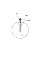
- FIG. 6 is a diagram for explaining the arrival direction of sound.
- a plurality of microphones 101 each collects the speech sound emitted by the speaker.
- microphones 101-1 to 101-5 are arranged on the right temple 21, right end piece 22, bridge 23, left end piece 24, and left temple 25 of the display device 1, respectively.
- Microphones 101-1 to 101-5 collect speech sounds arriving via the paths shown in FIG.
- Microphones 101-1 to 101-5 convert collected speech sounds into audio signals.
- the processing shown in FIG. 4 is started when the power of the display device 1 is turned on and the initial setting is completed.
- the start timing of the processing shown in FIG. 4 is not limited to this.
- the controller 10 acquires the audio signal converted by the microphone 101 (S110).
- the processor 12 acquires audio signals including speech sounds uttered by at least one of the speakers P2, P3, and P4, which are transmitted from the microphones 101-1 to 101-5.
- the audio signals transmitted from the microphones 101-1 to 101-5 contain spatial information based on paths along which speech sounds have traveled.
- step S110 the controller 10 performs direction-of-arrival estimation (S111).
- a direction-of-arrival estimation model is stored in the storage device 11 .
- the direction-of-arrival estimation model describes information for identifying the correlation between the spatial information included in the speech signal and the direction of arrival of the speech sound.
- the direction-of-arrival estimation method uses MUSIC (Multiple Signal Classification) using eigenvalue expansion of the input correlation matrix, minimum norm method, or ESPRIT (Estimation of Signal Parameters via Rotational Invariance Techniques).
- MUSIC Multiple Signal Classification
- ESPRIT Estimation of Signal Parameters via Rotational Invariance Techniques.
- the processor 12 inputs the sound signals received from the microphones 101-1 to 101-5 to the direction-of-arrival estimation model stored in the storage device 11, so that the sounds collected by the microphones 101-1 to 101-5 are input. Estimate direction of arrival of speech sound.
- the processor 12 sets the reference direction (in this embodiment, the front direction of the user wearing the display device 1) defined with reference to the microphones 101-1 to 101-5, from the axis with 0 degrees.
- the direction of arrival of the speech sound is expressed by the declination of .
- the processor 12 estimates the incoming direction of the speech sound emitted by the speaker P2 as an angle A1 to the right from the axis.
- the processor 12 estimates the incoming direction of the speech sound emitted by the speaker P3 to be an angle A2 to the left from the axis.
- the processor 12 estimates the incoming direction of the speech sound emitted by the speaker P4 to be an angle A3 to the left from the axis.
- step S111 the controller 10 executes audio signal extraction (S112).
- a beamforming model is stored in the storage device 11 .
- the beamforming model describes information for identifying a correlation between a predetermined direction and parameters for forming directivity having a beam in that direction.
- forming the directivity is a process of amplifying or attenuating a sound coming from a specific direction of arrival.
- the processor 12 inputs the estimated direction of arrival into the beamforming model stored in the storage device 11 to calculate parameters for forming directivity having a beam in the direction of arrival.
- the processor 12 inputs the calculated angle A1 into the beamforming model and calculates the parameters for forming the directivity with the beam in the direction of the angle A1 rightward from the axis.
- the processor 12 inputs the calculated angle A2 into the beamforming model and calculates the parameters for forming the directivity with the beam directed at the angle A2 to the left of the axis.
- the processor 12 inputs the calculated angle A3 into the beamforming model and calculates the parameters for forming the directivity with the beam directed at the angle A3 to the left of the axis.
- the processor 12 amplifies or attenuates the audio signals transmitted from the microphones 101-1 to 101-5 using the parameters calculated for the angle A1.
- the processor 12 extracts from the received audio signal the audio signal for the speech sound coming from the angle A1 by synthesizing the amplified or attenuated audio signal.
- the processor 12 amplifies or attenuates the audio signals transmitted from the microphones 101-1 to 101-5 using the parameters calculated for the angle A2.
- the processor 12 extracts from the received audio signal the audio signal for the speech sound coming from angle A2 by synthesizing the amplified or attenuated audio signal.
- the processor 12 amplifies or attenuates the audio signals transmitted from the microphones 101-1 to 101-5 using the parameters calculated for the angle A3.
- the processor 12 extracts from the received audio signal the audio signal for the speech sound coming from angle A3 by synthesizing the amplified or attenuated audio signal.
- step S112 the controller 10 executes voice recognition processing (S113).
- a speech recognition model is stored in the storage device 11.
- a speech recognition model describes information for identifying a speech signal and the correlation of text to the speech signal.
- a speech recognition model is, for example, a trained model generated by machine learning.
- the processor 12 determines text corresponding to the input speech signal.
- the processor 12 inputs the speech signals extracted for the angles A1 to A3 to the speech recognition model respectively, thereby determining the text corresponding to the input speech signals.
- step S113 the controller 10 executes image generation (S114).
- the processor 12 generates a text image representing the determined text.
- step S114 the controller 10 determines the display mode (S115).
- processor 12 determines how display images including text images are displayed on display 102 . After step S115, the controller 10 executes image display (S116).
- the processor 12 displays on the display 102 a display image according to the determined display mode.
- the processor 12 generates text on the display unit of the display device 1 based on the estimated direction of arrival of the sound and the adjustment amount determined based on the detection result of at least one of the operation by the user and the state of the display device 1 . Determines the display position of the image.
- FIG. 7 is a diagram showing a display example on a display device.
- FIG. 8 is a diagram for explaining how it looks in the field of view of the wearer.
- the images of the speakers P2 to P4 drawn with broken lines in FIG. 7 represent real images seen by the user P1 through the display 102.
- Text images T1 to T3 depicted in FIG. 9 represent images displayed on the display 102 and seen by the user P1, and do not exist in real space.
- the visual field seen through the display 102-1 and the visual field seen through the display 102-2 have different image positions depending on the parallax.
- the processor 12 determines the position corresponding to the incoming direction of the audio signal associated with the text image as the display position of the text image. More specifically, the processor 12 changes the display position of the text image T1 corresponding to the sound (speech sound of the speaker P2) coming from the direction of the angle A1 with respect to the display device 1 from the viewpoint of the user P1. Determine a position that can be seen in the direction corresponding to A1. The processor 12 shifts the display position of the text image T2 corresponding to the sound (speech sound of the speaker P3) coming from the direction of the angle A2 with respect to the display device 1 to the direction corresponding to the angle A2 when viewed from the viewpoint of the user P1. position where it can be seen.
- the processor 12 adjusts the display position of the text image T3 corresponding to the sound (speech sound of the speaker P4) coming from the direction of the angle A3 with respect to the display device 1 in the direction corresponding to the angle A3 when viewed from the viewpoint of the user P1. position where it can be seen.
- angles A1 to A3 represent azimuth angles.
- the text images T1 to T3 are displayed on the display 102 at display positions corresponding to the sound arrival direction.
- the text image T1 representing the utterance content of the speaker P2 is presented to the user P1 of the display device 1 together with the image of the speaker P2 seen through the display 102 .
- the text image T2 representing the contents of the speech of the speaker P3 is presented to the user P1 together with the image of the speaker P3 seen through the display 102 .
- the text image T3 representing the content of the speech of the speaker P4 is presented to the user P1 together with the image of the speaker P4 seen through the display 102 .
- the text image on the display 102 is also arranged so that the image of the speaker and the text image of the content of the statement can be seen in the same direction as viewed from the user P1.
- the display position of is changed. That is, the horizontal display position of the text image displayed on the display 102 is determined according to the estimated arrival direction and the orientation of the display device 1 .
- FIG. 9 is a diagram showing how it looks before display position adjustment.
- FIG. 10 is a diagram showing how it looks after the display position is adjusted.
- FIG. 11 is a diagram illustrating an example of a display position adjustment method.
- FIG. 9A shows a user P1, a field of view (FOV) 901 of the display device 1, a horizontal direction 903, and a display position of a text image 902 in which the utterance "Hello" by the speaker P2 is converted into text.
- a field of view (FOV) 901 is an angle range preset for the display device 1, and has a predetermined width in each of the elevation direction and the azimuth direction centered on the reference direction of the display device 1 (the front direction of the wearer).
- the FOV of the display device 1 is included in the field of view seen by the user through the display device 1 .
- FIG. 9(b) represents part of the field of view of the user P1 in the situation shown in FIG. 9(a).
- the display position adjustment amount is set to the initial value
- the position corresponding to the text image 902 in the horizontal direction when viewed from the viewpoint of the user P1 is The display position is determined so that the That is, the elevation angle of the direction in which the text image displayed on the display 102 can be seen from the viewpoint of the user P1 with respect to the horizontal direction is 0°.
- the text image 902 and the image of the speaker P2 overlap when viewed from the user P1.
- the text image 902 is positioned closer to the position in the horizontal direction when viewed from the viewpoint of the user P1.
- the display position is determined so that it can be seen below. That is, when viewed from the viewpoint of the user P1, the elevation angle with respect to the horizontal direction in which the text image displayed on the display 102 can be seen is -B1 (that is, the depression angle is +B1).
- the adjustment amount of the display position of the text image is determined based on the user's operation detected by the operation unit 105, for example. Specifically, when the operation unit 105 is a touch display installed in the display device 1 and the user P1 performs a touch operation on the operation unit 105, the controller 10 responds to the input from the operation unit 105. to determine the adjustment amount.
- the controller sets the elevation angle ⁇ B1 as the adjustment amount, even if the orientation of the display device 1 (that is, the orientation of the face of the user P1) changes, the text image can be viewed from the viewpoint of the user P1 with respect to the horizontal direction.
- the elevation angle is -B1. That is, the vertical display position of the text image displayed on the display 102 is determined according to the adjustment amount determined by the controller 10 and the orientation of the display device 1 .
- the adjustment amount of the display position of the text image is determined based on the state of the display device 1 detected by the sensor 104 .
- the sensor 104 is a sensor that detects the tilt of the display device 1
- the depression angle of the tilt of the display device 1 increases. Accordingly, the downward adjustment amount of the display position of the text image 902 on the display 102 increases.
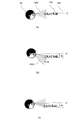
- FIG. 11(a) shows a situation in which the user P1 faces the front and the adjustment amount of the display position is the initial value.
- FIG. 11(b) shows a state in which the user P1 faces downward from the situation of FIG. 11(a) and the adjustment amount of the display position is changed.
- FIG. 11(c) shows a state in which the user P1 faces the front again from the situation of FIG. 11(b) and the adjustment amount of the display position is maintained at the value set in the situation of FIG. 11(b). show.
- the processor 12 updates the adjustment amount of the display position based on the following (equation 1) and (equation 2).
- ⁇ min( ⁇ u , ⁇ ) (Formula 1)
- ⁇ max( ⁇ l , ⁇ ) (Formula 2)
- ⁇ is an angle corresponding to the vertical adjustment amount of the display position of the text image
- ⁇ u is an angle indicating the direction of the upper end 1103 of the FOV 901
- ⁇ l is an angle indicating the direction of the lower end 1102 of the FOV 901. is.
- (Formula 1) indicates that the display position of the text image 902 is lowered so that the text image 902 does not move out of the FOV 901 when the user P1 looks down (when the depression angle of the display device 1 increases).
- (Formula 2) means that the display position of the text image 902 rises so as not to deviate from the FOV 901 when the user P1 looks up (when the elevation angle of the display device 1 increases).
- a case where the inclination of the display device 1 in the elevation direction is within a predetermined range is a case where the position of the text image 902 is not in contact with the upper end and the lower end of the FOV 901 . That is, the predetermined range is determined based on the elevation angle of the direction in which the text image 902 displayed on the display 102 can be seen from the viewpoint of the user P1 wearing the display device 1 with respect to the horizontal direction 903 .
- the user P1 can move the display position of the text image to a desired position simply by moving the face up or down. can be changed. As a result, the user P1 does not have to perform complicated operations to change the display position of the text image, and communication by the user P1 can be facilitated.
- the controller 10 determines the adjustment amount of the display position of the text image on the display unit of the display device 1 as a result of detection of at least one of the operation by the user and the state of the display device 1. to decide based on Then, the controller 10 displays the text image generated by the speech recognition at a position determined according to the estimated arrival direction of the speech and the determined adjustment amount.
- the wearer of the display device 1 can easily recognize in which direction the displayed text image represents the utterance of the person standing, and the face of the speaker is an important real object. Both text and images can be recognized at the same time. As a result, communication by users can be facilitated.
- the display device 1 is a display device that can be worn by the user. Then, the controller 10 determines the adjustment amount for the vertical display position of the text image on the display unit based on the tilt of the display device 1 in the elevation direction. This allows the user to adjust the display position of the text image with a simple gesture of moving the direction of the face.
- Modification 1 shows an example in which the adjustment amount of the display position of the text image is set for each target area.
- FIG. 12 is a flowchart illustrating an example of processing related to display position adjustment.
- FIG. 13 is a diagram for explaining a method of designating a display position adjustment target.
- the process of FIG. 12 is executed at the timing when an instruction corresponding to the user's operation or gesture for setting the adjustment amount of the display position is input to the display device 1 .
- the execution timing of the process of FIG. 12 is not limited to this.
- the processing of FIG. 12 can be executed in parallel with the processing shown in FIG.
- the controller 10 designates a target direction that serves as a reference for adjusting the text display position.
- the processor 12 designates the target direction based on the user's operation.
- the user P1 of the display device 1 wants to adjust the display position of the text image corresponding to the utterance of the speaker P2
- the user P1 performs an operation of specifying a target direction 1202, which is the direction in which the speaker P2 exists. conduct.
- the operation by the user may be, for example, a touch operation on the operation unit 105 performed while facing the target direction.
- the method of determining the target direction is not limited to this, and for example, a specific direction based on the orientation of the display device 1 may be determined in advance as the target direction.
- the controller 10 designates a target range to be adjusted for the text display position. Specifically, when the user P1 performs an operation of designating an angular width based on the target direction 1202, the processor 12 designates a target range 1203 based on the user's operation. If the user does not specify the angular width, the processor 12 designates the target range 1203 based on the angular width determined as a default value and the target direction 1202 . Alternatively, the processor 12 changes at least one of the position of the sound source, the number of sound sources, and the direction of arrival of the sound in the vicinity of the target direction 1202 so that the sound sources existing in the vicinity of the target direction 1202 are included in the target range 1203. You may specify the target range 1203 based on.
- the controller 10 identifies the target sound source whose text display position is to be adjusted. Specifically, processor 12 identifies a sound source existing within target range 1203 as a target sound source among the sound sources recognized based on the estimation result of the direction of arrival of the sound.
- the controller 10 sets the adjustment amount of the text display position.
- the method of setting the adjustment amount is the same as in the above-described embodiment.
- the controller 10 updates the display position of the text image based on the set adjustment amount.
- the processor 12 updates the display position of the text image corresponding to the sound source specified in S1303 based on the set adjustment amount. That is, the display position of the text image corresponding to the sound coming from the direction included in the target range 1203 specified in S1302 is updated based on the adjustment amount.
- the display position of the text image corresponding to the sound arriving from directions not included in the target range 1203 is not updated.
- the adjustment amount of the display position of the text image corresponding to the arrival direction is determined by the user operation and the display. It is determined based on the state of the device 1 and at least one detection result. This allows the user to adjust the display position of the text image corresponding to a specific sound source independently of the display positions of text images corresponding to other sound sources. For example, when there are a plurality of speakers with greatly different heights around the user, the user should correspond to the speaker's utterance at a height position corresponding to the height of the speaker on the display section of the display device 1. You can adjust the display position so that the text image is displayed. As a result, the user can easily communicate while viewing both the speaker's facial expression and the text image.
- the controller 10 can also set a different adjustment amount for each target range by performing the process of FIG. 12 multiple times and specifying multiple target ranges. In this case, the controller 10 can also set a different adjustment amount for each sound source by narrowly specifying each target range. The controller 10 can also uniformly set the adjustment amount of the display position of the text image for all incoming directions by specifying the angular width of the target range to be 360 degrees.
- an array microphone device having a plurality of microphones 101 may be configured separately from the display device 1 and connected to the display device 1 by wire or wirelessly.
- the array microphone device and display device 1 may be directly connected, or may be connected via another device such as a PC or a cloud server.
- the array microphone device and the display device 1 are configured separately, at least part of the functions of the display device 1 described above may be implemented in the array microphone device.
- the array microphone apparatus performs the estimation of the direction of arrival in S111 and the extraction of the audio signal in S112 of the processing flow of FIG. You may send.
- the display device 1 may then use the received information and audio signals to control the display of images, including text images.
- the display device 1 is an optical see-through glass-type display device.
- the format of the display device 1 is not limited to this.
- the display device 1 may be a video see-through glass type display device. That is, the display device 1 may comprise a camera. Then, the display device 1 may cause the display 102 to display a synthesized image obtained by synthesizing the text image generated based on the voice recognition and the captured image captured by the camera.
- the captured image is an image captured in front of the user and may include an image of the speaker.
- the controller 10 and the display 102 may be configured separately, such as the controller 10 existing in a cloud server.
- the horizontal display position of the text image on the display unit of the display device 1 is determined based on the estimation result of the direction of arrival of the sound, and the vertical display position of the text image is adjusted according to the adjustment amount described above.
- the explanation has focused on the case where the decision is made based on
- the adjustment amount described above may be used to determine the display position of the text image in the horizontal direction without being limited to this.
- the text image is displayed based on the adjustment amount set by the same method as in the above-described embodiment. may be adjusted in the horizontal direction. This makes it possible to reduce the deviation described above. Also, the display position of the text image in the horizontal direction may be intentionally shifted so that the image of the sound source and the text image do not overlap when viewed from the user. At this time, the controller 10 performs control so that the text image is displayed at a position shifted in the horizontal direction by a distance corresponding to the adjustment amount from the position calculated according to the sound arrival direction.
- the controller 10 may estimate the elevation angle of the sound arrival direction in the same way as estimating the azimuth angle of the sound arrival direction as in the above-described embodiment. The controller 10 may then determine the display position of the text image on the display device 1 based on the estimated elevation angle of the direction of arrival. Further, the controller 10 may perform control so that the text image is displayed at a position vertically shifted by a distance corresponding to the adjustment amount from the position calculated according to the direction of arrival of the sound.
- a user's instruction may be input from a drive button object presented by an application of a computer (for example, a smartphone) connected to the communication interface 14 .
- the display 102 can be implemented by any method as long as it can present an image to the user.
- the display 102 can be implemented by, for example, the following implementation method.
- ⁇ HOE Holographic optical element
- DOE diffractive optical element
- an optical element as an example, a light guide plate
- ⁇ Liquid crystal display ⁇ Retinal projection display
- LED Light Emitting Diode
- Organic EL Electro Luminescence
- ⁇ Laser display ⁇ Optical element (for example, lens, mirror, diffraction grating, liquid crystal, MEMS mirror, HOE) 2.
- any implementation method can be used as long as a voice signal corresponding to a specific speaker can be extracted.
- the controller 10 may, for example, extract the audio signal by the following method.
- Frost beamformer Adaptive filter beamforming generally sidelobe canceller as an example
- ⁇ Speech extraction methods other than beamforming for example, frequency filter or machine learning
- Reference Signs List 1 display device 10: controller 101: microphone 102: display 104: sensor 105: operation unit
Landscapes
- Engineering & Computer Science (AREA)
- Physics & Mathematics (AREA)
- Theoretical Computer Science (AREA)
- General Physics & Mathematics (AREA)
- Signal Processing (AREA)
- Acoustics & Sound (AREA)
- Computer Hardware Design (AREA)
- Human Computer Interaction (AREA)
- Health & Medical Sciences (AREA)
- Audiology, Speech & Language Pathology (AREA)
- Multimedia (AREA)
- General Engineering & Computer Science (AREA)
- Computational Linguistics (AREA)
- General Health & Medical Sciences (AREA)
- Business, Economics & Management (AREA)
- Educational Administration (AREA)
- Educational Technology (AREA)
- Optics & Photonics (AREA)
- User Interface Of Digital Computer (AREA)
Priority Applications (2)
| Application Number | Priority Date | Filing Date | Title |
|---|---|---|---|
| JP2023530454A JPWO2022270455A1 (https=) | 2021-06-21 | 2022-06-20 | |
| US18/545,081 US20240129686A1 (en) | 2021-06-21 | 2023-12-19 | Display control apparatus, and display control method |
Applications Claiming Priority (2)
| Application Number | Priority Date | Filing Date | Title |
|---|---|---|---|
| JP2021102245 | 2021-06-21 | ||
| JP2021-102245 | 2021-06-21 |
Related Child Applications (1)
| Application Number | Title | Priority Date | Filing Date |
|---|---|---|---|
| US18/545,081 Continuation US20240129686A1 (en) | 2021-06-21 | 2023-12-19 | Display control apparatus, and display control method |
Publications (1)
| Publication Number | Publication Date |
|---|---|
| WO2022270455A1 true WO2022270455A1 (ja) | 2022-12-29 |
Family
ID=84545664
Family Applications (1)
| Application Number | Title | Priority Date | Filing Date |
|---|---|---|---|
| PCT/JP2022/024486 Ceased WO2022270455A1 (ja) | 2021-06-21 | 2022-06-20 | 表示制御装置、表示制御方法、及びプログラム |
Country Status (3)
| Country | Link |
|---|---|
| US (1) | US20240129686A1 (https=) |
| JP (1) | JPWO2022270455A1 (https=) |
| WO (1) | WO2022270455A1 (https=) |
Citations (6)
| Publication number | Priority date | Publication date | Assignee | Title |
|---|---|---|---|---|
| JP2012059121A (ja) * | 2010-09-10 | 2012-03-22 | Softbank Mobile Corp | 眼鏡型表示装置 |
| WO2013145147A1 (ja) * | 2012-03-28 | 2013-10-03 | パイオニア株式会社 | ヘッドマウントディスプレイ及び表示方法 |
| JP2015072415A (ja) * | 2013-10-04 | 2015-04-16 | セイコーエプソン株式会社 | 表示装置、頭部装着型表示装置、表示装置の制御方法、および、頭部装着型表示装置の制御方法 |
| WO2016075782A1 (ja) * | 2014-11-12 | 2016-05-19 | 富士通株式会社 | ウェアラブルデバイス、表示制御方法、及び表示制御プログラム |
| US20170199543A1 (en) * | 2014-06-27 | 2017-07-13 | Lg Electronics Inc. | Glass-type terminal and method of controling the same |
| US20170277257A1 (en) * | 2016-03-23 | 2017-09-28 | Jeffrey Ota | Gaze-based sound selection |
Family Cites Families (7)
| Publication number | Priority date | Publication date | Assignee | Title |
|---|---|---|---|---|
| US9966075B2 (en) * | 2012-09-18 | 2018-05-08 | Qualcomm Incorporated | Leveraging head mounted displays to enable person-to-person interactions |
| CA3049379A1 (en) * | 2017-01-05 | 2018-07-12 | Philipp K. Lang | Improved accuracy of displayed virtual data with optical head mount displays for mixed reality |
| US11069368B2 (en) * | 2018-12-18 | 2021-07-20 | Colquitt Partners, Ltd. | Glasses with closed captioning, voice recognition, volume of speech detection, and translation capabilities |
| US11328692B2 (en) * | 2019-08-06 | 2022-05-10 | Alexandra Cartier | Head-mounted situational awareness system and method of operation |
| US20210174823A1 (en) * | 2019-12-10 | 2021-06-10 | Spectrum Accountable Care Company | System for and Method of Converting Spoken Words and Audio Cues into Spatially Accurate Caption Text for Augmented Reality Glasses |
| US12136433B2 (en) * | 2020-05-28 | 2024-11-05 | Snap Inc. | Eyewear including diarization |
| WO2022051097A1 (en) * | 2020-09-03 | 2022-03-10 | Spark23 Corp. | Eyeglass augmented reality speech to text device and method |
-
2022
- 2022-06-20 JP JP2023530454A patent/JPWO2022270455A1/ja active Pending
- 2022-06-20 WO PCT/JP2022/024486 patent/WO2022270455A1/ja not_active Ceased
-
2023
- 2023-12-19 US US18/545,081 patent/US20240129686A1/en active Pending
Patent Citations (6)
| Publication number | Priority date | Publication date | Assignee | Title |
|---|---|---|---|---|
| JP2012059121A (ja) * | 2010-09-10 | 2012-03-22 | Softbank Mobile Corp | 眼鏡型表示装置 |
| WO2013145147A1 (ja) * | 2012-03-28 | 2013-10-03 | パイオニア株式会社 | ヘッドマウントディスプレイ及び表示方法 |
| JP2015072415A (ja) * | 2013-10-04 | 2015-04-16 | セイコーエプソン株式会社 | 表示装置、頭部装着型表示装置、表示装置の制御方法、および、頭部装着型表示装置の制御方法 |
| US20170199543A1 (en) * | 2014-06-27 | 2017-07-13 | Lg Electronics Inc. | Glass-type terminal and method of controling the same |
| WO2016075782A1 (ja) * | 2014-11-12 | 2016-05-19 | 富士通株式会社 | ウェアラブルデバイス、表示制御方法、及び表示制御プログラム |
| US20170277257A1 (en) * | 2016-03-23 | 2017-09-28 | Jeffrey Ota | Gaze-based sound selection |
Also Published As
| Publication number | Publication date |
|---|---|
| JPWO2022270455A1 (https=) | 2022-12-29 |
| US20240129686A1 (en) | 2024-04-18 |
Similar Documents
| Publication | Publication Date | Title |
|---|---|---|
| JP6344125B2 (ja) | 表示装置、表示装置の制御方法、および、プログラム | |
| CN103869470B (zh) | 显示装置及其控制方法、头戴式显示装置及其控制方法 | |
| US9959591B2 (en) | Display apparatus, method for controlling display apparatus, and program | |
| TWI638188B (zh) | 顯示裝置、頭部配戴型顯示裝置、顯示系統及顯示裝置之控制方法 | |
| US20170277257A1 (en) | Gaze-based sound selection | |
| US20160133051A1 (en) | Display device, method of controlling the same, and program | |
| JP2016208348A (ja) | 表示装置、表示装置の制御方法、及び、プログラム | |
| JP6432197B2 (ja) | 表示装置、表示装置の制御方法、および、プログラム | |
| JP2016033757A (ja) | 表示装置、表示装置の制御方法、および、プログラム | |
| JP2017016056A (ja) | 表示システム、表示装置、表示装置の制御方法、及び、プログラム | |
| US12457448B2 (en) | Head-worn computing device with microphone beam steering | |
| JP2017102516A (ja) | 表示装置、通信システム、表示装置の制御方法、及び、プログラム | |
| JP6364735B2 (ja) | 表示装置、頭部装着型表示装置、表示装置の制御方法、および、頭部装着型表示装置の制御方法 | |
| JP2019023767A (ja) | 情報処理装置 | |
| JP2016033759A (ja) | 表示装置、表示装置の制御方法、および、プログラム | |
| US20240119684A1 (en) | Display control apparatus, display control method, and program | |
| JP6638195B2 (ja) | 表示装置、表示装置の制御方法、および、プログラム | |
| JP2026012872A (ja) | 情報処理装置、ディスプレイデバイス、提示方法、及びプログラム | |
| WO2022270455A1 (ja) | 表示制御装置、表示制御方法、及びプログラム | |
| JP2016033763A (ja) | 表示装置、表示装置の制御方法、および、プログラム | |
| US20240410969A1 (en) | Information processing apparatus and information processing method | |
| JP2023108945A (ja) | 情報処理装置、情報処理方法、及びプログラム | |
| WO2023249073A1 (ja) | 情報処理装置、ディスプレイデバイス、情報処理方法、及びプログラム | |
| EP4446869A1 (en) | Visualization and customization of sound space | |
| WO2021020069A1 (ja) | 表示装置、表示方法、及び、プログラム |
Legal Events
| Date | Code | Title | Description |
|---|---|---|---|
| 121 | Ep: the epo has been informed by wipo that ep was designated in this application |
Ref document number: 22828372 Country of ref document: EP Kind code of ref document: A1 |
|
| WWE | Wipo information: entry into national phase |
Ref document number: 2023530454 Country of ref document: JP |
|
| NENP | Non-entry into the national phase |
Ref country code: DE |
|
| 122 | Ep: pct application non-entry in european phase |
Ref document number: 22828372 Country of ref document: EP Kind code of ref document: A1 |