WO2022270455A1 - 表示制御装置、表示制御方法、及びプログラム - Google Patents
表示制御装置、表示制御方法、及びプログラム Download PDFInfo
- Publication number
- WO2022270455A1 WO2022270455A1 PCT/JP2022/024486 JP2022024486W WO2022270455A1 WO 2022270455 A1 WO2022270455 A1 WO 2022270455A1 JP 2022024486 W JP2022024486 W JP 2022024486W WO 2022270455 A1 WO2022270455 A1 WO 2022270455A1
- Authority
- WO
- WIPO (PCT)
- Prior art keywords
- display
- display device
- text image
- user
- adjustment amount
- Prior art date
Links
- 238000000034 method Methods 0.000 title claims description 28
- 238000001514 detection method Methods 0.000 claims abstract description 8
- 230000005236 sound signal Effects 0.000 description 24
- 238000010586 diagram Methods 0.000 description 17
- 238000004891 communication Methods 0.000 description 8
- 230000006870 function Effects 0.000 description 8
- 230000004048 modification Effects 0.000 description 8
- 238000012986 modification Methods 0.000 description 8
- 230000010365 information processing Effects 0.000 description 6
- 230000003287 optical effect Effects 0.000 description 5
- 239000000284 extract Substances 0.000 description 4
- 238000000605 extraction Methods 0.000 description 4
- 230000002194 synthesizing effect Effects 0.000 description 4
- 208000032041 Hearing impaired Diseases 0.000 description 3
- 230000002238 attenuated effect Effects 0.000 description 3
- 230000004438 eyesight Effects 0.000 description 3
- 230000008921 facial expression Effects 0.000 description 3
- 239000011521 glass Substances 0.000 description 3
- 238000005401 electroluminescence Methods 0.000 description 2
- 239000004973 liquid crystal related substance Substances 0.000 description 2
- 238000010801 machine learning Methods 0.000 description 2
- 230000004270 retinal projection Effects 0.000 description 2
- 230000000007 visual effect Effects 0.000 description 2
- 201000009487 Amblyopia Diseases 0.000 description 1
- 206010011878 Deafness Diseases 0.000 description 1
- 230000003213 activating effect Effects 0.000 description 1
- 230000003044 adaptive effect Effects 0.000 description 1
- 239000000470 constituent Substances 0.000 description 1
- 230000007423 decrease Effects 0.000 description 1
- 230000007613 environmental effect Effects 0.000 description 1
- 210000000887 face Anatomy 0.000 description 1
- 230000010370 hearing loss Effects 0.000 description 1
- 231100000888 hearing loss Toxicity 0.000 description 1
- 208000016354 hearing loss disease Diseases 0.000 description 1
- 239000011159 matrix material Substances 0.000 description 1
Images


Classifications
-
- H—ELECTRICITY
- H04—ELECTRIC COMMUNICATION TECHNIQUE
- H04S—STEREOPHONIC SYSTEMS
- H04S7/00—Indicating arrangements; Control arrangements, e.g. balance control
- H04S7/30—Control circuits for electronic adaptation of the sound field
- H04S7/302—Electronic adaptation of stereophonic sound system to listener position or orientation
- H04S7/303—Tracking of listener position or orientation
-
- G—PHYSICS
- G02—OPTICS
- G02B—OPTICAL ELEMENTS, SYSTEMS OR APPARATUS
- G02B27/00—Optical systems or apparatus not provided for by any of the groups G02B1/00 - G02B26/00, G02B30/00
- G02B27/02—Viewing or reading apparatus
-
- G—PHYSICS
- G06—COMPUTING; CALCULATING OR COUNTING
- G06F—ELECTRIC DIGITAL DATA PROCESSING
- G06F3/00—Input arrangements for transferring data to be processed into a form capable of being handled by the computer; Output arrangements for transferring data from processing unit to output unit, e.g. interface arrangements
- G06F3/01—Input arrangements or combined input and output arrangements for interaction between user and computer
-
- G—PHYSICS
- G09—EDUCATION; CRYPTOGRAPHY; DISPLAY; ADVERTISING; SEALS
- G09B—EDUCATIONAL OR DEMONSTRATION APPLIANCES; APPLIANCES FOR TEACHING, OR COMMUNICATING WITH, THE BLIND, DEAF OR MUTE; MODELS; PLANETARIA; GLOBES; MAPS; DIAGRAMS
- G09B21/00—Teaching, or communicating with, the blind, deaf or mute
-
- G—PHYSICS
- G09—EDUCATION; CRYPTOGRAPHY; DISPLAY; ADVERTISING; SEALS
- G09G—ARRANGEMENTS OR CIRCUITS FOR CONTROL OF INDICATING DEVICES USING STATIC MEANS TO PRESENT VARIABLE INFORMATION
- G09G5/00—Control arrangements or circuits for visual indicators common to cathode-ray tube indicators and other visual indicators
- G09G5/22—Control arrangements or circuits for visual indicators common to cathode-ray tube indicators and other visual indicators characterised by the display of characters or indicia using display control signals derived from coded signals representing the characters or indicia, e.g. with a character-code memory
- G09G5/32—Control arrangements or circuits for visual indicators common to cathode-ray tube indicators and other visual indicators characterised by the display of characters or indicia using display control signals derived from coded signals representing the characters or indicia, e.g. with a character-code memory with means for controlling the display position
-
- G—PHYSICS
- G09—EDUCATION; CRYPTOGRAPHY; DISPLAY; ADVERTISING; SEALS
- G09G—ARRANGEMENTS OR CIRCUITS FOR CONTROL OF INDICATING DEVICES USING STATIC MEANS TO PRESENT VARIABLE INFORMATION
- G09G5/00—Control arrangements or circuits for visual indicators common to cathode-ray tube indicators and other visual indicators
- G09G5/36—Control arrangements or circuits for visual indicators common to cathode-ray tube indicators and other visual indicators characterised by the display of a graphic pattern, e.g. using an all-points-addressable [APA] memory
- G09G5/38—Control arrangements or circuits for visual indicators common to cathode-ray tube indicators and other visual indicators characterised by the display of a graphic pattern, e.g. using an all-points-addressable [APA] memory with means for controlling the display position
-
- G—PHYSICS
- G10—MUSICAL INSTRUMENTS; ACOUSTICS
- G10L—SPEECH ANALYSIS TECHNIQUES OR SPEECH SYNTHESIS; SPEECH RECOGNITION; SPEECH OR VOICE PROCESSING TECHNIQUES; SPEECH OR AUDIO CODING OR DECODING
- G10L15/00—Speech recognition
- G10L15/28—Constructional details of speech recognition systems
-
- G—PHYSICS
- G10—MUSICAL INSTRUMENTS; ACOUSTICS
- G10L—SPEECH ANALYSIS TECHNIQUES OR SPEECH SYNTHESIS; SPEECH RECOGNITION; SPEECH OR VOICE PROCESSING TECHNIQUES; SPEECH OR AUDIO CODING OR DECODING
- G10L25/00—Speech or voice analysis techniques not restricted to a single one of groups G10L15/00 - G10L21/00
- G10L25/48—Speech or voice analysis techniques not restricted to a single one of groups G10L15/00 - G10L21/00 specially adapted for particular use
- G10L25/51—Speech or voice analysis techniques not restricted to a single one of groups G10L15/00 - G10L21/00 specially adapted for particular use for comparison or discrimination
-
- H—ELECTRICITY
- H04—ELECTRIC COMMUNICATION TECHNIQUE
- H04N—PICTORIAL COMMUNICATION, e.g. TELEVISION
- H04N5/00—Details of television systems
- H04N5/64—Constructional details of receivers, e.g. cabinets or dust covers
-
- H—ELECTRICITY
- H04—ELECTRIC COMMUNICATION TECHNIQUE
- H04R—LOUDSPEAKERS, MICROPHONES, GRAMOPHONE PICK-UPS OR LIKE ACOUSTIC ELECTROMECHANICAL TRANSDUCERS; DEAF-AID SETS; PUBLIC ADDRESS SYSTEMS
- H04R3/00—Circuits for transducers, loudspeakers or microphones
- H04R3/005—Circuits for transducers, loudspeakers or microphones for combining the signals of two or more microphones
-
- H—ELECTRICITY
- H04—ELECTRIC COMMUNICATION TECHNIQUE
- H04S—STEREOPHONIC SYSTEMS
- H04S2400/00—Details of stereophonic systems covered by H04S but not provided for in its groups
- H04S2400/11—Positioning of individual sound objects, e.g. moving airplane, within a sound field
Definitions
- the present disclosure relates to a display control device, a display control method, and a program.
- Patent Literature 1 discloses a head-mounted display device for assisting hearing-impaired persons in recognizing ambient sounds. This device allows the wearer to visually recognize the surrounding sounds by displaying the results of speech recognition of ambient sounds using multiple microphones as text information in a part of the wearer's field of vision. make it possible.
- An object of the present disclosure is to provide a user-friendly display method in a display device that displays a text image corresponding to voice within the user's field of view.
- a display control device has, for example, the following configuration. That is, a display control device for controlling the display of a display device wearable by a user, comprising acquisition means for acquiring sounds collected by a plurality of microphones, and estimating the direction of arrival of the sounds acquired by the acquisition means. generation means for generating a text image corresponding to the voice acquired by the acquisition means; and adjustment amount of the display position of the text image on the display section of the display device, the user's operation and the display device.
- determining means for determining based on at least one detection result of a state, and determining the text image generated by the generating means as a display position within the display unit and the direction of arrival estimated by the estimating means and the determining means and display control means for displaying at a display position determined according to the adjustment amount determined by the means.
- FIG. 1 is a schematic diagram of a display device;
- FIG. Fig. 3 shows the function of the display device;
- 4 is a flowchart showing an example of processing by a controller;
- FIG. 4 is a diagram for explaining sound collection by a microphone; It is a figure for demonstrating the arrival direction of a sound.
- FIG. 4 is a diagram showing a display example on a display device;
- FIG. 10 is a diagram for explaining how it looks in the field of vision of the wearer;
- FIG. 10 is a diagram showing how an image looks before display position adjustment; It is a figure which shows how it looks after display position adjustment. It is a figure which shows an example of the adjustment method of a display position.
- 9 is a flowchart showing an example of processing related to display position adjustment;
- FIG. 10 is a diagram for explaining a method of designating a display position adjustment target;
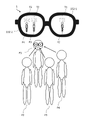
- FIG. 1 is a diagram showing a configuration example of a display device.
- FIG. 2 is a diagram showing the outline of a glass-type display device, which is an example of the display device shown in FIG.
- the display device 1 shown in FIG. 1 is configured to collect sound and display a text image corresponding to the collected sound in a manner corresponding to the direction of arrival of the sound.
- Forms of the display device 1 include, for example, at least one of the following. ⁇ Glass-type display devices ⁇ Head-mounted displays ⁇ Mobile terminals
- the display device 1 includes multiple microphones 101 , a display 102 , a sensor 104 , an operation section 105 and a controller 10 .
- Each microphone 101 is arranged so as to maintain a predetermined positional relationship with each other.
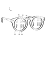
- the display device 1 when the display device 1 is a glass-type display device, the display device 1 includes a right temple 21, a right end piece 22, a bridge 23, a left end piece 24, a left temple 25, a rim 26 and is wearable by the user.
- a microphone 101 - 1 is arranged on the right temple 21 .
- a microphone 101 - 2 is placed on the right end piece 22 .
- a microphone 101 - 3 is placed on the bridge 23 .
- a microphone 101 - 4 is placed on the left end piece 24 .
- a microphone 101 - 5 is arranged on the left temple 25 .
- the microphone 101 picks up sounds around the display device 1, for example. Sounds collected by the microphone 101 include, for example, at least one of the following sounds. ⁇ Speech by a person ⁇ Sound of the environment where the display device 1 is used (hereinafter referred to as “environmental sound”)
- the display 102 is a transparent member (for example, at least one of glass, plastic, and half mirror). In this case, the display 102 is placed within the field of view of the user wearing the glass display device.
- the displays 102-1 to 102-2 are supported by the rim 26.
- the display 102-1 is arranged so as to be positioned in front of the user's right eye when the user wears the display device 1.
- FIG. The display 102-2 is arranged so as to be positioned in front of the user's left eye when the user wears the display device 1.
- the display 102 presents (for example, displays) an image under the control of the controller 10.
- a projector (not shown) placed behind the right temple 21 projects an image onto the display 102-1
- a projector (not shown) placed behind the left temple 25 projects an image onto the display 102-2. be done.
- the display 102-1 and the display 102-2 present images. The user can visually recognize the scenery transmitted through the display 102-1 and the display 102-2 at the same time as viewing the image.
- the method by which the display device 1 presents images is not limited to the above example.
- the display device 1 may project images directly from a projector to the user's eyes.
- a sensor 104 is a sensor that detects the state of the display device 1 .
- the sensor 104 includes a gyro sensor or a tilt sensor, and detects tilt of the display device 1 in the elevation direction.
- the type of the sensor 104 and the contents of the detected state are not limited to this example.
- the operation unit 105 accepts user operations.
- the operation unit 105 is, for example, a drive button, keyboard, pointing device, touch panel, remote controller, switch, or a combination thereof, and detects user operations on the display device 1 .
- the type of the operation unit 105 and the details of the detected operation are not limited to this example.
- the controller 10 is an information processing device that controls the display device 1 .
- the controller 10 is wired or wirelessly connected to the microphone 101, the display 102, the sensor 104, and the operation unit 105.
- FIG. When the display device 1 is a glass-type display device as shown in FIG. 2, the controller 10 is arranged inside the right temple 21, for example.
- the arrangement of the controller 10 is not limited to the example in FIG. 2, and the controller 10 may be configured separately from the display device 1, for example.
- the controller 10 includes a storage device 11, a processor 12, an input/output interface 13, and a communication interface 14.
- the storage device 11 is configured to store programs and data.
- the storage device 11 is, for example, a combination of ROM (Read Only Memory), RAM (Random Access Memory), and storage (eg, flash memory or hard disk).
- Programs include, for example, the following programs. ⁇ OS (Operating System) program ⁇ Application program that executes information processing
- the data includes, for example, the following data. ⁇ Databases referenced in information processing ⁇ Data obtained by executing information processing (that is, execution results of information processing)
- the processor 12 is configured to implement the functions of the controller 10 by activating programs stored in the storage device 11 .
- Processor 12 is an example of a computer.
- the processor 12 activates a program stored in the storage device 11 to display an image representing text (hereinafter referred to as a “text image”) corresponding to the speech sound collected by the microphone 101 at a predetermined position on the display 102 . Realize the function to be presented to.
- the display device 1 may have dedicated hardware such as ASIC or FPGA, and at least part of the processing of the processor 12 described in this embodiment may be executed by the dedicated hardware.
- the input/output interface 13 acquires at least one of the following. - Audio signal collected by the microphone 101 - Information indicating the state of the display device 1 detected by the sensor 104 - Input according to the user operation accepted by the operation unit 105 configured to output information to an output device connected to the An output device is, for example, the display 102 .
- the communication interface 14 is configured to control communication between the display device 1 and an external device (eg, server or mobile terminal) not shown.
- an external device eg, server or mobile terminal
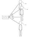
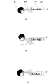
- FIG. 3 is a diagram showing the functions of the display device.
- a user P1 wearing a display device 1 is having a conversation with speakers P2 to P4.
- a microphone 101 picks up the uttered sounds of the speakers P2 to P4.
- the controller 10 estimates the direction of arrival of the collected speech sound.
- the controller 10 generates text images T1 to T3 corresponding to the speech sounds by analyzing audio signals corresponding to the collected speech sounds.
- the controller 10 determines the display position of each of the text images T1 to T3 according to the incoming direction of the speech sound and the adjustment amount determined based on the input from the sensor 104 or the operation unit 105.
- FIG. The details of the display position determination method will be described later with reference to FIGS. 9 to 13 and the like.
- the controller 10 displays the text images T1 to T3 at the determined display positions within the displays 102-1 to 102-2.
- FIG. 4 is a flowchart showing an example of processing of the controller 10 .
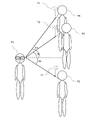
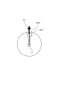
- FIG. 5 is a diagram for explaining sound collection by a microphone.
- FIG. 6 is a diagram for explaining the arrival direction of sound.
- a plurality of microphones 101 each collects the speech sound emitted by the speaker.
- microphones 101-1 to 101-5 are arranged on the right temple 21, right end piece 22, bridge 23, left end piece 24, and left temple 25 of the display device 1, respectively.
- Microphones 101-1 to 101-5 collect speech sounds arriving via the paths shown in FIG.
- Microphones 101-1 to 101-5 convert collected speech sounds into audio signals.
- the processing shown in FIG. 4 is started when the power of the display device 1 is turned on and the initial setting is completed.
- the start timing of the processing shown in FIG. 4 is not limited to this.
- the controller 10 acquires the audio signal converted by the microphone 101 (S110).
- the processor 12 acquires audio signals including speech sounds uttered by at least one of the speakers P2, P3, and P4, which are transmitted from the microphones 101-1 to 101-5.
- the audio signals transmitted from the microphones 101-1 to 101-5 contain spatial information based on paths along which speech sounds have traveled.
- step S110 the controller 10 performs direction-of-arrival estimation (S111).
- a direction-of-arrival estimation model is stored in the storage device 11 .
- the direction-of-arrival estimation model describes information for identifying the correlation between the spatial information included in the speech signal and the direction of arrival of the speech sound.
- the direction-of-arrival estimation method uses MUSIC (Multiple Signal Classification) using eigenvalue expansion of the input correlation matrix, minimum norm method, or ESPRIT (Estimation of Signal Parameters via Rotational Invariance Techniques).
- MUSIC Multiple Signal Classification
- ESPRIT Estimation of Signal Parameters via Rotational Invariance Techniques.
- the processor 12 inputs the sound signals received from the microphones 101-1 to 101-5 to the direction-of-arrival estimation model stored in the storage device 11, so that the sounds collected by the microphones 101-1 to 101-5 are input. Estimate direction of arrival of speech sound.
- the processor 12 sets the reference direction (in this embodiment, the front direction of the user wearing the display device 1) defined with reference to the microphones 101-1 to 101-5, from the axis with 0 degrees.
- the direction of arrival of the speech sound is expressed by the declination of .
- the processor 12 estimates the incoming direction of the speech sound emitted by the speaker P2 as an angle A1 to the right from the axis.
- the processor 12 estimates the incoming direction of the speech sound emitted by the speaker P3 to be an angle A2 to the left from the axis.
- the processor 12 estimates the incoming direction of the speech sound emitted by the speaker P4 to be an angle A3 to the left from the axis.
- step S111 the controller 10 executes audio signal extraction (S112).
- a beamforming model is stored in the storage device 11 .
- the beamforming model describes information for identifying a correlation between a predetermined direction and parameters for forming directivity having a beam in that direction.
- forming the directivity is a process of amplifying or attenuating a sound coming from a specific direction of arrival.
- the processor 12 inputs the estimated direction of arrival into the beamforming model stored in the storage device 11 to calculate parameters for forming directivity having a beam in the direction of arrival.
- the processor 12 inputs the calculated angle A1 into the beamforming model and calculates the parameters for forming the directivity with the beam in the direction of the angle A1 rightward from the axis.
- the processor 12 inputs the calculated angle A2 into the beamforming model and calculates the parameters for forming the directivity with the beam directed at the angle A2 to the left of the axis.
- the processor 12 inputs the calculated angle A3 into the beamforming model and calculates the parameters for forming the directivity with the beam directed at the angle A3 to the left of the axis.
- the processor 12 amplifies or attenuates the audio signals transmitted from the microphones 101-1 to 101-5 using the parameters calculated for the angle A1.
- the processor 12 extracts from the received audio signal the audio signal for the speech sound coming from the angle A1 by synthesizing the amplified or attenuated audio signal.
- the processor 12 amplifies or attenuates the audio signals transmitted from the microphones 101-1 to 101-5 using the parameters calculated for the angle A2.
- the processor 12 extracts from the received audio signal the audio signal for the speech sound coming from angle A2 by synthesizing the amplified or attenuated audio signal.
- the processor 12 amplifies or attenuates the audio signals transmitted from the microphones 101-1 to 101-5 using the parameters calculated for the angle A3.
- the processor 12 extracts from the received audio signal the audio signal for the speech sound coming from angle A3 by synthesizing the amplified or attenuated audio signal.
- step S112 the controller 10 executes voice recognition processing (S113).
- a speech recognition model is stored in the storage device 11.
- a speech recognition model describes information for identifying a speech signal and the correlation of text to the speech signal.
- a speech recognition model is, for example, a trained model generated by machine learning.
- the processor 12 determines text corresponding to the input speech signal.
- the processor 12 inputs the speech signals extracted for the angles A1 to A3 to the speech recognition model respectively, thereby determining the text corresponding to the input speech signals.
- step S113 the controller 10 executes image generation (S114).
- the processor 12 generates a text image representing the determined text.
- step S114 the controller 10 determines the display mode (S115).
- processor 12 determines how display images including text images are displayed on display 102 . After step S115, the controller 10 executes image display (S116).
- the processor 12 displays on the display 102 a display image according to the determined display mode.
- the processor 12 generates text on the display unit of the display device 1 based on the estimated direction of arrival of the sound and the adjustment amount determined based on the detection result of at least one of the operation by the user and the state of the display device 1 . Determines the display position of the image.
- FIG. 7 is a diagram showing a display example on a display device.
- FIG. 8 is a diagram for explaining how it looks in the field of view of the wearer.
- the images of the speakers P2 to P4 drawn with broken lines in FIG. 7 represent real images seen by the user P1 through the display 102.
- Text images T1 to T3 depicted in FIG. 9 represent images displayed on the display 102 and seen by the user P1, and do not exist in real space.
- the visual field seen through the display 102-1 and the visual field seen through the display 102-2 have different image positions depending on the parallax.
- the processor 12 determines the position corresponding to the incoming direction of the audio signal associated with the text image as the display position of the text image. More specifically, the processor 12 changes the display position of the text image T1 corresponding to the sound (speech sound of the speaker P2) coming from the direction of the angle A1 with respect to the display device 1 from the viewpoint of the user P1. Determine a position that can be seen in the direction corresponding to A1. The processor 12 shifts the display position of the text image T2 corresponding to the sound (speech sound of the speaker P3) coming from the direction of the angle A2 with respect to the display device 1 to the direction corresponding to the angle A2 when viewed from the viewpoint of the user P1. position where it can be seen.
- the processor 12 adjusts the display position of the text image T3 corresponding to the sound (speech sound of the speaker P4) coming from the direction of the angle A3 with respect to the display device 1 in the direction corresponding to the angle A3 when viewed from the viewpoint of the user P1. position where it can be seen.
- angles A1 to A3 represent azimuth angles.
- the text images T1 to T3 are displayed on the display 102 at display positions corresponding to the sound arrival direction.
- the text image T1 representing the utterance content of the speaker P2 is presented to the user P1 of the display device 1 together with the image of the speaker P2 seen through the display 102 .
- the text image T2 representing the contents of the speech of the speaker P3 is presented to the user P1 together with the image of the speaker P3 seen through the display 102 .
- the text image T3 representing the content of the speech of the speaker P4 is presented to the user P1 together with the image of the speaker P4 seen through the display 102 .
- the text image on the display 102 is also arranged so that the image of the speaker and the text image of the content of the statement can be seen in the same direction as viewed from the user P1.
- the display position of is changed. That is, the horizontal display position of the text image displayed on the display 102 is determined according to the estimated arrival direction and the orientation of the display device 1 .
- FIG. 9 is a diagram showing how it looks before display position adjustment.
- FIG. 10 is a diagram showing how it looks after the display position is adjusted.
- FIG. 11 is a diagram illustrating an example of a display position adjustment method.
- FIG. 9A shows a user P1, a field of view (FOV) 901 of the display device 1, a horizontal direction 903, and a display position of a text image 902 in which the utterance "Hello" by the speaker P2 is converted into text.
- a field of view (FOV) 901 is an angle range preset for the display device 1, and has a predetermined width in each of the elevation direction and the azimuth direction centered on the reference direction of the display device 1 (the front direction of the wearer).
- the FOV of the display device 1 is included in the field of view seen by the user through the display device 1 .
- FIG. 9(b) represents part of the field of view of the user P1 in the situation shown in FIG. 9(a).
- the display position adjustment amount is set to the initial value
- the position corresponding to the text image 902 in the horizontal direction when viewed from the viewpoint of the user P1 is The display position is determined so that the That is, the elevation angle of the direction in which the text image displayed on the display 102 can be seen from the viewpoint of the user P1 with respect to the horizontal direction is 0°.
- the text image 902 and the image of the speaker P2 overlap when viewed from the user P1.
- the text image 902 is positioned closer to the position in the horizontal direction when viewed from the viewpoint of the user P1.
- the display position is determined so that it can be seen below. That is, when viewed from the viewpoint of the user P1, the elevation angle with respect to the horizontal direction in which the text image displayed on the display 102 can be seen is -B1 (that is, the depression angle is +B1).
- the adjustment amount of the display position of the text image is determined based on the user's operation detected by the operation unit 105, for example. Specifically, when the operation unit 105 is a touch display installed in the display device 1 and the user P1 performs a touch operation on the operation unit 105, the controller 10 responds to the input from the operation unit 105. to determine the adjustment amount.
- the controller sets the elevation angle ⁇ B1 as the adjustment amount, even if the orientation of the display device 1 (that is, the orientation of the face of the user P1) changes, the text image can be viewed from the viewpoint of the user P1 with respect to the horizontal direction.
- the elevation angle is -B1. That is, the vertical display position of the text image displayed on the display 102 is determined according to the adjustment amount determined by the controller 10 and the orientation of the display device 1 .
- the adjustment amount of the display position of the text image is determined based on the state of the display device 1 detected by the sensor 104 .
- the sensor 104 is a sensor that detects the tilt of the display device 1
- the depression angle of the tilt of the display device 1 increases. Accordingly, the downward adjustment amount of the display position of the text image 902 on the display 102 increases.
- FIG. 11(a) shows a situation in which the user P1 faces the front and the adjustment amount of the display position is the initial value.
- FIG. 11(b) shows a state in which the user P1 faces downward from the situation of FIG. 11(a) and the adjustment amount of the display position is changed.
- FIG. 11(c) shows a state in which the user P1 faces the front again from the situation of FIG. 11(b) and the adjustment amount of the display position is maintained at the value set in the situation of FIG. 11(b). show.
- the processor 12 updates the adjustment amount of the display position based on the following (equation 1) and (equation 2).
- ⁇ min( ⁇ u , ⁇ ) (Formula 1)
- ⁇ max( ⁇ l , ⁇ ) (Formula 2)
- ⁇ is an angle corresponding to the vertical adjustment amount of the display position of the text image
- ⁇ u is an angle indicating the direction of the upper end 1103 of the FOV 901
- ⁇ l is an angle indicating the direction of the lower end 1102 of the FOV 901. is.
- (Formula 1) indicates that the display position of the text image 902 is lowered so that the text image 902 does not move out of the FOV 901 when the user P1 looks down (when the depression angle of the display device 1 increases).
- (Formula 2) means that the display position of the text image 902 rises so as not to deviate from the FOV 901 when the user P1 looks up (when the elevation angle of the display device 1 increases).
- a case where the inclination of the display device 1 in the elevation direction is within a predetermined range is a case where the position of the text image 902 is not in contact with the upper end and the lower end of the FOV 901 . That is, the predetermined range is determined based on the elevation angle of the direction in which the text image 902 displayed on the display 102 can be seen from the viewpoint of the user P1 wearing the display device 1 with respect to the horizontal direction 903 .
- the user P1 can move the display position of the text image to a desired position simply by moving the face up or down. can be changed. As a result, the user P1 does not have to perform complicated operations to change the display position of the text image, and communication by the user P1 can be facilitated.
- the controller 10 determines the adjustment amount of the display position of the text image on the display unit of the display device 1 as a result of detection of at least one of the operation by the user and the state of the display device 1. to decide based on Then, the controller 10 displays the text image generated by the speech recognition at a position determined according to the estimated arrival direction of the speech and the determined adjustment amount.
- the wearer of the display device 1 can easily recognize in which direction the displayed text image represents the utterance of the person standing, and the face of the speaker is an important real object. Both text and images can be recognized at the same time. As a result, communication by users can be facilitated.
- the display device 1 is a display device that can be worn by the user. Then, the controller 10 determines the adjustment amount for the vertical display position of the text image on the display unit based on the tilt of the display device 1 in the elevation direction. This allows the user to adjust the display position of the text image with a simple gesture of moving the direction of the face.
- Modification 1 shows an example in which the adjustment amount of the display position of the text image is set for each target area.
- FIG. 12 is a flowchart illustrating an example of processing related to display position adjustment.
- FIG. 13 is a diagram for explaining a method of designating a display position adjustment target.
- the process of FIG. 12 is executed at the timing when an instruction corresponding to the user's operation or gesture for setting the adjustment amount of the display position is input to the display device 1 .
- the execution timing of the process of FIG. 12 is not limited to this.
- the processing of FIG. 12 can be executed in parallel with the processing shown in FIG.
- the controller 10 designates a target direction that serves as a reference for adjusting the text display position.
- the processor 12 designates the target direction based on the user's operation.
- the user P1 of the display device 1 wants to adjust the display position of the text image corresponding to the utterance of the speaker P2
- the user P1 performs an operation of specifying a target direction 1202, which is the direction in which the speaker P2 exists. conduct.
- the operation by the user may be, for example, a touch operation on the operation unit 105 performed while facing the target direction.
- the method of determining the target direction is not limited to this, and for example, a specific direction based on the orientation of the display device 1 may be determined in advance as the target direction.
- the controller 10 designates a target range to be adjusted for the text display position. Specifically, when the user P1 performs an operation of designating an angular width based on the target direction 1202, the processor 12 designates a target range 1203 based on the user's operation. If the user does not specify the angular width, the processor 12 designates the target range 1203 based on the angular width determined as a default value and the target direction 1202 . Alternatively, the processor 12 changes at least one of the position of the sound source, the number of sound sources, and the direction of arrival of the sound in the vicinity of the target direction 1202 so that the sound sources existing in the vicinity of the target direction 1202 are included in the target range 1203. You may specify the target range 1203 based on.
- the controller 10 identifies the target sound source whose text display position is to be adjusted. Specifically, processor 12 identifies a sound source existing within target range 1203 as a target sound source among the sound sources recognized based on the estimation result of the direction of arrival of the sound.
- the controller 10 sets the adjustment amount of the text display position.
- the method of setting the adjustment amount is the same as in the above-described embodiment.
- the controller 10 updates the display position of the text image based on the set adjustment amount.
- the processor 12 updates the display position of the text image corresponding to the sound source specified in S1303 based on the set adjustment amount. That is, the display position of the text image corresponding to the sound coming from the direction included in the target range 1203 specified in S1302 is updated based on the adjustment amount.
- the display position of the text image corresponding to the sound arriving from directions not included in the target range 1203 is not updated.
- the adjustment amount of the display position of the text image corresponding to the arrival direction is determined by the user operation and the display. It is determined based on the state of the device 1 and at least one detection result. This allows the user to adjust the display position of the text image corresponding to a specific sound source independently of the display positions of text images corresponding to other sound sources. For example, when there are a plurality of speakers with greatly different heights around the user, the user should correspond to the speaker's utterance at a height position corresponding to the height of the speaker on the display section of the display device 1. You can adjust the display position so that the text image is displayed. As a result, the user can easily communicate while viewing both the speaker's facial expression and the text image.
- the controller 10 can also set a different adjustment amount for each target range by performing the process of FIG. 12 multiple times and specifying multiple target ranges. In this case, the controller 10 can also set a different adjustment amount for each sound source by narrowly specifying each target range. The controller 10 can also uniformly set the adjustment amount of the display position of the text image for all incoming directions by specifying the angular width of the target range to be 360 degrees.
- an array microphone device having a plurality of microphones 101 may be configured separately from the display device 1 and connected to the display device 1 by wire or wirelessly.
- the array microphone device and display device 1 may be directly connected, or may be connected via another device such as a PC or a cloud server.
- the array microphone device and the display device 1 are configured separately, at least part of the functions of the display device 1 described above may be implemented in the array microphone device.
- the array microphone apparatus performs the estimation of the direction of arrival in S111 and the extraction of the audio signal in S112 of the processing flow of FIG. You may send.
- the display device 1 may then use the received information and audio signals to control the display of images, including text images.
- the display device 1 is an optical see-through glass-type display device.
- the format of the display device 1 is not limited to this.
- the display device 1 may be a video see-through glass type display device. That is, the display device 1 may comprise a camera. Then, the display device 1 may cause the display 102 to display a synthesized image obtained by synthesizing the text image generated based on the voice recognition and the captured image captured by the camera.
- the captured image is an image captured in front of the user and may include an image of the speaker.
- the controller 10 and the display 102 may be configured separately, such as the controller 10 existing in a cloud server.
- the horizontal display position of the text image on the display unit of the display device 1 is determined based on the estimation result of the direction of arrival of the sound, and the vertical display position of the text image is adjusted according to the adjustment amount described above.
- the explanation has focused on the case where the decision is made based on
- the adjustment amount described above may be used to determine the display position of the text image in the horizontal direction without being limited to this.
- the text image is displayed based on the adjustment amount set by the same method as in the above-described embodiment. may be adjusted in the horizontal direction. This makes it possible to reduce the deviation described above. Also, the display position of the text image in the horizontal direction may be intentionally shifted so that the image of the sound source and the text image do not overlap when viewed from the user. At this time, the controller 10 performs control so that the text image is displayed at a position shifted in the horizontal direction by a distance corresponding to the adjustment amount from the position calculated according to the sound arrival direction.
- the controller 10 may estimate the elevation angle of the sound arrival direction in the same way as estimating the azimuth angle of the sound arrival direction as in the above-described embodiment. The controller 10 may then determine the display position of the text image on the display device 1 based on the estimated elevation angle of the direction of arrival. Further, the controller 10 may perform control so that the text image is displayed at a position vertically shifted by a distance corresponding to the adjustment amount from the position calculated according to the direction of arrival of the sound.
- a user's instruction may be input from a drive button object presented by an application of a computer (for example, a smartphone) connected to the communication interface 14 .
- the display 102 can be implemented by any method as long as it can present an image to the user.
- the display 102 can be implemented by, for example, the following implementation method.
- ⁇ HOE Holographic optical element
- DOE diffractive optical element
- an optical element as an example, a light guide plate
- ⁇ Liquid crystal display ⁇ Retinal projection display
- LED Light Emitting Diode
- Organic EL Electro Luminescence
- ⁇ Laser display ⁇ Optical element (for example, lens, mirror, diffraction grating, liquid crystal, MEMS mirror, HOE) 2.
- any implementation method can be used as long as a voice signal corresponding to a specific speaker can be extracted.
- the controller 10 may, for example, extract the audio signal by the following method.
- Frost beamformer Adaptive filter beamforming generally sidelobe canceller as an example
- ⁇ Speech extraction methods other than beamforming for example, frequency filter or machine learning
- Reference Signs List 1 display device 10: controller 101: microphone 102: display 104: sensor 105: operation unit
Landscapes
- Engineering & Computer Science (AREA)
- Physics & Mathematics (AREA)
- Theoretical Computer Science (AREA)
- General Physics & Mathematics (AREA)
- Signal Processing (AREA)
- Acoustics & Sound (AREA)
- Computer Hardware Design (AREA)
- Human Computer Interaction (AREA)
- Health & Medical Sciences (AREA)
- Audiology, Speech & Language Pathology (AREA)
- Multimedia (AREA)
- General Engineering & Computer Science (AREA)
- Computational Linguistics (AREA)
- General Health & Medical Sciences (AREA)
- Business, Economics & Management (AREA)
- Educational Administration (AREA)
- Educational Technology (AREA)
- Optics & Photonics (AREA)
- User Interface Of Digital Computer (AREA)
Abstract
ユーザが装着可能なディスプレイデバイスの表示を制御する表示制御装置は、複数のマイクロホンにより集音された音声を取得し、取得された音声の到来方向を推定し、取得された音声に対応するテキスト画像を生成する。また、表示制御装置は、ディスプレイデバイスの表示部におけるテキスト画像の表示位置の調整量を、ユーザによる操作とディスプレイデバイスの状態との少なくとも何れかの検出結果に基づいて決定する。そして、表示制御装置は、生成されたテキスト画像を、表示部内の表示位置であって推定された到来方向と決定された調整量とに応じて決まる表示位置に表示させる。
Description
本開示は、表示制御装置、表示制御方法、及びプログラムに関する。
難聴者は、聴覚機能の低下のため、音の到来方向を捉える能力が低下していることがある。このような難聴者が、複数人での会話を行おうとする場合、誰が何を話しているかを正確に認識するのが難しく、コミュニケーションに支障が生じる。
特許文献1には、難聴者による周囲音の認識を補助するためのヘッドマウントディスプレイ装置が開示されている。この装置は、複数のマイクを用いて周囲音に対して音声認識を行った結果を、文字情報として装着者の視野の一部に表示することで、装着者に周囲音を視覚的に認識させることを可能にする。
特許文献1には、難聴者による周囲音の認識を補助するためのヘッドマウントディスプレイ装置が開示されている。この装置は、複数のマイクを用いて周囲音に対して音声認識を行った結果を、文字情報として装着者の視野の一部に表示することで、装着者に周囲音を視覚的に認識させることを可能にする。
音声に対応するテキスト画像をユーザの視野内に表示するディスプレイデバイスにおいて、ユーザにとって利便性の高い表示方法が求められる。例えば、音声認識により生成されたテキスト画像が、ユーザの視界において会話相手の顔と重なって表示された場合、ユーザは会話相手の表情を読み取れなくなり、円滑なコミュニケーションが阻害されてしまう。
本開示の目的は、音声に対応するテキスト画像をユーザの視野内に表示するディスプレイデバイスにおいて、ユーザにとって利便性の高い表示方法を提供することである。
本開示に係る表示制御装置は、例えば以下の構成を有する。すなわち、ユーザが装着可能なディスプレイデバイスの表示を制御する表示制御装置であって、複数のマイクロホンにより集音された音声を取得する取得手段と、前記取得手段により取得された音声の到来方向を推定する推定手段と、前記取得手段により取得された音声に対応するテキスト画像を生成する生成手段と、前記ディスプレイデバイスの表示部におけるテキスト画像の表示位置の調整量を、ユーザによる操作と前記ディスプレイデバイスの状態との少なくとも何れかの検出結果に基づいて決定する決定手段と、前記生成手段により生成されたテキスト画像を、前記表示部内の表示位置であって前記推定手段により推定された到来方向と前記決定手段により決定された調整量とに応じて決まる表示位置に表示させる表示制御手段と、を有する。
以下、本発明の一実施形態について、図面に基づいて詳細に説明する。なお、実施形態を説明するための図面において、同一の構成要素には原則として同一の符号を付し、その繰り返しの説明は省略する。
(1)情報処理装置の構成
本実施形態のディスプレイデバイス1の構成を説明する。図1は、ディスプレイデバイスの構成例を示す図である。図2は、図1に示されるディスプレイデバイスの一例であるグラス型ディスプレイデバイスの概形を示す図である。
本実施形態のディスプレイデバイス1の構成を説明する。図1は、ディスプレイデバイスの構成例を示す図である。図2は、図1に示されるディスプレイデバイスの一例であるグラス型ディスプレイデバイスの概形を示す図である。
図1に示されるディスプレイデバイス1は、音声を集音し、且つ、集音した音声に対応するテキスト画像を音声の到来方向に応じた態様で表示するように構成される。
ディスプレイデバイス1の形態は、例えば、以下の少なくとも1つを含む。
・グラス型ディスプレイデバイス
・ヘッドマウントディスプレイ
・携帯端末
ディスプレイデバイス1の形態は、例えば、以下の少なくとも1つを含む。
・グラス型ディスプレイデバイス
・ヘッドマウントディスプレイ
・携帯端末
図1に示されるように、ディスプレイデバイス1は、複数のマイクロホン101と、ディスプレイ102と、センサ104と、操作部105と、コントローラー10とを備える。
各マイクロホン101は、互いに所定の位置関係を保つように配置される。
各マイクロホン101は、互いに所定の位置関係を保つように配置される。
図2に示されるように、ディスプレイデバイス1がグラス型ディスプレイデバイスである場合、ディスプレイデバイス1は、右テンプル21と、右ヨロイ22と、ブリッジ23と、左ヨロイ24と、左テンプル25と、リム26と、を備え、ユーザが装着可能である。
マイクロホン101-1は、右テンプル21に配置される。
マイクロホン101-2は、右ヨロイ22に配置される。
マイクロホン101-3は、ブリッジ23に配置される。
マイクロホン101-4は、左ヨロイ24に配置される。
マイクロホン101-5は、左テンプル25に配置される。
ただし、ディスプレイデバイス1におけるマイクロホン101の数及び配置は図2の例に限定されない。
マイクロホン101は、例えば、ディスプレイデバイス1の周辺の音を収音する。マイクロホン101により集音される音には、例えば以下の少なくとも1つの音声が含まれる。
・人物による発話音
・ディスプレイデバイス1が使用される環境の音(以下「環境音」という)
マイクロホン101-2は、右ヨロイ22に配置される。
マイクロホン101-3は、ブリッジ23に配置される。
マイクロホン101-4は、左ヨロイ24に配置される。
マイクロホン101-5は、左テンプル25に配置される。
ただし、ディスプレイデバイス1におけるマイクロホン101の数及び配置は図2の例に限定されない。
マイクロホン101は、例えば、ディスプレイデバイス1の周辺の音を収音する。マイクロホン101により集音される音には、例えば以下の少なくとも1つの音声が含まれる。
・人物による発話音
・ディスプレイデバイス1が使用される環境の音(以下「環境音」という)
ディスプレイデバイス1がグラス型ディスプレイデバイスである場合、ディスプレイ102は、透過性を有する部材(例えば、ガラス、プラスチック、及び、ハーフミラーの少なくとも1つ)である。この場合、ディスプレイ102は、グラス型ディスプレイデバイスを装着した使用者の視野内に配置される。
ディスプレイ102-1~102-2は、リム26により支持される。ディスプレイ102-1は、使用者がディスプレイデバイス1を装着した際に使用者の右眼前に位置するように配置される。ディスプレイ102-2は、使用者がディスプレイデバイス1を装着した際に使用者の左眼前に位置するように配置される。
ディスプレイ102は、コントローラー10による制御に従い、画像を提示(例えば、表示)する。例えば、右テンプル21の裏側に配置される非図示の投影器からディスプレイ102-1へ画像が投影され、左テンプル25の裏側に配置される非図示の投影器からディスプレイ102-2へ画像が投影される。これにより、ディスプレイ102-1及びディスプレイ102-2は画像を提示する。使用者は、画像を視認すると同時に、ディスプレイ102-1及びディスプレイ102-2を透過した景色も視認することが可能である。
なお、ディスプレイデバイス1が画像を提示する方法は上記の例に限定されない。例えば、ディスプレイデバイス1は、投影器から使用者の眼に画像を直接投影してもよい。
センサ104は、ディスプレイデバイス1の状態を検出するセンサである。例えば、センサ104はジャイロセンサ又は傾きセンサを含み、ディスプレイデバイス1の仰角方向の傾きを検出する。ただし、センサ104の種別及び検出される状態の内容はこの例に限定されない。
操作部105は、ユーザによる操作を受け付ける。操作部105は、例えば、駆動ボタン、キーボード、ポインティングデバイス、タッチパネル、リモートコントローラ、スイッチ、又は、それらの組合せであり、ディスプレイデバイス1に対するユーザ操作を検出する。ただし、操作部105の種別及び検出される操作の内容はこの例に限定されない。
コントローラー10は、ディスプレイデバイス1を制御する情報処理装置である。コントローラー10は、有線又は無線でマイクロホン101、ディスプレイ102、センサ104、及び操作部105と接続される。
図2に示されるようにディスプレイデバイス1がグラス型ディスプレイデバイスである場合、コントローラー10は、例えば、右テンプル21の内側に配置される。ただし、コントローラー10の配置は図2の例に限定されず、例えばコントローラー10がディスプレイデバイス1と別体として構成されていてもよい。
図2に示されるようにディスプレイデバイス1がグラス型ディスプレイデバイスである場合、コントローラー10は、例えば、右テンプル21の内側に配置される。ただし、コントローラー10の配置は図2の例に限定されず、例えばコントローラー10がディスプレイデバイス1と別体として構成されていてもよい。
図1に示されるように、コントローラー10は、記憶装置11と、プロセッサ12と、入出力インタフェース13と、通信インタフェース14と、を備える。
記憶装置11は、プログラム及びデータを記憶するように構成される。記憶装置11は、例えば、ROM(Read Only Memory)、RAM(Random Access Memory)、及び、ストレージ(例えば、フラッシュメモリ又はハードディスク)の組合せである。
プログラムは、例えば、以下のプログラムを含む。
・OS(Operating System)のプログラム
・情報処理を実行するアプリケーションのプログラム
・OS(Operating System)のプログラム
・情報処理を実行するアプリケーションのプログラム
データは、例えば、以下のデータを含む。
・情報処理において参照されるデータベース
・情報処理を実行することによって得られるデータ(つまり、情報処理の実行結果)
・情報処理において参照されるデータベース
・情報処理を実行することによって得られるデータ(つまり、情報処理の実行結果)
プロセッサ12は、記憶装置11に記憶されたプログラムを起動することによって、コントローラー10の機能を実現するように構成される。プロセッサ12は、コンピュータの一例である。例えば、プロセッサ12は、記憶装置11に記憶されたプログラムを起動することで、マイクロホン101で集音した発話音に対応するテキストを表す画像(以下「テキスト画像」という)をディスプレイ102の所定の位置へ提示する機能を実現する。なお、ディスプレイデバイス1がASICやFPGAなどの専用のハードウェアを有し、本実施形態において説明するプロセッサ12の処理の少なくとも一部が専用のハードウェアにより実行されてもよい。
入出力インタフェース13は、以下の少なくとも1つを取得する。
・マイクロホン101で集音された音声信号
・センサ104により検出されたディスプレイデバイス1の状態を示す情報
・操作部105で受け付けられたユーザ操作に応じた入力
また、入出力インタフェース13は、ディスプレイデバイス1に接続される出力デバイスに情報を出力するように構成される。出力デバイスは、例えば、ディスプレイ102である。
・マイクロホン101で集音された音声信号
・センサ104により検出されたディスプレイデバイス1の状態を示す情報
・操作部105で受け付けられたユーザ操作に応じた入力
また、入出力インタフェース13は、ディスプレイデバイス1に接続される出力デバイスに情報を出力するように構成される。出力デバイスは、例えば、ディスプレイ102である。
通信インタフェース14は、ディスプレイデバイス1と図示されない外部装置(例えば、サーバ、又は携帯端末)との間の通信を制御するように構成される。
(2)機能の概要
本実施形態におけるディスプレイデバイス1の機能の概要を説明する。図3は、ディスプレイデバイスの機能を示す図である。
本実施形態におけるディスプレイデバイス1の機能の概要を説明する。図3は、ディスプレイデバイスの機能を示す図である。
図3において、ディスプレイデバイス1を装着したユーザP1は、話者P2~P4と会話をしている。
マイクロホン101は、話者P2~P4の発話音を集音する。
コントローラー10は、集音された発話音の到来方向を推定する。
コントローラー10は、集音された発話音に対応する音声信号を解析することにより、発話音に対応するテキスト画像T1~T3を生成する。
コントローラー10は、テキスト画像T1~T3のそれぞれについて、発話音の到来方向と、センサ104又は操作部105からの入力に基づいて決定された調整量と、に応じた表示位置を決定する。表示位置の決定方法の詳細については、図9~図13等を用いて後述する。
コントローラー10は、テキスト画像T1~T3を、ディスプレイ102-1~102-2内の決定された表示位置に表示する。
(3)コントローラー10の処理
図4は、コントローラー10の処理の一例を表すフローチャートである。図5は、マイクロホンによる集音を説明するための図である。図6は、音の到来方向を説明するための図である。
図4は、コントローラー10の処理の一例を表すフローチャートである。図5は、マイクロホンによる集音を説明するための図である。図6は、音の到来方向を説明するための図である。
複数のマイクロホン101は、話者から発せられる発話音をそれぞれ集音する。例えば、図2に示される例では、ディスプレイデバイス1の右テンプル21、右ヨロイ22、ブリッジ23、左ヨロイ24、及び左テンプル25にそれぞれマイクロホン101-1~101-5が配置されている。マイクロホン101-1~101-5は、図5に示されるパスを介して到来した発話音を集音する。マイクロホン101-1~101-5は、集音した発話音を音声信号へ変換する。
図4に示す処理は、ディスプレイデバイス1の電源がONになり初期設定が完了したタイミングで開始される。ただし、図4に示す処理の開始タイミングはこれに限定されない。
コントローラー10は、マイクロホン101で変換された音声信号の取得(S110)を実行する。
コントローラー10は、マイクロホン101で変換された音声信号の取得(S110)を実行する。
具体的には、プロセッサ12は、マイクロホン101-1~101-5から送信される、話者P2,P3,P4の少なくともいずれかから発せられた発話音を含む音声信号を取得する。マイクロホン101-1~101-5から送信される音声信号には、発話音が進行してきたパスに基づく空間的な情報が含まれている。
ステップS110の後、コントローラー10は、到来方向の推定(S111)を実行する。
記憶装置11には、到来方向推定モデルが記憶されている。到来方向推定モデルには、音声信号に含まれる空間的情報と、発話音の到来方向との相関関係を特定するための情報が記述されている。
到来方向推定モデルで利用される到来方向推定手法は、既存のいかなる手法が用いられてもよい。例えば、到来方向推定手法には、入力の相関行列の固有値展開を利用したMUSIC(Multiple Signal Classification)、最小ノルム法、又はESPRIT(Estimation of Signal Parameters via Rotational Invariance Techniques)などが用いられる。
プロセッサ12は、記憶装置11に記憶されている到来方向推定モデルに、マイクロホン101-1~101-5から受信した音声信号を入力することで、マイクロホン101-1~101-5により集音された発話音の到来方向を推定する。このとき、プロセッサ12は、例えば、マイクロホン101-1~101-5を基準として定められた基準方向(本実施形態においては、ディスプレイデバイス1を装着したユーザの正面方向)を0度とする軸からの偏角で発話音の到来方向を表現する。図6に示される例では、プロセッサ12は、話者P2から発せられた発話音の到来方向を、軸から右方向に角度A1と推定する。プロセッサ12は、話者P3から発せられた発話音の到来方向を、軸から左方向に角度A2と推定する。プロセッサ12は、話者P4から発せられた発話音の到来方向を、軸から左方向に角度A3と推定する。
ステップS111の後、コントローラー10は、音声信号の抽出(S112)を実行する。
記憶装置11には、ビームフォーミングモデルが記憶されている。ビームフォーミングモデルには、所定の方向と、その方向にビームを有する指向性を形成するためのパラメータとの相関関係を特定するための情報が記述されている。ここで、指向性を形成するとは、特定の到来方向の音声を増幅させ、又は減衰させる処理である。
プロセッサ12は、記憶装置11に記憶されているビームフォーミングモデルに、推定した到来方向を入力することで、到来方向にビームを有する指向性を形成するためのパラメータを計算する。
図6に示される例では、プロセッサ12は、計算された角度A1をビームフォーミングモデルに入力し、軸から右方向に角度A1の方向へビームを有する指向性を形成するためのパラメータを計算する。プロセッサ12は、計算された角度A2をビームフォーミングモデルに入力し、軸から左方向に角度A2の方向へビームを有する指向性を形成するためのパラメータを計算する。プロセッサ12は、計算された角度A3をビームフォーミングモデルに入力し、軸から左方向に角度A3の方向へビームを有する指向性を形成するためのパラメータを計算する。
プロセッサ12は、マイクロホン101-1~101-5から送信される音声信号を、角度A1について計算したパラメータで増幅、又は減衰させる。プロセッサ12は、増幅又は減衰させた音声信号を合成することで、受信した音声信号から、角度A1から到来した発話音についての音声信号を抽出する。
プロセッサ12は、マイクロホン101-1~101-5から送信される音声信号を、角度A2について計算したパラメータで増幅、又は減衰させる。プロセッサ12は、増幅又は減衰させた音声信号を合成することで、受信した音声信号から、角度A2から到来した発話音についての音声信号を抽出する。
プロセッサ12は、マイクロホン101-1~101-5から送信される音声信号を、角度A3について計算したパラメータで増幅、又は減衰させる。プロセッサ12は、増幅又は減衰させた音声信号を合成することで、受信した音声信号から、角度A3から到来した発話音についての音声信号を抽出する。
ステップS112の後、コントローラー10は、音声認識処理(S113)を実行する。
記憶装置11には、音声認識モデルが記憶されている。音声認識モデルには、音声信号と、音声信号に対するテキストとの相関関係を特定するための情報が記述されている。音声認識モデルは、例えば、機械学習により生成された学習済モデルである。
プロセッサ12は、記憶装置11に記憶されている音声認識モデルに、抽出した音声信号を入力することで、入力した音声信号と対応するテキストを決定する。
図6に示される例では、プロセッサ12は、角度A1~A3について抽出した音声信号を音声認識モデルにそれぞれ入力することで、入力された音声信号に対応するテキストを決定する。
ステップS113の後、コントローラー10は、画像生成(S114)を実行する。
具体的には、プロセッサ12は、決定したテキストを表すテキスト画像を生成する。
ステップS114の後、コントローラー10は、表示態様の決定(S115)を実行する。
具体的には、プロセッサ12は、ディスプレイ102にテキスト画像を含む表示画像をどのような態様で表示するかを決定する。
ステップS115の後、コントローラー10は、画像表示(S116)を実行する。
ステップS115の後、コントローラー10は、画像表示(S116)を実行する。
具体的には、プロセッサ12は、決定された表示態様に応じた表示画像を、ディスプレイ102に表示する。
(4)ディスプレイデバイスの表示例
以下では、ステップS115における表示態様の決定に応じた表示画像の例を詳細に説明する。プロセッサ12は、推定された音声の到来方向と、ユーザによる操作及びディスプレイデバイス1の状態の少なくとも何れかの検出結果に基づいて決定された調整量とに基づいて、ディスプレイデバイス1の表示部におけるテキスト画像の表示位置を決定する。
以下では、ステップS115における表示態様の決定に応じた表示画像の例を詳細に説明する。プロセッサ12は、推定された音声の到来方向と、ユーザによる操作及びディスプレイデバイス1の状態の少なくとも何れかの検出結果に基づいて決定された調整量とに基づいて、ディスプレイデバイス1の表示部におけるテキスト画像の表示位置を決定する。
まず、テキスト画像の左右方向の表示位置について説明する。図7は、ディスプレイデバイスにおける表示例を表す図である。図8は、装着者の視界における見え方を説明するための図である。ここで、図7において破線で描かれている話者P2~P4の像は、ディスプレイ102を透過してユーザP1の目に映る実像を表したものであり、ディスプレイ102に表示される画像には含まれない。また、図9において描かれているテキスト画像T1~T3は、ディスプレイ102に表示されてユーザP1の目に映る画像を表したものであり、実空間には存在しない。なお、ディスプレイ102-1を介して見る視界とディスプレイ102-2を介して見る視界とは、視差に応じて互いに像の位置が異なる。
図7及び図8に示すように、プロセッサ12は、テキスト画像に係る音声信号の到来方向に対応する位置を、テキスト画像の表示位置として決定する。より詳細には、プロセッサ12は、ディスプレイデバイス1に対して角度A1の方向から到来する音声(話者P2の発話音)に対応するテキスト画像T1の表示位置を、ユーザP1の視点から見て角度A1に対応する方向に見える位置に決定する。
プロセッサ12は、ディスプレイデバイス1に対して角度A2の方向から到来する音声(話者P3の発話音)に対応するテキスト画像T2の表示位置を、ユーザP1の視点から見て角度A2に対応する方向に見える位置に決定する。
プロセッサ12は、ディスプレイデバイス1に対して角度A3の方向から到来する音声(話者P4の発話音)に対応するテキスト画像T3の表示位置を、ユーザP1の視点から見て角度A3に対応する方向に見える位置に決定する。
なお、ここで角度A1~A3は方位角を表す。
プロセッサ12は、ディスプレイデバイス1に対して角度A2の方向から到来する音声(話者P3の発話音)に対応するテキスト画像T2の表示位置を、ユーザP1の視点から見て角度A2に対応する方向に見える位置に決定する。
プロセッサ12は、ディスプレイデバイス1に対して角度A3の方向から到来する音声(話者P4の発話音)に対応するテキスト画像T3の表示位置を、ユーザP1の視点から見て角度A3に対応する方向に見える位置に決定する。
なお、ここで角度A1~A3は方位角を表す。
このように、ディスプレイ102において音声の到来方向に応じた表示位置にテキスト画像T1~T3が表示される。これにより、ディスプレイデバイス1のユーザP1に対して、話者P2の発言内容を表すテキスト画像T1が、ディスプレイ102を透過して視認される話者P2の像と共に提示されることになる。また、ユーザP1に対して、話者P3の発言内容を表すテキスト画像T2が、ディスプレイ102を透過して視認される話者P3の像と共に提示されることになる。また、ユーザP1に対して、話者P4の発言内容を表すテキスト画像T3が、ディスプレイ102を透過して視認される話者P4の像と共に提示されることになる。ディスプレイデバイス1の向き(すなわちユーザP1の顔の向き)が変わった場合、同様に発言者の像と発言内容のテキスト画像とがユーザP1から見て同じ方向に見えるように、ディスプレイ102におけるテキスト画像の表示位置が変更される。すなわち、ディスプレイ102に表示されるテキスト画像の左右方向の表示位置は、推定された到来方向とディスプレイデバイス1の向きとに応じて決まる。
次に、テキスト画像の上下方向の表示位置について説明する。ディスプレイデバイス1を装着したユーザP1の視点から見て、ディスプレイ102に表示されたテキスト画像が見える方向の水平方向に対する仰角は、プロセッサ12により決定された調整量に応じて決まる。図9は、表示位置調整前の見え方を示す図である。図10は、表示位置調整後の見え方を示す図である。図11は、表示位置の調整方法の一例を示す図である。
図9(a)は、ユーザP1と、ディスプレイデバイス1のFOV(Field of View)901と、水平方向903と、話者P2による「こんにちは」という発言がテキストに変換されたテキスト画像902の表示位置との関係を概念的に表す。FOV(Field of View)901は、ディスプレイデバイス1に予め設定された角度範囲であり、ディスプレイデバイス1の基準方向(装着者の正面方向)を中心に、仰角方向及び方位角方向にそれぞれ所定の幅を有する。ディスプレイデバイス1のFOVは、ディスプレイデバイス1を介してユーザが見ている視界に含まれる。図9(b)は、図9(a)に示す状況におけるユーザP1の視界の一部を表す。
図9(a)及び図9(b)に示すように、表示位置の調整量が初期値に設定されている状態においては、ユーザP1の視点から見てテキスト画像902が水平方向に対応する位置に見えるように表示位置が決定される。すなわち、ユーザP1の視点から見て、ディスプレイ102に表示されたテキスト画像が見える方向の水平方向に対する仰角は、0°である。
ここで、ユーザP1の目線の高さと話者P2の目線の高さが同じである場合、ユーザP1から見てテキスト画像902と話者P2の像とが重なる。このような表示によれば、ユーザP1にとって、テキスト画像902の発言者が誰なのかは認識しやすいが、話者P2の表情がテキスト画像902により隠れて見づらくなってしまう。
一方、図10(a)及び図10(b)に示すように、表示位置の調整量が変更された状態においては、ユーザP1の視点から見てテキスト画像902が水平方向に対応する位置よりも下に見えるように表示位置が決定される。すなわち、ユーザP1の視点から見て、ディスプレイ102に表示されたテキスト画像が見える方向の水平方向に対する仰角は-B1(すなわち俯角は+B1)である。このように、ディスプレイ102におけるテキスト画像の上下方向の表示位置が調整されることで、話者P2の表情がテキスト画像902により隠れてしまうことを防げるため、ユーザP1が話者P2と円滑にコミュニケーションを行えるようになる。
テキスト画像の表示位置の調整量は、例えば、操作部105により検出されたユーザ操作に基づいて決定される。具体的には、操作部105がディスプレイデバイス1に設置されたタッチディスプレイである場合に、ユーザP1により操作部105に対してタッチ操作が行われると、コントローラー10は操作部105からの入力に応じて調整量を決定する。コントローラーにより調整量として仰角-B1が設定された場合、ディスプレイデバイス1の向き(すなわちユーザP1の顔の向き)が変わっても、ユーザP1の視点から見て、テキスト画像が見える方向の水平方向に対する仰角は-B1である。すなわち、ディスプレイ102に表示されるテキスト画像の上下方向の表示位置は、コントローラー10により決定された調整量とディスプレイデバイス1の向きとに応じて決まる。
また例えば、テキスト画像の表示位置の調整量は、センサ104により検出されたディスプレイデバイス1の状態に基づいて決定される。具体的には、センサ104がディスプレイデバイス1の傾きを検出するセンサである場合に、ディスプレイデバイス1を装着したユーザP1が下を向くと、ディスプレイデバイス1の傾きの俯角が増加する。それに応じて、ディスプレイ102におけるテキスト画像902の表示位置の下方向への調整量が増加する。図11(a)は、ユーザP1が正面を向いており、表示位置の調整量が初期値である場合の様子を表す。図11(b)は、図11(a)の状況からユーザP1が下を向き、表示位置の調整量が変更された場合の様子を表す。図11(c)は、図11(b)の状況からユーザP1が再度正面を向き、表示位置の調整量が図11(b)の状況で設定された値に維持されている場合の様子を表す。
一例において、プロセッサ12は、表示位置の調整量を以下の(式1)及び(式2)に基づいて更新する。
ψ=min(ψu, ψ) (式1)
ψ=max(ψl, ψ) (式2)
ここで、ψはテキスト画像の表示位置の上下方向の調整量に対応する角度であり、ψuはFOV901の上端1103の方向を示す角度であり、ψlはFOV901の下端1102の方向を示す角度である。
ψ=min(ψu, ψ) (式1)
ψ=max(ψl, ψ) (式2)
ここで、ψはテキスト画像の表示位置の上下方向の調整量に対応する角度であり、ψuはFOV901の上端1103の方向を示す角度であり、ψlはFOV901の下端1102の方向を示す角度である。
(式1)は、ユーザP1が下を向いた場合(ディスプレイデバイス1の俯角が増加した場合)に、テキスト画像902がFOV901から外れないように、テキスト画像902の表示位置が下に下がることを意味する。(式2)は、ユーザP1が上を向いた場合(ディスプレイデバイス1の仰角が増加した場合)に、テキスト画像902がFOV901から外れないように、その表示位置が上に上がることを意味する。ディスプレイデバイス1の仰角方向の傾きが所定の範囲内にある場合にはディスプレイ102におけるテキスト画像の上下方向の表示位置に関する調整量が変更されず、ディスプレイデバイス1の仰角方向の傾きが所定の範囲を超えた場合に調整量が変更される。ディスプレイデバイス1の仰角方向の傾きが所定の範囲内にある場合とは、テキスト画像902の位置がFOV901の上端及び下端に接していない場合である。すなわち、上記の所定の範囲は、ディスプレイデバイス1を装着したユーザP1の視点から見てディスプレイ102に表示されたテキスト画像902が見える方向の水平方向903に対する仰角を基準として決まる範囲である。
このように、ディスプレイデバイス1の傾きに応じてテキスト画像の表示位置の調整量を決定する構成によれば、ユーザP1は顔の向きを上下に動かすだけでテキスト画像の表示位置を所望の位置に変更することができる。その結果、ユーザP1がテキスト画像の表示位置を変更するために複雑な操作をしなくてよく、ユーザP1によるコミュニケーションを円滑化することができる。
(5)小括
本実施形態によれば、コントローラー10は、ディスプレイデバイス1の表示部におけるテキスト画像の表示位置の調整量を、ユーザによる操作とディスプレイデバイス1の状態との少なくとも何れかの検出結果に基づいて決定する。そしてコントローラー10は、音声認識により生成されたテキスト画像を、推定された音声の到来方向と決定された調整量とに応じて決まる位置に表示させる。これにより、ディスプレイデバイス1の装着者は、表示されたテキスト画像がどの方向にいる人物の発言を表しているのかを容易に認識することができ、且つ、話者の顔など重要な実オブジェクトとテキスト画像との両方を同時に認識できる。その結果、ユーザによるコミュニケーションを円滑化することができる。
本実施形態によれば、コントローラー10は、ディスプレイデバイス1の表示部におけるテキスト画像の表示位置の調整量を、ユーザによる操作とディスプレイデバイス1の状態との少なくとも何れかの検出結果に基づいて決定する。そしてコントローラー10は、音声認識により生成されたテキスト画像を、推定された音声の到来方向と決定された調整量とに応じて決まる位置に表示させる。これにより、ディスプレイデバイス1の装着者は、表示されたテキスト画像がどの方向にいる人物の発言を表しているのかを容易に認識することができ、且つ、話者の顔など重要な実オブジェクトとテキスト画像との両方を同時に認識できる。その結果、ユーザによるコミュニケーションを円滑化することができる。
また、本実施形態によれば、ディスプレイデバイス1はユーザが装着可能なディスプレイデバイスである。そして、コントローラー10は、表示部におけるテキスト画像の上下方向の表示位置に関する調整量を、ディスプレイデバイス1の仰角方向の傾きに基づいて決発する。これにより、ユーザは顔の向きを動かす単純なジェスチャーによりテキスト画像の表示位置を調整することができる。
(6)変形例
本実施形態の変形例について説明する。
本実施形態の変形例について説明する。
(6.1)変形例1
本実施形態の変形例1について説明する。変形例1では、テキスト画像の表示位置の調整量の設定を、対象の領域ごとに行う例を示す。図12は、表示位置の調整に関する処理の一例を表すフローチャートである。図13は、表示位置の調整対象を指定する方法を説明するための図である。
本実施形態の変形例1について説明する。変形例1では、テキスト画像の表示位置の調整量の設定を、対象の領域ごとに行う例を示す。図12は、表示位置の調整に関する処理の一例を表すフローチャートである。図13は、表示位置の調整対象を指定する方法を説明するための図である。
図12の処理は、表示位置の調整量を設定するためのユーザによる操作又はジェスチャーに応じた指示がディスプレイデバイス1に入力されたタイミングで実行される。ただし、図12の処理の実行タイミングはこれに限定されない。図12の処理は、図4に示す処理と並行して実行可能である。
S1301において、コントローラー10は、テキスト表示位置の調整対象の基準となる対象方向を指定する。具体的には、プロセッサ12は、ユーザ操作に基づいて対象方向を指定する。図13に示すように、ディスプレイデバイス1のユーザP1は、話者P2の発言に対応するテキスト画像の表示位置を調整したい場合、話者P2が存在する方向である対象方向1202を指定する操作を行う。ユーザによる操作は、例えば、対象方向を向いた状態で行われる操作部105に対するタッチ操作であってもよい。なお、対象方向の決定方法はこれに限定されず、例えば、ディスプレイデバイス1の向きを基準とした特定の方向が対象方向として予め定められていてもよい。
S1302において、コントローラー10は、テキスト表示位置の調整対象となる対象範囲を指定する。具体的には、ユーザP1が対象方向1202を基準とする角度幅を指定する操作を行うと、プロセッサ12は、そのユーザ操作に基づいて対象範囲1203を指定する。なお、ユーザによる角度幅の指示が行われない場合、プロセッサ12は、デフォルト値として定められた角度幅と対象方向1202とに基づいて対象範囲1203を指定する。あるいは、プロセッサ12は、対象方向1202の近傍に存在する音源が対象範囲1203に含まれるように、対象方向1202の近傍における音源の位置、音源の数、及び音声の到来方向の変動の少なくとも何れかに基づいて対象範囲1203を指定してもよい。
S1303において、コントローラー10は、テキスト表示位置の調整対象となる対象音源を特定する。具体的には、プロセッサ12は、音声の到来方向の推定結果に基づいて認識している音源のうち、対象範囲1203内に存在する音源を、対象音源として特定する。
S1304において、コントローラー10は、テキスト表示位置の調整量を設定する。調整量の設定方法は、上述した実施形態と同様である。
S1305において、コントローラー10は、設定された調整量に基づいてテキスト画像の表示位置を更新する。具体的には、プロセッサ12は、S1303で特定された音源に対応するテキスト画像の表示位置を、設定された調整量に基づいて更新する。すなわち、S1302で指定された対象範囲1203に含まれる方向から到来した音声に対応するテキスト画像の表示位置が、調整量に基づいて更新される。一方、対象範囲1203に含まれない方向から到来した音声に対応するテキスト画像の表示位置は、更新されない。
本変形例の構成によれば、対象方向と推定された音声の到来方向との差が閾値未満である場合に、当該到来方向に対応するテキスト画像の表示位置の調整量が、ユーザ操作とディスプレイデバイス1の状態との少なくとも何れかの検出結果に基づいて決定される。これにより、ユーザは、特定の音源に対応するテキスト画像の表示位置を他の音源に対応するテキスト画像の表示位置とは独立して調整することができる。例えば、ユーザの周囲に身長が大きく異なる複数の話者が存在する場合に、ユーザは、ディスプレイデバイス1の表示部において話者の身長に応じた高さの位置にその話者の発言に対応するテキスト画像が表示されるように、表示位置を調整できる。その結果、ユーザが話者の表情とテキスト画像との両方を見ながらコミュニケーションすることが容易になる。
なお、コントローラー10は、図12の処理を複数回行い、複数の対象範囲を指定することで、対象範囲ごとに異なる調整量を設定することもできる。この場合に、コントローラー10は、各対象範囲を狭く指定することで、音源ごとに異なる調整量を設定することもできる。また、コントローラー10は、対象範囲の角度幅を360度に指定することで、全到来方向のテキスト画像の表示位置の調整量を一律に設定することもできる。
(6.2)その他の変形例
上述した実施形態では、複数のマイクロホン101がディスプレイデバイス1と一体となって構成されている場合を中心に説明した。ただしこれに限らず、複数のマイクロホン101を有するアレイマイク装置がディスプレイデバイス1とは別体として構成され、有線又は無線でディスプレイデバイス1と接続されていてもよい。この場合、アレイマイク装置とディスプレイデバイス1は直接接続されてもよいし、PCやクラウドサーバなどの他の装置を介して接続されてもよい。
上述した実施形態では、複数のマイクロホン101がディスプレイデバイス1と一体となって構成されている場合を中心に説明した。ただしこれに限らず、複数のマイクロホン101を有するアレイマイク装置がディスプレイデバイス1とは別体として構成され、有線又は無線でディスプレイデバイス1と接続されていてもよい。この場合、アレイマイク装置とディスプレイデバイス1は直接接続されてもよいし、PCやクラウドサーバなどの他の装置を介して接続されてもよい。
また、アレイマイク装置とディスプレイデバイス1とが別体として構成される場合、上述したディスプレイデバイス1の機能の少なくとも一部がアレイマイク装置に実装されていてもよい。例えば、アレイマイク装置が、図4の処理フローのS111における到来方向の推定と、S112における音声信号の抽出とを実行し、推定した到来方向を示す情報と抽出した音声信号とをディスプレイデバイス1へ送信してもよい。そしてディスプレイデバイス1が、受信した情報と音声信号とを用いて、テキスト画像を含む画像の表示を制御してもよい。
上述した実施形態では、ディスプレイデバイス1が光学シースルー型のグラス型ディスプレイデバイスである場合を中心に説明した。ただし、ディスプレイデバイス1の形式はこれに限定されない。例えば、ディスプレイデバイス1はビデオシースルー型のグラス型ディスプレイデバイスであってもよい。すなわち、ディスプレイデバイス1はカメラを備えてもよい。そしてディスプレイデバイス1は、音声認識に基づいて生成したテキスト画像とカメラで撮影された撮影画像とを合成することで得られた合成画像を、ディスプレイ102に表示させてもよい。撮影画像は、ユーザの正面方向を撮影した画像であって、話者の画像を含んでいてもよい。また例えば、コントローラー10がクラウドサーバ内に存在するなど、コントローラー10とディスプレイ102とが別体として構成されていてもよい。
上述した実施形態では、ディスプレイデバイス1の表示部におけるテキスト画像の左右方向の表示位置が音声の到来方向の推定結果に基づいて決定され、当該テキスト画像の上下方向の表示位置が上述の調整量に基づいて決定される場合を中心に説明した。ただしこれに限らず、テキスト画像の左右方向の表示位置の決定に上述の調整量が用いられてもよい。
例えば、ディスプレイデバイス1により推定された音声の到来方向とユーザから見た音源の方向との間にずれがある場合に、上述の実施形態と同様の方法により設定された調整量に基づいてテキスト画像の左右方向の表示位置が調整されてもよい。これにより、上記のずれを低減することができる。また、ユーザから見て音源の像とテキスト画像とが重ならないように、テキスト画像の左右方向の表示位置を敢えてずらしてもよい。このとき、コントローラー10は、音声の到来方向に応じて計算された位置から調整量に応じた距離だけ左右方向にずらした位置にテキスト画像が表示されるように、制御を行う。
また、コントローラー10は、上述した実施形態のように音声の到来方向の方位角を推定するのと同様に、音声の到来方向の仰角を推定してもよい。そしてコントローラー10は、ディスプレイデバイス1におけるテキスト画像の表示位置を、推定した到来方向の仰角に基づいて決定してもよい。さらに、コントローラー10は、音声の到来方向に応じて計算された位置から調整量に応じた距離だけ上下方向にずらした位置にテキスト画像が表示されるように、制御を行ってもよい。
上述した実施形態では、入出力インタフェース13に接続される操作部105からユーザの指示が入力される例を説明したが、これに限らない。通信インタフェース14に接続されるコンピュータ(例えば、スマートフォン)のアプリケーションによって提示される駆動ボタンオブジェクトからユーザの指示が入力されてもよい。
ディスプレイ102は、ユーザに画像を提示することができれば、その実現方法は問わない。ディスプレイ102は、例えば、以下の実現方法により実現可能である。
・光学素子(一例として、導光板)を用いたHOE(Holographic optical element)又はDOE(Diffractive optical element)
・液晶ディスプレイ
・網膜投影ディスプレイ
・LED(Light Emitting Diode)ディスプレイ
・有機EL(Electro Luminescence)ディスプレイ
・レーザディスプレイ
・光学素子(一例として、レンズ、ミラー、回折格子、液晶、MEMSミラー、HOE)を用いて、発光体から発光された光を導光するディスプレイ
特に、網膜投影ディスプレイには、弱視の人であっても像の観察が容易である。したがって、難聴及び弱視の両方を患う人に対して、発話音の到来方向をより容易に認知させることができる。
コントローラー10による音声抽出処理においては、特定の話者に対応する音声信号を抽出することができれば、その実現方法は問わない。コントローラー10は、例えば、以下の方法により音声信号を抽出してもよい。
・Frostビームフォーマ
・適応フィルタビームフォーミング(一例として、一般化サイドローブキャンセラ)
・ビームフォーミング以外の音声抽出方法(一例として、周波数フィルタ、又は機械学習)
・Frostビームフォーマ
・適応フィルタビームフォーミング(一例として、一般化サイドローブキャンセラ)
・ビームフォーミング以外の音声抽出方法(一例として、周波数フィルタ、又は機械学習)
以上、本発明の実施形態について詳細に説明したが、本発明の範囲は上記の実施形態に限定されない。また、上記の実施形態は、本発明の主旨を逸脱しない範囲において、種々の改良や変更が可能である。また、上記の実施形態及び変形例は、組合せ可能である。
1 :ディスプレイデバイス
10 :コントローラー
101 :マイクロホン
102 :ディスプレイ
104 :センサ
105 :操作部
10 :コントローラー
101 :マイクロホン
102 :ディスプレイ
104 :センサ
105 :操作部
Claims (14)
- ユーザが装着可能なディスプレイデバイスの表示を制御する表示制御装置であって、
複数のマイクロホンにより集音された音声を取得する取得手段と、
前記取得手段により取得された音声の到来方向を推定する推定手段と、
前記取得手段により取得された音声に対応するテキスト画像を生成する生成手段と、
前記ディスプレイデバイスの表示部におけるテキスト画像の表示位置の調整量を、ユーザによる操作と前記ディスプレイデバイスの状態との少なくとも何れかの検出結果に基づいて決定する決定手段と、
前記生成手段により生成されたテキスト画像を、前記表示部内の表示位置であって前記推定手段により推定された到来方向と前記決定手段により決定された調整量とに応じて決まる表示位置に表示させる表示制御手段と、
を有する表示制御装置。 - 前記ディスプレイデバイスは、ユーザが装着可能なグラス型ディスプレイデバイスである、請求項1に記載の表示制御装置。
- 前記ディスプレイデバイスを装着したユーザの視点から見て、前記表示部に表示されたテキスト画像が見える方向の水平方向に対する仰角が、前記決定手段により決定された調整量に応じて決まる、請求項1又は請求項2に記載の表示制御装置。
- 前記ディスプレイデバイスの状態は、前記ディスプレイデバイスが備えるセンサにより検出された前記ディスプレイデバイスの傾きを含む、請求項1から請求項3の何れか1項に記載の表示制御装置。
- 前記決定手段は、前記表示部におけるテキスト画像の上下方向の表示位置に関する調整量を、前記ディスプレイデバイスの仰角方向の傾きに基づいて決定する、請求項4に記載の表示制御装置。
- 前記決定手段は、前記ディスプレイデバイスの傾きの俯角の増加に応じて、前記表示部におけるテキスト画像の表示位置の下方向への調整量を増加させる、請求項5に記載の表示制御装置。
- 前記決定手段は、前記ディスプレイデバイスの仰角方向の傾きが所定の範囲内にある場合は、前記表示部におけるテキスト画像の上下方向の表示位置に関する調整量を変更せず、前記ディスプレイデバイスの仰角方向の傾きが所定の範囲を超えた場合に、当該調整量を変更する、請求項5又は請求項6に記載の表示制御装置。
- 前記所定の範囲は、前記ディスプレイデバイスを装着したユーザの視点から見て前記表示部に表示されたテキスト画像が見える方向の水平方向に対する仰角を基準として決まる範囲である、請求項7に記載の表示制御装置。
- 前記表示制御手段により前記表示部に表示されるテキスト画像の上下方向の表示位置は、前記決定手段により決定された調整量と前記ディスプレイデバイスの向きとに応じて決まり、
前記表示制御手段により前記表示部に表示されるテキスト画像の左右方向の表示位置は、前記推定手段により推定された到来方向と前記ディスプレイデバイスの向きとに応じて決まる、
請求項1から請求項8の何れか1項に記載の表示制御装置。 - 対象方向を特定する特定手段を有し、
前記決定手段は、前記特定手段により特定された対象方向と前記推定手段により推定された到来方向との差が閾値未満である場合に、当該到来方向に対応するテキスト画像の表示位置の調整量を前記検出結果に基づいて決定する、
請求項1から請求項9の何れか1項に記載の表示制御装置。 - 前記ユーザによる操作は、前記ディスプレイデバイスに対するタッチ操作を含む、請求項1から請求項10の何れか1項に記載の表示制御装置。
- 前記生成手段は、前記取得手段により取得された音声に対して音声認識処理を行うことで当該音声に対応するテキスト画像を生成する、請求項1から請求項11の何れか1項に記載の表示制御装置。
- コンピュータに、請求項1から請求項12の何れか1項に記載の表示制御装置の各手段を実現させるためのプログラム。
- ユーザが装着可能なディスプレイデバイスの表示を制御する表示制御方法であって、
複数のマイクロホンにより集音された音声を取得し、
前記取得された音声の到来方向を推定し、
前記取得された音声に対応するテキスト画像を生成し、
前記ディスプレイデバイスの表示部におけるテキスト画像の表示位置の調整量を、ユーザによる操作と前記ディスプレイデバイスの状態との少なくとも何れかの検出結果に基づいて決定し、
前記生成されたテキスト画像を、前記表示部内の表示位置であって前記推定された到来方向と前記決定された調整量とに応じて決まる表示位置に表示させる、
表示制御方法。
Priority Applications (2)
| Application Number | Priority Date | Filing Date | Title |
|---|---|---|---|
| JP2023530454A JPWO2022270455A1 (ja) | 2021-06-21 | 2022-06-20 | |
| US18/545,081 US20240129686A1 (en) | 2021-06-21 | 2023-12-19 | Display control apparatus, and display control method |
Applications Claiming Priority (2)
| Application Number | Priority Date | Filing Date | Title |
|---|---|---|---|
| JP2021102245 | 2021-06-21 | ||
| JP2021-102245 | 2021-06-21 |
Related Child Applications (1)
| Application Number | Title | Priority Date | Filing Date |
|---|---|---|---|
| US18/545,081 Continuation US20240129686A1 (en) | 2021-06-21 | 2023-12-19 | Display control apparatus, and display control method |
Publications (1)
| Publication Number | Publication Date |
|---|---|
| WO2022270455A1 true WO2022270455A1 (ja) | 2022-12-29 |
Family
ID=84545664
Family Applications (1)
| Application Number | Title | Priority Date | Filing Date |
|---|---|---|---|
| PCT/JP2022/024486 WO2022270455A1 (ja) | 2021-06-21 | 2022-06-20 | 表示制御装置、表示制御方法、及びプログラム |
Country Status (3)
| Country | Link |
|---|---|
| US (1) | US20240129686A1 (ja) |
| JP (1) | JPWO2022270455A1 (ja) |
| WO (1) | WO2022270455A1 (ja) |
Citations (6)
| Publication number | Priority date | Publication date | Assignee | Title |
|---|---|---|---|---|
| JP2012059121A (ja) * | 2010-09-10 | 2012-03-22 | Softbank Mobile Corp | 眼鏡型表示装置 |
| WO2013145147A1 (ja) * | 2012-03-28 | 2013-10-03 | パイオニア株式会社 | ヘッドマウントディスプレイ及び表示方法 |
| JP2015072415A (ja) * | 2013-10-04 | 2015-04-16 | セイコーエプソン株式会社 | 表示装置、頭部装着型表示装置、表示装置の制御方法、および、頭部装着型表示装置の制御方法 |
| WO2016075782A1 (ja) * | 2014-11-12 | 2016-05-19 | 富士通株式会社 | ウェアラブルデバイス、表示制御方法、及び表示制御プログラム |
| US20170199543A1 (en) * | 2014-06-27 | 2017-07-13 | Lg Electronics Inc. | Glass-type terminal and method of controling the same |
| US20170277257A1 (en) * | 2016-03-23 | 2017-09-28 | Jeffrey Ota | Gaze-based sound selection |
-
2022
- 2022-06-20 JP JP2023530454A patent/JPWO2022270455A1/ja active Pending
- 2022-06-20 WO PCT/JP2022/024486 patent/WO2022270455A1/ja active Application Filing
-
2023
- 2023-12-19 US US18/545,081 patent/US20240129686A1/en active Pending
Patent Citations (6)
| Publication number | Priority date | Publication date | Assignee | Title |
|---|---|---|---|---|
| JP2012059121A (ja) * | 2010-09-10 | 2012-03-22 | Softbank Mobile Corp | 眼鏡型表示装置 |
| WO2013145147A1 (ja) * | 2012-03-28 | 2013-10-03 | パイオニア株式会社 | ヘッドマウントディスプレイ及び表示方法 |
| JP2015072415A (ja) * | 2013-10-04 | 2015-04-16 | セイコーエプソン株式会社 | 表示装置、頭部装着型表示装置、表示装置の制御方法、および、頭部装着型表示装置の制御方法 |
| US20170199543A1 (en) * | 2014-06-27 | 2017-07-13 | Lg Electronics Inc. | Glass-type terminal and method of controling the same |
| WO2016075782A1 (ja) * | 2014-11-12 | 2016-05-19 | 富士通株式会社 | ウェアラブルデバイス、表示制御方法、及び表示制御プログラム |
| US20170277257A1 (en) * | 2016-03-23 | 2017-09-28 | Jeffrey Ota | Gaze-based sound selection |
Also Published As
| Publication number | Publication date |
|---|---|
| JPWO2022270455A1 (ja) | 2022-12-29 |
| US20240129686A1 (en) | 2024-04-18 |
Similar Documents
| Publication | Publication Date | Title |
|---|---|---|
| JP6344125B2 (ja) | 表示装置、表示装置の制御方法、および、プログラム | |
| US9959591B2 (en) | Display apparatus, method for controlling display apparatus, and program | |
| TWI638188B (zh) | 顯示裝置、頭部配戴型顯示裝置、顯示系統及顯示裝置之控制方法 | |
| US9898868B2 (en) | Display device, method of controlling the same, and program | |
| US20170277257A1 (en) | Gaze-based sound selection | |
| US9542958B2 (en) | Display device, head-mount type display device, method of controlling display device, and method of controlling head-mount type display device | |
| JP6155622B2 (ja) | 表示装置、頭部装着型表示装置、表示装置の制御方法、および、頭部装着型表示装置の制御方法 | |
| US20160313973A1 (en) | Display device, control method for display device, and computer program | |
| JP2017016056A (ja) | 表示システム、表示装置、表示装置の制御方法、及び、プログラム | |
| JP6432197B2 (ja) | 表示装置、表示装置の制御方法、および、プログラム | |
| JP2016033757A (ja) | 表示装置、表示装置の制御方法、および、プログラム | |
| JP2017102516A (ja) | 表示装置、通信システム、表示装置の制御方法、及び、プログラム | |
| JP2019023767A (ja) | 情報処理装置 | |
| CN114115515A (zh) | 用于帮助用户的方法和头戴式单元 | |
| JP2016033759A (ja) | 表示装置、表示装置の制御方法、および、プログラム | |
| JP6364735B2 (ja) | 表示装置、頭部装着型表示装置、表示装置の制御方法、および、頭部装着型表示装置の制御方法 | |
| US20210303258A1 (en) | Information processing device, information processing method, and recording medium | |
| WO2021230180A1 (ja) | 情報処理装置、ディスプレイデバイス、提示方法、及びプログラム | |
| JP2016033611A (ja) | 情報提供システム、表示装置、および、表示装置の制御方法 | |
| WO2022270455A1 (ja) | 表示制御装置、表示制御方法、及びプログラム | |
| JP6638195B2 (ja) | 表示装置、表示装置の制御方法、および、プログラム | |
| JP2016033763A (ja) | 表示装置、表示装置の制御方法、および、プログラム | |
| WO2022270456A1 (ja) | 表示制御装置、表示制御方法、及びプログラム | |
| WO2021020069A1 (ja) | 表示装置、表示方法、及び、プログラム | |
| WO2023249073A1 (ja) | 情報処理装置、ディスプレイデバイス、情報処理方法、及びプログラム |
Legal Events
| Date | Code | Title | Description |
|---|---|---|---|
| 121 | Ep: the epo has been informed by wipo that ep was designated in this application |
Ref document number: 22828372 Country of ref document: EP Kind code of ref document: A1 |
|
| WWE | Wipo information: entry into national phase |
Ref document number: 2023530454 Country of ref document: JP |
|
| NENP | Non-entry into the national phase |
Ref country code: DE |
|
| 122 | Ep: pct application non-entry in european phase |
Ref document number: 22828372 Country of ref document: EP Kind code of ref document: A1 |