WO2022270415A1 - 配光コントローラおよび車両用灯具システム - Google Patents
配光コントローラおよび車両用灯具システム Download PDFInfo
- Publication number
- WO2022270415A1 WO2022270415A1 PCT/JP2022/024219 JP2022024219W WO2022270415A1 WO 2022270415 A1 WO2022270415 A1 WO 2022270415A1 JP 2022024219 W JP2022024219 W JP 2022024219W WO 2022270415 A1 WO2022270415 A1 WO 2022270415A1
- Authority
- WO
- WIPO (PCT)
- Prior art keywords
- light distribution
- signal
- patterning device
- distribution controller
- pwm
- Prior art date
- Legal status (The legal status is an assumption and is not a legal conclusion. Google has not performed a legal analysis and makes no representation as to the accuracy of the status listed.)
- Ceased
Links
Images



Classifications
-
- B—PERFORMING OPERATIONS; TRANSPORTING
- B60—VEHICLES IN GENERAL
- B60Q—ARRANGEMENT OF SIGNALLING OR LIGHTING DEVICES, THE MOUNTING OR SUPPORTING THEREOF OR CIRCUITS THEREFOR, FOR VEHICLES IN GENERAL
- B60Q1/00—Arrangement of optical signalling or lighting devices, the mounting or supporting thereof or circuits therefor
- B60Q1/02—Arrangement of optical signalling or lighting devices, the mounting or supporting thereof or circuits therefor the devices being primarily intended to illuminate the way ahead or to illuminate other areas of way or environments
- B60Q1/04—Arrangement of optical signalling or lighting devices, the mounting or supporting thereof or circuits therefor the devices being primarily intended to illuminate the way ahead or to illuminate other areas of way or environments the devices being headlights
Definitions
- the present invention relates to a vehicle lamp.
- Vehicle lamps can generally be switched between low beam and high beam.
- the low beam illuminates the vicinity of the vehicle with a predetermined illuminance, and is used mainly when driving in an urban area.
- high beams illuminate a wide area ahead and far away with relatively high illuminance, and are mainly used when driving at high speed on roads with few oncoming or preceding vehicles. Therefore, although the high beam is superior in visibility to the driver compared to the low beam, there is a problem in that it gives glare to the driver of the vehicle and pedestrians present in front of the vehicle.
- ADB Adaptive Driving Beam
- FIG. 1 is a block diagram of an LED array type ADB lamp.
- the ADB lamp 1 includes an LED array 10 , a light distribution controller 20 and a power supply circuit 30 .
- the LED array 10 includes a plurality of LEDs 12 arranged in an array and an LED driver 14 that drives the plurality of LEDs 12 .
- Each LED 12 corresponds to a pixel.
- the LED driver 14 includes a current source (switch) corresponding to each pixel, and switches each pixel between on and off by controlling the on/off of the current source.
- a power supply circuit 30 supplies a power supply voltage VDD to the LED array 10 .
- the light distribution controller 20 generates a control signal designating ON/OFF of the plurality of pixels, and transmits the control signal to the LED array 10 .
- a beam emitted from the LED array 10 is irradiated onto the virtual vertical screen 40 through an optical system (not shown).
- a light distribution pattern 42 corresponding to ON/OFF of the plurality of light emitting elements 12 is formed on the virtual vertical screen 40 .
- In-vehicle parts including vehicle lamps, require high reliability.
- a function of detecting whether the correct light distribution pattern 42 is formed is required.
- the present disclosure has been made in such a situation, and one exemplary purpose of certain aspects thereof is to provide a lighting system and a light distribution controller with more advanced anomaly detection capabilities.
- a light distribution controller controls a patterning device that includes a plurality of control elements arranged in an array.
- the light distribution controller is a rendering processing unit that generates multi-gradation light distribution image data that defines light distribution, and the pixel value of each pixel of the light distribution image data is used for PWM control of the corresponding control element of the patterning device.
- an interface circuit that converts light distribution image data into a serial interface signal having a signal format required by the patterning device and transmits the signal to the light distribution controller; a decoder that receives a feedback signal based on the patterning device and restores a PWM control signal for a pixel of interest in the patterning device; and an abnormality detector that determines whether there is an abnormality based on the PWM control signal restored by the decoder.
- FIG. 1 is a block diagram of an LED array type ADB lamp;
- FIG. 1 is a block diagram of a lamp system according to an embodiment;
- FIG. 1 is a block diagram of a lighting system including a light distribution controller according to an embodiment;
- FIG. 3 is a block diagram showing a configuration example of an interface circuit;
- FIG. 3 is a diagram showing an example of light distribution image data IMG_LD, serial interface signal SerIF, and PWM control signal PWM_PIX;
- FIG. It is a block diagram which shows the structural example of an abnormality detector.
- a light distribution controller controls a patterning device including a plurality of control elements arranged in an array.
- the light distribution controller is a rendering processing unit that generates multi-gradation light distribution image data that defines light distribution, and the pixel value of each pixel of the light distribution image data is used for PWM control of the corresponding control element of the patterning device.
- an interface circuit that converts light distribution image data into a serial interface signal having a signal format required by the patterning device and transmits the signal to the light distribution controller; a decoder that receives a feedback signal based on the patterning device and restores a PWM control signal for a pixel of interest in the patterning device; and an abnormality detector that determines whether there is an abnormality based on the PWM control signal restored by the decoder.
- the serial interface signal generated by the interface circuit is monitored, and an abnormality is detected according to the feedback signal based thereon. This makes it possible to detect not only anomalies caused by the drawing processing unit, but also anomalies caused by the interface circuit in the succeeding stage, enabling more advanced anomaly detection.
- the anomaly detector may measure at least one of the high section and low section of the PWM control signal using a time measurement unit (TMU).
- TMU time measurement unit
- the presence or absence of abnormality can be determined by whether the measured time matches the expected value based on the original light distribution image data.
- the decoder may restore the PWM control signal with all pixels of the turning device as pixels of interest. By subjecting all pixels to abnormality detection, more advanced abnormality detection becomes possible.
- the light distribution image data may include n pixels.
- the interface circuit may include a pulse width modulator that generates n intermediate codes corresponding to n pixels, and a serializer that converts the n intermediate codes into the serial interface signal.
- the intermediate code may include m bits, and the number of 1's included in the j-th (1 ⁇ j ⁇ n) intermediate code may correspond to the pixel value of the j-th pixel.
- the serial interface signal may include m slots, each slot including n bits, and the m bits forming the j-th intermediate code may be assigned to the j-th bit of the m slots.
- the intermediate code may be a thermometer code.
- the patterning device may be a micro LED.
- a state in which member A is connected to member B refers to a case in which member A and member B are physically directly connected, as well as a case in which member A and member B are electrically connected to each other. It also includes the case of being indirectly connected through other members that do not substantially affect the physical connection state or impair the functions and effects achieved by their combination.
- the state in which member C is provided between member A and member B refers to the case where member A and member C or member B and member C are directly connected, as well as the case where they are electrically connected. It also includes the case of being indirectly connected through other members that do not substantially affect the physical connection state or impair the functions and effects achieved by their combination.
- FIG. 2 is a block diagram of the lamp system 100 according to the embodiment.
- the lamp system 100 is a variable light distribution lamp such as an ADB lamp or a road drawing lamp, and includes a host controller 102 , a patterning device 200 and a light distribution controller 300 .
- the patterning device 200 comprises an LED array (also called micro-LEDs) 210 that functions as a spatial light modulator, and an interface circuit 220 .
- the LED array 210 includes an array of a plurality of n control elements (hereinafter referred to as luminescent pixels PIX), and each luminescent pixel PIX can be individually switched between on (lighting) and off (extinguishing).
- the light-emitting pixel PIX can include, for example, a semiconductor light-emitting element such as an LED, and a current source that supplies drive current to the semiconductor light-emitting element.
- the beams emitted from the LED array 210 are irradiated onto the virtual vertical screen 40 through an optical system (not shown).
- a light distribution pattern 42 is formed on the virtual vertical screen 40 corresponding to the on/off state of the plurality of light emitting pixels PIX.
- the interface circuit 220 includes a serial receiver.
- the interface circuit 220 is connected to the light distribution controller 300 via the serial signal line 202 .
- Patterning device 200 receives serial interface signal SerIF from light distribution controller 300 .
- This serial interface signal SerIF contains control information for the plurality of light emitting pixels PIX of the LED array 210 .
- the interface circuit 220 controls the brightness of the plurality of light emitting pixels PIX1 to PIXn forming the LED array 210 in multiple gradations based on the serial interface signal SerIF.
- the light distribution controller 300 controls the patterning device 200 to form the desired light distribution pattern 42 .
- Information INFO necessary for generating the light distribution pattern 42 is supplied to the light distribution controller 300 in addition to the lighting command CMD from the host controller 102 .
- the host controller 102 may be a vehicle-side ECU (Electronic Control Unit) or a lamp-side ECU. Specifically, the host controller 102 inputs to the light distribution controller 300 a lighting command CMD that instructs to turn on/off the low beam and high beam.
- the information INFO that the host controller 102 supplies to the light distribution controller 300 may include ambient environment information and vehicle information.
- Surrounding environment information includes (i) information on preceding and oncoming vehicles, pedestrians, signs, targets such as delineators, and (ii) road information (expressway, general road, suburb, urban area, straight road or curved road). (iii) information such as weather, visibility, and road conditions.
- Vehicle information may include vehicle speed, steering angle, vehicle tilt angle, and the like.
- the light distribution controller 300 determines a light distribution pattern based on vehicle information, and controls the patterning device 200 so that the determined light distribution pattern is obtained.
- FIG. 3 is a block diagram of the lighting system 100 including the light distribution controller 300 according to the embodiment.
- the patterning device 200 to be controlled by the light distribution controller 300 will be described.
- the patterning device 200 comprises an LED array 210 and an interface circuit 220 .
- the light-emitting pixels PIX of the LED array 210 can be switched between two states of ON/OFF.
- the patterning device 200 expresses the brightness of each pixel in multiple gradations by changing the ON time (duty cycle) per cycle by PWM control.
- the interface circuit 220 includes a serial receiver.
- the interface circuit 220 is connected to the light distribution controller 300 via the serial signal line 202 .
- Patterning device 200 receives serial interface signal SerIF from light distribution controller 300 .
- This serial interface signal SerIF contains luminance information of the plurality of light emitting pixels PIX of the LED array 210 .
- the interface circuit 220 generates PWM control signals PWM_PIX1 to PWM_PIXn corresponding to the plurality of light emitting pixels PIX1 to PIXn based on the serial interface signal SerIF.
- the i-th light-emitting pixel PIXi is controlled to be turned on or off based on the corresponding PWM control signal PWM_PIXi.
- the light distribution controller 300 includes a vehicle bus interface 302 , a drawing processor (drawing engine) 310 , an interface circuit 320 , a decoder 330 and an abnormality detector 340 .
- the vehicle bus interface 302 is CAN (Controller Area Network), LIN (Local Interconnect Network), etc., and is provided for communication with the host controller 102 and other devices.
- CAN Controller Area Network
- LIN Local Interconnect Network
- the light distribution controller 300 generates light distribution image data IMG_LD that defines the light distribution pattern 42 based on the information INFO from the upper controller 102 , converts it into a serial interface signal SerIF, and transmits it to the patterning device 200 .
- Light distribution controller 300 and patterning device 200 are connected via a serial signal line 202 .
- the drawing processing unit 310 generates multi-gradation light distribution image data IMG_LD that defines the light distribution of the variable light distribution lamp.
- Each pixel of the light distribution image data IMG_LD defines the brightness of the corresponding portion of the light distribution pattern 42 .
- Gradation control of the patterning device 200 is based on PWM control, and each pixel of the LED array 210 is PWM-controlled based on the PWM control signal PIX_PWM. Therefore, it can be said that each pixel of the light distribution image data IMG_LD defines the duty cycle, that is, the pulse width of the PWM control signal PIX_PWM for the corresponding light-emitting pixel PIX of the LED array 210 .
- the drawing processing unit 310 may include a processor and hardware logic circuits.
- the drawing processing unit 310 may be an SOC (System-on-a-chip).
- the interface circuit 320 converts the light distribution image data IMG_LD into a serial interface signal SerIF having a signal format required by the interface circuit 220 of the patterning device 200 .
- the decoder 330 receives a feedback signal FB based on the serial interface signal SerIF.
- the decoder 330 restores the PWM control signal PWM_PIXz for the target pixel PIXz in the patterning device 200 based on the feedback signal FB.
- the restored PWM control signal PWM_PIXz is denoted as PWM_PIXz'.
- the anomaly detector 340 determines whether there is an anomaly based on the PWM control signal PWM_PIXz' restored by the decoder 330 .
- the number of target pixels is not limited, it is preferable to perform abnormality detection using all pixels as target pixels.
- the feedback signal FB may be taken from the middle (i) of the serial signal line 202, as shown in FIG. (iii) may be taken out.
- FIG. 4 is a block diagram showing a configuration example (320A) of the interface circuit 320.
- Interface circuit 320A includes pulse width modulator 322 and serializer 324 .
- the pulse width modulator 322 generates n intermediate codes MC1-MCn corresponding to the n pixels p1-pn of the light distribution image data IMG_LD.
- the intermediate code MC includes m bits, and the number of 1's included in the j-th (1 ⁇ j ⁇ n) intermediate code MCj corresponds to the pixel value of the j-th pixel pj. For example, when the pixel value of pixel pj is 3, intermediate code MCj includes three 1's and (m-3) 0's.
- the n intermediate codes MC1 to MCn are set M times for one light distribution image data IMG_LD, Generated repeatedly.
- the pulse width modulator 322 generates a triangular wave (ramp wave, sawtooth wave) having a PWM frequency, compares the triangular wave with the pixel value pj, and converts it into a binary signal.
- the intermediate code MCj may be generated by dividing this binary signal into m parts within one PWM period.
- the serializer 324 converts the n intermediate codes MC1 to MCn into a serial interface signal SerIF.
- the configuration of the lamp system 100 is as described above. Next, the operation will be explained.
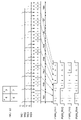
- FIG. 5 is a diagram showing an example of the light distribution image data IMG_LD, the serial interface signal SerIF, and the PWM control signal PWM_PIX.
- the number of pixels in the light distribution image data IMG_LD that is, the number n of light emitting pixels of the LED array 210 is four.
- the four pixels be p1 to p4.
- the pixel values of the plurality of pixels p1 to p4 of the light distribution image data IMG_LD change in (m+1) gradations.
- m 8 and the pixel values can be 9 gradations from 0 to 8.
- the pixel values of the four pixels p1 to p4 of the light distribution image data IMG_LD are 4, 3, 6, and 2, respectively.
- the serial interface signal SerIF includes m time slots TS1 to TSm. Each time slot contains n bits. Each pixel of the light distribution image data IMG_LD is assigned to a corresponding one of the n bits in each of the plurality of time slots. For example, the first pixel p1 is assigned to the leftmost bit of time slot TS, the second pixel p2 to the second bit from the left, and the jth pixel pj to the jth from the left.
- An intermediate code MCj representing the pixel value of pixel pj is stored in the j-th bit of m time slots TS1 to TSm.
- the intermediate code MCj is preferably a right-justified or left-justified thermometer code.
- the intermediate code MCj may be a code in which 1 bits are centrally concentrated.
- serial interface signal SerIF generated by the light distribution controller 300 .
- the feedback signal FB has the same format as the serial interface signal SerIF.
- the interface circuit 220 decodes this serial interface signal SerIF and generates a plurality of PWM control signals PWM_PIX1 to PWM_PIXn.
- interface circuit 220 includes a decoder 222 .
- the decoder 222 generates the PWM control signal PWM_PIXj to be supplied to the j-th light-emitting pixel PIXj by combining the j-th bit of each of the m time slots TS1 to TSm.
- a decoder 222 generates PWM control signals PWM_PIX1 to PWM_PIXn for all pixels.
- the luminance (time average value) of the j-th light-emitting pixel PIXj is the same as that of the pixel pj corresponding to the original light distribution image data IMG_LD. according to the value.
- the decoder 330 restores the PWM control signal PWM_PIXz of the target pixel from the feedback signal FB.
- feedback signal FB has the same format as serial interface signal SerIF, so decoder 330 is configured to have the same functionality as decoder 222 of interface circuit 220 . That is, the decoder 330 receives the feedback signal FB instead of the serial interface signal SerIF, and generates the PWM control signal PWM_PIXz for the pixel of interest.
- the decoder 330 combines the z-th bits of each of the m time slots TS1 to TSm included in the feedback signal FB to generate a PWM control signal to be supplied to the z-th light-emitting pixel PIXz, which is the pixel of interest. Generate PWM_PIXz'.
- the pixel of interest is not limited to one, and may be all pixels.
- the decoder 330 restores the PWM control signals PWM_PIX1' to PWM_PIXn' for all pixels, like the decoder 222 of the interface circuit 220.
- the abnormality detector 340 can know the waveform (expected waveform) of the PWM control signal PWM_PIXz to be generated inside the patterning device 200 based on the light distribution image data IMG_LD. For example, if the intermediate code MC generated by the pulse width modulator 322 of FIG. 4 is a thermometer code, the thermometer code represents the expected waveform of the PWM control signal PWM_PIXz. If the waveform of the PWM control signal PWM_PIXz' restored by the decoder 330 matches the expected waveform, it can be determined to be normal, and if it does not match, it can be determined to be abnormal. Matching or mismatching of the waveforms may be performed by comparing the pulse widths, or by comparing the lengths of the high section and the low section.
- FIG. 6 is a block diagram showing a configuration example (340A) of the anomaly detector 340.
- the anomaly detector 340A includes a TMU (time measurement unit) 342 and a determination section 344.
- the TMU 342 measures the length of one or both of the high section T L and the low section T L of the PWM control signal PWM_PIXz'.
- the determination unit 344 generates expected values of the times T H and T L measured by the TMU 342 based on the pixel values of the corresponding pixels in the light distribution image data IMG_LD. Then, the determination unit 344 determines whether the time actually measured by the TMU 342 matches or does not match the expected value. If they do not match, the determination unit 344 asserts (for example, high level) the abnormality detection signal ERR.
- the abnormality detection signal ERR may be an interrupt signal, or may be data including the number of a pixel in which an abnormality has occurred.
- the serial interface signal SerIF which is the output of the interface circuit 320
- the decoder 330 reproduces the PWM control signal PWM_PIX. Therefore, it is possible to detect a state in which an error occurs in the interface circuit 320 and a correct serial interface signal SerIF cannot be generated.
- the serial interface signal SerIF is normal at the output end of the interface circuit 320
- the serial interface signal SerIF received by the interface circuit 220 may be garbled due to waveform distortion and noise during transmission on the serial signal line 202. have a nature.
- the extraction position of the feedback signal FB is brought closer to the interface circuit 220, the feedback signal FB will be garbled like the serial interface signal SerIF.
- the abnormality detector 340 can determine that it is abnormal.
- patterning device 200 may include a light source that produces a beam with a uniform intensity distribution and a spatial light modulator that patterns the intensity distribution of the light source.
- spatial light modulators include DMDs (Digital Micromirror Devices) and liquid crystal panels.
- Modification 2 The format of the serial interface signal SerIF transmitted from the interface circuit 320 to the patterning device 200 is not limited to that illustrated in FIG.
- the configuration and determination method of the abnormality detector 340 are not limited to those of FIG. 6 either.
- the TMU is used to measure the time in FIG. 6, the PWM control signal PWM_PIXz' may be converted into a bit string and the bit string pattern may be compared with the expected value pattern.
- the present invention relates to a vehicle lamp.
- DESCRIPTION OF SYMBOLS 100... Lamp system, 102... Upper controller, 200... Patterning device, 202... Serial signal line, 210... LED array, 220... Interface circuit, 300... Light distribution controller, 302... Vehicle bus interface, 310... Rendering processing part, 320 ... interface circuit, 322 ... pulse width modulator, 324 ... serializer, 330 ... decoder, 340 ... abnormality detector, 342 ... TMU, 344 ... determination unit.
Landscapes
- Engineering & Computer Science (AREA)
- Mechanical Engineering (AREA)
- Lighting Device Outwards From Vehicle And Optical Signal (AREA)
Priority Applications (1)
| Application Number | Priority Date | Filing Date | Title |
|---|---|---|---|
| JP2023530415A JPWO2022270415A1 (https=) | 2021-06-22 | 2022-06-16 |
Applications Claiming Priority (2)
| Application Number | Priority Date | Filing Date | Title |
|---|---|---|---|
| JP2021103590 | 2021-06-22 | ||
| JP2021-103590 | 2021-06-22 |
Publications (1)
| Publication Number | Publication Date |
|---|---|
| WO2022270415A1 true WO2022270415A1 (ja) | 2022-12-29 |
Family
ID=84544879
Family Applications (1)
| Application Number | Title | Priority Date | Filing Date |
|---|---|---|---|
| PCT/JP2022/024219 Ceased WO2022270415A1 (ja) | 2021-06-22 | 2022-06-16 | 配光コントローラおよび車両用灯具システム |
Country Status (2)
| Country | Link |
|---|---|
| JP (1) | JPWO2022270415A1 (https=) |
| WO (1) | WO2022270415A1 (https=) |
Cited By (1)
| Publication number | Priority date | Publication date | Assignee | Title |
|---|---|---|---|---|
| WO2024172125A1 (ja) * | 2023-02-17 | 2024-08-22 | 株式会社小糸製作所 | 車両用灯具システム、配光可変ランプのコントローラ、制御方法、プログラム |
Citations (2)
| Publication number | Priority date | Publication date | Assignee | Title |
|---|---|---|---|---|
| WO2017018128A1 (ja) * | 2015-07-30 | 2017-02-02 | 株式会社小糸製作所 | 点灯回路、車両用灯具 |
| WO2019198604A1 (ja) * | 2018-04-10 | 2019-10-17 | 株式会社小糸製作所 | 車両用灯具およびその点灯回路、ドライバ回路、ドライバ一体化光源 |
-
2022
- 2022-06-16 JP JP2023530415A patent/JPWO2022270415A1/ja active Pending
- 2022-06-16 WO PCT/JP2022/024219 patent/WO2022270415A1/ja not_active Ceased
Patent Citations (2)
| Publication number | Priority date | Publication date | Assignee | Title |
|---|---|---|---|---|
| WO2017018128A1 (ja) * | 2015-07-30 | 2017-02-02 | 株式会社小糸製作所 | 点灯回路、車両用灯具 |
| WO2019198604A1 (ja) * | 2018-04-10 | 2019-10-17 | 株式会社小糸製作所 | 車両用灯具およびその点灯回路、ドライバ回路、ドライバ一体化光源 |
Cited By (1)
| Publication number | Priority date | Publication date | Assignee | Title |
|---|---|---|---|---|
| WO2024172125A1 (ja) * | 2023-02-17 | 2024-08-22 | 株式会社小糸製作所 | 車両用灯具システム、配光可変ランプのコントローラ、制御方法、プログラム |
Also Published As
| Publication number | Publication date |
|---|---|
| JPWO2022270415A1 (https=) | 2022-12-29 |
Similar Documents
| Publication | Publication Date | Title |
|---|---|---|
| US12232227B2 (en) | High speed image refresh system | |
| KR102405205B1 (ko) | 높은 리프레시 레이트 led 어레이를 위한 동적 픽셀 진단들 | |
| KR102650543B1 (ko) | 데이터 관리가 감소된 대형 led 어레이 | |
| EP3459790B1 (en) | Apparatus and method for controlling adb-mode vehicle headlamp | |
| WO2022270415A1 (ja) | 配光コントローラおよび車両用灯具システム | |
| WO2022270414A1 (ja) | ランプコントローラおよび車両用灯具システム | |
| KR102331664B1 (ko) | 고속 이미지 리프레시 시스템 | |
| US12617333B2 (en) | Lamp controller and automotive lamp system |
Legal Events
| Date | Code | Title | Description |
|---|---|---|---|
| 121 | Ep: the epo has been informed by wipo that ep was designated in this application |
Ref document number: 22828332 Country of ref document: EP Kind code of ref document: A1 |
|
| WWE | Wipo information: entry into national phase |
Ref document number: 2023530415 Country of ref document: JP |
|
| NENP | Non-entry into the national phase |
Ref country code: DE |
|
| 122 | Ep: pct application non-entry in european phase |
Ref document number: 22828332 Country of ref document: EP Kind code of ref document: A1 |