WO2022269670A1 - Indoor unit of air conditioning device - Google Patents
Indoor unit of air conditioning device Download PDFInfo
- Publication number
- WO2022269670A1 WO2022269670A1 PCT/JP2021/023355 JP2021023355W WO2022269670A1 WO 2022269670 A1 WO2022269670 A1 WO 2022269670A1 JP 2021023355 W JP2021023355 W JP 2021023355W WO 2022269670 A1 WO2022269670 A1 WO 2022269670A1
- Authority
- WO
- WIPO (PCT)
- Prior art keywords
- indoor unit
- housing
- discharge pipe
- drain pan
- switching valve
- Prior art date
Links
- 238000004378 air conditioning Methods 0.000 title abstract description 4
- 239000007788 liquid Substances 0.000 claims abstract description 18
- XLYOFNOQVPJJNP-UHFFFAOYSA-N water Substances O XLYOFNOQVPJJNP-UHFFFAOYSA-N 0.000 claims description 107
- 238000004891 communication Methods 0.000 abstract description 5
- 238000005406 washing Methods 0.000 description 21
- 239000003507 refrigerant Substances 0.000 description 17
- 238000010586 diagram Methods 0.000 description 13
- 238000004140 cleaning Methods 0.000 description 9
- 238000007599 discharging Methods 0.000 description 3
- 238000000034 method Methods 0.000 description 3
- 239000000126 substance Substances 0.000 description 3
- 241000233866 Fungi Species 0.000 description 2
- 230000005494 condensation Effects 0.000 description 2
- 238000009833 condensation Methods 0.000 description 2
- 238000001816 cooling Methods 0.000 description 2
- 239000000428 dust Substances 0.000 description 2
- 238000010438 heat treatment Methods 0.000 description 2
- 238000012986 modification Methods 0.000 description 2
- 230000004048 modification Effects 0.000 description 2
- 239000010802 sludge Substances 0.000 description 2
- 239000007787 solid Substances 0.000 description 2
- 239000002904 solvent Substances 0.000 description 2
- 239000003795 chemical substances by application Substances 0.000 description 1
- 239000012459 cleaning agent Substances 0.000 description 1
- 238000003912 environmental pollution Methods 0.000 description 1
- 230000003472 neutralizing effect Effects 0.000 description 1
- 239000003921 oil Substances 0.000 description 1
- 238000005057 refrigeration Methods 0.000 description 1
Images


Classifications
-
- F—MECHANICAL ENGINEERING; LIGHTING; HEATING; WEAPONS; BLASTING
- F24—HEATING; RANGES; VENTILATING
- F24F—AIR-CONDITIONING; AIR-HUMIDIFICATION; VENTILATION; USE OF AIR CURRENTS FOR SCREENING
- F24F13/00—Details common to, or for air-conditioning, air-humidification, ventilation or use of air currents for screening
- F24F13/22—Means for preventing condensation or evacuating condensate
Definitions
- the present disclosure relates to an indoor unit of an air conditioner provided with two discharge paths from a drain pan.
- the drain water generated on the surface of the heat exchanger is often stored in the drain pan and discharged from the drain pan through the drain pipe to the outside of the indoor unit.
- the drain water contains dust, mold, fungi, and the like adhering to the surface of the heat exchanger, such dust, mold, fungi, and the like are also accumulated in the drain pan.
- Patent Literature 1 an air conditioner for keeping the inside of the drain pan in good sanitary conditions.
- the indoor unit of the air conditioner described in Patent Document 1 includes a drain pump that sucks up the drain water stored in the drain pan, and a drain pipe that discharges the drain water sucked up by the drain pump to the outside. Further, the indoor unit of Patent Document 1 has a first flow path that communicates with the drain pipe via the drain pump from the drain pan, and a second flow path that communicates with the drain pipe via the branch pipe from the drain pan. The first channel and the second channel are switched by a channel switching valve.
- the present disclosure has been made against the background of the problems described above, and provides an indoor unit of an air conditioner that improves the ability to discharge cleaning water from a drain pan.
- the indoor unit of the air conditioner includes a housing, a first discharge port provided in the housing and communicating between the inside of the housing and the outside of the housing, and the housing inside the housing.
- a drain pan that is provided in the lower part of the indoor heat exchanger inside the housing and receives liquid that drops from the indoor heat exchanger; and inside the housing, from the drain pan a route switching valve through which the discharged liquid passes; a first discharge pipe provided between the route switching valve and the first discharge port through which the liquid passes; and a first discharge pipe provided separately from the first discharge pipe. and a second discharge pipe connected to the path switching valve, the path switching valve connecting either the first discharge pipe or the second discharge pipe to the drain pan.
- the liquid discharged from the drain pan can pass through the first discharge pipe or the second discharge pipe after passing through the path switching valve. Therefore, the liquid can be discharged from the drain pan through two paths. Therefore, one of the two paths can be used for discharging washing water, and the discharging performance of washing water is improved.
- FIG. 1 is a schematic diagram showing an example of a circuit configuration of an air conditioner according to Embodiment 1;
- FIG. 2 is a perspective view showing an example of the appearance of the indoor unit of the air conditioner according to Embodiment 1.
- FIG. 2 is a perspective view showing an example of the interior of the indoor unit of the air conditioner according to Embodiment 1.
- FIG. 2 is a schematic diagram showing part of the interior of the indoor unit of the air conditioner according to Embodiment 1.
- FIG. FIG. 2 is a schematic diagram showing an example of the structure of the path switching valve according to Embodiment 1;
- FIG. 2 is a schematic diagram showing an example of the structure of the path switching valve according to Embodiment 1;
- FIG. 1 is a schematic diagram showing an example of the structure of the path switching valve according to Embodiment 1;
- FIG. 8 is a schematic diagram showing an example of the structure of a water level sensor and a path switching valve according to Embodiment 2;
- FIG. 7 is a schematic diagram showing part of the interior of the indoor unit of the air conditioner according to Embodiment 2;
- FIG. 8 is a functional block diagram showing an example of functions of a control device according to Embodiment 2;
- 9 is a flow chart showing an example of operation when a water level sensor according to Embodiment 2 detects a value equal to or greater than a threshold;
- an embodiment of an indoor unit of an air conditioner according to the present disclosure will be described below with reference to the drawings.
- the present disclosure is not limited to the following embodiments, and various modifications can be made without departing from the gist of the present disclosure.
- the present disclosure includes all combinations of configurations that can be combined among the configurations shown in the following embodiments.
- the indoor units shown in the drawings are examples of the indoor units of the air conditioner of the present disclosure, and the indoor units shown in the drawings do not limit the applicable devices of the present disclosure.
- terms representing directions for example, “up”, “down”, “right”, “left”, “front”, “back”, etc.
- the same reference numerals denote the same or corresponding parts, which are common throughout the specification. In each drawing, the relative dimensional relationship, shape, etc. of each component may differ from the actual one.
- the X direction indicates the horizontal direction of the indoor unit, and the arrow indicates the direction from right to left.
- the Y direction indicates the front-to-rear direction of the indoor unit, and arrows indicate the direction from the front to the rear.
- the Z direction indicates the vertical direction of the indoor unit, and an arrow indicates the upward direction.
- FIG. 1 is a schematic diagram showing an example of a circuit configuration of an air conditioner 100 according to Embodiment 1.
- the air conditioner 100 is a device that adjusts air in an indoor space in which the indoor unit 1 is arranged.
- the indoor unit 1 is provided with an indoor heat exchanger 2 , an indoor fan 3 , an expansion section 8 , and a control device 40 .
- the outdoor unit 111 is provided with a compressor 114 , a channel switching device 115 , an outdoor heat exchanger 112 , and an outdoor fan 113 .
- the compressor 114, the flow switching device 115, the outdoor heat exchanger 112, the expansion section 8, and the indoor heat exchanger 2 are connected by refrigerant pipes 116 to form a refrigerant circuit through which the refrigerant flows.
- air conditioning using a refrigeration cycle is performed by circulating the refrigerant in the refrigerant circuit.
- the compressor 114 sucks the low-temperature, low-pressure refrigerant, compresses the sucked refrigerant, and discharges the high-temperature, high-pressure refrigerant.
- the flow switching device 115 switches the direction in which the refrigerant flows in the refrigerant circuit.
- the channel switching device 115 is, for example, a four-way valve.
- the outdoor fan 113 sends the air in the space where the outdoor unit 111 is arranged to the outdoor heat exchanger 112 .
- the outdoor heat exchanger 112 exchanges heat between the refrigerant and the air sent by the outdoor fan 113 .
- the outdoor heat exchanger 112 acts as a condenser during cooling operation and acts as an evaporator during heating operation.
- the indoor blower 3 sends the air in the space where the indoor unit 1 is arranged to the indoor heat exchanger 2 .
- the indoor heat exchanger 2 exchanges heat between the refrigerant and the air sent by the indoor blower 3 .
- the indoor heat exchanger 2 acts as an evaporator during cooling operation, and acts as a condenser during heating operation.
- the expansion unit 8 is a pressure reducing valve or an expansion valve that reduces the pressure of the refrigerant to expand it.
- the expansion part 8 is, for example, an electronic expansion valve whose opening is adjusted.
- a controller 40 is provided in the air conditioner 100 .
- the control device 40 includes, for example, a microcomputer, software executed on an arithmetic device such as a CPU (Central Processing Unit), hardware such as a circuit device that realizes various functions, and the like, and controls the operation of the entire air conditioner 100. Control.
- the control device 40 controls the compressor frequency of the compressor 114, the opening degree of the expansion section 8, the rotation speeds (including ON/OFF) of the indoor fan 3 and the outdoor fan 113, and It controls switching of the channel switching device 115 and the like.
- the control device 40 also controls switching of the path switching valve 20, which will be described later.
- the controller 40 is provided in the indoor unit 1 in FIG. 1
- the controller 40 may be provided in the outdoor unit 111 instead of the indoor unit 1 .
- the control device 40 may be provided as a separate body from the indoor unit 1 and the outdoor unit 111 .
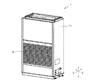
- FIG. 2 is a perspective view showing an example of the appearance of the indoor unit 1 of the air conditioner 100 according to Embodiment 1.
- FIG. 3 is a perspective view showing an example of the interior of the indoor unit 1 of the air conditioner 100 according to Embodiment 1.
- FIG. 4 is a schematic diagram showing part of the interior of the indoor unit 1 of the air conditioner 100 according to Embodiment 1. As shown in FIG.
- the indoor unit 1 is of a floor standing type, and includes a housing 1a that forms an outer shape.
- a panel 6 provided with a large number of slits is attached to the housing 1a.
- an indoor heat exchanger 2 Inside the housing 1a, as shown in FIG. 3, an indoor heat exchanger 2, an indoor fan 3, a filter 7, a drain pan 5, and a control box 4 having a control device 40 are accommodated.
- 2 and 3 show the floor-standing type indoor unit 1, the indoor unit 1 is not limited to the floor-standing type.
- the indoor unit 1 may be an indoor unit of an air conditioner provided with an indoor fan, an indoor heat exchanger, and a drain pan, and may be of a ceiling-embedded type, a ceiling-suspended type, a ducted type, or a wall-mounted type.
- the indoor fan 3 has a fan motor 3a, a fan 3b, and a fan housing 3c.
- the fan motor 3a rotates the fan 3b.
- the fan 3b is, for example, a sirocco fan or a turbofan.
- the fan housing 3c rotatably supports the fan 3b.
- a filter 7 and an indoor heat exchanger 2 are arranged below the indoor fan 3 .
- a filter 7 is provided between the panel 6 and the indoor heat exchanger 2 .
- the filter 7 filters the air flowing in through the slits of the panel 6 and is provided so as to be combined with the indoor heat exchanger 2 .
- By operating the indoor blower 3, the air in the space where the indoor unit 1 is arranged is sucked into the indoor unit 1 through the panel 6.
- - ⁇ Air sucked into the interior of the indoor unit 1 flows into the indoor heat exchanger 2 after being filtered by the filter 7 .
- a refrigerant pipe 116 (not shown) is connected to the indoor heat exchanger 2, and heat exchange is performed between the refrigerant flowing through the refrigerant pipe 116 and the filtered air.
- a drain pan 5 is provided below the indoor heat exchanger 2 . Condensed water and dew condensation water are generated in the indoor heat exchanger 2 during operation of the air conditioner 100 .
- the drain pan 5 stores such condensed water and dew condensation water that fall from the indoor heat exchanger 2 located above. In this specification, water such as condensed water and condensed water generated in the indoor heat exchanger 2 is referred to as drain water. A route through which drain water is discharged from the drain pan 5 will be described later.
- a control box 4 is provided below the drain pan 5 .
- a control device 40 is housed inside the control box 4 . Although the control box 4 is provided below the drain pan 5 in FIG. 3 , the control box 4 may be provided above the drain pan 5 or above the indoor heat exchanger 2 . Also, the control box 4 may be provided separately from the indoor unit 1 .
- a path switching valve 20 is provided below the drain pan 5 .
- the path switching valve 20 has a first opening 22 , a second opening 23 and a third opening 24 .
- a drain pan 5 is connected to the first opening 22 . Drain water from the drain pan 5 flows into the path switching valve 20 through the first opening 22 .
- a first discharge pipe 9 is connected to the second opening 23 .
- the first discharge pipe 9 is, for example, a flexible drain hose.
- the other end of the first discharge pipe 9 that is not connected to the second opening 23 is connected to the first discharge port 10 .
- the first discharge port 10 is provided in the housing 1a and communicates the inside of the housing 1a with the outside of the housing 1a. Therefore, the first discharge pipe 9 communicates with the outside of the housing 1 a, that is, the outside of the indoor unit 1 through the first discharge port 10 .
- a second discharge pipe 25 is connected to the third opening 24 .
- the second discharge pipe 25 is shorter than the first discharge pipe 9, and the other end not connected to the third opening 24 is not connected to anything.
- a flexible drain hose can be connected to the free end of the second discharge pipe 25 .
- a storage tank capable of storing the liquid discharged from the second discharge pipe 25 can be connected to the end of the second discharge pipe 25 to which nothing is connected.
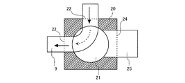
- FIGS. 5 and 6 are schematic diagrams showing an example of the structure of the path switching valve 20 according to Embodiment 1.
- the path switching valve 20 is a three-way valve having a valve body 21 .
- the path switching valve 20 has a first path provided between a first opening 22 and a second opening 23 that allows the drain pan 5 and the first discharge pipe 9 to communicate with each other.
- solid line and broken line arrows indicate paths in which the drain pan 5 and the first discharge pipe 9 are in communication.
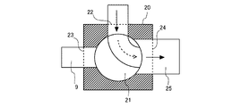
- the path switching valve 20 also has a second path provided between the first opening 22 and the third opening 24 that allows the drain pan 5 and the second discharge pipe 25 to communicate with each other.
- solid line and broken line arrows indicate paths in which the drain pan 5 and the second discharge pipe 25 are in communication.
- the valve body 21 is switched between a first state in which the first opening 22 and the second opening 23 are communicated and a second state in which the first opening 22 and the third opening 24 are communicated.
- the path switching valve 20 connects the first path by setting the valve body 21 to the first state, and connects the second path by setting the valve body 21 to the second state.
- the valve body 21 is set to the first state, and the first path is open. In the first state, there is no communication between the first opening 22 and the third opening 24, and the second path is blocked.
- the valve body 21 is set to the second state, and the second path is open. In the second state, there is no communication between the first opening 22 and the second opening 23, and the first path is blocked.
- discharge of drain water Next, discharge of drain water will be described with reference to FIG.
- the valve body 21 of the path switching valve 20 is set to the first state, and the first path is communicated. Drain water stored in the drain pan 5 flows into the path switching valve 20 through the first opening 22 . Drain water that has flowed into the path switching valve 20 flows through the second opening 23 into the first discharge pipe 9 connected to the second opening 23 . The drain water that has flowed into the first discharge pipe 9 is discharged from the indoor unit 1 through the first discharge port 10 .
- the valve body 21 of the path switching valve 20 is set to the second state.
- the wash water that has washed the indoor heat exchanger 2 is stored in the drain pan 5 and then flows into the path switching valve 20 through the first opening 22 .
- the wash water that has flowed into the path switching valve 20 flows through the third opening 24 and into the second discharge pipe 25 connected to the third opening 24 .
- the wash water flowing into the second discharge pipe 25 is discharged from the second discharge pipe 25 . Therefore, when cleaning the indoor heat exchanger 2 , a drain hose is temporarily connected to the second discharge pipe 25 so that the cleaning water can be discharged to the outside of the indoor unit 1 .
- a storage tank may be temporarily connected to the second discharge pipe 25 to recover the cleaning water.
- the wash water discharged from the second discharge pipe 25 is discharged from the indoor unit 1 by a drain hose or a storage tank connected to the second discharge pipe 25 .
- the means for discharging the wash water from the second discharge pipe 25 to the outside of the indoor unit 1 is not limited to the drain hose or the storage tank.
- a drain hose and a storage tank may be combined, or a pipe may be used instead of the drain hose.
- the channel cross-sectional area of the second discharge pipe 25 is larger than the channel cross-sectional area of the first discharge pipe 9 so that a large amount of washing water can pass through.
- the diameter of the second discharge pipe 25 is larger than the diameter of the first discharge pipe 9, so the cross-sectional area of the second discharge pipe 25 is equal to that of the first discharge pipe 9 larger than the cross-sectional area of the flow path.
- the path switching valve 20 can be switched manually or electrically. Further, the switching of the path switching valve 20 can be controlled by the control device 40 .
- the path switching valve 20 is not limited to a three-way valve, and may be configured by combining two-way valves. Also, in this specification, when there is no need to distinguish between drain water and wash water, drain water and wash water are referred to as liquid.
- the indoor unit 1 of the air-conditioning apparatus 100 of Embodiment 1 includes the housing 1a and the first discharge port provided in the housing 1a for communicating the inside of the housing 1a and the outside of the housing 1a. 10, an indoor heat exchanger 2 housed inside the housing 1a, and a drain pan 5 that is provided below the indoor heat exchanger 2 inside the housing 1a and receives liquid that drops from the indoor heat exchanger 2. and a route switching valve 20 through which the liquid discharged from the drain pan 5 passes inside the housing 1a, and a first discharge pipe provided between the route switching valve 20 and the first discharge port 10 through which the liquid passes. 9 and a second discharge pipe 25 provided separately from the first discharge pipe 9 and connected to the path switching valve 20 .
- the path switching valve 20 allows one of the first discharge pipe 9 and the second discharge pipe 25 to communicate with the drain pan 5 .
- the drain water generated in the indoor heat exchanger 2 can be discharged from the first discharge pipe 9, and the washing water used to wash the indoor heat exchanger 2 can be discharged from the second discharge pipe 25.
- a cleaning agent such as an alkaline solvent may be used. Washing water containing an alkaline solvent or the like must sometimes be neutralized with a neutralizing agent before being discharged in order to prevent environmental pollution.
- the wash water used to wash the indoor heat exchanger 2 can be discharged from the second discharge pipe 25, so that the wash water can be easily recovered and neutralized. Therefore, washing water dischargeability is improved.
- the washing water used to wash the indoor heat exchanger 2 may contain substances such as solids, sludge, and oil. Therefore, when the cleaning water is discharged from the drain water discharge path, these substances may not be discharged, and the drain water discharge path may be blocked.
- the washing water since the washing water can be discharged through a path different from that of the drain water, the washing water does not clog the drain water discharge path. Therefore, the washing water can be discharged without worrying about impairing the drainage performance of the drain water, so that the washing water can be easily drained. Therefore, washing water dischargeability is improved.
- the channel cross-sectional area of the second discharge pipe 25 is larger than the channel cross-sectional area of the first discharge pipe 9 . According to this configuration, even if the washing water contains substances such as solid matter, sludge, oil, etc., the passage cross-sectional area of the second discharge pipe 25 is large, so that the discharge path of the washing water is blocked. can be prevented from becoming. In addition, since the flow passage cross-sectional area of the second discharge pipe 25 is large, a large amount of washing water can be discharged. Therefore, the ability to discharge cleaning water from the indoor heat exchanger 2 is further improved.
- Embodiment 2 Next, the indoor unit 1 of the air conditioner 100 according to Embodiment 2 will be described.
- the indoor unit 1 of the air conditioner 100 of Embodiment 2 differs from the indoor unit 1 of the air conditioner 100 of Embodiment 1 in that a water level sensor 12 is provided.
- the configurations of the water level sensor 12 and the indoor unit 1 of the second embodiment will be described below, focusing on differences from the first embodiment. Also, descriptions of parts common to the first embodiment will be omitted.
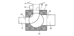
- FIG. 7 is a schematic diagram showing an example of structures of the water level sensor 12 and the path switching valve 20 according to the second embodiment.
- FIG. 8 is a schematic diagram showing part of the interior of the indoor unit 1 of the air conditioner 100 according to Embodiment 2.
- the water level sensor 12 may be provided between the drain pan 5 and the path switching valve 20 as shown in FIG. 7, or may be provided inside the drain pan 5 as shown in FIG.
- the water level sensor 12 may be any sensor that can detect the state of the water level.
- the water level sensor 12 is a non-contact, magnetic or laser type switch.
- the water level sensor 12 may be a contact-type floating switch.
- FIG. 8 shows the configuration of the indoor unit 1 when the indoor unit 1 is provided with the water level sensor 12 .
- the water level sensor 12 is provided inside the drain pan 5 in FIG. 8
- the water level sensor 12 may be provided between the drain pan 5 and the path switching valve 20 .
- a second discharge port 30 is provided in the housing 1a.
- the second outlet 30 communicates the inside of the housing 1a with the outside of the housing 1a.
- a second outlet drain hose 31 is connected between the second outlet pipe 25 and the second outlet 30 . Therefore, the second discharge pipe 25 communicates with the outside of the housing 1 a, that is, the outside of the indoor unit 1 through the second discharge port 30 .
- the wash water discharged from the second discharge pipe 25 is discharged from the indoor unit 1 through the second discharge port drain hose 31 and the second discharge port 30 .
- FIG. 9 is a functional block diagram showing an example of functions of the control device 40 according to the second embodiment.
- FIG. 10 is a flow chart showing an example of the operation when the water level sensor 12 according to Embodiment 2 detects a value equal to or greater than the threshold.
- the controller 40 has a water level at which the drain pan 5 may overflow as a threshold.
- the threshold does not have to be the water level at which the drain pan 5 may overflow, and the threshold may be a water level lower than the water level at which the drain pan 5 overflows.
- the valve body 21 of the path switching valve 20 is set to the first state, and the first path communicates.
- a state may occur in which the drain water cannot be discharged to the outside of the indoor unit 1 while the air conditioner 100 is in operation.
- the first discharge pipe 9 is blocked and the drain water cannot be discharged from the indoor unit 1 .
- the drain pan 5 may overflow.
- FIG. 10 shows the operation of the control device 40 from the time when the value of the water level is notified from the water level sensor 12 to the control device 40 .
- the control device 40 determines whether or not the water level sensor 12 has detected a value equal to or greater than the threshold (step ST1).
- step ST1: YES the valve body 21 of the path switching valve 20 is switched to the second state, the second path is communicated (step ST2), and the process is performed. finish.
- step ST1: NO the process ends without doing anything.
- the second discharge port drain hose 31 is connected between the second discharge pipe 25 and the second discharge port 30 as described above.
- the control device 40 switches the valve body 21 of the path switching valve 20 to the second state to open the second path. Therefore, the drain water of the drain pan 5 is discharged from the second discharge pipe 25 and discharged from the indoor unit 1 through the second discharge port drain hose 31 and the second discharge port 30 .
- the indoor unit 1 of the air conditioner 100 according to Embodiment 2 described above includes the water level sensor 12 provided between the drain pan 5 and the path switching valve 20 . Therefore, it can be detected that the liquid is not discharged from the path switching valve 20 . Therefore, it is possible to detect in advance that the drain pan 5 may overflow.
- the indoor unit 1 of the air conditioner 100 according to Embodiment 2 includes a water level sensor 12 provided in the drain pan 5 . Therefore, it can be detected that the liquid is not discharged from the drain pan 5 . Therefore, it is possible to detect in advance that the drain pan 5 may overflow.
- the path switching valve 20 connects the second discharge pipe 25 to the drain pan 5 when the water level sensor 12 detects a value equal to or higher than the threshold. Therefore, the drain water is discharged from the second discharge pipe 25 when the drain pan 5 is likely to overflow. Therefore, overflow of the drain pan 5 can be automatically avoided.
- the indoor unit 1 of the air conditioner 100 is not limited to the above-described Embodiment 1 and Embodiment 2, and is within the scope of the gist. Various modifications and applications are possible within.
- the water level sensor 12 of the second embodiment may be provided in the indoor unit 1 shown in the first embodiment.
- 1 indoor unit 1a housing, 2 indoor heat exchanger, 3 indoor blower, 3a fan motor, 3b fan, 3c fan housing, 4 control box, 5 drain pan, 6 panel, 7 filter, 8 expansion part, 9 first Discharge pipe, 10 first discharge port, 12 water level sensor, 20 path switching valve, 21 valve body, 22 first opening, 23 second opening, 24 third opening, 25 second discharge pipe, 30 second discharge port, 31 Second outlet drain hose, 40 control device, 100 air conditioner, 111 outdoor unit, 112 outdoor heat exchanger, 113 outdoor fan, 114 compressor, 115 flow switching device, 116 refrigerant piping.
Abstract
This indoor unit of an air conditioning device includes: a housing; a first discharge port provided in the housing and for communicating between the inside and outside of the housing; an indoor heat exchanger housed inside the housing; a drain pan provided inside the housing below the indoor heat exchanger and for receiving liquid dropped from the indoor heat exchanger; a path switching valve inside the housing and for letting liquid discharged from the drain pan pass therethrough; a first exhaust pipe provided between the path switching valve and the first discharge port and letting liquid pass therethrough; and a second exhaust pipe provided separately from the first exhaust pipe and connected to the path switching valve, the path switching valve brings one of the first and second exhaust pipes in communication with the drain pan.
Description
本開示は、ドレンパンからの排出経路を2つ備えた空気調和装置の室内機に関する。
The present disclosure relates to an indoor unit of an air conditioner provided with two discharge paths from a drain pan.
空気調和装置の室内機では、熱交換器の表面に発生したドレン水が、ドレンパンに貯留され、ドレンパンから排水配管を通って室内機の外に排出されることが多い。しかし、ドレン水には熱交換器の表面に付着した塵、カビ、及び菌等が含まれるため、こうした塵、カビ、及び菌等もドレンパンに貯留されることになる。このような事項を背景として、ドレンパン内の衛生状態を良好に保つための空気調和装置が提案されている(たとえば、特許文献1)。
In the indoor unit of an air conditioner, the drain water generated on the surface of the heat exchanger is often stored in the drain pan and discharged from the drain pan through the drain pipe to the outside of the indoor unit. However, since the drain water contains dust, mold, fungi, and the like adhering to the surface of the heat exchanger, such dust, mold, fungi, and the like are also accumulated in the drain pan. Against the background of such matters, there has been proposed an air conditioner for keeping the inside of the drain pan in good sanitary conditions (for example, Patent Literature 1).
特許文献1に記載された空気調和装置の室内機は、ドレンパンに貯留されたドレン水を吸い上げるドレンポンプと、ドレンポンプにより吸い上げられたドレン水を外部へと排出するための排水配管とを備える。また、特許文献1の室内機は、ドレンパンからドレンポンプを経由して排水配管に連通する第1の流路と、ドレンパンから分岐配管を経由して排水配管に連通する第2の流路とを有し、第1の流路と第2の流路は流路切替弁により切り替えられる。
The indoor unit of the air conditioner described in Patent Document 1 includes a drain pump that sucks up the drain water stored in the drain pan, and a drain pipe that discharges the drain water sucked up by the drain pump to the outside. Further, the indoor unit of Patent Document 1 has a first flow path that communicates with the drain pipe via the drain pump from the drain pan, and a second flow path that communicates with the drain pipe via the branch pipe from the drain pan. The first channel and the second channel are switched by a channel switching valve.
ところで、特許文献1に記載されているような、吸い込んだ空気を熱交換器で利用する空気調和装置の室内機では、空気に含まれた汚れ及び浮遊物が熱交換器の表面だけでなく内部にも蓄積されるため、熱交換器を含む室内機の内部を洗浄する場合がある。しかし、特許文献1のような、ドレンパンから排水配管までの流路が2つある室内機であっても、排出配管は1つであるため、室内機の内部を洗浄した洗浄水はドレンパンから排水配管を通って排出されることになる。つまり、従来の室内機では洗浄水のための排出経路が設けられておらず、洗浄水はドレン水と同じ排出経路でドレンパンから排出される。しかし、室内機の洗浄には多量の洗浄水を利用することがあり、洗浄水の排出が困難となる場合があった。
By the way, in an indoor unit of an air conditioner that utilizes sucked air in a heat exchanger, as described in Patent Document 1, dirt and suspended matter contained in the air are not only on the surface of the heat exchanger, but also inside the heat exchanger. Also, the inside of the indoor unit, including the heat exchanger, may be washed. However, even in an indoor unit that has two flow paths from the drain pan to the drain pipe, as in Patent Document 1, there is only one discharge pipe, so the washing water used to wash the inside of the indoor unit is drained from the drain pan. It will be discharged through the pipe. In other words, the conventional indoor unit is not provided with a discharge route for the wash water, and the wash water is discharged from the drain pan through the same discharge route as the drain water. However, a large amount of washing water is sometimes used for washing the indoor unit, and it is sometimes difficult to discharge the washing water.
本開示は、上記のような課題を背景としてなされたものであり、ドレンパンからの洗浄水の排出性を向上させた空気調和装置の室内機を提供するものである。
The present disclosure has been made against the background of the problems described above, and provides an indoor unit of an air conditioner that improves the ability to discharge cleaning water from a drain pan.
本開示に係る空気調和装置の室内機は、筐体と、前記筐体に設けられ、前記筐体の内部と前記筐体の外部を連通する第1排出口と、前記筐体の内部に収容される室内熱交換器と、前記筐体の内部で、前記室内熱交換器の下部に設けられ、前記室内熱交換器から落下する液体を受けるドレンパンと、前記筐体の内部で、前記ドレンパンから排出された前記液体が通過する経路切替弁と、前記経路切替弁と前記第1排出口との間に設けられ、前記液体が通過する第1排出管と、前記第1排出管とは別に設けられ、前記経路切替弁に接続された第2排出管とを備え、前記経路切替弁は、前記第1排出管及び前記第2排出管のいずれか一方を前記ドレンパンに連通させる。
The indoor unit of the air conditioner according to the present disclosure includes a housing, a first discharge port provided in the housing and communicating between the inside of the housing and the outside of the housing, and the housing inside the housing. a drain pan that is provided in the lower part of the indoor heat exchanger inside the housing and receives liquid that drops from the indoor heat exchanger; and inside the housing, from the drain pan a route switching valve through which the discharged liquid passes; a first discharge pipe provided between the route switching valve and the first discharge port through which the liquid passes; and a first discharge pipe provided separately from the first discharge pipe. and a second discharge pipe connected to the path switching valve, the path switching valve connecting either the first discharge pipe or the second discharge pipe to the drain pan.
本開示によれば、ドレンパンから排出された液体は、経路切替弁を通過したあと、第1排出管を通過することも、第2排出管を通過することもできる。このため、2つの経路によって、ドレンパンから液体を排出することができる。したがって、2つの経路のうちの1つの経路を洗浄水の排出用として使用することが可能となり、洗浄水の排出性が向上する。
According to the present disclosure, the liquid discharged from the drain pan can pass through the first discharge pipe or the second discharge pipe after passing through the path switching valve. Therefore, the liquid can be discharged from the drain pan through two paths. Therefore, one of the two paths can be used for discharging washing water, and the discharging performance of washing water is improved.
以下、本開示に係る空気調和装置の室内機の実施の形態を、図面を参照して説明する。本開示は、以下の実施の形態に限定されるものではなく、本開示の主旨を逸脱しない範囲で種々に変形することが可能である。また、本開示は、以下の各実施の形態に示す構成のうち、組合せ可能な構成のあらゆる組合せを含むものである。また、図面に示す室内機は、本開示の空気調和装置の室内機の一例を示すものであり、図面に示された室内機によって本開示の適用機器が限定されるものではない。また、以下の説明において、理解を容易にするために方向を表す用語(例えば「上」、「下」、「右」、「左」、「前」、「後」など)を適宜用いるが、これらは説明のためのものであって、本開示を限定するものではない。また、各図において、同一の符号を付したものは、同一の又はこれに相当するものであり、これは明細書の全文において共通している。なお、各図面では、各構成部材の相対的な寸法関係又は形状等が実際のものとは異なる場合がある。
An embodiment of an indoor unit of an air conditioner according to the present disclosure will be described below with reference to the drawings. The present disclosure is not limited to the following embodiments, and various modifications can be made without departing from the gist of the present disclosure. In addition, the present disclosure includes all combinations of configurations that can be combined among the configurations shown in the following embodiments. Also, the indoor units shown in the drawings are examples of the indoor units of the air conditioner of the present disclosure, and the indoor units shown in the drawings do not limit the applicable devices of the present disclosure. Also, in the following description, terms representing directions (for example, "up", "down", "right", "left", "front", "back", etc.) are used as appropriate for ease of understanding. They are intended to be illustrative and not limiting of the present disclosure. Also, in each figure, the same reference numerals denote the same or corresponding parts, which are common throughout the specification. In each drawing, the relative dimensional relationship, shape, etc. of each component may differ from the actual one.
また、以下の図において、X方向は、室内機の左右方向を示し、矢印により右から左方向を示すこととする。Y方向は、室内機の前後方向を示し、矢印により前から後ろ方向を示すこととする。Z方向は、室内機の上下方向を示し、矢印により下から上方向を示すこととする。
Also, in the following figures, the X direction indicates the horizontal direction of the indoor unit, and the arrow indicates the direction from right to left. The Y direction indicates the front-to-rear direction of the indoor unit, and arrows indicate the direction from the front to the rear. The Z direction indicates the vertical direction of the indoor unit, and an arrow indicates the upward direction.
実施の形態1.
図1は、実施の形態1に係る空気調和装置100の回路構成の一例を示す概略図である。図1に示すように、空気調和装置100は、室内機1が配置された室内空間の空気を調整する装置であり、室内機1と、冷媒配管116によって室内機1と接続される室外機111とを備えている。室内機1には、室内熱交換器2と、室内送風機3と、膨張部8と、制御装置40とが設けられている。室外機111には、圧縮機114と、流路切替装置115と、室外熱交換器112と、室外送風機113とが設けられている。Embodiment 1.
FIG. 1 is a schematic diagram showing an example of a circuit configuration of anair conditioner 100 according to Embodiment 1. FIG. As shown in FIG. 1, the air conditioner 100 is a device that adjusts air in an indoor space in which the indoor unit 1 is arranged. and The indoor unit 1 is provided with an indoor heat exchanger 2 , an indoor fan 3 , an expansion section 8 , and a control device 40 . The outdoor unit 111 is provided with a compressor 114 , a channel switching device 115 , an outdoor heat exchanger 112 , and an outdoor fan 113 .
図1は、実施の形態1に係る空気調和装置100の回路構成の一例を示す概略図である。図1に示すように、空気調和装置100は、室内機1が配置された室内空間の空気を調整する装置であり、室内機1と、冷媒配管116によって室内機1と接続される室外機111とを備えている。室内機1には、室内熱交換器2と、室内送風機3と、膨張部8と、制御装置40とが設けられている。室外機111には、圧縮機114と、流路切替装置115と、室外熱交換器112と、室外送風機113とが設けられている。
FIG. 1 is a schematic diagram showing an example of a circuit configuration of an
圧縮機114、流路切替装置115、室外熱交換器112、膨張部8及び室内熱交換器2が冷媒配管116により接続されて、冷媒が流れる冷媒回路が構成されている。空気調和装置100では、冷媒回路を冷媒が循環することで、冷凍サイクルを利用した空気調和が行われる。圧縮機114は、低温且つ低圧の状態の冷媒を吸入し、吸入した冷媒を圧縮して高温且つ高圧の状態の冷媒にして吐出する。流路切替装置115は、冷媒回路において冷媒が流れる方向を切り替える。流路切替装置115は、例えば四方弁である。室外送風機113は、室外熱交換器112に、室外機111が配置された空間の空気を送る。室外熱交換器112は、冷媒と室外送風機113により送られた空気との間で熱交換させる。室外熱交換器112は、冷房運転時には凝縮器として作用し、暖房運転時には蒸発器として作用する。
The compressor 114, the flow switching device 115, the outdoor heat exchanger 112, the expansion section 8, and the indoor heat exchanger 2 are connected by refrigerant pipes 116 to form a refrigerant circuit through which the refrigerant flows. In the air conditioner 100, air conditioning using a refrigeration cycle is performed by circulating the refrigerant in the refrigerant circuit. The compressor 114 sucks the low-temperature, low-pressure refrigerant, compresses the sucked refrigerant, and discharges the high-temperature, high-pressure refrigerant. The flow switching device 115 switches the direction in which the refrigerant flows in the refrigerant circuit. The channel switching device 115 is, for example, a four-way valve. The outdoor fan 113 sends the air in the space where the outdoor unit 111 is arranged to the outdoor heat exchanger 112 . The outdoor heat exchanger 112 exchanges heat between the refrigerant and the air sent by the outdoor fan 113 . The outdoor heat exchanger 112 acts as a condenser during cooling operation and acts as an evaporator during heating operation.
室内送風機3は、室内熱交換器2に、室内機1が配置された空間の空気を送る。室内熱交換器2は、冷媒と室内送風機3により送られた空気との間で熱交換させる。室内熱交換器2は、冷房運転時には蒸発器として作用し、暖房運転時には凝縮器として作用する。膨張部8は、冷媒を減圧して膨張する減圧弁又は膨張弁である。膨張部8は、例えば開度が調整される電子式膨張弁である。
The indoor blower 3 sends the air in the space where the indoor unit 1 is arranged to the indoor heat exchanger 2 . The indoor heat exchanger 2 exchanges heat between the refrigerant and the air sent by the indoor blower 3 . The indoor heat exchanger 2 acts as an evaporator during cooling operation, and acts as a condenser during heating operation. The expansion unit 8 is a pressure reducing valve or an expansion valve that reduces the pressure of the refrigerant to expand it. The expansion part 8 is, for example, an electronic expansion valve whose opening is adjusted.
空気調和装置100には、制御装置40が設けられている。制御装置40は、例えばマイクロコンピュータ、CPU(Central Processing Unit)などの演算装置上で実行されるソフトウェア、各種機能を実現する回路デバイスなどのハードウェア等で構成され、空気調和装置100全体の運転を制御する。例えば制御装置40は、空気調和装置100の運転内容等に基づき、圧縮機114の圧縮機周波数、膨張部8の開度、室内送風機3及び室外送風機113の回転数(ON/OFF含む)、ならびに流路切替装置115の切り替え等を制御する。また、制御装置40は、後述する経路切替弁20の切り替えも制御する。なお、図1では室内機1に制御装置40が設けられているが、制御装置40は、室内機1ではなく室外機111に設けられてもよい。また、制御装置40は、室内機1及び室外機111とは別体として設けられてもよい。
A controller 40 is provided in the air conditioner 100 . The control device 40 includes, for example, a microcomputer, software executed on an arithmetic device such as a CPU (Central Processing Unit), hardware such as a circuit device that realizes various functions, and the like, and controls the operation of the entire air conditioner 100. Control. For example, the control device 40 controls the compressor frequency of the compressor 114, the opening degree of the expansion section 8, the rotation speeds (including ON/OFF) of the indoor fan 3 and the outdoor fan 113, and It controls switching of the channel switching device 115 and the like. The control device 40 also controls switching of the path switching valve 20, which will be described later. In addition, although the controller 40 is provided in the indoor unit 1 in FIG. 1 , the controller 40 may be provided in the outdoor unit 111 instead of the indoor unit 1 . Also, the control device 40 may be provided as a separate body from the indoor unit 1 and the outdoor unit 111 .
(室内機1の構成)
図2~図4を参照しながら、実施の形態1に係る室内機1の構成について説明する。図2は、実施の形態1に係る空気調和装置100の室内機1の外観の一例を示す斜視図である。図3は、実施の形態1に係る空気調和装置100の室内機1の内部の一例を示す斜視図である。図4は、実施の形態1に係る空気調和装置100の室内機1の内部の一部を示す概略図である。 (Configuration of indoor unit 1)
The configuration of theindoor unit 1 according to Embodiment 1 will be described with reference to FIGS. 2 to 4. FIG. 2 is a perspective view showing an example of the appearance of the indoor unit 1 of the air conditioner 100 according to Embodiment 1. FIG. 3 is a perspective view showing an example of the interior of the indoor unit 1 of the air conditioner 100 according to Embodiment 1. FIG. FIG. 4 is a schematic diagram showing part of the interior of the indoor unit 1 of the air conditioner 100 according to Embodiment 1. As shown in FIG.
図2~図4を参照しながら、実施の形態1に係る室内機1の構成について説明する。図2は、実施の形態1に係る空気調和装置100の室内機1の外観の一例を示す斜視図である。図3は、実施の形態1に係る空気調和装置100の室内機1の内部の一例を示す斜視図である。図4は、実施の形態1に係る空気調和装置100の室内機1の内部の一部を示す概略図である。 (Configuration of indoor unit 1)
The configuration of the
図2に示すように、室内機1は、床置き型であり、外形を形成する筐体1aを備える。筐体1aには、多数のスリットが設けられたパネル6が取り付けられている。筐体1aの内部には、図3に示すように、室内熱交換器2と、室内送風機3と、フィルタ7と、ドレンパン5と、制御装置40を有する制御箱4が収容される。なお、図2及び図3では床置き型の室内機1を示しているが、室内機1は床置き型に限定されない。室内機1は、室内送風機、室内熱交換器、及びドレンパンを備えた空気調和装置の室内機であればよく、天井埋込み型、天井吊り型、ダクト型、又は壁掛け型であってもよい。
As shown in FIG. 2, the indoor unit 1 is of a floor standing type, and includes a housing 1a that forms an outer shape. A panel 6 provided with a large number of slits is attached to the housing 1a. Inside the housing 1a, as shown in FIG. 3, an indoor heat exchanger 2, an indoor fan 3, a filter 7, a drain pan 5, and a control box 4 having a control device 40 are accommodated. 2 and 3 show the floor-standing type indoor unit 1, the indoor unit 1 is not limited to the floor-standing type. The indoor unit 1 may be an indoor unit of an air conditioner provided with an indoor fan, an indoor heat exchanger, and a drain pan, and may be of a ceiling-embedded type, a ceiling-suspended type, a ducted type, or a wall-mounted type.
図3に示すように、室内送風機3は、ファンモータ3aと、ファン3bと、ファン筐体3cを有する。ファンモータ3aは、ファン3bを回転駆動させる。ファン3bは、例えば、シロッコファン又はターボファンである。ファン筐体3cはファン3bを回転可能に支持する。
As shown in FIG. 3, the indoor fan 3 has a fan motor 3a, a fan 3b, and a fan housing 3c. The fan motor 3a rotates the fan 3b. The fan 3b is, for example, a sirocco fan or a turbofan. The fan housing 3c rotatably supports the fan 3b.
室内送風機3の下方には、フィルタ7及び室内熱交換器2が配置される。フィルタ7は、パネル6と室内熱交換器2の間に設けられる。フィルタ7は、パネル6のスリットから流入する空気を濾過するものであり、室内熱交換器2に抱き合わせられるように設けられる。室内送風機3が運転することで、室内機1が配置された空間の空気は、パネル6を通って室内機1の内部に吸い込まれる。室内機1の内部に吸い込まれた空気は、フィルタ7により濾過された後、室内熱交換器2に流入する。室内熱交換器2には、冷媒配管116(図示せず)が接続されており、冷媒配管116を流れる冷媒と濾過された空気の間で熱交換が行われる。
A filter 7 and an indoor heat exchanger 2 are arranged below the indoor fan 3 . A filter 7 is provided between the panel 6 and the indoor heat exchanger 2 . The filter 7 filters the air flowing in through the slits of the panel 6 and is provided so as to be combined with the indoor heat exchanger 2 . By operating the indoor blower 3, the air in the space where the indoor unit 1 is arranged is sucked into the indoor unit 1 through the panel 6. - 特許庁Air sucked into the interior of the indoor unit 1 flows into the indoor heat exchanger 2 after being filtered by the filter 7 . A refrigerant pipe 116 (not shown) is connected to the indoor heat exchanger 2, and heat exchange is performed between the refrigerant flowing through the refrigerant pipe 116 and the filtered air.
室内熱交換器2の下部には、ドレンパン5が設けられる。空気調和装置100の運転中には、室内熱交換器2に凝縮水及び結露水が発生する。ドレンパン5は、上方に位置する室内熱交換器2から落下する、こうした凝縮水や結露水を貯留する。なお、本明細書では、室内熱交換器2に発生する凝縮水及び結露水などの水をドレン水と称する。なお、ドレンパン5からドレン水が排出される経路については後述する。ドレンパン5の下方には、制御箱4が設けられる。制御箱4の内部には制御装置40が収容されている。なお、図3ではドレンパン5の下方に制御箱4が設けられているが、制御箱4はドレンパン5の上方に設けてもよいし、室内熱交換器2の上方に設けてもよい。また、制御箱4は室内機1とは別体として設けてもよい。
A drain pan 5 is provided below the indoor heat exchanger 2 . Condensed water and dew condensation water are generated in the indoor heat exchanger 2 during operation of the air conditioner 100 . The drain pan 5 stores such condensed water and dew condensation water that fall from the indoor heat exchanger 2 located above. In this specification, water such as condensed water and condensed water generated in the indoor heat exchanger 2 is referred to as drain water. A route through which drain water is discharged from the drain pan 5 will be described later. A control box 4 is provided below the drain pan 5 . A control device 40 is housed inside the control box 4 . Although the control box 4 is provided below the drain pan 5 in FIG. 3 , the control box 4 may be provided above the drain pan 5 or above the indoor heat exchanger 2 . Also, the control box 4 may be provided separately from the indoor unit 1 .
図4に示すように、ドレンパン5の下方には経路切替弁20が設けられている。経路切替弁20は、第1開口22と、第2開口23と、第3開口24とを有する。第1開口22にはドレンパン5が接続される。ドレンパン5からのドレン水は、第1開口22から経路切替弁20に流入する。
As shown in FIG. 4, a path switching valve 20 is provided below the drain pan 5 . The path switching valve 20 has a first opening 22 , a second opening 23 and a third opening 24 . A drain pan 5 is connected to the first opening 22 . Drain water from the drain pan 5 flows into the path switching valve 20 through the first opening 22 .
第2開口23には第1排出管9が接続される。第1排出管9は、例えば、可撓性のあるドレンホースである。第1排出管9の、第2開口23に接続されていないもう一方の端部は、第1排出口10と接続する。第1排出口10は、筐体1aに設けられ、筐体1aの内部と筐体1aの外部を連通する。よって、第1排出管9は、第1排出口10を介して、筐体1aの外部、つまり室内機1の外部と連通する。第3開口24には、第2排出管25が接続される。図4の例では、第2排出管25は第1排出管9と比べて短く、第3開口24に接続されていないもう一方の端部には何も接続されていない。第2排出管25の何も接続されていない端部には、例えば、可撓性のあるドレンホースを接続することができる。また、第2排出管25の何も接続されていない端部には、第2排出管25から排出される液体を貯留できる貯留タンクを接続することもできる。
A first discharge pipe 9 is connected to the second opening 23 . The first discharge pipe 9 is, for example, a flexible drain hose. The other end of the first discharge pipe 9 that is not connected to the second opening 23 is connected to the first discharge port 10 . The first discharge port 10 is provided in the housing 1a and communicates the inside of the housing 1a with the outside of the housing 1a. Therefore, the first discharge pipe 9 communicates with the outside of the housing 1 a, that is, the outside of the indoor unit 1 through the first discharge port 10 . A second discharge pipe 25 is connected to the third opening 24 . In the example of FIG. 4, the second discharge pipe 25 is shorter than the first discharge pipe 9, and the other end not connected to the third opening 24 is not connected to anything. For example, a flexible drain hose can be connected to the free end of the second discharge pipe 25 . Also, a storage tank capable of storing the liquid discharged from the second discharge pipe 25 can be connected to the end of the second discharge pipe 25 to which nothing is connected.
(経路切替弁20の構造)
図5及び図6は、実施の形態1に係る経路切替弁20の構造の一例を示す概略図である。図5及び図6に示すように、経路切替弁20は、弁体21を有する三方弁である。経路切替弁20は、ドレンパン5と第1排出管9とを連通させる、第1開口22と第2開口23との間に設けられた第1経路を有する。図5において実線及び破線の矢印で、ドレンパン5と第1排出管9とが連通した状態の経路が示されている。また、経路切替弁20は、ドレンパン5と第2排出管25とを連通させる、第1開口22と第3開口24との間に設けられた第2経路を有する。図6において実線及び破線の矢印で、ドレンパン5と第2排出管25とが連通した状態の経路が示されている。 (Structure of path switching valve 20)
5 and 6 are schematic diagrams showing an example of the structure of thepath switching valve 20 according to Embodiment 1. FIG. As shown in FIGS. 5 and 6 , the path switching valve 20 is a three-way valve having a valve body 21 . The path switching valve 20 has a first path provided between a first opening 22 and a second opening 23 that allows the drain pan 5 and the first discharge pipe 9 to communicate with each other. In FIG. 5 , solid line and broken line arrows indicate paths in which the drain pan 5 and the first discharge pipe 9 are in communication. The path switching valve 20 also has a second path provided between the first opening 22 and the third opening 24 that allows the drain pan 5 and the second discharge pipe 25 to communicate with each other. In FIG. 6 , solid line and broken line arrows indicate paths in which the drain pan 5 and the second discharge pipe 25 are in communication.
図5及び図6は、実施の形態1に係る経路切替弁20の構造の一例を示す概略図である。図5及び図6に示すように、経路切替弁20は、弁体21を有する三方弁である。経路切替弁20は、ドレンパン5と第1排出管9とを連通させる、第1開口22と第2開口23との間に設けられた第1経路を有する。図5において実線及び破線の矢印で、ドレンパン5と第1排出管9とが連通した状態の経路が示されている。また、経路切替弁20は、ドレンパン5と第2排出管25とを連通させる、第1開口22と第3開口24との間に設けられた第2経路を有する。図6において実線及び破線の矢印で、ドレンパン5と第2排出管25とが連通した状態の経路が示されている。 (Structure of path switching valve 20)
5 and 6 are schematic diagrams showing an example of the structure of the
弁体21は、第1開口22と第2開口23とを連通させる第1状態と、第1開口22と第3開口24とを連通させる第2状態とに切り替えられる。経路切替弁20は、弁体21を第1状態にすることで第1経路を連通させ、弁体21を第2状態にすることで第2経路を連通させる。図5では、弁体21が第1状態に設定されており、第1経路が連通している。第1状態では、第1開口22と第3開口24との間は連通せず、第2経路は遮断される。図6では、弁体21が第2状態に設定されており、第2経路が連通している。第2状態では、第1開口22と第2開口23との間は連通せず、第1経路は遮断される。
The valve body 21 is switched between a first state in which the first opening 22 and the second opening 23 are communicated and a second state in which the first opening 22 and the third opening 24 are communicated. The path switching valve 20 connects the first path by setting the valve body 21 to the first state, and connects the second path by setting the valve body 21 to the second state. In FIG. 5, the valve body 21 is set to the first state, and the first path is open. In the first state, there is no communication between the first opening 22 and the third opening 24, and the second path is blocked. In FIG. 6, the valve body 21 is set to the second state, and the second path is open. In the second state, there is no communication between the first opening 22 and the second opening 23, and the first path is blocked.
(ドレン水の排出)
次に、図5を参照し、ドレン水の排出について説明する。空気調和装置100が運転中は、経路切替弁20の弁体21は第1状態に設定されており、第1経路が連通する。ドレンパン5に貯留されたドレン水は、第1開口22を通って経路切替弁20に流入する。経路切替弁20に流入したドレン水は、第2開口23を通って、第2開口23に接続されている第1排出管9に流入する。第1排出管9に流入したドレン水は、第1排出口10を通って、室内機1から排出される。 (Discharge of drain water)
Next, discharge of drain water will be described with reference to FIG. During operation of theair conditioner 100, the valve body 21 of the path switching valve 20 is set to the first state, and the first path is communicated. Drain water stored in the drain pan 5 flows into the path switching valve 20 through the first opening 22 . Drain water that has flowed into the path switching valve 20 flows through the second opening 23 into the first discharge pipe 9 connected to the second opening 23 . The drain water that has flowed into the first discharge pipe 9 is discharged from the indoor unit 1 through the first discharge port 10 .
次に、図5を参照し、ドレン水の排出について説明する。空気調和装置100が運転中は、経路切替弁20の弁体21は第1状態に設定されており、第1経路が連通する。ドレンパン5に貯留されたドレン水は、第1開口22を通って経路切替弁20に流入する。経路切替弁20に流入したドレン水は、第2開口23を通って、第2開口23に接続されている第1排出管9に流入する。第1排出管9に流入したドレン水は、第1排出口10を通って、室内機1から排出される。 (Discharge of drain water)
Next, discharge of drain water will be described with reference to FIG. During operation of the
(洗浄水の排出)
次に、図6を参照し、洗浄水の排出について説明する。室内熱交換器2を洗浄する場合、経路切替弁20の弁体21を第2状態に設定する。室内熱交換器2を洗浄した洗浄水は、ドレンパン5に貯留された後、第1開口22を通って経路切替弁20に流入する。経路切替弁20に流入した洗浄水は、第3開口24を通って、第3開口24に接続されている第2排出管25に流入する。第2排出管25に流入した洗浄水は、第2排出管25から排出される。よって、室内熱交換器2を洗浄する場合は、第2排出管25にドレンホースを一時的に接続し、洗浄水を室内機1の外部に排出できるようにする。あるいは、室内熱交換器2を洗浄する場合は、第2排出管25に貯留タンクを一時的に接続し、洗浄水を回収してもよい。第2排出管25から排出される洗浄水は、第2排出管25に接続されているドレンホース又は貯留タンクにより室内機1から排出される。なお、第2排出管25から室内機1の外部に洗浄水を排出するための手段は、ドレンホース又は貯留タンクに限らない。ドレンホース及び貯留タンクを組み合わせてもよいし、ドレンホースではなく配管を用いてもよい。 (discharge of washing water)
Next, referring to FIG. 6, the discharge of washing water will be described. When cleaning theindoor heat exchanger 2, the valve body 21 of the path switching valve 20 is set to the second state. The wash water that has washed the indoor heat exchanger 2 is stored in the drain pan 5 and then flows into the path switching valve 20 through the first opening 22 . The wash water that has flowed into the path switching valve 20 flows through the third opening 24 and into the second discharge pipe 25 connected to the third opening 24 . The wash water flowing into the second discharge pipe 25 is discharged from the second discharge pipe 25 . Therefore, when cleaning the indoor heat exchanger 2 , a drain hose is temporarily connected to the second discharge pipe 25 so that the cleaning water can be discharged to the outside of the indoor unit 1 . Alternatively, when cleaning the indoor heat exchanger 2, a storage tank may be temporarily connected to the second discharge pipe 25 to recover the cleaning water. The wash water discharged from the second discharge pipe 25 is discharged from the indoor unit 1 by a drain hose or a storage tank connected to the second discharge pipe 25 . Note that the means for discharging the wash water from the second discharge pipe 25 to the outside of the indoor unit 1 is not limited to the drain hose or the storage tank. A drain hose and a storage tank may be combined, or a pipe may be used instead of the drain hose.
次に、図6を参照し、洗浄水の排出について説明する。室内熱交換器2を洗浄する場合、経路切替弁20の弁体21を第2状態に設定する。室内熱交換器2を洗浄した洗浄水は、ドレンパン5に貯留された後、第1開口22を通って経路切替弁20に流入する。経路切替弁20に流入した洗浄水は、第3開口24を通って、第3開口24に接続されている第2排出管25に流入する。第2排出管25に流入した洗浄水は、第2排出管25から排出される。よって、室内熱交換器2を洗浄する場合は、第2排出管25にドレンホースを一時的に接続し、洗浄水を室内機1の外部に排出できるようにする。あるいは、室内熱交換器2を洗浄する場合は、第2排出管25に貯留タンクを一時的に接続し、洗浄水を回収してもよい。第2排出管25から排出される洗浄水は、第2排出管25に接続されているドレンホース又は貯留タンクにより室内機1から排出される。なお、第2排出管25から室内機1の外部に洗浄水を排出するための手段は、ドレンホース又は貯留タンクに限らない。ドレンホース及び貯留タンクを組み合わせてもよいし、ドレンホースではなく配管を用いてもよい。 (discharge of washing water)
Next, referring to FIG. 6, the discharge of washing water will be described. When cleaning the
ドレン水と異なり、洗浄水は一時的に多量に発生する。したがって、多量の洗浄水が通過できるよう、第2排出管25の流路断面積は、第1排出管9の流路断面積よりも大きい。図5及び図6に示すように、第2排出管25の管径は、第1排出管9の管径よりも大きいため、第2排出管25の流路断面積は、第1排出管9の流路断面積よりも大きい。
Unlike drain water, a large amount of wash water is temporarily generated. Therefore, the channel cross-sectional area of the second discharge pipe 25 is larger than the channel cross-sectional area of the first discharge pipe 9 so that a large amount of washing water can pass through. As shown in FIGS. 5 and 6, the diameter of the second discharge pipe 25 is larger than the diameter of the first discharge pipe 9, so the cross-sectional area of the second discharge pipe 25 is equal to that of the first discharge pipe 9 larger than the cross-sectional area of the flow path.
経路切替弁20は、手動で切り替えることも電動で切り替えることもできる。また、制御装置40により、経路切替弁20の切り替えの制御を行うこともできる。経路切替弁20は、三方弁に限定されず、二方弁を組み合わせて構成されてもよい。また、本明細書では、ドレン水と洗浄水を区別する必要がない場合、ドレン水及び洗浄水を液体と称する。
The path switching valve 20 can be switched manually or electrically. Further, the switching of the path switching valve 20 can be controlled by the control device 40 . The path switching valve 20 is not limited to a three-way valve, and may be configured by combining two-way valves. Also, in this specification, when there is no need to distinguish between drain water and wash water, drain water and wash water are referred to as liquid.
以上のように、実施の形態1の空気調和装置100の室内機1は、筐体1aと、筐体1aに設けられ、筐体1aの内部と筐体1aの外部を連通する第1排出口10と、筐体1aの内部に収容される室内熱交換器2と、筐体1aの内部で、室内熱交換器2の下部に設けられ、室内熱交換器2から落下する液体を受けるドレンパン5と、筐体1aの内部で、ドレンパン5から排出された液体が通過する経路切替弁20と、経路切替弁20と第1排出口10との間に設けられ、液体が通過する第1排出管9と、第1排出管9とは別に設けられ、経路切替弁20に接続された第2排出管25とを備える。経路切替弁20は、第1排出管9及び第2排出管25のいずれか一方をドレンパン5に連通させる。
As described above, the indoor unit 1 of the air-conditioning apparatus 100 of Embodiment 1 includes the housing 1a and the first discharge port provided in the housing 1a for communicating the inside of the housing 1a and the outside of the housing 1a. 10, an indoor heat exchanger 2 housed inside the housing 1a, and a drain pan 5 that is provided below the indoor heat exchanger 2 inside the housing 1a and receives liquid that drops from the indoor heat exchanger 2. and a route switching valve 20 through which the liquid discharged from the drain pan 5 passes inside the housing 1a, and a first discharge pipe provided between the route switching valve 20 and the first discharge port 10 through which the liquid passes. 9 and a second discharge pipe 25 provided separately from the first discharge pipe 9 and connected to the path switching valve 20 . The path switching valve 20 allows one of the first discharge pipe 9 and the second discharge pipe 25 to communicate with the drain pan 5 .
当該構成によれば、室内熱交換器2に発生するドレン水を第1排出管9から排出させ、室内熱交換器2を洗浄した洗浄水を第2排出管25から排出させることができる。室内熱交換器2の洗浄時には、アルカリ性溶剤などの洗浄剤を用いることがある。アルカリ性溶剤などを含んだ洗浄水は、環境汚染を防止するため、中性剤により中和させてから排出しなければならない場合がある。当該構成によれば、室内熱交換器2を洗浄した洗浄水を、第2排出管25から排出させることができるため、洗浄水の回収及び中和が容易に行える。したがって、洗浄水の排出性が向上する。
According to this configuration, the drain water generated in the indoor heat exchanger 2 can be discharged from the first discharge pipe 9, and the washing water used to wash the indoor heat exchanger 2 can be discharged from the second discharge pipe 25. When cleaning the indoor heat exchanger 2, a cleaning agent such as an alkaline solvent may be used. Washing water containing an alkaline solvent or the like must sometimes be neutralized with a neutralizing agent before being discharged in order to prevent environmental pollution. According to this configuration, the wash water used to wash the indoor heat exchanger 2 can be discharged from the second discharge pipe 25, so that the wash water can be easily recovered and neutralized. Therefore, washing water dischargeability is improved.
また、室内熱交換器2を洗浄した洗浄水には固形物、ヘドロ状、油などの物質が含まれていることがある。このため、洗浄水をドレン水のための排出経路から排出すると、これらの物質が排出されず、ドレン水のための排出経路が閉塞状態になることがある。しかし、実施の形態1の構成によれば、洗浄水をドレン水とは別の経路から排出できるため、洗浄水によりドレン水の排出経路が閉塞状態になることがない。したがって、ドレン水の排水性を損なうことを懸念することなく、洗浄水を排出できるため、洗浄水の排水性が容易に行える。したがって、洗浄水の排出性が向上する。
Also, the washing water used to wash the indoor heat exchanger 2 may contain substances such as solids, sludge, and oil. Therefore, when the cleaning water is discharged from the drain water discharge path, these substances may not be discharged, and the drain water discharge path may be blocked. However, according to the configuration of the first embodiment, since the washing water can be discharged through a path different from that of the drain water, the washing water does not clog the drain water discharge path. Therefore, the washing water can be discharged without worrying about impairing the drainage performance of the drain water, so that the washing water can be easily drained. Therefore, washing water dischargeability is improved.
また、実施の形態1の構成では、第2排出管25の流路断面積は、第1排出管9の流路断面積よりも大きい。当該構成によれば、洗浄水に固形物、ヘドロ状、油などの物質が含まれている場合でも、第2排出管25の流路断面積が大きいため、洗浄水の排出経路が閉塞状態になることを抑制できる。また、第2排出管25の流路断面積が大きいため、洗浄水を多量に排出することができる。よって、室内熱交換器2の洗浄水の排出性がさらに向上する。
Further, in the configuration of Embodiment 1, the channel cross-sectional area of the second discharge pipe 25 is larger than the channel cross-sectional area of the first discharge pipe 9 . According to this configuration, even if the washing water contains substances such as solid matter, sludge, oil, etc., the passage cross-sectional area of the second discharge pipe 25 is large, so that the discharge path of the washing water is blocked. can be prevented from becoming In addition, since the flow passage cross-sectional area of the second discharge pipe 25 is large, a large amount of washing water can be discharged. Therefore, the ability to discharge cleaning water from the indoor heat exchanger 2 is further improved.
実施の形態2.
次に実施の形態2に係る空気調和装置100の室内機1について説明する。実施の形態2の空気調和装置100の室内機1は、実施の形態1の空気調和装置100の室内機1と比較して、水位センサ12が設けられる点で異なる。以下、水位センサ12及び実施の形態2の室内機1の構成を、実施の形態1との相違点を中心に説明する。また、実施の形態1と共通する部分については説明を省略する。Embodiment 2.
Next, theindoor unit 1 of the air conditioner 100 according to Embodiment 2 will be described. The indoor unit 1 of the air conditioner 100 of Embodiment 2 differs from the indoor unit 1 of the air conditioner 100 of Embodiment 1 in that a water level sensor 12 is provided. The configurations of the water level sensor 12 and the indoor unit 1 of the second embodiment will be described below, focusing on differences from the first embodiment. Also, descriptions of parts common to the first embodiment will be omitted.
次に実施の形態2に係る空気調和装置100の室内機1について説明する。実施の形態2の空気調和装置100の室内機1は、実施の形態1の空気調和装置100の室内機1と比較して、水位センサ12が設けられる点で異なる。以下、水位センサ12及び実施の形態2の室内機1の構成を、実施の形態1との相違点を中心に説明する。また、実施の形態1と共通する部分については説明を省略する。
Next, the
(水位センサ12)
図7は、実施の形態2に係る水位センサ12及び経路切替弁20の構造の一例を示す概略図である。図8は、実施の形態2に係る空気調和装置100の室内機1の内部の一部を示す概略図である。水位センサ12は、図7に示すように、ドレンパン5と経路切替弁20との間に設けてもよいし、図8に示すように、ドレンパン5の内部に設けてもよい。水位センサ12は、水位の状態を検知できるものであればよい。例えば、水位センサ12は、非接触式の、磁気タイプ又はレーザータイプのスイッチである。また、水位センサ12は、接触式の、フローティングスイッチであってもよい。 (Water level sensor 12)
FIG. 7 is a schematic diagram showing an example of structures of thewater level sensor 12 and the path switching valve 20 according to the second embodiment. FIG. 8 is a schematic diagram showing part of the interior of the indoor unit 1 of the air conditioner 100 according to Embodiment 2. As shown in FIG. The water level sensor 12 may be provided between the drain pan 5 and the path switching valve 20 as shown in FIG. 7, or may be provided inside the drain pan 5 as shown in FIG. The water level sensor 12 may be any sensor that can detect the state of the water level. For example, the water level sensor 12 is a non-contact, magnetic or laser type switch. Also, the water level sensor 12 may be a contact-type floating switch.
図7は、実施の形態2に係る水位センサ12及び経路切替弁20の構造の一例を示す概略図である。図8は、実施の形態2に係る空気調和装置100の室内機1の内部の一部を示す概略図である。水位センサ12は、図7に示すように、ドレンパン5と経路切替弁20との間に設けてもよいし、図8に示すように、ドレンパン5の内部に設けてもよい。水位センサ12は、水位の状態を検知できるものであればよい。例えば、水位センサ12は、非接触式の、磁気タイプ又はレーザータイプのスイッチである。また、水位センサ12は、接触式の、フローティングスイッチであってもよい。 (Water level sensor 12)
FIG. 7 is a schematic diagram showing an example of structures of the
(室内機1の構成)
図8には、室内機1に水位センサ12を設けた場合の、室内機1の構成が示されている。なお、図8では、水位センサ12をドレンパン5の内部に設けているが、水位センサ12はドレンパン5と経路切替弁20との間に設けてもよい。筐体1aには第2排出口30が設けられている。第2排出口30は、筐体1aの内部と筐体1aの外部を連通する。第2排出管25と第2排出口30との間には第2排出口用ドレンホース31が接続される。よって、第2排出管25は、第2排出口30を介して、筐体1aの外部、つまり室内機1の外部と連通する。第2排出管25から排出された洗浄水は、第2排出口用ドレンホース31及び第2排出口30を通って、室内機1から排出される。 (Configuration of indoor unit 1)
FIG. 8 shows the configuration of theindoor unit 1 when the indoor unit 1 is provided with the water level sensor 12 . Although the water level sensor 12 is provided inside the drain pan 5 in FIG. 8 , the water level sensor 12 may be provided between the drain pan 5 and the path switching valve 20 . A second discharge port 30 is provided in the housing 1a. The second outlet 30 communicates the inside of the housing 1a with the outside of the housing 1a. A second outlet drain hose 31 is connected between the second outlet pipe 25 and the second outlet 30 . Therefore, the second discharge pipe 25 communicates with the outside of the housing 1 a, that is, the outside of the indoor unit 1 through the second discharge port 30 . The wash water discharged from the second discharge pipe 25 is discharged from the indoor unit 1 through the second discharge port drain hose 31 and the second discharge port 30 .
図8には、室内機1に水位センサ12を設けた場合の、室内機1の構成が示されている。なお、図8では、水位センサ12をドレンパン5の内部に設けているが、水位センサ12はドレンパン5と経路切替弁20との間に設けてもよい。筐体1aには第2排出口30が設けられている。第2排出口30は、筐体1aの内部と筐体1aの外部を連通する。第2排出管25と第2排出口30との間には第2排出口用ドレンホース31が接続される。よって、第2排出管25は、第2排出口30を介して、筐体1aの外部、つまり室内機1の外部と連通する。第2排出管25から排出された洗浄水は、第2排出口用ドレンホース31及び第2排出口30を通って、室内機1から排出される。 (Configuration of indoor unit 1)
FIG. 8 shows the configuration of the
次に、図9及び図10を参照しながら、水位センサ12を用いて、ドレンパン5のオーバーフローを回避する処理について説明する。図9は、実施の形態2に係る制御装置40の機能の一例を示す機能ブロック図である。図10は、実施の形態2に係る水位センサ12が閾値以上の値を検知した場合の動作の一例を示すフローチャートである。制御装置40は、ドレンパン5がオーバーフローするおそれがある水位を閾値として有する。なお、ドレンパン5がオーバーフローするおそれがある水位を閾値とする必要はなく、オーバーフローする水位よりも低い水位を閾値としてもよい。
Next, referring to FIGS. 9 and 10, the process of avoiding overflow of the drain pan 5 using the water level sensor 12 will be described. FIG. 9 is a functional block diagram showing an example of functions of the control device 40 according to the second embodiment. FIG. 10 is a flow chart showing an example of the operation when the water level sensor 12 according to Embodiment 2 detects a value equal to or greater than the threshold. The controller 40 has a water level at which the drain pan 5 may overflow as a threshold. The threshold does not have to be the water level at which the drain pan 5 may overflow, and the threshold may be a water level lower than the water level at which the drain pan 5 overflows.
実施の形態1において説明したように、空気調和装置100の運転中は、経路切替弁20の弁体21は第1状態に設定されており、第1経路が連通する。しかし、空気調和装置100が運転中に、ドレン水を室内機1の外部に排出できない状態が発生することがある。例えば、第1排出管9が閉塞状態になり、ドレン水を室内機1から排出できなくなる状態が考えられる。ドレン水を室内機1から排出できない状態で、空気調和装置100の運転が継続されると、ドレンパン5がオーバーフローするおそれがある。
As described in Embodiment 1, during operation of the air conditioner 100, the valve body 21 of the path switching valve 20 is set to the first state, and the first path communicates. However, a state may occur in which the drain water cannot be discharged to the outside of the indoor unit 1 while the air conditioner 100 is in operation. For example, it is conceivable that the first discharge pipe 9 is blocked and the drain water cannot be discharged from the indoor unit 1 . If the operation of the air conditioner 100 is continued in a state in which the drain water cannot be discharged from the indoor unit 1, the drain pan 5 may overflow.
よって、実施の形態2に係る空気調和装置100では、水位センサ12が検知した値を制御装置40に通知する(図9参照)。図10は、水位センサ12から制御装置40に水位の値が通知された時点からの、制御装置40の動作を示す。制御装置40は、水位センサ12が閾値以上の値を検知したかどうかを判定する(ステップST1)。水位センサ12が閾値以上の値を検知した場合には(ステップST1:YES)、経路切替弁20の弁体21を第2状態に切り替え、第2経路を連通させて(ステップST2)、処理を終了する。水位センサ12が閾値より小さい値を検知した場合には(ステップST1:NO)、何もせずに処理を終了する。
Therefore, in the air conditioner 100 according to Embodiment 2, the value detected by the water level sensor 12 is notified to the control device 40 (see FIG. 9). FIG. 10 shows the operation of the control device 40 from the time when the value of the water level is notified from the water level sensor 12 to the control device 40 . The control device 40 determines whether or not the water level sensor 12 has detected a value equal to or greater than the threshold (step ST1). When the water level sensor 12 detects a value equal to or higher than the threshold value (step ST1: YES), the valve body 21 of the path switching valve 20 is switched to the second state, the second path is communicated (step ST2), and the process is performed. finish. When the water level sensor 12 detects a value smaller than the threshold value (step ST1: NO), the process ends without doing anything.
図8に示す室内機1では、上述したように、第2排出管25と第2排出口30との間には第2排出口用ドレンホース31が接続されている。水位センサ12が閾値以上の値を検知した場合、制御装置40により経路切替弁20の弁体21が第2状態に切り替えられて第2経路が連通する。よって、ドレンパン5のドレン水は、第2排出管25から排出され、第2排出口用ドレンホース31と第2排出口30とを通って室内機1から排出される。
In the indoor unit 1 shown in FIG. 8, the second discharge port drain hose 31 is connected between the second discharge pipe 25 and the second discharge port 30 as described above. When the water level sensor 12 detects a value equal to or higher than the threshold value, the control device 40 switches the valve body 21 of the path switching valve 20 to the second state to open the second path. Therefore, the drain water of the drain pan 5 is discharged from the second discharge pipe 25 and discharged from the indoor unit 1 through the second discharge port drain hose 31 and the second discharge port 30 .
以上説明した実施の形態2に係る空気調和装置100の室内機1は、ドレンパン5と経路切替弁20との間に設けられた水位センサ12を備える。このため、経路切替弁20から液体が排出されていないことを検出することができる。したがって、ドレンパン5がオーバーフローするおそれがあることを事前に検知することができる。
The indoor unit 1 of the air conditioner 100 according to Embodiment 2 described above includes the water level sensor 12 provided between the drain pan 5 and the path switching valve 20 . Therefore, it can be detected that the liquid is not discharged from the path switching valve 20 . Therefore, it is possible to detect in advance that the drain pan 5 may overflow.
また、実施の形態2に係る空気調和装置100の室内機1は、ドレンパン5に設けられた水位センサ12を備える。このため、ドレンパン5から液体が排出されていないことを検出することができる。したがって、ドレンパン5がオーバーフローするおそれがあることを事前に検知することができる。
Also, the indoor unit 1 of the air conditioner 100 according to Embodiment 2 includes a water level sensor 12 provided in the drain pan 5 . Therefore, it can be detected that the liquid is not discharged from the drain pan 5 . Therefore, it is possible to detect in advance that the drain pan 5 may overflow.
また、実施の形態2に係る空気調和装置100の室内機1は、水位センサ12が閾値以上の値を検知した場合、経路切替弁20が、第2排出管25をドレンパン5に連通させる。このため、ドレンパン5がオーバーフローするおそれがある場合には、ドレン水が第2排出管25から排出される。したがって、ドレンパン5がオーバーフローすることを自動的に回避できる。
Also, in the indoor unit 1 of the air conditioner 100 according to Embodiment 2, the path switching valve 20 connects the second discharge pipe 25 to the drain pan 5 when the water level sensor 12 detects a value equal to or higher than the threshold. Therefore, the drain water is discharged from the second discharge pipe 25 when the drain pan 5 is likely to overflow. Therefore, overflow of the drain pan 5 can be automatically avoided.
以上、実施の形態1及び実施の形態2について説明したが、空気調和装置100の室内機1は、上述の実施の形態1及び実施の形態2に限定されるものではなく、要旨を逸脱しない範囲内で様々な変形や応用が可能である。例えば、実施の形態2の水位センサ12は、実施の形態1に示した室内機1に設けてもよい。
Although Embodiment 1 and Embodiment 2 have been described above, the indoor unit 1 of the air conditioner 100 is not limited to the above-described Embodiment 1 and Embodiment 2, and is within the scope of the gist. Various modifications and applications are possible within. For example, the water level sensor 12 of the second embodiment may be provided in the indoor unit 1 shown in the first embodiment.
1 室内機、1a 筐体、2 室内熱交換器、3 室内送風機、3a ファンモータ、3b ファン、3c ファン筐体、4 制御箱、5 ドレンパン、6 パネル、7 フィルタ、8 膨張部、9 第1排出管、10 第1排出口、12 水位センサ、20 経路切替弁、21 弁体、22 第1開口、23 第2開口、 24 第3開口、25 第2排出管、30 第2排出口、31 第2排出口用ドレンホース、40 制御装置、100 空気調和装置、111 室外機、112 室外熱交換器、113 室外送風機、114 圧縮機、115 流路切替装置、116 冷媒配管。
1 indoor unit, 1a housing, 2 indoor heat exchanger, 3 indoor blower, 3a fan motor, 3b fan, 3c fan housing, 4 control box, 5 drain pan, 6 panel, 7 filter, 8 expansion part, 9 first Discharge pipe, 10 first discharge port, 12 water level sensor, 20 path switching valve, 21 valve body, 22 first opening, 23 second opening, 24 third opening, 25 second discharge pipe, 30 second discharge port, 31 Second outlet drain hose, 40 control device, 100 air conditioner, 111 outdoor unit, 112 outdoor heat exchanger, 113 outdoor fan, 114 compressor, 115 flow switching device, 116 refrigerant piping.
Claims (5)
- 筐体と、
前記筐体に設けられ、前記筐体の内部と前記筐体の外部を連通する第1排出口と、
前記筐体の内部に収容される室内熱交換器と、
前記筐体の内部で、前記室内熱交換器の下部に設けられ、前記室内熱交換器から落下する液体を受けるドレンパンと、
前記筐体の内部で、前記ドレンパンから排出された前記液体が通過する経路切替弁と、
前記経路切替弁と前記第1排出口との間に設けられ、前記液体が通過する第1排出管と、
前記第1排出管とは別に設けられ、前記経路切替弁に接続された第2排出管と
を備え、
前記経路切替弁は、前記第1排出管及び前記第2排出管のいずれか一方を前記ドレンパンに連通させる
空気調和装置の室内機。 a housing;
a first discharge port provided in the housing and communicating between the inside of the housing and the outside of the housing;
an indoor heat exchanger housed inside the housing;
a drain pan provided at the bottom of the indoor heat exchanger inside the housing for receiving liquid falling from the indoor heat exchanger;
a path switching valve, inside the housing, through which the liquid discharged from the drain pan passes;
a first discharge pipe provided between the path switching valve and the first discharge port through which the liquid passes;
a second discharge pipe provided separately from the first discharge pipe and connected to the path switching valve,
The indoor unit of an air conditioner, wherein the path switching valve connects one of the first discharge pipe and the second discharge pipe to the drain pan. - 前記第2排出管の流路断面積は、前記第1排出管の流路断面積よりも大きい
請求項1に記載の空気調和装置の室内機。 The indoor unit of an air conditioner according to claim 1, wherein the channel cross-sectional area of the second discharge pipe is larger than the channel cross-sectional area of the first discharge pipe. - 前記ドレンパンと前記経路切替弁との間に設けられた水位センサを備える
請求項1又は2に記載の空気調和装置の室内機。 3. The indoor unit of an air conditioner according to claim 1, further comprising a water level sensor provided between the drain pan and the path switching valve. - 前記ドレンパンに設けられた水位センサを備える
請求項1又は2に記載の空気調和装置の室内機。 3. The indoor unit of an air conditioner according to claim 1, further comprising a water level sensor provided in said drain pan. - 前記水位センサが閾値以上の値を検知した場合、前記経路切替弁が、前記第2排出管を前記ドレンパンに連通させる
請求項3又は4に記載の空気調和装置の室内機。 5. The indoor unit of an air conditioner according to claim 3, wherein the path switching valve causes the second discharge pipe to communicate with the drain pan when the water level sensor detects a value equal to or higher than a threshold.
Priority Applications (2)
| Application Number | Priority Date | Filing Date | Title |
|---|---|---|---|
| JP2023529201A JPWO2022269670A1 (en) | 2021-06-21 | 2021-06-21 | |
| PCT/JP2021/023355 WO2022269670A1 (en) | 2021-06-21 | 2021-06-21 | Indoor unit of air conditioning device |
Applications Claiming Priority (1)
| Application Number | Priority Date | Filing Date | Title |
|---|---|---|---|
| PCT/JP2021/023355 WO2022269670A1 (en) | 2021-06-21 | 2021-06-21 | Indoor unit of air conditioning device |
Publications (1)
| Publication Number | Publication Date |
|---|---|
| WO2022269670A1 true WO2022269670A1 (en) | 2022-12-29 |
Family
ID=84544290
Family Applications (1)
| Application Number | Title | Priority Date | Filing Date |
|---|---|---|---|
| PCT/JP2021/023355 WO2022269670A1 (en) | 2021-06-21 | 2021-06-21 | Indoor unit of air conditioning device |
Country Status (2)
| Country | Link |
|---|---|
| JP (1) | JPWO2022269670A1 (en) |
| WO (1) | WO2022269670A1 (en) |
Citations (2)
| Publication number | Priority date | Publication date | Assignee | Title |
|---|---|---|---|---|
| JPH0310129U (en) * | 1989-06-16 | 1991-01-30 | ||
| JP2002130995A (en) * | 2000-10-26 | 2002-05-09 | Matsushita Electric Ind Co Ltd | Air conditioner |
-
2021
- 2021-06-21 WO PCT/JP2021/023355 patent/WO2022269670A1/en active Application Filing
- 2021-06-21 JP JP2023529201A patent/JPWO2022269670A1/ja active Pending
Patent Citations (2)
| Publication number | Priority date | Publication date | Assignee | Title |
|---|---|---|---|---|
| JPH0310129U (en) * | 1989-06-16 | 1991-01-30 | ||
| JP2002130995A (en) * | 2000-10-26 | 2002-05-09 | Matsushita Electric Ind Co Ltd | Air conditioner |
Also Published As
| Publication number | Publication date |
|---|---|
| JPWO2022269670A1 (en) | 2022-12-29 |
Similar Documents
| Publication | Publication Date | Title |
|---|---|---|
| CN109915939B (en) | Air conditioner and self-cleaning control method thereof | |
| CN110906502B (en) | Self-cleaning system of air conditioner heat exchanger and air conditioning unit | |
| JP2018004131A (en) | Air conditioner | |
| KR20110139834A (en) | Indoor unit of air conditioner | |
| WO2022269670A1 (en) | Indoor unit of air conditioning device | |
| WO2004090442A1 (en) | Refrigeration device | |
| KR100760417B1 (en) | Air flow apparatus for rooftop type bus air-conditioner | |
| JP7094061B2 (en) | Environmental test equipment and its operation method | |
| KR20080060857A (en) | A device for a discharge of condensed water in an airconditioner system | |
| CN102865660A (en) | Drainage structure of dehumidifier | |
| JP6945100B1 (en) | Air conditioner | |
| JP6698221B1 (en) | Air conditioner | |
| CN110325798A (en) | Air conditioner | |
| KR20060117832A (en) | Drain pan of air-conditioner | |
| KR100606733B1 (en) | inner unit of multi-air-conditioner | |
| JP7266999B2 (en) | Air conditioner and its construction method | |
| JPH04347424A (en) | Drain water discharging device | |
| WO2020003664A1 (en) | Outdoor air conditioner | |
| KR100434073B1 (en) | Condensate tray for bathroom-air conditioner | |
| JP2007211999A (en) | Air conditioner | |
| JP3448357B2 (en) | Drain water treatment device for air conditioner | |
| KR20050064963A (en) | The supporting structure of pipe for duct type air-conditioner | |
| WO2022049873A1 (en) | Air conditioning device | |
| KR100601213B1 (en) | Hood for kitchen having air conditioner | |
| CN215832080U (en) | Water storage tank with dust removal function and indirect evaporative cooling unit |
Legal Events
| Date | Code | Title | Description |
|---|---|---|---|
| 121 | Ep: the epo has been informed by wipo that ep was designated in this application |
Ref document number: 21946961 Country of ref document: EP Kind code of ref document: A1 |
|
| WWE | Wipo information: entry into national phase |
Ref document number: 2023529201 Country of ref document: JP |
|
| NENP | Non-entry into the national phase |
Ref country code: DE |