WO2022265118A1 - Deposit suppression structure for heat exchanger and heat exchanger having deposit suppression structure - Google Patents
Deposit suppression structure for heat exchanger and heat exchanger having deposit suppression structure Download PDFInfo
- Publication number
- WO2022265118A1 WO2022265118A1 PCT/JP2022/024433 JP2022024433W WO2022265118A1 WO 2022265118 A1 WO2022265118 A1 WO 2022265118A1 JP 2022024433 W JP2022024433 W JP 2022024433W WO 2022265118 A1 WO2022265118 A1 WO 2022265118A1
- Authority
- WO
- WIPO (PCT)
- Prior art keywords
- heat exchanger
- heat transfer
- liquid
- heat
- tubular member
- Prior art date
Links
- 230000001629 suppression Effects 0.000 title claims abstract description 36
- 239000007788 liquid Substances 0.000 claims abstract description 99
- 239000011247 coating layer Substances 0.000 claims description 24
- 238000007789 sealing Methods 0.000 claims description 17
- 239000011347 resin Substances 0.000 claims description 9
- 229920005989 resin Polymers 0.000 claims description 9
- 239000010410 layer Substances 0.000 claims description 3
- 239000002253 acid Substances 0.000 description 20
- 239000000463 material Substances 0.000 description 19
- 238000010586 diagram Methods 0.000 description 17
- -1 alkalis Substances 0.000 description 12
- 238000000034 method Methods 0.000 description 10
- 239000004743 Polypropylene Substances 0.000 description 9
- 229920001155 polypropylene Polymers 0.000 description 9
- 229910000831 Steel Inorganic materials 0.000 description 8
- 239000010959 steel Substances 0.000 description 8
- 230000015572 biosynthetic process Effects 0.000 description 7
- 229920002430 Fibre-reinforced plastic Polymers 0.000 description 6
- 238000004140 cleaning Methods 0.000 description 6
- 230000006378 damage Effects 0.000 description 6
- 239000011151 fibre-reinforced plastic Substances 0.000 description 6
- 229910052751 metal Inorganic materials 0.000 description 6
- 239000002184 metal Substances 0.000 description 6
- 239000000126 substance Substances 0.000 description 6
- 239000002033 PVDF binder Substances 0.000 description 4
- 230000000694 effects Effects 0.000 description 4
- 239000000945 filler Substances 0.000 description 4
- 238000012423 maintenance Methods 0.000 description 4
- BASFCYQUMIYNBI-UHFFFAOYSA-N platinum Chemical compound [Pt] BASFCYQUMIYNBI-UHFFFAOYSA-N 0.000 description 4
- 229920001343 polytetrafluoroethylene Polymers 0.000 description 4
- 239000004810 polytetrafluoroethylene Substances 0.000 description 4
- 229920002981 polyvinylidene fluoride Polymers 0.000 description 4
- 239000007787 solid Substances 0.000 description 4
- 230000007797 corrosion Effects 0.000 description 3
- 238000005260 corrosion Methods 0.000 description 3
- 239000013013 elastic material Substances 0.000 description 3
- 238000001704 evaporation Methods 0.000 description 3
- 238000007654 immersion Methods 0.000 description 3
- 238000005554 pickling Methods 0.000 description 3
- 239000004800 polyvinyl chloride Substances 0.000 description 3
- 125000006850 spacer group Chemical group 0.000 description 3
- PEVRKKOYEFPFMN-UHFFFAOYSA-N 1,1,2,3,3,3-hexafluoroprop-1-ene;1,1,2,2-tetrafluoroethene Chemical group FC(F)=C(F)F.FC(F)=C(F)C(F)(F)F PEVRKKOYEFPFMN-UHFFFAOYSA-N 0.000 description 2
- KRHYYFGTRYWZRS-UHFFFAOYSA-N Fluorane Chemical compound F KRHYYFGTRYWZRS-UHFFFAOYSA-N 0.000 description 2
- VEXZGXHMUGYJMC-UHFFFAOYSA-N Hydrochloric acid Chemical compound Cl VEXZGXHMUGYJMC-UHFFFAOYSA-N 0.000 description 2
- 229910000990 Ni alloy Inorganic materials 0.000 description 2
- QAOWNCQODCNURD-UHFFFAOYSA-N Sulfuric acid Chemical compound OS(O)(=O)=O QAOWNCQODCNURD-UHFFFAOYSA-N 0.000 description 2
- UUAGAQFQZIEFAH-UHFFFAOYSA-N chlorotrifluoroethylene Chemical group FC(F)=C(F)Cl UUAGAQFQZIEFAH-UHFFFAOYSA-N 0.000 description 2
- 229920001577 copolymer Polymers 0.000 description 2
- 230000008021 deposition Effects 0.000 description 2
- 229920001973 fluoroelastomer Polymers 0.000 description 2
- PCHJSUWPFVWCPO-UHFFFAOYSA-N gold Chemical compound [Au] PCHJSUWPFVWCPO-UHFFFAOYSA-N 0.000 description 2
- 229910052737 gold Inorganic materials 0.000 description 2
- 239000010931 gold Substances 0.000 description 2
- 229910000856 hastalloy Inorganic materials 0.000 description 2
- 239000007791 liquid phase Substances 0.000 description 2
- 210000000056 organ Anatomy 0.000 description 2
- 239000002245 particle Substances 0.000 description 2
- 229910052697 platinum Inorganic materials 0.000 description 2
- 239000003507 refrigerant Substances 0.000 description 2
- 230000000241 respiratory effect Effects 0.000 description 2
- 229910052715 tantalum Inorganic materials 0.000 description 2
- GUVRBAGPIYLISA-UHFFFAOYSA-N tantalum atom Chemical compound [Ta] GUVRBAGPIYLISA-UHFFFAOYSA-N 0.000 description 2
- OKTJSMMVPCPJKN-UHFFFAOYSA-N Carbon Chemical compound [C] OKTJSMMVPCPJKN-UHFFFAOYSA-N 0.000 description 1
- GRYLNZFGIOXLOG-UHFFFAOYSA-N Nitric acid Chemical compound O[N+]([O-])=O GRYLNZFGIOXLOG-UHFFFAOYSA-N 0.000 description 1
- 240000007594 Oryza sativa Species 0.000 description 1
- 235000007164 Oryza sativa Nutrition 0.000 description 1
- 229920006169 Perfluoroelastomer Polymers 0.000 description 1
- RTAQQCXQSZGOHL-UHFFFAOYSA-N Titanium Chemical compound [Ti] RTAQQCXQSZGOHL-UHFFFAOYSA-N 0.000 description 1
- 238000009825 accumulation Methods 0.000 description 1
- 150000007513 acids Chemical class 0.000 description 1
- 230000001464 adherent effect Effects 0.000 description 1
- 239000000853 adhesive Substances 0.000 description 1
- 230000001070 adhesive effect Effects 0.000 description 1
- 238000005054 agglomeration Methods 0.000 description 1
- 230000002776 aggregation Effects 0.000 description 1
- 229910003481 amorphous carbon Inorganic materials 0.000 description 1
- 230000004888 barrier function Effects 0.000 description 1
- 230000008901 benefit Effects 0.000 description 1
- 238000001816 cooling Methods 0.000 description 1
- 238000005238 degreasing Methods 0.000 description 1
- 230000006866 deterioration Effects 0.000 description 1
- 229920001971 elastomer Polymers 0.000 description 1
- 230000008020 evaporation Effects 0.000 description 1
- 239000012634 fragment Substances 0.000 description 1
- 239000003365 glass fiber Substances 0.000 description 1
- 229910002804 graphite Inorganic materials 0.000 description 1
- 239000010439 graphite Substances 0.000 description 1
- 238000010438 heat treatment Methods 0.000 description 1
- 239000012535 impurity Substances 0.000 description 1
- JEIPFZHSYJVQDO-UHFFFAOYSA-N iron(III) oxide Inorganic materials O=[Fe]O[Fe]=O JEIPFZHSYJVQDO-UHFFFAOYSA-N 0.000 description 1
- 230000001788 irregular Effects 0.000 description 1
- 150000002739 metals Chemical class 0.000 description 1
- 238000000465 moulding Methods 0.000 description 1
- 229910017604 nitric acid Inorganic materials 0.000 description 1
- 230000035515 penetration Effects 0.000 description 1
- 230000002093 peripheral effect Effects 0.000 description 1
- 238000007747 plating Methods 0.000 description 1
- 238000005498 polishing Methods 0.000 description 1
- 229920000915 polyvinyl chloride Polymers 0.000 description 1
- 230000002265 prevention Effects 0.000 description 1
- 230000008569 process Effects 0.000 description 1
- 230000001681 protective effect Effects 0.000 description 1
- 230000004044 response Effects 0.000 description 1
- 235000009566 rice Nutrition 0.000 description 1
- 229920002379 silicone rubber Polymers 0.000 description 1
- 239000004945 silicone rubber Substances 0.000 description 1
- 239000002904 solvent Substances 0.000 description 1
- 239000010935 stainless steel Substances 0.000 description 1
- 229910001220 stainless steel Inorganic materials 0.000 description 1
- 238000003756 stirring Methods 0.000 description 1
- 239000010936 titanium Substances 0.000 description 1
- 229910052719 titanium Inorganic materials 0.000 description 1
- 238000009423 ventilation Methods 0.000 description 1
- 125000000391 vinyl group Chemical group [H]C([*])=C([H])[H] 0.000 description 1
- XLYOFNOQVPJJNP-UHFFFAOYSA-N water Substances O XLYOFNOQVPJJNP-UHFFFAOYSA-N 0.000 description 1
Images


Classifications
-
- F—MECHANICAL ENGINEERING; LIGHTING; HEATING; WEAPONS; BLASTING
- F28—HEAT EXCHANGE IN GENERAL
- F28D—HEAT-EXCHANGE APPARATUS, NOT PROVIDED FOR IN ANOTHER SUBCLASS, IN WHICH THE HEAT-EXCHANGE MEDIA DO NOT COME INTO DIRECT CONTACT
- F28D1/00—Heat-exchange apparatus having stationary conduit assemblies for one heat-exchange medium only, the media being in contact with different sides of the conduit wall, in which the other heat-exchange medium is a large body of fluid, e.g. domestic or motor car radiators
- F28D1/02—Heat-exchange apparatus having stationary conduit assemblies for one heat-exchange medium only, the media being in contact with different sides of the conduit wall, in which the other heat-exchange medium is a large body of fluid, e.g. domestic or motor car radiators with heat-exchange conduits immersed in the body of fluid
- F28D1/04—Heat-exchange apparatus having stationary conduit assemblies for one heat-exchange medium only, the media being in contact with different sides of the conduit wall, in which the other heat-exchange medium is a large body of fluid, e.g. domestic or motor car radiators with heat-exchange conduits immersed in the body of fluid with tubular conduits
- F28D1/047—Heat-exchange apparatus having stationary conduit assemblies for one heat-exchange medium only, the media being in contact with different sides of the conduit wall, in which the other heat-exchange medium is a large body of fluid, e.g. domestic or motor car radiators with heat-exchange conduits immersed in the body of fluid with tubular conduits the conduits being bent, e.g. in a serpentine or zig-zag
-
- F—MECHANICAL ENGINEERING; LIGHTING; HEATING; WEAPONS; BLASTING
- F28—HEAT EXCHANGE IN GENERAL
- F28D—HEAT-EXCHANGE APPARATUS, NOT PROVIDED FOR IN ANOTHER SUBCLASS, IN WHICH THE HEAT-EXCHANGE MEDIA DO NOT COME INTO DIRECT CONTACT
- F28D1/00—Heat-exchange apparatus having stationary conduit assemblies for one heat-exchange medium only, the media being in contact with different sides of the conduit wall, in which the other heat-exchange medium is a large body of fluid, e.g. domestic or motor car radiators
- F28D1/06—Heat-exchange apparatus having stationary conduit assemblies for one heat-exchange medium only, the media being in contact with different sides of the conduit wall, in which the other heat-exchange medium is a large body of fluid, e.g. domestic or motor car radiators with the heat-exchange conduits forming part of, or being attached to, the tank containing the body of fluid
-
- F—MECHANICAL ENGINEERING; LIGHTING; HEATING; WEAPONS; BLASTING
- F28—HEAT EXCHANGE IN GENERAL
- F28F—DETAILS OF HEAT-EXCHANGE AND HEAT-TRANSFER APPARATUS, OF GENERAL APPLICATION
- F28F1/00—Tubular elements; Assemblies of tubular elements
-
- F—MECHANICAL ENGINEERING; LIGHTING; HEATING; WEAPONS; BLASTING
- F28—HEAT EXCHANGE IN GENERAL
- F28F—DETAILS OF HEAT-EXCHANGE AND HEAT-TRANSFER APPARATUS, OF GENERAL APPLICATION
- F28F19/00—Preventing the formation of deposits or corrosion, e.g. by using filters or scrapers
-
- F—MECHANICAL ENGINEERING; LIGHTING; HEATING; WEAPONS; BLASTING
- F28—HEAT EXCHANGE IN GENERAL
- F28F—DETAILS OF HEAT-EXCHANGE AND HEAT-TRANSFER APPARATUS, OF GENERAL APPLICATION
- F28F19/00—Preventing the formation of deposits or corrosion, e.g. by using filters or scrapers
- F28F19/02—Preventing the formation of deposits or corrosion, e.g. by using filters or scrapers by using coatings, e.g. vitreous or enamel coatings
- F28F19/04—Preventing the formation of deposits or corrosion, e.g. by using filters or scrapers by using coatings, e.g. vitreous or enamel coatings of rubber; of plastics material; of varnish
-
- F—MECHANICAL ENGINEERING; LIGHTING; HEATING; WEAPONS; BLASTING
- F28—HEAT EXCHANGE IN GENERAL
- F28F—DETAILS OF HEAT-EXCHANGE AND HEAT-TRANSFER APPARATUS, OF GENERAL APPLICATION
- F28F21/00—Constructions of heat-exchange apparatus characterised by the selection of particular materials
Definitions
- the present invention relates to a deposit suppression structure for a heat exchanger and a heat exchanger having the deposit suppression structure. More particularly, the present invention relates to a heat exchanger that is used by being immersed in a liquid tank, and relates to a structure that suppresses deposition of deposits on the surfaces of heat transfer tubes near the liquid surface, and a heat exchanger that has such a structure.
- Immersion-type heat exchangers made up of heat transfer tubes with excellent corrosion resistance are used as heat exchangers used for chemical cleaning, plating liquid temperature control, chemical liquid temperature control, hot spring heat utilization, etc.
- Immersion type heat exchanger is a heat exchanger consisting of one or more heat transfer tubes in a liquid bath, almost the entire heat transfer tube is immersed in liquid, and a part of the heat transfer tube, that is, the heat medium or refrigerant It is used by arranging the connection part with the pipe outside the liquid (above the liquid surface).
- Chemical cleaning is a method of chemically removing unnecessary substances and dirt from the surface of the object to be cleaned using acids, alkalis, solvents, etc., according to the purpose of degreasing, derusting, and rust prevention. It is often carried out by immersing the object to be cleaned in a pool of liquid. At this time, a heat exchanger is used for the purpose of heating or cooling the chemicals in the liquid bath.
- pickling is used in fields that handle metal products such as steel plates, wire rods, shaped steels, pipes, stainless steel materials, and titanium plates. It is a cleaning operation performed to remove impurities. Acid solutions such as hydrochloric acid, sulfuric acid, nitric acid, and hydrofluoric acid are used for cleaning.
- the plate materials and wire rods are continuously transported into a liquid tank filled with an acid solution and washed.
- the acid solution is often used after being heated to about 60 to 110° C., and one or more heat exchangers are arranged in the solution tank.
- the acid solution in the liquid tank contains oxides (scale fragments) detached from the surface of the steel material, oil stains, and the like.
- scale pieces mixed with oil adhere to the surface of the heat exchanger, they become agglomerates of the scale pieces and accumulate on the surface of the heat exchanger.
- Patent Document 1 discloses that compressed air or an acid solution in a tank is blown to the corners of a heat exchanger where scale pieces tend to accumulate and grow to remove scale pieces adhering to the corners. is washed away to protect the heat exchanger from agglomeration and deposition of scale pieces, oil, etc. (hereinafter referred to as scale), thereby preventing deterioration in heat exchange efficiency and deformation.
- This scale is formed by evaporating the volatile matter of the acid solution adhering to the surface of the heat transfer tube, leaving a solid content, and repeatedly adhering the acid solution to the solid content, evaporating the volatile matter again, and becoming a large mass of solid content. formed by While such scales are hardened, they become larger lumps, causing breakage of the heat transfer tubes, and are difficult to remove.
- Patent Document 2 describes a method for preventing scale from adhering to the outer peripheral surface of a heat transfer tube in the vicinity of the contact with the liquid surface.
- a method of covering the heat transfer tubes of a heat exchanger with a fluororesin heat-shrinkable tube is described. Specifically, the heat-shrinkable tube is positioned so that it covers the area where scales adhere to the heat-conducting tube, and the heat-shrinkable tube is heated at this position to cover the heat-conducting tube.
- a method of forming a tube It is said that by using this method, the scale does not adhere directly to the heat transfer tubes but adheres to the protection tubes, thereby preventing damage to the heat transfer tubes.
- the present invention has been made to solve the problems of the prior art, and it is an object of the present invention to provide a deposit suppression structure for a heat exchanger and a heat exchanger having the deposit suppression structure. .
- the deposit suppression structure for a heat exchanger is a heat exchanger comprising one or a plurality of heat transfer tubes, wherein the heat exchanger is configured such that the outer surfaces of the heat transfer tubes are brought into contact with a liquid.
- the heat exchanger includes a tubular member that is fitted over one or more of the heat transfer tubes, the tubular member having an inner surface and an outer surface.
- the tubular member has a surface and has a first end and a second end, wherein the tubular member is provided with a sealing member at least one of the first end and the second end.
- the above problem is more preferably solved by providing sealing members at both the first end and the second end of the cylindrical member.
- the tubular member has a contact angle of 90° or more at least on the outer surface.
- the tubular member preferably has a structure with one or more coating layers on its outer surface. Moreover, it is more preferable that the coating layer is a layer at least partially provided with easy tearability. Moreover, the coating layer preferably has a contact angle of 90° or more at least on the outer surface.
- the heat exchanger having the deposit suppression structure of the present invention is a heat exchanger including one or more heat transfer tubes, wherein the heat exchanger is arranged in a liquid tank and the A heat exchanger that exchanges heat by contacting a liquid with the outer surface of a heat transfer tube, wherein the heat exchanger includes a tubular member that is fitted around one or more of the heat transfer tubes, said tubular member having an inner surface and an outer surface and having a first end and a second end, said tubular member having a seal member at least one of said first end and said second end; One end of the cylindrical member is installed so as to be positioned above the liquid surface of the liquid tank.
- At least the outer surface of the heat transfer tube of the heat exchanger having the deposit suppression structure of the present invention is made of at least one resin selected from fluororesins.
- the present invention it is possible to effectively prevent or suppress the formation of deposits on the surface of heat transfer tubes of a heat exchanger.
- the frequency of maintenance work for removing deposits on the heat exchanger can be greatly reduced, and the removal of deposits is easy, so damage to the heat transfer tubes can be suppressed.
- FIG. 1 is a schematic diagram of a heat exchanger provided with a deposit suppression structure for a heat exchanger of the present invention
- FIG. It is a structural schematic diagram of a conventional heat exchanger near the liquid surface. It is a conceptual diagram of deposit formation in a conventional heat exchanger.
- FIG. 2 is a structural schematic view of the heat exchanger having the deposit suppressing structure of the present invention, near the liquid surface;
- FIG. 2 is a conceptual diagram of deposit formation in a heat exchanger having the deposit suppression structure of the present invention.
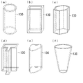
- FIG. 4 is a structural schematic diagram near the liquid surface of another example of the heat exchanger having the deposit suppression structure of the present invention. It is an example of the shape of the cylindrical member of the deposit suppression structure of the heat exchanger of the present invention.
- FIG. 4 is a schematic diagram of an example of a seal member arranged on a cylindrical member of the deposit suppression structure for a heat exchanger of the present invention
- FIG. 4 is a schematic diagram of another example of a heat exchanger having a deposit suppression structure for a heat exchanger of the present invention
- FIG. 4 is a schematic diagram of another example of a heat exchanger having a deposit suppression structure for a heat exchanger of the present invention
- FIG. 1 is a schematic diagram of an example of a heat exchanger having a deposit suppression structure for a heat exchanger of the present invention.
- the heat exchanger 100 arranged in the liquid tank A includes a heat transfer tube 110 and a connector 120 connected to a heat source pipe (not shown).
- a cylindrical member 130 is provided.
- the heat exchanger 100 which is generally called the immersion type, is used with almost the entire heat transfer tube immersed in the liquid in the liquid tank A.
- the heat transfer tube 110 is composed of one or a plurality of tubes, and is arranged to have a loop shape of a size convenient for charging into the liquid tank A. As shown in FIG. An end portion of the heat transfer tube 110 is arranged at a position higher than the liquid surface B. The end of the heat transfer tube 110 located above the liquid surface is connected to a heat source (e.g., steam supply port not shown) piping, from which a heat medium (or refrigerant) is supplied inside the heat transfer tube 110.
- a heat source e.g., steam supply port not shown
- a cylindrical member 130 used as the deposit suppression structure of the present invention is arranged.
- the acid solution in the liquid tank is controlled by immersing the object to be cleaned in the acid liquid tank, adjusting the temperature, and stirring the liquid in the tank.
- the liquid level rises and falls within a certain range and oscillates.
- objects to be cleaned such as steel plates and steel wires are continuously conveyed into the acid bath at high speed, splashes are generated on the surface of the acid solution.
- the acid liquid adheres to the surface of the heat transfer tube above the liquid surface, and the volatile matter evaporates to precipitate the solid content on the surface of the heat transfer tube.
- the tubular member 130 can suppress the fluctuation of the liquid surface inside the tubular member, and can prevent droplets generated on the liquid surface from adhering to the heat transfer tubes. Furthermore, when the sealing member is arranged at the upper end portion of the cylindrical member, an effect of suppressing the evaporation of the volatile matter of the acid liquid inside the cylindrical member can be expected. In this way, the tubular member 130 prevents or suppresses the formation of deposits on the outer surface of the heat transfer tube 110 inside the tubular member. Even in such a case, the surface of the cylindrical member 130 has a simple shape, so it is very easy to remove the deposits.
- FIG. 2 is a schematic diagram of the structure near the liquid surface of an example of a conventional heat exchanger
- Fig. 3 is a conceptual diagram of deposit formation in a conventional heat exchanger
- FIG. 4 is a structural schematic diagram of the vicinity of the liquid surface of an example of the heat exchanger provided with the deposit suppressing structure of the present invention.
- FIG. 4 shows an example in which a sealing member 131 is arranged at the lower end of the cylindrical member 130.
- FIG. 5 is a conceptual diagram of deposit formation in an example of a heat exchanger equipped with the deposit suppression structure of the present invention.
- the heat transfer tubes 110 are exposed to the liquid with their outer surfaces exposed to the liquid, or the surfaces of the heat transfer tubes 110 individually coated.
- the regions C1 where deposits are generated near the liquid surface of the heat exchanger are on the outer surface of each of the heat transfer tubes 110, and the operation to remove the deposits is performed on each heat transfer tube. need to do it. Furthermore, if the deposits on the surface of the heat transfer tube 110 are not removed frequently, the deposits on the surface of the heat transfer tube 110 will unite with each other, and the deposits will become a lump involving the heat transfer tubes. There were many problems such as the difficulty of On the other hand, in the example of the heat exchanger provided with the deposit suppression structure of the present invention shown in FIG. As shown in FIG. 5, the area C2 where deposits are generated near the liquid surface is located on the outer surface of the cylindrical member 130, and even if deposits are formed, they can be easily removed. There is no fear of damaging the heat pipe.
- the tubular member is preferably arranged at a position where the first end of the tubular member is above the liquid surface and the second end is below the liquid surface.
- the lower part of the liquid level means a position lower than the fluctuation range of the liquid level, and the second end of the cylindrical member is always immersed in the liquid in the liquid tank even when the liquid level fluctuates.
- the upper portion of the liquid surface is a position higher than the fluctuation range of the liquid surface, preferably a position where the heat transfer tubes can be covered up to a position where droplets generated on the liquid surface do not reach.
- the tubular member is connected to the support plate or the top plate. , or more preferably through them.
- the cylindrical member arranged in such a manner can block the droplets generated on the liquid surface from the heat transfer tubes.
- FIG. 6 is a structural schematic diagram near the liquid surface of another example of a heat exchanger equipped with the deposit suppression structure of the present invention.
- the cylindrical member may be one in which all the heat transfer tubes of the heat exchanger are collectively inserted as shown in FIG. It may be inserted, or may be extrapolated to a part of the heat transfer tubes as shown in FIG. 6(b).
- the arrangement of the tubular member can be appropriately determined according to the arrangement of the heat exchanger, the occurrence of splashes on the liquid surface, the maintenance situation, and the like.
- the cross-sectional shape of the cylindrical member 130 is not limited as long as it has an inner surface and an outer surface and has a first end and a second end.
- the cross-sectional shape is not limited to a circular shape as shown in FIG.
- An example of (c) may be a hexagon).
- the cross-sectional shape may be irregular as shown in FIG.
- the shape of the tubular member can be appropriately determined according to the arrangement of the heat exchangers, maintenance, and the like.
- the cross-sectional shape and cross-sectional area of the first end and the second end need not be the same.
- the cross-sectional area of the second end below the liquid level may be smaller. In the case of the shape shown in FIG.
- the walls of the tubular member are inclined, so that droplets adhering to the surface of the tubular member can easily drop, and even if the adherents grow, they will grow. There is an advantage that the adhered matter easily falls off by its own weight.
- the cylindrical member may have any shape as described above after being placed in the heat exchanger, and the shape before being placed in the heat exchanger is not limited.
- the tubular member may be formed by rounding a sheet of plate into a cylindrical shape so as to cover the heat transfer tube when it is attached to the heat exchanger.
- the tubular member may be formed by pasting a plurality of plate materials around the heat transfer tube so as to form a tubular shape.
- the wall portion of the cylindrical member has no gaps if possible. As long as it is a material, the wall of the cylindrical member may be mesh-like or have slits or the like. In this case, it is preferable that the outer surface of the tubular member is a surface on which deposits are less likely to form and from which the generated deposits can be easily removed.
- At least the outer surface of the tubular member is preferably smooth and has a contact angle of 90° or more.
- it is possible to adjust the state of the outer surface by polishing the outer surface of the tubular member to adjust the surface shape, or by providing a film made of a material with a large contact angle on the outer surface of the tubular member. is.
- the outer surface of the cylindrical member have a contact angle of 90° or more, deposits are less likely to form on the outer surface of the cylindrical member, and the generated deposits can be easily removed. become a thing.
- the outer surface of the coating layer is preferably smooth and has a contact angle of 90° or more.
- the tubular member is preferably constructed with one or more coating layers on its outer surface.
- the coating layers have a structure that can be peeled off one by one.
- the structure having the coating layer on the surface of the tubular member is used when the surface of the tubular member becomes dirty or when it becomes difficult to remove deposits on the surface of the tubular member due to repeated removal of deposits. A high effect can be obtained again by peeling off the coating layer to form a new surface.
- the coating layer of the tubular member may have a structure in which a film-shaped material is wound around the outer surface of the tubular member and fixed in a tubular shape. In that case, it is possible to release the cylindrical fixation of the coating layer and peel and remove the film.
- the coating layer may be one in which at least a part of the layer is imparted with easy tearability.
- the easy-to-tear property of the coating layer is obtained by providing cuts or scratches on the surface of the coating layer to make it easier to tear along the cuts, by thinning the thickness of a part of the coating layer to provide an easy-to-tear portion, and by using a plurality of resins.
- the material forming at least the outer surface of the tubular member is not easily destroyed by the liquid in the liquid tank and the ambient temperature of the tubular member.
- the material is preferably metal, resin, or the like, which does not break even when some stress or impact is applied.
- the material of the cylindrical member may be metal such as gold, platinum, tantalum, Hastelloy, nickel alloy, etc., which is excellent in corrosion resistance, or resin. good. If it is made of resin, for example, polypropylene (PP), GF-reinforced PP, polyvinyl chloride (PVC), fluororesin, fiber-reinforced plastic (FRP), or the like can be used.
- polytetrafluoroethylene PTFE
- tetrafluoroethylene-perfluoroalkyl vinyl ether copolymer PFA
- FEP tetrafluoroethylene-hexafluoropropylene
- PCTFE chlorotrifluoroethylene
- PVDF polyvinylidene fluoride
- the cylindrical member preferably has a sealing member at least one of the first end and the second end. It is more preferable that the sealing member is arranged at the lower end of the tubular member (lower than the liquid surface), and it is further preferable that the sealing member is arranged at both the upper end and the lower end of the tubular member. .
- the sealing member has a structure in which the heat transfer tube is inserted and prevents liquid from flowing into the cylindrical member. Further, it is more preferable that the sealing member has a structure that inhibits ventilation into the cylindrical member, and more preferably a structure that can block the cylindrical member.
- FIG. 8 is a schematic diagram of an example of a seal plate 800 used as a seal member arranged on the cylindrical member of the deposit suppression structure of the heat exchanger of the present invention.
- the seal plate 800 is provided with through holes 810 through which the heat transfer tubes are inserted.
- the material of the seal plate is preferably one that is not easily destroyed by the liquid in the liquid tank and the ambient temperature of the cylindrical member.
- the material is not particularly limited as long as it does not break even when some stress or impact is applied, such as metal or resin.
- metals such as gold, platinum, tantalum, hastelloy, nickel alloy, etc., which are excellent in corrosion resistance, may be used, or polypropylene (PP), GF-reinforced PP, polychlorinated Vinyl (PVC), fiber reinforced plastic (FRP), fluororesin, fluororubber, perfluoroelastomer, silicone rubber, etc.
- the hole diameter of the through hole 810 is preferably set to be the same as or slightly larger than the outer diameter of the heat transfer tube.
- a filler that reduces the gap between the through hole 810 and the heat transfer tube can be placed in the through hole 810 of the seal plate 800 .
- a filler such as an O-ring may be placed in the through hole 810 of the seal plate 800 to fill the gap between the through hole 810 and the heat transfer tube.
- the seal plate is made of a flexible material such as fluororubber, and the hole diameter of the through hole 810 is the same as or slightly smaller than the outer diameter of the heat transfer tube. It is also possible to adopt a structure in which the tubular member is closed when the is inserted. Alternatively, for example, a structure in which two seal plates are prepared and a sheet made of an elastic material such as rubber is sandwiched and fixed between the seal plates may be employed. In this case, the sheet made of elastic material should have a hole with a diameter equal to or slightly smaller than the outer diameter of the heat transfer tube at a position corresponding to the through hole of the seal plate.
- the two seal plates can also be configured to be fixed using fixing holes 820 . A sheet made of an elastic material placed between the two seal plates can fill the gap between the through-hole 810 and the heat transfer tube, closing the tubular member.
- the sealing member may be prepared by molding into a shape as shown in the example of FIG. 8 before inserting the heat transfer tube, inserting the heat transfer tube into the through hole 810 and fixing it to the cylindrical member. Alternatively, it may be formed by filling the space between the tubular member and the heat transfer tube with the material of the sealing member so that the shape shown in the example of FIG. 8 is obtained after the heat transfer tube and the tubular member are arranged. .
- the tubular member or the sealing member is one whose structure can be divided. As a result, the tubular member can be removed without removing heat exchanger components such as heat transfer tubes and connectors from the state of being attached to the heat exchanger, and only the tubular member can be replaced.
- a cylindrical member provided with a sealing member supplies gas or liquid from a gap between the sealing member and the heat transfer tube, etc., and creates a differential pressure between the inside and outside of the cylindrical member to create a slight positive pressure inside the cylindrical member. can.
- the liquid supplied to the inside of the cylindrical member may be water or the like, but it is more preferable to use the same kind of liquid as the liquid in the liquid phase in terms of concentration control. Further, when the liquid supplied to the inside of the shaped member is an acid liquid, a self-cleaning effect against scale adhesion can be expected.
- the heat exchanger 100 includes a connector 120 that connects the heat transfer tubes 110 and the heat source piping, a tubular member 130, a spacer 140 that holds the arrangement of the heat transfer tubes 110 in the liquid tank A, and spacers that are connected to form a shape.
- a fixing member 150 that maintains the heat transfer tube 110, a rod 160 that prevents the heat transfer tube 110 from floating, and the like may be provided (see FIG. 1).
- FIG. 9 is a schematic diagram of another example of a heat exchanger provided with the deposit suppression structure for a heat exchanger of the present invention.
- a plurality of heat transfer tubes 110 fixed in a loop shape are arranged in parallel, and the end of each heat transfer tube 110 is connected to a connector (not shown) connected to a heat source pipe.
- the heat transfer tubes are gathered in one place on each of the inlet side and the outlet side of the heat medium, and a cylindrical member 130 is provided so as to cover the part corresponding to the liquid surface of the gathered heat transfer tubes 110. are placed.
- the upper end of the cylindrical member (above the liquid surface) is connected to a top plate 160 that functions as a lid for the liquid tank. It has a structure that is blocked from the generated droplets.
- FIG. 10 is a schematic diagram of another example of a heat exchanger provided with the deposit suppression structure for a heat exchanger of the present invention.
- a plurality of heat transfer tubes 110 are bundled and arranged in a U shape, and the ends of the heat transfer tubes 110 are connected to connectors 120 connected to heat source piping.
- the bundle of heat transfer tubes is arranged such that the inlet side end and the outlet side end of the heat medium are adjacent to each other, and the portion corresponding to the vicinity of the liquid surface of the heat transfer tubes 110 is collectively fitted around the cylindrical member 130.
- the heat exchanger may be one in which the heat transfer tubes 110 are arranged in a loop shape, or as in the example of FIG. It may be arranged in a U shape.
- At least the outer surface of the heat transfer tube is made of at least one material selected from fluororesins. Any material may be used as long as it is not easily destroyed by the liquid in the liquid bath and the ambient temperature of the cylindrical member. Although the material may be metal, it is more preferable to use a resin whose shape can be freely changed according to the shape of the liquid tank. If it is made of resin, for example, polypropylene (PP), GF-reinforced PP, polyvinyl chloride (PVC), fluororesin, fiber-reinforced plastic (FRP), or the like can be used.
- PP polypropylene
- GF-reinforced PP polyvinyl chloride
- FRP fiber-reinforced plastic
- polytetrafluoroethylene PTFE
- tetrafluoroethylene-perfluoroalkyl vinyl ether copolymer PFA
- FEP tetrafluoroethylene-hexafluoropropylene
- PCTFE chlorotrifluoroethylene
- PVDF polyvinylidene fluoride
- the fluororesin may contain a filler in order to impart or improve thermal conductivity, electrical conductivity, barrier properties, mechanical strength, or the like.
- fillers contained in the fluororesin include amorphous carbon particles, graphite particles, and glass fibers.
- the present invention it is possible to effectively prevent or suppress the formation of deposits on the surface of heat transfer tubes of a heat exchanger, and there is a risk of harm to respiratory organs and contact with acid liquid.
- the frequency of severe maintenance work for removing scale pieces deposited on the heat transfer tubes can be greatly reduced.
- the removal of deposits is easy and the work of removing deposits does not damage the heat transfer tubes, so the heat exchanger can be used while maintaining high performance.
- a liquid tank, B liquid surface, C area where deposits are generated 100 heat exchanger, 110 heat transfer tube, 120 connector, 130 tubular member, 131 sealing member, 140 spacer, 150 fixing member, 160 rod seal plate 800, penetration hole 810, fixing hole 820
Landscapes
- Engineering & Computer Science (AREA)
- Physics & Mathematics (AREA)
- Thermal Sciences (AREA)
- Mechanical Engineering (AREA)
- General Engineering & Computer Science (AREA)
- Heat-Exchange Devices With Radiators And Conduit Assemblies (AREA)
Abstract
The purpose of the present invention is to provide a deposit suppression structure for a heat exchanger to be used in a state of being immersed in a liquid, and a heat exchanger having the deposit suppression structure. The present invention addresses the problem by providing: a deposit suppression structure for a heat exchanger that is characterized by comprising a cylindrical member fitted on the outside of, among a plurality of heat transfer pipes, at least one of the heat transfer pipes, and that is characterized in that the cylindrical member has inner and outer surfaces and first and second ends, and the cylindrical member is provided with a seal member at the first end and/or the second end; and a heat exchanger having the deposit suppression structure.
Description
本発明は、熱交換器の付着物抑制構造、及び付着物抑制構造を有する熱交換器に関する。特に、本発明は、液槽内に浸漬して使用される熱交換器において、液面近傍の伝熱管表面への付着物の堆積を抑制する構造と、その構造を備えた熱交換器に関する。
TECHNICAL FIELD The present invention relates to a deposit suppression structure for a heat exchanger and a heat exchanger having the deposit suppression structure. More particularly, the present invention relates to a heat exchanger that is used by being immersed in a liquid tank, and relates to a structure that suppresses deposition of deposits on the surfaces of heat transfer tubes near the liquid surface, and a heat exchanger that has such a structure.
化学洗浄、メッキ液温度制御、薬液温度制御、温泉熱利用などの用途に使用される熱交換器として、耐食性に優れた伝熱管で構成された投げ込み式熱交換器が用いられている。投げ込み式熱交換器は、1本または複数本の伝熱管で構成された熱交換器を液槽内で伝熱管のほぼ全体を液体中に浸漬し、伝熱管の一部、つまり熱媒または冷媒配管との接続部分を液体の外(液面より上部)に配置して使用するものである。
Immersion-type heat exchangers made up of heat transfer tubes with excellent corrosion resistance are used as heat exchangers used for chemical cleaning, plating liquid temperature control, chemical liquid temperature control, hot spring heat utilization, etc. Immersion type heat exchanger is a heat exchanger consisting of one or more heat transfer tubes in a liquid bath, almost the entire heat transfer tube is immersed in liquid, and a part of the heat transfer tube, that is, the heat medium or refrigerant It is used by arranging the connection part with the pipe outside the liquid (above the liquid surface).
化学洗浄とは脱脂、脱錆、防錆などの目的に合わせて、酸、アルカリ、溶剤などを使用して洗浄対象物の表面の不要物や汚れを化学的に除去する方法であり、薬品を貯めた液槽内に、洗浄対象物を浸漬する方式で行われることが多い。このとき、液槽内の薬品を加温または冷却することを目的に熱交換器が使用される。化学洗浄の中でも酸洗は、鋼板や線材、形鋼やパイプ、ステンレス材またはチタン板などの金属製品を扱う分野で用いられ、圧延や熱処理、溶接などによって生じた酸化皮膜などの金属製品表面の不純物を除去するために行われる洗浄作業である。洗浄には、塩酸、硫酸、硝酸やフッ酸などの酸液が用いられる。例えば、板材や線材などを連続的に処理する場合、酸液を満たした液槽内に板材や線材を連続的に搬送し、洗浄を行う。このとき、酸液は60~110℃程度に加温して用いられることが多く、液槽内には1基または複数基の熱交換器が配置される。液槽内の酸液には、鋼材の表面から脱離した酸化物(スケール片)や油汚れなどが混在している。特に油分が混入したスケール片が熱交換器の表面に付着すると、スケール片の凝集体となり、熱交換器の表面に堆積していく。熱交換器へのスケール片の付着・堆積は、熱交換器の熱交換効率低下を招くだけでなく、そのスケール片の重量により熱交換器が押しつぶされ、熱交換器の破損の原因ともなっていた。さらに、この熱交換器に付着堆積したスケール片を除去する作業は、酸液に接触する危険性があり、酸液による呼吸器官への害もあるため、安全面で問題があった。このような問題を解決するために、特許文献1には、スケール片が堆積・成長しやすい熱交換器のコーナ部に圧縮空気または槽内酸液を吹き付けて、コーナー部に付着したスケール片等を洗い流すことで、スケール片や油などの凝集堆積(以降、スケールと言う)から熱交換器を保護し、熱交換効率低下や変形を防止する発明が開示されている。
Chemical cleaning is a method of chemically removing unnecessary substances and dirt from the surface of the object to be cleaned using acids, alkalis, solvents, etc., according to the purpose of degreasing, derusting, and rust prevention. It is often carried out by immersing the object to be cleaned in a pool of liquid. At this time, a heat exchanger is used for the purpose of heating or cooling the chemicals in the liquid bath. Among chemical cleaning methods, pickling is used in fields that handle metal products such as steel plates, wire rods, shaped steels, pipes, stainless steel materials, and titanium plates. It is a cleaning operation performed to remove impurities. Acid solutions such as hydrochloric acid, sulfuric acid, nitric acid, and hydrofluoric acid are used for cleaning. For example, in the case of continuously treating plate materials and wire rods, the plate materials and wire rods are continuously transported into a liquid tank filled with an acid solution and washed. At this time, the acid solution is often used after being heated to about 60 to 110° C., and one or more heat exchangers are arranged in the solution tank. The acid solution in the liquid tank contains oxides (scale fragments) detached from the surface of the steel material, oil stains, and the like. In particular, when scale pieces mixed with oil adhere to the surface of the heat exchanger, they become agglomerates of the scale pieces and accumulate on the surface of the heat exchanger. The adhesion and accumulation of scale pieces on the heat exchanger not only reduces the heat exchange efficiency of the heat exchanger, but also causes the heat exchanger to be crushed by the weight of the scale pieces, causing damage to the heat exchanger. . Furthermore, the work of removing the scale pieces deposited on the heat exchanger poses a safety problem because there is a risk of coming into contact with the acid solution, and the acid solution also harms the respiratory organs. In order to solve such a problem, Patent Document 1 discloses that compressed air or an acid solution in a tank is blown to the corners of a heat exchanger where scale pieces tend to accumulate and grow to remove scale pieces adhering to the corners. is washed away to protect the heat exchanger from agglomeration and deposition of scale pieces, oil, etc. (hereinafter referred to as scale), thereby preventing deterioration in heat exchange efficiency and deformation.
また、酸洗の酸液槽内で使用される投げ込み式の熱交換器においては、液面付近の伝熱管表面にスケールが付着することが問題となっていた。特許文献1に記載された技術では、液槽内の液体に完全に浸漬された部分の熱交換器へのスケール片の付着防止には有効であるが、液面の上部を含む液面近傍においては、その効果を発揮することが困難であった。この伝熱管表面と液面とが接触する付近では、例えば鋼板などを酸液槽内に浸漬したときなどに、液面の高さが上下に変動することにより伝熱管表面にスケールが付着することが問題となっている。このスケールは、伝熱管表面に付着した酸液の揮発分が蒸発して固形分が残り、その固形分に酸液が繰り返し付着して再び揮発分が蒸発し、大きな固形分の固まりとなることで形成される。このようなスケールは、堅牢化しつつ、より大きな塊となって、伝熱管が破損する原因となり、また、除去することが困難となる。
In addition, in the immersion type heat exchanger used in the acid bath for pickling, there was a problem of scale adhering to the surface of the heat transfer tubes near the liquid surface. The technique described in Patent Document 1 is effective in preventing scale pieces from adhering to the heat exchanger in the portion completely immersed in the liquid in the liquid tank, but in the vicinity of the liquid surface including the upper part of the liquid surface However, it was difficult to exert its effect. In the vicinity of the contact between the heat transfer tube surface and the liquid surface, for example, when a steel plate or the like is immersed in an acid liquid bath, the liquid surface fluctuates up and down, causing scale to adhere to the heat transfer tube surface. is the problem. This scale is formed by evaporating the volatile matter of the acid solution adhering to the surface of the heat transfer tube, leaving a solid content, and repeatedly adhering the acid solution to the solid content, evaporating the volatile matter again, and becoming a large mass of solid content. formed by While such scales are hardened, they become larger lumps, causing breakage of the heat transfer tubes, and are difficult to remove.
このような問題に対し、特許文献2には、液面と接触する付近の伝熱管の外周面に生成するスケールの付着を防止する方法として、鋼板などを洗浄する酸液などの溶液中で使用される熱交換器の伝熱管をフッ素樹脂製の熱収縮チューブで被覆する方法が記載されている。具体的には、収縮させた熱収縮チューブが伝熱管のスケールが付着する範囲を覆うように、熱収縮チューブの位置決めを行い、この位置で熱収縮チューブを加熱して、伝熱管を被覆する保護チューブを形成する方法である。この方法を用いると、スケールが伝熱管には直接付着せず、保護チューブに付着するため、伝熱管の損傷を防止することができる、とされている。
In response to such problems, Patent Document 2 describes a method for preventing scale from adhering to the outer peripheral surface of a heat transfer tube in the vicinity of the contact with the liquid surface. A method of covering the heat transfer tubes of a heat exchanger with a fluororesin heat-shrinkable tube is described. Specifically, the heat-shrinkable tube is positioned so that it covers the area where scales adhere to the heat-conducting tube, and the heat-shrinkable tube is heated at this position to cover the heat-conducting tube. A method of forming a tube. It is said that by using this method, the scale does not adhere directly to the heat transfer tubes but adheres to the protection tubes, thereby preventing damage to the heat transfer tubes.
しかし、引用文献2の技術では、スケールが伝熱管に直接付着することはないが、伝熱管を覆う保護チューブにはスケールが付着することになる。そのため、頻繁に付着物を除去しなければ大きな塊となり、さらに伝熱管と伝熱管の間の付着物同士が伝熱管を巻き込んで一体化すると、付着物の除去はさらに困難になるという問題があった。一体化して大きな塊となった付着物は、その部分の熱伝導を低下させるだけではなく、付着物を除去する際に伝熱管を破損したり、付着物によって伝熱管が折られる、などの重大な問題を引き起こしていた。
However, with the technique of Cited Document 2, scale does not adhere directly to the heat transfer tubes, but scale adheres to the protective tubes that cover the heat transfer tubes. Therefore, if the deposits are not removed frequently, they become large lumps, and if the deposits between the heat transfer tubes entangle the heat transfer tubes and become integrated, there is a problem that the removal of the deposits becomes even more difficult. rice field. Adhesives that coalesce into a large mass not only reduce the heat conduction of that part, but also cause damage to the heat transfer tubes when removing the adherings, or break the heat transfer tubes due to the adherings. was causing problems.
本発明は、こうした従来技術の問題点を解決するために成されたものであり、熱交換器の付着物抑制構造と、その付着物抑制構造を有する熱交換器を提供することを目的とする。
SUMMARY OF THE INVENTION The present invention has been made to solve the problems of the prior art, and it is an object of the present invention to provide a deposit suppression structure for a heat exchanger and a heat exchanger having the deposit suppression structure. .
上記の課題を鑑み検討した結果、本発明に至った。具体的には、本発明に係る熱交換器の付着物抑制構造は、1本または複数本の伝熱管を備える熱交換器において、前記熱交換器は、前記伝熱管の外部表面に液体が接触して熱交換を行う熱交換器であって、前記熱交換器は前記伝熱管のうち1本または複数本の伝熱管に外挿される筒状部材を備え、前記筒状部材は内部表面及び外部表面を有しかつ第1端及び第2端を有し、前記筒状部材は前記第1端及び前記第2端の少なくともいずれか一方にシール部材を備えることを特徴とする。
As a result of considering the above problems, the present invention was reached. Specifically, the deposit suppression structure for a heat exchanger according to the present invention is a heat exchanger comprising one or a plurality of heat transfer tubes, wherein the heat exchanger is configured such that the outer surfaces of the heat transfer tubes are brought into contact with a liquid. The heat exchanger includes a tubular member that is fitted over one or more of the heat transfer tubes, the tubular member having an inner surface and an outer surface. The tubular member has a surface and has a first end and a second end, wherein the tubular member is provided with a sealing member at least one of the first end and the second end.
また、上記課題は、前記筒状部材が前記第1端及び前記第2端の両方にシール部材を備えることにより、より好ましく解決される。
Further, the above problem is more preferably solved by providing sealing members at both the first end and the second end of the cylindrical member.
また、前記筒状部材は、少なくとも外部表面において接触角が90°以上であることが好ましい。
Further, it is preferable that the tubular member has a contact angle of 90° or more at least on the outer surface.
前記筒状部材は、その外部表面上に1つまたは複数の被覆層を備えた構造であることが、好ましい。また、その被覆層は、少なくとも一部に易引き裂き性を付与した層であることが、より好ましい。また、前記被覆層は、少なくとも外部表面において接触角が90°以上であることが好ましい。
The tubular member preferably has a structure with one or more coating layers on its outer surface. Moreover, it is more preferable that the coating layer is a layer at least partially provided with easy tearability. Moreover, the coating layer preferably has a contact angle of 90° or more at least on the outer surface.
また、上記課題を解決するため、本発明の付着物抑制構造を有する熱交換器は、1本または複数本の伝熱管を備える熱交換器において、前記熱交換器は液槽内に配置され前記伝熱管の外部表面に液体が接触して熱交換を行う熱交換器であって、前記熱交換器は前記伝熱管のうち1本または複数本の伝熱管に外挿される筒状部材を備え、前記筒状部材は内部表面及び外部表面を有しかつ第1端及び第2端を有し、前記筒状部材は前記第1端及び前記第2端の少なくともいずれか一方にシール部材を備え、前記筒状部材の一方の端部が液槽の液面より上部に位置するように設置されることを特徴とする。
Further, in order to solve the above problems, the heat exchanger having the deposit suppression structure of the present invention is a heat exchanger including one or more heat transfer tubes, wherein the heat exchanger is arranged in a liquid tank and the A heat exchanger that exchanges heat by contacting a liquid with the outer surface of a heat transfer tube, wherein the heat exchanger includes a tubular member that is fitted around one or more of the heat transfer tubes, said tubular member having an inner surface and an outer surface and having a first end and a second end, said tubular member having a seal member at least one of said first end and said second end; One end of the cylindrical member is installed so as to be positioned above the liquid surface of the liquid tank.
また、本発明の付着物抑制構造を有する熱交換器の伝熱管は、少なくとも外部表面の材質がフッ素樹脂の中から選択される少なくとも1種の樹脂で構成されることが好ましい。
In addition, it is preferable that at least the outer surface of the heat transfer tube of the heat exchanger having the deposit suppression structure of the present invention is made of at least one resin selected from fluororesins.
本発明によれば、熱交換器の伝熱管表面への付着物の生成自体を、効果的に防止または抑制することが可能である。熱交換器への付着物を除去する保守作業の頻度を大幅に減らすことができ、また、付着物の除去が容易で、伝熱管の損傷を抑えることができる。
According to the present invention, it is possible to effectively prevent or suppress the formation of deposits on the surface of heat transfer tubes of a heat exchanger. The frequency of maintenance work for removing deposits on the heat exchanger can be greatly reduced, and the removal of deposits is easy, so damage to the heat transfer tubes can be suppressed.
本発明による熱交換器の付着物抑制構造、及び付着物抑制構造を有する熱交換器の好適な実施形態について、図を用いて説明する。各図において、同一の要素には同一の符号を付し、同様の説明となる場合には、重複する説明は省略する場合がある。
A preferred embodiment of a deposit suppression structure for a heat exchanger and a heat exchanger having the deposit suppression structure according to the present invention will be described with reference to the drawings. In each figure, the same elements are denoted by the same reference numerals, and redundant descriptions may be omitted when similar descriptions are given.
図1は、本発明の熱交換器の付着物抑制構造を有する熱交換器の一例の概略図である。図1に示すように、液槽A内に配置された熱交換器100は、伝熱管110、熱源配管(図示せず)と接続されるコネクタ120とを備え、さらに本発明の付着物抑制構造を構成する筒状部材130を備える。
FIG. 1 is a schematic diagram of an example of a heat exchanger having a deposit suppression structure for a heat exchanger of the present invention. As shown in FIG. 1, the heat exchanger 100 arranged in the liquid tank A includes a heat transfer tube 110 and a connector 120 connected to a heat source pipe (not shown). A cylindrical member 130 is provided.
一般的に投げ込み式タイプとも呼ばれる熱交換器100は、伝熱管のほぼ全体を液槽A内の液体に浸漬されて使用される。伝熱管110は、1本または複数本で構成され、液槽A内へ装入するのに都合のよい大きさのループ形状を有するように配置される。伝熱管110の端部は液面Bより高くなる位置に配置される。液面より上部に配置された伝熱管110の端末は、熱源(例えば、図示していない水蒸気供給口)配管に接続され、そこから伝熱管110内部に熱媒(または冷媒)が供給される。
The heat exchanger 100, which is generally called the immersion type, is used with almost the entire heat transfer tube immersed in the liquid in the liquid tank A. The heat transfer tube 110 is composed of one or a plurality of tubes, and is arranged to have a loop shape of a size convenient for charging into the liquid tank A. As shown in FIG. An end portion of the heat transfer tube 110 is arranged at a position higher than the liquid surface B. The end of the heat transfer tube 110 located above the liquid surface is connected to a heat source (e.g., steam supply port not shown) piping, from which a heat medium (or refrigerant) is supplied inside the heat transfer tube 110.
伝熱管110の液面B近傍には、本発明の付着物抑制構造として用いられる筒状部材130が配置される。例えば、鋼板や鋼線材などの酸洗工程では、酸液槽内に洗浄対象物を浸漬する操作、温調操作や液槽内の液体の攪拌操作などの操作により、液槽内の酸液の液面が一定範囲で上下し、揺動する。また、酸液槽内に、鋼板や鋼線材などの洗浄対象物を連続的に高速で搬送するときなどには、酸液の液面上において飛沫が発生する。このとき、液面より上部にある伝熱管表面に酸液が付着し、その揮発分が蒸発して伝熱管表面で固形分が析出する。これを繰り返すと付着物は成長し大きくなる。筒状部材130は、筒状部材内部における液面の揺動を抑制し、また、液面上で発生した飛沫が伝熱管へ付着することを防止できる。さらに、筒状部材の上側端部にシール部材を配置した場合には、筒状部材内部の酸液の揮発分の蒸発を抑える効果も期待できる。このように、筒状部材130は、筒状部材内部の伝熱管110の外部表面への付着物の生成を防止または抑制するものであり、また、筒状部材130の外部表面に付着物が生成した場合であっても、筒状部材130の表面は単純な形状であるために、付着物の除去が非常に容易である。
In the vicinity of the liquid surface B of the heat transfer tube 110, a cylindrical member 130 used as the deposit suppression structure of the present invention is arranged. For example, in the pickling process for steel plates and steel wire rods, the acid solution in the liquid tank is controlled by immersing the object to be cleaned in the acid liquid tank, adjusting the temperature, and stirring the liquid in the tank. The liquid level rises and falls within a certain range and oscillates. Further, when objects to be cleaned such as steel plates and steel wires are continuously conveyed into the acid bath at high speed, splashes are generated on the surface of the acid solution. At this time, the acid liquid adheres to the surface of the heat transfer tube above the liquid surface, and the volatile matter evaporates to precipitate the solid content on the surface of the heat transfer tube. If this is repeated, the deposit will grow and become larger. The tubular member 130 can suppress the fluctuation of the liquid surface inside the tubular member, and can prevent droplets generated on the liquid surface from adhering to the heat transfer tubes. Furthermore, when the sealing member is arranged at the upper end portion of the cylindrical member, an effect of suppressing the evaporation of the volatile matter of the acid liquid inside the cylindrical member can be expected. In this way, the tubular member 130 prevents or suppresses the formation of deposits on the outer surface of the heat transfer tube 110 inside the tubular member. Even in such a case, the surface of the cylindrical member 130 has a simple shape, so it is very easy to remove the deposits.
図2は、従来の熱交換器の一例の液面近傍の構造概略図であり、図3は従来の熱交換器の付着物生成の概念図である。図4は本発明の付着物抑制構造を備えた熱交換器の一例の液面近傍の構造概略図である。図4は、筒状部材130の下端部にシール部材131を配置した例を示している。また、図5は、本発明の付着物抑制構造を備えた熱交換器の一例の付着物生成の概念図である。図2の従来の熱交換器では、伝熱管110は、外部表面が液中に露出した状態、もしくは伝熱管110の表面が個別に被覆された状態で液中に曝されている。図3に示すように、熱交換器の液面近傍で付着物が生成する領域C1は伝熱管110のそれぞれの外部表面上にあり、生成した付着物を取り除く作業は伝熱管1本1本に対して行う必要がある。さらに、伝熱管110の表面の付着物を頻繁に除去しなければ、伝熱管110の表面の付着物同士が一体化し、付着物が伝熱管を巻き込んだ塊となるため、付着物を除去することが困難になるなど問題が多かった。これに対し、図4の本発明の付着物抑制構造を備えた熱交換器の例では、伝熱管110の束を取り囲むように筒状部材130が配置されている。図5に示すように、液面近傍で付着物が生成する領域C2は筒状部材130の外部表面にあり、付着物が生成した場合でも取り除くのが容易であり、付着物の除去作業により伝熱管を損傷する虞もない。
Fig. 2 is a schematic diagram of the structure near the liquid surface of an example of a conventional heat exchanger, and Fig. 3 is a conceptual diagram of deposit formation in a conventional heat exchanger. FIG. 4 is a structural schematic diagram of the vicinity of the liquid surface of an example of the heat exchanger provided with the deposit suppressing structure of the present invention. FIG. 4 shows an example in which a sealing member 131 is arranged at the lower end of the cylindrical member 130. As shown in FIG. FIG. 5 is a conceptual diagram of deposit formation in an example of a heat exchanger equipped with the deposit suppression structure of the present invention. In the conventional heat exchanger of FIG. 2, the heat transfer tubes 110 are exposed to the liquid with their outer surfaces exposed to the liquid, or the surfaces of the heat transfer tubes 110 individually coated. As shown in FIG. 3, the regions C1 where deposits are generated near the liquid surface of the heat exchanger are on the outer surface of each of the heat transfer tubes 110, and the operation to remove the deposits is performed on each heat transfer tube. need to do it. Furthermore, if the deposits on the surface of the heat transfer tube 110 are not removed frequently, the deposits on the surface of the heat transfer tube 110 will unite with each other, and the deposits will become a lump involving the heat transfer tubes. There were many problems such as the difficulty of On the other hand, in the example of the heat exchanger provided with the deposit suppression structure of the present invention shown in FIG. As shown in FIG. 5, the area C2 where deposits are generated near the liquid surface is located on the outer surface of the cylindrical member 130, and even if deposits are formed, they can be easily removed. There is no fear of damaging the heat pipe.
筒状部材は、筒状部材の第1端が液面の上部にあり、第2端が液面の下部にある位置に配置することが好ましい。ここで、液面の下部とは、液面の変動範囲を超えて低い位置であり、筒状部材の第2端は液面が変動した場合でも常に液槽中の液体に浸漬された状態にあることが好ましい。液面の上部とは、液面の変動範囲を超えて高い位置であり、好ましくは液面上で発生する飛沫が届かない位置まで伝熱管を覆うことができる位置である。液槽内の液面と、伝熱管と熱源配管の接続部との間に、支持板やトッププレートなどが配置された熱交換器においては、筒状部材は、支持板またはトッププレートなどに接続、またはそれらを貫通して固定されていることがより好ましい。そのように配置された筒状部材は、液面上で発生する飛沫を、伝熱管から遮断することができる。
The tubular member is preferably arranged at a position where the first end of the tubular member is above the liquid surface and the second end is below the liquid surface. Here, the lower part of the liquid level means a position lower than the fluctuation range of the liquid level, and the second end of the cylindrical member is always immersed in the liquid in the liquid tank even when the liquid level fluctuates. Preferably. The upper portion of the liquid surface is a position higher than the fluctuation range of the liquid surface, preferably a position where the heat transfer tubes can be covered up to a position where droplets generated on the liquid surface do not reach. In a heat exchanger in which a support plate, top plate, or the like is arranged between the liquid surface in the liquid tank and the connection between the heat transfer tube and the heat source pipe, the tubular member is connected to the support plate or the top plate. , or more preferably through them. The cylindrical member arranged in such a manner can block the droplets generated on the liquid surface from the heat transfer tubes.
図6は、本発明の付着物抑制構造を備えた熱交換器の別の一例の、液面近傍の構造概略図である。筒状部材は、図4のように、熱交換器のすべての伝熱管を一括して外挿されたものであってもよいし、図6(a)のように伝熱管を分割して外挿されたものであってもよく、また、図6(b)のように一部の伝熱管に外挿されたものであってもよい。筒状部材の配置は、熱交換器の配置状況、液面上での飛沫の発生やメンテナンスの状況などに合わせて、適宜決めることができる。
FIG. 6 is a structural schematic diagram near the liquid surface of another example of a heat exchanger equipped with the deposit suppression structure of the present invention. The cylindrical member may be one in which all the heat transfer tubes of the heat exchanger are collectively inserted as shown in FIG. It may be inserted, or may be extrapolated to a part of the heat transfer tubes as shown in FIG. 6(b). The arrangement of the tubular member can be appropriately determined according to the arrangement of the heat exchanger, the occurrence of splashes on the liquid surface, the maintenance situation, and the like.
筒状部材130の形状は、内部表面及び外部表面を有しかつ第1端及び第2端を有するものであれば、断面形状は限定されない。例えば図7(a)に示したような、断面形状が円形のものに限定されず、図7(b)のように断面形状が四角形、または図7(c)のように多角形(図7(c)の例は六角形)であってもよい。また、伝熱管の配置形状に合わせて図7(d)または(e)のように、断面形状が不定形のものであってもよい。筒状部材の形状は、熱交換器の配置状況やメンテナンスの状況などに合わせて、適宜決めることができる。また、第1端と第2端の断面形状や断面積が同じである必要はなく、例えば図7(f)のように、液面の上部にある第1端の断面積の方が大きく、液面の下部にある第2端の断面積の方が小さいものであってもよい。図7(f)のような形状の場合、筒状部材の壁部が傾斜していることで、筒状部材の表面に付着した液滴が落下しやすく、また付着物が成長した場合でも成長した付着物が自重で落下しやすい利点がある。
The cross-sectional shape of the cylindrical member 130 is not limited as long as it has an inner surface and an outer surface and has a first end and a second end. For example, the cross-sectional shape is not limited to a circular shape as shown in FIG. An example of (c) may be a hexagon). Also, the cross-sectional shape may be irregular as shown in FIG. The shape of the tubular member can be appropriately determined according to the arrangement of the heat exchangers, maintenance, and the like. In addition, the cross-sectional shape and cross-sectional area of the first end and the second end need not be the same. For example, as shown in FIG. The cross-sectional area of the second end below the liquid level may be smaller. In the case of the shape shown in FIG. 7(f), the walls of the tubular member are inclined, so that droplets adhering to the surface of the tubular member can easily drop, and even if the adherents grow, they will grow. There is an advantage that the adhered matter easily falls off by its own weight.
筒状部材は、熱交換器に配置した後に上述のような形状になっているものであればよく、熱交換器へ配置する前の形状は限定されない。例えば、筒状部材は、1枚の板材を、熱交換器に取り付けるときに伝熱管の周囲を覆うように円筒形に丸めて固定したものであってもよい。また、例えば、筒状部材は、複数枚の板材を、伝熱管の周囲に筒状になるように貼り合わせたものであってもよい。筒状部材の壁部は、できれば隙間が無いものが好ましいが、筒状部材内部における液面の揺動を抑制し、また、発生した飛沫が伝熱管へ付着することを防止する効果が得られるものであれば、筒状部材の壁部がメッシュ状、スリットなどを有するもので構成されていてもよい。そのとき、筒状部材の外部表面は、付着物が生成しにくく、また生成した付着物が除去し易い表面であることが好ましい。
The cylindrical member may have any shape as described above after being placed in the heat exchanger, and the shape before being placed in the heat exchanger is not limited. For example, the tubular member may be formed by rounding a sheet of plate into a cylindrical shape so as to cover the heat transfer tube when it is attached to the heat exchanger. Further, for example, the tubular member may be formed by pasting a plurality of plate materials around the heat transfer tube so as to form a tubular shape. It is preferable that the wall portion of the cylindrical member has no gaps if possible. As long as it is a material, the wall of the cylindrical member may be mesh-like or have slits or the like. In this case, it is preferable that the outer surface of the tubular member is a surface on which deposits are less likely to form and from which the generated deposits can be easily removed.
筒状部材の少なくとも外部表面は、平滑で、接触角が90°以上であることが好ましい。例えば、筒状部材の外部表面を研磨して表面形状を調整する、筒状部材の外部表面に接触角が大きい材質の被膜を設ける、などの方法により、外部表面の状態を調整することが可能である。筒状部材の外部表面を接触角が90°以上であるものにすることで、筒状部材はその外部表面に付着物が生成しにくく、また、生成した付着物を容易に除去することができるものとなる。後述する、筒状部材の外部表面上に被覆層を備えた構造である場合、被覆層の外部表面は、平滑で接触角が90°以上であることが好ましい。
At least the outer surface of the tubular member is preferably smooth and has a contact angle of 90° or more. For example, it is possible to adjust the state of the outer surface by polishing the outer surface of the tubular member to adjust the surface shape, or by providing a film made of a material with a large contact angle on the outer surface of the tubular member. is. By making the outer surface of the cylindrical member have a contact angle of 90° or more, deposits are less likely to form on the outer surface of the cylindrical member, and the generated deposits can be easily removed. become a thing. In the case of a structure having a coating layer on the outer surface of the cylindrical member, which will be described later, the outer surface of the coating layer is preferably smooth and has a contact angle of 90° or more.
筒状部材は、その外部表面上に1つまたは複数の被覆層を備えた構造であることが好ましい。被覆層を複数備える場合、被覆層は1層ずつ剥離可能な構造であることが好ましい。筒状部材の表面に被覆層を備えた構造は、筒状部材の表面が汚れたり、筒状部材の表面の付着物の除去を繰り返すことによって付着物の除去がし難くなった場合などに、被覆層を剥離して新しい表面とすることで、再び高い効果を得ることができる。また、被覆層を複数備えている構造では、外側の被覆層から1層ずつ、付着物とともに剥離させることが可能で、簡便に繰り返し新しい表面を得ることができる。また、筒状部材の被覆層は、筒状部材の外部表面上にフィルム形状のものを巻き付けて、筒状に固定した構造であってもよい。その場合は、被覆層の筒状の固定を外してフィルムを剥離し除去することが可能である。また、被覆層は、層の少なくとも一部に易引き裂き性を付与したものであってもよい。被覆層の易引き裂き性は、被覆層の表面に切り込みや傷を設けてその切込みに沿って引き裂き易くする、被覆層の一部の肉厚を薄くして裂き易い部分を設ける、複数の樹脂を混合した材料などを用いて作成した易引き裂き性を有するチューブまたはフィルムを被覆層にする、などの方法により、実現できる。易引き裂き性を付与した被覆層を用いた場合、被覆層を剥離する際に特別な道具が不要であり、作業性が高い。
The tubular member is preferably constructed with one or more coating layers on its outer surface. When a plurality of coating layers are provided, it is preferable that the coating layers have a structure that can be peeled off one by one. The structure having the coating layer on the surface of the tubular member is used when the surface of the tubular member becomes dirty or when it becomes difficult to remove deposits on the surface of the tubular member due to repeated removal of deposits. A high effect can be obtained again by peeling off the coating layer to form a new surface. In addition, in a structure having a plurality of coating layers, it is possible to peel off the outer coating layer one by one together with the adhered matter, so that a new surface can be easily obtained repeatedly. Also, the coating layer of the tubular member may have a structure in which a film-shaped material is wound around the outer surface of the tubular member and fixed in a tubular shape. In that case, it is possible to release the cylindrical fixation of the coating layer and peel and remove the film. Moreover, the coating layer may be one in which at least a part of the layer is imparted with easy tearability. The easy-to-tear property of the coating layer is obtained by providing cuts or scratches on the surface of the coating layer to make it easier to tear along the cuts, by thinning the thickness of a part of the coating layer to provide an easy-to-tear portion, and by using a plurality of resins. It can be realized by a method such as using an easily tearable tube or film made of a mixed material or the like as the coating layer. When a coating layer imparted with easy tearability is used, a special tool is not required when peeling the coating layer, and workability is high.
筒状部材の少なくとも外部表面を構成する材料は、液槽内の液体、および筒状部材の周囲温度によって、容易に破壊されないものであることが好ましい。その材質は金属、樹脂など、多少の応力、衝撃が加えられても破壊されないものであることが好ましい。例えば、腐食性の液体を使用する場合などには、筒状部材の材質は耐腐食性に優れる金、白金、タンタル、ハステロイ、ニッケル合金などの金属であってもよいし、樹脂であってもよい。樹脂製の場合は、例えば、ポリプロピレン(PP)、GF強化PP、ポリ塩化ビニル(PVC)、フッ素樹脂、繊維強化プラスチック(FRP)などを用いることができる。中でも耐薬品性、耐熱性、剥離性に優れる樹脂として、ポリテトラフルオロエチレン(PTFE)、テトラフルオロエチレン―パーフルオロアルキルビニルエーテル共重合体(PFA)、テトラフルオロエチレン―ヘキサフルオロプロピレン(FEP)、ポリクロロトリフルオロエチレン(PCTFE)、ポリフッ化ビニリデン(PVDF)などのフッ素樹脂は適用範囲が広い。
It is preferable that the material forming at least the outer surface of the tubular member is not easily destroyed by the liquid in the liquid tank and the ambient temperature of the tubular member. The material is preferably metal, resin, or the like, which does not break even when some stress or impact is applied. For example, when a corrosive liquid is used, the material of the cylindrical member may be metal such as gold, platinum, tantalum, Hastelloy, nickel alloy, etc., which is excellent in corrosion resistance, or resin. good. If it is made of resin, for example, polypropylene (PP), GF-reinforced PP, polyvinyl chloride (PVC), fluororesin, fiber-reinforced plastic (FRP), or the like can be used. Among them, polytetrafluoroethylene (PTFE), tetrafluoroethylene-perfluoroalkyl vinyl ether copolymer (PFA), tetrafluoroethylene-hexafluoropropylene (FEP), poly Fluororesins such as chlorotrifluoroethylene (PCTFE) and polyvinylidene fluoride (PVDF) have a wide range of applications.
筒状部材は、第1端及び第2端の少なくともいずれか一方にシール部材を備えるものであることが好ましい。筒状部材の下端部(液面より下部)にシール部材を配したものであることがより好ましく、筒状部材の上端部と下端部の両方にシール部材を配したものであることがさらに好ましい。シール部材は、伝熱管が挿通し、筒状部材内部への通液を阻害する構造を有する。また、シール部材は、筒状部材内部への通気を阻害する構造を有するものであることがより好ましく、筒状部材を閉塞することができる構造であることがさらに好ましい。図8は、本発明の熱交換器の付着物抑制構造の筒状部材に配置するシール部材に使用するシールプレート800の一例の概略図である。シールプレート800には、伝熱管が挿通する貫通穴810が設けられている。シールプレートの材質は、液槽内の液体、および筒状部材の周囲温度によって、容易に破壊されないものであることが好ましい。その材質は金属、樹脂など、多少の応力、衝撃が加えられても破壊されないものであればよく、特に限定されない。例えば、腐食性の液体を使用する場合などには、耐腐食性に優れる金、白金、タンタル、ハステロイ、ニッケル合金などの金属であってもよいし、ポリプロピレン(PP)、GF強化PP、ポリ塩化ビニル(PVC)、繊維強化プラスチック(FRP)、先述のようなフッ素樹脂、フッ素ゴム、パーフルオロエラストマー、シリコンゴムなどを用いることができる。貫通穴810の穴径は、伝熱管の外径を考慮して、伝熱管の外径と同じ、または伝熱管の外径より若干大きく設定するとよい。シールプレート800の貫通穴810には、貫通穴810と伝熱管との隙間を低減する充填材を配置することができる。シール部材によって筒状部材を閉塞する構造としたい場合は、例えばシールプレート800の貫通穴810に、貫通穴810と伝熱管との隙間を充填するO-リングなどの充填材を配置するとよい。または、シールプレートをフッ素ゴムのような柔軟性を有する材質で構成し、貫通穴810の穴径を、伝熱管の外径と同じか、伝熱管の外径より若干小さくすることにより、伝熱管を挿通したときに筒状部材が閉塞される構造とすることもできる。また、例えば、2枚のシールプレートを準備し、シールプレートの間にゴムなどの弾性材料で作成したシートを挟み込んで固定する構造とすることもできる。その場合、弾性材料で作成したシートには、シールプレートの貫通穴に適合する位置に、伝熱管の外径と同じか、伝熱管の外径より若干小さな径の穴を設けるとよい。2枚のシールプレートは、固定穴820を利用して固定する構造とすることもできる。2枚のシールプレートの間に配置した弾性材料で作成したシートにより、貫通穴810と伝熱管との隙間が充填され、筒状部材を閉塞することができる。
The cylindrical member preferably has a sealing member at least one of the first end and the second end. It is more preferable that the sealing member is arranged at the lower end of the tubular member (lower than the liquid surface), and it is further preferable that the sealing member is arranged at both the upper end and the lower end of the tubular member. . The sealing member has a structure in which the heat transfer tube is inserted and prevents liquid from flowing into the cylindrical member. Further, it is more preferable that the sealing member has a structure that inhibits ventilation into the cylindrical member, and more preferably a structure that can block the cylindrical member. FIG. 8 is a schematic diagram of an example of a seal plate 800 used as a seal member arranged on the cylindrical member of the deposit suppression structure of the heat exchanger of the present invention. The seal plate 800 is provided with through holes 810 through which the heat transfer tubes are inserted. The material of the seal plate is preferably one that is not easily destroyed by the liquid in the liquid tank and the ambient temperature of the cylindrical member. The material is not particularly limited as long as it does not break even when some stress or impact is applied, such as metal or resin. For example, when using a corrosive liquid, metals such as gold, platinum, tantalum, hastelloy, nickel alloy, etc., which are excellent in corrosion resistance, may be used, or polypropylene (PP), GF-reinforced PP, polychlorinated Vinyl (PVC), fiber reinforced plastic (FRP), fluororesin, fluororubber, perfluoroelastomer, silicone rubber, etc. as described above can be used. Considering the outer diameter of the heat transfer tube, the hole diameter of the through hole 810 is preferably set to be the same as or slightly larger than the outer diameter of the heat transfer tube. A filler that reduces the gap between the through hole 810 and the heat transfer tube can be placed in the through hole 810 of the seal plate 800 . When it is desired to have a structure in which the cylindrical member is closed by the sealing member, for example, a filler such as an O-ring may be placed in the through hole 810 of the seal plate 800 to fill the gap between the through hole 810 and the heat transfer tube. Alternatively, the seal plate is made of a flexible material such as fluororubber, and the hole diameter of the through hole 810 is the same as or slightly smaller than the outer diameter of the heat transfer tube. It is also possible to adopt a structure in which the tubular member is closed when the is inserted. Alternatively, for example, a structure in which two seal plates are prepared and a sheet made of an elastic material such as rubber is sandwiched and fixed between the seal plates may be employed. In this case, the sheet made of elastic material should have a hole with a diameter equal to or slightly smaller than the outer diameter of the heat transfer tube at a position corresponding to the through hole of the seal plate. The two seal plates can also be configured to be fixed using fixing holes 820 . A sheet made of an elastic material placed between the two seal plates can fill the gap between the through-hole 810 and the heat transfer tube, closing the tubular member.
シール部材は、伝熱管を挿通する前に図8の例のような形状に成形したものを準備し、貫通穴810に伝熱管を挿通して筒状部材に固定するものであってもよいし、伝熱管と筒状部材を配置した後に図8の例のような形状になるように、筒状部材と伝熱管の間にシール部材の材料を充填することによって形成したものであってもよい。
The sealing member may be prepared by molding into a shape as shown in the example of FIG. 8 before inserting the heat transfer tube, inserting the heat transfer tube into the through hole 810 and fixing it to the cylindrical member. Alternatively, it may be formed by filling the space between the tubular member and the heat transfer tube with the material of the sealing member so that the shape shown in the example of FIG. 8 is obtained after the heat transfer tube and the tubular member are arranged. .
筒状部材またはシール部材は、その構造体を分割することができるものであることがより好ましい。それにより、熱交換器へ取り付けた状態から伝熱管やコネクタなどの熱交換器部品を取り外すことなく、筒状部材を除去することが可能であり、筒状部材のみの交換が可能になる。
It is more preferable that the tubular member or the sealing member is one whose structure can be divided. As a result, the tubular member can be removed without removing heat exchanger components such as heat transfer tubes and connectors from the state of being attached to the heat exchanger, and only the tubular member can be replaced.
シール部材を備えた筒状部材は、シール部材と伝熱管の隙間などから気体または液体を供給し、筒状部材の内外で差圧を設け、筒状部材の内部を微正圧とすることができる。微正圧とすることで、シール部材と伝熱管との隙間から液相内の液体が筒状部材内部へ侵入するのを抑制することができる。筒状部材内部に供給する液体は、水などでもよいが、液相内の液体と同種の液体であることが濃度コントロール上、より好ましい。また、状部材内部に供給する液体が酸液である場合、スケール付着などに対するセルフクリーニング効果が期待できる。
A cylindrical member provided with a sealing member supplies gas or liquid from a gap between the sealing member and the heat transfer tube, etc., and creates a differential pressure between the inside and outside of the cylindrical member to create a slight positive pressure inside the cylindrical member. can. By applying a slight positive pressure, it is possible to suppress the liquid in the liquid phase from entering the tubular member through the gap between the seal member and the heat transfer tube. The liquid supplied to the inside of the cylindrical member may be water or the like, but it is more preferable to use the same kind of liquid as the liquid in the liquid phase in terms of concentration control. Further, when the liquid supplied to the inside of the shaped member is an acid liquid, a self-cleaning effect against scale adhesion can be expected.
熱交換器100は、伝熱管110と熱源配管とを接続するコネクタ120、筒状部材130の他に、液槽A内の伝熱管110の配置を保持するスペーサ140やスペーサ同士を連結して形状を維持する固定部材150、伝熱管110が浮き上がるのを抑えるロッド160などを備えていてもよい(図1参照)。
The heat exchanger 100 includes a connector 120 that connects the heat transfer tubes 110 and the heat source piping, a tubular member 130, a spacer 140 that holds the arrangement of the heat transfer tubes 110 in the liquid tank A, and spacers that are connected to form a shape. A fixing member 150 that maintains the heat transfer tube 110, a rod 160 that prevents the heat transfer tube 110 from floating, and the like may be provided (see FIG. 1).
図9は、本発明の熱交換器の付着物抑制構造を備えた熱交換器の別の一例の概略図である。
ループ形状で固定した伝熱管110が複数本並列で配置され、それぞれの伝熱管110の端部は、それぞれが熱源配管につながるコネクタ(図示せず)に接続されている。伝熱管の接続部近くで、熱媒の入口側、出口側のそれぞれで伝熱管が1か所に集められ、その集められた伝熱管110の液面近傍にあたる部分を覆うように筒状部材130が配置されている。筒状部材の上端部(液面の上部)は、液槽の蓋の機能を有するトッププレート160に接続されており、液面の上部の伝熱管は、液面の揺動や液面上で発生する飛沫から遮断される構造となっている。 FIG. 9 is a schematic diagram of another example of a heat exchanger provided with the deposit suppression structure for a heat exchanger of the present invention.
A plurality ofheat transfer tubes 110 fixed in a loop shape are arranged in parallel, and the end of each heat transfer tube 110 is connected to a connector (not shown) connected to a heat source pipe. Near the connecting portion of the heat transfer tubes, the heat transfer tubes are gathered in one place on each of the inlet side and the outlet side of the heat medium, and a cylindrical member 130 is provided so as to cover the part corresponding to the liquid surface of the gathered heat transfer tubes 110. are placed. The upper end of the cylindrical member (above the liquid surface) is connected to a top plate 160 that functions as a lid for the liquid tank. It has a structure that is blocked from the generated droplets.
ループ形状で固定した伝熱管110が複数本並列で配置され、それぞれの伝熱管110の端部は、それぞれが熱源配管につながるコネクタ(図示せず)に接続されている。伝熱管の接続部近くで、熱媒の入口側、出口側のそれぞれで伝熱管が1か所に集められ、その集められた伝熱管110の液面近傍にあたる部分を覆うように筒状部材130が配置されている。筒状部材の上端部(液面の上部)は、液槽の蓋の機能を有するトッププレート160に接続されており、液面の上部の伝熱管は、液面の揺動や液面上で発生する飛沫から遮断される構造となっている。 FIG. 9 is a schematic diagram of another example of a heat exchanger provided with the deposit suppression structure for a heat exchanger of the present invention.
A plurality of
図10は、本発明の熱交換器の付着物抑制構造を備えた熱交換器の別の一例の概略図である。伝熱管110は、複数本束ねられてU字形状に配置され、伝熱管110の端部は、熱源配管につながるコネクタ120に接続されている。伝熱管の束は、熱媒の入口側端部及び出口側端部が隣接して配置され、その伝熱管110の液面近傍にあたる部分は、一括して筒状部材130に外挿されている。熱交換器は、伝熱管110がループ形状に配置されるものでもよいし、図10の例のように、
U字形状に配置されるものであってもよい。 FIG. 10 is a schematic diagram of another example of a heat exchanger provided with the deposit suppression structure for a heat exchanger of the present invention. A plurality ofheat transfer tubes 110 are bundled and arranged in a U shape, and the ends of the heat transfer tubes 110 are connected to connectors 120 connected to heat source piping. The bundle of heat transfer tubes is arranged such that the inlet side end and the outlet side end of the heat medium are adjacent to each other, and the portion corresponding to the vicinity of the liquid surface of the heat transfer tubes 110 is collectively fitted around the cylindrical member 130. . The heat exchanger may be one in which the heat transfer tubes 110 are arranged in a loop shape, or as in the example of FIG.
It may be arranged in a U shape.
U字形状に配置されるものであってもよい。 FIG. 10 is a schematic diagram of another example of a heat exchanger provided with the deposit suppression structure for a heat exchanger of the present invention. A plurality of
It may be arranged in a U shape.
本発明の熱交換器の付着物抑制構造を有する熱交換器において、伝熱管は、少なくとも外部表面の材質がフッ素樹脂の中から選択される少なくとも1種で構成されることが好ましい。液槽内の液体、および筒状部材の周囲温度によって、容易に破壊されないものであればよい。その材質は金属であってもよいが、液槽の形状に合わせて自在に形状を変えることができる樹脂であるとより好ましい。樹脂製の場合は、例えば、ポリプロピレン(PP)、GF強化PP、ポリ塩化ビニル(PVC)、フッ素樹脂、繊維強化プラスチック(FRP)などを用いることができる。中でも耐薬品性、耐熱性、剥離性に優れる樹脂として、ポリテトラフルオロエチレン(PTFE)、テトラフルオロエチレン―パーフルオロアルキルビニルエーテル共重合体(PFA)、テトラフルオロエチレン―ヘキサフルオロプロピレン(FEP)、ポリクロロトリフルオロエチレン(PCTFE)、ポリフッ化ビニリデン(PVDF)などのフッ素樹脂の中から選択される少なくとも1種から構成されることがより好ましい。フッ素樹脂は、熱伝導性、導電性、バリア性または機械的強度などの付与または向上のために、フィラーを含むものであってもよい。フッ素樹脂に含まれるフィラーの一例は、例えば非結晶炭素粒子、黒鉛粒子、ガラス繊維などである。
In the heat exchanger having the deposit suppression structure of the heat exchanger of the present invention, it is preferable that at least the outer surface of the heat transfer tube is made of at least one material selected from fluororesins. Any material may be used as long as it is not easily destroyed by the liquid in the liquid bath and the ambient temperature of the cylindrical member. Although the material may be metal, it is more preferable to use a resin whose shape can be freely changed according to the shape of the liquid tank. If it is made of resin, for example, polypropylene (PP), GF-reinforced PP, polyvinyl chloride (PVC), fluororesin, fiber-reinforced plastic (FRP), or the like can be used. Among them, polytetrafluoroethylene (PTFE), tetrafluoroethylene-perfluoroalkyl vinyl ether copolymer (PFA), tetrafluoroethylene-hexafluoropropylene (FEP), poly More preferably, it is composed of at least one selected from fluororesins such as chlorotrifluoroethylene (PCTFE) and polyvinylidene fluoride (PVDF). The fluororesin may contain a filler in order to impart or improve thermal conductivity, electrical conductivity, barrier properties, mechanical strength, or the like. Examples of fillers contained in the fluororesin include amorphous carbon particles, graphite particles, and glass fibers.
本発明によれば、熱交換器の伝熱管表面への付着物の生成を効果的に防止または抑制することが可能であり、呼吸器への害や酸液との接触の危険性がある、伝熱管に付着堆積したスケール片を除去する過酷な保守作業の頻度を、大幅に減らすことができる。また、付着物の除去が容易で、付着物除去作業によって伝熱管を損傷することもないため、熱交換器は高い性能を維持した状態で使用することが可能である。
According to the present invention, it is possible to effectively prevent or suppress the formation of deposits on the surface of heat transfer tubes of a heat exchanger, and there is a risk of harm to respiratory organs and contact with acid liquid. The frequency of severe maintenance work for removing scale pieces deposited on the heat transfer tubes can be greatly reduced. In addition, the removal of deposits is easy and the work of removing deposits does not damage the heat transfer tubes, so the heat exchanger can be used while maintaining high performance.
A 液槽、 B 液面、 C 付着物が生成する領域
100 熱交換器、 110 伝熱管、 120 コネクタ、 130 筒状部材、 131 シール部材、 140 スペーサ、 150 固定部材、 160 ロッド
シールプレート 800、 貫通穴 810、 固定穴 820
A liquid tank, B liquid surface, C area where deposits are generated 100 heat exchanger, 110 heat transfer tube, 120 connector, 130 tubular member, 131 sealing member, 140 spacer, 150 fixing member, 160rod seal plate 800, penetration hole 810, fixing hole 820
100 熱交換器、 110 伝熱管、 120 コネクタ、 130 筒状部材、 131 シール部材、 140 スペーサ、 150 固定部材、 160 ロッド
シールプレート 800、 貫通穴 810、 固定穴 820
A liquid tank, B liquid surface, C area where deposits are generated 100 heat exchanger, 110 heat transfer tube, 120 connector, 130 tubular member, 131 sealing member, 140 spacer, 150 fixing member, 160
Claims (8)
- 1本または複数本の伝熱管を備える熱交換器において、
前記熱交換器は前記伝熱管の外部表面に液体が接触して熱交換を行う熱交換器であって、
前記熱交換器は前記伝熱管のうち1本または複数本の伝熱管に外挿される筒状部材を備え、
前記筒状部材は内部表面及び外部表面を有しかつ第1端及び第2端を有し、
前記筒状部材は前記第1端及び前記第2端の少なくともいずれか一方にシール部材を備える、
熱交換器の付着物抑制構造。
In a heat exchanger comprising one or more heat transfer tubes,
The heat exchanger is a heat exchanger that exchanges heat by contacting a liquid with the outer surface of the heat transfer tube,
The heat exchanger comprises a cylindrical member that is fitted around one or more of the heat transfer tubes,
the tubular member has an inner surface and an outer surface and has a first end and a second end;
The tubular member has a seal member at least one of the first end and the second end,
Deposit control structure for heat exchangers.
- 前記筒状部材は、前記第1端及び前記第2端の両方にシール部材を備える、
請求項1に記載の熱交換器の付着物抑制構造。
the tubular member includes a sealing member at both the first end and the second end;
The deposit suppression structure for a heat exchanger according to claim 1 .
- 前記筒状部材は、少なくとも外部表面において、接触角が90°以上である、
請求項1または2のいずれか一項に記載の熱交換器の付着物抑制構造。
The cylindrical member has a contact angle of 90° or more at least on the outer surface,
3. The deposit suppression structure for a heat exchanger according to claim 1.
- 前記筒状部材は、外部表面上に1つまたは複数の被覆層を備える、
請求項1または2のいずれか一項に記載の熱交換器の付着物抑制構造。
the tubular member comprises one or more coating layers on its outer surface;
3. The deposit suppression structure for a heat exchanger according to claim 1.
- 前記筒状部材の前記被覆層は、少なくとも一部に易引き裂き性を付与した層である、
請求項4に記載の熱交換器の付着物抑制構造。
The coating layer of the tubular member is a layer at least partially imparted with easy tearability,
The deposit suppression structure for a heat exchanger according to claim 4.
- 前記筒状部材の前記被覆層は、少なくとも外部表面において、接触角が90°以上である、
請求項4に記載の熱交換器の付着物抑制構造。
The coating layer of the cylindrical member has a contact angle of 90° or more at least on the outer surface.
The deposit suppression structure for a heat exchanger according to claim 4.
- 1本または複数本の伝熱管を備える熱交換器において、
前記熱交換器は液槽内に配置され前記伝熱管の外部表面に液体が接触して熱交換を行う熱交換器であって、
前記熱交換器は前記伝熱管のうち1本または複数本の伝熱管に外挿される筒状部材を備え、
前記筒状部材は内部表面及び外部表面を有しかつ第1端及び第2端を有し、
前記筒状部材は前記第1端及び前記第2端の少なくともいずれか一方にシール部材を備え、
前記筒状部材の一方の端部が液槽の液面より上部に位置するように設置される、
付着物抑制構造を有する熱交換器。
In a heat exchanger with one or more heat transfer tubes,
The heat exchanger is a heat exchanger that is arranged in a liquid tank and exchanges heat by contacting the liquid with the outer surface of the heat transfer tube,
The heat exchanger comprises a cylindrical member that is fitted around one or more of the heat transfer tubes,
the tubular member has an inner surface and an outer surface and has a first end and a second end;
the tubular member has a seal member at least one of the first end and the second end;
One end of the cylindrical member is installed above the liquid surface of the liquid tank,
A heat exchanger having a deposit control structure.
- 前記伝熱管は、少なくとも外部表面の材質がフッ素樹脂の中から選択される少なくとも1種の樹脂で構成される、請求項7に記載の熱交換器。 8. The heat exchanger according to claim 7, wherein at least an outer surface of said heat transfer tube is made of at least one resin selected from fluororesins.
Priority Applications (1)
| Application Number | Priority Date | Filing Date | Title |
|---|---|---|---|
| JP2023530447A JPWO2022265118A1 (en) | 2021-06-18 | 2022-06-17 |
Applications Claiming Priority (2)
| Application Number | Priority Date | Filing Date | Title |
|---|---|---|---|
| JP2021-102056 | 2021-06-18 | ||
| JP2021102056 | 2021-06-18 |
Publications (1)
| Publication Number | Publication Date |
|---|---|
| WO2022265118A1 true WO2022265118A1 (en) | 2022-12-22 |
Family
ID=84526560
Family Applications (1)
| Application Number | Title | Priority Date | Filing Date |
|---|---|---|---|
| PCT/JP2022/024433 WO2022265118A1 (en) | 2021-06-18 | 2022-06-17 | Deposit suppression structure for heat exchanger and heat exchanger having deposit suppression structure |
Country Status (2)
| Country | Link |
|---|---|
| JP (1) | JPWO2022265118A1 (en) |
| WO (1) | WO2022265118A1 (en) |
Citations (6)
| Publication number | Priority date | Publication date | Assignee | Title |
|---|---|---|---|---|
| JPH09299938A (en) * | 1996-03-14 | 1997-11-25 | Nippon Photo Sci:Kk | Ultraviolet irradiator provided with scraper ring on light transmitting tube |
| US20090279880A1 (en) * | 2007-02-22 | 2009-11-12 | Belkin Lev | Scale-Inhibiting Electrical Heater And Method Of Fabrication Thereof |
| JP2010151402A (en) * | 2008-11-20 | 2010-07-08 | Daikin Ind Ltd | Heat exchanger |
| JP2011141080A (en) * | 2010-01-07 | 2011-07-21 | Kansetsu Sangyo Kk | Method of preventing build-up of scale to heat exchanger |
| WO2014136527A1 (en) * | 2013-03-08 | 2014-09-12 | 住友重機械工業株式会社 | Corrosion control method for heat exchanger and corrosion control structure for heat exchanger |
| JP2017185539A (en) * | 2016-04-07 | 2017-10-12 | 株式会社Spf | Device supplied to use in corrosive atmosphere |
-
2022
- 2022-06-17 JP JP2023530447A patent/JPWO2022265118A1/ja active Pending
- 2022-06-17 WO PCT/JP2022/024433 patent/WO2022265118A1/en active Application Filing
Patent Citations (6)
| Publication number | Priority date | Publication date | Assignee | Title |
|---|---|---|---|---|
| JPH09299938A (en) * | 1996-03-14 | 1997-11-25 | Nippon Photo Sci:Kk | Ultraviolet irradiator provided with scraper ring on light transmitting tube |
| US20090279880A1 (en) * | 2007-02-22 | 2009-11-12 | Belkin Lev | Scale-Inhibiting Electrical Heater And Method Of Fabrication Thereof |
| JP2010151402A (en) * | 2008-11-20 | 2010-07-08 | Daikin Ind Ltd | Heat exchanger |
| JP2011141080A (en) * | 2010-01-07 | 2011-07-21 | Kansetsu Sangyo Kk | Method of preventing build-up of scale to heat exchanger |
| WO2014136527A1 (en) * | 2013-03-08 | 2014-09-12 | 住友重機械工業株式会社 | Corrosion control method for heat exchanger and corrosion control structure for heat exchanger |
| JP2017185539A (en) * | 2016-04-07 | 2017-10-12 | 株式会社Spf | Device supplied to use in corrosive atmosphere |
Also Published As
| Publication number | Publication date |
|---|---|
| JPWO2022265118A1 (en) | 2022-12-22 |
Similar Documents
| Publication | Publication Date | Title |
|---|---|---|
| CN102859033B (en) | A coating method for gas delivery system | |
| JP2008045739A5 (en) | ||
| Tait | Controlling corrosion of chemical processing equipment | |
| JP2015048534A (en) | Coating, coating method, and coated article | |
| KR101177561B1 (en) | Shaft in apparatus for transferring substrate | |
| US8062606B2 (en) | Coated reactors, production method thereof and use of same | |
| CN108188116B (en) | Pipeline pulse cleaning process | |
| US5996601A (en) | Polymer protected component | |
| Glade et al. | Polymer composite heat exchangers | |
| WO2022265118A1 (en) | Deposit suppression structure for heat exchanger and heat exchanger having deposit suppression structure | |
| CN1814523B (en) | Transmission shaft, roller brush shaft and apparatus for processing substrate | |
| WO2016052634A1 (en) | Solution conveying and cooling device | |
| CN110337471A (en) | SiO2Coating is carrying the purposes in water cooling system | |
| CN110398162A (en) | A kind of heat exchanger preparation method of the environmentally friendly plated film of high-efficiency anticorrosive | |
| JP5689236B2 (en) | Method for preventing adhesion of scale to heat exchanger and heat exchanger | |
| KR102485853B1 (en) | manufacture method of metal bellows-pipe andbellows-pipe therefore | |
| JP4168209B2 (en) | A material in which a fluororesin is formed on the surface of a fluorinated passive film and various devices and parts using the material | |
| EP2821524A1 (en) | Steel material coating layer and surface processing method for heat-conductive pipe | |
| DK1608723T3 (en) | Use of a heat recovery boiler | |
| TW200305699A (en) | Wet processing bath and fluid supplying system for liquid crystal display manufacturing equipment | |
| JP6288636B2 (en) | Corrosion resistant parts for precision machinery | |
| JP2011104822A (en) | Method of forming fluororesin coating film on inner peripheral surface of cylindrical pipe and cylindrical pipe having fluororesin coating film on inner peripheral surface obtained by the method | |
| EP3997406B1 (en) | Shell and tube heat exchanger with compound tubesheet | |
| CN206539821U (en) | Demineralized water pipeline corrosion protection liner sheet | |
| US20230258418A1 (en) | Heat exchanger process |
Legal Events
| Date | Code | Title | Description |
|---|---|---|---|
| 121 | Ep: the epo has been informed by wipo that ep was designated in this application |
Ref document number: 22825105 Country of ref document: EP Kind code of ref document: A1 |
|
| WWE | Wipo information: entry into national phase |
Ref document number: 2023530447 Country of ref document: JP |
|
| NENP | Non-entry into the national phase |
Ref country code: DE |
|
| 122 | Ep: pct application non-entry in european phase |
Ref document number: 22825105 Country of ref document: EP Kind code of ref document: A1 |