WO2022264809A1 - Immunochromatographic test strip testing device and testing method, and test system - Google Patents
Immunochromatographic test strip testing device and testing method, and test system Download PDFInfo
- Publication number
- WO2022264809A1 WO2022264809A1 PCT/JP2022/022260 JP2022022260W WO2022264809A1 WO 2022264809 A1 WO2022264809 A1 WO 2022264809A1 JP 2022022260 W JP2022022260 W JP 2022022260W WO 2022264809 A1 WO2022264809 A1 WO 2022264809A1
- Authority
- WO
- WIPO (PCT)
- Prior art keywords
- test strip
- immunochromatographic test
- inspection
- space
- sample
- Prior art date
Links
- 238000012360 testing method Methods 0.000 title claims abstract description 291
- 238000010894 electron beam technology Methods 0.000 claims abstract description 66
- 239000000126 substance Substances 0.000 claims abstract description 21
- 238000002372 labelling Methods 0.000 claims abstract description 13
- 238000007689 inspection Methods 0.000 claims description 311
- 230000007246 mechanism Effects 0.000 claims description 62
- 238000000034 method Methods 0.000 claims description 46
- 229910052751 metal Inorganic materials 0.000 claims description 41
- 239000002184 metal Substances 0.000 claims description 41
- 238000003317 immunochromatography Methods 0.000 claims description 33
- 239000010419 fine particle Substances 0.000 claims description 24
- 230000003287 optical effect Effects 0.000 claims description 20
- 238000012545 processing Methods 0.000 claims description 19
- 238000004458 analytical method Methods 0.000 claims description 14
- 230000001678 irradiating effect Effects 0.000 claims description 8
- 239000004094 surface-active agent Substances 0.000 claims description 8
- 230000000903 blocking effect Effects 0.000 claims description 6
- 239000007864 aqueous solution Substances 0.000 claims description 5
- 150000001875 compounds Chemical class 0.000 claims description 4
- 230000008569 process Effects 0.000 claims description 4
- 229910001111 Fine metal Inorganic materials 0.000 abstract description 6
- 239000002923 metal particle Substances 0.000 abstract description 6
- 239000007788 liquid Substances 0.000 description 45
- 238000010586 diagram Methods 0.000 description 33
- PEDCQBHIVMGVHV-UHFFFAOYSA-N Glycerine Chemical compound OCC(O)CO PEDCQBHIVMGVHV-UHFFFAOYSA-N 0.000 description 20
- 238000001514 detection method Methods 0.000 description 18
- 239000011859 microparticle Substances 0.000 description 17
- 229920000136 polysorbate Polymers 0.000 description 13
- 235000011187 glycerol Nutrition 0.000 description 10
- 238000013461 design Methods 0.000 description 8
- 244000052769 pathogen Species 0.000 description 8
- 238000005086 pumping Methods 0.000 description 8
- 230000035945 sensitivity Effects 0.000 description 8
- 239000012528 membrane Substances 0.000 description 7
- 238000012986 modification Methods 0.000 description 7
- 230000004048 modification Effects 0.000 description 7
- 229940068965 polysorbates Drugs 0.000 description 7
- -1 sorbitan fatty acid ester Chemical class 0.000 description 7
- 239000000872 buffer Substances 0.000 description 6
- 238000006243 chemical reaction Methods 0.000 description 6
- 241000700605 Viruses Species 0.000 description 5
- 239000010931 gold Substances 0.000 description 5
- 238000007397 LAMP assay Methods 0.000 description 4
- 206010070834 Sensitisation Diseases 0.000 description 4
- BQCADISMDOOEFD-UHFFFAOYSA-N Silver Chemical compound [Ag] BQCADISMDOOEFD-UHFFFAOYSA-N 0.000 description 4
- 238000013473 artificial intelligence Methods 0.000 description 4
- 235000014113 dietary fatty acids Nutrition 0.000 description 4
- 239000000194 fatty acid Substances 0.000 description 4
- 229930195729 fatty acid Natural products 0.000 description 4
- PCHJSUWPFVWCPO-UHFFFAOYSA-N gold Chemical compound [Au] PCHJSUWPFVWCPO-UHFFFAOYSA-N 0.000 description 4
- 229910052737 gold Inorganic materials 0.000 description 4
- 239000000463 material Substances 0.000 description 4
- 239000004065 semiconductor Substances 0.000 description 4
- 230000008313 sensitization Effects 0.000 description 4
- 229910052709 silver Inorganic materials 0.000 description 4
- 239000004332 silver Substances 0.000 description 4
- QTBSBXVTEAMEQO-UHFFFAOYSA-N Acetic acid Chemical compound CC(O)=O QTBSBXVTEAMEQO-UHFFFAOYSA-N 0.000 description 3
- 229920003171 Poly (ethylene oxide) Polymers 0.000 description 3
- 230000008901 benefit Effects 0.000 description 3
- 230000008859 change Effects 0.000 description 3
- KRKNYBCHXYNGOX-UHFFFAOYSA-N citric acid Chemical compound OC(=O)CC(O)(C(O)=O)CC(O)=O KRKNYBCHXYNGOX-UHFFFAOYSA-N 0.000 description 3
- 238000011109 contamination Methods 0.000 description 3
- 238000000326 densiometry Methods 0.000 description 3
- 238000003745 diagnosis Methods 0.000 description 3
- 150000002016 disaccharides Chemical class 0.000 description 3
- 238000005259 measurement Methods 0.000 description 3
- 150000002772 monosaccharides Chemical class 0.000 description 3
- NJPPVKZQTLUDBO-UHFFFAOYSA-N novaluron Chemical compound C1=C(Cl)C(OC(F)(F)C(OC(F)(F)F)F)=CC=C1NC(=O)NC(=O)C1=C(F)C=CC=C1F NJPPVKZQTLUDBO-UHFFFAOYSA-N 0.000 description 3
- 239000008363 phosphate buffer Substances 0.000 description 3
- 239000004033 plastic Substances 0.000 description 3
- 229920003023 plastic Polymers 0.000 description 3
- 229950008882 polysorbate Drugs 0.000 description 3
- 150000003839 salts Chemical class 0.000 description 3
- 239000000243 solution Substances 0.000 description 3
- 241000894006 Bacteria Species 0.000 description 2
- 208000035473 Communicable disease Diseases 0.000 description 2
- 230000004544 DNA amplification Effects 0.000 description 2
- 238000002965 ELISA Methods 0.000 description 2
- 239000000020 Nitrocellulose Substances 0.000 description 2
- 229920001213 Polysorbate 20 Polymers 0.000 description 2
- 229920001214 Polysorbate 60 Polymers 0.000 description 2
- 229930006000 Sucrose Natural products 0.000 description 2
- 230000003321 amplification Effects 0.000 description 2
- 239000000427 antigen Substances 0.000 description 2
- 102000036639 antigens Human genes 0.000 description 2
- 108091007433 antigens Proteins 0.000 description 2
- 230000002596 correlated effect Effects 0.000 description 2
- 230000000875 corresponding effect Effects 0.000 description 2
- 238000012136 culture method Methods 0.000 description 2
- 230000000694 effects Effects 0.000 description 2
- 239000000835 fiber Substances 0.000 description 2
- 230000006872 improvement Effects 0.000 description 2
- 208000015181 infectious disease Diseases 0.000 description 2
- 229920001220 nitrocellulos Polymers 0.000 description 2
- 239000002736 nonionic surfactant Substances 0.000 description 2
- 238000003199 nucleic acid amplification method Methods 0.000 description 2
- 239000002245 particle Substances 0.000 description 2
- BASFCYQUMIYNBI-UHFFFAOYSA-N platinum Chemical compound [Pt] BASFCYQUMIYNBI-UHFFFAOYSA-N 0.000 description 2
- 230000000379 polymerizing effect Effects 0.000 description 2
- 239000000256 polyoxyethylene sorbitan monolaurate Substances 0.000 description 2
- 235000010486 polyoxyethylene sorbitan monolaurate Nutrition 0.000 description 2
- 235000010482 polyoxyethylene sorbitan monooleate Nutrition 0.000 description 2
- 229920000053 polysorbate 80 Polymers 0.000 description 2
- 239000012064 sodium phosphate buffer Substances 0.000 description 2
- 239000005720 sucrose Substances 0.000 description 2
- 241000712461 unidentified influenza virus Species 0.000 description 2
- 230000009385 viral infection Effects 0.000 description 2
- 235000012431 wafers Nutrition 0.000 description 2
- HDTRYLNUVZCQOY-UHFFFAOYSA-N α-D-glucopyranosyl-α-D-glucopyranoside Natural products OC1C(O)C(O)C(CO)OC1OC1C(O)C(O)C(O)C(CO)O1 HDTRYLNUVZCQOY-UHFFFAOYSA-N 0.000 description 1
- RMTXUPIIESNLPW-UHFFFAOYSA-N 1,2-dihydroxy-3-(pentadeca-8,11-dienyl)benzene Natural products CCCC=CCC=CCCCCCCCC1=CC=CC(O)=C1O RMTXUPIIESNLPW-UHFFFAOYSA-N 0.000 description 1
- TUSDEZXZIZRFGC-UHFFFAOYSA-N 1-O-galloyl-3,6-(R)-HHDP-beta-D-glucose Natural products OC1C(O2)COC(=O)C3=CC(O)=C(O)C(O)=C3C3=C(O)C(O)=C(O)C=C3C(=O)OC1C(O)C2OC(=O)C1=CC(O)=C(O)C(O)=C1 TUSDEZXZIZRFGC-UHFFFAOYSA-N 0.000 description 1
- GHCZTIFQWKKGSB-UHFFFAOYSA-N 2-hydroxypropane-1,2,3-tricarboxylic acid;phosphoric acid Chemical compound OP(O)(O)=O.OC(=O)CC(O)(C(O)=O)CC(O)=O GHCZTIFQWKKGSB-UHFFFAOYSA-N 0.000 description 1
- QARRXYBJLBIVAK-UEMSJJPVSA-N 3-[(8e,11e)-pentadeca-8,11-dienyl]benzene-1,2-diol;3-[(8e,11e)-pentadeca-8,11,14-trienyl]benzene-1,2-diol;3-[(8e,11e,13e)-pentadeca-8,11,13-trienyl]benzene-1,2-diol;3-[(e)-pentadec-8-enyl]benzene-1,2-diol;3-pentadecylbenzene-1,2-diol Chemical compound CCCCCCCCCCCCCCCC1=CC=CC(O)=C1O.CCCCCC\C=C\CCCCCCCC1=CC=CC(O)=C1O.CCC\C=C\C\C=C\CCCCCCCC1=CC=CC(O)=C1O.C\C=C\C=C\C\C=C\CCCCCCCC1=CC=CC(O)=C1O.OC1=CC=CC(CCCCCCC\C=C\C\C=C\CC=C)=C1O QARRXYBJLBIVAK-UEMSJJPVSA-N 0.000 description 1
- IYROWZYPEIMDDN-UHFFFAOYSA-N 3-n-pentadec-8,11,13-trienyl catechol Natural products CC=CC=CCC=CCCCCCCCC1=CC=CC(O)=C1O IYROWZYPEIMDDN-UHFFFAOYSA-N 0.000 description 1
- BTBUEUYNUDRHOZ-UHFFFAOYSA-N Borate Chemical compound [O-]B([O-])[O-] BTBUEUYNUDRHOZ-UHFFFAOYSA-N 0.000 description 1
- 102100032202 Cornulin Human genes 0.000 description 1
- FEWJPZIEWOKRBE-JCYAYHJZSA-N Dextrotartaric acid Chemical compound OC(=O)[C@H](O)[C@@H](O)C(O)=O FEWJPZIEWOKRBE-JCYAYHJZSA-N 0.000 description 1
- LFQSCWFLJHTTHZ-UHFFFAOYSA-N Ethanol Chemical compound CCO LFQSCWFLJHTTHZ-UHFFFAOYSA-N 0.000 description 1
- IAYPIBMASNFSPL-UHFFFAOYSA-N Ethylene oxide Chemical compound C1CO1 IAYPIBMASNFSPL-UHFFFAOYSA-N 0.000 description 1
- 239000001263 FEMA 3042 Substances 0.000 description 1
- 208000004262 Food Hypersensitivity Diseases 0.000 description 1
- 229930091371 Fructose Natural products 0.000 description 1
- 239000005715 Fructose Substances 0.000 description 1
- RFSUNEUAIZKAJO-ARQDHWQXSA-N Fructose Chemical compound OC[C@H]1O[C@](O)(CO)[C@@H](O)[C@@H]1O RFSUNEUAIZKAJO-ARQDHWQXSA-N 0.000 description 1
- WQZGKKKJIJFFOK-GASJEMHNSA-N Glucose Natural products OC[C@H]1OC(O)[C@H](O)[C@@H](O)[C@@H]1O WQZGKKKJIJFFOK-GASJEMHNSA-N 0.000 description 1
- 101000920981 Homo sapiens Cornulin Proteins 0.000 description 1
- 206010020751 Hypersensitivity Diseases 0.000 description 1
- 229910019142 PO4 Inorganic materials 0.000 description 1
- LRBQNJMCXXYXIU-PPKXGCFTSA-N Penta-digallate-beta-D-glucose Natural products OC1=C(O)C(O)=CC(C(=O)OC=2C(=C(O)C=C(C=2)C(=O)OC[C@@H]2[C@H]([C@H](OC(=O)C=3C=C(OC(=O)C=4C=C(O)C(O)=C(O)C=4)C(O)=C(O)C=3)[C@@H](OC(=O)C=3C=C(OC(=O)C=4C=C(O)C(O)=C(O)C=4)C(O)=C(O)C=3)[C@H](OC(=O)C=3C=C(OC(=O)C=4C=C(O)C(O)=C(O)C=4)C(O)=C(O)C=3)O2)OC(=O)C=2C=C(OC(=O)C=3C=C(O)C(O)=C(O)C=3)C(O)=C(O)C=2)O)=C1 LRBQNJMCXXYXIU-PPKXGCFTSA-N 0.000 description 1
- NQRYJNQNLNOLGT-UHFFFAOYSA-N Piperidine Chemical class C1CCNCC1 NQRYJNQNLNOLGT-UHFFFAOYSA-N 0.000 description 1
- 239000002202 Polyethylene glycol Substances 0.000 description 1
- 229920001219 Polysorbate 40 Polymers 0.000 description 1
- 229920002642 Polysorbate 65 Polymers 0.000 description 1
- 229920002651 Polysorbate 85 Polymers 0.000 description 1
- 239000004372 Polyvinyl alcohol Substances 0.000 description 1
- JUJWROOIHBZHMG-UHFFFAOYSA-N Pyridine Chemical class C1=CC=NC=C1 JUJWROOIHBZHMG-UHFFFAOYSA-N 0.000 description 1
- RWRDLPDLKQPQOW-UHFFFAOYSA-N Pyrrolidine Chemical class C1CCNC1 RWRDLPDLKQPQOW-UHFFFAOYSA-N 0.000 description 1
- CZMRCDWAGMRECN-UGDNZRGBSA-N Sucrose Chemical compound O[C@H]1[C@H](O)[C@@H](CO)O[C@@]1(CO)O[C@@H]1[C@H](O)[C@@H](O)[C@H](O)[C@@H](CO)O1 CZMRCDWAGMRECN-UGDNZRGBSA-N 0.000 description 1
- HDTRYLNUVZCQOY-WSWWMNSNSA-N Trehalose Natural products O[C@@H]1[C@@H](O)[C@@H](O)[C@@H](CO)O[C@@H]1O[C@@H]1[C@H](O)[C@@H](O)[C@@H](O)[C@@H](CO)O1 HDTRYLNUVZCQOY-WSWWMNSNSA-N 0.000 description 1
- 239000007983 Tris buffer Substances 0.000 description 1
- 208000036142 Viral infection Diseases 0.000 description 1
- 239000008351 acetate buffer Substances 0.000 description 1
- 150000005215 alkyl ethers Chemical class 0.000 description 1
- 125000000217 alkyl group Chemical group 0.000 description 1
- 239000013566 allergen Substances 0.000 description 1
- 230000007815 allergy Effects 0.000 description 1
- HDTRYLNUVZCQOY-LIZSDCNHSA-N alpha,alpha-trehalose Chemical compound O[C@@H]1[C@@H](O)[C@H](O)[C@@H](CO)O[C@@H]1O[C@@H]1[C@H](O)[C@@H](O)[C@H](O)[C@@H](CO)O1 HDTRYLNUVZCQOY-LIZSDCNHSA-N 0.000 description 1
- 238000003556 assay Methods 0.000 description 1
- WQZGKKKJIJFFOK-VFUOTHLCSA-N beta-D-glucose Chemical compound OC[C@H]1O[C@@H](O)[C@H](O)[C@@H](O)[C@@H]1O WQZGKKKJIJFFOK-VFUOTHLCSA-N 0.000 description 1
- 230000015572 biosynthetic process Effects 0.000 description 1
- 239000004359 castor oil Substances 0.000 description 1
- 235000019438 castor oil Nutrition 0.000 description 1
- 239000007979 citrate buffer Substances 0.000 description 1
- 229940069078 citric acid / sodium citrate Drugs 0.000 description 1
- 239000011248 coating agent Substances 0.000 description 1
- 238000000576 coating method Methods 0.000 description 1
- 239000000470 constituent Substances 0.000 description 1
- 230000001276 controlling effect Effects 0.000 description 1
- 238000007796 conventional method Methods 0.000 description 1
- 239000013078 crystal Substances 0.000 description 1
- 238000013135 deep learning Methods 0.000 description 1
- 238000011161 development Methods 0.000 description 1
- 238000012850 discrimination method Methods 0.000 description 1
- 201000010099 disease Diseases 0.000 description 1
- 208000037265 diseases, disorders, signs and symptoms Diseases 0.000 description 1
- 230000008030 elimination Effects 0.000 description 1
- 238000003379 elimination reaction Methods 0.000 description 1
- 235000020932 food allergy Nutrition 0.000 description 1
- 239000008103 glucose Substances 0.000 description 1
- ZEMPKEQAKRGZGQ-XOQCFJPHSA-N glycerol triricinoleate Natural products CCCCCC[C@@H](O)CC=CCCCCCCCC(=O)OC[C@@H](COC(=O)CCCCCCCC=CC[C@@H](O)CCCCCC)OC(=O)CCCCCCCC=CC[C@H](O)CCCCCC ZEMPKEQAKRGZGQ-XOQCFJPHSA-N 0.000 description 1
- 125000002887 hydroxy group Chemical group [H]O* 0.000 description 1
- 150000004693 imidazolium salts Chemical class 0.000 description 1
- 239000004615 ingredient Substances 0.000 description 1
- 238000003780 insertion Methods 0.000 description 1
- 230000037431 insertion Effects 0.000 description 1
- 239000004973 liquid crystal related substance Substances 0.000 description 1
- 238000010801 machine learning Methods 0.000 description 1
- 239000004081 narcotic agent Substances 0.000 description 1
- 239000003973 paint Substances 0.000 description 1
- 230000001717 pathogenic effect Effects 0.000 description 1
- 238000003909 pattern recognition Methods 0.000 description 1
- 238000012567 pattern recognition method Methods 0.000 description 1
- 239000012466 permeate Substances 0.000 description 1
- NBIIXXVUZAFLBC-UHFFFAOYSA-K phosphate Chemical compound [O-]P([O-])([O-])=O NBIIXXVUZAFLBC-UHFFFAOYSA-K 0.000 description 1
- 229910052697 platinum Inorganic materials 0.000 description 1
- 229920001223 polyethylene glycol Polymers 0.000 description 1
- 239000000244 polyoxyethylene sorbitan monooleate Substances 0.000 description 1
- 235000010483 polyoxyethylene sorbitan monopalmitate Nutrition 0.000 description 1
- 239000000249 polyoxyethylene sorbitan monopalmitate Substances 0.000 description 1
- 239000001818 polyoxyethylene sorbitan monostearate Substances 0.000 description 1
- 235000010989 polyoxyethylene sorbitan monostearate Nutrition 0.000 description 1
- 239000001816 polyoxyethylene sorbitan tristearate Substances 0.000 description 1
- 235000010988 polyoxyethylene sorbitan tristearate Nutrition 0.000 description 1
- 150000008442 polyphenolic compounds Chemical class 0.000 description 1
- 235000013824 polyphenols Nutrition 0.000 description 1
- 229940068977 polysorbate 20 Drugs 0.000 description 1
- 229940101027 polysorbate 40 Drugs 0.000 description 1
- 229940113124 polysorbate 60 Drugs 0.000 description 1
- 229940099511 polysorbate 65 Drugs 0.000 description 1
- 229940068968 polysorbate 80 Drugs 0.000 description 1
- 229940113171 polysorbate 85 Drugs 0.000 description 1
- 229920002451 polyvinyl alcohol Polymers 0.000 description 1
- 239000013641 positive control Substances 0.000 description 1
- 238000011002 quantification Methods 0.000 description 1
- 150000003242 quaternary ammonium salts Chemical class 0.000 description 1
- 239000001397 quillaja saponaria molina bark Substances 0.000 description 1
- 230000004044 response Effects 0.000 description 1
- 229930182490 saponin Natural products 0.000 description 1
- 150000007949 saponins Chemical class 0.000 description 1
- 238000007789 sealing Methods 0.000 description 1
- 239000003566 sealing material Substances 0.000 description 1
- 238000011896 sensitive detection Methods 0.000 description 1
- 239000007974 sodium acetate buffer Substances 0.000 description 1
- 150000005846 sugar alcohols Polymers 0.000 description 1
- LRBQNJMCXXYXIU-NRMVVENXSA-N tannic acid Chemical compound OC1=C(O)C(O)=CC(C(=O)OC=2C(=C(O)C=C(C=2)C(=O)OC[C@@H]2[C@H]([C@H](OC(=O)C=3C=C(OC(=O)C=4C=C(O)C(O)=C(O)C=4)C(O)=C(O)C=3)[C@@H](OC(=O)C=3C=C(OC(=O)C=4C=C(O)C(O)=C(O)C=4)C(O)=C(O)C=3)[C@@H](OC(=O)C=3C=C(OC(=O)C=4C=C(O)C(O)=C(O)C=4)C(O)=C(O)C=3)O2)OC(=O)C=2C=C(OC(=O)C=3C=C(O)C(O)=C(O)C=3)C(O)=C(O)C=2)O)=C1 LRBQNJMCXXYXIU-NRMVVENXSA-N 0.000 description 1
- 229940033123 tannic acid Drugs 0.000 description 1
- 235000015523 tannic acid Nutrition 0.000 description 1
- 229920002258 tannic acid Polymers 0.000 description 1
- 229940095064 tartrate Drugs 0.000 description 1
- 150000003626 triacylglycerols Chemical class 0.000 description 1
- LENZDBCJOHFCAS-UHFFFAOYSA-N tris Chemical compound OCC(N)(CO)CO LENZDBCJOHFCAS-UHFFFAOYSA-N 0.000 description 1
- DQTMTQZSOJMZSF-UHFFFAOYSA-N urushiol Natural products CCCCCCCCCCCCCCCC1=CC=CC(O)=C1O DQTMTQZSOJMZSF-UHFFFAOYSA-N 0.000 description 1
- 230000000007 visual effect Effects 0.000 description 1
- 229910052727 yttrium Inorganic materials 0.000 description 1
Images


Classifications
-
- G—PHYSICS
- G01—MEASURING; TESTING
- G01N—INVESTIGATING OR ANALYSING MATERIALS BY DETERMINING THEIR CHEMICAL OR PHYSICAL PROPERTIES
- G01N23/00—Investigating or analysing materials by the use of wave or particle radiation, e.g. X-rays or neutrons, not covered by groups G01N3/00 – G01N17/00, G01N21/00 or G01N22/00
- G01N23/20—Investigating or analysing materials by the use of wave or particle radiation, e.g. X-rays or neutrons, not covered by groups G01N3/00 – G01N17/00, G01N21/00 or G01N22/00 by using diffraction of the radiation by the materials, e.g. for investigating crystal structure; by using scattering of the radiation by the materials, e.g. for investigating non-crystalline materials; by using reflection of the radiation by the materials
- G01N23/20008—Constructional details of analysers, e.g. characterised by X-ray source, detector or optical system; Accessories therefor; Preparing specimens therefor
-
- G—PHYSICS
- G01—MEASURING; TESTING
- G01N—INVESTIGATING OR ANALYSING MATERIALS BY DETERMINING THEIR CHEMICAL OR PHYSICAL PROPERTIES
- G01N23/00—Investigating or analysing materials by the use of wave or particle radiation, e.g. X-rays or neutrons, not covered by groups G01N3/00 – G01N17/00, G01N21/00 or G01N22/00
- G01N23/22—Investigating or analysing materials by the use of wave or particle radiation, e.g. X-rays or neutrons, not covered by groups G01N3/00 – G01N17/00, G01N21/00 or G01N22/00 by measuring secondary emission from the material
- G01N23/225—Investigating or analysing materials by the use of wave or particle radiation, e.g. X-rays or neutrons, not covered by groups G01N3/00 – G01N17/00, G01N21/00 or G01N22/00 by measuring secondary emission from the material using electron or ion
- G01N23/2251—Investigating or analysing materials by the use of wave or particle radiation, e.g. X-rays or neutrons, not covered by groups G01N3/00 – G01N17/00, G01N21/00 or G01N22/00 by measuring secondary emission from the material using electron or ion using incident electron beams, e.g. scanning electron microscopy [SEM]
-
- G—PHYSICS
- G01—MEASURING; TESTING
- G01N—INVESTIGATING OR ANALYSING MATERIALS BY DETERMINING THEIR CHEMICAL OR PHYSICAL PROPERTIES
- G01N33/00—Investigating or analysing materials by specific methods not covered by groups G01N1/00 - G01N31/00
- G01N33/48—Biological material, e.g. blood, urine; Haemocytometers
- G01N33/50—Chemical analysis of biological material, e.g. blood, urine; Testing involving biospecific ligand binding methods; Immunological testing
- G01N33/53—Immunoassay; Biospecific binding assay; Materials therefor
- G01N33/543—Immunoassay; Biospecific binding assay; Materials therefor with an insoluble carrier for immobilising immunochemicals
- G01N33/551—Immunoassay; Biospecific binding assay; Materials therefor with an insoluble carrier for immobilising immunochemicals the carrier being inorganic
- G01N33/553—Metal or metal coated
Definitions
- the present invention relates to an immunochromatographic test strip inspection apparatus, inspection method, and inspection system, and more specifically, to an apparatus, detection method, and detection system used for detecting a target object by immunochromatography.
- the culture method In order to prevent the spread of infectious diseases caused by pathogens such as bacteria and viruses, early detection and early treatment of infections are important, and highly sensitive detection of pathogens is required.
- the culture method PCR method, LAMP method, ELISA method, immunochromatographic method (immunochromatography), etc. are used for definitive diagnosis of infectious diseases.
- the culture method takes a very long time to determine the results, and can only detect pathogens that are assumed in advance. Even with the PCR method, only presumed pathogens can be detected, and a negative determination does not necessarily deny the presence of pathogens. While the PCR method enables high-sensitivity detection by repeating DNA amplification, there is also the risk of erroneous positive determination due to contamination from the positive control, etc., due to the need to repeat the amplification reaction. In addition, the PCR method is more complicated to operate than immunochromatography, and requires a long time (about 5 to 6 hours) until determination.
- the LAMP method loop-mediated isothermal amplification method
- the LAMP method loop-mediated isothermal amplification method
- the ELISA method can detect pathogens (antigens) in specimens using antibodies against the pathogens, and is faster than the PCR method and LAMP method, but false positives can occur due to non-specific antigen-antibody reactions. may lead to judgment. Both of these techniques remain susceptible to false-positive or false-negative results.
- Immunochromatography is currently being implemented in society as a diagnostic aid for various diseases, mainly influenza viruses. Its principle utilizes an antigen-antibody reaction, and it is widely used in the medical field because of its simplicity and effectiveness. Objects that can be detected by immunochromatography include not only antigens produced by viruses and bacteria, but also antibodies produced in the human body, tumor-related proteins, chemical substances such as narcotics, and allergens that can cause food allergies and chemical substance allergies. Another advantage is that it covers a wide range of substances, including chemical substances.
- a general problem with immunochromatography is that its sensitivity is not as high as the PCR method, and the presence or absence of infection cannot be diagnosed unless the virus (pathogen) proliferates to some extent in the patient's body. Immunochromatography also has the disadvantage that it is difficult to quantify the results (for example, to count the number of viruses), although positive/negative determinations can be made with the naked eye.
- Patent Document 2 proposes to amplify the signal of the gold label by using fine gold particles containing a predetermined amount of silver as a label for detection.
- the sensitivity enhancement by silver sensitization as described in Patent Document 2 is higher than that of the conventional method, since the step of silver sensitization is performed, the result determination depends on the sensitization reaction. Instability.
- signal amplification accompanied by a sensitization step simply means that antigen-antibody reactions on immunochromatographic test strips can be easily confirmed with the naked eye, and high sensitivity is expected for practical use. has not been achieved.
- Non-Patent Document 1 reports that the application of an auxiliary liquid (NanoSuit (registered trademark) liquid) for assisting observation with a microscope enables good detection of metal microparticles with a scanning electron microscope.
- Non-Patent Document 1 states that influenza viruses can be detected with substantially the same detection sensitivity as the PCR method by detecting metal microparticles, which are labeling substances in immunochromatographic test strips, using a scanning electron microscope.
- Non-Patent Document 1 In the method using an existing scanning electron microscope as shown in Non-Patent Document 1, it is difficult to actually use it for determining the presence or absence of virus infection, such as complicated operation and long time required for inspection. There are concerns about In addition, since scanning electron microscopes are generally large devices, it is difficult to install them in medical institutions, especially clinics, where viral infections are diagnosed.
- Non-Patent Document 1 in order to use immunochromatography for highly sensitive diagnosis in the method proposed in Non-Patent Document 1, it is necessary to use a small size that can detect metal fine particles (object) with a simpler operation and in a short time. Development of a versatile device has been desired.
- the present invention attempts to detect metal fine particles, which are labeling substances in immunochromatographic test strips, in a short period of time using a small device with simple operations. is applied to provide a device for detecting an object by immunochromatography, providing a method for detecting an object by immunochromatography using the device, and detecting an object by immunochromatography including the device as a component It is intended to provide a system.
- An inspection apparatus for an immunochromatographic test strip using metal fine particles as a labeling substance by immunochromatography comprising at least the following 1) to 4).
- An electron gun section for irradiating an immunochromatography test strip with an electron beam 2)
- An immunochromatography test strip is irradiated with an electron beam emitted from the electron gun section 1), and reflected electrons or secondary electrons from metal fine particles generated are detected.
- a sample inspection space 4) which can accommodate the detector part of the detector part 3) 2) and the part to be inspected of the immunochromatographic test strip, and which can be adjusted to a degree of vacuum of 100 pascal or less during the inspection of the immunochromatographic test strip.
- the sample holder of 4) is movable, and the bottom of the sample testing space of 3) is configured to be openable by the movement of the sample holder of 4).
- the immunochromatographic test strip inspection device according to any one of (3). (5) A vacuum cut-off mechanism configured to maintain the degree of vacuum in the electron gun section of 1) by spatially separating the electron gun section of 1) from the sample inspection space of 3).
- the immunochromatographic test strip inspection device according to any one of (1) to (4), further comprising: (6) In the vacuum interrupting mechanism, the detector section of 2) is movable, and the detector section of 2) is positioned on the optical path of the electron beam emitted from the electron gun section of 1), The space between the electron gun section 1) and the specimen inspection space 3) is spatially isolated, and the space formed in the detector section 2) is the electron beam emitted from the electron gun section 1).
- the detector section of 2) is movable and has a vacuum cut-off member attached to the detector section of 2), wherein the vacuum cut-off member is the electron gun of 1).
- the space between the electron gun section 1) and the specimen inspection space 3) is spatially cut off, and the detector section 2) is formed. Since the space is located on the optical path of the electron beam emitted from the electron gun section 1), the space between the electron gun section 1) and the sample inspection space 3) is spatially opened.
- the immunochromatographic test strip inspection device characterized in that: (8) Any one of (1) to (4), wherein the electron beam generator in the electron gun section of (1) is arranged in a vacuum tube preliminarily adjusted to a degree of vacuum of 10 ⁇ 2 pascals or less.
- the immunochromatographic test strip inspection device according to any one of the above.
- the immunochromatographic test strip inspection apparatus according to any one of (1) to (8), wherein the electron beam generating section of the electron gun section of (1) is of a thermionic emission type.
- Any one of (1) to (9), wherein the sample inspection space in 3) is adjusted in advance to a pressure of 10 4 pascals or less before introduction of the immunochromatographic test strip. Inspection equipment for immunochromatographic test strips.
- (11) characterized by applying an aqueous solution of at least one surface-active compound to the immunochromatographic test strip to be inspected to the inspected portion of the immunochromatographic test strip before electron beam irradiation; A method for inspecting an immunochromatographic test strip using the inspection apparatus according to any one of .
- the surface-active compound has the property of being polymerized by electron beam irradiation and forming a film on the upper surface of the tested portion of the immunochromatographic test strip.
- (12) The immunochromatographic test strip inspection device according to any one of (1) to (10) for use in the inspection method according to (11).
- the immunochromatographic test strip inspection apparatus is characterized by having a mechanism and parts for applying the aqueous solution of the surfactant compound to the inspected portion of the immunochromatographic test strip.
- An inner wall member is provided in the sample inspection space of 3) above, and the electron beam emitted from the electron gun part of 1) is irradiated onto the immunochromatographic test strip, thereby causing scattered electrons to be emitted from the sample inspection of 3) above.
- the immunochromatographic test strip inspection apparatus according to (12) or (13), characterized in that the immunochromatographic test strip inspection apparatus is configured to be gathered in a predetermined space within the space.
- An immunochromatographic test strip inspection device according to any one of (1) to (10) and (12) to (14), and an analysis device, wherein the analysis device comprises at least 1) 2) the detector unit 3) the sample inspection space 4) the control unit for controlling the operation of the specimen holder; An image acquisition unit that acquires an image, a data processing unit that processes data from the control unit and the image acquisition unit, and an output unit that outputs the processing result of the data processing unit.
- An immunochromatographic test strip inspection system that analyzes the condition.
- the immunochromatographic test strip can be introduced into the sample testing space of a small testing device with a simple operation, and the detection of metal fine particles, which is the object by immunochromatography, that is, the presence or absence of the target virus or the like. Decisions can be made quickly.
- configurations 1), 2), and 3) of the immunochromatographic test strip inspection apparatus are elements that constitute a conventional scanning electron microscope, but the configuration here By using the sample holder of 4) together, it is possible to reduce the size of the inspection device and simplify the detection operation of the object.
- Such specimen holders are often referred to as "specimen holders" in fields related to the design of electron microscopes.
- a flexible sample holder is described.
- Patent Document 4 proposes a structure of a compact electron microscope having a sample holder of another shape. However, no component (sample holder) for introducing an immunochromatographic test strip into the sample chamber of an electron microscope has been known so far.
- the sample to be introduced into the sample chamber of an electron microscope by the sample holder as described above is extremely fine, and a comparatively large sample such as an immunochromatographic test strip targeted by the present invention (generally, (Length: 3 cm to 8 cm, Width: 3 mm to 2 cm, Thickness: 1 mm to 5 mm.) is introduced into the sample chamber of an electron microscope using a special sample holder. It has never been proposed before. As a special application, CD-SEM is used to measure the dimensions of fine patterns formed on semiconductor wafers.
- FIG. 1 is a schematic diagram showing the configuration of an immunochromatographic test strip inspection apparatus according to an embodiment of the present invention
- FIG. FIG. 2 is a schematic diagram showing an example of a configuration in which an electron beam generator of an electron gun is arranged in a vacuum tube in the inspection apparatus shown in FIG. 1
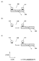
- (a) to (c) are schematic diagrams showing one aspect of an opening/closing mechanism of a sample inspection space by a sample holder in the inspection apparatus shown in FIG.
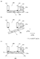
- FIG. (a) to (c) are schematic diagrams showing another aspect of the opening/closing mechanism of the sample inspection space by the sample holder.
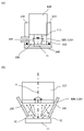
- FIG. 2 is a schematic diagram showing the shape of a sample holder in the inspection apparatus shown in FIG.
- FIG. 4 is a schematic diagram showing the shape of the specimen holder in a mode in which the external shape of the specimen holder is rod-shaped.
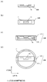
- FIG. 4 is a schematic diagram showing the shape of the specimen holder in a mode in which the external shape of the specimen holder is plate-like.
- FIG. 4 is a schematic diagram showing the shape of the specimen holder in a mode in which the external shape of the specimen holder is disc-shaped.
- FIG. 4 is a schematic diagram showing the shape of the specimen holder in a mode in which the external shape of the specimen holder is disc-shaped.
- (a) to (f) Schematic diagrams showing exemplary modes of fixing immunochromatographic test strips to specimen holders.
- (a) to (c) are schematic diagrams showing an example in which the attachment parts are compatible with a plurality of types of immunochromatographic test strips in the mode in which the attachment parts are provided on the sample holder.
- (a) and (b) are schematic diagrams showing one aspect of the vacuum interrupting mechanism in the inspection apparatus shown in FIG.
- FIG. 1 is a block diagram showing the configuration of an immunochromatographic test strip inspection system according to an embodiment of the present invention
- FIG. A photographic image showing the appearance of an inspection device for an immunochromatographic test strip fabricated as an observation example.
- An immunochromatographic test strip inspection device comprises configurations 1) to 4) of aspect (1) above. That is, the inspection apparatus of the present invention is an apparatus that uses metal microparticles by immunochromatography as a labeling substance and has at least the following 1) to 4). 1) An electron gun section for irradiating an immunochromatography test strip with an electron beam 2) An immunochromatography test strip is irradiated with an electron beam emitted from the electron gun section 1), and reflected electrons or secondary electrons from metal fine particles generated are detected.
- a sample inspection space 4 which can accommodate the detector part of the detector part 3) 2) and the part to be inspected of the immunochromatographic test strip, and which can be adjusted to a degree of vacuum of 100 pascal or less during the inspection of the immunochromatographic test strip.
- the inspection apparatus of the present invention has the sample inspection space of 3) above, it is desirable to shorten the time for adjusting the sample inspection space to a vacuum and/or to reduce the load on the vacuum pump (evacuating means).
- the volume of the sample inspection space (space volume) is small.
- the space volume refers to the volume of the inspection space of the inspection apparatus (the space into which the immunochromatographic test strip to be inspected is introduced during the inspection of the immunochromatographic test strip; sample inspection space), and the sample holder of 4) above into the inspection space. It means the volume obtained by subtracting the occupied volume when introduced, and the volume is preferably 1000 cubic centimeters or less, more preferably 500 cubic centimeters or less, and most preferably 300 cubic centimeters or less.
- a movable member is provided between the electron gun section of 1) above and the sample inspection space of 3) above, and when the specimen holder of above 4) is operated, 3 1) It has a mechanism (vacuum interrupting mechanism) that maintains the degree of vacuum of the electron gun unit regardless of changes in the degree of vacuum in the sample inspection space.
- a vacuum interrupting mechanism By providing a vacuum cut-off mechanism, even if the sample inspection space of 3) once becomes atmospheric pressure at the time of exchanging the immunochromatographic test strip, the electron gun part of 1) is maintained at a predetermined degree of vacuum, so that inspection can be started. In some cases, the time required for setting the sample inspection space to a predetermined degree of vacuum in 3) can be shortened.
- This movable vacuum cut-off mechanism is opened at the time when the immunochromatographic test strip is introduced into the sample inspection space in 3) and the inspection is started, and the electron beam emitted from the electron gun unit is directed to the inspected portion of the immunochromatographic test strip. is configured to be illuminated. Therefore, the member constituting the vacuum interrupting mechanism may be made of a material that does not transmit electron beams. However, the vacuum cut-off mechanism may be composed of a member made of a material having electron beam transparency.
- the sample inspection space is evacuated by a vacuum pump (evacuating means) during inspection of the immunochromatographic test strip, and the degree of vacuum is preferably 1000 pascals or less, more preferably 100 pascals or less.
- the degree of vacuum is preferably 10 ⁇ 4 pascals or higher, more preferably 10 ⁇ 2 pascals or higher.
- the range of the degree of vacuum of the sample inspection space in the present invention is preferably 10 -4 pascal or more and 1000 pascal or less, more preferably 10 -2 pascal or more and 100 pascal or less, and still more preferably 10 -2 pascal or more and 10 pascal or less. be.
- the electron gun section of 1) above is preferably adjusted to a vacuum in advance before inspection of the immunochromatographic test strip.
- the degree of vacuum of the electron gun is preferably 10 ⁇ 2 pascals or less, more preferably 10 ⁇ 4 pascals or less.
- a vacuum pump is used to previously adjust the electron gun section to a vacuum prior to inspection of the immunochromatographic test strip, and the above-described vacuum interrupting mechanism is provided to obtain the desired vacuum.
- the electron beam generator of the electron gun may be arranged in a vacuum tube preliminarily adjusted to the above-mentioned degree of vacuum.
- each user may prepare and use a vacuum pump, or the vacuum pump may be provided in advance as an accessory part of the inspection apparatus.
- any electron beam generator can be used for the electron gun.
- the electron beam generator of the electron gun is roughly classified into a field emission type, a Schottky type, and a thermionic emission type.
- the thermionic emission type it is preferable to use the thermionic emission type from the viewpoint of miniaturization of the entire apparatus.
- any mode of detecting metal fine particles in an immunochromatographic test strip may be used.
- the detection mode in an electron microscope is a backscattered electron mode, a secondary electron mode, or a fluorescent X-ray is detected. It may be a style to do.
- the detection mode by the reflected electron mode or the secondary electron mode is preferable. That is, in the inspection apparatus of the present invention, the detector section of 2) above is preferably a backscattered electron detector or a secondary electron detector.
- any method may be used to introduce the immunochromatographic test strip into the sample inspection space.
- a mechanism for introducing an immunochromatographic test strip into the sample inspection space ii) using a specimen holder having a plate-like (flat plate shape) or disk-like (disk-like) external shape, a plurality of immunochromatographic test strips on the specimen holder; and a mechanism for introducing an immunochromatographic strip into the sample inspection space by sliding or rotating the sample holder; iii) a structure in which the sample holder constitutes the bottom of the sample inspection space;
- a method of introducing an immunochromatographic test strip into a sample inspection space by opening and closing a sample holder (back cover) can be adopted.
- the mechanisms i) and ii) are preferred as mechanisms for easily maintaining the degree of vacuum in the sample inspection space. Also, by adopting a structure that utilizes the principle of differential pumping for adjusting the degree of vacuum in the sample inspection space and the electron gun section, it is possible to apply the method of iii).
- the sample holder has basic parts and attachment parts according to the shape of each immunochromatographic test strip.
- a structure is also preferred.
- the sample holder is configured to be able to hold various immunochromatographic test strips of various widths and lengths, and the attachment parts are designed to prevent gaps that may occur between the sample holder and individual immunochromatographic test strips. is adjusted so that the portion to be inspected of the immunochromatographic test strip is always positioned at the irradiation portion of the electron beam emitted from the electron gun portion (hereinafter simply referred to as the electron beam irradiation portion). .
- an operating mechanism for adjusting the position of the inspected portion of the immunochromatographic test strip so as to be positioned at the electron beam irradiation site is provided in 3). It may be provided in the sample inspection space, and the sample holder of 4) may be provided with the operating mechanism. Above all, it is preferable that the specimen examination space of 3) is provided with an operating mechanism capable of adjusting the position of the immunochromatographic test strip including the specimen holder of 4).
- the inspection apparatus of the present invention preferably has a mechanism for recognizing the position of the inspected portion of the immunochromatographic test strip by arbitrary means.
- a specific example of the position recognition method by the mechanism will be described below.
- the position recognition method that can be employed in the inspection apparatus of the present invention is not limited to the following specific examples.
- Immunochromato test strips that are currently in practical use usually have printed or uneven marks on the exterior parts so that the position of the part to be tested can be identified.
- the position of the immunochromatographic test strip (including the specimen holder) is recognized by reading the mark as an image of backscattered electrons or secondary electrons.
- Example of position recognition method (2) Marking the part to be inspected of the immunochromatographic test strip to be inspected beforehand with unevenness or paint that can be identified as an image of backscattered electrons or secondary electrons, and by reading it, the inspection can be performed accurately. identify the part.
- Example of Position Recognition Method (3) An optical camera mechanism is arranged in the inspection device to read the mark of the exterior part of the immunochromatographic test strip, and the position of the part to be inspected is recognized using the mark.
- Example of Position Recognition Method (4) An optical camera mechanism is arranged in the inspection apparatus to read the position of the control line of the immunochromatographic test strip, and the position of the inspected part is recognized using it as a mark.
- Example of position recognition method (5) A mark that can be identified as an optical image is attached in advance to the inspection part of the immunochromatographic test strip to be inspected, and by reading it, the inspection part is read as an image of reflected electrons or secondary electrons. Identify.
- examples (2), (4) and (5) are preferred methods of the position recognition method employed in the inspection device of the present invention.
- the inspection device of the present invention is used to detect metal fine particles in an immunochromatographic test strip, and fibers (such as nitrocellulose) that are the background in the backscattered electron image or secondary electron image obtained by the detector unit A configuration may be added to increase the contrast ratio with.
- the angle at which the immunochromatographic test strip is irradiated with the electron beam is preferably perpendicular to the upper surface of the immunochromatographic test strip. In some cases, an inclination in the range of 10° to 45° facilitates the detection of metal microparticles.
- the distance (working distance) between the objective lens located at the end of the electron gun and the inspected portion of the immunochromatography test strip, and the immunochromatography It is also preferable to fix the distance from the tested portion of the test strip to the detector portion (backscattered electron detector or secondary electron detector).
- the distance between the inspected part and the objective lens or the electron detector is variable in order to allow observation of the sample to be observed at various magnifications, but in the inspection apparatus of the present invention, Rather, it is preferable to be fixed in terms of simplification of device design.
- a mechanism that enables fine adjustment of the distance for adjusting the focus when detecting metal fine particles is not unnecessary. .
- a general immunochromatographic test strip structure has a membrane component inside a plastic casing that serves as a channel for the lateral flow method. Since the inner volume of the plastic housing containing the membrane component is included in the volume of the inspection device of the present invention when adjusting the sample testing space in 3) above to vacuum, the internal volume of the plastic housing containing the membrane component is small. Specifically, it is preferably 3 cubic centimeters or less, more preferably 2 cubic centimeters or less, and still more preferably 1 cubic centimeter or less.
- Non-Patent Document 1 when an immunochromatographic test strip is inspected using the inspection device of the present invention, it is preferable to apply an auxiliary liquid as shown in Non-Patent Document 1.
- the auxiliary liquid applicable to the immunochromatographic test strip inspection method using the inspection apparatus of the present invention improves the sharpness of the output result (analysis image) by data processing the image information obtained by the detector unit.
- the auxiliary liquid By applying the auxiliary liquid, it is possible to obtain analysis images with high contrast in the inspection of immunochromatographic test strips.
- the auxiliary liquid has a property of becoming conductive under the inspection conditions and/or a property of polymerizing to form a film by electron beam irradiation under the inspection conditions. effect can be obtained efficiently.
- the auxiliary liquid improves the clarity of the analysis image in the inspection of immunochromatographic test strips using the inspection device of the present invention.
- the auxiliary liquid preferably has a property of becoming conductive under the inspection conditions and/or a property of polymerizing to form a film by electron beam irradiation under the inspection conditions. More specifically, the auxiliary liquid has, as an essential component, selected from glycerin and glycerin substitutes; and at least one surface-active compound selected from monosaccharides, disaccharides, salts, and buffers as an optional component.
- Glycerin is a trihydric alcohol (so-called polyhydric alcohol), has a hydroxyl group in its molecule, and is a low vapor pressure substance. Also, glycerin is viscous. Substances with these characteristics can be included in supplementary liquids as replacement ingredients for glycerin.
- glycerin substitutes include, for example, polyethylene glycol, polyvinyl alcohol, triglycerides, polyresorcinol, polyphenols, tannic acid, urushiol, saponin, and the like. Glycerin and glycerin substitutes may be used singly or in combination of two or more.
- polysorbates are intended to be those produced by reacting sorbitan fatty acid ester (nonionic surfactant) with ethylene oxide.
- sorbitan fatty acid ester nonionic surfactant
- Currently available polysorbates include polysorbate 20 (Tween 20), polysorbate 40 (Tween 40), polysorbate 60 (Tween 60), polysorbate 65 (Tween 65), polysorbate 80 (Tween 80), polysorbate 85 (Tween 85) ), but the polysorbates that can be included in the auxiliary liquid are not limited to these.
- Substances classified as nonionic surfactants, like polysorbates, can be included in the auxiliary liquid as alternative components for polysorbates.
- polysorbate substitutes include, for example, polyoxyethylene alkyl ether, polyoxyethylene hydrogenated castor oil, polyoxyethylene mono fatty acid ester, sucrose fatty acid ester, polyglycerin fatty acid ester, alkyl polyglycoside, N-methyl Alkyl glucamides and the like can be mentioned.
- Polysorbates and polysorbate substitutes may be used singly or in combination of two or more.
- Monosaccharides include, for example, glucose and fructose.
- Disaccharides include, for example, sucrose, trehalose and the like.
- salts include imidazolium salts, pyridinium salts, piperidinium salts, pyrrolidinium salts, quaternary ammonium salts and the like.
- buffers include acetate buffer (acetic acid/sodium acetate buffer), phosphate buffer (phosphate/sodium phosphate buffer), citrate buffer (citric acid/sodium citrate buffer), citric acid phosphate buffer (citric acid/sodium phosphate buffer), borate buffer, tartrate buffer, Tris buffer and the like. These monosaccharides, disaccharides, salts, and buffers may be used singly or in combination of two or more.
- An essential component consisting of at least one compound selected from glycerin, glycerin substitutes, polysorbates, and polysorbate substitutes is preferably contained in the auxiliary liquid in an amount of 0.01% to 10% by weight, and 0.1 More preferred is an embodiment containing from weight percent to 2 weight percent.
- the inspection device of the present invention is equipped with an auxiliary liquid supply unit that supplies the above-described auxiliary liquid to the immunochromatographic test strip.
- a preferred embodiment is a system that includes a nozzle part and a solution storage part like an ink cartridge used in an inkjet printer, and ejects an appropriate amount of auxiliary liquid to the tested part of the immunochromatographic test strip before the test.
- the auxiliary liquid may be supplied so as to permeate the entire membrane of the immunochromatographic test strip, and only the part to be inspected, that is, the auxiliary liquid captures reflected electrons or secondary electrons from the metal fine particles generated by electron beam irradiation. It is also possible to supply only to the area portion from which image information is to be acquired.
- the auxiliary liquid supplied is preferably 100 microliters or less per test, more preferably 30 microliters, and when the auxiliary liquid is supplied only to the part to be inspected, it is preferably 10 microliters or less, and more preferably 10 microliters or less. It is preferably 1 microliter or less.
- a mechanism that enables such a small amount of auxiliary liquid to be ejected for example, a system in which a piezo element is provided in the auxiliary liquid supply section and deformation of the piezo element by voltage application can be used.
- auxiliary liquid By applying the auxiliary liquid described above, it is possible to perform a good inspection of the immunochromatographic test strip using the inspection apparatus of the present invention.
- an electrical grounding component for the membrane component that allows electrical conduction between the membrane component of the immunochromatographic test strip and any metal components that make up the testing device.
- An immunochromatographic test strip inspection device using immunochromatographic metal fine particles as a labeling substance comprising at least the following 1) to 4
- the specimen holder in 4) below i) has a rod-like (rod-like) external shape, and has a mechanism for introducing an immunochromatographic test strip into the specimen examination space in 3) below from the side of the inspection device, ii) plate-shaped (flat plate (shape) or disk-shaped (disk-shaped) external shape, a mechanism for introducing an immunochromatographic strip into the sample inspection space of 3) below by sliding or rotating the sample holder, and iii) the sample holder is in the sample inspection space It has a structure that constitutes the bottom part, and has a mechanism for introducing an immunochromatographic test strip into the sample inspection space by opening and closing the specimen holder (back cover) from below (bottom part) of the sample inspection space, These have a structure including attachment parts configured to be able to use various immunochromatographic test strips,
- An electron gun unit for irradiating an immunochromatographic test strip with an electron beam 2) A detector for detecting reflected electrons or secondary electrons from fine metal particles generated by irradiating an immunochromatographic test strip with an electron beam emitted from the electron gun in 1) A sample inspection space that can accommodate the detector part of part 3) 2) and the part to be inspected of the immunochromatography test strip, and can be adjusted to a degree of vacuum of 100 pascal or less during the inspection of the immunochromatography test strip 4) Immunochromatography A specimen holder for introducing a test strip from the atmospheric pressure condition outside the apparatus into the specimen examination space of 3).
- the principle of immunochromatography and the detection method of the detection target are not particularly limited.
- a representative embodiment includes immunochromatography using a labeled antibody carrying fine metal particles as a labeling substance and a capture antibody having the property of binding to a complex of the labeled antibody and a substance to be detected.
- specific aspects of immunochromatography in the present invention are not limited to this.
- the number of metal fine particles can be measured visually using the inspection apparatus of the present invention.
- the number of metal microparticles can be measured automatically using an image processing technique.
- the shape and size of metal microparticles contained in an immunochromatographic test strip, or the size, contour shape, luminance ratio with the surroundings, frequency characteristics of luminance information, and other image feature values of metal microparticle images appearing in analysis images indicate that they are metal microparticles.
- a method for determining can be used.
- an image recognition system using machine learning or deep learning can be used to count the number of metal microparticles.
- An automatic analysis system that identifies metal microparticles by identifying microparticles is also possible.
- the pattern recognition method using the frequency characteristic of the luminance information of the metal fine particle image, the size, and the feature amount of the contour shape image, or the method using artificial intelligence are preferable.
- FIG. 1 is a schematic diagram showing the configuration of an immunochromatographic test strip inspection apparatus according to an embodiment of the present invention.
- an immunochromatographic test strip inspection apparatus 100 (hereinafter also simply referred to as inspection apparatus 100) of this embodiment includes an electron gun section 110, a detector section 120, a sample inspection space 130, and a sample holder. 140.
- Electron Gun Section 110 irradiates an electron beam B onto the immunochromatographic test strip TS to be inspected.
- the electron gun section 110 has a housing 111, and an electron beam generating section (electron gun) 112 is arranged inside the housing 111.
- An objective lens 113 is arranged at the lower end of the housing 111, and the electron beam B emitted from the electron beam generator 112 is directed through condenser lenses 114a and 114b and a condenser aperture provided in the housing 111.
- an electronic optical component such as a deflection coil 116, and through an objective lens 113, an immunochromatographic test strip TS (more specifically, an inspected portion of an immunochromatographic test strip TS (test line, control line, etc., labeling substance is irradiated to the portion where the metal fine particles are present)).
- the configuration and arrangement of the electron optical system (electron optical component group) in the housing 111 shown in FIG. 1 are merely examples, and the configuration and arrangement of the electron optical system in a general electron microscope can be appropriately adopted. .
- a vacuum evacuation means 150a is attached to the housing 111, and the inside of the housing 111 can be adjusted to a predetermined degree of vacuum by evacuating in the direction of the arrow.
- the evacuation means 150a is composed of a vacuum pump.
- a fine hole is provided between the electron gun section 110 and the sample inspection space 130 to provide a bottleneck for gas molecule flow, and the principle of differential pumping is used.
- the diameter of the orifice is preferably 1 ⁇ m to several hundred ⁇ m.
- an orifice 117 for differential pumping is formed in the objective lens 113 (at the bottom).
- a vacuum cutoff mechanism which will be described later, is provided between the electron gun section 110 and the sample inspection space 130 .
- differential pumping is more effective if orifices are provided in multiple stages, but in the inspection apparatus 100 shown in FIG. A plurality of orifices may be provided as long as they can pass through. However, as shown in FIG. 1, even if the number of orifices is one, the effect of differential pumping can be sufficiently obtained.
- FIG. 2 is a schematic diagram showing the configuration of the inspection apparatus 100 in this mode.
- the electron beam generator 112 is provided inside a vacuum tube 118 that has been previously adjusted to a degree of vacuum of 10 ⁇ 2 pascals or less.
- the evacuation means 150a can be omitted, so that the configuration required for the operation of the inspection apparatus can be simplified.
- the same configuration as the configuration shown in FIG. 1 can be adopted for other configurations, and the same applies to various modifications described later. Therefore, below, each component will be described exclusively with reference to the inspection apparatus 100 shown in FIG.
- the detector section 120 detects reflected electrons or secondary electrons from fine metal particles generated by irradiating the immunochromatographic test strip TS with the electron beam B emitted from the electron gun section 110 .
- the detector section 120 is a backscattered electron detector 120A, and the backscattered electron detector 120A is provided below the objective lens 113.
- a black circle mark shown below the objective lens 113 is a sealing material (O-ring).
- the detector section 120 may be composed of one type of detector, or may be composed of a combination of multiple types of detectors. Specifically, the detector section 120 may be either or both of a backscattered electron detector and a secondary electron detector, and may be combined with a fluorescent X-ray detector. In addition, when the detector unit 120 is configured by combining a plurality of types of detectors, their arrangement (specifically, the positional relationship with the objective lens 113, the positional relationship between detectors, etc.) can be appropriately determined by those skilled in the art. can be designed.
- the specimen inspection space 130 can accommodate the detector section 120 and the inspected portion of the immunochromatographic test strip TS, and can be adjusted to a degree of vacuum of 100 pascals or less when the immunochromatographic test strip TS is inspected. It is
- the sample inspection space 130 is formed by being substantially surrounded by the facing side wall members 160, the lower bottom surface of the electron gun section 110, and the upper surface of the sample holder 140.
- An objective lens 113, a detector section 120, and an immunochromatographic test strip TS fixed to a sample holder 140 are accommodated therein.
- the upper surface of the immunochromatographic test strip TS fixed to the specimen holder 140 and the upper surface of the specimen holder 140 form substantially the same plane.
- a vacuum exhaust means 150b is attached to the side wall member 160, and the sample inspection space 130 can be adjusted to a degree of vacuum of 100 pascal or less during inspection of the immunochromatographic test strip TS by exhausting in the direction of the arrow.
- the evacuation means 150b is composed of a vacuum pump.
- the specimen holder 140 is for introducing the immunochromatographic test strip TS into the specimen testing space 130 from the atmospheric pressure condition outside the testing device 100 .
- the specimen holder 140 has a substantially rectangular shape when viewed from the side, and has a concave portion formed at an arbitrary position on the upper surface. TS can be fixed.
- the side view width (the length in the left-right direction) of the specimen holder 140 is substantially the same as the length to both side ends of the opposing side wall members 160.
- the shape and size of the specimen holder 140, and the manner of fixing the immunochromatographic test strip TS to the specimen holder 140 are not limited thereto. Details will be described later.
- the specimen holder 140 seals the specimen testing space 130 by contacting the lower bottom surface of the side wall member 160 during testing of the immunochromatographic test strip TS.
- the seal portion 160a on the lower bottom surface of the side wall member 160, the sealed state is further ensured, so that the degree of vacuum of the sample inspection space 130 can be more easily adjusted by the evacuation means 150b.
- the specimen holder 140 is released from contact with the lower bottom surface of the side wall member 160 . That is, in the inspection apparatus 100 , the sample holder 140 is movable, and the sample inspection space 130 can be opened at the bottom by the operation of the sample holder 140 . In other words, in the inspection apparatus 100, the bottom of the sample inspection space 130 is openable, and the sample inspection space 130 becomes an atmospheric atmosphere when the immunochromatographic test strip TS inspection is completed and when the immunochromatographic test strip TS is replaced. is one of the features.
- FIG. 3(a) is a schematic diagram showing a state in which the sample inspection space 130 is closed, and the sample holder 140 makes the sample inspection space 130 in a sealed state by coming into contact with the lower bottom surfaces of the facing side wall members 160.
- FIG. 3(a) is a schematic diagram showing a state in which the sample inspection space 130 is closed, and the sample holder 140 makes the sample inspection space 130 in a sealed state by coming into contact with the lower bottom surfaces of the facing side wall members 160.
- FIG. 3(b) is a schematic diagram showing a state in which the sample inspection space 130 is opened.
- the bottom of space 130 is open.
- the specimen holder 140 may be moved in the opposite direction (to the left) or in the Y direction (the direction through the plane of FIG. 3).
- the movement of the specimen holder 140 may be in the X direction (horizontal direction) or only in the Y direction, or may be a combination of the Z direction (vertical direction) and the X direction as shown in FIG. Also good. As a modification of the latter, a combination of the Z direction and the Y direction may be used, or a combination of the Z direction and the X direction may be further combined with movement in the Y direction.
- 3A to 3C omit a mechanism for enabling movement of the sample holder 140, but the configuration and arrangement of such a mechanism can be appropriately designed by those skilled in the art. can do.
- a convex portion (or concave portion) having a predetermined shape is provided at an arbitrary position on the side of the specimen holder 140, and the user grips the convex portion (or concave portion) to move the specimen holder 140 in a desired direction. You may make it move to.
- FIGS. 4A to 4C are schematic diagrams showing another aspect of the opening/closing mechanism of the sample inspection space 130 by the sample holder 140.
- a support member 161 is provided on the side end surface of the side wall member 160 (the end surface on the side opposite to the sample inspection space 130), and the support member 161 has a rotation shaft portion 161a.
- the support member 161 may be arranged on the left side of the sample inspection space 130 .
- the specimen holder 140 is a structure having a connecting portion 140a into which the rotating shaft portion 161a can be fitted. It is configured to be rotatable.
- FIG. 4(a) is a schematic diagram showing a state in which the sample inspection space 130 is closed, and the sample holder 140 makes the sample inspection space 130 in a sealed state by coming into contact with the lower bottom surfaces of the facing side wall members 160.
- FIG. 4(a) is a schematic diagram showing a state in which the sample inspection space 130 is closed, and the sample holder 140 makes the sample inspection space 130 in a sealed state by coming into contact with the lower bottom surfaces of the facing side wall members 160.
- FIG. 4(b) is a schematic diagram showing a state in which the specimen inspection space 130 is open, and the specimen holder 140 is moved downward from the state shown in FIG. By rotating in the direction, the bottom of the sample inspection space 130 is opened.
- the portion including the fixing portion of the immunochromatographic test strip TS and the portion including the connection portion 140a connected to the rotation shaft portion 161a of the support member 161 are shown in FIG. and (b), or may be configured such that separate structures 141 and 142 are connected by any connecting means as shown in FIG. 4(c).
- FIGS. 5A and 5B are schematic diagrams respectively showing the shape of the specimen holder 140 in the inspection apparatus 100 shown in FIG. 1 when viewed from the side and viewed from the top.
- a rectangular frame F indicated by broken lines schematically indicates a portion where the end surface of the side wall member 160 is positioned when the sample inspection space 130 is closed.
- FIGS. 6(b), 7(b) and 8(b) which will be described later.
- the specimen holder 140 has a substantially rectangular external shape, which is similar to the shape of a specimen table (specimen stage) used in conventional electron microscopes. It can be said that there are on the other hand, in conventional electron microscopes, the sample stage normally moves (X, Y) in the plane, moves in the vertical direction (Z), and tilts (T) and rotates (R) the mounted sample.
- the inspection apparatus 100 of the present embodiment exclusively inspects the immunochromatographic test strip TS, so that the sample holder 140 does not require complicated operations, and is relatively simple. However, it is sufficient if combinations of movements in the X, Y, and Z directions are possible.
- the sample holder 140 has a high degree of freedom in its structure.
- the external shape of the specimen holder 140 may be the substantially rectangular shape described above, or may be rod-shaped, plate-shaped, disc-shaped, or the like. Also good.
- the structure having the above shape may be used as a portion including the fixing portion of the immunochromatographic test strip TS, and this may be combined with another structure to form the specimen holder 140 consisting of a plurality of structures.
- FIGS. 5(c) and (d) are schematic diagrams showing an example of the latter mode.
- the sample holder 140 shown in FIGS. 5(c) and 5(d) has a structure 141 which is a portion including the fixed portion of the immunochromatographic test strip TS, and a ring-shaped structure configured to allow the structure 141 to be inserted therein. It consists of a body 143 .
- the bottom of the structure 143 is not drawn in FIG. 5(d), but as shown in FIG. 5(c), the bottom of the structure 143 is closed and the top is is open.
- the configuration of the structure 141 is the same as that of the specimen holder 140 described with reference to FIGS. 5(a) and 5(b).
- the structure 143 constitutes the body portion of the specimen holder 140, and when the immunochromatographic test strip TS is tested, the upper surface of the structure 143 contacts the lower bottom surface of the side wall member 160, thereby creating a specimen testing space. 130 is closed. Therefore, in this modified example, the side wall member 160 is arranged so as to surround the housing 111 of the electron gun section 110 or in the lower portion of the housing 111 so as to match the shape of the structure 143 . As a result, when the sample inspection space 130 is closed, the portion where the end surface of the side wall member 160 is positioned is schematically shown as a circular frame F' indicated by broken lines in FIG. 5(d). Comparing the frame F' shown in FIG. 5D and the frame F shown in FIG.
- a structure 141 which is a portion including a fixing portion of the immunochromatographic test strip TS, is separately provided from the structure 143 constituting the body portion of the sample holder 140. Therefore, there is an advantage that it is relatively easy to further dispose a position adjusting mechanism such as the above-described XY table.
- a pedestal (stage portion) of an XY table is provided inside the structure 143 and below the structure 141, and the pedestal is arranged in the X direction (longitudinal direction of the structure 141).
- the structure 143 forming the bottom of the sample inspection space 130 is kept at its position, and the structure 143 is moved by the operation of the XY table.
- the position of 141 in the X direction and the Y direction the position of the inspected portion of the immunochromatographic test strip TS can be adjusted so as to be positioned at the electron beam irradiation site.
- FIGS. 6(a) and 6(b) are schematic diagrams showing the side view and top view of the specimen holder 140 in a mode in which the appearance of the specimen holder 140 is rod-shaped, respectively.
- the specimen holder 140 has a longer length in the X direction than the embodiment shown in FIGS. 5(a) and 5(b).
- a recess for fixing the immunochromatographic test strip TS is formed on the end side (right side).
- the movement of the specimen holder 140 is not limited to the X direction, and movement in the Y and Z directions may be combined.
- the sample holder 140 shown in FIGS. 6(c) and 6(d) has a structure 141 which is a portion including the fixed portion of the immunochromatographic test strip TS, and a ring-shaped structure configured to allow the structure 141 to be inserted therein. It consists of a body 143 .
- the bottom of the structure 143 is not drawn in FIG. 6(d), but as shown in FIG. 6(c), the bottom of the structure 143 is closed and the top is open.
- the configuration of the structure 141 is the same as that of the specimen holder 140 described with reference to FIGS.
- the structure 143 constitutes the body portion of the specimen holder 140, and when the immunochromatographic test strip TS is tested, the upper surface of the structure 143 contacts the lower bottom surface of the side wall member 160, thereby creating a specimen testing space. 130 is closed. Therefore, in this modified example, the side wall member 160 is arranged so as to surround the housing 111 of the electron gun section 110 or in the lower portion of the housing 111 so as to match the shape of the structure 143 . As a result, when the sample inspection space 130 is closed, the portion where the end surface of the side wall member 160 is positioned is schematically shown as a circular frame F' indicated by broken lines in FIG. 6(d). Comparing the frame F' shown in FIG. 6D and the frame F shown in FIG. It is possible to set it within the preferred range mentioned above.
- FIGS. 7(a) and 7(b) are schematic diagrams showing the side view and top view of the specimen holder 140 in a mode in which the external shape of the specimen holder 140 is plate-like.
- the specimen holder 140 has a longer Y-direction length than the embodiment shown in FIGS. 6(a) and 6(b).
- a plurality of recesses (five as an example) for fixing the immunochromato test strip TS are formed on the end portion side (right side).
- a plurality of immunochromatographic test strips TS fixed to one specimen holder 140 can be tested. Also, when opening/closing the sample inspection space 130 and when exchanging the immunochromatographic test strip TS, the sample holder 140 may be operated by appropriately combining movements in the X, Y and Z directions.
- the size of the specimen holder 140 can be longer in the X direction and/or the Y direction than the specimen stage used in conventional electron microscopes.
- FIGS. 8(a) and 8(b) are schematic diagrams showing the side view and top view of the specimen holder 140, respectively, in a mode in which the specimen holder 140 has a disk-like appearance.
- the sample holder 140 has a plurality of (eight as an example) concave portions for fixing the immunochromatographic test strips TS radially with respect to the central portion thereof.
- a plurality of immunochromatographic test strips TS fixed to one specimen holder 140 can be tested by making members such as the section 110 and the side wall member 160 movable (rotatable). Also, when opening/closing the sample inspection space 130 and when exchanging the immunochromatographic test strip TS, the sample holder 140 may be operated by appropriately combining movements in the X, Y and Z directions.
- the manner of fixing the immunochromatographic test strip TS to the specimen holder 140 is not limited to the manner described above, and various modifications can be made.
- the specimen holder 140 (see FIGS. 6(a) and 6(b)) having a rod-like appearance will be described as modified examples shown in FIGS. 9(a) to 9(f).
- the immunochromatographic test strip TS is fixed to the concave portion formed in the specimen holder 140 in the same manner as shown in FIG. 6(a), and the upper surface of the specimen holder 140 and the immunochromatographic test strip The top surfaces of the TSs form substantially the same plane.
- the depth of the recess formed in the sample holder 140 is smaller than the height of the immunochromatographic test strip TS, and when the immunochromatographic test strip TS is fixed, a part of the immunochromatographic test strip TS is protrudes from the upper surface of the specimen holder 140 .
- the volume of the specimen testing space 130 is equal to the volume corresponding to the portion of the immunochromatographic test strip TS protruding from the upper surface of the specimen holder 140. will decrease.
- the immunochromatographic test strip TS is placed on the upper surface of the specimen holder 140.
- complicated operations are not required for the sample holder 140, so the mode like this aspect can also be adopted.
- the immunochromatographic test strip TS should be prevented from unintentionally deviating from the predetermined position of the specimen holder 140 or falling from the specimen holder 140.
- the attachment part 144 as shown in FIG. 9(d) is provided on the specimen holder 140, for example, as shown in FIG.
- the upper surface may be made to form substantially the same plane, and as shown in FIG. A part of the immunochromatographic test strip TS may protrude from the upper surface of the attachment part 144 (the upper surface of the specimen holder 140) while the TS is fixed.
- the attachment part 144 may be compatible with one type of immunochromatographic test strip, or may be compatible with a plurality of types of immunochromatographic test strips. Also good.
- FIGS. 10(a) to 10(c) are schematic diagrams showing the configuration of the latter mode.
- the attachment part 144 provided on the sample holder 140 is compatible with immunochromatographic test strips TS1, TS2, and TS3 having three different external dimensions.
- the attachment part 144 can be adjusted so that the positions of the parts to be inspected M1, M2, M3 (typically test lines) are substantially the same in a state where the immunochromatographic test strips TS1 to TS3 are fixed. It is In FIGS. 10A to 10C, this is conceptually indicated by a rectangular frame P with dashed lines.
- the orifice 117 for differential pumping is formed in the objective lens 113 (at the bottom).
- the orifice is fitted with an electron beam permeable film (for example, a collodion film) that can withstand vacuum and is permeable to electron beams.
- an electron beam permeable film for example, a collodion film
- such an electron beam permeable film is not an essential component.
- FIGS. 11(a) and 11(b) are schematic diagrams showing one aspect of the vacuum cut-off mechanism in the inspection device 100.
- FIG. 11(a) is schematic diagrams showing one aspect of the vacuum cut-off mechanism in the inspection device 100.
- the backscattered electron detector 120A is attached to the position control means 121, and the position control means 121 moves backscattered electrons by moving in the X direction.
- the detector 120A is configured to be movable in the horizontal direction. Further, the backscattered electron detector 120A has a space 122 through which the electron beam B can pass at a predetermined position corresponding to the orifice 117 .
- the space 122 in the closed state of the sample inspection space 130, the space 122 is on the optical path (downward arrow) of the electron beam B, and the electron beam B is directed to the immunochromatographic test strip TS. Irradiation is possible.
- the position control means 121 moves in the direction of the arrow to change the position of the backscattered electron detector 120A. is positioned on the optical path of the electron beam B (in other words, the orifice 117 is blocked by the upper surface of the backscattered electron detector 120A), thereby spatially blocking the space between the electron gun section 110 and the sample inspection space 130. be. Thereby, the degree of vacuum in the housing 111 of the electron gun section 110 can be maintained.
- the backscattered electron detector 120A When the sample inspection space 130 is changed from the open state to the closed state again, the backscattered electron detector 120A remains in the state shown in FIG. (preliminary evacuation) can be performed. As a result, the sample inspection space 130 can be brought to a desired degree of vacuum (or approximately the same degree of vacuum) in a short time while maintaining the degree of vacuum inside the housing 111 of the electron gun section 110 . Thereafter, when the immunochromatographic test strip TS is inspected, the position of the backscattered electron detector 120A is set to the state shown in FIG. is secured, and the electron beam B is irradiated to the immunochromatographic test strip TS.
- the configuration of the position control means 121 and the mechanism for changing the position of the backscattered electron detector 120A in this embodiment are not limited to the embodiments shown in FIGS. The design can be changed as appropriate.
- FIGS. 12(a) and 12(b) are schematic diagrams showing another aspect of the vacuum cut-off mechanism in the inspection device 100.
- FIG. 12(a) is schematic diagrams showing another aspect of the vacuum cut-off mechanism in the inspection device 100.
- the backscattered electron detector 120A is attached to the position control means 121 via the vacuum cut-off member 170, and the position control means 121 operates in the X direction. , the backscattered electron detector 120A can be moved in the horizontal direction.
- the objective lens 113 is provided with a storage member 171 configured to accommodate the backscattered electron detector 120A on the side opposite to the side where the vacuum cutoff member 170 is located.
- the space 122 of the backscattered electron detector 120A is on the optical path (downward arrow) of the electron beam B, and the immunochromatographic test strip It is possible to irradiate the TS with an electron beam B.
- the position control means 121 moves in the direction of the arrow to change the position of the backscattered electron detector 120A.
- the vacuum shielding member 170 is positioned on the optical path of the electron beam B (in other words, the upper surface of the vacuum shielding member 170 closes the orifice 117). It is spatially isolated from the sample inspection space 130 . Thereby, the degree of vacuum in the housing 111 of the electron gun section 110 can be maintained.
- the sample inspection space 130 When the sample inspection space 130 is closed again from the open state, the sample inspection space 130 is closed while the backscattered electron detector 120A is housed in the storage member 171 (the state shown in FIG. 12B). can be exhausted (preliminary exhaust). As a result, in this embodiment, the sample inspection space 130 can be brought to a desired degree of vacuum (or approximately the same degree of vacuum) in a short time while maintaining the degree of vacuum in the housing 111 of the electron gun section 110. In addition, the backscattered electron detector 120A and / or orifice due to scattered matter that may be generated from the immunochromatographic test strip TS during preliminary evacuation (for example, scattered matter due to moisture etc. contained in the tested part of the immunochromatographic test strip TS) 117 contamination can be suppressed.
- the immunochromatographic test strip TS to be inspected (especially, the part to be inspected) is not in a sufficiently dry state to the extent that some kind of spatter does not occur in the process of being exposed from atmospheric pressure conditions to vacuum conditions (possible 12), it is more preferable to employ the aspect shown in FIG. 12 as the vacuum cut-off mechanism.
- the configuration of the position control means 121, the vacuum blocking member 170, and the storage member 171 in this embodiment, and the mechanism for changing the position of the backscattered electron detector 120A and storing the backscattered electron detector 120A in the storage member 171 are as follows: , FIGS. 12(a) and 12(b), and those skilled in the art can make appropriate design changes.
- FIGS. 13A and 13B are schematic diagrams showing configuration examples of this embodiment.
- the inner wall member 180 is arranged to surround both ends of the backscattered electron detector 120A provided below the objective lens 113.
- FIG. since the inner wall member 180 is arranged to be inclined from the upper end to the lower end, as indicated by a plurality of arrows in the enlarged view of the essential part in FIG. It is configured to gather in a space including the upper surface of the portion to be inspected of the TS. This can improve the brightness (brightness) of the obtained image information (analysis image) as compared with conventional electron microscopes (for example, desktop scanning electron microscopes).
- the backscattered electron detector 120A when the backscattered electron detector 120A is a semiconductor type (a detector made of a semiconductor crystal), the backscattered electron detector 120A detects electrons having an energy of a certain level or more (2 to 3 kV or more as an example). and does not react to electrons with less energy. Therefore, by providing the inner wall member 180, the backscattered electron detector 120A captures more electrons having energy equal to or higher than the certain level, thereby increasing the brightness of the obtained image information.
- the backscattered electron detector 120A when the backscattered electron detector 120A is a semiconductor type (a detector made of a semiconductor crystal), the backscattered electron detector 120A detects electrons having an energy of a certain level or more (2 to 3 kV or more as an example). and does not react to electrons with less energy. Therefore, by providing the inner wall member 180, the backscattered electron detector 120A captures more electrons having energy equal to or higher than the certain level, thereby increasing the brightness of the obtained image information.
- the arrangement of the inner wall member 180 which is completely different from the concept of the electronic discrimination method, increases the brightness of the image information. It is possible to increase the contrast with the metal fine particles of As a result, it is possible to achieve an improvement in detection sensitivity and an improvement in the accuracy of determination results.
- the material of the inner wall member 180 is not particularly limited, but from the viewpoint of making it easier to generate more scattered electrons, it is made of an element with a relatively large atomic weight such as Au (gold), or the surface (immunochromatographic test strip It is more preferable that the side surface) is coated.
- the inner wall member 180 may be configured to be movable within the sample inspection space 130 by an arbitrary moving means (not shown). , can be retracted to a position that does not interfere with various operations (operations) of the inspection apparatus 100 .
- ⁇ Auxiliary liquid supply unit> the configuration of arranging the inner wall member 180 described above can be more effective in the aspect of applying the auxiliary liquid. That is, in the space where the inner wall member 180 is provided in the sample inspection space 130 and the conditions are such that the scattered electrons SE are more likely to occur, the formation of the coating on the inspected portion of the immunochromatographic test strip TS to which the auxiliary liquid is applied is more likely. can proceed efficiently.
- FIG. 14(a) and (b) are schematic diagrams showing a mode in which an auxiliary liquid supply unit is provided in the sample inspection space 130 in the inspection apparatus 100.
- FIG. 14(a) and (b) are schematic diagrams showing a mode in which an auxiliary liquid supply unit is provided in the sample inspection space 130 in the inspection apparatus 100.
- the auxiliary liquid supply unit 190 shown in FIGS. 14(a) and 14(b) has a mechanism and parts for applying the auxiliary liquid (aqueous solution of the surfactant compound described above) to the tested portion of the immunochromatographic test strip TS. ing. Specifically, as shown in the enlarged view of the main part on the right side of FIG. A predetermined amount of the auxiliary liquid NS contained in the solution containing section 192 is ejected from the nozzle section 191 using the deformation of the element 193, and the auxiliary liquid NS can be applied to the tested portion of the immunochromatographic test strip TS. ing. As described above, the configuration of such an auxiliary liquid supply unit can adopt a configuration used in an inkjet printer, and a person skilled in the art can appropriately change the design.
- the auxiliary liquid supply unit 190 is configured to be movable within the sample inspection space 130 by any moving means, and when the auxiliary liquid NS is applied (inspection (before testing), the nozzle portion 191 is aligned with the inspected portion of the immunochromatographic test strip TS, and after applying the auxiliary liquid NS (at the time of inspection), the optical path of the electron beam B irradiated to the immunochromatographic test strip TS is set to It can be retracted to a position where it will not be blocked.
- auxiliary liquid supply section is provided within the sample inspection space 130 .
- an auxiliary liquid supply unit may be provided outside the sample inspection space 130 . It comprises mechanisms and components for applying the auxiliary liquid NS to the tested portion of the test strip TS.
- the sample inspection space 130 can be opened at its bottom by the operation of the sample holder 140.
- a preliminary evacuation space is provided separately from the sample inspection space 130. You can do it.
- the sample holder 140 does not contact the lower bottom surface of the side wall member 160 , and a pre-exhaust space for inserting and removing the sample holder 140 is provided at an arbitrary position of the side wall member 160 .
- the sample holder 140 with the immunochromatographic test strip TS to be inspected fixed, enters the sample inspection space 130 through a portion (also called a gate valve) that communicates with the sample inspection space 130 from the preliminary evacuation space.
- the insertion introduces the immunochromatographic test strip TS into the sample test space 130 .
- the distance (working distance) between the objective lens 113 located at the end of the electron gun section 110 and the inspected portion of the immunochromatographic test strip TS is fixed to a constant value. This is desirable from the viewpoint of simplification of the mechanism and miniaturization of the device.
- a mechanism that enables fine adjustment of the distance for adjusting the focus when detecting the metal fine particles that are labeling substances (for example, during inspection, the immunochromatographic test strip TS can be moved (finely moved) in the X and Y directions. mechanism) may be provided.
- a mechanism for assisting the opening and closing of the bottom portion of the sample inspection space 130 by the operation of the sample holder 140 for example, a mechanism for assisting the contact between the sample holder 140 and the lower bottom surface of the side wall member 160 and the elimination thereof) may be provided. good.
- FIG. 15 is a block diagram showing the configuration of an immunochromatographic test strip inspection system according to an embodiment of the present invention.
- the immunochromatographic test strip inspection system 300 of this embodiment includes an inspection device 100 and an analysis device 200 .
- the inspection device 100 As the inspection device 100, the inspection device 100 of the present embodiment described with reference to FIGS. 1 to 14 can be used.
- the analysis device 200 includes a control section 210 , an image acquisition section 220 , a data processing section 230 and an output section 240 .
- the control unit 210 controls the operations of at least the electron gun unit 110, the detector unit 120, the sample inspection space 130, and the sample holder 140 of the inspection apparatus 100.
- Information (data) regarding control of the inspection apparatus 100 by the control unit 210 can be transmitted to the data processing unit 230 .
- the image acquisition unit 220 acquires image information obtained by the detector unit 120 of the inspection device 100 .
- Image information (image data) acquired by the image acquiring section 220 can be transmitted to the data processing section 230 .
- the data processing unit 230 can process data from the control unit 210 and the image acquisition unit 220 and transmit the processing result to the output unit 240 .
- the output unit 240 outputs the processing result of the data processing unit 230.
- the output unit 240 for example, a liquid crystal display device, a printer, or the like is used.
- a recording device that records the processing result of the data processing unit 230 on a recording medium such as a USB memory may be used as the output unit 240 .
- the inspection system 300 analyzes the state of the inspected portion of the immunochromatographic test strip TS.
- the detection of the metal microparticles which are the labeling substances in the immunochromatographic test strip TS, is performed by displaying an image of the inspected portion of the immunochromatographic test strip TS on the output unit 240 and visually counting the number of metal microparticles in the image.
- the number of metal fine particles obtained by displaying an image of the inspected portion of the immunochromatographic test strip TS on the output unit 240 and identifying the metal fine particles in the image using artificial intelligence or the metal An arbitrary physical quantity correlated with the number of fine particles may be output.
- the inspection system 300 is an automatic analysis system that automatically measures the metal microparticles in the immunochromatographic test strip TS by means of artificial intelligence. Furthermore, by combining such an inspection system 300 with an industrial robot or the like that is currently in practical use, the user only needs to place the immunochromatographic test strip TS at a predetermined location, and other operations can be performed. could be an automated immunochromatographic test strip inspection system.
- An immunochromatographic test strip inspection apparatus having the configuration described with reference to FIG. 1 was manufactured as a trial, and a portion to be inspected was observed using a commercially available immunochromatographic test strip.
- FIG. 16(a) is a photographic image showing the external appearance of the immunochromatographic test strip inspection device that was produced on a trial basis in this observation example, and shows a state in which the target immunochromatographic test strip is introduced into the sample inspection space.
- an opening/closing mechanism for the sample inspection space by the sample holder 140 as described with reference to FIGS.
- the bottom portion of the sample inspection space is opened by moving in a combination of the Z direction and the Y direction.
- the sample holder 140 has the configuration described with reference to FIGS. 5(c) and 5(d).
- the sample holder 140 has a ring-shaped structure 143 as a main body portion, and a structure including a fixed portion of the immunochromatographic test strip is inserted inside the structure 143 . Furthermore, an XY table for adjusting the position of the immunochromatographic test strip (the structure to which the immunochromatographic test strip is fixed) is arranged inside the structure 143, and the pedestal of the XY table is moved. Two drive members were provided extending outside the structure 143 through the sides of the structure 143 to allow for the .
- FIG. 16(b) is a photographic image showing a state in which the target immunochromato test strip TS has actually been moved from the sample inspection space to the outside of the inspection apparatus by movement of the specimen holder 140 .
- What is indicated as “User” on the left side of the image is a drive motor provided at the end of a drive member for moving the XY table in the Y direction, extending outside the sample holder 140 (structure 143). is the user's hand that operates the
- the substantially rectangular parallelepiped black member at the lower left of FIG. 16(b) is a drive motor provided at the end of the drive member for moving the XY table in the X direction.
- the immunochromatographic test strip inspection apparatus of the present invention can be downsized as a whole, and even if a vacuum pump is included as a vacuum evacuation means, space can be saved. Excellent for
- FIG. 17 is an observed image of an immunochromatographic test strip observed using this inspection device.
- the shaded gray portions are the fibers (nitrocellulose) constituting the membrane component of the immunochromatographic test strip observed as the background, and the bright spots are the fine metal particles to be detected.
- metal microparticles which are labeling substances in immunochromatographic test strips, can be detected with a simple operation and in a short period of time using a small device. It is suitable for
- immunochromatographic test strip inspection device 110 electron gun unit 111 housing 112 electron beam generator (electron gun) 113 Objective lens 114a, 114b Condenser lens 115 Condenser diaphragm 116 Deflection coil 117 Orifice 118 Vacuum tube 120 Detector section 120A Backscattered electron detector 121 Position control means 122 Space 130 Sample inspection space 140 Specimen holder 140a Connection section 141 Immunochromatographic test strip fixing section containing part (structure) 142 Parts (structures) containing connections 143 body part (structure) 144 Attachment parts 150a, 150b Vacuum evacuation means 160 Side wall member 160a Sealing part 161 Supporting member 170 Vacuum blocking member 171 Storage member 180 Inner wall member 190 Auxiliary liquid supply part 191 Nozzle part 192 Solution storage part 193 Piezo element 200 Analyzer 210 Control part 220 Image acquisition unit 230 Data processing unit 240 Output unit 300 Immunochromatographic test strip inspection system TS Immunochromatographic test strip inspection system TS Immuno
Abstract
The present invention provides a small device capable of detecting, in a short period of time with a simple operation, fine metal particles that are a labeling substance in an immunochromatographic test strip. The immunochromatographic test strip test device 100 according to the present invention comprises at least: 1) an electron gun 110 that emits electron beams B to an immunochromatographic test strip TS; 2) a detector 120 that detects reflected electrons or secondary electrons from the fine metal particles, generated through irradiation of the immunochromatographic test strip TS with the electron beams B emitted from the electron gun 110; 3) a sample test space 130 that can accommodate the detector 120 and a portion to be tested of the immunochromatographic test strip TS, and that is configured to be adjustable to a degree of vacuum of at most 100 pascals during testing of the immunochromatographic test strip TS; and 4) a specimen holder 140 for introducing the immunochromatographic test strip into the sample test space 130 from the outside of the device that is under the atmospheric pressure condition.
Description
本発明は、イムノクロマトテストストリップの検査装置および検査方法、ならびに検査システムに関し、より具体的には、イムノクロマトグラフィーによる対象物の検出に用いる装置および検出方法、ならびに検出システムに関する。
The present invention relates to an immunochromatographic test strip inspection apparatus, inspection method, and inspection system, and more specifically, to an apparatus, detection method, and detection system used for detecting a target object by immunochromatography.
細菌やウイルスなどの病原体による感染症の拡大を防ぐためには、感染の早期発見、早期治療が重要であり、病原体を高感度に検出することが求められる。従来、感染症の確定診断には培養法、PCR法、LAMP法、ELISA法、イムノクロマト法(イムノクロマトグラフィー)などが用いられている。
In order to prevent the spread of infectious diseases caused by pathogens such as bacteria and viruses, early detection and early treatment of infections are important, and highly sensitive detection of pathogens is required. Conventionally, the culture method, PCR method, LAMP method, ELISA method, immunochromatographic method (immunochromatography), etc. are used for definitive diagnosis of infectious diseases.
培養法は結果の判定までに要する時間が非常に長く、予め想定した病原体しか検出することができない。PCR法でも予め想定した病原体しか検出することができず、また、陰性判定は必ずしも病原体の存在を否定するものではない。PCR法はDNAの増幅を繰り返すことにより高感度検出を可能とする方法である一方、増幅反応を繰り返す必要があるがゆえに陽性対照からの汚染などで誤った陽性判定を招く危険性もある。また、PCR法はイムノクロマトグラフィーに比べると操作が煩雑であり、判定まで長い時間(約5~6時間)を要する。LAMP法(ループ介在等温増幅法)はPCR法とは異なるプライマー設計により、DNAの増幅反応から検出までを1ステップの工程で行うことができるが、PCR法と同様に、イムノクロマトグラフィーに比べると操作が煩雑である。ELISA法は、検体中の病原体(抗原)を当該病原体に対する抗体を用いて検出することができ、PCR法やLAMP法に比べて迅速であるが、非特異的な抗原抗体反応などで誤った陽性判定を招く可能性がある。これらのいずれの技術も、偽陽性または偽陰性の結果を招く危険性が残されている。
The culture method takes a very long time to determine the results, and can only detect pathogens that are assumed in advance. Even with the PCR method, only presumed pathogens can be detected, and a negative determination does not necessarily deny the presence of pathogens. While the PCR method enables high-sensitivity detection by repeating DNA amplification, there is also the risk of erroneous positive determination due to contamination from the positive control, etc., due to the need to repeat the amplification reaction. In addition, the PCR method is more complicated to operate than immunochromatography, and requires a long time (about 5 to 6 hours) until determination. The LAMP method (loop-mediated isothermal amplification method) can be performed in one step from DNA amplification reaction to detection by designing primers different from the PCR method. is complicated. The ELISA method can detect pathogens (antigens) in specimens using antibodies against the pathogens, and is faster than the PCR method and LAMP method, but false positives can occur due to non-specific antigen-antibody reactions. may lead to judgment. Both of these techniques remain susceptible to false-positive or false-negative results.
イムノクロマトグラフィーは、現在、インフルエンザウイルスを中心に様々な疾患の診断補助として社会実装されている。その原理は抗原抗体反応を利用しており、その簡便さ・有効性ゆえに広く医療現場で使用されている。またイムノクロマトグラフィーによって検出し得る対象物は、ウイルスや細菌が産生する抗原のみならず、ヒト体内で作られる抗体、腫瘍関連タンパク質、麻薬等の化学物質、食物アレルギーや化学物質アレルギーを惹起し得るアレルゲンや化学物質など多岐にわたることも利点である。
しかしながら一般的にイムノクロマトグラフィーの問題点は、その感度がPCR法ほど高くはなく、ある程度患者の体内でウイルス(病原体)が増殖していないと感染の有無の診断ができないことである。また、イムノクロマトグラフィーでは、肉眼にて陽性・陰性の判定はできるが、結果の数値化(例えば、ウイルスの数を計測すること)が困難であるという欠点がある。 Immunochromatography is currently being implemented in society as a diagnostic aid for various diseases, mainly influenza viruses. Its principle utilizes an antigen-antibody reaction, and it is widely used in the medical field because of its simplicity and effectiveness. Objects that can be detected by immunochromatography include not only antigens produced by viruses and bacteria, but also antibodies produced in the human body, tumor-related proteins, chemical substances such as narcotics, and allergens that can cause food allergies and chemical substance allergies. Another advantage is that it covers a wide range of substances, including chemical substances.
However, a general problem with immunochromatography is that its sensitivity is not as high as the PCR method, and the presence or absence of infection cannot be diagnosed unless the virus (pathogen) proliferates to some extent in the patient's body. Immunochromatography also has the disadvantage that it is difficult to quantify the results (for example, to count the number of viruses), although positive/negative determinations can be made with the naked eye.
上述したイムノクロマトグラフィーの問題点・欠点を補うために、これまでに様々な方法が提案されている。例えば、イムノクロマトグラフィーに小型のデンシトメトリー分析装置を組み合わせたシステムの場合、デンシトメトリーを用いることで定量は可能となるが、検出部(テストライン)の測定感度が良好ではないことが多く、高感度化の点では難がある。また、検体の種類によってはデンシトメトリーを用いるのは不適当である場合があるという報告もある(特許文献1参照)。
Various methods have been proposed to compensate for the above-mentioned problems and drawbacks of immunochromatography. For example, in the case of a system that combines immunochromatography with a small densitometry analyzer, densitometry can be used for quantification, but the measurement sensitivity of the detection part (test line) is often not good. However, there is a difficulty in achieving high sensitivity. Moreover, there is a report that the use of densitometry may be inappropriate depending on the type of specimen (see Patent Document 1).
特許文献2には、所定量の銀を含む金微粒子を検出用標識物として用いることで金標識のシグナルを増幅させることが提案されている。特許文献2に記載されるような銀増感による高感度化は、従来法に比較すると高感度ではあるが、銀増感というステップを経るため、結果判定が当該増感反応に依存してしまう不安定性がある。また、銀に限らず増感ステップを伴うシグナルの増幅は、イムノクロマトテストストリップ上での抗原抗体反応を肉眼で確認しやすくすることを意味するに過ぎず、実用上期待されるほどの高感度化は達成されていない。
Patent Document 2 proposes to amplify the signal of the gold label by using fine gold particles containing a predetermined amount of silver as a label for detection. Although the sensitivity enhancement by silver sensitization as described in Patent Document 2 is higher than that of the conventional method, since the step of silver sensitization is performed, the result determination depends on the sensitization reaction. Instability. In addition, not only for silver, signal amplification accompanied by a sensitization step simply means that antigen-antibody reactions on immunochromatographic test strips can be easily confirmed with the naked eye, and high sensitivity is expected for practical use. has not been achieved.
こうしたイムノクロマトグラフィーの感度向上という潜在的課題に対して、本発明者らは、走査型電子顕微鏡によってイムノクロマトテストストリップ中の標識物質である金属微粒子を検出することを考え、イムノクロマトテストストリップに走査型電子顕微鏡での観察を補助する補助液(NanoSuit(登録商標)液)を適用すると、良好に走査型電子顕微鏡で金属微粒子を検出し得ることを見出し、非特許文献1において報告している。
非特許文献1では、走査型電子顕微鏡を用いてイムノクロマトテストストリップ中の標識物質である金属微粒子を検出することにより、実質的にPCR法と同等の検出感度でインフルエンザウイルスを検出できることが述べられている。 In response to the potential problem of improving the sensitivity of immunochromatography, the present inventors considered detecting metal fine particles, which are labeling substances in immunochromatographic test strips, using a scanning electron microscope. Non-PatentDocument 1 reports that the application of an auxiliary liquid (NanoSuit (registered trademark) liquid) for assisting observation with a microscope enables good detection of metal microparticles with a scanning electron microscope.
Non-PatentDocument 1 states that influenza viruses can be detected with substantially the same detection sensitivity as the PCR method by detecting metal microparticles, which are labeling substances in immunochromatographic test strips, using a scanning electron microscope. there is
非特許文献1では、走査型電子顕微鏡を用いてイムノクロマトテストストリップ中の標識物質である金属微粒子を検出することにより、実質的にPCR法と同等の検出感度でインフルエンザウイルスを検出できることが述べられている。 In response to the potential problem of improving the sensitivity of immunochromatography, the present inventors considered detecting metal fine particles, which are labeling substances in immunochromatographic test strips, using a scanning electron microscope. Non-Patent
Non-Patent
しかしながら、非特許文献1で示されているような既存の走査型電子顕微鏡を用いる方法では、操作の煩雑さや検査に要する時間が長くなるなど、実際にウイルス感染の有無の判定などに使用することに対する懸念が存在している。また、走査型電子顕微鏡は一般に装置が大きいため、ウイルス感染等の診断の場である医療機関、とりわけクリニック等に設置するのは困難である。
However, in the method using an existing scanning electron microscope as shown in Non-Patent Document 1, it is difficult to actually use it for determining the presence or absence of virus infection, such as complicated operation and long time required for inspection. There are concerns about In addition, since scanning electron microscopes are generally large devices, it is difficult to install them in medical institutions, especially clinics, where viral infections are diagnosed.
すなわち、非特許文献1において提案された方法にてイムノクロマトグラフィーを高感度な診断に用いるためには、より簡易な操作で、かつ、短時間で金属微粒子(対象物)の検出ができる、小型で汎用性のある装置の開発が望まれていた。
That is, in order to use immunochromatography for highly sensitive diagnosis in the method proposed in Non-Patent Document 1, it is necessary to use a small size that can detect metal fine particles (object) with a simpler operation and in a short time. Development of a versatile device has been desired.
本発明は、イムノクロマトテストストリップ中の標識物質である金属微粒子を、小型の装置を用いて簡易な操作でかつ短時間で検出しようとするものであり、技術的には、走査型電子顕微鏡の原理を応用した、イムノクロマトグラフィーによる対象物の検出に用いる装置の提供、および、当該装置を用いたイムノクロマトグラフィーによる対象物の検出方法の提供、ならびに当該装置を構成要素に含むイムノクロマトグラフィーによる対象物の検出システムの提供を意図するものである。
The present invention attempts to detect metal fine particles, which are labeling substances in immunochromatographic test strips, in a short period of time using a small device with simple operations. is applied to provide a device for detecting an object by immunochromatography, providing a method for detecting an object by immunochromatography using the device, and detecting an object by immunochromatography including the device as a component It is intended to provide a system.
本発明者らが鋭意検討した結果、上記課題は、以下の態様を有する検査装置および検査方法、ならびに検査システムにより解決可能となった。
As a result of intensive studies by the present inventors, the above problems can be solved by an inspection device, an inspection method, and an inspection system having the following aspects.
(1) 少なくとも以下の1)から4)を備える、イムノクロマトグラフィーによる金属微粒子を標識物質とするイムノクロマトテストストリップの検査装置。
1)イムノクロマトテストストリップに電子線を照射する電子銃部
2)イムノクロマトテストストリップに1)の電子銃部から放出された電子線を照射して生じる金属微粒子からの反射電子または二次電子を検知するディテクター部
3)2)のディテクター部とイムノクロマトテストストリップの被検査部とを収容可能であり、かつ、イムノクロマトテストストリップの検査時に100パスカル以下の真空度に調整可能に構成された試料検査空間
4)イムノクロマトテストストリップを装置外部の大気圧条件下から3)の試料検査空間に導入するための検体ホルダー。
(2) 前記4)の検体ホルダーによりイムノクロマトテストストリップが導入された後の前記3)の試料検査空間の容積が300立方センチメートル以下であることを特徴とする(1)に記載のイムノクロマトテストストリップの検査装置。
(3) 前記3)の試料検査空間は、イムノクロマトテストストリップの検査時に10-2パスカル以上10パスカル以下の真空度に調整可能に構成されていることを特徴とする(1)または(2)に記載のイムノクロマトテストストリップの検査装置。
(4) 前記4)の検体ホルダーが可動式であり、前記4)の検体ホルダーの動作によって前記3)の試料検査空間の底部が開放可能に構成されていることを特徴とする(1)乃至(3)のいずれかに記載のイムノクロマトテストストリップの検査装置。
(5) 前記1)の電子銃部と前記3)の試料検査空間との間を空間的に遮断することで前記1)の電子銃部内の真空度を維持可能に構成された真空遮断機構を更に備えることを特徴とする(1)乃至(4)のいずれかに記載のイムノクロマトテストストリップの検査装置。
(6) 前記真空遮断機構において、前記2)のディテクター部は可動式であり、前記2)のディテクター部が前記1)の電子銃部から放出された電子線の光路上に位置することによって、前記1)の電子銃部と前記3)の試料検査空間との間が空間的に遮断され、前記2)のディテクター部に形成された空間が前記1)の電子銃部から放出された電子線の光路上に位置することによって、前記1)の電子銃部と前記3)の試料検査空間との間が空間的に開放されることを特徴とする(5)に記載のイムノクロマトテストストリップの検査装置。
(7) 前記真空遮断機構において、前記2)のディテクター部は可動式であり、かつ、前記2)のディテクター部に取り付けられた真空遮断部材を備え、前記真空遮断部材が前記1)の電子銃部から放出された電子線の光路上に位置することによって、前記1)の電子銃部と前記3)の試料検査空間との間が空間的に遮断され、前記2)のディテクター部に形成された空間が前記1)の電子銃部から放出された電子線の光路上に位置することによって、前記1)の電子銃部と前記3)の試料検査空間との間が空間的に開放されることを特徴とする(5)に記載のイムノクロマトテストストリップの検査装置。
(8) 前記1)の電子銃部において電子線発生部が予め10-2パスカル以下の真空度に調整された真空管内に配置されていることを特徴とする(1)乃至(4)のいずれかに記載のイムノクロマトテストストリップの検査装置。
(9) 前記1)の電子銃部の電子線発生部が熱電子放出型であることを特徴とする(1)乃至(8)のいずれかに記載のイムノクロマトテストストリップの検査装置。
(10) 前記3)の試料検査空間がイムノクロマトテストストリップの導入前の状態において予め104パスカル以下の圧力に調整されていることを特徴とする(1)乃至(9)のいずれかに記載のイムノクロマトテストストリップの検査装置。
(11) 被検査イムノクロマトテストストリップに対し少なくとも1種の界面活性性化合物の水溶液を電子線照射の前に当該イムノクロマトテストストリップの被検査部に適用することを特徴とする(1)乃至(10)のいずれかに記載の検査装置を用いるイムノクロマトテストストリップの検査方法。但しここで当該界面活性性化合物は電子線照射により重合しイムノクロマトテストストリップの被検査部の上面に被膜形成する性質を有する。
(12) (11)に記載の検査方法に供するための(1)乃至(10)のいずれかに記載のイムノクロマトテストストリップの検査装置。
(13) 前記界面活性性化合物の水溶液をイムノクロマトテストストリップの被検査部に適用するための機構および部品を有することを特徴とする(12)に記載のイムノクロマトテストストリップの検査装置。
(14) 前記3)の試料検査空間内に内壁部材を備え、前記1)の電子銃部から放出された電子線がイムノクロマトテストストリップに照射されることで生じる散乱電子が前記3)の試料検査空間内の所定の空間内に集まるように構成されていることを特徴とする(12)または(13)に記載のイムノクロマトテストストリップの検査装置。
(15) (1)乃至(10)および(12)乃至(14)のいずれかに記載のイムノクロマトテストストリップの検査装置と、分析装置を備え、前記分析装置は、前記検査装置の、少なくとも1)の電子銃部、2)のディテクター部、3)の試料検査空間、および、4)の検体ホルダーの動作を制御する制御部と、前記検査装置の2)のディテクター部により得られた画像情報を取得する画像取得部と、前記制御部および前記画像取得部からのデータを処理するデータ処理部と、前記データ処理部での処理結果を出力する出力部を備え、イムノクロマトテストストリップの被検査部の状態を分析する、イムノクロマトテストストリップの検査システム。 (1) An inspection apparatus for an immunochromatographic test strip using metal fine particles as a labeling substance by immunochromatography, comprising at least the following 1) to 4).
1) An electron gun section for irradiating an immunochromatography test strip with an electron beam 2) An immunochromatography test strip is irradiated with an electron beam emitted from the electron gun section 1), and reflected electrons or secondary electrons from metal fine particles generated are detected. A sample inspection space 4) which can accommodate the detector part of the detector part 3) 2) and the part to be inspected of the immunochromatographic test strip, and which can be adjusted to a degree of vacuum of 100 pascal or less during the inspection of the immunochromatographic test strip. A sample holder for introducing an immunochromatographic test strip from the outside of the apparatus under atmospheric pressure into the sample inspection space of 3).
(2) Inspection of the immunochromatographic test strip according to (1), wherein the volume of the sample inspection space of 3) after the immunochromatographic test strip is introduced by the specimen holder of 4) is 300 cubic centimeters or less. Device.
(3) In (1) or (2), the sample inspection space in 3) is configured to be adjustable to a degree of vacuum of 10 -2 pascal or more and 10 pascal or less during the inspection of the immunochromatographic test strip. Inspection device for the described immunochromatographic test strip.
(4) The sample holder of 4) is movable, and the bottom of the sample testing space of 3) is configured to be openable by the movement of the sample holder of 4). The immunochromatographic test strip inspection device according to any one of (3).
(5) A vacuum cut-off mechanism configured to maintain the degree of vacuum in the electron gun section of 1) by spatially separating the electron gun section of 1) from the sample inspection space of 3). The immunochromatographic test strip inspection device according to any one of (1) to (4), further comprising:
(6) In the vacuum interrupting mechanism, the detector section of 2) is movable, and the detector section of 2) is positioned on the optical path of the electron beam emitted from the electron gun section of 1), The space between the electron gun section 1) and the specimen inspection space 3) is spatially isolated, and the space formed in the detector section 2) is the electron beam emitted from the electron gun section 1). The inspection of the immunochromatographic test strip according to (5), wherein the space between the electron gun part of 1) and the sample inspection space of 3) is spatially opened by being positioned on the optical path of Device.
(7) In the vacuum cut-off mechanism, the detector section of 2) is movable and has a vacuum cut-off member attached to the detector section of 2), wherein the vacuum cut-off member is the electron gun of 1). By being positioned on the optical path of the electron beam emitted from the section, the space between the electron gun section 1) and the specimen inspection space 3) is spatially cut off, and the detector section 2) is formed. Since the space is located on the optical path of the electron beam emitted from the electron gun section 1), the space between the electron gun section 1) and the sample inspection space 3) is spatially opened. The immunochromatographic test strip inspection device according to (5), characterized in that:
(8) Any one of (1) to (4), wherein the electron beam generator in the electron gun section of (1) is arranged in a vacuum tube preliminarily adjusted to a degree of vacuum of 10 −2 pascals or less. The immunochromatographic test strip inspection device according to any one of the above.
(9) The immunochromatographic test strip inspection apparatus according to any one of (1) to (8), wherein the electron beam generating section of the electron gun section of (1) is of a thermionic emission type.
(10) Any one of (1) to (9), wherein the sample inspection space in 3) is adjusted in advance to a pressure of 10 4 pascals or less before introduction of the immunochromatographic test strip. Inspection equipment for immunochromatographic test strips.
(11) characterized by applying an aqueous solution of at least one surface-active compound to the immunochromatographic test strip to be inspected to the inspected portion of the immunochromatographic test strip before electron beam irradiation; A method for inspecting an immunochromatographic test strip using the inspection apparatus according to any one of . However, the surface-active compound has the property of being polymerized by electron beam irradiation and forming a film on the upper surface of the tested portion of the immunochromatographic test strip.
(12) The immunochromatographic test strip inspection device according to any one of (1) to (10) for use in the inspection method according to (11).
(13) The immunochromatographic test strip inspection apparatus according to (12) is characterized by having a mechanism and parts for applying the aqueous solution of the surfactant compound to the inspected portion of the immunochromatographic test strip.
(14) An inner wall member is provided in the sample inspection space of 3) above, and the electron beam emitted from the electron gun part of 1) is irradiated onto the immunochromatographic test strip, thereby causing scattered electrons to be emitted from the sample inspection of 3) above. The immunochromatographic test strip inspection apparatus according to (12) or (13), characterized in that the immunochromatographic test strip inspection apparatus is configured to be gathered in a predetermined space within the space.
(15) An immunochromatographic test strip inspection device according to any one of (1) to (10) and (12) to (14), and an analysis device, wherein the analysis device comprises at least 1) 2) the detector unit 3) the sample inspection space 4) the control unit for controlling the operation of the specimen holder; An image acquisition unit that acquires an image, a data processing unit that processes data from the control unit and the image acquisition unit, and an output unit that outputs the processing result of the data processing unit. An immunochromatographic test strip inspection system that analyzes the condition.
本発明によれば、イムノクロマトテストストリップを簡易な操作で小型の検査装置の試料検査空間に導入することができ、イムノクロマトグラフィーによる対象物である金属微粒子の検出、すなわち、目的のウイルス等の有無の判定を迅速に行うことができる。
According to the present invention, the immunochromatographic test strip can be introduced into the sample testing space of a small testing device with a simple operation, and the detection of metal fine particles, which is the object by immunochromatography, that is, the presence or absence of the target virus or the like. Decisions can be made quickly.
具体的に述べると、上記の態様(1)に係るイムノクロマトテストストリップの検査装置の構成1)、2)、および3)は、従来の走査型電子顕微鏡を構成する要素であるが、ここに構成4)の検体ホルダーを併用することで、検査装置の小型化および対象物の検出操作の簡易化がはかられる。かかる検体ホルダーは、電子顕微鏡の設計に関わる分野では、「試料ホルダー」と呼称される場合が多く、例えば特許文献3には、ロッドの先端に微細な観察対象試料を置いて装置外部から操作しうる試料ホルダーが記載されている。また、特許文献4には、別な形状の試料ホルダーを有する小型の電子顕微鏡の構造が提案されている。
しかしながら、イムノクロマトテストストリップを電子顕微鏡の試料室内に導入する部品(試料ホルダー)は、これまで一切知られていない。一般に、上記のような試料ホルダーによって電子顕微鏡の試料室に導入しようとする試料はごく微細なものであって、本発明が対象とするイムノクロマトテストストリップのような比較的大きな試料(一般的に、長さ3センチメートル~8センチメートル、幅3ミリメートル~2センチメートル、厚み1ミリメートル~5ミリメートル程度である。)を、専用の試料ホルダーで電子顕微鏡の試料室に導入することは全く知られておらず、従来提案されたことはなかった。特殊な用途では半導体ウエハ上に形成された微細パターンを寸法計測するための測長SEM(CD-SEM)があり、CD-SEMは半導体ウエハ専用の搬送器具を備えているが、CD-SEMでは通常、予め真空下に保管された半導体ウエハを計測エリアに搬送するように設計されており、本発明の検査装置のように検査対象物が検査装置外部の大気圧下から試料検査空間に導入されるものとは設計概念が本質的に異なる。
産業上の利用価値のある検査片等を当該検査片専用のホルダーを用いて装置外部の大気圧下から電子顕微鏡の試料室に導入する機構を有する装置は知られておらず、かかる機構を備えたイムノクロマトテストストリップの検査装置の構成は独創的なものである。 Specifically, configurations 1), 2), and 3) of the immunochromatographic test strip inspection apparatus according to the above aspect (1) are elements that constitute a conventional scanning electron microscope, but the configuration here By using the sample holder of 4) together, it is possible to reduce the size of the inspection device and simplify the detection operation of the object. Such specimen holders are often referred to as "specimen holders" in fields related to the design of electron microscopes. A flexible sample holder is described. Further, Patent Document 4 proposes a structure of a compact electron microscope having a sample holder of another shape.
However, no component (sample holder) for introducing an immunochromatographic test strip into the sample chamber of an electron microscope has been known so far. In general, the sample to be introduced into the sample chamber of an electron microscope by the sample holder as described above is extremely fine, and a comparatively large sample such as an immunochromatographic test strip targeted by the present invention (generally, (Length: 3 cm to 8 cm, Width: 3 mm to 2 cm, Thickness: 1 mm to 5 mm.) is introduced into the sample chamber of an electron microscope using a special sample holder. It has never been proposed before. As a special application, CD-SEM is used to measure the dimensions of fine patterns formed on semiconductor wafers. Usually, it is designed to transport a semiconductor wafer stored in advance under vacuum to a measurement area, and like the inspection apparatus of the present invention, an object to be inspected is introduced into the sample inspection space from outside the inspection apparatus under atmospheric pressure. The design concept is essentially different.
There is no known device that has a mechanism for introducing a test piece or the like that has industrial utility value into the sample chamber of an electron microscope from outside the device under atmospheric pressure using a holder dedicated to the test piece. The configuration of the immunochromatographic test strip inspection device is original.
以下、本発明の実施の形態について説明する。
以下に記載する構成要件の説明は、本発明の代表的な実施形態に基づいてなされることがあるが、本発明はそのような実施形態に制限されるものではない。 BEST MODE FOR CARRYING OUT THE INVENTION Embodiments of the present invention will be described below.
Although the description of the constituent elements described below may be made based on representative embodiments of the present invention, the present invention is not limited to such embodiments.
本発明の一実施形態に係るイムノクロマトテストストリップの検査装置(以下、単に「本発明の検査装置」とも称する。)は、上記の態様(1)の構成1)から4)を備える。すなわち、本発明の検査装置は、少なくとも以下の1)から4)を備える、イムノクロマトグラフィーによる金属微粒子を標識物質とする装置である。
1)イムノクロマトテストストリップに電子線を照射する電子銃部
2)イムノクロマトテストストリップに1)の電子銃部から放出された電子線を照射して生じる金属微粒子からの反射電子または二次電子を検知するディテクター部
3)2)のディテクター部とイムノクロマトテストストリップの被検査部とを収容可能であり、かつ、イムノクロマトテストストリップの検査時に100パスカル以下の真空度に調整可能に構成された試料検査空間
4)イムノクロマトテストストリップを装置外部の大気圧条件下から3)の試料検査空間に導入するための検体ホルダー。 An immunochromatographic test strip inspection device according to an embodiment of the present invention (hereinafter also simply referred to as the "inspection device of the present invention") comprises configurations 1) to 4) of aspect (1) above. That is, the inspection apparatus of the present invention is an apparatus that uses metal microparticles by immunochromatography as a labeling substance and has at least the following 1) to 4).
1) An electron gun section for irradiating an immunochromatography test strip with an electron beam 2) An immunochromatography test strip is irradiated with an electron beam emitted from the electron gun section 1), and reflected electrons or secondary electrons from metal fine particles generated are detected. A sample inspection space 4) which can accommodate the detector part of the detector part 3) 2) and the part to be inspected of the immunochromatographic test strip, and which can be adjusted to a degree of vacuum of 100 pascal or less during the inspection of the immunochromatographic test strip. A sample holder for introducing an immunochromatographic test strip from the outside of the apparatus under atmospheric pressure into the sample inspection space of 3).
本発明の検査装置は、上記3)の試料検査空間を有するが、試料検査空間を真空に調整するための時間を短縮すること、および/または、真空ポンプ(真空排気手段)の負担を下げ真空ポンプの構造を簡易化するために、試料検査空間の容積(空間容積)は小さいことが望ましい。ここで、空間容積とは、検査装置の検査空間(イムノクロマトテストストリップの検査時に、被検査イムノクロマトテストストリップが導入される空間;試料検査空間)の容積から上記4)の検体ホルダーを当該検査空間に導入した際の占有体積を減じた容積を意味し、その容積は1000立方センチメートル以下が好ましく、より好ましくは500立方センチメートル以下であり、300立方センチメートル以下が最も好ましい。
Although the inspection apparatus of the present invention has the sample inspection space of 3) above, it is desirable to shorten the time for adjusting the sample inspection space to a vacuum and/or to reduce the load on the vacuum pump (evacuating means). In order to simplify the structure of the pump, it is desirable that the volume of the sample inspection space (space volume) is small. Here, the space volume refers to the volume of the inspection space of the inspection apparatus (the space into which the immunochromatographic test strip to be inspected is introduced during the inspection of the immunochromatographic test strip; sample inspection space), and the sample holder of 4) above into the inspection space. It means the volume obtained by subtracting the occupied volume when introduced, and the volume is preferably 1000 cubic centimeters or less, more preferably 500 cubic centimeters or less, and most preferably 300 cubic centimeters or less.
本発明の検査装置の好ましい態様としては、上記1)の電子銃部と上記3)の試料検査空間との間に、可動式の部材を有し、上記4)の検体ホルダーの作動に際しての3)の試料検査空間の真空度の変化によらず、1)の電子銃部の真空度が維持される機構(真空遮断機構)を有していることが挙げられる。真空遮断機構を設けることにより、イムノクロマトテストストリップの交換に際して3)の試料検査空間が一旦大気圧状態になった場合でも、1)の電子銃部は所定の真空度が維持されるため、検査開始時に3)の試料検査空間を所定の真空度とするのに要する時間が短縮できる。
この可動式の真空遮断機構は、3)の試料検査空間にイムノクロマトテストストリップが導入されて検査が開始される時点では開放され、イムノクロマトテストストリップの被検査部に電子銃部から放出された電子線が照射されるように構成される。そのため、真空遮断機構を構成する部材は、電子線透過性を有しない材質のもので良い。但し、電子線透過性を有する材質の部材で真空遮断機構を構成しても良い。 As a preferred embodiment of the inspection apparatus of the present invention, a movable member is provided between the electron gun section of 1) above and the sample inspection space of 3) above, and when the specimen holder of above 4) is operated, 3 1) It has a mechanism (vacuum interrupting mechanism) that maintains the degree of vacuum of the electron gun unit regardless of changes in the degree of vacuum in the sample inspection space. By providing a vacuum cut-off mechanism, even if the sample inspection space of 3) once becomes atmospheric pressure at the time of exchanging the immunochromatographic test strip, the electron gun part of 1) is maintained at a predetermined degree of vacuum, so that inspection can be started. In some cases, the time required for setting the sample inspection space to a predetermined degree of vacuum in 3) can be shortened.
This movable vacuum cut-off mechanism is opened at the time when the immunochromatographic test strip is introduced into the sample inspection space in 3) and the inspection is started, and the electron beam emitted from the electron gun unit is directed to the inspected portion of the immunochromatographic test strip. is configured to be illuminated. Therefore, the member constituting the vacuum interrupting mechanism may be made of a material that does not transmit electron beams. However, the vacuum cut-off mechanism may be composed of a member made of a material having electron beam transparency.
また、試料検査空間は、イムノクロマトテストストリップの検査時において真空ポンプ(真空排気手段)によって真空に調整されるが、その真空度は1000パスカル以下が好ましく、より好ましくは100パスカル以下である。一方で、真空度が高すぎるとイムノクロマトテストトリップの検査に支障が生じる場合があり、好ましい真空度は10-4パスカル以上であり、より好ましくは10-2パスカル以上である。本発明における試料検査空間の真空度の範囲は、10-4パスカル以上1000パスカル以下が好ましく、より好ましくは10-2パスカル以上100パスカル以下であり、更に好ましくは10-2パスカル以上10パスカル以下である。
The sample inspection space is evacuated by a vacuum pump (evacuating means) during inspection of the immunochromatographic test strip, and the degree of vacuum is preferably 1000 pascals or less, more preferably 100 pascals or less. On the other hand, if the degree of vacuum is too high, the inspection of the immunochromatographic test strip may be hindered, and the degree of vacuum is preferably 10 −4 pascals or higher, more preferably 10 −2 pascals or higher. The range of the degree of vacuum of the sample inspection space in the present invention is preferably 10 -4 pascal or more and 1000 pascal or less, more preferably 10 -2 pascal or more and 100 pascal or less, and still more preferably 10 -2 pascal or more and 10 pascal or less. be.
本発明の検査装置において、上記3)の試料検査空間とは別に、上記1)の電子銃部は、イムノクロマトテストストリップの検査の前に予め真空に調整されていることが好ましい。これにより、より迅速にイムノクロマトテストストリップの検査を行うことができる。その場合の電子銃部の真空度は10-2パスカル以下が好ましく、より好ましくは10-4パスカル以下である。
In the inspection apparatus of the present invention, apart from the sample inspection space of 3) above, the electron gun section of 1) above is preferably adjusted to a vacuum in advance before inspection of the immunochromatographic test strip. As a result, the immunochromatographic test strip can be inspected more quickly. In that case, the degree of vacuum of the electron gun is preferably 10 −2 pascals or less, more preferably 10 −4 pascals or less.
かかる電子銃部の真空度を達成するためには、真空ポンプを用いてイムノクロマトテストストリップの検査前に電子銃部を予め真空に調整するようにし、更に上述した真空遮断機構を設けて所望の真空度を維持可能としても良いし、電子銃部の電子線発生部が予め上述した真空度に調整された真空管内に配置されているものを用いても良い。
In order to achieve such a degree of vacuum in the electron gun section, a vacuum pump is used to previously adjust the electron gun section to a vacuum prior to inspection of the immunochromatographic test strip, and the above-described vacuum interrupting mechanism is provided to obtain the desired vacuum. Alternatively, the electron beam generator of the electron gun may be arranged in a vacuum tube preliminarily adjusted to the above-mentioned degree of vacuum.
なお、本発明の検査装置では、使用者が各々真空ポンプを用意して使用しても良いし、また、予め真空ポンプを検査装置の付属部品として備えておくことでも良い。
In addition, in the inspection apparatus of the present invention, each user may prepare and use a vacuum pump, or the vacuum pump may be provided in advance as an accessory part of the inspection apparatus.
本発明の検査装置では、電子銃部の電子線発生部としていかなるものも使用することができる。典型的には、電子銃部の電子線発生部は、フィールドエミッション型、ショットキー型、熱電子放出型に大別される。このうち、本発明の検査装置においては、熱電子放出型を用いることが、装置全体の小型化の点で好ましい。
In the inspection apparatus of the present invention, any electron beam generator can be used for the electron gun. Typically, the electron beam generator of the electron gun is roughly classified into a field emission type, a Schottky type, and a thermionic emission type. Of these, in the inspection apparatus of the present invention, it is preferable to use the thermionic emission type from the viewpoint of miniaturization of the entire apparatus.
本発明の検査装置において、イムノクロマトテストストリップ中の金属微粒子を検出する様式はいかなるものでも良く、一般的に、電子顕微鏡における検出様式である反射電子モード、二次電子モード、または蛍光X線を検出する様式であっても良い。このうち、本発明の検査装置においては、反射電子モードまたは二次電子モードによる検出様式が好ましい。すなわち、本発明の検査装置において、上記2)のディテクター部としては、反射電子検出器または二次電子検出器であることが好ましい。
In the inspection device of the present invention, any mode of detecting metal fine particles in an immunochromatographic test strip may be used. Generally, the detection mode in an electron microscope is a backscattered electron mode, a secondary electron mode, or a fluorescent X-ray is detected. It may be a style to do. Of these, in the inspection apparatus of the present invention, the detection mode by the reflected electron mode or the secondary electron mode is preferable. That is, in the inspection apparatus of the present invention, the detector section of 2) above is preferably a backscattered electron detector or a secondary electron detector.
イムノクロマトテストストリップを試料検査空間内に導入する様式はいかなるものでも良く、例えば、i)ロッド状(棒状)の外観形状を有する検体ホルダーを用いて、当該検体ホルダーを検査装置の側面から挿入することで、イムノクロマトテストストリップを試料検査空間内に導入する機構、ii)プレート状(平板状)またはディスク状(円盤状)の外観形状を有する検体ホルダーを用いて、当該検体ホルダーに複数のイムノクロマトテストストリップを配置できるようにし、検体ホルダーのスライドまたは回転によってイムノクロマトストリップを試料検査空間内に導入する機構、iii)検体ホルダーが試料検査空間の底部を構成する構造とし、試料検査空間の下方(底部)から検体ホルダー(裏蓋)を開閉する方式で、イムノクロマトテストストリップを試料検査空間内に導入する様式等を採りうる。このうち、試料検査空間の真空度を維持しやすい機構としては、i)およびii)の機構を好ましい態様として挙げることができる。また、試料検査空間と電子銃部の真空度の調整に関し差動排気の原理を利用した構造を採用することで、iii)の様式を適用することも可能である。
Any method may be used to introduce the immunochromatographic test strip into the sample inspection space. a mechanism for introducing an immunochromatographic test strip into the sample inspection space; ii) using a specimen holder having a plate-like (flat plate shape) or disk-like (disk-like) external shape, a plurality of immunochromatographic test strips on the specimen holder; and a mechanism for introducing an immunochromatographic strip into the sample inspection space by sliding or rotating the sample holder; iii) a structure in which the sample holder constitutes the bottom of the sample inspection space; A method of introducing an immunochromatographic test strip into a sample inspection space by opening and closing a sample holder (back cover) can be adopted. Of these mechanisms, the mechanisms i) and ii) are preferred as mechanisms for easily maintaining the degree of vacuum in the sample inspection space. Also, by adopting a structure that utilizes the principle of differential pumping for adjusting the degree of vacuum in the sample inspection space and the electron gun section, it is possible to apply the method of iii).
また、現在実用に供されている多様なイムノクロマトテストストリップの形状およびサイズへの適合性を付与するために、検体ホルダーは、基本部品と、各々のイムノクロマトテストストリップの形状に応じたアタッチメント部品を有する構造とすることも好ましい。この場合において、検体ホルダーは、多様な幅や長さである各種イムノクロマトテストストリップを保持可能なように構成されており、アタッチメント部品は、検体ホルダーと個別のイムノクロマトテストストリップとの間に生じ得る空隙を調整して、常にイムノクロマトテストストリップの被検査部が電子銃部から放出された電子線の照射部位(以下、単に電子線照射部位ともいう。)に位置するように調整可能であることが好ましい。
In addition, in order to adapt to the various shapes and sizes of immunochromatographic test strips currently in practical use, the sample holder has basic parts and attachment parts according to the shape of each immunochromatographic test strip. A structure is also preferred. In this case, the sample holder is configured to be able to hold various immunochromatographic test strips of various widths and lengths, and the attachment parts are designed to prevent gaps that may occur between the sample holder and individual immunochromatographic test strips. is adjusted so that the portion to be inspected of the immunochromatographic test strip is always positioned at the irradiation portion of the electron beam emitted from the electron gun portion (hereinafter simply referred to as the electron beam irradiation portion). .
また、本発明の検査装置においては、イムノクロマトテストストリップの被検査部の位置を電子線照射部位に位置するよう調整するための作動機構(X-Yテーブル等の位置調整機構)を、3)の試料検査空間に設けても良く、4)の検体ホルダーが当該作動機構を備えていても良い。中でも、4)の検体ホルダーを含めてイムノクロマトテストストリップの位置を調整し得る作動機構を、3)の試料検査空間に備えていることが好ましい。
Further, in the inspection apparatus of the present invention, an operating mechanism (a position adjusting mechanism such as an XY table) for adjusting the position of the inspected portion of the immunochromatographic test strip so as to be positioned at the electron beam irradiation site is provided in 3). It may be provided in the sample inspection space, and the sample holder of 4) may be provided with the operating mechanism. Above all, it is preferable that the specimen examination space of 3) is provided with an operating mechanism capable of adjusting the position of the immunochromatographic test strip including the specimen holder of 4).
かかる位置調整機構をより有効ならしめるため、本発明の検査装置には、イムノクロマトテストストリップの被検査部の位置を任意の手段で認識する機構を備えていることも好ましい。以下、当該機構による位置認識法の具体例を説明する。但し、本発明の検査装置で採用可能な位置認識法は以下の具体例に限定されない。
(位置認識の例(1))現在実用に供されているイムノクロマトテストストリップは、通常、被検査部の位置が識別できるよう外装部品に印字や凹凸による目印が付いている。その目印を反射電子または二次電子の画像として読み取ることでイムノクロマトテストストリップ(検体ホルダーを含む)の位置を認識する。
(位置認識法の例(2))検査対象のイムノクロマトテストストリップの被検査部に予め反射電子または二次電子の画像として識別できる凹凸あるいは塗料による目印をつけ、それを読み取ることで正確に被検査部を識別する。
(位置認識法の例(3))検査装置内に光学カメラの機構を配し、イムノクロマトテストストリップの外装部品の目印を読み取り、それを目印にして被検査部の位置を認識する。
(位置認識法の例(4))検査装置内に光学カメラの機構を配し、イムノクロマトテストストリップのコントロールラインの位置を読み取り、それを目印にして被検査部の位置を認識する。
(位置認識法の例(5))検査対象のイムノクロマトテストストリップの被検査部に予め光学画像として識別できる目印をつけ、それを読み取ることで反射電子または二次電子の画像として読み取る被検査部を識別する。
これらのうち、例(2)、(4)および(5)が、本発明の検査装置で採用する位置認識法の好ましい方法として挙げられる。 In order to make such a position adjustment mechanism more effective, the inspection apparatus of the present invention preferably has a mechanism for recognizing the position of the inspected portion of the immunochromatographic test strip by arbitrary means. A specific example of the position recognition method by the mechanism will be described below. However, the position recognition method that can be employed in the inspection apparatus of the present invention is not limited to the following specific examples.
(Example of Position Recognition (1)) Immunochromato test strips that are currently in practical use usually have printed or uneven marks on the exterior parts so that the position of the part to be tested can be identified. The position of the immunochromatographic test strip (including the specimen holder) is recognized by reading the mark as an image of backscattered electrons or secondary electrons.
(Example of position recognition method (2)) Marking the part to be inspected of the immunochromatographic test strip to be inspected beforehand with unevenness or paint that can be identified as an image of backscattered electrons or secondary electrons, and by reading it, the inspection can be performed accurately. identify the part.
(Example of Position Recognition Method (3)) An optical camera mechanism is arranged in the inspection device to read the mark of the exterior part of the immunochromatographic test strip, and the position of the part to be inspected is recognized using the mark.
(Example of Position Recognition Method (4)) An optical camera mechanism is arranged in the inspection apparatus to read the position of the control line of the immunochromatographic test strip, and the position of the inspected part is recognized using it as a mark.
(Example of position recognition method (5)) A mark that can be identified as an optical image is attached in advance to the inspection part of the immunochromatographic test strip to be inspected, and by reading it, the inspection part is read as an image of reflected electrons or secondary electrons. Identify.
Among these, examples (2), (4) and (5) are preferred methods of the position recognition method employed in the inspection device of the present invention.
また、本発明の検査装置は、イムノクロマトテストストリップ中の金属微粒子を検出するために使用されるが、ディテクター部によって得られる反射電子画像または二次電子画像におけるバックグラウンドである繊維(ニトロセルロースなど)とのコントラスト比を高くするような構成が付加されていてもよい。例えば、電子線をイムノクロマトテストストリップに照射する際の角度は、イムノクロマトテストストリップの上面に対して垂直であることが好ましいが、イムノクロマトテストストリップの構造や材質によっては、電子線の入射角を垂直から10°から45°の範囲で傾けた方が金属微粒子の検出が容易になる場合がある。
In addition, the inspection device of the present invention is used to detect metal fine particles in an immunochromatographic test strip, and fibers (such as nitrocellulose) that are the background in the backscattered electron image or secondary electron image obtained by the detector unit A configuration may be added to increase the contrast ratio with. For example, the angle at which the immunochromatographic test strip is irradiated with the electron beam is preferably perpendicular to the upper surface of the immunochromatographic test strip. In some cases, an inclination in the range of 10° to 45° facilitates the detection of metal microparticles.
本発明の検査装置では、機構を単純化し装置を小型化する観点から、電子銃部末端に位置する対物レンズとイムノクロマトテストストリップの被検査部までの距離(作動距離、Working Distance)、および、イムノクロマトテストストリップの被検査部からディテクター部(反射電子検出器または二次電子検出器)までの距離を固定しておくことも好ましい。従来の電子顕微鏡では、観察対象試料を様々な倍率で観察可能とするために、かかる被検査部と対物レンズまたは電子検出器の間の距離は可変であるが、本発明の検査装置においては、寧ろ固定されている方が装置設計の単純化の点で好ましい。但しここで、イムノクロマトテストストリップの検査時に、積極的に観察倍率を変えないまでも、金属微粒子の検出に際してのピントを調整するための距離の微調整を可能とする機構まで不要とするものではない。
In the inspection apparatus of the present invention, from the viewpoint of simplifying the mechanism and miniaturizing the apparatus, the distance (working distance) between the objective lens located at the end of the electron gun and the inspected portion of the immunochromatography test strip, and the immunochromatography It is also preferable to fix the distance from the tested portion of the test strip to the detector portion (backscattered electron detector or secondary electron detector). In conventional electron microscopes, the distance between the inspected part and the objective lens or the electron detector is variable in order to allow observation of the sample to be observed at various magnifications, but in the inspection apparatus of the present invention, Rather, it is preferable to be fixed in terms of simplification of device design. However, here, even if the observation magnification is not positively changed when inspecting the immunochromatographic test strip, a mechanism that enables fine adjustment of the distance for adjusting the focus when detecting metal fine particles is not unnecessary. .
本発明の検査装置には、いかなるイムノクロマトテストストリップも用いることができる。一般的なイムノクロマトテストストリップの構造は、プラスチック筐体の内部にラテラルフロー法の流路となるメンブレン部品を有する。このメンブレン部品を含むプラスチック筐体の内側容積が本発明の検査装置の上記3)の試料検査空間を真空に調整する際の容積に含まれるため、メンブレン部品を含むプラスチック筐体の内部容積は小さい方が好ましく、具体的には3立方センチメートル以下が好ましく、より好ましくは2立方センチメートル以下であり、より好ましくは1立方センチメートル以下である。
Any immunochromatographic test strip can be used for the inspection device of the present invention. A general immunochromatographic test strip structure has a membrane component inside a plastic casing that serves as a channel for the lateral flow method. Since the inner volume of the plastic housing containing the membrane component is included in the volume of the inspection device of the present invention when adjusting the sample testing space in 3) above to vacuum, the internal volume of the plastic housing containing the membrane component is small. Specifically, it is preferably 3 cubic centimeters or less, more preferably 2 cubic centimeters or less, and still more preferably 1 cubic centimeter or less.
ここで、本発明の検査装置を用いてイムノクロマトテストストリップを検査する場合、非特許文献1に示されるような補助液を適用することが好ましい。
Here, when an immunochromatographic test strip is inspected using the inspection device of the present invention, it is preferable to apply an auxiliary liquid as shown in Non-Patent Document 1.
本発明の検査装置を用いたイムノクロマトテストストリップの検査方法に適用可能な補助液は、ディテクター部により得られる画像情報をデータ処理して出力される結果(分析画像)の鮮明性を改善するものであり、当該補助液を適用することにより、イムノクロマトテストストリップの検査において、高いコントラストで分析画像を得ることができる。補助液の一態様では、当該補助液は、検査条件において導電性となる性質であり、および/または、検査条件下での電子線照射により重合して被膜を形成する性質であることにより、上述した効果を効率的に得ることができる。
The auxiliary liquid applicable to the immunochromatographic test strip inspection method using the inspection apparatus of the present invention improves the sharpness of the output result (analysis image) by data processing the image information obtained by the detector unit. By applying the auxiliary liquid, it is possible to obtain analysis images with high contrast in the inspection of immunochromatographic test strips. In one aspect of the auxiliary liquid, the auxiliary liquid has a property of becoming conductive under the inspection conditions and/or a property of polymerizing to form a film by electron beam irradiation under the inspection conditions. effect can be obtained efficiently.
すなわち、補助液は、本発明の検査装置を用いたイムノクロマトテストストリップの検査において、分析画像の鮮明性を改善する。補助液は、当該検査条件において、導電性となる性質である、および/または、検査条件下での電子線照射により重合して被膜を形成する性質であることが好ましい。より具体的には、補助液は、必須成分として、グリセリンおよびグリセリン代替物;ポリソルベート20、ポリソルベート40、ポリソルベート60、ポリソルベート65、ポリソルベート80、ポリソルベート85などのポリソルベート類、および、ポリソルベート類代替物から選ばれる少なくとも1種の界面活性性化合物を含み、任意成分として、単糖類、二糖類、塩類、および、緩衝液から選ばれる少なくとも1種の化合物を含んでなる。
That is, the auxiliary liquid improves the clarity of the analysis image in the inspection of immunochromatographic test strips using the inspection device of the present invention. The auxiliary liquid preferably has a property of becoming conductive under the inspection conditions and/or a property of polymerizing to form a film by electron beam irradiation under the inspection conditions. More specifically, the auxiliary liquid has, as an essential component, selected from glycerin and glycerin substitutes; and at least one surface-active compound selected from monosaccharides, disaccharides, salts, and buffers as an optional component.
グリセリンは3価のアルコール(いわゆる多価アルコール)であり、水酸基を分子内に有し、低蒸気圧物質である。また、グリセリンは粘性を有している。これらの特徴を有する物質は、グリセリンの代替成分として補助液に含めることができる。具体的には、グリセリン代替物としては、例えば、ポリエチレングリコール、ポリビニルアルコール、トリグリセリド、ポリレゾルシノール、ポリフェノール、タンニン酸、ウルシオール、サポニンなどが挙げられる。グリセリンおよびグリセリン代替物は、1種を単独で用いても良く、2種以上を併用しても良い。
Glycerin is a trihydric alcohol (so-called polyhydric alcohol), has a hydroxyl group in its molecule, and is a low vapor pressure substance. Also, glycerin is viscous. Substances with these characteristics can be included in supplementary liquids as replacement ingredients for glycerin. Specifically, glycerin substitutes include, for example, polyethylene glycol, polyvinyl alcohol, triglycerides, polyresorcinol, polyphenols, tannic acid, urushiol, saponin, and the like. Glycerin and glycerin substitutes may be used singly or in combination of two or more.
本明細書において、「ポリソルベート類」とは、ソルビタン脂肪酸エステル(非イオン性界面活性剤)にエチレンオキシドを反応させて作製されたものを意図する。現在一般に入手可能なポリソルベート類としては、ポリソルベート20(Tween 20)、ポリソルベート40(Tween 40)、ポリソルベート60(Tween 60)、ポリソルベート65(Tween 65)、ポリソルベート80(Tween 80)、ポリソルベート85(Tween 85)が挙げられるが、補助液に含めることができるポリソルベート類はこれらに限定されない。また、ポリソルベート類と同様に非イオン性界面活性剤に分類される物質は、ポリソルベート類の代替成分として補助液に含めることができる。具体的には、ポリソルベート類代替物としては、例えば、ポリオキシエチレンアルキルエーテル、ポリオキシエチレン硬化ひまし油、ポリオキシエチレンモノ脂肪酸エステル、ショ糖脂肪酸エステル、ポリグリセリン脂肪酸エステル、アルキルポリグリコシド、N-メチルアルキルグルカミドなどが挙げられる。ポリソルベート類およびポリソルベート類代替物は、1種を単独で用いても良く、2種以上を併用しても良い。
As used herein, "polysorbates" are intended to be those produced by reacting sorbitan fatty acid ester (nonionic surfactant) with ethylene oxide. Currently available polysorbates include polysorbate 20 (Tween 20), polysorbate 40 (Tween 40), polysorbate 60 (Tween 60), polysorbate 65 (Tween 65), polysorbate 80 (Tween 80), polysorbate 85 (Tween 85) ), but the polysorbates that can be included in the auxiliary liquid are not limited to these. Substances classified as nonionic surfactants, like polysorbates, can be included in the auxiliary liquid as alternative components for polysorbates. Specifically, polysorbate substitutes include, for example, polyoxyethylene alkyl ether, polyoxyethylene hydrogenated castor oil, polyoxyethylene mono fatty acid ester, sucrose fatty acid ester, polyglycerin fatty acid ester, alkyl polyglycoside, N-methyl Alkyl glucamides and the like can be mentioned. Polysorbates and polysorbate substitutes may be used singly or in combination of two or more.
単糖類としては、例えば、グルコース、フルクトースなどが挙げられる。
二糖類としては、例えば、スクロース、トレハロースなどが挙げられる。
塩類としては、例えば、例えば、イミダゾリウム塩類、ピリジニウム塩類、ピペリジニウム塩類、ピロリジニウム塩類、四級アンモニウム塩類などが挙げられる。
緩衝液としては、例えば、酢酸緩衝液(酢酸・酢酸ナトリウム緩衝液)、リン酸緩衝液(リン酸・リン酸ナトリウム緩衝液)、クエン酸緩衝液(クエン酸・クエン酸ナトリウム緩衝液)、クエン酸リン酸緩衝液(クエン酸・リン酸ナトリウム緩衝液)、ホウ酸緩衝液、酒石酸緩衝液、トリス緩衝液などが挙げられる。
これらの単糖類、二糖類、塩類、および、緩衝液は、1種を単独で用いても良く、2種以上を併用しても良い。 Monosaccharides include, for example, glucose and fructose.
Disaccharides include, for example, sucrose, trehalose and the like.
Examples of salts include imidazolium salts, pyridinium salts, piperidinium salts, pyrrolidinium salts, quaternary ammonium salts and the like.
Examples of buffers include acetate buffer (acetic acid/sodium acetate buffer), phosphate buffer (phosphate/sodium phosphate buffer), citrate buffer (citric acid/sodium citrate buffer), citric acid phosphate buffer (citric acid/sodium phosphate buffer), borate buffer, tartrate buffer, Tris buffer and the like.
These monosaccharides, disaccharides, salts, and buffers may be used singly or in combination of two or more.
グリセリン、グリセリン代替物、ポリソルベート類、および、ポリソルベート類代替物から選ばれる少なくとも1種の化合物からなる必須成分は、補助液中に0.01重量パーセントから10重量パーセント含む態様が好ましく、0.1重量パーセントから2重量パーセント含む態様がより好ましい。
An essential component consisting of at least one compound selected from glycerin, glycerin substitutes, polysorbates, and polysorbate substitutes is preferably contained in the auxiliary liquid in an amount of 0.01% to 10% by weight, and 0.1 More preferred is an embodiment containing from weight percent to 2 weight percent.
本発明の検査装置には、上述の補助液をイムノクロマトテストストリップに供給する補助液供給部を備え付けておくことも好ましい態様として挙げることができる。例えば、インクジェットプリンターで使用されるインクカートリッジのようなノズル部と溶液収容部を備え、検査の事前にイムノクロマトテストストリップの被検査部に適量の補助液を吐出する方式が好ましい実施形態として挙げられる。補助液は、当該イムノクロマトテストストリップのメンブレン全体に浸透するように供給しても良く、また被検査部のみ、すなわち、電子線を照射して生じる金属微粒子からの反射電子または二次電子を捕捉して画像情報を取得する面積部分のみに供給するのでも良い。
As a preferred embodiment, the inspection device of the present invention is equipped with an auxiliary liquid supply unit that supplies the above-described auxiliary liquid to the immunochromatographic test strip. For example, a preferred embodiment is a system that includes a nozzle part and a solution storage part like an ink cartridge used in an inkjet printer, and ejects an appropriate amount of auxiliary liquid to the tested part of the immunochromatographic test strip before the test. The auxiliary liquid may be supplied so as to permeate the entire membrane of the immunochromatographic test strip, and only the part to be inspected, that is, the auxiliary liquid captures reflected electrons or secondary electrons from the metal fine particles generated by electron beam irradiation. It is also possible to supply only to the area portion from which image information is to be acquired.
供給される補助液は、検査1回あたり100マイクロリットル以下であることが好ましく、より好ましくは30マイクロリットルであり、補助液を被検査部のみに供給する場合は10マイクロリットル以下が好ましく、より好ましくは1マイクロリットル以下である。かかる少量の補助液の吐出を可能とする機構としては、例えば、補助液供給部にピエゾ素子を設け、電圧印加によるピエゾ素子の変形を利用した方式を用いることができる。
The auxiliary liquid supplied is preferably 100 microliters or less per test, more preferably 30 microliters, and when the auxiliary liquid is supplied only to the part to be inspected, it is preferably 10 microliters or less, and more preferably 10 microliters or less. It is preferably 1 microliter or less. As a mechanism that enables such a small amount of auxiliary liquid to be ejected, for example, a system in which a piezo element is provided in the auxiliary liquid supply section and deformation of the piezo element by voltage application can be used.
上述の補助液の適用により、本発明の検査装置を用いたイムノクロマトテストストリップの良好な検査が可能であるが、更に検査結果(分析画像)の鮮明性を改良するために、本発明の検査装置において、イムノクロマトテストストリップのメンブレン部品から検査装置を構成するいずれかの金属部品の間での電気伝導を可能とする、メンブレン部品の電気的接地部品を備えることも好ましい。
By applying the auxiliary liquid described above, it is possible to perform a good inspection of the immunochromatographic test strip using the inspection apparatus of the present invention. In , it is also preferable to provide an electrical grounding component for the membrane component that allows electrical conduction between the membrane component of the immunochromatographic test strip and any metal components that make up the testing device.
本発明の検査装置の特に好ましい態様としては以下を挙げることができる。
少なくとも以下の1)から4)を備える、イムノクロマトグラフィーによる金属微粒子を標識物質とするイムノクロマトテストストリップの検査装置であって、
下記4)の検体ホルダーが、i)ロッド状(棒状)の外観形状を有し、検査装置の側面からイムノクロマトテストストリップを下記3)の試料検査空間内に導入する機構、ii)プレート状(平板状)またはディスク状(円盤状)の外観形状を有し、当該検体ホルダーのスライドまたは回転によってイムノクロマトストリップを下記3)の試料検査空間内に導入する機構、およびiii)検体ホルダーが試料検査空間の底部を構成する構造とし、試料検査空間の下方(底部)から検体ホルダー(裏蓋)を開閉する方式で、イムノクロマトテストストリップを試料検査空間内に導入する機構のいずれかを有するものであって、これらは様々なイムノクロマトテストストリップを使用可能に構成されたアタッチメント部品を含んだ構造を有し、
下記3)の試料検査空間の容積が300立方センチメートル以下であって、当該試料検査空間はイムノクロマトテストストリップの検査時に10-2パスカルから10パスカルの真空度に調整される空間であり、
下記1)の電子銃部の電子線発生部は、予め10-2パスカル以下に調整された真空管内に配置された熱電子放出型であり、
補助液をイムノクロマトテストストリップの被検査部に自動的に供給する補助液供給部を有し、
下記2)のディテクター部により取得された画像情報を人工知能(AI)で分析して金属微粒子数または金属微粒子の数に相関する任意の物理量をアウトプットとして提供するもの。
1)イムノクロマトテストストリップに電子線を照射する電子銃部
2)イムノクロマトテストストリップに1)の電子銃から放出された電子線を照射して生じる金属微粒子からの反射電子または二次電子を検知するディテクター部
3)2)のディテクター部とイムノクロマトテストストリップの被検査部とを収容可能であり、かつ、イムノクロマトテストストリップの検査時に100パスカル以下の真空度に調整可能に構成された試料検査空間
4)イムノクロマトテストストリップを装置外部の大気圧条件下から3)の試料検査空間に導入するための検体ホルダー。 Particularly preferred embodiments of the inspection apparatus of the present invention are as follows.
An immunochromatographic test strip inspection device using immunochromatographic metal fine particles as a labeling substance, comprising at least the following 1) to 4),
The specimen holder in 4) below i) has a rod-like (rod-like) external shape, and has a mechanism for introducing an immunochromatographic test strip into the specimen examination space in 3) below from the side of the inspection device, ii) plate-shaped (flat plate (shape) or disk-shaped (disk-shaped) external shape, a mechanism for introducing an immunochromatographic strip into the sample inspection space of 3) below by sliding or rotating the sample holder, and iii) the sample holder is in the sample inspection space It has a structure that constitutes the bottom part, and has a mechanism for introducing an immunochromatographic test strip into the sample inspection space by opening and closing the specimen holder (back cover) from below (bottom part) of the sample inspection space, These have a structure including attachment parts configured to be able to use various immunochromatographic test strips,
The volume of the sample inspection space in 3) below is 300 cubic centimeters or less, and the sample inspection space is a space that is adjusted to a degree of vacuum of 10 Pascal to 10 Pascal when inspecting an immunochromatographic test strip,
The electron beam generating part of the electron gun part of the following 1) is a thermionic emission type arranged in a vacuum tube adjusted in advance to 10 -2 pascal or less,
Having an auxiliary liquid supply unit that automatically supplies the auxiliary liquid to the tested part of the immunochromatographic test strip,
Analyzing the image information acquired by the detector section of 2) below with artificial intelligence (AI) and providing the number of metal microparticles or an arbitrary physical quantity correlated with the number of metal microparticles as an output.
1) An electron gun unit for irradiating an immunochromatographic test strip with an electron beam 2) A detector for detecting reflected electrons or secondary electrons from fine metal particles generated by irradiating an immunochromatographic test strip with an electron beam emitted from the electron gun in 1) A sample inspection space that can accommodate the detector part of part 3) 2) and the part to be inspected of the immunochromatography test strip, and can be adjusted to a degree of vacuum of 100 pascal or less during the inspection of the immunochromatography test strip 4) Immunochromatography A specimen holder for introducing a test strip from the atmospheric pressure condition outside the apparatus into the specimen examination space of 3).
本発明において、イムノクロマトグラフィーの原理や検出対象物の検出手法は特に制限されない。代表的な実施形態としては、標識物質として金属微粒子を担持させた標識抗体と、当該標識抗体と検出対象物との複合体と結合する性質を有する捕捉抗体とを用いるイムノクロマトグラフィーが挙げられる。但し、本発明におけるイムノクロマトグラフィーの具体的な態様はこれに限定されない点に留意されたい。
In the present invention, the principle of immunochromatography and the detection method of the detection target are not particularly limited. A representative embodiment includes immunochromatography using a labeled antibody carrying fine metal particles as a labeling substance and a capture antibody having the property of binding to a complex of the labeled antibody and a substance to be detected. However, it should be noted that specific aspects of immunochromatography in the present invention are not limited to this.
本発明の検査装置を用いた金属微粒子の数の計測は、目視により行うことができる。また、金属微粒子の数の計測は、画像処理技術を用いて自動的に行うこともできる。
例えば、イムノクロマトテストストリップに含まれる金属微粒子の形状やサイズまたは分析画像に現れる金属微粒子画像のサイズ、輪郭形状、周囲との輝度比、輝度情報の周波数特性など画像の特徴量から金属微粒子であると判断する方法(一般にパターン認識と呼ばれる方法)を用いることができる。また、別な方法としては、機械学習(マシンラーニング)や深層学習(ディープラーニング)を用いた画像認識システムによって金属微粒子の数の計測を行うこともでき、人工知能を用いて分析画像中の金属微粒子を識別することにより金属微粒子の識別を行う自動分析システムとすることも可能である。
これらのうち、金属微粒子画像の輝度情報の周波数特性、サイズ、輪郭形状の画像の特徴量を用いたパターン認識法または人工知能を用いる方法が好ましい。 The number of metal fine particles can be measured visually using the inspection apparatus of the present invention. Also, the number of metal microparticles can be measured automatically using an image processing technique.
For example, the shape and size of metal microparticles contained in an immunochromatographic test strip, or the size, contour shape, luminance ratio with the surroundings, frequency characteristics of luminance information, and other image feature values of metal microparticle images appearing in analysis images indicate that they are metal microparticles. A method for determining (generally called pattern recognition) can be used. Alternatively, an image recognition system using machine learning or deep learning can be used to count the number of metal microparticles. An automatic analysis system that identifies metal microparticles by identifying microparticles is also possible.
Among these, the pattern recognition method using the frequency characteristic of the luminance information of the metal fine particle image, the size, and the feature amount of the contour shape image, or the method using artificial intelligence are preferable.
以下、本発明の実施例について、添付の図面を参照して説明するが、本発明は、以下の実施例の範囲に制限されるものではない。
Hereinafter, embodiments of the present invention will be described with reference to the accompanying drawings, but the present invention is not limited to the scope of the following embodiments.
[イムノクロマトテストストリップの検査装置]
図1は、本発明の一実施例に係るイムノクロマトテストストリップの検査装置の構成を示す模式図である。 [Inspection device for immunochromatographic test strip]
FIG. 1 is a schematic diagram showing the configuration of an immunochromatographic test strip inspection apparatus according to an embodiment of the present invention.
図1は、本発明の一実施例に係るイムノクロマトテストストリップの検査装置の構成を示す模式図である。 [Inspection device for immunochromatographic test strip]
FIG. 1 is a schematic diagram showing the configuration of an immunochromatographic test strip inspection apparatus according to an embodiment of the present invention.
図1に示すように、本実施例のイムノクロマトテストストリップの検査装置100(以下、単に検査装置100とも称する。)は、電子銃部110と、ディテクター部120と、試料検査空間130と、検体ホルダー140を備える。
As shown in FIG. 1, an immunochromatographic test strip inspection apparatus 100 (hereinafter also simply referred to as inspection apparatus 100) of this embodiment includes an electron gun section 110, a detector section 120, a sample inspection space 130, and a sample holder. 140.
1)電子銃部
電子銃部110は、検査対象のイムノクロマトテストストリップTSに電子線Bを照射する。 1) Electron Gun Section Theelectron gun section 110 irradiates an electron beam B onto the immunochromatographic test strip TS to be inspected.
電子銃部110は、検査対象のイムノクロマトテストストリップTSに電子線Bを照射する。 1) Electron Gun Section The
具体的には、電子銃部110は、筐体111を有し、筐体111の内部には、電子線発生部(電子銃)112が配置されている。また、筐体111の下部末端には、対物レンズ113が配置されており、電子線発生部112から放出される電子線Bは、筐体111内に設けられたコンデンサレンズ114a,114b、コンデンサ絞り115、偏向コイル116等の電子光学部品を通過し、対物レンズ113を介してイムノクロマトテストストリップTS(より具体的には、イムノクロマトテストストリップTSの被検査部(テストラインおよびコントロールライン等の、標識物質である金属微粒子が存在する部分))に照射される。なお、図1に示す筐体111内の電子光学系(電子光学部品群)の構成および配置はあくまで例示であり、一般的な電子顕微鏡における電子光学系の構成および配置を適宜採用することができる。
Specifically, the electron gun section 110 has a housing 111, and an electron beam generating section (electron gun) 112 is arranged inside the housing 111. An objective lens 113 is arranged at the lower end of the housing 111, and the electron beam B emitted from the electron beam generator 112 is directed through condenser lenses 114a and 114b and a condenser aperture provided in the housing 111. 115, through an electronic optical component such as a deflection coil 116, and through an objective lens 113, an immunochromatographic test strip TS (more specifically, an inspected portion of an immunochromatographic test strip TS (test line, control line, etc., labeling substance is irradiated to the portion where the metal fine particles are present)). The configuration and arrangement of the electron optical system (electron optical component group) in the housing 111 shown in FIG. 1 are merely examples, and the configuration and arrangement of the electron optical system in a general electron microscope can be appropriately adopted. .
また、筐体111には真空排気手段150aが取り付けられており、矢印方向への排気によって筐体111内を所定の真空度に調整可能とされている。真空排気手段150aは、真空ポンプで構成されている。
Further, a vacuum evacuation means 150a is attached to the housing 111, and the inside of the housing 111 can be adjusted to a predetermined degree of vacuum by evacuating in the direction of the arrow. The evacuation means 150a is composed of a vacuum pump.
電子銃部110と試料検査空間130との間には微小穴(オリフィス)を設けてガス分子の流れの隘路を設け、差動排気の原理を利用する。オリフィスの径は1μm~数100μmが好ましい。
A fine hole (orifice) is provided between the electron gun section 110 and the sample inspection space 130 to provide a bottleneck for gas molecule flow, and the principle of differential pumping is used. The diameter of the orifice is preferably 1 μm to several hundred μm.
具体的には、図1に示す検査装置100では、対物レンズ113の中(底部)に、差動排気用のオリフィス117が形成されている。試料検査空間130を大気圧に開放する場合は、電子銃部110との間に後述する真空遮断機構を設ける。
Specifically, in the inspection apparatus 100 shown in FIG. 1, an orifice 117 for differential pumping is formed in the objective lens 113 (at the bottom). When opening the sample inspection space 130 to the atmospheric pressure, a vacuum cutoff mechanism, which will be described later, is provided between the electron gun section 110 and the sample inspection space 130 .
なお、一般に差動排気はオリフィスを多段にすれば効果が上がるが、図1に示す検査装置100では、オリフィス117は、電子線Bが通過する絞りとしても機能するため、電子線Bを精度良く通過させることができる限りにおいて、複数のオリフィスを設けても良い。但し、図1に示すように、オリフィスの数が1つであっても、差動排気の効果を十分に得ることができる。
In general, differential pumping is more effective if orifices are provided in multiple stages, but in the inspection apparatus 100 shown in FIG. A plurality of orifices may be provided as long as they can pass through. However, as shown in FIG. 1, even if the number of orifices is one, the effect of differential pumping can be sufficiently obtained.
ここで、上述したように、検査装置100では、電子線発生部112は、予め所定の真空度に調整された真空管内に配置されていても良い。図2は、検査装置100が当該態様である場合の構成を示す模式図である。
Here, as described above, in the inspection apparatus 100, the electron beam generator 112 may be arranged inside a vacuum tube adjusted to a predetermined degree of vacuum in advance. FIG. 2 is a schematic diagram showing the configuration of the inspection apparatus 100 in this mode.
図2に示す態様では、電子線発生部112は、予め10-2パスカル以下の真空度に調整された真空管118の内部に設けられている。これにより、図2に示す検査装置100においては、真空排気手段150aを省略することができるので、検査装置の稼働に要する構成をより簡略化することができる。なお、それ以外の構成については、図1に示す構成と同様の構成を採用することができ、また、後述する各種の変形例についても同様である。そのため、以下では専ら、図1に示す検査装置100を参照して各構成要素について説明する。
In the embodiment shown in FIG. 2, the electron beam generator 112 is provided inside a vacuum tube 118 that has been previously adjusted to a degree of vacuum of 10 −2 pascals or less. As a result, in the inspection apparatus 100 shown in FIG. 2, the evacuation means 150a can be omitted, so that the configuration required for the operation of the inspection apparatus can be simplified. In addition, the same configuration as the configuration shown in FIG. 1 can be adopted for other configurations, and the same applies to various modifications described later. Therefore, below, each component will be described exclusively with reference to the inspection apparatus 100 shown in FIG.
2)ディテクター部
ディテクター部120は、イムノクロマトテストストリップTSに電子銃部110から放出された電子線Bを照射して生じる金属微粒子からの反射電子または二次電子を検知する。 2) Detector Section The detector section 120 detects reflected electrons or secondary electrons from fine metal particles generated by irradiating the immunochromatographic test strip TS with the electron beam B emitted from theelectron gun section 110 .
ディテクター部120は、イムノクロマトテストストリップTSに電子銃部110から放出された電子線Bを照射して生じる金属微粒子からの反射電子または二次電子を検知する。 2) Detector Section The detector section 120 detects reflected electrons or secondary electrons from fine metal particles generated by irradiating the immunochromatographic test strip TS with the electron beam B emitted from the
図1に示す検査装置100では、ディテクター部120は、反射電子検出器120Aであり、反射電子検出器120Aは、対物レンズ113の下部に設けられている。なお、図1において、対物レンズ113の下部に示されている黒丸印はシール材(Oリング)である。
In the inspection apparatus 100 shown in FIG. 1, the detector section 120 is a backscattered electron detector 120A, and the backscattered electron detector 120A is provided below the objective lens 113. In addition, in FIG. 1, a black circle mark shown below the objective lens 113 is a sealing material (O-ring).
ここで、検査装置100においては、ディテクター部120は、1種類のディテクターから構成されていても良く、複数種類のディテクターを組み合わせて構成されていても良い。具体的には、ディテクター部120としては、反射電子検出器および二次電子検出器のいずれか一方または両方であっても良く、更に、蛍光X線検出器を組み合わせても良い。なお、ディテクター部120が複数種類のディテクターを組み合わせて構成される場合、それらの配置(具体的には、対物レンズ113との位置関係、ディテクター同士の位置関係等)は、当業者であれば適宜設計することができる。
Here, in the inspection apparatus 100, the detector section 120 may be composed of one type of detector, or may be composed of a combination of multiple types of detectors. Specifically, the detector section 120 may be either or both of a backscattered electron detector and a secondary electron detector, and may be combined with a fluorescent X-ray detector. In addition, when the detector unit 120 is configured by combining a plurality of types of detectors, their arrangement (specifically, the positional relationship with the objective lens 113, the positional relationship between detectors, etc.) can be appropriately determined by those skilled in the art. can be designed.
3)試料検査空間
試料検査空間130は、ディテクター部120とイムノクロマトテストストリップTSの被検査部とを収容可能であり、かつ、イムノクロマトテストストリップTSの検査時に100パスカル以下の真空度に調整可能に構成されている。 3) Specimen Inspection Space Thespecimen inspection space 130 can accommodate the detector section 120 and the inspected portion of the immunochromatographic test strip TS, and can be adjusted to a degree of vacuum of 100 pascals or less when the immunochromatographic test strip TS is inspected. It is
試料検査空間130は、ディテクター部120とイムノクロマトテストストリップTSの被検査部とを収容可能であり、かつ、イムノクロマトテストストリップTSの検査時に100パスカル以下の真空度に調整可能に構成されている。 3) Specimen Inspection Space The
具体的には、図1に示す検査装置100では、試料検査空間130は、対向する側壁部材160と、電子銃部110の下部底面と、検体ホルダー140の上面とで概略囲まれて形成されており、その内部に、対物レンズ113と、ディテクター部120と、検体ホルダー140に固定されたイムノクロマトテストストリップTSが収容されている。なお、図1に示す検査装置100では、検体ホルダー140に固定されたイムノクロマトテストストリップTSの上面と、検体ホルダー140の上面が、略同一平面を形成しているが、本明細書においては、イムノクロマトテストストリップTSの被検査部が試料検査空間130の内部に向いている限りにおいて、このような態様も、試料検査空間130にイムノクロマトテストストリップTS(の被検査部)が収容されているものとして取り扱うこととする。
Specifically, in the inspection apparatus 100 shown in FIG. 1, the sample inspection space 130 is formed by being substantially surrounded by the facing side wall members 160, the lower bottom surface of the electron gun section 110, and the upper surface of the sample holder 140. An objective lens 113, a detector section 120, and an immunochromatographic test strip TS fixed to a sample holder 140 are accommodated therein. In the inspection apparatus 100 shown in FIG. 1, the upper surface of the immunochromatographic test strip TS fixed to the specimen holder 140 and the upper surface of the specimen holder 140 form substantially the same plane. As long as the part to be inspected of the test strip TS faces the inside of the sample inspection space 130, such an aspect is treated as if (the part to be inspected) of the immunochromatographic test strip TS is accommodated in the sample inspection space 130. It is assumed that
また、側壁部材160には真空排気手段150bが取り付けられており、矢印方向への排気によってイムノクロマトテストストリップTSの検査時に、試料検査空間130を100パスカル以下の真空度に調整可能とされている。真空排気手段150bは、真空ポンプで構成されている。
In addition, a vacuum exhaust means 150b is attached to the side wall member 160, and the sample inspection space 130 can be adjusted to a degree of vacuum of 100 pascal or less during inspection of the immunochromatographic test strip TS by exhausting in the direction of the arrow. The evacuation means 150b is composed of a vacuum pump.
4)検体ホルダー
検体ホルダー140は、イムノクロマトテストストリップTSを、検査装置100の外部の大気圧条件下から、試料検査空間130に導入するためのものである。 4) Specimen holder Thespecimen holder 140 is for introducing the immunochromatographic test strip TS into the specimen testing space 130 from the atmospheric pressure condition outside the testing device 100 .
検体ホルダー140は、イムノクロマトテストストリップTSを、検査装置100の外部の大気圧条件下から、試料検査空間130に導入するためのものである。 4) Specimen holder The
具体的には、図1に示す検査装置100では、検体ホルダー140は、側面視の形状が略矩形であり、上面の任意の位置に形成された凹部を有し、当該凹部に、イムノクロマトテストストリップTSを固定可能とされている。なお、図1に示す検査装置100では、検体ホルダー140の側面視の幅(左右方向の長さ)が、対向する側壁部材160の両側端までの長さとほぼ同じである態様を示しているが、検体ホルダー140の形状、サイズ、および、検体ホルダー140にイムノクロマトテストストリップTSを固定する様式はこれに限定されない点に留意されたい。詳細は後述する。
Specifically, in the inspection apparatus 100 shown in FIG. 1, the specimen holder 140 has a substantially rectangular shape when viewed from the side, and has a concave portion formed at an arbitrary position on the upper surface. TS can be fixed. In the inspection apparatus 100 shown in FIG. 1, the side view width (the length in the left-right direction) of the specimen holder 140 is substantially the same as the length to both side ends of the opposing side wall members 160. , the shape and size of the specimen holder 140, and the manner of fixing the immunochromatographic test strip TS to the specimen holder 140 are not limited thereto. Details will be described later.
検体ホルダー140は、イムノクロマトテストストリップTSの検査時において、側壁部材160の下部底面と接触することで試料検査空間130を密閉状態としている。ここで、側壁部材160の下部底面にシール部160aを設けることにより、上記密閉状態がより確実になるため、真空排気手段150bによる試料検査空間130の真空度の調整がより確保されやすい。
The specimen holder 140 seals the specimen testing space 130 by contacting the lower bottom surface of the side wall member 160 during testing of the immunochromatographic test strip TS. Here, by providing the seal portion 160a on the lower bottom surface of the side wall member 160, the sealed state is further ensured, so that the degree of vacuum of the sample inspection space 130 can be more easily adjusted by the evacuation means 150b.
一方、イムノクロマトテストストリップTSの検査終了時、および、イムノクロマトテストストリップTSの交換時には、検体ホルダー140は、側壁部材160の下部底面との接触状態が解消される。すなわち、検査装置100において、検体ホルダー140は可動式であり、試料検査空間130は、検体ホルダー140の動作によって、その底部が開放可能とされている。言い換えると、検査装置100は、試料検査空間130の底部が開閉式であり、イムノクロマトテストストリップTSの検査終了時、および、イムノクロマトテストストリップTSの交換時において、試料検査空間130が大気雰囲気となることを特徴の一つとしている。
On the other hand, when the inspection of the immunochromatographic test strip TS is completed and when the immunochromatographic test strip TS is replaced, the specimen holder 140 is released from contact with the lower bottom surface of the side wall member 160 . That is, in the inspection apparatus 100 , the sample holder 140 is movable, and the sample inspection space 130 can be opened at the bottom by the operation of the sample holder 140 . In other words, in the inspection apparatus 100, the bottom of the sample inspection space 130 is openable, and the sample inspection space 130 becomes an atmospheric atmosphere when the immunochromatographic test strip TS inspection is completed and when the immunochromatographic test strip TS is replaced. is one of the features.
<検体ホルダーによる試料検査空間の開閉機構>
ここで、図3および図4を参照して、検体ホルダー140による試料検査空間130の開閉機構について説明する。 <Opening and closing mechanism of sample inspection space by sample holder>
Here, a mechanism for opening and closing thesample inspection space 130 by the sample holder 140 will be described with reference to FIGS. 3 and 4. FIG.
ここで、図3および図4を参照して、検体ホルダー140による試料検査空間130の開閉機構について説明する。 <Opening and closing mechanism of sample inspection space by sample holder>
Here, a mechanism for opening and closing the
図3(a)は、試料検査空間130が閉鎖した状態を示す模式図であり、検体ホルダー140は、対向する側壁部材160の下部底面と接触することで試料検査空間130を密閉状態としている。
FIG. 3(a) is a schematic diagram showing a state in which the sample inspection space 130 is closed, and the sample holder 140 makes the sample inspection space 130 in a sealed state by coming into contact with the lower bottom surfaces of the facing side wall members 160. FIG.
図3(b)は、試料検査空間130が開放した状態を示す模式図であり、検体ホルダー140が図3(a)に示す状態から矢印方向に(X方向に)移動することで、試料検査空間130の底部が開放されている。なお、当然ながら、検体ホルダー140の移動は逆方向(左方向)であっても良いし、Y方向(図3の紙面貫通方向)であっても良い。
FIG. 3(b) is a schematic diagram showing a state in which the sample inspection space 130 is opened. The bottom of space 130 is open. Needless to say, the specimen holder 140 may be moved in the opposite direction (to the left) or in the Y direction (the direction through the plane of FIG. 3).
ここで、検体ホルダー140の移動は、X方向(左右方向)もしくはY方向のみであっても良いし、図3(c)に示すようにZ方向(上下方向)とX方向の組み合わせであっても良い。後者の変形例としては、Z方向とY方向の組み合わせであっても良いし、Z方向とX方向の組み合わせにY方向の移動を更に組み合わせても良い。なお、図3(a)~(c)では、検体ホルダー140の移動を可能とするための機構は省略しているが、そのような機構の構成および配置等は、当業者であれば適宜設計することができる。例えば、検体ホルダー140の側部の任意の位置に、所定の形状を有する凸部(もしくは凹部)を設け、使用者が当該凸部(もしくは凹部)を把持等して検体ホルダー140を所望の方向に移動させることができるようにしても良い。
Here, the movement of the specimen holder 140 may be in the X direction (horizontal direction) or only in the Y direction, or may be a combination of the Z direction (vertical direction) and the X direction as shown in FIG. Also good. As a modification of the latter, a combination of the Z direction and the Y direction may be used, or a combination of the Z direction and the X direction may be further combined with movement in the Y direction. 3A to 3C omit a mechanism for enabling movement of the sample holder 140, but the configuration and arrangement of such a mechanism can be appropriately designed by those skilled in the art. can do. For example, a convex portion (or concave portion) having a predetermined shape is provided at an arbitrary position on the side of the specimen holder 140, and the user grips the convex portion (or concave portion) to move the specimen holder 140 in a desired direction. You may make it move to.
図4(a)~(c)は、検体ホルダー140による試料検査空間130の開閉機構の別の態様を示す模式図である。
本態様では、側壁部材160の側端面(試料検査空間130とは反対側の端面)に、支持部材161が設けられており、支持部材161は、回動軸部161aを有している。なお、当然ながら、支持部材161の配置は、試料検査空間130の左側であっても良い。
また、検体ホルダー140は、回動軸部161aを嵌め込み可能な接続部140aを有する構造体であり、接続部140aに回動軸部161aが嵌め込まれた状態で、回動軸部161aを支点として回動可能に構成されている。 FIGS. 4A to 4C are schematic diagrams showing another aspect of the opening/closing mechanism of thesample inspection space 130 by the sample holder 140. FIG.
In this aspect, asupport member 161 is provided on the side end surface of the side wall member 160 (the end surface on the side opposite to the sample inspection space 130), and the support member 161 has a rotation shaft portion 161a. Note that, of course, the support member 161 may be arranged on the left side of the sample inspection space 130 .
In addition, thespecimen holder 140 is a structure having a connecting portion 140a into which the rotating shaft portion 161a can be fitted. It is configured to be rotatable.
本態様では、側壁部材160の側端面(試料検査空間130とは反対側の端面)に、支持部材161が設けられており、支持部材161は、回動軸部161aを有している。なお、当然ながら、支持部材161の配置は、試料検査空間130の左側であっても良い。
また、検体ホルダー140は、回動軸部161aを嵌め込み可能な接続部140aを有する構造体であり、接続部140aに回動軸部161aが嵌め込まれた状態で、回動軸部161aを支点として回動可能に構成されている。 FIGS. 4A to 4C are schematic diagrams showing another aspect of the opening/closing mechanism of the
In this aspect, a
In addition, the
図4(a)は、試料検査空間130が閉鎖した状態を示す模式図であり、検体ホルダー140は、対向する側壁部材160の下部底面と接触することで試料検査空間130を密閉状態としている。
FIG. 4(a) is a schematic diagram showing a state in which the sample inspection space 130 is closed, and the sample holder 140 makes the sample inspection space 130 in a sealed state by coming into contact with the lower bottom surfaces of the facing side wall members 160. FIG.
図4(b)は、試料検査空間130が開放した状態を示す模式図であり、検体ホルダー140が、図4(a)に示す状態から、支持部材161の回動軸部161aを支点として下方向に回動することで、試料検査空間130の底部が開放されている。
FIG. 4(b) is a schematic diagram showing a state in which the specimen inspection space 130 is open, and the specimen holder 140 is moved downward from the state shown in FIG. By rotating in the direction, the bottom of the sample inspection space 130 is opened.
なお、本態様では、検体ホルダー140において、イムノクロマトテストストリップTSの固定部を含む部分と、支持部材161の回動軸部161aと接続される接続部140aを含む部分とは、図4(a)および(b)に示すように一体的に構成されていても良く、図4(c)に示すように別々の構造体141,142が任意の連結手段によって連結された構成であっても良い。
In this aspect, in the sample holder 140, the portion including the fixing portion of the immunochromatographic test strip TS and the portion including the connection portion 140a connected to the rotation shaft portion 161a of the support member 161 are shown in FIG. and (b), or may be configured such that separate structures 141 and 142 are connected by any connecting means as shown in FIG. 4(c).
<検体ホルダーの構造に関する変形例>
次に、図5~図10を参照して、検体ホルダー140の構造およびその変形例について説明する。 <Modified example regarding the structure of the specimen holder>
Next, referring to FIGS. 5 to 10, the structure of thespecimen holder 140 and modifications thereof will be described.
次に、図5~図10を参照して、検体ホルダー140の構造およびその変形例について説明する。 <Modified example regarding the structure of the specimen holder>
Next, referring to FIGS. 5 to 10, the structure of the
図5(a)および(b)は、それぞれ、図1に示す検査装置100における検体ホルダー140の側面視および上面視の形状を示す模式図である。
なお、図5(b)において、破線で示した矩形の枠Fは、試料検査空間130が閉鎖した状態において、側壁部材160の端面が位置する部分を模式的に示している。後述する図6(b)、図7(b)および図8(b)についても同様である。 FIGS. 5A and 5B are schematic diagrams respectively showing the shape of thespecimen holder 140 in the inspection apparatus 100 shown in FIG. 1 when viewed from the side and viewed from the top.
In FIG. 5B, a rectangular frame F indicated by broken lines schematically indicates a portion where the end surface of theside wall member 160 is positioned when the sample inspection space 130 is closed. The same applies to FIGS. 6(b), 7(b) and 8(b) which will be described later.
なお、図5(b)において、破線で示した矩形の枠Fは、試料検査空間130が閉鎖した状態において、側壁部材160の端面が位置する部分を模式的に示している。後述する図6(b)、図7(b)および図8(b)についても同様である。 FIGS. 5A and 5B are schematic diagrams respectively showing the shape of the
In FIG. 5B, a rectangular frame F indicated by broken lines schematically indicates a portion where the end surface of the
図5(a)および(b)に示す態様では、検体ホルダー140は、外観形状が略矩形であり、その意味において、従来の電子顕微鏡で用いられる試料台(試料ステージ)の形状と類似していると言える。
一方、従来の電子顕微鏡では、通常、試料台は、平面内の移動(X,Y)、縦方向の移動(Z)に加え、載置された試料の傾斜(T)および回転(R)ができるように構成されているのに対して、本実施例の検査装置100は、専らイムノクロマトテストストリップTSを検査対象としているので、検体ホルダー140に対して複雑な動作は要求されず、比較的単純な、X方向,Y方向,Z方向の移動の組み合わせが可能であれば良い。 In the embodiment shown in FIGS. 5A and 5B, thespecimen holder 140 has a substantially rectangular external shape, which is similar to the shape of a specimen table (specimen stage) used in conventional electron microscopes. It can be said that there are
On the other hand, in conventional electron microscopes, the sample stage normally moves (X, Y) in the plane, moves in the vertical direction (Z), and tilts (T) and rotates (R) the mounted sample. On the other hand, theinspection apparatus 100 of the present embodiment exclusively inspects the immunochromatographic test strip TS, so that the sample holder 140 does not require complicated operations, and is relatively simple. However, it is sufficient if combinations of movements in the X, Y, and Z directions are possible.
一方、従来の電子顕微鏡では、通常、試料台は、平面内の移動(X,Y)、縦方向の移動(Z)に加え、載置された試料の傾斜(T)および回転(R)ができるように構成されているのに対して、本実施例の検査装置100は、専らイムノクロマトテストストリップTSを検査対象としているので、検体ホルダー140に対して複雑な動作は要求されず、比較的単純な、X方向,Y方向,Z方向の移動の組み合わせが可能であれば良い。 In the embodiment shown in FIGS. 5A and 5B, the
On the other hand, in conventional electron microscopes, the sample stage normally moves (X, Y) in the plane, moves in the vertical direction (Z), and tilts (T) and rotates (R) the mounted sample. On the other hand, the
そのため、検査装置100においては、検体ホルダー140の構造の自由度が高いことをその特徴の一つとしている。具体的には、検体ホルダー140は、その外観形状が、上述した略矩形形状であっても良いし、ロッド状(棒状)、プレート状(平板状)、ディスク状(円盤状)などであっても良い。あるいは、上記形状を有する構造体を、イムノクロマトテストストリップTSの固定部を含む部分とし、これを別の構造体と組み合わせた構成により、複数の構造体からなる検体ホルダー140としてもよい。図5(c)および(d)は、後者の態様の一例を示す模式図である。
Therefore, one of the characteristics of the inspection apparatus 100 is that the sample holder 140 has a high degree of freedom in its structure. Specifically, the external shape of the specimen holder 140 may be the substantially rectangular shape described above, or may be rod-shaped, plate-shaped, disc-shaped, or the like. Also good. Alternatively, the structure having the above shape may be used as a portion including the fixing portion of the immunochromatographic test strip TS, and this may be combined with another structure to form the specimen holder 140 consisting of a plurality of structures. FIGS. 5(c) and (d) are schematic diagrams showing an example of the latter mode.
図5(c)および(d)に示す検体ホルダー140は、イムノクロマトテストストリップTSの固定部を含む部分である構造体141と、構造体141をその内部に挿入可能に構成されたリング状の構造体143から構成されている。なお、分かりやすさのために、図5(d)では構造体143の底部は描かれていないが、図5(c)に示すように、構造体143の下側は閉じており、上側が開放されている。ここで、構造体141の構成は、図5(a)および(b)を参照して説明した検体ホルダー140と同様である。この変形例では、構造体143が、検体ホルダー140の本体部分を構成し、イムノクロマトテストストリップTSの検査時において、構造体143の上面が側壁部材160の下部底面と接触することで、試料検査空間130を密閉状態とする。そのため、この変形例では、側壁部材160は、電子銃部110の筐体111を取り囲むように、もしくは、筐体111の下部において、構造体143の形状に適合するように配設されている。これにより、試料検査空間130が閉鎖した状態において、側壁部材160の端面が位置する部分を模式的に示すと、図5(d)中に破線で示した円形の枠F’のようになる。なお、図5(d)に示す枠F’と、図5(b)に示す枠Fとを比べると、枠F’の方が広範囲であるが、試料検査空間130の容積(空間容積)を上述した好ましい範囲内に設定することは可能である。実際に、後述する観察例では、この変形例の構成を採用した検体ホルダー140を試作してイムノクロマトテストストリップの観察を行った結果、簡易な構造の真空ポンプ(真空排気手段)を用いて、短時間のうちに試料検査空間を真空に調整することができることが確認された。
The sample holder 140 shown in FIGS. 5(c) and 5(d) has a structure 141 which is a portion including the fixed portion of the immunochromatographic test strip TS, and a ring-shaped structure configured to allow the structure 141 to be inserted therein. It consists of a body 143 . For the sake of clarity, the bottom of the structure 143 is not drawn in FIG. 5(d), but as shown in FIG. 5(c), the bottom of the structure 143 is closed and the top is is open. Here, the configuration of the structure 141 is the same as that of the specimen holder 140 described with reference to FIGS. 5(a) and 5(b). In this modification, the structure 143 constitutes the body portion of the specimen holder 140, and when the immunochromatographic test strip TS is tested, the upper surface of the structure 143 contacts the lower bottom surface of the side wall member 160, thereby creating a specimen testing space. 130 is closed. Therefore, in this modified example, the side wall member 160 is arranged so as to surround the housing 111 of the electron gun section 110 or in the lower portion of the housing 111 so as to match the shape of the structure 143 . As a result, when the sample inspection space 130 is closed, the portion where the end surface of the side wall member 160 is positioned is schematically shown as a circular frame F' indicated by broken lines in FIG. 5(d). Comparing the frame F' shown in FIG. 5D and the frame F shown in FIG. It is possible to set it within the preferred range mentioned above. Actually, in an observation example to be described later, as a result of observing an immunochromatographic test strip by making a sample holder 140 that adopts the configuration of this modified example, it was found that a vacuum pump (evacuation means) with a simple structure could be used in a short time. It was confirmed that the sample examination space could be adjusted to vacuum in time.
図5(c)および(d)に示す検体ホルダー140においては、検体ホルダー140の本体部分を構成する構造体143とは別個に、イムノクロマトテストストリップTSの固定部を含む部分である構造体141を有するので、上述したX-Yテーブル等の位置調整機構をさらに配設することも比較的容易であるという利点がある。具体的には、例えば、構造体143の内側であってかつ構造体141の下側にX-Yテーブルの台座(ステージ部)を配設し、この台座のX方向(構造体141の長手方向)およびY方向(構造体141の短手方向)の移動を各々可能とする2つの駆動部材を、構造体143の側部を貫通して構造体143の外側に延びるように設ける。そして、これら2つの駆動部材をモーター等の駆動手段によって駆動可能とすることで、試料検査空間130の底部を構成する構造体143の位置を維持した状態で、X-Yテーブルの動作によって構造体141のX方向,Y方向の位置を調節し、イムノクロマトテストストリップTSの被検査部の位置を電子線照射部位に位置するよう調整することができる。
In the sample holder 140 shown in FIGS. 5(c) and 5(d), a structure 141, which is a portion including a fixing portion of the immunochromatographic test strip TS, is separately provided from the structure 143 constituting the body portion of the sample holder 140. Therefore, there is an advantage that it is relatively easy to further dispose a position adjusting mechanism such as the above-described XY table. Specifically, for example, a pedestal (stage portion) of an XY table is provided inside the structure 143 and below the structure 141, and the pedestal is arranged in the X direction (longitudinal direction of the structure 141). ) and the Y direction (transverse direction of the structure 141) are provided so as to penetrate the side of the structure 143 and extend to the outside of the structure 143. As shown in FIG. By making these two drive members drivable by a drive means such as a motor, the structure 143 forming the bottom of the sample inspection space 130 is kept at its position, and the structure 143 is moved by the operation of the XY table. By adjusting the position of 141 in the X direction and the Y direction, the position of the inspected portion of the immunochromatographic test strip TS can be adjusted so as to be positioned at the electron beam irradiation site.
図6(a)および(b)は、それぞれ、検体ホルダー140の外観形状がロッド状である態様における、検体ホルダー140の側面視および上面視の形状を示す模式図である。
FIGS. 6(a) and 6(b) are schematic diagrams showing the side view and top view of the specimen holder 140 in a mode in which the appearance of the specimen holder 140 is rod-shaped, respectively.
図6(a)および(b)に示す態様では、検体ホルダー140は、図5(a)および(b)に示す態様と比べて、X方向の長さが大きく、その中心部よりも一方の端部側(右側)に、イムノクロマトテストストリップTSを固定するための凹部が形成されている。
6(a) and 6(b), the specimen holder 140 has a longer length in the X direction than the embodiment shown in FIGS. 5(a) and 5(b). A recess for fixing the immunochromatographic test strip TS is formed on the end side (right side).
本態様の検体ホルダー140においては、図6(b)に両向き矢印で示すように、X方向の移動を主として検体ホルダー140が動作することにより、試料検査空間130の開閉、および、イムノクロマトテストストリップTSの交換等を行うのに適している。もちろん、検体ホルダー140の移動はX方向のみに限定されず、Y方向およびZ方向の移動を組み合わせても良い。
In the specimen holder 140 of this embodiment, as indicated by a double-headed arrow in FIG. It is suitable for exchanging TS. Of course, the movement of the specimen holder 140 is not limited to the X direction, and movement in the Y and Z directions may be combined.
あるいは、本態様の変形例としては、図6(c)および(d)に示す構成とすることも可能である。図6(c)および(d)に示す検体ホルダー140は、イムノクロマトテストストリップTSの固定部を含む部分である構造体141と、構造体141をその内部に挿入可能に構成されたリング状の構造体143から構成されている。なお、分かりやすさのために、図6(d)では構造体143の底部は描かれていないが、図6(c)に示すように、構造体143の下側は閉じており、上側が開放されている。ここで、構造体141の構成は、図6(a)および(b)を参照して説明した検体ホルダー140と同様である。この変形例では、構造体143が、検体ホルダー140の本体部分を構成し、イムノクロマトテストストリップTSの検査時において、構造体143の上面が側壁部材160の下部底面と接触することで、試料検査空間130を密閉状態とする。そのため、この変形例では、側壁部材160は、電子銃部110の筐体111を取り囲むように、もしくは、筐体111の下部において、構造体143の形状に適合するように配設されている。これにより、試料検査空間130が閉鎖した状態において、側壁部材160の端面が位置する部分を模式的に示すと、図6(d)中に破線で示した円形の枠F’のようになる。なお、図6(d)に示す枠F’と、図6(b)に示す枠Fとを比べると、枠F’の方が広範囲であるが、試料検査空間130の容積(空間容積)を上述した好ましい範囲内に設定することは可能である。
Alternatively, as a modified example of this aspect, it is possible to adopt the configurations shown in FIGS. 6(c) and 6(d). The sample holder 140 shown in FIGS. 6(c) and 6(d) has a structure 141 which is a portion including the fixed portion of the immunochromatographic test strip TS, and a ring-shaped structure configured to allow the structure 141 to be inserted therein. It consists of a body 143 . For the sake of clarity, the bottom of the structure 143 is not drawn in FIG. 6(d), but as shown in FIG. 6(c), the bottom of the structure 143 is closed and the top is open. Here, the configuration of the structure 141 is the same as that of the specimen holder 140 described with reference to FIGS. 6(a) and 6(b). In this modification, the structure 143 constitutes the body portion of the specimen holder 140, and when the immunochromatographic test strip TS is tested, the upper surface of the structure 143 contacts the lower bottom surface of the side wall member 160, thereby creating a specimen testing space. 130 is closed. Therefore, in this modified example, the side wall member 160 is arranged so as to surround the housing 111 of the electron gun section 110 or in the lower portion of the housing 111 so as to match the shape of the structure 143 . As a result, when the sample inspection space 130 is closed, the portion where the end surface of the side wall member 160 is positioned is schematically shown as a circular frame F' indicated by broken lines in FIG. 6(d). Comparing the frame F' shown in FIG. 6D and the frame F shown in FIG. It is possible to set it within the preferred range mentioned above.
図7(a)および(b)は、それぞれ、検体ホルダー140の外観形状がプレート状である態様における、検体ホルダー140の側面視および上面視の形状を示す模式図である。
FIGS. 7(a) and 7(b) are schematic diagrams showing the side view and top view of the specimen holder 140 in a mode in which the external shape of the specimen holder 140 is plate-like.
図7(a)および(b)に示す態様では、検体ホルダー140は、図6(a)および(b)に示す態様と比べて、Y方向の長さが大きく、その中心部よりも一方の端部側(右側)に、イムノクロマトテストストリップTSを固定するための凹部が複数箇所(例示として5箇所)形成されている。
7(a) and 7(b), the specimen holder 140 has a longer Y-direction length than the embodiment shown in FIGS. 6(a) and 6(b). A plurality of recesses (five as an example) for fixing the immunochromato test strip TS are formed on the end portion side (right side).
本態様の検体ホルダー140においては、図7(b)に両向き矢印で示すように、検体ホルダー140をY方向に移動させることにより(あるいは、検体ホルダー140の位置は固定して、電子銃部110および側壁部材160等の部材を可動式とすることにより)、1つの検体ホルダー140に固定された複数のイムノクロマトテストストリップTSを検査することができる。
また、試料検査空間130の開閉時、および、イムノクロマトテストストリップTSの交換時には、X方向、Y方向およびZ方向の移動を適宜組み合わせて、検体ホルダー140を動作させれば良い。 In thespecimen holder 140 of this mode, as indicated by a double-headed arrow in FIG. 110 and the side wall member 160), a plurality of immunochromatographic test strips TS fixed to one specimen holder 140 can be tested.
Also, when opening/closing thesample inspection space 130 and when exchanging the immunochromatographic test strip TS, the sample holder 140 may be operated by appropriately combining movements in the X, Y and Z directions.
また、試料検査空間130の開閉時、および、イムノクロマトテストストリップTSの交換時には、X方向、Y方向およびZ方向の移動を適宜組み合わせて、検体ホルダー140を動作させれば良い。 In the
Also, when opening/closing the
このように、検査装置100では、検体ホルダー140のサイズとして、従来の電子顕微鏡で用いられる試料台と比べてX方向および/またはY方向の長さが大きいものを適用することができる。
Thus, in the inspection apparatus 100, the size of the specimen holder 140 can be longer in the X direction and/or the Y direction than the specimen stage used in conventional electron microscopes.
図8(a)および(b)は、それぞれ、検体ホルダー140の外観形状がディスク状である態様における、検体ホルダー140の側面視および上面視の形状を示す模式図である。
FIGS. 8(a) and 8(b) are schematic diagrams showing the side view and top view of the specimen holder 140, respectively, in a mode in which the specimen holder 140 has a disk-like appearance.
図8(a)および(b)に示す態様では、検体ホルダー140は、その中心部に対して放射状に、イムノクロマトテストストリップTSを固定するための凹部が複数箇所(例示として8箇所)形成されている。
In the embodiment shown in FIGS. 8(a) and 8(b), the sample holder 140 has a plurality of (eight as an example) concave portions for fixing the immunochromatographic test strips TS radially with respect to the central portion thereof. there is
本態様の検体ホルダー140においては、図8(b)に両向き矢印で示すように、検体ホルダー140をXY平面内で回転させることにより(あるいは、検体ホルダー140の位置は固定して、電子銃部110および側壁部材160等の部材を可動式(回転式)とすることにより)、1つの検体ホルダー140に固定された複数のイムノクロマトテストストリップTSを検査することができる。
また、試料検査空間130の開閉時、および、イムノクロマトテストストリップTSの交換時には、X方向、Y方向およびZ方向の移動を適宜組み合わせて、検体ホルダー140を動作させれば良い。 In thespecimen holder 140 of this aspect, as shown by the double-headed arrow in FIG. A plurality of immunochromatographic test strips TS fixed to one specimen holder 140 can be tested by making members such as the section 110 and the side wall member 160 movable (rotatable).
Also, when opening/closing thesample inspection space 130 and when exchanging the immunochromatographic test strip TS, the sample holder 140 may be operated by appropriately combining movements in the X, Y and Z directions.
また、試料検査空間130の開閉時、および、イムノクロマトテストストリップTSの交換時には、X方向、Y方向およびZ方向の移動を適宜組み合わせて、検体ホルダー140を動作させれば良い。 In the
Also, when opening/closing the
なお、ここで、検体ホルダー140におけるイムノクロマトテストストリップTSの固定様式は上述した態様に限定されず、種々変更することができる。
例えば、外観形状がロッド状である態様の検体ホルダー140(図6(a)、(b)参照)について説明すると、図9(a)~(f)に示すような変形例が挙げられる。 Here, the manner of fixing the immunochromatographic test strip TS to thespecimen holder 140 is not limited to the manner described above, and various modifications can be made.
For example, the specimen holder 140 (see FIGS. 6(a) and 6(b)) having a rod-like appearance will be described as modified examples shown in FIGS. 9(a) to 9(f).
例えば、外観形状がロッド状である態様の検体ホルダー140(図6(a)、(b)参照)について説明すると、図9(a)~(f)に示すような変形例が挙げられる。 Here, the manner of fixing the immunochromatographic test strip TS to the
For example, the specimen holder 140 (see FIGS. 6(a) and 6(b)) having a rod-like appearance will be described as modified examples shown in FIGS. 9(a) to 9(f).
図9(a)に示す態様では、図6(a)に示したのと同様に、検体ホルダー140に形成された凹部に、イムノクロマトテストストリップTSが固定され、検体ホルダー140の上面とイムノクロマトテストストリップTSの上面が、略同一平面を形成している。
In the embodiment shown in FIG. 9(a), the immunochromatographic test strip TS is fixed to the concave portion formed in the specimen holder 140 in the same manner as shown in FIG. 6(a), and the upper surface of the specimen holder 140 and the immunochromatographic test strip The top surfaces of the TSs form substantially the same plane.
図9(b)に示す態様では、検体ホルダー140に形成された凹部の深さは、イムノクロマトテストストリップTSの高さより小さく、イムノクロマトテストストリップTSが固定された状態において、イムノクロマトテストストリップTSの一部が、検体ホルダー140の上面よりも突出している。
本態様では、検体ホルダー140が試料検査空間130の内部に収容された状態において、検体ホルダー140の上面よりも突出しているイムノクロマトテストストリップTSの部分に対応する容積の分、試料検査空間130の容積が減少することになる。 In the embodiment shown in FIG. 9B, the depth of the recess formed in thesample holder 140 is smaller than the height of the immunochromatographic test strip TS, and when the immunochromatographic test strip TS is fixed, a part of the immunochromatographic test strip TS is protrudes from the upper surface of the specimen holder 140 .
In this aspect, when thespecimen holder 140 is accommodated inside the specimen testing space 130, the volume of the specimen testing space 130 is equal to the volume corresponding to the portion of the immunochromatographic test strip TS protruding from the upper surface of the specimen holder 140. will decrease.
本態様では、検体ホルダー140が試料検査空間130の内部に収容された状態において、検体ホルダー140の上面よりも突出しているイムノクロマトテストストリップTSの部分に対応する容積の分、試料検査空間130の容積が減少することになる。 In the embodiment shown in FIG. 9B, the depth of the recess formed in the
In this aspect, when the
図9(c)に示す態様では、イムノクロマトテストストリップTSは、検体ホルダー140の上面に載置されている。
上述したように、本実施例の検査装置100では、検体ホルダー140に対して複雑な動作は要求されないため、本態様のような様式も採用可能である。但し、イムノクロマトテストストリップTSの検査時や、イムノクロマトテストストリップTSの交換時などに、意図せずイムノクロマトテストストリップTSが検体ホルダー140の所定の位置からずれたり、検体ホルダー140から落下したりすることを防止するために、例えば図9(d)に示すように、アタッチメント部品144などの任意の固定手段を設け、アタッチメント部品144にイムノクロマトテストストリップTSを固定するようにすることがより好ましい。 In the embodiment shown in FIG. 9(c), the immunochromatographic test strip TS is placed on the upper surface of thespecimen holder 140. In the embodiment shown in FIG.
As described above, in theinspection apparatus 100 of the present embodiment, complicated operations are not required for the sample holder 140, so the mode like this aspect can also be adopted. However, when the immunochromatographic test strip TS is inspected or when the immunochromatographic test strip TS is replaced, the immunochromatographic test strip TS should be prevented from unintentionally deviating from the predetermined position of the specimen holder 140 or falling from the specimen holder 140. In order to prevent this, it is more preferable to provide an arbitrary fixing means such as an attachment part 144 to fix the immunochromato test strip TS to the attachment part 144, as shown in FIG. 9(d).
上述したように、本実施例の検査装置100では、検体ホルダー140に対して複雑な動作は要求されないため、本態様のような様式も採用可能である。但し、イムノクロマトテストストリップTSの検査時や、イムノクロマトテストストリップTSの交換時などに、意図せずイムノクロマトテストストリップTSが検体ホルダー140の所定の位置からずれたり、検体ホルダー140から落下したりすることを防止するために、例えば図9(d)に示すように、アタッチメント部品144などの任意の固定手段を設け、アタッチメント部品144にイムノクロマトテストストリップTSを固定するようにすることがより好ましい。 In the embodiment shown in FIG. 9(c), the immunochromatographic test strip TS is placed on the upper surface of the
As described above, in the
更に、図9(d)に示すようなアタッチメント部品144を検体ホルダー140に設ける場合には、例えば図9(e)に示すように、アタッチメント部品144、および、それに固定されたイムノクロマトテストストリップTSの上面が略同一平面を形成するようにしても良いし、図9(f)に示すように、検体ホルダー140に形成された凹部にアタッチメント部品144が嵌め込まれており、アタッチメント部品144にイムノクロマトテストストリップTSが固定された状態において、イムノクロマトテストストリップTSの一部が、アタッチメント部品144の上面(検体ホルダー140の上面)よりも突出するようにしても良い。
Furthermore, when the attachment part 144 as shown in FIG. 9(d) is provided on the specimen holder 140, for example, as shown in FIG. The upper surface may be made to form substantially the same plane, and as shown in FIG. A part of the immunochromatographic test strip TS may protrude from the upper surface of the attachment part 144 (the upper surface of the specimen holder 140) while the TS is fixed.
なお更に、検体ホルダー140にアタッチメント部品144を設ける態様においては、アタッチメント部品144は、1種類のイムノクロマトテストストリップに適合するものであっても良く、複数種類のイムノクロマトテストストリップに適合するものであっても良い。
図10(a)~(c)は、後者の態様の構成を示す模式図である。 Furthermore, in a mode in which thespecimen holder 140 is provided with the attachment part 144, the attachment part 144 may be compatible with one type of immunochromatographic test strip, or may be compatible with a plurality of types of immunochromatographic test strips. Also good.
FIGS. 10(a) to 10(c) are schematic diagrams showing the configuration of the latter mode.
図10(a)~(c)は、後者の態様の構成を示す模式図である。 Furthermore, in a mode in which the
FIGS. 10(a) to 10(c) are schematic diagrams showing the configuration of the latter mode.
図10(a)~(c)に示す態様では、検体ホルダー140に設けられたアタッチメント部品144は、3種類の異なる外観寸法を有するイムノクロマトテストストリップTS1,TS2,TS3に適合するものである。ここで、アタッチメント部品144は、各イムノクロマトテストストリップTS1~TS3が固定された状態において、被検査部M1,M2,M3(典型的にはテストライン)の位置が概ね同じとなるように調整可能とされている。図10(a)~(c)では、これを破線による矩形の枠Pで概念的に示している。これにより、検査対象のイムノクロマトテストストリップの外観寸法の違いに応じて検体ホルダー140の設計を変更したり、検査時における検査装置100の設定を変更したりするなどの手間を削減することができるので、イムノクロマトテストストリップの検査のより一層の効率化が可能となる。
In the embodiment shown in FIGS. 10(a) to (c), the attachment part 144 provided on the sample holder 140 is compatible with immunochromatographic test strips TS1, TS2, and TS3 having three different external dimensions. Here, the attachment part 144 can be adjusted so that the positions of the parts to be inspected M1, M2, M3 (typically test lines) are substantially the same in a state where the immunochromatographic test strips TS1 to TS3 are fixed. It is In FIGS. 10A to 10C, this is conceptually indicated by a rectangular frame P with dashed lines. As a result, it is possible to reduce the trouble of changing the design of the sample holder 140 according to the difference in the external dimensions of the immunochromatographic test strip to be inspected, or changing the settings of the inspection apparatus 100 during inspection. , it is possible to further improve the efficiency of the immunochromatographic test strip inspection.
<真空遮断機構>
ここで、図1、並びに、図11および図12を参照して、本実施例の検査装置100における、差動排気系および真空遮断機構について説明する。 <Vacuum cutoff mechanism>
Here, with reference to FIG. 1 and FIGS. 11 and 12, the differential pumping system and the vacuum cut-off mechanism in theinspection apparatus 100 of this embodiment will be described.
ここで、図1、並びに、図11および図12を参照して、本実施例の検査装置100における、差動排気系および真空遮断機構について説明する。 <Vacuum cutoff mechanism>
Here, with reference to FIG. 1 and FIGS. 11 and 12, the differential pumping system and the vacuum cut-off mechanism in the
上述したように、図1に示す検査装置100では、対物レンズ113の中(底部)に、差動排気用のオリフィス117が形成されている。従来の差動排気系では、このオリフィスに、真空に耐えることができ、かつ、電子線に対する透過性を有する電子線透過膜(例えば、コロジオン膜)を取り付ける態様が知られているが、本実施例の検査装置100では、そのような電子線透過膜は必須の構成要素ではない。
As described above, in the inspection apparatus 100 shown in FIG. 1, the orifice 117 for differential pumping is formed in the objective lens 113 (at the bottom). In conventional differential pumping systems, it is known that the orifice is fitted with an electron beam permeable film (for example, a collodion film) that can withstand vacuum and is permeable to electron beams. In the inspection apparatus 100 of the example, such an electron beam permeable film is not an essential component.
図11(a)および(b)は、検査装置100における真空遮断機構の一態様を示す模式図である。
FIGS. 11(a) and 11(b) are schematic diagrams showing one aspect of the vacuum cut-off mechanism in the inspection device 100. FIG.
本態様では、図11(a)、(b)に示すように、反射電子検出器120Aは、位置制御手段121に取り付けられており、位置制御手段121は、X方向への移動によって、反射電子検出器120Aを左右方向に移動可能に構成されている。また、反射電子検出器120Aは、所定の位置において、オリフィス117に対応する位置に、電子線Bが通過可能な空間122を有している。
In this embodiment, as shown in FIGS. 11A and 11B, the backscattered electron detector 120A is attached to the position control means 121, and the position control means 121 moves backscattered electrons by moving in the X direction. The detector 120A is configured to be movable in the horizontal direction. Further, the backscattered electron detector 120A has a space 122 through which the electron beam B can pass at a predetermined position corresponding to the orifice 117 .
本態様では、図11(a)に示すように、試料検査空間130の閉鎖状態においては、空間122は、電子線Bの光路(下向き矢印)上にあり、イムノクロマトテストストリップTSに対する電子線Bの照射が可能とされている。
In this embodiment, as shown in FIG. 11(a), in the closed state of the sample inspection space 130, the space 122 is on the optical path (downward arrow) of the electron beam B, and the electron beam B is directed to the immunochromatographic test strip TS. Irradiation is possible.
一方、図11(b)に示すように、試料検査空間130の開放状態においては、位置制御手段121が矢印方向に移動することで反射電子検出器120Aの位置が変化し、反射電子検出器120Aが電子線Bの光路上に位置する(言い換えると、反射電子検出器120Aの上面によってオリフィス117が塞がれる)ことで、電子銃部110と試料検査空間130との間が空間的に遮断される。これにより、電子銃部110の筐体111内の真空度が維持可能とされている。
On the other hand, as shown in FIG. 11B, in the open state of the sample inspection space 130, the position control means 121 moves in the direction of the arrow to change the position of the backscattered electron detector 120A. is positioned on the optical path of the electron beam B (in other words, the orifice 117 is blocked by the upper surface of the backscattered electron detector 120A), thereby spatially blocking the space between the electron gun section 110 and the sample inspection space 130. be. Thereby, the degree of vacuum in the housing 111 of the electron gun section 110 can be maintained.
そして、試料検査空間130を開放状態から再び閉鎖状態とした際には、反射電子検出器120Aの位置が図11(b)に示すような状態のまま、閉鎖状態とした試料検査空間130の排気(予備排気)を行うことができる。これにより、電子銃部110の筐体111内の真空度を保ちつつ、短い時間で、試料検査空間130を所望の真空度(もしくはそれとほぼ同等の真空度)にすることができる。その後、イムノクロマトテストストリップTSの検査時には、反射電子検出器120Aの位置を図11(a)に示す状態とすることで、電子銃部110の電子線発生部112から放出される電子線Bの光路が確保され、電子線BがイムノクロマトテストストリップTSに照射される。
When the sample inspection space 130 is changed from the open state to the closed state again, the backscattered electron detector 120A remains in the state shown in FIG. (preliminary evacuation) can be performed. As a result, the sample inspection space 130 can be brought to a desired degree of vacuum (or approximately the same degree of vacuum) in a short time while maintaining the degree of vacuum inside the housing 111 of the electron gun section 110 . Thereafter, when the immunochromatographic test strip TS is inspected, the position of the backscattered electron detector 120A is set to the state shown in FIG. is secured, and the electron beam B is irradiated to the immunochromatographic test strip TS.
なお、本態様における位置制御手段121の構成、および、反射電子検出器120Aの位置を変化させるための機構は、図11(a)、(b)に示す態様に限定されず、当業者であれば適宜設計変更が可能である。
The configuration of the position control means 121 and the mechanism for changing the position of the backscattered electron detector 120A in this embodiment are not limited to the embodiments shown in FIGS. The design can be changed as appropriate.
図12(a)および(b)は、検査装置100における真空遮断機構の別の態様を示す模式図である。
FIGS. 12(a) and 12(b) are schematic diagrams showing another aspect of the vacuum cut-off mechanism in the inspection device 100. FIG.
本態様では、図12(a)、(b)に示すように、反射電子検出器120Aは、真空遮断部材170を介して位置制御手段121に取り付けられており、位置制御手段121は、X方向への移動によって、反射電子検出器120Aを左右方向に移動可能に構成されている。また、対物レンズ113には、真空遮断部材170が位置する側とは反対側の側部において、反射電子検出器120Aを収容可能に構成された格納部材171が設けられている。
In this embodiment, as shown in FIGS. 12(a) and 12(b), the backscattered electron detector 120A is attached to the position control means 121 via the vacuum cut-off member 170, and the position control means 121 operates in the X direction. , the backscattered electron detector 120A can be moved in the horizontal direction. Further, the objective lens 113 is provided with a storage member 171 configured to accommodate the backscattered electron detector 120A on the side opposite to the side where the vacuum cutoff member 170 is located.
本態様では、図12(a)に示すように、試料検査空間130の閉鎖状態においては、反射電子検出器120Aの空間122は、電子線Bの光路(下向き矢印)上にあり、イムノクロマトテストストリップTSに対する電子線Bの照射が可能とされている。
In this embodiment, as shown in FIG. 12(a), in the closed state of the sample inspection space 130, the space 122 of the backscattered electron detector 120A is on the optical path (downward arrow) of the electron beam B, and the immunochromatographic test strip It is possible to irradiate the TS with an electron beam B.
一方、図12(b)に示すように、試料検査空間130の開放状態においては、位置制御手段121が矢印方向に移動することで反射電子検出器120Aの位置が変化し、反射電子検出器120Aが格納部材171に収容され、かつ、真空遮断部材170が電子線Bの光路上に位置する(言い換えると、真空遮断部材170の上面によってオリフィス117が塞がれる)ことで、電子銃部110と試料検査空間130との間が空間的に遮断される。これにより、電子銃部110の筐体111内の真空度が維持可能とされている。
On the other hand, as shown in FIG. 12B, in the open state of the sample inspection space 130, the position control means 121 moves in the direction of the arrow to change the position of the backscattered electron detector 120A. is accommodated in the housing member 171 and the vacuum shielding member 170 is positioned on the optical path of the electron beam B (in other words, the upper surface of the vacuum shielding member 170 closes the orifice 117). It is spatially isolated from the sample inspection space 130 . Thereby, the degree of vacuum in the housing 111 of the electron gun section 110 can be maintained.
そして、試料検査空間130を開放状態から再び閉鎖状態にした際には、反射電子検出器120Aが格納部材171に収容された状態(図12(b)に示す状態)のまま、試料検査空間130の排気(予備排気)を行うことができる。これにより、本態様では、電子銃部110の筐体111内の真空度を保ちつつ、短い時間で、試料検査空間130を所望の真空度(もしくはそれとほぼ同等の真空度)にすることができることに加えて、予備排気時にイムノクロマトテストストリップTSから生じ得る飛散物(例えば、イムノクロマトテストストリップTSの被検査部に含まれる水分等に起因する飛散物)による反射電子検出器120A、および/または、オリフィス117の汚染を抑制することができる。
When the sample inspection space 130 is closed again from the open state, the sample inspection space 130 is closed while the backscattered electron detector 120A is housed in the storage member 171 (the state shown in FIG. 12B). can be exhausted (preliminary exhaust). As a result, in this embodiment, the sample inspection space 130 can be brought to a desired degree of vacuum (or approximately the same degree of vacuum) in a short time while maintaining the degree of vacuum in the housing 111 of the electron gun section 110. In addition, the backscattered electron detector 120A and / or orifice due to scattered matter that may be generated from the immunochromatographic test strip TS during preliminary evacuation (for example, scattered matter due to moisture etc. contained in the tested part of the immunochromatographic test strip TS) 117 contamination can be suppressed.
この点に関し、図11に示した態様では、予備排気時に、上述したような飛散物が生じた場合には、オリフィス117の汚染を抑制することはできるものの、反射電子検出器120Aの表面(下面)に付着する可能性がある。
このように、検査対象のイムノクロマトテストストリップTS(特に、その被検査部)が、大気圧条件から真空条件に曝される過程で何らかの飛散物が生じない程度に十分に乾燥した状態ではない(可能性がある)場合には、真空遮断機構として図12に示した態様を採用することがより好ましい。 Regarding this point, in the embodiment shown in FIG. 11, if the above-described scattered matter occurs during preliminary evacuation, contamination of theorifice 117 can be suppressed, but the surface (lower surface) of the backscattered electron detector 120A ) may adhere to
In this way, the immunochromatographic test strip TS to be inspected (especially, the part to be inspected) is not in a sufficiently dry state to the extent that some kind of spatter does not occur in the process of being exposed from atmospheric pressure conditions to vacuum conditions (possible 12), it is more preferable to employ the aspect shown in FIG. 12 as the vacuum cut-off mechanism.
このように、検査対象のイムノクロマトテストストリップTS(特に、その被検査部)が、大気圧条件から真空条件に曝される過程で何らかの飛散物が生じない程度に十分に乾燥した状態ではない(可能性がある)場合には、真空遮断機構として図12に示した態様を採用することがより好ましい。 Regarding this point, in the embodiment shown in FIG. 11, if the above-described scattered matter occurs during preliminary evacuation, contamination of the
In this way, the immunochromatographic test strip TS to be inspected (especially, the part to be inspected) is not in a sufficiently dry state to the extent that some kind of spatter does not occur in the process of being exposed from atmospheric pressure conditions to vacuum conditions (possible 12), it is more preferable to employ the aspect shown in FIG. 12 as the vacuum cut-off mechanism.
なお、本態様における位置制御手段121、真空遮断部材170、格納部材171の構成、および、反射電子検出器120Aの位置を変化させ、反射電子検出器120Aを格納部材171に収容するための機構は、図12(a)、(b)に示す態様に限定されず、当業者であれば適宜設計変更が可能である。
The configuration of the position control means 121, the vacuum blocking member 170, and the storage member 171 in this embodiment, and the mechanism for changing the position of the backscattered electron detector 120A and storing the backscattered electron detector 120A in the storage member 171 are as follows: , FIGS. 12(a) and 12(b), and those skilled in the art can make appropriate design changes.
<内壁部材>
また、検査装置100においては、試料検査空間130内に内壁部材を設け、イムノクロマトテストストリップTSに電子線Bが照射されることで生じる電子の散乱(散乱電子)を、試料検査空間130内の所定の空間内に集めるようにしても良い。図13(a)および(b)は、当該態様の構成例を示す模式図である。 <Inner wall material>
Further, in theinspection apparatus 100, an inner wall member is provided in the sample inspection space 130, and scattering of electrons (scattered electrons) generated by irradiating the immunochromatographic test strip TS with the electron beam B is detected by a predetermined amount in the sample inspection space 130. You may make it collect in the space of. FIGS. 13A and 13B are schematic diagrams showing configuration examples of this embodiment.
また、検査装置100においては、試料検査空間130内に内壁部材を設け、イムノクロマトテストストリップTSに電子線Bが照射されることで生じる電子の散乱(散乱電子)を、試料検査空間130内の所定の空間内に集めるようにしても良い。図13(a)および(b)は、当該態様の構成例を示す模式図である。 <Inner wall material>
Further, in the
図13(a)、(b)に示す態様では、内壁部材180は、対物レンズ113の下部に設けられた反射電子検出器120Aの両端を取り囲むように配置されている。また、内壁部材180は、その上端部から下端部にかけて傾斜して配置されていることにより、図13(b)の要部拡大図において複数の矢印で示すように、散乱電子SEがイムノクロマトテストストリップTSの被検査部の上面を含む空間内に集まるように構成されている。これにより、従来の電子顕微鏡(例えば、卓上型の走査型電子顕微鏡)と比べて、得られる画像情報(分析画像)の明るさ(明度)が向上し得る。
In the mode shown in FIGS. 13(a) and 13(b), the inner wall member 180 is arranged to surround both ends of the backscattered electron detector 120A provided below the objective lens 113. FIG. In addition, since the inner wall member 180 is arranged to be inclined from the upper end to the lower end, as indicated by a plurality of arrows in the enlarged view of the essential part in FIG. It is configured to gather in a space including the upper surface of the portion to be inspected of the TS. This can improve the brightness (brightness) of the obtained image information (analysis image) as compared with conventional electron microscopes (for example, desktop scanning electron microscopes).
より具体的には、反射電子検出器120Aが半導体型(半導体結晶で作製された検出器)である場合、反射電子検出器120Aは、一定以上(例示として2~3kV以上)のエネルギーを有する電子を検出し、それ未満のエネルギーを有する電子には反応しない。そのため、内壁部材180を設けることで、当該一定以上のエネルギーを有する電子をより多く反射電子検出器120Aに捕捉させることで、得られる画像情報の明度が高くなる。
More specifically, when the backscattered electron detector 120A is a semiconductor type (a detector made of a semiconductor crystal), the backscattered electron detector 120A detects electrons having an energy of a certain level or more (2 to 3 kV or more as an example). and does not react to electrons with less energy. Therefore, by providing the inner wall member 180, the backscattered electron detector 120A captures more electrons having energy equal to or higher than the certain level, thereby increasing the brightness of the obtained image information.
これに対し、従来の電子顕微鏡では、上述した内壁部材180を設ける思想とは反対に、分解能を高めることを志向して、電子のエネルギーや散乱角によって弁別する方式を採用している。しかし、当該弁別方式では、得られる画像情報の明度が比較的低いことが懸念点であり得る。
On the other hand, in conventional electron microscopes, contrary to the idea of providing the inner wall member 180 described above, a method of discrimination based on electron energy and scattering angle is adopted with the aim of increasing resolution. However, with such discrimination schemes, the relatively low brightness of the resulting image information may be a concern.
本発明の検査装置100では、小型であることの特徴を生かすために、電子弁別方式とは全く発想を異にする内壁部材180の配置により、画像情報の明度を高め、ひいてはバックグラウンドと検出対象の金属微粒子とのコントラストを高めることが可能である。その結果、検出感度の向上、および、判定結果の精度向上をも達成し得る。
In the inspection apparatus 100 of the present invention, in order to take advantage of the compactness, the arrangement of the inner wall member 180, which is completely different from the concept of the electronic discrimination method, increases the brightness of the image information. It is possible to increase the contrast with the metal fine particles of As a result, it is possible to achieve an improvement in detection sensitivity and an improvement in the accuracy of determination results.
内壁部材180の材質としては特に制限されないが、散乱電子をより多く生じさせやすくする観点から、Au(金)などの比較的原子量の大きい元素で作製する、もしくは、当該元素で表面(イムノクロマトテストストリップ側の面)が被覆されていることがより好ましい。
The material of the inner wall member 180 is not particularly limited, but from the viewpoint of making it easier to generate more scattered electrons, it is made of an element with a relatively large atomic weight such as Au (gold), or the surface (immunochromatographic test strip It is more preferable that the side surface) is coated.
なお、内壁部材180は、任意の移動手段(図示せず)によって試料検査空間130内を移動可能に構成されていても良く、検査の事前や事後など、電子線Bの照射が行われないときには、検査装置100の各種の動作(操作)の妨げにならない位置に退避させることができる。
In addition, the inner wall member 180 may be configured to be movable within the sample inspection space 130 by an arbitrary moving means (not shown). , can be retracted to a position that does not interfere with various operations (operations) of the inspection apparatus 100 .
<補助液供給部>
ここで、上述した内壁部材180を配置する構成は、上記補助液を適用する態様において、より効果的であり得る。すなわち、試料検査空間130内に内壁部材180を備えることで散乱電子SEがより生じやすい条件となった空間においては、補助液が適用されたイムノクロマトテストストリップTSの被検査部における被膜の形成がより効率的に進行し得る。 <Auxiliary liquid supply unit>
Here, the configuration of arranging theinner wall member 180 described above can be more effective in the aspect of applying the auxiliary liquid. That is, in the space where the inner wall member 180 is provided in the sample inspection space 130 and the conditions are such that the scattered electrons SE are more likely to occur, the formation of the coating on the inspected portion of the immunochromatographic test strip TS to which the auxiliary liquid is applied is more likely. can proceed efficiently.
ここで、上述した内壁部材180を配置する構成は、上記補助液を適用する態様において、より効果的であり得る。すなわち、試料検査空間130内に内壁部材180を備えることで散乱電子SEがより生じやすい条件となった空間においては、補助液が適用されたイムノクロマトテストストリップTSの被検査部における被膜の形成がより効率的に進行し得る。 <Auxiliary liquid supply unit>
Here, the configuration of arranging the
図14(a)および(b)は、検査装置100において、試料検査空間130内に補助液供給部を備える態様を示す模式図である。
14(a) and (b) are schematic diagrams showing a mode in which an auxiliary liquid supply unit is provided in the sample inspection space 130 in the inspection apparatus 100. FIG.
図14(a)および(b)に示す補助液供給部190は、補助液(上述した界面活性性化合物の水溶液)をイムノクロマトテストストリップTSの被検査部に適用するための機構および部品を有している。具体的には、図14(a)の右側の要部拡大図に示したように、補助液供給部190は、ノズル部191と溶液収容部192を備え、ピエゾ素子193への電圧印加によるピエゾ素子193の変形を利用して、溶液収容部192に収容された補助液NSの所定量をノズル部191から吐出させて、イムノクロマトテストストリップTSの被検査部に補助液NSを適用可能に構成されている。このような補助液供給部の構成は、上述したように、インクジェットプリンターで使用されるような構成を採用することができ、当業者であれば適宜設計変更等が可能である。
The auxiliary liquid supply unit 190 shown in FIGS. 14(a) and 14(b) has a mechanism and parts for applying the auxiliary liquid (aqueous solution of the surfactant compound described above) to the tested portion of the immunochromatographic test strip TS. ing. Specifically, as shown in the enlarged view of the main part on the right side of FIG. A predetermined amount of the auxiliary liquid NS contained in the solution containing section 192 is ejected from the nozzle section 191 using the deformation of the element 193, and the auxiliary liquid NS can be applied to the tested portion of the immunochromatographic test strip TS. ing. As described above, the configuration of such an auxiliary liquid supply unit can adopt a configuration used in an inkjet printer, and a person skilled in the art can appropriately change the design.
また、補助液供給部190は、図14(b)において両向き矢印で示すように、任意の移動手段によって試料検査空間130内を移動可能に構成されており、補助液NSの適用時(検査の事前)には、ノズル部191をイムノクロマトテストストリップTSの被検査部に位置合わせされ、補助液NSの適用後(検査時)には、イムノクロマトテストストリップTSに照射される電子線Bの光路を遮らない位置に退避させることができる。
14(b), the auxiliary liquid supply unit 190 is configured to be movable within the sample inspection space 130 by any moving means, and when the auxiliary liquid NS is applied (inspection (before testing), the nozzle portion 191 is aligned with the inspected portion of the immunochromatographic test strip TS, and after applying the auxiliary liquid NS (at the time of inspection), the optical path of the electron beam B irradiated to the immunochromatographic test strip TS is set to It can be retracted to a position where it will not be blocked.
なお、検査装置100が補助液供給部を備える態様において、当該補助液供給部が試料検査空間130内に設けられていることは必須の要件ではない点に留意されたい。例えば、試料検査空間130の外部に補助液供給部を設けても良く、この場合、補助液供給部は、イムノクロマトテストストリップTSが試料検査空間130に導入される前に、検体ホルダー140上のイムノクロマトテストストリップTSの被検査部に補助液NSを適用するための機構および部品を有してなる。
It should be noted that in a mode in which the inspection apparatus 100 includes an auxiliary liquid supply section, it is not an essential requirement that the auxiliary liquid supply section is provided within the sample inspection space 130 . For example, an auxiliary liquid supply unit may be provided outside the sample inspection space 130 . It comprises mechanisms and components for applying the auxiliary liquid NS to the tested portion of the test strip TS.
<その他の変形例>
上述した実施例に係る検査装置100では、試料検査空間130は、検体ホルダー140の動作によって、その底部が開放可能とされているが、試料検査空間130とは別個に、予備排気空間を設けるようにしても良い。本態様では、検体ホルダー140は、側壁部材160の下部底面とは接触しておらず、側壁部材160の任意の位置に、検体ホルダー140の出し入れを行うための予備排気空間が設けられる。そして、検体ホルダー140は、検査対象のイムノクロマトテストストリップTSを固定した状態で、予備排気空間から試料検査空間130と連通する部分(ゲートバルブとも称される。)を介して試料検査空間130内に挿入されることで、イムノクロマトテストストリップTSを試料検査空間130内に導入する。なお、本態様における試料検査空間130および予備排気空間の真空度の調整方法や、そのための装置構成等は、従来の電子顕微鏡で用いられるものを採用することができ、当業者であれば適宜設計することができる。 <Other Modifications>
In theinspection apparatus 100 according to the above-described embodiment, the sample inspection space 130 can be opened at its bottom by the operation of the sample holder 140. However, a preliminary evacuation space is provided separately from the sample inspection space 130. You can do it. In this aspect, the sample holder 140 does not contact the lower bottom surface of the side wall member 160 , and a pre-exhaust space for inserting and removing the sample holder 140 is provided at an arbitrary position of the side wall member 160 . Then, the sample holder 140, with the immunochromatographic test strip TS to be inspected fixed, enters the sample inspection space 130 through a portion (also called a gate valve) that communicates with the sample inspection space 130 from the preliminary evacuation space. The insertion introduces the immunochromatographic test strip TS into the sample test space 130 . The method of adjusting the degree of vacuum of the sample inspection space 130 and the preliminary evacuation space in this embodiment, the configuration of the apparatus for that purpose, and the like used in conventional electron microscopes can be adopted, and those skilled in the art can design them as appropriate. can do.
上述した実施例に係る検査装置100では、試料検査空間130は、検体ホルダー140の動作によって、その底部が開放可能とされているが、試料検査空間130とは別個に、予備排気空間を設けるようにしても良い。本態様では、検体ホルダー140は、側壁部材160の下部底面とは接触しておらず、側壁部材160の任意の位置に、検体ホルダー140の出し入れを行うための予備排気空間が設けられる。そして、検体ホルダー140は、検査対象のイムノクロマトテストストリップTSを固定した状態で、予備排気空間から試料検査空間130と連通する部分(ゲートバルブとも称される。)を介して試料検査空間130内に挿入されることで、イムノクロマトテストストリップTSを試料検査空間130内に導入する。なお、本態様における試料検査空間130および予備排気空間の真空度の調整方法や、そのための装置構成等は、従来の電子顕微鏡で用いられるものを採用することができ、当業者であれば適宜設計することができる。 <Other Modifications>
In the
また、上述した実施例に係る検査装置100では、電子銃部110の末端に位置する対物レンズ113とイムノクロマトテストストリップTSの被検査部までの距離(作動距離)が一定の値となるように固定されていると、機構の単純化および装置の小型化の観点から望ましい。但し、標識物質である金属微粒子の検出に際してのピントを調整するための距離の微調整を可能とする機構(例えば、検査時に、イムノクロマトテストストリップTSのX方向,Y方向の移動(微動)を可能とする機構)を設けても良い。あるいは、検体ホルダー140の動作による試料検査空間130の底部の開閉を補助するための機構(例えば、検体ホルダー140と側壁部材160の下部底面との接触およびその解消を補助する機構)を設けても良い。
Further, in the inspection apparatus 100 according to the above-described embodiment, the distance (working distance) between the objective lens 113 located at the end of the electron gun section 110 and the inspected portion of the immunochromatographic test strip TS is fixed to a constant value. This is desirable from the viewpoint of simplification of the mechanism and miniaturization of the device. However, a mechanism that enables fine adjustment of the distance for adjusting the focus when detecting the metal fine particles that are labeling substances (for example, during inspection, the immunochromatographic test strip TS can be moved (finely moved) in the X and Y directions. mechanism) may be provided. Alternatively, a mechanism for assisting the opening and closing of the bottom portion of the sample inspection space 130 by the operation of the sample holder 140 (for example, a mechanism for assisting the contact between the sample holder 140 and the lower bottom surface of the side wall member 160 and the elimination thereof) may be provided. good.
[イムノクロマトテストストリップの検査システム]
図15は、本発明の一実施例に係るイムノクロマトテストストリップの検査システムの構成を示すブロック図である。 [Inspection system for immunochromatographic test strips]
FIG. 15 is a block diagram showing the configuration of an immunochromatographic test strip inspection system according to an embodiment of the present invention.
図15は、本発明の一実施例に係るイムノクロマトテストストリップの検査システムの構成を示すブロック図である。 [Inspection system for immunochromatographic test strips]
FIG. 15 is a block diagram showing the configuration of an immunochromatographic test strip inspection system according to an embodiment of the present invention.
図15に示すように、本実施例のイムノクロマトテストストリップの検査システム300は、検査装置100と、分析装置200を備える。
As shown in FIG. 15, the immunochromatographic test strip inspection system 300 of this embodiment includes an inspection device 100 and an analysis device 200 .
検査装置100としては、図1~図14を参照して説明した本実施例の検査装置100を用いることができる。
As the inspection device 100, the inspection device 100 of the present embodiment described with reference to FIGS. 1 to 14 can be used.
分析装置200は、制御部210と、画像取得部220と、データ処理部230と、出力部240を備える。
The analysis device 200 includes a control section 210 , an image acquisition section 220 , a data processing section 230 and an output section 240 .
制御部210は、検査装置100の、少なくとも電子銃部110、ディテクター部120、試料検査空間130、および、検体ホルダー140の動作を制御する。制御部210による検査装置100の制御に関する情報(データ)は、データ処理部230に送信可能とされている。
The control unit 210 controls the operations of at least the electron gun unit 110, the detector unit 120, the sample inspection space 130, and the sample holder 140 of the inspection apparatus 100. Information (data) regarding control of the inspection apparatus 100 by the control unit 210 can be transmitted to the data processing unit 230 .
画像取得部220は、検査装置100のディテクター部120により得られた画像情報を取得する。画像取得部220によって取得された画像情報(画像データ)は、データ処理部230に送信可能とされている。
The image acquisition unit 220 acquires image information obtained by the detector unit 120 of the inspection device 100 . Image information (image data) acquired by the image acquiring section 220 can be transmitted to the data processing section 230 .
データ処理部230は、制御部210および画像取得部220からのデータを処理し、その処理結果を出力部240に送信可能とされている。
The data processing unit 230 can process data from the control unit 210 and the image acquisition unit 220 and transmit the processing result to the output unit 240 .
出力部240は、データ処理部230での処理結果を出力する。出力部240としては、例えば、液晶表示装置、プリンタ等が用いられる。なお、出力部240には、データ処理部230での処理結果をUSBメモリ等の記録媒体に記録する記録装置を用いても良い。
The output unit 240 outputs the processing result of the data processing unit 230. As the output unit 240, for example, a liquid crystal display device, a printer, or the like is used. A recording device that records the processing result of the data processing unit 230 on a recording medium such as a USB memory may be used as the output unit 240 .
このような構成を備える検査システム300により、イムノクロマトテストストリップTSの被検査部の状態が分析される。ここで、イムノクロマトテストストリップTS中の標識物質である金属微粒子の検出は、出力部240にイムノクロマトテストストリップTSの被検査部の画像を表示させ、当該画像中の金属微粒子の数を目視により計測することであっても良く、出力部240にイムノクロマトテストストリップTSの被検査部の画像を表示させると共に、人工知能を用いて当該画像中の金属微粒子を識別させることで得られた金属微粒子数または金属微粒子の数に相関する任意の物理量を出力することであっても良い。
The inspection system 300 having such a configuration analyzes the state of the inspected portion of the immunochromatographic test strip TS. Here, the detection of the metal microparticles, which are the labeling substances in the immunochromatographic test strip TS, is performed by displaying an image of the inspected portion of the immunochromatographic test strip TS on the output unit 240 and visually counting the number of metal microparticles in the image. The number of metal fine particles obtained by displaying an image of the inspected portion of the immunochromatographic test strip TS on the output unit 240 and identifying the metal fine particles in the image using artificial intelligence or the metal An arbitrary physical quantity correlated with the number of fine particles may be output.
特に、後者の場合には、使用者が、検査装置100の検体ホルダー140へのイムノクロマトテストストリップTSの装着・脱着、および、イムノクロマトテストストリップTSの交換を行い、分析装置200を始動させることで、検査システム300は、イムノクロマトテストストリップTS中の金属微粒子を人工知能によって自動的に計測する、自動解析システムとなる。更には、そのような検査システム300と、現在実用に供されている産業用ロボット等を組み合わせることで、使用者は所定の場所にイムノクロマトテストストリップTSを配置するのみで足り得、それ以外の操作は自動化された、イムノクロマトテストストリップの検査システムとすることも可能であり得る。
Especially in the latter case, the user attaches/removes the immunochromatographic test strip TS to/from the sample holder 140 of the inspection device 100, replaces the immunochromatographic test strip TS, and starts the analyzer 200. The inspection system 300 is an automatic analysis system that automatically measures the metal microparticles in the immunochromatographic test strip TS by means of artificial intelligence. Furthermore, by combining such an inspection system 300 with an industrial robot or the like that is currently in practical use, the user only needs to place the immunochromatographic test strip TS at a predetermined location, and other operations can be performed. could be an automated immunochromatographic test strip inspection system.
[イムノクロマトテストストリップの観察例]
図1を参照して説明した構成を有するイムノクロマトテストストリップの検査装置を試作し、市販のイムノクロマトテストストリップを用いて被検査部の観察を行った。 [Observation example of immunochromatographic test strip]
An immunochromatographic test strip inspection apparatus having the configuration described with reference to FIG. 1 was manufactured as a trial, and a portion to be inspected was observed using a commercially available immunochromatographic test strip.
図16(a)は、本観察例において試作したイムノクロマトテストストリップの検査装置の外観を示す写真画像であり、対象のイムノクロマトテストストリップが試料検査空間に導入された状態を示している。ここで、検体ホルダー140による試料検査空間の開閉機構としては、図3(b)および(c)を参照して説明したように、検体ホルダー140がY方向(イムノクロマトテストストリップの短手方向)に、または、Z方向とY方向の組み合わせによって移動することで、試料検査空間の底部が開放される構成とした。また、検体ホルダー140は、図5(c)および(d)を参照して説明した構成とした。すなわち、検体ホルダー140は、リング状の構造体143を本体部分とし、構造体143の内部には、イムノクロマトテストストリップの固定部を含む部分である構造体が挿入されている。さらに、構造体143の内部には、イムノクロマトテストストリップ(イムノクロマトテストストリップが固定された構造体)の位置を調節するためのX-Yテーブルが配設されており、X-Yテーブルの台座の移動を可能とする2つの駆動部材を、構造体143の側部を貫通して構造体143の外側に延びるように設けた。
FIG. 16(a) is a photographic image showing the external appearance of the immunochromatographic test strip inspection device that was produced on a trial basis in this observation example, and shows a state in which the target immunochromatographic test strip is introduced into the sample inspection space. Here, as an opening/closing mechanism for the sample inspection space by the sample holder 140, as described with reference to FIGS. Alternatively, the bottom portion of the sample inspection space is opened by moving in a combination of the Z direction and the Y direction. The sample holder 140 has the configuration described with reference to FIGS. 5(c) and 5(d). That is, the sample holder 140 has a ring-shaped structure 143 as a main body portion, and a structure including a fixed portion of the immunochromatographic test strip is inserted inside the structure 143 . Furthermore, an XY table for adjusting the position of the immunochromatographic test strip (the structure to which the immunochromatographic test strip is fixed) is arranged inside the structure 143, and the pedestal of the XY table is moved. Two drive members were provided extending outside the structure 143 through the sides of the structure 143 to allow for the .
図16(b)は、実際に検体ホルダー140の移動により対象のイムノクロマトテストストリップTSが試料検査空間から検査装置の外部に移された状態を示す写真画像である。画像左側に「User」と示されているのは、検体ホルダー140(構造体143)の外側に延びる、X-YテーブルのY方向の移動を行うための駆動部材の端部に設けた駆動モーターを操作する使用者の手である。なお、図16(b)の左下にある略直方体形状の黒色の部材は、X-YテーブルのX方向の移動を行うための駆動部材の端部に設けた駆動モーターである。
FIG. 16(b) is a photographic image showing a state in which the target immunochromato test strip TS has actually been moved from the sample inspection space to the outside of the inspection apparatus by movement of the specimen holder 140 . What is indicated as "User" on the left side of the image is a drive motor provided at the end of a drive member for moving the XY table in the Y direction, extending outside the sample holder 140 (structure 143). is the user's hand that operates the The substantially rectangular parallelepiped black member at the lower left of FIG. 16(b) is a drive motor provided at the end of the drive member for moving the XY table in the X direction.
図16(a)および(b)に示すように、本発明のイムノクロマトテストストリップの検査装置は、装置全体の小型化が可能であり、真空排気手段としての真空ポンプを含めても、省スペース性に優れている。
As shown in FIGS. 16(a) and 16(b), the immunochromatographic test strip inspection apparatus of the present invention can be downsized as a whole, and even if a vacuum pump is included as a vacuum evacuation means, space can be saved. Excellent for
図17は、この検査装置を用いて観察したイムノクロマトテストストリップの観察画像である。図17において、濃淡のある灰色部分は、バックグラウンドとして観察されるイムノクロマトテストストリップのメンブレン部品を構成する繊維(ニトロセルロース)であり、明度の高い輝点が、検出対象の金属微粒子である。
FIG. 17 is an observed image of an immunochromatographic test strip observed using this inspection device. In FIG. 17, the shaded gray portions are the fibers (nitrocellulose) constituting the membrane component of the immunochromatographic test strip observed as the background, and the bright spots are the fine metal particles to be detected.
図17に示す画像を、市販の画像認識ソフトウエア(三谷商事株式会社、WinROOF2021)にて解析処理し、金属微粒子数を自動的にカウントしたところ、2050個という結果が得られた。この結果を、目視による計測結果と比較すると、良い一致を示していた。これにより、本発明の検査装置を用いた金属微粒子の数の計測は、目視により行うことも可能であり、画像処理技術を用いて自動的に行うこともできることが確認された。
When the image shown in FIG. 17 was analyzed using commercially available image recognition software (WinROOF2021, Mitani Shoji Co., Ltd.) and the number of metal fine particles was automatically counted, a result of 2050 was obtained. When this result was compared with the result of visual measurement, good agreement was shown. As a result, it was confirmed that the number of metal fine particles can be measured visually using the inspection apparatus of the present invention, and that it can also be automatically performed using an image processing technique.
本発明によれば、イムノクロマトテストストリップ中の標識物質である金属微粒子を、小型の装置を用いて簡易な操作でかつ短時間で検出することができるため、ウイルス感染の有無の判定などに使用するのに好適である。
INDUSTRIAL APPLICABILITY According to the present invention, metal microparticles, which are labeling substances in immunochromatographic test strips, can be detected with a simple operation and in a short period of time using a small device. It is suitable for
100 イムノクロマトテストストリップの検査装置
110 電子銃部
111 筐体
112 電子線発生部(電子銃)
113 対物レンズ
114a、114b コンデンサレンズ
115 コンデンサ絞り
116 偏向コイル
117 オリフィス
118 真空管
120 ディテクター部
120A 反射電子検出器
121 位置制御手段
122 空間
130 試料検査空間
140 検体ホルダー
140a 接続部
141 イムノクロマトテストストリップの固定部を含む部分(構造体)
142 接続部を含む部分(構造体)
143 本体部分(構造体)
144 アタッチメント部品
150a、150b 真空排気手段
160 側壁部材
160a シール部
161 支持部材
170 真空遮断部材
171 格納部材
180 内壁部材
190 補助液供給部
191 ノズル部
192 溶液収容部
193 ピエゾ素子
200 分析装置
210 制御部
220 画像取得部
230 データ処理部
240 出力部
300 イムノクロマトテストストリップの検査システム
TS イムノクロマトテストストリップ
TS1、TS2、TS3 イムノクロマトテストストリップ
M1、M2、M3 イムノクロマトテストストリップの被検査部
B 電子線
SE 散乱電子
NS 補助液 REFERENCE SIGNSLIST 100 immunochromatographic test strip inspection device 110 electron gun unit 111 housing 112 electron beam generator (electron gun)
113 Objective lens 114a, 114b Condenser lens 115 Condenser diaphragm 116 Deflection coil 117 Orifice 118 Vacuum tube 120 Detector section 120A Backscattered electron detector 121 Position control means 122 Space 130 Sample inspection space 140 Specimen holder 140a Connection section 141 Immunochromatographic test strip fixing section containing part (structure)
142 Parts (structures) containing connections
143 body part (structure)
144 Attachment parts 150a, 150b Vacuum evacuation means 160 Side wall member 160a Sealing part 161 Supporting member 170 Vacuum blocking member 171 Storage member 180 Inner wall member 190 Auxiliary liquid supply part 191 Nozzle part 192 Solution storage part 193 Piezo element 200 Analyzer 210 Control part 220 Image acquisition unit 230 Data processing unit 240 Output unit 300 Immunochromatographic test strip inspection system TS Immunochromatographic test strips TS1, TS2, TS3 Immunochromatographic test strips M1, M2, M3 Parts to be inspected of immunochromatographic test strips B Electron beam SE Scattered electrons NS Auxiliary liquid
110 電子銃部
111 筐体
112 電子線発生部(電子銃)
113 対物レンズ
114a、114b コンデンサレンズ
115 コンデンサ絞り
116 偏向コイル
117 オリフィス
118 真空管
120 ディテクター部
120A 反射電子検出器
121 位置制御手段
122 空間
130 試料検査空間
140 検体ホルダー
140a 接続部
141 イムノクロマトテストストリップの固定部を含む部分(構造体)
142 接続部を含む部分(構造体)
143 本体部分(構造体)
144 アタッチメント部品
150a、150b 真空排気手段
160 側壁部材
160a シール部
161 支持部材
170 真空遮断部材
171 格納部材
180 内壁部材
190 補助液供給部
191 ノズル部
192 溶液収容部
193 ピエゾ素子
200 分析装置
210 制御部
220 画像取得部
230 データ処理部
240 出力部
300 イムノクロマトテストストリップの検査システム
TS イムノクロマトテストストリップ
TS1、TS2、TS3 イムノクロマトテストストリップ
M1、M2、M3 イムノクロマトテストストリップの被検査部
B 電子線
SE 散乱電子
NS 補助液 REFERENCE SIGNS
113
142 Parts (structures) containing connections
143 body part (structure)
144
Claims (15)
- 少なくとも以下の1)から4)を備える、イムノクロマトグラフィーによる金属微粒子を標識物質とするイムノクロマトテストストリップの検査装置。
1)イムノクロマトテストストリップに電子線を照射する電子銃部
2)イムノクロマトテストストリップに1)の電子銃部から放出された電子線を照射して生じる金属微粒子からの反射電子または二次電子を検知するディテクター部
3)2)のディテクター部とイムノクロマトテストストリップの被検査部とを収容可能であり、かつ、イムノクロマトテストストリップの検査時に100パスカル以下の真空度に調整可能に構成された試料検査空間
4)イムノクロマトテストストリップを装置外部の大気圧条件下から3)の試料検査空間に導入するための検体ホルダー。 An inspection device for an immunochromatographic test strip using metal fine particles as a labeling substance by immunochromatography, comprising at least the following 1) to 4).
1) An electron gun section for irradiating an immunochromatography test strip with an electron beam 2) An immunochromatography test strip is irradiated with an electron beam emitted from the electron gun section 1), and reflected electrons or secondary electrons from metal fine particles generated are detected. A sample inspection space 4) which can accommodate the detector part of the detector part 3) 2) and the part to be inspected of the immunochromatographic test strip, and which can be adjusted to a degree of vacuum of 100 pascal or less during the inspection of the immunochromatographic test strip. A sample holder for introducing an immunochromatographic test strip from the outside of the apparatus under atmospheric pressure into the sample inspection space of 3). - 前記4)の検体ホルダーによりイムノクロマトテストストリップが導入された後の前記3)の試料検査空間の容積が300立方センチメートル以下であることを特徴とする請求項1に記載のイムノクロマトテストストリップの検査装置。 The immunochromatographic test strip inspection apparatus according to claim 1, wherein the volume of the sample inspection space of 3) after the immunochromatographic test strip is introduced by the sample holder of 4) is 300 cubic centimeters or less.
- 前記3)の試料検査空間は、イムノクロマトテストストリップの検査時に10-2パスカル以上10パスカル以下の真空度に調整可能に構成されていることを特徴とする請求項1または2に記載のイムノクロマトテストストリップの検査装置。 The immunochromatographic test strip according to claim 1 or 2, wherein the sample inspection space of 3) is configured to be adjustable to a degree of vacuum of 10 -2 Pascal or more and 10 Pascal or less during inspection of the immunochromatographic test strip. inspection equipment.
- 前記4)の検体ホルダーが可動式であり、前記4)の検体ホルダーの動作によって前記3)の試料検査空間の底部が開放可能に構成されていることを特徴とする請求項1乃至3のいずれかに記載のイムノクロマトテストストリップの検査装置。 4. Any one of claims 1 to 3, wherein the sample holder of 4) is movable, and the bottom of the sample inspection space of 3) is openable by the operation of the sample holder of 4). 1. The immunochromatographic test strip inspection device according to claim 1.
- 前記1)の電子銃部と前記3)の試料検査空間との間を空間的に遮断することで前記1)の電子銃部内の真空度を維持可能に構成された真空遮断機構を更に備えることを特徴とする請求項1乃至4のいずれかに記載のイムノクロマトテストストリップの検査装置。 Further comprising a vacuum cut-off mechanism configured to be able to maintain the degree of vacuum in the electron gun section of 1) by spatially blocking the space between the electron gun section of 1) and the sample inspection space of 3). The immunochromatographic test strip inspection apparatus according to any one of claims 1 to 4, characterized by:
- 前記真空遮断機構において、前記2)のディテクター部は可動式であり、
前記2)のディテクター部が前記1)の電子銃部から放出された電子線の光路上に位置することによって、前記1)の電子銃部と前記3)の試料検査空間との間が空間的に遮断され、
前記2)のディテクター部に形成された空間が前記1)の電子銃部から放出された電子線の光路上に位置することによって、前記1)の電子銃部と前記3)の試料検査空間との間が空間的に開放されることを特徴とする請求項5に記載のイムノクロマトテストストリップの検査装置。 In the vacuum interrupting mechanism, the detector part of 2) is movable,
By positioning the detector section 2) on the optical path of the electron beam emitted from the electron gun section 1), the space between the electron gun section 1) and the sample inspection space 3) is spatially blocked by
By positioning the space formed in the detector section 2) on the optical path of the electron beam emitted from the electron gun section 1), the electron gun section 1) and the specimen inspection space 3) are formed. 6. The immunochromatographic test strip inspection apparatus according to claim 5, wherein the space between and is spatially open. - 前記真空遮断機構において、前記2)のディテクター部は可動式であり、かつ、前記2)のディテクター部に取り付けられた真空遮断部材を備え、
前記真空遮断部材が前記1)の電子銃部から放出された電子線の光路上に位置することによって、前記1)の電子銃部と前記3)の試料検査空間との間が空間的に遮断され、
前記2)のディテクター部に形成された空間が前記1)の電子銃部から放出された電子線の光路上に位置することによって、前記1)の電子銃部と前記3)の試料検査空間との間が空間的に開放されることを特徴とする請求項5に記載のイムノクロマトテストストリップの検査装置。 In the vacuum interrupting mechanism, the detector part of 2) is movable, and comprises a vacuum interrupting member attached to the detector part of 2),
Positioning the vacuum blocking member on the optical path of the electron beam emitted from the electron gun section 1) spatially isolates the electron gun section 1) from the sample inspection space 3). is,
By positioning the space formed in the detector section 2) on the optical path of the electron beam emitted from the electron gun section 1), the electron gun section 1) and the specimen inspection space 3) are formed. 6. The immunochromatographic test strip inspection apparatus according to claim 5, wherein the space between and is spatially open. - 前記1)の電子銃部において電子線発生部が予め10-2パスカル以下の真空度に調整された真空管内に配置されていることを特徴とする請求項1乃至4のいずれかに記載のイムノクロマトテストストリップの検査装置。 5. The immunochromatography according to any one of claims 1 to 4, wherein the electron beam generating part in the electron gun part of 1) is arranged in a vacuum tube preliminarily adjusted to a degree of vacuum of 10 -2 Pascal or less. Test strip inspection equipment.
- 前記1)の電子銃部の電子線発生部が熱電子放出型であることを特徴とする請求項1乃至8のいずれかに記載のイムノクロマトテストストリップの検査装置。 The immunochromatographic test strip inspection apparatus according to any one of claims 1 to 8, wherein the electron beam generating part of the electron gun part of 1) is of thermionic emission type.
- 前記3)の試料検査空間がイムノクロマトテストストリップの導入前の状態において予め104パスカル以下の圧力に調整されていることを特徴とする請求項1乃至9のいずれかに記載のイムノクロマトテストストリップの検査装置。 Inspection of the immunochromatographic test strip according to any one of claims 1 to 9, characterized in that the sample inspection space in 3) is adjusted in advance to a pressure of 10 4 pascals or less before introduction of the immunochromatographic test strip. Device.
- 被検査イムノクロマトテストストリップに対し少なくとも1種の界面活性性化合物の水溶液を電子線照射の前に当該イムノクロマトテストストリップの被検査部に適用することを特徴とする請求項1乃至10のいずれかに記載の検査装置を用いるイムノクロマトテストストリップの検査方法。但しここで当該界面活性性化合物は電子線照射により重合しイムノクロマトテストストリップの被検査部の上面に被膜形成する性質を有する。 11. The immunochromatographic test strip according to any one of claims 1 to 10, wherein an aqueous solution of at least one surfactant compound is applied to the inspected portion of the immunochromatographic test strip prior to electron beam irradiation. A method for inspecting an immunochromatographic test strip using the inspection apparatus of However, the surface-active compound has the property of being polymerized by electron beam irradiation and forming a film on the upper surface of the tested portion of the immunochromatographic test strip.
- 請求項11に記載の検査方法に供するための請求項1乃至10のいずれかに記載のイムノクロマトテストストリップの検査装置。 The immunochromatographic test strip inspection device according to any one of claims 1 to 10 for use in the inspection method according to claim 11.
- 前記界面活性性化合物の水溶液をイムノクロマトテストストリップの被検査部に適用するための機構および部品を有することを特徴とする請求項12に記載のイムノクロマトテストストリップの検査装置。 The immunochromatographic test strip inspection device according to claim 12, comprising a mechanism and parts for applying the aqueous solution of the surface-active compound to the inspected portion of the immunochromatographic test strip.
- 前記3)の試料検査空間内に内壁部材を備え、前記1)の電子銃部から放出された電子線がイムノクロマトテストストリップに照射されることで生じる散乱電子が前記3)の試料検査空間内の所定の空間内に集まるように構成されていることを特徴とする請求項12または13に記載のイムノクロマトテストストリップの検査装置。 An inner wall member is provided in the sample inspection space of 3), and scattered electrons generated by irradiating an immunochromatographic test strip with an electron beam emitted from the electron gun part of 1) are scattered within the sample inspection space of 3). 14. The immunochromatographic test strip inspection apparatus according to claim 12 or 13, wherein the immunochromatographic test strips are arranged to be gathered in a predetermined space.
- 請求項1乃至10および請求項12乃至14のいずれかに記載のイムノクロマトテストストリップの検査装置と、
分析装置を備え、
前記分析装置は、
前記検査装置の、少なくとも1)の電子銃部、2)のディテクター部、3)の試料検査空間、および、4)の検体ホルダーの動作を制御する制御部と、
前記検査装置の2)のディテクター部により得られた画像情報を取得する画像取得部と、
前記制御部および前記画像取得部からのデータを処理するデータ処理部と、
前記データ処理部での処理結果を出力する出力部を備え、
イムノクロマトテストストリップの被検査部の状態を分析する、イムノクロマトテストストリップの検査システム。 an immunochromatographic test strip inspection apparatus according to any one of claims 1 to 10 and claims 12 to 14;
Equipped with analysis equipment,
The analysis device is
a control unit for controlling the operations of at least 1) the electron gun unit, 2) the detector unit, 3) the sample inspection space, and 4) the sample holder of the inspection apparatus;
an image acquisition unit for acquiring image information obtained by the detector unit of 2) of the inspection apparatus;
a data processing unit that processes data from the control unit and the image acquisition unit;
An output unit for outputting a result of processing by the data processing unit,
An immunochromatographic test strip inspection system for analyzing the state of an inspected portion of an immunochromatographic test strip.
Priority Applications (1)
| Application Number | Priority Date | Filing Date | Title |
|---|---|---|---|
| JP2023529764A JPWO2022264809A1 (en) | 2021-06-14 | 2022-06-01 |
Applications Claiming Priority (2)
| Application Number | Priority Date | Filing Date | Title |
|---|---|---|---|
| JP2021098532 | 2021-06-14 | ||
| JP2021-098532 | 2021-06-14 |
Publications (1)
| Publication Number | Publication Date |
|---|---|
| WO2022264809A1 true WO2022264809A1 (en) | 2022-12-22 |
Family
ID=84526205
Family Applications (1)
| Application Number | Title | Priority Date | Filing Date |
|---|---|---|---|
| PCT/JP2022/022260 WO2022264809A1 (en) | 2021-06-14 | 2022-06-01 | Immunochromatographic test strip testing device and testing method, and test system |
Country Status (2)
| Country | Link |
|---|---|
| JP (1) | JPWO2022264809A1 (en) |
| WO (1) | WO2022264809A1 (en) |
Citations (6)
| Publication number | Priority date | Publication date | Assignee | Title |
|---|---|---|---|---|
| JPS5648050A (en) * | 1979-09-28 | 1981-05-01 | Hitachi Ltd | Reflected electron detector |
| JPS58112231A (en) * | 1981-12-26 | 1983-07-04 | Jeol Ltd | Detecting process for distribution of electron ray emission angle |
| JPS62234859A (en) * | 1986-03-24 | 1987-10-15 | ザ ウエルデイング インステイテユ−ト | Charged particle collector assembly |
| WO2007032779A2 (en) * | 2005-09-12 | 2007-03-22 | Multibeam Systems, Inc. | Apparatus and method for inspection and testing of flat panel display substrates |
| JP2009245944A (en) * | 2008-03-28 | 2009-10-22 | Fei Co | Environmental cell for particle-optical apparatus |
| JP2012221766A (en) * | 2011-04-11 | 2012-11-12 | Hitachi High-Technologies Corp | Charged particle beam device |
-
2022
- 2022-06-01 JP JP2023529764A patent/JPWO2022264809A1/ja active Pending
- 2022-06-01 WO PCT/JP2022/022260 patent/WO2022264809A1/en active Application Filing
Patent Citations (6)
| Publication number | Priority date | Publication date | Assignee | Title |
|---|---|---|---|---|
| JPS5648050A (en) * | 1979-09-28 | 1981-05-01 | Hitachi Ltd | Reflected electron detector |
| JPS58112231A (en) * | 1981-12-26 | 1983-07-04 | Jeol Ltd | Detecting process for distribution of electron ray emission angle |
| JPS62234859A (en) * | 1986-03-24 | 1987-10-15 | ザ ウエルデイング インステイテユ−ト | Charged particle collector assembly |
| WO2007032779A2 (en) * | 2005-09-12 | 2007-03-22 | Multibeam Systems, Inc. | Apparatus and method for inspection and testing of flat panel display substrates |
| JP2009245944A (en) * | 2008-03-28 | 2009-10-22 | Fei Co | Environmental cell for particle-optical apparatus |
| JP2012221766A (en) * | 2011-04-11 | 2012-11-12 | Hitachi High-Technologies Corp | Charged particle beam device |
Non-Patent Citations (1)
| Title |
|---|
| KAWASAKI HIDEYA, HIROMI SUZUKI, MASATO MAEKAWA, TAKAHIKO HARIYAMA: "Combination of the NanoSuit method and gold/platinum particle-based lateral flow assay for quantitative and highly sensitive diagnosis using a desktop scanning electron microscope", JOURNAL OF PHARMACEUTICAL AND BIOMEDICAL ANALYSIS, vol. 196, 26 January 2021 (2021-01-26), pages 1 - 9, XP055868760, DOI: 10.1016/j.jpba.2021.113924 * |
Also Published As
| Publication number | Publication date |
|---|---|
| JPWO2022264809A1 (en) | 2022-12-22 |
Similar Documents
| Publication | Publication Date | Title |
|---|---|---|
| EP2365321B1 (en) | Sample inspection apparatus, sample inspection method, and sample inspection system | |
| US8530856B2 (en) | Beam device system comprising a particle beam device and an optical microscope | |
| KR101752164B1 (en) | Charged particle beam apparatus and sample image acquiring method | |
| JP2010230417A (en) | Inspection apparatus and inspection method for sample | |
| EP1956633A2 (en) | Particle-optical apparatus for simultaneous observing a sample with particles and photons | |
| KR101671323B1 (en) | Charged particle beam device and sample observation method | |
| US7456413B2 (en) | Apparatus for evacuating a sample | |
| US20170221675A1 (en) | Method for inspecting a sample using an assembly comprising a scanning electron microscope and a light microscope | |
| JP2011243483A (en) | Sample holder, inspection equipment, and inspection method | |
| US20090314955A1 (en) | Specimen Holder, Specimen Inspection Apparatus, and Specimen Inspection Method | |
| US9824854B2 (en) | Charged particle beam device, image generation method, observation system | |
| EP2108946A2 (en) | Inspection method and reagent solution | |
| EP2108947B1 (en) | Apparatus and method for inspection | |
| EP1956632A1 (en) | Particle-optical apparatus for simultaneous observing a sample with particles and photons | |
| JP6309195B2 (en) | Scanning electron microscope and inspection device | |
| US10431416B2 (en) | Observation support unit for charged particle microscope and sample observation method using same | |
| WO2022264809A1 (en) | Immunochromatographic test strip testing device and testing method, and test system | |
| JP2018092952A (en) | Scanning electron microscope and inspection equipment | |
| JP2008210715A (en) | Charged particle beam device, and sample surface observation method using the same | |
| JP3724424B2 (en) | X-ray fluorescence analyzer | |
| KR101983029B1 (en) | Detachable Sample Chamber having Scanning Transmission Electron Microscope (STEM) Function for Electron Microscope and Electron Microscope Comprising The Same | |
| KR102029869B1 (en) | Detachable Sample Chamber for Electron Microscope and Electron Microscope Comprising The Same | |
| JP2022191572A (en) | Electron microscope and electron microscope system | |
| JP6539779B2 (en) | Charged particle microscope and sample imaging method | |
| JP7116191B2 (en) | Charged particle beam device |
Legal Events
| Date | Code | Title | Description |
|---|---|---|---|
| 121 | Ep: the epo has been informed by wipo that ep was designated in this application |
Ref document number: 22824802 Country of ref document: EP Kind code of ref document: A1 |
|
| WWE | Wipo information: entry into national phase |
Ref document number: 2023529764 Country of ref document: JP |
|
| NENP | Non-entry into the national phase |
Ref country code: DE |