JP3724424B2 - X-ray fluorescence analyzer - Google Patents
X-ray fluorescence analyzer Download PDFInfo
- Publication number
- JP3724424B2 JP3724424B2 JP2002007329A JP2002007329A JP3724424B2 JP 3724424 B2 JP3724424 B2 JP 3724424B2 JP 2002007329 A JP2002007329 A JP 2002007329A JP 2002007329 A JP2002007329 A JP 2002007329A JP 3724424 B2 JP3724424 B2 JP 3724424B2
- Authority
- JP
- Japan
- Prior art keywords
- rays
- ray
- fluorescent
- sample
- configuration
- Prior art date
- Legal status (The legal status is an assumption and is not a legal conclusion. Google has not performed a legal analysis and makes no representation as to the accuracy of the status listed.)
- Expired - Lifetime
Links
Images


Classifications
-
- G—PHYSICS
- G01—MEASURING; TESTING
- G01N—INVESTIGATING OR ANALYSING MATERIALS BY DETERMINING THEIR CHEMICAL OR PHYSICAL PROPERTIES
- G01N23/00—Investigating or analysing materials by the use of wave or particle radiation, e.g. X-rays or neutrons, not covered by groups G01N3/00 – G01N17/00, G01N21/00 or G01N22/00
- G01N23/22—Investigating or analysing materials by the use of wave or particle radiation, e.g. X-rays or neutrons, not covered by groups G01N3/00 – G01N17/00, G01N21/00 or G01N22/00 by measuring secondary emission from the material
- G01N23/223—Investigating or analysing materials by the use of wave or particle radiation, e.g. X-rays or neutrons, not covered by groups G01N3/00 – G01N17/00, G01N21/00 or G01N22/00 by measuring secondary emission from the material by irradiating the sample with X-rays or gamma-rays and by measuring X-ray fluorescence
-
- G—PHYSICS
- G01—MEASURING; TESTING
- G01N—INVESTIGATING OR ANALYSING MATERIALS BY DETERMINING THEIR CHEMICAL OR PHYSICAL PROPERTIES
- G01N2223/00—Investigating materials by wave or particle radiation
- G01N2223/07—Investigating materials by wave or particle radiation secondary emission
- G01N2223/076—X-ray fluorescence
Description
【0001】
【発明の属する技術分野】
本発明は、試料中に含まれる元素の種類、量、分布状態の分析に用いられる蛍光X線分析装置に関する。
【0002】
【従来の技術】
蛍光X線分析装置は、試料に対して一次X線を照射し、試料から発生する蛍光X線をX線検出器で検出し、この検出信号に基づいて試料の構成元素や内部構造等の解析を行う。
【0003】
この蛍光X線分析装置において、試料の配置、及び配置した試料へ一次X線を照射するX線照射領域を大気圧中とする構成、あるいは、当該X線照射領域を測定室等で囲むことによって大気から遮断し、測定室内において真空雰囲気中あるいは一次X線や蛍光X線の吸収が大気に比べて少ないガス(例えば、ヘリウムガス)雰囲気中とする構成が知られている。
【0004】
図3は従来の蛍光X線装置の構成例を説明するための概略図である。図3(a)は試料及びX線照射領域を大気圧中とする構成例であり、図3(b)は試料及びX線照射領域を真空雰囲気あるいはガス雰囲気とする構成例である。
【0005】
図3(a)に示す構成では、X線管2、コリメータ又はキャピラリレンズ3、検出器4、及びCCDカメラ等の光学観察手段5を大気中に設置し、同じく大気中に配置した試料Sに一次X線を照射し、試料Sから放出された蛍光X線を検出器4で測定する。また、光学観察手段5によって試料Sの光学像を観察する。
【0006】
また、図3(b)に示す構成では、コリメータ又はキャピラリレンズ3、検出器4、及びCCDカメラ等の光学観察手段5を測定室6内に設置して真空雰囲気あるいはヘリウム等のガス雰囲気とし、同じく測定室6内に配置した試料Sに一次X線を照射し、試料Sから放出された蛍光X線を検出器4で測定する。
【0007】
測定対象の蛍光X線が空気による吸収を無視できる場合(例えば、重元素の特性X線)には、図3(a)に示すように、X線管やコリメータ等のX線源側、試料、及び検出器側を共に大気にしたままで測定することができる。他方、測定対象の蛍光X線が空気による吸収を無視できない場合(例えば、Na,Mg,Alといった大気による吸収の大きな軽元素の特性X線)には、X線管や検出器の内部は真空であるが、その他の部分は大気に晒されているためX線の吸収が大きくなり、検出が困難であるという問題がある。
図3(b)に示す構成は、X線源、試料、及び検出器を含むX線の経路全体を真空雰囲気やガス雰囲気とすることによって、この空気によるX線の吸収を防いでいる。
【0008】
真空中あるいはヘリウムガス中で蛍光X線分析を行う構成では、試料を交換する毎に測定室内を排気したりガス置換を行う必要があり、測定のために長い準備時間が必要である他、測定後においても大気に戻す必要があるため、トータルの分析時間が長くなり作業効率が悪いという問題がある。また、生体や水分を含む試料の場合には、真空排気を行うことができないという問題もある。
【0009】
上記のような問題を考慮したX線分析装置として薄膜を用いた装置(例えば、特開平8−15187号)が知られている。図3(c)に示す構成は、薄膜を用いた装置の一構成例を示す図である。測定室6に開口部7を設け、この開口部7にX線吸収率が低い薄膜7aを張設する。この薄膜によって、X線源や検出器が設けられる空間部分と試料が設けられる空間部分とを区分し、X線源や検出器側を真空雰囲気あるいはガス雰囲気とすることで大気の吸収による影響を低減すると共に、試料を大気中とすることで試料交換を容易なものとし、また、生体や水分を含む試料であっても測定を可能とすることができる。
【0010】
しかしながら、薄膜を用いた装置では、大気による吸収が大きな軽元素についても測定することができるが、一次X線と蛍光X線は共に開口部に設けた薄膜を通過するため、この薄膜による吸収によってエネルギーの低い一次X線が減衰する他、蛍光X線も減衰し、NaやMg等の軽元素による蛍光X線のX線強度が低下するという問題がある。また、薄膜によって余分な蛍光X線や散乱X線が発生し、測定データに悪影響を及ぼすという問題もある。
【0011】
さらに、薄膜は大気圧と真空との圧力差に耐えなければならないため、薄膜を設ける開口部の口径は小さくする必要がある。そのため、この開口部を通して目視あるいは光学顕微鏡で観察する際、観察範囲が狭くなるという問題もある。
【0012】
【発明が解決しようとする課題】
したがって、大気中において一次X線を照射し、試料からの蛍光X線を検出する構成では、一次X線及び蛍光X線の大気による吸収が大きいという問題があり、試料を含めて全体を真空排気する構成では、作業効率が悪く、又、水分を含む試料に適用できないという問題があり、また、測定部と試料との間に窓部を設け、測定部のみ真空排気する構成では、窓に用いる材質(高分子薄膜)に含まれる微量元素の蛍光X線や一次X線の散乱X線が検出される恐れがあり、また、真空に保持する空間及び体積も比較的大きいため、真空密閉するには無理があり、真空排気するために真空ポンプ等の排気装置が必要であるという問題がある。
【0013】
そこで、本発明は前記した従来の問題点を解決し、低エネルギーのX線の大気による減衰を防止し、特に軽元素の特性X線を高感度で検出することを目的とする。また、低エネルギーの一次X線の大気による減衰、及び/又は低エネルギーの蛍光X線の大気による減衰を防止することを目的とする。
【0014】
【課題を解決するための手段】
本発明は、X線管と、X線管からの一次X線の照射径を絞るコリメータ又は一次X線を試料表面に集光して照射するキャピラリレンズと、試料からの蛍光X線を検出する検出器と、蛍光X線の空気による減衰を防ぐ第1の構成、及び/又は一次X線の空気による減衰を防ぐ第2の構成を備える。
【0015】
第1の構成は、蛍光X線が試料から検出素子に向かう間において、蛍光X線が空気によって減衰するのを防ぐために検出器が備える構成である。
この検出器は、蛍光X線を内部に導入する検出窓と、この検出窓と検出素子との間を真空状態に保持するチャンバーとを備え、一次X線と干渉しない程度まで検出窓を試料に接近した位置に配置するようにチャンバーを構成する。
【0016】
この第1の構成によって、蛍光X線は試料から放出後すぐに検出窓を通して検出器のチャンバー内に導入される。検出窓と検出素子との間は真空状態であるため、蛍光X線は空気で減衰することなく検出素子で検出される。
また、検出窓は、検出器が本来備える構成であり、試料と検出素子との間には、従来装置の開口部に張設した薄膜を備えていないため、この薄膜による余分な蛍光X線や散乱X線が検出されることはない。
【0017】
第2の構成は、一次X線がX線源から試料に向かう間において、蛍光X線が空気によって減衰するのを防ぐために、コリメータ又はキャピラリレンズが備える構成である。
この第2の構成のコリメータ又はキャピラリレンズは、X線源側及び試料側の両端に設けられる薄膜を備え、両端をX線透過性を有しかつ真空密閉可能な薄膜で遮蔽し、内部を真空又はヘリウム雰囲気に保持する構成とする。
【0018】
この構成によって、X線源からの一次X線はコリメータ又はキャピラリレンズによって試料上の微小位置に照射される。コリメータ又はキャピラリレンズの内部は真空状態であるため、低エネルギーの一次X線であっても空気で減衰することなく試料に照射され、軽元素の蛍光X線の励起効率が高まる。
X線照射側での大気との密閉部分は、コリメータ又はキャピラリレンズの両端だけであるため、長期間にわたって真空密閉を維持することができ、また、真空排気するための真空ポンプなどの構成を不要とすることができる。
【0019】
【発明の実施の形態】
以下、本発明の実施の形態を、図を参照しながら詳細に説明する。
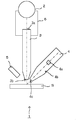
図1は本発明の蛍光X線分析装置の概要を説明するための概略図である。
蛍光X線分析装置1は、一次X線を放出するX線管2と、X線管2からの一次X線の照射径を制限するコリメータ、又は一時X線を試料Sの表面に集光して照射するキャピラリレンズ(以下コリメータ部3とする)と、試料Sからの蛍光X線を検出する検出器4と、試料Sの光学像を観察するCCDカメラ等の光学観察手段5を備える。
【0020】
X線管2は、測定対象の元素の特性X線の発生に応じたエネルギーの一次X線を発生し、コリメータ部3を通して試料S上に照射する。
コリメータ部3は、X線管2側の端部及び試料S側の端部の両端を、X線透過性を有しかつ真空密閉可能な薄膜3a,3bで遮蔽する。薄膜3a,3bで遮蔽されたコリメータ部3の内部は、真空又はヘリウム雰囲気に保持する。コリメータ部3の内部の真空保持は、真空ポンプで吸引する構成の他、真空封じした構成によって行うことができる。薄膜3a,3bは、一次X線の吸収率が低く、膜自体の組成によって蛍光X線を発生しないと共に、大気圧程度の圧力に耐える強度を備える素材が望ましい。このような素材の薄膜として、例えばポリエステル樹脂膜が知られており、数μm程度の厚みとすることができる。
なお、図1では、コリメータ部3の内部を排気するための排気手段は省略している。
【0021】
一次X線は、X線管のターゲットとしてRhを使用した場合、エネルギーの高いRhのK線及び連続X線の他に、エネルギーが比較的低いRhのL線も発生する。RhのL線は、エネルギーが比較的低いため、大気中を通って試料に照射された場合には空気によって減衰され、十分な量の蛍光X線を得ることができない。これに対して、本発明の蛍光X線分析装置は、コリメータ部の両端をX線透過性を有しかつ真空密閉可能に遮蔽した構成とすることで、低エネルギーの一次X線であっても空気で減衰することなく試料に照射され、軽元素の蛍光X線の励起効率を高めることができるため、十分な量の蛍光X線を得ることができる。
【0022】
なお、コリメータ部3は、検出器4が検出する蛍光X線と干渉しない程度まで薄膜3bを試料S側に接近させる構成とすることによって、薄膜3bと試料Sとの間の距離を最小限に短くすることができるため、X線管2から放出された一次X線は空気による減衰をより抑えることができる。
【0023】
コリメータ部3によって試料S上の微小部分に照射された一次X線は、試料S中に含まれる測定対象の元素を励起し、元素に固有のエネルギーを有する特性X線を放出させる。一般に、測定対象の元素に固有の特性X線に対して、この特性X線のエネルギーよりもわずかに高いエネルギーを有する一次X線を照射することによって、蛍光X線の発生効率を高めることができる。
【0024】
検出器4は、試料Sから放出された蛍光X線を検出する。検出器4は、蛍光X線を検出する検出素子4aと、この検出素子4aを真空雰囲気に保持するチャンバー4bと、蛍光X線をチャンバー4b内に導入する検出窓4cとを備える。チャンバー4bは、一次X線と干渉しない程度まで先端部分を試料Sの方向に延ばし、検出窓4cを試料Sに接近した位置に配置する。検出窓4cを試料Sに接近した位置に配置することによって、試料Sから放出された蛍光X線は、短い空気の区間を通過した後、検出窓4cを通ってチャンバー4b内に導入される。チャンバー4b内は本来真空に排気されており、検出窓4cと検出素子4aとの間において空気による減衰はない。本発明の蛍光X線装置によれば、検出窓4cを試料Sに接近した位置に配置する構成とすることで、蛍光X線の空気による減衰を最小限に抑えることができる。
【0025】
また、コリメータ部3の薄膜3bを設けた先端部及びチャンバー4bの検出窓4cを設けた先端部は小径とすることによって、両先端部をより試料Sに接近させることができ、一次X線及び蛍光X線が大気に晒される区間を短くし、空気による減衰をより少なくすることができる。
【0026】
図2は本発明の蛍光X線分析装置の他の構成例を説明するための概略図である。図2に示す構成例は、X線管とコリメータ部との間を真空又はヘリウム雰囲気とする例であり、その他の構成は図1に示す構成例と同様である。そこで、以下では、図1に示す構成例と相違する点についてのみ説明し、その他の共通する構成について説明を省略する。
【0027】
図2において、少なくともX線管2のX線放射口とコリメータ部3のX線管2側の端部との間の空間を、気密のチャンバー6によって密閉空間とし、この内部を真空又はヘリウム雰囲気とする。この構成によれば、X線管2からコリメータ部3に達するまでの間において、一次X線の空気による減衰をさらに少なくすることができる。
【0028】
また、本発明の構成においても、検出窓及びコリメータ部に薄膜を設けており、この薄膜は蛍光X線や一次X線を減衰させる要因となるが、測定側と試料側との間を薄膜を張設した開口部を有する測定室で仕切る構成と比較したとき、蛍光X線については、従来の構成では開口部と検出窓の2つの箇所の薄膜を通過するのに対して、本発明の構成では検出窓の薄膜のみを通過するだけであるため、薄膜通過による影響を少なくすることができ、また、一次X線については、空気による減衰を抑制することで十分なエネルギーが薄膜部分を通過するため、薄膜通過による影響を相対的に小さくすることができる。
【0029】
さらに、検出窓及びコリメータ部の薄膜の面積を必要最小限に抑えることができるので、より薄い膜の使用が可能であり、X線の減衰を最小限にすることができる。
したがって、本発明の構成によれば、試料中の重元素だけでなく軽元素についても効率的に励起することができ、励起した低エネルギーの蛍光X線を効率的に検出することができ、Na,Mg,Alなど大気による吸収の大きい軽元素の蛍光X線のX線強度を安定かつ感度よく検出することができる。
【0030】
また、本発明の構成によれば、試料を光学的に観察する際、測定側を真空に保持する測定室に設けた開口部によって視野が制限されることがないため、光学観察手段5によって広い観察範囲を得ることができる。
【0031】
【発明の効果】
以上説明したように、本発明の蛍光X線分析装置によれば、低エネルギーのX線、特に軽元素の特性X線を高感度で検出することができる。
【図面の簡単な説明】
【図1】本発明の蛍光X線分析装置の概要を説明するための概略図である。
【図2】本発明の蛍光X線分析装置の他の構成例を説明するための概略図である。
【図3】従来の蛍光X線分析装置の概要を説明するための概略図である。
【符号の説明】
1…蛍光X線分析装置、2…X線管、3…コリメータ部、3a,3b…薄膜、4…検出器、4a…検出素子、4b…チャンバー、4c…検出窓、5…光学観察手段、6…チャンバー、S…試料。[0001]
BACKGROUND OF THE INVENTION
The present invention relates to an X-ray fluorescence analyzer used for analyzing the type, amount, and distribution state of elements contained in a sample.
[0002]
[Prior art]
The X-ray fluorescence analyzer irradiates a sample with primary X-rays, detects the X-ray fluorescence generated from the sample with an X-ray detector, and analyzes the constituent elements and internal structure of the sample based on this detection signal I do.
[0003]
In this fluorescent X-ray analyzer, the arrangement of the sample and the configuration in which the X-ray irradiation region for irradiating the arranged sample with the primary X-ray is set to atmospheric pressure, or by surrounding the X-ray irradiation region with a measurement chamber or the like There is known a configuration in which the atmosphere is cut off from the atmosphere and the inside of the measurement chamber is in a vacuum atmosphere or in a gas atmosphere (for example, helium gas) that absorbs primary X-rays and fluorescent X-rays less than the atmosphere.
[0004]
FIG. 3 is a schematic diagram for explaining a configuration example of a conventional fluorescent X-ray apparatus. FIG. 3A is a configuration example in which the sample and the X-ray irradiation region are at atmospheric pressure, and FIG. 3B is a configuration example in which the sample and the X-ray irradiation region are in a vacuum atmosphere or a gas atmosphere.
[0005]
In the configuration shown in FIG. 3A, an
[0006]
In the configuration shown in FIG. 3B, the collimator or
[0007]
When the fluorescent X-ray to be measured can ignore the absorption by air (for example, characteristic X-rays of heavy elements), as shown in FIG. 3A, the X-ray source side such as an X-ray tube or a collimator, a sample , And the detector side can be measured with the atmosphere kept at the same time. On the other hand, when the fluorescent X-rays to be measured cannot absorb the absorption by air (for example, characteristic X-rays of light elements having a large absorption by the atmosphere such as Na, Mg, Al), the inside of the X-ray tube and the detector is vacuum. However, since the other portions are exposed to the atmosphere, there is a problem that X-ray absorption increases and detection is difficult.
In the configuration shown in FIG. 3B, the entire X-ray path including the X-ray source, the sample, and the detector is made a vacuum atmosphere or a gas atmosphere, thereby preventing X-ray absorption by the air.
[0008]
In a configuration in which X-ray fluorescence analysis is performed in vacuum or helium gas, it is necessary to evacuate the measurement chamber or replace the gas every time the sample is replaced. Since it is necessary to return to the atmosphere later, there is a problem that the total analysis time becomes long and the working efficiency is poor. In addition, in the case of a sample containing a living body or moisture, there is also a problem that evacuation cannot be performed.
[0009]
An apparatus using a thin film (for example, Japanese Patent Laid-Open No. 8-15187) is known as an X-ray analysis apparatus considering the above problems. The configuration shown in FIG. 3C is a diagram showing a configuration example of an apparatus using a thin film. An opening 7 is provided in the
[0010]
However, in a device using a thin film, it is possible to measure even light elements that are strongly absorbed by the atmosphere. However, since both primary X-rays and fluorescent X-rays pass through the thin film provided in the opening, In addition to the attenuation of primary X-rays with low energy, there is a problem in that the X-ray intensity of fluorescent X-rays caused by light elements such as Na and Mg decreases due to attenuation of fluorescent X-rays. Further, there is a problem in that extra fluorescent X-rays and scattered X-rays are generated by the thin film, which adversely affects measurement data.
[0011]
Furthermore, since the thin film must withstand the pressure difference between atmospheric pressure and vacuum, it is necessary to reduce the aperture of the opening where the thin film is provided. Therefore, there is also a problem that the observation range becomes narrow when observing through the opening with the naked eye or with an optical microscope.
[0012]
[Problems to be solved by the invention]
Therefore, in the configuration in which the primary X-ray is irradiated in the atmosphere and the fluorescent X-ray from the sample is detected, there is a problem that the primary X-ray and the fluorescent X-ray are absorbed by the atmosphere, and the entire sample including the sample is evacuated. In this configuration, there is a problem that the working efficiency is poor and it cannot be applied to a sample containing moisture, and in the configuration in which a window is provided between the measurement unit and the sample and only the measurement unit is evacuated, it is used for the window. Fluorescent X-rays of trace elements contained in the material (polymer thin film) and scattered X-rays of primary X-rays may be detected, and the space and volume to be held in a vacuum are relatively large. However, there is a problem that an evacuation device such as a vacuum pump is necessary for evacuation.
[0013]
Accordingly, the present invention aims to solve the above-described conventional problems, prevent attenuation of low energy X-rays by the atmosphere, and particularly detect characteristic X-rays of light elements with high sensitivity. It is another object of the present invention to prevent attenuation of low energy primary X-rays by the atmosphere and / or attenuation of low energy fluorescent X-rays by the atmosphere.
[0014]
[Means for Solving the Problems]
The present invention detects an X-ray tube, a collimator that narrows the irradiation diameter of primary X-rays from the X-ray tube or a capillary lens that collects and irradiates primary X-rays on a sample surface, and fluorescent X-rays from the sample A detector and a first configuration that prevents attenuation of fluorescent X-rays by air and / or a second configuration that prevents attenuation of primary X-rays by air are provided.
[0015]
The first configuration is a configuration provided in the detector to prevent the fluorescent X-rays from being attenuated by air while the fluorescent X-rays travel from the sample to the detection element.
The detector includes a detection window for introducing fluorescent X-rays therein and a chamber for maintaining a vacuum state between the detection window and the detection element, and uses the detection window as a sample so as not to interfere with the primary X-rays. The chamber is configured to be placed in close proximity.
[0016]
With this first configuration, fluorescent X-rays are introduced into the detector chamber through the detection window immediately after emission from the sample. Since the space between the detection window and the detection element is in a vacuum state, fluorescent X-rays are detected by the detection element without being attenuated by air.
In addition, the detection window is a configuration that the detector originally includes, and since there is no thin film stretched between the sample and the detection element in the opening of the conventional apparatus, extra fluorescent X-rays or Scattered X-rays are not detected.
[0017]
In the second configuration, a collimator or a capillary lens is provided to prevent the fluorescent X-ray from being attenuated by air while the primary X-ray is directed from the X-ray source to the sample.
The collimator or capillary lens of the second configuration includes thin films provided at both ends of the X-ray source side and the sample side, both ends are shielded by a thin film having X-ray permeability and capable of being vacuum-sealed, and the inside is vacuumed Or it is set as the structure hold | maintained in a helium atmosphere.
[0018]
With this configuration, primary X-rays from the X-ray source are irradiated to a minute position on the sample by a collimator or a capillary lens. Since the inside of the collimator or capillary lens is in a vacuum state, even if it is a low-energy primary X-ray, the sample is irradiated without being attenuated by air, and the excitation efficiency of the light element fluorescent X-ray is increased.
Since the sealed part with the atmosphere on the X-ray irradiation side is only the both ends of the collimator or the capillary lens, it can maintain a vacuum hermetic for a long period of time, and a configuration such as a vacuum pump for evacuating is unnecessary. It can be.
[0019]
DETAILED DESCRIPTION OF THE INVENTION
Hereinafter, embodiments of the present invention will be described in detail with reference to the drawings.
FIG. 1 is a schematic view for explaining the outline of the fluorescent X-ray analyzer of the present invention.
The X-ray fluorescence analyzer 1 collects an
[0020]
The
The
In FIG. 1, exhaust means for exhausting the inside of the
[0021]
In the case where Rh is used as a target of the X-ray tube, primary X-rays generate Rh L rays having relatively low energy in addition to high-energy Rh K rays and continuous X-rays. Since the Rh L-ray has a relatively low energy, it is attenuated by air when irradiated through the atmosphere to the sample, and a sufficient amount of fluorescent X-rays cannot be obtained. On the other hand, the fluorescent X-ray analysis apparatus of the present invention has a configuration in which both ends of the collimator unit are shielded so as to have X-ray transparency and can be vacuum-sealed, so that even with low energy primary X-rays. Since the sample is irradiated with air without being attenuated and the excitation efficiency of the light element fluorescent X-rays can be increased, a sufficient amount of fluorescent X-rays can be obtained.
[0022]
In addition, the
[0023]
The primary X-ray irradiated to the minute part on the sample S by the
[0024]
The
[0025]
Further, by making the tip of the
[0026]
FIG. 2 is a schematic diagram for explaining another configuration example of the fluorescent X-ray analyzer of the present invention. The configuration example shown in FIG. 2 is an example in which the space between the X-ray tube and the collimator unit is a vacuum or helium atmosphere, and other configurations are the same as the configuration example shown in FIG. Therefore, hereinafter, only differences from the configuration example shown in FIG. 1 will be described, and description of other common configurations will be omitted.
[0027]
In FIG. 2, at least a space between the X-ray emission port of the
[0028]
Also in the configuration of the present invention, a thin film is provided in the detection window and the collimator unit, and this thin film causes attenuation of fluorescent X-rays and primary X-rays, but a thin film is provided between the measurement side and the sample side. Compared with the configuration of partitioning with a measurement chamber having a stretched opening, fluorescent X-rays pass through the thin film at two locations of the opening and the detection window in the conventional configuration, whereas the configuration of the present invention Since only the thin film of the detection window passes through, the influence of the thin film passing can be reduced, and sufficient energy passes through the thin film portion by suppressing attenuation by air for the primary X-ray. For this reason, the influence of passing through the thin film can be relatively reduced.
[0029]
Furthermore, since the area of the thin film of the detection window and collimator section can be minimized, a thinner film can be used, and attenuation of X-rays can be minimized.
Therefore, according to the configuration of the present invention, not only heavy elements but also light elements in the sample can be excited efficiently, and excited low energy fluorescent X-rays can be detected efficiently, and Na It is possible to detect the X-ray intensity of fluorescent X-rays of light elements that are highly absorbed by the atmosphere, such as Mg, Mg, Al, stably and with high sensitivity.
[0030]
Further, according to the configuration of the present invention, when the sample is optically observed, the field of view is not limited by the opening provided in the measurement chamber that holds the measurement side in a vacuum, so that the optical observation means 5 widens the field of view. An observation range can be obtained.
[0031]
【The invention's effect】
As described above, according to the fluorescent X-ray analysis apparatus of the present invention, low-energy X-rays, in particular, characteristic X-rays of light elements can be detected with high sensitivity.
[Brief description of the drawings]
FIG. 1 is a schematic view for explaining the outline of a fluorescent X-ray analysis apparatus of the present invention.
FIG. 2 is a schematic view for explaining another configuration example of the fluorescent X-ray analysis apparatus of the present invention.
FIG. 3 is a schematic diagram for explaining the outline of a conventional X-ray fluorescence analyzer.
[Explanation of symbols]
DESCRIPTION OF SYMBOLS 1 ... Fluorescence X-ray analyzer, 2 ... X-ray tube, 3 ... Collimator part, 3a, 3b ... Thin film, 4 ... Detector, 4a ... Detection element, 4b ... Chamber, 4c ... Detection window, 5 ... Optical observation means, 6 ... chamber, S ... sample.
Claims (1)
前記X線管からの一次X線を試料表面に照射するコリメータ又はキャピラリレンズと、
試料からの蛍光X線を検出する検出器と、
試料表面を観察する光学観察手段と、
前記蛍光X線の空気による減衰を防ぐ第1の構成、
前記一次X線の空気による減衰を防ぐ第2の構成を備え、
前記第1の構成は、前記検出器において、蛍光X線を内部に導入する検出窓と、当該検出窓と導入した蛍光X線を検出する検出素子との間を真空状態に保持するチャンバーとを備え、当該チャンバーは一次X線と干渉しない程度まで前記検出窓を試料に接近した位置に配置する構成であり、
前記第2の構成は、前記コリメータ又はキャピラリレンズにおいて、両端をX線透過性を有しかつ真空密閉可能な薄膜で遮蔽し、内部を真空又はヘリウム雰囲気に保持する構成であり、
前記第1、第2の構成によって前記光学観察手段の視野が制限されることなく、広い観察範囲が得られることを特徴とする蛍光X線分析装置。An X-ray tube;
A collimator or capillary lens that irradiates the sample surface with primary X-rays from the X-ray tube;
A detector for detecting fluorescent X-rays from the sample;
Optical observation means for observing the sample surface;
A first configuration for preventing the fluorescent X-ray from being attenuated by air;
A second configuration for preventing the primary X-ray from being attenuated by air;
In the first configuration, the detector includes a detection window for introducing fluorescent X-rays therein, and a chamber for maintaining a vacuum state between the detection window and a detection element for detecting the introduced fluorescent X-rays. And the chamber is configured to place the detection window at a position close to the sample to the extent that it does not interfere with primary X-rays.
The second configuration is a configuration in which, in the collimator or the capillary lens, both ends are shielded with a thin film having X-ray transparency and vacuum-sealing, and the inside is maintained in a vacuum or helium atmosphere.
A fluorescent X-ray analyzer characterized in that a wide observation range can be obtained without limiting the field of view of the optical observation means by the first and second configurations.
Priority Applications (2)
| Application Number | Priority Date | Filing Date | Title |
|---|---|---|---|
| JP2002007329A JP3724424B2 (en) | 2002-01-16 | 2002-01-16 | X-ray fluorescence analyzer |
| US10/317,185 US20030133536A1 (en) | 2002-01-16 | 2002-12-12 | X-ray fluorescence spectrometer |
Applications Claiming Priority (1)
| Application Number | Priority Date | Filing Date | Title |
|---|---|---|---|
| JP2002007329A JP3724424B2 (en) | 2002-01-16 | 2002-01-16 | X-ray fluorescence analyzer |
Publications (3)
| Publication Number | Publication Date |
|---|---|
| JP2003207466A JP2003207466A (en) | 2003-07-25 |
| JP2003207466A5 JP2003207466A5 (en) | 2005-04-07 |
| JP3724424B2 true JP3724424B2 (en) | 2005-12-07 |
Family
ID=19191319
Family Applications (1)
| Application Number | Title | Priority Date | Filing Date |
|---|---|---|---|
| JP2002007329A Expired - Lifetime JP3724424B2 (en) | 2002-01-16 | 2002-01-16 | X-ray fluorescence analyzer |
Country Status (2)
| Country | Link |
|---|---|
| US (1) | US20030133536A1 (en) |
| JP (1) | JP3724424B2 (en) |
Families Citing this family (9)
| Publication number | Priority date | Publication date | Assignee | Title |
|---|---|---|---|---|
| DE102004019030A1 (en) * | 2004-04-17 | 2005-11-03 | Katz, Elisabeth | Device for elemental analysis |
| JP5102549B2 (en) * | 2006-07-14 | 2012-12-19 | 独立行政法人科学技術振興機構 | X-ray analyzer and X-ray analysis method |
| JP2009210371A (en) * | 2008-03-04 | 2009-09-17 | Tohken Co Ltd | Low acceleration voltage x-ray microscope device |
| US7972062B2 (en) * | 2009-07-16 | 2011-07-05 | Edax, Inc. | Optical positioner design in X-ray analyzer for coaxial micro-viewing and analysis |
| CN102543243B (en) | 2010-12-28 | 2016-07-13 | Ge医疗系统环球技术有限公司 | Integrated capillary type parallel X-ray focusing lens |
| ES2795988T3 (en) * | 2013-05-27 | 2020-11-25 | Shimadzu Corp | X-ray fluorescence analyzer |
| CN103698350B (en) * | 2013-12-26 | 2016-03-30 | 北京师范大学 | A kind of X-ray double spectrometer |
| US10175184B2 (en) | 2015-06-22 | 2019-01-08 | Moxtek, Inc. | XRF analyzer for light element detection |
| JP7361389B2 (en) | 2020-03-04 | 2023-10-16 | 国立研究開発法人産業技術総合研究所 | Optical and synchrotron radiation microspectroscopy equipment |
Family Cites Families (3)
| Publication number | Priority date | Publication date | Assignee | Title |
|---|---|---|---|---|
| JPH082604Y2 (en) * | 1989-08-03 | 1996-01-29 | 理学電機工業株式会社 | Characteristic X-ray detector |
| US5192869A (en) * | 1990-10-31 | 1993-03-09 | X-Ray Optical Systems, Inc. | Device for controlling beams of particles, X-ray and gamma quanta |
| US6345086B1 (en) * | 1999-09-14 | 2002-02-05 | Veeco Instruments Inc. | X-ray fluorescence system and method |
-
2002
- 2002-01-16 JP JP2002007329A patent/JP3724424B2/en not_active Expired - Lifetime
- 2002-12-12 US US10/317,185 patent/US20030133536A1/en not_active Abandoned
Also Published As
| Publication number | Publication date |
|---|---|
| JP2003207466A (en) | 2003-07-25 |
| US20030133536A1 (en) | 2003-07-17 |
Similar Documents
| Publication | Publication Date | Title |
|---|---|---|
| US5740223A (en) | Fluorescent X-ray analyzer with sealed X-ray shield wall | |
| KR101752164B1 (en) | Charged particle beam apparatus and sample image acquiring method | |
| KR101671323B1 (en) | Charged particle beam device and sample observation method | |
| JP3724424B2 (en) | X-ray fluorescence analyzer | |
| RU2576550C2 (en) | Leak detector with optical detection of test gas | |
| JP2001133421A (en) | X-ray spectrometer and x-ray diffractometer | |
| JP3718818B2 (en) | Cathodoluminescence sample holder and cathodoluminescence spectrometer | |
| JP2011203102A (en) | Sample holder and sample analysis method | |
| JP2003207466A5 (en) | ||
| JP3981976B2 (en) | X-ray analysis method | |
| KR102029869B1 (en) | Detachable Sample Chamber for Electron Microscope and Electron Microscope Comprising The Same | |
| JP2002528859A (en) | X-ray irradiator having X source including capillary optics | |
| JP6352616B2 (en) | X-ray measuring device | |
| JP3599259B2 (en) | X-ray analyzer | |
| JP3771697B2 (en) | Fluorescent X-ray analyzer | |
| JP2002303593A (en) | X-ray analyzer | |
| WO2015022725A1 (en) | X-ray detection device | |
| JPH0815187A (en) | Fluorescent x-ray analyzer | |
| WO2022264809A1 (en) | Immunochromatographic test strip testing device and testing method, and test system | |
| JP2000329713A (en) | X-ray analyzer | |
| JP2991253B2 (en) | X-ray fluorescence spectroscopy method and apparatus | |
| WO2021112079A1 (en) | X-ray fluorescence analysis device | |
| JP7386259B2 (en) | Fluorescent X-ray analyzer | |
| JP2008123782A (en) | X-ray source | |
| JPH03216581A (en) | X-ray counter |
Legal Events
| Date | Code | Title | Description |
|---|---|---|---|
| A521 | Request for written amendment filed |
Free format text: JAPANESE INTERMEDIATE CODE: A523 Effective date: 20040601 |
|
| A621 | Written request for application examination |
Free format text: JAPANESE INTERMEDIATE CODE: A621 Effective date: 20040601 |
|
| A977 | Report on retrieval |
Free format text: JAPANESE INTERMEDIATE CODE: A971007 Effective date: 20050222 |
|
| A131 | Notification of reasons for refusal |
Free format text: JAPANESE INTERMEDIATE CODE: A131 Effective date: 20050228 |
|
| A521 | Request for written amendment filed |
Free format text: JAPANESE INTERMEDIATE CODE: A523 Effective date: 20050408 |
|
| TRDD | Decision of grant or rejection written | ||
| A01 | Written decision to grant a patent or to grant a registration (utility model) |
Free format text: JAPANESE INTERMEDIATE CODE: A01 Effective date: 20050830 |
|
| A61 | First payment of annual fees (during grant procedure) |
Free format text: JAPANESE INTERMEDIATE CODE: A61 Effective date: 20050912 |
|
| R150 | Certificate of patent or registration of utility model |
Ref document number: 3724424 Country of ref document: JP Free format text: JAPANESE INTERMEDIATE CODE: R150 Free format text: JAPANESE INTERMEDIATE CODE: R150 |
|
| FPAY | Renewal fee payment (event date is renewal date of database) |
Free format text: PAYMENT UNTIL: 20080930 Year of fee payment: 3 |
|
| FPAY | Renewal fee payment (event date is renewal date of database) |
Free format text: PAYMENT UNTIL: 20090930 Year of fee payment: 4 |
|
| FPAY | Renewal fee payment (event date is renewal date of database) |
Free format text: PAYMENT UNTIL: 20090930 Year of fee payment: 4 |
|
| FPAY | Renewal fee payment (event date is renewal date of database) |
Free format text: PAYMENT UNTIL: 20100930 Year of fee payment: 5 |
|
| FPAY | Renewal fee payment (event date is renewal date of database) |
Free format text: PAYMENT UNTIL: 20110930 Year of fee payment: 6 |
|
| FPAY | Renewal fee payment (event date is renewal date of database) |
Free format text: PAYMENT UNTIL: 20110930 Year of fee payment: 6 |
|
| FPAY | Renewal fee payment (event date is renewal date of database) |
Free format text: PAYMENT UNTIL: 20120930 Year of fee payment: 7 |
|
| FPAY | Renewal fee payment (event date is renewal date of database) |
Free format text: PAYMENT UNTIL: 20120930 Year of fee payment: 7 |
|
| FPAY | Renewal fee payment (event date is renewal date of database) |
Free format text: PAYMENT UNTIL: 20130930 Year of fee payment: 8 |
|
| EXPY | Cancellation because of completion of term |