WO2022264740A1 - 制御装置、制御方法、制御プログラム - Google Patents
制御装置、制御方法、制御プログラム Download PDFInfo
- Publication number
- WO2022264740A1 WO2022264740A1 PCT/JP2022/020647 JP2022020647W WO2022264740A1 WO 2022264740 A1 WO2022264740 A1 WO 2022264740A1 JP 2022020647 W JP2022020647 W JP 2022020647W WO 2022264740 A1 WO2022264740 A1 WO 2022264740A1
- Authority
- WO
- WIPO (PCT)
- Prior art keywords
- interference
- host vehicle
- control
- vehicle
- risk
- Prior art date
Links
- 238000000034 method Methods 0.000 title claims description 13
- 238000012954 risk control Methods 0.000 claims abstract description 54
- 230000000116 mitigating effect Effects 0.000 claims abstract description 18
- 230000008859 change Effects 0.000 claims description 75
- 238000005286 illumination Methods 0.000 claims description 7
- 230000003449 preventive effect Effects 0.000 claims 1
- 238000004891 communication Methods 0.000 description 45
- 238000010586 diagram Methods 0.000 description 12
- 230000004044 response Effects 0.000 description 10
- 230000007704 transition Effects 0.000 description 8
- 230000002265 prevention Effects 0.000 description 6
- 230000002452 interceptive effect Effects 0.000 description 5
- 239000004065 semiconductor Substances 0.000 description 5
- 238000001514 detection method Methods 0.000 description 4
- 230000001133 acceleration Effects 0.000 description 3
- 238000005259 measurement Methods 0.000 description 3
- 230000003287 optical effect Effects 0.000 description 3
- 230000009471 action Effects 0.000 description 2
- 230000000694 effects Effects 0.000 description 2
- 230000004048 modification Effects 0.000 description 2
- 238000012986 modification Methods 0.000 description 2
- 230000008569 process Effects 0.000 description 2
- 238000012545 processing Methods 0.000 description 2
- 238000013349 risk mitigation Methods 0.000 description 2
- 230000001413 cellular effect Effects 0.000 description 1
- 230000003247 decreasing effect Effects 0.000 description 1
- 238000005516 engineering process Methods 0.000 description 1
- 230000006870 function Effects 0.000 description 1
- 238000003384 imaging method Methods 0.000 description 1
- 230000001360 synchronised effect Effects 0.000 description 1
Images


Classifications
-
- B—PERFORMING OPERATIONS; TRANSPORTING
- B60—VEHICLES IN GENERAL
- B60W—CONJOINT CONTROL OF VEHICLE SUB-UNITS OF DIFFERENT TYPE OR DIFFERENT FUNCTION; CONTROL SYSTEMS SPECIALLY ADAPTED FOR HYBRID VEHICLES; ROAD VEHICLE DRIVE CONTROL SYSTEMS FOR PURPOSES NOT RELATED TO THE CONTROL OF A PARTICULAR SUB-UNIT
- B60W30/00—Purposes of road vehicle drive control systems not related to the control of a particular sub-unit, e.g. of systems using conjoint control of vehicle sub-units
- B60W30/14—Adaptive cruise control
- B60W30/143—Speed control
-
- G—PHYSICS
- G08—SIGNALLING
- G08G—TRAFFIC CONTROL SYSTEMS
- G08G1/00—Traffic control systems for road vehicles
- G08G1/16—Anti-collision systems
-
- B—PERFORMING OPERATIONS; TRANSPORTING
- B60—VEHICLES IN GENERAL
- B60Q—ARRANGEMENT OF SIGNALLING OR LIGHTING DEVICES, THE MOUNTING OR SUPPORTING THEREOF OR CIRCUITS THEREFOR, FOR VEHICLES IN GENERAL
- B60Q1/00—Arrangement of optical signalling or lighting devices, the mounting or supporting thereof or circuits therefor
- B60Q1/02—Arrangement of optical signalling or lighting devices, the mounting or supporting thereof or circuits therefor the devices being primarily intended to illuminate the way ahead or to illuminate other areas of way or environments
- B60Q1/04—Arrangement of optical signalling or lighting devices, the mounting or supporting thereof or circuits therefor the devices being primarily intended to illuminate the way ahead or to illuminate other areas of way or environments the devices being headlights
- B60Q1/06—Arrangement of optical signalling or lighting devices, the mounting or supporting thereof or circuits therefor the devices being primarily intended to illuminate the way ahead or to illuminate other areas of way or environments the devices being headlights adjustable, e.g. remotely-controlled from inside vehicle
- B60Q1/08—Arrangement of optical signalling or lighting devices, the mounting or supporting thereof or circuits therefor the devices being primarily intended to illuminate the way ahead or to illuminate other areas of way or environments the devices being headlights adjustable, e.g. remotely-controlled from inside vehicle automatically
- B60Q1/085—Arrangement of optical signalling or lighting devices, the mounting or supporting thereof or circuits therefor the devices being primarily intended to illuminate the way ahead or to illuminate other areas of way or environments the devices being headlights adjustable, e.g. remotely-controlled from inside vehicle automatically due to special conditions, e.g. adverse weather, type of road, badly illuminated road signs or potential dangers
-
- B—PERFORMING OPERATIONS; TRANSPORTING
- B60—VEHICLES IN GENERAL
- B60W—CONJOINT CONTROL OF VEHICLE SUB-UNITS OF DIFFERENT TYPE OR DIFFERENT FUNCTION; CONTROL SYSTEMS SPECIALLY ADAPTED FOR HYBRID VEHICLES; ROAD VEHICLE DRIVE CONTROL SYSTEMS FOR PURPOSES NOT RELATED TO THE CONTROL OF A PARTICULAR SUB-UNIT
- B60W60/00—Drive control systems specially adapted for autonomous road vehicles
- B60W60/001—Planning or execution of driving tasks
- B60W60/0027—Planning or execution of driving tasks using trajectory prediction for other traffic participants
-
- G—PHYSICS
- G01—MEASURING; TESTING
- G01S—RADIO DIRECTION-FINDING; RADIO NAVIGATION; DETERMINING DISTANCE OR VELOCITY BY USE OF RADIO WAVES; LOCATING OR PRESENCE-DETECTING BY USE OF THE REFLECTION OR RERADIATION OF RADIO WAVES; ANALOGOUS ARRANGEMENTS USING OTHER WAVES
- G01S13/00—Systems using the reflection or reradiation of radio waves, e.g. radar systems; Analogous systems using reflection or reradiation of waves whose nature or wavelength is irrelevant or unspecified
- G01S13/88—Radar or analogous systems specially adapted for specific applications
- G01S13/93—Radar or analogous systems specially adapted for specific applications for anti-collision purposes
- G01S13/931—Radar or analogous systems specially adapted for specific applications for anti-collision purposes of land vehicles
-
- G—PHYSICS
- G01—MEASURING; TESTING
- G01S—RADIO DIRECTION-FINDING; RADIO NAVIGATION; DETERMINING DISTANCE OR VELOCITY BY USE OF RADIO WAVES; LOCATING OR PRESENCE-DETECTING BY USE OF THE REFLECTION OR RERADIATION OF RADIO WAVES; ANALOGOUS ARRANGEMENTS USING OTHER WAVES
- G01S17/00—Systems using the reflection or reradiation of electromagnetic waves other than radio waves, e.g. lidar systems
- G01S17/88—Lidar systems specially adapted for specific applications
- G01S17/93—Lidar systems specially adapted for specific applications for anti-collision purposes
- G01S17/931—Lidar systems specially adapted for specific applications for anti-collision purposes of land vehicles
-
- G—PHYSICS
- G01—MEASURING; TESTING
- G01S—RADIO DIRECTION-FINDING; RADIO NAVIGATION; DETERMINING DISTANCE OR VELOCITY BY USE OF RADIO WAVES; LOCATING OR PRESENCE-DETECTING BY USE OF THE REFLECTION OR RERADIATION OF RADIO WAVES; ANALOGOUS ARRANGEMENTS USING OTHER WAVES
- G01S7/00—Details of systems according to groups G01S13/00, G01S15/00, G01S17/00
- G01S7/02—Details of systems according to groups G01S13/00, G01S15/00, G01S17/00 of systems according to group G01S13/00
- G01S7/36—Means for anti-jamming, e.g. ECCM, i.e. electronic counter-counter measures
-
- B—PERFORMING OPERATIONS; TRANSPORTING
- B60—VEHICLES IN GENERAL
- B60Q—ARRANGEMENT OF SIGNALLING OR LIGHTING DEVICES, THE MOUNTING OR SUPPORTING THEREOF OR CIRCUITS THEREFOR, FOR VEHICLES IN GENERAL
- B60Q2300/00—Indexing codes for automatically adjustable headlamps or automatically dimmable headlamps
- B60Q2300/30—Indexing codes relating to the vehicle environment
- B60Q2300/33—Driving situation
-
- B—PERFORMING OPERATIONS; TRANSPORTING
- B60—VEHICLES IN GENERAL
- B60W—CONJOINT CONTROL OF VEHICLE SUB-UNITS OF DIFFERENT TYPE OR DIFFERENT FUNCTION; CONTROL SYSTEMS SPECIALLY ADAPTED FOR HYBRID VEHICLES; ROAD VEHICLE DRIVE CONTROL SYSTEMS FOR PURPOSES NOT RELATED TO THE CONTROL OF A PARTICULAR SUB-UNIT
- B60W2556/00—Input parameters relating to data
- B60W2556/45—External transmission of data to or from the vehicle
- B60W2556/65—Data transmitted between vehicles
-
- B—PERFORMING OPERATIONS; TRANSPORTING
- B60—VEHICLES IN GENERAL
- B60W—CONJOINT CONTROL OF VEHICLE SUB-UNITS OF DIFFERENT TYPE OR DIFFERENT FUNCTION; CONTROL SYSTEMS SPECIALLY ADAPTED FOR HYBRID VEHICLES; ROAD VEHICLE DRIVE CONTROL SYSTEMS FOR PURPOSES NOT RELATED TO THE CONTROL OF A PARTICULAR SUB-UNIT
- B60W2756/00—Output or target parameters relating to data
- B60W2756/10—Involving external transmission of data to or from the vehicle
Definitions
- the present disclosure relates to control techniques for preventing beam interference in a host vehicle's beam sensor with a target vehicle's beam sensor.
- Patent Document 1 reduces beam interference with the beam sensor mounted on the target vehicle by forming a predetermined pattern in the measurement light irradiation, which is the beam irradiation for distance measurement, in the beam sensor of the host vehicle. I am proposing to do so.
- Patent Document 1 the technique disclosed in Patent Document 1 is based on the premise that the beam sensor of the target vehicle also forms a predetermined pattern in the measurement light irradiation. Therefore, beam sensors have low versatility in the automobile society where various specifications exist, and it has been difficult to prevent interference noise caused by beam interference from affecting the sensing accuracy of the host vehicle.
- An object of the present disclosure is to provide a control device that ensures sensing accuracy. Another object of the present disclosure is to provide a control method that ensures sensing accuracy. Yet another object of the present disclosure is to provide a control program that ensures sensing accuracy.
- a first aspect of the present disclosure is A controller, having a processor, for preventing beam interference in a host vehicle beam sensor with a target vehicle beam sensor, comprising: The processor obtaining irradiation-related information related to beam irradiation of the host vehicle and the target vehicle; Predicting an interference scene in which beam interference occurs between a host vehicle and a target vehicle based on irradiation-related information; providing the host vehicle with interference risk control that mitigates the risk of beam interference in predicted interference scenes.
- a second aspect of the present disclosure is A control method executed by a processor for preventing beam interference in a host vehicle beam sensor with a target vehicle beam sensor, comprising: obtaining irradiation-related information related to beam irradiation of the host vehicle and the target vehicle; Predicting an interference scene in which beam interference occurs between a host vehicle and a target vehicle based on illumination-related information; providing the host vehicle with preventative interference risk control that mitigates the risk of beam interference in the predicted interference scene.
- a third aspect of the present disclosure is A control program stored in a storage medium and comprising instructions for execution by a processor for preventing beam interference in a beam sensor of a host vehicle with a beam sensor of a target vehicle, the control program comprising: the instruction is obtaining irradiation-related information related to beam irradiation of the host vehicle and the target vehicle; Predicting an interference scene in which beam interference occurs between a host vehicle and a target vehicle based on irradiation-related information; and causing the host vehicle to provide interference risk control that mitigates the risk of beam interference in predicted interference scenes.
- an interference scene in which beam interference occurs between the host vehicle and the target vehicle is predicted based on irradiation-related information related to beam irradiation of those vehicles.
- the host vehicle is given interference risk control that mitigates the risk of beam interference. Interference can be universally prevented. Therefore, it is possible to ensure sensing accuracy in the host vehicle.
- FIG. 2 is a schematic diagram showing a running environment of a host vehicle to which the first embodiment is applied; It is a block diagram which shows the functional structure of the control apparatus by 1st embodiment.
- 4 is a flow chart showing a control method according to the first embodiment;
- FIG. 4 is a schematic diagram for explaining an interference scene according to the first embodiment;
- FIG. 4 is a schematic diagram for explaining an interference scene according to the first embodiment;
- FIG. 4 is a schematic diagram for explaining an interference scene according to the first embodiment;
- 4 is a flow chart showing an interference risk control routine according to the first embodiment;
- FIG. 4 is a schematic diagram for explaining path change control according to the first embodiment;
- FIG. 4 is a schematic diagram for explaining path change control according to the first embodiment;
- FIG. 4 is a schematic diagram for explaining beam change control according to the first embodiment;
- FIG. 4 is a schematic diagram for explaining beam change control according to the first embodiment;
- FIG. 4 is a schematic diagram for explaining speed change control according to the first embodiment;
- It is a block diagram which shows the whole structure of 2nd embodiment. It is a block diagram which shows the functional structure of the control apparatus by 2nd embodiment.
- 6 is a flow chart showing a control method according to a second embodiment; 9 is a flow chart showing an interference risk control routine according to the second embodiment;
- the control device 1 of the first embodiment shown in FIG. 1 is a device for preventing beam interference with the beam sensor 30 of the target vehicle 3 shown in FIG. is. From a viewpoint centering on the host vehicle 2, the host vehicle 2 can be said to be an ego-vehicle. From a viewpoint centering on the host vehicle 2, the target vehicle 3 can also be said to be a user on another road.
- the host vehicle 2 may be given an automatic driving mode that is classified according to the degree of manual intervention of the driver in the driving task.
- Autonomous driving modes may be achieved by autonomous cruise control, such as conditional driving automation, advanced driving automation, or full driving automation, in which the system performs all driving tasks when activated.
- Autonomous driving modes may be provided by advanced driving assistance controls, such as driving assistance or partial driving automation, in which the occupant performs some or all driving tasks.
- the automatic driving mode may be realized by either one, combination, or switching of the autonomous driving control and advanced driving support control.
- the host vehicle 2 of the first embodiment is equipped with a control device 1 as well as a sensor system 4, a communication system 5, and a map database 7.
- the sensor system 4 acquires sensor information that can be used by the control device 1 by detecting the external and internal worlds of the host vehicle 2 . Therefore, the sensor system 4 includes an external sensor 40 and an internal sensor 41 .
- the external sensor 40 acquires external world information as sensor information from the external world that is the surrounding environment of the host vehicle 2 .
- the external world sensor 40 may acquire external world information by detecting targets existing in the external world of the host vehicle 2 .
- the target detection type external sensor 40 is, for example, at least one type of camera, LiDAR (Light Detection and Ranging/Laser Imaging Detection and Ranging), radar, sonar, and the like.
- At least one beam sensor 20 is mounted on the host vehicle 2 as such an external sensor 40 .
- the beam sensor 20 emits a beam toward the outside world of the host vehicle 2 and senses the reflected beam from the outside world to detect a target.
- the beam sensor 20 may be a LiDAR that emits laser light as a beam.
- the beam sensor 20 may be a millimeter wave radar that emits millimeter waves as a beam.
- an external sensor 40 having the same beam type as the beam sensor 20 of the host vehicle 2 is targeted for beam interference prevention.
- the beam sensor 30 that uses laser light as its beam is targeted for beam interference prevention in the host vehicle 2 .
- the beam sensor 30 that uses millimeter waves as its beam is targeted for beam interference prevention in the host vehicle 2 .
- the specifications of the beam sensors 20 and 30, including beam characteristics may be different or the same.
- the inner world sensor 41 shown in FIG. 1 acquires inner world information as sensor information from the inner world, which is the internal environment of the host vehicle 2 .
- the inner world sensor 41 may acquire inner world information by detecting a specific kinematic physical quantity in the inner world of the host vehicle 2 .
- the physical quantity sensing type internal sensor 41 is at least one of, for example, a running speed sensor, an acceleration sensor, a gyro sensor, and the like.
- the inner world sensor 41 may acquire inner world information by detecting a specific state of the occupant in the inner world of the host vehicle 2 .
- the occupant detection type internal sensor 41 is at least one of, for example, a driver status monitor (registered trademark), a biosensor, a seating sensor, an actuator sensor, an in-vehicle device sensor, and the like.
- the communication system 5 acquires communication information that can be used by the control device 1 through wireless communication.
- the communication system 5 includes a V2X type that transmits and receives communication signals to and from a V2X system that exists outside the host vehicle 2 .
- the V2X type communication system 5 is, for example, at least one of a DSRC (Dedicated Short Range Communications) communication device, a cellular V2X (C-V2X) communication device, and the like.
- the V2X type communication system 5 constructs a communication network capable of communicating between at least one target vehicle 3 and one remote center 6 outside the host vehicle 2 .
- the target vehicle 3 is equipped with a communication system and a map database in accordance with the host vehicle 2.
- the remote center 6 is mainly composed of server units such as cloud servers and edge servers (including infrastructure computers), communication units, and a map database.
- the remote center 6 is at least one of a management center that monitors and manages the operation of the host vehicle 2 and a service center that provides services related to the host vehicle 2 .
- power control processes may be performed in relation to road users, including the host vehicle 2, with whom communication is possible through the communication unit, such as for example displaying information to an operator of the remote center 6.
- the remote center 6 may perform an input control process such as receiving information to be fed back to the communicable road user from the operator of the remote center 6, for example.
- the communication system 5 may include a positioning type that receives positioning signals from artificial satellites of the GNSS (Global Navigation Satellite System) that exist outside the host vehicle 2 .
- the positioning type communication system 5 is, for example, a GNSS receiver or the like.
- the communication system 5 may include a terminal communication type that transmits and receives communication signals to and from a terminal existing inside the host vehicle 2 .
- the terminal communication type communication system 5 is, for example, at least one of Bluetooth (registered trademark) equipment, Wi-Fi (registered trademark) equipment, infrared communication equipment, and the like.
- the map database 7 stores map information that can be used by the control device 1.
- the map database 7 includes at least one type of non-transitory tangible storage medium, such as semiconductor memory, magnetic medium, and optical medium.
- the map database 7 may be a database of locators that estimate the state of motion, including the position of the host vehicle 2 .
- the map database 7 may be the database of a navigation unit that navigates the travel route of the host vehicle 2 .
- the map database 7 may be configured by combining a plurality of types of these databases.
- the map database 7 acquires and stores the latest map information through communication with the remote center 6 through the V2X type communication system 5.
- the map information is two-dimensional or three-dimensional data as information representing the running environment of the host vehicle 2 .
- the three-dimensional map data digital data of a high-precision map should be adopted.
- the map information may include road information representing at least one of the position, shape, road surface condition, and the like of the road itself.
- the map information may include sign information representing at least one of the position and shape of signs attached to roads and lane markings, for example.
- the map information may include structure information representing at least one of the positions and shapes of buildings facing roads and traffic lights, for example.
- the control device 1 is connected to the sensor system 4, the communication system 5, and the map database 7 via at least one of a LAN (Local Area Network) line, a wire harness, an internal bus, a wireless communication line, and the like. there is
- the control device 1 includes at least one dedicated computer.
- the dedicated computer that constitutes the control device 1 may be an operation control ECU (Electronic Control Unit) that controls the operation of the host vehicle 2 .
- a dedicated computer that configures the control device 1 may be a navigation ECU that navigates the travel route of the host vehicle 2 .
- a dedicated computer that constitutes the control device 1 may be a locator ECU that estimates the self-state quantity of the host vehicle 2 .
- the dedicated computer that constitutes the control device 1 may be an actuator ECU that controls the travel actuators of the host vehicle 2 .
- the dedicated computer that constitutes the control device 1 may be an HCU (HMI (Human Machine Interface) Control Unit) that controls information presentation in the host vehicle 2 .
- HCU Human Machine Interface
- the dedicated computer that constitutes the control device 1 has at least one memory 10 and at least one processor 12 .
- the memory 10 stores computer-readable programs and data non-temporarily, for example, at least one type of non-transitory physical storage medium (non-transitory storage medium) among semiconductor memory, magnetic medium, optical medium, etc. tangible storage medium).
- the processor 12 is, for example, CPU (Central Processing Unit), GPU (Graphics Processing Unit), RISC (Reduced Instruction Set Computer)-CPU, DFP (Data Flow Processor), GSP (Graph Streaming Processor), etc. At least one type as a core.
- a processor 12 in the controller 1 executes a plurality of instructions contained in a control program stored in the memory 10 to prevent beam interference in the beam sensor 20 of the host vehicle 2 with the beam sensor 30 of the target vehicle 3. .
- the control device 1 constructs a plurality of functional blocks in order to prevent the beam sensor 20 of the host vehicle 2 from interfering with the beam sensor 30 of the target vehicle 3 .
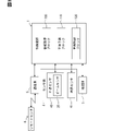
- Functional blocks constructed in the control device 1 include an information acquisition block 100, an interference prediction block 110, and a vehicle control block 120, as shown in FIG.
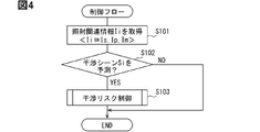
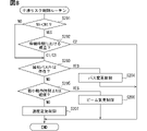
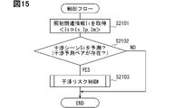
- the control method for the control device 1 to prevent the beam sensor 20 of the host vehicle 2 from interfering with the beam sensor 30 of the target vehicle 3 by combining these blocks 100, 110, and 120 follows the control flow shown in FIG. executed. This control flow is repeatedly executed while the host vehicle 2 is running. Each "S" in the control flow means a plurality of steps executed by a plurality of instructions included in the control program.
- the information acquisition block 100 acquires irradiation-related information Ii related to beam irradiation in each of the host vehicle 2 and the target vehicle 3.
- the irradiation-related information Ii of the host vehicle 2 is obtained through at least one of the sensor system 4 including the beam sensor 20, the communication system 5, and the map database 7.
- the irradiation-related information Ii of the target vehicle 3 is acquired through the communication system of the target vehicle 3 .
- the irradiation-related information Ii of each vehicle 2, 3 acquired by the information acquisition block 100 in S101 includes characteristic information Is of the beam sensors 20, 30, respectively.
- the characteristic information Is of each of the beam sensors 20 and 30 includes, for example, a sensing distance, a planned pattern of beam irradiation in which the irradiation timing is intermittent and the irradiation direction is scanned, and a minimum operation time ⁇ t required to change the planned pattern (Fig. 10 and 11), etc.) are shown.
- the planned pattern of beam irradiation here means a pattern representing the time transition of intermittent timing of beam irradiation and irradiation direction from the present to the future.
- the minimum operation time ⁇ t is the time from the start of beam change control (detailed later) for changing the planned pattern to the time the beam sensors 20 and 30 start changing the operation, or It is defined as the time required for the sensors 20, 30 to stabilize.
- the irradiation-related information Ii of each vehicle 2, 3 acquired by the information acquisition block 100 in S101 includes path information Ip.
- the path information Ip of each vehicle 2, 3 includes, for example, a planned future path Pf (see FIG. 9 described later), a velocity profile and an acceleration profile on the future path Pf, and an arrival time to a key point on the future path.
- Each of the plurality of types of path planning data including .
- the future path Pf means a planned course of the host vehicle 2, and particularly in the first embodiment, includes at least one of a route and a trajectory planned from the present to the future.
- the irradiation-related information Ii acquired by the information acquisition block 100 in S101 includes at least the map information Im stored in the map database 7 of the host vehicle 2 and the target vehicle 3 .
- the map information Im is acquired so as to associate the position of each control timing (that is, control time) from the present to the future with the characteristic information Is and the path information Ip of each vehicle 2 and 3 .
- the interference prediction block 110 calculates an interference scene Si in which beam interference occurs between the host vehicle 2 and the target vehicle 3 as shown in FIGS. Prediction is made based on the related information Ii.
- the interference scene Si is such that the distance between the vehicles 2 and 3 on the future path Pf of each vehicle 2 and 3 is equal to or less than the sum of the sensing distances of the beam sensors 20 and 30, and the beam sensors 20 and 30
- a future scene is defined in which the irradiation azimuths are crossed or opposite directions at the same time.
- the start time Ti of the scene Si see FIGS. 10 and 11 described later
- the time transition of the scene Si are estimated.
- FIG. 5 and FIGS. 9, 10, and 12, which will be described later, show the interference scene Si when the host vehicle 2 and the target vehicle 3 travel in opposing lanes with opposite directions of travel.
- FIG. 6 shows an interference scene Si when the host vehicle 2 and the target vehicle 3 travel in parallel lanes with the same direction of travel.
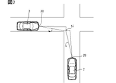
- FIG. 7 and FIG. 11, which will be described later, show an interference scene Si when the host vehicle 2 and the target vehicle 3 travel in cross lanes in which their traveling directions intersect each other.
- the vehicle control block 120 provides the host vehicle 2 with interference risk control that mitigates the risk of beam interference in the interference scene Si predicted by the interference prediction block 110 in S102. Therefore, the vehicle control block 120 in S103 executes an interference risk control routine as shown in FIG.
- the vehicle control block 120 changes the number of change paths Nh that can change the future path Pf currently selected by the host vehicle 2 and the future path Pf currently selected by the target vehicle 3. Contrast with the number of possible change paths Nt.
- the changed pass numbers Nh and Nt are recognized based on the irradiation-related information Ii acquired by the information acquisition block 100 in S101.
- the interference risk control routine proceeds to S202.
- the vehicle control block 120 maintains the control of the host vehicle 2 according to the future path Pf during the waiting time for waiting for the notification of the response from the target vehicle 3 through the communication system 5 .
- the interference risk control routine proceeds to S203.
- the vehicle control block 120 selects the optimal mitigation path for mitigating the risk of beam interference as a change controllable change path from the current future path Pf of the host vehicle 2 as shown in FIG. Determine if Pr exists.
- whether or not the modified path is optimal for risk mitigation is determined according to whether or not the prediction of the interference scene Si according to the interference prediction block 110 is resolved by the modified path.
- the interference risk control routine proceeds to S204 as shown in FIG.
- the vehicle control block 120 provides the host vehicle 2 with path change control (see FIG. 9) for changing the future path Pf to the relaxed path Pr. That is, the vehicle control block 120 in S204 performs path change control on the host vehicle 2 to cancel the prediction of the interference scene Si.
- the vehicle control block 120 may transmit a response notification indicating execution of path change control to the target vehicle 3 through the communication system 5 .
- the current execution of the interference risk control routine and control flow ends.
- the interference risk control routine proceeds to S205.
- the vehicle control block 120 may transmit a response notification indicating prohibition of path change control to the target vehicle 3 through the communication system 5 .
- the vehicle control block 120 ensures that the host vehicle 2 has a minimum operation time ⁇ t required to change the current planned pattern of beam irradiation to the optimal mitigation pattern for mitigating the risk of beam interference. Determine whether it is possible.
- the minimum operating time ⁇ t shown in FIGS. 10 and 11 is included in the pass information Ip among the irradiation-related information Ii acquired by the information acquisition block 100 in S101. Therefore, depending on whether the length of time from the start time Ti of the interference scene Si predicted by the interference prediction block 110 in S102 to the current time is greater than or equal to the length of the minimum action time ⁇ t, the minimum action time It is determined whether or not ⁇ t can be secured.
- the interference risk control routine proceeds to S206 as shown in FIG.
- the vehicle control block 120 provides the host vehicle 2 with beam change control to change the planned pattern of beam irradiation to a relaxed pattern. That is, the vehicle control block 120 in S206 performs beam change control on the host vehicle 2 to cancel the prediction of the interference scene Si.
- the vehicle control block 120 adjusts the beam so that the minimum operation time .DELTA.t or more that has been ensured has been traced back from the start time Ti of the interference scene Si predicted by the interference prediction block 110 in S102.
- the change control start timing Tc (that is, start time Tc) is set.
- the vehicle control block 120 temporarily stops beam irradiation by changing the intermittent timing in the interfering irradiation direction, for example. example), or increasing/decreasing changes in the scanning angular velocity for scanning the irradiation direction are executed as beam change control.
- the vehicle control block 120 may transmit a response notification indicating execution of beam change control to the target vehicle 3 through the communication system 5 .
- the interference risk control routine proceeds to S207.
- the vehicle control block 120 may transmit a response notification indicating prohibition of beam change control to the target vehicle 3 through the communication system 5 .
- the vehicle control block 120 gives the host vehicle 2 speed change control to change the traveling speed to the relaxation speed Vr as shown in FIG. That is, the vehicle control block 120 in S207 performs speed change control on the host vehicle 2 to cancel the prediction of the interference scene Si.
- the vehicle control block 120 based on the velocity and acceleration profile on the future path Pf acquired by the information acquisition block 100 in S101, decelerates or accelerates the current running speed of the host vehicle 2, preferably the relaxation velocity Vr. A relaxation speed Vr for the deceleration is set.
- the vehicle control block 120 may transmit a response notification indicating execution of speed change control to the target vehicle 3 through the communication system 5 . With the completion of S207, the current execution of the interference risk control routine and control flow ends.
- the interference risk control routine proceeds to S203, and steps S203 to S207 are executed as necessary.
- an interference scene Si in which beam interference occurs between the host vehicle 2 and the target vehicle 3 is predicted based on the irradiation-related information Ii related to beam irradiation of the vehicles 2 and 3 . Therefore, in the predicted interference scene Si, if the host vehicle 2 is given interference risk control for mitigating the risk of beam interference, the specifications of the beam sensors 20 and 30 differ between the vehicles 2 and 3. However, beam interference can be universally prevented. Therefore, it is possible to ensure sensing accuracy in the host vehicle 2 .
- the control device 1 mounted on the host vehicle 2 capable of communicating with the target vehicle 3 it is possible to ensure the sensing accuracy of the host vehicle 2.
- path change control is given to the host vehicle 2 as interference risk control. According to this, even if the specifications of the beam sensors 20 and 30 differ between the vehicles 2 and 3, the future path Pf in the host vehicle 2 can be changed to the mitigation path Pr that mitigates the beam interference risk. , the accuracy of preventing beam interference can be improved. Therefore, it is possible to ensure the sensing accuracy in the host vehicle 2 with reliability.
- beam change control is given to the host vehicle 2 as interference risk control. According to this, even if the specifications of the beam sensors 20 and 30 differ between the vehicles 2 and 3, the scheduled pattern of beam irradiation in the host vehicle 2 is changed to a mitigation pattern that mitigates the risk of beam interference. By doing so, it is possible to improve the prevention accuracy of beam interference. Therefore, it is possible to ensure the sensing accuracy in the host vehicle 2 with reliability.
- beam change control as interference risk control is given to the host vehicle 2 in the interference scene Si where path change control is prohibited.
- high prevention accuracy can be maintained by switching to beam change control. Therefore, it is possible to ensure the sensing accuracy in the host vehicle 2 without lowering the reliability.
- the beam change control start timing Tc is set so as to go back from the predicted start time Ti of the interference scene Si by at least the minimum operation time ⁇ t necessary for changing the scheduled pattern in the host vehicle 2. . According to this, the beam change control start timing Tc can be determined accurately, and beam interference can be prevented with high accuracy. Therefore, a high level of sensing accuracy can be reliably achieved.
- speed change control is given to the host vehicle 2 as interference risk control. According to this, even if the specifications of the beam sensors 20 and 30 differ between the vehicles 2 and 3, the running speed of the host vehicle 2 can be changed to the mitigation speed Vr that mitigates the risk of beam interference. , the accuracy of preventing beam interference can be enhanced. Therefore, it is possible to ensure the sensing accuracy in the host vehicle 2 with reliability.
- speed change control as interference risk control is given to the host vehicle 2 in the interference scene Si where path change control and beam change control are prohibited.
- high prevention accuracy can be maintained by switching to speed change control. can be done. Therefore, it is possible to ensure the sensing accuracy in the host vehicle 2 with high reliability.
- the second embodiment is a modification of the first embodiment.
- the remote center 2006 provides interference risk control to the host vehicle 2 according to a command on the communication network, among a plurality of vehicles capable of communication and equipped with beam sensors (hereinafter referred to as monitored vehicles) as objects to be monitored. , to identify the target vehicle 3 from among the remaining vehicles. Therefore, the host vehicle 2 to which the interference risk control is instructed is changed from time to time.
- the host vehicle 2 to which the interference risk control is instructed is recognized as the target vehicle 3 as shown in FIG. 13 from the viewpoint of the host vehicle 2 to which the interference risk control is instructed.
- the communication network established by the monitored vehicles and the remote center 2006 may be synchronized to a global clock.
- the vehicle to be monitored, which serves as the host vehicle 2 is equipped with a control device 2001 from which the interference risk control function according to the first embodiment is omitted.
- the remote center 2006 is constructed mainly of a server unit equipped with a control device 2008, a communication unit, and a map database 2007 in order to provide interference risk control to the host vehicle 2.
- the map database 2007 includes at least one type of non-transitory tangible storage medium, such as semiconductor memory, magnetic medium, and optical medium.
- the map database 2007 updates and stores the map information Im transmitted to the vehicle to be monitored and stored in the map database 7 as needed.
- a dedicated computer that constitutes the control device 2008 has at least one memory 2080 and at least one processor 2082 .
- the memory 2080 and processor 2082 of the controller 2008 are configured according to the memory 10 and processor 12 of the controller 1 .
- the processor 2082 stores in the memory 2080 the beam sensor 20 of the monitored vehicle serving as the host vehicle 2 to prevent beam interference with the beam sensor 30 of the monitored vehicle serving as the target vehicle 3.
- the control device 2008 configures a plurality of functional blocks in order to prevent the beam sensor 20 of the vehicle to be monitored, which is the host vehicle 2, from interfering with the beam sensor 30 of the vehicle to be monitored, which is the target vehicle 3.
- Functional blocks constructed in the control device 2008 include an information acquisition block 2100, an interference prediction block 2110, and a vehicle control block 2120 as shown in FIG.
- These blocks 2100, 2110, and 2120 work together to prevent the beam sensor 20 of the vehicle to be monitored, which is the host vehicle 2, from interfering with the beam sensor 30 of the vehicle to be monitored, which is the target vehicle 3.
- a control method for doing so is executed according to the control flow shown in FIG. This control flow is repeatedly executed while the remote center 2006 is activated.
- the information acquisition block 2100 acquires irradiation-related information Ii related to beam irradiation by each monitored vehicle.
- the irradiation-related information Ii is acquired through the communication network between the vehicle to be monitored and the communication system 5 and through the map database 2007 of the remote center 2006 .
- the acquired irradiation-related information Ii includes characteristic information Is, path information Ip, and map information Im according to the first embodiment.
- the interference prediction block 2110 predicts an interference scene Si in which beam interference occurs between monitored vehicles based on the irradiation-related information Ii acquired by the information acquisition block 2100 in S2101.
- the definition of the interference scene Si predicted at this time conforms to the first embodiment. Therefore, when the interference scene Si is predicted, the information acquisition block 2100 stores in the memory 2080 at least the irradiation-related information Ii at the prediction timing out of the prediction timing and the timing before and after the prediction, in association with the time stamp. good too.
- the interference prediction block 2110 in S2102 monitors whether or not there is a pair of monitored vehicles for which occurrence of an interference scene Si is predicted (hereinafter referred to as an interference prediction pair). Therefore, the information acquisition block 2100 superimposes the information for the operator including the characteristic information Is and the path information Ip on the map information Im and displays it for the operator, thereby obtaining the interference scene Si according to the input instruction from the operator. It is also possible to determine whether or not the event has occurred.
- the vehicle control block 2120 performs interference risk control on at least one monitored vehicle serving as the host vehicle 2 among the interference prediction pairs in the interference scene Si predicted by the interference prediction block 110 in S2102. give. Therefore, vehicle control block 120 in S2103 executes an interference risk control routine as shown in FIG.
- the vehicle control block 2120 selects at least one monitored vehicle, which is the host vehicle 2 of the interference prediction pair, from the current future path Pf to a controllable mitigation path. Determine if Pr exists.
- the monitored vehicle serving as the host vehicle 2 of the interference prediction pair may be one of the vehicles having a larger number of mitigation paths Pr, or both of them.
- the interference risk control routine proceeds to S2202.
- the vehicle control block 2120 gives path change control to the relaxed path Pr according to the first embodiment by means of a communication command to at least one monitored vehicle serving as the host vehicle 2 . Completion of S2202 ends the current execution of the interference risk control routine and control flow.
- the interference risk control routine proceeds to S2203.
- the vehicle control block 2120 secures the minimum operation time ⁇ t required to change the scheduled beam irradiation pattern to the relaxation pattern in at least one of the monitored vehicles serving as the host vehicle 2 of the interference prediction pair. Determine whether it is possible.
- the host vehicle 2 to be monitored may be one of the vehicles having the shorter minimum operation time ⁇ t, or may be both of them. In any of these cases, whether or not it is possible to secure is determined for each monitored vehicle of the interference prediction pair according to the first embodiment.
- the interference risk control routine proceeds to S2204.
- the vehicle control block 2120 gives beam change control to the relaxation pattern according to the first embodiment by a communication command to at least one monitored vehicle serving as the host vehicle 2 . Completion of S2204 ends the current execution of the interference risk control routine and control flow.
- the interference risk control routine proceeds to S2205.
- the vehicle control block 2120 gives speed change control to the relaxation speed Vr in accordance with the first embodiment by a communication command to at least one monitored vehicle serving as the host vehicle 2 .
- the monitored vehicle serving as the host vehicle 2 of the interference prediction pair may be one of, for example, the vehicle on which the amount of speed change to the relaxation speed Vr is small or the vehicle on the deceleration side, or may be both of them.
- the sensing accuracy can be improved by the same principle as in the first embodiment. It is possible to secure
- the dedicated computer that constitutes the control device 1, 2008 may have at least one of digital circuits and analog circuits as a processor.
- Digital circuits here include, for example, ASIC (Application Specific Integrated Circuit), FPGA (Field Programmable Gate Array), SOC (System on a Chip), PGA (Programmable Gate Array), and CPLD (Complex Programmable Logic Device).
- ASIC Application Specific Integrated Circuit
- FPGA Field Programmable Gate Array
- SOC System on a Chip
- PGA Programmable Gate Array
- CPLD Complex Programmable Logic Device
- the path change control by S204 and S2202, the beam change control by S206 and S2204, and the speed change control by S207 and S2205 are prioritized (order of execution) by changing the determination conditions by S203, S205, S2201 and S2203. ) may be changed from the order of the first and second embodiments.
- speed change control is preferentially (first) executed over at least one of path change control and beam change control, for example, whether or not speed change control is possible is adopted as a determination condition. good.
- the first and second embodiments and modifications are semiconductor devices (e.g., semiconductor chips, etc.) each having at least one processor 12, 2082 and at least one memory 10, 2080 of the control device 1, 2008. ) may be implemented as
Landscapes
- Engineering & Computer Science (AREA)
- Physics & Mathematics (AREA)
- Radar, Positioning & Navigation (AREA)
- Remote Sensing (AREA)
- General Physics & Mathematics (AREA)
- Mechanical Engineering (AREA)
- Computer Networks & Wireless Communication (AREA)
- Automation & Control Theory (AREA)
- Transportation (AREA)
- Electromagnetism (AREA)
- Human Computer Interaction (AREA)
- Traffic Control Systems (AREA)
- Radar Systems Or Details Thereof (AREA)
- Optical Radar Systems And Details Thereof (AREA)
Abstract
ホスト車両のビームセンサにおいてターゲット車両のビームセンサに対するビーム干渉を予防するための制御装置においてプロセッサは、ホスト車両及びターゲット車両のビーム照射に関連する照射関連情報(Ii)を、取得することと、ホスト車両及びターゲット車両間においてビーム干渉の発生する干渉シーン(Si)を、照射関連情報(Ii)に基づき予測することと、予測された干渉シーン(Si)においてビーム干渉のリスクを緩和する干渉リスク制御を、ホスト車両に与えることと、を実行するように構成される。
Description
この出願は、2021年6月17日に日本に出願された特許出願第2021-100905号を基礎としており、基礎の出願の内容を、全体的に、参照により援用している。
本開示は、ホスト車両のビームセンサにおいてターゲット車両のビームセンサに対するビーム干渉を予防するための制御技術に、関する。
特許文献1に開示される技術は、ホスト車両のビームセンサにおいて距離計測用のビーム照射である測定光照射に所定パターンを形成することで、ターゲット車両に搭載されるビームセンサとのビーム干渉を低減することを、提案している。
しかし、特許文献1に開示される技術は、ターゲット車両のビームセンサにおいても測定光照射に所定パターンが形成されることを、前提としている。そのため、ビームセンサに種々の仕様が存在する車社会では汎用性が低いことから、ビーム干渉に起因する干渉ノイズがホスト車両でのセンシング精度に影響することまでは、予防困難であった。
本開示の課題は、センシング精度を確保する制御装置を、提供することにある。本開示の別の課題は、センシング精度を確保する制御方法を、提供することにある。本開示のさらに別の課題は、センシング精度を確保する制御プログラムを、提供することにある。
以下、課題を解決するための本開示の技術的手段について、説明する。
本開示の第一態様は、
プロセッサを有し、ホスト車両のビームセンサにおいてターゲット車両のビームセンサに対するビーム干渉を予防するための制御装置であって、
プロセッサは、
ホスト車両及びターゲット車両のビーム照射に関連する照射関連情報を、取得することと、
ホスト車両及びターゲット車両間においてビーム干渉の発生する干渉シーンを、照射関連情報に基づき予測することと、
予測された干渉シーンにおいてビーム干渉のリスクを緩和する干渉リスク制御を、ホスト車両に与えることと、を実行するように構成される。
プロセッサを有し、ホスト車両のビームセンサにおいてターゲット車両のビームセンサに対するビーム干渉を予防するための制御装置であって、
プロセッサは、
ホスト車両及びターゲット車両のビーム照射に関連する照射関連情報を、取得することと、
ホスト車両及びターゲット車両間においてビーム干渉の発生する干渉シーンを、照射関連情報に基づき予測することと、
予測された干渉シーンにおいてビーム干渉のリスクを緩和する干渉リスク制御を、ホスト車両に与えることと、を実行するように構成される。
本開示の第二態様は、
ホスト車両のビームセンサにおいてターゲット車両のビームセンサに対するビーム干渉を予防するために、プロセッサにより実行される制御方法であって、
ホスト車両及びターゲット車両のビーム照射に関連する照射関連情報を、取得することと、
ホスト車両及びターゲット車両の間においてビーム干渉の発生する干渉シーンを、照射関連情報に基づき予測することと、
予測された干渉シーンにおいてビーム干渉のリスクを緩和する予防する干渉リスク制御を、ホスト車両に与えることと、を含む。
ホスト車両のビームセンサにおいてターゲット車両のビームセンサに対するビーム干渉を予防するために、プロセッサにより実行される制御方法であって、
ホスト車両及びターゲット車両のビーム照射に関連する照射関連情報を、取得することと、
ホスト車両及びターゲット車両の間においてビーム干渉の発生する干渉シーンを、照射関連情報に基づき予測することと、
予測された干渉シーンにおいてビーム干渉のリスクを緩和する予防する干渉リスク制御を、ホスト車両に与えることと、を含む。
本開示の第三態様は、
ホスト車両のビームセンサにおいてターゲット車両のビームセンサに対するビーム干渉を予防するために記憶媒体に記憶され、プロセッサに実行させる命令を含む制御プログラムであって、
命令は、
ホスト車両及びターゲット車両のビーム照射に関連する照射関連情報を、取得させることと、
ホスト車両及びターゲット車両の間においてビーム干渉の発生する干渉シーンを、照射関連情報に基づき予測させることと、
予測された干渉シーンにおいてビーム干渉のリスクを緩和する干渉リスク制御を、ホスト車両に与えさせることと、を含む。
ホスト車両のビームセンサにおいてターゲット車両のビームセンサに対するビーム干渉を予防するために記憶媒体に記憶され、プロセッサに実行させる命令を含む制御プログラムであって、
命令は、
ホスト車両及びターゲット車両のビーム照射に関連する照射関連情報を、取得させることと、
ホスト車両及びターゲット車両の間においてビーム干渉の発生する干渉シーンを、照射関連情報に基づき予測させることと、
予測された干渉シーンにおいてビーム干渉のリスクを緩和する干渉リスク制御を、ホスト車両に与えさせることと、を含む。
これら第一~第三態様によると、ホスト車両及びターゲット車両間においてビーム干渉の発生する干渉シーンが、それら車両のビーム照射に関連する照射関連情報に基づき予想される。そこで予測された干渉シーンにおいて、ビーム干渉のリスクを緩和する干渉リスク制御がホスト車両に与えられることによれば、ホスト車両及びダーゲット車両間でのビームセンサの仕様が異なる場合であっても、ビーム干渉を汎用的に予防することができる。故に、ホスト車両においてセンシング精度を確保することが可能となる。
以下、本開示の実施形態を図面に基づき複数説明する。尚、各実施形態において対応する構成要素には同一の符号を付すことで、重複する説明を省略する場合がある。また、各実施形態において構成の一部分のみを説明している場合、当該構成の他の部分については、先行して説明した他の実施形態の構成を適用することができる。さらに、各実施形態の説明において明示している構成の組み合わせばかりではなく、特に組み合わせに支障が生じなければ、明示していなくても複数の実施形態の構成同士を部分的に組み合わせることができる。
(第一実施形態)
図1に示す第一実施形態の制御装置1は、ホスト車両2のビームセンサ20において、図2に示すターゲット車両3のビームセンサ30に対するビーム干渉を、ホスト車両2の制御によって予防するための装置である。ホスト車両2を中心とする視点において、ホスト車両2は自車両(ego-vehicle)であるともいえる。ホスト車両2を中心とする視点において、ターゲット車両3は他道路ユーザであるともいえる。
図1に示す第一実施形態の制御装置1は、ホスト車両2のビームセンサ20において、図2に示すターゲット車両3のビームセンサ30に対するビーム干渉を、ホスト車両2の制御によって予防するための装置である。ホスト車両2を中心とする視点において、ホスト車両2は自車両(ego-vehicle)であるともいえる。ホスト車両2を中心とする視点において、ターゲット車両3は他道路ユーザであるともいえる。
ホスト車両2においては、運転タスクにおける乗員の手動介入度に応じてレベル分けされる、自動運転モードが与えられてもよい。自動運転モードは、条件付運転自動化、高度運転自動化、又は完全運転自動化といった、作動時のシステムが全ての運転タスクを実行する自律走行制御により、実現されてもよい。自動運転モードは、運転支援、又は部分運転自動化といった、乗員が一部若しくは全ての運転タスクを実行する高度運転支援制御により、実現されてもよい。自動運転モードは、それら自律走行制御と高度運転支援制御とのいずれか一方、組み合わせ、又は切り替えにより実現されてもよい。
図1に示すように第一実施形態のホスト車両2には、制御装置1と共に、センサ系4、通信系5、及び地図データベース7が搭載される。センサ系4は、制御装置1により利用可能なセンサ情報を、ホスト車両2の外界及び内界の検知によって取得する。そのためにセンサ系4は、外界センサ40及び内界センサ41を含んで構成されている。
外界センサ40は、ホスト車両2の周辺環境となる外界から、センサ情報としての外界情報を取得する。外界センサ40は、ホスト車両2の外界に存在する物標を検知することで、外界情報を取得してもよい。物標検知タイプの外界センサ40は、例えばカメラ、LiDAR(Light Detection and Ranging / Laser Imaging Detection and Ranging)、レーダ、及びソナー等のうち、少なくとも一種類である。
こうした外界センサ40として第一実施形態では、少なくとも一つのビームセンサ20がホスト車両2に搭載されている。図2に示すようにビームセンサ20は、ホスト車両2の外界へと向けてビームを照射し、当該外界からの反射ビームをセンシングして物標を検知する。ビームセンサ20は、ビームとしてのレーザ光を照射する、LiDARであってもよい。ビームセンサ20は、ビームとしてのミリ波を照射する、ミリ波レーダであってもよい。
ここで第一実施形態では、ターゲット車両3に搭載される少なくとも一つのビームセンサ30として、ホスト車両2のビームセンサ20とビームの種類が同一の外界センサ40を、ビーム干渉予防の対象としている。例えば、ビームとしてレーザ光を用いるビームセンサ20に対しては、ビームとしてレーザ光を用いるビームセンサ30が、ホスト車両2においてビーム干渉予防の対象とされる。ビームとしてミリ波を用いるビームセンサ20に対しては、ビームとしてミリ波を用いるビームセンサ30が、ホスト車両2においてビーム干渉予防の対象とされる。但し、いずれの場合でも、ビームの特性を含むビームセンサ20,30の仕様は、相異であってもよいし、同一であってもよい。
図1に示す内界センサ41は、ホスト車両2の内部環境となる内界から、センサ情報としての内界情報を取得する。内界センサ41は、ホスト車両2の内界において特定の運動物理量を検知することで、内界情報を取得してもよい。物理量検知タイプの内界センサ41は、例えば走行速度センサ、加速度センサ、及びジャイロセンサ等のうち、少なくとも一種類である。内界センサ41は、ホスト車両2の内界において乗員の特定状態を検知することで、内界情報を取得してもよい。乗員検知タイプの内界センサ41は、例えばドライバーステータスモニター(登録商標)、生体センサ、着座センサ、アクチュエータセンサ、及び車内機器センサ等のうち、少なくとも一種類である。
通信系5は、制御装置1により利用可能な通信情報を、無線通信により取得する。通信系5には、ホスト車両2の外界に存在するV2Xシステムとの間において通信信号を送受信する、V2Xタイプが含まれている。V2Xタイプの通信系5は、例えばDSRC(Dedicated Short Range Communications)通信機、及びセルラV2X(C-V2X)通信機等のうち、少なくとも一種類である。V2Xタイプの通信系5は、ホスト車両2外部において少なくとも一つずつのターゲット車両3及びリモートセンタ6との間に、通信可能な通信ネットワークを構築している。
ここでターゲット車両3には、ホスト車両2に準じて通信系及び地図データベースが、搭載されている。一方でリモートセンタ6は、例えばクラウドサーバ、及びエッジサーバ(インフラコンピュータを含む)等のサーバユニット、通信ユニット、並びに地図データベースを主体として、構築されている。例えばリモートセンタ6は、ホスト車両2の運転若しくは運行を監視管理する管理センタ、及びホスト車両2に関連するサービスを提供するサービスセンタ等のうち、少なくとも一種類である。リモートセンタ6では、通信ユニットを通じて通信可能な、ホスト車両2を含む道路ユーザに関連して、例えばリモートセンタ6のオペレータへ情報を表示する等の出力制御処理が、実行されてもよい。それに伴ってリモートセンタ6では、通信可能な道路ユーザへフィードバックされる情報を、例えばリモートセンタ6のオペレータから受付する等の入力制御処理が、実行されてもよい。
通信系5には、ホスト車両2の外界に存在するGNSS(Global Navigation Satellite System)の人工衛星から測位信号を受信する、測位タイプが含まれていてもよい。測位タイプの通信系5は、例えばGNSS受信機等である。通信系5には、ホスト車両2の内界に存在する端末との間において通信信号を送受信する、端末通信タイプが含まれていてもよい。端末通信タイプの通信系5は、例えばブルートゥース(Bluetooth:登録商標)機器、Wi-Fi(登録商標)機器、及び赤外線通信機器等のうち、少なくとも一種類である。
地図データベース7は、制御装置1により利用可能な地図情報を、記憶する。地図データベース7は、例えば半導体メモリ、磁気媒体、及び光学媒体等のうち、少なくとも一種類の非遷移的実体的記憶媒体(non-transitory tangible storage medium)を含んで構成されている。地図データベース7は、ホスト車両2の位置を含む運動状態を推定するロケータの、データベースであってもよい。地図データベース7は、ホスト車両2の走行経路をナビゲートするナビゲーションユニットの、データベースであってもよい。地図データベース7は、これらのデータベース等のうち複数種類の組み合わせにより、構成されてもよい。
地図データベース7は、V2Xタイプの通信系5を通じたリモートセンタ6との通信により、最新の地図情報を取得して記憶する。ここで地図情報は、ホスト車両2の走行環境を表す情報として、二次元又は三次元にデータ化されている。特に三次元の地図データとしては、高精度地図のデジタルデータが採用されるとよい。地図情報は、例えば道路自体の位置、形状、及び路面状態等のうち、少なくとも一種類を表した道路情報を含んでいてもよい。地図情報は、例えば道路に付属する標識及び区画線の位置並びに形状等のうち、少なくとも一種類を表した標示情報を含んでいてもよい。地図情報は、例えば道路に面する建造物及び信号機の位置並びに形状等のうち、少なくとも一種類を表した構造物情報を含んでいてもよい。
制御装置1は、例えばLAN(Local Area Network)回線、ワイヤハーネス、内部バス、及び無線通信回線等のうち、少なくとも一種類を介してセンサ系4、通信系5、及び地図データベース7に接続されている。制御装置1は、少なくとも一つの専用コンピュータを含んで構成されている。
制御装置1を構成する専用コンピュータは、ホスト車両2の運転を制御する、運転制御ECU(Electronic Control Unit)であってもよい。制御装置1を構成する専用コンピュータは、ホスト車両2の走行経路をナビゲートする、ナビゲーションECUであってもよい。制御装置1を構成する専用コンピュータは、ホスト車両2の自己状態量を推定する、ロケータECUであってもよい。制御装置1を構成する専用コンピュータは、ホスト車両2の走行アクチュエータを制御する、アクチュエータECUであってもよい。制御装置1を構成する専用コンピュータは、ホスト車両2における情報提示を制御する、HCU(HMI(Human Machine Interface) Control Unit)であってもよい。
制御装置1を構成する専用コンピュータは、メモリ10及びプロセッサ12を、少なくとも一つずつ有している。メモリ10は、コンピュータにより読み取り可能なプログラム及びデータ等を非一時的に記憶する、例えば半導体メモリ、磁気媒体、及び光学媒体等のうち、少なくとも一種類の非遷移的実体的記憶媒体(non-transitory tangible storage medium)である。プロセッサ12は、例えばCPU(Central Processing Unit)、GPU(Graphics Processing Unit)、RISC(Reduced Instruction Set Computer)-CPU、DFP(Data Flow Processor)、及びGSP(Graph Streaming Processor)等のうち、少なくとも一種類をコアとして含んでいる。
制御装置1においてプロセッサ12は、ホスト車両2のビームセンサ20においてターゲット車両3のビームセンサ30に対するビーム干渉を予防するために、メモリ10に記憶された制御プログラムに含まれる複数の命令を、実行する。これにより制御装置1は、ホスト車両2のビームセンサ20においてターゲット車両3のビームセンサ30に対するビーム干渉を予防するために、複数の機能ブロックを構築する。制御装置1において構築される機能ブロックには、図3に示すように情報取得ブロック100、干渉予測ブロック110、及び車両制御ブロック120が含まれている。
これらのブロック100,110,120の共同により制御装置1が、ホスト車両2のビームセンサ20においてターゲット車両3のビームセンサ30に対するビーム干渉を予防するための制御方法は、図4に示す制御フローに従って実行される。本制御フローは、ホスト車両2の起動中に繰り返し実行される。尚、制御フローにおける各「S」は、制御プログラムに含まれた複数命令によって実行される複数ステップを、それぞれ意味している。
第一実施形態による制御フローのS101において情報取得ブロック100は、ホスト車両2及びターゲット車両3の各々でのビーム照射に関連する照射関連情報Iiを、取得する。このときホスト車両2の照射関連情報Iiは、ビームセンサ20を含むセンサ系4、通信系5、及び地図データベース7のうち、少なくとも一種類を通じて取得される。一方でターゲット車両3の照射関連情報Iiは、ターゲット車両3の通信系を通じて取得される。
S101において情報取得ブロック100が取得する各車両2,3の照射関連情報Iiは、それぞれビームセンサ20,30の特性情報Isを含んでいる。各ビームセンサ20,30の特性情報Isは、例えばセンシング距離、照射タイミングが断続且つ照射方位が走査されるビーム照射の予定パターン、及び当該予定パターンの変更に必要な最小動作時間Δt(後述の図10,11参照)等を含んだ複数種類ずつのセンシングパラメータを、それぞれ表している。ここで特にビーム照射の予定パターンとは、現在から将来におけるビーム照射の断続タイミング及び照射方位の時間推移を表すパターンを、意味する。また特に最小動作時間Δtとは、予定パターンを変更するビーム変更制御(後に詳述)の開始を起点として、例えばビームセンサ20,30が動作変更を開始するまでの時間、又は当該動作変更によりビームセンサ20,30が安定するまでの時間等に、定義される。
S101において情報取得ブロック100が取得する各車両2,3の照射関連情報Iiは、それぞれパス情報Ipを含んでいる。各車両2,3のパス情報Ipは、例えば計画された将来パスPf(後述の図9参照)、当該将来パスPf上での速度プロファイル及び加速度プロファイル、並びに将来パス上のキー地点への到達時刻等を含んだ複数種類ずつのパス計画データを、それぞれ表している。ここで将来パスPfとは、ホスト車両2の計画された進路を意味し、特に第一実施形態では、現在から将来に亘って計画された経路及び軌道のうち少なくとも一方を含む。
S101において情報取得ブロック100が取得する照射関連情報Iiは、ホスト車両2及びターゲット車両3のうち、少なくとも前者の地図データベース7に記憶された地図情報Imを、含んでいる。ここで地図情報Imは、各車両2,3の特性情報Is及びパス情報Ipに対して、現在から将来に亘る制御タイミング(即ち、制御時刻)毎の位置を関連付けるように、取得される。
制御フローのS102において干渉予測ブロック110は、図5~7に示すようにホスト車両2及びターゲット車両3の間においてビーム干渉の発生する干渉シーンSiを、S101の情報取得ブロック100により取得された照射関連情報Iiに基づき、予測する。このとき干渉シーンSiは、各車両2,3の将来パスPf上において、各車両2,3の離間距離が各ビームセンサ20,30のセンシング距離の和以下となり、各ビームセンサ20,30での照射方位が同一時刻に交差又は相反方向となる、将来シーンに定義される。こうした干渉シーンSiの予測においては、同シーンSiの開始時刻Ti(後述の図10,11参照)、及び同シーンSiの時間推移が、推定される。
尚、図5及び後述の図9,10,12は、ホスト車両2及びターゲット車両3が進行方向の相反する対抗車線をそれぞれ走行する場合の、干渉シーンSiを示している。図6は、ホスト車両2及びターゲット車両3が進行方向の同一な並列車線をそれぞれ走行する場合の、干渉シーンSiを示している。図7及び後述の図11は、ホスト車両2及びターゲット車両3が進行方向の交差する交差車線をそれぞれ走行する場合の、干渉シーンSiを示している。
図4に示すようにS102において、干渉予測ブロック110により干渉シーンSiが予測されない場合には、制御フローの今回実行が終了する。ここで、各車両2,3での将来パスPfの計画は有限となるため、干渉シーンSiが予測されない場合は発生する。一方でS102において、干渉予測ブロック110により干渉シーンSiが予測される場合には、制御フローがS103へ移行する。
移行したS103において車両制御ブロック120は、S102の干渉予測ブロック110により予測された干渉シーンSiにおいて、ビーム干渉のリスクを緩和する干渉リスク制御を、ホスト車両2に与える。そのためにS103における車両制御ブロック120は、図8に示すように干渉リスク制御ルーチンを実行する。
第一実施形態による干渉リスク制御ルーチンのS201において車両制御ブロック120は、ホスト車両2により現在選択の将来パスPfを変更可能な変更パス数Nhと、ターゲット車両3により現在選択の将来パスPfを変更可能な変更パス数Ntとを、対比する。このとき変更パス数Nh,Ntは、S101の情報取得ブロック100により取得された照射関連情報Iiに基づき、認識される。これら変更パス数Nh,Ntの対比により、ホスト車両2の変更パス数Nhがターゲット車両3の変更パス数Ntよりも少ない場合には、干渉リスク制御ルーチンがS202へ移行する。
移行したS202において車両制御ブロック120は、通信系5を通じたターゲット車両3からのレスポンス通知を待つ待機時間において、ホスト車両2の制御を将来パスPfに従って維持する。S202において、ターゲット車両3からのレスポンス通知を待機時間内に取得できない、条件C1が成立する場合には、干渉リスク制御ルーチンがS203へ移行する。
S202においても、待機時間内にターゲット車両3からレスポンス通知を取得し、且つ当該通知がビーム干渉のリスク緩和に最適なターゲット車両3の制御を表す、条件C2が成立する場合には、干渉リスク制御ルーチン及び制御フローの今回実行が終了する。一方でS202において、待機時間内にターゲット車両3からレスポンス通知を取得し、且つ当該通知がビーム干渉のリスク緩和には不十分なターゲット車両3の制御を表す、条件C3が成立している場合には、干渉リスク制御ルーチンがS203へ移行する。ここでターゲット車両3からレスポンス通知される制御がリスク緩和に最適か否かは、干渉予測ブロック110に準ずる干渉シーンSiの予測が当該制御によって解消されるか否かに応じて、判別される。
干渉リスク制御ルーチンのS203において車両制御ブロック120は、図9に示すようにホスト車両2の現在における将来パスPfから変更制御可能な変更パスとして、ビーム干渉のリスクを緩和するのに最適な緩和パスPrが存在するか否かを、判定する。このとき、変更パスがリスク緩和に最適か否かは、干渉予測ブロック110に準じる干渉シーンSiの予測が当該変更パスによって解消されるか否かに応じて、判別される。
S203において緩和パスPrが存在する場合には、図8に示すように干渉リスク制御ルーチンがS204へ移行する。移行したS204において車両制御ブロック120は、将来パスPfを緩和パスPrへと変更するパス変更制御(図9参照)を、ホスト車両2に与える。即ちS204における車両制御ブロック120は、干渉シーンSiの予測を解消するパス変更制御を、ホスト車両2に対して実行する。このとき車両制御ブロック120は、パス変更制御の実行を表すレスポンス通知を、通信系5を通じてターゲット車両3へと送信してもよい。S204の完了により、干渉リスク制御ルーチン及び制御フローの今回実行が終了する。
一方、S203において緩和パスPrが存在しないことで、S204によるパス変更制御が禁止される場合には、干渉リスク制御ルーチンがS205へ移行する。このとき車両制御ブロック120は、パス変更制御の禁止を表すレスポンス通知を、通信系5を通じてターゲット車両3へ送信してもよい。
移行したS205において車両制御ブロック120は、ビーム干渉のリスクを緩和するのに最適な緩和パターンへ、現在におけるビーム照射の予定パターンを変更するのに必要な最小動作時間Δtが、ホスト車両2において確保可能か否かを判定する。このとき、図10,11に示す最小動作時間Δtは、S101の情報取得ブロック100により取得されたの照射関連情報Iiのうち、パス情報Ipに含まれる。そこで、S102の干渉予測ブロック110により予測された干渉シーンSiの開始時刻Tiから、現在時刻までの時間長さが、最小動作時間Δtの長さ以上となるか否かに応じて、最小動作時間Δtを確保可能か否かが判別される。
S205において最小動作時間Δtが確保可能な場合には、図8に示すように干渉リスク制御ルーチンがS206へ移行する。移行したS206において車両制御ブロック120は、ビーム照射の予定パターンを緩和パターンへ変更するビーム変更制御を、ホスト車両2に与える。即ちS206における車両制御ブロック120は、干渉シーンSiの予測を解消するビーム変更制御を、ホスト車両2に対して実行する。このとき、図10,11の如く車両制御ブロック120は、S102の干渉予測ブロック110により予測された干渉シーンSiの開始時刻Tiから、確保された最小動作時間Δt以上の時間を溯るように、ビーム変更制御の開始タイミングTc(即ち,開始時刻Tc)を設定する。
図8のS206において、設定した開始タイミングTc以降に車両制御ブロック120は、例えば干渉する照射方位での断続タイミングの変更によるビーム照射の一時停止(図10,11の二点鎖線は一時停止状態の例を示す)、又は照射方位を走査する走査角速度の増減変更等を、ビーム変更制御として実行する。このとき車両制御ブロック120は、ビーム変更制御の実行を表すレスポンス通知を、通信系5を通じてターゲット車両3へ送信してもよい。S206の完了により、干渉リスク制御ルーチン及び制御フローの今回実行が終了する。
一方、S205において最小動作時間Δtは確保不可であるために、S204によるパス変更制御だけでなく、S206によるビーム変更制御も禁止される場合には、干渉リスク制御ルーチンがS207へ移行する。このとき車両制御ブロック120は、ビーム変更制御の禁止を表すレスポンス通知を、通信系5を通じてターゲット車両3へ送信してもよい。
移行したS207において車両制御ブロック120は、図12に示すように走行速度を緩和速度Vrへと変更する速度変更制御を、ホスト車両2に与える。即ちS207における車両制御ブロック120は、干渉シーンSiの予測を解消する速度変更制御を、ホスト車両2に対して実行する。このとき車両制御ブロック120は、S101の情報取得ブロック100により取得された将来パスPf上の速度及び加速度プロファイルに基づき、ホスト車両2の現在走行速度から減速又は増速された緩和速度Vr、好ましくは当該減速の緩和速度Vrを設定する。またこのとき車両制御ブロック120は、速度変更制御の実行を表すレスポンス通知を、通信系5を通じてターゲット車両3へ送信してもよい。S207の完了により、干渉リスク制御ルーチン及び制御フローの今回実行が終了する。
ここまで、図8のS201においてホスト車両2の変更パス数Nhがターゲット車両3の変更パス数Ntよりも少ない場合を、説明した。次に、ホスト車両2の変更パス数Nhがターゲット車両3の変更パス数Nt以上である場合を、説明する。この場合には、干渉リスク制御ルーチンがS203へ移行することで、S203~S207のうち必要に応じたステップが実行される。
(作用効果)
以上説明した第一実施形態の作用効果を、以下に説明する。
以上説明した第一実施形態の作用効果を、以下に説明する。
本実施形態によると、ホスト車両2及びターゲット車両3間においてビーム干渉の発生する干渉シーンSiが、それら車両2,3のビーム照射に関連する照射関連情報Iiに基づき予想される。そこで予測された干渉シーンSiにおいて、ビーム干渉のリスクを緩和する干渉リスク制御がホスト車両2に与えられることによれば、車両2,3間でのビームセンサ20,30の仕様が異なる場合であっても、ビーム干渉を汎用的に予防することができる。故に、ホスト車両2においてセンシング精度を確保することが可能となる。ここで特に第一実施形態では、ターゲット車両3と通信可能なホスト車両2に搭載の制御装置1が利用されることで、当該ホスト車両2におけるセンシング精度の確保を達成することが可能となっている。
第一実施形態によると、干渉リスク制御としてパス変更制御がホスト車両2に与えられる。これによれば、車両2,3間でのビームセンサ20,30の仕様が異なる場合であっても、ホスト車両2における将来パスPfを、ビーム干渉リスクを緩和する緩和パスPrへと変更することで、ビーム干渉の予防確度を高めることができる。故に、ホスト車両2におけるセンシング精度の確保を、信頼性をもって達成することが可能となる。
第一実施形態によると、干渉リスク制御としてビーム変更制御がホスト車両2に与えられる。これによれば、車両2,3間でのビームセンサ20,30の仕様が異なる場合であっても、ホスト車両2におけるビーム照射の予定パターンを、ビーム干渉リスクを緩和する緩和パターンへと変更することで、ビーム干渉の予防確度を高めることができる。故に、ホスト車両2におけるセンシング精度の確保を、信頼性をもって達成することが可能となる。
ここで特に第一実施形態によると、パス変更制御の禁止される干渉シーンSiにおいて、干渉リスク制御としてのビーム変更制御がホスト車両2に与えられる。これによりホスト車両2では、パス変更制御によるビーム干渉の予防が困難な状況にあっても、ビーム変更制御への切り替えによって高い予防確度を維持することができる。故に、ホスト車両2におけるセンシング精度の確保を、信頼性の低下なく達成することが可能となる。
第一実施形態によると、予測された干渉シーンSiの開始時刻Tiから、ホスト車両2において予定パターンの変更に必要な最小動作時間Δt以上、遡るようにビーム変更制御の開始タイミングTcが設定される。これによれば、ビーム変更制御の開始タイミングTcを正確に見極めて、ビーム干渉を高い確度で予防することができる。故に、高レベルのセンシング精度を、信頼性をもって達成することが可能となる。
第一実施形態によると、干渉リスク制御として速度変更制御がホスト車両2に与えられる。これによれば、車両2,3間でのビームセンサ20,30の仕様が異なる場合であっても、ホスト車両2における走行速度を、ビーム干渉リスクを緩和する緩和速度Vrへと変更することで、ビーム干渉の予防確度を高めることができる。故に、ホスト車両2におけるセンシング精度の確保を、信頼性をもって達成することが可能となる。
ここで特に第一実施形態によると、パス変更制御及びビーム変更制御の禁止される干渉シーンSiにおいて、干渉リスク制御としての速度変更制御がホスト車両2に与えられる。これによりホスト車両2では、パス変更制御によるビーム干渉の予防だけでなく、ビーム変更制御によるビーム干渉の予防も困難な状況にあっても、速度変更制御への切り替えによって高い予防確度を維持することができる。故に、ホスト車両2におけるセンシング精度の確保を、高い信頼性をもって達成することが可能となる。
(第二実施形態)
図13に示すように第二実施形態は、第一実施形態の変形例である。
図13に示すように第二実施形態は、第一実施形態の変形例である。
第二実施形態によるリモートセンタ2006は、監視対象として通信可能且つビームセンサを搭載した複数車両(以下、監視対象車両という)のうち、通信ネットワーク上の指令によって干渉リスク制御を与えるホスト車両2に対し、残り車両の中からターゲット車両3を識別する。そのため、干渉リスク制御の指令先となるホスト車両2は、随時入れ替わることとなる。また、干渉リスク制御の指令先となるホスト車両2は、干渉リスク制御の別な指令先となるホスト車両2からの視点では、図13の如くターゲット車両3として認識される。さらに、監視対象車両及びリモートセンタ2006によって構築される通信ネットワークは、グローバルクロックに対して同期されるとよい。尚、ホスト車両2となる監視対象車両には、第一実施形態による干渉リスク制御機能の省かれた制御装置2001が、搭載されている。
リモートセンタ2006は、ホスト車両2へと干渉リスク制御を与えるため、制御装置2008を備えたサーバユニット、通信ユニット、並びに地図データベース2007を主体として、構築されている。地図データベース2007は、例えば半導体メモリ、磁気媒体、及び光学媒体等のうち、少なくとも一種類の非遷移的実体的記憶媒体(non-transitory tangible storage medium)を含んで構成されている。地図データベース2007は、監視対象車両へ送信されて地図データベース7に記憶される地図情報Imを、随時更新して記憶する。
制御装置2008を構成する専用コンピュータは、メモリ2080及びプロセッサ2082を、少なくとも一つずつ有している。制御装置2008のメモリ2080及びプロセッサ2082は、制御装置1のメモリ10及びプロセッサ12に準じて構成される。
制御装置2008においてプロセッサ2082は、ホスト車両2となる監視対象車両のビームセンサ20において、ターゲット車両3となる監視対象車両のビームセンサ30に対してのビーム干渉を予防するために、メモリ2080に記憶された制御プログラムに含まれる複数の命令を、実行する。これにより制御装置2008は、ホスト車両2となる監視対象車両のビームセンサ20において、ターゲット車両3となる監視対象車両のビームセンサ30に対してのビーム干渉を予防するために、複数の機能ブロックを構築する。制御装置2008において構築される機能ブロックには、図14に示すように情報取得ブロック2100、干渉予測ブロック2110、及び車両制御ブロック2120が含まれている。
これらのブロック2100,2110,2120の共同により制御装置2008が、ホスト車両2となる監視対象車両のビームセンサ20において、ターゲット車両3となる監視対象車両のビームセンサ30に対してのビーム干渉を予防するための制御方法は、図15に示す制御フローに従って実行される。本制御フローは、リモートセンタ2006の起動中に繰り返し実行される。
第二実施形態による制御フローのS2101において情報取得ブロック2100は、監視対象車両各々でのビーム照射に関連する照射関連情報Iiを、取得する。このとき照射関連情報Iiは、各監視対象車両の通信系5との間の通信ネットワークを通じて、及びリモートセンタ2006の地図データベース2007を通じて、取得される。取得される照射関連情報Iiは、第一実施形態に準じて特性情報Is、パス情報Ip、及び地図情報Imを含んでいる。
制御フローのS2102において干渉予測ブロック2110は、監視対象車両間においてビーム干渉の発生する干渉シーンSiを、S2101の情報取得ブロック2100により取得された照射関連情報Iiに基づき、予測する。このとき予測される干渉シーンSiの定義は、第一実施形態に準ずる。そこで情報取得ブロック2100は、干渉シーンSiが予測される場合に、予測のタイミング及びその前後タイミングのうち、少なくとも予測タイミングにおける照射関連情報Iiを、タイムスタンプと関連付けてメモリ2080に蓄積していってもよい。
S2102における干渉予測ブロック2110は、干渉シーンSiの発生予測される監視対象車両のペア(以下、干渉予測ペアという)が存在するか否かを、監視しているともいえる。そこで情報取得ブロック2100は、特性情報Is及びパス情報Ipを含むオペレータ向け情報を、地図情報Im上に重畳してオペレータに表示させることで、当該オペレータからの入力指示に応じて、干渉シーンSiの発生有無を確定させてもよい。
S2102において、干渉予測ブロック2110により干渉シーンSiが予測されない場合には、制御フローの今回実行が終了する。ここでも、各監視対象車両での将来パスPfの計画は有限となるため、干渉シーンSiが予測されない場合は発生する。一方でS2102において、干渉予測ブロック2110により干渉シーンSiが予測される場合には、制御フローがS2103へ移行する。
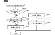
移行したS2103において車両制御ブロック2120は、S2102の干渉予測ブロック110により予測された干渉シーンSiでの干渉予測ペアのうち、ホスト車両2とする少なくとも一方の監視対象車両に対して、干渉リスク制御を与える。そのためにS2103における車両制御ブロック120は、図16に示すように干渉リスク制御ルーチンを実行する。
第二実施形態による干渉リスク制御ルーチンのS2201において車両制御ブロック2120は、干渉予測ペアのうちホスト車両2とする少なくとも一方の監視対象車両に対して、現在の将来パスPfから変更制御可能な緩和パスPrが存在するか否かを、判定する。このとき、干渉予測ペアのうちホスト車両2とする監視対象車両は、例えば緩和パスPrが多い側等の一方であってもよいし、双方であってもよい。
S2201において緩和パスPrが存在する場合には、干渉リスク制御ルーチンがS2202へ移行する。移行したS2202において車両制御ブロック2120は、第一実施形態に準じた緩和パスPrへのパス変更制御を、ホスト車両2とする少なくとも一方の監視対象車両に対しての、通信指令によって与える。S2202の完了により、干渉リスク制御ルーチン及び制御フローの今回実行が終了する。
一方、S2201において緩和パスPrが存在しないことで、S2202によるパス変更制御が禁止される場合には、干渉リスク制御ルーチンがS2203へ移行する。移行したS2203において車両制御ブロック2120は、干渉予測ペアのうちホスト車両2とする少なくとも一方の監視対象車両において、ビーム照射の予定パターンを緩和パターンへ変更するのに必要な最小動作時間Δtが、確保可能か否かを判定する。このとき、干渉予測ペアのうちホスト車両2とする監視対象車両は、例えば最小動作時間Δtが短い側等の一方であってもよいし、双方であってもよい。これらいずれであっても、確保可能か否かの判別は、干渉予測ペアの監視対象車両毎に第一実施形態に準じて実行される。
S2203において最小動作時間Δtが確保可能な場合には、干渉リスク制御ルーチンがS2204へ移行する。移行したS2204において車両制御ブロック2120は、第一実施形態に準じた緩和パターンへのビーム変更制御を、ホスト車両2とする少なくとも一方の監視対象車両に対しての、通信指令によって与える。S2204の完了により、干渉リスク制御ルーチン及び制御フローの今回実行が終了する。
一方、S2203において最小動作時間Δtは確保不可であるために、S2202によるパス変更制御だけでなく、S2204によるビーム変更制御も禁止される場合には、干渉リスク制御ルーチンがS2205へ移行する。移行したS2205において車両制御ブロック2120は、第一実施形態に準じた緩和速度Vrへの速度変更制御を、ホスト車両2とする少なくとも一方の監視対象車両に対しての、通信指令によって与える。このとき、干渉予測ペアのうちホスト車両2とする監視対象車両は、例えば緩和速度Vrへの速度変化量が小さい側又は減速側等の一方であってもよいし、双方であってもよい。S2205の完了により、干渉リスク制御ルーチン及び制御フローの今回実行が終了する。
以上説明したように第二実施形態では、ホスト車両2及びターゲット車両3と通信可能なリモートセンタ2006を構築する制御装置2008が利用されることで、第一実施形態と同様の原理によってセンシング精度を確保することが可能である。
(他の実施形態)
以上、複数の実施形態について説明したが、本開示は、それらの実施形態に限定して解釈されるものではなく、本開示の要旨を逸脱しない範囲内において種々の実施形態及び組み合わせに適用することができる。
以上、複数の実施形態について説明したが、本開示は、それらの実施形態に限定して解釈されるものではなく、本開示の要旨を逸脱しない範囲内において種々の実施形態及び組み合わせに適用することができる。
変形例において制御装置1,2008を構成する専用コンピュータは、デジタル回路及びアナログ回路のうち、少なくとも一方をプロセッサとして有していてもよい。ここでデジタル回路とは、例えばASIC(Application Specific Integrated Circuit)、FPGA(Field Programmable Gate Array)、SOC(System on a Chip)、PGA(Programmable Gate Array)、及びCPLD(Complex Programmable Logic Device)等のうち、少なくとも一種類である。またこうしたデジタル回路は、プログラムを記憶したメモリを、有していてもよい。
変形例において、S204,S2202によるパス変更制御と、S206,S2204によるビーム変更制御と、S207,S2205による速度変更制御とは、S203,S205,S2201,S2203による判定条件の変更により優先順位(実施順)を、第一及び第二実施形態の順とは異ならされていてもよい。ここで特に、パス変更制御及びビーム変更制御の少なくとも一方よりも速度変更制御を優先的に(先に)実行する変形例では、例えば速度変更制御は可能か否か等が、判定条件として採用されるとよい。
変形例において、S204,S2202によるパス変更制御と、S206,S2204によるビーム変更制御と、S207,S2205による速度変更制御とのうち、一種類又は二種類は省かれてもよい。ここまでの説明形態の他、第一及び第二実施形態並びに変化例は、制御装置1,2008のプロセッサ12,2082とメモリ10,2080とを少なくとも一つずつ有した半導体装置(例えば半導体チップ等)として、実施されてもよい。
Claims (11)
- プロセッサ(12,2082)を有し、ホスト車両(2)のビームセンサ(20)においてターゲット車両(3)のビームセンサ(30)に対するビーム干渉を予防するための制御装置(1,2008)であって、
前記プロセッサは、
前記ホスト車両及び前記ターゲット車両のビーム照射に関連する照射関連情報(Ii)を、取得することと、
前記ホスト車両及び前記ターゲット車両間において前記ビーム干渉の発生する干渉シーン(Si)を、前記照射関連情報に基づき予測することと、
予測された前記干渉シーンにおいて前記ビーム干渉のリスクを緩和する干渉リスク制御を、前記ホスト車両に与えることと、を実行するように構成される制御装置。 - 前記干渉リスク制御を与えることは、
将来パス(Pf)を、前記ビーム干渉のリスクを緩和する緩和パス(Pr)へ変更するパス変更制御を、前記ホスト車両に与えることを、含む請求項1に記載の制御装置。 - 前記干渉リスク制御を与えることは、
前記ビーム照射の予定パターンを、前記ビーム干渉を緩和する緩和パターンへ変更するビーム変更制御を、前記ホスト車両に与えることを、含む請求項1又は2に記載の制御装置。 - 前記干渉リスク制御を与えることは、
予測された前記干渉シーンの開始時刻(Ti)から、前記ホスト車両において前記予定パターンの変更に必要な最小動作時間(Δt)以上、遡るように前記ビーム変更制御の開始タイミング(Tc)を設定することを、含む請求項3に記載の制御装置。 - 前記干渉リスク制御を与えることは、
走行速度を、前記ビーム干渉を緩和する緩和速度(Vr)へ変更する速度変更制御を、前記ホスト車両に与えることを、含む請求項1~4のいずれか一項に記載の制御装置。 - 前記干渉リスク制御を与えることは、
前記パス変更制御の禁止される前記干渉シーンにおいて、前記ビーム照射の予定パターンを、前記ビーム干渉を緩和する緩和パターンへ変更するビーム変更制御を、前記ホスト車両に与えることを、含む請求項2に記載の制御装置。 - 前記干渉リスク制御を与えることは、
前記パス変更制御及び前記ビーム変更制御の禁止される前記干渉シーンにおいて、走行速度を、前記ビーム干渉を緩和する緩和速度(Vr)へ変更する速度変更制御を、前記ホスト車両に与えることを、含む請求項6に記載の制御装置。 - 前記ターゲット車両と通信可能な前記ホスト車両に搭載される請求項1~7のいずれか一項に記載の制御装置。
- 前記ホスト車両及び前記ターゲット車両と通信可能なリモートセンタ(2006)を構築する請求項1~7のいずれか一項に記載の制御装置。
- ホスト車両(2)のビームセンサ(20)においてターゲット車両(3)のビームセンサ(30)に対するビーム干渉を予防するために、プロセッサ(12,2082)により実行される制御方法であって、
前記ホスト車両及び前記ターゲット車両のビーム照射に関連する照射関連情報(Ii)を、取得することと、
前記ホスト車両及び前記ターゲット車両の間において前記ビーム干渉の発生する干渉シーン(Si)を、前記照射関連情報に基づき予測することと、
予測された前記干渉シーンにおいて前記ビーム干渉のリスクを緩和する予防する干渉リスク制御を、前記ホスト車両に与えることと、を含む制御方法。 - ホスト車両(2)のビームセンサ(20)においてターゲット車両(3)のビームセンサ(30)に対するビーム干渉を予防するために記憶媒体(10,2080)に記憶され、プロセッサ(12,2082)に実行させる命令を含む制御プログラムであって、
前記命令は、
前記ホスト車両及び前記ターゲット車両のビーム照射に関連する照射関連情報(Ii)を、取得させることと、
前記ホスト車両及び前記ターゲット車両の間において前記ビーム干渉の発生する干渉シーン(Si)を、前記照射関連情報に基づき予測させることと、
予測された前記干渉シーンにおいて前記ビーム干渉のリスクを緩和する干渉リスク制御を、前記ホスト車両に与えさせることと、を含む制御プログラム。
Priority Applications (2)
| Application Number | Priority Date | Filing Date | Title |
|---|---|---|---|
| CN202280042326.3A CN117480402A (zh) | 2021-06-17 | 2022-05-18 | 控制装置、控制方法、控制程序 |
| US18/538,200 US20240123986A1 (en) | 2021-06-17 | 2023-12-13 | Control device, control method, and storage medium |
Applications Claiming Priority (2)
| Application Number | Priority Date | Filing Date | Title |
|---|---|---|---|
| JP2021100905A JP7501457B2 (ja) | 2021-06-17 | 2021-06-17 | 制御装置、制御方法、制御プログラム |
| JP2021-100905 | 2021-06-17 |
Related Child Applications (1)
| Application Number | Title | Priority Date | Filing Date |
|---|---|---|---|
| US18/538,200 Continuation US20240123986A1 (en) | 2021-06-17 | 2023-12-13 | Control device, control method, and storage medium |
Publications (1)
| Publication Number | Publication Date |
|---|---|
| WO2022264740A1 true WO2022264740A1 (ja) | 2022-12-22 |
Family
ID=84526138
Family Applications (1)
| Application Number | Title | Priority Date | Filing Date |
|---|---|---|---|
| PCT/JP2022/020647 WO2022264740A1 (ja) | 2021-06-17 | 2022-05-18 | 制御装置、制御方法、制御プログラム |
Country Status (4)
| Country | Link |
|---|---|
| US (1) | US20240123986A1 (ja) |
| JP (1) | JP7501457B2 (ja) |
| CN (1) | CN117480402A (ja) |
| WO (1) | WO2022264740A1 (ja) |
Cited By (1)
| Publication number | Priority date | Publication date | Assignee | Title |
|---|---|---|---|---|
| WO2024157793A1 (ja) * | 2023-01-27 | 2024-08-02 | ソニーグループ株式会社 | 情報処理方法、情報処理装置、および情報処理システム |
Citations (4)
| Publication number | Priority date | Publication date | Assignee | Title |
|---|---|---|---|---|
| JP2008026095A (ja) * | 2006-07-20 | 2008-02-07 | Fujitsu Ten Ltd | 車載レーダ制御方法及び車載レーダ制御装置 |
| JP2008275400A (ja) * | 2007-04-27 | 2008-11-13 | Fujitsu Ten Ltd | レーダ装置、及び干渉防止方法 |
| US20180128911A1 (en) * | 2016-11-07 | 2018-05-10 | Mando Corporation | Object-sensing system for vehicle and object-sensing method for vehicle |
| US20190056476A1 (en) * | 2017-08-18 | 2019-02-21 | Nxp B.V. | Radar unit, integrated circuit and methods for detecting and mitigating mutual interference |
-
2021
- 2021-06-17 JP JP2021100905A patent/JP7501457B2/ja active Active
-
2022
- 2022-05-18 CN CN202280042326.3A patent/CN117480402A/zh active Pending
- 2022-05-18 WO PCT/JP2022/020647 patent/WO2022264740A1/ja active Application Filing
-
2023
- 2023-12-13 US US18/538,200 patent/US20240123986A1/en active Pending
Patent Citations (4)
| Publication number | Priority date | Publication date | Assignee | Title |
|---|---|---|---|---|
| JP2008026095A (ja) * | 2006-07-20 | 2008-02-07 | Fujitsu Ten Ltd | 車載レーダ制御方法及び車載レーダ制御装置 |
| JP2008275400A (ja) * | 2007-04-27 | 2008-11-13 | Fujitsu Ten Ltd | レーダ装置、及び干渉防止方法 |
| US20180128911A1 (en) * | 2016-11-07 | 2018-05-10 | Mando Corporation | Object-sensing system for vehicle and object-sensing method for vehicle |
| US20190056476A1 (en) * | 2017-08-18 | 2019-02-21 | Nxp B.V. | Radar unit, integrated circuit and methods for detecting and mitigating mutual interference |
Cited By (1)
| Publication number | Priority date | Publication date | Assignee | Title |
|---|---|---|---|---|
| WO2024157793A1 (ja) * | 2023-01-27 | 2024-08-02 | ソニーグループ株式会社 | 情報処理方法、情報処理装置、および情報処理システム |
Also Published As
| Publication number | Publication date |
|---|---|
| CN117480402A (zh) | 2024-01-30 |
| JP7501457B2 (ja) | 2024-06-18 |
| JP2023000213A (ja) | 2023-01-04 |
| US20240123986A1 (en) | 2024-04-18 |
Similar Documents
| Publication | Publication Date | Title |
|---|---|---|
| US11487020B2 (en) | Satellite signal calibration system | |
| CN108136977B (zh) | 自动驾驶系统、自动驾驶控制方法、数据ecu以及自动驾驶ecu | |
| CN111559383B (zh) | 用于基于车辆和边缘传感器数据确定自主车辆(av)动作的方法和系统 | |
| US11495131B2 (en) | Vehicle to vehicle safety messaging congestion control for platooning vehicles | |
| US20210070317A1 (en) | Travel plan generation device, travel plan generation method, and non-transitory tangible computer readable storage medium | |
| US11897505B2 (en) | In-vehicle operation of simulation scenarios during autonomous vehicle runs | |
| CN113692521A (zh) | 信息处理装置、信息处理方法和信息处理程序 | |
| KR20190035115A (ko) | 차량 제어 시스템, 차량 외장형 전자 제어 유닛, 차량 제어 방법 및 애플리케이션 | |
| US20240123986A1 (en) | Control device, control method, and storage medium | |
| US20230182770A1 (en) | Vehicle management device and vehicle management method | |
| JP2022103505A (ja) | 車両制御装置、車両制御方法、およびプログラム | |
| JP2016197279A (ja) | 衝突回避装置及び衝突回避システム | |
| JP6809339B2 (ja) | 自動走行制御装置 | |
| JP7548224B2 (ja) | 情報処理装置、および情報処理方法、並びにプログラム | |
| CN116255973A (zh) | 车辆定位 | |
| US11884296B2 (en) | Allocating processing resources to concurrently-executing neural networks | |
| Huang et al. | Design and implementation of a cooperative collision warning system | |
| JP2022031125A (ja) | 車両管理装置、車両管理方法、車両管理プログラム | |
| US20240240966A1 (en) | Information providing device and information providing method | |
| WO2022244604A1 (ja) | 処理方法、処理システム、処理プログラム | |
| WO2022264962A1 (ja) | 挙動予測システム、挙動予測装置、挙動予測方法、挙動予測プログラム | |
| WO2023286522A1 (ja) | 処理システム、処理装置、処理方法、処理プログラム | |
| US20240010211A1 (en) | Systems and methods for selectively using a vehicle trajectory | |
| US20240200977A1 (en) | Map data generation device, map data generation system, and storage medium | |
| JP2023016628A (ja) | 処理システム、処理装置、処理方法、処理プログラム |
Legal Events
| Date | Code | Title | Description |
|---|---|---|---|
| 121 | Ep: the epo has been informed by wipo that ep was designated in this application |
Ref document number: 22824734 Country of ref document: EP Kind code of ref document: A1 |
|
| WWE | Wipo information: entry into national phase |
Ref document number: 202280042326.3 Country of ref document: CN |
|
| NENP | Non-entry into the national phase |
Ref country code: DE |
|
| 122 | Ep: pct application non-entry in european phase |
Ref document number: 22824734 Country of ref document: EP Kind code of ref document: A1 |