WO2022264721A1 - Duct-type air conditioning ventilation system - Google Patents
Duct-type air conditioning ventilation system Download PDFInfo
- Publication number
- WO2022264721A1 WO2022264721A1 PCT/JP2022/020144 JP2022020144W WO2022264721A1 WO 2022264721 A1 WO2022264721 A1 WO 2022264721A1 JP 2022020144 W JP2022020144 W JP 2022020144W WO 2022264721 A1 WO2022264721 A1 WO 2022264721A1
- Authority
- WO
- WIPO (PCT)
- Prior art keywords
- air
- duct
- unit
- temperature
- conditioning
- Prior art date
Links
- 238000004378 air conditioning Methods 0.000 title claims abstract description 477
- 238000009423 ventilation Methods 0.000 title claims abstract description 99
- 238000001816 cooling Methods 0.000 claims abstract description 55
- 238000010438 heat treatment Methods 0.000 claims abstract description 42
- 238000009413 insulation Methods 0.000 claims abstract description 40
- 230000004087 circulation Effects 0.000 claims abstract description 26
- 238000002156 mixing Methods 0.000 claims abstract description 17
- 230000001143 conditioned effect Effects 0.000 claims description 78
- 238000007664 blowing Methods 0.000 claims description 70
- -1 polypropylene Polymers 0.000 claims description 19
- 238000007791 dehumidification Methods 0.000 claims description 18
- 239000004743 Polypropylene Substances 0.000 claims description 17
- 239000011358 absorbing material Substances 0.000 claims description 16
- 229920001155 polypropylene Polymers 0.000 claims description 16
- 239000000835 fiber Substances 0.000 claims description 13
- 238000011144 upstream manufacturing Methods 0.000 claims description 10
- 229920002799 BoPET Polymers 0.000 claims description 8
- BZHJMEDXRYGGRV-UHFFFAOYSA-N Vinyl chloride Chemical compound ClC=C BZHJMEDXRYGGRV-UHFFFAOYSA-N 0.000 claims description 8
- 229910052782 aluminium Inorganic materials 0.000 claims description 7
- XAGFODPZIPBFFR-UHFFFAOYSA-N aluminium Chemical compound [Al] XAGFODPZIPBFFR-UHFFFAOYSA-N 0.000 claims description 7
- 238000007599 discharging Methods 0.000 claims description 6
- 239000012717 electrostatic precipitator Substances 0.000 claims description 2
- 239000000428 dust Substances 0.000 abstract description 95
- 238000004140 cleaning Methods 0.000 abstract description 34
- 235000019645 odor Nutrition 0.000 abstract description 23
- 238000012423 maintenance Methods 0.000 abstract description 22
- 239000000126 substance Substances 0.000 abstract description 8
- 238000009833 condensation Methods 0.000 description 55
- 230000005494 condensation Effects 0.000 description 55
- 239000004745 nonwoven fabric Substances 0.000 description 19
- 241000894006 Bacteria Species 0.000 description 17
- 230000007423 decrease Effects 0.000 description 17
- 239000003507 refrigerant Substances 0.000 description 17
- 239000011491 glass wool Substances 0.000 description 16
- 239000011810 insulating material Substances 0.000 description 16
- 230000002093 peripheral effect Effects 0.000 description 16
- XLYOFNOQVPJJNP-UHFFFAOYSA-N water Substances O XLYOFNOQVPJJNP-UHFFFAOYSA-N 0.000 description 16
- 239000002245 particle Substances 0.000 description 14
- 238000011045 prefiltration Methods 0.000 description 13
- 239000000463 material Substances 0.000 description 9
- 238000001704 evaporation Methods 0.000 description 8
- 230000008020 evaporation Effects 0.000 description 8
- 230000007774 longterm Effects 0.000 description 6
- 238000000034 method Methods 0.000 description 6
- 229920000728 polyester Polymers 0.000 description 6
- 230000005855 radiation Effects 0.000 description 6
- 239000011347 resin Substances 0.000 description 6
- 229920005989 resin Polymers 0.000 description 6
- 230000003746 surface roughness Effects 0.000 description 5
- 238000005406 washing Methods 0.000 description 5
- 238000010521 absorption reaction Methods 0.000 description 4
- 238000003287 bathing Methods 0.000 description 4
- 238000001514 detection method Methods 0.000 description 4
- 238000010586 diagram Methods 0.000 description 4
- 238000007689 inspection Methods 0.000 description 4
- 230000000737 periodic effect Effects 0.000 description 4
- 230000003068 static effect Effects 0.000 description 4
- 239000003610 charcoal Substances 0.000 description 3
- 238000004891 communication Methods 0.000 description 3
- 238000010411 cooking Methods 0.000 description 3
- 229910052751 metal Inorganic materials 0.000 description 3
- 239000002184 metal Substances 0.000 description 3
- 239000000843 powder Substances 0.000 description 3
- CURLTUGMZLYLDI-UHFFFAOYSA-N Carbon dioxide Chemical compound O=C=O CURLTUGMZLYLDI-UHFFFAOYSA-N 0.000 description 2
- 229920002821 Modacrylic Polymers 0.000 description 2
- CBENFWSGALASAD-UHFFFAOYSA-N Ozone Chemical compound [O-][O+]=O CBENFWSGALASAD-UHFFFAOYSA-N 0.000 description 2
- 239000004698 Polyethylene Substances 0.000 description 2
- 230000009471 action Effects 0.000 description 2
- 239000006227 byproduct Substances 0.000 description 2
- 230000003749 cleanliness Effects 0.000 description 2
- 238000010276 construction Methods 0.000 description 2
- 239000011162 core material Substances 0.000 description 2
- 238000009429 electrical wiring Methods 0.000 description 2
- 239000012774 insulation material Substances 0.000 description 2
- 238000000465 moulding Methods 0.000 description 2
- 229920000573 polyethylene Polymers 0.000 description 2
- 238000003303 reheating Methods 0.000 description 2
- 238000011160 research Methods 0.000 description 2
- 230000004044 response Effects 0.000 description 2
- 238000012546 transfer Methods 0.000 description 2
- 239000012855 volatile organic compound Substances 0.000 description 2
- 239000002023 wood Substances 0.000 description 2
- 241000238876 Acari Species 0.000 description 1
- 241000233866 Fungi Species 0.000 description 1
- 206010020751 Hypersensitivity Diseases 0.000 description 1
- 241000700605 Viruses Species 0.000 description 1
- 238000009825 accumulation Methods 0.000 description 1
- 239000013566 allergen Substances 0.000 description 1
- 230000007815 allergy Effects 0.000 description 1
- 244000052616 bacterial pathogen Species 0.000 description 1
- 238000009395 breeding Methods 0.000 description 1
- 230000001488 breeding effect Effects 0.000 description 1
- 229910052799 carbon Inorganic materials 0.000 description 1
- 229910002092 carbon dioxide Inorganic materials 0.000 description 1
- 239000001569 carbon dioxide Substances 0.000 description 1
- 230000008859 change Effects 0.000 description 1
- 239000011362 coarse particle Substances 0.000 description 1
- 239000011248 coating agent Substances 0.000 description 1
- 238000000576 coating method Methods 0.000 description 1
- 238000011109 contamination Methods 0.000 description 1
- 230000006378 damage Effects 0.000 description 1
- 230000013872 defecation Effects 0.000 description 1
- 230000008021 deposition Effects 0.000 description 1
- 230000006866 deterioration Effects 0.000 description 1
- 230000005611 electricity Effects 0.000 description 1
- 210000003608 fece Anatomy 0.000 description 1
- 239000010419 fine particle Substances 0.000 description 1
- 239000000446 fuel Substances 0.000 description 1
- 230000005484 gravity Effects 0.000 description 1
- 230000036541 health Effects 0.000 description 1
- 230000006872 improvement Effects 0.000 description 1
- 235000015097 nutrients Nutrition 0.000 description 1
- 239000003973 paint Substances 0.000 description 1
- 238000005192 partition Methods 0.000 description 1
- 229920003217 poly(methylsilsesquioxane) Polymers 0.000 description 1
- 229920000139 polyethylene terephthalate Polymers 0.000 description 1
- 239000005020 polyethylene terephthalate Substances 0.000 description 1
- 238000012545 processing Methods 0.000 description 1
- 230000000644 propagated effect Effects 0.000 description 1
- 208000023504 respiratory system disease Diseases 0.000 description 1
- 239000004576 sand Substances 0.000 description 1
- 229920006395 saturated elastomer Polymers 0.000 description 1
- 230000009528 severe injury Effects 0.000 description 1
- 230000008685 targeting Effects 0.000 description 1
- 230000001052 transient effect Effects 0.000 description 1
- 238000009941 weaving Methods 0.000 description 1
- 238000009736 wetting Methods 0.000 description 1
Images


Classifications
-
- F—MECHANICAL ENGINEERING; LIGHTING; HEATING; WEAPONS; BLASTING
- F24—HEATING; RANGES; VENTILATING
- F24F—AIR-CONDITIONING; AIR-HUMIDIFICATION; VENTILATION; USE OF AIR CURRENTS FOR SCREENING
- F24F11/00—Control or safety arrangements
- F24F11/70—Control systems characterised by their outputs; Constructional details thereof
- F24F11/72—Control systems characterised by their outputs; Constructional details thereof for controlling the supply of treated air, e.g. its pressure
- F24F11/74—Control systems characterised by their outputs; Constructional details thereof for controlling the supply of treated air, e.g. its pressure for controlling air flow rate or air velocity
-
- F—MECHANICAL ENGINEERING; LIGHTING; HEATING; WEAPONS; BLASTING
- F24—HEATING; RANGES; VENTILATING
- F24F—AIR-CONDITIONING; AIR-HUMIDIFICATION; VENTILATION; USE OF AIR CURRENTS FOR SCREENING
- F24F3/00—Air-conditioning systems in which conditioned primary air is supplied from one or more central stations to distributing units in the rooms or spaces where it may receive secondary treatment; Apparatus specially designed for such systems
- F24F3/02—Air-conditioning systems in which conditioned primary air is supplied from one or more central stations to distributing units in the rooms or spaces where it may receive secondary treatment; Apparatus specially designed for such systems characterised by the pressure or velocity of the primary air
-
- F—MECHANICAL ENGINEERING; LIGHTING; HEATING; WEAPONS; BLASTING
- F24—HEATING; RANGES; VENTILATING
- F24F—AIR-CONDITIONING; AIR-HUMIDIFICATION; VENTILATION; USE OF AIR CURRENTS FOR SCREENING
- F24F7/00—Ventilation
- F24F7/04—Ventilation with ducting systems, e.g. by double walls; with natural circulation
- F24F7/06—Ventilation with ducting systems, e.g. by double walls; with natural circulation with forced air circulation, e.g. by fan positioning of a ventilator in or against a conduit
- F24F7/10—Ventilation with ducting systems, e.g. by double walls; with natural circulation with forced air circulation, e.g. by fan positioning of a ventilator in or against a conduit with air supply, or exhaust, through perforated wall, floor or ceiling
Definitions
- the present invention relates to a duct-type air-conditioning and ventilation system that air-conditions and ventilates the inside of a building with ducts.
- duct-type air-conditioning and ventilation systems are used relatively often, in which ducts that send air-conditioned and ventilated air from the air conditioner to the rooms and spaces are laid in the building, and air-conditioned and ventilated throughout the building. It is In ducted air conditioning and ventilation systems, ducts are used to blow conditioned or ventilated air into rooms. and dust mite feces, carcasses, VOCs, allergens such as mold, etc.
- the inside of the duct has conditions for the growth of mold, such as "temperature around 5 to 40°C", “adhered moisture due to high humidity of 60% or more”, and “adhered nutrients such as dust and dirt". Due to the temperature difference between the inside and outside of the duct, dust accumulated inside the duct and dew condensation on the non-woven fabric, heat insulating material, etc. of the duct, where mold and mites tend to grow. As the conditioned air passes through the conditioned air, dust, mold, bacteria, and odors get on the conditioned air, and the person who breathes it develops allergies such as respiratory diseases and skin troubles. There is a risk of harming health or being uncomfortable due to odors, etc.
- the duct has poor insulation properties and does not pass through an insulated space, condensation will form on the outer circumference of the duct, wetting the wood, etc. under the duct, causing mold to grow and stains that can be seen from the living space. Otherwise, it will rot and suffer severe damage, and condensation will spread to the electric wire, causing a risk of electric leakage.
- Glass wool which is the insulation material inside the duct, has surface tension and capillary action, and if water enters the gaps between the fibers, even if it is dry, the fibers will stick together, and a large amount of air necessary for the heat insulation function will accumulate. Once condensation occurs inside the duct, it becomes even more likely to condense, reducing the effectiveness of air conditioning and increasing power consumption.
- condensation for example, in cooling operation, cold blown air when the compressor of the air conditioner is running and the thermostat is ON passes through the duct, so the inner peripheral surface of the duct is cooled, for example, to 10 ° C.
- the thermostat is turned off, the compressor stops, and the room air is sucked in, so the blown out air, which contains condensed water condensed on the evaporator and becomes highly humid at the room air temperature, flows through the duct.
- the temperature and humidity of the air are 25° C. and 80% (dew point temperature of 21° C.)
- condensation will form on the inner peripheral surface of the duct.
- the temperature and humidity of that space are close to the outside air temperature in summer.
- a dew point temperature of 18.4°C cold blown air passes through the duct due to cooling operation, and when the duct outer peripheral surface temperature drops below the dew point temperature, dew condensation forms on the duct outer peripheral surface.
- the temperature of the space is close to the outside air temperature, for example, the outside temperature is 0°C and the space temperature is 2°C. Temperature and humidity of 50° C.
- an air-conveying type air conditioning system for each room consists of a ceiling with a chamber structure to which airtightness is added, a plurality of indoor outlets that communicate with the ceiling, and a ceiling outlet that communicates with the ceiling. and a box-shaped main body having an indoor air inlet, a fan provided in the main body so as to suck in from the indoor air inlet and blow out from the ceiling outlet, and cooling heat provided in the ventilation path formed by the fan.
- a heat exchanger for cooling and a heat exchanger for heating are provided, and the airflow surfaces of the heat exchanger for cooling and the heat exchanger for heating are arranged side by side on substantially the same plane so as to divide the airflow path into two, Indoor air is drawn directly into the heating heat exchanger for reheating, and by flowing a small amount of air flow, the latent heat capacity is increased, and dry cold air and cold/hot air with reduced sensible heat capacity are blown out to the ceiling.
- an air conditioning apparatus that can reliably air-condition each room by conveying air into each room without dew condensation even when there are beams or the space above the ceiling is narrow (see, for example, Patent Document 1).
- a temperature adjustment unit for adjusting the temperature of the air that is sent to the room through the air supply duct;
- a humidity detection unit that measures the humidity of the air and a signal for turning off the temperature adjustment unit is detected, if the humidity measured by the humidity detection unit is greater than a predetermined value, the temperature adjustment unit is turned on. If the humidity measured by the humidity detection unit is lower than the predetermined value, the temperature adjustment unit is turned off, so that the inside of the air supply duct during heating operation in winter
- Patent Document 2 A device capable of suppressing the occurrence of dew condensation on the surface is known (see, for example, Patent Document 2).
- an air intake chamber having an air intake opening to the outside space of the living room to be air-conditioned, and a room having a heat exchanger for cooling or heating the air sucked in through the air intake chamber.
- an air duct for conveying the air cooled or heated by the indoor unit to the outlet of the living room, arranged downstream of the heat exchanger, and cooled by the heat exchanger during cooling
- a reheating coil for heating dehumidified air, whereby the duct member of the blower duct is not coated with thermal insulation or is coated with thin thermal insulation (see, for example, US Pat.
- a paint film containing charcoal powder is formed on the inner surface of the duct, and the duct connects the air intake and air outlet with the air blower. It is known that a house ventilation system is constructed to suppress the generation of mold and bad odors in ducts due to charcoal powder, and to provide a comfortable living environment by removing odors contained in the air. (See Patent Document 4, for example).
- JP-A-11-237079 Japanese Patent No. 6712763 Japanese Utility Model Laid-Open No. 7-18129 JP-A-2001-248886
- the duct type air conditioning and ventilation system of the present invention provides air outlets in rooms and heat insulating spaces in a highly airtight and highly insulated building, and air-conditions the air conditioning units provided in the building and the air outlets.
- the space is connected by a duct, the air-conditioning duct is passed through the heat-insulated space, the air-conditioning unit produces purified air-conditioning air, the purified air-conditioning air flows from the air-conditioning unit to the air outlet, and the air outlet is provided.
- a ducted air-conditioning and ventilation system having an air passage returning from the room and the adiabatic space to the air-conditioning unit as a circulation passage, wherein the air-conditioning unit includes an air intake section, An air conditioning unit, a mixing unit, and a plurality of air blowing units are provided, and a filter unit A, a filter unit B, and a filter unit C are provided in the suction unit, the air conditioning unit, and the plurality of air blowing units, respectively.
- the air sucked from the suction section is cleaned by the filter section A, part of the air sucked from the suction section is conditioned and cleaned by the air conditioning section and the filter section B, and then removed from the air conditioning section.
- the blown air and the remaining part of the air sucked from the suction part are mixed by the plurality of blowing parts in the mixing part upstream of the filter part C, and the air conditioning duct is mixed.
- Air-conditioning air having a temperature within 5K during cooling and within 10K during heating is produced with respect to the temperature of the surrounding air, and the plurality of air blowing units and the filter unit C further clean the conditioned air, and the air outlet.
- An outdoor air introduction passage for introducing outdoor air is provided in the room, an introduction fan and a filter are provided in the outdoor air introduction passage, the outdoor air to be introduced is cleaned, and the room or the air outlet is provided without the circulation passage or the air outlet.
- An indoor air discharge path is provided for discharging the air in the building from at least one of the adiabatic spaces without an outlet to the outside, and an exhaust fan is provided in the indoor air discharge path so that part of the air in the circulation path is provided.
- the temperature of the air around the air-conditioning duct produced by the air-conditioning unit is within 5K during cooling and within 10K during heating. Blowing air from the air outlet of the heat insulating space to air-condition the rooms in the highly airtight and highly heat insulating building and the heat insulating space above and below, so the inside of the building, including the heat insulating space with a large air conditioning load such as solar radiation load, is comfortable and uniform temperature and humidity. easy to become.
- the air conditioning unit that produces conditioned air is provided with a filter section to purify the air in the building, an introduction fan and filter are provided in the outdoor air introduction path to purify the outdoor air to be introduced, and no outlet is provided.
- a healthy and comfortable space can be achieved without odors.
- a duct type air-conditioning and ventilation system can be obtained that does not require maintenance such as replacement or cleaning of ducts even when used for a long period of time, and can always provide healthy and comfortable air-conditioning and ventilation in the building.
- the highly airtight and highly insulated building has a roof insulation specification and a basic insulation specification, the insulation space is an attic space and an underfloor space, and the total air volume of the plurality of air blowing units is greater than the air volume of the air conditioning unit. In many cases, the air volume of the air blower is not zero.
- a highly airtight and highly insulated building is made into roof insulation specifications and basic insulation specifications, the attic space at the top of the building, which is easily affected by solar radiation and outside temperature, is made a heat insulation space, and the ground temperature at the bottom of the building is reduced.
- the underfloor space which is affected and tends to become highly humid, is treated as an insulated space, each of which is air-conditioned.
- a part of the air sucked from the suction part is not sucked into the air conditioning part, but joins and mixes with the air blown from the air conditioning part in the mixing part, and the air volume of the air conditioning part, the set temperature, the air volume of the blowing part, etc.
- By adjusting the temperature of the air around the air conditioning duct it is possible to stably create a large amount of conditioned air within 5K during cooling and within 10K during heating with energy saving. Therefore, a duct-type air-conditioning and ventilation system is obtained in which dew condensation is unlikely to occur in the air-conditioning duct.
- the filter section provided in the intake section of the air conditioning unit cleans all the air sucked into the air conditioning unit and flows into the air conditioning duct.
- the part Since the part is located in the suction part, it is possible to obtain a duct type air conditioning ventilation system that is easy to maintain such as cleaning. Furthermore, the air volume of the air blower is much larger than the air volume of the air conditioning unit, and the temperature of the room and space is within 5K during cooling and within 10K during heating. It can be produced stably, and the temperature of the room and space does not fluctuate significantly, such as overshooting, and it is stable for a long time. In the air conditioning unit, the thermo ON state continues for a long time with a small temperature difference, and the compressor continues to operate at a low frequency.
- the moisture in the intake air condenses on the evaporator, the amount of dehumidification removed increases due to long-term operation, the absolute humidity of the blown air continues for a long time, and the absolute humidity of the conditioned air also decreases.
- the relative humidity in the air-conditioning duct, the room, and the space through which the air-conditioned air flows is also reduced.
- the air volume of the air blowing unit whose running cost per unit air volume is significantly lower than the air volume of the air conditioning unit whose running cost per unit air volume is high is increased. It is energy saving because it is a system that creates air conditioning ducts and passes air conditioning ducts.
- the air conditioning unit has a reheat dehumidification function.
- one heat exchanger functions as an evaporator through which low-temperature, low-pressure refrigerant flows
- the other heat exchanger functions as a reheater, through which medium-temperature and medium-pressure refrigerant flows.
- the air is blown out with a low absolute humidity, and the reheat dehumidification thermostat is turned ON for a long time, and the compressor continues to operate.
- the so-called evaporation temperature falls below the dew point temperature of the intake air, causing the moisture in the intake air to condense on the evaporator.
- a type air conditioning ventilation system is obtained.
- another means is to provide an air purifier of HEPA filter type or electrostatic precipitator type in the circulation path or the air conditioning unit.
- a HEPA filter type or electric dust collection type air purifier is installed in the circulation path or the air conditioning unit to remove mold spore level particles contained in the conditioned air, so mold grows more in the air conditioning duct through which the conditioned air passes.
- Another means is to have at least one of a polypropylene film, a soft vinyl chloride film, and a PET film on the surface inside the air-conditioning duct through which the air-conditioning air flows.
- a polypropylene film, a soft vinyl chloride film, and a PET film on the surface inside the air-conditioning duct through which the air-conditioning air flows.
- another means has a temperature sensor for detecting the temperature of the room or the heat insulating space, a temperature setting section for setting the temperature, a temperature sensor for detecting the temperature of the mixing section, and two It has a control unit for controlling the air conditioning unit and the blower unit based on the detected value of the temperature sensor and the set temperature of the temperature setting unit.
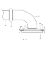
- another means is to replaceably provide a heat insulating duct having an aluminum fiber sound absorbing material between the air conditioning duct and the air outlet on the surface inside the duct through which the air conditioning air flows.
- a sound-absorbing and heat-insulating duct with aluminum fiber sound-absorbing material with high sound absorption and weather resistance is installed on the surface of the inside of the duct where air-conditioned air flows, and can be replaced from the mounting hole between the air outlet and the air-conditioning duct. Therefore, it is possible to reduce noise from air outlets in rooms such as bedrooms where quietness is required, and dust adheres to the surface of the sound absorbing material, so compared to sound absorbing materials such as glass wool, mold is less likely to occur.
- the inside of a highly airtight and highly insulated building is air-conditioned so that the temperature and humidity are uniform, fresh and clean outdoor air is introduced, dirty indoor air containing moisture is exhausted, and the air in the building is cleaned.
- a duct type air-conditioning and ventilation system that does not require maintenance such as replacement or cleaning of air-conditioning ducts even if used for a long period of time, and that can always air-condition and ventilate a building in a healthy and comfortable manner.
- a duct-type air-conditioning and ventilation system that can set the temperature of a room or space according to the user's preference and automatically adjust to the set temperature while preventing dew condensation inside and outside the air-conditioning duct.
- the sound-absorbing and heat-insulating duct reduces noise from the air-conditioning outlet while preventing the growth of mold. In the unlikely event that the duct needs to be replaced, it can be replaced from the outlet's mounting hole.
- a configuration diagram of a duct type air conditioning and ventilation system according to Embodiment 1 of the present invention Longitudinal cross-sectional view of the air conditioning unit of the same system Longitudinal cross-sectional view of the air conditioning unit of the system Cross-sectional view of air conditioning ducts, etc. of the same system
- Control block diagram of the same system Construction drawing of a sound absorbing and heat insulating duct of the same system according to Embodiment 2 of the present invention Cross-sectional view of the sound-absorbing and heat-insulating duct of the same system
- FIG. 1 is a configuration diagram of a duct-type air-conditioning and ventilation system 1 according to Embodiment 1 of the present invention.
- a duct-type air-conditioning and ventilation system 1 is installed in a building 2 which is a highly airtight and highly insulated house.
- the room refers to a living room
- the space refers to a non-living room. It refers to a room
- a non-residential room refers to a non-residential room.
- the building 2 has an outer skin covered with a heat insulating material (not shown) and an airtight sheet (not shown) without gaps, the roof 3 has a roof heat insulating specification, the foundation 4 has a basic heat insulating specification, and the windows have triple glass resin sashes.
- a heat insulating sash 5 such as a door is a heat insulating door (not shown), and the entire room and space in the building 2 including the attic space (heat insulating space) 6 and the underfloor space (heat insulating space) 7 are heat insulating spaces.
- Heat insulation methods can be broadly divided into external heat insulation and internal heat insulation, and each method can be adopted according to its merits/disadvantages.
- the object is building 2.
- the continuity of the airtight layer is maintained by attaching airtight tape etc. to the joints of the airtight sheet, and building 2 clears at least the C value of 1.0. do.
- an air-conditioning unit 10 with high airtightness and heat insulation which is covered with a wall and a heat insulating material and airtightly treated, is provided on a landing 12 of stairs in an entrance hall 11.
- the air-conditioning unit 10 is also provided with a closed door (not shown) that allows entry and exit from the staircase landing 12 by opening and closing for maintenance, and that is highly airtight when closed.
- the air-conditioning unit 10 is provided on the landing 12 of the stairs, but it is also installed in non-residential rooms such as the attic space 6, the underfloor space 7, under the stairs (not shown), and the machine room (not shown). , may be provided.
- An air conditioning unit 10 that generates conditioned air includes a plurality of blowers 13 and an air conditioning unit 16 that is connected to an air conditioning outdoor unit 14 installed outdoors through refrigerant pipes and electrical wiring 15 .
- the air conditioning unit 16 has a heat exchanger (not shown) and an air blower (not shown), and the air blowing unit 13 has a fan (not shown) and a motor (not shown).
- Air outlets 22, 23, and 24 are attached to the floors or ceilings of room A20 and room B21 in building 2 and entrance hall 11, respectively, and air outlets 25 and 26 are provided in attic space 6 and underfloor space 7, respectively. is provided, and the air outlet is an air supply grill that blows out conditioned air, and the wind direction can be changed.
- air outlets are provided in room A20 and room B21 as living rooms, but may be provided in LDK, bedroom, children's room, work room, washroom, toilet, bathroom, kitchen, etc.
- the outlets are provided in the entrance hall 11, the attic space 6, and the underfloor space 7, but the outlets may be provided in the stair landing 12, under the stairs, the machine room, the corridor, the storeroom, the closet, the shoe cupboard, etc. .
- a plurality of blower sections 13 and outlets 22, 23, 24, 25, and 26 are connected one-to-one to one by air-conditioning ducts 30, 31, 32, 33, and 34, respectively. Although not shown in FIG. 1 for simplification, there are other rooms and spaces with air outlets. Ventilate.
- the air-conditioning ducts 30, 31, 32, 33, and 34 are flexible ducts with an inner diameter of 150 mm with high heat insulation and moisture resistance.
- the inside of the vertical shaft 35 which is a heat-insulating space that extends vertically through the building 2 is passed through the rear side of the air conditioning unit 10 .
- the vertical shaft 35 is far from the outer skin of the building 2 and is surrounded by rooms and spaces, so it is not affected by outdoor air and solar radiation, and the temperature tends to be the same as that of the rooms and spaces. .
- the air conditioning ducts 30, 32, 34 are lowered downward, and the other ends of the air conditioning ducts are connected to the outlets 22, 24, 26 through the underfloor space 7, which is the heat insulating space at the bottom of the building 2.
- the ducts 31 and 33 are raised upward and connect the other side of the air conditioning ducts to the outlets 23 and 25 through the attic space 6 which is the heat insulating space at the top of the building 2 .
- the wind speed inside the duct should be 5 to 7 m/s or less, and depending on the PQ (static pressure - air volume) characteristics of the blower and ventilation fan, there is a margin in the air volume and static pressure at the point of use.
- the wind speed is about 4.7 m / s and 5 to 7 m / s or less. becomes. If the inner diameter is not 100 mm or more, equipment such as a brush for cleaning the inside cannot be inserted, making maintenance difficult.
- the inner diameter is set to 150 mm by increasing the inner diameter as long as the duct space permits so as to reduce the As a result, the air-conditioning air generated in the air-conditioning unit 10 passes through the air-conditioning ducts 30, 31, 32, 33, and 34 that are all passed through the heat-insulating space by the air blower 13, and flows through the outlets 22, 23, and 24. , 25 and 26 to room A20, room B21, entrance hall 11, attic space 6, and underfloor space 7, air-conditioning air ducts (thick arrows) are formed.
- the air-conditioning duct is connected to the air outlet through the vertical shaft 35, the underfloor space 7, and the attic space 6, but it is a heat insulating space far from the outer skin of the building 2, and is surrounded by rooms and spaces. If it is enclosed, it may be, for example, an inter-floor space (not shown), a room or a part of the space surrounded by wood (not shown).
- Exhaust ports 40 and 41 such as undercuts of the doors (not shown) of room A20 and room B21 are opened between the entrance hall 11 and the entrance hall 11 .
- exhaust ports 42, 43 such as exhaust louvers are provided between the attic space 6, the underfloor space 7 and the entrance hall 11, exhaust ports 42, 43 such as exhaust louvers are provided.
- a return air port 44 (intake part) such as a suction grille is provided at the top of a sealed door (not shown) on the landing 12 side of the stairs of the air conditioning unit 10, and all the air sucked into the air conditioning unit 10 is It is sucked from the return air port 44 (suction portion).
- the air in the room A20, the room B21, the attic space 6, and the underfloor space 7 passes through the air outlets 40, 41, 42, and 43, enters the entrance hall 11, and exits the air conditioning unit 10 through the return air outlet 44.
- a return airway (thin arrow) is formed.
- a circulation path (not shown) is formed by connecting the air conditioning blower path and the return air path.
- the attic space 6 is provided with a heat exchange air unit 50 that collects all the heat of the indoor air to the outdoor air when the outdoor air is introduced into the room and the indoor air is discharged to the outside, and the entire building 2 is ventilated.
- the heat exchange air unit 50 has a 24-hour ventilation air volume of 125 m 3 /h, a strong notch ventilation air volume of 250 m 3 /h, and a total heat exchange rate of about 70%.
- the ceiling of the toilet 51 in the building 2 is provided with a ventilation outlet 52 such as an exhaust louver for exhausting the air in the toilet 51, and is connected to the heat exchange air unit 50 by an exhaust duct A53.
- An outdoor exhaust hood A54 is provided in a through-hole in the outer wall of the building 2, and is connected to the heat exchange air unit 50 by an exhaust duct B55.
- the heat exchange air unit 50 includes an introduction fan (not shown) for introducing outdoor air, an exhaust fan (not shown) for discharging indoor air, a motor (not shown), and a motor (not shown) for recovering all the heat of the indoor air to the outdoor air. and a pre-filter 64 for the element, which is arranged on the indoor air inlet side of the heat exchange element 63 to prevent dust and the like of the indoor air from adhering to the element.
- the element pre-filter 64 is a polyester or modacrylic non-woven fabric having a thickness of 10 mm to 20 mm, is used at a standard wind speed of 2.5 m/s, has an efficiency (weight method) of 75%, and can be recycled by washing.
- maintenance such as cleaning of the heat exchange element 63 and element pre-filter 64 can be performed periodically by providing a maintenance space around the heat exchange air unit 50 or by providing an inspection opening in the lower ceiling. easily possible.
- the indoor air passes through the ventilation exhaust port 52 through the exhaust duct A53, the heat exchange air unit 50 recovers all the heat, the exhaust duct B55, and the outdoor exhaust hood A54 exhausts to the outside.
- the indoor air exhaust path is formed between the ventilation exhaust port 52 and the outdoor exhaust hood A54, and is formed by the exhaust duct A53, the heat exchange air unit 50, and the exhaust duct B55.
- the element pre-filter 64 of the heat exchange unit 50 is provided in the indoor air discharge path, other filters may be provided in addition to the element pre-filter 64 or together with the element pre-filter 64 .
- the exhaust fan of the heat exchange unit 50 is provided in the indoor air discharge path, an exhaust fan other than the exhaust fan or together with the exhaust fan may be provided.
- An outdoor air supply hood 56 is provided in a through hole in the outer wall of the building 2 and connected to the heat exchange air unit 50 by an air supply duct A57. In the middle of the air supply duct A57, in the attic space 6, a filter box 59 having an outside air cleaning filter 58 for cleaning the outdoor air to be introduced is provided, and an inspection opening is provided in the lower ceiling to facilitate maintenance such as cleaning the filter.
- the outside air cleaning filter 58 is a fine particle filter made of polyethylene terephthalate, polypropylene or PP resin and having a thickness of 35 mm. It is designed to be exchanged once every two years due to the collection efficiency.
- a ventilation air supply port 60 for blowing outdoor air into the building 2 is provided, and is connected to the heat exchange air unit 50 with an air supply duct B61. ing.
- the outdoor air is introduced from the outdoor air supply hood 56, passes through the air supply duct A57, is cleaned by the filter box 59, recovers all the heat in the heat exchange air unit 50, and passes through the air supply duct B61. , is introduced into the room from the ventilation air supply port 60.
- the outdoor air introduction path is formed between the outdoor air supply hood 56 and the ventilation air supply port 60, and is formed by the air supply duct A57, the filter box 59, the heat exchange air unit 50, and the air supply duct B61.
- the outside air cleaning filter 58 of the filter box 59 is provided in the outdoor air introduction path, but other filters besides the outside air cleaning filter 58 or together with the outside air cleaning filter 58 may be provided.
- the introduction fan of the heat exchange unit 50 is provided in the outdoor air introduction path, an introduction fan other than the introduction fan or together with the introduction fan may be provided.
- the exhaust duct A53 is an exhaust duct provided in the attic space 6 between the ventilation exhaust port 52 and the heat exchange unit 50, there is little possibility of condensation in the duct, and dust and moisture accumulate inside the duct and absorb water.
- This is a non-insulated duct with an inner diameter of 150 mm, which is composed only of a polypropylene duct without a heat insulating material or non-woven fabric inside the duct so as to prevent the heat from leaking.
- the exhaust duct B55 and the air supply duct A57 are provided in the attic space 6 between the outdoor exhaust hood A54 or the outdoor air supply hood 56 and the heat exchange air unit 50, and are in contact with the outdoor air.
- the specifications are the same as those of air conditioning ducts, which are flexible and have high durability and moisture resistance. Since the air supply duct B61 is provided in the attic space 6 between the ventilation air supply port 60 and the heat exchange air unit 50, it has an inner diameter of 150 mm, high heat insulation, moisture resistance, and flexibility. It has the same specifications as the duct. Since the heat exchange air unit 50, the exhaust duct B55, and the air supply duct A57 are in contact with the outdoor air, there is a possibility that condensation and dust may enter from the outside, so that periodic cleaning and replacement are possible. , it is necessary to set up an inspection door nearby.
- the toilet 51 is not provided with an outlet for blowing conditioned air, but is provided with a louver 65 through which air flows in and out between the toilet 51 and the entrance hall 11 .
- the heat exchange air unit 50 By the operation of the heat exchange air unit 50, fresh outdoor air cleaned by the outside air cleaning filter 58 provided in the outdoor air introduction path is introduced by the introduction fan of the heat exchange air unit 50, and the so-called dirty air of the toilet 51 and the like is introduced.
- Air polluted with moisture in the zone and part of the air that has conditioned the room and the heat-insulated space pass through the indoor air discharge path from the ventilation exhaust port 52, and are discharged by the heat exchange air unit 50 by the exhaust fan of the heat exchange air unit 50. After the total heat is exchanged with the outdoor air by the heat exchange element 63, it is discharged to the outside. It is possible to reduce dust, moisture, mold spores, etc. in the building while ventilating the building 2 while saving energy by discharging it to the outside and exchanging heat.
- the toilet 51 is provided with the ventilation outlet 52. However, it can be used in rooms other than the toilet, such as washrooms, bathrooms, kitchens, etc., where odors, moisture, harmful substances, etc.
- a so-called dirty zone which is a space
- the ventilation exhaust port 52 may be provided in a room or space downstream of the circulation path (return air path) such as the entrance hall 11 or the air conditioning unit 10. In that case, part of the indoor air in the room or space is The dust and moisture generated in the room or space are discharged to the outside of the room together with the dust and moisture generated in the normal life.
- a port 52 must be provided, or a separate ventilation fan, which will be described later, must be provided.
- a ceiling-embedded ventilation fan 67 with a strong notch air volume of 80 m 3 /h is provided to exhaust the air in the bathroom 66, and the exhaust duct C68 penetrates the outer wall of the building 2. It is connected to an outdoor exhaust hood C69 provided in the hole.
- the exhaust duct C68 is provided in the heat insulating space between the outdoor exhaust hood C69 and the ceiling-embedded ventilation fan 67, and since it is a duct in contact with the outdoor air, it has an inner diameter of 100 mm, high heat insulation, moisture resistance, and flexibility. It has the same specifications as the air conditioning duct.
- the bathroom 66 is not provided with an outlet for blowing conditioned air, but is provided with a louver 70 through which the air flows in and out between the bathroom 66 and the entrance hall 11. A part of the air that has conditioned the room and the heat-insulating space that has returned to 11 flows from the garage 70 into the bathroom 66, and when stable, the air quality (temperature, humidity, cleanliness, etc.) in the bathroom 66 is close to that of the conditioned air. becomes.
- the ceiling-mounted ventilation fan 67 is provided in the bathroom 66.
- Ventilation fans may be provided in rooms and spaces where odors, large amounts of moisture, harmful substances, etc. are likely to be temporarily generated and accumulated, and these can be quickly exhausted directly to the outside.
- the ceiling-mounted ventilation fan 67 is provided, but a ventilation fan that can quickly exhaust air directly to the outside may be used, for example, a wall-mounted type or an intermediate duct type. , a heat exchange air unit that is resistant to deterioration due to moisture in bathrooms, oil in kitchens, etc. may be used.
- the air conditioning unit 10 is provided with a plurality of filters (filter sections) for cleaning the air inside the building 2 .
- filters filters
- a return air port filter 75 filter department
- the air conditioning unit 16 is provided with an air conditioning unit filter 76 (filter unit) upstream of the heat exchanger (not shown) for cleaning the intake air and preventing dust from adhering to the heat exchanger.
- the air blowing section 13 on the upstream side of the fan (not shown), the sucked air is cleaned, and in the air conditioning ducts 30, 31, 32, 33, 34, the room A20, the room B21, the entrance hall 11, the attic space 6
- a blower filter 77 (filter section) is provided so as not to blow dust or the like into the underfloor space 7 . Both the air conditioning unit filter 76 and the blower unit filter 77 can be removed from the main body for maintenance such as periodic cleaning.
- the return air port filter 75 is a polyester or modacrylic non-woven fabric with a thickness of 15 mm to 30 mm, is used at a standard wind speed of 1 m/s, has an efficiency (weight method) of 80% or more, and can be recycled by washing.
- the air-conditioning unit filter 76 is a filter made by weaving polypropylene fibers in a honeycomb shape (honeycomb shape) and molded in a resin frame. is easy.
- the blower filter 77 is a non-woven fabric made of polyester or the like and having a thickness of 2 mm. It is used at a standard wind speed of 2 m/s, has an efficiency (weight method) of 30%, has a low pressure loss, and can be regenerated by washing. If it is desired to reduce the frequency of maintenance such as cleaning, a filter made of polypropylene fibers woven in a honeycomb shape may be formed in a resin frame, as in the case of the air conditioning unit filter 76, although the efficiency is slightly reduced.
- the air cleaner 80 Downstream of the return air port 44 in the air conditioning unit 10 and between the air conditioning section 16 and the air blowing section 13, an electric dust collecting type air cleaner 80 is provided.
- the air cleaner 80 has a prefilter and an electric dust collector.
- the pre-filter is a 20 to 50-mesh SUS coarse-mesh filter located upstream of the electric dust collector. Coarse particles with a particle size of 10 to 20 ⁇ m or more are removed and passed through an electric dust collector.
- the pre-filter may be made of resin such as polypropylene depending on the application.
- An electric dust collector downstream of the pre-filter removes even finer particles with a particle size of 0.3 ⁇ m or more, such as airborne mold spores, dust, pollen, yellow sand, PM2.5, and other airborne particles.
- an electric dust collector type air purifier 80 is provided. It may be selected according to the type and degree of dust, bacteria, harmful substances, etc. to be removed, the shape of the machine, the shape of the air conditioning unit 10, the air velocity in the air conditioning unit 10, the frequency of maintenance such as cleaning, and the like. For example, when targeting viruses with a particle diameter of 0.1 ⁇ m or more that can be captured by a HEPA filter, the HEPA filter type is used. The pre-filter and the electric dust collector can be easily cleaned and replaced by opening the sealed door of the air conditioning unit 10 .
- the air cleaner 80 is provided in the air conditioning unit 10 in this embodiment, it may be provided in the middle of the return air path returning to the air conditioning unit 10 from the room 20 or the like.
- the blower section 13 in the air conditioning unit 10 is separated from the blower (not shown) of the air conditioning section 16, but the air conditioning blower function for exchanging heat with a heat exchanger (not shown) Any configuration of the blower unit 13 and the blower may be used as long as the conveying function of blowing air to the room or each space works effectively.
- the air-conditioning unit 10 is a closed air-conditioning room covered with walls and heat insulating material, but it may be a compact housing covered with sheet metal or heat insulating material.
- part of the space such as the landing 12 of the stairs, the bottom of the stairs, the corridor, etc. may be surrounded by a wall or the like, provided with the air conditioning unit 16, the air blowing unit 13, and the like, and may be a partially open space.
- the size of the air conditioning unit 16 and the air blowing unit 13 be such that maintenance can be easily performed.
- an air conditioning unit controller 110 having a sensor and a control unit for detecting the temperature, humidity, and dust concentration of the air after passing through the air purifier 80 is provided below the air purifier 80 in the air conditioning unit 10.
- the temperature of the entrance hall 11 and the temperature of the entrance hall 11 are set with a sensor for detecting the temperature, humidity, and dust concentration of the air in the entrance hall 11 that is mixed and homogenized.
- a room temperature controller 120 having a temperature setting unit and a control unit for controlling the temperature is provided.
- the air conditioning unit controller 110 and the room temperature controller 120 are connected by signal lines for exchanging signals with the control section of the air conditioning section 16 and the control section of the air blowing section 13 .
- FIG. 2 is a longitudinal sectional view of the air conditioning unit 10.
- the air-conditioning unit 10 which is covered and sealed with walls (including a closed door) and heat insulating material, is provided on the stair landing 12 of the entrance hall 11, and a closed door (not shown) that contacts the stair landing 12 of the entrance hall 11. is provided with a return air port 44 (suction portion) through which air from the room A20 or the like returns to the air conditioning unit 10, and includes a return air port filter 75 (filter portion).
- the air conditioning unit 16 is provided in front of the return air port 44 and away from the back, and the plurality of air blowing units 13 are embedded in the vertical shaft 35 on the back side of the air conditioning unit 10 below the air conditioning unit 10. ing.
- the air conditioning unit 16 blows part of the air sucked in from the return air port 44 by the blower unit 13 (air mixed with the outdoor air introduced from the rooms and spaces in the entrance hall 11) using a blower (not shown). ), the air is sucked from the suction port 86 on the upper surface and the front surface, cleaned by the air conditioning unit filter 76 (filter unit), and heat-exchanged with the refrigerant by the heat exchanger (not shown). blow downwards.
- An air purifier 80 is provided between the air conditioning unit 16 , the return air port 44 and the air blowing unit 13 so as to partition the upper and lower parts of the air conditioning unit 10 .
- a mixing unit 85 in which the air sucked from the return air port 44 (at the entrance hall 11, the return air from the room or space and the outdoor air introduced are mixed. This is a space where part of the air blown out from the air conditioning unit 16 and the air blown out from the air conditioning unit 16 are mixed.
- the air blower 13 uses a fan (not shown) to blow the air blown out from the air conditioner 16 and a part of the air that bypasses the air conditioner 16 without being sucked into the air conditioner 16 from the return air port 44 and transfers it to the air purifier 80.
- the conditioned air mixed in the mixing unit 85 is sucked from the suction port 88, further cleaned by the blower unit filter (filter unit) 77, and flows into the air conditioning ducts 30, 31, 32, 33, and 34.
- FIG. 3 is a longitudinal sectional view of the air conditioning unit 16.
- the air sucked in from the upper and front suction ports 86 of the housing of the air conditioning unit 16 is cleaned by the air conditioning unit filter 76, heat-exchanged with the refrigerant by the heat exchangers 91 and 92, and blown by the blower 90.
- the air is blown out from the outlet 87 in the direction in which the louver 94 faces.
- the air conditioning unit 16 has three operation modes of cooling/heating/reheat dehumidification, and the heat exchangers 91 and 92 have a structure in which the characteristics of the flowing refrigerant change depending on each operation mode, and the roles are switched.
- both the heat exchangers 91 and 92 function as evaporators through which low-temperature, low-pressure refrigerant flows
- both the heat exchangers 91 and 92 function as condensers through which high-temperature, high-pressure refrigerant flows. do.
- the heat exchanger 91 functions as an evaporator through which a low-temperature, low-pressure refrigerant flows
- the heat exchanger 92 functions as a reheater through which a medium-temperature, medium-pressure refrigerant flows.
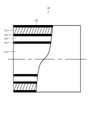
- FIG. 4 is a sectional view of the air conditioning ducts 30, 31, 32, 33, 34, air supply duct B61, exhaust duct B55 and air supply duct A57.
- the air conditioning ducts 30, 31, 32, 33, 34, the air supply duct B61, the exhaust duct B55, and the air supply duct A57 are flexible ducts with an inner diameter of 150 mm with high heat insulation and moisture resistance.
- the structure of the duct consists of, from the outside, an outer covering material 100 such as a flexible polyethylene sheet having a thickness of about 0.08 mm, a heat insulating material 101 such as glass wool having a thickness of about 25 mm and a density of about 24 kg/m 3 , and polyester non-woven fabric.
- the internal covering material 102 such as a polypropylene film, a soft vinyl chloride film, a PET film, etc. with a thickness of about 0.1 mm, which is non-breathable, non-moisture permeable, and has a small surface roughness (surface unevenness), air conditioning air
- a core material (not shown) for molding such as polypropylene resin is provided between the inside of the heat insulating material 101 and the inner covering material 102, and the air conditioning ducts 30 to 34 etc. are provided. Even if it is bent, it does not buckle, and the cross-sectional area of the internal air passage 103 can be secured.
- glass wool having a thickness of 25 mm and a density of about 24 kg/m 3 is used as the heat insulating material 101 .
- the duct space may be secured by using glass wool or the like having a density of 100 kg/m 3 or more and a thickness of 10 mm or less. In that case, since the insulation performance of the duct is slightly reduced, it is necessary to strengthen the insulation of the insulation space through which the duct passes, or to pass the duct through the insulation space away from the outer skin of the building 2. It is desirable to take measures such as increasing the air conditioning capacity by increasing the number of
- FIG. 5 is a control block diagram of the same system.
- the air conditioning unit controller 110 detects the temperature of the conditioned air in the mixing section 85 after passing through the air purifier 80 and before being sucked into the blowing section 13, and the humidity of the same air. and a dust sensor 113 for detecting the mass concentration of dust in the air.
- the room temperature controller 120 detects the temperature of the air sucked into the return air port 44 (air mixed with the outdoor air introduced from the rooms and spaces in the entrance hall 11) and the humidity of the same air. It has a humidity sensor 122 for detection, a dust sensor 123 for detecting the mass concentration of dust in the air, and a temperature setting section 125 for setting the temperature of the air, and transmits data to the control section 124 .
- the air conditioning unit 16 has an intake temperature sensor 133 that detects the temperature of the intake air heat-exchanged by the heat exchangers 91 and 92, transmits data to the control unit 130, and controls the air blower 90 according to instructions from the control unit 130. It has a blower controller 131 that controls the number of revolutions and a louver controller 132 that controls the angle of the louver 94 .
- the air conditioner outdoor unit 14 includes a compressor control unit 136 that controls the rotation speed of the compressor (not shown) and an outdoor fan control unit 137 that controls the rotation speed of the outdoor fan (not shown) according to instructions from the control unit 135.
- the blower unit 13 has a motor control unit 141 that controls the rotation speed of a motor (not shown) according to instructions from the control unit 140 .
- the controller 114 of the air conditioning unit controller 110 and the controller 124 of the room temperature controller 120 are connected by a signal line 150 to exchange signals.
- the control section 114 of the air conditioning unit controller 110 and the control section 130 of the air conditioning section 16 are connected by a signal line 151 to exchange signals.
- the controller 130 of the air conditioner 16 and the controller 135 of the air conditioner outdoor unit 14 are connected by a signal line 152 to exchange signals.
- the control section 114 of the air conditioning unit controller 110 and the control sections 140 of the plurality of air blowing sections 13 are connected by signal lines 153, respectively, and exchange signals with each other.
- the air cleaner 80 has an electric dust collector control section 161 that controls the operation of the electric dust collector according to instructions from the control section 160 .
- the control section 114 of the air conditioning unit controller 110 and the control section 160 of the air purifier 80 are connected by a signal line 154 to exchange signals.
- the heat exchange air unit 50 has a motor control section 166 that controls the rotation speed of the motor according to instructions from the control section 165 .
- the controller 114 of the air conditioning unit controller 110 and the controller 165 of the heat exchange unit 50 are connected by a signal line 155 to exchange signals.
- the air conditioning unit controller 110 and the room temperature controller 120 are connected to the air conditioning unit 16, the plurality of blowers 13, the air purifier 80, and the heat exchange unit 50 by a plurality of signal lines, respectively, and perform communication.
- the air conditioning and ventilation system 1 is properly controlled.
- communication is performed by a wired system using a signal line, but a wireless communication unit is provided for each, and a wireless system such as Wi-Fi (registered trademark), Bluetooth (registered trademark), and infrared rays is used. I don't mind.
- the air conditioning unit 16 when the temperature is set by the temperature setting unit 125 of the room temperature controller 120 and the duct type air conditioning and ventilation system 1 is operated, the air conditioning unit 16, the plurality of blowers 13, the air purifier 80, and the heat exchange air unit 50 are properly controlled and operated by the air conditioning unit controller 110 .
- Return air after air conditioning in each room, the attic space 6, the underfloor space 7, etc. is returned to the entrance hall 11 through the return air path by a plurality of blowers 13. - ⁇ Outdoor air that has been cleaned by the filter box 59 and heat-exchanged with the indoor air by the heat exchange air unit 50 enters the entrance hall 11 through the ventilation air supply port 60 .
- the rest of the air sucked from the return air ports 44 of the plurality of air blowing units 13 bypasses the air conditioning unit 16 and passes through the air purifier 80 together with the blown air blown from the air conditioning unit 16 to further fine dust and dirt.
- the air is purified by removing bacteria and the like, and becomes well-mixed conditioned air in the mixing section 85. ⁇
- the plurality of air blowers 13 draw in conditioned air from the suction port 88 , further clean it with the air blower filter (filter portion) 77 , and flow it into the air conditioning ducts 30 , 31 , 32 , 33 , and 34 .
- the air volume of the air conditioning unit 16 is approximately 600 m 3 /h, and the temperature of the blown air is approximately 10 K during cooling and approximately 20 K during heating with respect to the temperature of the intake air. Since the total air volume of the blowing section 13 is about 1500 m 3 /h, the remaining about 900 m 3 /h of the air sucked from the return air port 44 bypasses the air conditioner 16 and the mixing section 85 , approximately 1500 m 3 /h of conditioned air of approximately 5 K during cooling and within approximately 10 K during heating is sucked into the plurality of air blowers 13 .
- the building 2 is highly airtight and highly insulated, and there is almost no temperature gradient in the return air path. It is almost the same as the average temperature and the average temperature of each room and space.
- the air-conditioning ducts 30, 31, 32, 33, 34 pass through a vertical shaft 35, which is an insulated space.
- An air-conditioning duct 33 blows air-conditioned air from a blowout port 25 in an attic space 6 (insulated space) to air-condition and ventilate the attic space 6 located at the top of the building 2 and susceptible to the radiant heat of the roof and the outdoors.
- the air-conditioning duct 34 blows out air-conditioned air from the outlet 26 in the underfloor space 7 (insulated space), and air-conditions and ventilates the underfloor space 7 which is located at the lowest part of the building 2 and is easily affected by the basement and outdoors.
- the air-conditioning ducts 30, 32 pass through the underfloor space 7 (insulated space) and blow air-conditioned air from the outlets 22, 24, respectively, to air-condition and ventilate the room A20 and the entrance hall 11.
- the air-conditioning duct 31 passes through the attic space 6 (insulated space) and blows air-conditioned air from the outlet 23 to air-condition and ventilate the room B21.
- the air is cooled by the plurality of filter units and the air cleaner 80 within about 5 K during cooling and within about 10 K during heating.
- Cleaned air-conditioning air passes through the air-conditioning ducts 30, 31, 32, 33, and 34 that are all passed through the heat insulating space by the air blower 13, and is discharged from the outlets 22, 23, 24, 25, and 26 into the room A20.
- the room B21, the entrance hall 11, the attic space 6, and the underfloor space 7, the conditioned air has almost no temperature gradient even after passing through the ducts 30, 31, 32, 33, and 34.
- Cleaned conditioned air with a large air volume of about 5K for cooling and about 10K for heating is blown out from the outlets 22, 23, 24, 25, and 26 for the temperature of each room and each space, and the inside of the building 2 is in an emergency. Ventilated to comfortable and uniform temperature and very good air quality.
- a large air volume of about 5 K during cooling and about 10 K during heating is cleaned with respect to the temperature of the heat insulating space through which the air conditioning duct passes. Since the conditioned air passes through the duct, condensation does not occur inside and outside the duct, and especially moisture, dust, bacteria, etc. are less likely to stay and accumulate inside the duct.
- the conditioned air that conditioned and ventilated each room and each space returns to the entrance hall 11 through exhaust ports 40 , 41 , 42 , 43 and returns to the air conditioning unit 10 through a return air port 44 .
- the air sucked from the return air port 44 (air mixed with the outdoor air introduced from the rooms and spaces in the entrance hall 11) is again conditioned by the air conditioning unit 10, and each room and each space. , the return air heat and air quality are reused, resulting in energy savings.
- part of the air in which the returned air from the room or space is mixed with the introduced outdoor air flows into the toilet 51 through the louver 65 by the heat exchange air unit 50 .
- the ceiling-mounted ventilation fan 67 When a large amount of moisture or a strong odor is temporarily generated in the bathroom 66, such as when taking a bath, the ceiling-mounted ventilation fan 67 is operated at a high notch to quickly exhaust the air directly to the outside while the louver 70. Therefore, part of the air mixed with the returned air from the room or space and the introduced outdoor air replaces the air in the bathroom 66, so that the air quality (temperature, humidity, clean degrees, etc.).
- the amount of air blown by each air blower 13 is determined from the volume of each room and each space. Airflow required for air conditioning should be at least 8m3 /h per 2.5m3 room, ideally 20m3 /h or more. . Since the blower unit 13 rotates a sirocco fan (not shown) with a highly efficient DC motor (not shown), the rotation speed of the sirocco fan (not shown) is controlled by the control unit 140 and the motor control unit 140 depending on the air conditioning load and the like. It is controlled by the unit 141 . Basically, the number of air blowing units 13 is one for each air outlet and is connected by one air conditioning duct.
- the air conditioning unit 16 selects the capacity and the number of units depending on the air conditioning load of the building 2. In selecting the capacity, the capacity (building It is desirable to select an air conditioner with an appropriate rated capacity (100% at most) for the air conditioning load, because it will continue to operate at a low frequency when stable, resulting in more energy saving and stable temperature and humidity without hunting.
- the air sucked from the return air port 44 in the air conditioning unit 10 air mixed with the outdoor air introduced from the room and space in the entrance hall 11
- the blown air air-conditioned in the air conditioning unit 16 are ensured.
- the temperature difference between each room and each space is uniform, that is, the temperature difference between each room and each space is within 5K during cooling and within 10K during heating.
- the air volume of the air conditioning unit 16 is preferably 50% or less of the total air volume of the plurality of air blowing units 13 .
- the conditioned air is blown by a plurality of air blowing units 13 through a plurality of air conditioning ducts from outlets provided on the ceilings and walls of each room and each space, so that each room and each space is made to have a uniform and comfortable temperature. Ventilate with air conditioning.
- the air conditioning unit 16 with a cooling capacity equivalent to 4 kW is installed, and in the weak wind mode, the air conditioning air volume during cooling operation is 600 m 3 /h. Become.
- the blower unit 13 that blows air to each room and each space is set to have a blowing volume of about 100 m 3 /h for a weak air volume, about 150 m 3 /h for a medium air volume, and 200 m 3 /h for a strong air volume.
- the total air blowing volume is about 1000 m 3 /h to 2000 m 3 /h, which is larger than the air conditioning air volume of the air conditioning unit 16, and 30 to 60% of the total air blowing volume is used for air conditioning. It is set as the air conditioning air volume (weak air mode) of the unit 16 .
- the conditioned air volume is the volume of air that passes through the heat exchanger (not shown) of the air conditioning unit 16.
- the conditioned air can be blown out to each room with a large air volume.
- the air volume of the bypass air passage shall be excluded from the air conditioning air volume.
- the amount of outdoor air introduced by the heat exchange air unit 50 is 24 hours in the case of a floor area of about 100 m 2 and a ceiling height of 2.5 m with a ventilation rate of 0.5 times/h.
- the ventilation air volume is 125 m 3 /h.
- the amount of exhaust air from the ceiling-mounted ventilation fan 67 increases by about 80 m 3 /h. Since the amount of outdoor air introduced in the building 2 increases slightly, it is possible to introduce an appropriate amount of fresh and air-purified outdoor air to the entire building 2 while discharging moisture, carbon dioxide, odors, VOCs, dust, bacteria, etc., saving energy. A healthy and comfortable air-conditioning ventilation can be realized.
- the blowout temperature of the air conditioning unit 16 in the cooling operation is 15°C, which is about 10K or more lower than the temperature of the air sucked from the return air port 44, which is 26°C.
- the air is mixed with the air sucked from the port 44 and becomes 21° C., which is about 5K lower than the temperature of the air sucked from the return air port 44. Since it is sucked into the air blowing section 13 and passes through the air conditioning duct, there is no temperature gradient. , and 21° C., from the outlet into each room and each space.
- the inner surface temperature of the air-conditioning duct is 22°C, which is close to 21°C, and the outer surface temperature is adiabatic.
- the room temperature becomes 24°C, which is close to the room temperature of 25°C.
- the dew point temperature is 17° C., and no condensation occurs on the outer peripheral surface of the air conditioning duct.
- the temperature and humidity of the air blown out from the air conditioning unit 16 is 25° C., which is the same as the room temperature. Even if the humidity rises to 80% as the condensed water condensed on the evaporator of the air conditioning unit 16 evaporates again, the dew point temperature is 21° C. and no condensation occurs on the inner peripheral surface of the air conditioning duct. As a comparison, in the conventional duct type air-conditioning and ventilation system, the air blown out from the air-conditioning unit flows through the duct as it is. The inner peripheral surface of is cooled to about 17°C.
- the blown air has a temperature of 25° C. and a relative humidity of 80% and a dew point of 21° C. After passing through the duct, condensation forms on the inner peripheral surface of the duct.
- the blowout temperature of the air conditioning unit 16 in the heating operation is 42°C, which is about 20°C higher than the temperature of the air sucked from the return air port 44, which is 20°C. It mixes with the air sucked in through the port 44 and reaches 30°C, which is about 10K higher than the temperature of the air sucked in through the return air port 44. Since the air blower 13 passes through the air-conditioning duct, there is no temperature gradient and the temperature rises to 30°C. So, it blows out from the outlet to each room and each space. When stable, most of the adiabatic space through which the air-conditioning duct passes has outlets.
- the room temperature becomes 23°C, which is close to the room temperature of 21°C.
- the temperature and humidity of the air blown from the air blower 13 is 30° C. relative humidity 32% dew point temperature 12° C., and no dew condensation occurs on the inner peripheral surface of the air conditioning duct. Even if it is humidified by a humidifier and the relative humidity rises to 50%, the dew point temperature is 18° C., so no condensation occurs.
- the air conditioning load decreases, the air conditioning unit 16 turns off the thermostat, and the compressor stops, the temperature and humidity of the air blown from the blower unit 13 is 21° C., which is the same as the room temperature.
- the dew point temperature is 12° C., and condensation does not occur on the inner peripheral surface of the air conditioning duct. Even when humidified by a humidifier and the relative humidity rises to 80%, the dew point temperature is 17°C and no condensation occurs.
- the duct does not pass through an insulated space inside the house, the space is not air-conditioned, and the duct has poor insulation performance, the temperature in that space will be close to the outside air temperature.
- the air blown out by the air conditioning unit is flowed through the duct as it is, so the air temperature is 40°C, which is about 20K higher than the temperature of the intake air of the air conditioning unit, which is 20°C.
- the dew point temperature becomes 13° C.
- the inner surface temperature of the duct becomes 13° C. or less, dew condensation occurs on the inner peripheral surface of the duct.
- the thermostat is turned off and the compressor stops, the blown air has a temperature of 21° C. and a relative humidity of 60% and a dew point temperature of 13° C., and condensation occurs in the same manner. Humidification by a humidifier increases the relative humidity, which further increases the amount of condensation.
- the total air volume of 1500 m 3 /h of the plurality of air blowing units 13 is significantly larger than the air volume of 600 m 3 /h of the air conditioning unit 16, and the temperature of each room and space of about 1500 m 3 /h Since conditioned air within about 10K during heating is blown into the room and space, the temperature of the room and space is stable for a long time.
- the set temperature of the air conditioning unit 16 is slightly lower than the average temperature of the room and space (within about 5 K during cooling) so that the compressor (not shown) operates at a low frequency for a long time when stable. ), set a little higher (within about 10K during heating).
- the average temperature of the room and space, the temperature of the air sucked from the return air port 44 (suction part) and the temperature of the air sucked into the air conditioning part 16 are almost the same.
- the compressor operates at a low frequency with the thermo ON state. Hunting of temperature and humidity and a state where the COP is low when the compressor starts up do not occur, and the entire inside of the building 2 is energy-saving, comfortable and uniform in temperature and humidity.
- the air conditioning unit 16 keeps the thermo ON state with a small temperature difference for a long time, and the compressor (not shown) continues to operate, so the surface temperature of the evaporator, so-called evaporation
- the temperature drops below the dew point temperature of the intake air
- the moisture in the intake air condenses on the evaporator, and the amount of dehumidification removed increases with long-term operation, and the absolute humidity of the blown air decreases continuously for a long period of time.
- the absolute humidity of the conditioned air also decreases, and the relative humidity of the air conditioning duct, room, and space through which the conditioned air flows also decreases.
- the intake air temperature of the air conditioning unit 10 becomes about 26°C
- the set temperature of the air conditioning unit 16 is about 2 to 4K lower than the intake air temperature of 26°C. , 22° C.
- the air conditioning unit 16 continues the thermo ON state with a small temperature difference for a long time, the compressor (not shown) continues to operate at a low frequency, and the amount of dehumidification removed is
- the relative humidity in the air-conditioning ducts, rooms, and spaces through which air-conditioning air with low absolute humidity flows also drops to 40% or less.
- the condensed water condensed on the evaporator when the thermostat is ON is re-evaporated by the intake air when the compressor stops when the thermostat is OFF and the evaporation temperature rises.
- the absolute humidity of the blown air rises and becomes extremely uncomfortable high absolute humidity air.
- the frequency of turning off the thermostat is reduced, and such conditioned air is unlikely to occur.
- the capacity of the air conditioning unit 16 is determined as described above, changes in the air conditioning load due to the outdoor temperature, for example, when the temperature is not so high during the rainy season, but when the humidity is high (temperature 27 ° C., relative humidity of 80% or more), when the air conditioning unit 16 is operated for cooling, the sensible heat capacity of a general air conditioner is high, so the temperature drops relatively quickly and the thermostat is turned off, and the amount of dehumidification removed is small.
- the absolute humidity of the blown air does not decrease, the absolute humidity of the conditioned air does not decrease, and the relative humidity in the air-conditioning duct, room, and space through which the conditioned air flows does not decrease, and only the temperature decreases, but the relative humidity increases.
- the humidity temperature 27 ° C., relative humidity of 80% or more
- the operation mode of the air conditioning unit 16 is set to reheat dehumidification operation
- the heat exchanger 91 is an evaporator through which a low-temperature, low-pressure refrigerant flows
- the heat exchanger 92 is a reheater through which a medium-temperature, medium-pressure refrigerant flows. Since it functions, the air is blown out at a temperature higher than that of the intake air and with a low absolute humidity, and is blown out from the blow-out port 87 so that the temperature does not drop and the absolute humidity drops.
- the air conditioning unit 16 keeps the reheat dehumidifying thermostat ON for a long time, and the compressor (not shown) continues to operate.
- the dew point temperature of the intake air becomes lower than the dew point temperature of the intake air, and the moisture of the intake air condenses on the heat exchanger 91 (evaporator).
- the absolute humidity of the conditioned air is lowered, the absolute humidity of the conditioned air is also lowered, and the relative humidity of the air-conditioned duct, the room, and the space through which the conditioned air flows is also lowered.
- the heat pump type heat exchanger 92 reheater
- the reheater may be a heat exchanger that uses hot water generated by a heat source such as a fuel cell.
- the conditioned air passing through the air conditioning duct contains little dust, bacteria, moisture, etc., and the inside of the air conditioning duct is also resistant to condensation. It is rare for mold to grow, but if there is a non-woven fabric such as polypropylene on the inner surface of the air conditioning duct, the non-woven fabric is breathable and moisture-permeable, and the heat insulating material inside the non-woven fabric is resistant to dust and moisture. Mold spores and the like may adhere and mold may propagate.
- a non-woven fabric such as polypropylene
- the insulation material is glass wool
- the fibers will stick to each other, accumulating a large amount of air necessary for the insulation function.
- the insulation function deteriorates, so once condensation occurs inside the duct, it becomes even more likely to occur.
- the nonwoven fabric has a large surface roughness (irregularities on the surface), if for some reason a large amount of dust or the like is contained in the passing air, it is likely to be caught on the nonwoven fabric and deposited.
- the brush when cleaning the inside of the air-conditioning duct using a machine with a rotating brush or the like, the brush may get caught on the irregularities on the surface of the nonwoven fabric and damage the nonwoven fabric.
- the inside of the heat insulating material 101 such as glass wool
- the inner surface of the duct through which the air-conditioning air passes is impermeable to the polyester nonwoven fabric or the like.
- a material having an internal covering material 102 such as polypropylene film, soft vinyl chloride film, PET film, etc.
- the exhaust duct B55, the air supply duct A57, the air supply duct B61, and the exhaust duct C68 also use ducts similar to the air conditioning ducts 30 to 34 described above.
- the air supply duct B61 the entry of dust and mold spores is suppressed by passing through the outside air cleaning filter 58, but the collection efficiency is not 100%.
- condensation can be suppressed, but there is a high possibility of condensation in the harshest winter or extreme heat, so by using ducts similar to the air conditioning ducts 30 to 34, the risk of mold breeding in the ducts is reduced. Dust, mold, bacteria, odor, etc. in the duct hardly enter the building 2.
- Dust, mold spores, moisture, and the like are easily discharged from the exhaust hood A54, and dew condensation due to contact with outdoor air at the outdoor exhaust hood A54 is also reduced.
- the exhaust duct C68 by using a duct similar to the air conditioning ducts 30 to 34, dust, mold spores, moisture, etc. are less likely to adhere to at least the inside of the exhaust duct C68. Dust, mold spores, moisture, and the like are easily discharged from the exhaust hood C69, and dew condensation due to contact with outdoor air at the outdoor exhaust hood C69 is also reduced.
- the air conditioning unit 16 When the temperature is set by the temperature setting unit 125 of the room temperature controller 120 and the duct type air conditioning and ventilation system 1 is operated, the air conditioning unit 16, the plurality of air blowing units 13, the air purifier 80, and the heat exchange air unit 50 are operated. It is properly controlled and operated by the unit controller 110, the details of which are as follows.
- a temperature sensor 111 of an air conditioning unit controller 110 detects the temperature, humidity, and dust concentration of the conditioned air in the mixing section 85 in the air conditioning unit 10
- a humidity sensor 112 detects the humidity of the air
- a dust sensor detects the mass concentration of dust in the air.
- the sensor 113 detects the temperature of the air sucked in from the return air port 44 (at the entrance hall 11, the return air from the room/space mixed with the outdoor air introduced).
- a humidity sensor 122 detects the humidity of the air
- a dust sensor 123 detects the mass concentration of dust in the air. data is sent to. Also, the temperature data set by the temperature setting unit 125 of the room temperature controller 120 is sent to the control unit 124 , and the data is sent from the control unit 124 to the control unit 114 via the signal line 150 .
- the control unit 114 compares the temperature detected by the temperature sensor 121 with the temperature set by the temperature setting unit 125, and determines the operation mode of the air conditioning unit 16 to be either cooling or heating.
- the humidity detected by the humidity sensor 122 is compared with a threshold, and if the humidity is lower than the threshold, the cooling operation is performed, and if the humidity is higher than the threshold, the reheat dehumidification operation is determined.
- control unit 114 estimates the average temperature of the room and space from the temperature of the air drawn in from the return air port 44 detected by the temperature sensor 121, , the average temperature of the air in the air conditioning duct is estimated so that the average temperature of the room and space is the set temperature, and the average temperature of the room and space is the average temperature of the air around the air conditioning duct, The set temperature of the air conditioning unit 16 and the blowing volume of the air blowing unit 13 are determined so that the average temperature of the air in the air conditioning duct is within 5 K during cooling and within 10 K during heating, and the previously determined air conditioning unit 16 is operated.
- the mode (cooling/heating/reheat dehumidification), the set temperature of the air conditioning unit 16, and the air blowing amount of the air blowing unit 13 are sent to the control unit 130 of the air conditioning unit 16 through the signal line 151, respectively.
- a signal is sent to the control unit 140 of the blower unit 13 of .
- the building has a floor area of about 100 m 2 and a ceiling height of 2.5 m.
- 16 ten air blowing units 13 each having a weak airflow of about 100 m 3 /h and a maximum airflow of 300 m 3 /h are installed.
- the total blast volume is set to 1000 m 3 /h to 2000 m 3 /h, which is larger than the conditioned air volume of the air conditioning unit 16, and the air volume of 30 to 60% of the total blast volume is the air conditioned air volume of the air conditioning unit 16 (weak wind mode).
- the air flow rate is not set to 0, and the wind speed of the conditioned air in the air conditioning ducts 30 to 34 with an inner diameter of 150 mm is always controlled at 1.6 to 4.7 m/s.
- the air conditioning ducts 30 to 34 When this is applied to the air conditioning ducts 30 to 34, the amount of moisture condensed on the inner peripheral surface of the air conditioning duct increases in proportion to the wind speed of the conditioned air. In order to evaporate dew as quickly as possible even if dew condenses inside the duct, the airflow rate is not set to 0, and the conditioned air is always flowing.
- the control unit 130 of the air conditioning unit 16 receives the signal of the operation mode and the set temperature, and determines the operation state of the compressor of the air conditioning unit 16 together with the data of the intake temperature from the intake temperature sensor 133, and the blower control unit 131 and the louver control unit 132 are instructed about the rotation speed of the blower 90 and the angle of the louver 94, respectively, and a signal is sent to the control unit 135 of the air conditioning outdoor unit 14 through the signal line 152.
- the controller 135 of the air conditioner outdoor unit 14 that receives the similar signal instructs the compressor controller 136 and the outdoor fan controller 137 about the rotation speed of the compressor and the rotation speed of the outdoor fan, respectively.
- the controllers 140 of the plurality of air blowers 13 that have received the air blow volume signal instruct the motor controllers 141 of the respective motor rotation speeds. Furthermore, the control unit 114 compares the concentration of dust detected by the dust sensor 123 with a threshold value, and determines to stop the air purifier 80 if the concentration is lower than the threshold value, and to operate the air purifier 80 if it is higher than the threshold value. Then, a signal is sent to the controller 160 of the air purifier 80 through the signal line 154, and the controller 160 receiving the signal instructs the electric dust collector controller 161 to stop/operate.
- the ventilation air volume setting means (not shown) of the air conditioning unit controller 110 sets the 24-hour ventilation air volume according to the size of the building 2, and the control unit 114 sets the heat exchange air volume.
- a signal is sent to the controller 165 of the air unit 50 through the signal line 155, and the controller 165 instructs the motor controller 166 to set the fan rotation speed according to the air volume. If the dust concentration is much higher than the threshold value, it temporarily decides to increase the ventilation air volume to be higher than the 24-hour ventilation air volume, and instructs the motor control unit 166 to increase its rotation speed.
- a control unit (not shown) of the ceiling-mounted ventilation fan 67 and the control unit 114 are connected by a signal line, and the humidity and dust concentration detected by the humidity sensor 122 and the dust sensor 123 are significantly larger than the threshold value.
- a decision may be made to operate the ceiling-mounted ventilation fan 67 , and a signal may be sent from the control unit 114 to the control unit (not shown) of the ceiling-mounted ventilation fan 67 .
- the air supply/exhaust balance of the entire building 2 is disturbed by the exhaust air from the ceiling-embedded ventilation fan 67, so only the introduction fan (not shown) that introduces the outdoor air of the heat exchange air unit 50 has a rotational speed.
- a signal may be sent from the controller 114 to the controller 165 to increase the air supply and exhaust air.
- the control unit 114 determines whether the outdoor temperature is about 35° C. in summer, the relative humidity is about 40%, the temperature detected by the temperature sensor 121 of the room temperature controller 120 is 28° C., and the temperature set by the temperature setting unit 125 is 25° C., the control unit 114 Then, the operation mode of the air conditioning unit 16 is once determined to be cooling, and when the humidity detected by the humidity sensor 122 is 50%, it is lower than the threshold value of 70%, so the cooling operation is determined. Based on the temperature of 28° C. detected by the temperature sensor 121, the controller 114 estimates the average temperature of the room and space as 27° C. Based on the temperature of 25° C. detected by the temperature sensor 111, the control unit 114 calculates the average temperature of the air in the air conditioning duct.
- the set temperature of the air conditioning unit 16 is set to 22°C so that the average temperature of the air in the air conditioning duct is 22°C to 27°C within 5K (the average temperature in the air conditioning duct at this point is 25°C).
- the blowing volume of each of the air blowing units 13 is determined to be 200 m 3 /h, and signals are sent to the control unit 130 of the air conditioning unit 16 through the signal line 151, and the plurality of blowing units 13 are controlled through the signal line 153.
- the control unit 130 of the air conditioning unit 16 receives the signal of the operation mode “cooling” and the set temperature “22° C.”
- the rotation speed of the blower 90 is 900 r/min
- the angle of the louver 94 is 45 degrees downward from the horizontal
- the compressor is operated at a medium frequency of 52 Hz
- the rotation speed of the outdoor blower is 600 r/min. instruct.
- the controllers 140 of the plurality of blowers 13 that have received the signal of the air blow volume of "200 m 3 /h" instruct the respective motor controllers 141 to set the rotation speed of each motor to, for example, 1200 r/min.
- the control unit 114 determines whether the outdoor temperature in the rainy season is about 27° C. and the relative humidity is about 80%, the temperature detected by the temperature sensor 121 of the room temperature controller 120 is 24° C., and the temperature set by the temperature setting unit 125 is 22° C.
- the control unit 114 the operation mode of the air conditioning unit 16 is temporarily determined to be cooling, and when the humidity detected by the humidity sensor 122 is 80%, it is higher than the threshold value of 70%, so reheat dehumidification operation is determined.
- the control unit 114 estimates the average temperature of the room and space as 23° C. Based on the temperature of 20° C.
- the average temperature of the air in the air conditioning duct is is assumed to be 20°C, and the average temperature of the room and space is 23°C so that the set temperature is 22°C.
- the set temperature of the air conditioning unit 16 is set to 22° C. so that the average temperature of the air in the air conditioning duct is 18° C. to 23° C. within 5 K (the average temperature in the air conditioning duct at this point is 20° C.).
- the control unit 130 of the air conditioning unit 16 receives the signal of the operation mode “reheat dehumidification” and the set temperature “22° C.” Operating conditions of the compressor, etc., for example, the rotation speed of the fan 90 is 600 r/min, the angle of the louver 94 is 45 degrees downward from the horizontal, the compressor is operated at a low frequency of 32 Hz, and the rotation speed of the outdoor fan is 600 r/min. and so on.
- the controllers 140 of the plurality of blowers 13 that have received the signal of the air blow volume of "150 m 3 /h" instruct the respective motor controllers 141 to set the rotation speed of each motor to 900 r/min, for example.
- the control unit 114 controls the air conditioning unit 16
- the operation mode of is determined as heating.
- the control unit 114 estimates the average temperature of the room and space as 17° C.
- the average temperature of the air in the air conditioning duct is calculated. is assumed to be 25°C, and the average temperature of the room/space of 17°C is assumed to be the set temperature of 20°C.
- the set temperature of the air conditioning unit 16 is set to 22° C. so that the average temperature of the air in the air conditioning duct is 17° C. to 27° C. within 10 K (the average temperature in the air conditioning duct at this time is 25° C.).
- the blowing volume of each of the air blowing units 13 is determined to be 200 m 3 /h, and signals are sent to the control unit 130 of the air conditioning unit 16 through the signal line 151, and the plurality of blowing units 13 are controlled through the signal line 153.
- the control unit 130 of the air conditioning unit 16 receives the signal of the operation mode “heating” and the set temperature “22° C.”
- the rotation speed of the fan 90 is 900 r/min
- the angle of the louver 94 is 60 degrees downward from the horizontal
- the compressor is operated at a medium frequency of 52 Hz
- the rotation speed of the outdoor fan is 900 r/min. instruct.
- the controllers 140 of the plurality of blowers 13 that have received the signal of the air blow volume of "200 m 3 /h" instruct the respective motor controllers 141 to set the rotation speed of each motor to, for example, 1200 r/min.
- the control unit 114 keeps the average temperature of the room and space equal to the set temperature.
- the set temperature of the air conditioning unit 16 is determined so that the average temperature of the air in the air conditioning duct is within 10 K, the air blowing amount of the air blowing unit 13 is determined, and the control unit 130 of the air conditioning unit 16 is sent through the signal line 151. , and sends signals to the controllers 140 of the plurality of air blowers 13 through the signal line 153 .
- the control unit 130 of the air conditioning unit 16 receives the signal of the operation mode and the set temperature, and together with the suction temperature data from the suction temperature sensor 133, determines the operating state of the compressor of the air conditioning unit 16, for example, the number of revolutions of the blower.
- the controllers 140 of the plurality of air blowers 13 that have received the air blow volume signal instruct the motor controllers 141 of the respective motor rotation speeds. The above is repeated until the air conditioning unit controller 110 stops.
- the blower unit 13 is controlled in rotation speed during operation, but does not stop, and continues to rotate the sirocco fan and blow air to the air conditioning ducts 30 to 34 . This is to keep moving the air in the air conditioning ducts 30 to 34, sweep out the surface dust and the like from the outlet, evaporate the moisture, and make the temperature and humidity in the building 2 uniform, including the inside and outside of the air conditioning ducts 30 to 34. Because it is effective for Basically, it is desirable that the operation by the air-conditioning unit controller 110 should be continuous 24 hours a day, 365 days a year, except for maintenance stoppages and long-term absences.
- the blower unit 13 Since the blower unit 13 is rotated by a highly efficient DC motor (not shown), it is originally energy-saving, and the power consumption is further reduced in proportion to the rotation speed, but the compressor of the air conditioning outdoor unit 14 is the consumption of this system. It accounts for a large proportion of electricity. Therefore, even in continuous operation, if the air conditioning load is not particularly large due to the outdoor temperature or solar radiation, the compressor will either operate at a low frequency or stop when stable, so the air blower 13 will continue to operate. Although the power consumption of the system is very small, it is very effective in preventing adhesion and deposition of dust, mold, and moisture on the air conditioning ducts 30-34.
- ⁇ the average temperature of the room and space should be the set temperature
- '' and ⁇ the average temperature of the air in the air conditioning duct should be within 5K during cooling and within 10K during heating, relative to the average temperature of the air around the air conditioning duct.
- the air-conditioning unit 16 has an appropriate capacity for a highly airtight and highly insulated building 2.
- the total air blow volume of the air blowing unit 13 is made larger than the air conditioning air volume of the air conditioning unit 16, and the air volume of 30 to 60% of the total air volume is set as the air conditioning air volume (weak wind mode) of the air conditioning unit 16,
- the temperature of the air blown out of the air conditioning unit 16 is approximately equal to the temperature of the intake air
- the average temperature of the air in the air conditioning duct is approximately equal to the average temperature of the air around the air conditioning duct. Since dust and the like are less likely to accumulate in the air conditioning duct and it is less likely to contain moisture, mold and the like are less likely to propagate.
- the attic space 6 and the underfloor space 7, which are thermally insulated spaces, are also provided with outlets 25 and 26, and the plurality of blowers 13 blow the conditioned air. , 31, 32, 33, and 34 to prevent condensation inside and outside the air conditioning ducts.
- Air outlets may be provided in all the heat insulating spaces through which the ducts 30-34 pass.
- the vertical shaft 35 may be provided with an outlet. Another reason for providing the air outlet in a space where people rarely stay in the room is that if the entire building 2 is air-conditioned with conditioned air, the entire building 2 will have a uniform temperature with little spatial temperature difference between rooms. It's also because there's less heat transfer, and it's energy saving to maintain a comfortable space.
- the building 2 can be further heat-insulated and energy-saving air conditioning can be achieved.
- the air conditioning section 16 is a so-called air conditioning indoor unit in which the heat exchangers 91 and 92 and the blower 90 are housed in an integrated housing, the blower section 13 is a so-called blower, and the air conditioning unit 10 is an air conditioner.
- the room is described as a relatively compact room of about 1 tsubo surrounded by heat insulating walls on all four sides, but the air conditioning unit 10 is a housing surrounded by sheet metal or the like, and the air conditioning unit 16 is provided in the housing.
- each room when the building 2 has a floor area of about 100 m 2 and a ceiling height of 2.5 m, in order to air-condition and ventilate each room and each space to a uniform temperature with energy saving, each room If the total amount of air blown to each space is 1500 m 3 /h, the number of circulations will be 6 times/h, and the processing air volume of the air purifier 80 is also 1500 m 3 /h, so the number of circulations is 6 times/h. It is a rational system that cleans the air of the entire building 2 including the inside of the air conditioning duct by blowing a large amount of air for the air conditioning and ventilation of the entire building 2. In general, the electric dust collection system has lower ventilation resistance than the HEPA filter system.
- the HEPA filter type has the disadvantages of high ventilation resistance, high power consumption of the air blower 13, large operating noise, easy clogging, and short life. It has the advantages of being high in particle size, easy to capture substances with finer particle diameters in a short time, and not generating by-products such as ozone.
- the dust and mold spore level particles to be removed can be removed by any method if the operation is performed for a long time. 10, the wind speed of the air in the air conditioning unit 10, the frequency of maintenance, and the user's point of view.
- the performance (PQ, etc.) of the blower section 13 must be greatly improved, and noise also increases.
- a plurality of blower units 13, for example, ten blower units 13 blow air and circulate in the building 2, so the performance improvement of each blower unit 13 is mitigated.
- the air in the building 2 can be cleaned with high efficiency by increasing the total blowing volume.
- the size of the return air port 44 of the air conditioning unit 10 is set so that the air velocity passing through the HEPA filter is 1 m/s or less, the increase in noise can be suppressed. If you have enough space, it's relatively easy.
- the filter part and the air cleaner 80 are arranged in order from the upstream of the air passage in the air conditioning unit 10 toward the air conditioning ducts 30 to 34, the return air filter 75 (efficiency 80% or more), the air cleaner 80 (particles of 0.3 ⁇ m can also be collected), and a blower filter 77 (efficiency 30%) is provided immediately before the air conditioning ducts 30 to 34, but the filter part and the air cleaner 80 are in the circulation path If the air passing through is efficiently cleaned and maintenance is easy, it may be provided in the middle of the circulation path. If the particles that can be collected are large or have low collection efficiency upstream, and the particles that can be collected are small or have high collection efficiency downstream, the pressure loss between the filter and the air purifier will increase.
- the pre-return air port filter efficiency 30%
- a return port filter 75 efficiency of 80% or more
- an air purifier 80 can also collect particles of 0.3 ⁇ m
- a blower filter low efficiency
- the pre-filter of the air purifier 80 is not included in the above-mentioned filter, but it is desirable to make a reasonable configuration and order of the filter part including this.
- the reason why the air conditioner filter 76 (low efficiency) is not put in this order is that there is an air passage that can bypass the air conditioner filter 76 in the circulation path, and even if the efficiency of the air conditioner filter 76 is increased, This is because the amount of bypassed air only increases.
- the air-conditioning unit 16 with the reheat dehumidification function and the mixing unit 85 are provided almost immediately before the blower unit 13 at the entrance of the air-conditioning ducts 30 to 34. Therefore, conditioned air with reduced absolute humidity and appropriate temperature and humidity can be blown directly to the air conditioning ducts 30 to 34, and dew condensation in the air conditioning ducts 30 to 34 can be prevented.
- the temperature of the air around the air conditioning ducts 30 to 34 produced by the air conditioning unit 10 is within 5K during cooling and within 10K during heating.
- room A 20, room B 21, entrance hall 11, attic space (insulated space) 6, underfloor space (insulated space) 7, blowing out from outlets 22, 23, 24, 25, 26, inside highly airtight and highly insulated building 2
- the rooms and the upper and lower heat insulating spaces are air-conditioned, the inside of the building 2, including the heat insulating spaces with a large air-conditioning load such as solar radiation load, tends to be comfortable and uniform in temperature and humidity.
- the air-conditioning ducts 30 to 34 pass through the adiabatic space, dew condensation inside and outside the ducts during cooling and inside the ducts during heating is less likely to occur.
- a plurality of filter units are provided in the circulation path (air conditioning unit 10) through which conditioned air flows and returns, so that the air in the building 2 is
- a heat exchange air unit 50 and an outdoor air cleaning filter 58 are provided in the outdoor air introduction path to purify the outdoor air to be introduced, and part of the air that has air-conditioned the room and the heat insulating space through the air conditioning ducts 30 to 34 is Cleaned outdoor air is introduced from the so-called dirty zone (toilet 51, washroom, etc.) to the outside, and the inside of the building 2 is discharged while the air inside the building 2 contaminated with dust and moisture is discharged. circulate to purify the air.
- the cleaned air flows through the air conditioning ducts 30 to 34, dust and the like are less likely to accumulate in the ducts. Furthermore, the air in the bathroom 66 and the kitchen, etc., which generate moisture other than the moisture generated by humans in the building 2 due to bathing and cooking, can be eliminated by installing a ceiling-embedded ventilation fan 67 that exhausts the air to the outside of the building 2. These moistures do not stay in the air-conditioning ducts 30-34 and do not flow into the air-conditioning ducts 30-34. As a result, dust, moisture, condensed water, and the like do not accumulate or remain in the air conditioning ducts 30 to 34, so that mold is less likely to grow and odors due to various bacteria are less likely to occur.
- a highly airtight and highly heat-insulating building 2 is made to have roof heat insulation specifications and basic heat insulation specifications, an attic space 6 at the top of the building, which is susceptible to solar radiation and outside air temperature, is made a heat insulation space, and the ground temperature at the bottom of the building 2 influences the temperature.
- the underfloor space 7, which tends to be highly humid is made into a heat insulating space, each of which is air-conditioned, and together with the air conditioning of the room, which is a heat insulating space on the side of the building 2, the space facing the outer skin of the building 2 is all heat insulating space.
- the temperature and humidity in the building 2 including the inside and outside of the air-conditioning ducts 30 to 34, become more uniform, and condensation inside and outside the ducts during cooling and inside the ducts during heating is more likely to occur. Hateful. Also, part of the air sucked from the return air port (suction part) 44 is sucked into the air conditioning part 16 by the air blowing part 13 of the air conditioning unit 10, air-conditioned, and blown out.
- the temperature of the air around the air conditioning ducts 30 to 34 can be stably and energy-savingly produced with a large volume of conditioned air within 5K during cooling and within 10K during heating. Since the air-conditioning air is passed through the air-conditioning ducts 30 to 34, dew condensation is unlikely to occur in the air-conditioning ducts.
- the air volume of the air blower 13 is much larger than the air volume of the air conditioner 16, the temperature of the air drawn into the air conditioner 16 is stably maintained for a long period of time slightly higher than the set temperature (during cooling) or slightly lower ( Therefore, especially during cooling operation in summer, the air conditioning unit 16 continues the thermo ON state with a small temperature difference for a long time, and the compressor continues to operate at a low frequency, so the surface temperature of the evaporator When the so-called evaporation temperature drops below the dew point temperature of the intake air, moisture in the intake air condenses on the evaporator.
- Humidity is lowered, the absolute humidity of the conditioned air is lowered, the relative humidity of the rooms and spaces in the air conditioning ducts 30 to 34 through which the conditioned air flows is also lowered, and dew condensation on the air conditioning ducts 30 to 34 is less likely to occur during cooling operation. .
- the air volume of the air blowing unit 13 whose running cost per unit air volume is significantly lower than the air volume of the air conditioning unit 16 whose running cost per unit air volume is high is increased.
- conditioned air is generated and passed through the conditioned air ducts 30 to 34, which saves energy.
- air conditioner air conditioning unit
- at least two air conditioners of 600 m 3 /h are required.
- the capacity If you control the capacity and do not turn off the thermostat, it costs about 30 to 40 yen/h, but in order to create conditioned air with an air conditioner (air conditioning section) and a blower (blower section), one air conditioner and a 200 m 3 /h blower are required. Assuming that 6 units are required and the capacity is controlled and the thermostat is not turned off, the blower is a DC motor and consumes about 5 W/h of power.
- the air conditioner fan is a cross-flow fan, so the static pressure is low and it is not possible to blow air with a duct. So, in reality, more air conditioners are needed, and running costs are even higher.
- the blower since the blower is an axial fan, it has a high static pressure and is suitable for blowing through a duct. Therefore, a single air conditioner can produce conditioned air, and the running cost is low.
- one heat exchanger 91 functions as an evaporator through which a low-temperature, low-pressure refrigerant flows
- the other heat exchanger 92 functions as a reheater through which medium-temperature, medium-pressure refrigerant flows.
- the blown air has a low absolute humidity and is blown out from the blow-out port 87, so that the reheat dehumidification thermostat is kept ON for a long time and the compressor continues to operate.
- the surface temperature of the evaporator the so-called evaporation temperature, becomes lower than the dew point temperature of the intake air, and moisture in the intake air condenses on the evaporator.
- the absolute humidity of the blown air decreases, the absolute humidity of the air-conditioned air also decreases, and the relative humidity of the rooms and spaces in the air-conditioning ducts 30 to 34 through which the air-conditioned air flows decreases. Furthermore, dew condensation on the air conditioning ducts 30 to 34 is less likely to occur. Furthermore, a HEPA filter type or electric dust collection type air purifier 80 is provided in the circulation path (air conditioning unit 10) to remove mold spore level particles contained in the conditioned air. It becomes more difficult for mold to propagate within 34 .
- the surfaces of the air-conditioning ducts 30 to 34 through which air-conditioned air flows are air-permeable and moisture-permeable, and do not have non-woven fabrics with large surface irregularities. Since it has a polypropylene film, a soft vinyl chloride film, and a PET film with small roughness (surface unevenness), dust, moisture, mold spores, etc. do not enter the glass wool from the surface. Since dust and the like do not easily accumulate and do not contain moisture, it is difficult for mold and the like to propagate, and dust, mold, bacteria, odors, etc. in the air conditioning ducts 30 to 34 are difficult to enter into the building 2, creating a healthy and comfortable space. realizable.
- the average temperature of the room and space automatically becomes the set temperature, and the average temperature of the air around the air conditioning ducts 30 to 34 is within 5K during cooling and within 10K during heating. Since the average temperature of the air is 100%, it is possible to control the condensation inside and outside the air conditioning duct while keeping the temperature of the room and space set by the user. hard to do.
- FIG. 6 is a construction drawing of a sound absorbing and heat insulating duct of the same system according to Embodiment 2 of the present invention.
- the noise from the air outlet 23 of the room B21 (noise of flowing air-conditioning air, propagation of noise from the air conditioning unit 10) is so loud that it interferes with daily life such as being unable to sleep.
- noise can be reduced.
- One flange of the joint 171 is connected to the air conditioning duct 31, and the other flange is connected to one side of the flexible sound absorbing and insulating duct 170 having an inner diameter of 150 mm and a length of 3 m.
- the other end of the sound absorbing and insulating duct 170 is connected to the flange 172 of the outlet 23 in the same manner as above.
- a mounting flange 175 of the outlet 23 is passed through a mounting hole 174 opened in the ceiling 173 of the room B21, and mounted on the ceiling 173 with screws or the like.
- the air outlet 23 is removed from the ceiling 173, and the sound absorbing and insulating duct 170 is pulled out from the mounting hole 174 toward the room B21 to clean or replace the sound absorbing and insulating duct 170.
- the size of the attachment hole 174 is set to 400 mm or more, and the size of the blow-out port 23 is set to 450 mm or more, which is the size to close it.
- the position of the mounting hole 174 is determined so that the joint 171 can be installed by inserting a hand through the mounting hole 174, and the sound absorbing and heat insulating duct 170 is coiled around the mounting hole 174 on the back side of the ceiling 173. It is desirable to collect.
- FIG. 7 is a cross-sectional view of a sound absorbing and heat insulating duct.
- the sound-absorbing and heat-insulating duct 170 is a flexible duct with an inner diameter of 150 mm that has high sound-absorbing, heat-insulating, and moisture-resistant properties.
- the structure of the duct is composed of, from the outside, an outer covering material 100 such as a flexible polyethylene sheet having a thickness of about 0.08 mm, a heat insulating material 101 such as glass wool having a thickness of about 25 mm and a density of about 24 kg/m3, and polyester non-woven fabric.
- an internal covering material 102 such as a polypropylene film, a soft vinyl chloride film, a PET film, etc.
- a core material (not shown) for molding such as polypropylene resin is provided on the outside of the duct 170 so that even if the sound absorbing and heat insulating duct 170 is bent, the entire duct does not buckle, and the cross-sectional area of the internal air layer 180 and the air passage 103 is can be secured.
- the sound-absorbing and heat-insulating duct 170 has a non-breathable, non-moisture-permeable interior with small surface roughness (surface irregularities) so that dust, moisture, mold spores, etc. do not enter the glass wool that is the heat insulating material 101.
- a polypropylene film, a soft vinyl chloride film, a PET film, or the like, is provided, so mold or the like is less likely to grow on the glass wool.
- An air layer 180 and a sound absorbing material 181 made of aluminum fiber are provided inside the air layer 180 and are in contact with the air path 103 . and the porous sound absorbing material 181 absorb the sound.
- the sound absorbing material 181 itself is made of aluminum fiber, it has excellent weather resistance and does not contain moisture even if dew condensation occurs. It returns to the air passage 103 by gravity and evaporation. Since the sound absorbing material 181 functions as a filter, dust or the like is less likely to enter the air layer 180 and adheres only to the surface.
- the sound absorbing and heat insulating duct 170 is cleaned to remove dust and the like attached to the surface of the sound absorbing material 181 of the sound absorbing and heat insulating duct 170. If the sound absorbing and heat insulating duct 170 deteriorates over time, the sound absorbing and heat insulating duct 170 is removed and replaced. Regarding cleaning, there is no non-woven fabric on the inner surface of the duct, and since it is made of metal sound absorbing material, it is strong and does not easily break even when cleaned with a brush or the like.
- the heat insulating material 101 of the sound absorbing and heat insulating duct 170 uses glass wool having a thickness of 25 mm and a density of about 24 kg/m3. If it is difficult to secure the duct space in the heat insulating space, the duct space may be secured by using glass wool or the like having a density of 100 kg/m 3 or more and a thickness of 10 mm or less. In that case, since the insulation performance of the duct is slightly reduced, it is necessary to strengthen the insulation of the insulation space through which the duct passes, or to pass the duct through the insulation space away from the outer skin of the building 2.
- the thickness of the air layer 181 of 10 to 50 mm is determined according to the frequency and magnitude of noise to be absorbed.
- a sound absorbing and heat insulating duct 170 having an aluminum fiber sound absorbing material 181 with high sound absorption and weather resistance is installed between the air outlet 23 and the air conditioning duct 31 through a mounting hole 174 on the surface inside the duct where air-conditioned air flows. Since it is replaceable, it is possible to reduce the noise from the air outlet 23 in a room such as a bedroom where quietness is required.Since dust and the like adhere to the surface of the sound absorbing material, it is compared to sound absorbing materials such as glass wool. As a result, mold and the like are not easily propagated, the heat insulating property is not lowered, and the inside of the duct can be easily cleaned or replaced from the mounting hole 174 in the event that periodic cleaning or replacement of the duct is necessary.
Abstract
[Problem] The purpose of the present invention is to provide a duct-type air conditioning ventilation system in which dust, mold, odors, and other harmful substances do not adhere to or accumulate in an air conditioning duct and maintenance such as duct replacement and cleaning is not required even if 24-hour operation is continued for a long period of time. [Solution] Air drawn in from a suction part 44 through a circulation path is cleaned by a filter part A. A portion of the air drawn in is air-conditioned and cleaned by an air conditioning unit 16 and a filter part B. Blown air blown out from the air conditioning unit 16 and the remainder from the portion of the air drawn in are mixed in a mixing unit 85 by a plurality of blower units 13. Air-conditioned air within 5 K during cooling and 10 K during heating relative to the temperature of air around air conditioning ducts 30-34 is blown into the air conditioning ducts 30-34 toward blowout ports while being further cleaned by the plurality of blower units 13 and a filter part C, whereby rooms 20, 21 and a heat insulation space are air-conditioned and air-cleaned. An outdoor air introduction path is provided with an introduction fan and a filter to clean outdoor air to be introduced. An indoor air discharge path is provided with an exhaust fan to discharge a portion of air in the circulation path and/or a portion of air staying in a building 2 to the outside.
Description
本発明は、建物内をダクトで空調換気するダクト式空調換気システムに関する。
The present invention relates to a duct-type air-conditioning and ventilation system that air-conditions and ventilates the inside of a building with ducts.
建物は省エネで快適な暮らし実現のため、ますます高気密化、高断熱化が進んでいる。そのような住宅、非住宅では、建物内に、空調機から空調換気空気を、部屋や空間に送風するダクトをはりめぐらし、建物内をくまなく空調換気するダクト式空調換気システムが比較的多く採用されている。
ダクト式空調換気システムでは、空調や換気した空気をダクトにより、部屋等に送風しているため、長期間の使用により、ダクト内部に、建物内外の埃、ハウスダスト、人やペットのフケ、ダニやダニの糞、死骸、VOC、カビなどのアレルゲンなどが堆積する。
特に、ダクト内部は、「5~40℃前後の温度」、「60%以上の高い湿度による付着した水分」、「付着した埃、汚れ等の栄養分」、というカビの繁殖条件が揃っており、ダクトの内外の温度差により、ダクト内の堆積した埃等やダクトの不織布、断熱材等に結露し、そこでカビやダニが繁殖しやすい。
そして、そこを空調空気が通過することにより、空調空気に埃やカビ、細菌、異臭などがのって、それを吸った人が、呼吸器系の疾患や皮膚トラブルなどアレルギーを発症するなどして、健康を害したり、臭い等により不快になるリスクがある。
さらに、ダクトの断熱性が悪く、ダクトが断熱空間を通っていない場合、ダクトの外周にも結露して、ダクトの下の木材等を濡らして、カビが生えたり、生活空間から見えるシミになったり、腐って強度的な被害を被ったり、結露が電線につたって、漏電するなどのリスクが発生する。
ダクト内部の断熱材のグラスウールは、その表面張力や毛細管現象により水分が繊維の隙間に入り込んでしまうと、乾いたとしても、繊維同士がくっついてしまい、断熱機能に必要な大量の空気を溜め込むことができなくなり、断熱機能が低下するため、一度ダクト内部に結露すると、ますます、結露しやすくなり、空調の効きが悪くなり、消費電力が増大する。
結露については、例えば、冷房運転で、空調機の圧縮機が運転しているサーモON時の冷たい吹き出し空気がダクト内を通過するため、ダクト内周表面が冷やされ、それが例えば10℃となっている状態で、サーモOFFして、圧縮機が停止し、室内空気を吸い込むことにより、室内空気温度で、蒸発器に結露した凝縮水を含んで高湿度となった吹き出し空気が、ダクト内を通過すると、その空気の温湿度が25℃、80%(露点温度21℃)の場合、ダクト内周表面に結露する。
また、ダクトが住宅内の断熱空間を通らず、ダクトの断熱性能が低い場合、夏季、その空間の温湿度は外気温に近く、例えば外気温35℃、空間温度30℃、相対湿度50%(露点温度18.4℃)で、冷房運転により、冷たい吹出空気がダクト内を通過し、ダクト外周表面温度が露点温度以下になると、ダクト外周表面に結露する。
また、冬季、その空間の温度は外気温に近く、例えば外気温0℃、空間温度2℃となっている状態で、暖房運転で、圧縮機が運転しているサーモON時の暖かい吹き出し空気(温湿度50℃11%(露点温度12℃))が、ダクト内を通過し、ダクト内周表面温度が露点温度以下になると、ダクト内周表面に結露する。さらに、サーモOFFして、圧縮機が停止し、室内空気を吸い込むことにより、室内空気温湿度が、ダクト内を通過すると、その空気の温湿度が20℃60%(露点温度12℃)で、ダクト内周表面温度が露点温度以下になると、ダクト内周表面に結露する。冬季、過乾燥防止のため、加湿器で室内を加湿している場合は、さらに結露しやすくなる。
そのため、ダクトを定期的に交換したり、内部を清掃する必要があるが、通常、交換スペース、メンテスペースが狭く、ダクト周囲の壁をはがすなどが必要だが、どこをダクトが通っているかの確認さえも困難である。また、清掃するにもダクト形状、構造により、十分清掃できず、例えば、内部表面に不織布等があると、不織布等に埃やダニ、カビ等が付着して、専用の清掃用機械でも除去できず、不織布等が破損するリスクもある。従って、ダクトの清掃や交換はできたとしても、時間、コストが大幅にかかる。さらに、交換スペースを確保するようにダクトを建物内にはいまわすと、居住スペースが大幅に減少してしまう。
従来、各室内への空気搬送式空調は、気密性を付加したチャンバー構造の天井裏と、この天井裏と室内を連通する複数の室内側吐出口と、前記天井裏に連通する天井裏吹出口と室内側吸込口を有した箱状の本体と、この本体内に前記室内側吸込口より吸い込み天井吹出口より吹き出すように設けた送風機および前記送風機により形成される通風路に設けられる冷房用熱交換器と暖房用熱交換器とを備え、前記冷房用熱交換器と前記暖房用熱交換器を前記通風路を2分するように各風路面をほぼ同一平面上に並設した構成とし、再熱するための暖房用熱交換器に直接室内空気を吸い込み、少ない風量を流すことによって、潜熱能力を増やし、顕熱能力を減らした乾燥冷気および冷温風を天井裏へ吹き出すため、天井裏に梁がある場合や天井裏自体が狭い場合でも結露せずに確実に各室内へ空気搬送による空調ができる空気調和装置が知られている(例えば、特許文献1参照)。
また、給気ダクトを介して部屋に空調空気を送る全館空調システムにおいて、給気ダクトを介して部屋に送られる空気の温度を調整するための温度調整部と、前記給気ダクトに流入する前記空気の湿度を計測する湿度検知部と、前記温度調整部をオフにするための信号を検知したときに、前記湿度検知部が計測した湿度が所定値よりも大きい場合、前記温度調整部をオンのまま継続し、前記湿度検知部が計測した湿度が前記所定値よりも小さい場合、前記温度調整部をオフにする制御部とを備えることにより、冬季での暖房運転時に、給気ダクトの内部面において結露が発生することを抑制できるものが知られている(例えば、特許文献2参照)。
また、ダクト空調システムにおいて、空調されるべき居室の外部空間に開口した空気吸い込み口を有する吸い込みチャンバと、該吸い込みチャンバを介して吸い込まれた空気を冷却または加熱するための熱交換器を有する室内機と、該室内機によって冷却または加熱された空気を前記居室の吹き出し口まで運ぶための送風ダクトとからなり、前記熱交換器の下流側に配置され、冷房時に該熱交換器によって冷却された除湿空気を加熱する再熱コイルを含み、それによって前記送風ダクトのダクト部材に断熱材が被覆されないか、または薄い断熱材が被覆されるものが知られている(例えば、特許文献3参照)。
また、住宅で換気及び冷暖房を行うための送風用ダクト及び送風システムにおいて、ダクトの内面に木炭粉を含む塗装被膜を形成し、このダクトで空気の取り入れ口や吹出口と送風装置とを連結して、住宅の送風システムを構成し、木炭粉によるダクト内のカビや悪臭の発生を押え、また空気に含まれる臭いを除去できるようにして快適な住宅環境が得られるようにしたものが知られている(例えば、特許文献4参照)。 Buildings are becoming more and more airtight and highly insulated in order to realize energy-saving and comfortable living. In such residential and non-residential buildings, duct-type air-conditioning and ventilation systems are used relatively often, in which ducts that send air-conditioned and ventilated air from the air conditioner to the rooms and spaces are laid in the building, and air-conditioned and ventilated throughout the building. It is
In ducted air conditioning and ventilation systems, ducts are used to blow conditioned or ventilated air into rooms. and dust mite feces, carcasses, VOCs, allergens such as mold, etc.
In particular, the inside of the duct has conditions for the growth of mold, such as "temperature around 5 to 40°C", "adhered moisture due to high humidity of 60% or more", and "adhered nutrients such as dust and dirt". Due to the temperature difference between the inside and outside of the duct, dust accumulated inside the duct and dew condensation on the non-woven fabric, heat insulating material, etc. of the duct, where mold and mites tend to grow.
As the conditioned air passes through the conditioned air, dust, mold, bacteria, and odors get on the conditioned air, and the person who breathes it develops allergies such as respiratory diseases and skin troubles. There is a risk of harming health or being uncomfortable due to odors, etc.
Furthermore, if the duct has poor insulation properties and does not pass through an insulated space, condensation will form on the outer circumference of the duct, wetting the wood, etc. under the duct, causing mold to grow and stains that can be seen from the living space. Otherwise, it will rot and suffer severe damage, and condensation will spread to the electric wire, causing a risk of electric leakage.
Glass wool, which is the insulation material inside the duct, has surface tension and capillary action, and if water enters the gaps between the fibers, even if it is dry, the fibers will stick together, and a large amount of air necessary for the heat insulation function will accumulate. Once condensation occurs inside the duct, it becomes even more likely to condense, reducing the effectiveness of air conditioning and increasing power consumption.
With regard to condensation, for example, in cooling operation, cold blown air when the compressor of the air conditioner is running and the thermostat is ON passes through the duct, so the inner peripheral surface of the duct is cooled, for example, to 10 ° C. In this state, the thermostat is turned off, the compressor stops, and the room air is sucked in, so the blown out air, which contains condensed water condensed on the evaporator and becomes highly humid at the room air temperature, flows through the duct. After passing through the duct, if the temperature and humidity of the air are 25° C. and 80% (dew point temperature of 21° C.), condensation will form on the inner peripheral surface of the duct.
In addition, if the duct does not pass through the heat insulating space in the house and the heat insulating performance of the duct is low, the temperature and humidity of that space are close to the outside air temperature in summer. At a dew point temperature of 18.4°C), cold blown air passes through the duct due to cooling operation, and when the duct outer peripheral surface temperature drops below the dew point temperature, dew condensation forms on the duct outer peripheral surface.
In winter, the temperature of the space is close to the outside air temperature, for example, the outside temperature is 0°C and the space temperature is 2°C. Temperature and humidity of 50° C. and 11% (dew point temperature of 12° C.) pass through the duct, and when the inner peripheral surface temperature of the duct falls below the dew point temperature, dew condensation occurs on the inner peripheral surface of the duct. Furthermore, when the thermostat is turned off, the compressor stops, and indoor air is sucked in, the temperature and humidity of the indoor air pass through the duct. When the inner peripheral surface temperature of the duct becomes equal to or lower than the dew point temperature, condensation forms on the inner peripheral surface of the duct. In winter, when the room is humidified with a humidifier to prevent overdrying, condensation is more likely to occur.
Therefore, it is necessary to replace the duct regularly and clean the inside, but usually the replacement space and maintenance space are narrow, and it is necessary to remove the wall around the duct, but it is necessary to check where the duct passes. even difficult. Also, due to the shape and structure of the duct, it is not possible to clean it sufficiently. However, there is a risk that the non-woven fabric or the like will be damaged. Therefore, even if the duct can be cleaned or replaced, it takes much time and cost. Furthermore, if the ducts are routed around the building to secure the exchange space, the living space is greatly reduced.
Conventionally, an air-conveying type air conditioning system for each room consists of a ceiling with a chamber structure to which airtightness is added, a plurality of indoor outlets that communicate with the ceiling, and a ceiling outlet that communicates with the ceiling. and a box-shaped main body having an indoor air inlet, a fan provided in the main body so as to suck in from the indoor air inlet and blow out from the ceiling outlet, and cooling heat provided in the ventilation path formed by the fan. A heat exchanger for cooling and a heat exchanger for heating are provided, and the airflow surfaces of the heat exchanger for cooling and the heat exchanger for heating are arranged side by side on substantially the same plane so as to divide the airflow path into two, Indoor air is drawn directly into the heating heat exchanger for reheating, and by flowing a small amount of air flow, the latent heat capacity is increased, and dry cold air and cold/hot air with reduced sensible heat capacity are blown out to the ceiling. There is known an air conditioning apparatus that can reliably air-condition each room by conveying air into each room without dew condensation even when there are beams or the space above the ceiling is narrow (see, for example, Patent Document 1).
Further, in a central air-conditioning system that sends conditioned air to a room through an air supply duct, a temperature adjustment unit for adjusting the temperature of the air that is sent to the room through the air supply duct; When a humidity detection unit that measures the humidity of the air and a signal for turning off the temperature adjustment unit is detected, if the humidity measured by the humidity detection unit is greater than a predetermined value, the temperature adjustment unit is turned on. If the humidity measured by the humidity detection unit is lower than the predetermined value, the temperature adjustment unit is turned off, so that the inside of the air supply duct during heating operation in winter A device capable of suppressing the occurrence of dew condensation on the surface is known (see, for example, Patent Document 2).
Also, in a ducted air conditioning system, an air intake chamber having an air intake opening to the outside space of the living room to be air-conditioned, and a room having a heat exchanger for cooling or heating the air sucked in through the air intake chamber. and an air duct for conveying the air cooled or heated by the indoor unit to the outlet of the living room, arranged downstream of the heat exchanger, and cooled by the heat exchanger during cooling It is known to include a reheating coil for heating dehumidified air, whereby the duct member of the blower duct is not coated with thermal insulation or is coated with thin thermal insulation (see, for example, US Pat.
In addition, in air ducts and air blowing systems for ventilation, air conditioning and heating in houses, a paint film containing charcoal powder is formed on the inner surface of the duct, and the duct connects the air intake and air outlet with the air blower. It is known that a house ventilation system is constructed to suppress the generation of mold and bad odors in ducts due to charcoal powder, and to provide a comfortable living environment by removing odors contained in the air. (SeePatent Document 4, for example).
ダクト式空調換気システムでは、空調や換気した空気をダクトにより、部屋等に送風しているため、長期間の使用により、ダクト内部に、建物内外の埃、ハウスダスト、人やペットのフケ、ダニやダニの糞、死骸、VOC、カビなどのアレルゲンなどが堆積する。
特に、ダクト内部は、「5~40℃前後の温度」、「60%以上の高い湿度による付着した水分」、「付着した埃、汚れ等の栄養分」、というカビの繁殖条件が揃っており、ダクトの内外の温度差により、ダクト内の堆積した埃等やダクトの不織布、断熱材等に結露し、そこでカビやダニが繁殖しやすい。
そして、そこを空調空気が通過することにより、空調空気に埃やカビ、細菌、異臭などがのって、それを吸った人が、呼吸器系の疾患や皮膚トラブルなどアレルギーを発症するなどして、健康を害したり、臭い等により不快になるリスクがある。
さらに、ダクトの断熱性が悪く、ダクトが断熱空間を通っていない場合、ダクトの外周にも結露して、ダクトの下の木材等を濡らして、カビが生えたり、生活空間から見えるシミになったり、腐って強度的な被害を被ったり、結露が電線につたって、漏電するなどのリスクが発生する。
ダクト内部の断熱材のグラスウールは、その表面張力や毛細管現象により水分が繊維の隙間に入り込んでしまうと、乾いたとしても、繊維同士がくっついてしまい、断熱機能に必要な大量の空気を溜め込むことができなくなり、断熱機能が低下するため、一度ダクト内部に結露すると、ますます、結露しやすくなり、空調の効きが悪くなり、消費電力が増大する。
結露については、例えば、冷房運転で、空調機の圧縮機が運転しているサーモON時の冷たい吹き出し空気がダクト内を通過するため、ダクト内周表面が冷やされ、それが例えば10℃となっている状態で、サーモOFFして、圧縮機が停止し、室内空気を吸い込むことにより、室内空気温度で、蒸発器に結露した凝縮水を含んで高湿度となった吹き出し空気が、ダクト内を通過すると、その空気の温湿度が25℃、80%(露点温度21℃)の場合、ダクト内周表面に結露する。
また、ダクトが住宅内の断熱空間を通らず、ダクトの断熱性能が低い場合、夏季、その空間の温湿度は外気温に近く、例えば外気温35℃、空間温度30℃、相対湿度50%(露点温度18.4℃)で、冷房運転により、冷たい吹出空気がダクト内を通過し、ダクト外周表面温度が露点温度以下になると、ダクト外周表面に結露する。
また、冬季、その空間の温度は外気温に近く、例えば外気温0℃、空間温度2℃となっている状態で、暖房運転で、圧縮機が運転しているサーモON時の暖かい吹き出し空気(温湿度50℃11%(露点温度12℃))が、ダクト内を通過し、ダクト内周表面温度が露点温度以下になると、ダクト内周表面に結露する。さらに、サーモOFFして、圧縮機が停止し、室内空気を吸い込むことにより、室内空気温湿度が、ダクト内を通過すると、その空気の温湿度が20℃60%(露点温度12℃)で、ダクト内周表面温度が露点温度以下になると、ダクト内周表面に結露する。冬季、過乾燥防止のため、加湿器で室内を加湿している場合は、さらに結露しやすくなる。
そのため、ダクトを定期的に交換したり、内部を清掃する必要があるが、通常、交換スペース、メンテスペースが狭く、ダクト周囲の壁をはがすなどが必要だが、どこをダクトが通っているかの確認さえも困難である。また、清掃するにもダクト形状、構造により、十分清掃できず、例えば、内部表面に不織布等があると、不織布等に埃やダニ、カビ等が付着して、専用の清掃用機械でも除去できず、不織布等が破損するリスクもある。従って、ダクトの清掃や交換はできたとしても、時間、コストが大幅にかかる。さらに、交換スペースを確保するようにダクトを建物内にはいまわすと、居住スペースが大幅に減少してしまう。
従来、各室内への空気搬送式空調は、気密性を付加したチャンバー構造の天井裏と、この天井裏と室内を連通する複数の室内側吐出口と、前記天井裏に連通する天井裏吹出口と室内側吸込口を有した箱状の本体と、この本体内に前記室内側吸込口より吸い込み天井吹出口より吹き出すように設けた送風機および前記送風機により形成される通風路に設けられる冷房用熱交換器と暖房用熱交換器とを備え、前記冷房用熱交換器と前記暖房用熱交換器を前記通風路を2分するように各風路面をほぼ同一平面上に並設した構成とし、再熱するための暖房用熱交換器に直接室内空気を吸い込み、少ない風量を流すことによって、潜熱能力を増やし、顕熱能力を減らした乾燥冷気および冷温風を天井裏へ吹き出すため、天井裏に梁がある場合や天井裏自体が狭い場合でも結露せずに確実に各室内へ空気搬送による空調ができる空気調和装置が知られている(例えば、特許文献1参照)。
また、給気ダクトを介して部屋に空調空気を送る全館空調システムにおいて、給気ダクトを介して部屋に送られる空気の温度を調整するための温度調整部と、前記給気ダクトに流入する前記空気の湿度を計測する湿度検知部と、前記温度調整部をオフにするための信号を検知したときに、前記湿度検知部が計測した湿度が所定値よりも大きい場合、前記温度調整部をオンのまま継続し、前記湿度検知部が計測した湿度が前記所定値よりも小さい場合、前記温度調整部をオフにする制御部とを備えることにより、冬季での暖房運転時に、給気ダクトの内部面において結露が発生することを抑制できるものが知られている(例えば、特許文献2参照)。
また、ダクト空調システムにおいて、空調されるべき居室の外部空間に開口した空気吸い込み口を有する吸い込みチャンバと、該吸い込みチャンバを介して吸い込まれた空気を冷却または加熱するための熱交換器を有する室内機と、該室内機によって冷却または加熱された空気を前記居室の吹き出し口まで運ぶための送風ダクトとからなり、前記熱交換器の下流側に配置され、冷房時に該熱交換器によって冷却された除湿空気を加熱する再熱コイルを含み、それによって前記送風ダクトのダクト部材に断熱材が被覆されないか、または薄い断熱材が被覆されるものが知られている(例えば、特許文献3参照)。
また、住宅で換気及び冷暖房を行うための送風用ダクト及び送風システムにおいて、ダクトの内面に木炭粉を含む塗装被膜を形成し、このダクトで空気の取り入れ口や吹出口と送風装置とを連結して、住宅の送風システムを構成し、木炭粉によるダクト内のカビや悪臭の発生を押え、また空気に含まれる臭いを除去できるようにして快適な住宅環境が得られるようにしたものが知られている(例えば、特許文献4参照)。 Buildings are becoming more and more airtight and highly insulated in order to realize energy-saving and comfortable living. In such residential and non-residential buildings, duct-type air-conditioning and ventilation systems are used relatively often, in which ducts that send air-conditioned and ventilated air from the air conditioner to the rooms and spaces are laid in the building, and air-conditioned and ventilated throughout the building. It is
In ducted air conditioning and ventilation systems, ducts are used to blow conditioned or ventilated air into rooms. and dust mite feces, carcasses, VOCs, allergens such as mold, etc.
In particular, the inside of the duct has conditions for the growth of mold, such as "temperature around 5 to 40°C", "adhered moisture due to high humidity of 60% or more", and "adhered nutrients such as dust and dirt". Due to the temperature difference between the inside and outside of the duct, dust accumulated inside the duct and dew condensation on the non-woven fabric, heat insulating material, etc. of the duct, where mold and mites tend to grow.
As the conditioned air passes through the conditioned air, dust, mold, bacteria, and odors get on the conditioned air, and the person who breathes it develops allergies such as respiratory diseases and skin troubles. There is a risk of harming health or being uncomfortable due to odors, etc.
Furthermore, if the duct has poor insulation properties and does not pass through an insulated space, condensation will form on the outer circumference of the duct, wetting the wood, etc. under the duct, causing mold to grow and stains that can be seen from the living space. Otherwise, it will rot and suffer severe damage, and condensation will spread to the electric wire, causing a risk of electric leakage.
Glass wool, which is the insulation material inside the duct, has surface tension and capillary action, and if water enters the gaps between the fibers, even if it is dry, the fibers will stick together, and a large amount of air necessary for the heat insulation function will accumulate. Once condensation occurs inside the duct, it becomes even more likely to condense, reducing the effectiveness of air conditioning and increasing power consumption.
With regard to condensation, for example, in cooling operation, cold blown air when the compressor of the air conditioner is running and the thermostat is ON passes through the duct, so the inner peripheral surface of the duct is cooled, for example, to 10 ° C. In this state, the thermostat is turned off, the compressor stops, and the room air is sucked in, so the blown out air, which contains condensed water condensed on the evaporator and becomes highly humid at the room air temperature, flows through the duct. After passing through the duct, if the temperature and humidity of the air are 25° C. and 80% (dew point temperature of 21° C.), condensation will form on the inner peripheral surface of the duct.
In addition, if the duct does not pass through the heat insulating space in the house and the heat insulating performance of the duct is low, the temperature and humidity of that space are close to the outside air temperature in summer. At a dew point temperature of 18.4°C), cold blown air passes through the duct due to cooling operation, and when the duct outer peripheral surface temperature drops below the dew point temperature, dew condensation forms on the duct outer peripheral surface.
In winter, the temperature of the space is close to the outside air temperature, for example, the outside temperature is 0°C and the space temperature is 2°C. Temperature and humidity of 50° C. and 11% (dew point temperature of 12° C.) pass through the duct, and when the inner peripheral surface temperature of the duct falls below the dew point temperature, dew condensation occurs on the inner peripheral surface of the duct. Furthermore, when the thermostat is turned off, the compressor stops, and indoor air is sucked in, the temperature and humidity of the indoor air pass through the duct. When the inner peripheral surface temperature of the duct becomes equal to or lower than the dew point temperature, condensation forms on the inner peripheral surface of the duct. In winter, when the room is humidified with a humidifier to prevent overdrying, condensation is more likely to occur.
Therefore, it is necessary to replace the duct regularly and clean the inside, but usually the replacement space and maintenance space are narrow, and it is necessary to remove the wall around the duct, but it is necessary to check where the duct passes. even difficult. Also, due to the shape and structure of the duct, it is not possible to clean it sufficiently. However, there is a risk that the non-woven fabric or the like will be damaged. Therefore, even if the duct can be cleaned or replaced, it takes much time and cost. Furthermore, if the ducts are routed around the building to secure the exchange space, the living space is greatly reduced.
Conventionally, an air-conveying type air conditioning system for each room consists of a ceiling with a chamber structure to which airtightness is added, a plurality of indoor outlets that communicate with the ceiling, and a ceiling outlet that communicates with the ceiling. and a box-shaped main body having an indoor air inlet, a fan provided in the main body so as to suck in from the indoor air inlet and blow out from the ceiling outlet, and cooling heat provided in the ventilation path formed by the fan. A heat exchanger for cooling and a heat exchanger for heating are provided, and the airflow surfaces of the heat exchanger for cooling and the heat exchanger for heating are arranged side by side on substantially the same plane so as to divide the airflow path into two, Indoor air is drawn directly into the heating heat exchanger for reheating, and by flowing a small amount of air flow, the latent heat capacity is increased, and dry cold air and cold/hot air with reduced sensible heat capacity are blown out to the ceiling. There is known an air conditioning apparatus that can reliably air-condition each room by conveying air into each room without dew condensation even when there are beams or the space above the ceiling is narrow (see, for example, Patent Document 1).
Further, in a central air-conditioning system that sends conditioned air to a room through an air supply duct, a temperature adjustment unit for adjusting the temperature of the air that is sent to the room through the air supply duct; When a humidity detection unit that measures the humidity of the air and a signal for turning off the temperature adjustment unit is detected, if the humidity measured by the humidity detection unit is greater than a predetermined value, the temperature adjustment unit is turned on. If the humidity measured by the humidity detection unit is lower than the predetermined value, the temperature adjustment unit is turned off, so that the inside of the air supply duct during heating operation in winter A device capable of suppressing the occurrence of dew condensation on the surface is known (see, for example, Patent Document 2).
Also, in a ducted air conditioning system, an air intake chamber having an air intake opening to the outside space of the living room to be air-conditioned, and a room having a heat exchanger for cooling or heating the air sucked in through the air intake chamber. and an air duct for conveying the air cooled or heated by the indoor unit to the outlet of the living room, arranged downstream of the heat exchanger, and cooled by the heat exchanger during cooling It is known to include a reheating coil for heating dehumidified air, whereby the duct member of the blower duct is not coated with thermal insulation or is coated with thin thermal insulation (see, for example, US Pat.
In addition, in air ducts and air blowing systems for ventilation, air conditioning and heating in houses, a paint film containing charcoal powder is formed on the inner surface of the duct, and the duct connects the air intake and air outlet with the air blower. It is known that a house ventilation system is constructed to suppress the generation of mold and bad odors in ducts due to charcoal powder, and to provide a comfortable living environment by removing odors contained in the air. (See
しかしながら、特許文献1に記載の空気搬送式空調では、天井裏以外に空調空気を流すことはできないため、建物の構造により対応ができない場合が多く、対応できたとしても、顕熱能力を減らした空気で空調するため、運転の立ち上がり時や外気温等により空調負荷が増えた時に、顕熱能力不足で、温湿度が安定しない、もしくは、安定するのに時間がかかるという問題があった。
また、特許文献2に記載の全館空調システムでは、給気ダクト等の結露防止のために、専用のコントローラ、センサーを用い、複雑なプログラムで湿度制御する必要があるため、イニシャルコストが高く、夏期高温高湿時等の冷房運転時に、冷房サーモOFFすると、ダクト内部に結露する可能性があるという問題があった。
また、特許文献3に記載のダクト空調システムでは、顕熱能力を減らした空気で空調するため、運転の立ち上がり時や外気温等により空調負荷が増えた時に、顕熱能力不足で、温湿度が安定しない、もしくは、安定するのに時間がかかるという問題があった。
また、特許文献4に記載の送風用ダクト及び送風システムでは、ダクト内部の木炭粉を含む塗装被膜の表面上に、埃や菌等が堆積し、結露した場合、カビ等の繁殖を防止できないという問題があった。 However, in the air-conveying air conditioning system described in Patent Document 1, since conditioned air cannot flow outside the ceiling, there are many cases where it cannot be handled depending on the structure of the building. Since air is used for air conditioning, there is a problem that the temperature and humidity are not stable due to insufficient sensible heat capacity at the start of operation or when the air conditioning load increases due to the outside temperature, or it takes time to stabilize.
In addition, in the central air conditioning system described inPatent Document 2, in order to prevent dew condensation in the air supply duct, etc., it is necessary to use a dedicated controller and sensor and to control humidity with a complicated program, so the initial cost is high. There is a problem that condensation may occur inside the duct when the cooling thermostat is turned off during cooling operation such as when the temperature is high and the humidity is high.
In addition, in the duct air-conditioning system described inPatent Document 3, since air is air-conditioned with reduced sensible heat capacity, when the air conditioning load increases due to the start of operation or the outside temperature, the sensible heat capacity is insufficient and the temperature and humidity rise. There was a problem that it was not stable or took time to stabilize.
In addition, in the air duct and air blowing system described inPatent Document 4, if dust, fungi, etc. accumulate on the surface of the coating film containing charcoal powder inside the duct and dew condensation occurs, it is said that the growth of mold, etc. cannot be prevented. I had a problem.
また、特許文献2に記載の全館空調システムでは、給気ダクト等の結露防止のために、専用のコントローラ、センサーを用い、複雑なプログラムで湿度制御する必要があるため、イニシャルコストが高く、夏期高温高湿時等の冷房運転時に、冷房サーモOFFすると、ダクト内部に結露する可能性があるという問題があった。
また、特許文献3に記載のダクト空調システムでは、顕熱能力を減らした空気で空調するため、運転の立ち上がり時や外気温等により空調負荷が増えた時に、顕熱能力不足で、温湿度が安定しない、もしくは、安定するのに時間がかかるという問題があった。
また、特許文献4に記載の送風用ダクト及び送風システムでは、ダクト内部の木炭粉を含む塗装被膜の表面上に、埃や菌等が堆積し、結露した場合、カビ等の繁殖を防止できないという問題があった。 However, in the air-conveying air conditioning system described in Patent Document 1, since conditioned air cannot flow outside the ceiling, there are many cases where it cannot be handled depending on the structure of the building. Since air is used for air conditioning, there is a problem that the temperature and humidity are not stable due to insufficient sensible heat capacity at the start of operation or when the air conditioning load increases due to the outside temperature, or it takes time to stabilize.
In addition, in the central air conditioning system described in
In addition, in the duct air-conditioning system described in
In addition, in the air duct and air blowing system described in
発明者等は、長年の研究により、空調ダクト内に、埃、カビ、悪臭などの有害物質が、付着、堆積しにくく、長期間使用しても、ダクトの交換や清掃などのメンテナンスが不要で、建物内を常に健康で快適な空調換気を行うことが可能なダクト式空調換気システムを開発した。
本発明は、このような従来の課題を解決するものであり、建物の様々な間取り、形状等に対応し、汎用性の高い機器を用いたシステムで、空調ダクト内部の結露を防止し、ダクト内の埃等の堆積を防止し、カビ等の繁殖を抑えながら、外気温等の負荷変化に対応して、部屋及び空間の空調と換気を適切に行い、省エネで均一な温度で、空気質のよい、常に快適で、常にきれいな空気の、健康な空間を実現するダクト式空調換気システムを提供することを目的としている。
また、比較的シンプルな機器構成で、空調ダクト内の結露を抑えるので、制御遅れが発生せず、あくまでもユーザーが設定する温度に合わせるためのコントローラやセンサーを活用して、同時に結露を防止するので、省エネで快適で健康な空間を、安定して実現するダクト式空調換気システムを提供することを目的としている。
そして、長期間、運転を継続しても、空調ダクト内に埃やカビや悪臭など有害物質が付着、堆積しにくく、ダクトの交換や清掃などのメンテナンスが不要なダクト式空調換気システムを提供することを目的としている。 Through many years of research, the inventors have discovered that harmful substances such as dust, mold, and bad odors are less likely to adhere or accumulate inside air conditioning ducts, and maintenance such as replacement and cleaning of ducts is not required even after long-term use. , developed a duct-type air-conditioning and ventilation system that can always air-condition and ventilate a building in a healthy and comfortable manner.
The present invention is intended to solve such conventional problems, and is a system using highly versatile equipment that supports various floor plans, shapes, etc. of buildings, prevents condensation inside the air conditioning duct, While preventing the accumulation of dust and the like inside and suppressing the growth of mold, etc., air conditioning and ventilation of rooms and spaces are appropriately performed in response to load changes such as outside temperature, and air quality is maintained at an energy-saving and uniform temperature. To provide a duct type air-conditioning and ventilation system that realizes a healthy space with good air quality, always comfortable, always clean air.
In addition, the relatively simple equipment configuration suppresses condensation in the air conditioning duct, so there is no control delay, and the controller and sensors are used to match the temperature set by the user, and condensation is prevented at the same time. The purpose is to provide a duct type air-conditioning and ventilation system that stably realizes an energy-saving, comfortable and healthy space.
To provide a duct-type air-conditioning and ventilation system in which harmful substances such as dust, mold, and bad odors are unlikely to adhere or accumulate in air-conditioning ducts even if the operation is continued for a long period of time, and maintenance such as replacement and cleaning of ducts is unnecessary. It is intended to
本発明のダクト式空調換気システムは上記目的を達成するために、高気密高断熱な建物内の部屋及び断熱空間に吹出口を設け、前記建物内に設けられた空調ユニットと前記吹出口を空調ダクトで繋ぎ、前記断熱空間に前記空調ダクトを通し、前記空調ユニットで清浄された空調空気を作り、前記空調ユニットから前記吹出口に前記清浄された空調空気が流れ、前記吹出口が設けられた前記部屋及び前記断熱空間から空調ユニットに戻ってくる風路を循環路としたダクト式空調換気システムであって、前記空調ユニット内に、前記循環路の上流から下流に向けて順に、吸込部、空調部、混合部及び複数の送風部を設け、前記吸込部、前記空調部、複数の前記送風部に、それぞれフィルタ部A、フィルタ部B、フィルタ部Cを設け、前記循環路を通って、前記吸込部から吸い込まれた空気が、前記フィルタ部Aにより清浄され、前記吸込部から吸い込まれた前記空気の一部が、前記空調部と前記フィルタ部Bにより空調及び清浄され、前記空調部から吹き出された吹出空気と前記吸込部から吸い込まれた前記空気の一部の残りが、複数の前記送風部により、前記フィルタ部Cの上流にある前記混合部にて混合されて、前記空調ダクトの周囲の空気の温度に対し、冷房時は5K以内、暖房時は10K以内の空調空気が作られ、複数の前記送風部と前記フィルタ部Cにより、前記空調空気をさらに清浄しながら、前記吹出口に向けて、前記清浄された空調空気を前記空調ダクト内に送風することにより、前記循環路を通って、前記部屋及び前記断熱空間を空調及び空気清浄し、室外から前記循環路又は前記空調ユニットに室外空気を導入する室外空気導入路を設け、前記室外空気導入路に導入ファンとフィルタを設けて、導入する前記室外空気を清浄し、前記循環路、前記吹出口を設けない部屋又は前記吹出口を設けない断熱空間の少なくともいずれか一つから室外へ前記建物内の空気を排出する室内空気排出路を設け、前記室内空気排出路に排気ファンを設けて、前記循環路の空気の一部又は前記建物内に滞留する空気の一部の少なくとも一方を室外に排出するものである。
この手段により、空調ユニットで作り出された、空調ダクト周囲の空気の温度に対し、冷房時は5K以内、暖房時は10K以内の空調空気を、大風量でダクト内に送風することにより、部屋及び断熱空間の吹出口から吹き出し、高気密高断熱な建物内の部屋及び上下の断熱空間を空調するので、日射負荷などの空調負荷の大きい断熱空間も含めて、建物内は快適で均一な温湿度となりやすい。そして、空調ダクトは、断熱空間を通っているため、冷房時のダクト内外の結露、暖房時のダクト内の結露は発生しにくいダクト式空調換気システムが得られる。
また、空調空気を作り出す空調ユニットに、フィルタ部を設けて、建物内の空気を清浄し、室外空気導入路に導入ファンとフィルタを設けて、導入する室外空気を清浄し、吹出口を設けない、いわゆるダーティ―ゾーン(トイレ、洗面所等)から室外に通じる室内空気排出路から、排気ファンにより、部屋及び断熱空間を空調した空気の一部とダーティ―ゾーンの空気を室外に排出することにより、清浄された室外空気を導入し、埃や水分で汚れた建物内の空気を排出しながら、建物内を循環しながら空気清浄する。そして、その清浄された空気がダクト内を流れるため、ダクト内に埃等が堆積しにくいダクト式空調換気システムが得られる。
さらに、建物内で、人間が発生する水分以外で、入浴や調理により水分を発生する浴室と台所等の空気は、室外へ排出する排気ファンを設けることにより、建物内にそれらの水分が滞留せず、空調空気に含まれないため、ダクト内にそれらの水分が流れこまない。
これらにより、空調ダクト内に、埃や水分や結露水等が堆積、滞留しないので、カビも繁殖しにくく、雑菌による臭いも発生しにくく、建物内に、空調ダクト内の埃やカビ、細菌、異臭などが入りにくく、健康で快適な空間を実現できる。そして、長期間使用しても、ダクトの交換や清掃などのメンテナンスが不要で、建物内を常に健康で快適な空調換気を行うことが可能なダクト式空調換気システムが得られる。
また他の手段は、前記高気密高断熱な建物は、屋根断熱仕様かつ基礎断熱仕様とし、前記断熱空間を屋根裏空間と床下空間とし、複数の前記送風部の合計風量は前記空調部の風量より多く、前記送風部の風量はゼロではないこととしたものである。
この手段により、高気密高断熱な建物を屋根断熱仕様かつ基礎断熱仕様とし、建物の最上部で、日射と外気温に影響されやすい屋根裏空間を断熱空間とし、建物の最下部の地面の温度の影響を受け、湿度の高くなりやすい床下空間を断熱空間とし、それぞれを空調し、建物の側部の断熱空間である部屋の空調とあわせて、建物の外皮に面する空間が全て断熱空間であり、全て空調されるので、空調ダクトの内外含めて、建物内の温湿度がより均一となり、冷房時のダクト内外の結露、暖房時のダクト内の結露は、より発生しにくいダクト式空調換気システムが得られる。
また、空調ユニットの送風部により、吸込部から吸い込まれる空気の一部が、空調部に吸い込まれ、空調され、吹き出される。そして、吸込部から吸い込まれた空気の一部が、空調部に吸い込まれず、空調部からの吹出空気と混合部で合流し、混合され、空調部の風量、設定温度、送風部の風量等を調整して、空調ダクト周囲の空気の温度に対し、冷房時は5K以内、暖房時は10K以内の大風量の空調空気を、省エネで、安定して作り出すことができ、その空調空気を空調ダクトに通すので、空調ダクトに結露しにくいダクト式空調換気システムが得られる。
さらに、空調ユニットの吸込部に設けたフィルタ部により、空調ユニットに吸い込まれる空気の全てが清浄されて、空調ダクトに流入するため、空調ダクトに、埃等が流入するリスクがさらに減少し、フィルタ部が吸込部にあるため、清掃などのメンテナンスしやすいダクト式空調換気システムが得られる。
さらに、空調部の風量に対し、送風部の風量が大幅に多く、部屋及び空間の温度に対しても、冷房時は5K以内、暖房時は10K以内の大風量の空調空気を、省エネで、安定して作り出すことができ、部屋及び空間の温度がオーバーシュートするなど大幅に変動せず、長時間安定して、空調部の吸込空気の温度が、設定温度に近いため、特に夏季の冷房運転時は、空調部は、小温度差でのサーモON状態が長時間継続し、圧縮機が低周波数で継続して運転するので、蒸発器の表面温度、いわゆる蒸発温度が、吸込空気の露点温度以下となって、蒸発器に吸込空気の水分が結露し、長時間運転により、除去される除湿量が多くなり、長時間継続して吹出空気の絶対湿度が低下し、空調空気の絶対湿度も低下し、その空調空気が流れる空調ダクト内、部屋、空間の相対湿度も低下し、冷房運転時、さらに空調ダクトに結露しにくいダクト式空調換気システムが得られる。
そして、空調部の圧縮機等を駆動させることにより、単位風量当たりのランニングコストが高い空調部の風量よりも、単位風量当たりのランニングコストが大幅に低い送風部の風量を多くして、空調空気を作り、空調ダクトを通すシステムのため、省エネである。
また他の手段は、前記空調部は再熱除湿機能を有するものとしたものである。
再熱除湿運転時、一方の熱交換器が低温低圧の冷媒が流れる蒸発器として、もう一方の熱交換器が中温中圧の冷媒が流れる再熱器として機能するため、吸込空気の温度以上で、絶対湿度の低い吹出空気となり、吹出口から吹き出されることにより、空調部は、再熱除湿サーモON状態が長時間継続し、圧縮機が継続して運転するので、蒸発器の表面温度、いわゆる蒸発温度が、吸込空気の露点温度以下となって、蒸発器に吸込空気の水分が結露し、長時間運転により、除去される除湿量が多くなり、長時間継続して吹出空気の絶対湿度が低下し、空調空気の絶対湿度も低下し、その空調空気が流れる空調ダクト内、部屋、空間の相対湿度も低下し、梅雨時期など中温高湿時等で、さらに空調ダクトに結露しにくいダクト式空調換気システムが得られる。
また、他の手段は、前記循環路又は前記空調ユニットに、HEPAフィルタ式又は、電気集塵式の空気清浄機を設けたものである。
循環路又は空調ユニットにHEPAフィルタ式又は、電気集塵式の空気清浄機を設け、空調空気に含まれるカビ胞子レベルの粒子も除去するため、空調空気が通る空調ダクト内にカビがより繁殖しにくく、建物内に、空調ダクト内の埃やカビ、細菌、異臭などが入りにくく、健康で快適な空間を実現できるダクト式空調換気システムが得られる。
また、他の手段は、前記空調ダクトの内側の前記空調空気が流れる表面に、ポリプロピレンフィルム、軟質塩化ビニルフィルム又はPETフィルムの少なくともいずれか一つを有するものである。
これにより、空調ダクトの内側の空調空気が流れる表面に、通気性と透湿性があり、表面の凹凸が大きい不織布を有せず、代わりに、非通気性、非透湿性で、表面粗さ(表面の凹凸)が小さい、ポリプロピレンフィルム、軟質塩化ビニルフィルム又はPETフィルムの少なくともいずれか一つを有するので、埃と水分とカビ胞子等が表面からグラスウールに入り込まず、そこでカビ等が繁殖しにくく、さらに表面に、埃等が堆積しにくく、水分も含まないので、カビ等が繁殖しにくく、建物内に、空調ダクト内の埃やカビ、細菌、異臭などが入りにくく、健康で快適な空間を実現できるダクト式空調換気システムが得られる。
また、他の手段は、前記部屋又は前記断熱空間の温度を検出する温度センサーと、前記温度を設定する温度設定部を有し、前記混合部の温度を検出する温度センサーを有し、2つの前記温度センサーの検出値と前記温度設定部の設定温度から、前記空調部と前記送風部を制御する制御部を有するものである。
これにより、自動的に、部屋、空間の平均温度が設定温度となり、空調ダクトの周囲の空気の平均温度に対し、冷房時は5K以内、暖房時は10K以内の空調ダクト内の空気の平均温度となるので、部屋、空間をユーザーの設定した温度にしながら、空調ダクト内外の結露を抑えることができ、外乱や空調負荷の変化等があっても、確実にカビ等が繁殖しにくいダクト式空調換気システムが得られる。
また、他の手段は、前記空調ダクトと前記吹出口の間に、ダクトの内側の前記空調空気が流れる表面に、アルミ繊維吸音材を有する断熱ダクトを交換可能に設けるものである。
これにより、ダクトの内側の空調空気が流れる表面に、吸音性と耐候性が高いアルミ繊維吸音材を有する吸音断熱ダクトを、吹出口と空調ダクトの間に、取付孔より、交換可能に設けたので、寝室など、より静音性が必要な部屋の吹出口からの騒音を低減可能で、埃等が吸音材の表面に付着する程度のため、グラスウール等の吸音材と比較して、カビ等が繁殖しにくく、断熱性が低下せず、定期的な清掃や、万が一のダクト交換が必要な場合、取付孔から、容易にダクト内部の清掃や交換ができるダクト式空調換気システムが得られる。 In order to achieve the above object, the duct type air conditioning and ventilation system of the present invention provides air outlets in rooms and heat insulating spaces in a highly airtight and highly insulated building, and air-conditions the air conditioning units provided in the building and the air outlets. The space is connected by a duct, the air-conditioning duct is passed through the heat-insulated space, the air-conditioning unit produces purified air-conditioning air, the purified air-conditioning air flows from the air-conditioning unit to the air outlet, and the air outlet is provided. A ducted air-conditioning and ventilation system having an air passage returning from the room and the adiabatic space to the air-conditioning unit as a circulation passage, wherein the air-conditioning unit includes an air intake section, An air conditioning unit, a mixing unit, and a plurality of air blowing units are provided, and a filter unit A, a filter unit B, and a filter unit C are provided in the suction unit, the air conditioning unit, and the plurality of air blowing units, respectively. The air sucked from the suction section is cleaned by the filter section A, part of the air sucked from the suction section is conditioned and cleaned by the air conditioning section and the filter section B, and then removed from the air conditioning section. The blown air and the remaining part of the air sucked from the suction part are mixed by the plurality of blowing parts in the mixing part upstream of the filter part C, and the air conditioning duct is mixed. Air-conditioning air having a temperature within 5K during cooling and within 10K during heating is produced with respect to the temperature of the surrounding air, and the plurality of air blowing units and the filter unit C further clean the conditioned air, and the air outlet. by blowing the cleaned conditioned air into the air-conditioning duct through the circulation path to air-condition and clean the room and the heat insulating space, and from the outside of the room to the circulation path or the air-conditioning unit An outdoor air introduction passage for introducing outdoor air is provided in the room, an introduction fan and a filter are provided in the outdoor air introduction passage, the outdoor air to be introduced is cleaned, and the room or the air outlet is provided without the circulation passage or the air outlet. An indoor air discharge path is provided for discharging the air in the building from at least one of the adiabatic spaces without an outlet to the outside, and an exhaust fan is provided in the indoor air discharge path so that part of the air in the circulation path is provided. Alternatively, at least one part of the air stagnating in the building is discharged to the outside.
By this means, the temperature of the air around the air-conditioning duct produced by the air-conditioning unit is within 5K during cooling and within 10K during heating. Blowing air from the air outlet of the heat insulating space to air-condition the rooms in the highly airtight and highly heat insulating building and the heat insulating space above and below, so the inside of the building, including the heat insulating space with a large air conditioning load such as solar radiation load, is comfortable and uniform temperature and humidity. easy to become. Since the air-conditioning duct passes through the heat-insulated space, a duct-type air-conditioning and ventilation system is obtained in which dew condensation inside and outside the duct during cooling and inside the duct during heating is less likely to occur.
In addition, the air conditioning unit that produces conditioned air is provided with a filter section to purify the air in the building, an introduction fan and filter are provided in the outdoor air introduction path to purify the outdoor air to be introduced, and no outlet is provided. , By exhausting part of the air that has conditioned the room and the heat insulating space and the air in the dirty zone to the outside from the indoor air discharge path leading to the outside from the so-called dirty zone (toilet, washroom, etc.) Introduces cleaned outdoor air, purifies the air while circulating inside the building while discharging dust and moisture-contaminated air inside the building. Since the cleaned air flows through the duct, it is possible to obtain a duct type air conditioning and ventilation system in which dust and the like are less likely to accumulate in the duct.
Furthermore, in addition to the moisture generated by humans, the air in the bathrooms and kitchens that generate moisture from bathing and cooking in the building can be prevented from remaining in the building by installing an exhaust fan that exhausts it to the outside. These moistures do not flow into the ducts because they are not included in the conditioned air.
As a result, dust, moisture, condensed water, etc., do not accumulate or accumulate inside the air conditioning duct, preventing the growth of mold and odors caused by various bacteria. A healthy and comfortable space can be achieved without odors. A duct type air-conditioning and ventilation system can be obtained that does not require maintenance such as replacement or cleaning of ducts even when used for a long period of time, and can always provide healthy and comfortable air-conditioning and ventilation in the building.
Another means is that the highly airtight and highly insulated building has a roof insulation specification and a basic insulation specification, the insulation space is an attic space and an underfloor space, and the total air volume of the plurality of air blowing units is greater than the air volume of the air conditioning unit. In many cases, the air volume of the air blower is not zero.
By this means, a highly airtight and highly insulated building is made into roof insulation specifications and basic insulation specifications, the attic space at the top of the building, which is easily affected by solar radiation and outside temperature, is made a heat insulation space, and the ground temperature at the bottom of the building is reduced. The underfloor space, which is affected and tends to become highly humid, is treated as an insulated space, each of which is air-conditioned. Together with the air conditioning of the rooms, which are insulated spaces on the sides of the building, all the spaces facing the outer skin of the building are insulated spaces. , Since everything is air-conditioned, the temperature and humidity inside the building, including the inside and outside of the air-conditioning ducts, become more uniform, and condensation inside and outside the ducts during cooling and inside the ducts during heating is less likely to occur. is obtained.
Further, part of the air sucked from the suction part is sucked into the air conditioning unit by the air blowing part of the air conditioning unit, air-conditioned, and blown out. A part of the air sucked from the suction part is not sucked into the air conditioning part, but joins and mixes with the air blown from the air conditioning part in the mixing part, and the air volume of the air conditioning part, the set temperature, the air volume of the blowing part, etc. By adjusting the temperature of the air around the air conditioning duct, it is possible to stably create a large amount of conditioned air within 5K during cooling and within 10K during heating with energy saving. Therefore, a duct-type air-conditioning and ventilation system is obtained in which dew condensation is unlikely to occur in the air-conditioning duct.
Furthermore, the filter section provided in the intake section of the air conditioning unit cleans all the air sucked into the air conditioning unit and flows into the air conditioning duct. Since the part is located in the suction part, it is possible to obtain a duct type air conditioning ventilation system that is easy to maintain such as cleaning.
Furthermore, the air volume of the air blower is much larger than the air volume of the air conditioning unit, and the temperature of the room and space is within 5K during cooling and within 10K during heating. It can be produced stably, and the temperature of the room and space does not fluctuate significantly, such as overshooting, and it is stable for a long time. In the air conditioning unit, the thermo ON state continues for a long time with a small temperature difference, and the compressor continues to operate at a low frequency. As a result, the moisture in the intake air condenses on the evaporator, the amount of dehumidification removed increases due to long-term operation, the absolute humidity of the blown air continues for a long time, and the absolute humidity of the conditioned air also decreases. As a result, the relative humidity in the air-conditioning duct, the room, and the space through which the air-conditioned air flows is also reduced.
Then, by driving the compressor or the like of the air conditioning unit, the air volume of the air blowing unit whose running cost per unit air volume is significantly lower than the air volume of the air conditioning unit whose running cost per unit air volume is high is increased. It is energy saving because it is a system that creates air conditioning ducts and passes air conditioning ducts.
Another means is that the air conditioning unit has a reheat dehumidification function.
During reheat dehumidification operation, one heat exchanger functions as an evaporator through which low-temperature, low-pressure refrigerant flows, and the other heat exchanger functions as a reheater, through which medium-temperature and medium-pressure refrigerant flows. , the air is blown out with a low absolute humidity, and the reheat dehumidification thermostat is turned ON for a long time, and the compressor continues to operate. The so-called evaporation temperature falls below the dew point temperature of the intake air, causing the moisture in the intake air to condense on the evaporator. , the absolute humidity of the air-conditioned air also decreases, and the relative humidity of the air-conditioning ducts, rooms, and spaces through which the air-conditioned air flows also decreases. A type air conditioning ventilation system is obtained.
Further, another means is to provide an air purifier of HEPA filter type or electrostatic precipitator type in the circulation path or the air conditioning unit.
A HEPA filter type or electric dust collection type air purifier is installed in the circulation path or the air conditioning unit to remove mold spore level particles contained in the conditioned air, so mold grows more in the air conditioning duct through which the conditioned air passes. It is possible to obtain a duct type air-conditioning and ventilation system that is difficult to enter into a building, and that can realize a healthy and comfortable space by preventing dust, mold, bacteria, odors, etc. from entering the air-conditioning duct.
Another means is to have at least one of a polypropylene film, a soft vinyl chloride film, and a PET film on the surface inside the air-conditioning duct through which the air-conditioning air flows.
As a result, the surface inside the air-conditioning duct through which the air-conditioned air flows does not have a non-woven fabric that is breathable and moisture-permeable and has large unevenness on the surface. Since it has at least one of a polypropylene film, a soft vinyl chloride film, or a PET film with small surface irregularities, dust, moisture, mold spores, etc., do not enter the glass wool from the surface, and molds, etc. are less likely to propagate there. In addition, the surface does not easily accumulate dust and does not contain moisture, so it is difficult for mold to grow, and it is difficult for dust, mold, bacteria, and odors to enter the air conditioning duct, creating a healthy and comfortable space. A feasible ducted air conditioning and ventilation system is obtained.
Further, another means has a temperature sensor for detecting the temperature of the room or the heat insulating space, a temperature setting section for setting the temperature, a temperature sensor for detecting the temperature of the mixing section, and two It has a control unit for controlling the air conditioning unit and the blower unit based on the detected value of the temperature sensor and the set temperature of the temperature setting unit.
As a result, the average temperature of the room and space automatically becomes the set temperature, and the average temperature of the air inside the air-conditioning duct is within 5K during cooling and within 10K during heating with respect to the average temperature of the air around the air-conditioning duct. As a result, it is possible to control the condensation inside and outside the air conditioning duct while keeping the temperature of the room and space set by the user. A ventilation system is obtained.
Further, another means is to replaceably provide a heat insulating duct having an aluminum fiber sound absorbing material between the air conditioning duct and the air outlet on the surface inside the duct through which the air conditioning air flows.
As a result, a sound-absorbing and heat-insulating duct with aluminum fiber sound-absorbing material with high sound absorption and weather resistance is installed on the surface of the inside of the duct where air-conditioned air flows, and can be replaced from the mounting hole between the air outlet and the air-conditioning duct. Therefore, it is possible to reduce noise from air outlets in rooms such as bedrooms where quietness is required, and dust adheres to the surface of the sound absorbing material, so compared to sound absorbing materials such as glass wool, mold is less likely to occur. To provide a duct-type air-conditioning and ventilation system which is difficult to breed, does not deteriorate in heat insulation, and can be easily cleaned or replaced from the inside of the duct through a mounting hole in the event that periodic cleaning or replacement of the duct is necessary.
本発明によれば、高気密高断熱な建物内を均一な温湿度となるよう空調し、新鮮できれいな室外空気を導入し、水分を含んだ汚れた室内空気を排気し、建物内を空気清浄することにより、省エネで、均一な温湿度、空気質のよい、健康で快適な空間を実現しながら、さらに、空調ダクト内外の結露は発生しにくく、空調ダクト内に埃等が堆積しにくく、カビも繁殖しにくく、雑菌による臭いも発生しにくく、建物内に、空調ダクト内の埃やカビ、細菌、異臭などが入りにくい、健康で快適な空間を実現できるダクト式空調換気システムを提供できる。
また、長期間使用しても、空調ダクトの交換や清掃などのメンテナンスが不要で、建物内を常に健康で快適な空調換気を行うことが可能なダクト式空調換気システムを提供できる。
さらに、ユーザーの好みにより、部屋、空間の温度を設定し、自動的に設定した温度に合わせながら、空調ダクト内外の結露も防止することが可能なダクト式空調換気システムを提供できる。
さらに、吸音断熱ダクトにより、空調吹出口からの騒音を低減しながら、カビが繁殖しにくく、万が一、ダクトの交換が必要になった時に、吹出口の取付孔から交換可能なダクト式空調換気システムを提供できる。 According to the present invention, the inside of a highly airtight and highly insulated building is air-conditioned so that the temperature and humidity are uniform, fresh and clean outdoor air is introduced, dirty indoor air containing moisture is exhausted, and the air in the building is cleaned. This makes it possible to create a healthy and comfortable space with energy savings, uniform temperature and humidity, and good air quality. It is possible to provide a duct-type air-conditioning and ventilation system that can realize a healthy and comfortable space in which mold does not propagate easily, odors caused by various germs do not easily occur, and dust, mold, bacteria, and offensive odors do not easily enter inside the air-conditioning duct. .
In addition, it is possible to provide a duct type air-conditioning and ventilation system that does not require maintenance such as replacement or cleaning of air-conditioning ducts even if used for a long period of time, and that can always air-condition and ventilate a building in a healthy and comfortable manner.
Furthermore, it is possible to provide a duct-type air-conditioning and ventilation system that can set the temperature of a room or space according to the user's preference and automatically adjust to the set temperature while preventing dew condensation inside and outside the air-conditioning duct.
In addition, the sound-absorbing and heat-insulating duct reduces noise from the air-conditioning outlet while preventing the growth of mold. In the unlikely event that the duct needs to be replaced, it can be replaced from the outlet's mounting hole. can provide
(実施の形態1)
図1は、本発明の実施の形態1におけるダクト式空調換気システム1の構成図である。
図示するように、ダクト式空調換気システム1は、高気密高断熱住宅である建物2に設置され、建物2内にダクトをはりめぐらし、建物2内の部屋や空間をくまなく空調換気している。
本実施の形態では、部屋は、居室が対象であり、空間とは、非居室が対象となり、居室とは居住、執務、作業、集会、娯楽その他これらに類する目的のために継続的に使用する室を言い、非居室はそうではない室を言うが、居室として判断が難しい用途の室は、利用実態に応じて判断すればよい。
建物2は、外皮を断熱材(図示せず)及び気密シート(図示せず)で隙間なく覆われており、屋根3は屋根断熱仕様、基礎4は基礎断熱仕様、窓はトリプルガラスの樹脂サッシなどの断熱サッシ5、ドアは断熱ドア(図示せず)であり、屋根裏空間(断熱空間)6、床下空間(断熱空間)7含めて、建物2内全体の部屋や空間が断熱空間となっている。
断熱の方法は、大きく分けて外断熱と内断熱があり、それぞれのメリット/デメリットに応じて採用すればよいが、建物2の外皮に断熱性の欠損がなく、少なくともZEH基準の断熱性能をクリアする建物2を対象とする。
気密性能については、気密シートの仕様にもよるが、気密シートの継ぎ目に気密テープなどを貼るなどして、気密層の連続性を保ち、少なくともC値1.0をクリアする建物2を対象とする。 (Embodiment 1)
FIG. 1 is a configuration diagram of a duct-type air-conditioning and ventilation system 1 according to Embodiment 1 of the present invention.
As shown in the figure, a duct-type air-conditioning and ventilation system 1 is installed in abuilding 2 which is a highly airtight and highly insulated house. .
In this embodiment, the room refers to a living room, and the space refers to a non-living room. It refers to a room, and a non-residential room refers to a non-residential room.
Thebuilding 2 has an outer skin covered with a heat insulating material (not shown) and an airtight sheet (not shown) without gaps, the roof 3 has a roof heat insulating specification, the foundation 4 has a basic heat insulating specification, and the windows have triple glass resin sashes. A heat insulating sash 5 such as a door is a heat insulating door (not shown), and the entire room and space in the building 2 including the attic space (heat insulating space) 6 and the underfloor space (heat insulating space) 7 are heat insulating spaces. there is
Heat insulation methods can be broadly divided into external heat insulation and internal heat insulation, and each method can be adopted according to its merits/disadvantages. The object is building 2.
Regarding the airtight performance, although it depends on the specifications of the airtight sheet, the continuity of the airtight layer is maintained by attaching airtight tape etc. to the joints of the airtight sheet, andbuilding 2 clears at least the C value of 1.0. do.
図1は、本発明の実施の形態1におけるダクト式空調換気システム1の構成図である。
図示するように、ダクト式空調換気システム1は、高気密高断熱住宅である建物2に設置され、建物2内にダクトをはりめぐらし、建物2内の部屋や空間をくまなく空調換気している。
本実施の形態では、部屋は、居室が対象であり、空間とは、非居室が対象となり、居室とは居住、執務、作業、集会、娯楽その他これらに類する目的のために継続的に使用する室を言い、非居室はそうではない室を言うが、居室として判断が難しい用途の室は、利用実態に応じて判断すればよい。
建物2は、外皮を断熱材(図示せず)及び気密シート(図示せず)で隙間なく覆われており、屋根3は屋根断熱仕様、基礎4は基礎断熱仕様、窓はトリプルガラスの樹脂サッシなどの断熱サッシ5、ドアは断熱ドア(図示せず)であり、屋根裏空間(断熱空間)6、床下空間(断熱空間)7含めて、建物2内全体の部屋や空間が断熱空間となっている。
断熱の方法は、大きく分けて外断熱と内断熱があり、それぞれのメリット/デメリットに応じて採用すればよいが、建物2の外皮に断熱性の欠損がなく、少なくともZEH基準の断熱性能をクリアする建物2を対象とする。
気密性能については、気密シートの仕様にもよるが、気密シートの継ぎ目に気密テープなどを貼るなどして、気密層の連続性を保ち、少なくともC値1.0をクリアする建物2を対象とする。 (Embodiment 1)
FIG. 1 is a configuration diagram of a duct-type air-conditioning and ventilation system 1 according to Embodiment 1 of the present invention.
As shown in the figure, a duct-type air-conditioning and ventilation system 1 is installed in a
In this embodiment, the room refers to a living room, and the space refers to a non-living room. It refers to a room, and a non-residential room refers to a non-residential room.
The
Heat insulation methods can be broadly divided into external heat insulation and internal heat insulation, and each method can be adopted according to its merits/disadvantages. The object is building 2.
Regarding the airtight performance, although it depends on the specifications of the airtight sheet, the continuity of the airtight layer is maintained by attaching airtight tape etc. to the joints of the airtight sheet, and
本ダクト式空調換気システム1では、壁と断熱材で覆われ、気密処理が施された、気密性断熱性の高い空調ユニット10は、玄関ホール11の階段の踊り場12に設けられている。
また、空調ユニット10には、メンテナンスのために、開閉により、階段の踊り場12から内部に出入り可能で、閉めた時に気密性の高い密閉ドア(図示せず)が設けられている。
本実施の形態では、空調ユニット10は、階段の踊り場12に設けられているが、屋根裏空間6、床下空間7、階段下(図示せず)、機械室(図示せず)等の非居室に、設けてもよい。
空調空気を生成する空調ユニット10内には、複数の送風部13、室外に設置された空調室外機14と冷媒配管及び電気配線15で接続された空調部16が設けられている。
空調部16は、熱交換器(図示せず)と送風機(図示せず)を有し、送風部13は、ファン(図示せず)とモーター(図示せず)を有している。 In this duct type air-conditioning/ventilating system 1, an air-conditioning unit 10 with high airtightness and heat insulation, which is covered with a wall and a heat insulating material and airtightly treated, is provided on a landing 12 of stairs in an entrance hall 11.例文帳に追加
The air-conditioning unit 10 is also provided with a closed door (not shown) that allows entry and exit from the staircase landing 12 by opening and closing for maintenance, and that is highly airtight when closed.
In this embodiment, the air-conditioning unit 10 is provided on the landing 12 of the stairs, but it is also installed in non-residential rooms such as the attic space 6, the underfloor space 7, under the stairs (not shown), and the machine room (not shown). , may be provided.
Anair conditioning unit 10 that generates conditioned air includes a plurality of blowers 13 and an air conditioning unit 16 that is connected to an air conditioning outdoor unit 14 installed outdoors through refrigerant pipes and electrical wiring 15 .
Theair conditioning unit 16 has a heat exchanger (not shown) and an air blower (not shown), and the air blowing unit 13 has a fan (not shown) and a motor (not shown).
また、空調ユニット10には、メンテナンスのために、開閉により、階段の踊り場12から内部に出入り可能で、閉めた時に気密性の高い密閉ドア(図示せず)が設けられている。
本実施の形態では、空調ユニット10は、階段の踊り場12に設けられているが、屋根裏空間6、床下空間7、階段下(図示せず)、機械室(図示せず)等の非居室に、設けてもよい。
空調空気を生成する空調ユニット10内には、複数の送風部13、室外に設置された空調室外機14と冷媒配管及び電気配線15で接続された空調部16が設けられている。
空調部16は、熱交換器(図示せず)と送風機(図示せず)を有し、送風部13は、ファン(図示せず)とモーター(図示せず)を有している。 In this duct type air-conditioning/ventilating system 1, an air-
The air-
In this embodiment, the air-
An
The
建物2内の部屋A20と部屋B21、玄関ホール11の床又は天井には、各々吹出口
22、23、24が取り付けられ、屋根裏空間6と床下空間7には、各々吹出口25、26
が設けられ、吹出口は、空調空気を吹き出す給気グリルで、風向を変更可能である。
本実施の形態では、居室として、部屋A20、部屋B21に吹出口を設けているが、LDK、寝室、子供部屋、仕事部屋、洗面所、トイレ、浴室、台所等に設けてもよく、非居室として、玄関ホール11、屋根裏空間6、床下空間7に吹出口を設けているが、階段の踊り場12、階段下、機械室、廊下、納戸、クローゼット、下駄箱等に吹出口を設けてもよい。
複数の送風部13と、吹出口22、23、24、25、26とは、空調ダクト30、31、32、33、34で、それぞれ1対1対1で接続されている。
図1では、簡略化して記載していないが、吹出口を設けている部屋、空間は他にもあり、それに合わせて、送風部13を設け、空調ダクトで繋ぎ、建物2全体をくまなく空調換気している。 Air outlets 22, 23, and 24 are attached to the floors or ceilings of room A20 and room B21 in building 2 and entrance hall 11, respectively, and air outlets 25 and 26 are provided in attic space 6 and underfloor space 7, respectively.
is provided, and the air outlet is an air supply grill that blows out conditioned air, and the wind direction can be changed.
In this embodiment, air outlets are provided in room A20 and room B21 as living rooms, but may be provided in LDK, bedroom, children's room, work room, washroom, toilet, bathroom, kitchen, etc. , the outlets are provided in theentrance hall 11, the attic space 6, and the underfloor space 7, but the outlets may be provided in the stair landing 12, under the stairs, the machine room, the corridor, the storeroom, the closet, the shoe cupboard, etc. .
A plurality ofblower sections 13 and outlets 22, 23, 24, 25, and 26 are connected one-to-one to one by air- conditioning ducts 30, 31, 32, 33, and 34, respectively.
Although not shown in FIG. 1 for simplification, there are other rooms and spaces with air outlets. Ventilate.
22、23、24が取り付けられ、屋根裏空間6と床下空間7には、各々吹出口25、26
が設けられ、吹出口は、空調空気を吹き出す給気グリルで、風向を変更可能である。
本実施の形態では、居室として、部屋A20、部屋B21に吹出口を設けているが、LDK、寝室、子供部屋、仕事部屋、洗面所、トイレ、浴室、台所等に設けてもよく、非居室として、玄関ホール11、屋根裏空間6、床下空間7に吹出口を設けているが、階段の踊り場12、階段下、機械室、廊下、納戸、クローゼット、下駄箱等に吹出口を設けてもよい。
複数の送風部13と、吹出口22、23、24、25、26とは、空調ダクト30、31、32、33、34で、それぞれ1対1対1で接続されている。
図1では、簡略化して記載していないが、吹出口を設けている部屋、空間は他にもあり、それに合わせて、送風部13を設け、空調ダクトで繋ぎ、建物2全体をくまなく空調換気している。
is provided, and the air outlet is an air supply grill that blows out conditioned air, and the wind direction can be changed.
In this embodiment, air outlets are provided in room A20 and room B21 as living rooms, but may be provided in LDK, bedroom, children's room, work room, washroom, toilet, bathroom, kitchen, etc. , the outlets are provided in the
A plurality of
Although not shown in FIG. 1 for simplification, there are other rooms and spaces with air outlets. Ventilate.
空調ダクト30、31、32、33、34は、断熱性、耐湿性が高く、可撓性のある内径150mmのダクトで、空調ダクトの一方を送風部13のアダプタ(図示せず)に接続し、空調ユニット10の裏側に建物2内を縦断する断熱空間である縦シャフト35内を通す。縦シャフト35は、図1に示すように、建物2の外皮から遠く、周囲を部屋や空間に囲まれているので、室外空気や日射に影響されず、部屋や空間の温度と同等になりやすい。
そして、空調ダクト30、32、34は、下方に降ろし、建物2の一番下の断熱空間である床下空間7を通して、吹出口22、24、26に、空調ダクトのもう一方を接続し、空調ダクト31、33は、上方に上げ、建物2の一番上の断熱空間である屋根裏空間6を通して、吹出口23、25に、空調ダクトのもう一方を接続している。
一般的に、ダクト内径については、ダクト内の風速を5~7m/s以下とし、送風機、換気扇のP-Q(静圧―風量)特性によって、使用点の風量や静圧に余裕があり、消費電力と騒音が高くならないように選定するが、本実施の形態では、内径150mmのダクトに、最大300m3/hを通した時、風速約4.7m/sと、5~7m/s以下となる。また、内径が100mm以上でないと、内部清掃用のブラシ等の機器が入らず、メンテナンスが困難になり、仮に埃等の堆積があった場合でも、ダクト内側の単位表面積当たりの埃等の堆積量が少なくなるように、ダクトスペースが許す限り、内径を大きくするということで、内径150mmとしている。
これにより、空調ユニット10内で生成された空調空気は、送風部13により、断熱空間にすべて通された空調ダクト30、31、32、33、34内を通って、吹出口22、23、24、25、26から、部屋A20、部屋B21、玄関ホール11、屋根裏空間6、床下空間7に吹き出される空調送風路(太い矢印)が形成される。
なお、本実施の形態では、空調ダクトを縦シャフト35、床下空間7、屋根裏空間6を通して、吹出口に接続しているが、建物2の外皮から遠い断熱空間であり、周囲を部屋や空間で囲まれていれば、例えば、階間空間(図示せず)、部屋又は空間の一部をふかして木材で囲った空間(図示せず)でも構わない。 The air- conditioning ducts 30, 31, 32, 33, and 34 are flexible ducts with an inner diameter of 150 mm with high heat insulation and moisture resistance. , the inside of the vertical shaft 35 which is a heat-insulating space that extends vertically through the building 2 is passed through the rear side of the air conditioning unit 10 . As shown in FIG. 1, the vertical shaft 35 is far from the outer skin of the building 2 and is surrounded by rooms and spaces, so it is not affected by outdoor air and solar radiation, and the temperature tends to be the same as that of the rooms and spaces. .
Then, the air conditioning ducts 30, 32, 34 are lowered downward, and the other ends of the air conditioning ducts are connected to the outlets 22, 24, 26 through the underfloor space 7, which is the heat insulating space at the bottom of the building 2. The ducts 31 and 33 are raised upward and connect the other side of the air conditioning ducts to the outlets 23 and 25 through the attic space 6 which is the heat insulating space at the top of the building 2 .
In general, regarding the inner diameter of the duct, the wind speed inside the duct should be 5 to 7 m/s or less, and depending on the PQ (static pressure - air volume) characteristics of the blower and ventilation fan, there is a margin in the air volume and static pressure at the point of use. It is selected so as not to increase power consumption and noise, but in this embodiment, when a maximum of 300 m 3 /h is passed through a duct with an inner diameter of 150 mm, the wind speed is about 4.7 m / s and 5 to 7 m / s or less. becomes. If the inner diameter is not 100 mm or more, equipment such as a brush for cleaning the inside cannot be inserted, making maintenance difficult. The inner diameter is set to 150 mm by increasing the inner diameter as long as the duct space permits so as to reduce the
As a result, the air-conditioning air generated in the air-conditioning unit 10 passes through the air- conditioning ducts 30, 31, 32, 33, and 34 that are all passed through the heat-insulating space by the air blower 13, and flows through the outlets 22, 23, and 24. , 25 and 26 to room A20, room B21, entrance hall 11, attic space 6, and underfloor space 7, air-conditioning air ducts (thick arrows) are formed.
In this embodiment, the air-conditioning duct is connected to the air outlet through thevertical shaft 35, the underfloor space 7, and the attic space 6, but it is a heat insulating space far from the outer skin of the building 2, and is surrounded by rooms and spaces. If it is enclosed, it may be, for example, an inter-floor space (not shown), a room or a part of the space surrounded by wood (not shown).
そして、空調ダクト30、32、34は、下方に降ろし、建物2の一番下の断熱空間である床下空間7を通して、吹出口22、24、26に、空調ダクトのもう一方を接続し、空調ダクト31、33は、上方に上げ、建物2の一番上の断熱空間である屋根裏空間6を通して、吹出口23、25に、空調ダクトのもう一方を接続している。
一般的に、ダクト内径については、ダクト内の風速を5~7m/s以下とし、送風機、換気扇のP-Q(静圧―風量)特性によって、使用点の風量や静圧に余裕があり、消費電力と騒音が高くならないように選定するが、本実施の形態では、内径150mmのダクトに、最大300m3/hを通した時、風速約4.7m/sと、5~7m/s以下となる。また、内径が100mm以上でないと、内部清掃用のブラシ等の機器が入らず、メンテナンスが困難になり、仮に埃等の堆積があった場合でも、ダクト内側の単位表面積当たりの埃等の堆積量が少なくなるように、ダクトスペースが許す限り、内径を大きくするということで、内径150mmとしている。
これにより、空調ユニット10内で生成された空調空気は、送風部13により、断熱空間にすべて通された空調ダクト30、31、32、33、34内を通って、吹出口22、23、24、25、26から、部屋A20、部屋B21、玄関ホール11、屋根裏空間6、床下空間7に吹き出される空調送風路(太い矢印)が形成される。
なお、本実施の形態では、空調ダクトを縦シャフト35、床下空間7、屋根裏空間6を通して、吹出口に接続しているが、建物2の外皮から遠い断熱空間であり、周囲を部屋や空間で囲まれていれば、例えば、階間空間(図示せず)、部屋又は空間の一部をふかして木材で囲った空間(図示せず)でも構わない。 The air-
Then, the
In general, regarding the inner diameter of the duct, the wind speed inside the duct should be 5 to 7 m/s or less, and depending on the PQ (static pressure - air volume) characteristics of the blower and ventilation fan, there is a margin in the air volume and static pressure at the point of use. It is selected so as not to increase power consumption and noise, but in this embodiment, when a maximum of 300 m 3 /h is passed through a duct with an inner diameter of 150 mm, the wind speed is about 4.7 m / s and 5 to 7 m / s or less. becomes. If the inner diameter is not 100 mm or more, equipment such as a brush for cleaning the inside cannot be inserted, making maintenance difficult. The inner diameter is set to 150 mm by increasing the inner diameter as long as the duct space permits so as to reduce the
As a result, the air-conditioning air generated in the air-
In this embodiment, the air-conditioning duct is connected to the air outlet through the
部屋A20と部屋B21のドア(図示せず)のアンダーカットなどの排気口40、41は、玄関ホール11との間に開口している。
屋根裏空間6、床下空間7と玄関ホール11との間には、排気ガラリなどの排気口42、43が設けられている。
空調ユニット10の階段の踊り場12側の密閉ドア(図示せず)の上部には、吸込ガラリなどの還気口44(吸込部)が設けられており、空調ユニット10に吸い込まれる空気は、すべて還気口44(吸込部)から吸い込まれる。
これにより、部屋A20と部屋B21と屋根裏空間6と床下空間7の空気が、各々の排気口40、41、42、43を通って、玄関ホール11に入り、還気口44から、空調ユニット10に戻る還気路(細い矢印)が形成される。
そして、空調送風路と還気路を繋いで、循環路(図示せず)が形成される。 Exhaust ports 40 and 41 such as undercuts of the doors (not shown) of room A20 and room B21 are opened between the entrance hall 11 and the entrance hall 11 .
Between the attic space 6, theunderfloor space 7 and the entrance hall 11, exhaust ports 42, 43 such as exhaust louvers are provided.
A return air port 44 (intake part) such as a suction grille is provided at the top of a sealed door (not shown) on the landing 12 side of the stairs of theair conditioning unit 10, and all the air sucked into the air conditioning unit 10 is It is sucked from the return air port 44 (suction portion).
As a result, the air in the room A20, the room B21, the attic space 6, and theunderfloor space 7 passes through the air outlets 40, 41, 42, and 43, enters the entrance hall 11, and exits the air conditioning unit 10 through the return air outlet 44. A return airway (thin arrow) is formed.
A circulation path (not shown) is formed by connecting the air conditioning blower path and the return air path.
屋根裏空間6、床下空間7と玄関ホール11との間には、排気ガラリなどの排気口42、43が設けられている。
空調ユニット10の階段の踊り場12側の密閉ドア(図示せず)の上部には、吸込ガラリなどの還気口44(吸込部)が設けられており、空調ユニット10に吸い込まれる空気は、すべて還気口44(吸込部)から吸い込まれる。
これにより、部屋A20と部屋B21と屋根裏空間6と床下空間7の空気が、各々の排気口40、41、42、43を通って、玄関ホール11に入り、還気口44から、空調ユニット10に戻る還気路(細い矢印)が形成される。
そして、空調送風路と還気路を繋いで、循環路(図示せず)が形成される。
Between the attic space 6, the
A return air port 44 (intake part) such as a suction grille is provided at the top of a sealed door (not shown) on the landing 12 side of the stairs of the
As a result, the air in the room A20, the room B21, the attic space 6, and the
A circulation path (not shown) is formed by connecting the air conditioning blower path and the return air path.
屋根裏空間6に、室外空気を室内に導入し、室内空気を室外へ排出する時に、室内空気の全熱を室外空気に回収する熱交換気ユニット50を設け、建物2全体の換気を行っている。
本実施の形態では、熱交換気ユニット50は、24時間換気風量が125m3/h、強ノッチ換気風量250m3/hで、全熱熱交換率は約70%のものである。
建物2内のトイレ51の天井には、トイレ51内の空気を排気する、排気ガラリなどの換気排気口52が設けられ、排気ダクトA53で、熱交換気ユニット50と接続されている。
建物2の外壁の貫通孔に屋外排気フードA54が設けられ、排気ダクトB55で、熱交換気ユニット50と接続されている。 The attic space 6 is provided with a heatexchange air unit 50 that collects all the heat of the indoor air to the outdoor air when the outdoor air is introduced into the room and the indoor air is discharged to the outside, and the entire building 2 is ventilated. .
In this embodiment, the heatexchange air unit 50 has a 24-hour ventilation air volume of 125 m 3 /h, a strong notch ventilation air volume of 250 m 3 /h, and a total heat exchange rate of about 70%.
The ceiling of thetoilet 51 in the building 2 is provided with a ventilation outlet 52 such as an exhaust louver for exhausting the air in the toilet 51, and is connected to the heat exchange air unit 50 by an exhaust duct A53.
An outdoor exhaust hood A54 is provided in a through-hole in the outer wall of thebuilding 2, and is connected to the heat exchange air unit 50 by an exhaust duct B55.
本実施の形態では、熱交換気ユニット50は、24時間換気風量が125m3/h、強ノッチ換気風量250m3/hで、全熱熱交換率は約70%のものである。
建物2内のトイレ51の天井には、トイレ51内の空気を排気する、排気ガラリなどの換気排気口52が設けられ、排気ダクトA53で、熱交換気ユニット50と接続されている。
建物2の外壁の貫通孔に屋外排気フードA54が設けられ、排気ダクトB55で、熱交換気ユニット50と接続されている。 The attic space 6 is provided with a heat
In this embodiment, the heat
The ceiling of the
An outdoor exhaust hood A54 is provided in a through-hole in the outer wall of the
熱交換気ユニット50は、室外空気を導入する導入ファン(図示せず)、室内空気を排気する排気ファン(図示せず)、モーター(図示せず)、室内空気の全熱を室外空気に回収する熱交換素子63、及び熱交換素子63の室内空気の入口側に配置されて素子に室内空気の埃等が付着しないための素子用プレフィルタ64を有する。
素子用プレフィルタ64は、ポリエステル、モダクリル製の厚み10mm~20mmの不織布で、標準風速2.5m/sで使用し、効率(重量法)75%で、洗浄により再生可能となっている。
なお、熱交換気ユニット50の周囲にメンテナンス可能な空間を設けたり、下部の天井に点検口を設けるなどして、熱交換素子63と素子用プレフィルタ64を、定期的に清掃などのメンテナンスを容易に可能としている。
これにより、室内空気は、換気排気口52から排気ダクトA53を通って、熱交換気ユニット50で、全熱を回収され、排気ダクトB55を通って、屋外排気フードA54から、室外に排気される。
室内空気排出路は、換気排気口52と屋外排気フードA54との間に形成され、排気ダクトA53、熱交換気ユニット50、排気ダクトB55によって形成される。室内空気排出路には、熱交換気ユニット50の素子用プレフィルタ64が設けられるが、素子用プレフィルタ64以外に、又は素子用プレフィルタ64とともに他のフィルタを設けてもよい。また、室内空気排出路には、熱交換気ユニット50の排気ファンが設けられるが、排気ファン以外に、又は排気ファンとともに他の排気ファンを設けてもよい。
建物2の外壁の貫通孔に屋外給気フード56が設けられ、給気ダクトA57で、熱交換気ユニット50と接続されている。
給気ダクトA57の途中で、屋根裏空間6には、導入する室外空気を清浄する外気清浄フィルタ58を有するフィルタボックス59を、下部の天井に点検口を設けるなどして、フィルタの清掃などのメンテナンスを容易に可能なように設けている。
外気清浄フィルタ58は、ポリエチレンテレフタレート、ポリプロピレン、PP樹脂製 の厚み35mmの微粒子用フィルタで、0.5μm以上の粒子、例えばカビ胞子の捕集が可能で、2μm以上の粒子を約95%の捕集効率で、約2年に1回交換する仕様である。 The heatexchange air unit 50 includes an introduction fan (not shown) for introducing outdoor air, an exhaust fan (not shown) for discharging indoor air, a motor (not shown), and a motor (not shown) for recovering all the heat of the indoor air to the outdoor air. and a pre-filter 64 for the element, which is arranged on the indoor air inlet side of the heat exchange element 63 to prevent dust and the like of the indoor air from adhering to the element.
The element pre-filter 64 is a polyester or modacrylic non-woven fabric having a thickness of 10 mm to 20 mm, is used at a standard wind speed of 2.5 m/s, has an efficiency (weight method) of 75%, and can be recycled by washing.
In addition, maintenance such as cleaning of theheat exchange element 63 and element pre-filter 64 can be performed periodically by providing a maintenance space around the heat exchange air unit 50 or by providing an inspection opening in the lower ceiling. easily possible.
As a result, the indoor air passes through theventilation exhaust port 52 through the exhaust duct A53, the heat exchange air unit 50 recovers all the heat, the exhaust duct B55, and the outdoor exhaust hood A54 exhausts to the outside. .
The indoor air exhaust path is formed between theventilation exhaust port 52 and the outdoor exhaust hood A54, and is formed by the exhaust duct A53, the heat exchange air unit 50, and the exhaust duct B55. Although the element pre-filter 64 of the heat exchange unit 50 is provided in the indoor air discharge path, other filters may be provided in addition to the element pre-filter 64 or together with the element pre-filter 64 . Further, although the exhaust fan of the heat exchange unit 50 is provided in the indoor air discharge path, an exhaust fan other than the exhaust fan or together with the exhaust fan may be provided.
An outdoorair supply hood 56 is provided in a through hole in the outer wall of the building 2 and connected to the heat exchange air unit 50 by an air supply duct A57.
In the middle of the air supply duct A57, in the attic space 6, afilter box 59 having an outside air cleaning filter 58 for cleaning the outdoor air to be introduced is provided, and an inspection opening is provided in the lower ceiling to facilitate maintenance such as cleaning the filter. is provided so that it is easily possible.
The outsideair cleaning filter 58 is a fine particle filter made of polyethylene terephthalate, polypropylene or PP resin and having a thickness of 35 mm. It is designed to be exchanged once every two years due to the collection efficiency.
素子用プレフィルタ64は、ポリエステル、モダクリル製の厚み10mm~20mmの不織布で、標準風速2.5m/sで使用し、効率(重量法)75%で、洗浄により再生可能となっている。
なお、熱交換気ユニット50の周囲にメンテナンス可能な空間を設けたり、下部の天井に点検口を設けるなどして、熱交換素子63と素子用プレフィルタ64を、定期的に清掃などのメンテナンスを容易に可能としている。
これにより、室内空気は、換気排気口52から排気ダクトA53を通って、熱交換気ユニット50で、全熱を回収され、排気ダクトB55を通って、屋外排気フードA54から、室外に排気される。
室内空気排出路は、換気排気口52と屋外排気フードA54との間に形成され、排気ダクトA53、熱交換気ユニット50、排気ダクトB55によって形成される。室内空気排出路には、熱交換気ユニット50の素子用プレフィルタ64が設けられるが、素子用プレフィルタ64以外に、又は素子用プレフィルタ64とともに他のフィルタを設けてもよい。また、室内空気排出路には、熱交換気ユニット50の排気ファンが設けられるが、排気ファン以外に、又は排気ファンとともに他の排気ファンを設けてもよい。
建物2の外壁の貫通孔に屋外給気フード56が設けられ、給気ダクトA57で、熱交換気ユニット50と接続されている。
給気ダクトA57の途中で、屋根裏空間6には、導入する室外空気を清浄する外気清浄フィルタ58を有するフィルタボックス59を、下部の天井に点検口を設けるなどして、フィルタの清掃などのメンテナンスを容易に可能なように設けている。
外気清浄フィルタ58は、ポリエチレンテレフタレート、ポリプロピレン、PP樹脂製 の厚み35mmの微粒子用フィルタで、0.5μm以上の粒子、例えばカビ胞子の捕集が可能で、2μm以上の粒子を約95%の捕集効率で、約2年に1回交換する仕様である。 The heat
The element pre-filter 64 is a polyester or modacrylic non-woven fabric having a thickness of 10 mm to 20 mm, is used at a standard wind speed of 2.5 m/s, has an efficiency (weight method) of 75%, and can be recycled by washing.
In addition, maintenance such as cleaning of the
As a result, the indoor air passes through the
The indoor air exhaust path is formed between the
An outdoor
In the middle of the air supply duct A57, in the attic space 6, a
The outside
玄関ホール11の天井で、空調ユニット10の還気口44の前方に、室外空気を建物2内に吹き出す換気給気口60が設けられ、給気ダクトB61で、熱交換気ユニット50と接続されている。
これにより、室外空気は、屋外給気フード56から導入され、給気ダクトA57を通って、フィルタボックス59で清浄され、熱交換気ユニット50で全熱を回収し、給気ダクトB61を通って、換気給気口60から、室内に導入される。
室外空気導入路は、屋外給気フード56と換気給気口60との間に形成され、給気ダクトA57、フィルタボックス59、熱交換気ユニット50、及び給気ダクトB61によって形成される。室外空気導入路には、フィルタボックス59の外気清浄フィルタ58が設けられるが、外気清浄フィルタ58以外に、又は外気清浄フィルタ58とともに他のフィルタを設けてもよい。また、室外空気導入路には、熱交換気ユニット50の導入ファンが設けられるが、導入ファン以外に、又は導入ファンとともに他の導入ファンを設けてもよい。 On the ceiling of theentrance hall 11, in front of the return air port 44 of the air conditioning unit 10, a ventilation air supply port 60 for blowing outdoor air into the building 2 is provided, and is connected to the heat exchange air unit 50 with an air supply duct B61. ing.
As a result, the outdoor air is introduced from the outdoorair supply hood 56, passes through the air supply duct A57, is cleaned by the filter box 59, recovers all the heat in the heat exchange air unit 50, and passes through the air supply duct B61. , is introduced into the room from the ventilation air supply port 60.
The outdoor air introduction path is formed between the outdoorair supply hood 56 and the ventilation air supply port 60, and is formed by the air supply duct A57, the filter box 59, the heat exchange air unit 50, and the air supply duct B61. The outside air cleaning filter 58 of the filter box 59 is provided in the outdoor air introduction path, but other filters besides the outside air cleaning filter 58 or together with the outside air cleaning filter 58 may be provided. Moreover, although the introduction fan of the heat exchange unit 50 is provided in the outdoor air introduction path, an introduction fan other than the introduction fan or together with the introduction fan may be provided.
これにより、室外空気は、屋外給気フード56から導入され、給気ダクトA57を通って、フィルタボックス59で清浄され、熱交換気ユニット50で全熱を回収し、給気ダクトB61を通って、換気給気口60から、室内に導入される。
室外空気導入路は、屋外給気フード56と換気給気口60との間に形成され、給気ダクトA57、フィルタボックス59、熱交換気ユニット50、及び給気ダクトB61によって形成される。室外空気導入路には、フィルタボックス59の外気清浄フィルタ58が設けられるが、外気清浄フィルタ58以外に、又は外気清浄フィルタ58とともに他のフィルタを設けてもよい。また、室外空気導入路には、熱交換気ユニット50の導入ファンが設けられるが、導入ファン以外に、又は導入ファンとともに他の導入ファンを設けてもよい。 On the ceiling of the
As a result, the outdoor air is introduced from the outdoor
The outdoor air introduction path is formed between the outdoor
排気ダクトA53は、換気排気口52から熱交換ユニット50の間の屋根裏空間6に設けられた排気用のダクトのため、ダクト内結露の可能性は少なく、埃や水分がダクト内側に堆積、吸水しないように、ダクト内側に断熱材や不織布などを有しない、ポリプロピレン製のダクトだけで構成された、内径150mmの非断熱ダクトである。
排気ダクトB55と給気ダクトA57は、屋外排気フードA54又は屋外給気フード56から熱交換気ユニット50の間の屋根裏空間6に設けられた、室外空気に接触するダクトのため、内径150mmの断熱性、耐湿性が高く、可撓性のある空調ダクトと同じ仕様としている。
給気ダクトB61は、換気給気口60から熱交換気ユニット50の間の屋根裏空間6に設けられた給気ダクトのため、内径150mmの断熱性、耐湿性が高く、可撓性のある空調ダクトと同じ仕様としている。
熱交換気ユニット50と排気ダクトB55、給気ダクトA57は、室外空気に接触するため、結露や室外からの埃等の侵入の可能性があり、定期的な清掃や交換などが可能な様に、近くに点検口を設ける必要がある。 Since the exhaust duct A53 is an exhaust duct provided in the attic space 6 between theventilation exhaust port 52 and the heat exchange unit 50, there is little possibility of condensation in the duct, and dust and moisture accumulate inside the duct and absorb water. This is a non-insulated duct with an inner diameter of 150 mm, which is composed only of a polypropylene duct without a heat insulating material or non-woven fabric inside the duct so as to prevent the heat from leaking.
The exhaust duct B55 and the air supply duct A57 are provided in the attic space 6 between the outdoor exhaust hood A54 or the outdoorair supply hood 56 and the heat exchange air unit 50, and are in contact with the outdoor air. The specifications are the same as those of air conditioning ducts, which are flexible and have high durability and moisture resistance.
Since the air supply duct B61 is provided in the attic space 6 between the ventilationair supply port 60 and the heat exchange air unit 50, it has an inner diameter of 150 mm, high heat insulation, moisture resistance, and flexibility. It has the same specifications as the duct.
Since the heatexchange air unit 50, the exhaust duct B55, and the air supply duct A57 are in contact with the outdoor air, there is a possibility that condensation and dust may enter from the outside, so that periodic cleaning and replacement are possible. , it is necessary to set up an inspection door nearby.
排気ダクトB55と給気ダクトA57は、屋外排気フードA54又は屋外給気フード56から熱交換気ユニット50の間の屋根裏空間6に設けられた、室外空気に接触するダクトのため、内径150mmの断熱性、耐湿性が高く、可撓性のある空調ダクトと同じ仕様としている。
給気ダクトB61は、換気給気口60から熱交換気ユニット50の間の屋根裏空間6に設けられた給気ダクトのため、内径150mmの断熱性、耐湿性が高く、可撓性のある空調ダクトと同じ仕様としている。
熱交換気ユニット50と排気ダクトB55、給気ダクトA57は、室外空気に接触するため、結露や室外からの埃等の侵入の可能性があり、定期的な清掃や交換などが可能な様に、近くに点検口を設ける必要がある。 Since the exhaust duct A53 is an exhaust duct provided in the attic space 6 between the
The exhaust duct B55 and the air supply duct A57 are provided in the attic space 6 between the outdoor exhaust hood A54 or the outdoor
Since the air supply duct B61 is provided in the attic space 6 between the ventilation
Since the heat
トイレ51には、空調空気を吹き出す吹出口が設けられておらず、玄関ホール11との間に、空気が出入りするガラリ65が設けられており、熱交換気ユニット50の運転により、玄関ホール11に戻った、部屋及び断熱空間を空調した空気の一部は、ガラリ65から、トイレ51に流入し、安定時には、トイレ51内は、空調空気に近い空気質(温湿度、清浄度等)となる。
熱交換気ユニット50の運転により、室外空気導入路に設けられた外気清浄フィルタ58で清浄された新鮮な室外空気が、熱交換気ユニット50の導入ファンで導入され、トイレ51等のいわゆるダーティ―ゾーンの水分等で汚れた空気と部屋及び断熱空間を空調した空気の一部が、換気排気口52から室内空気排出路を通って、熱交換気ユニット50の排気ファンにより、熱交換気ユニット50に入り、熱交換素子63で、室外空気と全熱を熱交換した後、室外に排出されるので、室外から埃やカビ胞子などを建物2内に入れず、トイレ等の水分や臭い等を室外に排出し、熱交換によって、省エネで、建物2内の換気を行いながら、建物内の埃や水分、カビ胞子等を減らすことができる。
なお、本実施の形態では、トイレ51に換気排気口52が設けられているが、トイレ以外で、例えば洗面所、浴室、台所など、臭気、水分、有害物質等が発生、滞留しやすい部屋、空間であるいわゆるダーティ―ゾーンに換気排気口とガラリを設けてもよく、その場合は、それらを他の部屋や空間を経由せず、直接室外に排出できる。但し、熱交換気ユニット50の熱交換素子63が、浴室等の水分、台所等の油分等で劣化しにくいものでない場合は、後述する別の換気扇を設ける必要がある。
また、換気排気口52を、玄関ホール11、空調ユニット10など循環路(還気路)の下流の部屋や空間に設けてもよく、その場合は、部屋や空間の室内空気の一部が、その部屋や空間で、通常の生活によって発生した埃や水分等と一緒に、室外に排出されるが、ダーティ―ゾーンの水分等がその部屋や空間に流入しないように、ダーティーゾーンにも換気排気口52を設けるか、後述する別の換気扇を設ける必要がある。 Thetoilet 51 is not provided with an outlet for blowing conditioned air, but is provided with a louver 65 through which air flows in and out between the toilet 51 and the entrance hall 11 . A part of the air that has conditioned the room and the heat-insulating space that has returned to the above flows into the toilet 51 from the louver 65, and when the toilet 51 is stabilized, the air quality (temperature, humidity, cleanliness, etc.) in the toilet 51 is close to that of the conditioned air. Become.
By the operation of the heatexchange air unit 50, fresh outdoor air cleaned by the outside air cleaning filter 58 provided in the outdoor air introduction path is introduced by the introduction fan of the heat exchange air unit 50, and the so-called dirty air of the toilet 51 and the like is introduced. Air polluted with moisture in the zone and part of the air that has conditioned the room and the heat-insulated space pass through the indoor air discharge path from the ventilation exhaust port 52, and are discharged by the heat exchange air unit 50 by the exhaust fan of the heat exchange air unit 50. After the total heat is exchanged with the outdoor air by the heat exchange element 63, it is discharged to the outside. It is possible to reduce dust, moisture, mold spores, etc. in the building while ventilating the building 2 while saving energy by discharging it to the outside and exchanging heat.
In the present embodiment, thetoilet 51 is provided with the ventilation outlet 52. However, it can be used in rooms other than the toilet, such as washrooms, bathrooms, kitchens, etc., where odors, moisture, harmful substances, etc. tend to occur and accumulate. A so-called dirty zone, which is a space, may be provided with a ventilation outlet and a louver, in which case they can be discharged directly to the outside of the room without passing through other rooms or spaces. However, if the heat exchange element 63 of the heat exchange air unit 50 is not easily degraded by water in the bathroom or oil in the kitchen, another ventilation fan, which will be described later, must be provided.
In addition, theventilation exhaust port 52 may be provided in a room or space downstream of the circulation path (return air path) such as the entrance hall 11 or the air conditioning unit 10. In that case, part of the indoor air in the room or space is The dust and moisture generated in the room or space are discharged to the outside of the room together with the dust and moisture generated in the normal life. A port 52 must be provided, or a separate ventilation fan, which will be described later, must be provided.
熱交換気ユニット50の運転により、室外空気導入路に設けられた外気清浄フィルタ58で清浄された新鮮な室外空気が、熱交換気ユニット50の導入ファンで導入され、トイレ51等のいわゆるダーティ―ゾーンの水分等で汚れた空気と部屋及び断熱空間を空調した空気の一部が、換気排気口52から室内空気排出路を通って、熱交換気ユニット50の排気ファンにより、熱交換気ユニット50に入り、熱交換素子63で、室外空気と全熱を熱交換した後、室外に排出されるので、室外から埃やカビ胞子などを建物2内に入れず、トイレ等の水分や臭い等を室外に排出し、熱交換によって、省エネで、建物2内の換気を行いながら、建物内の埃や水分、カビ胞子等を減らすことができる。
なお、本実施の形態では、トイレ51に換気排気口52が設けられているが、トイレ以外で、例えば洗面所、浴室、台所など、臭気、水分、有害物質等が発生、滞留しやすい部屋、空間であるいわゆるダーティ―ゾーンに換気排気口とガラリを設けてもよく、その場合は、それらを他の部屋や空間を経由せず、直接室外に排出できる。但し、熱交換気ユニット50の熱交換素子63が、浴室等の水分、台所等の油分等で劣化しにくいものでない場合は、後述する別の換気扇を設ける必要がある。
また、換気排気口52を、玄関ホール11、空調ユニット10など循環路(還気路)の下流の部屋や空間に設けてもよく、その場合は、部屋や空間の室内空気の一部が、その部屋や空間で、通常の生活によって発生した埃や水分等と一緒に、室外に排出されるが、ダーティ―ゾーンの水分等がその部屋や空間に流入しないように、ダーティーゾーンにも換気排気口52を設けるか、後述する別の換気扇を設ける必要がある。 The
By the operation of the heat
In the present embodiment, the
In addition, the
建物2内の浴室66の天井には、浴室66内の空気を排気する、強ノッチ風量で80m3/hの天井埋込型換気扇67が設けられ、排気ダクトC68で、建物2の外壁の貫通孔に設けられた屋外排気フードC69と接続されている。
排気ダクトC68は、屋外排気フードC69から天井埋込型換気扇67の間の断熱空間に設けられ、室外空気に接触するダクトのため、内径100mmの断熱性、耐湿性が高く、可撓性のある空調ダクトと同じ仕様としている。
天井埋込型換気扇67と排気ダクトC68は、室外空気に接触するため、結露や室外からの埃等の侵入の可能性があり、定期的な清掃や交換などが可能な様に、近くに点検口を設ける必要がある。
浴室66には、空調空気を吹き出す吹出口が設けられておらず、玄関ホール11との間に、空気が出入りするガラリ70が設けられており、天井埋込型換気扇67の運転により、玄関ホール11に戻った、部屋及び断熱空間を空調した空気の一部は、ガラリ70から、浴室66に流入し、安定時には、浴室66内は、空調空気に近い空気質(温湿度、清浄度等)となる。 On the ceiling of thebathroom 66 in the building 2, a ceiling-embedded ventilation fan 67 with a strong notch air volume of 80 m 3 /h is provided to exhaust the air in the bathroom 66, and the exhaust duct C68 penetrates the outer wall of the building 2. It is connected to an outdoor exhaust hood C69 provided in the hole.
The exhaust duct C68 is provided in the heat insulating space between the outdoor exhaust hood C69 and the ceiling-embeddedventilation fan 67, and since it is a duct in contact with the outdoor air, it has an inner diameter of 100 mm, high heat insulation, moisture resistance, and flexibility. It has the same specifications as the air conditioning duct.
Since the ceiling-mountedventilation fan 67 and the exhaust duct C68 are in contact with the outdoor air, there is a possibility that condensation and dust from the outside may enter. You have to have a mouth.
Thebathroom 66 is not provided with an outlet for blowing conditioned air, but is provided with a louver 70 through which the air flows in and out between the bathroom 66 and the entrance hall 11. A part of the air that has conditioned the room and the heat-insulating space that has returned to 11 flows from the garage 70 into the bathroom 66, and when stable, the air quality (temperature, humidity, cleanliness, etc.) in the bathroom 66 is close to that of the conditioned air. becomes.
排気ダクトC68は、屋外排気フードC69から天井埋込型換気扇67の間の断熱空間に設けられ、室外空気に接触するダクトのため、内径100mmの断熱性、耐湿性が高く、可撓性のある空調ダクトと同じ仕様としている。
天井埋込型換気扇67と排気ダクトC68は、室外空気に接触するため、結露や室外からの埃等の侵入の可能性があり、定期的な清掃や交換などが可能な様に、近くに点検口を設ける必要がある。
浴室66には、空調空気を吹き出す吹出口が設けられておらず、玄関ホール11との間に、空気が出入りするガラリ70が設けられており、天井埋込型換気扇67の運転により、玄関ホール11に戻った、部屋及び断熱空間を空調した空気の一部は、ガラリ70から、浴室66に流入し、安定時には、浴室66内は、空調空気に近い空気質(温湿度、清浄度等)となる。 On the ceiling of the
The exhaust duct C68 is provided in the heat insulating space between the outdoor exhaust hood C69 and the ceiling-embedded
Since the ceiling-mounted
The
なお、本実施の形態では、浴室66に天井埋込型換気扇67が設けられているが、浴室以外で、例えば洗面所、トイレ、台所などで、入浴、洗面、洗濯、排便、調理等による強い臭気、大量の水分、有害物質等が一時的に発生、滞留しやすい部屋、空間に換気扇を設けてもよく、それらを直接室外にすばやく排出できる。
また、本実施の形態では、天井埋込型換気扇67が設けられているが、室外に直接すばやく排気できる換気扇であれば、例えば、壁取付型や中間ダクト型でもよく、さらに、熱交換素子が、浴室等の水分、台所等の油分等で劣化しにくい熱交換気ユニットでもよい。 In this embodiment, the ceiling-mountedventilation fan 67 is provided in the bathroom 66. However, in places other than the bathroom, such as a washroom, a toilet, a kitchen, etc., it is strongly affected by bathing, washing, washing, defecation, cooking, etc. Ventilation fans may be provided in rooms and spaces where odors, large amounts of moisture, harmful substances, etc. are likely to be temporarily generated and accumulated, and these can be quickly exhausted directly to the outside.
In addition, in the present embodiment, the ceiling-mountedventilation fan 67 is provided, but a ventilation fan that can quickly exhaust air directly to the outside may be used, for example, a wall-mounted type or an intermediate duct type. , a heat exchange air unit that is resistant to deterioration due to moisture in bathrooms, oil in kitchens, etc. may be used.
また、本実施の形態では、天井埋込型換気扇67が設けられているが、室外に直接すばやく排気できる換気扇であれば、例えば、壁取付型や中間ダクト型でもよく、さらに、熱交換素子が、浴室等の水分、台所等の油分等で劣化しにくい熱交換気ユニットでもよい。 In this embodiment, the ceiling-mounted
In addition, in the present embodiment, the ceiling-mounted
前記空調ユニット10には、建物2内の空気を清浄するために、複数のフィルタ(フィルタ部)を設けている。
複数のフィルタの一つとして、空調ユニット10の吸込ガラリなどの還気口44(吸込部)に、階段の踊り場12側から取り外して清掃等のメンテナンス可能なように、還気口フィルタ75(フィルタ部)を設けている。
また、空調部16に、熱交換器(図示せず)の上流側に、吸込空気を清浄し、熱交換器の埃等の付着を防止するための空調部フィルタ76(フィルタ部)を設けている。
さらに、送風部13に、ファン(図示せず)の上流側に、吸込空気を清浄し、空調ダクト30、31、32、33、34内、部屋A20、部屋B21、玄関ホール11、屋根裏空間6、床下空間7に埃等を吹き出さないように、送風部フィルタ77(フィルタ部)を設けている。
なお、空調部フィルタ76、送風部フィルタ77は、いずれも、本体から取り外し、定期的に清掃などのメンテナンスが可能である。 Theair conditioning unit 10 is provided with a plurality of filters (filter sections) for cleaning the air inside the building 2 .
As one of the plurality of filters, a return air port filter 75 (filter department).
Further, theair conditioning unit 16 is provided with an air conditioning unit filter 76 (filter unit) upstream of the heat exchanger (not shown) for cleaning the intake air and preventing dust from adhering to the heat exchanger. there is
Further, in theair blowing section 13, on the upstream side of the fan (not shown), the sucked air is cleaned, and in the air conditioning ducts 30, 31, 32, 33, 34, the room A20, the room B21, the entrance hall 11, the attic space 6 A blower filter 77 (filter section) is provided so as not to blow dust or the like into the underfloor space 7 .
Both the airconditioning unit filter 76 and the blower unit filter 77 can be removed from the main body for maintenance such as periodic cleaning.
複数のフィルタの一つとして、空調ユニット10の吸込ガラリなどの還気口44(吸込部)に、階段の踊り場12側から取り外して清掃等のメンテナンス可能なように、還気口フィルタ75(フィルタ部)を設けている。
また、空調部16に、熱交換器(図示せず)の上流側に、吸込空気を清浄し、熱交換器の埃等の付着を防止するための空調部フィルタ76(フィルタ部)を設けている。
さらに、送風部13に、ファン(図示せず)の上流側に、吸込空気を清浄し、空調ダクト30、31、32、33、34内、部屋A20、部屋B21、玄関ホール11、屋根裏空間6、床下空間7に埃等を吹き出さないように、送風部フィルタ77(フィルタ部)を設けている。
なお、空調部フィルタ76、送風部フィルタ77は、いずれも、本体から取り外し、定期的に清掃などのメンテナンスが可能である。 The
As one of the plurality of filters, a return air port filter 75 (filter department).
Further, the
Further, in the
Both the air
還気口フィルタ75は、ポリエステル、モダクリル製の厚み15mm~30mmの不織布で、標準風速1m/sで使用し、効率(重量法)は80%以上で、洗浄により再生可能となっている。
空調部フィルタ76は、ポリプロピレン繊維をハニカム状(ハチの巣状)に織ったフィルタを樹脂枠に成形したもので、効率が低いが、圧力損失が低く、吸水性吸湿性がなく、洗浄による清掃が容易である。
送風部フィルタ77は、ポリエステル他製の厚み2mmの不織布で、標準風速2m/sで使用し、効率(重量法)30%で、圧力損失が低く、洗浄により再生可能となっている。なお、清掃などのメンテナンスの頻度を減らしたい場合は、少し効率が下がるが、空調部フィルタ76と同じく、ポリプロピレン繊維をハニカム状に織ったフィルタを樹脂枠に成形したものとしてもよい。 The returnair port filter 75 is a polyester or modacrylic non-woven fabric with a thickness of 15 mm to 30 mm, is used at a standard wind speed of 1 m/s, has an efficiency (weight method) of 80% or more, and can be recycled by washing.
The air-conditioning unit filter 76 is a filter made by weaving polypropylene fibers in a honeycomb shape (honeycomb shape) and molded in a resin frame. is easy.
Theblower filter 77 is a non-woven fabric made of polyester or the like and having a thickness of 2 mm. It is used at a standard wind speed of 2 m/s, has an efficiency (weight method) of 30%, has a low pressure loss, and can be regenerated by washing. If it is desired to reduce the frequency of maintenance such as cleaning, a filter made of polypropylene fibers woven in a honeycomb shape may be formed in a resin frame, as in the case of the air conditioning unit filter 76, although the efficiency is slightly reduced.
空調部フィルタ76は、ポリプロピレン繊維をハニカム状(ハチの巣状)に織ったフィルタを樹脂枠に成形したもので、効率が低いが、圧力損失が低く、吸水性吸湿性がなく、洗浄による清掃が容易である。
送風部フィルタ77は、ポリエステル他製の厚み2mmの不織布で、標準風速2m/sで使用し、効率(重量法)30%で、圧力損失が低く、洗浄により再生可能となっている。なお、清掃などのメンテナンスの頻度を減らしたい場合は、少し効率が下がるが、空調部フィルタ76と同じく、ポリプロピレン繊維をハニカム状に織ったフィルタを樹脂枠に成形したものとしてもよい。 The return
The air-
The
空調ユニット10内の、還気口44の下流で、空調部16と送風部13の間には、電気式集塵式の空気清浄機80を設けている。空気清浄機80は、プレフィルタと電気式集塵機を備えている。
プレフィルタは、電気式集塵機の上流にある、20~50メッシュ程度のSUS製の荒い網目のフィルタで、還気口44から吸い込んだ空気と空調部16から吹き出した空気から、主として目視可能な程度の粗い粒子、粒子径が10 ~20μm以上のものを除去し、電気式集塵機を通過させる。
プレフィルタは、用途によりポリプロピレンなどの樹脂製であってもよい。
プレフィルタの下流にある電気式集塵機により、さらに細かい粒子、粒子径が0.3μm 以上のもの、たとえば、空気中のカビ胞子、土埃、花粉、黄砂やPM2.5などの浮遊粒子を除去する。
なお、本実施の形態では、電気式集塵式の空気清浄機80が設けられているが、HEPAフィルタ( High Efficiency Particulate Air Filter)などの目の細かいろ紙を通過させるHEPAフィルタ式でもよく、除去したい埃、菌、有害物質等の種類及びその程度、機械の形状、空調ユニット10の形状、空調ユニット10内の空気の風速、清掃などのメンテナンスの頻度等により選択すればよい。例えば、HEPAフィルタで捕捉可能な0.1μm以上の粒子径のウイルスを対象とする場合は、HEPAフィルタ式とする。
なお、プレフィルタと電気式集塵機は、空調ユニット10の密閉ドアを開けて、清掃、取替などのメンテナンスが容易に行える。
なお、本実施の形態では、空気清浄機80を空調ユニット10内に設けたが、部屋20等から、空調ユニット10に戻る還気路の途中に設けてもよい。 Downstream of thereturn air port 44 in the air conditioning unit 10 and between the air conditioning section 16 and the air blowing section 13, an electric dust collecting type air cleaner 80 is provided. The air cleaner 80 has a prefilter and an electric dust collector.
The pre-filter is a 20 to 50-mesh SUS coarse-mesh filter located upstream of the electric dust collector. Coarse particles with a particle size of 10 to 20 μm or more are removed and passed through an electric dust collector.
The pre-filter may be made of resin such as polypropylene depending on the application.
An electric dust collector downstream of the pre-filter removes even finer particles with a particle size of 0.3 μm or more, such as airborne mold spores, dust, pollen, yellow sand, PM2.5, and other airborne particles.
In the present embodiment, an electric dust collectortype air purifier 80 is provided. It may be selected according to the type and degree of dust, bacteria, harmful substances, etc. to be removed, the shape of the machine, the shape of the air conditioning unit 10, the air velocity in the air conditioning unit 10, the frequency of maintenance such as cleaning, and the like. For example, when targeting viruses with a particle diameter of 0.1 μm or more that can be captured by a HEPA filter, the HEPA filter type is used.
The pre-filter and the electric dust collector can be easily cleaned and replaced by opening the sealed door of theair conditioning unit 10 .
Although theair cleaner 80 is provided in the air conditioning unit 10 in this embodiment, it may be provided in the middle of the return air path returning to the air conditioning unit 10 from the room 20 or the like.
プレフィルタは、電気式集塵機の上流にある、20~50メッシュ程度のSUS製の荒い網目のフィルタで、還気口44から吸い込んだ空気と空調部16から吹き出した空気から、主として目視可能な程度の粗い粒子、粒子径が10 ~20μm以上のものを除去し、電気式集塵機を通過させる。
プレフィルタは、用途によりポリプロピレンなどの樹脂製であってもよい。
プレフィルタの下流にある電気式集塵機により、さらに細かい粒子、粒子径が0.3μm 以上のもの、たとえば、空気中のカビ胞子、土埃、花粉、黄砂やPM2.5などの浮遊粒子を除去する。
なお、本実施の形態では、電気式集塵式の空気清浄機80が設けられているが、HEPAフィルタ( High Efficiency Particulate Air Filter)などの目の細かいろ紙を通過させるHEPAフィルタ式でもよく、除去したい埃、菌、有害物質等の種類及びその程度、機械の形状、空調ユニット10の形状、空調ユニット10内の空気の風速、清掃などのメンテナンスの頻度等により選択すればよい。例えば、HEPAフィルタで捕捉可能な0.1μm以上の粒子径のウイルスを対象とする場合は、HEPAフィルタ式とする。
なお、プレフィルタと電気式集塵機は、空調ユニット10の密閉ドアを開けて、清掃、取替などのメンテナンスが容易に行える。
なお、本実施の形態では、空気清浄機80を空調ユニット10内に設けたが、部屋20等から、空調ユニット10に戻る還気路の途中に設けてもよい。 Downstream of the
The pre-filter is a 20 to 50-mesh SUS coarse-mesh filter located upstream of the electric dust collector. Coarse particles with a particle size of 10 to 20 μm or more are removed and passed through an electric dust collector.
The pre-filter may be made of resin such as polypropylene depending on the application.
An electric dust collector downstream of the pre-filter removes even finer particles with a particle size of 0.3 μm or more, such as airborne mold spores, dust, pollen, yellow sand, PM2.5, and other airborne particles.
In the present embodiment, an electric dust collector
The pre-filter and the electric dust collector can be easily cleaned and replaced by opening the sealed door of the
Although the
本実施の形態では、空調ユニット10内の送風部13を空調部16の送風機(図示せず)と分けているが、熱交換器(図示せず)で熱交換させるための空調送風機能と各部屋、各空間に送風する搬送機能が効果的に作用するならば、どのような送風部13、送風機の構成でも構わない。
本実施の形態では、空調ユニット10は壁と断熱材で覆われ密閉された空調室であるが、板金や断熱材で覆われたコンパクトな筐体であってもよく、空調部16と送風部13の位置関係で、還気口44から吸い込まれた空気と空調部16の吹出空気が、ショートカットせず、よく混合されれば、階段の踊り場12、階段の下、廊下などの空間の一部を壁等で囲って、空調部16、送風部13等を設け、一部が開放された空間であってもよい。但し、空調部16、送風部13を、容易にメンテナンスできる程度の大きさが望ましい。
空調ユニット10内の空気清浄機80の下方には、空気清浄機80通過後の空気の温度、湿度、埃の濃度を検知するセンサーと制御部を有する空調ユニットコントローラ110を設け、部屋、空間からの還気と室外空気が集まる玄関ホール11には、それらの空気が混合されて均一化された玄関ホール11の空気の温度、湿度、埃の濃度を検知するセンサーと玄関ホール11の温度を設定する温度設定部と制御部を有する室温コントローラ120を設けている。
空調ユニットコントローラ110と室温コントローラ120は、空調部16の制御部と送風部13の制御部と信号のやりとりを行う信号線により接続されている。 In this embodiment, theblower section 13 in the air conditioning unit 10 is separated from the blower (not shown) of the air conditioning section 16, but the air conditioning blower function for exchanging heat with a heat exchanger (not shown) Any configuration of the blower unit 13 and the blower may be used as long as the conveying function of blowing air to the room or each space works effectively.
In the present embodiment, the air-conditioning unit 10 is a closed air-conditioning room covered with walls and heat insulating material, but it may be a compact housing covered with sheet metal or heat insulating material. In the positional relationship of 13, if the air sucked from the return air port 44 and the air blown from the air conditioning unit 16 are well mixed without shortcuts, part of the space such as the landing 12 of the stairs, the bottom of the stairs, the corridor, etc. may be surrounded by a wall or the like, provided with the air conditioning unit 16, the air blowing unit 13, and the like, and may be a partially open space. However, it is desirable that the size of the air conditioning unit 16 and the air blowing unit 13 be such that maintenance can be easily performed.
Below theair purifier 80 in the air conditioning unit 10, an air conditioning unit controller 110 having a sensor and a control unit for detecting the temperature, humidity, and dust concentration of the air after passing through the air purifier 80 is provided. In the entrance hall 11 where the return air and the outdoor air gather, the temperature of the entrance hall 11 and the temperature of the entrance hall 11 are set with a sensor for detecting the temperature, humidity, and dust concentration of the air in the entrance hall 11 that is mixed and homogenized. A room temperature controller 120 having a temperature setting unit and a control unit for controlling the temperature is provided.
The airconditioning unit controller 110 and the room temperature controller 120 are connected by signal lines for exchanging signals with the control section of the air conditioning section 16 and the control section of the air blowing section 13 .
本実施の形態では、空調ユニット10は壁と断熱材で覆われ密閉された空調室であるが、板金や断熱材で覆われたコンパクトな筐体であってもよく、空調部16と送風部13の位置関係で、還気口44から吸い込まれた空気と空調部16の吹出空気が、ショートカットせず、よく混合されれば、階段の踊り場12、階段の下、廊下などの空間の一部を壁等で囲って、空調部16、送風部13等を設け、一部が開放された空間であってもよい。但し、空調部16、送風部13を、容易にメンテナンスできる程度の大きさが望ましい。
空調ユニット10内の空気清浄機80の下方には、空気清浄機80通過後の空気の温度、湿度、埃の濃度を検知するセンサーと制御部を有する空調ユニットコントローラ110を設け、部屋、空間からの還気と室外空気が集まる玄関ホール11には、それらの空気が混合されて均一化された玄関ホール11の空気の温度、湿度、埃の濃度を検知するセンサーと玄関ホール11の温度を設定する温度設定部と制御部を有する室温コントローラ120を設けている。
空調ユニットコントローラ110と室温コントローラ120は、空調部16の制御部と送風部13の制御部と信号のやりとりを行う信号線により接続されている。 In this embodiment, the
In the present embodiment, the air-
Below the
The air
図2は、空調ユニット10の縦断面図である。
壁(密閉ドアを含む)と断熱材で覆われ密閉された空調ユニット10は、玄関ホール11の階段の踊り場12に設けられ、玄関ホール11の階段の踊り場12と接する密閉ドア(図示せず)の上部に、部屋A20等の空気が空調ユニット10に戻ってくる還気口44(吸込部)が設けられ、還気口フィルタ75(フィルタ部)を備えている。
空調部16は、還気口44の正面で、奥に離れて設けられ、複数の送風部13は、空調ユニット10内の下方で、空調ユニット10の裏側の縦シャフト35に本体等が埋め込まれている。
空調部16は、送風部13により還気口44から吸い込まれた空気(玄関ホール11で、部屋、空間からの還気と導入した室外空気が混合した空気)の一部を、送風機(図示せず)により、上面部及び前面部の吸込口86から吸込み、空調部フィルタ76(フィルタ部)で清浄し、熱交換器(図示せず)で、冷媒と熱交換した空気を、吹出口87より下方に吹き出す。
空調部16、還気口44と送風部13との間に、空気清浄機80が、空調ユニット10の上下を仕切るように設けられている。
空気清浄機80の下方で、送風部13の前方は、混合部85であり、還気口44から吸い込まれた空気(玄関ホール11で、部屋、空間からの還気と導入した室外空気が混合した空気)の一部と空調部16から吹き出された吹出空気が、混合される空間である。
送風部13は、ファン(図示せず)により、空調部16から吹き出された吹出空気と、還気口44から空調部16に吸い込まれずバイパスして流入した空気の一部を、空気清浄機80に通過させて空気清浄し、混合部85で混合した空調空気を、吸込口88から吸込み、送風部フィルタ(フィルタ部)77でさらに清浄し、空調ダクト30、31、32、33、34に流入させる。 FIG. 2 is a longitudinal sectional view of theair conditioning unit 10. As shown in FIG.
The air-conditioning unit 10, which is covered and sealed with walls (including a closed door) and heat insulating material, is provided on the stair landing 12 of the entrance hall 11, and a closed door (not shown) that contacts the stair landing 12 of the entrance hall 11. is provided with a return air port 44 (suction portion) through which air from the room A20 or the like returns to the air conditioning unit 10, and includes a return air port filter 75 (filter portion).
Theair conditioning unit 16 is provided in front of the return air port 44 and away from the back, and the plurality of air blowing units 13 are embedded in the vertical shaft 35 on the back side of the air conditioning unit 10 below the air conditioning unit 10. ing.
Theair conditioning unit 16 blows part of the air sucked in from the return air port 44 by the blower unit 13 (air mixed with the outdoor air introduced from the rooms and spaces in the entrance hall 11) using a blower (not shown). ), the air is sucked from the suction port 86 on the upper surface and the front surface, cleaned by the air conditioning unit filter 76 (filter unit), and heat-exchanged with the refrigerant by the heat exchanger (not shown). blow downwards.
Anair purifier 80 is provided between the air conditioning unit 16 , the return air port 44 and the air blowing unit 13 so as to partition the upper and lower parts of the air conditioning unit 10 .
Below theair purifier 80 and in front of the blower unit 13 is a mixing unit 85, in which the air sucked from the return air port 44 (at the entrance hall 11, the return air from the room or space and the outdoor air introduced are mixed. This is a space where part of the air blown out from the air conditioning unit 16 and the air blown out from the air conditioning unit 16 are mixed.
Theair blower 13 uses a fan (not shown) to blow the air blown out from the air conditioner 16 and a part of the air that bypasses the air conditioner 16 without being sucked into the air conditioner 16 from the return air port 44 and transfers it to the air purifier 80. The conditioned air mixed in the mixing unit 85 is sucked from the suction port 88, further cleaned by the blower unit filter (filter unit) 77, and flows into the air conditioning ducts 30, 31, 32, 33, and 34. Let
壁(密閉ドアを含む)と断熱材で覆われ密閉された空調ユニット10は、玄関ホール11の階段の踊り場12に設けられ、玄関ホール11の階段の踊り場12と接する密閉ドア(図示せず)の上部に、部屋A20等の空気が空調ユニット10に戻ってくる還気口44(吸込部)が設けられ、還気口フィルタ75(フィルタ部)を備えている。
空調部16は、還気口44の正面で、奥に離れて設けられ、複数の送風部13は、空調ユニット10内の下方で、空調ユニット10の裏側の縦シャフト35に本体等が埋め込まれている。
空調部16は、送風部13により還気口44から吸い込まれた空気(玄関ホール11で、部屋、空間からの還気と導入した室外空気が混合した空気)の一部を、送風機(図示せず)により、上面部及び前面部の吸込口86から吸込み、空調部フィルタ76(フィルタ部)で清浄し、熱交換器(図示せず)で、冷媒と熱交換した空気を、吹出口87より下方に吹き出す。
空調部16、還気口44と送風部13との間に、空気清浄機80が、空調ユニット10の上下を仕切るように設けられている。
空気清浄機80の下方で、送風部13の前方は、混合部85であり、還気口44から吸い込まれた空気(玄関ホール11で、部屋、空間からの還気と導入した室外空気が混合した空気)の一部と空調部16から吹き出された吹出空気が、混合される空間である。
送風部13は、ファン(図示せず)により、空調部16から吹き出された吹出空気と、還気口44から空調部16に吸い込まれずバイパスして流入した空気の一部を、空気清浄機80に通過させて空気清浄し、混合部85で混合した空調空気を、吸込口88から吸込み、送風部フィルタ(フィルタ部)77でさらに清浄し、空調ダクト30、31、32、33、34に流入させる。 FIG. 2 is a longitudinal sectional view of the
The air-
The
The
An
Below the
The
図3は、空調部16の縦断面図である。
空調部16の筐体の上面部と前面部の吸込口86から吸い込まれた空気は、空調部フィルタ76で空気清浄され、熱交換器91、92で冷媒と熱交換され、送風機90で、吹出口87から、ルーバー94の向いた方向に吹き出される。
空調部16は、運転モードとして、冷房/暖房/再熱除湿の3つを有し、熱交換器91、92は、各運転モードにより、流れる冷媒の特性が変わり、役割が切り替わる構造となっている。つまり、冷房運転時は、熱交換器91、92共に、低温低圧の冷媒が流れる蒸発器として機能し、暖房運転時は、熱交換器91、92共に、高温高圧の冷媒が流れる凝縮器として機能する。
そして、再熱除湿運転時は、熱交換器91が低温低圧の冷媒が流れる蒸発器として、熱交換器92が中温中圧の冷媒が流れる再熱器として機能し、熱交換器91(蒸発器)の表面温度が、吸込空気の露点温度以下の温度の冷媒の蒸発温度となるため、通過した空気は温度が下がると共に絶対湿度が下がり、熱交換器91(蒸発器)の表面に結露した凝縮水(除湿水)は、熱交換器91(蒸発器)下方のドレンパン93に流れ、ドレンホース(図示せず)で室外等へ流される。熱交換器92(再熱器)の表面温度は、吸込空気以上の温度の冷媒の凝縮温度となるため、通過した空気は温度が上がる。その2つの熱交換器91、92を通過した空気が、送風機90により、合流し、混合されて、吸込空気の温度以上で、絶対湿度の低い吹出空気となり、吹出口87から吹き出される。 FIG. 3 is a longitudinal sectional view of theair conditioning unit 16. As shown in FIG.
The air sucked in from the upper andfront suction ports 86 of the housing of the air conditioning unit 16 is cleaned by the air conditioning unit filter 76, heat-exchanged with the refrigerant by the heat exchangers 91 and 92, and blown by the blower 90. The air is blown out from the outlet 87 in the direction in which the louver 94 faces.
Theair conditioning unit 16 has three operation modes of cooling/heating/reheat dehumidification, and the heat exchangers 91 and 92 have a structure in which the characteristics of the flowing refrigerant change depending on each operation mode, and the roles are switched. there is That is, during cooling operation, both the heat exchangers 91 and 92 function as evaporators through which low-temperature, low-pressure refrigerant flows, and during heating operation, both the heat exchangers 91 and 92 function as condensers through which high-temperature, high-pressure refrigerant flows. do.
During the reheat dehumidification operation, theheat exchanger 91 functions as an evaporator through which a low-temperature, low-pressure refrigerant flows, and the heat exchanger 92 functions as a reheater through which a medium-temperature, medium-pressure refrigerant flows. ) becomes the evaporation temperature of the refrigerant whose temperature is lower than the dew point temperature of the intake air, the temperature of the passing air decreases and the absolute humidity decreases, and the condensation formed on the surface of the heat exchanger 91 (evaporator) Water (dehumidified water) flows into a drain pan 93 below the heat exchanger 91 (evaporator), and is discharged outdoors or the like through a drain hose (not shown). Since the surface temperature of the heat exchanger 92 (reheater) is the condensation temperature of the refrigerant having a temperature higher than that of the intake air, the temperature of the passing air rises. The air that has passed through the two heat exchangers 91 and 92 joins and is mixed by the blower 90 to become blowing air having a temperature higher than that of the intake air and a low absolute humidity, and is blown out from the blowing port 87. - 特許庁
空調部16の筐体の上面部と前面部の吸込口86から吸い込まれた空気は、空調部フィルタ76で空気清浄され、熱交換器91、92で冷媒と熱交換され、送風機90で、吹出口87から、ルーバー94の向いた方向に吹き出される。
空調部16は、運転モードとして、冷房/暖房/再熱除湿の3つを有し、熱交換器91、92は、各運転モードにより、流れる冷媒の特性が変わり、役割が切り替わる構造となっている。つまり、冷房運転時は、熱交換器91、92共に、低温低圧の冷媒が流れる蒸発器として機能し、暖房運転時は、熱交換器91、92共に、高温高圧の冷媒が流れる凝縮器として機能する。
そして、再熱除湿運転時は、熱交換器91が低温低圧の冷媒が流れる蒸発器として、熱交換器92が中温中圧の冷媒が流れる再熱器として機能し、熱交換器91(蒸発器)の表面温度が、吸込空気の露点温度以下の温度の冷媒の蒸発温度となるため、通過した空気は温度が下がると共に絶対湿度が下がり、熱交換器91(蒸発器)の表面に結露した凝縮水(除湿水)は、熱交換器91(蒸発器)下方のドレンパン93に流れ、ドレンホース(図示せず)で室外等へ流される。熱交換器92(再熱器)の表面温度は、吸込空気以上の温度の冷媒の凝縮温度となるため、通過した空気は温度が上がる。その2つの熱交換器91、92を通過した空気が、送風機90により、合流し、混合されて、吸込空気の温度以上で、絶対湿度の低い吹出空気となり、吹出口87から吹き出される。 FIG. 3 is a longitudinal sectional view of the
The air sucked in from the upper and
The
During the reheat dehumidification operation, the
図4は、空調ダクト30、31、32、33、34、給気ダクトB61、排気ダクトB55及び給気ダクトA57の断面図である。
空調ダクト30、31、32、33、34、給気ダクトB61、排気ダクトB55及び給気ダクトA57は、断熱性、耐湿性が高く、可撓性のある内径150mmのダクトである。
ダクトの構成としては、外側から、順に、可撓性のある厚み0.08mm程度のポリエチレンシートなどの外部被覆材100、厚み25mmで密度24kg/m3程度のグラスウールなどの断熱材101、ポリエステル不織布などに対して、非通気性、非透湿性で、表面粗さ(表面の凹凸)が小さい、厚み0.1mm程度のポリプロピレンフィルム、軟質塩化ビニルフィルム、PETフィルムなどの内部被覆材102、空調空気等が通過する風路103となっており、断熱材101の内側と内部被覆材102の間に、ポリプロピレン樹脂などの成型用芯材(図示せず)を設けて、空調ダクト30~34等を折り曲げても、座屈せず、内部の風路103の断面積が確保できるようになっている。
なお、本実施の形態では、断熱材101は、厚み25mmで密度24kg/m3程度のグラスウールを使用しているが、ダクトの外径が大きくなり、ダクトを通すスペースを建物2の断熱空間内に確保することが困難な場合、断熱材の密度を100kg/m3以上にし、厚みを10mm以下のグラスウール等にすることにより、ダクトスペースを確保してもよい。その場合、ダクトの断熱性が若干低下するため、ダクトを通す断熱空間の断熱を強化するか、建物2の外皮から遠ざけた断熱空間にダクトを通すか、断熱空間の吹出口25、26の数を増やすなどして、空調能力を増やすなどの対応を行うことが望ましい。 FIG. 4 is a sectional view of the air conditioning ducts 30, 31, 32, 33, 34, air supply duct B61, exhaust duct B55 and air supply duct A57.
The air conditioning ducts 30, 31, 32, 33, 34, the air supply duct B61, the exhaust duct B55, and the air supply duct A57 are flexible ducts with an inner diameter of 150 mm with high heat insulation and moisture resistance.
The structure of the duct consists of, from the outside, anouter covering material 100 such as a flexible polyethylene sheet having a thickness of about 0.08 mm, a heat insulating material 101 such as glass wool having a thickness of about 25 mm and a density of about 24 kg/m 3 , and polyester non-woven fabric. etc., the internal covering material 102 such as a polypropylene film, a soft vinyl chloride film, a PET film, etc. with a thickness of about 0.1 mm, which is non-breathable, non-moisture permeable, and has a small surface roughness (surface unevenness), air conditioning air A core material (not shown) for molding such as polypropylene resin is provided between the inside of the heat insulating material 101 and the inner covering material 102, and the air conditioning ducts 30 to 34 etc. are provided. Even if it is bent, it does not buckle, and the cross-sectional area of the internal air passage 103 can be secured.
In the present embodiment, glass wool having a thickness of 25 mm and a density of about 24 kg/m 3 is used as theheat insulating material 101 . If it is difficult to secure sufficient space, the duct space may be secured by using glass wool or the like having a density of 100 kg/m 3 or more and a thickness of 10 mm or less. In that case, since the insulation performance of the duct is slightly reduced, it is necessary to strengthen the insulation of the insulation space through which the duct passes, or to pass the duct through the insulation space away from the outer skin of the building 2. It is desirable to take measures such as increasing the air conditioning capacity by increasing the number of
空調ダクト30、31、32、33、34、給気ダクトB61、排気ダクトB55及び給気ダクトA57は、断熱性、耐湿性が高く、可撓性のある内径150mmのダクトである。
ダクトの構成としては、外側から、順に、可撓性のある厚み0.08mm程度のポリエチレンシートなどの外部被覆材100、厚み25mmで密度24kg/m3程度のグラスウールなどの断熱材101、ポリエステル不織布などに対して、非通気性、非透湿性で、表面粗さ(表面の凹凸)が小さい、厚み0.1mm程度のポリプロピレンフィルム、軟質塩化ビニルフィルム、PETフィルムなどの内部被覆材102、空調空気等が通過する風路103となっており、断熱材101の内側と内部被覆材102の間に、ポリプロピレン樹脂などの成型用芯材(図示せず)を設けて、空調ダクト30~34等を折り曲げても、座屈せず、内部の風路103の断面積が確保できるようになっている。
なお、本実施の形態では、断熱材101は、厚み25mmで密度24kg/m3程度のグラスウールを使用しているが、ダクトの外径が大きくなり、ダクトを通すスペースを建物2の断熱空間内に確保することが困難な場合、断熱材の密度を100kg/m3以上にし、厚みを10mm以下のグラスウール等にすることにより、ダクトスペースを確保してもよい。その場合、ダクトの断熱性が若干低下するため、ダクトを通す断熱空間の断熱を強化するか、建物2の外皮から遠ざけた断熱空間にダクトを通すか、断熱空間の吹出口25、26の数を増やすなどして、空調能力を増やすなどの対応を行うことが望ましい。 FIG. 4 is a sectional view of the
The
The structure of the duct consists of, from the outside, an
In the present embodiment, glass wool having a thickness of 25 mm and a density of about 24 kg/m 3 is used as the
図5は、同システムの制御ブロック図である。
空調ユニットコントローラ110は、空調ユニット10内で、空気清浄機80の通過後で、送風部13に吸い込まれる前の混合部85の空調空気の温度を検知する温度センサー111と同空気の湿度を検知する湿度センサー112と同空気の埃の質量濃度を検知する埃センサー113を有し、制御部114にデータを送信する。
室温コントローラ120は、還気口44に吸い込まれる空気(玄関ホール11で、部屋、空間からの還気と導入した室外空気が混合した空気)の温度を検知する温度センサー121と同空気の湿度を検知する湿度センサー122と同空気の埃の質量濃度を検知する埃センサー123と同空気の温度を設定する温度設定部125を有し、制御部124にデータを送信する。
空調部16は、熱交換器91、92で熱交換される吸込空気の温度を検出する吸込温度センサー133を有し、制御部130にデータを送信し、制御部130からの指示により送風機90の回転数制御を行う送風機制御部131とルーバー94の角度制御を行うルーバー制御部132を有する。
空調室外機14は、制御部135からの指示により圧縮機(図示せず)の回転数制御を行う圧縮機制御部136と室外送風機(図示せず)の回転数制御を行う室外送風機制御部137を有する。
送風部13は、制御部140の指示によりモーター(図示せず)の回転数制御を行うモーター制御部141を有する。 FIG. 5 is a control block diagram of the same system.
The airconditioning unit controller 110 detects the temperature of the conditioned air in the mixing section 85 after passing through the air purifier 80 and before being sucked into the blowing section 13, and the humidity of the same air. and a dust sensor 113 for detecting the mass concentration of dust in the air.
Theroom temperature controller 120 detects the temperature of the air sucked into the return air port 44 (air mixed with the outdoor air introduced from the rooms and spaces in the entrance hall 11) and the humidity of the same air. It has a humidity sensor 122 for detection, a dust sensor 123 for detecting the mass concentration of dust in the air, and a temperature setting section 125 for setting the temperature of the air, and transmits data to the control section 124 .
Theair conditioning unit 16 has an intake temperature sensor 133 that detects the temperature of the intake air heat-exchanged by the heat exchangers 91 and 92, transmits data to the control unit 130, and controls the air blower 90 according to instructions from the control unit 130. It has a blower controller 131 that controls the number of revolutions and a louver controller 132 that controls the angle of the louver 94 .
The air conditioneroutdoor unit 14 includes a compressor control unit 136 that controls the rotation speed of the compressor (not shown) and an outdoor fan control unit 137 that controls the rotation speed of the outdoor fan (not shown) according to instructions from the control unit 135. have
Theblower unit 13 has a motor control unit 141 that controls the rotation speed of a motor (not shown) according to instructions from the control unit 140 .
空調ユニットコントローラ110は、空調ユニット10内で、空気清浄機80の通過後で、送風部13に吸い込まれる前の混合部85の空調空気の温度を検知する温度センサー111と同空気の湿度を検知する湿度センサー112と同空気の埃の質量濃度を検知する埃センサー113を有し、制御部114にデータを送信する。
室温コントローラ120は、還気口44に吸い込まれる空気(玄関ホール11で、部屋、空間からの還気と導入した室外空気が混合した空気)の温度を検知する温度センサー121と同空気の湿度を検知する湿度センサー122と同空気の埃の質量濃度を検知する埃センサー123と同空気の温度を設定する温度設定部125を有し、制御部124にデータを送信する。
空調部16は、熱交換器91、92で熱交換される吸込空気の温度を検出する吸込温度センサー133を有し、制御部130にデータを送信し、制御部130からの指示により送風機90の回転数制御を行う送風機制御部131とルーバー94の角度制御を行うルーバー制御部132を有する。
空調室外機14は、制御部135からの指示により圧縮機(図示せず)の回転数制御を行う圧縮機制御部136と室外送風機(図示せず)の回転数制御を行う室外送風機制御部137を有する。
送風部13は、制御部140の指示によりモーター(図示せず)の回転数制御を行うモーター制御部141を有する。 FIG. 5 is a control block diagram of the same system.
The air
The
The
The air conditioner
The
空調ユニットコントローラ110の制御部114と室温コントローラ120の制御部124とは信号線150で繋がれ、信号のやりとりを行う。
空調ユニットコントローラ110の制御部114と空調部16の制御部130とは信号線151で繋がれ、信号のやりとりを行う。
空調部16の制御部130と空調室外機14の制御部135は信号線152で繋がれ、信号のやりとりを行う。
空調ユニットコントローラ110の制御部114と複数の送風部13の制御部140とはそれぞれ信号線153で繋がれ、それぞれ信号のやりとりを行う。 Thecontroller 114 of the air conditioning unit controller 110 and the controller 124 of the room temperature controller 120 are connected by a signal line 150 to exchange signals.
Thecontrol section 114 of the air conditioning unit controller 110 and the control section 130 of the air conditioning section 16 are connected by a signal line 151 to exchange signals.
Thecontroller 130 of the air conditioner 16 and the controller 135 of the air conditioner outdoor unit 14 are connected by a signal line 152 to exchange signals.
Thecontrol section 114 of the air conditioning unit controller 110 and the control sections 140 of the plurality of air blowing sections 13 are connected by signal lines 153, respectively, and exchange signals with each other.
空調ユニットコントローラ110の制御部114と空調部16の制御部130とは信号線151で繋がれ、信号のやりとりを行う。
空調部16の制御部130と空調室外機14の制御部135は信号線152で繋がれ、信号のやりとりを行う。
空調ユニットコントローラ110の制御部114と複数の送風部13の制御部140とはそれぞれ信号線153で繋がれ、それぞれ信号のやりとりを行う。 The
The
The
The
空気清浄機80は、制御部160の指示により電気式集塵機の運転制御を行う電気式集塵機制御部161を有する。
空調ユニットコントローラ110の制御部114と空気清浄機80の制御部160とは信号線154で繋がれ、信号のやりとりを行う。
熱交換気ユニット50は、制御部165の指示によりモーターの回転数制御を行うモーター制御部166を有する。
空調ユニットコントローラ110の制御部114と熱交換気ユニット50の制御部165とは信号線155で繋がれ、信号のやりとりを行う。 Theair cleaner 80 has an electric dust collector control section 161 that controls the operation of the electric dust collector according to instructions from the control section 160 .
Thecontrol section 114 of the air conditioning unit controller 110 and the control section 160 of the air purifier 80 are connected by a signal line 154 to exchange signals.
The heatexchange air unit 50 has a motor control section 166 that controls the rotation speed of the motor according to instructions from the control section 165 .
Thecontroller 114 of the air conditioning unit controller 110 and the controller 165 of the heat exchange unit 50 are connected by a signal line 155 to exchange signals.
空調ユニットコントローラ110の制御部114と空気清浄機80の制御部160とは信号線154で繋がれ、信号のやりとりを行う。
熱交換気ユニット50は、制御部165の指示によりモーターの回転数制御を行うモーター制御部166を有する。
空調ユニットコントローラ110の制御部114と熱交換気ユニット50の制御部165とは信号線155で繋がれ、信号のやりとりを行う。 The
The
The heat
The
以上の構成において、空調ユニットコントローラ110と室温コントローラ120は、それぞれ複数の信号線により、空調部16と複数の送風機13と空気清浄機80と熱交換気ユニット50と接続され、通信を行い、ダクト式空調換気システム1を適正に制御している。なお、本実施形態では、通信は、信号線による有線方式であるが、それぞれに無線通信部を設けて、Wi-Fi(登録商標)やBluetooth(登録商標)、赤外線などの無線方式で行っても構わない。
In the above configuration, the air conditioning unit controller 110 and the room temperature controller 120 are connected to the air conditioning unit 16, the plurality of blowers 13, the air purifier 80, and the heat exchange unit 50 by a plurality of signal lines, respectively, and perform communication. The air conditioning and ventilation system 1 is properly controlled. In this embodiment, communication is performed by a wired system using a signal line, but a wireless communication unit is provided for each, and a wireless system such as Wi-Fi (registered trademark), Bluetooth (registered trademark), and infrared rays is used. I don't mind.
上記構成において、室温コントローラ120の温度設定部125で温度を設定し、本ダクト式空調換気システム1の運転を行うと、空調部16と複数の送風部13と空気清浄機80と熱交換気ユニット50が、空調ユニットコントローラ110により、適正に制御、運転される。
各部屋と屋根裏空間6と床下空間7等の空間の空調後の戻り空気が、複数の送風機13により、還気路を通って、玄関ホール11に戻る。
また、フィルタボックス59により清浄され、熱交換気ユニット50で室内空気と熱交換された室外空気が、換気給気口60から玄関ホール11に入る。
これらの空気は、玄関ホール11で混合され、空調ユニット10の還気口44の還気口フィルタ75(フィルタ部)で清浄され、空調ユニット10に流入する。
空調部16は、還気口44から吸い込まれた空気の一部を、吸込口86から吸込み、空調部フィルタ76(フィルタ部)で清浄し、熱交換器(図示せず)で、冷媒と熱交換した空気を、吹出口87より下方に吹き出す。
複数の送風部13で、還気口44から吸い込まれた空気の残りは、空調部16をバイパスして、空調部16から吹き出した吹出空気と共に、空気清浄機80を通過し、さらに細かい埃や菌などを除去して、空気清浄され、混合部85で、よく混合した空調空気となる。
複数の送風部13は、空調空気を、吸込口88から吸込み、送風部フィルタ(フィルタ部)77でさらに清浄し、空調ダクト30、31、32、33、34に流入させる。
本実施の形態では、空調部16の風量は、約600m3/hで、吹出空気の温度は、吸込空気の温度に対し、冷房時は約10K、暖房時は約20Kであるが、複数の送風部13の合計風量は、約1500m3/hのため、還気口44から吸い込まれた空気のうち、残りの約900m3/hの空調機16をバイパスしてくる空気と、混合部85で混合されると、約1500m3/hの冷房時約5K、暖房時約10K以内の空調空気が、複数の送風部13に吸い込まれる。 In the above configuration, when the temperature is set by thetemperature setting unit 125 of the room temperature controller 120 and the duct type air conditioning and ventilation system 1 is operated, the air conditioning unit 16, the plurality of blowers 13, the air purifier 80, and the heat exchange air unit 50 are properly controlled and operated by the air conditioning unit controller 110 .
Return air after air conditioning in each room, the attic space 6, theunderfloor space 7, etc. is returned to the entrance hall 11 through the return air path by a plurality of blowers 13. - 特許庁
Outdoor air that has been cleaned by thefilter box 59 and heat-exchanged with the indoor air by the heat exchange air unit 50 enters the entrance hall 11 through the ventilation air supply port 60 .
These airs are mixed in theentrance hall 11 , cleaned in the return air port filter 75 (filter portion) of the return air port 44 of the air conditioning unit 10 , and flow into the air conditioning unit 10 .
Theair conditioning unit 16 sucks in a portion of the air sucked in from the return air port 44 from the suction port 86, cleans it with the air conditioning unit filter 76 (filter unit), and separates the refrigerant and heat with a heat exchanger (not shown). The exchanged air is blown downward from the outlet 87. - 特許庁
The rest of the air sucked from thereturn air ports 44 of the plurality of air blowing units 13 bypasses the air conditioning unit 16 and passes through the air purifier 80 together with the blown air blown from the air conditioning unit 16 to further fine dust and dirt. The air is purified by removing bacteria and the like, and becomes well-mixed conditioned air in the mixing section 85.例文帳に追加
The plurality ofair blowers 13 draw in conditioned air from the suction port 88 , further clean it with the air blower filter (filter portion) 77 , and flow it into the air conditioning ducts 30 , 31 , 32 , 33 , and 34 .
In the present embodiment, the air volume of theair conditioning unit 16 is approximately 600 m 3 /h, and the temperature of the blown air is approximately 10 K during cooling and approximately 20 K during heating with respect to the temperature of the intake air. Since the total air volume of the blowing section 13 is about 1500 m 3 /h, the remaining about 900 m 3 /h of the air sucked from the return air port 44 bypasses the air conditioner 16 and the mixing section 85 , approximately 1500 m 3 /h of conditioned air of approximately 5 K during cooling and within approximately 10 K during heating is sucked into the plurality of air blowers 13 .
各部屋と屋根裏空間6と床下空間7等の空間の空調後の戻り空気が、複数の送風機13により、還気路を通って、玄関ホール11に戻る。
また、フィルタボックス59により清浄され、熱交換気ユニット50で室内空気と熱交換された室外空気が、換気給気口60から玄関ホール11に入る。
これらの空気は、玄関ホール11で混合され、空調ユニット10の還気口44の還気口フィルタ75(フィルタ部)で清浄され、空調ユニット10に流入する。
空調部16は、還気口44から吸い込まれた空気の一部を、吸込口86から吸込み、空調部フィルタ76(フィルタ部)で清浄し、熱交換器(図示せず)で、冷媒と熱交換した空気を、吹出口87より下方に吹き出す。
複数の送風部13で、還気口44から吸い込まれた空気の残りは、空調部16をバイパスして、空調部16から吹き出した吹出空気と共に、空気清浄機80を通過し、さらに細かい埃や菌などを除去して、空気清浄され、混合部85で、よく混合した空調空気となる。
複数の送風部13は、空調空気を、吸込口88から吸込み、送風部フィルタ(フィルタ部)77でさらに清浄し、空調ダクト30、31、32、33、34に流入させる。
本実施の形態では、空調部16の風量は、約600m3/hで、吹出空気の温度は、吸込空気の温度に対し、冷房時は約10K、暖房時は約20Kであるが、複数の送風部13の合計風量は、約1500m3/hのため、還気口44から吸い込まれた空気のうち、残りの約900m3/hの空調機16をバイパスしてくる空気と、混合部85で混合されると、約1500m3/hの冷房時約5K、暖房時約10K以内の空調空気が、複数の送風部13に吸い込まれる。 In the above configuration, when the temperature is set by the
Return air after air conditioning in each room, the attic space 6, the
Outdoor air that has been cleaned by the
These airs are mixed in the
The
The rest of the air sucked from the
The plurality of
In the present embodiment, the air volume of the
ここで、建物2は高気密高断熱で、還気路での温度勾配がほとんどないため、空調部16の吸込空気の温度は、玄関ホール11の温度や各部屋、各空間からの戻り空気の平均温度や各部屋、各空間の平均温度とほぼ同じとなる。
空調ダクト30、31、32、33、34は、断熱空間である縦シャフト35を通っている。空調ダクト33は、屋根裏空間6(断熱空間)で、吹出口25から、空調空気を吹出し、建物2の最上部にあり、屋根の輻射熱や室外の影響を受けやすい屋根裏空間6を空調換気する。空調ダクト34は、床下空間7(断熱空間)で、吹出口26から、空調空気を吹出し、建物2の最下部にあり、地下や室外の影響を受けやすい床下空間7を空調換気する。
空調ダクト30、32は、床下空間7(断熱空間)を通って、それぞれ、吹出口22、24から、空調空気を吹出し、部屋A20、玄関ホール11を空調換気する。
空調ダクト31は、屋根裏空間6(断熱空間)を通って、吹出口23から、空調空気を吹出し、部屋B21を空調換気する。
つまり、空調ユニット10内で生成された約1500m3/hの、各部屋、各空間の温度に対し、冷房時約5K、暖房時約10K以内で、複数のフィルタ部と空気清浄機80で空気清浄された空調空気が、送風部13により、断熱空間にすべて通された空調ダクト30、31、32、33、34内を通って、吹出口22、23、24、25、26から、部屋A20、部屋B21、玄関ホール11、屋根裏空間6、床下空間7に吹き出されるので、空調空気は、空調ダクト30、31、32、33、34を通過しても、ほとんど温度勾配がなく、そのまま、各部屋、各空間の温度に対し、冷房時約5K、暖房時約10K以内の大風量の清浄された空調空気が、吹出口22、23、24、25、26から吹き出し、建物2内が非常に快適で均一な温度で、非常に良い空気質に空調換気される。
また、空調ダクト30、31、32、33、34内には、上記のように、空調ダクトが通る断熱空間の温度に対し、冷房時約5K、暖房時約10K以内の大風量の清浄された空調空気が、通過するので、ダクト内外で結露することもなく、特に、ダクト内に、水分や埃や菌などが滞留、堆積しにくい。 Here, thebuilding 2 is highly airtight and highly insulated, and there is almost no temperature gradient in the return air path. It is almost the same as the average temperature and the average temperature of each room and space.
The air- conditioning ducts 30, 31, 32, 33, 34 pass through a vertical shaft 35, which is an insulated space. An air-conditioning duct 33 blows air-conditioned air from a blowout port 25 in an attic space 6 (insulated space) to air-condition and ventilate the attic space 6 located at the top of the building 2 and susceptible to the radiant heat of the roof and the outdoors. The air-conditioning duct 34 blows out air-conditioned air from the outlet 26 in the underfloor space 7 (insulated space), and air-conditions and ventilates the underfloor space 7 which is located at the lowest part of the building 2 and is easily affected by the basement and outdoors.
The air- conditioning ducts 30, 32 pass through the underfloor space 7 (insulated space) and blow air-conditioned air from the outlets 22, 24, respectively, to air-condition and ventilate the room A20 and the entrance hall 11.
The air-conditioning duct 31 passes through the attic space 6 (insulated space) and blows air-conditioned air from the outlet 23 to air-condition and ventilate the room B21.
In other words, for the temperature of each room and each space of about 1500 m 3 /h generated in theair conditioning unit 10, the air is cooled by the plurality of filter units and the air cleaner 80 within about 5 K during cooling and within about 10 K during heating. Cleaned air-conditioning air passes through the air- conditioning ducts 30, 31, 32, 33, and 34 that are all passed through the heat insulating space by the air blower 13, and is discharged from the outlets 22, 23, 24, 25, and 26 into the room A20. , the room B21, the entrance hall 11, the attic space 6, and the underfloor space 7, the conditioned air has almost no temperature gradient even after passing through the ducts 30, 31, 32, 33, and 34. Cleaned conditioned air with a large air volume of about 5K for cooling and about 10K for heating is blown out from the outlets 22, 23, 24, 25, and 26 for the temperature of each room and each space, and the inside of the building 2 is in an emergency. Ventilated to comfortable and uniform temperature and very good air quality.
In addition, in the air conditioning ducts 30, 31, 32, 33, 34, as described above, a large air volume of about 5 K during cooling and about 10 K during heating is cleaned with respect to the temperature of the heat insulating space through which the air conditioning duct passes. Since the conditioned air passes through the duct, condensation does not occur inside and outside the duct, and especially moisture, dust, bacteria, etc. are less likely to stay and accumulate inside the duct.
空調ダクト30、31、32、33、34は、断熱空間である縦シャフト35を通っている。空調ダクト33は、屋根裏空間6(断熱空間)で、吹出口25から、空調空気を吹出し、建物2の最上部にあり、屋根の輻射熱や室外の影響を受けやすい屋根裏空間6を空調換気する。空調ダクト34は、床下空間7(断熱空間)で、吹出口26から、空調空気を吹出し、建物2の最下部にあり、地下や室外の影響を受けやすい床下空間7を空調換気する。
空調ダクト30、32は、床下空間7(断熱空間)を通って、それぞれ、吹出口22、24から、空調空気を吹出し、部屋A20、玄関ホール11を空調換気する。
空調ダクト31は、屋根裏空間6(断熱空間)を通って、吹出口23から、空調空気を吹出し、部屋B21を空調換気する。
つまり、空調ユニット10内で生成された約1500m3/hの、各部屋、各空間の温度に対し、冷房時約5K、暖房時約10K以内で、複数のフィルタ部と空気清浄機80で空気清浄された空調空気が、送風部13により、断熱空間にすべて通された空調ダクト30、31、32、33、34内を通って、吹出口22、23、24、25、26から、部屋A20、部屋B21、玄関ホール11、屋根裏空間6、床下空間7に吹き出されるので、空調空気は、空調ダクト30、31、32、33、34を通過しても、ほとんど温度勾配がなく、そのまま、各部屋、各空間の温度に対し、冷房時約5K、暖房時約10K以内の大風量の清浄された空調空気が、吹出口22、23、24、25、26から吹き出し、建物2内が非常に快適で均一な温度で、非常に良い空気質に空調換気される。
また、空調ダクト30、31、32、33、34内には、上記のように、空調ダクトが通る断熱空間の温度に対し、冷房時約5K、暖房時約10K以内の大風量の清浄された空調空気が、通過するので、ダクト内外で結露することもなく、特に、ダクト内に、水分や埃や菌などが滞留、堆積しにくい。 Here, the
The air-
The air-
The air-
In other words, for the temperature of each room and each space of about 1500 m 3 /h generated in the
In addition, in the
各部屋、各空間を空調換気した空調空気は、排気口40、41、42、43を通って、玄関ホール11に戻り、還気口44から、空調ユニット10に戻る。
還気口44から吸い込まれた空気(玄関ホール11で、部屋、空間からの還気と導入した室外空気が混合した空気)が、空調ユニット10にて、再度、空調され、各部屋、各空間に供給されるので、還気の熱や空気質が再利用され、結果的に省エネとなる。
そして、玄関ホール11で、部屋、空間からの還気と導入した室外空気が混合した空気の一部は、熱交換気ユニット50により、ガラリ65から、トイレ51に流入する。トイレ51の水分、臭気、有害物質等を含んだ空気は、熱交換気ユニット50により、フィルタボックス59で清浄された室外空気と全熱交換し、屋外排気フードA54から室外に排出され、部屋、空間からの還気と導入した室外空気が混合した空気の一部が、トイレ51の空気として置き換わる。
清浄された、全熱交換後の新鮮な室外空気は、玄関ホール11の換気給気口60から吹き出し、玄関ホール11で、部屋、空間からの還気と混合され、還気口44から、空調ユニット10に流入し、各部屋、各空間に送風される。
入浴中など、浴室66で、大量の水分や強い臭気等が一時的に発生した時は、天井埋込型換気扇67を強ノッチで運転することにより、直接、室外にすばやく排出しながら、ガラリ70から、部屋、空間からの還気と導入した室外空気が混合した空気の一部が、浴室66の空気として置き換わるので、安定時には、浴室66内は、空調空気に近い空気質(温湿度、清浄度等)となる。 The conditioned air that conditioned and ventilated each room and each space returns to theentrance hall 11 through exhaust ports 40 , 41 , 42 , 43 and returns to the air conditioning unit 10 through a return air port 44 .
The air sucked from the return air port 44 (air mixed with the outdoor air introduced from the rooms and spaces in the entrance hall 11) is again conditioned by theair conditioning unit 10, and each room and each space. , the return air heat and air quality are reused, resulting in energy savings.
In theentrance hall 11 , part of the air in which the returned air from the room or space is mixed with the introduced outdoor air flows into the toilet 51 through the louver 65 by the heat exchange air unit 50 . The air containing moisture, odors, harmful substances, etc. in the toilet 51 is completely heat-exchanged with the outdoor air cleaned by the filter box 59 by the heat exchange air unit 50, and is discharged to the outside from the outdoor exhaust hood A54, Part of the air mixed with the returned air from the space and the introduced outdoor air replaces the air in the toilet 51 .
Cleaned fresh outdoor air after total heat exchange blows out from the ventilationair supply port 60 of the entrance hall 11, is mixed with return air from the rooms and spaces in the entrance hall 11, and is air-conditioned from the return air port 44. The air flows into the unit 10 and is blown into each room and each space.
When a large amount of moisture or a strong odor is temporarily generated in thebathroom 66, such as when taking a bath, the ceiling-mounted ventilation fan 67 is operated at a high notch to quickly exhaust the air directly to the outside while the louver 70. Therefore, part of the air mixed with the returned air from the room or space and the introduced outdoor air replaces the air in the bathroom 66, so that the air quality (temperature, humidity, clean degrees, etc.).
還気口44から吸い込まれた空気(玄関ホール11で、部屋、空間からの還気と導入した室外空気が混合した空気)が、空調ユニット10にて、再度、空調され、各部屋、各空間に供給されるので、還気の熱や空気質が再利用され、結果的に省エネとなる。
そして、玄関ホール11で、部屋、空間からの還気と導入した室外空気が混合した空気の一部は、熱交換気ユニット50により、ガラリ65から、トイレ51に流入する。トイレ51の水分、臭気、有害物質等を含んだ空気は、熱交換気ユニット50により、フィルタボックス59で清浄された室外空気と全熱交換し、屋外排気フードA54から室外に排出され、部屋、空間からの還気と導入した室外空気が混合した空気の一部が、トイレ51の空気として置き換わる。
清浄された、全熱交換後の新鮮な室外空気は、玄関ホール11の換気給気口60から吹き出し、玄関ホール11で、部屋、空間からの還気と混合され、還気口44から、空調ユニット10に流入し、各部屋、各空間に送風される。
入浴中など、浴室66で、大量の水分や強い臭気等が一時的に発生した時は、天井埋込型換気扇67を強ノッチで運転することにより、直接、室外にすばやく排出しながら、ガラリ70から、部屋、空間からの還気と導入した室外空気が混合した空気の一部が、浴室66の空気として置き換わるので、安定時には、浴室66内は、空調空気に近い空気質(温湿度、清浄度等)となる。 The conditioned air that conditioned and ventilated each room and each space returns to the
The air sucked from the return air port 44 (air mixed with the outdoor air introduced from the rooms and spaces in the entrance hall 11) is again conditioned by the
In the
Cleaned fresh outdoor air after total heat exchange blows out from the ventilation
When a large amount of moisture or a strong odor is temporarily generated in the
各送風部13の各送風量は、各部屋、各空間の容積から決定する。空調のために必要な送風量は、部屋2.5m3当たり少なくとも8m3/h以上、理想的には20m3/h以上が望ましく、部屋の大きさや日射などの空調負荷によって送風量を調整する。送風部13は、高効率なDCモーター(図示せず)でシロッコファン(図示せず)を回転させるので、空調負荷等によって、シロッコファン(図示せず)の回転数を制御部140、モーター制御部141で制御する。
送風部13の台数は、基本的に、吹出口1台につき1台とし、空調ダクト1本で繋ぐが、前述した必要送風量に対し、送風部13に余裕がある場合、部屋や空間の形状により、途中で空調ダクトを分岐させ、吹出口を増やすことも可能であるが、分岐部で、抵抗になり、風速が変わること等により、水分、埃、菌等が滞留、堆積する可能性があり、また清掃等のメンテナンスも困難となるので、できれば、1:1:1台とするのが望ましく、どうしても分岐部を設ける場合は、後から分岐部内の清掃や交換が可能な様に、近くに点検口を設ける必要がある。 The amount of air blown by eachair blower 13 is determined from the volume of each room and each space. Airflow required for air conditioning should be at least 8m3 /h per 2.5m3 room, ideally 20m3 /h or more. . Since the blower unit 13 rotates a sirocco fan (not shown) with a highly efficient DC motor (not shown), the rotation speed of the sirocco fan (not shown) is controlled by the control unit 140 and the motor control unit 140 depending on the air conditioning load and the like. It is controlled by the unit 141 .
Basically, the number ofair blowing units 13 is one for each air outlet and is connected by one air conditioning duct. Therefore, it is possible to branch the air conditioning duct in the middle and increase the number of air outlets, but there is a possibility that moisture, dust, bacteria, etc. Also, maintenance such as cleaning is difficult, so if possible, it is desirable to have a 1:1:1 unit. It is necessary to provide an inspection opening in
送風部13の台数は、基本的に、吹出口1台につき1台とし、空調ダクト1本で繋ぐが、前述した必要送風量に対し、送風部13に余裕がある場合、部屋や空間の形状により、途中で空調ダクトを分岐させ、吹出口を増やすことも可能であるが、分岐部で、抵抗になり、風速が変わること等により、水分、埃、菌等が滞留、堆積する可能性があり、また清掃等のメンテナンスも困難となるので、できれば、1:1:1台とするのが望ましく、どうしても分岐部を設ける場合は、後から分岐部内の清掃や交換が可能な様に、近くに点検口を設ける必要がある。 The amount of air blown by each
Basically, the number of
空調部16は建物2の空調負荷により、能力、台数を選定するが、能力選定にあたっては、よりCOPが高い低周波数(30Hz前後)での圧縮機(図示せず)運転が継続する能力(建物の空調負荷に対し、適正な定格能力、多くて100%)のエアコン等を選定すると、安定時に低周波数での継続運転となり、より省エネで、ハンチングのない安定した温湿度となるので、望ましい。
空調ユニット10で、還気口44から吸い込まれた空気(玄関ホール11で、部屋、空間からの還気と導入した室外空気が混合した空気)と空調部16で空調された吹出空気とを確実に混合させ、各部屋、各空間の温度差の少ない均一な温度、つまり、各部屋、各空間の目標温度に対し、冷房時5K以内、暖房時10K以内の温度差の空調空気となるように、空調部16の風量は、複数の送風部13の合計送風量の50%以下の風量とするのが望ましい。
その空調空気を複数の送風部13で、複数の空調ダクトを通して、各部屋、各空間の天井や壁に設けられた吹出口から送風することにより、各部屋、各空間を均一な快適な温度に空調換気する。
例えば、建物の床面積が約100m2、天井高さは2.5mの場合、4kW相当の冷房能力をもつ空調部16を設置し、弱風モードでは冷房運転時空調風量は600m3/hとなる。各部屋、各空間に送風する送風部13は、1台あたりの送風量が、弱風量で100m3/h程度、中風量で150m3/h程度、強風量で200m3/hのものを設定し、10台の送風部13の場合の合計送風量は1000m3/h~2000m3/h程度になり、空調部16の空調風量よりも多く、合計送風量の30~60%の風量が空調部16の空調風量(弱風モード)として設定する。
なお、空調風量とは、空調部16の熱交換器(図示せず)を通過する風量であり、大風量で各部屋に空調空気を吹出せるように、熱交換器通過による圧力損失を避けるため、熱交換器をバイパスする風路を有する空調部16の場合は、バイパス風路の風量は空調風量から除くものとする。 Theair conditioning unit 16 selects the capacity and the number of units depending on the air conditioning load of the building 2. In selecting the capacity, the capacity (building It is desirable to select an air conditioner with an appropriate rated capacity (100% at most) for the air conditioning load, because it will continue to operate at a low frequency when stable, resulting in more energy saving and stable temperature and humidity without hunting.
The air sucked from thereturn air port 44 in the air conditioning unit 10 (air mixed with the outdoor air introduced from the room and space in the entrance hall 11) and the blown air air-conditioned in the air conditioning unit 16 are ensured. The temperature difference between each room and each space is uniform, that is, the temperature difference between each room and each space is within 5K during cooling and within 10K during heating. , the air volume of the air conditioning unit 16 is preferably 50% or less of the total air volume of the plurality of air blowing units 13 .
The conditioned air is blown by a plurality ofair blowing units 13 through a plurality of air conditioning ducts from outlets provided on the ceilings and walls of each room and each space, so that each room and each space is made to have a uniform and comfortable temperature. Ventilate with air conditioning.
For example, if the building has a floor area of about 100 m 2 and a ceiling height of 2.5 m, theair conditioning unit 16 with a cooling capacity equivalent to 4 kW is installed, and in the weak wind mode, the air conditioning air volume during cooling operation is 600 m 3 /h. Become. The blower unit 13 that blows air to each room and each space is set to have a blowing volume of about 100 m 3 /h for a weak air volume, about 150 m 3 /h for a medium air volume, and 200 m 3 /h for a strong air volume. However, in the case of ten air blowing units 13, the total air blowing volume is about 1000 m 3 /h to 2000 m 3 /h, which is larger than the air conditioning air volume of the air conditioning unit 16, and 30 to 60% of the total air blowing volume is used for air conditioning. It is set as the air conditioning air volume (weak air mode) of the unit 16 .
The conditioned air volume is the volume of air that passes through the heat exchanger (not shown) of theair conditioning unit 16. To avoid pressure loss due to passing through the heat exchanger, the conditioned air can be blown out to each room with a large air volume. In the case of the air conditioning section 16 having an air passage bypassing the heat exchanger, the air volume of the bypass air passage shall be excluded from the air conditioning air volume.
空調ユニット10で、還気口44から吸い込まれた空気(玄関ホール11で、部屋、空間からの還気と導入した室外空気が混合した空気)と空調部16で空調された吹出空気とを確実に混合させ、各部屋、各空間の温度差の少ない均一な温度、つまり、各部屋、各空間の目標温度に対し、冷房時5K以内、暖房時10K以内の温度差の空調空気となるように、空調部16の風量は、複数の送風部13の合計送風量の50%以下の風量とするのが望ましい。
その空調空気を複数の送風部13で、複数の空調ダクトを通して、各部屋、各空間の天井や壁に設けられた吹出口から送風することにより、各部屋、各空間を均一な快適な温度に空調換気する。
例えば、建物の床面積が約100m2、天井高さは2.5mの場合、4kW相当の冷房能力をもつ空調部16を設置し、弱風モードでは冷房運転時空調風量は600m3/hとなる。各部屋、各空間に送風する送風部13は、1台あたりの送風量が、弱風量で100m3/h程度、中風量で150m3/h程度、強風量で200m3/hのものを設定し、10台の送風部13の場合の合計送風量は1000m3/h~2000m3/h程度になり、空調部16の空調風量よりも多く、合計送風量の30~60%の風量が空調部16の空調風量(弱風モード)として設定する。
なお、空調風量とは、空調部16の熱交換器(図示せず)を通過する風量であり、大風量で各部屋に空調空気を吹出せるように、熱交換器通過による圧力損失を避けるため、熱交換器をバイパスする風路を有する空調部16の場合は、バイパス風路の風量は空調風量から除くものとする。 The
The air sucked from the
The conditioned air is blown by a plurality of
For example, if the building has a floor area of about 100 m 2 and a ceiling height of 2.5 m, the
The conditioned air volume is the volume of air that passes through the heat exchanger (not shown) of the
熱交換気ユニット50で導入する室外空気導入量、室内空気排出量、いわゆる換気風量としては、床面積約100m2、天井高さ2.5mの換気回数0.5回/hの場合、24時間換気風量125m3/hとする。
浴室66で、入浴中などでは、天井埋込型換気扇67の排気風量が80m3/h程度増えるため、一時的に排気過多となるが、短時間であり、その負圧により熱交換気ユニット50の室外空気導入量が少し増えるため、建物2全体として、適正量の新鮮で空気清浄された室外空気を導入しながら、水分や二酸化炭素、臭気、VOC、埃、菌他を排出でき、省エネで健康快適な空調換気を実現できる。 The amount of outdoor air introduced by the heatexchange air unit 50, the amount of indoor air discharged, the so-called ventilation air amount, is 24 hours in the case of a floor area of about 100 m 2 and a ceiling height of 2.5 m with a ventilation rate of 0.5 times/h. The ventilation air volume is 125 m 3 /h.
In thebathroom 66, during bathing, etc., the amount of exhaust air from the ceiling-mounted ventilation fan 67 increases by about 80 m 3 /h. Since the amount of outdoor air introduced in the building 2 increases slightly, it is possible to introduce an appropriate amount of fresh and air-purified outdoor air to the entire building 2 while discharging moisture, carbon dioxide, odors, VOCs, dust, bacteria, etc., saving energy. A healthy and comfortable air-conditioning ventilation can be realized.
浴室66で、入浴中などでは、天井埋込型換気扇67の排気風量が80m3/h程度増えるため、一時的に排気過多となるが、短時間であり、その負圧により熱交換気ユニット50の室外空気導入量が少し増えるため、建物2全体として、適正量の新鮮で空気清浄された室外空気を導入しながら、水分や二酸化炭素、臭気、VOC、埃、菌他を排出でき、省エネで健康快適な空調換気を実現できる。 The amount of outdoor air introduced by the heat
In the
夏季、室温設定温度25℃では、冷房運転の空調部16の吹出温度は、還気口44から吸い込まれる空気の温度26℃に対し約10K以上低い、15℃であるが、26℃の還気口44から吸い込まれる空気と混合して、還気口44から吸い込まれる空気の温度に対し、約5K低い21℃となり、送風部13に吸い込まれ、空調ダクトを通っているため、温度勾配がなく、21℃で、吹出口から各部屋、各空間に吹き出す。安定時、空調ダクトの通る断熱空間には、ほとんど吹出口があり、空調した断熱空間を通っているため、空調ダクトの内周表面温度は21℃に近い22℃となり、外周表面温度は、断熱空間の室温25℃に近い24℃となる。
断熱空間の室温25℃相対湿度60%の場合、露点温度は17℃であり、空調ダクトの外周表面には、結露しない。
また、室外温度が下がり、空調負荷が減って、空調部16がサーモOFFして、圧縮機が停止した場合、空調部16の吹出空気の温湿度は、温度は室温と同じく25℃で、相対湿度は、空調部16の蒸発器に結露した凝縮水が再蒸発して、少し高く80%となっても、露点温度は21℃であり、空調ダクトの内周表面にも、結露しない。
比較として、従来のダクト式空調換気システムでは、空調部が吹き出した空気をそのままダクトに流すので、空調部の吸込空気の温度26℃に対し約10K以上低い15℃の吹出空気が流れて、ダクトの内周表面を冷やし、17℃程度になる。この状態で、サーモOFFし、圧縮機が停止すると、吹出空気は温度25℃相対湿度80%露点温度21℃となり、ダクト内を通過すると、ダクト内周表面に結露する。 In the summer, when the room temperature is set at 25°C, the blowout temperature of theair conditioning unit 16 in the cooling operation is 15°C, which is about 10K or more lower than the temperature of the air sucked from the return air port 44, which is 26°C. The air is mixed with the air sucked from the port 44 and becomes 21° C., which is about 5K lower than the temperature of the air sucked from the return air port 44. Since it is sucked into the air blowing section 13 and passes through the air conditioning duct, there is no temperature gradient. , and 21° C., from the outlet into each room and each space. When stable, most of the adiabatic space through which the air-conditioning duct passes has outlets, and since it passes through the air-conditioned adiabatic space, the inner surface temperature of the air-conditioning duct is 22°C, which is close to 21°C, and the outer surface temperature is adiabatic. The room temperature becomes 24°C, which is close to the room temperature of 25°C.
When the room temperature of the heat insulating space is 25° C. and the relative humidity is 60%, the dew point temperature is 17° C., and no condensation occurs on the outer peripheral surface of the air conditioning duct.
When the outdoor temperature drops, the air conditioning load decreases, the thermostat is turned off, and the compressor stops, the temperature and humidity of the air blown out from theair conditioning unit 16 is 25° C., which is the same as the room temperature. Even if the humidity rises to 80% as the condensed water condensed on the evaporator of the air conditioning unit 16 evaporates again, the dew point temperature is 21° C. and no condensation occurs on the inner peripheral surface of the air conditioning duct.
As a comparison, in the conventional duct type air-conditioning and ventilation system, the air blown out from the air-conditioning unit flows through the duct as it is. The inner peripheral surface of is cooled to about 17°C. In this state, when the thermostat is turned off and the compressor stops, the blown air has a temperature of 25° C. and a relative humidity of 80% and a dew point of 21° C. After passing through the duct, condensation forms on the inner peripheral surface of the duct.
断熱空間の室温25℃相対湿度60%の場合、露点温度は17℃であり、空調ダクトの外周表面には、結露しない。
また、室外温度が下がり、空調負荷が減って、空調部16がサーモOFFして、圧縮機が停止した場合、空調部16の吹出空気の温湿度は、温度は室温と同じく25℃で、相対湿度は、空調部16の蒸発器に結露した凝縮水が再蒸発して、少し高く80%となっても、露点温度は21℃であり、空調ダクトの内周表面にも、結露しない。
比較として、従来のダクト式空調換気システムでは、空調部が吹き出した空気をそのままダクトに流すので、空調部の吸込空気の温度26℃に対し約10K以上低い15℃の吹出空気が流れて、ダクトの内周表面を冷やし、17℃程度になる。この状態で、サーモOFFし、圧縮機が停止すると、吹出空気は温度25℃相対湿度80%露点温度21℃となり、ダクト内を通過すると、ダクト内周表面に結露する。 In the summer, when the room temperature is set at 25°C, the blowout temperature of the
When the room temperature of the heat insulating space is 25° C. and the relative humidity is 60%, the dew point temperature is 17° C., and no condensation occurs on the outer peripheral surface of the air conditioning duct.
When the outdoor temperature drops, the air conditioning load decreases, the thermostat is turned off, and the compressor stops, the temperature and humidity of the air blown out from the
As a comparison, in the conventional duct type air-conditioning and ventilation system, the air blown out from the air-conditioning unit flows through the duct as it is. The inner peripheral surface of is cooled to about 17°C. In this state, when the thermostat is turned off and the compressor stops, the blown air has a temperature of 25° C. and a relative humidity of 80% and a dew point of 21° C. After passing through the duct, condensation forms on the inner peripheral surface of the duct.
冬季、室温設定温度21℃では、暖房運転の空調部16の吹出温度は、還気口44から吸い込まれる空気の温度20℃に対し約20K以上高い、42℃であるが、19℃の還気口44から吸い込まれる空気と混合して、還気口44から吸い込まれる空気の温度に対し約10K高い30℃となり、送風部13により、空調ダクトを通っているため、温度勾配がなく、30℃で、吹出口から各部屋、各空間に吹き出す。安定時、空調ダクトの通る断熱空間には、ほとんど吹出口があり、空調した断熱空間を通っているため、空調ダクトの内周表面温度は30℃に近い28℃となり、外周表面温度は、断熱空間の室温21℃に近い23℃となる。
送風部13の吹出空気の温湿度は、温度30℃相対湿度32%露点温度12℃であり、空調ダクトの内周表面に結露しない。加湿器により加湿して相対湿度が50%に上がっても、露点温度は18℃のため、結露しない。
また、室外温度が上がり、空調負荷が減って、空調部16がサーモOFFして、圧縮機が停止した場合、送風部13の吹出空気の温湿度は、温度は室温と同じく21℃で、相対湿度は高くなり60%となり、露点温度は12℃であり、空調ダクトの内周表面に、結露しない。加湿器により加湿して相対湿度が80%まで上がっても、露点温度は17℃で、結露しない。
比較として、従来のダクト式空調換気システムでは、ダクトが住宅内の断熱空間を通らず、その空間が空調もされておらず、ダクトの断熱性能も低い場合、その空間の温度は外気温に近く、例えば外気温0℃、空間温度2℃となっている状態で、空調部が吹き出した空気をそのままダクトに流すので、空調部の吸込空気の温度20℃に対し約20K以上高い40℃の吹出空気が流れて、相対湿度20%では、露点温度13℃となり、ダクト内表面温度が13℃以下となった場合、ダクト内周表面に結露する。この状態で、サーモOFFし、圧縮機が停止すると、吹出空気は温度21℃相対湿度60%露点温度13℃となり、同様に結露する。
加湿機により、加湿して相対湿度が上がると、さらに結露量が増える。 In winter, when the room temperature is set at 21°C, the blowout temperature of theair conditioning unit 16 in the heating operation is 42°C, which is about 20°C higher than the temperature of the air sucked from the return air port 44, which is 20°C. It mixes with the air sucked in through the port 44 and reaches 30°C, which is about 10K higher than the temperature of the air sucked in through the return air port 44. Since the air blower 13 passes through the air-conditioning duct, there is no temperature gradient and the temperature rises to 30°C. So, it blows out from the outlet to each room and each space. When stable, most of the adiabatic space through which the air-conditioning duct passes has outlets. The room temperature becomes 23°C, which is close to the room temperature of 21°C.
The temperature and humidity of the air blown from theair blower 13 is 30° C. relative humidity 32% dew point temperature 12° C., and no dew condensation occurs on the inner peripheral surface of the air conditioning duct. Even if it is humidified by a humidifier and the relative humidity rises to 50%, the dew point temperature is 18° C., so no condensation occurs.
When the outdoor temperature rises, the air conditioning load decreases, theair conditioning unit 16 turns off the thermostat, and the compressor stops, the temperature and humidity of the air blown from the blower unit 13 is 21° C., which is the same as the room temperature. The humidity rises to 60%, the dew point temperature is 12° C., and condensation does not occur on the inner peripheral surface of the air conditioning duct. Even when humidified by a humidifier and the relative humidity rises to 80%, the dew point temperature is 17°C and no condensation occurs.
By comparison, in a conventional ducted air-conditioning and ventilation system, if the duct does not pass through an insulated space inside the house, the space is not air-conditioned, and the duct has poor insulation performance, the temperature in that space will be close to the outside air temperature. For example, when the outside air temperature is 0°C and the space temperature is 2°C, the air blown out by the air conditioning unit is flowed through the duct as it is, so the air temperature is 40°C, which is about 20K higher than the temperature of the intake air of the air conditioning unit, which is 20°C. When the air flows and the relative humidity is 20%, the dew point temperature becomes 13° C., and when the inner surface temperature of the duct becomes 13° C. or less, dew condensation occurs on the inner peripheral surface of the duct. In this state, when the thermostat is turned off and the compressor stops, the blown air has a temperature of 21° C. and a relative humidity of 60% and a dew point temperature of 13° C., and condensation occurs in the same manner.
Humidification by a humidifier increases the relative humidity, which further increases the amount of condensation.
送風部13の吹出空気の温湿度は、温度30℃相対湿度32%露点温度12℃であり、空調ダクトの内周表面に結露しない。加湿器により加湿して相対湿度が50%に上がっても、露点温度は18℃のため、結露しない。
また、室外温度が上がり、空調負荷が減って、空調部16がサーモOFFして、圧縮機が停止した場合、送風部13の吹出空気の温湿度は、温度は室温と同じく21℃で、相対湿度は高くなり60%となり、露点温度は12℃であり、空調ダクトの内周表面に、結露しない。加湿器により加湿して相対湿度が80%まで上がっても、露点温度は17℃で、結露しない。
比較として、従来のダクト式空調換気システムでは、ダクトが住宅内の断熱空間を通らず、その空間が空調もされておらず、ダクトの断熱性能も低い場合、その空間の温度は外気温に近く、例えば外気温0℃、空間温度2℃となっている状態で、空調部が吹き出した空気をそのままダクトに流すので、空調部の吸込空気の温度20℃に対し約20K以上高い40℃の吹出空気が流れて、相対湿度20%では、露点温度13℃となり、ダクト内表面温度が13℃以下となった場合、ダクト内周表面に結露する。この状態で、サーモOFFし、圧縮機が停止すると、吹出空気は温度21℃相対湿度60%露点温度13℃となり、同様に結露する。
加湿機により、加湿して相対湿度が上がると、さらに結露量が増える。 In winter, when the room temperature is set at 21°C, the blowout temperature of the
The temperature and humidity of the air blown from the
When the outdoor temperature rises, the air conditioning load decreases, the
By comparison, in a conventional ducted air-conditioning and ventilation system, if the duct does not pass through an insulated space inside the house, the space is not air-conditioned, and the duct has poor insulation performance, the temperature in that space will be close to the outside air temperature. For example, when the outside air temperature is 0°C and the space temperature is 2°C, the air blown out by the air conditioning unit is flowed through the duct as it is, so the air temperature is 40°C, which is about 20K higher than the temperature of the intake air of the air conditioning unit, which is 20°C. When the air flows and the relative humidity is 20%, the dew point temperature becomes 13° C., and when the inner surface temperature of the duct becomes 13° C. or less, dew condensation occurs on the inner peripheral surface of the duct. In this state, when the thermostat is turned off and the compressor stops, the blown air has a temperature of 21° C. and a relative humidity of 60% and a dew point temperature of 13° C., and condensation occurs in the same manner.
Humidification by a humidifier increases the relative humidity, which further increases the amount of condensation.
空調部16の風量600m3/hより、複数の送風部13の合計風量1500m3/hが大幅に多く、約1500m3/hの、各部屋、各空間の温度に対し、冷房時約5K、暖房時約10K以内の空調空気が、部屋、空間に吹き出されるので、長時間、部屋、空間の温度は安定する。また、空調部16の能力決定にあたっては、よりCOPが高い低周波数での圧縮機(図示せず)運転が継続する能力(建物の空調負荷に対し、適正な定格能力、多くて100%)のエアコン等を選定する。よって、省エネのため、安定時には、圧縮機(図示せず)が低周波数で長時間運転するよう、空調部16の設定温度は、部屋、空間の平均温度より、少し低く(冷房時約5K以内)、少し高く(暖房時約10K以内)設定する。高気密高断熱住宅のため、部屋、空間の平均温度と還気口44(吸込部)から吸い込まれる空気の温度と空調部16の吸込空気の温度は、ほぼ等しいため、長時間継続して、空調部16の吸込空気の温度が、設定温度より少し高い(冷房時)、少し低い(暖房時)ことにより、サーモON状態で、圧縮機が低周波数で運転するので、サーモON/OFF等による温湿度のハンチングや、圧縮機立ち上がり時のCOPが低い状態が発生せず、建物2内全体が、省エネで、快適で均一な温湿度となる。
The total air volume of 1500 m 3 /h of the plurality of air blowing units 13 is significantly larger than the air volume of 600 m 3 /h of the air conditioning unit 16, and the temperature of each room and space of about 1500 m 3 /h Since conditioned air within about 10K during heating is blown into the room and space, the temperature of the room and space is stable for a long time. In addition, in determining the capacity of the air conditioning unit 16, the ability to continue the operation of the compressor (not shown) at a low frequency with a higher COP (appropriate rated capacity for the air conditioning load of the building, at most 100%) Select an air conditioner, etc. Therefore, in order to save energy, the set temperature of the air conditioning unit 16 is slightly lower than the average temperature of the room and space (within about 5 K during cooling) so that the compressor (not shown) operates at a low frequency for a long time when stable. ), set a little higher (within about 10K during heating). For a highly airtight and highly insulated house, the average temperature of the room and space, the temperature of the air sucked from the return air port 44 (suction part) and the temperature of the air sucked into the air conditioning part 16 are almost the same. When the temperature of the intake air of the air conditioning unit 16 is slightly higher (during cooling) or slightly lower (during heating) than the set temperature, the compressor operates at a low frequency with the thermo ON state. Hunting of temperature and humidity and a state where the COP is low when the compressor starts up do not occur, and the entire inside of the building 2 is energy-saving, comfortable and uniform in temperature and humidity.
特に夏季の冷房運転時は、空調部16は、小温度差でのサーモON状態が長時間継続し、圧縮機(図示せず)が継続して運転するので、蒸発器の表面温度、いわゆる蒸発温度が、吸込空気の露点温度以下となって、蒸発器に吸込空気の水分が結露し、長時間運転により、除去される除湿量が多くなり、長時間継続して吹出空気の絶対湿度が低下し、空調空気の絶対湿度も低下し、その空調空気が流れる空調ダクト内、部屋、空間の相対湿度も低下する。
例えば、夏季の室外温度約35℃相対湿度約40%の冷房運転時、室温設定温度25℃の安定時では、部屋、空間の平均温度25℃に対し、還気路での温度勾配と、室内空気と熱交換した30℃程度の室外空気と合流することにより、空調ユニット10の吸込空気温度は約26℃となり、空調部16の設定温度を、吸込空気温度26℃に対し約2~4K低い、22~24℃とすると、空調部16は、小温度差でのサーモON状態が長時間継続し、圧縮機(図示せず)が低周波数で継続して運転し、除去される除湿量も多くなり、絶対湿度の低い空調空気が流れる空調ダクト内、部屋、空間の相対湿度も40%以下に低下する。
なお、通常、エアコンの冷房運転時において、サーモON時に蒸発器に結露した凝縮水は、サーモOFF時に圧縮機が停止し、蒸発温度が上がると、凝縮水が吸込空気により、再蒸発して、吹出空気の絶対湿度が上昇し、非常に不快な高い絶対湿度の空気となるが、本ダクト式空調換気システム1では、サーモOFFの頻度が減り、そういった空調空気とはなりにくい。 Especially during cooling operation in summer, theair conditioning unit 16 keeps the thermo ON state with a small temperature difference for a long time, and the compressor (not shown) continues to operate, so the surface temperature of the evaporator, so-called evaporation When the temperature drops below the dew point temperature of the intake air, the moisture in the intake air condenses on the evaporator, and the amount of dehumidification removed increases with long-term operation, and the absolute humidity of the blown air decreases continuously for a long period of time. However, the absolute humidity of the conditioned air also decreases, and the relative humidity of the air conditioning duct, room, and space through which the conditioned air flows also decreases.
For example, during cooling operation in the summer with an outdoor temperature of about 35°C and a relative humidity of about 40%, when the room temperature setting is stable at 25°C, the average temperature of the room and space is 25°C. By merging with the outdoor air of about 30°C that has exchanged heat with the air, the intake air temperature of theair conditioning unit 10 becomes about 26°C, and the set temperature of the air conditioning unit 16 is about 2 to 4K lower than the intake air temperature of 26°C. , 22° C. to 24° C., the air conditioning unit 16 continues the thermo ON state with a small temperature difference for a long time, the compressor (not shown) continues to operate at a low frequency, and the amount of dehumidification removed is The relative humidity in the air-conditioning ducts, rooms, and spaces through which air-conditioning air with low absolute humidity flows also drops to 40% or less.
Normally, during the cooling operation of the air conditioner, the condensed water condensed on the evaporator when the thermostat is ON is re-evaporated by the intake air when the compressor stops when the thermostat is OFF and the evaporation temperature rises. The absolute humidity of the blown air rises and becomes extremely uncomfortable high absolute humidity air. However, in the duct type air conditioning and ventilation system 1, the frequency of turning off the thermostat is reduced, and such conditioned air is unlikely to occur.
例えば、夏季の室外温度約35℃相対湿度約40%の冷房運転時、室温設定温度25℃の安定時では、部屋、空間の平均温度25℃に対し、還気路での温度勾配と、室内空気と熱交換した30℃程度の室外空気と合流することにより、空調ユニット10の吸込空気温度は約26℃となり、空調部16の設定温度を、吸込空気温度26℃に対し約2~4K低い、22~24℃とすると、空調部16は、小温度差でのサーモON状態が長時間継続し、圧縮機(図示せず)が低周波数で継続して運転し、除去される除湿量も多くなり、絶対湿度の低い空調空気が流れる空調ダクト内、部屋、空間の相対湿度も40%以下に低下する。
なお、通常、エアコンの冷房運転時において、サーモON時に蒸発器に結露した凝縮水は、サーモOFF時に圧縮機が停止し、蒸発温度が上がると、凝縮水が吸込空気により、再蒸発して、吹出空気の絶対湿度が上昇し、非常に不快な高い絶対湿度の空気となるが、本ダクト式空調換気システム1では、サーモOFFの頻度が減り、そういった空調空気とはなりにくい。 Especially during cooling operation in summer, the
For example, during cooling operation in the summer with an outdoor temperature of about 35°C and a relative humidity of about 40%, when the room temperature setting is stable at 25°C, the average temperature of the room and space is 25°C. By merging with the outdoor air of about 30°C that has exchanged heat with the air, the intake air temperature of the
Normally, during the cooling operation of the air conditioner, the condensed water condensed on the evaporator when the thermostat is ON is re-evaporated by the intake air when the compressor stops when the thermostat is OFF and the evaporation temperature rises. The absolute humidity of the blown air rises and becomes extremely uncomfortable high absolute humidity air. However, in the duct type air conditioning and ventilation system 1, the frequency of turning off the thermostat is reduced, and such conditioned air is unlikely to occur.
上記のような、空調部16の能力決定を行っても、室外温度による空調負荷の変化、例えば、梅雨時期のそれほど温度は高くないが、蒸し蒸しとした高湿度の時(温度27℃、相対湿度80%以上)などでは、空調部16を冷房運転した場合、一般的なエアコンなど顕熱能力が高いため、比較的早く温度だけ下がってサーモOFFしてしまい、除去される除湿量が少なく、吹出空気の絶対湿度が下がらず、空調空気の絶対湿度も下がらず、空調空気が流れる空調ダクト内、部屋、空間の相対湿度も下がらず、温度だけが下がって、逆に相対湿度が上がってしまう場合がある。
このような場合は、空調部16の運転モードを再熱除湿運転とし、熱交換器91が低温低圧の冷媒が流れる蒸発器として、熱交換器92が中温中圧の冷媒が流れる再熱器として機能するため、吸込空気の温度以上で、絶対湿度の低い吹出空気となり、吹出口87から吹き出され、温度は下がらず、絶対湿度が下がる。
これにより、空調部16は、再熱除湿サーモON状態が長時間継続し、圧縮機(図示せず)が継続して運転するので、熱交換器91(蒸発器)の表面温度、いわゆる蒸発温度が、吸込空気の露点温度以下となって、熱交換器91(蒸発器)に吸込空気の水分が結露し、長時間運転により、除去される除湿量が多くなり、長時間継続して吹出空気の絶対湿度が低下し、空調空気の絶対湿度も低下し、その空調空気が流れる空調ダクト内、部屋、空間の相対湿度も低下する。
なお、本実施の形態では、熱交換器92(再熱器)に冷媒を流すヒートポンプ式としたが、再熱器として、燃料電池などを熱源として発生した温水を流す熱交換器でもよい。 Even if the capacity of theair conditioning unit 16 is determined as described above, changes in the air conditioning load due to the outdoor temperature, for example, when the temperature is not so high during the rainy season, but when the humidity is high (temperature 27 ° C., relative humidity of 80% or more), when the air conditioning unit 16 is operated for cooling, the sensible heat capacity of a general air conditioner is high, so the temperature drops relatively quickly and the thermostat is turned off, and the amount of dehumidification removed is small. The absolute humidity of the blown air does not decrease, the absolute humidity of the conditioned air does not decrease, and the relative humidity in the air-conditioning duct, room, and space through which the conditioned air flows does not decrease, and only the temperature decreases, but the relative humidity increases. Sometimes.
In such a case, the operation mode of theair conditioning unit 16 is set to reheat dehumidification operation, the heat exchanger 91 is an evaporator through which a low-temperature, low-pressure refrigerant flows, and the heat exchanger 92 is a reheater through which a medium-temperature, medium-pressure refrigerant flows. Since it functions, the air is blown out at a temperature higher than that of the intake air and with a low absolute humidity, and is blown out from the blow-out port 87 so that the temperature does not drop and the absolute humidity drops.
As a result, theair conditioning unit 16 keeps the reheat dehumidifying thermostat ON for a long time, and the compressor (not shown) continues to operate. However, the dew point temperature of the intake air becomes lower than the dew point temperature of the intake air, and the moisture of the intake air condenses on the heat exchanger 91 (evaporator). The absolute humidity of the conditioned air is lowered, the absolute humidity of the conditioned air is also lowered, and the relative humidity of the air-conditioned duct, the room, and the space through which the conditioned air flows is also lowered.
In the present embodiment, the heat pump type heat exchanger 92 (reheater) is used, but the reheater may be a heat exchanger that uses hot water generated by a heat source such as a fuel cell.
このような場合は、空調部16の運転モードを再熱除湿運転とし、熱交換器91が低温低圧の冷媒が流れる蒸発器として、熱交換器92が中温中圧の冷媒が流れる再熱器として機能するため、吸込空気の温度以上で、絶対湿度の低い吹出空気となり、吹出口87から吹き出され、温度は下がらず、絶対湿度が下がる。
これにより、空調部16は、再熱除湿サーモON状態が長時間継続し、圧縮機(図示せず)が継続して運転するので、熱交換器91(蒸発器)の表面温度、いわゆる蒸発温度が、吸込空気の露点温度以下となって、熱交換器91(蒸発器)に吸込空気の水分が結露し、長時間運転により、除去される除湿量が多くなり、長時間継続して吹出空気の絶対湿度が低下し、空調空気の絶対湿度も低下し、その空調空気が流れる空調ダクト内、部屋、空間の相対湿度も低下する。
なお、本実施の形態では、熱交換器92(再熱器)に冷媒を流すヒートポンプ式としたが、再熱器として、燃料電池などを熱源として発生した温水を流す熱交換器でもよい。 Even if the capacity of the
In such a case, the operation mode of the
As a result, the
In the present embodiment, the heat pump type heat exchanger 92 (reheater) is used, but the reheater may be a heat exchanger that uses hot water generated by a heat source such as a fuel cell.
以上により、空調ダクトを通過する空調空気に埃、菌、水分等が少なく、空調ダクト内も結露しにくいので、長時間運転しても、堆積した埃等に水分、カビ胞子等が付着し、カビ等が繁殖するということが少ないが、空調ダクト内の内側表面に、ポリプロピレンなどの不織布がある場合、その不織布に通気性、透湿性があり、不織布の内側の断熱材等に埃と水分とカビ胞子等が付着してカビが繁殖する場合がある。
また、断熱材がグラスウールの場合は、その表面張力や毛細管現象により水分が繊維の隙間に入り込んでしまうと、乾いたとしても、繊維同士がくっついてしまい、断熱機能に必要な大量の空気を溜め込むことができなくなり、断熱機能が低下するため、一度ダクト内部に結露すると、ますます、結露しやすくなる。
また、不織布は、表面粗さ(表面の凸凹)も大きいので、何らかの理由で通過する空気に埃等が多く含まれる場合、不織布に引っかかって、堆積していきやすい。
さらに、空調ダクト内をブラシ等が回転する機械を使用して清掃する場合、ブラシが不織布の表面の凸凹に引っかかって、不織布が破損する可能性もある。
このような場合は、空調ダクト30、31、32、33、34に、グラスウールなどの断熱材101の内側で、空調空気が通過するダクト内側表面に、ポリエステル不織布などに対して、非通気性、非透湿性で、表面粗さ(表面の凹凸)が小さい、厚み0.1mm程度のポリプロピレンフィルム、軟質塩化ビニルフィルム、PETフィルムなどの内部被覆材102を有するものを使用することにより、ダクト内側表面から、埃と水分とカビ胞子等がグラスウールに入り込まず、そこでカビ等が繁殖しにくく、さらに表面に、埃等が堆積しにくく、水分も含まないので、カビ等が繁殖しにくく、建物2内に、ダクト内の埃やカビ、細菌、異臭などが入りにくく、健康で快適な空間を実現できる。 Due to the above, the conditioned air passing through the air conditioning duct contains little dust, bacteria, moisture, etc., and the inside of the air conditioning duct is also resistant to condensation. It is rare for mold to grow, but if there is a non-woven fabric such as polypropylene on the inner surface of the air conditioning duct, the non-woven fabric is breathable and moisture-permeable, and the heat insulating material inside the non-woven fabric is resistant to dust and moisture. Mold spores and the like may adhere and mold may propagate.
Also, if the insulation material is glass wool, if moisture gets into the gaps between the fibers due to its surface tension and capillary action, even if it is dry, the fibers will stick to each other, accumulating a large amount of air necessary for the insulation function. As a result, the insulation function deteriorates, so once condensation occurs inside the duct, it becomes even more likely to occur.
In addition, since the nonwoven fabric has a large surface roughness (irregularities on the surface), if for some reason a large amount of dust or the like is contained in the passing air, it is likely to be caught on the nonwoven fabric and deposited.
Furthermore, when cleaning the inside of the air-conditioning duct using a machine with a rotating brush or the like, the brush may get caught on the irregularities on the surface of the nonwoven fabric and damage the nonwoven fabric.
In such a case, inside the air- conditioning ducts 30, 31, 32, 33, 34, the inside of the heat insulating material 101 such as glass wool, and the inner surface of the duct through which the air-conditioning air passes, is impermeable to the polyester nonwoven fabric or the like. By using a material having an internal covering material 102 such as polypropylene film, soft vinyl chloride film, PET film, etc. with a thickness of about 0.1 mm, which is impermeable to moisture and has small surface roughness (surface unevenness), the inner surface of the duct Therefore, dust, moisture, mold spores, etc. do not enter the glass wool, and mold etc. do not easily grow there. In addition, it is difficult for dust, mold, bacteria, and odors to enter the duct, making it possible to create a healthy and comfortable space.
また、断熱材がグラスウールの場合は、その表面張力や毛細管現象により水分が繊維の隙間に入り込んでしまうと、乾いたとしても、繊維同士がくっついてしまい、断熱機能に必要な大量の空気を溜め込むことができなくなり、断熱機能が低下するため、一度ダクト内部に結露すると、ますます、結露しやすくなる。
また、不織布は、表面粗さ(表面の凸凹)も大きいので、何らかの理由で通過する空気に埃等が多く含まれる場合、不織布に引っかかって、堆積していきやすい。
さらに、空調ダクト内をブラシ等が回転する機械を使用して清掃する場合、ブラシが不織布の表面の凸凹に引っかかって、不織布が破損する可能性もある。
このような場合は、空調ダクト30、31、32、33、34に、グラスウールなどの断熱材101の内側で、空調空気が通過するダクト内側表面に、ポリエステル不織布などに対して、非通気性、非透湿性で、表面粗さ(表面の凹凸)が小さい、厚み0.1mm程度のポリプロピレンフィルム、軟質塩化ビニルフィルム、PETフィルムなどの内部被覆材102を有するものを使用することにより、ダクト内側表面から、埃と水分とカビ胞子等がグラスウールに入り込まず、そこでカビ等が繁殖しにくく、さらに表面に、埃等が堆積しにくく、水分も含まないので、カビ等が繁殖しにくく、建物2内に、ダクト内の埃やカビ、細菌、異臭などが入りにくく、健康で快適な空間を実現できる。 Due to the above, the conditioned air passing through the air conditioning duct contains little dust, bacteria, moisture, etc., and the inside of the air conditioning duct is also resistant to condensation. It is rare for mold to grow, but if there is a non-woven fabric such as polypropylene on the inner surface of the air conditioning duct, the non-woven fabric is breathable and moisture-permeable, and the heat insulating material inside the non-woven fabric is resistant to dust and moisture. Mold spores and the like may adhere and mold may propagate.
Also, if the insulation material is glass wool, if moisture gets into the gaps between the fibers due to its surface tension and capillary action, even if it is dry, the fibers will stick to each other, accumulating a large amount of air necessary for the insulation function. As a result, the insulation function deteriorates, so once condensation occurs inside the duct, it becomes even more likely to occur.
In addition, since the nonwoven fabric has a large surface roughness (irregularities on the surface), if for some reason a large amount of dust or the like is contained in the passing air, it is likely to be caught on the nonwoven fabric and deposited.
Furthermore, when cleaning the inside of the air-conditioning duct using a machine with a rotating brush or the like, the brush may get caught on the irregularities on the surface of the nonwoven fabric and damage the nonwoven fabric.
In such a case, inside the air-
本実施の形態では、排気ダクトB55、給気ダクトA57、給気ダクトB61、排気ダクトC68も、上述した空調ダクト30~34と同様なダクトを使用している。給気ダクトB61については、外気清浄フィルタ58通過により、埃、カビ胞子の侵入は抑えられるが、捕集効率が100%ではなく、熱交換素子63で、室内空気と全熱交換されることにより、結露は抑えられるが、厳冬期や酷暑時は、結露する可能性が高いので、空調ダクト30~34と同様なダクトを使用することにより、ダクト内でカビ等が繁殖するリスクは減少し、建物2内に、ダクト内の埃やカビ、細菌、異臭などが入りにくい。給気ダクトA57については、空調ダクト30~34と同様なダクトを使用することにより、少なくとも給気ダクトA57の内側に、埃、カビ胞子、水分等は付着しにくく、汚れの進行は遅くなり、屋外給気フード56での室外空気との接触による結露も減少する。排気ダクトB55については、空調ダクト30~34と同様なダクトを使用することにより、少なくとも排気ダクトB55の内側に、埃、カビ胞子、水分等は付着しにくく、汚れの進行は遅くなると共に、屋外排気フードA54から、埃、カビ胞子、水分等が排出されやすく、屋外排気フードA54での室外空気との接触による結露も減少する。排気ダクトC68については、空調ダクト30~34と同様なダクトを使用することにより、少なくとも排気ダクトC68の内側に、埃、カビ胞子、水分等は付着しにくく、汚れの進行は遅くなると共に、屋外排気フードC69から、埃、カビ胞子、水分等が排出されやすく、屋外排気フードC69での室外空気との接触による結露も減少する。
In this embodiment, the exhaust duct B55, the air supply duct A57, the air supply duct B61, and the exhaust duct C68 also use ducts similar to the air conditioning ducts 30 to 34 described above. Regarding the air supply duct B61, the entry of dust and mold spores is suppressed by passing through the outside air cleaning filter 58, but the collection efficiency is not 100%. , condensation can be suppressed, but there is a high possibility of condensation in the harshest winter or extreme heat, so by using ducts similar to the air conditioning ducts 30 to 34, the risk of mold breeding in the ducts is reduced. Dust, mold, bacteria, odor, etc. in the duct hardly enter the building 2. - 特許庁As for the air supply duct A57, by using a duct similar to the air conditioning ducts 30 to 34, it is difficult for dust, mold spores, moisture, etc. to adhere to at least the inside of the air supply duct A57, slowing down the progress of contamination. Condensation due to contact with outdoor air at the outdoor air supply hood 56 is also reduced. As for the exhaust duct B55, by using a duct similar to the air conditioning ducts 30 to 34, it is difficult for dust, mold spores, moisture, etc. to adhere to at least the inside of the exhaust duct B55. Dust, mold spores, moisture, and the like are easily discharged from the exhaust hood A54, and dew condensation due to contact with outdoor air at the outdoor exhaust hood A54 is also reduced. Regarding the exhaust duct C68, by using a duct similar to the air conditioning ducts 30 to 34, dust, mold spores, moisture, etc. are less likely to adhere to at least the inside of the exhaust duct C68. Dust, mold spores, moisture, and the like are easily discharged from the exhaust hood C69, and dew condensation due to contact with outdoor air at the outdoor exhaust hood C69 is also reduced.
室温コントローラ120の温度設定部125で温度を設定し、本ダクト式空調換気システム1の運転を行うと、空調部16と複数の送風部13と空気清浄機80と熱交換気ユニット50が、空調ユニットコントローラ110により、適正に制御、運転されるが、その内容は下記となる。
空調ユニット10内の混合部85の空調空気の温度、湿度、埃濃度を空調ユニットコントローラ110の温度センサー111、同空気の湿度を検知する湿度センサー112、同空気の埃の質量濃度を検知する埃センサー113で検出し、還気口44から吸い込まれる空気(玄関ホール11で、部屋、空間からの還気と導入した室外空気が混合した空気)の温度を室温コントローラ120の温度センサー121、同空気の湿度を検知する湿度センサー122、同空気の埃の質量濃度を検知する埃センサー123で検出し、それぞれ、各制御部114、124にデータを送り、信号線150で制御部124から制御部114にデータが送られる。
また、室温コントローラ120の温度設定部125で設定された温度データを制御部124に送り、信号線150で制御部124から制御部114にデータが送られる。 When the temperature is set by thetemperature setting unit 125 of the room temperature controller 120 and the duct type air conditioning and ventilation system 1 is operated, the air conditioning unit 16, the plurality of air blowing units 13, the air purifier 80, and the heat exchange air unit 50 are operated. It is properly controlled and operated by the unit controller 110, the details of which are as follows.
Atemperature sensor 111 of an air conditioning unit controller 110 detects the temperature, humidity, and dust concentration of the conditioned air in the mixing section 85 in the air conditioning unit 10, a humidity sensor 112 detects the humidity of the air, and a dust sensor detects the mass concentration of dust in the air. The sensor 113 detects the temperature of the air sucked in from the return air port 44 (at the entrance hall 11, the return air from the room/space mixed with the outdoor air introduced). A humidity sensor 122 detects the humidity of the air, and a dust sensor 123 detects the mass concentration of dust in the air. data is sent to.
Also, the temperature data set by thetemperature setting unit 125 of the room temperature controller 120 is sent to the control unit 124 , and the data is sent from the control unit 124 to the control unit 114 via the signal line 150 .
空調ユニット10内の混合部85の空調空気の温度、湿度、埃濃度を空調ユニットコントローラ110の温度センサー111、同空気の湿度を検知する湿度センサー112、同空気の埃の質量濃度を検知する埃センサー113で検出し、還気口44から吸い込まれる空気(玄関ホール11で、部屋、空間からの還気と導入した室外空気が混合した空気)の温度を室温コントローラ120の温度センサー121、同空気の湿度を検知する湿度センサー122、同空気の埃の質量濃度を検知する埃センサー123で検出し、それぞれ、各制御部114、124にデータを送り、信号線150で制御部124から制御部114にデータが送られる。
また、室温コントローラ120の温度設定部125で設定された温度データを制御部124に送り、信号線150で制御部124から制御部114にデータが送られる。 When the temperature is set by the
A
Also, the temperature data set by the
制御部114では、温度センサー121で検出した温度と温度設定部125で設定された温度を比較して、空調部16の運転モードを冷房/暖房のいずれかに決定し、冷房運転の場合は、湿度センサー122で検出した湿度を閾値とを比較して、閾値より低い場合は冷房運転とし、閾値より高い場合は再熱除湿運転と決定する。
また、制御部114では、温度センサー121で検出した還気口44から吸い込まれる空気の温度から、部屋、空間の平均温度を推定し、温度センサー111で検出した混合部85の空調空気の温度から、空調ダクト内の空気の平均温度を推定し、部屋、空間の平均温度が設定温度となるように、また、部屋、空間の平均温度を空調ダクトの周囲の空気の平均温度とし、それに対し、冷房時は5K以内、暖房時は10K以内の空調ダクト内の空気の平均温度となるように、空調部16の設定温度と送風部13の送風量を決定し、先程決定した空調部16の運転モード(冷房/暖房/再熱除湿)と空調部16の設定温度と送風部13の送風量を、それぞれ信号線151を通じて、空調部16の制御部130に信号を送り、信号線153を通じて、複数の送風部13の制御部140に信号を送る。 Thecontrol unit 114 compares the temperature detected by the temperature sensor 121 with the temperature set by the temperature setting unit 125, and determines the operation mode of the air conditioning unit 16 to be either cooling or heating. The humidity detected by the humidity sensor 122 is compared with a threshold, and if the humidity is lower than the threshold, the cooling operation is performed, and if the humidity is higher than the threshold, the reheat dehumidification operation is determined.
In addition, thecontrol unit 114 estimates the average temperature of the room and space from the temperature of the air drawn in from the return air port 44 detected by the temperature sensor 121, , the average temperature of the air in the air conditioning duct is estimated so that the average temperature of the room and space is the set temperature, and the average temperature of the room and space is the average temperature of the air around the air conditioning duct, The set temperature of the air conditioning unit 16 and the blowing volume of the air blowing unit 13 are determined so that the average temperature of the air in the air conditioning duct is within 5 K during cooling and within 10 K during heating, and the previously determined air conditioning unit 16 is operated. The mode (cooling/heating/reheat dehumidification), the set temperature of the air conditioning unit 16, and the air blowing amount of the air blowing unit 13 are sent to the control unit 130 of the air conditioning unit 16 through the signal line 151, respectively. A signal is sent to the control unit 140 of the blower unit 13 of .
また、制御部114では、温度センサー121で検出した還気口44から吸い込まれる空気の温度から、部屋、空間の平均温度を推定し、温度センサー111で検出した混合部85の空調空気の温度から、空調ダクト内の空気の平均温度を推定し、部屋、空間の平均温度が設定温度となるように、また、部屋、空間の平均温度を空調ダクトの周囲の空気の平均温度とし、それに対し、冷房時は5K以内、暖房時は10K以内の空調ダクト内の空気の平均温度となるように、空調部16の設定温度と送風部13の送風量を決定し、先程決定した空調部16の運転モード(冷房/暖房/再熱除湿)と空調部16の設定温度と送風部13の送風量を、それぞれ信号線151を通じて、空調部16の制御部130に信号を送り、信号線153を通じて、複数の送風部13の制御部140に信号を送る。 The
In addition, the
送風部13の送風量については、例えば、建物の床面積が約100m2、天井高さは2.5mで、冷房能力4kW相当、弱風モード冷房運転時空調風量600m3/hである空調部16を設置した場合、送風部13は、1台あたりの送風量が、弱風量で100m3/h程度、最大風量で300m3/hのものを10台設置し、10台の送風部13の合計送風量は1000m3/h~2000m3/hとし、空調部16の空調風量よりも多く、合計送風量の30~60%の風量が空調部16の空調風量(弱風モード)となるように、100m3/hから300m3/hの間で決定し、本ダクト式空調換気システム1の運転中は、送風量を0とせず、内径150mmの空調ダクト30~34内の空調空気の風速を常に1.6~4.7m/sで制御する。
一般的に、水面上の空気の移動による水の蒸発速度Y(kg/m2s)は、水面の飽和蒸気量Xw(kg/m3)、水面上の空気の水蒸気量Xa(kg/m3)、水面上の空気の移動速度V(m/s)により、Y=K・V(Xw―Xa)となり、移動速度に比例する。これを空調ダクト30~34にあてはめた時、空調ダクト内周表面上に結露した水分は、空調空気の風速に比例してその蒸発量が増えるので、本ダクト式空調換気システム1では、仮に空調ダクト内に結露した場合でも、できる限り早く蒸発させるため、送風量を0とせず、常に空調空気を流し続ける仕様としている。 Regarding the air blowing volume of the air blowing unit 13 , for example, the building has a floor area of about 100 m 2 and a ceiling height of 2.5 m. 16, tenair blowing units 13 each having a weak airflow of about 100 m 3 /h and a maximum airflow of 300 m 3 /h are installed. The total blast volume is set to 1000 m 3 /h to 2000 m 3 /h, which is larger than the conditioned air volume of the air conditioning unit 16, and the air volume of 30 to 60% of the total blast volume is the air conditioned air volume of the air conditioning unit 16 (weak wind mode). Then, it is determined between 100 m 3 /h and 300 m 3 /h, and during operation of the duct type air conditioning and ventilation system 1, the air flow rate is not set to 0, and the wind speed of the conditioned air in the air conditioning ducts 30 to 34 with an inner diameter of 150 mm is always controlled at 1.6 to 4.7 m/s.
In general, the evaporation rate Y (kg/m 2 s) of water due to movement of air on the water surface is determined by the saturated vapor amount Xw (kg/m 3 ) on the water surface, the water vapor amount Xa (kg/m 3 ), Y=K·V (Xw−Xa), which is proportional to the moving speed of the air above the water surface V (m/s). When this is applied to theair conditioning ducts 30 to 34, the amount of moisture condensed on the inner peripheral surface of the air conditioning duct increases in proportion to the wind speed of the conditioned air. In order to evaporate dew as quickly as possible even if dew condenses inside the duct, the airflow rate is not set to 0, and the conditioned air is always flowing.
一般的に、水面上の空気の移動による水の蒸発速度Y(kg/m2s)は、水面の飽和蒸気量Xw(kg/m3)、水面上の空気の水蒸気量Xa(kg/m3)、水面上の空気の移動速度V(m/s)により、Y=K・V(Xw―Xa)となり、移動速度に比例する。これを空調ダクト30~34にあてはめた時、空調ダクト内周表面上に結露した水分は、空調空気の風速に比例してその蒸発量が増えるので、本ダクト式空調換気システム1では、仮に空調ダクト内に結露した場合でも、できる限り早く蒸発させるため、送風量を0とせず、常に空調空気を流し続ける仕様としている。 Regarding the air blowing volume of the air blowing unit 13 , for example, the building has a floor area of about 100 m 2 and a ceiling height of 2.5 m. 16, ten
In general, the evaporation rate Y (kg/m 2 s) of water due to movement of air on the water surface is determined by the saturated vapor amount Xw (kg/m 3 ) on the water surface, the water vapor amount Xa (kg/m 3 ), Y=K·V (Xw−Xa), which is proportional to the moving speed of the air above the water surface V (m/s). When this is applied to the
運転モードと設定温度の信号を受けた空調部16の制御部130は、吸込温度センサー133からの吸込温度のデータとあわせて、空調部16の圧縮機等の運転状態を決定し、送風機制御部131とルーバー制御部132に、それぞれ送風機90の回転数とルーバー94の角度を指示し、信号線152を通じて、空調室外機14の制御部135に信号を送る。
同様な信号を受けた空調室外機14の制御部135は、圧縮機制御部136と室外送風機制御部137に、それぞれ圧縮機の回転数と室外送風機の回転数を指示する。
送風量の信号を受けた複数の送風部13の制御部140は、それぞれのモーター制御部141に、それぞれのモーターの回転数を指示する。
さらに、制御部114では、埃センサー123で検出した埃の濃度と閾値とを比較して、閾値より低い場合は空気清浄機80の停止を決定し、高い場合は空気清浄機80の運転を決定して、信号線154を通じて、空気清浄機80の制御部160に信号を送り、信号を受けた制御部160は、電気式集塵機制御部161に停止/運転を指示する。
熱交換気ユニット50の換気風量については、空調ユニットコントローラ110の換気風量設定手段(図示せず)により、建物2の大きさに応じた24時間換気風量を設定し、制御部114では、熱交換気ユニット50の制御部165に、信号線155を通じて信号を送り、制御部165はモーター制御部166にその風量に応じたファン回転数を指示するが、湿度センサー122、埃センサー123で検出した湿度、埃の濃度が、閾値より大幅に大きい場合、一時的に、換気風量を24時間換気風量より増大させるよう決定し、モーター制御部166に、その回転数を指示する。 Thecontrol unit 130 of the air conditioning unit 16 receives the signal of the operation mode and the set temperature, and determines the operation state of the compressor of the air conditioning unit 16 together with the data of the intake temperature from the intake temperature sensor 133, and the blower control unit 131 and the louver control unit 132 are instructed about the rotation speed of the blower 90 and the angle of the louver 94, respectively, and a signal is sent to the control unit 135 of the air conditioning outdoor unit 14 through the signal line 152.
Thecontroller 135 of the air conditioner outdoor unit 14 that receives the similar signal instructs the compressor controller 136 and the outdoor fan controller 137 about the rotation speed of the compressor and the rotation speed of the outdoor fan, respectively.
Thecontrollers 140 of the plurality of air blowers 13 that have received the air blow volume signal instruct the motor controllers 141 of the respective motor rotation speeds.
Furthermore, thecontrol unit 114 compares the concentration of dust detected by the dust sensor 123 with a threshold value, and determines to stop the air purifier 80 if the concentration is lower than the threshold value, and to operate the air purifier 80 if it is higher than the threshold value. Then, a signal is sent to the controller 160 of the air purifier 80 through the signal line 154, and the controller 160 receiving the signal instructs the electric dust collector controller 161 to stop/operate.
Regarding the ventilation air volume of the heatexchange air unit 50, the ventilation air volume setting means (not shown) of the air conditioning unit controller 110 sets the 24-hour ventilation air volume according to the size of the building 2, and the control unit 114 sets the heat exchange air volume. A signal is sent to the controller 165 of the air unit 50 through the signal line 155, and the controller 165 instructs the motor controller 166 to set the fan rotation speed according to the air volume. If the dust concentration is much higher than the threshold value, it temporarily decides to increase the ventilation air volume to be higher than the 24-hour ventilation air volume, and instructs the motor control unit 166 to increase its rotation speed.
同様な信号を受けた空調室外機14の制御部135は、圧縮機制御部136と室外送風機制御部137に、それぞれ圧縮機の回転数と室外送風機の回転数を指示する。
送風量の信号を受けた複数の送風部13の制御部140は、それぞれのモーター制御部141に、それぞれのモーターの回転数を指示する。
さらに、制御部114では、埃センサー123で検出した埃の濃度と閾値とを比較して、閾値より低い場合は空気清浄機80の停止を決定し、高い場合は空気清浄機80の運転を決定して、信号線154を通じて、空気清浄機80の制御部160に信号を送り、信号を受けた制御部160は、電気式集塵機制御部161に停止/運転を指示する。
熱交換気ユニット50の換気風量については、空調ユニットコントローラ110の換気風量設定手段(図示せず)により、建物2の大きさに応じた24時間換気風量を設定し、制御部114では、熱交換気ユニット50の制御部165に、信号線155を通じて信号を送り、制御部165はモーター制御部166にその風量に応じたファン回転数を指示するが、湿度センサー122、埃センサー123で検出した湿度、埃の濃度が、閾値より大幅に大きい場合、一時的に、換気風量を24時間換気風量より増大させるよう決定し、モーター制御部166に、その回転数を指示する。 The
The
The
Furthermore, the
Regarding the ventilation air volume of the heat
また、例えば、天井埋込型換気扇67の制御部(図示せず)と制御部114を信号線で繋ぎ、湿度センサー122、埃センサー123で検出した湿度、埃の濃度が、閾値より大幅に大きい場合、天井埋込型換気扇67を運転するように決定し、制御部114から天井埋込型換気扇67の制御部(図示せず)に信号を送ってもよい。
さらに、その場合、天井埋込型換気扇67の排気により、建物2全体の給気排気バランスがくずれるので、熱交換気ユニット50の室外空気を導入する導入ファン(図示せず)だけ、回転数を増加させ、給気排気バランスをとるように、制御部114から制御部165に信号を送ってもよい。 Further, for example, a control unit (not shown) of the ceiling-mountedventilation fan 67 and the control unit 114 are connected by a signal line, and the humidity and dust concentration detected by the humidity sensor 122 and the dust sensor 123 are significantly larger than the threshold value. In this case, a decision may be made to operate the ceiling-mounted ventilation fan 67 , and a signal may be sent from the control unit 114 to the control unit (not shown) of the ceiling-mounted ventilation fan 67 .
Furthermore, in that case, the air supply/exhaust balance of theentire building 2 is disturbed by the exhaust air from the ceiling-embedded ventilation fan 67, so only the introduction fan (not shown) that introduces the outdoor air of the heat exchange air unit 50 has a rotational speed. A signal may be sent from the controller 114 to the controller 165 to increase the air supply and exhaust air.
さらに、その場合、天井埋込型換気扇67の排気により、建物2全体の給気排気バランスがくずれるので、熱交換気ユニット50の室外空気を導入する導入ファン(図示せず)だけ、回転数を増加させ、給気排気バランスをとるように、制御部114から制御部165に信号を送ってもよい。 Further, for example, a control unit (not shown) of the ceiling-mounted
Furthermore, in that case, the air supply/exhaust balance of the
例えば、夏季の室外温度約35℃相対湿度約40%、室温コントローラ120の温度センサー121で検出された温度が28℃で、温度設定部125で設定された温度が25℃の場合、制御部114では、空調部16の運転モードを一旦冷房と決定し、湿度センサー122で検出した湿度が50%の場合、閾値70%より低いため、冷房運転と決定する。
そして、制御部114では、温度センサー121で検出した温度28℃から、部屋、空間の平均温度を27℃と推定し、温度センサー111で検出した温度25℃から、空調ダクト内の空気の平均温度を25℃と推定し、部屋、空間の平均温度27℃が設定温度25℃となるように、また、部屋、空間の平均温度27℃を空調ダクトの周囲の空気の平均温度27℃とし、それに対し、冷房時は5K以内の22℃~27℃の空調ダクト内の空気の平均温度となるように(この時点の空調ダクト内の平均温度は25℃)、空調部16の設定温度を22℃と決定し、送風部13の送風量をそれぞれ200m3/hと決定し、それぞれ信号線151を通じて、空調部16の制御部130に信号を送り、信号線153を通じて、複数の送風部13の制御部140に信号を送る。
運転モード「冷房」と設定温度「22℃」の信号を受けた空調部16の制御部130は、吸込温度センサー133からの吸込温度「28℃」のデータとあわせて、空調部16の圧縮機等の運転状態、例えば、送風機90の回転数を900r/minとルーバー94の角度を水平から下方へ45度、圧縮機を中周波数の52Hzで運転、室外送風機の回転数を600r/min等と指示する。
送風量「200m3/h」の信号を受けた複数の送風部13の制御部140は、それぞれのモーター制御部141に、例えば、それぞれのモーターの回転数を1200r/minと指示する。 For example, when the outdoor temperature is about 35° C. in summer, the relative humidity is about 40%, the temperature detected by thetemperature sensor 121 of the room temperature controller 120 is 28° C., and the temperature set by the temperature setting unit 125 is 25° C., the control unit 114 Then, the operation mode of the air conditioning unit 16 is once determined to be cooling, and when the humidity detected by the humidity sensor 122 is 50%, it is lower than the threshold value of 70%, so the cooling operation is determined.
Based on the temperature of 28° C. detected by thetemperature sensor 121, the controller 114 estimates the average temperature of the room and space as 27° C. Based on the temperature of 25° C. detected by the temperature sensor 111, the control unit 114 calculates the average temperature of the air in the air conditioning duct. is assumed to be 25°C, and the average temperature of the room and space is 27°C so that the set temperature is 25°C. On the other hand, during cooling, the set temperature of the air conditioning unit 16 is set to 22°C so that the average temperature of the air in the air conditioning duct is 22°C to 27°C within 5K (the average temperature in the air conditioning duct at this point is 25°C). , the blowing volume of each of the air blowing units 13 is determined to be 200 m 3 /h, and signals are sent to the control unit 130 of the air conditioning unit 16 through the signal line 151, and the plurality of blowing units 13 are controlled through the signal line 153. send a signal to the unit 140;
Thecontrol unit 130 of the air conditioning unit 16 receives the signal of the operation mode “cooling” and the set temperature “22° C.” For example, the rotation speed of the blower 90 is 900 r/min, the angle of the louver 94 is 45 degrees downward from the horizontal, the compressor is operated at a medium frequency of 52 Hz, and the rotation speed of the outdoor blower is 600 r/min. instruct.
Thecontrollers 140 of the plurality of blowers 13 that have received the signal of the air blow volume of "200 m 3 /h" instruct the respective motor controllers 141 to set the rotation speed of each motor to, for example, 1200 r/min.
そして、制御部114では、温度センサー121で検出した温度28℃から、部屋、空間の平均温度を27℃と推定し、温度センサー111で検出した温度25℃から、空調ダクト内の空気の平均温度を25℃と推定し、部屋、空間の平均温度27℃が設定温度25℃となるように、また、部屋、空間の平均温度27℃を空調ダクトの周囲の空気の平均温度27℃とし、それに対し、冷房時は5K以内の22℃~27℃の空調ダクト内の空気の平均温度となるように(この時点の空調ダクト内の平均温度は25℃)、空調部16の設定温度を22℃と決定し、送風部13の送風量をそれぞれ200m3/hと決定し、それぞれ信号線151を通じて、空調部16の制御部130に信号を送り、信号線153を通じて、複数の送風部13の制御部140に信号を送る。
運転モード「冷房」と設定温度「22℃」の信号を受けた空調部16の制御部130は、吸込温度センサー133からの吸込温度「28℃」のデータとあわせて、空調部16の圧縮機等の運転状態、例えば、送風機90の回転数を900r/minとルーバー94の角度を水平から下方へ45度、圧縮機を中周波数の52Hzで運転、室外送風機の回転数を600r/min等と指示する。
送風量「200m3/h」の信号を受けた複数の送風部13の制御部140は、それぞれのモーター制御部141に、例えば、それぞれのモーターの回転数を1200r/minと指示する。 For example, when the outdoor temperature is about 35° C. in summer, the relative humidity is about 40%, the temperature detected by the
Based on the temperature of 28° C. detected by the
The
The
例えば、梅雨時期の室外温度約27℃相対湿度約80%、室温コントローラ120の温度センサー121で検出された温度が24℃で、温度設定部125で設定された温度が22℃の場合、制御部114では、空調部16の運転モードを一旦冷房と決定し、湿度センサー122で検出した湿度が80%の場合、閾値70%より高いため、再熱除湿運転と決定する。
そして、制御部114では、温度センサー121で検出した温度24℃から、部屋、空間の平均温度を23℃と推定し、温度センサー111で検出した温度20℃から、空調ダクト内の空気の平均温度を20℃と推定し、部屋、空間の平均温度23℃が設定温度22℃となるように、また、部屋、空間の平均温度23℃を空調ダクトの周囲の空気の平均温度23℃とし、それに対し、冷房時は5K以内の18℃~23℃の空調ダクト内の空気の平均温度となるように(この時点の空調ダクト内の平均温度は20℃)、空調部16の設定温度を22℃と決定し、送風部13の送風量をそれぞれ150m3/hと決定し、それぞれ信号線151を通じて、空調部16の制御部130に信号を送り、信号線153を通じて、複数の送風部13の制御部140に信号を送る。
運転モード「再熱除湿」と設定温度「22℃」の信号を受けた空調部16の制御部130は、吸込温度センサー133からの吸込温度「23℃」のデータとあわせて、空調部16の圧縮機等の運転状態、例えば、送風機90の回転数を600r/minとルーバー94の角度を水平から下方へ45度、圧縮機を低周波数の32Hzで運転、室外送風機の回転数を600r/min等と指示する。
送風量「150m3/h」の信号を受けた複数の送風部13の制御部140は、それぞれのモーター制御部141に、例えば、それぞれのモーターの回転数を900r/minと指示する。 For example, when the outdoor temperature in the rainy season is about 27° C. and the relative humidity is about 80%, the temperature detected by thetemperature sensor 121 of the room temperature controller 120 is 24° C., and the temperature set by the temperature setting unit 125 is 22° C., the control unit At 114, the operation mode of the air conditioning unit 16 is temporarily determined to be cooling, and when the humidity detected by the humidity sensor 122 is 80%, it is higher than the threshold value of 70%, so reheat dehumidification operation is determined.
Based on the temperature of 24° C. detected by thetemperature sensor 121, the control unit 114 estimates the average temperature of the room and space as 23° C. Based on the temperature of 20° C. detected by the temperature sensor 111, the average temperature of the air in the air conditioning duct is is assumed to be 20°C, and the average temperature of the room and space is 23°C so that the set temperature is 22°C. On the other hand, during cooling, the set temperature of the air conditioning unit 16 is set to 22° C. so that the average temperature of the air in the air conditioning duct is 18° C. to 23° C. within 5 K (the average temperature in the air conditioning duct at this point is 20° C.). and determine the air blow volume of each air blower 13 to be 150 m 3 /h, send a signal to the control unit 130 of the air conditioner 16 through the signal line 151, and control the plurality of air blowers 13 through the signal line 153 send a signal to the unit 140;
Thecontrol unit 130 of the air conditioning unit 16 receives the signal of the operation mode “reheat dehumidification” and the set temperature “22° C.” Operating conditions of the compressor, etc., for example, the rotation speed of the fan 90 is 600 r/min, the angle of the louver 94 is 45 degrees downward from the horizontal, the compressor is operated at a low frequency of 32 Hz, and the rotation speed of the outdoor fan is 600 r/min. and so on.
Thecontrollers 140 of the plurality of blowers 13 that have received the signal of the air blow volume of "150 m 3 /h" instruct the respective motor controllers 141 to set the rotation speed of each motor to 900 r/min, for example.
そして、制御部114では、温度センサー121で検出した温度24℃から、部屋、空間の平均温度を23℃と推定し、温度センサー111で検出した温度20℃から、空調ダクト内の空気の平均温度を20℃と推定し、部屋、空間の平均温度23℃が設定温度22℃となるように、また、部屋、空間の平均温度23℃を空調ダクトの周囲の空気の平均温度23℃とし、それに対し、冷房時は5K以内の18℃~23℃の空調ダクト内の空気の平均温度となるように(この時点の空調ダクト内の平均温度は20℃)、空調部16の設定温度を22℃と決定し、送風部13の送風量をそれぞれ150m3/hと決定し、それぞれ信号線151を通じて、空調部16の制御部130に信号を送り、信号線153を通じて、複数の送風部13の制御部140に信号を送る。
運転モード「再熱除湿」と設定温度「22℃」の信号を受けた空調部16の制御部130は、吸込温度センサー133からの吸込温度「23℃」のデータとあわせて、空調部16の圧縮機等の運転状態、例えば、送風機90の回転数を600r/minとルーバー94の角度を水平から下方へ45度、圧縮機を低周波数の32Hzで運転、室外送風機の回転数を600r/min等と指示する。
送風量「150m3/h」の信号を受けた複数の送風部13の制御部140は、それぞれのモーター制御部141に、例えば、それぞれのモーターの回転数を900r/minと指示する。 For example, when the outdoor temperature in the rainy season is about 27° C. and the relative humidity is about 80%, the temperature detected by the
Based on the temperature of 24° C. detected by the
The
The
例えば、冬季の室外温度約7℃、室温コントローラ120の温度センサー121で検出された温度が16℃で、温度設定部125で設定された温度が20℃の場合、制御部114では、空調部16の運転モードを暖房と決定する。
そして、制御部114では、温度センサー121で検出した温度16℃から、部屋、空間の平均温度を17℃と推定し、温度センサー111で検出した温度25℃から、空調ダクト内の空気の平均温度を25℃と推定し、部屋、空間の平均温度17℃が設定温度20℃となるように、また、部屋、空間の平均温度17℃を空調ダクトの周囲の空気の平均温度17℃とし、それに対し、暖房時は10K以内の17℃~27℃の空調ダクト内の空気の平均温度となるように(この時点の空調ダクト内の平均温度は25℃)、空調部16の設定温度を22℃と決定し、送風部13の送風量をそれぞれ200m3/hと決定し、それぞれ信号線151を通じて、空調部16の制御部130に信号を送り、信号線153を通じて、複数の送風部13の制御部140に信号を送る。
運転モード「暖房」と設定温度「22℃」の信号を受けた空調部16の制御部130は、吸込温度センサー133からの吸込温度「16℃」のデータとあわせて、空調部16の圧縮機等の運転状態、例えば、送風機90の回転数を900r/minとルーバー94の角度を水平から下方へ60度、圧縮機を中周波数の52Hzで運転、室外送風機の回転数を900r/min等と指示する。
送風量「200m3/h」の信号を受けた複数の送風部13の制御部140は、それぞれのモーター制御部141に、例えば、それぞれのモーターの回転数を1200r/minと指示する。 For example, when the outdoor temperature in winter is about 7° C., the temperature detected by thetemperature sensor 121 of the room temperature controller 120 is 16° C., and the temperature set by the temperature setting unit 125 is 20° C., the control unit 114 controls the air conditioning unit 16 The operation mode of is determined as heating.
Based on the temperature of 16° C. detected by thetemperature sensor 121, the control unit 114 estimates the average temperature of the room and space as 17° C. Based on the temperature of 25° C. detected by the temperature sensor 111, the average temperature of the air in the air conditioning duct is calculated. is assumed to be 25°C, and the average temperature of the room/space of 17°C is assumed to be the set temperature of 20°C. On the other hand, during heating, the set temperature of the air conditioning unit 16 is set to 22° C. so that the average temperature of the air in the air conditioning duct is 17° C. to 27° C. within 10 K (the average temperature in the air conditioning duct at this time is 25° C.). , the blowing volume of each of the air blowing units 13 is determined to be 200 m 3 /h, and signals are sent to the control unit 130 of the air conditioning unit 16 through the signal line 151, and the plurality of blowing units 13 are controlled through the signal line 153. send a signal to the unit 140;
Thecontrol unit 130 of the air conditioning unit 16 receives the signal of the operation mode “heating” and the set temperature “22° C.” For example, the rotation speed of the fan 90 is 900 r/min, the angle of the louver 94 is 60 degrees downward from the horizontal, the compressor is operated at a medium frequency of 52 Hz, and the rotation speed of the outdoor fan is 900 r/min. instruct.
Thecontrollers 140 of the plurality of blowers 13 that have received the signal of the air blow volume of "200 m 3 /h" instruct the respective motor controllers 141 to set the rotation speed of each motor to, for example, 1200 r/min.
そして、制御部114では、温度センサー121で検出した温度16℃から、部屋、空間の平均温度を17℃と推定し、温度センサー111で検出した温度25℃から、空調ダクト内の空気の平均温度を25℃と推定し、部屋、空間の平均温度17℃が設定温度20℃となるように、また、部屋、空間の平均温度17℃を空調ダクトの周囲の空気の平均温度17℃とし、それに対し、暖房時は10K以内の17℃~27℃の空調ダクト内の空気の平均温度となるように(この時点の空調ダクト内の平均温度は25℃)、空調部16の設定温度を22℃と決定し、送風部13の送風量をそれぞれ200m3/hと決定し、それぞれ信号線151を通じて、空調部16の制御部130に信号を送り、信号線153を通じて、複数の送風部13の制御部140に信号を送る。
運転モード「暖房」と設定温度「22℃」の信号を受けた空調部16の制御部130は、吸込温度センサー133からの吸込温度「16℃」のデータとあわせて、空調部16の圧縮機等の運転状態、例えば、送風機90の回転数を900r/minとルーバー94の角度を水平から下方へ60度、圧縮機を中周波数の52Hzで運転、室外送風機の回転数を900r/min等と指示する。
送風量「200m3/h」の信号を受けた複数の送風部13の制御部140は、それぞれのモーター制御部141に、例えば、それぞれのモーターの回転数を1200r/minと指示する。 For example, when the outdoor temperature in winter is about 7° C., the temperature detected by the
Based on the temperature of 16° C. detected by the
The
The
それ以降も、あるタイミングで、制御部114では、部屋、空間の平均温度が設定温度となるように、また、空調ダクトの周囲の空気の平均温度に対し、冷房時は5K以内、暖房時は10K以内の空調ダクト内の空気の平均温度となるように、空調部16の設定温度を決定し、送風部13の送風量をそれぞれ決定し、それぞれ信号線151を通じて、空調部16の制御部130に信号を送り、信号線153を通じて、複数の送風部13の制御部140に信号を送る。
運転モードと設定温度の信号を受けた空調部16の制御部130は、吸込温度センサー133からの吸込温度のデータとあわせて、空調部16の圧縮機等の運転状態、例えば、送風機の回転数とルーバーの角度、圧縮機の運転周波数、室外送風機の回転数等を指示する。
送風量の信号を受けた複数の送風部13の制御部140は、それぞれのモーター制御部141に、それぞれのモーターの回転数を指示する。
以上を空調ユニットコントローラ110による停止まで繰り返す。 After that, at a certain timing, thecontrol unit 114 keeps the average temperature of the room and space equal to the set temperature. The set temperature of the air conditioning unit 16 is determined so that the average temperature of the air in the air conditioning duct is within 10 K, the air blowing amount of the air blowing unit 13 is determined, and the control unit 130 of the air conditioning unit 16 is sent through the signal line 151. , and sends signals to the controllers 140 of the plurality of air blowers 13 through the signal line 153 .
Thecontrol unit 130 of the air conditioning unit 16 receives the signal of the operation mode and the set temperature, and together with the suction temperature data from the suction temperature sensor 133, determines the operating state of the compressor of the air conditioning unit 16, for example, the number of revolutions of the blower. and the angle of the louver, the operating frequency of the compressor, the number of revolutions of the outdoor fan, etc.
Thecontrollers 140 of the plurality of air blowers 13 that have received the air blow volume signal instruct the motor controllers 141 of the respective motor rotation speeds.
The above is repeated until the airconditioning unit controller 110 stops.
運転モードと設定温度の信号を受けた空調部16の制御部130は、吸込温度センサー133からの吸込温度のデータとあわせて、空調部16の圧縮機等の運転状態、例えば、送風機の回転数とルーバーの角度、圧縮機の運転周波数、室外送風機の回転数等を指示する。
送風量の信号を受けた複数の送風部13の制御部140は、それぞれのモーター制御部141に、それぞれのモーターの回転数を指示する。
以上を空調ユニットコントローラ110による停止まで繰り返す。 After that, at a certain timing, the
The
The
The above is repeated until the air
送風部13は、運転中は、回転数は制御されるが、停止することはなく、シロッコファンを回転し続け、空調ダクト30~34に送風し続ける。これは、空調ダクト30~34内の空気を動かし続け、表面の埃等を吹出口から掃き出し、水分を蒸発させ、空調ダクト30~34内外を含め、建物2内の温湿度を均一にすることに有効だからである。
また、基本的に、空調ユニットコントローラ110による運転は、メンテナンス等による停止と長期不在時を除いて、24時間365日連続とするのが望ましい。送風部13は、高効率なDCモーター(図示せず)で回転させるので、もともと省エネで、回転数に比例して消費電力がさらに下がるが、空調室外機14の圧縮機は、本システムの消費電力に占める割合が大きい。従って、連続運転していても、室外温度や日射により、よほど空調負荷が大きくなければ、安定時は、圧縮機が低周波数で運転するか、停止するため、送風部13が、運転し続けても、システムの消費電力は非常に少ないのに対し、空調ダクト30~34の埃、カビ、水分の付着、堆積の防止には、大変有効だからである。
また、「部屋、空間の平均温度を設定温度とすること」と、「空調ダクトの周囲の空気の平均温度に対し、冷房時は5K以内、暖房時は10K以内の空調ダクト内の空気の平均温度となるようにすること」が両立しない場合は、通常、ユーザー視点で、「部屋、空間の平均温度を設定温度とすること」を優先する制御となっているが、運転開始時で、空調負荷が大きい時など、空調ユニットコントローラ110に設けられた隠し操作(例えば、運転開始時に設定温度を最低又は最高温度とするなど)により、「空調ダクトの周囲の空気の平均温度に対し、冷房時は5K以内、暖房時は10K以内の空調ダクト内の空気の平均温度となるようにすること」を優先するモードに変更可能である。
しかし、基本的に、空調ダクト内を通過する空気の水分、埃、菌等が通常のダクト式空調換気システムに比べると大幅に少なく、高気密高断熱な建物2に適正な能力の空調部16を設け、送風部13の合計送風量を空調部16の空調風量よりも多くし、合計送風量の30~60%の風量が空調部16の空調風量(弱風モード)として設定することにより、長時間運転した安定時は、空調部16の吹出空気の温度は吸込空気の温度とほぼ等しくなり、空調ダクト内の空気の平均温度は空調ダクトの周囲の空気の平均温度とほぼ等しくなるので、空調ダクト内に、埃等が堆積しにくく、水分も含みにくいので、カビ等が繁殖しにくい。 Theblower unit 13 is controlled in rotation speed during operation, but does not stop, and continues to rotate the sirocco fan and blow air to the air conditioning ducts 30 to 34 . This is to keep moving the air in the air conditioning ducts 30 to 34, sweep out the surface dust and the like from the outlet, evaporate the moisture, and make the temperature and humidity in the building 2 uniform, including the inside and outside of the air conditioning ducts 30 to 34. because it is effective for
Basically, it is desirable that the operation by the air-conditioning unit controller 110 should be continuous 24 hours a day, 365 days a year, except for maintenance stoppages and long-term absences. Since the blower unit 13 is rotated by a highly efficient DC motor (not shown), it is originally energy-saving, and the power consumption is further reduced in proportion to the rotation speed, but the compressor of the air conditioning outdoor unit 14 is the consumption of this system. It accounts for a large proportion of electricity. Therefore, even in continuous operation, if the air conditioning load is not particularly large due to the outdoor temperature or solar radiation, the compressor will either operate at a low frequency or stop when stable, so the air blower 13 will continue to operate. Although the power consumption of the system is very small, it is very effective in preventing adhesion and deposition of dust, mold, and moisture on the air conditioning ducts 30-34.
In addition, ``the average temperature of the room and space should be the set temperature,'' and ``the average temperature of the air in the air conditioning duct should be within 5K during cooling and within 10K during heating, relative to the average temperature of the air around the air conditioning duct. When it is not compatible with "to set the temperature to the same temperature", it is usually a control that prioritizes "to set the average temperature of the room and space" from the user's point of view, but when the operation starts, the air conditioning When the load is large, hidden operation provided in the air conditioning unit controller 110 (for example, setting the temperature to the lowest or highest temperature at the start of operation) can reduce the average temperature of the air around the air conditioning duct to The average temperature of the air in the air conditioning duct should be within 5 K during heating, and within 10 K during heating.
However, basically, the amount of moisture, dust, bacteria, etc. in the air passing through the air-conditioning duct is significantly less than in a normal duct-type air-conditioning and ventilation system, and the air-conditioning unit 16 has an appropriate capacity for a highly airtight and highly insulated building 2. is provided, the total air blow volume of the air blowing unit 13 is made larger than the air conditioning air volume of the air conditioning unit 16, and the air volume of 30 to 60% of the total air volume is set as the air conditioning air volume (weak wind mode) of the air conditioning unit 16, During stable operation after a long period of operation, the temperature of the air blown out of the air conditioning unit 16 is approximately equal to the temperature of the intake air, and the average temperature of the air in the air conditioning duct is approximately equal to the average temperature of the air around the air conditioning duct. Since dust and the like are less likely to accumulate in the air conditioning duct and it is less likely to contain moisture, mold and the like are less likely to propagate.
また、基本的に、空調ユニットコントローラ110による運転は、メンテナンス等による停止と長期不在時を除いて、24時間365日連続とするのが望ましい。送風部13は、高効率なDCモーター(図示せず)で回転させるので、もともと省エネで、回転数に比例して消費電力がさらに下がるが、空調室外機14の圧縮機は、本システムの消費電力に占める割合が大きい。従って、連続運転していても、室外温度や日射により、よほど空調負荷が大きくなければ、安定時は、圧縮機が低周波数で運転するか、停止するため、送風部13が、運転し続けても、システムの消費電力は非常に少ないのに対し、空調ダクト30~34の埃、カビ、水分の付着、堆積の防止には、大変有効だからである。
また、「部屋、空間の平均温度を設定温度とすること」と、「空調ダクトの周囲の空気の平均温度に対し、冷房時は5K以内、暖房時は10K以内の空調ダクト内の空気の平均温度となるようにすること」が両立しない場合は、通常、ユーザー視点で、「部屋、空間の平均温度を設定温度とすること」を優先する制御となっているが、運転開始時で、空調負荷が大きい時など、空調ユニットコントローラ110に設けられた隠し操作(例えば、運転開始時に設定温度を最低又は最高温度とするなど)により、「空調ダクトの周囲の空気の平均温度に対し、冷房時は5K以内、暖房時は10K以内の空調ダクト内の空気の平均温度となるようにすること」を優先するモードに変更可能である。
しかし、基本的に、空調ダクト内を通過する空気の水分、埃、菌等が通常のダクト式空調換気システムに比べると大幅に少なく、高気密高断熱な建物2に適正な能力の空調部16を設け、送風部13の合計送風量を空調部16の空調風量よりも多くし、合計送風量の30~60%の風量が空調部16の空調風量(弱風モード)として設定することにより、長時間運転した安定時は、空調部16の吹出空気の温度は吸込空気の温度とほぼ等しくなり、空調ダクト内の空気の平均温度は空調ダクトの周囲の空気の平均温度とほぼ等しくなるので、空調ダクト内に、埃等が堆積しにくく、水分も含みにくいので、カビ等が繁殖しにくい。 The
Basically, it is desirable that the operation by the air-
In addition, ``the average temperature of the room and space should be the set temperature,'' and ``the average temperature of the air in the air conditioning duct should be within 5K during cooling and within 10K during heating, relative to the average temperature of the air around the air conditioning duct. When it is not compatible with "to set the temperature to the same temperature", it is usually a control that prioritizes "to set the average temperature of the room and space" from the user's point of view, but when the operation starts, the air conditioning When the load is large, hidden operation provided in the air conditioning unit controller 110 (for example, setting the temperature to the lowest or highest temperature at the start of operation) can reduce the average temperature of the air around the air conditioning duct to The average temperature of the air in the air conditioning duct should be within 5 K during heating, and within 10 K during heating.
However, basically, the amount of moisture, dust, bacteria, etc. in the air passing through the air-conditioning duct is significantly less than in a normal duct-type air-conditioning and ventilation system, and the air-
なお、本実施の形態で、断熱空間である屋根裏空間6、床下空間7にも、吹出口25、26を設けて、複数の送風部13で空調空気を送風するのは、勿論、空調ダクト30、31、32、33、34が通っている空間を空調して、空調ダクト内外の結露を防止することが目的であり、空調負荷の変化や断熱材等の経年劣化のリスクに備えて、空調ダクト30~34が通っている断熱空間全てに、吹出口を設けてもよい。例えば、縦シャフト35に吹出口を設けてもよい。
また、吹出口を人の在室機会がほとんどない空間に設けるその他の理由として、建物2全体を空調空気で空調すると、建物2全体が、部屋間、空間温度差の少ない均一な温度になり、熱の移動も少なく、快適な空間を維持するのにかえって省エネであるからでもある。特に屋根裏空間6と床下空間7は、建物2の外壁に面した大きな空間のため、建物2にとってさらに高断熱化となり、省エネ空調となるからである。
なお、本実施の形態では、空調部16を熱交換器91、92と送風機90が一体の筐体に収められた、いわゆる空調室内機として、送風部13をいわゆる送風機として、空調ユニット10を空調室である四方を断熱壁に囲まれた1坪程度の比較的コンパクトな部屋として説明しているが、空調ユニット10を板金などに囲まれた筐体とし、筐体内に、空調部16として、熱交換器だけを設け、送風部13として、複数の送風機を設け、複数の送風機により、空調ユニット10に吸い込まれる空気の一部を熱交換器に通過することにより吹出空気とし、空調ユニット10に吸い込まれる空気の一部を熱交換器を通過させないバイパス空気とし、バイパス空気と吹出空気とを筐体内で混合させて空調空気とし、この空調空気を各部屋、各空間に送風してもよい。その場合でも、空調部16、複数の送風部13、及び空気清浄機80は、清掃などのメンテナンスや作業が容易な大きさ、構造とすることが望ましい。 In this embodiment, the attic space 6 and theunderfloor space 7, which are thermally insulated spaces, are also provided with outlets 25 and 26, and the plurality of blowers 13 blow the conditioned air. , 31, 32, 33, and 34 to prevent condensation inside and outside the air conditioning ducts. Air outlets may be provided in all the heat insulating spaces through which the ducts 30-34 pass. For example, the vertical shaft 35 may be provided with an outlet.
Another reason for providing the air outlet in a space where people rarely stay in the room is that if theentire building 2 is air-conditioned with conditioned air, the entire building 2 will have a uniform temperature with little spatial temperature difference between rooms. It's also because there's less heat transfer, and it's energy saving to maintain a comfortable space. In particular, since the attic space 6 and the underfloor space 7 are large spaces facing the outer wall of the building 2, the building 2 can be further heat-insulated and energy-saving air conditioning can be achieved.
In the present embodiment, theair conditioning section 16 is a so-called air conditioning indoor unit in which the heat exchangers 91 and 92 and the blower 90 are housed in an integrated housing, the blower section 13 is a so-called blower, and the air conditioning unit 10 is an air conditioner. The room is described as a relatively compact room of about 1 tsubo surrounded by heat insulating walls on all four sides, but the air conditioning unit 10 is a housing surrounded by sheet metal or the like, and the air conditioning unit 16 is provided in the housing. Only a heat exchanger is provided, and a plurality of blowers are provided as the air blower section 13. By the plurality of blowers, part of the air sucked into the air conditioning unit 10 is blown out by passing through the heat exchanger, and the air is blown into the air conditioning unit 10. A part of the sucked air may be used as bypass air that does not pass through the heat exchanger, the bypass air and the blown air may be mixed in the housing to obtain conditioned air, and this conditioned air may be blown to each room and each space. Even in that case, it is desirable that the air conditioner 16, the plurality of air blowers 13, and the air purifier 80 have sizes and structures that facilitate maintenance and work such as cleaning.
また、吹出口を人の在室機会がほとんどない空間に設けるその他の理由として、建物2全体を空調空気で空調すると、建物2全体が、部屋間、空間温度差の少ない均一な温度になり、熱の移動も少なく、快適な空間を維持するのにかえって省エネであるからでもある。特に屋根裏空間6と床下空間7は、建物2の外壁に面した大きな空間のため、建物2にとってさらに高断熱化となり、省エネ空調となるからである。
なお、本実施の形態では、空調部16を熱交換器91、92と送風機90が一体の筐体に収められた、いわゆる空調室内機として、送風部13をいわゆる送風機として、空調ユニット10を空調室である四方を断熱壁に囲まれた1坪程度の比較的コンパクトな部屋として説明しているが、空調ユニット10を板金などに囲まれた筐体とし、筐体内に、空調部16として、熱交換器だけを設け、送風部13として、複数の送風機を設け、複数の送風機により、空調ユニット10に吸い込まれる空気の一部を熱交換器に通過することにより吹出空気とし、空調ユニット10に吸い込まれる空気の一部を熱交換器を通過させないバイパス空気とし、バイパス空気と吹出空気とを筐体内で混合させて空調空気とし、この空調空気を各部屋、各空間に送風してもよい。その場合でも、空調部16、複数の送風部13、及び空気清浄機80は、清掃などのメンテナンスや作業が容易な大きさ、構造とすることが望ましい。 In this embodiment, the attic space 6 and the
Another reason for providing the air outlet in a space where people rarely stay in the room is that if the
In the present embodiment, the
なお、本実施の形態の一例として、建物2の床面積が約100m2、天井高さは2.5mの場合、各部屋や各空間を均一な温度に省エネで空調換気するために、各部屋や各空間に送風する合計送風量が1500m3/hであれば、循環回数6回/hとなり、空気清浄機80の処理風量も1500m3/hで、循環回数6回/hと言え、建物2全体の空調換気のための大風量の送風により、空調ダクト内も含む建物2全体の空気清浄も行えるという合理的なシステムとなっている。
一般的に、電気式集塵式は、HEPAフィルタ式と比較して、通風抵抗が小さいので、送風部13の消費電力、運転騒音が小さく、目詰まりしにくく、寿命が長いというメリットがある反面、一過性の集塵効率が低く、オゾン等の副生成物の発生があるというデメリットがある。
逆に、一般的に、HEPAフィルタ式は、通風抵抗が大きく、送風部13の消費電力、運転騒音が大きく、目詰まりしやすく、寿命が短いというデメリットがある反面、一過性の集塵効率が高く、より細かい粒子径の物質を短時間で捕捉しやすく、オゾン等の副生成物の発生がないというメリットがある。
本実施の形態で、除去したい埃、カビ胞子レベルの粒子は、長時間運転すれば、いずれの方式でも除去できるため、その他の除去したい有害物質等の種類及びその程度、機械の形状、空調ユニット10の形状、空調ユニット10内の空気の風速、メンテナンスの頻度、ユーザーの重要視するポイント等により選択すればよい。
特に、HEPAフィルタ式の場合、それだけの大風量を通過させると、送風部13の性能(P-Q等)を大幅に向上させなければならず、また、騒音も増大するが、本実施の形態では、複数の送風部13、例えば、10台の送風部13で送風し、建物2内を循環させるため、1台当たりの送風部13の性能向上は緩和される。また、1台当たりの送風量を増加させるのは、各送風部13のDCモーターの回転数を上げることで容易であり、消費電力の増加量がACモーターに比べると少なく、合理的に、省エネ高効率で、合計送風量を増やし、建物2内の空気を清浄できる。
さらに、HEPAフィルタの通過風速を1m/s以下となるような空調ユニット10の還気口44の大きさとすれば、騒音の増大は抑えられるが、空調ユニット10を大きくすることは、建物2内のスペースが十分あれば、比較的容易である。 As an example of the present embodiment, when thebuilding 2 has a floor area of about 100 m 2 and a ceiling height of 2.5 m, in order to air-condition and ventilate each room and each space to a uniform temperature with energy saving, each room If the total amount of air blown to each space is 1500 m 3 /h, the number of circulations will be 6 times/h, and the processing air volume of the air purifier 80 is also 1500 m 3 /h, so the number of circulations is 6 times/h. It is a rational system that cleans the air of the entire building 2 including the inside of the air conditioning duct by blowing a large amount of air for the air conditioning and ventilation of the entire building 2.
In general, the electric dust collection system has lower ventilation resistance than the HEPA filter system. However, it has the disadvantages of low transient dust collection efficiency and generation of by-products such as ozone.
Conversely, in general, the HEPA filter type has the disadvantages of high ventilation resistance, high power consumption of theair blower 13, large operating noise, easy clogging, and short life. It has the advantages of being high in particle size, easy to capture substances with finer particle diameters in a short time, and not generating by-products such as ozone.
In this embodiment, the dust and mold spore level particles to be removed can be removed by any method if the operation is performed for a long time. 10, the wind speed of the air in theair conditioning unit 10, the frequency of maintenance, and the user's point of view.
In particular, in the case of the HEPA filter type, if such a large amount of air is passed through, the performance (PQ, etc.) of theblower section 13 must be greatly improved, and noise also increases. A plurality of blower units 13, for example, ten blower units 13 blow air and circulate in the building 2, so the performance improvement of each blower unit 13 is mitigated. In addition, it is easy to increase the amount of air blown per unit by increasing the rotation speed of the DC motor of each air blower 13, and the amount of increase in power consumption is less than that of the AC motor, so it is rationally energy saving. The air in the building 2 can be cleaned with high efficiency by increasing the total blowing volume.
Furthermore, if the size of thereturn air port 44 of the air conditioning unit 10 is set so that the air velocity passing through the HEPA filter is 1 m/s or less, the increase in noise can be suppressed. If you have enough space, it's relatively easy.
一般的に、電気式集塵式は、HEPAフィルタ式と比較して、通風抵抗が小さいので、送風部13の消費電力、運転騒音が小さく、目詰まりしにくく、寿命が長いというメリットがある反面、一過性の集塵効率が低く、オゾン等の副生成物の発生があるというデメリットがある。
逆に、一般的に、HEPAフィルタ式は、通風抵抗が大きく、送風部13の消費電力、運転騒音が大きく、目詰まりしやすく、寿命が短いというデメリットがある反面、一過性の集塵効率が高く、より細かい粒子径の物質を短時間で捕捉しやすく、オゾン等の副生成物の発生がないというメリットがある。
本実施の形態で、除去したい埃、カビ胞子レベルの粒子は、長時間運転すれば、いずれの方式でも除去できるため、その他の除去したい有害物質等の種類及びその程度、機械の形状、空調ユニット10の形状、空調ユニット10内の空気の風速、メンテナンスの頻度、ユーザーの重要視するポイント等により選択すればよい。
特に、HEPAフィルタ式の場合、それだけの大風量を通過させると、送風部13の性能(P-Q等)を大幅に向上させなければならず、また、騒音も増大するが、本実施の形態では、複数の送風部13、例えば、10台の送風部13で送風し、建物2内を循環させるため、1台当たりの送風部13の性能向上は緩和される。また、1台当たりの送風量を増加させるのは、各送風部13のDCモーターの回転数を上げることで容易であり、消費電力の増加量がACモーターに比べると少なく、合理的に、省エネ高効率で、合計送風量を増やし、建物2内の空気を清浄できる。
さらに、HEPAフィルタの通過風速を1m/s以下となるような空調ユニット10の還気口44の大きさとすれば、騒音の増大は抑えられるが、空調ユニット10を大きくすることは、建物2内のスペースが十分あれば、比較的容易である。 As an example of the present embodiment, when the
In general, the electric dust collection system has lower ventilation resistance than the HEPA filter system. However, it has the disadvantages of low transient dust collection efficiency and generation of by-products such as ozone.
Conversely, in general, the HEPA filter type has the disadvantages of high ventilation resistance, high power consumption of the
In this embodiment, the dust and mold spore level particles to be removed can be removed by any method if the operation is performed for a long time. 10, the wind speed of the air in the
In particular, in the case of the HEPA filter type, if such a large amount of air is passed through, the performance (PQ, etc.) of the
Furthermore, if the size of the
本実施の形態では、フィルタ部と空気清浄機80を、空調ユニット10内の風路の上流から空調ダクト30~34に向かって順に、還気口フィルタ75(効率80%以上)、空気清浄機80(0.3μmの粒子も捕集可能)と配置し、空調ダクト30~34の直前に、送風部フィルタ77(効率30%)を設けたが、フィルタ部、空気清浄機80は、循環路を通過する空気を効率よく清浄し、メンテナンスが容易であれば、循環路の途中に設けてもよく、また、フィルタ部と空気清浄機80の循環路、空調ユニット10内における配置の順番については、捕集可能な粒子が大きいものもしくは、捕集効率が低いものを上流に、捕集可能な粒子が小さいものもしくは、捕集効率が高いもの下流にすると、フィルタ部と空気清浄機の圧損が急激に増加せず、結果、省エネで、清掃などのメンテナンス頻度を減らせることができる。また、本実施の形態の送風部フィルタ77のように、空調ダクト30~34の直前に、フィルタ部を設けると、その上流にある風路やその他のフィルタ部や空気清浄機80に洩れがあった場合でも、埃等の侵入を最低限抑えるのに有効である。
例えば、送風部フィルタ77の効率を下げてもそのままの位置に設け、プレ還気口フィルタ(効率30%)を、還気口フィルタ75の上流に追加で設け、順に、プレ還気口フィルタ(効率30%)、還気口フィルタ75(効率80%以上)、空気清浄機80(0.3μmの粒子も捕集可能)、送風部フィルタ(効率低い)とするのが、合理的である。
ここで、上記のフィルタには、空気清浄機80のプレフィルタを入れていないが、これも含めて合理的なフィルタ部の構成、順番にするのが望ましい。
また、空調部フィルタ76(効率低い)を、この順番にいれていないのは、循環路の中で、空調部フィルタ76をバイパスできる風路があり、空調部フィルタ76の効率を増やしても、バイパスする風量が増えるだけだからである。
また、本実施の形態では、気密断熱された空調ユニット10内で、空調ダクト30~34の入り口の送風部13のほぼ直前に、再熱除湿機能付きの空調部16、混合部85を設けているので、絶対湿度を下げ、温湿度を適正とした空調空気を、直接、空調ダクト30~34に送風でき、空調ダクト30~34内の結露を防止できる。 In this embodiment, the filter part and theair cleaner 80 are arranged in order from the upstream of the air passage in the air conditioning unit 10 toward the air conditioning ducts 30 to 34, the return air filter 75 (efficiency 80% or more), the air cleaner 80 (particles of 0.3 μm can also be collected), and a blower filter 77 (efficiency 30%) is provided immediately before the air conditioning ducts 30 to 34, but the filter part and the air cleaner 80 are in the circulation path If the air passing through is efficiently cleaned and maintenance is easy, it may be provided in the middle of the circulation path. If the particles that can be collected are large or have low collection efficiency upstream, and the particles that can be collected are small or have high collection efficiency downstream, the pressure loss between the filter and the air purifier will increase. As a result, it is possible to save energy and reduce maintenance frequency such as cleaning. Also, if a filter portion is provided immediately before the air conditioning ducts 30 to 34 like the blower filter 77 of the present embodiment, leakage may occur in the upstream air passage, other filter portions, and the air purifier 80. It is effective in minimizing the intrusion of dust etc.
For example, even if the efficiency of theblower part filter 77 is lowered, it is provided at the position as it is, and a pre-return air port filter (efficiency 30%) is additionally provided upstream of the return air port filter 75, and in order, the pre-return port filter ( efficiency of 30%), a return port filter 75 (efficiency of 80% or more), an air purifier 80 (can also collect particles of 0.3 μm), and a blower filter (low efficiency).
Here, the pre-filter of theair purifier 80 is not included in the above-mentioned filter, but it is desirable to make a reasonable configuration and order of the filter part including this.
Also, the reason why the air conditioner filter 76 (low efficiency) is not put in this order is that there is an air passage that can bypass theair conditioner filter 76 in the circulation path, and even if the efficiency of the air conditioner filter 76 is increased, This is because the amount of bypassed air only increases.
Further, in the present embodiment, in the air-tightly insulated air-conditioning unit 10, the air-conditioning unit 16 with the reheat dehumidification function and the mixing unit 85 are provided almost immediately before the blower unit 13 at the entrance of the air-conditioning ducts 30 to 34. Therefore, conditioned air with reduced absolute humidity and appropriate temperature and humidity can be blown directly to the air conditioning ducts 30 to 34, and dew condensation in the air conditioning ducts 30 to 34 can be prevented.
例えば、送風部フィルタ77の効率を下げてもそのままの位置に設け、プレ還気口フィルタ(効率30%)を、還気口フィルタ75の上流に追加で設け、順に、プレ還気口フィルタ(効率30%)、還気口フィルタ75(効率80%以上)、空気清浄機80(0.3μmの粒子も捕集可能)、送風部フィルタ(効率低い)とするのが、合理的である。
ここで、上記のフィルタには、空気清浄機80のプレフィルタを入れていないが、これも含めて合理的なフィルタ部の構成、順番にするのが望ましい。
また、空調部フィルタ76(効率低い)を、この順番にいれていないのは、循環路の中で、空調部フィルタ76をバイパスできる風路があり、空調部フィルタ76の効率を増やしても、バイパスする風量が増えるだけだからである。
また、本実施の形態では、気密断熱された空調ユニット10内で、空調ダクト30~34の入り口の送風部13のほぼ直前に、再熱除湿機能付きの空調部16、混合部85を設けているので、絶対湿度を下げ、温湿度を適正とした空調空気を、直接、空調ダクト30~34に送風でき、空調ダクト30~34内の結露を防止できる。 In this embodiment, the filter part and the
For example, even if the efficiency of the
Here, the pre-filter of the
Also, the reason why the air conditioner filter 76 (low efficiency) is not put in this order is that there is an air passage that can bypass the
Further, in the present embodiment, in the air-tightly insulated air-
以上により、空調ユニット10で作り出された、空調ダクト30~34周囲の空気の温度に対し、冷房時は5K以内、暖房時は10K以内の空調空気を、大風量でダクト内に送風することにより、部屋A20、部屋B21、玄関ホール11及び屋根裏空間(断熱空間)6、床下空間(断熱空間)7の吹出口22、23、24、25、26から吹き出し、高気密高断熱な建物2内の部屋及び上下の断熱空間を空調するので、日射負荷などの空調負荷の大きい断熱空間も含めて、建物2内は快適で均一な温湿度となりやすい。そして、空調ダクト30~34は、断熱空間を通っているため、冷房時のダクト内外の結露、暖房時のダクト内の結露は発生しにくい。
また、空調空気が流れ、戻ってくる循環路(空調ユニット10)に、複数のフィルタ部(還気口フィルタ75、空調部フィルタ76、送風部フィルタ77)を設けて、建物2内の空気を清浄し、室外空気導入路に熱交換気ユニット50と外気清浄フィルタ58を設けて、導入する室外空気を清浄し、空調ダクト30~34を通じて、部屋及び断熱空間を空調した空気の一部は、いわゆるダーティ―ゾーン(トイレ51、洗面所等)から、室外に排出されることにより、清浄された室外空気を導入し、埃や水分で汚れた建物2内の空気を排出しながら、建物2内を循環しながら空気清浄する。そして、その清浄された空気が空調ダクト30~34内を流れるため、ダクト内に埃等が堆積しにくい。
さらに、建物2内で、人間が発生する水分以外で、入浴や調理により水分を発生する浴室66と台所等の空気は、室外へ排出する天井埋込型換気扇67を設けることにより、建物2内にそれらの水分が滞留せず、空調空気に含まれないため、空調ダクト30~34内にそれらの水分が流れこまない。
これらにより、空調ダクト30~34内に、埃や水分や結露水等が堆積、滞留しないので、カビも繁殖しにくく、雑菌による臭いも発生しにくく、建物2内に、空調ダクト30~34内の埃やカビ、細菌、異臭などが入りにくく、健康で快適な空間を実現できる。そして、長期間使用しても、空調ダクト30~34の交換や清掃などのメンテナンスが不要で、建物2内を常に健康で快適な空調換気を行うことが可能である。 As described above, the temperature of the air around theair conditioning ducts 30 to 34 produced by the air conditioning unit 10 is within 5K during cooling and within 10K during heating. , room A 20, room B 21, entrance hall 11, attic space (insulated space) 6, underfloor space (insulated space) 7, blowing out from outlets 22, 23, 24, 25, 26, inside highly airtight and highly insulated building 2 Since the rooms and the upper and lower heat insulating spaces are air-conditioned, the inside of the building 2, including the heat insulating spaces with a large air-conditioning load such as solar radiation load, tends to be comfortable and uniform in temperature and humidity. Since the air-conditioning ducts 30 to 34 pass through the adiabatic space, dew condensation inside and outside the ducts during cooling and inside the ducts during heating is less likely to occur.
In addition, a plurality of filter units (returnair port filter 75, air conditioning unit filter 76, blower unit filter 77) are provided in the circulation path (air conditioning unit 10) through which conditioned air flows and returns, so that the air in the building 2 is A heat exchange air unit 50 and an outdoor air cleaning filter 58 are provided in the outdoor air introduction path to purify the outdoor air to be introduced, and part of the air that has air-conditioned the room and the heat insulating space through the air conditioning ducts 30 to 34 is Cleaned outdoor air is introduced from the so-called dirty zone (toilet 51, washroom, etc.) to the outside, and the inside of the building 2 is discharged while the air inside the building 2 contaminated with dust and moisture is discharged. circulate to purify the air. Since the cleaned air flows through the air conditioning ducts 30 to 34, dust and the like are less likely to accumulate in the ducts.
Furthermore, the air in thebathroom 66 and the kitchen, etc., which generate moisture other than the moisture generated by humans in the building 2 due to bathing and cooking, can be eliminated by installing a ceiling-embedded ventilation fan 67 that exhausts the air to the outside of the building 2. These moistures do not stay in the air-conditioning ducts 30-34 and do not flow into the air-conditioning ducts 30-34.
As a result, dust, moisture, condensed water, and the like do not accumulate or remain in theair conditioning ducts 30 to 34, so that mold is less likely to grow and odors due to various bacteria are less likely to occur. It is difficult for dust, mold, bacteria, and odors to enter, making it possible to create a healthy and comfortable space. Even after long-term use, maintenance such as replacement and cleaning of the air-conditioning ducts 30 to 34 is unnecessary, and the building 2 can always be air-conditioned and ventilated in a healthy and comfortable manner.
また、空調空気が流れ、戻ってくる循環路(空調ユニット10)に、複数のフィルタ部(還気口フィルタ75、空調部フィルタ76、送風部フィルタ77)を設けて、建物2内の空気を清浄し、室外空気導入路に熱交換気ユニット50と外気清浄フィルタ58を設けて、導入する室外空気を清浄し、空調ダクト30~34を通じて、部屋及び断熱空間を空調した空気の一部は、いわゆるダーティ―ゾーン(トイレ51、洗面所等)から、室外に排出されることにより、清浄された室外空気を導入し、埃や水分で汚れた建物2内の空気を排出しながら、建物2内を循環しながら空気清浄する。そして、その清浄された空気が空調ダクト30~34内を流れるため、ダクト内に埃等が堆積しにくい。
さらに、建物2内で、人間が発生する水分以外で、入浴や調理により水分を発生する浴室66と台所等の空気は、室外へ排出する天井埋込型換気扇67を設けることにより、建物2内にそれらの水分が滞留せず、空調空気に含まれないため、空調ダクト30~34内にそれらの水分が流れこまない。
これらにより、空調ダクト30~34内に、埃や水分や結露水等が堆積、滞留しないので、カビも繁殖しにくく、雑菌による臭いも発生しにくく、建物2内に、空調ダクト30~34内の埃やカビ、細菌、異臭などが入りにくく、健康で快適な空間を実現できる。そして、長期間使用しても、空調ダクト30~34の交換や清掃などのメンテナンスが不要で、建物2内を常に健康で快適な空調換気を行うことが可能である。 As described above, the temperature of the air around the
In addition, a plurality of filter units (return
Furthermore, the air in the
As a result, dust, moisture, condensed water, and the like do not accumulate or remain in the
高気密高断熱な建物2を屋根断熱仕様かつ基礎断熱仕様とし、建物の最上部で、日射と外気温に影響されやすい屋根裏空間6を断熱空間とし、建物2の最下部の地面の温度の影響を受け、湿度の高くなりやすい床下空間7を断熱空間とし、それぞれを空調し、建物2の側部の断熱空間である部屋の空調とあわせて、建物2の外皮に面する空間が全て断熱空間であり、全て空調されるので、空調ダクト30~34の内外含めて、建物2内の温湿度がより均一となり、冷房時のダクト内外の結露、暖房時のダクト内の結露は、より発生しにくい。
また、空調ユニット10の送風部13により、還気口(吸込部)44から吸い込まれる空気の一部が、空調部16に吸い込まれ、空調され、吹き出される。そして、吸込部から吸い込まれた空気の一部が、空調部16に吸い込まれず、さきほどの吹出空気と混合部85で合流し、混合され、空調部16の風量、設定温度、送風部13の風量等を調整して、空調ダクト30~34周囲の空気の温度に対し、冷房時は5K以内、暖房時は10K以内の大風量の空調空気を、省エネで、安定して作り出すことができ、その空調空気を空調ダクト30~34に通すので、空調ダクトに結露しにくい。
さらに、空調部16の風量より、送風部13の風量が大幅に多い等により、長時間安定して、空調部16の吸込空気の温度が、設定温度より少し高い(冷房時)、少し低い(暖房時)ため、特に夏季の冷房運転時は、空調部16は、小温度差でのサーモON状態が長時間継続し、圧縮機が低周波数で継続して運転するので、蒸発器の表面温度、いわゆる蒸発温度が、吸込空気の露点温度以下となって、蒸発器に吸込空気の水分が結露し、長時間運転により、除去される除湿量が多くなり、長時間継続して吹出空気の絶対湿度が低下し、空調空気の絶対湿度も低下し、その空調空気が流れる空調ダクト30~34内、部屋、空間の相対湿度も低下し、冷房運転時、さらに空調ダクト30~34に結露しにくい。 A highly airtight and highly heat-insulatingbuilding 2 is made to have roof heat insulation specifications and basic heat insulation specifications, an attic space 6 at the top of the building, which is susceptible to solar radiation and outside air temperature, is made a heat insulation space, and the ground temperature at the bottom of the building 2 influences the temperature. In response, the underfloor space 7, which tends to be highly humid, is made into a heat insulating space, each of which is air-conditioned, and together with the air conditioning of the room, which is a heat insulating space on the side of the building 2, the space facing the outer skin of the building 2 is all heat insulating space. Since everything is air-conditioned, the temperature and humidity in the building 2, including the inside and outside of the air-conditioning ducts 30 to 34, become more uniform, and condensation inside and outside the ducts during cooling and inside the ducts during heating is more likely to occur. Hateful.
Also, part of the air sucked from the return air port (suction part) 44 is sucked into theair conditioning part 16 by the air blowing part 13 of the air conditioning unit 10, air-conditioned, and blown out. Then, part of the air sucked from the suction unit is not sucked into the air conditioning unit 16, but joins and mixes with the blown air in the mixing unit 85, and the air volume, the set temperature, and the air volume of the air blowing unit 13 and the like, the temperature of the air around the air conditioning ducts 30 to 34 can be stably and energy-savingly produced with a large volume of conditioned air within 5K during cooling and within 10K during heating. Since the air-conditioning air is passed through the air-conditioning ducts 30 to 34, dew condensation is unlikely to occur in the air-conditioning ducts.
Furthermore, since the air volume of theair blower 13 is much larger than the air volume of the air conditioner 16, the temperature of the air drawn into the air conditioner 16 is stably maintained for a long period of time slightly higher than the set temperature (during cooling) or slightly lower ( Therefore, especially during cooling operation in summer, the air conditioning unit 16 continues the thermo ON state with a small temperature difference for a long time, and the compressor continues to operate at a low frequency, so the surface temperature of the evaporator When the so-called evaporation temperature drops below the dew point temperature of the intake air, moisture in the intake air condenses on the evaporator. Humidity is lowered, the absolute humidity of the conditioned air is lowered, the relative humidity of the rooms and spaces in the air conditioning ducts 30 to 34 through which the conditioned air flows is also lowered, and dew condensation on the air conditioning ducts 30 to 34 is less likely to occur during cooling operation. .
また、空調ユニット10の送風部13により、還気口(吸込部)44から吸い込まれる空気の一部が、空調部16に吸い込まれ、空調され、吹き出される。そして、吸込部から吸い込まれた空気の一部が、空調部16に吸い込まれず、さきほどの吹出空気と混合部85で合流し、混合され、空調部16の風量、設定温度、送風部13の風量等を調整して、空調ダクト30~34周囲の空気の温度に対し、冷房時は5K以内、暖房時は10K以内の大風量の空調空気を、省エネで、安定して作り出すことができ、その空調空気を空調ダクト30~34に通すので、空調ダクトに結露しにくい。
さらに、空調部16の風量より、送風部13の風量が大幅に多い等により、長時間安定して、空調部16の吸込空気の温度が、設定温度より少し高い(冷房時)、少し低い(暖房時)ため、特に夏季の冷房運転時は、空調部16は、小温度差でのサーモON状態が長時間継続し、圧縮機が低周波数で継続して運転するので、蒸発器の表面温度、いわゆる蒸発温度が、吸込空気の露点温度以下となって、蒸発器に吸込空気の水分が結露し、長時間運転により、除去される除湿量が多くなり、長時間継続して吹出空気の絶対湿度が低下し、空調空気の絶対湿度も低下し、その空調空気が流れる空調ダクト30~34内、部屋、空間の相対湿度も低下し、冷房運転時、さらに空調ダクト30~34に結露しにくい。 A highly airtight and highly heat-insulating
Also, part of the air sucked from the return air port (suction part) 44 is sucked into the
Furthermore, since the air volume of the
そして、空調部16の圧縮機等を駆動させることにより、単位風量当たりのランニングコストが高い空調部16の風量よりも、単位風量当たりのランニングコストが大幅に低い送風部13の風量を多くして、空調空気を作り、空調ダクト30~34を通すシステムのため、省エネである。一例として、冷房能力4kW、COP4のエアコン(空調部)だけで、家全体に送風するための1200m3/hの空調空気を作り出すには、最低でも600m3/hのエアコンが2台必要で、能力制御してサーモOFFしないとすると約30~40円/hかかるが、エアコン(空調部)と送風機(送風部)で空調空気を作り出すには、エアコンを1台と200m3/hの送風機が6台必要で、能力制御してサーモOFFしないとすると、送風機はDCモーターで1台約5W/hの消費電力のため、ほぼエアコン1台分の約20円/hしかかからないと推定される。一般的に、エアコンのファンは貫流ファンのため、静圧が低く、ダクトで送風することはできないので、家の間取りにもよるが、エアコン2台で家全体に空調空気を送風することは困難で、実際には、さらに多くのエアコンが必要となり、ランニングコストはさらに高くなる。一方、送風機は軸流ファンのため、静圧が高く、ダクトで送風するのに適しているので、エアコン1台で空調空気を作り出すことができ、ランニングコストは低くなる。
By driving the compressor or the like of the air conditioning unit 16, the air volume of the air blowing unit 13 whose running cost per unit air volume is significantly lower than the air volume of the air conditioning unit 16 whose running cost per unit air volume is high is increased. , conditioned air is generated and passed through the conditioned air ducts 30 to 34, which saves energy. As an example, in order to create 1200 m 3 /h of conditioned air for blowing air to the entire house with only an air conditioner (air conditioning unit) with a cooling capacity of 4 kW and COP 4, at least two air conditioners of 600 m 3 /h are required. If you control the capacity and do not turn off the thermostat, it costs about 30 to 40 yen/h, but in order to create conditioned air with an air conditioner (air conditioning section) and a blower (blower section), one air conditioner and a 200 m 3 /h blower are required. Assuming that 6 units are required and the capacity is controlled and the thermostat is not turned off, the blower is a DC motor and consumes about 5 W/h of power. In general, the air conditioner fan is a cross-flow fan, so the static pressure is low and it is not possible to blow air with a duct. So, in reality, more air conditioners are needed, and running costs are even higher. On the other hand, since the blower is an axial fan, it has a high static pressure and is suitable for blowing through a duct. Therefore, a single air conditioner can produce conditioned air, and the running cost is low.
さらに、再熱除湿運転時、一方の熱交換器91が低温低圧の冷媒が流れる蒸発器として、もう一方の熱交換器92が中温中圧の冷媒が流れる再熱器として機能するため、吸込空気の温度以上で、絶対湿度の低い吹出空気となり、吹出口87から吹き出されることにより、空調部16は、再熱除湿サーモON状態が長時間継続し、圧縮機が継続して運転するので、蒸発器の表面温度、いわゆる蒸発温度が、吸込空気の露点温度以下となって、蒸発器に吸込空気の水分が結露し、長時間運転により、除去される除湿量が多くなり、長時間継続して吹出空気の絶対湿度が低下し、空調空気の絶対湿度も低下し、その空調空気が流れる空調ダクト30~34内、部屋、空間の相対湿度も低下し、梅雨時期など中温高湿時等で、さらに空調ダクト30~34に結露しにくい。
さらに、循環路(空調ユニット10)にHEPAフィルタ式又は、電気集塵式の空気清浄機80を設け、空調空気に含まれるカビ胞子レベルの粒子も除去するため、空調空気が通る空調ダクト30~34内にカビがより繁殖しにくくなる。 Furthermore, during reheat dehumidification operation, oneheat exchanger 91 functions as an evaporator through which a low-temperature, low-pressure refrigerant flows, and the other heat exchanger 92 functions as a reheater through which medium-temperature, medium-pressure refrigerant flows. above the temperature, the blown air has a low absolute humidity and is blown out from the blow-out port 87, so that the reheat dehumidification thermostat is kept ON for a long time and the compressor continues to operate. The surface temperature of the evaporator, the so-called evaporation temperature, becomes lower than the dew point temperature of the intake air, and moisture in the intake air condenses on the evaporator. As a result, the absolute humidity of the blown air decreases, the absolute humidity of the air-conditioned air also decreases, and the relative humidity of the rooms and spaces in the air-conditioning ducts 30 to 34 through which the air-conditioned air flows decreases. Furthermore, dew condensation on the air conditioning ducts 30 to 34 is less likely to occur.
Furthermore, a HEPA filter type or electric dust collectiontype air purifier 80 is provided in the circulation path (air conditioning unit 10) to remove mold spore level particles contained in the conditioned air. It becomes more difficult for mold to propagate within 34 .
さらに、循環路(空調ユニット10)にHEPAフィルタ式又は、電気集塵式の空気清浄機80を設け、空調空気に含まれるカビ胞子レベルの粒子も除去するため、空調空気が通る空調ダクト30~34内にカビがより繁殖しにくくなる。 Furthermore, during reheat dehumidification operation, one
Furthermore, a HEPA filter type or electric dust collection
さらに、空調ダクト30~34の内側の空調空気が流れる表面に、通気性と透湿性があり、表面の凹凸が大きい不織布を有せず、代わりに、非通気性、非透湿性で、表面粗さ(表面の凹凸)が小さい、ポリプロピレンフィルム、軟質塩化ビニルフィルム、PETフィルムを有するので、埃と水分とカビ胞子等が表面からグラスウールに入り込まず、そこでカビ等が繁殖しにくく、さらに表面に、埃等が堆積しにくく、水分も含まないので、カビ等が繁殖しにくく、建物2内に、空調ダクト30~34内の埃やカビ、細菌、異臭などが入りにくく、健康で快適な空間を実現できる。
さらに、自動的に、部屋、空間の平均温度が設定温度となり、空調ダクト30~34の周囲の空気の平均温度に対し、冷房時は5K以内、暖房時は10K以内の空調ダクト30~34内の空気の平均温度となるので、部屋、空間をユーザーの設定した温度にしながら、空調ダクト内外の結露を抑えることができ、外乱や空調負荷の変化等があっても、確実にカビ等が繁殖しにくい。 Furthermore, the surfaces of the air-conditioning ducts 30 to 34 through which air-conditioned air flows are air-permeable and moisture-permeable, and do not have non-woven fabrics with large surface irregularities. Since it has a polypropylene film, a soft vinyl chloride film, and a PET film with small roughness (surface unevenness), dust, moisture, mold spores, etc. do not enter the glass wool from the surface. Since dust and the like do not easily accumulate and do not contain moisture, it is difficult for mold and the like to propagate, and dust, mold, bacteria, odors, etc. in the air conditioning ducts 30 to 34 are difficult to enter into the building 2, creating a healthy and comfortable space. realizable.
Furthermore, the average temperature of the room and space automatically becomes the set temperature, and the average temperature of the air around theair conditioning ducts 30 to 34 is within 5K during cooling and within 10K during heating. Since the average temperature of the air is 100%, it is possible to control the condensation inside and outside the air conditioning duct while keeping the temperature of the room and space set by the user. hard to do.
さらに、自動的に、部屋、空間の平均温度が設定温度となり、空調ダクト30~34の周囲の空気の平均温度に対し、冷房時は5K以内、暖房時は10K以内の空調ダクト30~34内の空気の平均温度となるので、部屋、空間をユーザーの設定した温度にしながら、空調ダクト内外の結露を抑えることができ、外乱や空調負荷の変化等があっても、確実にカビ等が繁殖しにくい。 Furthermore, the surfaces of the air-
Furthermore, the average temperature of the room and space automatically becomes the set temperature, and the average temperature of the air around the
(実施の形態2)
図6は、本発明の実施の形態2における同システムの吸音断熱ダクト施工図である。
例えば、部屋B21を寝室として使用していて、部屋B21の吹出口23からの騒音(空調空気の流れる騒音、空調ユニット10からの騒音の伝搬)が大きく、眠れないなどの生活に支障をきたす場合、空調ダクト31と吹出口23の間に、吸音性、断熱性の高い吸音断熱ダクト170を設けることにより、騒音を低減できる。
空調ダクト31に、継手171の片方のフランジを接続し、もう一方のフランジを、内径150mm、長さ3mで可撓性のある吸音断熱ダクト170の片方に接続する。接続にあたっては、力がかかっても、長期に洩れが発生しないように、ダクトの周囲4方からくぎを打ったうえで、気密断熱テープを十分な貼りしろで、貼り付ける。
吸音断熱ダクト170のもう片方を、吹出口23のフランジ172に、上記と同様に接続する。
部屋B21の天井173に開口された取付孔174に、吹出口23の取付フランジ175を通し、天井173にネジ等で取り付ける。
吸音断熱ダクト170の清掃、交換などを行う場合、吹出口23を天井173から取り外し、取付孔174から、吸音断熱ダクト170を部屋B21側に引っ張り出すなどして、吸音断熱ダクト170の清掃、交換を行えるよう、取付孔174の大きさは、□400mm以上とし、吹出口23は、それを塞ぐ大きさである□450mm以上とする。また、継手171が、取付孔174から手を入れて工事できるように、取付孔174の位置を決め、吸音断熱ダクト170は、天井173の裏側で取付孔174周りに、とぐろを巻くように、収めるのが望ましい。 (Embodiment 2)
FIG. 6 is a construction drawing of a sound absorbing and heat insulating duct of the same system according toEmbodiment 2 of the present invention.
For example, when the room B21 is used as a bedroom and the noise from theair outlet 23 of the room B21 (noise of flowing air-conditioning air, propagation of noise from the air conditioning unit 10) is so loud that it interferes with daily life such as being unable to sleep. By providing a sound absorbing and heat insulating duct 170 having high sound absorbing and heat insulating properties between the air conditioning duct 31 and the outlet 23, noise can be reduced.
One flange of the joint 171 is connected to theair conditioning duct 31, and the other flange is connected to one side of the flexible sound absorbing and insulating duct 170 having an inner diameter of 150 mm and a length of 3 m. When connecting, nails are driven from four sides around the duct, and airtight insulation tape is pasted with a sufficient margin so that leakage does not occur for a long time even if force is applied.
The other end of the sound absorbing and insulatingduct 170 is connected to the flange 172 of the outlet 23 in the same manner as above.
A mountingflange 175 of the outlet 23 is passed through a mounting hole 174 opened in the ceiling 173 of the room B21, and mounted on the ceiling 173 with screws or the like.
When cleaning or replacing the sound absorbing and insulatingduct 170, the air outlet 23 is removed from the ceiling 173, and the sound absorbing and insulating duct 170 is pulled out from the mounting hole 174 toward the room B21 to clean or replace the sound absorbing and insulating duct 170. , the size of the attachment hole 174 is set to 400 mm or more, and the size of the blow-out port 23 is set to 450 mm or more, which is the size to close it. In addition, the position of the mounting hole 174 is determined so that the joint 171 can be installed by inserting a hand through the mounting hole 174, and the sound absorbing and heat insulating duct 170 is coiled around the mounting hole 174 on the back side of the ceiling 173. It is desirable to collect.
図6は、本発明の実施の形態2における同システムの吸音断熱ダクト施工図である。
例えば、部屋B21を寝室として使用していて、部屋B21の吹出口23からの騒音(空調空気の流れる騒音、空調ユニット10からの騒音の伝搬)が大きく、眠れないなどの生活に支障をきたす場合、空調ダクト31と吹出口23の間に、吸音性、断熱性の高い吸音断熱ダクト170を設けることにより、騒音を低減できる。
空調ダクト31に、継手171の片方のフランジを接続し、もう一方のフランジを、内径150mm、長さ3mで可撓性のある吸音断熱ダクト170の片方に接続する。接続にあたっては、力がかかっても、長期に洩れが発生しないように、ダクトの周囲4方からくぎを打ったうえで、気密断熱テープを十分な貼りしろで、貼り付ける。
吸音断熱ダクト170のもう片方を、吹出口23のフランジ172に、上記と同様に接続する。
部屋B21の天井173に開口された取付孔174に、吹出口23の取付フランジ175を通し、天井173にネジ等で取り付ける。
吸音断熱ダクト170の清掃、交換などを行う場合、吹出口23を天井173から取り外し、取付孔174から、吸音断熱ダクト170を部屋B21側に引っ張り出すなどして、吸音断熱ダクト170の清掃、交換を行えるよう、取付孔174の大きさは、□400mm以上とし、吹出口23は、それを塞ぐ大きさである□450mm以上とする。また、継手171が、取付孔174から手を入れて工事できるように、取付孔174の位置を決め、吸音断熱ダクト170は、天井173の裏側で取付孔174周りに、とぐろを巻くように、収めるのが望ましい。 (Embodiment 2)
FIG. 6 is a construction drawing of a sound absorbing and heat insulating duct of the same system according to
For example, when the room B21 is used as a bedroom and the noise from the
One flange of the joint 171 is connected to the
The other end of the sound absorbing and insulating
A mounting
When cleaning or replacing the sound absorbing and insulating
図7は、吸音断熱ダクトの断面図である。
吸音断熱ダクト170は、吸音性、断熱性、耐湿性が高く、可撓性のある内径150mmのダクトである。
ダクトの構成としては、外側から、順に、可撓性のある厚み0.08mm程度のポリエチレンシートなどの外部被覆材100、厚み25mmで密度24kg/m3程度のグラスウールなどの断熱材101、ポリエステル不織布などに対して、非通気性、非透湿性で、表面粗さ(表面の凹凸)が小さい、厚み0.1mm程度のポリプロピレンフィルム、軟質塩化ビニルフィルム、PETフィルムなどの内部被覆材102、厚み10~50mmの空気層180、吸音性と耐候性が高い厚み1~2mmのアルミ繊維製の吸音材181、空調空気等が通過する風路103となっており、内部被覆材102の内側と吸音材181の外側に、ポリプロピレン樹脂などの成型用芯材(図示せず)を設けて、吸音断熱ダクト170を折り曲げても、ダクト全体が座屈せず、内部の空気層180と風路103の断面積が確保できるようになっている。
吸音断熱ダクト170は、断熱材101であるグラスウールに、埃、水分、カビ胞子等が入り込まないように、その内側に、非通気性、非透湿性で、表面粗さ(表面の凹凸)が小さい、ポリプロピレンフィルム、軟質塩化ビニルフィルム、PETフィルムなどの内部被覆材102を設けているので、グラスウールでカビ等が繁殖しにくい。
そして、その内側に、空気層180とアルミ繊維製の吸音材181があり、風路103と接しているので、空調空気が流れる流体騒音や、空調ユニット10等で発生した騒音が、空気層180と多孔質の吸音材181により、吸音される。吸音材181自体は、アルミ繊維製のため、耐候性に優れ、結露しても、水分を含まず、内側の空気層180に入り込んでも、内部被覆材102で、それ以上入り込まず、逆に、重力、蒸発により、風路103に戻る。 埃等は、吸音材181が、いわばフィルタの役目をするので、空気層180に入り込む可能性は低く、表面に付着する程度のため、1年に1回程度、定期的に、取付孔174から、吸音断熱ダクト170の吸音材181の表面に付着した埃等を除去するよう清掃し、経年劣化した場合は、吸音断熱ダクト170を取り外して、交換する。清掃については、ダクト内側表面に不織布がなく、金属製の吸音材のため、強度があり、ブラシ等で清掃しても破損しにくい。 FIG. 7 is a cross-sectional view of a sound absorbing and heat insulating duct.
The sound-absorbing and heat-insulatingduct 170 is a flexible duct with an inner diameter of 150 mm that has high sound-absorbing, heat-insulating, and moisture-resistant properties.
The structure of the duct is composed of, from the outside, anouter covering material 100 such as a flexible polyethylene sheet having a thickness of about 0.08 mm, a heat insulating material 101 such as glass wool having a thickness of about 25 mm and a density of about 24 kg/m3, and polyester non-woven fabric. On the other hand, an internal covering material 102 such as a polypropylene film, a soft vinyl chloride film, a PET film, etc. with a thickness of about 0.1 mm, which is non-breathable, non-moisture permeable, and has a small surface roughness (surface unevenness), and a thickness of 10 to An air layer 180 of 50 mm, a sound absorbing material 181 made of aluminum fiber with a thickness of 1 to 2 mm having high sound absorption and weather resistance, and an air passage 103 through which conditioned air, etc., passes. A core material (not shown) for molding such as polypropylene resin is provided on the outside of the duct 170 so that even if the sound absorbing and heat insulating duct 170 is bent, the entire duct does not buckle, and the cross-sectional area of the internal air layer 180 and the air passage 103 is can be secured.
The sound-absorbing and heat-insulatingduct 170 has a non-breathable, non-moisture-permeable interior with small surface roughness (surface irregularities) so that dust, moisture, mold spores, etc. do not enter the glass wool that is the heat insulating material 101. , a polypropylene film, a soft vinyl chloride film, a PET film, or the like, is provided, so mold or the like is less likely to grow on the glass wool.
Anair layer 180 and a sound absorbing material 181 made of aluminum fiber are provided inside the air layer 180 and are in contact with the air path 103 . and the porous sound absorbing material 181 absorb the sound. Since the sound absorbing material 181 itself is made of aluminum fiber, it has excellent weather resistance and does not contain moisture even if dew condensation occurs. It returns to the air passage 103 by gravity and evaporation. Since the sound absorbing material 181 functions as a filter, dust or the like is less likely to enter the air layer 180 and adheres only to the surface. The sound absorbing and heat insulating duct 170 is cleaned to remove dust and the like attached to the surface of the sound absorbing material 181 of the sound absorbing and heat insulating duct 170. If the sound absorbing and heat insulating duct 170 deteriorates over time, the sound absorbing and heat insulating duct 170 is removed and replaced. Regarding cleaning, there is no non-woven fabric on the inner surface of the duct, and since it is made of metal sound absorbing material, it is strong and does not easily break even when cleaned with a brush or the like.
吸音断熱ダクト170は、吸音性、断熱性、耐湿性が高く、可撓性のある内径150mmのダクトである。
ダクトの構成としては、外側から、順に、可撓性のある厚み0.08mm程度のポリエチレンシートなどの外部被覆材100、厚み25mmで密度24kg/m3程度のグラスウールなどの断熱材101、ポリエステル不織布などに対して、非通気性、非透湿性で、表面粗さ(表面の凹凸)が小さい、厚み0.1mm程度のポリプロピレンフィルム、軟質塩化ビニルフィルム、PETフィルムなどの内部被覆材102、厚み10~50mmの空気層180、吸音性と耐候性が高い厚み1~2mmのアルミ繊維製の吸音材181、空調空気等が通過する風路103となっており、内部被覆材102の内側と吸音材181の外側に、ポリプロピレン樹脂などの成型用芯材(図示せず)を設けて、吸音断熱ダクト170を折り曲げても、ダクト全体が座屈せず、内部の空気層180と風路103の断面積が確保できるようになっている。
吸音断熱ダクト170は、断熱材101であるグラスウールに、埃、水分、カビ胞子等が入り込まないように、その内側に、非通気性、非透湿性で、表面粗さ(表面の凹凸)が小さい、ポリプロピレンフィルム、軟質塩化ビニルフィルム、PETフィルムなどの内部被覆材102を設けているので、グラスウールでカビ等が繁殖しにくい。
そして、その内側に、空気層180とアルミ繊維製の吸音材181があり、風路103と接しているので、空調空気が流れる流体騒音や、空調ユニット10等で発生した騒音が、空気層180と多孔質の吸音材181により、吸音される。吸音材181自体は、アルミ繊維製のため、耐候性に優れ、結露しても、水分を含まず、内側の空気層180に入り込んでも、内部被覆材102で、それ以上入り込まず、逆に、重力、蒸発により、風路103に戻る。 埃等は、吸音材181が、いわばフィルタの役目をするので、空気層180に入り込む可能性は低く、表面に付着する程度のため、1年に1回程度、定期的に、取付孔174から、吸音断熱ダクト170の吸音材181の表面に付着した埃等を除去するよう清掃し、経年劣化した場合は、吸音断熱ダクト170を取り外して、交換する。清掃については、ダクト内側表面に不織布がなく、金属製の吸音材のため、強度があり、ブラシ等で清掃しても破損しにくい。 FIG. 7 is a cross-sectional view of a sound absorbing and heat insulating duct.
The sound-absorbing and heat-insulating
The structure of the duct is composed of, from the outside, an
The sound-absorbing and heat-insulating
An
なお、本実施の形態では、吸音断熱ダクト170の断熱材101は、厚み25mmで密度24kg/m3程度のグラスウールを使用しているが、ダクトの外径が大きくなり、ダクトを通すスペースを建物2の断熱空間内に確保することが困難な場合、断熱材の密度を100kg/m3以上にし、厚みを10mm以下のグラスウール等にすることにより、ダクトスペースを確保してもよい。その場合、ダクトの断熱性が若干低下するため、ダクトを通す断熱空間の断熱を強化するか、建物2の外皮から遠ざけた断熱空間にダクトを通すか、断熱空間の吹出口25、26の数を増やすなどして、空調能力を増やすなどの対応を行うことが望ましい。
また、空気層181の厚み10~50mmについては、吸音したい騒音の周波数や大きさによって、決定する。
これにより、ダクトの内側の空調空気が流れる表面に、吸音性と耐候性が高いアルミ繊維吸音材181を有する吸音断熱ダクト170を、吹出口23と空調ダクト31の間に、取付孔174より、交換可能に設けたので、寝室など、より静音性が必要な部屋の吹出口23からの騒音を低減可能で、埃等が吸音材の表面に付着する程度のため、グラスウール等の吸音材と比較して、カビ等が繁殖しにくく、断熱性が低下せず、定期的な清掃や、万が一のダクト交換が必要な場合、取付孔174から、容易にダクト内部の清掃や交換ができる。 In this embodiment, theheat insulating material 101 of the sound absorbing and heat insulating duct 170 uses glass wool having a thickness of 25 mm and a density of about 24 kg/m3. If it is difficult to secure the duct space in the heat insulating space, the duct space may be secured by using glass wool or the like having a density of 100 kg/m 3 or more and a thickness of 10 mm or less. In that case, since the insulation performance of the duct is slightly reduced, it is necessary to strengthen the insulation of the insulation space through which the duct passes, or to pass the duct through the insulation space away from the outer skin of the building 2. It is desirable to take measures such as increasing the air conditioning capacity by increasing the number of
Also, the thickness of theair layer 181 of 10 to 50 mm is determined according to the frequency and magnitude of noise to be absorbed.
As a result, a sound absorbing and heat insulatingduct 170 having an aluminum fiber sound absorbing material 181 with high sound absorption and weather resistance is installed between the air outlet 23 and the air conditioning duct 31 through a mounting hole 174 on the surface inside the duct where air-conditioned air flows. Since it is replaceable, it is possible to reduce the noise from the air outlet 23 in a room such as a bedroom where quietness is required.Since dust and the like adhere to the surface of the sound absorbing material, it is compared to sound absorbing materials such as glass wool. As a result, mold and the like are not easily propagated, the heat insulating property is not lowered, and the inside of the duct can be easily cleaned or replaced from the mounting hole 174 in the event that periodic cleaning or replacement of the duct is necessary.
また、空気層181の厚み10~50mmについては、吸音したい騒音の周波数や大きさによって、決定する。
これにより、ダクトの内側の空調空気が流れる表面に、吸音性と耐候性が高いアルミ繊維吸音材181を有する吸音断熱ダクト170を、吹出口23と空調ダクト31の間に、取付孔174より、交換可能に設けたので、寝室など、より静音性が必要な部屋の吹出口23からの騒音を低減可能で、埃等が吸音材の表面に付着する程度のため、グラスウール等の吸音材と比較して、カビ等が繁殖しにくく、断熱性が低下せず、定期的な清掃や、万が一のダクト交換が必要な場合、取付孔174から、容易にダクト内部の清掃や交換ができる。 In this embodiment, the
Also, the thickness of the
As a result, a sound absorbing and heat insulating
長期間運転しても、ダクト内を清潔に保ちながら、建物内全体の高効率な空調換気ができ、健康で快適な空間を維持できるシステムであり、ダクトを使って、空調空気、換気空気を搬送するシステムを採用する建物であれば、一般住宅だけでなく、ホテルや事務所、商業施設、病院、工場、研究施設などの建物の空調換気にも適用できる。
It is a system that maintains a healthy and comfortable space by keeping the inside of the ducts clean and highly efficient air-conditioning and ventilation throughout the building even after long-term operation. As long as the building adopts the transportation system, it can be applied not only to ordinary houses but also to air conditioning and ventilation of buildings such as hotels, offices, commercial facilities, hospitals, factories, and research facilities.
1 ダクト式空調換気システム
2 建物
3 屋根
4 基礎
5 断熱サッシ
6 屋根裏空間(断熱空間)
7 床下空間(断熱空間)
10 空調ユニット
11 玄関ホール
12 階段の踊り場
13 送風部
14 空調室外機
15 電気配線
16 空調部
20 部屋A
21 部屋B
22 吹出口
23 吹出口
24 吹出口
25 吹出口
26 吹出口
30 空調ダクト
31 空調ダクト
32 空調ダクト
33 空調ダクト
34 空調ダクト
35 縦シャフト
40 排気口
41 排気口
42 排気口
43 排気口
44 還気口(吸込部)
50 熱交換気ユニット
51 トイレ
52 換気排気口
53 排気ダクトA
54 屋外排気フードA
55 排気ダクトB
56 屋外給気フード
57 給気ダクトA
58 外気清浄フィルタ
59 フィルタボックス
60 換気給気口
61 給気ダクトB
63 熱交換素子
64 素子用プレフィルタ
65 ガラリ
66 浴室
67 天井埋込型換気扇
68 排気ダクトC
69 屋外排気フードC
70 ガラリ
75 還気口フィルタ(フィルタ部)
76 空調部フィルタ(フィルタ部)
77 送風部フィルタ(フィルタ部)
80 空気清浄機
85 混合部
86 吸込口
87 吹出口
88 吸込口
90 送風機
91 熱交換器
92 熱交換器
93 ドレンパン
94 ルーバー
100 外部被覆材
101 断熱材
102 内部被覆材
103 風路
110 空調ユニットコントローラ
111 温度センサー
112 湿度センサー
113 埃センサー
114 制御部
120 室温コントローラ
121 温度センサー
122 湿度センサー
123 埃センサー
124 制御部
125 温度設定部
130 制御部
131 送風機制御部
132 ルーバー制御部
133 吸込温度センサー
135 制御部
136 圧縮機制御部
137 室外送風機制御部
140 制御部
141 モーター制御部
150 信号線
151 信号線
152 信号線
153 信号線
154 信号線
155 信号線
160 制御部
161 電気式集塵機制御部
165 制御部
166 モーター制御部
170 吸音断熱ダクト
171 継手
172 フランジ
173 天井
174 取付孔
175 取付フランジ
180 空気層
181 吸音材
1 duct type airconditioning ventilation system 2 building 3 roof 4 foundation 5 heat insulating sash 6 attic space (heat insulating space)
7 Underfloor space (insulated space)
REFERENCE SIGNS LIST 10air conditioning unit 11 entrance hall 12 stair landing 13 air blower 14 air conditioning outdoor unit 15 electrical wiring 16 air conditioning unit 20 room A
21 Room B
22air outlet 23 air outlet 24 air outlet 25 air outlet 26 air outlet 30 air conditioning duct 31 air conditioning duct
32 Air-conditioning duct 33 Air-conditioning duct 34 Air-conditioning duct 35 Vertical shaft 40 Air outlet 41 Air outlet 42 Air outlet 43 Air outlet 44 Return air outlet (inlet)
50 heatexchange air unit 51 toilet 52 ventilation exhaust port 53 exhaust duct A
54 outdoor exhaust hood A
55 exhaust duct B
56 Outdoorair supply hood 57 Air supply duct A
58 Outsideair cleaning filter 59 Filter box 60 Ventilation air supply port 61 Air supply duct B
63 Heat exchange element 64 Prefilter forelement 65 Galley 66 Bathroom 67 Ceiling embedded ventilation fan 68 Exhaust duct C
69 outdoor exhaust hood C
70Galley 75 Return air port filter (filter part)
76 air conditioning section filter (filter section)
77 Air blower filter (filter part)
80air purifier 85 mixing unit 86 suction port 87 blow-out port 88 suction port 90 blower 91 heat exchanger 92 heat exchanger 93 drain pan 94 louver 100 outer covering material 101 heat insulating material 102 inner covering material 103 air passage 110 air conditioning unit controller 111 temperature Sensor 112 Humidity sensor 113 Dust sensor 114 Control unit 120 Room temperature controller 121 Temperature sensor 122 Humidity sensor 123 Dust sensor 124 Control unit 125 Temperature setting unit 130 Control unit 131 Blower control unit 132 Louver control unit 133 Suction temperature sensor 135 Control unit 136 Compressor Control section 137 Outdoor fan control section 140 Control section 141 Motor control section 150 Signal line 151 Signal line 152 Signal line 153 Signal line 154 Signal line 155 Signal line 160 Control section 161 Electric dust collector control section 165 Control section 166 Motor control section 170 Sound absorption Thermal insulation duct 171 Joint 172 Flange 173 Ceiling 174 Mounting hole 175 Mounting flange 180 Air layer 181 Sound absorbing material
2 建物
3 屋根
4 基礎
5 断熱サッシ
6 屋根裏空間(断熱空間)
7 床下空間(断熱空間)
10 空調ユニット
11 玄関ホール
12 階段の踊り場
13 送風部
14 空調室外機
15 電気配線
16 空調部
20 部屋A
21 部屋B
22 吹出口
23 吹出口
24 吹出口
25 吹出口
26 吹出口
30 空調ダクト
31 空調ダクト
32 空調ダクト
33 空調ダクト
34 空調ダクト
35 縦シャフト
40 排気口
41 排気口
42 排気口
43 排気口
44 還気口(吸込部)
50 熱交換気ユニット
51 トイレ
52 換気排気口
53 排気ダクトA
54 屋外排気フードA
55 排気ダクトB
56 屋外給気フード
57 給気ダクトA
58 外気清浄フィルタ
59 フィルタボックス
60 換気給気口
61 給気ダクトB
63 熱交換素子
64 素子用プレフィルタ
65 ガラリ
66 浴室
67 天井埋込型換気扇
68 排気ダクトC
69 屋外排気フードC
70 ガラリ
75 還気口フィルタ(フィルタ部)
76 空調部フィルタ(フィルタ部)
77 送風部フィルタ(フィルタ部)
80 空気清浄機
85 混合部
86 吸込口
87 吹出口
88 吸込口
90 送風機
91 熱交換器
92 熱交換器
93 ドレンパン
94 ルーバー
100 外部被覆材
101 断熱材
102 内部被覆材
103 風路
110 空調ユニットコントローラ
111 温度センサー
112 湿度センサー
113 埃センサー
114 制御部
120 室温コントローラ
121 温度センサー
122 湿度センサー
123 埃センサー
124 制御部
125 温度設定部
130 制御部
131 送風機制御部
132 ルーバー制御部
133 吸込温度センサー
135 制御部
136 圧縮機制御部
137 室外送風機制御部
140 制御部
141 モーター制御部
150 信号線
151 信号線
152 信号線
153 信号線
154 信号線
155 信号線
160 制御部
161 電気式集塵機制御部
165 制御部
166 モーター制御部
170 吸音断熱ダクト
171 継手
172 フランジ
173 天井
174 取付孔
175 取付フランジ
180 空気層
181 吸音材
1 duct type air
7 Underfloor space (insulated space)
REFERENCE SIGNS LIST 10
21 Room B
22
32 Air-
50 heat
54 outdoor exhaust hood A
55 exhaust duct B
56 Outdoor
58 Outside
63 Heat exchange element 64 Prefilter for
69 outdoor exhaust hood C
70
76 air conditioning section filter (filter section)
77 Air blower filter (filter part)
80
Claims (7)
- 高気密高断熱な建物内の部屋及び断熱空間に吹出口を設け、
前記建物内に設けられた空調ユニットと前記吹出口を空調ダクトで繋ぎ、
前記断熱空間に前記空調ダクトを通し、
前記空調ユニットで清浄された空調空気を作り、
前記空調ユニットから前記吹出口に前記清浄された空調空気が流れ、
前記吹出口が設けられた前記部屋及び前記断熱空間から前記空調ユニットに戻ってくる風路を循環路としたダクト式空調換気システムであって、
前記空調ユニット内に、前記循環路の上流から下流に向けて順に、吸込部、空調部、混合部及び複数の送風部を設け、
前記吸込部、前記空調部、複数の前記送風部に、それぞれフィルタ部A、フィルタ部B、フィルタ部Cを設け、
前記循環路を通って、前記吸込部から吸い込まれた空気が、前記フィルタ部Aにより清浄され、
前記吸込部から吸い込まれた前記空気の一部が、前記空調部と前記フィルタ部Bにより空調及び清浄され、
前記空調部から吹き出された吹出空気と前記吸込部から吸い込まれた前記空気の一部の残りが、複数の前記送風部により、前記フィルタ部Cの上流にある前記混合部にて混合されて、
前記空調ダクトの周囲の空気の温度に対し、冷房時は5K以内、暖房時は10K以内の空調空気が作られ、
複数の前記送風部と前記フィルタ部Cにより、前記空調空気をさらに清浄しながら、前記吹出口に向けて、前記清浄された空調空気を前記空調ダクト内に送風することにより、前記循環路を通って、前記部屋及び前記断熱空間を空調及び空気清浄し、
室外から前記循環路又は前記空調ユニットに室外空気を導入する室外空気導入路を設け、前記室外空気導入路に導入ファンとフィルタを設けて、導入する前記室外空気を清浄し、
前記循環路、前記吹出口を設けない前記部屋又は前記吹出口を設けない前記断熱空間の少なくともいずれか一つから室外へ前記建物内の空気を排出する室内空気排出路を設け、
前記室内空気排出路に排気ファンを設けて、前記循環路の空気の一部又は前記建物内に滞留する前記空気の一部の少なくとも一方を室外に排出することを特徴とするダクト式空調換気システム。 Air outlets are installed in rooms and insulated spaces in highly airtight and highly insulated buildings,
An air conditioning unit provided in the building and the outlet are connected by an air conditioning duct,
Passing the air conditioning duct through the heat insulation space,
making clean conditioned air in the air conditioning unit;
the cleaned conditioned air flows from the air conditioning unit to the outlet;
A duct-type air-conditioning and ventilation system in which an air passage returning to the air-conditioning unit from the room provided with the air outlet and the heat-insulated space is a circulation path,
A suction section, an air conditioning section, a mixing section, and a plurality of air blowing sections are provided in order from upstream to downstream of the circulation path in the air conditioning unit,
A filter part A, a filter part B, and a filter part C are provided in the suction part, the air conditioning part, and the plurality of air blowing parts, respectively,
Air sucked from the suction portion through the circulation path is purified by the filter portion A,
part of the air sucked from the suction unit is conditioned and cleaned by the air conditioning unit and the filter unit B;
The remaining part of the air blown out from the air conditioning unit and the part of the air sucked in from the suction unit is mixed by the plurality of blowing units in the mixing unit upstream of the filter unit C,
Air-conditioning air having a temperature within 5K during cooling and within 10K during heating with respect to the temperature of the air around the air-conditioning duct,
While further purifying the conditioned air by the plurality of air blowing units and the filter unit C, the purified conditioned air is blown into the air conditioning duct toward the outlet, thereby allowing the air to pass through the circulation path. air-conditioning and air-purifying the room and the heat-insulated space;
providing an outdoor air introduction path for introducing outdoor air from the outside into the circulation path or the air conditioning unit, and providing an introduction fan and a filter in the outdoor air introduction path to purify the outdoor air to be introduced;
An indoor air discharge path for discharging the air in the building to the outside from at least one of the circulation path, the room without the air outlet, or the heat insulating space without the air outlet,
A ducted air-conditioning and ventilation system characterized in that an exhaust fan is provided in the indoor air discharge path to discharge at least one of a part of the air in the circulation path and a part of the air stagnant in the building to the outside. . - 高気密高断熱な前記建物は、屋根断熱仕様かつ基礎断熱仕様とし、
前記断熱空間を屋根裏空間と床下空間とし、
複数の前記送風部の合計風量は前記空調部の風量より多く、前記送風部の風量はゼロではないことを特徴とする請求項1に記載のダクト式空調換気システム。 The highly airtight and highly insulated building shall have a roof insulation specification and a basic insulation specification,
The heat insulation space is an attic space and an underfloor space,
2. The duct type air-conditioning and ventilation system according to claim 1, wherein the total air volume of said plurality of air blowing units is larger than the air volume of said air conditioning unit, and the air volume of said air blowing unit is not zero. - 前記空調部は再熱除湿機能を有するものとすることを特徴とする請求項1又は請求項2に記載のダクト式空調換気システム。 The duct type air conditioning and ventilation system according to claim 1 or claim 2, wherein the air conditioning unit has a reheat dehumidification function.
- 前記循環路又は前記空調ユニットに、HEPAフィルタ式又は、電気集塵式の空気清浄機を設けることを特徴とする請求項1乃至請求項3いずれか1項に記載のダクト式空調換気システム。 The duct-type air-conditioning and ventilation system according to any one of claims 1 to 3, wherein a HEPA filter type or electrostatic precipitator type air purifier is provided in the circulation path or the air conditioning unit.
- 前記空調ダクトの内側の前記空調空気が流れる表面に、
ポリプロピレンフィルム、軟質塩化ビニルフィルム又はPETフィルムの少なくともいずれか一つを有することを特徴とする請求項1乃至請求項4いずれか1項に記載のダクト式空調換気システム。 On the surface where the conditioned air flows inside the conditioned air duct,
5. The duct type air conditioning and ventilation system according to any one of claims 1 to 4, comprising at least one of a polypropylene film, a soft vinyl chloride film and a PET film. - 前記部屋又は前記断熱空間の温度を検出する温度センサーと、前記温度を設定する温度設定部を有し、
前記混合部の温度を検出する温度センサーを有し、
2つの前記温度センサーの検出値と前記温度設定部の設定温度から、前記空調部と前記送風部を制御する制御部を有することを特徴とする請求項1乃至請求項5いずれか1項に記載のダクト式空調換気システム。 A temperature sensor that detects the temperature of the room or the heat insulating space, and a temperature setting unit that sets the temperature,
Having a temperature sensor that detects the temperature of the mixing unit,
6. The apparatus according to any one of claims 1 to 5, further comprising a control unit that controls the air conditioning unit and the blower unit based on the detected values of the two temperature sensors and the set temperature of the temperature setting unit. ducted air conditioning ventilation system. - 前記空調ダクトと前記吹出口の間に、ダクトの内側の前記空調空気が流れる表面に、アルミ繊維吸音材を有する断熱ダクトを交換可能に設けることを特徴とする請求項1乃至請求項6いずれか1項に記載のダクト式空調換気システム。
7. A heat-insulating duct having an aluminum fiber sound absorbing material is replaceably provided between the air-conditioning duct and the air outlet on a surface inside the duct where the air-conditioning air flows. 1. Duct type air conditioning ventilation system according to item 1.
Applications Claiming Priority (2)
| Application Number | Priority Date | Filing Date | Title |
|---|---|---|---|
| JP2021-098771 | 2021-06-14 | ||
| JP2021098771A JP7025072B1 (en) | 2021-06-14 | 2021-06-14 | Duct type air conditioning ventilation system |
Publications (1)
| Publication Number | Publication Date |
|---|---|
| WO2022264721A1 true WO2022264721A1 (en) | 2022-12-22 |
Family
ID=81124400
Family Applications (1)
| Application Number | Title | Priority Date | Filing Date |
|---|---|---|---|
| PCT/JP2022/020144 WO2022264721A1 (en) | 2021-06-14 | 2022-05-13 | Duct-type air conditioning ventilation system |
Country Status (2)
| Country | Link |
|---|---|
| JP (3) | JP7025072B1 (en) |
| WO (1) | WO2022264721A1 (en) |
Families Citing this family (2)
| Publication number | Priority date | Publication date | Assignee | Title |
|---|---|---|---|---|
| JP7112787B1 (en) | 2021-12-02 | 2022-08-04 | 株式会社Fhアライアンス | air conditioning ventilation system |
| CN115875775B (en) * | 2023-02-16 | 2023-07-07 | 中海(山东)净化工程有限公司 | Air outlet system for air conditioning |
Citations (10)
| Publication number | Priority date | Publication date | Assignee | Title |
|---|---|---|---|---|
| JPS53121657U (en) * | 1977-03-07 | 1978-09-27 | ||
| JPH01269852A (en) * | 1988-04-21 | 1989-10-27 | Ohbayashi Corp | Louver |
| JPH11287362A (en) * | 1998-04-02 | 1999-10-19 | Tigers Polymer Corp | Duct hose |
| JP2009121793A (en) * | 2007-11-19 | 2009-06-04 | Panasonic Corp | Bathroom ventilating air conditioner |
| JP2011174674A (en) * | 2010-02-25 | 2011-09-08 | Marushichi Home Kk | Air conditioning system |
| JP2012154623A (en) * | 2012-04-06 | 2012-08-16 | Marushichi Home Kk | Air-conditioning system |
| JP2017198395A (en) * | 2016-04-28 | 2017-11-02 | パナホーム株式会社 | Ventilation air-conditioning unit |
| JP2019039611A (en) * | 2017-08-25 | 2019-03-14 | パナソニックホームズ株式会社 | Arrangement structure of air conditioning unit |
| JP2019105383A (en) * | 2017-12-11 | 2019-06-27 | 株式会社Fhアライアンス | Air conditioning unit |
| WO2020066320A1 (en) * | 2018-09-27 | 2020-04-02 | パナソニックIpマネジメント株式会社 | Ventilation and air conditioning system |
Family Cites Families (5)
| Publication number | Priority date | Publication date | Assignee | Title |
|---|---|---|---|---|
| JPS58103630U (en) * | 1981-12-30 | 1983-07-14 | 株式会社クボタ | Bypass air conditioner |
| JPH0566428U (en) * | 1992-02-21 | 1993-09-03 | 株式会社大氣社 | Air-conditioning bypass controller |
| JPH0861750A (en) * | 1994-08-26 | 1996-03-08 | Hitachi Ltd | Air conditioner and controlling method therefor |
| JP6377900B2 (en) | 2013-11-27 | 2018-08-22 | 積水化学工業株式会社 | Air conditioning system and building |
| JP6530722B2 (en) * | 2016-02-23 | 2019-06-12 | パナソニックホームズ株式会社 | Ventilation air conditioning unit |
-
2021
- 2021-06-14 JP JP2021098771A patent/JP7025072B1/en active Active
-
2022
- 2022-02-03 JP JP2022015659A patent/JP7418852B2/en active Active
- 2022-05-13 WO PCT/JP2022/020144 patent/WO2022264721A1/en unknown
-
2023
- 2023-12-27 JP JP2023220396A patent/JP2024039658A/en active Pending
Patent Citations (10)
| Publication number | Priority date | Publication date | Assignee | Title |
|---|---|---|---|---|
| JPS53121657U (en) * | 1977-03-07 | 1978-09-27 | ||
| JPH01269852A (en) * | 1988-04-21 | 1989-10-27 | Ohbayashi Corp | Louver |
| JPH11287362A (en) * | 1998-04-02 | 1999-10-19 | Tigers Polymer Corp | Duct hose |
| JP2009121793A (en) * | 2007-11-19 | 2009-06-04 | Panasonic Corp | Bathroom ventilating air conditioner |
| JP2011174674A (en) * | 2010-02-25 | 2011-09-08 | Marushichi Home Kk | Air conditioning system |
| JP2012154623A (en) * | 2012-04-06 | 2012-08-16 | Marushichi Home Kk | Air-conditioning system |
| JP2017198395A (en) * | 2016-04-28 | 2017-11-02 | パナホーム株式会社 | Ventilation air-conditioning unit |
| JP2019039611A (en) * | 2017-08-25 | 2019-03-14 | パナソニックホームズ株式会社 | Arrangement structure of air conditioning unit |
| JP2019105383A (en) * | 2017-12-11 | 2019-06-27 | 株式会社Fhアライアンス | Air conditioning unit |
| WO2020066320A1 (en) * | 2018-09-27 | 2020-04-02 | パナソニックIpマネジメント株式会社 | Ventilation and air conditioning system |
Also Published As
| Publication number | Publication date |
|---|---|
| JP7025072B1 (en) | 2022-02-24 |
| JP7418852B2 (en) | 2024-01-22 |
| JP2022190656A (en) | 2022-12-26 |
| JP2022190444A (en) | 2022-12-26 |
| JP2024039658A (en) | 2024-03-22 |
Similar Documents
| Publication | Publication Date | Title |
|---|---|---|
| WO2022264721A1 (en) | Duct-type air conditioning ventilation system | |
| KR102008625B1 (en) | Air conditioning system using outside air type fresh air unit for an affix ceiling | |
| JP6466155B2 (en) | Residential | |
| JP6940896B1 (en) | Ventilation air conditioning system | |
| JP2024036429A (en) | air conditioning ventilation system | |
| JP2015190687A (en) | Ventilation device | |
| KR100617081B1 (en) | Ventilation system with air-cleaner | |
| AU730254C (en) | High-efficiency air-conditioning system with high-volume air distribution | |
| KR101808120B1 (en) | air purification system that allows individual room control | |
| JP6458256B2 (en) | Ventilation equipment | |
| JP2002195623A (en) | Quality changing system for air in building and building provided with the same | |
| CN201628319U (en) | Combined fresh air integrated processing machine | |
| JP5266494B2 (en) | Ventilation structure of building | |
| KR100698516B1 (en) | Heat Exchanging Ventilation System Built in Window | |
| KR100627402B1 (en) | Ventilation system and radiane floor heating and cooling system capable of ventilating and air-cleaning using the same | |
| CN206709274U (en) | A kind of purifying fresh air system | |
| KR20020025128A (en) | The compound air control system of convection type and its air control method | |
| JP4678092B2 (en) | Building ventilation system | |
| KR102404857B1 (en) | Apartment houses integrated ventilation system | |
| JP7171664B2 (en) | Whole building humidification air conditioning system | |
| JP2020193723A (en) | Air environment adjustment system | |
| JPH116643A (en) | Residential ventilator and ventilation system | |
| WO2023229003A1 (en) | Air conditioning system | |
| JP7079046B2 (en) | Air conditioning ventilation system | |
| Bohne | Ventilation Systems |
Legal Events
| Date | Code | Title | Description |
|---|---|---|---|
| 121 | Ep: the epo has been informed by wipo that ep was designated in this application |
Ref document number: 22824715 Country of ref document: EP Kind code of ref document: A1 |
|
| NENP | Non-entry into the national phase |
Ref country code: DE |